KR930003449B1 - Device connected to wireless remotely sirenprograms - Google Patents
Device connected to wireless remotely sirenprograms Download PDFInfo
- Publication number
- KR930003449B1 KR930003449B1 KR1019890009933A KR890009933A KR930003449B1 KR 930003449 B1 KR930003449 B1 KR 930003449B1 KR 1019890009933 A KR1019890009933 A KR 1019890009933A KR 890009933 A KR890009933 A KR 890009933A KR 930003449 B1 KR930003449 B1 KR 930003449B1
- Authority
- KR
- South Korea
- Prior art keywords
- siren
- memory
- block
- decoder
- output
- Prior art date
Links
Images

Classifications
-
- G—PHYSICS
- G08—SIGNALLING
- G08B—SIGNALLING OR CALLING SYSTEMS; ORDER TELEGRAPHS; ALARM SYSTEMS
- G08B1/00—Systems for signalling characterised solely by the form of transmission of the signal
- G08B1/08—Systems for signalling characterised solely by the form of transmission of the signal using electric transmission ; transformation of alarm signals to electrical signals from a different medium, e.g. transmission of an electric alarm signal upon detection of an audible alarm signal
-
- G—PHYSICS
- G08—SIGNALLING
- G08B—SIGNALLING OR CALLING SYSTEMS; ORDER TELEGRAPHS; ALARM SYSTEMS
- G08B27/00—Alarm systems in which the alarm condition is signalled from a central station to a plurality of substations
- G08B27/008—Alarm systems in which the alarm condition is signalled from a central station to a plurality of substations with transmission via TV or radio broadcast
Landscapes
- Physics & Mathematics (AREA)
- General Physics & Mathematics (AREA)
- Business, Economics & Management (AREA)
- Emergency Management (AREA)
- Alarm Systems (AREA)
- Circuits Of Receivers In General (AREA)
- Selective Calling Equipment (AREA)
Abstract
Description
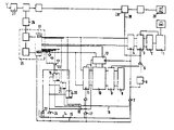
제1도는 본 발명의 제1실시예를 나타낸 블록회로도.1 is a block circuit diagram showing a first embodiment of the present invention.
제2도는 본 발명의 제2실시예를 나타낸 블록회로도.2 is a block circuit diagram showing a second embodiment of the present invention.
* 도면의 주요부분에 대한 부호의 설명* Explanation of symbols for main parts of the drawings
1 : 프로그램유니트 3,11,31 : 메모리1: Program unit 3, 11, 31: Memory
5 : 전송게이트 6 : 타이머5: transmission gate 6: timer
7,17,22,24 : 클록게이트 8 : 비교회로7,17,22,24: clock gate 8: comparison circuit
9 : 어드레스 메모리 10 : 어드레스 디코더9: address memory 10: address decoder
12 : 블록디코더 14 : 블록클록버스12: block decoder 14: block clock bus
15 : 블록넘버버스 16 : 개방버스15: block number bus 16: open bus
18 : AND게이트 19,20,21 : 플립플롭18: AND
23 : 리세트버스 25 : 라디오 데이타 신호디코더23: reset bus 25: radio data signal decoder
28 : 저주파 재생 증폭기 29 : 라우드 스피커28: low frequency reproduction amplifier 29: loudspeaker
본 발명은 사이렌 제어 분야에 관한 것이다.The present invention relates to the field of siren control.
사이렌은 주민들에게 알려줘야 하는 위험의 종류에 따라 서로 다른 시퀀스로 접속 및 차단된다. 사이렌 장치의 현대화 과정에서 사이렌의 무선 원격제어의 과제가 대두되었다.Siren are connected and blocked in different sequences, depending on the type of risk that residents need to be informed of. During the modernization of the siren device, the problem of siren wireless remote control has emerged.
상기 과제는 특허청구범위 제1항에 기재된 장치에 의해 해결된다.The problem is solved by the apparatus described in claim 1.
다른 청구범위에는 본 발명의 개선책이 제시되어 있다.In other claims, improvements of the invention are presented.
첨부한 도면을 참고로 본 발명의 2가지 실시예를 설명하면 다음과 같다.Hereinafter, two embodiments of the present invention will be described with reference to the accompanying drawings.
2가지 실시예에서는 57kHz-부반송파의 진폭 변조로 초단파 방송 신호내에 전송되고 각 방송튜너로 수신 가능한 신호를 통해 사이렌의 무선 원격 제어가 이루어진다.In both embodiments, wireless remote control of the siren is achieved within the microwave broadcast signal with amplitude modulation of the 57 kHz subcarrier and via a signal receivable by each broadcast tuner.
방송 튜너(27)로 원격 제어 송신기가 조절된다. 필요한 경우에 사이렌에 대한 접속 신호를 동반하는 라디오 방송의 재생을 위해 방송 튜너에는 재생 증폭기(28)가 접속되고 이 재생 증폭기에는 라우드 스피커(29)가 접속된다.The
사이렌의 원격 제어를 위해 방송 튜너(27)의 중간 주파수단의 한 출력단이 57kHz-필터(26)와 접속되며, 그 출력단에는 부반송파 진폭으로 부터 제어 신호를 복조하기 위해 라디오 데이타 신호 디코더(25)가 접속되고, 상기 라디오 데이타 신호 디코더는 진폭복조기, 펄스재생기 및 블록 디코더(12)를 포함한다. 상기 진폭 복조기는 블록 디코더(12)에 대한 비트 스트림을 공급한다. 상기의 라디오 데이타 신호 디코더(25)의 구성은 일반적으로 공지되어 있다.One output end of the intermediate frequency stage of the
블록 디코더(12)는 16비트 폭 신호 출력단을 가진다. 또한 블록 디코더(12)의 상응하는 다른 출력단에는 블록 클록버스(14) 및 블록 넙버 버스(15)가 접속된다. 상기 2개의 버스 라인은 4개의 클록 게이트(24),(22),(17),(7)를 제어하고, 이들 클록 게이트중 제1블록 클록에 관련된 클록게이트(24)는 장치내의 모든 메모리 및 플립플롭에 대한 리세트 펄스를 공급하는 반면 제2블록 클록에 관련된 다른 클록게이트(22)는 3플립플롭 (19),(20),(21)에로의 신호 전송을 제어하고 제3 및 제4블록클록에 관련된 나머지 2개의 클록 게이트(17) 및 (7)는 장치의 메모리에로 또는 메모리로 부터의 신호 전송을 제어한다.The
블록 디코더(12)의 16비트 폭 신호 출력단에는 최하위 비트(LSB) 출력단은 제1플립플롭(20)에 대한 활동신호를 공급하고, LSB 출력단에 인접한 블록 디코더의 출력단은 제2플립플롭(21)에 대한 활동신호를 공급하며, 그 입력단이 블록 디코더(12)의 최상위 비트(MSB)출력단 및 4개의 인접한 비트 출력단에 접속된 AND 회로는 제3플립플롭(19)에 대한 활동신호를 공급한다.The least significant bit (LSB) output terminal supplies an activity signal for the first flip-
2개의 플립플롭(19),(20)의 리세트 펄스에 의해 직접 제어 가능한 출력 및 제3플립플롭(21)의 리세트 펄스에 의해 간접 제어 가능한 출력은 AND 게이트(18)에 함께 공급되며, 상기 AND게이트는 해제 버스(16)를 통해 장치의 중간 메모리 내로의 전술한 신호 전송을 준비한다.The output directly controllable by the reset pulses of the two flip-
제1도에 블록 회로도로 도시된 제1실시예에서는 블록디코더(12)의 16개의 신호 출력단이 코딩된 사이렌 어드레스에 대한 16비트 폭 중간 메모리(11)의 신호 입력단과 접속되어 있다. 신호의 전송은 게이트(17)를 통해 개방된다.In the first embodiment shown in the block diagram in FIG. 1, sixteen signal output terminals of the
이것에 대해 병렬로, MSB 출력단을 포함하는 블록 디코더의 신호 출력단 절반은 키워드에 대한 8비트폭 메모리(13)의 신호 입력단과 접속되어 있다. LSB 출력단을 포함하는, 블록 디코더(12)의 신호 출력단의 다른 절반은 개방되어야할 사이렌 프로그램에 대한 8비트 폭 중간 메모리(4)와 접속되어 있다. 상기 중간 메모리(4)에로의 신호 전송은 클록 게이트(7)에 의해 제어된다.In parallel with this, half of the signal output terminal of the block decoder including the MSB output terminal is connected to the signal input terminal of the 8-bit
중간 메모리(11)의 16출력단 및 메모리(13)의 8출력단은 어드레스 디코더(10)의 상응하는 많은 신호 입력단에 접속되어 있고, 상기 어드레스 디코더의 16비트 폭 출력단은 비교회로(8)의 상응하는 16비트 폭 신호 입력단과 접속되어 있다. 비교 회로에 대한 제2정보는, 접속된 사이렌의 미리 정해진 16비트 폭 어드레스가 기억되어 있는 어드레스 메모리(9)에 의해 공급된다.The 16 outputs of the intermediate memory 11 and the 8 outputs of the
어드레스 디코더(10)의 출력단에서의 어드레스가 어드레스 메모리의 어드레스와 일치하면, 비교 회로의 일치 출력단을 통해 전송 게이트(5)는 클록 게이트(7)로부터 지연 회로(6)를 통해 전달된 블록 클록 펄스를 최종 메모리(3) 입력단에 전달할 준비를 한다.If the address at the output of the address decoder 10 coincides with the address of the address memory, the block gate pulse transmitted from the clock gate 7 through the delay circuit 6 to the transfer gate 5 through the coincidence output of the comparison circuit. To be delivered to the final memory 3 input terminal.
접속된 사이렌 프로그램 유니트(1)의 어드레스가 비교 회로에서 수신 신호로 인식되면, 상기 8비트 폭 최종 메모리(3)의 신호 입력단은 중간 메모리(4)로부터 개방되어야할 사이렌 프로그램에 대한 정보를 얻는다. 최종 메모리(3)에서의 명령은 사리렌의 접속 및 차단의 시퀀스를 결정한다. 각 사이렌 프로그램의 끝에서 프로그램 유니트(1)의 리세트 펄스가 최종 메모리(3)의 리세트 입력으로 되돌아가게 된다.When the address of the connected siren program unit 1 is recognized by the comparison circuit as a received signal, the signal input terminal of the 8-bit wide final memory 3 obtains information on the siren program to be opened from the intermediate memory 4. The command in the final memory 3 determines the sequence of connection and disconnection of the sarilens. At the end of each siren program, the reset pulse of the program unit 1 is returned to the reset input of the final memory 3.
기존의 사이렌에 전술한 장치를 접속해야하면, 수신된 8비트 폭 디지탈 신호를 프로그램 유니트(1)의 당해 제어신호로 변환시키는 디지탈 변환기(2)가 최종 메모리(3)와 프로그램 유니트(1) 사이에 설치된다.If the above-described apparatus is to be connected to an existing siren, a digital converter 2 for converting the received 8-bit wide digital signal into the corresponding control signal of the program unit 1 is provided between the final memory 3 and the program unit 1. Is installed on.
라디오 데이타 신호의 전송에 대한 확인에 의해 각 샘플의 제1데이타 블록은 방송국의 식별 부호를 포함한다. 그러나 전술한 장치에서는, 일반적으로 사이렌의 제어가 초단파 범위의 미리 정해진 경고 방송국에 동조되어 있기 때문에 방송국 식별 부호를 인식할 필요가 없다. 따라서 사이렌 제어에 대한 라디오 데이타 신호의 제1블록에 관련된 클록 펄스는 클록게이트(24)를 통해 플립플롭(19),(20),(21) 및 모든 중간 메모리의 리세트를 개방시킨다.The acknowledgment of the transmission of the radio data signal causes the first data block of each sample to contain the broadcast station's identification code. However, in the above-described apparatus, it is generally not necessary to recognize the broadcast station identification code because the control of the siren is tuned to a predetermined warning broadcast station in the microwave range. The clock pulses associated with the first block of radio data signal for siren control thus open the reset of flip-
제2블록에 관련된 클록 펄스에 의해, 블록 디코더(12)가 플립플롭과 접속된 출력단에 신호를 준비하면, 플립플롭(19),(20),(21)은 클록 게이트(22)를 통해 세트된다.When the
제3블록에 관련된 클록펄스에 의해, 선행 클록에서 플립플롭(21)이 세트되지 않았을 경우 블록 디코더 출력단에 접한 상기 제3블록의 신호는 클록 게이트(17)를 통해 중간 메모리(11)로 전송된다.By the clock pulses associated with the third block, when the flip-
제4블록에 관련된 클록펄스에 의해 MSB 출력단을 포함하는 블록 디코더(12) 출력단의 한 절반부의 신호는 키워드로서 클록 게이트(7)를 통해 중간 메모리(13)로 전달되고 블록 디코더의 다른 절반부의 신호는 개방된 사이렌 프로그램으로서 중간 메모리(4)로 전달된다.The signal of one half of the output of the
제4블록 클록 후에 어드레스 디코더(10)의 출력단에 정확한 어드레스가 놓이면, 지연선(6)을 통해 전달된 제4블록 클록에 의해 사이렌 프로그램 명령으로 정해진 중간 메모리(4)의 내용이 최종 메모리(3)로 전달되고 따라서 사이렌 시퀀스가 개방된다.If the correct address is placed at the output terminal of the address decoder 10 after the fourth block clock, the contents of the intermediate memory 4 determined by the siren program command by the fourth block clock transmitted through the delay line 6 become the final memory 3. ) And thus the siren sequence is opened.
다음 그룹의 제1블록에 의해 중간 메모리 및 플립플롭이 다시 리세트된다. 이와는 달리 최종 메모리(3)는, 프로그램 유니트(1)가 개방된 사이렌 스위칭 시퀀의 끝을 표시할때야 리세트 펄스를 얻는다.The intermediate memory and the flip-flop are reset again by the first block of the next group. In contrast, the final memory 3 obtains a reset pulse only when the program unit 1 marks the end of an open siren switching sequence.
정규의 라디오 프로그램 방송으로 사이렌에 대한 스위칭 명령의 방송이 이루어지면 정규의 라디오 방송 프로그램이 재생되지 않아야 한다. 이 경우에는 저주파 재생 증폭기(28) 앞에 음성 회로에 대한 스위치를 설치하며, 이것의 제어 입력단은 전송 게이트(5)의 출력단과 접속된다.If a switching command to the siren is broadcasted by the regular radio program broadcast, the regular radio broadcast program should not be played. In this case, a switch for an audio circuit is provided in front of the low frequency regeneration amplifier 28, and its control input terminal is connected to the output terminal of the transmission gate 5.
제2도에 도시된 제2실시예에서는 블록 디코더(12)의 16신호 출력단이 각 16비트 폭 입력단을 가진 2개의 중간 메모리(11) 및 (31)에 접속되어 있다. 중간 메모리(11)는 제1실시예에서와 마찬가지로 제3블록클록에서 블록 디코더의 출력단에 인가되는 정보를 얻는 반면, 중간 메모리(31)는 제4블록 클록에서 블록 디코더(12)의 출력단에 인가되는 데이타를 기억한다. 이것을 위해 중간 메모리(31)의 입력단은 클록 게이트(7)의 출력단과 접속된다. 메모리(13)의 측면에는 타이머(32)가 접속된다. 예를 들면 라디오 시계와 같은 상기 타이머(32)는 각각 하나의 클록 유니트에 대한 메모리(13)에서 거기에 인가되는 당해 키워드를 호출한다. 상기 키워드에 의해 사이렌 어드레스 및 개방되어야 할 사이렌 프로그램이 중간 메모리(11) 및 (31)에 포함된 32비트 폭 데이타 워드로부터 디코딩된다. 비교기(8)에서 어드레스 워드와 어드레스 메모리(9)에 포함된 사이렌의 어드레스가 비교되는 반면 개방되어야 할 사이렌 프로그램에 대한 명령은 중간 메모리(4)로 전송되며, 상기 중간 메모리의 입력측은 제2실시예에서는 디코더(10)의 6출력단과 접속되어 있다.In the second embodiment shown in FIG. 2, the 16 signal output terminals of the
사이렌 프로그램에 대한 중간 메모리(4)에 인가되는 명령과 비교기(8) 출력신호의 또다른 처리는 제2실시예에서도 제1실시예와 동일하게 이루어진다.Further processing of the command applied to the intermediate memory 4 for the siren program and the output signal of the
Claims (5)
Applications Claiming Priority (3)
| Application Number | Priority Date | Filing Date | Title |
|---|---|---|---|
| DE93823824.1 | 1988-07-14 | ||
| DEP93823824.1 | 1988-07-14 | ||
| DE3823824A DE3823824C1 (en) | 1988-07-14 | 1988-07-14 |
Publications (2)
| Publication Number | Publication Date |
|---|---|
| KR900002223A KR900002223A (en) | 1990-02-28 |
| KR930003449B1 true KR930003449B1 (en) | 1993-04-29 |
Family
ID=6358629
Family Applications (1)
| Application Number | Title | Priority Date | Filing Date |
|---|---|---|---|
| KR1019890009933A KR930003449B1 (en) | 1988-07-14 | 1989-07-12 | Device connected to wireless remotely sirenprograms |
Country Status (8)
| Country | Link |
|---|---|
| US (1) | US4958154A (en) |
| EP (1) | EP0353438B1 (en) |
| JP (1) | JPH0287300A (en) |
| KR (1) | KR930003449B1 (en) |
| AT (1) | ATE83576T1 (en) |
| DE (2) | DE3823824C1 (en) |
| DK (1) | DK169493B1 (en) |
| ES (1) | ES2037913T3 (en) |
Families Citing this family (6)
| Publication number | Priority date | Publication date | Assignee | Title |
|---|---|---|---|---|
| DE3903468A1 (en) * | 1989-02-06 | 1990-08-09 | Blaupunkt Werke Gmbh | INPUT TO PLAY WARNING MESSAGES |
| US5296840A (en) * | 1990-05-25 | 1994-03-22 | Federal Signal Corporation | Programmable emergency signalling system for a vehicle |
| GB9202865D0 (en) * | 1992-02-12 | 1992-03-25 | East Anglian Electronics | Loudspeakers |
| AUPM282493A0 (en) * | 1993-12-06 | 1994-01-06 | Robert Bosch (Australia) Proprietary Ltd. | A siren unit |
| AU2003256156A1 (en) * | 2003-08-04 | 2005-02-15 | Wouter Gort | Method and device for initiating via rds/rbds a desired action related to an external event |
| FR2939230B1 (en) * | 2008-12-02 | 2015-10-30 | Finsecur | MOBILE ALERT DEVICE |
Family Cites Families (6)
| Publication number | Priority date | Publication date | Assignee | Title |
|---|---|---|---|---|
| US4415771A (en) * | 1981-04-03 | 1983-11-15 | Louis Martinez | Public alert and advisory systems |
| US4392248A (en) * | 1981-10-05 | 1983-07-05 | Time And Frequency Technology, Inc. | Attention signal receiver for emergency broadcast systems |
| DE3211813A1 (en) * | 1982-03-31 | 1983-10-13 | Blaupunkt-Werke Gmbh, 3200 Hildesheim | CIRCUIT FOR CONTROLLING THE READINESS OF A MUTED WARNING RADIO RECEIVER |
| US4644327A (en) * | 1982-07-30 | 1987-02-17 | National Research Development Corp. | Methods for generating auditory indicators |
| US4476488A (en) * | 1983-03-23 | 1984-10-09 | Zenith Electronics Corporation | Control circuit for CATV alert system |
| US4688021A (en) * | 1986-03-11 | 1987-08-18 | Bdc Electronics | Combined smoke and gas detection apparatus |
-
1988
- 1988-07-14 DE DE3823824A patent/DE3823824C1/de not_active Expired
-
1989
- 1989-06-20 AT AT89111144T patent/ATE83576T1/en not_active IP Right Cessation
- 1989-06-20 EP EP89111144A patent/EP0353438B1/en not_active Expired - Lifetime
- 1989-06-20 ES ES198989111144T patent/ES2037913T3/en not_active Expired - Lifetime
- 1989-06-20 DE DE8989111144T patent/DE58903005D1/en not_active Expired - Fee Related
- 1989-07-11 DK DK343189A patent/DK169493B1/en not_active IP Right Cessation
- 1989-07-11 JP JP1177293A patent/JPH0287300A/en active Pending
- 1989-07-12 KR KR1019890009933A patent/KR930003449B1/en not_active IP Right Cessation
- 1989-07-12 US US07/378,634 patent/US4958154A/en not_active Expired - Lifetime
Also Published As
| Publication number | Publication date |
|---|---|
| KR900002223A (en) | 1990-02-28 |
| DK343189A (en) | 1990-01-15 |
| US4958154A (en) | 1990-09-18 |
| DE58903005D1 (en) | 1993-01-28 |
| EP0353438A1 (en) | 1990-02-07 |
| DK169493B1 (en) | 1994-11-07 |
| ATE83576T1 (en) | 1993-01-15 |
| DE3823824C1 (en) | 1989-10-19 |
| EP0353438B1 (en) | 1992-12-16 |
| DK343189D0 (en) | 1989-07-11 |
| JPH0287300A (en) | 1990-03-28 |
| ES2037913T3 (en) | 1993-07-01 |
Similar Documents
| Publication | Publication Date | Title |
|---|---|---|
| AU596995B2 (en) | Device located at the receiver end for actuation controlled from the transmitter end | |
| CA1162613A (en) | Digital radio paging communication system for distinguishing between calling signal or display information signal | |
| US5101510A (en) | Energy conserving stand-by function in radio traffic report receiver | |
| JPS6467037A (en) | Receiving method in rds system radio | |
| KR930003449B1 (en) | Device connected to wireless remotely sirenprograms | |
| CN102421175B (en) | Device and method for reduced power consumption | |
| EP0364749A3 (en) | Radio receiver | |
| KR19980074989A (en) | Ioen information storage processing method of car audio for RDS broadcasting reception | |
| EP0464328B1 (en) | Multivoice broadcast search method and apparatus in NICAM broadcasting receiver | |
| JPS6490609A (en) | Rds automatic tracking system | |
| US4868891A (en) | Interrupted audio fill-in system for noise reduction and intelligibility enhancement in multi-channel scanning receiver applications | |
| KR0120924B1 (en) | Warning messages reproduction system | |
| DE59712853D1 (en) | Method for receiving and evaluating RDS data streams from multiple transmitters | |
| JP2885809B2 (en) | Receiving machine | |
| GR3003740T3 (en) | ||
| DE2966360D1 (en) | Dictate station identifier | |
| DK163627C (en) | DIGITAL SIGNAL TRANSMISSION SYSTEM, NAME FOR SATELLITE RADIO | |
| CA1071713A (en) | Circuit arrangement for the identification of a series of unknown code words | |
| EP0326746A3 (en) | Radio data system receiver | |
| KR100188263B1 (en) | Method of the catv reservation record | |
| JPH03110927A (en) | Fmx receiver | |
| JPH05153673A (en) | Device to be controlled by remote control | |
| JPH0653782A (en) | Car radio | |
| JPS5680945A (en) | Two-way signal transmitter | |
| JPS6259450A (en) | Signal input circuit |
Legal Events
| Date | Code | Title | Description |
|---|---|---|---|
| A201 | Request for examination | ||
| G160 | Decision to publish patent application | ||
| E701 | Decision to grant or registration of patent right | ||
| GRNT | Written decision to grant | ||
| FPAY | Annual fee payment |
Payment date: 20030326 Year of fee payment: 11 |
|
| LAPS | Lapse due to unpaid annual fee |