KR920009016B1 - Apparatus for measuring the position of a moving member relative to a fixed member - Google Patents
Apparatus for measuring the position of a moving member relative to a fixed member Download PDFInfo
- Publication number
- KR920009016B1 KR920009016B1 KR1019830006136A KR830006136A KR920009016B1 KR 920009016 B1 KR920009016 B1 KR 920009016B1 KR 1019830006136 A KR1019830006136 A KR 1019830006136A KR 830006136 A KR830006136 A KR 830006136A KR 920009016 B1 KR920009016 B1 KR 920009016B1
- Authority
- KR
- South Korea
- Prior art keywords
- windings
- transformers
- row
- transducers
- rows
- Prior art date
Links
Images


Classifications
-
- G—PHYSICS
- G21—NUCLEAR PHYSICS; NUCLEAR ENGINEERING
- G21C—NUCLEAR REACTORS
- G21C17/00—Monitoring; Testing ; Maintaining
- G21C17/10—Structural combination of fuel element, control rod, reactor core, or moderator structure with sensitive instruments, e.g. for measuring radioactivity, strain
- G21C17/12—Sensitive element forming part of control element
-
- G—PHYSICS
- G01—MEASURING; TESTING
- G01B—MEASURING LENGTH, THICKNESS OR SIMILAR LINEAR DIMENSIONS; MEASURING ANGLES; MEASURING AREAS; MEASURING IRREGULARITIES OF SURFACES OR CONTOURS
- G01B7/00—Measuring arrangements characterised by the use of electric or magnetic techniques
- G01B7/14—Measuring arrangements characterised by the use of electric or magnetic techniques for measuring distance or clearance between spaced objects or spaced apertures
-
- G—PHYSICS
- G01—MEASURING; TESTING
- G01D—MEASURING NOT SPECIALLY ADAPTED FOR A SPECIFIC VARIABLE; ARRANGEMENTS FOR MEASURING TWO OR MORE VARIABLES NOT COVERED IN A SINGLE OTHER SUBCLASS; TARIFF METERING APPARATUS; MEASURING OR TESTING NOT OTHERWISE PROVIDED FOR
- G01D5/00—Mechanical means for transferring the output of a sensing member; Means for converting the output of a sensing member to another variable where the form or nature of the sensing member does not constrain the means for converting; Transducers not specially adapted for a specific variable
- G01D5/12—Mechanical means for transferring the output of a sensing member; Means for converting the output of a sensing member to another variable where the form or nature of the sensing member does not constrain the means for converting; Transducers not specially adapted for a specific variable using electric or magnetic means
- G01D5/14—Mechanical means for transferring the output of a sensing member; Means for converting the output of a sensing member to another variable where the form or nature of the sensing member does not constrain the means for converting; Transducers not specially adapted for a specific variable using electric or magnetic means influencing the magnitude of a current or voltage
- G01D5/20—Mechanical means for transferring the output of a sensing member; Means for converting the output of a sensing member to another variable where the form or nature of the sensing member does not constrain the means for converting; Transducers not specially adapted for a specific variable using electric or magnetic means influencing the magnitude of a current or voltage by varying inductance, e.g. by a movable armature
- G01D5/204—Mechanical means for transferring the output of a sensing member; Means for converting the output of a sensing member to another variable where the form or nature of the sensing member does not constrain the means for converting; Transducers not specially adapted for a specific variable using electric or magnetic means influencing the magnitude of a current or voltage by varying inductance, e.g. by a movable armature by influencing the mutual induction between two or more coils
- G01D5/2046—Mechanical means for transferring the output of a sensing member; Means for converting the output of a sensing member to another variable where the form or nature of the sensing member does not constrain the means for converting; Transducers not specially adapted for a specific variable using electric or magnetic means influencing the magnitude of a current or voltage by varying inductance, e.g. by a movable armature by influencing the mutual induction between two or more coils by a movable ferromagnetic element, e.g. a core
-
- Y—GENERAL TAGGING OF NEW TECHNOLOGICAL DEVELOPMENTS; GENERAL TAGGING OF CROSS-SECTIONAL TECHNOLOGIES SPANNING OVER SEVERAL SECTIONS OF THE IPC; TECHNICAL SUBJECTS COVERED BY FORMER USPC CROSS-REFERENCE ART COLLECTIONS [XRACs] AND DIGESTS
- Y02—TECHNOLOGIES OR APPLICATIONS FOR MITIGATION OR ADAPTATION AGAINST CLIMATE CHANGE
- Y02E—REDUCTION OF GREENHOUSE GAS [GHG] EMISSIONS, RELATED TO ENERGY GENERATION, TRANSMISSION OR DISTRIBUTION
- Y02E30/00—Energy generation of nuclear origin
- Y02E30/30—Nuclear fission reactors
Abstract
내용 없음.No content.
Description
제1a도는 균일한 자장(Hc)내에 위치한 자력계형 변환기를 나타낸도.Figure 1a shows a magnetometer transducer located in a uniform magnetic field Hc.
제1b도는 자장(Hc)의 함수로써 변환기에 의해서 생성된 피이크 전류(Is)의 변화를 도시하는 그래프.FIG. 1B is a graph showing the change in the peak current Is generated by the transducer as a function of the magnetic field Hc.
제2a도는 본 발명의 제1구조적 변형에 따라서 몇몇 자력계형 변환기를 갖는 바아의 위치를 측정하기 위한 장치의 설치를 도시하는 흡수봉과 그 안내 재킷용 제어 바아의 종단면도.FIG. 2A is a longitudinal sectional view of an absorbing rod and a control bar for a guide jacket showing the installation of a device for measuring the position of a bar having several magnetometer transducers in accordance with a first structural variant of the invention.
제2b도는 제2a도의 선 IIB-IIB를 따라 취한 단면도.FIG. 2B is a cross sectional view taken along the line IIB-IIB of FIG. 2A;
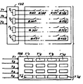
제3도는 제2도 장치의 자력계형 변환기용 전기 연결회로와 변환기용 여기 및 판독회로도.3 is an electrical connection circuit for magnetometer transducers of the FIG. 2 apparatus and an excitation and reading circuit for the transducer.
제4도는 변화기용 여기회로의 상세도.4 is a detailed view of the excitation circuit for the transformer.
제5도는 변환기용 판독회로의 상세도.5 is a detailed view of a readout circuit for a converter.
제6도는 완성된 측정장치용 제어회로의 일반적인 블록도.6 is a general block diagram of a control circuit for a completed measuring device.
제7도는 검출기로써 가요성 리이드 스위치를 사용한 본 발명의 제2구조적 변형에의 사시도.7 is a perspective view of a second structural variant of the present invention using a flexible lead switch as detector.
제8도는 제7도 스위치의 전기 연결회로를 도시하는, 제3도에 비교되는 도.FIG. 8 is compared to FIG. 3, showing the electrical connection circuit of the FIG. 7 switch.
제9도는 판독회로의 변압기중 하나를 리이드 스위치에 연결하는 상세도.9 is a detailed view of connecting one of the transformers of the readout circuit to the lead switch.
제10도는 제7도에서 9도까지의 변형예에서 변환기의 판독회로의 상세도.FIG. 10 is a detailed view of the reading circuit of the transducer in variants 7 to 9;
본 발명은 바아가 이동하는 원통형 밀봉체와 같은 고정부재에 관해 바아와 같은 이동부재의 위치를 측정할수 있는 장치에 관한 것이다.The present invention relates to a device capable of measuring the position of a moving member, such as a bar, with respect to a stationary member, such as a cylindrical seal, on which the bar moves.
이러한 종류의 장치는, 특히 흡수 제어봉의 위치를 측정하는데 사용되며, 제어봉은 어떤 형태의 원자로(가압수형, 비등수형 또는 고속중성자형)의 노심에서 반응도를 검사할수 있게 해준다. 그러나 본 발명은 이러한 응용에 제한되는 것이 아니며, 악조건 하에서도 장치의 전체 크기를 크게함 없이 주어진 방향으로 가동한는 부재의 위치를 정확하게 알 필요가 있는 모든 경우에 사용될수 있다.Devices of this kind are used, in particular, to measure the position of absorption control rods, which allow the reactivity to be examined in the core of any type of reactor (pressurized, boiling or fast neutron). However, the present invention is not limited to this application, and can be used in all cases where it is necessary to accurately know the position of the member that moves in a given direction without increasing the overall size of the apparatus even under adverse conditions.
현재의 기술 수준에서는, 900MW 가압수형 원자로의 노심에서 제어봉의 변위 검출은 차동 변압기에 의해 수행되고 있다. 그러나 이러한 형태의 검출기의 분해능은 정확하지 못하다(제어봉의 전행정의 1/30, 즉 3700mm의 행정에 대해 123mm). 더욱이 기구당 1개 이상의 검출기를 설치할 수는 없다.At the current state of the art, displacement detection of control rods at the core of a 900 MW pressurized water reactor is performed by a differential transformer. However, the resolution of this type of detector is not accurate (1/30 of the full stroke of the control rod, 123 mm for a stroke of 3700 mm). Moreover, it is not possible to install more than one detector per instrument.
이와같은 한계는, 이 종류의 원자로에 있어서는 기본적으로 중요한 문제로는 되지않만, 작동 조건의 최적화로 노심에서 흡수봉의 위치를 매우 정확하게 검사하며, 이 측정에 기인하여 각 검사기구의 리던던트 측정을 수반하는 안전 조건이 필요한 소정의 원자로 프로젝트의 경우에는 아주 분리한 문제로 될 수 있다.This limitation is not a fundamentally important issue for this type of reactor, but due to the optimization of the operating conditions, the location of the absorber rods at the core is very precisely inspected, and this measurement entails redundant measurement of each inspection instrument. In some reactor projects where safety conditions are required, this can be a very separate problem.
따라서, 본 발명은 종래장치의 형태를 갖지 않고 리던던트 측정을 가능하게 하고, 위치의 절대측정을 할수 있으며, 필요할 때 정확한 위치측정을 할수 있는 장치에 관한 것이다.Accordingly, the present invention relates to a device capable of making a redundant measurement without the form of a conventional device, an absolute measurement of a position, and an accurate position measurement when necessary.
본 발명은 특히 고정부재에 관한 주어진 방향으로 가동부재의 위치를 측정하기 위한 장치에 관한 것이며, 상기 장치는 가동부제에 의해서 반송된 자속발생 마아크와, 자속의 영향에서 상태를 변환기가 자속의 영향하에 상태를 변화하도록, 주어진 방향으로 고정부재상에 규칙적인 간격으로 위치해 있으며, 동일행의 변환기는 n개의 행과 p개의 열로된 매트릭스에 따라서 전기적으로 그룹으로 형성되어 있고, n개의 행은 공급 수단에 차례로 공급되며, p개의 열은 판독장치에 의해 차례로 처리됨을 특징으로 하고 있다.The present invention relates in particular to a device for measuring the position of a movable member in a given direction with respect to a stationary member, said apparatus comprising a flux generating mark conveyed by a movable subdivision and a state in which the transducer is influenced by the magnetic flux. Located at regular intervals on the stationary member in a given direction so as to change state, the transducers of the same row are electrically grouped according to a matrix of n rows and p columns, n rows being supplied to the supply means. The p rows are supplied one by one, and are sequentially processed by the reader.
본 발명의 실시예에 따라서, 공급 수단은, 교류 전원에 접속될수 있는 1차 권선과 동일행의 변환기와 직렬로 접속된 2차 권선을 각각 갖는 n개의 변압기를 포함하고 있다.According to an embodiment of the invention, the supply means comprises n transformers each having a primary winding which can be connected to an alternating current power supply and a secondary winding which is connected in series with a converter in the same row.
또한 n개의 변압기 각각은 제어권선을 포함하고, n개의 변압기는 a행 b열의 매트릭스에 따라서 전기적으로 그룹을 형성되어 있으며, 1차 권선과 제어 권선은 1행식, 1열씩 직렬로 각각 접속되고 교류 전원과 포화 직류 전원에 각각 접속될수 있다.In addition, each of the n transformers includes control windings. The n transformers are electrically grouped according to a matrix of rows a and b. The primary windings and the control windings are connected in series, one row and one column, respectively. And can be connected to saturated DC power respectively.
이 경우에, 또한 공급수단은 공급 라인을 포함할수 있으며, 이들 공급라인의 각각은 콘덴서를 통해서 1차권선(Ep)의 행과 다이오드를 통해서 제어권선(Ec)의 행에 연결되어 있다.In this case, the supply means may also comprise a supply line, each of which is connected to the row of the primary winding Ep through a capacitor and to the row of the control winding Ec through a diode.
본 발명의 본 실시예에 있어서, 판독수단은![]()
![]()
![]()
![]()
![]()
![]()
이 경우 판독수단은, 또한 K개의 측정 행을 포함하고 있으며, 측정행의 각각은 콘덴서를 통해서 2차 권선의 행과 다이오드를 통해서 제어권선의 열에 접속되어 있다.In this case, the reading means further includes K measurement rows, each of which is connected to a row of control windings through a row of secondary windings and a diode through a capacitor.
본 발명의 제1구조적 변형예에 따라서, 자기변환기는 직사각형의 히스테리시스 루우프를 구비한 자심과, 각각 여기 및 판독소자로 구성되어 자심에 감겨진 2개의 권선을 갖는 자력형 변환기이며, 동일행의 변환기의 여기 소자는 직렬로 접속되었으며, 동일 열의 변환기의 판독소자는 병렬로 접속되어 있다.According to a first structural variant of the invention, the magnetic transducer is a magnetic transducer having a magnetic core with a rectangular hysteresis loop and two windings wound around the magnetic core, each consisting of excitation and reading elements, and a transducer in the same row The excitation elements of are connected in series, and the reading elements of the converters of the same column are connected in parallel.
이 경우 자기계형 변환기는 비자성 지지체에 바람직하게 고정되고 자기분로에 의해 분리되며, 변환기, 지지체 및 분로는, 가동부재에 관해 고정부재의 반대측에 배치된 비자성 튜브내에 수용되어 있다.The magnetic field transducer is in this case preferably secured to the nonmagnetic support and separated by a magnetic shunt, the transducer, the support and the shunt being housed in a nonmagnetic tube disposed on the opposite side of the stationary member with respect to the movable member.
본 발명의 제2구조적 변형에 따라서, 변환기는 리이드 스위치이며, 동일행의 스스위치는 직렬로 접속되며, 각각![]()
![]()
![]()
![]()
이 경우 리이드 스위치는 자성 물질로 제조된 전도체에 의해 전기적으로 연결되어 있으며, 절연 커넥터 지지체에 고정되어 있으며, 스위치, 도체, 지지체 및 커넥터는 가동부재에 관한 고정부재의 다른 측면에 위치한 비자성 튜브에 위치하고 있다.In this case, the lead switch is electrically connected by a conductor made of magnetic material, and is fixed to the insulated connector support, and the switch, the conductor, the support and the connector are connected to a nonmagnetic tube located on the other side of the fixing member with respect to the movable member. Is located.
본 발명은 또 다른 관점에서, 변환기의 다수행이 가동부재 주위의 고정 부재상에 배치되었으며, 각 행의 변환기는 바아 위치의 리던던트 측정을 제공하기 위해 동일 레벨에 위치한다.In another aspect of the invention, a plurality of rows of transducers are disposed on a stationary member around the movable member, with each row of transducers positioned at the same level to provide a redundant measurement of bar position.
본 발명의 또 다른 관점에 따라서, 가동부재는 주어진 증가 단계에서 따라서 이동되며, 동일행의 두 인접한 자력계형 변환기 사이의 거리는 상기 단계의 2배와 동일하다.According to another aspect of the invention, the movable member is moved according to a given incremental step, and the distance between two adjacent magnetometer transducers in the same row is equal to twice that of the step.
본 발명은 첨부 도면을 참고로 비제한적인 두 실시예에 관한 좀더 상세히 서술하고저 한다.The invention is described in more detail with respect to two non-limiting embodiments with reference to the accompanying drawings.
자력계형 변환기를 사용하는 것이 바람직한 상술한 제1구조적 변형예의 이해를 쉽게 하기 위해 먼저 제1a도와 1b도를 참고로 이러한 변환기의 작동원리를 참고 할수 있을 것이다. 좀더 상세히 말하면 자계 검출기에 관해 코미싸리아따레너지 아토미크의 이름으로 1978년 5월 8일 출원된 프랑스 공화국 특허출원 7,813,438호를 참고할수 있을 것이다. 홀 프로우브(Hall probe)와 같은 다른 변환기의 형태가 본 발명의 영역을 벗어나지 않는 범위에서 자력계를 대신하여 사용할수 있다.In order to facilitate understanding of the first structural variant described above, which is preferable to use a magnetometer transducer, reference may be made to the principle of operation of such a transducer with reference to FIGS. 1A and 1B. More specifically, reference may be made to the French Republic Patent Application No. 7,813,438, filed May 8, 1978, on the field detector, in the name of Comasaria Tarnage Atomik. Other transducer types, such as Hall probes, may be used in place of magnetometers without departing from the scope of the present invention.
제1a도는 자력계형 변환기(10)가 토로이달(toroidal) 자기회로(12)의 형태를 가지고 있으며, 자성재 테이프로 실현되며, 직사각형 히스테리시스 루우프를 구비하고 있다는 것을 도시하고 있다. 본 출원에서 자기회로(12)는 전류 변압기의 자심으로 구성되었으며, 이러한 목적을 위해 1차 여기권선(14)과 2차 판독권선(16)이 상기 자심에 감겨 있다. 이제 자심의 축에 수직인 균일 자장(Hc)내에 위치한 자심을 고려해 보자. 이 자장은 자장과 동일한 방향으로 자심내의 자속 순환을 일으키고, 제1도에서 a와 b로 표시된 부채꼴 형태의 자심에서 최대유도를 일으킨다.FIG. 1A shows that the
교류전류(Ip)가 1차 권선(14)에 흐르게 되면, 부채꼴 a또는 b중 하나에서 자장(Hc)에 의해 발생된 것에 계속 첨가되며 다른 것에서는 감소되는 자속을 순환하게 한다. 권선(14)에 의해 발생된 자계(HA)의 반쪽 사이클이나 변화가 무엇이나든 간에 두자계(HA와 HC)가 서로에 첨가되는 최소한 하나의 부채꼴이 항상 존재하게 된다. 이 부채꼴에서 유용한 유도 변화는 다음과 같다.As the alternating current Ip flows in the primary winding 14, it continues to add to that generated by the magnetic field Hc in one of the sectors a or b and circulates the reduced magnetic flux in the other. Whatever the half cycle or change in the magnetic field H A generated by the winding 14, there will always be at least one sector with two magnetic fields H A and H C added to each other. Useful induction changes in this sector include:
△B=BS-(μ0·μr·HC) △ B = B S - (μ 0 · μ r · H C)
여기서 BS는 자성체의 포화시 유도 μ0는 공기(4π10-7)의 도자율, μr는 자성체의 도자율, HC는 외부 균일자장.Where B S is the induction at saturation of the magnetic material μ 0 is the magnetic flux of air (4π10 -7 ), μ r is the magnetic flux of the magnetic body, and H C is the external uniform magnetic field.
자성체가 포화되어![]()
![]()
이제 완전한 자심을 고려해 보면, 모든일이 포화된 부채꼴에 상응하는 공기갭에 의해 방해를 받고 공기에 서 누출자속을 무시하면 유도변화는 부채꼴(sector)에 존재하는 곳과 동일하게 압도한다.Considering the complete self now, if everything is interrupted by an air gap corresponding to a saturated fan and the leakage flux in the air is ignored, the induced change is overwhelmed by where it is in the sector.
제1b도의 곡선은 외부자장(HC)의 함수로써 2차 피이크 전류(IS)의 진폭을 나타내며, 1차 전류는 100㎃에서 일정한 피이크 10KHZ로 유지된다. 따라서 이 곡선의 결과로써, 자력계형 변환기(10)가 2차 전류(IS)를 측정 하므로써 균일자장(HC)의 존재를 검출하기 위한 변환기로 사용하는 것에 유리하다는 것을 명백히 알게 된다.The curve in FIG. 1b represents the amplitude of the secondary peak current I S as a function of the external magnetic field H C , and the primary current is maintained at a constant peak 10KH Z at 100 Hz. Thus, as a result of this curve, it becomes clear that the
자력계형 변환기는 특히 원자로에서 제어봉을 지니는 바아의 변위를 검출하는데 응용하면 상당한 장점을 가지게 된다.Magnetometer transducers have significant advantages, especially when applied to detect displacement of a bar with control rods in a reactor.
전체크기의 감소(예, 약2mm의 높이에 대해 외부직경은 5.3mm)권선을 적절히 절연하면, 350℃에 이르면 양호한 열이동. 도함수에 대해서가 아닌, 자계의 절대치에 대한 감도. 자심의 축에 평행하게 만들어진 자장에 대한 거의 완전한 불감성(어떤 응용에 대해서는 중요한 방향효과).Reduced overall size (e.g. external diameter is 5.3mm for a height of about 2mm) With adequate insulation, good heat transfer at 350 ° C. Sensitivity to the absolute value of the magnetic field, not to derivatives. Nearly complete insensitivity to the magnetic field made parallel to the axis of the magnetic core (an important directional effect for some applications).
제2a도와 2b도는 비자성 밀봉체(20)내에서 바아(18)의 위치를 측정하는데 이러한 자력계형 변환기를 사용하는 것을 도시하고 있다.2A and 2B illustrate the use of such magnetometer transducers to measure the position of the
본 발명의 기본 원리는 환상 영구자석(22)으로 구성되어, 자기 인덱스 또는 마아크를 가지고 있는 봉(18)을 제공하는데 있으며, 영구자석의 위치는 원통형 밀봉체의 모체에 위치한 자력계형 변환기(10)에 의해 검출된다. 좀더 자세히 말하면 환상 영구자석(22)은 바아(18)에 고정되도록 삽입된 지지체(24)상에 설치되어 있다. 제어 바아가 자속을 발생할 경우(제어 코일과 강자성 스틸바아를 사용함) 영구자석은 절대적으로 필요한 것은 아니다.The basic principle of the present invention consists of an annular
종래의 결점을 갖지 않고 절대치의 측정을 수행하기 위하여 자력계(10)는 바아(18)의 유용행로의 모든점에 영구자석(22)에 의해서 여기되는 최소한 하나의 자력계가 항상 존재하여 두 개의 인접 변환기가 자석에 의해 동시에 여기될수 있도록 설치된다. 자석의 크기는 적당히 선택되어야 한다. (두 개의 연속적인 변환기를 분리하는 갭에 근접한 길이) 더욱이 두 개의 인접한 변환기 사이에서 자속의 연속성을 유지하기 위해 변환기를 분리하는 갭이 중간 스틸부(26)에 의해 자기적인 분로를 형성한다.In order to carry out an absolute measurement without conventional drawbacks, the
이러한 응용이 원자로에서 흡수봉을 지니는 바아의 변위를 측정하기 위해 사용될 때, 상기 바아(18)는 주어진 증가 단계에 따라서 이동한다. 투자기계 사이의 갭은 흡수봉의 제어 바아의 변위를 특정화하는 증가단계에 동일한 측정값을 얻을수 있도록 규정된다. 두 개의 연속적인 자력계형 변환기를 동시에 여기시킬 가능성은 두간계로 연속적으로 간격진 이들 두 변환기 사이의 중간위치를 검출하기 위해 사용된다. 바아의 변위를 특정화하는 증가단계는 예를 들어 16mm이며, 흡수봉의 전행로는 예를들어 259단계로 되어 있다. 따라서 두 개의 연속적인 자기계 사이의 거리는 32mm이며, 원통형 밀본체(20)의 모체에 따라서 배열된 변환기의 각행은 128개의 자력계형 변환기로 구성되어 있다.When this application is used to measure the displacement of a bar with absorbing rods in a reactor, the
원자로에 사용할때는 특별히 엄중한 안전 규칙을 포함(32)에 의해 감겨있으며, 그의 모든 단부는 안내관의 상단부에 위치한 상호 연결박스(34)로 들어간다. 자력계형 변환기의 2차 권선(16)에 관한 연결은 검출기 내의 변환기 위치가 어디이든 간에 하중 임피던스(R) (제1도 참조)가 동일하도록 조직 된다. 제3도를 참고하면 쉽게 알수 있겠지만 P개의 변환기의 그룹에 의한 것을 제외하고는 동일한 과정이 1차 권선(14)에 적용된다. 이러한 목적을 위해 1차 권선의 하단부는 P개 변환기(10)의 동일 그룹중 1차 권선(14)이 직렬로 연결되도록 가장 빠른 루우트로 상호 연결박스(34)를 통과하며, 반면 1차 권선의 다른 단부는 안내관(30)에서 박스(34)까지 상승하기 전에 원통형 밀봉체(20)의 저단부를 통해 통과한다.When used in a nuclear reactor, it is wound by a special string of safety rules (32), all of which end into an interconnect box (34) located at the top of the guide tube. The connection with respect to the secondary winding 16 of the magnetometer transducer is organized such that the load impedance R (see FIG. 1) is the same whatever the transducer position in the detector. Referring to FIG. 3, it will be readily understood, but the same process applies to the primary winding 14, except by a group of P transducers. For this purpose, the lower end of the primary winding passes through the
박스(34)내에서 와이서(32)의 상호연결 회로는 제3도에 도시되어 있다. 좀더 이해를 쉽게 하기 위해 제3도는 변환기(10)의 레벨에 있는 와이어(32) 사이의 상이한 연결을 도시하고 있는 반면 이들 연결은 실제 안내관의 상단부에서 상호 연결박스(34)내에 위치한다.The interconnect circuitry of the
제3도에 도시된 것과 같은 상호연결회로는 각행의 변환기에 연결되었다는 것이 명백한다. 제3도는 각행의 변환기가 1에서 64까지의 변환기 64개로 구성되었다는 것을 보여준다. 그러나 특별한 행의 변환기수는 본 발명의 범위를 벗어나지 않고 이와 다를 수도 있다.It is evident that an interconnect circuit such as that shown in FIG. 3 is connected to each row of transducers. 3 shows that each row of transducers consists of 64 transducers from 1 to 64. However, the number of converters in a particular row may be different without departing from the scope of the present invention.
본 발명에 따라서, 제3도는 도시된 것과 같이 전기적인 관점에서 n개의 행과 p개의 열을 갖는 변환기의 직사각 매트릭스를 규정하기 위해 상호연결 회로는 동일행의 변환기를 연결한다. 즉 첫 번째 행의 p개의 변환기는 매트릭스의 제1해을 구성하며, 다음의 p개의 변환기는 제2행을 구성하고, 그 다음도 동일하다. 행의 수(n)는 열의 수(p)보다 적은 것이 바람직하며, 수n 및 p는 n.p의 곱이 동일행의 변환기의 수와 동일하도록 선택되어야 한다.In accordance with the present invention, FIG. 3 illustrates an interconnect circuit connecting the same rows of transducers to define a rectangular matrix of transducers having n rows and p columns from an electrical perspective as shown. That is, the p transformers in the first row constitute the first solution of the matrix, the next p transformers constitute the second row, and so on. The number n of rows is preferably less than the number p of columns, and the numbers n and p should be chosen such that the product of n.p is equal to the number of converters in the same row.
제3도에 도시한 실시예에서, 각행은 64개의 변환기로 구성되고, 변환기의 매트릭스는 4행과 16열로 구성된다는 것을 알수 있다. 제3도에 도시된 것처럼, 변환기의 상호 연결회로는 변환기 매트릭스의 동일행의 1차 여기권선(14)은 직렬로 연결되고 동일 매트릭스 열의 2차 판독권선(16)은 병렬로 연결되도록 해야한다.In the embodiment shown in FIG. 3, it can be seen that each row consists of 64 transducers and the matrix of transducers consists of 4 rows and 16 columns. As shown in FIG. 3, the interconnection circuit of the converter must ensure that the primary excitation windings 14 of the same row of the converter matrix are connected in series and the
매트릭스의 형태로 변환기를 상호 연결하므로써, 여기전류(Ip) (제1도)는 1행의 모든 여기권선으로 동시에 들어가며, 변환기의 상태는 열마다 2차 전류(Is)를 측정하므로써 분석된다. 이러한 작동은 자석 지표 또는 표시(22)의 존재로 여기되는 변환기를 위치하기 위해 모든 행을 연속적으로 여기하므로써 되풀이 된다.By interconnecting the transducers in the form of a matrix, the excitation current Ip (FIG. 1) enters all the excitation windings in a single row simultaneously, and the state of the transducer is analyzed by measuring the secondary current Is per column. This operation is repeated by successively exciting all rows to locate a transducer that is excited with the presence of a magnetic indicator or
이러한 표시는 변환기가 자기 표시의 존재로 포화되었을 때 2차 전류(Is)가 최소에 있고, 포화되지 않았을 때 최대에 있다는 것을 이용한다. n개의 2차 권선(16)의 열이 병렬로 배열된 것은 다른 n-1행의 여기되지 않은 변환기가 유용한 신호로부터 자기 전력를 소비하기 때문에 어떤 주의가 필요하다. 이러한 효과를 최소화 하기 위해 하중 임피던스(R)(제1도)가 2차 전압을 감소하려고 최소로 감소하며, 따라서 자기화 전류는 병렬로 위치한 변환기(10)에 공급된다. 이와같이 것이 직사각형 매트릭스가 정방형 매트릭스에 비해 선택되는이유중의 하나다.This indication utilizes that the secondary current Is is at its minimum when the transducer is saturated with the presence of the magnetic indication and at its maximum when it is not saturated. The arrangement of the columns of n
최대치를 감소하기 위해 상호 연결상자(34)를 전자 처리회로에 연결하는 권선의 체적은 서술한 응용에서 원자로 빌딩이 외부에 설치되며, 박스(34)내에 다중회로를 제공하는 것도 제안되었다. 제3도는 매트릭스에서 n개의 행의 각변환기(10)의 1차 권선(14)을 연속적으로 여기할수 있는 공급회로(36)와 매트리스에서 p개의 열의 각 변환기의 2차 권선을 연속적으로 주사할수 있는 판독회로(38)를 도시한다.In order to reduce the maximum, the volume of the windings connecting
제4도는 공급회로(36)의 양호한 실시예를 도시한다. 상기 회로는 본 발명의 범주를 벗어나지 않는 범위에서 다른 공지된 다중회로로 대처될수 있다는 것이 명백하다.4 shows a preferred embodiment of the
회로(36)는 n개의 변환기(T)를 포함한다. (본 실시예에서는 T1에서 T4로 표시된 4개). 또는 변압기는 변환기 매트릭스의 n개의 행(y1에서 y4)의 각각에 연결되어 있다. 각각의 변환기(T)는 도시하지 않은 자심에 감겨진 세 개의 동일한 권선(EC, EP및 ES)을 포함하고 있다. 이들 권선은 각각 제어권선(EC), 1차 권선(EP) 및 2차 권선(ES)으로 구성되어 있다. 각 변압기의 2차 권선(ES)은 그에 상응하는 변환기행의 여기권선(14)과 직렬로 접속되어 있다.The
변압기의 1차 권선(EP)은 예를들어 매트릭스의 행의 순서에 따라서 한쌍씩 직렬로 연결되어 있다(한쪽에 T1및 T2, 다른쪽에 T3및 T4의 1차 권선이 직렬로 연결됨). 마지막으로 제어권선(EC)은 1차 권선(EP)의 것과는 상이한 그룹을 따라서 한쌍식 직렬로 연결되어 있다. 예를 들어 제4도의 경우에 한쪽에 T1및 T4, 다른쪽에 T2및 T3의 제어권선이 직렬로 연결되어 있다. 공급회로(36)는 또한 처리회로에서 여기 전류를 순환하는![]()
![]()
라안(Y1및 Y2)은 라인(Y1및 Y2)에서 Y0를 통과하여 각각 두 다이오드(D1및 D3)를 통해서 변압기(T1및 T4)의 제어수단(EC)를 공급한다. 또한 라인(Y1및 Y2)은 라인(Y0)에서 Y1및 Y2로 통과하여 각각 두 다이오드(D2및 D'4)를 가로질러 변압기(T2및 T3) 제어권선을 공급한다.Raan Y 1 and Y 2 pass through Y 0 in lines Y 1 and Y 2 and control means E C of transformers T 1 and T 4 through two diodes D 1 and D 3 , respectively. To supply. Further line (Y 1 and Y 2) are lines (Y 0) from the Y 1 and Y two diodes through to 2 (D 2 and D '4) transformer across the (T 2 and T 3) a control winding supplied do.
마지막으로 저항기(R1및 R2)가 한쪽의 변압기(T1및 T4) 그리고 다른 쪽의 변압기(T2및 T3)의 제어권선(EC)에 각각 직렬로 위치한다.Finally, resistors R 1 and R 2 are located in series with the control windings E C of one transformer T 1 and T 4 and the other transformers T 2 and T 3 , respectively.
제4도를 참고로 서술된 공급회로(36)의 결과로써, 필요시 연속적으로 n개의 라인(Y2-Y2)에 대해 처리회로에 공급된 여기 전류를 전환할수 있다는 것이 명백하다. 따라서 라인(Y1또는 Y2)중 하나를 여기하고저 할 때 Y1에 단지 교류를 공급하면 된다. 그때 전류나 연속성분은 상응하는 변압기(T1및 T2)의 1차 권선(EP)를 통과하기전 콘덴서(C1)에 의해 차단된다. 라인(Y1및 Y2)중 어느 하나만을 여기하기 위해서, 여기하지 않을 라인에 전류를 공급하여 상응하는 변압기(T1또는 T2)의 회로를 단절하므로써 동시에 방지된다.As a result of the
또한 이 변환기의 제어 권선(EC)은 Y2에서 Y0로 공급된 직류 전류를 다이오드(D3)를 통해서 수용하는 데, 전류 극성이 양이면 변압기(T1)를 포화하고, 다이오드(D4)를 통해서 수용할 때 음이면 변압기(T2)를 포화한다. 동일한 전류가 또한 두 개의 다른 라인(Y3,Y4)에 연결된 두 변압기(T3,T4)중 하나를 포화한다. 그러나 라인(Y2)은 연속되는 부분에 교류성분을 가지고 있지 않기 때문에 작용을 하지 않는다.The converter's control winding (E C ) also accepts the direct current supplied from Y 2 to Y 0 through diode D 3 , which saturates transformer T 1 if the current polarity is positive and diode D 4 ) Saturation of the transformer (T 2 ) is negative when received through 4 ). The same current also saturates one of the two transformers T 3 , T 4 connected to two different lines Y 3 , Y 4 . However, the line Y 2 does not work because it does not have an alternating current component in the continuous portion.
라인(Y3및 Y4)의 선택은 동일한 원리에 따라 일어난다. 그러나 Y1및 Y2의 기능은 역전된며, 교류가 Y2에 의해 주입되며 직류성분은 Y1에 의해 주입된다.The selection of lines Y 3 and Y 4 takes place according to the same principle. However, the functions of Y 1 and Y 2 are reversed, alternating current is injected by Y 2 and direct current component is injected by Y 1 .
다음 표 1은 Y1및 Y2에 주입된 전류의 세기가 100㎃인 경우의 예를 채택하여 Y1에서 Y4의 선택 결과를 정의하고 있다.Table 1 below defines the result of selecting Y 1 to Y 4 by adopting an example in which the intensity of the current injected into Y 1 and Y 2 is 100 mA.
[표 1]TABLE 1

판독회로(38)의 실시예를 제5도를 참고로 서술하고저 한다. 회로(3)와 동일한 방법으로 이 회로도 본 발명의 범주를 벗어나지 않는 범위에서 다른 공지의 다중회로로 교체될수 있다. 회로(38)는![]()
![]()
각각의 변압기(T')의 1차 권선(E'P1및 E'P2)2차 권선(E'S) 및 제어권선(E'C)으로 구성되어 있다.Each of the transformers T 'consists of primary windings E' P1 and E ' P2 secondary windings E' S and control windings E ' C.
동일 변압기(T')의 1차 권선(E'P1)에 순환하는 전류가 권선(E'P2)에 순환하는 전류의 역이 되도록 역방향으로 일어난다. 변압기(T')의 2차 권선(E'S)은 한쌍씩 직렬로 연결되었다. 예를들어 제5도에서와 같이 연속적인 변압기(T'1및 T'2,T'3및 T'6,T'7및 T'8) 의 2차 권선은 직렬로 연결되어 있다.The current circulating in the primary winding E ' P1 of the same transformer T' occurs in the reverse direction such that the current circulating in the winding E ' P2 is reversed. The secondary windings E ' S of the transformer T' are connected in series in pairs. For example, as in FIG. 5, the secondary windings of the continuous transformers T ' 1 and T' 2 , T ' 3 and T' 6 , T ' 7 and T' 8 are connected in series.
마지막으로 변압기(T')의 제어권선(E'C)은![]()
![]()
본 실시예에서 한쪽에 변압기(T'1,T'4,T'8및 T'5)의 제어권선(E'S)그리고 다른쪽에 변압기(T'6,T'7,T'3및 T'2)의 제어권선이 직렬로 연결되어 있다.In this embodiment, the control winding E ' S of the transformers T' 1 , T ' 4 , T' 8 and T ' 5 on one side and the transformers T' 6 , T ' 7 , T' 3 and T on the other side ' 2 ) Control windings are connected in series.
판독회로(38)는 또한![]()
![]()
각각의 라인(X1-X4)은 신호의 연속 성분을 차단하기 위해 사용된 콘덴서(C'1-C'4)를 통해서 직렬로 연결된 각 쌍의 2차 권선(E'S)에 각각 연결되어 있다. 한쪽 라인(X1-X2) 및 다른쪽 라인(X3와 X4)은 각각의 출력라인(X0)을 향해 다이오드(D'1-D'4)를 통해 한쪽의 변압기(T'1,T'4,T'8및 T'5)의 제어권선의 그룹과 다른쪽의 T'6, T'7, T'3및 T'2의 제어권선의 그룹에 연결된다.Each line (X 1 -X 4 ) is individually connected to each pair of secondary windings (E ' S ) connected in series through a capacitor (C' 1 -C ' 4 ) used to cut off the continuous components of the signal. It is. One line (X 1 -X 2 ) and the other line (X 3 and X 4 ) are connected to each output line (X 0 ) through one diode (D ' 1 -D' 4 ) and one transformer (T ' 1). , T ' 4 , T' 8 and T ' 5 ) and the other group of control windings of T' 6 , T ' 7 , T' 3 and T ' 2 .
제5도를 참고로 서술한 판독회로(38)의 결과로써 변환기 매트릭스의 열을 기본으로 선택된 신호를 다중화 할수 있다는 것이 명백하다. 따라서 상기 회로는 각 변압기(T'1)의 1차 권선(E'P1및 E'P2)의 상기 언급한 배열의 결과로써 두 개의 비연속적인 열에서 신호의 벡터 차이를 얻을수 있다. 이러한 특성에 따라 두 개의 정보를 지닌 신호를 얻을수 있는데, 즉 진폭이 어느 열에 변환기가 속해 있는가를 결정할수 있는 여기전류에 관해 둘중 한 변환기의 포화상태를 지시해 준다.As a result of the
또한 제4도를 참고로 서술한 공급회로(36)에서와 동일한 방법으로 2차 권선(E'S)과 제어권선(E'C)의 특별한 연결의 결과로써 판독회로(38)는 변압기(T'1-T'8)에 의해 공급된 신호를 운반하는데 필요한 전도체의 수를 감소할 수 있다.In addition, as a result of the special connection of the secondary winding E ' S and the control winding E' C in the same way as in the
이러한 원리를 제일 먼저 인식하는 판독회로(38)의 작동을 설명하기 위해 제3도와 제5도를 참고로 다수의 실시예를 설명하고저 한다. 자기 표시(22)(제2a도)가 자력계(3)의 중심에 있고, 자력계(3)가 포화되었다고 가정하자, 라인(Y1)이 여기되면 변압기(T'1)의 권선(E'P2)에서 전류(IE'2)는 0이 된다. 반대로 자력 제(1)에서의 전류(1E'P1)는 아주적다. 따라서 자력계(1)는 자력의 라인이 연속적인 변환기(3)보다 구조적으로 더 포화될수 없기 때문에 포화되지 않는다. 변압기(T'1)의 2차 권선은 전류 IES=K(IEP1-KIEP2)=KIEP1가 되는데, 이는 IEP2가 0이고, 신호는 라인(Y10의 여기전류( IY1)의 상태에 있기 때문이다.In order to explain the operation of the
이제 두 개의 인접한 변환기(2 와 4)를 생각해 보기로 하자. 이들 변환기가 포화되지 않았다면 변압기(T'2)의 권선(E'P1및 E'P2)으로 공급되며, 상기 언급한 관계로 인하여 변압기의 전류(IES)는 0이 된다. 두 변환기가 포화되었다면(제어바아의 공극으로 인해 가능성이 있음), 변압기(T'2)의 두 1차 전류가 0이기 때문에 결과는 전술한 것과 동일하게 된다. 이들 두 경우에 있어서, 변환기(3)의 포화는 동일하게 된다.Now consider two adjacent transducers (2 and 4). If these converters are not saturated, they are fed to the windings E ' P1 and E' P2 of the transformer T ' 2 , and the current IE S of the transformer is zero due to the above-mentioned relationship. If both transducers are saturated (possibly due to voids in the control bar), the result is the same as described above because the two primary currents of transformer T ' 2 are zero. In these two cases, the saturation of the transducer 3 is the same.
다음 경우는 자기 표시(22)가 중간위치 즉, 변환기(3 과 4)사이에 위치하여 변환기가 포화되었다고 전제하자. 변압기(T'1)의 권선(E'R) IYX향면에 전류-KIEP2를 공급하며, 변압기(T'2)의 권선(E'S)은 IT1의 면에 전류(KIEP1)를 공급한다. 이들 두 신호를 분석하면 두 개의 포화된 변환기를 식별할수 있으며, 그들의 연속성은 이들 두 변환기 사이의 중간위치에서 방해를 받게 된다.In the following case, suppose that the
이러한 분석은 열(i 와 I+2)의 양방향의 대항이 이들 그룹의 주변에서 앞서분석한 것과는 다른 이동과 4의 주기성을 유도하기 때문에 4개의 중첩된열(X1-X4, X5-X8, X9-X12, X13-X16)의 그룹 내에서 응용될 뿐이다. 이러한 차이는 단지 하나의 경우, 즉 세 개의 변환기가 동시에 포화될 경우에만 관계되는 것이다. 변환기(2,3 및 4)가 측정되었을 경우는 앞서 언급하였다. 정해지지 않은 3개가 4개의 두 그룹 즉 변환기(3,4,5)사이의 경계에서 취해진다면, 변환기의 각각은 다른 것과 대향되지 않는다. 그리고 각각은 포화된 것으로 측정된다. 즉, 변압기(T'1)에 의한 변환기(3), 변압기(T'2)에 의한 변환기(4) 그리고 변압기(T'3)에 의한 변환기(5)등이다. 이러한 행동의 차이는 쉽게 보상되는데, 이는 처리연산이 자기표시(22)의 있음직한 위치로써 중간 변환기를 지적하여 보호함을 쉽게 제거할수 있기 때문이다. 이러한 문제를 피하기 위해 특히 i+2 대신에 I+8형태의 중첩을 사용하는 것이 가능하다. 그때의 주기성은 변환기 매트릭스의 한행의 길이에 상응한다.This analysis results in four overlapping rows (X 1 -X 4 , X 5 -X 8 ) because the bidirectional counterparts of columns (i and I + 2) induce different movements and periodicity of 4 than those previously analyzed around these groups. , X 9 -X 12 , X 13 -X 16 ). This difference is only relevant in one case, namely when three transducers are saturated at the same time. The case where the
판독회로(38)의 영향을 주는 두 번째 원리는 전술한 것과 같이 전도체의 감소된 수로 변환기(T'1-T'8)에 의해 공급된 신호를 운반하고 두 변환기중 하나를 포화할수 있는 직류를 운반할수 있다. 여기서 2차 권선(E'S)은 송신된 신호가 속하는 특별한 열의 정의하기 위하여 직렬로 연결되어 있다. 판독회로(38)의 작동중 이러한 점은 공급회로(36)에 관해 상세히 설명한것과 동일하기 때문에 여기서는 더 이상 설명하지는 않겠다.The second principle affecting the
따라서 한열씩 연속적인 선택은 다음표 II에 예시된 방법으로 서술된다. 제어신호(Icc)특히 20㎃가 된다.Thus, successive selections are described in the manner illustrated in Table II below. The control signal Icc is particularly 20 Hz.
[표 2]TABLE 2

표를 해독해 보면 시스템이 최적 상태에 있지 않다는 것을 알수 있다. 왜냐하면 모든 가능성이 사용되고 있지 않기 때문이다. 특히, 포화전류의 단극 모우드는 형상의 수를 2배로 하는 양극 모우드로 교체될수 있다. 또한 4의 4행으로 그룹진 16개의 변환기를 사용하여 전도체의 수를 변화하지 않고 열의 수를 배로 할수 있다.Decrypting the table shows that the system is not optimal. Because not all possibilities are being used. In particular, the unipolar mode of saturation current can be replaced with an anode mode that doubles the number of shapes. In addition, 16 transducers grouped into four rows of four can be used to double the number of columns without changing the number of conductors.
전술한 공급회로(36)와 판독회로(38)은 낮은 임피던스 회로에 적용한다. 이것은 특별한 주의가 없어도 비교적 큰 길이의 신호를 통과할수 있게한다. 원자의 노심에 도입되고 흡수 부재를 운반하는 바아의변위를 측정하는데 응용함에 있어서 거리에 관한 이 정도의 허용도는 처리회로를 원자로 빌딩의 외부에 위치할수 있게 한다.The above-described
처리회로의 플로우 챠아트가 제6도를 참고로 서술된 것이다. 이 회로는 단지 종래의 성분을 사용하기 때문에 단지 기능적인 면만 언급하려고 한다. 라인(Y1과 Y2)의 선택을 위한 회로는 100KHZ에서 연속으로 통과하는 통과대역에 전류발생기로써 연결된 2개의 전력 증폭기(A1및 A2)에 의해 제어된다. 이들 증폭기에 인가된 공칭 전류치는 멀티플랙서(40)에 의해 선택되며 멀티플렉서의 어드레싱은 전술한 표 I에 주어진 연산에 따라서 마이크로 프로세서의 제어 논리(42)에 따라 제어된다. 멀리틀렉서(40)에 도입되는 관련양은 시누소이달 오실레이터(44)에서의 교류신호(I)이거나 양 또는 음의 직류전압(Icc+Icc-)이다. 전위차계(46), (48),(50)는 이 세가지 항을 조절할수 있다.The flow chart of the processing circuit is described with reference to FIG. Since this circuit uses only conventional components, I will only mention the functional aspects. The circuit for the selection of the lines Y 1 and Y 2 is controlled by two power amplifiers A 1 and A 2 connected as current generators in the pass band passing continuously at 100 KH Z. The nominal current values applied to these amplifiers are selected by the
판독회로(X1-X4)는 제어논리(42)로, 제어되는 멀티 플렉서(52)에 의해 선택된다. 선택된 신호는(54)에서 증폭되고, (56)에서 여과되며, (58)에서 히스테리시스에 배치된 임계치와 비교된다. 임계치의 출력은 라인전류를 발생한 기준 신호(I) 와 (60)에서 비교된다. 이 상태 비교로 부터의 논리 신호는 제어 논리(42)에 의해 처리한다.The readout circuits X 1 -X 4 are
각 연결부(X1-X4)상에서, 전류 발생기로 작용하는 증폭기(A'1-A'4)는 판독 변압기를 포화하는데 사용되는 연속 또는 직류 성분(예. 20㎃)을 주입할수 있다. 멀티플렉서(62)는 증폭기를 향해 공칭직류(64)를 인가한다. 멀티플렉서(52) 와 (62)는 전술한 표II에 주어진 연산에 따라서 제어논리(42)에 의해 제어된다. 또한 제어논리(42)는 측정된 크기를 나타내는 아날로그 신호를 공급하는 기능을 갖는 컨버터(68)와 디스플레이 시스템(66)을 제어한다. 제어논리 (42)는 다음과 같은 임무를 수행하는 마이크로 프로세서의 지배를 받는다.On each connection X 1 -X 4 , the amplifiers A ′ 1 -A ' 4 , which act as current generators, can inject a continuous or direct current component (eg 20 mA) used to saturate the read transformer.
자동 모우드Auto mode
· 행과 열의 선택 시이퀸스를 처리.Handle the selection sequence of rows and columns.
· 모든 변환기의 상태를 점검.Check the condition of all transducers.
· 자기 표시 위치의 결정(2또는 3개의 연속적인 변환기가 여기되었을 때 중간의 위치를 선택).Determination of the magnetic indication position (select the intermediate position when two or three consecutive transducers are excited).
· 단계 또는 mm로 크기를 처리Handle size in steps or mm
· 비정상의 검출· Detection of abnormalities
수동 모우드Manual mode
·선택된 검출기의 상태 표시와 함께 테스트 프로그램의 단계적인 관리.Step-by-step management of the test program with indication of the status of the selected detector.
자동 모우드에서 완전한 사이클은 100ms이내에 수행된다. 서술한 변형예에 상응하는 모델은 본 발명에 따른 장치의 만족스러운 작동을 증명해준다. ±1단계(16mm)의 정확성은 이런 식으로 얻어진다.In automatic mode, a complete cycle is performed within 100ms. The model corresponding to the variant described demonstrates satisfactory operation of the device according to the invention. Accuracy of ± 1 step (16mm) is obtained in this way.
명백히 발명은 이러한 구조적인 변형예에 국한되는 것은 아니며, 변환기의 성질과 수, 상기 변환기의 상호연결 매트릭스의 형태 뿐만 아니라 멀리플렉싱 회로의 형태에 관한 다양한 변화가 가능하다.Apparently, the invention is not limited to these structural variations, and various changes are possible with regard to the nature and number of the transducers, the form of the interconnect matrix of the transducers, as well as the form of the far flexing circuit.
따라서 제7도에서 10도까지 도시된 제2구조적 변형예에서, 자력계형 변환기는 밀봉되는 외피(11) (ILS로 약칭)에서 가요성 리이드 스위치로 교체된다. ILS(110)는 행으로 배치되어 있으며, 제7도에 도시한 것과 같이 전기적으로 연결 와이어(110)에 의해 직렬로 연결되어 있다. ILS와 와이어는 절연커넥터(125)에 의해 십자형부로 구성된 지지체(128)상에 설칭되어 있다. 전술한 변형예에서와 같이 어셈블리는 예를 들어 21mm의 직경을 갖는 튜브(130)에 위치하고 있다. 그러나 공기 갭의 지로를 갖는 자성부재는 필요가 없다. 왜냐하면 그의 기능은 자성 물질로 제조된 ILS출력 와이어로 충분하기 때문이다.Thus, in the second structural variant, shown from 7 to 10 degrees, the magnetometer transducer is replaced with a flexible lead switch in the enclosed sheath 11 (abbreviated as ILS). The ILSs 110 are arranged in rows and are electrically connected in series by connecting wires 110 as shown in FIG. The ILS and the wire are installed on the
첫 번째의 변형예에서와 같이 본 발명이 흡수봉이 위치를 측정하는데 사용되었을 때, 제7도에 도시한 바와 같은 몇몇 장치들이 흡수봉이 이동하는 안내관 주위에 설치된다. 따라서 리던던트 측정이 수행되는 것이다.When the present invention is used to measure the position as in the first variant, several devices as shown in FIG. 7 are installed around the guide tube through which the absorber rod moves. Therefore, redundant measurements are performed.
ILS(110)의 전기적이니 상호 연결은 또한 제8도에 도시된 것과 같이 ILS가 매트릭스의 형태로 전기적으로 그룹이 형성되도록 하여야 한다. 따라서 제8도는 4행 32열의 매트릭스를 형성하기 위해 구조적으로 일직선상에 있고 전기적으로 그룹이 형성된 128개의 검출기(110)를 갖는 장치의 기부를 예시하고 있다. 제8도에서, 검출기는 세자리 숫자로 된 문자B로 나타내고, 첫 번째 자리는 행의 번호이며 나머지 두자리는 열의 번호이다. ILS의 기계적 장치는 매트릭스의 번호차수를 증가시키며, 각 행마다 32개의 검출기가 1∼4행에 대해 상응하는 변압기(T1-T5)의 권선(ES)에 직렬로 연결되어 있다. 변압기 (T1-T4)는 다중 회로(136)의 행의 일부를 형성하며, 그 구조와 작동은 제4도에 관해 서술한 회로(36)의 것과 동일하다. 또한 회로(136)용 제어 장치가 있는데 이들도 제6도에 관해 서술한 것과 동일하다.The electrical interconnection of the ILS 110 should also allow the ILS to be electrically grouped in the form of a matrix as shown in FIG. FIG. 8 thus illustrates the base of a device having 128 detectors 110 structurally in line and electrically grouped to form a matrix of four rows by 32 columns. In FIG. 8, the detector is represented by the letter B in three digits, the first digit being the row number and the remaining two digits being the column number. The mechanical device of the ILS increases the number order of the matrix, with 32 detectors in each row connected in series with the windings ES of the corresponding transformers T 1 -T 5 for rows 1-4. Transformers T1-T 4 form part of a row of multiple circuits 136, the structure and operation of which are the same as those of
제9도에 에시한 것과 같이, 변환기 매트릭스의 각 행에 대한 공급회로는 열 다중회로(138)의 변압기(T'1-T'16)의 1차 권선(E'P1-E'P8)에 의해 폐쇄된다. 각각의 이들 1차 권선은 변회기(110)중 하나에 평행하게 연결되어 있다. 단순화 하기 위해 회로(138)의 변압기와 변환기 사이의 연결와이어는 제8도에 도시되지 않는다.As shown in FIG. 9, the supply circuit for each row of the converter matrix is connected to the primary windings E ' P1- E' P8 of the transformers T ' 1- T' 16 of the column
좀더 자세히 말하면 회로(138)는 변환기 매트릭스의 열의 수에 반인 다수의 변압기(T'1-T'16)(서술된 변형예에서는 16개)로 구성되어 있다. 더욱이 각각의 변압기는 매트릭스 행의 수와 동일한 다수의 1차 권선(E'P1-E'P8)(서술된 실시예에서는 8개)으로 구성되어 있다. 따라서 1차 권선 누적수는 매트릭스의 변환기수와 동일하다.More specifically,
변압기(T'1-T'16)의 랜덤(T'i)에 대해 제9도에 도시한 것과 같이 변압기(T'i)의 1차 권선(E'P1-E'P4)은 스위치(B1iB4i), 즉 I열의 스위치상에 병렬로 연결되었으며, 동일한 변압기(T'i)의 1차 권선(E'P5-E'P8)은 열(i+16)의 스위치(B1i+16-B4-i+16)에 병렬로 연결되어 있다. 더욱이 권선(E'P1과 E'P5,E'P2와 E'P6, E'P3와 E'P7그리고 E'P4와 E'P8)등은 각각 대향하여 연결되어 있다.As shown in FIG. 9 for the random T'i of the transformers T ' 1- T' 16 , the primary windings E ' P1- E' P4 of the transformer T'i are switched by iB 1 4 i), i.e., it was connected in parallel to the I-phase column switch, switch (B 1 i of the same transformer (the primary winding (E '-E P5' are open (i + 16 P8) of T'i)) +16 - B 4 -i +16 ) in parallel. Furthermore, the windings (E ' P1 and E' P5 , E ' P2 and E' P6 , E ' P3 and E' P7 and E ' P4 and E' P8 ) are connected to each other.
측정하고자 하는 위치를 갖는 가동부재, 즉 본 경우에는 원자로의 흡수봉과 연결된 자기 표시의 특성을 감안하여, 장치의 다른 부분은 가동부재의 위치가 어디든지간에 최소한 하나의 ILS가 항상 폐쇄되도록 하여야 한다. 또한 매트릭스의 열의 수는 최소한 동시에 폐쇄되는 연속 ILS의 최대수의 배가되도록 선택되어야 한다(본 변형예에서 ILS의 수는 15개).In view of the characteristics of the movable member having the position to be measured, ie in this case the magnetic markings associated with the absorbing rods of the reactor, other parts of the apparatus should ensure that at least one ILS is always closed wherever the movable member is located. In addition, the number of columns in the matrix should be chosen to be at least twice the maximum number of consecutive ILSs that are simultaneously closed (in this variant, the number of ILSs is 15).
이러한 가정을 감안하여 제8도와 9도를 참고로 전술한 시스템의 작동을 제1행 변환기(B1_i 와 B1_i+16)그리고 관련 변압기(T'1)를 예로 들어 다음에 설명하고저 한다. 제1행이 회로(132)에 의해 선택될 때 여기 전류는 대향하여 있는 변압기(T'1)의 1차 권선(E'P1과 E'P5)을 통과한다.In view of these assumptions, the operation of the system described above with reference to FIGS. 8 and 9 will be described below by taking the first row converters B 1 _ i and B 1 _ i + 16 and the associated transformer T ' 1 as an example. . When the first row is selected by the
스위치(B1_i 와 B1_+i16)가 개방되면, T'i내의 최후의 자속은 0이 되며, 변압기의 2차 권선(E'S)내의 전류는 따라서 0이된다.When the switch (B 1 and B 1 _i _ i + 16) is open, the end of the magnetic flux in the T'i is zero, the current in the secondary winding (E 'S) of the transformer is thus zero.
만약, B1_i가 폐쇄되고 B1-i+16이 개방되었다면, E'P1에서의 전류는 실제0이 되며, 반면 권선(E'P5)에서는 공칭이 된다. 암페어-턴의 합이 더 이상 0이 되지 않고 변환기의 제1행에 공급되는 전류와 대향하여 있는 E'S에서 전류가 발생된다. 반대로 B1-i가 개방되고 B1-i+16가 폐쇄되었다면 근거는 동일하지만 E'S에서 발생하는 전류는 제1행에 공급되는 전류와 같은 방향이다. 만약 22행과 같은 행이 선택되었다면, 동일한 과정에 따라서 작용하는 것은 E'P2와 E'P5이고, 다른 행을 통해서도 동일하다. 이로 인해 제3도와 6도를 참고로 전술한 변형예에서 얻어진 것과 동이한 형태의 신호가 유도된다.If B 1 _ i is closed and B 1-i + 16 is open, the current at E ' P1 is actually zero, while in winding E' P5 it is nominal. The sum of the amp-turns no longer becomes zero and current is generated at E ' S opposite to the current supplied to the first row of the converter. Conversely, if B 1 -i is open and B 1 -i +16 is closed, the basis is the same, but the current from E ' S is in the same direction as the current supplied to the first row. If a row such as
제9도와 10도에 예시된 것과 제1변형예에서 처럼 각각의 변압기(T'1과 T'16)는 앞에서 언급한 제1권선(E'P1과 E'P8) 그리고 제2권선(E'S)을 떠나서 E'S에 존재할수도 있는 신호를 랜덤하게 자심의 포화로 인해 삭제할수 있는 직류를 주입하도록 하는 제어권선(E'C)을 포함하고 있다.As illustrated in FIG. 9 and FIG. 10 and in the first modification, each of the transformers T ' 1 and T' 16 has the aforementioned first windings E ' P1 and E' P8 and the second winding E '. It includes a control winding (E ' C ) that injects a direct current that can be removed by S saturation due to the saturation of the magnetic core.
제10도는 변압기(T'1-T'16)의 권선(E'C와E'S)이 4행 4열의 매트릭스 형태로 전기적인 관점에서 그룹을 형성하고 있다는 것을 도시하고 있다. 이 매트릭스에서 권선(E'S)은 4열을 따라 직렬로 연결되어 있고 권선(E'C)을 4행을 따라 직렬로 연결되어 있다. 제5도를 참고로 전술한 변형예에서와 같이 4개의 공급 및 판독라인(X1-X4)그리고 공동라인(X0)이 상기 변압기를 제6도를 참고로 서술한 회로와 동일한 제어회로에 연결한다. 따라서 변압기(T'1-T'16)의 매트릭스의 각 열의 권선(E'S)은 콘덴서(C'1-C'4)에 의해 라인(X1-X4)중 하나에 연결되어 있으며 라닌(X')에서 회로는 폐쇄되어 있다. 동일한 방법으로 매트릭스의 각 행의 권선(E'C)은 출력라인(X0)을 통과하여 다이오드(D'D1D'2,D'3D'4,D"1D"4)를 통해서 각각의 행(X1X2,X3X4,X2X3및 X1X4)중 두 개에 연결되어 있다.FIG. 10 shows that the windings E ' C and E' S of the transformers T ' 1- T' 16 form groups in electrical terms in a matrix of four rows and four columns. In this matrix, the windings E ' S are connected in series along four columns and the windings E' C are connected in series along four rows. As in the modification described above with reference to FIG. 5, the four supply and read lines (X 1- X 4 ) and the common line (X 0 ) are the same control circuits as the circuit described with reference to FIG. Connect to Therefore, the transformer (T '1 -T' 16), and each column windings (E the matrix of 'S) has a capacitor (C' is connected to one of the lines (X 1 -X 4) by 1 -C '4) ranin At (X ') the circuit is closed. In the same way, the winding E ' C of each row of the matrix passes through the output line X 0 and passes through the diodes D'D1D'2, D'3D'4, D "1D" 4, respectively. X 1 X 2 , X 3 X 4 , X 2 X 3 and X 1 X 4 ).
이러한 배열의 결과로써, 각각의 라인(X1-X4)은 ILS 매트릭스의 8개의 열에 관한 신호를 그룹을 형성한다. 이들 8개의 열중 2개, 즉 단 하나의 변압기를 선택하는 것을 바람직하지 못한 신호를 갖는 변압기를 포화하는 연속 또는 직류 성분을 주입하므로 얻어진다. 선택 연산은 제1구조적 변형예에 관하여 전술한 것과 동일하다. 실제 변압기(T'1-T'16)의 각1차 권선은 인쇄회로에 고정된 U-링크에 의해 얻어진 단일 턴을 갖는다. 권선(E'C)과는 자심에 감겨진다.As a result of this arrangement, each line X 1 -X 4 groups the signals for eight columns of the ILS matrix. It is obtained by injecting a continuous or direct current component that saturates a transformer with a signal which is undesirable to select two of these eight columns, ie only one transformer. The selection operation is the same as described above with respect to the first structural variant. Each primary winding of the actual transformer T ' 1- T' 16 has a single turn obtained by a U-link fixed to the printed circuit. The winding E ' C is wound around the core.
전술한 두 실시예의 설명으로부터 본 발명의 본질이 멀티플렉싱 시스템에 주로 기본을 두고 있다는 것을 알게 되었을것이며, 이 시스템은 변환기의 상태를 분리하여 분석하고 계속해서 이동 부재의 몇몇 지점 특히 상하부에 존재하는 몇몇 자기 표시에 기인한 모호성을 제거하게 된다. 또한 이 시스템은 제한되지 않은 수의 변환기에 의해 측정을 수행할수 있으며, 7 또는 8비트 이상의 코우딩이 실제 가능하지 않은 R-2R 레지스턴스 네트워크 형태에 의해 2진 코우드로 작동되는 장치와는 특히 다른 경우이다.It will be appreciated from the description of the two embodiments described above that the nature of the present invention is primarily based on a multiplexing system, which separates and analyzes the state of the transducers and subsequently continues to find some of the magnetic elements present at several points of the moving member, especially above and below. The ambiguity caused by the display is eliminated. The system can also take measurements by an unlimited number of transducers, especially in the case of devices operating in binary code by means of an R-2R resistance network type, in which more than 7 or 8 bits of coding are not practically possible. to be.
이 분석의 결과로서, 본 발명은 전술한 실시예에 제한되지 않으며, 일반적으로 n개의 변압기와![]()
![]()
마지막으로 열의 멀티플렉싱 회로의 변압기는 2차 및 제어 권선의 전기적인 연결 관점에서 k행과 1열의 매트릭스로 그룹을 형성하고 있다. 동일한 방법으로 두 개의 멀티플렉싱 회로의 변압기는 1차 및 제어권선의 전기적 연결의 관점에서 a행과 b열의 매트릭스 그룹을 형성하고 있다.Finally, the transformers of the multiplexing circuit of the columns are grouped into m-row and 1-column matrices in terms of the electrical connection of the secondary and control windings. In the same way, the transformers of the two multiplexing circuits form a matrix group of rows a and b in terms of electrical connection of the primary and control windings.
Claims (13)
Applications Claiming Priority (3)
| Application Number | Priority Date | Filing Date | Title |
|---|---|---|---|
| FR21666 | 1982-12-23 | ||
| FR8221666A FR2538536A1 (en) | 1982-12-23 | 1982-12-23 | DEVICE FOR MEASURING THE POSITION OF A MOBILE MEMBER IN RELATION TO A FIXED ORGAN |
| FR82-21666 | 1982-12-23 |
Publications (2)
| Publication Number | Publication Date |
|---|---|
| KR840007047A KR840007047A (en) | 1984-12-04 |
| KR920009016B1 true KR920009016B1 (en) | 1992-10-12 |
Family
ID=9280457
Family Applications (1)
| Application Number | Title | Priority Date | Filing Date |
|---|---|---|---|
| KR1019830006136A KR920009016B1 (en) | 1982-12-23 | 1983-12-23 | Apparatus for measuring the position of a moving member relative to a fixed member |
Country Status (8)
| Country | Link |
|---|---|
| US (1) | US4719420A (en) |
| EP (1) | EP0112772B1 (en) |
| JP (1) | JPS59133407A (en) |
| KR (1) | KR920009016B1 (en) |
| CA (1) | CA1251539A (en) |
| DE (1) | DE3370687D1 (en) |
| FR (1) | FR2538536A1 (en) |
| ZA (1) | ZA839541B (en) |
Families Citing this family (10)
| Publication number | Priority date | Publication date | Assignee | Title |
|---|---|---|---|---|
| FR2632443A1 (en) * | 1988-06-01 | 1989-12-08 | Mitsubishi Heavy Ind Ltd | System for supervising the operating conditions of a driving mechanism of a control rod |
| JP2760860B2 (en) * | 1989-09-06 | 1998-06-04 | カヤバ工業株式会社 | Level measuring device |
| CH681655A5 (en) * | 1989-12-06 | 1993-04-30 | Baumer Electric Ag | |
| US5130655A (en) * | 1991-03-20 | 1992-07-14 | Electromagnetic Instruments, Inc. | Multiple-coil magnetic field sensor with series-connected main coils and parallel-connected feedback coils |
| JPH0626884A (en) * | 1992-07-07 | 1994-02-04 | San Tesuto Kk | Position detection device |
| DE69306914T2 (en) * | 1992-10-29 | 1997-05-07 | Rolls Royce & Ass | Improvement in signposts |
| GB9303978D0 (en) * | 1993-02-26 | 1993-04-14 | Beta Instr Co | An eccentricity gauge |
| US5563922A (en) * | 1995-10-23 | 1996-10-08 | Aep Energy Services, Inc. | Method and system for indicating the position of control rods of a nuclear reactor |
| US7806122B2 (en) * | 2007-05-11 | 2010-10-05 | Medtronic, Inc. | Septum port locator system and method for an implantable therapeutic substance delivery device |
| DE102018000078A1 (en) * | 2018-01-08 | 2019-07-11 | Leopold Kostal Gmbh & Co. Kg | Method for determining the deflection of the actuator of a capacitive multipath force sensor module |
Family Cites Families (10)
| Publication number | Priority date | Publication date | Assignee | Title |
|---|---|---|---|---|
| CH373987A (en) * | 1959-08-27 | 1963-12-15 | Westinghouse Electric Corp | Position indicating device for at least one body movable on a linear path |
| DE1213310B (en) * | 1964-11-06 | 1966-03-24 | Siemens Ag | Position indicator based on the induction principle |
| FR1500121A (en) * | 1966-07-18 | 1967-11-03 | Commissariat Energie Atomique | Device for controlling the position of a movable member relative to a fixed reference frame |
| US3598903A (en) * | 1968-06-06 | 1971-08-10 | Ibm | Position-identifying device |
| US3662257A (en) * | 1969-09-08 | 1972-05-09 | Fujisash Ind Ltd | Position detector using a switchable magnetic core |
| US3906469A (en) * | 1973-06-12 | 1975-09-16 | Combustion Eng | Magnetic-electric position sensor |
| US4064451A (en) * | 1976-05-05 | 1977-12-20 | Diamond Power Specialty Corporation | Hysteresis compensated reed switch assembly for a position indicating system |
| FR2364432A2 (en) * | 1976-09-09 | 1978-04-07 | Merlin Gerin | Position detector without mechanical contact - partic. useful for detecting position of rods in a nuclear reactor |
| US4371496A (en) * | 1980-06-18 | 1983-02-01 | Westinghouse Electric Corp. | Position indication system |
| JPS6053639B2 (en) * | 1980-08-12 | 1985-11-26 | セイコーエプソン株式会社 | electric razor |
-
1982
- 1982-12-23 FR FR8221666A patent/FR2538536A1/en active Granted
-
1983
- 1983-12-19 EP EP83402467A patent/EP0112772B1/en not_active Expired
- 1983-12-19 DE DE8383402467T patent/DE3370687D1/en not_active Expired
- 1983-12-22 CA CA000444061A patent/CA1251539A/en not_active Expired
- 1983-12-22 ZA ZA839541A patent/ZA839541B/en unknown
- 1983-12-23 US US06/564,759 patent/US4719420A/en not_active Expired - Fee Related
- 1983-12-23 KR KR1019830006136A patent/KR920009016B1/en active IP Right Grant
- 1983-12-23 JP JP58243673A patent/JPS59133407A/en active Granted
Also Published As
| Publication number | Publication date |
|---|---|
| FR2538536A1 (en) | 1984-06-29 |
| JPS59133407A (en) | 1984-07-31 |
| JPH038681B2 (en) | 1991-02-06 |
| DE3370687D1 (en) | 1987-05-07 |
| KR840007047A (en) | 1984-12-04 |
| US4719420A (en) | 1988-01-12 |
| EP0112772A1 (en) | 1984-07-04 |
| CA1251539A (en) | 1989-03-21 |
| EP0112772B1 (en) | 1987-04-01 |
| FR2538536B1 (en) | 1985-04-12 |
| ZA839541B (en) | 1984-08-29 |
Similar Documents
| Publication | Publication Date | Title |
|---|---|---|
| KR920009016B1 (en) | Apparatus for measuring the position of a moving member relative to a fixed member | |
| DE68925626D1 (en) | Electrical fault detection device | |
| JPH02281170A (en) | Method and equipment for correcting multichannel squid equipment | |
| FR2660751B1 (en) | SENSOR FOR MEASURING THE TRANSVERSAL RELATIVE DISPLACEMENT OF A CONDUCTIVE PART OF AN ELONGATED SHAPE. | |
| JPH0367561B2 (en) | ||
| JPH0584846B2 (en) | ||
| EP0706057B1 (en) | Magnetic image sensor using Matteucci effect | |
| US3696674A (en) | Electromagentic flowmeter apparatus | |
| US4132949A (en) | Method and apparatus for the continuous, contactless testing of an elongated conductor which consists at least partially of superconductive material | |
| JP2554479B2 (en) | Absolute position detection device | |
| US2941170A (en) | Motion transducer | |
| SU1079748A1 (en) | Apparatus for measuring layer-by-layer deformation of soil | |
| SU1239513A1 (en) | Transformer transducer of shifts | |
| US3821637A (en) | Automatically compensated permeameter | |
| RU1816319C (en) | Eddy-current multiparameter device for non-destructive control and matrix superimposed eddy-current converter | |
| SU817738A1 (en) | Multi-reading position sensor and method of measuring position with aid of sensor | |
| SU1352417A1 (en) | Device for checking electrode machine windings for short-circuiting | |
| SU863994A1 (en) | Sensor of reference signal for testing transformer-type displacement transducers | |
| Green | Search coils | |
| SU823823A1 (en) | Linear displacement pickup | |
| SU748258A1 (en) | Dc measuring method | |
| SU716010A1 (en) | Linear stator testing apparatus | |
| SU1702286A1 (en) | Method of nondestructive testing of electromagnetic, physical and chemical parameters of ferromagnetic materials and device to implement it | |
| SU1190275A1 (en) | Method of measuring density of current in current conductor and apparatus for accomplishment of same | |
| SU945768A1 (en) | Material electric conductivity change indicator |
Legal Events
| Date | Code | Title | Description |
|---|---|---|---|
| A201 | Request for examination | ||
| E902 | Notification of reason for refusal | ||
| G160 | Decision to publish patent application | ||
| E701 | Decision to grant or registration of patent right | ||
| NORF | Unpaid initial registration fee |