KR920004722B1 - Drum type washing apparatus and method of processing the wash using said apparatus - Google Patents
Drum type washing apparatus and method of processing the wash using said apparatus Download PDFInfo
- Publication number
- KR920004722B1 KR920004722B1 KR1019890002113A KR890002113A KR920004722B1 KR 920004722 B1 KR920004722 B1 KR 920004722B1 KR 1019890002113 A KR1019890002113 A KR 1019890002113A KR 890002113 A KR890002113 A KR 890002113A KR 920004722 B1 KR920004722 B1 KR 920004722B1
- Authority
- KR
- South Korea
- Prior art keywords
- drum
- air
- rotating drum
- drying
- water
- Prior art date
Links
Images


Classifications
-
- D—TEXTILES; PAPER
- D06—TREATMENT OF TEXTILES OR THE LIKE; LAUNDERING; FLEXIBLE MATERIALS NOT OTHERWISE PROVIDED FOR
- D06F—LAUNDERING, DRYING, IRONING, PRESSING OR FOLDING TEXTILE ARTICLES
- D06F25/00—Washing machines with receptacles, e.g. perforated, having a rotary movement, e.g. oscillatory movement, the receptacle serving both for washing and for centrifugally separating water from the laundry and having further drying means, e.g. using hot air
-
- D—TEXTILES; PAPER
- D06—TREATMENT OF TEXTILES OR THE LIKE; LAUNDERING; FLEXIBLE MATERIALS NOT OTHERWISE PROVIDED FOR
- D06F—LAUNDERING, DRYING, IRONING, PRESSING OR FOLDING TEXTILE ARTICLES
- D06F37/00—Details specific to washing machines covered by groups D06F21/00 - D06F25/00
- D06F37/02—Rotary receptacles, e.g. drums
- D06F37/04—Rotary receptacles, e.g. drums adapted for rotation or oscillation about a horizontal or inclined axis
-
- D—TEXTILES; PAPER
- D06—TREATMENT OF TEXTILES OR THE LIKE; LAUNDERING; FLEXIBLE MATERIALS NOT OTHERWISE PROVIDED FOR
- D06F—LAUNDERING, DRYING, IRONING, PRESSING OR FOLDING TEXTILE ARTICLES
- D06F39/00—Details of washing machines not specific to a single type of machines covered by groups D06F9/00 - D06F27/00
- D06F39/04—Heating arrangements
-
- D—TEXTILES; PAPER
- D06—TREATMENT OF TEXTILES OR THE LIKE; LAUNDERING; FLEXIBLE MATERIALS NOT OTHERWISE PROVIDED FOR
- D06F—LAUNDERING, DRYING, IRONING, PRESSING OR FOLDING TEXTILE ARTICLES
- D06F39/00—Details of washing machines not specific to a single type of machines covered by groups D06F9/00 - D06F27/00
- D06F39/08—Liquid supply or discharge arrangements
- D06F39/088—Liquid supply arrangements
-
- D—TEXTILES; PAPER
- D06—TREATMENT OF TEXTILES OR THE LIKE; LAUNDERING; FLEXIBLE MATERIALS NOT OTHERWISE PROVIDED FOR
- D06F—LAUNDERING, DRYING, IRONING, PRESSING OR FOLDING TEXTILE ARTICLES
- D06F95/00—Laundry systems or arrangements of apparatus or machines; Mobile laundries
-
- Y—GENERAL TAGGING OF NEW TECHNOLOGICAL DEVELOPMENTS; GENERAL TAGGING OF CROSS-SECTIONAL TECHNOLOGIES SPANNING OVER SEVERAL SECTIONS OF THE IPC; TECHNICAL SUBJECTS COVERED BY FORMER USPC CROSS-REFERENCE ART COLLECTIONS [XRACs] AND DIGESTS
- Y02—TECHNOLOGIES OR APPLICATIONS FOR MITIGATION OR ADAPTATION AGAINST CLIMATE CHANGE
- Y02B—CLIMATE CHANGE MITIGATION TECHNOLOGIES RELATED TO BUILDINGS, e.g. HOUSING, HOUSE APPLIANCES OR RELATED END-USER APPLICATIONS
- Y02B40/00—Technologies aiming at improving the efficiency of home appliances, e.g. induction cooking or efficient technologies for refrigerators, freezers or dish washers
Landscapes
- Engineering & Computer Science (AREA)
- Textile Engineering (AREA)
- Control Of Washing Machine And Dryer (AREA)
- Detail Structures Of Washing Machines And Dryers (AREA)
- Main Body Construction Of Washing Machines And Laundry Dryers (AREA)
- Cleaning By Liquid Or Steam (AREA)
Abstract
내용 없음.No content.
Description
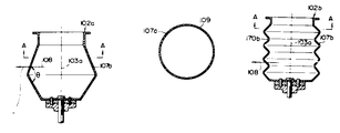
제 1a 도는 본 발명에 따른 제 1 실시예의 회전식 드럼의 구성도.1a is a block diagram of a rotary drum of a first embodiment according to the present invention.
제 1b 도는 제 1a 도의 A-A선에 따른 단면도.Fig. 1b or a cross sectional view along the line A-A of Fig. 1a.
제 1c 도는 본 발명에 따른 제 1 실시예의 다수 산형부를 갖는 회전식 드럼의 구성도.1c is a block diagram of a rotary drum having a plurality of peaks in the first embodiment according to the present invention.
제 2a 도는 본 발명에 따른 제 1 실시예의 회전 드럼식 세탁물 처리장치의 구성도.Figure 2a is a block diagram of a rotary drum type laundry treatment apparatus of a first embodiment according to the present invention.
제 2b 도는 세탁물 부착상황도.Figure 2b or laundry attached state.
제 3 도는 제 2a 도에 대한 정면도.3 is a front view of FIG. 2A.
제 4 도는 드럼의 산형각도와 함수율을 나타낸 시험결과 설명도.4 is a test result explanatory diagram showing the drum angle and the water content of the drum.
제 5 도는 드럼의 산형각도와 이탈력의 지표의 시험결과를 타나낸 설명도.5 is an explanatory diagram showing the test results of the index of the drum angle and the release force of the drum.
제 6 도는 본 발명에 따른 제 1 실시예와 종래장치에 의한 함수율 분표를 나타낸 설명도.6 is an explanatory diagram showing a moisture content fraction by a first embodiment and a conventional apparatus according to the present invention.
제 7a 도는 종래 탈수기의 측단면도.Figure 7a is a side cross-sectional view of a conventional dehydrator.
제 7b 도는 제 7a 도의 A-A 단면도.A-A cross sectional view of FIG. 7B or 7A.
제 8 도는 탈수기 시험시의 회전드럼을 평면에서 본 설명도.8 is an explanatory view in plan view of a rotating drum during the dehydrator test.
제 9 도는 종래장치에 의한 탈수시험 결과의 설명도.9 is an explanatory diagram of a result of a dehydration test by a conventional apparatus.
제 10 도는 본 발명에 따른 제 2 실시예의 주요부 단면도.10 is a sectional view of principal parts of a second embodiment according to the present invention;
제 11 도는 본 발명에 다른 제 2 실시예와 종래장치의 리넨 건조성능 비교도.Figure 11 is a comparison of the linen drying performance of the second embodiment according to the present invention and the conventional apparatus.
제 12 도는 종래 흡인식 건조장치의 단면도.12 is a cross-sectional view of a conventional suction drying apparatus.
제 13 도는 종래 흡인식 건조장치의 단면도.13 is a cross-sectional view of a conventional suction drying apparatus.
제 14 도는 제 13 도의 측면도.14 is a side view of FIG. 13;
제 15 도는 본 발명에 따른 제 3 실시예의 주요부 측단면도.15 is a side cross-sectional view of the main portion of a third embodiment according to the present invention.
제 16 도는 제 15 도의 정면도.FIG. 16 is a front view of FIG. 15. FIG.
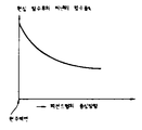
제 17 도는 본 발명에 다른 제 3 실시예와 종래 방식에 따른 건조장치의 수분 부착량과 건조시간과의 관계를 나타낸 선도.17 is a diagram showing the relationship between moisture deposition amount and drying time of a drying apparatus according to a third embodiment of the present invention and the conventional method.
제 18 도 및 제 19 도는 가열공기가 각각 상이한 방향으로 취입되는 예를 타나낸 설명도.18 and 19 are explanatory views showing an example in which the heating air is blown in different directions, respectively.
제 20 도는 드럼 중앙부만으로 취입되는 종래 방식에 있어서의 함수율 설명도.20 is an explanatory view of the moisture content in the conventional system blown only into the drum center portion.
제 21 도는 드럼 측벽부만으로 취입되는 종래 방식에 있어서의 함수율 설명도.21 is an explanatory view of the moisture content in a conventional system blown only by the drum side wall portion.
제 22 도 및 제 23 도는 실시예의 결합가능 예시도.22 and 23 illustrate exemplary combinations of embodiments.
본 발명은 예를들면 가정용 세탁기에 있어서의 탈수(세탁)조, 업부용 수세기, 드라이클리너, 혹은 기타 산업용의 각종 원심 탈수기에 적용되는 원심식 탈액조에 관한 것이다.The present invention relates to a centrifugal dewatering tank which is applied to various types of centrifugal dehydrators for, for example, a dehydration (washing) tank in a domestic washing machine, a centrifugal mill for a business unit, a dry cleaner, or other industries.
또, 가정용 및 산업용의 세탁, 탈수, 건조를 연속하여 행하는 전자동의 세탁, 탈수, 건조기에도 적용 가능한 것이다.Moreover, it is applicable also to the fully automatic washing | cleaning, dehydration, and a dryer which carry out washing, dehydration, and drying of household and industrial use continuously.
원심력을 이용하여 탈액하는 회전드럼식 탈액장치는 가정용세탁기, 업무용수세기, 유기용제를 사용하는 드라이클리너, 혹은 일반산업용의 원심식 탈수기 등의 어느 것을 채용하여도, 그 탈액에 관한 기본적 구성은 동등한 것이다. 예컨대 가정용세탁기를 들어 종래기술을 설명하면 다음과 같다.The rotary drum type liquid releasing device that uses a centrifugal force to remove liquid is the same as the basic constitution of the liquid releasing device, whether a domestic washing machine, a commercial water separator, a dry cleaner using an organic solvent, or a centrifugal dehydrator for general industry is employed. For example, a conventional washing machine will be described below.
즉, 종래기술에 있어서는 제 7a, b 도에 도시하는 것처럼, 탈수조(1)는 원형단면상을 가진 개구율이 10∼20%의 다공판 원주벽으로 되는 회전드럼(2)과 이 회전드럼(2)을 지지하여 이를 회전시키는 회전축(3)과, 동회전축(3)을 구동하는 모터(4)등으로 구성되어 있다. 9는 벽면(7)을 관통하는 구멍, 10은 탈수조(1)의 저부에 배설된 배수파이프, 11는 상기 모터(4)와 기대(機臺)와의 사이에 개재하는 방진 고무이다.That is, in the prior art, as shown in Figs. 7A and 7B, the dewatering tank 1 has a rotating
세탁을 끝낸 피세탁물(5)은 세탁조(도시하지 않음)에서 탈수조(1)로 옮겨 뚜껑(6)을 닫고 타이머 스윗치(도시하지 않음)등에 의하여 필요한 시간을 셋트하면, 회전드럼(2)이 모터(4)에 의해 고속회전하여 피세탁물(5) 중의 물이 회전드럼(2)의 회전중심축과 동심의 다공판 등으로 되는 원주벽면(7)에서 배출된다.After washing the finished laundry (5) from the washing tank (not shown) to the dehydration tank (1), close the lid (6) and set the required time by a timer switch (not shown), etc., the rotating drum (2) By rotating at a high speed by the motor 4, the water in the
본 발명자는 상기 종래기술에 대하여, 제 8 도에 도시하는 것과 같이 적층한 면포(5')를 원주벽면(7)의 내측에 벽면(7)에 따라 같은 두께로 셋트하여, 거의 탈수가 완료된 시점의 적층면포(5')의 한 장째의 함수율을 측정하였다. 그 결과, 제 9 도에 도시하는 것과 같이 원주벽면(7)에 가까운 면포의 함수율은 원주벽면(7)에서 떨어진 면포, 즉 회전축선에 가가운 면포의 약 2배의 함수율을 나타내었다.The present inventors set the laminated cloth 5 'laminated | stacked as shown in FIG. 8 with the same thickness according to the
이것은 제 8 도에 있어서 원주벽면(7)가 원심력이 작용하는 방향(8)이 직각으로 되어 있기 때문에, 면포(5')와 원주벽면(7)과의 사이에 보지된 물이 벽면을 따라 이동하는 것이 방해되어 배제할 수 없게 된다.This is because in Fig. 8, the
한편, 원주벽면(7)에서 떨어진 면포(5')중의 물은 면포층(5') 내의 모세관을 통하여 원심력의 작용방향(8)에 스무스하게 이동하기 때문에, 제 9 도에 도시하는 것과 같이 회전드럼(2)의 중심방향에 가가운 면포(5')의 함수율은 원주벽면(7) 근방의 면포(5')의 함수율 보다 낮게 된다.On the other hand, since the water in the cotton cloth 5 'away from the
또, 원주벽면(7)에 가까운 면포(5')의 함수율은 면포층(5')의 두께가 적으면 적을 수록 높게 되는 경향이 있다. 이것은 원주벽면(7) 근방의 면포층(5')을 원심력을 작용방향으로 누르는 작용을 하는 면포층(5')(원주벽면(7)에서 먼층)의 중량이 적어 짜는 효과가 감소하기 때문이라고 생각된다.Moreover, when the thickness of the cotton cloth layer 5 'is small, there exists a tendency for the moisture content of the cotton cloth 5' near the
이상 서술하여온 바와같이, 종래의 탈수장치는, 회전드럼(2)의 원주벽면(7)과 원심력이 작용하는 방향(8)이 직각으로 교차되기 때문에, 원주벽면(7) 근방의 피세탁물(5')의 배수가 충분히 행하여지지 않고 본래 원심력의 크기로 추측되는 탈수성능이 충분히 발휘되지 않는다고 하는 근본적 결함을 가지고 있는 것이다. 또 당연의 것이지만 결과적으로 탈수후의 피세탁물의 건조에 여분의 에너지와 시간이 허비되는 것으로 된다.As described above, in the conventional dewatering device, the
본 발명의 일차적인 목적은 이들의 점을 해결하기 위하여 구성된 것으로, 본래의 탈액성능이 발휘되고, 동시에 건조시에 있어서의 에너지의 감소 및 허비하는 시간의 단축화를 도모한 원심탈액장치를 제공하고자 하는 것이다.The primary object of the present invention is to solve these problems, and to provide a centrifugal dewatering device that exhibits the original dehydration performance and at the same time reduces the energy during drying and shortens the waste time. will be.
상기와 같은 일차적인 목적을 달성하기 위해 본 발명은 회전드럼 벽면이 원심력의 작용방향과 직교하지 않는 벽면으로서 구성되도록 하는 것으로서 드럼의 산형(山形) 각도를 90°내지 160°로 되는 각도로 하여, 이것을 상기 문제점의 해결수단으로 하는 것이다.In order to achieve the primary object as described above, the present invention is to be configured as a wall surface of the rotating drum wall is not perpendicular to the direction of action of the centrifugal force, the angle of the drum (90) to 160 °, This is to solve the above problem.
제 9 도에 도시하는 것과 같은 면포층에 있어서의 함수율의 분포, 즉, 원주벽면 근방에서 대단히 높은 함수율이 생기는 주원인은 기술한 바와같이 드럼회전 중심축에 대하여 원주벽면이 평행으로 늘어져 또 원심력의 작용방향과 원주벽면이 직각으로 교차한다는 데 있고, 그 때문에 배수불량이 된다. 따라서, 기본적으로는 드럼회전 중심축에 대하여 원주면의 전부 또는 그 일부를 평행하지 않은 형상으로 하든가, 혹은 원주벽면을 단순한 원형으로 하지 않고 원심력의 작용방향과 직각으로 교차하지 않는 것 같은 형상으로 하든지의 어느 수단을 채용하면 된다.The distribution of the moisture content in the cotton cloth layer as shown in FIG. 9, that is, the main cause of the extremely high moisture content in the vicinity of the circumferential wall surface, is as described above. The direction and the circumferential wall surface intersect at right angles, which results in poor drainage. Therefore, basically, all or part of the circumferential surface is not parallel to the drum rotation center axis, or the circumferential wall surface is not a simple circular shape and does not cross at right angles to the direction of action of the centrifugal force. Any means may be employed.
따라서, 이들의 수단을 채용함으로써, 드럼 벽면의 구멍에서 떨어진 위치에 놓인 액체는 원심력의 작용을 받아서 소정의 각도를 가진 벽면을 따라 흘러, 근방의 구멍에서 용이하게 배출되며 처리후의 피탈액물의 함수율을 대폭으로 감소시킨다.Thus, by employing these means, the liquid placed at a position away from the hole in the drum wall flows along the wall surface at a predetermined angle under the action of centrifugal force, and is easily discharged from the hole in the vicinity, thereby maintaining the water content of the effluent liquid after treatment. Significantly reduce
한편 산형각도를 작게하면 함수율을 작게할 수가 있지만 세탁물이 드럼에 착 달라붙는 현상도 감안하여야 하므로 세탁, 탈수, 건조를 1공정으로 행하는 기계의 경우는 이들의 점으로 보아서, 바람직한 각도가 있는 것을 알았다.On the other hand, if the angular angle is reduced, the water content can be reduced. However, the phenomenon in which the laundry adheres to the drum should be taken into consideration. .
이하, 본 발명의 제 1 실시예를 첨부도면에 의거하여 상술한다.EMBODIMENT OF THE INVENTION Hereinafter, 1st Embodiment of this invention is described in detail based on an accompanying drawing.
제 1 도 내지 제 2 도는 본 발명의 제 1 실시예를 도시하고 있다.1 to 2 show a first embodiment of the present invention.
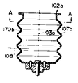
먼저, 제 1 도에 도시하는 예부터 설명하면, 동도(a)는 하나의 산형각도를 갖는 탈액조와 일부구동축의 측단면도, 동도(b)는 동도(a)의 A-A 화살표에서 본 단면도, 동도(c)는 다수의 산형각도를 갖는 탈액조와 일부구동축의 측단면도이다.First, starting from the example shown in FIG. 1, FIG. 1A is a side cross-sectional view of a desulfurization tank having a single angular angle and a partial drive shaft, and FIG. c) is a side cross-sectional view of a degreasing tank with several angles of angle and some drive shafts.
동도면에서 분명한 바와같이, 본 실시예에 관한 탈액조(102a)는 평단면에서는 어느 위치에서도 원형이지만, 회전축선(103a)을 포함하여 자른 종단면에서는 벽면(107a)과 회전축선(103a)이 소정의 각도가 되도록 구성되어 있다. 도시예의 경우에는, 탈액조(102a)의 전체가 높이 방향의 도중에 통이 불룩해진 항아리 모양으로 되어 있다.As is apparent from the figure, the degreasing tank 102a according to the present embodiment is circular in any position in the flat cross section, but the wall surface 107a and the rotation axis 103a are predetermined in the longitudinal section cut including the rotation axis 103a. It is configured to be an angle of. In the case of the example of illustration, the whole of the liquid removal tank 102a becomes a jar shape in which the cylinder was bulging in the middle of the height direction.
여기서, 원심력의 작용방향 F에 대하여, 탈액조(102a)의 벽면(107a)의 산형각도를 θ(제 1a 도에 도시)로 한다. 산형 각도 θ를 바꿔 면포층의 잔수율을 측정한 데이터를 제 4 도, 제 6 도에 나타낸다. 이것은 타월을 4분간, 350G로 탈수한 때의 값이다. 여기서, G는 회전가속도를 나타내며,Here, with respect to the action direction F of the centrifugal force, the ridge angle of the wall surface 107a of the dewatering tank 102a is θ (shown in FIG. 1A). 4 and 6 show data obtained by changing the ridge angle θ and measuring the residual ratio of the cotton cloth layer. This is the value when the towel was dehydrated at 350 G for 4 minutes. Where G is rotational acceleration,

로 산출할 수 있다.It can be calculated as
제 4 도에 도시하는 것처럼, 산형 각도 θ를 종래의 (180°)으로 할때 80%의 함수율의 면포층이 각도를 120°로 하면 65%로 되며, 15%의 물을 면포에서 빼낼 수가 있다. 더욱 이 각도를 60°로 하면 함수율은 60%로 되며, 종래보다 20%나 개선시킬 수 있다.As shown in Fig. 4, when the ridge angle θ is conventional (180 °), a 80% moisture content cotton cloth layer becomes 65% when the angle is 120 °, and 15% of water can be removed from the cotton cloth. . Further, when the angle is set to 60 °, the water content is 60%, which can be improved by 20% compared with the conventional art.
한편, 제 6 도에 도시하는 것처럼, 본 발명 장치에 의한 경우에는 탈수드럼의 벽면 가까이의 면포에 있어서도 탈수가 충분히 되어, 또한 회전드럼의 중심방향에 있어서의 탈수후의 함수율 분포에 큰 변동이 없고, 전체로서도 탈수효과가 증진되어 있다.On the other hand, as shown in Fig. 6, in the case of the apparatus of the present invention, dehydration is sufficient even in the cotton cloth near the wall surface of the dehydrating drum, and there is no great variation in the moisture content distribution after dehydration in the center direction of the rotating drum. The dehydration effect is also enhanced as a whole.
즉, 종래의 드럼에서는 드럼의 원주벽면과, 드럼 중심방향에서는 그 함수율의 차가 크고, 게다가 함수율이 높고, 드럼 원주벽면에서 90%, 드럼의 중심방향에서 65%로 되어 있다. 그러나, 드럼의 산형각도(θ)를 120°로 하면, 함수율은 드럼의 원주벽면 70%, 드럼의 중심방향 63%로 그 차가 작으며, 게다가 전체의 값이 작으므로 효율좋게 탈수되는 것을 알았다.That is, in the conventional drum, the difference in moisture content is large in the circumferential wall surface of the drum and the drum center direction, and the water content is high, and it is 90% in the drum circumferential wall surface and 65% in the center direction of the drum. However, it was found that when the drum angle θ of the drum was set to 120 °, the water content was small at 70% of the circumferential wall surface of the drum and 63% of the center direction of the drum.
한편, 제 5 도는, 드럼 산형각도 θ를 바꿨을때 타월 등의 면포층이 드럼 벽면에 부착하여 버리든지, 이 면포층을 떼는데 요하는 힘을 지표로 나타내고 있다.On the other hand, in FIG. 5, when the drum ridge angle θ is changed, a surface layer such as a towel adheres to the drum wall surface or the force required to remove the surface layer is represented as an index.
즉 산형각도 180°(종래의 드럼)일때, 드럼에 작용하는 원심력의 방향에 수직을 뗄때(수직으로 당김) 10정도의 힘, 원심력의 방향과 직각방향의 힘(옆에서 당김)으로 뗄때에는 드럼에는 물을 배출하기 위한 벽면을 관통하는 구멍(109a)이 있어 이 구멍속에 면직층이 들어가 있기 때문에 옆으로 당겨서는 떼기 어려우나 70정도의 힘으로 면포층이 떼어지는데 대하여, 산형각도를 작게 설정, 예를들면 60°로 하면 그것들은 각각 180, 240으로 되어, 지표 200 가까이 또는 이것 이상이 되기 때문에, 면포층은 드럼 벽면에 착 달라붙어 외부에서 힘을 가하지 않으면 떼어지지 않는 상태로 되어 실용적이 되지 않게 된다.That is, when the angular angle is 180 ° (traditional drum), when the drum is perpendicular to the direction of the centrifugal force acting on the drum (pulled vertically), the drum is about 10 degrees of force, and the force in the direction perpendicular to the direction of the centrifugal force (pulled from the side) There is a hole 109a penetrating through the wall for draining water, and it is difficult to pull it to the side because the cotton layer enters into the hole, but when the cloth layer is peeled off with a force of about 70, the ridge angle is set small. For example, at 60 °, they become 180 and 240, respectively, and close to or above the surface of the surface of 200, so that the cotton cloth layer sticks to the drum wall and does not come off unless it is applied from the outside, making it impractical. do.
따라서, 종래 드럼에 비하여 함수율의 개선을 행함과 동시에 드럼에 착 달라 붙은 것을 발생시키지 않기 위하여는 드럼 산형의 각도 θ를 90°내지 160°바람직하기는 120°내지 150°가 실용적이라는 것을 발견한 것이다.Therefore, in order to improve the water content as compared to the conventional drum and not to adhere to the drum, it is found that the angle θ of the drum mount is 120 ° to 150 ° to be practically 90 ° to 160 °. .
다음 제 2 도 및 제 3 도에서는 산형각도를 갖는 드럼식 세탁물 처리장치를 이용하여 세탁, 탈수, 건조의 각 공정을 연속하여 행하는 장치에 대하여 설명한다.Next, in FIG. 2 and FIG. 3, the apparatus which performs each process of washing, dehydration, and drying continuously using the drum type laundry processing apparatus which has an angular angle is demonstrated.
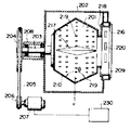
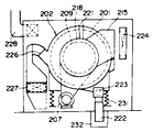
201 : 회전드럼 .... 원통상의 회전드럼이며 회전축(203)을 대략 수평으로 보지하면서 회전을 자유로이 하며, 회전축에 고착되어 있는 풀리(204), 구동용 벨트(205), 모터(207)에 고착되어 있는 구동용 풀리(206)의 전달경로로 구동된다. 드럼의 외통면(210)에는 통기, 통수용의 구멍(219)가 설치되어 있다.201: Rotating drum .... A cylindrical rotating drum, freely rotating while holding the
202 : 외동체 .... 드럼의 외부에 배치되어 있으며, 드럼회전축(203)을 지지하는 브래킷 및 베어링류로 되는 드럼서포트(208)를 한쪽에 고착하며, 다른 한쪽에는 드럼(201)내에 물, 증기, 가열공기 등을 공급하기 위한 취입부(209)가 고착되어 있다.202: Outer body .. The
203 : 회전축 .... 드럼(201)에 고착되어 있으며, 드럼 구동축으로서의 역할을 한다.203: Rotating shaft .. It is fixed to the
204 : 풀리 .... 드럼(201)을 구동하기 위한 풀리이며, 회전축(203)에 고착되어 있다.204: Pulley .... A pulley for driving the
205 : 벨트 .... 드럼(201)을 구동하기 위한 동력전달용이다.205: Belt .... For power transmission for driving the
206 : 풀리 .... 모터(207)에 고착되어 있으며, 모터의 회전력을 벨트(205), 풀리(204)를 통하여 드럼 회전축(203)에 전달한다.206: Pulley .... It is fixed to the
207 : 모터 .... 드럼(201)을 구동하기 위한 동력원이며, 회전수는 속도가변장치(230)에 의하여 설정된다.207: Motor .... is a power source for driving the
208 : 드럼서포트 .... 브래킷 및 베어링 류로 되며, 드럼의 회전축(203)을 지지하는 것.208: Drum support .... Supporting the
209 : 취입부 .... 드럼 외동체(202)의 입구부에 고착되어 있으며, 드럼(1)내에 물, 증기, 가열공기 등을 보내준다. 고리모양의 형상을 하고 있으며, 내주면에 개구부(220)가 있다. 드럼(201)의 외부에는 공급된 물, 증기, 가열공기 등의 가열매체가 새지 않을 것 같은 구조로 되어 있다.209: Blowing part .... It is fixed to the inlet part of the drum
210 : 외통면 .... 드럼(201)외주부이며, 외통면(210)에는 통기, 통수용의 구멍(219)이 설치되어 있다.210: Outer cylinder surface. The
외통면은 회전축 방향에 대하여 수직의 단면은 원형이며, 제 2 도와 같이 축방향 단면은 산형각도 θ이다.The outer cylinder surface has a circular cross section perpendicular to the direction of the rotation axis, and the axial cross section has a ridge angle θ as shown in the second diagram.
212 : 세탁물 .... 세탁, 탈수, 건조되는 타월, 샤쓰, 와이샤쓰 등.212: Laundry .... Washing, dehydration, drying towels, shirts, shirts, etc.
215 : 덕트 .... 제 1 도와 같이 드럼 외동체(202)의 측면에 고착되어 드럼(201)내에 가열공기를 보내준다.215: Duct .... It adheres to the side of the drum
216 : 도어 .... 리넨을 드럼(201)내에 투입할때는 열고, 세탁, 탈수, 건조의 공정 중은 닫혀 있다. 도어내면은 드럼의 외동체(202)의 취입부(209)와 밀착하고 있으며, 물, 증기, 가열증기 등이 외동체(202)의 외부에 새지 않는 구조로 되어 있다.216: Door .... When the linen is put into the
217 : 비이터 .... 드럼(201)의 외통면(210)에 복수개 취부된 산형상의 판이며, 드럼(201)의 회전에 의해 리넨을 윗쪽으로 들어올리는 효과를 가지고 있다.217: Viter .... It is a mountain-shaped board attached to the
218 : 실 .... 드럼 외동체(202)에 고착되어 있으며 드럼(201)의 외통면(210)과 슬라이드 하는 구조로 되어 있다. 취입부(209)에서 드럼(201)내에 공급되는 가열증기, 가열공기 등이 드럼(201)에 들어가지 않고 외동체(202)에 새는 것을 방지시키는 역할을 한다.218: Seal .... It is fixed to the drum
219 : 구멍 .... 드럼(201)의 외주면에 뚫려진 직경 수 mm의 구멍으로, 세탁공정에 있어서는 드럼(201)내와 외동체(202)내의 세탁수, 세제 등의 드나듦이 된다.219: Holes .... Holes having a diameter of several millimeters drilled into the outer circumferential surface of the
탈수공정에 있어서 드럼(201)은 고속회전 됨에 따라, 리넨에서 뿌리쳐진 수분이 이 구멍에서 외동체내로 배출된다.In the dehydration process, as the
건조공정에 있어서는, 드럼(201)내에 공급된 가열 공기는 리넨을 건조시키는 에너지를 드럼(201)내에 공급하여, 그후 이 공기는 그 구멍(219)에서 외동체(202)에 배출되어 탈액기 밖으로 배출된다.In the drying process, the heated air supplied into the
220 : 개구부 .... 취입부(209)의 내주면에 뚫여진 구멍이며, 이 구멍에서 드럼(201)내에 가열증기, 가열공기등이 공급된다.220: Opening hole .. A hole drilled in the inner circumferential surface of the blowing
221 : 급수관 .... 드럼(201)내에 세탁용의 물을 보내주는 배관이다.221: water supply pipe .... Pipe for sending washing water into the
222 : 배수관 .... 세탁공정의 도중에 또는 탈수공정에 있어서, 드럼 외동체(202)에서 물을 배수할때 이용되며, 댐퍼(223)의 개폐로 배수의 유무를 제어한다.222: Drainage pipe .... Used during the washing process or in the dehydration process, it is used to drain the water from the drum
223 : 댐퍼 .... 외동체(202)에서 배수할 때는 댐퍼(223)가 열려, 외동체(202)내의 세탁수, 탈수에 의하여 뿌리쳐진 물을 외동체(202)에서 탈액기의 배수흠(232)에 배출한다. 외동체(202)에서 배수하지 않을 때는 댐퍼(223)는 닫혀있다.223: Damper .... When draining from the
224 : 히터 .... 드럼(201)내에 가열공기를 공급할때, 도시하지 않은 블로워로 기외의 공기를 빨아들여 그 히터(224)로 실내의 공기를 가열하여 드럼(201)내에 보내준다. 그 히터는 증기 또는 가열 오일과 실내공기를 열교환 시키는 방식이 일반적이다.224: Heater .... When supplying the heating air into the
226 : 배기구 .... 드럼의 외동체(202)의 일부에 설치되어 있으며 외동체(202)내의 공기를 기외로 배출하기 위한 출구이다.226: Exhaust port .... It is provided in a part of the
227 : 린트필터 .... 드럼(201)내에서 배기된 공기중에는, 리넨의 실보무라지(린트)가 다량 포함되어 있다. 이 때문에 배기구(226)를 거쳐 배출된 공기를 린트 필터를 통과시키므로써 배기공기중에 포함되어 있는 린트를 붙잡는다.227: Lint filter .... The air exhausted in the
228 : 배기덕트 .... 린트필터(227)를 지나 린트가 제거된 배기를 기외로 배출하기 위한 덕트이다.228: Exhaust duct .... This is a duct for exhausting the exhaust from the
230 : 속도가변장치 .... 모터(207)의 회전속도를 조정하기 위한 장치이며, 세탁공정, 탈수공정 각각에 있어서 최적한 속도로 드럼(201)이 회전할 수 있도록 제어된다.230: speed variable device .... The device for adjusting the rotational speed of the
231 : 방진장치 .... 드럼(201) 및 외동체(202) 등은 그 방진장치의 위에 매달려 있다.231: Dustproof device .... The
232 : 배수홈 .... 배수관(222)에서 배출된 물을 실외로 유출시키기 위한 홈이다.232: drain groove .... The groove for outflow of water discharged from the
이와같이 구성된 제 1 실시예에 의하면(세탁)급수관(221)에서 물을 드럼(201), 외동체(202)내에 일정량 급수한다. 드럼(201)의 외주면에는 구멍(219)가 뚫려 있기 때문에, 드럼(201)내에 공급된 물을 구멍(219)을 통과하여, 외동체(202)내에 고여 저절로 드럼(201)내에 수위가 상승되어간다. 도시하지 않은 수위 검지 장치로 수위를 체크하여, 일정수위가 되면 급수를 정지한다. 도어(216)를 열어 리넨을 드럼(201)내에 공급한다. 모터(207)을 구동하여, 일정회전으로 드럼(201)을 회전시킨다. 드럼(201)의 회전은 정회전, 역회전을 반복하는 것이 리넨이 달라붙는 것을 방지하는데 효과적이다.According to the first embodiment configured in this way, the water is rinsed in the
도시하지 않은 세제, 조제공급장치에서 세제, 조제를 드럼(201)내에 공급하여 예비세척을 한다. 예비세척이 끝난 시점에서, 댐퍼(223)를 열어 예비세척에 사용한 세탁수를 배수관(222)을 지나 배수홈(232)에 배출하며, 일정시간 후 또는 예비 세척수의 배수가 완료한 것을 도시하지 않은 센스로 감지하여 댐퍼(223)를 닫는다.In the detergent and preparation supply device not shown in the drawing, detergent and preparation are supplied into the
다음같은 방식으로 세탁수를 드럼(201)내에 일정수위까지 급수하며, 또 도시하지 않은 세제,조제 공급장치에서 세제,조제를 드럼(201)내에 공급한다.The washing water is supplied to the
여기서, 도시하지 않은 증기 노즐을 작용시켜, 외동체(202)의 수중에 증기를 불어 넣어 세탁용의 물을 일정온도까지 승온시킨다. 드럼(201)의 회전은 속도 가변장치(230)의 제어에 의해 모터(207)의 회전수를 가변시킬 수가 있다. 세탁물을 비이터(217)로 드럼(201)의 윗쪽까지 들어올려, 낙하시킬때의 수면과의 충격에 의한 기계력, 더욱 이는 드럼(201)을 도시하지 않은 여진 장치에 의하여 여진시켜 리넨과 세탁수와의 상대속도를 강제적으로 크게 함으로써 세탁시간을 단축할 수가 있다.Here, a steam nozzle (not shown) is applied to blow steam into the water of the
이와같이 하여 온주중에서 씻어주고, 그후 드럼(201)의 회전을 중속회전으로 하여 리넨에 부착하고 있는 세탁수를 원심력으로 제거한다. 이때는 당연댐퍼(223)를 열어 세탁수를 배출관(222)에서 기외로 배수한다. 이후 댐퍼(223)을 닫아 물을 드럼(201)내에 다시 급수하여 행굼질 공정을 행한다. 행굼질 공정을 세탁공정과 같이 하여도 된다. 세탁수의 급수, 배수를 반복하는 행굼질 공정이 끝나면 다음은 탈수공정에 들어간다.In this way, washing is carried out in the hot water, and then the
[탈수][dehydration]
드럼(201)은 속도가변장치(230)의 제어에 의해, 드럼내주에 있어서 1∼1.5G의 가속도를 받는 회전으로 운전된다. 이것에 의하여 드럼(201)내에 들어가 있는 리넨은 드럼(201)의 내주면에 거의 균일하게 분포시킬 수가 있다. 이 상태로 된후, 드럼(201)은 고속회전되어, 리넨에 부착하고 있는 물은 원심력에 의하여 드럼(201)의 구멍(219)에서 외부로 배출되며, 이 물은 외동체(202)에서 배수관(222)을 지나 기외에 배출된다.The
여기서, 드럼의 산형각도 θ를 바꾸어 테스트한 결과는, 제 4-제 6 도에서 이미 서술한 바와같다.Here, the test result by changing the ridge angle θ of the drum is as described above with reference to FIGS.
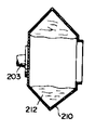
즉, θ를 60°로 하면 탈수후의 함수율은 60%로 되며, 종래보다 20%나 작은 값으로 할 수가 있다. 한편, 제 2b 도에 도시하는 것과 같이 세탁물(212)은 드럼의 외통면에 착 달라붙는 상태로 되며, 탈수공정이 끝난 시점에서도 자동적으로 낙하하지 않는 문제가 있는 것을 알았다. 이때문에 산형각도를 100°보다 크게 하였더니 탈수후의 세탁물은 약간의 충격, 예를들면 드럼 회전중에 도시하지 않은 브레이크 장치를 작동시켜 드럼을 급정지시키는 것 등으로 자유 낙하하는 것을 판명, 실용성이 확인되었다.In other words, when θ is set to 60 °, the water content after dehydration is 60%, which can be 20% smaller than in the prior art. On the other hand, as shown in Fig. 2B, the
또, 제 2 도와 같은 산형 드럼의 경우, 세탁물(212)은 탈수공정에 있어서 원심력에 의해 F방향으로 밀려 나와, 드럼 경위 큰 부분, 결국 외통면의 산의 정상부에 집중하고자 한다. 이 때문에, 탈수공정에서 통상문제로 되는 세탁물의 드럼내에서의 언밸런스 하중에 의한 진동은, 본 산형 드럼의 경우는 그 중심부 또는 이것에 가까운 곳에 언밸런스 하중이 발생하는 구조로 되기 때문에 탈수공정시의 진동을 작게 억제하는데 이상적이라는 것도 판명하였다.In addition, in the case of a mountain drum like the second degree, the
[건조][dry]
탈수공정이 종료 가깝게 되면, 히터(224)로 가열된 공기를 턱트(215), 취입부(209)를 경유하여 드럼(201)내에 공급하여 그대로 건조공정에 이행한다. 이때 세탁물(212)이 제 2b 도와 같이 드럼(201)내에 착 달라붙은 상태의 경우, 가열 공기를 드럼(201)내에 공급하여도 세탁물(212)을 균일하게, 단시간에 건조시키는 것은 불가능하다.When the dehydration step is near the end, the air heated by the
즉, 세탁, 탈수, 건조를 한 공정으로 행하기 위하여는, 탈수후의 세탁물(212)을 드럼(201)의 외통면(210)에서 사람손을 빌리지 않고 떼내는 것이 중요하다. 드럼의 회전수는 1G미만, 바람직하기는 0.7∼0.8G로 한다. 배기구(226)에 도시하지 않은 온도 또는 습도센스를 붙여 이것이 일정온도 또는 습도로 된 것을 감지하여 건조공정은 끝난다.That is, in order to perform washing, dehydration, and drying in a step, it is important to remove the
또한, 상기한 실시예에서는, 드럼의 산의 수가 하나인 경우에 대하여 설명하였으나 복수개의 경우에도 같은 효과를 달성할 수 있다. 또, 수세의 경우에 대하여 설명하였으나, 퍼클로로 에틸렌 등의 유기용제를 사용하는 드라이크리닝 기계에도 적용할 수 있는 것이다.In the above embodiment, the case where the number of acid of the drum is one has been described, but the same effect can be achieved even in a plurality of cases. Moreover, although the case of water washing was demonstrated, it is applicable also to the dry cleaning machine using organic solvents, such as perchloroethylene.
본 발명에 따른 제 1 실시예에 의하면, 원심탈액후의 세탁물의 함수율을 종래에 비하여 대폭으로 개선할 수 있음과 동시에, 드럼 내에서의 함수율의 분포를 균일하게 접근시킬 수가 있으며, 건조시간의 단축과 지나친 건조의 방지를 할 수가 있고, 게다가 드럼내에 세탁물이 착 달라 붙는 것을 방지, 드럼의 언밸런스 하중을 드럼의 중심 근처에 특정할 수 있는 등 여러가지의 뛰어난 효과를 나타낼 수 있는 것이다.According to the first embodiment according to the present invention, the water content of the laundry after centrifugal dehydration can be improved significantly compared to the conventional one, and the distribution of the water content in the drum can be approached uniformly. Excessive drying can be prevented, and besides, laundry can be prevented from sticking to the drum, and an unbalanced load of the drum can be specified near the center of the drum.
다음으로는 본 발명에 따른 제 2 실시예에 대하여 설명한다. 세탁업계에서는 호텔, 병원 등으로 받아오는 이미 사용해서 더러워진 타월, 쉬이츠, 싸개와 같은 물건(이하 리넨이라 부른다)을 처리해서 청결한 리넨으로 호텔, 병원 등에 출하하고 있다. 처리의 공정으로는, ①세탁, ②탈수, ③건조, ④마무리로 나뉘고, 타월등 완전건조하는 것을 ①∼③의 공정, 쉬이츠, 싸개처럼 마무리작업이 필요한 것은 ①∼④ (단, 공정 ③은 단시간)의 공정으로 하고 있다.Next, a second embodiment according to the present invention will be described. In the laundry industry, items such as towels, sheets, and wrappers (called linen), which have already been used and received at hotels and hospitals, are processed and shipped to hotels and hospitals as clean linens. The process of treatment is divided into ① laundering, ② dehydration, ③ drying, and ④ finishing, and complete drying such as towels is required for the finishing process such as the process of ① ~ ③, sheets, wrappers, etc. Is a short time) process.
종래의 기계로는 먼저 세탁, 탈수를 하고 그 뒤 세탁물을 다른 건조기에 옮겨 건조공정을 끝내는 방식이 일반적이다. 세탁, 탈수를 연속해서 하는 기계는 회전드럼의 외주(外周)가 다공판(多孔板)으로 되어 있고, 회전 드럼안에 리넨을 들어올리기 위한 소위 비이터가 복수개 장치돼 있고, 드럼의 회전에 의해 이 비이터로 리넨이 위로 들어올려지고, 낙하할때의 충격 및 세제, 온도 등의 화학적인 힘 등에 의해 세탁되는 것이 일반적이다. 세탁공정이 끝나면, 이 회전드럼이 고속회전되고, 원심력에 의해 리넨에 배어 있던 물이 털려나서 탈수된다. 탈수공정이 끝나면, 작업자는 이 세탁, 탈수기를 정지하고, 리넨을 대차(坮車)에 옮겨 실은 다음 안에 세탁, 탈수된 리넨을 투입하고, 그 뒤 회전드럼식 건조기의 드럼안에 세탁, 탈수된 리넨을 투입하고, 그 뒤, 열풍을 드럼안으로 불어넣음으로써 리넨을 건조시킨다. 이들 리넨에는 상술한 바와 같이 타월등 완전 건조를 요하는 리넨과 쉬이츠, 싸개 등 반건조로 다음의 다리미질 공정을 이행하는 리넨이 있어, 리넨의 종류에 따라 건조시간이 다르고, 이에따라 건조시간이 선택된다.Conventional machines generally wash, dehydrate, and then transfer the laundry to another dryer to complete the drying process. In the machine for continuous washing and dehydration, the outer periphery of the rotating drum is made of a perforated plate, and a plurality of so-called beaters for lifting the linen in the rotating drum are provided. The liner is lifted up with a beater, and it is generally washed by the impact of falling and by chemical forces such as detergent and temperature. After the washing process, the rotating drum is rotated at high speed, and the water soaked in the linen is dehydrated by centrifugal force. After the dehydration process, the worker stops the washing and dehydrator, transfers the linen to the trolley, loads the washed and dehydrated linen inside, and then washes and dehydrates the linen in the drum of the rotary drum dryer. The linen is then dried by blowing hot air into the drum. These linens have linens that perform the following ironing process by semi-drying linens such as towels, sheets, and wrappers that require complete drying as described above, and the drying time varies depending on the type of linen, and thus the drying time is selected accordingly. do.
이상 세탁, 탈수와 건조를 따로 다른 기계로 하는 일반적인 종래기술에 대해 말했지만, 특수한 예로 세탁, 탈수와 건조를 1대의 기계로 연속해서 하는 이른바 세탁, 탈수, 건조기도 시판되고 있다.As mentioned above, although the conventional prior art which separates washing, dehydration, and drying into a separate machine was mentioned, what is called a laundry, dehydration, and a dryer which performs washing, dehydration, and drying in one machine in a special example is also marketed.
이런 형태의 기계는 세탁, 탈수, 건조가 연속해서 행해지기 때문에 분리형에서 처럼 도중에 작업자가 리넨을 운반할 필요는 없지만 장치면에서는 다음과 같은 제약이 생겨, 상품으로 널리 보급되지 않고 있는 것이 현실이다.Since this type of machine is washed, dehydrated, and dried continuously, it is not necessary for a worker to carry linen on the way as in a separate type, but the following limitations arise in terms of equipment, and it is not widely used as a commodity.
즉, ① 세탁, 탈수 때의 젖은 세탁물의 하중에 견디기 위해 건조 단능기(單能機)에 비교해 높은 강(剛)성이 필요해 코스트가 높아진다.That is, in order to withstand the load of wet laundry at the time of washing and dehydration, high rigidity is needed compared with a dry functional group, and cost becomes high.
② ① 항과 같은 이유로 드럼의 다공(多孔)판 개구율(開口率)은 기껏 30%가 한도가 되며, 건조 단능기의 40∼60%와 비교해서 통기(通氣)율이 낮고 건조시간이 그만큼 길어진다. 그럼 여기서, 본 발명에 따른 제 2 실시예의 대상기술인 종래의 건조기술, 특히 열풍의 흐름에 대해 도면으로 설명한다.② For the same reasons as in ①, the opening ratio of the perforated plate of the drum is at most 30%, and the air permeability is low and the drying time is long as compared with 40 ~ 60% of the dry functional group. Lose. Now, the conventional drying technique, in particular, the flow of hot air, which is the target technique of the second embodiment according to the present invention, will be described with reference to the drawings.
제 12 도 내지 제 14 도는 다같이 종래의 건조기 혹은 세탁, 탈수, 건조기의 회전드럼 둘레의 열풍의 흐름을 보여주는 모델 도면이다. 먼저, 제 12 도에 대해 설명한다. 51은 드럼, 52는 스티임 째켓 등으로 이뤄지는 에어히이터, 53은 리넨, 54는 열풍(55')을 빨아들이고 계외(系外)로 배출하기 위한 흡기(吸氣) 블로워다.12 to 14 is a model diagram showing the flow of hot air around the rotating drum of the conventional dryer or washing, dehydration, dryer as a whole. First, FIG. 12 is explained. 51 is an air heater made of a drum, 52 is a steam jacket, 53 is linen, 54 is an intake blower for sucking hot air 55 'and discharging it out of the system.
이 방식에서는 드럼(51)의 상방에 만든 공기 취입구(取入口)(56)로부터 에어히이터를 통과한 열풍(55')이 흡수되고, 드럼 외주벽을 따라 흐르면서 드럼(51)의 다공부를 통해 드럼(51) 안으로 들어가 리넨(53)과 접촉한 다음, 드럼(51) 하부의 배기구(57로부터 흡기 블로워(54)를 경유해서, 계외로 배출되지만, 그 특징은 흡입방식에 고유한 유선(流線)이 갖춰진 이른바 정류(整流)열풍이 돼있는 점이다.In this system, the hot air 55 'passing through the air heater is absorbed from the
다음 제 13 도에 대해 설명한다. 제 13 도에 나타낸 장치도 그 구성은 제 12 도의 것과 거의 동일하지만, 제 14 도의 측단면에서 명백한 바와 같이 드럼(51) 상의 열풍분배 박스(58)에 의해, 열풍(55')을 보다 적극적으로 드럼(51)의 상반(上半) 전면부로부터 드럼(51)의 내부에 균일하게 흘리려는 것으로, 제 12 도에 나타낸 경우 보다도 정류효과가 한층 더 확연히 나타나게 된다.Next, FIG. 13 will be described. The arrangement shown in FIG. 13 is also substantially the same as that in FIG. 12, but the hot
이상 서술해온 바와 같이 종래에는 흡기 블로워(54)에 의한 흡입방식이 주류로 되어 있고, 드럼안의 정류된 열풍(55') 속을 드럼(51)의 회전에 의해 들어올려진 리넨(53)이 부유(浮遊)함으로써 건조를 행하도록 되어 있다.As described above, conventionally, the suction method by the
종래는 열풍을 흡인방식으로 빨아들이고 있고, 드럼안으로 통과하는 열풍은 소위 정류 열풍이 되어, 그 평균풍속은 1∼2m/초, 최대의 경우라도 5m/초 미만으로 돼 있다.Conventionally, hot air is sucked in by a suction method, and the hot air passing into the drum is a so-called rectified hot air, and the average wind speed is 1 to 2 m / sec, even at maximum, less than 5 m / sec.
때문에, 드럼 내에서 리넨을 유효해서 열풍에 접촉시키려면, 드럼의 회전수 범위를 중력가속도 표현으로 0.7∼0.8G에 한정하고, 정류열풍 중에 될 수 있는 한 장시간 부유시킬 필요가 있다. 이와 관련하여 1G부근 또는 1G를 넘으면 리넨이 드럼 내주벽에 부착고정해서 건조가 현저히 저해된다. 바꿔 말해 드럼 하부의 리넨 덩어리가 드럼의 회전에 따라 열풍중에 부유하는 찬스는 0.7∼0.8G때가 최대고, 그 이상의 회전에서는 오히려 저하하게된다. 더욱, 열풍의 평균 속도가 1/2m/초로 작기 때문에, 리넨과의 상대속도를 크게할 수 없고, 미크로 적으로는 리넨에서 증발한 수증기의 제거한 그만큼 더디어진다.Therefore, in order to make linen effective in contact with hot air in the drum, it is necessary to limit the rotational speed range of the drum to 0.7 to 0.8 G in terms of gravity acceleration, and to float for as long as possible in the rectified hot air. In this connection, when around 1G or more than 1G, linen adheres to the drum inner circumferential wall and drying is significantly inhibited. In other words, the chance that the linen mass at the lower part of the drum floats in the hot air as the drum rotates is 0.7 to 0.8G, and the rotation is lowered at further rotations. In addition, since the average speed of hot air is small at 1/2 m / sec, the relative speed with linen cannot be increased, and it is slower as much as the removal of water vapor evaporated from linen.
이상의 이유에서 종래의 흡인방식에 의한 건조로써는 통상 30∼40분이 평균 건조시간으로 돼 있고, 이것을 대폭단축할 수 있는 건조장치의 개발이 강하게 요망돼 있는 점이 현상이다.It is a phenomenon that the conventional drying method by the suction method is 30-40 minutes as an average drying time for the above reason, and the development of the drying apparatus which can greatly shorten this is strongly desired.
본 발명에 따른 제 2 실시예는, 종래의 기계로서는 리넨을 정류열풍속에 부유시키기 위한 드럼 회전수 범위에 제약이 있다는 점 및 열풍의 드럼 내 평균속도가 1∼2m/초로 작아서 리넨과의 상대속도를 크게 낼 수 없다는 점 두가지에 착안해서, 이것들을 근본적으로 해결하려는 목적에서 개발된 것이다.According to the second embodiment of the present invention, the conventional machine is limited in the range of drum rotation speed for floating the linen in the rectified hot wind speed and the relative speed with the linen as the average speed of the hot wind in the drum is small to 1-2 m / sec. It was developed with the intention of solving these fundamentals, focusing on two things that can't be made large.
본 발명에 따른 제 2 실시예는 상기의 목적을 달성키 위해, 회전드럼 안에서 세탁물을 적어도 건조처리를 가능케 하는 세탁물의 드럼식 처리장치에 있어서, 상기 회전 드럼 상부에 위치해서 개구하는 열풍 불어넣기 취입 노즐의 배설을 구성으로 한다.According to a second embodiment of the present invention, in order to achieve the above object, a drum type processing apparatus for laundry that enables at least drying processing of laundry in a rotating drum, the hot-air blowing blow nozzle positioned on the rotating drum to be opened. Let's excrete.
이것을 다시 설명하면, 열풍의 흐름을 종래의 흡인(빨아들이는)방식에서 취입(불어넣기) 방식으로 바꾸고, 노즐에 의해 풍속을 5m/초 이상의 분류(噴流)로 만들어 드럼의 다공판을 거쳐, 드럼의 회전에 의해 드럼 안에서 들어올려진 리넨에 직접 열이 작용하도록 하는 구조로 했다. 구체적으로는 노즐 개구부의 배설방향을 예컨대 시계의 단침으로 9시에서 12시, 혹은 12시에서 3시의 각도로 드럼 중심을 향해 분류를 불어넣게 하는 것이다.In other words, the flow of hot air is changed from the conventional suction (sucking) method to the blowing (blowing) method, and the wind speed is divided into a flow rate of 5 m / sec or more by a nozzle and passes through the porous plate of the drum. It was designed to allow heat to act directly on the linen lifted in the drum by the rotation of the drum. Specifically, the discharge direction of the nozzle opening is blown into the drum center at an angle of 9 to 12 o'clock, or 12 to 3 o'clock, for example, with a clock hand.
본 발명에 따른 제 1 실시예에 있어서는 상기 구성을 갖췄기 때문에 드럼 다공판을 거쳐 분류열풍이 직접 리넨에 작용하게 되고, 리넨과 열풍과의 상대속도를 크게 하고, 주위의 수증기를 신속히 제거하기 때문에 리넨으로부터의 수분의 증발속도가 커진다. 즉 건조시간이 단축된다.In the first embodiment according to the present invention, because of the above configuration, the classification hot air directly acts on the linen via the drum perforated plate, increases the relative speed between the linen and the hot air, and quickly removes the surrounding water vapor. The rate of evaporation of the water from the membrane increases. In other words, the drying time is shortened.
또, 드럼 회전율 1G가까이로 해서 리넨이 드럼 내주벽에 달라붙게 되더라도 상기 취칩 노즐의 분류효과에 의해 리넨을 드럼 중심부로 불어날릴 수가 있기 때문에, 종래와 같이 드럼 회전범위를 0.7∼0.8G에에 한정할 필요가 없고 예컨대 0.8∼1.2G로 하여 드럼내 리넨을 교반시키는 빈도를 크게할 수가 있다.In addition, even if the linen adheres to the drum inner circumferential wall near the drum rotation rate of 1G, the linen can be blown to the center of the drum due to the jetting effect of the chip chip nozzle, so the drum rotation range should be limited to 0.7 to 0.8G as in the prior art. It is not necessary to increase the frequency of stirring the linen in the drum, for example, at 0.8 to 1.2 G.
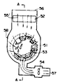
이것은 건조 반(班, 얼룩)의 방지 및 건조시간의 단축에 대해 큰 효과가 있다. 이하 본 발명에 따른 제 2 실시예의 구성을 첨부도면에 의거 상세히 설명한다. 제 10 도에 본 발명에 따른 제 2 실시예의 단면을 나타낸다. 이 도면에 있어서, 그 주요부는 처리조(處理槽)(512) 및 닥트(duct)(511)로써 이뤄지며 처리조(512)내에는 처리조(512)에 설치한 도시하지 않는 축받이를 통해 회전을 가능케한 다공판으로서 이뤄지는 회전드럼(521)이 수납돼 있다.This has a great effect on preventing drying spots and shortening of drying time. Hereinafter, the configuration of the second embodiment according to the present invention will be described in detail with reference to the accompanying drawings. 10 shows a cross section of a second embodiment according to the invention. In this figure, the main part consists of the
회전 드럼(521)은 도시하지 않는 모우터 및 제어장치에 의해 필요한 회전이 주어진다. 처리조(512)에는 열풍(505)의 입구로서의 취입노즐(509)과 출구로서의 배기구(507)가 배설돼 있지만, 부착각도는 전자가 시계의 단침으로 9시에서 12시, 또는 12시에서 3시에 상응하는 각도로 드럼 중심을 향해 개구되고, 후자는 상기 노즐(509)에 대응해서 각각 시계 단침의 2시에서 6시, 또는 6시에서 10시 각도로 부착되는 것이 바람직하다. 닥트부(511)에는 공기의 흐름방향을 따라 순차로 공기 취입부(506), 취입(吹入) 블로워서(504), 스티임 째켓 등에 의해 가열되는 에어히이터(502) 및 처리조(512)에 개구하는 취입노즐(509)이 배설돼 있다. 또한 취입노즐(509)의 개구면적은 열풍분류 속도가 적어도 5m/초 이상이 되도록 설계돼 있다.The
다음에 그 작용을 설명한다.Next, the operation will be described.
① 도시하지 않는 도어(문)로 드럼(521)안에 투입된 리넨(503)은 드럼(521)이 도시하지 않는 모우터 및 제어장치에 의해 화살표(510)의 방향으로 0.7∼1.2G 사이에서 회전함으로써 드럼(521)안에서 들어올려지고, 드럼(521)내주벽을 따라 운동한다.(1) The
② 한편, 취입 블로워에 의해 빨아들여진 공기는 에어히이터(502)에 의해 110∼140℃로 가열되고, 다시 취입 노즐(509)에 의한 5m/초 이상의 분류 열풍(505)이 돼서 드럼(521)의 다공판을 거쳐 리넨(503)에 직접 불어대게 된다.(2) On the other hand, the air sucked in by the blow blower is heated to 110 to 140 ° C by the
③ 분류열풍(505)에 의해 드럼(521)의 내주벽(다공판) 가까이의 리넨(503)은 드럼(521) 중심부를 향해 불어 날려진다.(3) The
④ 리넨(503)에 불어댄 열풍(502)은 드럼(521)의 회전에 의해 드럼(521) 내주벽에 달라붙은 리넨(503)층을 관통해서 배기구(507)로 배출된다.(4) The
⑤ ①∼④ 공정이 드럼(521)의 회전에 의해 연속적으로 행해지고, 리넨(503)의 건조가 진행한다.5) Steps 1 to 4 are continuously performed by the rotation of the
이상의 공정이 본 발명에 따른 제 2 실시예의 기본 공정이지만, 이하 본 발명의 포인트에 대해 더욱 상세히 설명한다.Although the above process is the basic process of the second embodiment according to the present invention, the points of the present invention will be described in more detail below.
제 11 도는 종래의 흡인식에 의한 정류 열풍건조와 본 발명에 의한 취입식 분류 열풍 건조와를 동일 풍량으로서 비교한 것이다. 이 그림에서, 본 발명에 의하면 종래와 비교해서 건조시간을 1/2∼1/3로 단축 가능하다는 것을 알 수 있다. 이것은, 공학적으로는 건조속도를 R, 열풍의 중량속도를 G로 할때 R=KG0.7-0.8의 관계가 있고, 열풍과 리넨과의 상대속도, 즉 G를 크게하는 것이 곧 R을 크게 하는 것이 된다.FIG. 11 compares the conventional rectified hot air drying by suction and the blown-type hot air drying according to the present invention as the same amount of air. In this figure, it can be seen that according to the present invention, the drying time can be shortened to 1/2 to 1/3 compared with the prior art. In engineering, this is related to R = KG 0.7-0.8 when the drying speed is R and the weight speed of hot air is G. Increasing the relative speed of hot air and linen, that is, G, increases R. do.
또 리넨(503)의 평면상 건조에서 병행류(竝行流) 열풍을 분류열풍으로 하는 것으로써 10배의 건조속도가 얻어진다는 보고예(기초섬유 공학(V))가 소개돼 있고, 열풍의 분류화가 리넨 건조의 고속화에 극히 유효하다는 것을 알 수 있다.In addition, a report example (basal fiber engineering (V)) has been introduced in which a drying rate of 10 times can be obtained by using a parallel flow hot air as a classification hot air in the planar drying of
다음으로 드럼(521)이 회전수에 대해서는, 종래 방법에서는 상술한 바와 같이 0.7∼0.8G가 적당하다고 돼 있다.Next, about the rotation speed of the
드럼(521)의 회전수는 드럼 내의 리넨(503)을 교환 또는 갈아넣는 빈도에 직접 영향을 미치는 것으로, 크면 클수록 유리하지만, 종래의 방법으로 0.7∼0.8G가 상한으로 돼 있다. 이것은 0.8G이상으로 하면 리넨(503)이 드럼(521)내주벽 근방에 모여, 리넨(503)이 드럼(521)의 최상부에 위치해도 중력에 의해 낙하하기가 어려워지기 때문이며, 리넨(503)의 교반 효과는 역으로 감소하면 된다.The number of revolutions of the
그러나 본 발명에는 취입 노즐(509)로 부터의 분류에 의해 드럼(521) 내주벽에 부착해 있는 리넨(503)을 강제적으로 드럼(521)의 중심부로 불어 날릴 수 있기 때문에 회전수를 종래처럼 제한할 필요가 없고 1G을 넘는 회전수라도 드럼 회전수 증가에 대한 리넨 교반효과를 십분 기대할 수 있게 된다.However, in the present invention, since the
이상 서술해온 바와 같이, 취입 블로워(504)와 취입 노즐(509)의 조합에 의한 열풍(505)의 분류화에 의해, 종래에는 전혀 기대할 수 없었던 건조시간의 대폭단축 및 시간단축에 의한 에너지 절약(시간과 대략 같은 비례)이 가능해진다. 더구나 드럼의 사이즈에 따라 결정되는 정격(定格) 부하량(JIMS)을 1∼2할 넘긴 리넨 양일지라도 단시간에, 또 균일하게 건조시키는 것이 가능해진다.As described above, by the classification of the
또한, 배기구(507)의 배설위치는 상술한 바와 같이 취입노즐의 배설위치와 관련해서 고려할 필요가 있다. 이것은 일단 리넨(503)에 분류가 돼서 불어닥친 열풍(505)이 반드시 다른 리넨 층을 통과해서 배출되도록 배려하는 것이며, 이미 기술한 이외의 각도에서는 열풍의 소오트 페스(short pass)에 의해 건조속도, 효율이 둘다 저하한다. 이 경우 드럼의 회전방향도 중요한 요인이 된다.In addition, the location of the exhaust port 507 needs to be considered in relation to the location of the injection nozzle as described above. This is to make sure that the
예컨대, 제 10 도에 표시한 바와 같이 10시의 단침 각도로 분류를 취입받을 경우의 최적 배기구 부착각도는 3시간에서 5시의 단침 각도지만, 이 경우의 드럼(521)의 회전방향으로서는 반시계 바늘 방향에 한정되고, 시계바늘 방향으로 도는 드럼(521)의 회전방향에서는, 최적 배기구(507)의 부착각도는 5시에서 6시의 단침각도가 최적이 된다. 이것은 2시의 단침 각도에서 분류를 불어넣었을 경우에도 좌우대칭의 관계에서 상기의 기재를 전혀 역으로 읽으면 된다는 것을 의미한다. 분류의 불어대는 각도를 9시에서 12시의 단침각도의 범위로 해도 대략 10시의 단침각도와 동등한 건조성능이 얻어지지만, 이 범위를 넘기면 드럼(521)내의 공간에 유효하게 리넨(503)을 날아 흘러지게 하는 것이 곤란해져, 건조능력이 저하한다.For example, as shown in FIG. 10, the optimum angle of attaching the exhaust vent when the jet is blown in at a small needle angle of 10 o'clock is a small needle angle of 3 hours to 5 o'clock, but the counterclockwise direction is the rotational direction of the
또한, 12시에서 3시의 단침각도로부터의 분류 취입도 전혀 동일하다. 이상에서 상세히 설명한 바와 같이 본 발명에 의하면 다음에 드는 훌륭한 효과를 발휘한다.Moreover, the classification blow-up from the short needle angle of 12 o'clock to 3 o'clock is also the same. As described in detail above, the present invention achieves the following excellent effects.
(1) 드럼식 건조장치에 있어서, 종래의 리넨 건조 소요시간 30∼40분(정격부하시)를 1/2∼1/3로 단축할 수 있으며, 겸해서 같은 율로 에너지 절약이 가능하다.(1) In the drum type drying apparatus, the conventional
(2) 분류가 리넨에 직접 작용하기 때문에 풀어주는 효과가 생겨 리넨이 부드럽게 마무리된다.(2) As the sorting acts directly on the linen, it has a releasing effect and the linen finishes smoothly.
(3) 분류 및 1G 근방의 고속드럼 회전을 가능케 한 것에 의해 정격 부하량을 1∼2할 넘겨도 고속으로 그리고 균일하게 건조시킬 수가 있다.(3) The high speed drum rotation near 1G can be used to achieve high speed and uniform drying even if the rated load exceeds 1 to 20%.
다음으로 본 발명에 따른 제 3 실시예에 대하여 설명한다. 종래의 건조방법은 회전드럼 속에 세탁, 탈수된 리넨을 투입하고, 그 뒤 드럼 내주(內周)에 있어서의 원심가속도가 중력가속도 1G 이하의 회전속도로 드럼을 회전시키면서, 리넨을 드럼안에 고착돼 있는 비이터 등으로 들어올려, 리넨을 드럼 상방으로부터 자중낙하시키면서 건조가열공기(이하 열풍이라 부름)를 드럼안으로 불어넣음으로써 리넨에 열풍을 불어대서 건조시키고 있다.Next, a third embodiment according to the present invention will be described. In the conventional drying method, the linen is fixed in the drum while washing and dehydrating linen is put in a rotating drum, and then the centrifugal acceleration in the drum's inner circumference is rotated at a rotational speed of 1 G or less. A hot air is blown into the linen by blowing dry heated air (hereinafter referred to as hot air) into the drum while lifting the linen by weight from above the drum.
이 때문에 드럼의 용적은 드럼안에서 빨래가 자유로이 움직일 수 있는 공간이 필요해지고, 일반적으로 세탁, 탈수공정에서의 필요용적의 약 2배의 공간이 필요해진다. 따라서 세탁, 탈수, 건조의 각 공정을 연속해서 1개의 드럼에서 처리하는 전자동의 세탁, 탈수, 건조기의 드럼용적은 세탁, 탈수기 용적의 2배가 되고, 기계가격과 기계 싸이즈를 크게하는 원인이 돼 있다.For this reason, the volume of a drum requires the space which a laundry can move freely in a drum, and generally the space of about twice the required volume in a washing | cleaning and a dehydration process is needed. Therefore, the drum volume of automatic washing, dehydration and drying machine which processes each process of washing, dehydration and drying in one drum in a row doubles the volume of washing and dehydrator, causing the machine price and machine size to increase. .
여기서, 업무용 세탁기계의 표준 부하량의 계산기준(사단법인 일본산업기계공업회)을 설명하면,Here, the calculation standard (Japan Industrial Machinery Industry Association) of the standard load amount of a commercial washing machine system is explained.
표준 부하량 α=f. 1/4πD2LStandard load α = f. 1 / 4πD 2 L
f : 부하율 KG/㎥f: Load rate KG / ㎥
세탁탈수기 : 45+30DLaundry Dehydrator: 45 + 30D
건조기 : 40Dryer: 40
D : 드럼 내동의 내경 mD: inner diameter of drum inner cavity m
L : 드럼 내동의 내장 mL: Built-in drum inner m
드럼 내동의 내장(內長)은, 빨래를 넣었다 뺏다 할 수 있어야 한다는 제약 칫수가 있고, 통상 부하량 30kg 경우에 1.0∼1.3이다. 이때 세탁탈수기에 대해, 건조기 용적은 1.875∼2.1이 된다.The internal organs of the drum inner cavity have a constraint that the laundry can be put in and out, and is usually 1.0 to 1.3 when the load is 30 kg. At this time, the dryer volume is 1.875 to 2.1 for the laundry dehydrator.
종래의 세탁탈수건조기에 있어서의 건조공정에 있어서, 상기 표준부하량에 대해 과대한 부하를 드럼 속에 투입하면 세탁물이 드럼안에서 자유로이 움직이지 못하기 때문에, 드럼내의 부위에 다라 세탁물의 건조불량이 야기됨과 아울러, 건조시간이 부하량에 비해 장시간 필요해지는 것이 확인돼 있다. 또 건조불균일은 세탁물을 일부 지나치게 건조시켜 그 수명을 현저하게 단축하는 원인도 된다는 등의 문제가 있었다.In the drying process of the conventional laundry dehydration dryer, if an excessive load is put into the drum with respect to the standard load, the laundry cannot move freely in the drum, resulting in poor drying of the laundry depending on the part of the drum. It has been confirmed that the drying time is required for a long time compared to the load. Moreover, there existed a problem that dry nonuniformity caused the laundry to dry too much, and also shortened the life significantly.
본 발명에 따른 제 3 실시예는 드럼내에 표준부하량 이상을 부하시켰을 때에도, 드럼내의 세탁물을 균일하게 건조하는 것, 건조시간을 단축할 수 있는 것 등의 효과를 발휘하는 드럼식 건조기를 제공하려는 것이다.The third embodiment according to the present invention is to provide a drum type dryer having an effect of uniformly drying the laundry in the drum, shortening the drying time, and the like, even when more than a standard load is loaded in the drum.
이를 위해 본 발명은, 다공을 가진 회전드럼 안에 투입된 의류 등을 세탁, 탈수, 건조 또는 그냥 건조시키는 장치에 있어서, 회전드럼을 횡형으로 축받침하고, 동 회전드럼의 축방향 및 외통방향으로부터 건조가열 공기를 취입하고 이 취입방향을 일정시간 마다 번갈아 절환하도록 한 것이며, 이것을 과제해결의 수단으로 하는 것이다.To this end, the present invention, in the device for washing, dehydration, drying or just drying the clothes put into the rotating drum having a porous, supporting the rotating drum horizontally, and dry heating from the axial direction and the outer cylinder direction of the rotating drum The air is blown in and the blowing direction is alternated every fixed time, which is used as a means for solving the problem.
드럼의 외통방향으로부터 열풍을 취입함으로써, 세탁물의 외주로부터 내주부로 열풍이 통과하여 가열됨으로써, 세탁물의 수분 부착량은 외주부 편이 건조하기 쉽다. 다음으로 드럼의 축방향으로부터 열풍을 취입하면, 드럼의 중앙부로부터 외주부에 걸쳐 열풍이 통과하므로 드럼중앙부 편이 건조하기 쉽고 수분 부착량이 적어진다. 이렇게 취입방향을 교대하도록 조합함으로써 드럼내의 세탁물을 단시간에, 게다가 균일하게 가열건조시킬 수가 있다.The hot air flows from the outer circumference of the drum to the inner circumferential portion by heating the hot air, thereby heating the water. Next, when hot air is blown in from the axial direction of the drum, hot air flows from the center to the outer circumference of the drum, so that the drum central part is easy to dry and the moisture adhesion amount is reduced. By combining the blowing directions in this way, the laundry in the drum can be heated and dried uniformly in a short time.
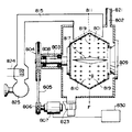
이하 본 발명에 따른 제 3 실시예의 구성을 첨부도면에 의거 설명하면 제 15 도 및 제 16 도는 본 발명의 제 3 실시예를 나타낸 것이다. 도면에서 601은 회전드럼인데, 원통상을 하고 있으며, 회전축(603)을 대략 수평으로 유지하면서 회전자재하게 되어 있어서, 회전축(603)에 고착돼 있는 풀리(604), 구동용밸브(605), 모우터(607)에 고착돼 있는 구동용 풀리(606)의 전달경로로 구동되게 돼 있다. 또 드럼(601)의 외통면(610)에는 통기, 통수용 구멍(619)이 뚫려 있다. 602는 외통으로서 드럼(601)의 외부에 배치돼 있으며, 드럼 회전축(603)을 받치는 브래켓트(bracket) 및 베어링 류로 이뤄지는 드럼 사포오트(support)(608)를 한편에 고착하고, 다른 편에는 드럼(601)에 물, 증기, 가열공기 등을 공급하기 위한 취입부(609A, 609B)가 고착되어 있다. 회전축(603)은 드럼(601)에 고착돼 있고, 드럼 구동축으로서의 책임을 다하는 것이다. 또 풀리(604)는 드럼(601)을 구동 하기위한 풀리이며, 회전축(603)에 고착돼 있다. 모우터(607)는 드럼(601)을 구동하기 위한 동력원이고, 회전수는 속도가변장치(630)에 의해 설정되게 돼있다.Hereinafter, a configuration of a third embodiment according to the present invention will be described with reference to the accompanying drawings. FIGS. 15 and 16 show a third embodiment of the present invention. In the drawing, 601 is a rotating drum, which has a cylindrical shape, and rotates while keeping the
취입부(609A)는 드럼외등(602)의 입구부에 고착돼 있고, 드럼(601) 안으로 물, 증기, 가열공기 등을 들여보내는 것으로, 링의 형상을 하고 있으며, 내주면에 개구부(620)가 있다. 또 드럼(601)의 외부는 공급된 물, 증기, 가열공기 등이 새지 않는 구조로 돼 있다. 또 취입부(609B)는 외동(602)의 측면에 고착돼 있고, 드럼(601)안으로 가열공기를 들려보내는 것이다. 611은 블로워로, 외부공기를 흡입하며 동 외부공기는 히이터(624)를 거쳐 열풍과 열교환하고, 열린 한편, 또는 양편의 댐퍼(614A, 614B)를 통과하고, 드럼외동(602)의 측면에 고착돼 있는 닥트(615A, 615B)를 거쳐 드럼(601)의 외동(602)에 열풍을 들여보낸다.The blowing
상기 블로워(611)은 에어탱크(미도시)에 접속될 수도 있고 실내공기를 직접 끌어 들일 수도 있으며 에어탱크가 복수개일 경우 블로워도 이에 상응하게 각각 복수개로 할 수 있으며 댐퍼도 이에 대응되게 복수개로 구성할 수 있다.The
616은 도어(door)며 리넨을 드럼(601)내에 투입할때는 열리고, 세탁, 탈수, 건조의 고정 동안은 닫혀있다. 또 도아(616)의 내면은 드럼의 오동(602)의 취입부(609A)와 밀착되어 있어 물, 증기, 가열증기 등이 외부로 새지않는 구조로돼 있다. 617은 비이터며, 드럼(601)의 외통면(610)의 내변에 복수개 부착된 축방향으로 뻗은 뫼산(山)자 형의 판이고, 드럼(601)의 회전에 따라 리넨을 위로 들어 올리는 효과를 가지고 있다. 618은 씨일이며, 드럼 외동(602)에 고착돼 드럼(601)의 외통면(610)과 습동하는 구조로 돼 있고, 취입부(609A)로부터 드럼(601)안으로 공급되는 가열증기, 가열공기 등이 드럼(601)에 들어가지 않고 외동(602)에 새는 것을 방지하는 역할을 갖추고 있다.616 is a door that opens when the linen is fed into the
상기 통수용 구멍(619)은, 드럼(601)의 외주면에 뚫린 직경수 mm의 구멍이며, 세탁공정에 있어서는 드럼(601)내와 외동(602)의 세탁수, 세제 등이 이리로 출입한다. 또 탈수공정에 있어서는, 드럼(601)이 고속회전 하는데 따라 리넨에서 털어내어지는 수분이 이 구멍으로부터 외동(602)안에 배출된다. 한편, 건조 공정에 있어서는, 드럼(601)내에 공급된 가열공기는 리넨을 건조시키는 에너지를 드럼(601)내에 공급하고, 그 뒤 이 공기는 상기 구멍(619)으로부터 외동(602)에 배출되어 기외(機外)로 배출된다. 620은 개구로서 취입부(609A)의 내부면에 뚫인구멍이고, 이 구멍으로 드럼(601)안에 가열증기, 가열공기 등이 공급된다. 또한 가열공기는 취입부(609B)로 공급되며, 외동(602)을 거쳐 드럼(601)내로 공급된다. 621은 급수관이며, 세탁공정 도중 또는 탈수공정에 있어서 드럼 외동(602)으로부터 물을 배수할때 사용되며, 댐퍼(623)의 개폐로서 배수의 유무를 제어하는 것이다. 댐퍼(623)는 외동(602)으로부터 배수할때는 열고, 외동(602)내의 세탁수, 탈수에 의해 떨어뜨려진 물을 외동(602)으로부터 배구관(622)을 거쳐 기외의 배수구(溝)(622)로 배출된다. 또한 외동(602)으로부터 배수하지 않을때는 댐퍼(623)는 닫혀있다. 624는 히이터며 드럼(601)내에 가열공기를 공급할때 블로워(611)로써 기외의 공기를 빨아들이고, 동 히이터(624)로써 실내의 공기를 가열해서 드럼(601)안으로 들여보낸다. 또한 동 히이터(624)는 증기 또는 가열 오일과 실내공기를 열교환 시키는 방식이 일반적이다.The
626은 배기구며, 드럼의 외동(602)의 일부에 설치돼 있고 외동(602)내의 공기를 기외로 배출하기 위한 출구다. 또 드럼(601) 밖으로 배기된 공기에는 리넨의 실부스러기(린트-lint)가 대량으로 섞여 있기 때문에, 배기구(626)를 거쳐 배출된 공기를 린트 필터(627)를 통과시킴으로써 배기공기중에 포함돼 있는 린트를 포착할 수 있도록 돼 있다. 628은 배기닥트이며, 린트 필터(627)를 거쳐 린트가 제거된 배기를 기외로 배출하기 위한 것이다. 또 속도 가변장치(630)는, 모우터607)의 회전속도를 조정하는 장치며, 세탁공정, 탈수공정, 건조공정 각각에 있어서 최적의 속도로 드럼(601)이 회전하도록 제어한다. 631은 방진(放振)방치며, 드럼(601) 및 외동(602) 등은 이 방진장치(631) 위에 걸쳐 있다.626 is an exhaust port, which is installed in a part of the
다음에 본 실시예의 작용을 설명하면, 먼저 세탁의 경우에는 급수관(621)으로부터 물을 드럼(601), 외동(602)안으로 일정량 급수한다. 드럼(601)의 외주면에는 구멍(619)이 열려 있기 때문에, 드럼(601)내로 공급되는 물은 그 구멍(619)을 통과해서 외동(602)안에 고인 다음, 차츰 드럼(601)내의 수위가 상승해 가면 도시하지 않는 수위 검지장치로써 수위를 첵크해서, 일정수위가 되면 급수를 정지한다. 다음에 도어(616)를 열고 리넨을 드럼(601)안에 공급한다.Next, the operation of the present embodiment will be described. First, in the case of washing, a predetermined amount of water is supplied from the
다음에 모우터(607)를 구동하고, 일정 회전수로 드럼(601)을 회전시킨다. 또, 드럼(601)의 회전은 정전, 역전을 되풀이하는 것이 리넨에 헝크러져 붙는 것을 막는데 효과적이다. 다음, 도시하지 않는 세제, 조제(助劑)공급장치로부터 세제, 조제를 드럼(601)내에 공급해서 예비빨래를 한다. 예비빨래가 끝난 싯점에서 댐퍼(623)를 열고, 예비빨래에 사용한 세탁수를 배수관(622)을 거쳐 배수구(622)로 배출하고, 일정시간 뒤에, 또는 예비빨래 물의 배출이 끝난 것을 도시하지 않는 센서로 감지하고 나서 댐퍼(623)를 닫는다. 다음에, 마찬가지로 또 세탁수를 드럼(601)안에 일정수위 만큼 급수하고, 또 도시하지 않는 세제, 조제 공급장치로부터 세제, 조제를 드럼(601)안에 공급한다.Next, the
여기서 도시하지 않는 증기노즐을 작용시켜, 외동(602)의 수중에 증기를 불어넣어 세탁수를 일정온도까지 승온시킨다. 드럼(601)의 회전은, 속도가변장치(630)의 제어를 받아 모우터(607)의 회전수를 가변으로 할 수가 있다. 또 세탁물을 비니터(617)로서 드럼(601)의 위쪽까지 들어올려, 낙하할때의 수면과의 충격에 의한 기계력 또는 드럼(601)을 도시하지 않은 가진(加振)장치에 의해 가진 시켜서, 리넨과 세탁수와의 상대속도를 강제적으로 크게 만드는 작용 등으로써 세탁시간을 단축할 수가 있다. 이렇게해서 온수에서 본 빨래를 하고, 그 뒤 드럼(601)의 회전을 중간정도의 속도(中速)의 회전으로 바꿔 리넨에 배어있는 세탁수를 원심력에 의해 털어버린다. 이때엔 당연히 댐퍼(623)를 열어 세탁수를 배수관(622)을 통해 기외로 배출한다.The steam nozzle (not shown) is operated to blow steam into the water of the
그 뒤 댐퍼(623)를 닫고 물을 드럼(601)내에 다시 공급해서 헹굼 공정을 실시한다. 또한 헹굼공정을 세탁공정과 같은 식으로 해도 좋고, 또 세탁수의 급수, 배수를 되풀이 해서 헹굼공정이 끝나면 다음은 탈수공정으로 들어간다.Thereafter, the
다음, 탈수 공정에 대해 설명하면, 드럼(601)은 속도가변장치(630)의 제어에 의해, 드럼 내주에 있어서 1∼1.5G의 가속도를 받는 회전으로 운전된다. 이래서 드럼(601)안에 들어가 있는 리넨은, 드럼(601) 내주면에 대략 균일하게 분포시킬 수가 있다. 이 상태가 된 후, 드럼(601)은 고속회전되고, 리넨에 밴물은 원심력에 의해 드럼(601)의 구멍(619)으로부터 외부에 배출되고, 이 물은 외동(602)으로부터 배수관(622)을 거쳐 기외로 배출된다.Next, the dehydration step will be described. The
또 탈수공정에 들어가기전의 헹굼공정 도중에서부터 헹구는 물에 도시하지 않는 증기노즐로 증기를 공급한다. 이에따라 헹구는 물의 온도가 올라가고, 그 결과로 리넨의 온도도 차차 올라가 100℃ 가까이까지 승온한다. 물의 표면장력은 수온이 오르면 적어지기 때문에 원심탈수에 있어서의 탈수효과를 20% 정도 상승시 시키는 것이 가능하다.In addition, steam is supplied to the water to be rinsed from the middle of the rinsing step before entering the dehydration step to a steam nozzle not shown. As a result, the temperature of the water to be rinsed rises, and as a result, the temperature of the linen gradually rises to about 100 ° C. Since the surface tension of water decreases as the water temperature rises, it is possible to increase the dehydration effect in centrifugal dehydration by about 20%.
다음에 건조에 대해 설명하면, 탈수공정의 종료가 가까워 지면서 댐퍼 614A를 열고 614B를 닫으면서 히이터(624)에서 가열된 공기를 탁트(615A), 취입부(609A)를 경유해서 드럼(601)안으로 공급한다(제 18 도). 일정시간 후, 이번에는 댐퍼 614A를 닫고 614B를 열면서 닥트(615B), 취입부(609B)를 경유해서 (제 19 도), 드럼(601)안으로 공급한다. 이에 따라 드럼(601)안에 세탁물(612)은 드럼 중앙부, 외주부가 공히 승온된다.Next, the drying will be described. As the end of the dehydration process approaches, the air heated in the
탈수공정이 종료하면, 그대로 건조공정으로 이행한다. 세탁물(612)의 부하량을, 세탁탈수기로 하여 계산해서 드럼(601)안에 공급하고, 이 상태에서 건조공정으로 이행하면, 건조기로서의 부하량으로서는 통상의 약 2배가 된다. 세탁물(612)은 자신의 부피가 커지는 숭고성(嵩高性)에 의해, 제 18 도, 제 19 도에 표시하는 바와 같이 드럼(601)에 대략 가득차게 되고 세탁물(612)끼리는 자중으로서는 자유로이 움직일 수 없는 상태가 된다.After the dehydration step is completed, the process proceeds directly to the drying step. When the load of the
여기서 드럼(601)의 회전수를, 중력 가속도 G로 표시해 설명한다.Here, the rotation speed of the
G=R/9.8×(2πn/60)2 G = R / 9.8 × (2πn / 60) 2
R=드럼 반경(m)R = drum radius (m)
n=드럼의 회전수(rpm)n = speed of drum (rpm)
또한 회전수를 1G 미만으로 하고, 소망스럽게는 0.7∼0.8G로 한다.Moreover, the rotation speed shall be less than 1 G and hopefully 0.7-0.8 G.
본 발명은 드럼(601)안에 건조기로서의 통상의 부하량(일본산업기계공업화 표준부하량 등)보다도 지나치게 큰 부하를 가했을 때에도 세탁물(612)을 균일하게, 단시간에 건조시키는 것을 목적으로 하는 것이다.An object of the present invention is to dry the
즉, 먼저 제 18 도에 나타내듯이 가열공기를, 댐퍼 614A를「엶」(開), 614B를「닫음」(閉)으로 해서 닥트(615A)에 인도하고, 취입부(609A)로부터 드럼(601)안에 공급한다. 드럼(601)안의 세탁물은 가열공기의 압력에 의해, 드럼(601)의 외통면(610)측에 약간 밀어 붙여진 상태로, 드럼(601)과 함께 회전한다. 가열공기는 드럼 외통(602)의 배기구(口)(626)로부터 기외로 배출된다. 이 상태대로 건조를 계속하면 드럼(601)의 중앙부의 수분부착량과 외통면(610)측의 수분부착량은 제 20 도처럼 되며, 외통면(610)측은 10% 가까이 높은 값이 된다. 여기서의 값은 건조개시 10분후의 값이며, 수분부착량의 평균치는 제 17 도에 표시하는 종래 방식(2)에 표시하는 건조곡선에 표시하듯이 시간의 경과와 더불어 작아지고, 건조가 종료한다.That is, first, as shown in FIG. 18, the heated air is led to the
또 제 19 도에 표시하듯이, 가열공기를 댐퍼 614A를 「엶」으로 하고, 614B를 「닫음」으로 해서 닥트(615B)에 인도해서, 취입부(609B)로부터 드럼(601)안에 공급하면, 드럼(601)안의 세탁물(612)은, 가열공기의 압력에 의해 약간 드럼안으로 밀어붙여진 상태가 된다. 이 상태에서의 건조를 계속하면 외통면의 세탁물은 드럼(601)의 중앙부에 비해 수분부착량은 적어진다. 드럼 외통면과 드럼 중앙부의 수분부착량은, 제 21 도에 나타낸 분포가 되며, 중앙부는 10% 가까이 높은 값이 된다. 수분부착량의 평균치는, 제 17 도의 종래방식(1)에 표시하는 건조곡선 처럼 시간의 경과와 더불어 작아진다.In addition, as shown in FIG. 19, when the heated air is supplied to the duct 615B with the
본 발명에서는, 상술한 바와 같이 제 18 도, 제 19 도에 표시하는 가열공시의 취입을 번갈아 절환함으로써, 건조의 균일화와 건조시간의 단축을 실현할 수가 있다. 이 실측치는 다음과 같다.In the present invention, as described above, by alternately switching the blow-ups shown in FIGS. 18 and 19, the uniformity of drying and the shortening of drying time can be realized. This measured value is as follows.
드럼형상 : 지름 ; 1.3m, 깊이 ; 0.6mDrum shape: diameter; 1.3 m, depth; 0.6m
블로워 용량 : 50m3/minBlower capacity: 50m 3 / min
가열공기의 절환주기 : 3분Switching cycle of heated air: 3 minutes
[건조소요시간][Drying time]

단, 상기한 시간은 수분 부착량 60%의 타월을, 수분부착량 4%로 건조시키기까지의 시간이다.However, said time is time to dry the towel | cover of 60% of water adhesion amount to 4% of water adhesion amount.
또한, 일본산업기계공업회 표준부하량에 의하면, 상기 드럼은,In addition, according to the standard load of the Japan Industrial Machinery Industry Association, the drum,
세탁탈수기로서 67kg67 kg as a laundry dehydrator
건조기로서 32kg32 kg as a dryer
이다. 건조기로서의 표준부하량 32kg인데다가, 60kg의 부하량을 공급해도, 30kg 부하의 경우의 건조시간 10분에 대해 그 1.5배인 15분으로 건조가 가능해졌다. 또 드럼내의 세탁물은, 균일하게 건조시킬 수가 있었다. 상기는 건조시간 단축을 위해 블로워 용량을 일반의 값보다 크게 한 것을 말해둔다.to be. Even if a load of 60 kg was supplied with a standard load of 32 kg as a dryer, it was possible to dry in 15 minutes, which is 1.5 times that of 10 minutes of drying time in the case of a 30 kg load. In addition, the laundry in the drum could be dried uniformly. The above is to say that the blower capacity is larger than the normal value in order to shorten the drying time.
또한 본 발명에 따른 상기 제 3 실시예에서는 회전드럼(601)에의 가열공기의 공급을 제 18 도, 제 19 도에 보이는 2개의 방식을 일정시간 동안 동시에 실시해도, 드럼(601)내의 세탁물(612)의 균일건조, 단시간화에 효과를 발할 수가 있다. 또 이상은 물빨래의 경우를 설명한 것이지만, 퍼크롤에틸렌 등 유기용제를 사용하는 드라이클리이닝 기계에도 적용가능하다. 또한 세탁, 탈수, 건조의 각 공정을 연속해서 1대의 기계로 처리하는 상기 실시예 이외에, 건조기로서만 기능하는 드럼식 건조시에도 적용할 수 있다.Further, in the third embodiment according to the present invention, even if the two air systems shown in FIGS. 18 and 19 are simultaneously supplied for a certain time, the
상기 제 3 실시예는 이상 상세히 설명한 바와 같이 구성되 있기 때문에 건조기로서의 표준부하량 이상의 세탁물을 드럼 안에 공급했을때, 드럼의 축방향 및 외통 방향으로부터 번갈아 또는 동시에 가열공기를 취입함으로써 세탁물 각각을 균일하게 건조시킬 수가 있는 동시에 건조시간을 단축할 수가 있어 작은 드럼용량으로서 열효율이 양호한 건조를 실현할 수가 있다.Since the third embodiment is configured as described in detail above, when laundry is supplied into the drum with a load of the standard load or more as a dryer, the laundry is dried uniformly by injecting heating air alternately from the axial and outer cylinder directions of the drum or simultaneously. In addition, the drying time can be shortened, and drying with good thermal efficiency can be realized with a small drum capacity.
상기에 있어서 본 발명에 따른 제 1 실시예는 드럼 외주면의 산형각도에 관한 것으로서, 제 2 실시예는 드럼내 도입되는 열풍의 성격, 즉 흡인식 정류열풍으로부터 취입식 분류열풍으로 바꾼 것에 관한 것으로서, 그리고 제 3 실시예는 드럼내 취입되는 열풍의 도입방향이 그 측벽과 중앙부에 동시 또는 교대로 이루어지는 것에 관한 것으로서 각각 그 기본적인 목적과 구성을 가지고 있지만 이들 세실시예는 각각 적절히 조합됨으로써 단일 구조에 의해 상기 세가지 실시예의 목적, 효과를 모두 달성할 수도 있다. 즉 이러한 조합예 중의 하나는 제 22 도 및 제 23 도로 도시한 바와 같은 것을 들 수 있으며 그 구성 및 작동은 전술한 실시예와 대응되는 도면부호를 참조하여 용이하게 이해할 수 있을 것이다.In the above, the first embodiment according to the present invention relates to the angular angle of the drum outer circumferential surface, and the second embodiment relates to the nature of the hot air introduced into the drum, that is, from the suction type rectification hot air to the blown type hot air. The third embodiment relates to the introduction direction of the hot air blown into the drum at the same time or alternately in the side wall and the central part, each having its basic purpose and configuration. The objects and effects of the three embodiments may be achieved. That is, one of the combination examples may be as shown in FIGS. 22 and 23 and the configuration and operation will be easily understood with reference to the reference numerals corresponding to the above-described embodiments.
Claims (2)
Priority Applications (3)
| Application Number | Priority Date | Filing Date | Title |
|---|---|---|---|
| KR1019920001311A KR920009545B1 (en) | 1988-09-13 | 1992-01-29 | Drum type laundry management apparatus |
| KR1019920001312A KR920007733B1 (en) | 1988-10-26 | 1992-01-29 | Drum type laundry-management apparatus |
| KR1019920001313A KR920009546B1 (en) | 1988-12-06 | 1992-01-29 | Method of laundry discharge |
Applications Claiming Priority (14)
| Application Number | Priority Date | Filing Date | Title |
|---|---|---|---|
| JP63040513A JP2671925B2 (en) | 1988-02-23 | 1988-02-23 | Washing, draining and drying washing machines for linen laundry |
| JP63-40513 | 1988-02-23 | ||
| JP63-61281 | 1988-03-15 | ||
| JP63061281A JPH01236096A (en) | 1988-03-15 | 1988-03-15 | Drum dryer |
| JP63-188661 | 1988-07-28 | ||
| JP63188661A JPH084670B2 (en) | 1988-07-28 | 1988-07-28 | Drum type laundry processing device |
| JP63227418A JPH0277292A (en) | 1988-09-13 | 1988-09-13 | Drum system laundry processor |
| JP63-227418 | 1988-09-13 | ||
| JP63-139766(?) | 1988-10-26 | ||
| JP1988139766U JPH0259785U (en) | 1988-10-26 | 1988-10-26 | |
| JP63306942A JP2695650B2 (en) | 1988-12-06 | 1988-12-06 | How to discharge laundry |
| JP63-306942 | 1988-12-06 | ||
| JP1-15580 | 1989-01-25 | ||
| JP1015580A JP2680658B2 (en) | 1989-01-25 | 1989-01-25 | Drum type laundry processing device |
Publications (2)
| Publication Number | Publication Date |
|---|---|
| KR890013266A KR890013266A (en) | 1989-09-22 |
| KR920004722B1 true KR920004722B1 (en) | 1992-06-15 |
Family
ID=27563720
Family Applications (1)
| Application Number | Title | Priority Date | Filing Date |
|---|---|---|---|
| KR1019890002113A KR920004722B1 (en) | 1988-02-23 | 1989-02-22 | Drum type washing apparatus and method of processing the wash using said apparatus |
Country Status (4)
| Country | Link |
|---|---|
| US (2) | US5050259A (en) |
| EP (4) | EP0548064B1 (en) |
| KR (1) | KR920004722B1 (en) |
| DE (4) | DE68928139T2 (en) |
Families Citing this family (87)
| Publication number | Priority date | Publication date | Assignee | Title |
|---|---|---|---|---|
| US5289703A (en) * | 1989-06-16 | 1994-03-01 | Mitsubishi Jukogyo Kabushiki Kaisha | Drum type washing machine |
| JP2738957B2 (en) * | 1989-06-16 | 1998-04-08 | 三菱重工業株式会社 | Drum type washing machine |
| FR2678960B1 (en) * | 1991-07-10 | 1993-10-29 | Ardam | PROCESS AND DEVICE FOR REMOVING BUTTER DEPOSITS IN THE HOT AIR PRODUCTION CIRCUIT OF WASHING AND DRYING MACHINES. |
| US5887456A (en) * | 1995-08-30 | 1999-03-30 | Sharp Kabushiki Kaisha | Drum type drying/washing machine |
| JP3299429B2 (en) * | 1995-12-13 | 2002-07-08 | 松下電器産業株式会社 | Battery electrode drying equipment |
| DE19625707A1 (en) * | 1996-06-27 | 1998-01-08 | Gerhard Engel | Method and device for unloading laundry items from a processing machine |
| US6045588A (en) | 1997-04-29 | 2000-04-04 | Whirlpool Corporation | Non-aqueous washing apparatus and method |
| US7534304B2 (en) | 1997-04-29 | 2009-05-19 | Whirlpool Corporation | Non-aqueous washing machine and methods |
| US5940988A (en) * | 1998-02-23 | 1999-08-24 | Eisen; Daniel | Apparatus and method for dry cleaning |
| US6272770B1 (en) * | 1999-12-15 | 2001-08-14 | American Dryer Corporation | Washer/dryer combination with cold water and vacuum |
| US7513132B2 (en) | 2003-10-31 | 2009-04-07 | Whirlpool Corporation | Non-aqueous washing machine with modular construction |
| ATE366837T1 (en) * | 2002-05-17 | 2007-08-15 | Howa Kabushiki Kaisha | TEXTILE DYEING DEVICE AND METHOD |
| KR100451742B1 (en) * | 2002-08-13 | 2004-10-08 | 엘지전자 주식회사 | ventilation type clothes dryer |
| JP3812517B2 (en) * | 2002-08-30 | 2006-08-23 | 松下電器産業株式会社 | Drum washing machine |
| DE10323494A1 (en) * | 2003-05-23 | 2004-12-30 | BSH Bosch und Siemens Hausgeräte GmbH | clothes dryer |
| US7627960B2 (en) * | 2003-06-30 | 2009-12-08 | General Electric Company | Clothes dryer drum projections |
| US7695524B2 (en) | 2003-10-31 | 2010-04-13 | Whirlpool Corporation | Non-aqueous washing machine and methods |
| US7300468B2 (en) | 2003-10-31 | 2007-11-27 | Whirlpool Patents Company | Multifunctioning method utilizing a two phase non-aqueous extraction process |
| US7739891B2 (en) | 2003-10-31 | 2010-06-22 | Whirlpool Corporation | Fabric laundering apparatus adapted for using a select rinse fluid |
| US7513004B2 (en) | 2003-10-31 | 2009-04-07 | Whirlpool Corporation | Method for fluid recovery in a semi-aqueous wash process |
| US7462203B2 (en) * | 2003-12-23 | 2008-12-09 | Whirlpool Corporation | Method of disposing waste from in-home dry cleaning machine using disposable, containment system |
| US20050278983A1 (en) * | 2004-03-01 | 2005-12-22 | Maytag Corporation | Filter vent for drying cabinet |
| JP4271064B2 (en) * | 2004-03-10 | 2009-06-03 | 三洋電機株式会社 | Drum washing machine |
| US20050224099A1 (en) * | 2004-04-13 | 2005-10-13 | Luckman Joel A | Method and apparatus for cleaning objects in an automatic cleaning appliance using an oxidizing agent |
| US7837741B2 (en) | 2004-04-29 | 2010-11-23 | Whirlpool Corporation | Dry cleaning method |
| KR101093878B1 (en) * | 2004-06-05 | 2011-12-13 | 엘지전자 주식회사 | A drum apparatus of a dryer |
| US8122547B2 (en) * | 2004-07-20 | 2012-02-28 | Lg Electronics Inc. | Washing machine and method for controlling the same |
| DE102004055942A1 (en) * | 2004-11-19 | 2006-05-24 | BSH Bosch und Siemens Hausgeräte GmbH | clothes dryer |
| KR100662369B1 (en) * | 2004-11-30 | 2007-01-02 | 엘지전자 주식회사 | complex type dryer having a clothes hanger for supplying heat air |
| CN100560847C (en) * | 2004-12-06 | 2009-11-18 | Lg电子株式会社 | Dryer |
| EP1863970B1 (en) * | 2005-03-31 | 2014-12-31 | LG Electronics Inc. | Laundry dryer |
| US7966684B2 (en) | 2005-05-23 | 2011-06-28 | Whirlpool Corporation | Methods and apparatus to accelerate the drying of aqueous working fluids |
| US8015726B2 (en) * | 2005-06-23 | 2011-09-13 | Whirlpool Corporation | Automatic clothes dryer |
| JP3919798B2 (en) * | 2005-06-28 | 2007-05-30 | シャープ株式会社 | Washing and drying machine |
| WO2007013327A1 (en) * | 2005-07-28 | 2007-02-01 | Sharp Kabushiki Kaisha | Drum type drying and washing machine |
| EP1932962B1 (en) * | 2005-10-07 | 2012-10-24 | Sanyo Electric Co., Ltd. | Clothes drier |
| US7958650B2 (en) * | 2006-01-23 | 2011-06-14 | Turatti S.R.L. | Apparatus for drying foodstuffs |
| DE102007007354B4 (en) | 2006-02-20 | 2013-10-10 | Lg Electronics Inc. | Clothes dryer and method of control |
| EP1852541B1 (en) * | 2006-05-02 | 2011-08-10 | Electrolux Home Products Corporation N.V. | Dryer with drying sequence using an additive |
| EP2055820B1 (en) * | 2006-05-02 | 2013-04-10 | Electrolux Home Products Corporation N.V. | Steam supplying method and treatment apparatus |
| BRPI0712435A2 (en) * | 2006-06-01 | 2012-06-26 | Electrolux Home Prod Corp | steam supply method and treatment apparatus |
| WO2007137857A1 (en) * | 2006-06-01 | 2007-12-06 | Electrolux Home Products Corporation N.V. | Steam supplying method and treatment apparatus |
| US7627920B2 (en) * | 2006-06-09 | 2009-12-08 | Whirlpool Corporation | Method of operating a washing machine using steam |
| US7765628B2 (en) * | 2006-06-09 | 2010-08-03 | Whirlpool Corporation | Steam washing machine operation method having a dual speed spin pre-wash |
| US7730568B2 (en) * | 2006-06-09 | 2010-06-08 | Whirlpool Corporation | Removal of scale and sludge in a steam generator of a fabric treatment appliance |
| US20070283509A1 (en) * | 2006-06-09 | 2007-12-13 | Nyik Siong Wong | Draining liquid from a steam generator of a fabric treatment appliance |
| US7941885B2 (en) * | 2006-06-09 | 2011-05-17 | Whirlpool Corporation | Steam washing machine operation method having dry spin pre-wash |
| US20070283728A1 (en) * | 2006-06-09 | 2007-12-13 | Nyik Siong Wong | Prevention of scale and sludge in a steam generator of a fabric treatment appliance |
| KR100830514B1 (en) | 2006-06-12 | 2008-05-21 | 엘지전자 주식회사 | laundry dryer and method for controlling the same |
| JP4022239B1 (en) * | 2006-08-10 | 2007-12-12 | シャープ株式会社 | Washing dryer and control method thereof |
| US20080041120A1 (en) * | 2006-08-15 | 2008-02-21 | Nyik Siong Wong | Fabric Treatment Appliance with Anti-Siphoning |
| US7707859B2 (en) * | 2006-08-15 | 2010-05-04 | Whirlpool Corporation | Water supply control for a steam generator of a fabric treatment appliance |
| US7886392B2 (en) * | 2006-08-15 | 2011-02-15 | Whirlpool Corporation | Method of sanitizing a fabric load with steam in a fabric treatment appliance |
| US7591859B2 (en) * | 2006-08-15 | 2009-09-22 | Whirlpool Corporation | Water supply control for a steam generator of a fabric treatment appliance using a weight sensor |
| US7841219B2 (en) * | 2006-08-15 | 2010-11-30 | Whirlpool Corporation | Fabric treating appliance utilizing steam |
| US7681418B2 (en) * | 2006-08-15 | 2010-03-23 | Whirlpool Corporation | Water supply control for a steam generator of a fabric treatment appliance using a temperature sensor |
| US7665332B2 (en) * | 2006-08-15 | 2010-02-23 | Whirlpool Corporation | Steam fabric treatment appliance with exhaust |
| US20080040869A1 (en) * | 2006-08-15 | 2008-02-21 | Nyik Siong Wong | Determining Fabric Temperature in a Fabric Treating Appliance |
| KR101305287B1 (en) * | 2006-10-02 | 2013-09-06 | 엘지전자 주식회사 | Washing machine with odor removal function |
| US20080092928A1 (en) * | 2006-10-19 | 2008-04-24 | Whirlpool Corporation | Method and Apparatus for Treating Biofilm in an Appliance |
| US7753009B2 (en) | 2006-10-19 | 2010-07-13 | Whirlpool Corporation | Washer with bio prevention cycle |
| US20080095660A1 (en) * | 2006-10-19 | 2008-04-24 | Nyik Siong Wong | Method for treating biofilm in an appliance |
| US7997006B2 (en) * | 2007-01-12 | 2011-08-16 | Lg Electronics Inc. | Laundry machine and control method thereof |
| US7458171B1 (en) * | 2007-01-29 | 2008-12-02 | Lentz Luke E | Dehumidifier clothes dryer apparatus |
| KR100776263B1 (en) * | 2007-02-12 | 2007-11-15 | 삼성전자주식회사 | Drum type washing machine |
| DE102007016074A1 (en) * | 2007-04-03 | 2008-10-09 | BSH Bosch und Siemens Hausgeräte GmbH | Method and device for cleaning a component, in particular an evaporator of a condenser device, and laundry or tumble dryer with such a device |
| KR101356496B1 (en) * | 2007-04-25 | 2014-01-29 | 엘지전자 주식회사 | Washer |
| US8393183B2 (en) | 2007-05-07 | 2013-03-12 | Whirlpool Corporation | Fabric treatment appliance control panel and associated steam operations |
| US7905119B2 (en) * | 2007-08-31 | 2011-03-15 | Whirlpool Corporation | Fabric treatment appliance with steam generator having a variable thermal output |
| US8555676B2 (en) * | 2007-08-31 | 2013-10-15 | Whirlpool Corporation | Fabric treatment appliance with steam backflow device |
| US7966683B2 (en) * | 2007-08-31 | 2011-06-28 | Whirlpool Corporation | Method for operating a steam generator in a fabric treatment appliance |
| US8555675B2 (en) * | 2007-08-31 | 2013-10-15 | Whirlpool Corporation | Fabric treatment appliance with steam backflow device |
| US7690062B2 (en) | 2007-08-31 | 2010-04-06 | Whirlpool Corporation | Method for cleaning a steam generator |
| US8037565B2 (en) * | 2007-08-31 | 2011-10-18 | Whirlpool Corporation | Method for detecting abnormality in a fabric treatment appliance having a steam generator |
| US7918109B2 (en) * | 2007-08-31 | 2011-04-05 | Whirlpool Corporation | Fabric Treatment appliance with steam generator having a variable thermal output |
| US7861343B2 (en) | 2007-08-31 | 2011-01-04 | Whirlpool Corporation | Method for operating a steam generator in a fabric treatment appliance |
| DE102007049061A1 (en) * | 2007-10-12 | 2009-04-16 | BSH Bosch und Siemens Hausgeräte GmbH | Method and device for cleaning a component, in particular an evaporator of a condenser device, and laundry or tumble dryer with such a device |
| DE102007049959A1 (en) * | 2007-10-18 | 2009-04-23 | BSH Bosch und Siemens Hausgeräte GmbH | Lint filter device and household appliance with such a lint filter device |
| KR101256145B1 (en) * | 2007-11-05 | 2013-04-23 | 동부대우전자 주식회사 | Dryer having indrawn tube with heater |
| KR101308510B1 (en) * | 2007-11-05 | 2013-09-12 | 동부대우전자 주식회사 | Dryer having indrawn tube with heater |
| CN101498089B (en) * | 2008-01-31 | 2010-12-01 | 博西华电器(江苏)有限公司 | Method for processing clothing and electrical equipment therefor |
| DE102008032800A1 (en) | 2008-07-11 | 2010-01-14 | BSH Bosch und Siemens Hausgeräte GmbH | Device for cleaning a component, in particular an evaporator of a capacitor device |
| KR101525569B1 (en) * | 2008-12-22 | 2015-06-03 | 엘지전자 주식회사 | Fabric treating apparatus |
| DE102009001548A1 (en) * | 2009-03-13 | 2010-09-16 | BSH Bosch und Siemens Hausgeräte GmbH | A laundry drying apparatus having a lint filter disposed within a process air cycle and method of operating the laundry dryer |
| US8275516B2 (en) * | 2009-07-21 | 2012-09-25 | Trimble Navigation Limited | Agricultural vehicle autopilot rollover risk assessment system |
| US20110023554A1 (en) * | 2009-07-31 | 2011-02-03 | Bsh Home Appliances Corporation | Damping system for a household appliance |
| CN109827388B (en) * | 2019-01-28 | 2021-02-02 | 江苏华艺服饰有限公司 | Fabric dewatering device |
Family Cites Families (32)
| Publication number | Priority date | Publication date | Assignee | Title |
|---|---|---|---|---|
| DE54165C (en) * | H. ANDREE in Nauen | Innovation in centrifuges for sugar filling mass and the like | ||
| US965813A (en) * | 1908-11-27 | 1910-07-26 | Hubert M Greist | Tumbling-barrel. |
| US1060801A (en) * | 1910-12-17 | 1913-05-06 | Frank M Watkins | Laundry-drier. |
| US1247798A (en) * | 1916-06-07 | 1917-11-27 | William Dohn | Clothes-drying tumbler-machine. |
| US1301055A (en) * | 1917-10-08 | 1919-04-15 | Alonzo Humberger | Washing-machine. |
| GB183815A (en) * | 1921-07-28 | 1923-04-12 | Guy Courtney | Improvements in machines for washing and partially dehydrating clothes and similar articles |
| US1468588A (en) * | 1922-10-28 | 1923-09-18 | Wilson Frank | Washing machine |
| US1641780A (en) * | 1925-09-22 | 1927-09-06 | Karl Tritscheller | Extractor |
| US1847159A (en) * | 1928-10-25 | 1932-03-01 | Troy Laundry Machinery Co | Extractor |
| GB467594A (en) * | 1935-12-20 | 1937-06-21 | Stanley Newbery | Improvements in and relating to laundry plant and the like |
| US2213453A (en) * | 1938-12-05 | 1940-09-03 | Cincinnati Butchers Supply Co | Washer |
| US2406494A (en) * | 1943-05-14 | 1946-08-27 | Gen Motors Corp | Domestic appliance |
| US2500861A (en) * | 1945-06-30 | 1950-03-14 | Udylite Corp | Machine for treating articles in bulk |
| US2580435A (en) * | 1947-01-29 | 1952-01-01 | Apex Electrical Mfg Co | Washing machine |
| DE829159C (en) * | 1950-08-22 | 1952-01-24 | Siemens Schuckertwerke A G | Washing machine |
| DE890037C (en) * | 1950-09-02 | 1953-09-17 | Siemens Ag | Washer-dryer and spin-dryer |
| FR1113123A (en) * | 1954-09-24 | 1956-03-23 | Washing machine | |
| FR1193955A (en) * | 1957-04-08 | 1959-11-05 | ||
| AT220578B (en) * | 1960-05-17 | 1962-04-10 | Karl Ing Wuck | Centrifuge provided with a pump, in particular laundry centrifuge |
| FR1370320A (en) * | 1963-09-24 | 1964-08-21 | Siemens Elektrogeraete Gmbh | Washing machine |
| US3358301A (en) * | 1963-10-22 | 1967-12-19 | Whirlpool Co | Laundry machine and method |
| BE677929A (en) * | 1965-03-25 | 1966-09-01 | ||
| US3387385A (en) * | 1965-10-22 | 1968-06-11 | Whirlpool Co | Nozzle for liquid extraction apparatus |
| US3444710A (en) * | 1967-03-09 | 1969-05-20 | Gen Motors Corp | Domestic clothes washer with fluid flow agitation |
| US3524263A (en) * | 1968-04-03 | 1970-08-18 | Whirlpool Co | Control circuit for a laundry appliance |
| US3546903A (en) * | 1968-10-07 | 1970-12-15 | Braun Inc G A | Cake breaker for laundry apparatus |
| DE2513660A1 (en) * | 1974-04-03 | 1975-10-23 | Arnfried Meyer | DRUM MACHINE FOR THE HANDLING OF UNIVERSAL GOODS |
| DE2704020A1 (en) * | 1977-02-01 | 1978-08-03 | Seco Maschinenbau Gmbh & Co Kg | METHOD AND DEVICE FOR CHEMICAL CLEANING |
| JPS5519266U (en) | 1978-07-24 | 1980-02-06 | ||
| US4285219A (en) * | 1979-01-12 | 1981-08-25 | Engelhardt & Foster | Apparatus for treatment of laundry |
| AU557711B2 (en) * | 1981-03-27 | 1987-01-08 | Fisher & Paykel Limited | Actuating clothes washing machines |
| JPS6351899A (en) * | 1986-08-22 | 1988-03-04 | 三菱重工業株式会社 | Centrifugal liquid remover |
-
1989
- 1989-02-21 EP EP93250071A patent/EP0548064B1/en not_active Expired - Lifetime
- 1989-02-21 DE DE68928139T patent/DE68928139T2/en not_active Expired - Fee Related
- 1989-02-21 DE DE68929057T patent/DE68929057T2/en not_active Expired - Fee Related
- 1989-02-21 EP EP89730040A patent/EP0343096B1/en not_active Expired - Lifetime
- 1989-02-21 EP EP93250068A patent/EP0548063B1/en not_active Expired - Lifetime
- 1989-02-21 DE DE68929146T patent/DE68929146T2/en not_active Expired - Fee Related
- 1989-02-21 EP EP93250070A patent/EP0550423B1/en not_active Expired - Lifetime
- 1989-02-21 DE DE68928640T patent/DE68928640T2/en not_active Expired - Fee Related
- 1989-02-22 KR KR1019890002113A patent/KR920004722B1/en not_active IP Right Cessation
-
1990
- 1990-10-11 US US07/596,741 patent/US5050259A/en not_active Expired - Lifetime
-
1991
- 1991-05-10 US US07/701,364 patent/US5107606A/en not_active Expired - Lifetime
Also Published As
| Publication number | Publication date |
|---|---|
| EP0550423B1 (en) | 2000-01-26 |
| DE68929146T2 (en) | 2000-07-06 |
| EP0343096A3 (en) | 1990-04-18 |
| US5050259A (en) | 1991-09-24 |
| EP0548064A2 (en) | 1993-06-23 |
| EP0548064A3 (en) | 1993-12-15 |
| DE68928640T2 (en) | 1999-03-11 |
| DE68929057D1 (en) | 1999-09-23 |
| EP0548063A3 (en) | 1993-12-15 |
| EP0548063B1 (en) | 1997-06-18 |
| EP0343096B1 (en) | 1999-08-18 |
| EP0550423A3 (en) | 1994-01-12 |
| DE68929146D1 (en) | 2000-03-02 |
| DE68928139D1 (en) | 1997-07-24 |
| EP0343096A2 (en) | 1989-11-23 |
| US5107606A (en) | 1992-04-28 |
| EP0550423A2 (en) | 1993-07-07 |
| EP0548064B1 (en) | 1998-04-08 |
| DE68928640D1 (en) | 1998-05-14 |
| EP0548063A2 (en) | 1993-06-23 |
| DE68928139T2 (en) | 1997-12-04 |
| DE68929057T2 (en) | 2000-02-03 |
| KR890013266A (en) | 1989-09-22 |
Similar Documents
| Publication | Publication Date | Title |
|---|---|---|
| KR920004722B1 (en) | Drum type washing apparatus and method of processing the wash using said apparatus | |
| US5212969A (en) | Drum type washing apparatus and method of processing the wash using said apparatus | |
| EP2290154B1 (en) | Drum type washing and drying machine | |
| CN103282572A (en) | Washing and drying machine | |
| JP2012000313A (en) | Washing/drying machine | |
| JPH11114286A (en) | Drum type washing and drying machine | |
| JPH10235087A (en) | Drier | |
| JPS62221392A (en) | Washing apparatus | |
| EP0403042B1 (en) | Drum type washing machine | |
| JP2660362B2 (en) | Drum type washer / dryer | |
| JPH08215471A (en) | Drum type washing/spin-drying machine | |
| JP2680658B2 (en) | Drum type laundry processing device | |
| JP2671925B2 (en) | Washing, draining and drying washing machines for linen laundry | |
| JPH09173697A (en) | Drum type washing and drying machine | |
| JPS6357099A (en) | Drum type drier | |
| JP2510335Y2 (en) | Washing and drying machine | |
| JP3815144B2 (en) | Washing and drying machine | |
| JPS5812686A (en) | Dehumidifying apparatus of drum type full automatic washer dryer | |
| JPH11347297A (en) | Drum type washing/drying machine | |
| JPH11169580A (en) | Drum type washing/drying machine | |
| JP2010017526A (en) | Washing and drying machine | |
| JPH084670B2 (en) | Drum type laundry processing device | |
| JPH0438993A (en) | Drum type washing-drying machine | |
| KR200275493Y1 (en) | A washing machine | |
| CN115538098A (en) | Washing machine capable of accelerating temperature rise speed of clothes drying and control method thereof |
Legal Events
| Date | Code | Title | Description |
|---|---|---|---|
| A201 | Request for examination | ||
| E902 | Notification of reason for refusal | ||
| G160 | Decision to publish patent application | ||
| E701 | Decision to grant or registration of patent right | ||
| GRNT | Written decision to grant | ||
| FPAY | Annual fee payment |
Payment date: 20010605 Year of fee payment: 10 |
|
| LAPS | Lapse due to unpaid annual fee |