KR900004594B1 - Drop collector for an apparatus for conveying electrodes - Google Patents
Drop collector for an apparatus for conveying electrodes Download PDFInfo
- Publication number
- KR900004594B1 KR900004594B1 KR1019840000459A KR840000459A KR900004594B1 KR 900004594 B1 KR900004594 B1 KR 900004594B1 KR 1019840000459 A KR1019840000459 A KR 1019840000459A KR 840000459 A KR840000459 A KR 840000459A KR 900004594 B1 KR900004594 B1 KR 900004594B1
- Authority
- KR
- South Korea
- Prior art keywords
- trough
- series
- chain
- drop collector
- collector according
- Prior art date
Links
- 239000003792 electrolyte Substances 0.000 claims description 14
- 238000004140 cleaning Methods 0.000 claims description 3
- 239000000725 suspension Substances 0.000 abstract description 2
- 241001417527 Pempheridae Species 0.000 description 2
- 230000004048 modification Effects 0.000 description 2
- 238000012986 modification Methods 0.000 description 2
- 239000000969 carrier Substances 0.000 description 1
- 230000021615 conjugation Effects 0.000 description 1
- 238000005868 electrolysis reaction Methods 0.000 description 1
- 239000008151 electrolyte solution Substances 0.000 description 1
- 239000007788 liquid Substances 0.000 description 1
- 239000002184 metal Substances 0.000 description 1
- 230000000630 rising effect Effects 0.000 description 1
Images


Classifications
-
- C—CHEMISTRY; METALLURGY
- C25—ELECTROLYTIC OR ELECTROPHORETIC PROCESSES; APPARATUS THEREFOR
- C25C—PROCESSES FOR THE ELECTROLYTIC PRODUCTION, RECOVERY OR REFINING OF METALS; APPARATUS THEREFOR
- C25C7/00—Constructional parts, or assemblies thereof, of cells; Servicing or operating of cells
- C25C7/06—Operating or servicing
-
- C—CHEMISTRY; METALLURGY
- C25—ELECTROLYTIC OR ELECTROPHORETIC PROCESSES; APPARATUS THEREFOR
- C25C—PROCESSES FOR THE ELECTROLYTIC PRODUCTION, RECOVERY OR REFINING OF METALS; APPARATUS THEREFOR
- C25C7/00—Constructional parts, or assemblies thereof, of cells; Servicing or operating of cells
-
- B—PERFORMING OPERATIONS; TRANSPORTING
- B08—CLEANING
- B08B—CLEANING IN GENERAL; PREVENTION OF FOULING IN GENERAL
- B08B3/00—Cleaning by methods involving the use or presence of liquid or steam
- B08B3/04—Cleaning involving contact with liquid
-
- B—PERFORMING OPERATIONS; TRANSPORTING
- B65—CONVEYING; PACKING; STORING; HANDLING THIN OR FILAMENTARY MATERIAL
- B65G—TRANSPORT OR STORAGE DEVICES, e.g. CONVEYORS FOR LOADING OR TIPPING, SHOP CONVEYOR SYSTEMS OR PNEUMATIC TUBE CONVEYORS
- B65G49/00—Conveying systems characterised by their application for specified purposes not otherwise provided for
- B65G49/02—Conveying systems characterised by their application for specified purposes not otherwise provided for for conveying workpieces through baths of liquid
- B65G49/04—Conveying systems characterised by their application for specified purposes not otherwise provided for for conveying workpieces through baths of liquid the workpieces being immersed and withdrawn by movement in a vertical direction
- B65G49/0409—Conveying systems characterised by their application for specified purposes not otherwise provided for for conveying workpieces through baths of liquid the workpieces being immersed and withdrawn by movement in a vertical direction specially adapted for workpieces of definite length
- B65G49/0436—Conveying systems characterised by their application for specified purposes not otherwise provided for for conveying workpieces through baths of liquid the workpieces being immersed and withdrawn by movement in a vertical direction specially adapted for workpieces of definite length arrangements for conveyance from bath to bath
- B65G49/044—Conveying systems characterised by their application for specified purposes not otherwise provided for for conveying workpieces through baths of liquid the workpieces being immersed and withdrawn by movement in a vertical direction specially adapted for workpieces of definite length arrangements for conveyance from bath to bath along a continuous circuit
- B65G49/045—Conveying systems characterised by their application for specified purposes not otherwise provided for for conveying workpieces through baths of liquid the workpieces being immersed and withdrawn by movement in a vertical direction specially adapted for workpieces of definite length arrangements for conveyance from bath to bath along a continuous circuit the circuit being fixed
- B65G49/0454—Conveying systems characterised by their application for specified purposes not otherwise provided for for conveying workpieces through baths of liquid the workpieces being immersed and withdrawn by movement in a vertical direction specially adapted for workpieces of definite length arrangements for conveyance from bath to bath along a continuous circuit the circuit being fixed by means of containers -or workpieces- carriers
- B65G49/0459—Conveying systems characterised by their application for specified purposes not otherwise provided for for conveying workpieces through baths of liquid the workpieces being immersed and withdrawn by movement in a vertical direction specially adapted for workpieces of definite length arrangements for conveyance from bath to bath along a continuous circuit the circuit being fixed by means of containers -or workpieces- carriers movement in a vertical direction is caused by self-contained means
Abstract
Description
제1도는 본 발명에 따른 탱크하우스(tankhouse)의 평면 개략도이다.1 is a top schematic view of a tankhouse according to the invention.
제2도는 본 발명에 따른 운반장치의 측면도이다.2 is a side view of the conveying device according to the present invention.
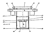
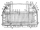
제3도는 본 발명에 따른 드랍 콜렉터의 정면도이다.3 is a front view of the drop collector according to the present invention.
제4도는 제3도의 선 "IV-IV"에서 본 단면도이다.4 is a cross-sectional view taken from the line “IV-IV” of FIG. 3.
제5도는 제4도의 왼쪽부분을 확대하여 상세히 나타낸 것이다.5 is an enlarged view of the left side of FIG.
제6도는 홈통의 시리즈가 중간위치에 있을 때 제3도의 드랍 콜렉터의 일부분을 확대하여 상세히 나타낸 것이다.FIG. 6 shows an enlarged detail of a portion of the drop collector of FIG. 3 when the series of troughs is in the intermediate position.
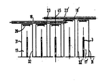
제7도는 제3도의 드랍 콜렉터의 중앙부분을 확대하여 상세히 나타낸 것이다.FIG. 7 shows an enlarged detail of the central portion of the drop collector of FIG. 3.
제8도는 제7도의 드랍 콜렉터의 부분을 평면도로 나타낸 것이다.FIG. 8 shows a portion of the drop collector of FIG. 7 in plan view.
제9도는 제2도의 운반장치를 변형시킨 것이다.9 is a modification of the conveying device of FIG.
제10도는 제4도의 드랍 콜렉터를 변형시킨 것이다.FIG. 10 is a modification of the drop collector of FIG.
* 도면의 주요부분에 대한 부호의 설명* Explanation of symbols for main parts of the drawings
1 : 탱크하우스(tankhouse) 2 : 전해전지1 tank house 2 electrolytic cell
3 : 캐소드 4 : 아노드3: cathode 4: anode
5 : 운반장치 6 : 크레인5: conveying apparatus 6: crane
7 : 운반대 8 : 랙크(rack)7: carrier 8: rack
10,12,19,19`,20,20`,21,21`,22,22`,23,23`,25,25` : 휘일(wheel)10,12,19,19`, 20,20`, 21,21`, 22,22`, 23,23`, 25,25`: wheel
13 : 레일(rail) 14 : 고리13
15 : 드랍 콜렉터 16,16` : 시리즈(series)15:
17,17` : 홈통 18,27,27` : 체인17,17`:
24,24` : 축 26,26` : 모타(motor)24,24`:
28 : 프레임(frame) 29 : 비임(beam)28: frame 29: beam
36,47 : 공간 38 : 전해물36,47: space 38: electrolyte
39 : 출구 40,41 : 저장소39:
42 : 로울러 44 : 볼트42: roller 44: bolt
45 : 수평기하축 46 : 펜트하우스(penthouse)45: horizontal geometry axis 46: penthouse
48 : 소제기48: sweeper
본 발명은 떨어지는 전극 예로서 전해전지로부터 나오는 전극을 운반하는 장치용 드랍 콜렉터(drop collector:덮개가 있는 수집기)에 관한 것이다.The present invention relates to a drop collector (covered collector) for a device for carrying an electrode coming out of an electrolytic cell as an example of a falling electrode.
상기의 장치는 운반대와 운반대에 달려있는 전극용 랙크(rack)로 구성되어 있다.The apparatus consists of a pallet and a rack for electrodes which rests on the pallet.
운반장치용의 공지된 드랍 콜렉터는 한쌍의 큰 접시와 안정위치로부터 작업위치로 접시를 운반하는 운반대에 죄여져 있는 마디로 작동되는 장치로 구성되어 있다.Known drop collectors for conveying devices consist of a pair of large plates and a knuckle operated device clamped to a pallet for conveying the plates from the stable position to the working position.
안정위치에 있을 때 접시는 랙크에 달려있는 전극의 양측에 놓여진다.When in the stable position, the dishes are placed on either side of the electrode on the rack.
그리고 작업위치에 있을 때 접시는 전극 밑에 놓여진다.The dish is then placed under the electrode when in the working position.
이런 형태의 드랍 콜렉터에는 많은 결점이 있다.This type of drop collector has many drawbacks.
즉 운반장치가 설치되어 있는 탱크하우스(thankhouse)에서 작업하는 작업자와 운반장치의 작동자들이 방해를 받게 된다. 본 발명의 목적은 종래의 드랍 콜렉터의 결접을 제거한 드랍 콜렉터를 만드는 것이다.That is, the workers who work in the tankhouse where the transportation device is installed and the operators of the transportation device are disturbed. It is an object of the present invention to make a drop collector which eliminates the conjugation of a conventional drop collector.
본 발명에 따른 드랍 콜렉터에는 하나이상의 출구를 가진 평행홈통의 시리즈(series) 홈통이 전극과 나란하게 전극아래에 놓여지는 하단 작업위치에서부터 홈통의 시리즈가 굽어지는 중간위치를 경유하여 홈통이 겹쳐지는 상단 안정위치로 그리고 이와 반대의 경로로 홈통의 시리즈를 운반하는 장치 홈통의 시리즈가 작업위치에 있을 때 홈통의 출구아래에 놓여지는 저장소 그리고 운반장치의 운반대에 죄여져 있고 운반하는 장치와 저장소가 배치되어 있는 프레임(frame)이 있다.The drop collector according to the present invention has a series of troughs having one or more outlets in which a trough overlaps via an intermediate position in which a series of troughs are bent from a lower working position in which a series trough is placed below the electrode side by side with the electrode. Apparatus for transporting the series of troughs to the stable position and vice versa, when the series of troughs are in the working position, the reservoir is placed below the outlet of the trough and the carriers and the transporting devices and reservoirs are fastened to the carriage of the transporter. There is a frame.
도면에 의거하여 본 발명을 상세히 설명하면 다음과 같다.The present invention will be described in detail with reference to the drawings.
제1도에서, 탱크하우스(1)에 여러줄로 구성된 장방형의 전해전지(2)가 있다.In FIG. 1, there is a rectangular electrolytic cell 2 consisting of several lines in the tank house 1.
각 전해전지(2)에는 한 군의 캐소드(3)와 한 군의 아노드(4)가 교대로 배치되어 있다.In each electrolytic cell 2, a group of
이러한 전극들은 서로서로 일정하게 수직으로 매달려 있고 전지의 종축에 대해 횡으로 매달려 있다.These electrodes are constantly suspended vertically from each other and laterally with respect to the longitudinal axis of the cell.
이것들은 요소(라그(lug)), 지주(suspension-bar), 오프닝(opening)가 있는 금속판으로 구성되어 있다. 전극들은 상기와 같은 요소에 의해 전지속에 매달려지며 랙크에 의해 조종되어진다.These consist of metal plates with elements (lugs), suspension bars, and openings. The electrodes are suspended in the cell by these elements and controlled by racks.
적당한 전해물은 전지(2)를 통해 흐르고 적당한 전류는 전지를 통해 통과한다.Suitable electrolyte flows through the cell 2 and a suitable current passes through the cell.
또 탱크하우스(1)에는 전극용 운반장치(5)도 있다.The tank house 1 also has an electrode conveying apparatus 5.
운반장치(5)에는 운반대(7)가 있는 오버헤드(overhead) 크레인(6)이 있다.In the conveying device 5 there is an overhead crane 6 with a pallet 7.
그리고 운반대(7)에는 안내요소(9)(제3도 참조)가 설치된 랙크(8)가 매달려 있는 공지된 리프팅(lifting)장치(도시되지 않음)가 있다.The carriage 7 also has a known lifting device (not shown) on which the
캐소드용 또는 아노드용 랙크이든지 캐소드 및 아노드용 랙크인 랙크(8)는 수직이동이 가능하다.The
휘일(wheel)(10)이 장치되어 있고 모타(도시되지 않음)에 의해 구동되는 오버헤드 크레인(6)은 전지의 줄에 평행으로 레일(11)상에서 앞뒤로 이동가능하다.The overhead crane 6, equipped with a
휘일(12)이 장치되어 있고 모타(도시되지 않음)에 의해 구동되는 운반대(7)는 전지의 줄에 수직으로 크레인(6)에 부착된 레일(13)상에 앞뒤로 이동가능하다.The carriage 7, equipped with a
전지(2)에 있는 전극(3) 그리고/또는 전극(4)이 새로운 전극으로 교체될 때, 예를 들면 캐소드(3)가 시작하는 캐소드로 교체될 때 운반장치(5)가 작동하기 시작한다.When the
캐소드용 랙크(8) 예로서 고리(14)(제2,3도 참조)가 있는 종래와 같은 랙크가 이때 크레인(6)과 운반대(7)에 의해 전지(2) 위로 가게 된다.A conventional rack with
랙크(8)는 내려가고 캐소드(3)는 고리에 걸려진다.
그리고 캐소드(3)와 함께 랙크가 올려진다.And the rack is raised with the cathode (3).
고리에 걸려진 캐소드(3)와 함께 올려진 랙크(8)는 이때 전기분해를 겪은 캐소드를 취급하는 장소로 크레인(6)과 운반대(7)에 의해 전달된다.The
캐소드(3)가 이런식으로 전달되는 동안 전해액이 떨어지게 된다. 주로 부식성이 강한 액체로 되어 있는 이러한 전해액이 탱크하우스(1)의 바닥이나 탱크하우스에 있는 장치에 떨어지지 않도록 운반장치(5)에 드랍콜렉터(15)가 설치되어 있다.The electrolyte falls off while the
드랍 콜렉터(15)는 평행홈통(17)(17`)으로 구성된 시리즈(16)(16`)로 되어 있다(제3도 참조).The
홈통(17)의 시리즈(16)에는 한쌍의 이동가능한 순환체인(18)이 있다(제2,3,4도 참조).In the
각 체인(18)은 이(tooth)가 있는 한 세트의 휘일(19)(20)(21)(22)(23)(제3,8도 참조)에 의해 운반되어진다.Each
휘일(21)은 축(24)상에 설치되어 있고 축(24)에는 체인(27)을 통해 모타(26)에 의해 구동되는 이가 있는 구동휘일(25)이 있다. 이가 있는 휘일(19)(20)(22)(23)은 축(도시되지 않음)에서 자유로이 회전한다.The wheel 21 is provided on the
상기 축과 모타(26)는 프레임(28)내에 설치되어 있다.The shaft and the
프레임(28)은 비임(beam)(29)을 통해 운반대(7)에 단단하게 죄여져 있다(제2도 참조).Frame 28 is tightly clamped to carriage 7 via beam 29 (see also FIG. 2).
모타(26)에 의해 휘일(21)이 시계방향으로 회전할 때 홈통의 시리즈(18)는 홈통이 전극(3)과 나란하게 전극(3)아래에 놓여지는 하단 작업위치에서부터 중간위치를 경유하여 홈통(17)이 겹쳐지는 상단 안정위치(제3도에서 점선으로 도시되어 있음)로 통과하게 된다.When the wheel 21 is rotated clockwise by the
이후 모타(26)에 의해 휘일(21)이 반대방향으로 회전할 때 시리즈(16)는 체인(18)에 의해 하단 작업위치로 되돌아 오게 된다.The
홈통(17)에는 바닥(30), 종앞벽(longitudinal front wall)(31), 종뒷벽(32)과 양측벽(33)(34)이 있다.The
홈통의 시리즈(16)가 안정위치에있을때 종앞벽(31)은 상단에 놓여지고 종뒷벽(32)은 하단에 놓여진다.When the
제3,6,7도에서 종앞벽(31)의아래부분과 관계홈통의 바로 앞에 있는 홈통의 종뒷벽(32) 사이에 있는 공간(36)위에 펜트하우스(penthouse)가 형성되도록 종앞벽(31)의 윗부분(35)이 홈통(17)의 외부로 기울어져 있다.In FIGS. 3, 6 and 7 the longitudinal
홈통의시리즈(36)가 안정위치에 있을때(제6도 참조) 홈통(17)이 전해물(33)을 보존할 수 있도록 홈통(17)의 종뒷벽(32)의 윗부분(37)이 홈통의 내부로 기울어져 있다.When the
전해물(38)을 배수시킬 수 있는 출구(39)가 홈통(17) 바닥(30)의 양끝에 있다(제4,5도 참조).
전해물(38)은 프레임(28)의 하단 비임인 저장소(40)(41)에 있는 출구(39)를 통해 흐른다.The
출구(39)가 종뒷벽(32)으로부터 먼쪽에 있기 때문에(제8도 참조) 홈통(17)이 안정위치에 있을 때(제6도 참조) 종뒷벽(32), 바닥(30)과 측벽(33)(34)에 의해 전해물(38)용 임시 저장소가 형성되어진다.Since the
홈통(17)에 전해물이 침체되지 않도록 제4도에 도시된 것과 같이 이 홈통은 중앙이 솟아오른 두 부분으로 형성되어져 있다.As shown in FIG. 4, the trough is formed of two parts with a center rising so that the electrolyte does not stagnate in the
체인(18)은 로울러(42)가 있고 속이 빈 베아링 핀 체인이다. 체인(18)의 하단 런 (run)의 로울러(42)를 지지 그리고/또는 안내하는 요소(43)를 저장소(40)(41)에 설치할 수 있다. 홈통(17)의 왼쪽 측벽(33)과 왼쪽 체인(18)은 체인(18)의 연속적인 두 핀을 통과하는 두 개의 볼트(44)에 의해 연결되어 있다. 같은 방식으로 홈통(17)의 오른쪽 측벽(34)과 오른쪽 체인(18)이 연결되었다(제4,5,6도 참조).The
홈통(17)의 왼쪽 시리즈(16)와 같이, 홈통(17`)의 오른쪽 시리즈(16`)도 이가 있는 한 세트의 휘일(19`)(20`)(21`)(22`)(23`)에 의해 운반되어진다.Like the
양 휘일(21`)은 축(24`)에 설치되어 있고 축(24`)에는 체인(27)(27`)을 통해 모타(26`)에 의해 구동되는 이가 있는 구동휘일(25`)이 있다.Both wheels 21 'are provided on a shaft 24' and a toothed drive wheel 25 'which is driven by a motor 26' through
이가 있는 휘일(19`)(20`)(22`)은 축(도시되지 않음)에서 자유로이 회전된다.Teeth 19 ', 20' and 22 'are freely rotated on an axis (not shown).
이 축과 모타(26)는 프레임(28)내에 설치되어 있다.This shaft and the
이가 있는 첫번째 휘일(23`)은 이가 있는 첫번째 휘일(23)의 축에서 자유로이 회전되고, 이가 있는 두번째 휘일(23)은 이가 있는 두번째 휘일(23)의 축에서 자유로이 회전되어진다.The first tooth 23 'with teeth is freely rotated on the axis of the first tooth 23 with teeth, and the second wheel 23 with teeth is freely rotated on the axis of the second wheel 23 with teeth.
그러므로 작업위치에 있을 때(제3,7,8도 참조) 홈통의 시리즈(16)(16`)가 단지 하나의 콜렉터만 형성할 수 있도록 이가 있는 휘일(23)(23`)은 공통으로된 수평기하축(45)을 가지게 된다.Therefore, when in working position (see also 3, 7, 8) the toothed wheels 23, 23` are common so that the
체인(18)사이의 거리와 체인(18`)사이의 거리는 다르다.The distance between the
여기서 체인(18`)사이의 거리가 체인(18)사이의 거리보다 더 크기 때문에 즉 홈통(17`)이 홈통(17)보다 더 길기때문에(제8도 참조) 같은 형태의 볼트(44)로 체인(8)과 체인(18`)에 각각 홈통(17)과 홈통(17`)을 설치할 수 있다.Here, because the distance between the
홈통(17`)과 홈통(17)은 같은 형태로 되어 있다(단 길이는 서로 다르다).The trough 17 'and the
제3,7도에서, 시리즈(16`)가 끝나는 곳에 있는 홈통(17`)은 다른 홈통(17`)과 다르다.In Figs. 3 and 7, the
즉 이 홈통의 종뒷벽(32`)이 이 벽의 양쪽에 뻗어있는 펜트하우스(46)로 둘러싸여져 있다.In other words, the longitudinal back wall 32 'of the trough is surrounded by a penthouse 46 extending on both sides of the wall.
펜트하우스(46)의 윗부분은 시리즈(16)와 시리즈(16`)사이에 있는 공간(47)으로 뻗어있다.The upper portion of the penthouse 46 extends into the space 47 between the
이러한 것이 작업위치에 있을 때 단단한 콜렉터가 형성되어진다. 펜트하우스(46)의 아래부분이 홈통의 바닥(30`)으로 뻗어있기 때문에 홈통의 시리즈(16`)가 안정위치에 있을 때 다른 홈통(17`)이 하는 것과 같이 마지막 홈통도 전해물(38)은 보존 할 수 있다.When this is in the working position, a rigid collector is formed. Since the bottom of the penthouse 46 extends to the bottom 30 'of the trough, the last trough is also electrolyzed (38), as does the
드랍 콜렉터(15)는 다음과 같이 작동한다.The
랙크(8)가 캐소드(3)를 잡기위해 내려지고 캐소드(3)를 실은 랙크(8)가 올려질때 홈통의 시리즈(16)(16`)는 안정위치에 놓여진다.When the
캐소드(3)를 실은 랙크(8)가 높은 운반위치(제2도 참조)에 도달할 때 시리즈(16)(16`)는 작업위치로 보내진다.When the
이때 크레인(6)과 운반대(7)에 의해 부하를 실은 랙크가 운반되기 시작한다.At this time, the rack loaded with the load by the crane 6 and the carriage 7 starts to be conveyed.
운반하는 동안 캐소드(3)에 떨어지는 전해물(38)은 홈통(17)(17`)을 경유하여 저장소(40)(41)로 흐르게 된다.The
공지된 장치(도시되지 않음)를 사용하여 수시로 저장소로부터 전해물을 배수시킬 수 있다.Known devices (not shown) can be used to drain the electrolyte from the reservoir from time to time.
캐소드(3)를 실은 랙크(8)가 목적지에 도달했을 때 홈통의 시리즈(16)(16`)는 다시 안정위치로 되돌아가게 된다. 홈통의 시리즈(16)(16`)가 작업위치에서부터 안정위치로 통과하는 순간이 홈통(17)(17`)에 있는 전해물(38)은 홈통의 종뒷벽(32)(32`)쪽으로 흐른다.When the
그리고 시리즈(16)(16`)가 작업위치로 다시 돌아갈 때까지 종뒷벽(32)(32`), 바닥(30)(30`) 그리고 측벽(33)(34)(33`)(34`)으로 형성되어 있는 저장소에 전해물이 보존되어진다(제6도 참조).And
본 발명의 범위내에서 여러형태로 본 발명을 변형시킬 수 있다. 예로서, 제3도에 도시된 랙크(8)보다 길이가 훨씬 작은 랙크 예로서 16쌍의 고리가 있는 랙크를 운반장치(6)에 설치할 때 홈통의 두 시리즈(16)(16`)대신 단지 하나의 시리즈(16)나 시리즈(16`)만을 설치할 수 있다.The present invention can be modified in many forms within the scope of the present invention. For example, a rack much shorter than the
유럽 특허 제 EP-B-0044594호에 기술된 것과 같은 이중랙크를 운반장치(5)에 설치할 때 제9도에 도시된 것보다 더 긴홈통(17)(17`)을 사용할 수 있다.When installing a double rack such as that described in EP-B-0044594 to the conveying device 5, it is possible to use
제4도에 도시된 것과 같이 이중으로 기울어진 홈통(17)대신 바닥이 한쪽으로만 기울어져 있는 홈통(17)(17`)을 사용할 수 있다.As shown in FIG. 4, a trough 17 (17 ') whose bottom is inclined only to one side may be used instead of a
이러한 홈통의 낮은쪽 끝에 단지 하나의 출구가 있다.There is only one outlet at the lower end of this trough.
그리고 왼쪽 비임(40)은 저장소로 작동하지 않는다.And the
홈통을 청소할 수 있는 소제기(48)(제10도 참조)를 설치할 수 있다.A sweeper 48 (see FIG. 10) capable of cleaning the trough can be provided.
이것은 전해물(38)이 굳어 있을 때 유용하게 사용된다.This is useful when the
Claims (12)
Applications Claiming Priority (2)
| Application Number | Priority Date | Filing Date | Title |
|---|---|---|---|
| LU84654A LU84654A1 (en) | 1983-02-22 | 1983-02-22 | DRIP COLLECTOR FOR AN APPARATUS FOR TRANSPORTING ELECTRODES |
| LU84654 | 1983-02-22 |
Publications (2)
| Publication Number | Publication Date |
|---|---|
| KR840007754A KR840007754A (en) | 1984-12-10 |
| KR900004594B1 true KR900004594B1 (en) | 1990-06-30 |
Family
ID=19730040
Family Applications (1)
| Application Number | Title | Priority Date | Filing Date |
|---|---|---|---|
| KR1019840000459A KR900004594B1 (en) | 1983-02-22 | 1984-02-01 | Drop collector for an apparatus for conveying electrodes |
Country Status (9)
| Country | Link |
|---|---|
| US (1) | US4481963A (en) |
| EP (1) | EP0119330B1 (en) |
| JP (1) | JPS59211586A (en) |
| KR (1) | KR900004594B1 (en) |
| AU (1) | AU562756B2 (en) |
| CA (1) | CA1227164A (en) |
| DE (1) | DE3370658D1 (en) |
| FI (1) | FI74307C (en) |
| LU (1) | LU84654A1 (en) |
Families Citing this family (7)
| Publication number | Priority date | Publication date | Assignee | Title |
|---|---|---|---|---|
| JPH01255016A (en) * | 1988-04-01 | 1989-10-11 | Shimadzu Corp | Gas density stabilizer |
| JPH06139915A (en) * | 1992-10-23 | 1994-05-20 | Rohm Co Ltd | Protective device for overvoltage and overcurrent |
| GB9815171D0 (en) * | 1998-07-13 | 1998-09-09 | Eastman Kodak Co | An arrangement for, and method of removing a component from immersion in a liquid |
| US6780366B2 (en) * | 2002-08-15 | 2004-08-24 | Mentor Corporation | Drip retainer |
| GB0404343D0 (en) * | 2004-02-27 | 2004-03-31 | Rpl Holdings Ltd | Refrigerant composition |
| CN102485813A (en) * | 2010-12-01 | 2012-06-06 | 成都市新津托展油墨有限公司 | Preparation method of alcohol water-soluble plastic intaglio plate golden oil |
| CN110965103B (en) * | 2019-12-26 | 2021-11-12 | 新兴国琳铝业有限公司 | Composite anodic oxidation surface process and treatment device for aluminum profile |
Family Cites Families (4)
| Publication number | Priority date | Publication date | Assignee | Title |
|---|---|---|---|---|
| US2417634A (en) * | 1944-12-30 | 1947-03-18 | Frank J Cozzoli | Dripless tray for ampule washing machines |
| GB1348490A (en) * | 1970-06-19 | 1974-03-20 | Oxy Metal Finishing Corp | Wet processing installation |
| JPS548162B2 (en) * | 1973-07-07 | 1979-04-13 | ||
| US4248353A (en) * | 1979-03-16 | 1981-02-03 | Nassau Recycle Corporation | Apparatus for collecting drippings from a wet load carried by a crane |
-
1983
- 1983-02-22 LU LU84654A patent/LU84654A1/en unknown
- 1983-06-08 US US06/502,215 patent/US4481963A/en not_active Expired - Fee Related
- 1983-12-23 EP EP83201838A patent/EP0119330B1/en not_active Expired
- 1983-12-23 DE DE8383201838T patent/DE3370658D1/en not_active Expired
-
1984
- 1984-02-01 KR KR1019840000459A patent/KR900004594B1/en not_active IP Right Cessation
- 1984-02-01 FI FI840410A patent/FI74307C/en not_active IP Right Cessation
- 1984-02-06 AU AU24098/84A patent/AU562756B2/en not_active Ceased
- 1984-02-10 CA CA000447220A patent/CA1227164A/en not_active Expired
- 1984-02-22 JP JP59032270A patent/JPS59211586A/en active Granted
Also Published As
| Publication number | Publication date |
|---|---|
| AU2409884A (en) | 1984-08-30 |
| FI74307C (en) | 1988-01-11 |
| CA1227164A (en) | 1987-09-22 |
| FI74307B (en) | 1987-09-30 |
| KR840007754A (en) | 1984-12-10 |
| LU84654A1 (en) | 1984-11-08 |
| EP0119330B1 (en) | 1987-04-01 |
| DE3370658D1 (en) | 1987-05-07 |
| FI840410A0 (en) | 1984-02-01 |
| FI840410A (en) | 1984-08-23 |
| JPS59211586A (en) | 1984-11-30 |
| EP0119330A1 (en) | 1984-09-26 |
| AU562756B2 (en) | 1987-06-18 |
| US4481963A (en) | 1984-11-13 |
| JPS6312152B2 (en) | 1988-03-17 |
Similar Documents
| Publication | Publication Date | Title |
|---|---|---|
| CN111519235B (en) | Barrel-plating production line | |
| KR900004594B1 (en) | Drop collector for an apparatus for conveying electrodes | |
| FI75606B (en) | RENGOERINGSFOERFARANDE OCH -ANORDNING FOER KATOD- OCH / ELLER ANODPLATTOR. | |
| CN101153403A (en) | Hook of electrode plate conveying device | |
| FI87659B (en) | FOERFARANDE FOER ELEKTROLYTISK UTVINNING AV EN METALL, RAMSTOMME FOER EN ELEKTRODENHET OCH KONSTRUKTION FOER HOPSAETTNING AV ANODPLAOTAR OCH KATODPLAOTAR | |
| FI107941B (en) | Apparatus for transferring electrodes in electrolytic refining of metals | |
| JP2749453B2 (en) | Equipment for processing printed circuit boards | |
| CN112011808A (en) | Discharging and loading integrated system of electrolytic cell and discharging and loading control method of electrolytic cell | |
| US4233145A (en) | Device for the processing of pourable bulk material | |
| US3887094A (en) | Conveyance of electrodes for electrolytic cells in electrorefining | |
| CA1182425A (en) | Process and apparatus for replacing cathodes | |
| GB1480558A (en) | Electroplating apparatus | |
| US4425211A (en) | Device for electrodeposition of aluminum | |
| CN210711774U (en) | Discharging and loading integrated system of electrolytic cell | |
| CN215828889U (en) | Intelligent access groove system for electrolytic manganese cathode plate | |
| DD202460A5 (en) | DEVICE FOR GALVANIC SEPARATION OF ALUMINUM | |
| US2115004A (en) | Electrolytic apparatus | |
| CN212357414U (en) | Lead electrolysis workshop | |
| CN215754642U (en) | Anode plate receiving and conveying device | |
| CN215363240U (en) | Novel continuous type circulation lifting machine | |
| CN215209589U (en) | Galvanized workpiece hanging rack | |
| US859565A (en) | Apparatus for detinning tin-scrap. | |
| US1095748A (en) | Electrolytic apparatus. | |
| SU505600A1 (en) | Automated warehouse | |
| SU513124A1 (en) | Shelving Rack Sheet Products |
Legal Events
| Date | Code | Title | Description |
|---|---|---|---|
| A201 | Request for examination | ||
| G160 | Decision to publish patent application | ||
| E701 | Decision to grant or registration of patent right | ||
| N231 | Notification of change of applicant | ||
| GRNT | Written decision to grant | ||
| FPAY | Annual fee payment |
Payment date: 19930628 Year of fee payment: 4 |
|
| LAPS | Lapse due to unpaid annual fee |