KR900002513B1 - Passive fiber optic multiplexer - Google Patents
Passive fiber optic multiplexer Download PDFInfo
- Publication number
- KR900002513B1 KR900002513B1 KR8205069A KR820005069A KR900002513B1 KR 900002513 B1 KR900002513 B1 KR 900002513B1 KR 8205069 A KR8205069 A KR 8205069A KR 820005069 A KR820005069 A KR 820005069A KR 900002513 B1 KR900002513 B1 KR 900002513B1
- Authority
- KR
- South Korea
- Prior art keywords
- optical fiber
- optical fibers
- length
- wavelength
- optical
- Prior art date
Links
Images


Classifications
-
- G—PHYSICS
- G02—OPTICS
- G02B—OPTICAL ELEMENTS, SYSTEMS OR APPARATUS
- G02B6/00—Light guides; Structural details of arrangements comprising light guides and other optical elements, e.g. couplings
- G02B6/24—Coupling light guides
-
- G—PHYSICS
- G02—OPTICS
- G02B—OPTICAL ELEMENTS, SYSTEMS OR APPARATUS
- G02B6/00—Light guides; Structural details of arrangements comprising light guides and other optical elements, e.g. couplings
- G02B6/24—Coupling light guides
- G02B6/26—Optical coupling means
- G02B6/28—Optical coupling means having data bus means, i.e. plural waveguides interconnected and providing an inherently bidirectional system by mixing and splitting signals
- G02B6/293—Optical coupling means having data bus means, i.e. plural waveguides interconnected and providing an inherently bidirectional system by mixing and splitting signals with wavelength selective means
- G02B6/29331—Optical coupling means having data bus means, i.e. plural waveguides interconnected and providing an inherently bidirectional system by mixing and splitting signals with wavelength selective means operating by evanescent wave coupling
- G02B6/29332—Wavelength selective couplers, i.e. based on evanescent coupling between light guides, e.g. fused fibre couplers with transverse coupling between fibres having different propagation constant wavelength dependency
-
- G—PHYSICS
- G02—OPTICS
- G02B—OPTICAL ELEMENTS, SYSTEMS OR APPARATUS
- G02B6/00—Light guides; Structural details of arrangements comprising light guides and other optical elements, e.g. couplings
- G02B6/24—Coupling light guides
- G02B6/26—Optical coupling means
- G02B6/28—Optical coupling means having data bus means, i.e. plural waveguides interconnected and providing an inherently bidirectional system by mixing and splitting signals
- G02B6/2804—Optical coupling means having data bus means, i.e. plural waveguides interconnected and providing an inherently bidirectional system by mixing and splitting signals forming multipart couplers without wavelength selective elements, e.g. "T" couplers, star couplers
- G02B6/2821—Optical coupling means having data bus means, i.e. plural waveguides interconnected and providing an inherently bidirectional system by mixing and splitting signals forming multipart couplers without wavelength selective elements, e.g. "T" couplers, star couplers using lateral coupling between contiguous fibres to split or combine optical signals
- G02B6/2826—Optical coupling means having data bus means, i.e. plural waveguides interconnected and providing an inherently bidirectional system by mixing and splitting signals forming multipart couplers without wavelength selective elements, e.g. "T" couplers, star couplers using lateral coupling between contiguous fibres to split or combine optical signals using mechanical machining means for shaping of the couplers, e.g. grinding or polishing
- G02B6/283—Optical coupling means having data bus means, i.e. plural waveguides interconnected and providing an inherently bidirectional system by mixing and splitting signals forming multipart couplers without wavelength selective elements, e.g. "T" couplers, star couplers using lateral coupling between contiguous fibres to split or combine optical signals using mechanical machining means for shaping of the couplers, e.g. grinding or polishing couplers being tunable or adjustable
-
- G—PHYSICS
- G02—OPTICS
- G02B—OPTICAL ELEMENTS, SYSTEMS OR APPARATUS
- G02B6/00—Light guides; Structural details of arrangements comprising light guides and other optical elements, e.g. couplings
- G02B6/24—Coupling light guides
- G02B6/26—Optical coupling means
- G02B6/28—Optical coupling means having data bus means, i.e. plural waveguides interconnected and providing an inherently bidirectional system by mixing and splitting signals
- G02B6/293—Optical coupling means having data bus means, i.e. plural waveguides interconnected and providing an inherently bidirectional system by mixing and splitting signals with wavelength selective means
- G02B6/29379—Optical coupling means having data bus means, i.e. plural waveguides interconnected and providing an inherently bidirectional system by mixing and splitting signals with wavelength selective means characterised by the function or use of the complete device
- G02B6/2938—Optical coupling means having data bus means, i.e. plural waveguides interconnected and providing an inherently bidirectional system by mixing and splitting signals with wavelength selective means characterised by the function or use of the complete device for multiplexing or demultiplexing, i.e. combining or separating wavelengths, e.g. 1xN, NxM
-
- G—PHYSICS
- G02—OPTICS
- G02B—OPTICAL ELEMENTS, SYSTEMS OR APPARATUS
- G02B6/00—Light guides; Structural details of arrangements comprising light guides and other optical elements, e.g. couplings
- G02B6/24—Coupling light guides
- G02B6/26—Optical coupling means
- G02B6/28—Optical coupling means having data bus means, i.e. plural waveguides interconnected and providing an inherently bidirectional system by mixing and splitting signals
- G02B6/293—Optical coupling means having data bus means, i.e. plural waveguides interconnected and providing an inherently bidirectional system by mixing and splitting signals with wavelength selective means
- G02B6/29379—Optical coupling means having data bus means, i.e. plural waveguides interconnected and providing an inherently bidirectional system by mixing and splitting signals with wavelength selective means characterised by the function or use of the complete device
- G02B6/29395—Optical coupling means having data bus means, i.e. plural waveguides interconnected and providing an inherently bidirectional system by mixing and splitting signals with wavelength selective means characterised by the function or use of the complete device configurable, e.g. tunable or reconfigurable
Abstract
Description
제 1 도는 각각의 기부의 각각의 아치형 홈에 장착된 한쌍의 광학섬유 가닥을 도시한, 본 발명에 멀티플렉서로서 사용된 광학 섬유 결합기이 횡단면도.1 is a cross-sectional view of an optical fiber combiner used as a multiplexer in the present invention, showing a pair of optical fiber strands mounted in each arcuate groove of each base.
제 2 도는 및 제 3 도는 각각 선 2-2 및 선 3-3을 따라 절취하여 도시한, 제 1 도의 결합기의 횡단면도.2 and 3 are cutaway views taken along lines 2-2 and 3-3, respectively.
제 4 도는 관련된 광학 섬유의 장착 부재 및 광학 섬유의 타원형 접촉 표면을 도시하기 위해 다른 기부로부터 분리된 제 1 도의 결합기의 하부기부를 도시한 사시도.4 is a perspective view showing the bottom portion of the coupler of FIG. 1 separated from the other base to show the mounting member of the associated optical fiber and the elliptical contact surface of the optical fiber.
제 5 도는 상호 작용 지역에 중첩된 한쌍의 광학 섬유의 미소 지역을 도시한 개략도.5 is a schematic diagram showing a microregion of a pair of optical fibers superimposed on an interaction region.
제 6 도는 결합기의 파라메타로서, 곡선 반경, 코어 간격 및 상호 작용 길이를 도시한 제 1 도의 결합기의 개략도.6 is a schematic diagram of the coupler of FIG. 1 showing the radius of curvature, core spacing and interaction length as parameters of the coupler.
제 7 도는 "등가"결합기의 개략도.7 is a schematic representation of an "equivalent" coupler.
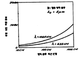
제 8 도는 소정의 광학 섬유 코어 간격에 대한 상호 작용 길이의 함수인, 소정의 파장의 광선 신호에 대한 표준 결합 전력의 그래프도.8 is a graphical representation of standard coupling power for a light signal of a predetermined wavelength as a function of interaction length for a given fiber optic core spacing.
제 9 도는 다른 광학 섬유 코어 간격에 대한 상호 작용 길이의 함수인, 제 8 도와 동일한 파장의 광선 신호에 대한 표준 결합 전력의 그래프도.9 is a graphical representation of standard coupling power for a light signal of the same wavelength as that of FIG. 8 as a function of interaction length for different optical fiber core spacings.
제 10 도는 최소 광학 코어 간격(중첩된 간격 표면)의 함수인, 소정의 파장의 광선에 대한 표준 결합 전력의 그래프도.10 is a graphical representation of standard combined power for light rays of a predetermined wavelength, as a function of minimum optical core spacing (overlapping spacing surface).
제 11 도는 5 미크론(micron)의 최소 간격을 갖고 있는 결합기에 대한 유효 상호 작용 길이 대 광학 섬유 곡선 반경의 그래프도.11 is a graphical representation of the effective interaction length versus the optical fiber curve radius for a coupler with a minimum spacing of 5 microns.
제 12 도는 5 미크론의 최소 간격과 25㎝ 및 100㎝의 광학 섬유의 곡선 반경을 갖고 있는 한쌍의 결합기에 대한 신호 파장의 함수인 유효 상호 작용 길이의 그래프도.12 is a graphical representation of the effective interaction length as a function of signal wavelength for a pair of couplers having a minimum spacing of 5 microns and a curved radius of optical fibers of 25 cm and 100 cm.
제 13 도는 접촉 표면들이 측방향으로 편기(offset)된 상태를 도시한, 연마 후의 광학 섬유의 타원형 표면들의 개략도.13 is a schematic diagram of elliptical surfaces of an optical fiber after polishing, showing a state in which the contact surfaces are laterally offset.
제 14 도는 결합기내의 2개의 중첩된 광학 섬유의 제 1 직교 방향의 물리적 관계를 도시한 개략도.14 is a schematic diagram showing the physical relationship in the first orthogonal direction of two superimposed optical fibers in a combiner.
제 15 도는 제 14 도의 그래프의 직교 방향으로 취해진 제 14 도의 광학 섬유의 개략도.FIG. 15 is a schematic representation of the optical fiber of FIG. 14 taken in the orthogonal direction of the graph of FIG. 14. FIG.
제 16 도는 편기된 광학 섬유에 대한, 제 14 도와 유사한 개략도.FIG. 16 is a schematic similar to FIG. 14 for a knitted optical fiber. FIG.
제 17 도는 제 16 도의 편기된 광학 섬유에 대한, 제 1 도와 유사한 개략도.17 is a schematic view similar to the first diagram for the knitted optical fiber of FIG. 16. FIG.
제 18 도는 633㎝의 파장, 25㎝ 및 100㎝의 반경, 및 5 미크론의 최소 광학 섬유 간격을 갖고 있는 한쌍의 결합기에 대한 수평 광학 섬유 편기의 함수인, 본 발명에 따른 결합기의 유효 상호작용 길이를 도시한 그래프도.18 shows the effective interaction length of a coupler according to the invention, which is a function of the horizontal optical fiber knitting machine for a pair of couplers having a wavelength of 633 cm, radius of 25 cm and 100 cm, and a minimum optical fiber spacing of 5 microns. Graph showing the.
제 19 도는 제 1 최소 광학 섬유 코어 간격에 대한 측방향 편기의 함수인 표준 결합 전력의 그래프도.19 is a graphical representation of standard binding power as a function of lateral knitting against the first minimum fiber optic core spacing.
제 20 도는 제 2 광학 섬유 코어 간격에 대한 측방향 편기의 함수인 표준 결합 전력의 그래프도.20 is a graphical representation of standard binding power as a function of lateral knitting for a second fiber optic core spacing.
제 21 도는 제 3 광학 섬유 코어 간격에 대한 측방향 편기의 함수인 표준 결합 전력의 그래프도.FIG. 21 is a graphical representation of standard binding power as a function of lateral knitting for a third optical fiber core spacing.
제 22 도는 시스템 효율 손실이 표준 결합 전력의 모든 범위에 걸쳐서 균일한 것을 나타내는 일예의 결합기에 대한 측방향 편기의 함수인 표준 결합 전력(a)와 측방향 편기의 함수인 시스템 효율 손실(b)의 그래프도.22 shows the system efficiency loss (b) as a function of the lateral knitting and the standard coupling power (a) which is a function of the lateral knitting for an example coupler showing that the system efficiency loss is uniform across all ranges of the standard coupling power. Graph too.
제 23 도는 접촉 표면이 종방향으로 편기된 상태를 도시한, 광학 섬유의 접촉 표면의 개략도.23 is a schematic view of a contact surface of an optical fiber, showing a state in which the contact surface is knitted in the longitudinal direction.
제 24 도는 접촉 표면들이 회전 가능하게 편기된 상태를 도시한, 광학 섬유의 접촉 표면의 개략도.24 is a schematic view of a contact surface of an optical fiber, showing a state in which the contact surfaces are rotatably knitted.
제 25 도는 단파장을 갖고 있는 본 발명의 결합기 내에 결합된 광학 섬유들 사이의 E전계 중첩 상태를 도시한 개략도.25 is a schematic diagram showing the E-field superposition state between optical fibers bonded in the combiner of the present invention having a short wavelength.
제 26 도는 중간파장에 대한 E전계 중첩 상태를 도시한, 제 25 도와 유사한 도면.FIG. 26 is a view similar to FIG. 25 showing the E-field superposition state for intermediate wavelengths. FIG.
제 27 도는 장파장에 대한 E전계 중첩 상태를 도시한, 제 25 도 및 제 26 도와 유사한 도면.FIG. 27 is a view similar to FIGS. 25 and 26 showing the electric field superposition state for long wavelengths.
제 28 도는 표준 주파수의 함수인 코어/피복물 경계 및 코어 전력/총전력에서의 평균 전력 밀도의 그래프도.28 is a graphical representation of average power density at core / cover boundary and core power / total power as a function of standard frequency.
제 29 도는 25㎝의 광학 섬유 반경을 갖고 있는 제 1 형태의 광학 섬유 결합기에 대한 결합 길이 대 신호 파장을 도시한 도표.FIG. 29 shows a plot of signal length versus signal wavelength for an optical fiber coupler of the first type having an optical fiber radius of 25 cm.
제 30 도는 25㎝의 광학 섬유 반경을 갖고 있는 제 2 형태의 광학 섬유 결합기에 대한 결합 길이 대 신호 파장을 도시한 도표.30 is a plot showing the signal length versus signal wavelength for a second type of optical fiber coupler having an optical fiber radius of 25 cm.
제 31 도는 본 발명의 멀티플렉서를 도시한 개략도.31 is a schematic diagram illustrating a multiplexer of the present invention.
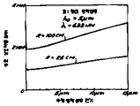
제 32 도는 4 미크론의 최소 광학 섬유 간격, 0미크론의 편기 및 25㎝의 광학 섬유 반경을 갖고 있는 제 1의 형태의 광학 섬유 결합기에 대한 상대 결합전력 대 신호 파장을 도시한 도표.FIG. 32 is a plot showing relative coupling power versus signal wavelength for an optical fiber combiner of the first type having a minimum optical fiber spacing of 4 microns, a knitting machine of 0 microns and an optical fiber radius of 25 cm.
제 33 도는 제 32 도와 유사하지만 200㎝의 광학 섬유 곡선 반경을 갖고 있는 상대 결합 전력 대 신호 파장을 도시한 도표.FIG. 33 is a plot showing relative coupling power versus signal wavelength, similar to FIG. 32, but with an optical fiber curve radius of 200 cm.
제 34 도는 상이한 최소 광학 섬유 간격들을 갖고 있는 여러 결합기에 대한 결합 길이 대 신호 파장에 의해 나누어진 상호 작용 길이의 상(quotient)을 도시한 도표.34 shows a plot of interaction length divided by coupling length versus signal wavelength for various couplers having different minimum optical fiber spacings.
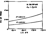
제 35 도는 4 미크론의 최소 광학 섬유 간격, 200㎝의 광학 섬유 반경, 및 선택가능한 광학 섬유 편기를 갖고 있는 제 1 형태의 광학 섬유 결합기에 대한 상대 결합 전력 대 신호 파장을 도시한 도표.FIG. 35 is a plot showing relative binding power versus signal wavelength for a first type of optical fiber combiner with a minimum optical fiber spacing of 4 microns, an optical fiber radius of 200 cm, and an optional optical fiber knitting machine.
제 36 도는 결합기를 바람직한 결합 효율에 동조시키도록 접촉 표면의 편기를 조정하기 위해 마이크로미터를 갖고 있는 동조 장치의 사시도.36 is a perspective view of a tuning device having a micrometer to adjust the knitting of the contact surface to tune the coupler to the desired coupling efficiency.
제 37 도는 본 발명의 멀티플렉싱 결합기를 사용하는 다중 파장 멀티플렉싱 시스템의 개략도.37 is a schematic diagram of a multiple wavelength multiplexing system using the multiplexing combiner of the present invention.
* 도면의 주요부분에 대한 부호의 설명* Explanation of symbols for main parts of the drawings
10 : 결합기 10a 및 10b : 결합기 절반부10: combiner 10a and 10b: combiner half
12 : 광학 섬유 12a 및 12b : 광학 섬유 가닥12 optical fiber 12a and 12b optical fiber strand
13 a 13b : 홈 14a 및 14b : 대향 표면13a 13b:
15a 및 15b : 코어 16a 및 16b : 블록15a and 15b:
17a 및 17b : 대향표면 18a 및 18b : 타원형 접촉 표면17a and 17b:
32 : 상호 작용 영역 33 : 임계영역32: interaction area 33: critical area
34 : 미소 지역 38 : 접착제34: micro area 38: adhesive
70 : 동조 장치 71 : 마이크 로미터 캐리지(carriage)70: tuning device 71: micrometer carriage
72 : 계단식 U형 채널 74 : 저부72: cascaded U-channel 74: bottom
76 : 상부 78 : 리테이너(retainer)76: top 78: retainer
80 : 마이크로미터(micrometer)80: micrometer
본 발명은 수동 광학 섬유 멀티플렉서에 관한 것으로, 특히 단일 광학 섬유상에 상이한 광학 섬유에 의해 이송된 상이한 광선 파장의 다수의 신호들을 결합하거나, 한쌍의 광학 섬유 상에 계속 전달하기 위해 공통광학 섬유에 이송된 상이한 광선 파장의 신호들을 분리시키는데 유용한 파장 응답 멀티플레서에 관한 것이다.FIELD OF THE INVENTION The present invention relates to passive optical fiber multiplexers, in particular to combining multiple signals of different light wavelengths carried by different optical fibers on a single optical fiber, or to a common optical fiber for continuing delivery on a pair of optical fibers. A wavelength response multiplexer useful for separating signals of different light wavelengths.
종래에, 광학 섬유 멀티플렉싱은 한쌍의 도파관이 전압 응답 굴절률을 갖고 있는 석영 물지로 둘러 싸여 있는 능동 시스템을 사용함으로써 이루어졌다. 이러한 능동 시스템은 양호한 작용을 하기 위해 사용 중에 조심스럽게 동조시키고, 조정해야할 뿐만 아니라 전력을 인가시켜야 한다.Conventionally, optical fiber multiplexing has been accomplished by using an active system in which a pair of waveguides are surrounded by quartz material with a voltage response refractive index. These active systems must be carefully tuned and adjusted during use to apply good power, as well as to apply power.
이 능동 시스템들 이외에도, 도파관들이 결합될 주파수를 제외한 모든 주파수에서 상이한 위상 전달 상수를 갖고 있어 모든 다른 주파수들로부터 이 주파수를 분리시키는, 1976년 5월 18일자로 하여된 헨리 에프. 테일러(Henry F. Taylor)의 특허 제 3,957,341 호에 기술된 바와같은 수동 주파수 선택 결합기가 고안되어 있다. 그러나, 이러한 시스템들은 바람직한 주파수 분리를 하기 위해 조심스럽게 물질을 선택해야 하고, 광범위한 주파수 대역에 걸쳐서 광학 신호들을 분리시키기 위해 제조 중 또는 제조후에 이 시스템 자체를 조정할 수가 없게 된다.In addition to these active systems, Henry F., dated May 18, 1976, which has different phase transfer constants at all frequencies except the frequency at which the waveguides are to be coupled, separating them from all other frequencies. A passive frequency selective coupler is devised as described in Henry F. Taylor, Patent No. 3,957,341. However, these systems must carefully select materials to achieve the desired frequency separation, and the system itself cannot be adjusted during or after manufacturing to separate optical signals over a wide frequency band.
2 개의 동일한 병렬 유전성 도파관 사이의 광선 에너지 결합에 따른 주파수는 다수의 발간된 과학 논문지에 이론적으로 기술되어 있으나, 수동 시스템내의 광선 에너지의 결합은 일반적으로, 주파수 선택성이 비교적 명확하지 않기 때문에, 즉 이러한 시스템은 비교적 약한 해상도(resolution)만을 발생시키기 때문에, 대부분의 경우에 비실용적이다.Although the frequency of light energy coupling between two identical parallel dielectric waveguides has been theoretically described in many published scientific journals, the coupling of light energy in passive systems is generally because the frequency selectivity is relatively unclear, ie such The system is only impractical in most cases because it produces only relatively weak resolutions.
그러므로, 고해상도 주파수 선택을 제공하고 광범위한 주파수 대역내에서 선택된 주파수에 대한 이러한 해상도를 제공하도록 조정할 수 있는 수동 광학 결합기가 필요하다. 그러므로, 대부분의 광학 시스템에서는, 다중 신호들이 상이한 광학 주파수에서 단일 광학 섬유상에 동시에 전송되어, 광학 섬유의 전송 능력을 증배시키는 것이 바람직하다. 이러한 시스템에 사용하기 위한 멀티플렉서들은 특정한 사용 목적으로 단일의 전송 주파수가 검출 될 수 있도록 상이한 주파수들을 멀티플렉싱 또는 분리하기 위해 최소한 제조시에 양호하게 동조될 수 있다. 이러한 멀티플렉싱은 시스템 효율이 멀티플렉서내의 손실에 의해 부당하게 제한되지 않도록 최저 가능 시스템 효율 손실로 이루어지는 것이 바람직하다.Therefore, there is a need for a passive optical combiner that can provide high resolution frequency selection and can be adjusted to provide such resolution for selected frequencies within a wide frequency band. Therefore, in most optical systems, it is desirable for multiple signals to be transmitted simultaneously on a single optical fiber at different optical frequencies, thus multiplying the transmission capability of the optical fibers. Multiplexers for use in such a system can be well tuned at least at the time of manufacture to multiplex or separate the different frequencies so that a single transmission frequency can be detected for a particular purpose of use. Such multiplexing preferably consists of the lowest possible system efficiency loss so that system efficiency is not unduly limited by losses in the multiplexer.
본 발명은 제조시에 동조될 수 있고 소정의 광학 주파수 그룹을 실제적으로 분리시키거나 결합시키기 위한 광학 섬유 멀티플렉서를 제공한다. 이전의 수동 멀티플렉서와는 달리, 본 발명은 종래 기술에서 필요했던 바와같이 멀티플렉서 제한으로 인해 시스템을 억제시키지 않고, 광학 시스템의 시방서에 부합하도록 광학 멀티플렉서를 용이하게 제조하기 위해 정확한 동조 능력에 따라 고해상도를 제공한다.The present invention provides an optical fiber multiplexer that can be tuned at the time of manufacture and substantially separates or combines certain optical frequency groups. Unlike previous passive multiplexers, the present invention does not inhibit the system due to multiplexer limitations, as required by the prior art, and provides high resolution according to the precise tuning capability to easily fabricate the optical multiplexer to meet the specifications of the optical system. to provide.
본 발명의 멀티플렉서는 한쌍의 단일 모우드 광학 섬유가 미소 지역 결합을 하고 선택된 주파수에서 과대 결합을 하도록 선택 가능한 상호 작용 길이를 통해 서로 인접하여 배치된 단일 모우드 광학 섬유 결합기를 사용한다. 피복된 단일 모우드 광학 섬유가 결합기를 구성할 때 사용되면, 이 광학 섬유는 광학 물질의 각각의 가닥을 장착시키기 위해 각각의 아치형 홈을 갖고 있는 한쌍의 기부 또는 블록(block)내에 장착 된다. 물질은 바람직한 량의 광학 섬유 물질이 제거될 때까지 블록 및 가닥들을 동시에 연마함으로써 제거된다. 그 다음, 블록들은 대향 관계로 배치되고, 가득들은 서로 밀접하게 배치되며, 광학 섬유의 절단 부분들은 접촉 관계로 배치된다.The multiplexer of the present invention employs a single mode optical fiber combiner disposed adjacent to each other via a selectable interaction length such that a pair of single mode optical fibers make microregion coupling and overbond at a selected frequency. When coated single mode optical fibers are used to construct the combiner, the optical fibers are mounted in a pair of bases or blocks having respective arcuate grooves for mounting each strand of optical material. The material is removed by simultaneously grinding the blocks and strands until the desired amount of optical fiber material is removed. The blocks are then placed in opposing relationship, the fills are placed closely together, and the cut portions of the optical fiber are placed in contact relationship.
적당한 미소 지역 결합을 하기 위해, 광학 섬유로부터 제거된 물질의 량은 광학 섬유의 코어 부분들 사이의 간격이 선정된 "임계 지역"내에 있도록 조심스럽게 제어되어야 한다. 이것은 각각의 가닥이 다른 가닥으로부터의 미소 지역 에너지의 상당한 부분을 수용하게 하여, 결합은 에너지가 크게 손실되지 않고도 달성된다.In order to make proper micro area bonding, the amount of material removed from the optical fiber must be carefully controlled so that the spacing between the core portions of the optical fiber is within a predetermined "critical area". This allows each strand to receive a significant portion of the micro-regional energy from the other strands so that bonding is achieved without significant loss of energy.
본 발명의 멀티플렉서에 사용된 결합기는 선택된 파장에서의 결합 전력이 시스템 효율 손실에 크게 악영향을 미치지 않고서 선정된 범위를 통해 바람직한 값으로 변화될 수 있도록 조정될 수 있다. 이러한 결합기 조정 또는 결합기 동조는 각각의 접촉 표면이 서로 미끄러질 수 있게 편기되도록 광학 섬유를 이동시킴으로써 달성될 수 있다.The coupler used in the multiplexer of the present invention can be adjusted so that the coupling power at the selected wavelength can be changed to a desired value through the selected range without significantly adversely affecting the system efficiency loss. This coupler adjustment or coupler tuning can be accomplished by moving the optical fibers such that each contact surface is knitted so that they can slip on each other.
이 결합기 형태의 중요한 특징은 시스템 효율 손실을 낮게 할 수 있다는 것이다. 실험결과, 시스템 효율 손실이 0.2db로 얻어졌는데, 통상적으로는 0.5db이다. 또한, 결합기는 모든 결합 전력이 결합기의 출력측에 전달되는 고도의 방향성을 갖고 있다. 실험결과, 방향성 결합 전력은 역방향성 결합 전력 보다 60db가 더 컸다. 결합기는 또한, 우수한 편광 응답을 갖고 있으므로, 동일한 편광으로 광선을 통과시킨다.An important feature of this coupler type is that it can lower the system efficiency loss. As a result of the experiment, the system efficiency loss was obtained at 0.2db, which is usually 0.5db. The combiner also has a high degree of directivity in which all combined power is delivered to the output side of the combiner. Experimental results show that the directional coupling power is 60db larger than the reverse coupling power. The coupler also has an excellent polarization response, thus allowing light to pass through the same polarization.
기부 또는 블록내에 있는 아치형 홈의 반경은 선정된 "상호 작용 길이"를 제공하도록 선택될 수 있다. 본 명세서에 사용된 바와같이, "상호 작용 길이"란 용어는 한 광학 섬유의 코어를 다른 광학 섬유의 미소 지역내에 배치시키는 광학 섬유의 축 방향의 길이를 의미한다.The radius of the arcuate groove in the base or block may be selected to provide a predetermined “interaction length”. As used herein, the term "interaction length" means the length in the axial direction of an optical fiber that places the core of one optical fiber within the micro area of the other optical fiber.
단일 모우드 광학 섬유내의 미소 지역의 형태는 파장에 따라 변한다. 그러므로, 광학 섬유 결합기에서, 제 2 광학 섬유의 코어 위치에서의 제 1 광학 섬유의 미소 지역의 세기는 제 1 광학 섬유에 의해 전송된 광선의 파장에 따라 변한다. 이 사실은 광학 섬유 결합기 내의 상이한 파장들에 대해 상이한 결합 효율을 발생 시키므로 상이한 광선 파장들에 대해 상이한 "결함 길이"를 발생시킨다. 본 명세서에 사용된 바와같이, "결합 길이"는 소정의 파장의 광선을 한 광학 섬유로부터 다른 광학 섬유로 100%결합시키는데 필요한 "상호작용 길이"내의 광학 섬유 축에 평행한 길이를 의미한다. 선정된 파장에서의 결합기의 상호 작용 길이가 결합 길이와 같으며, 결합기는 광선을 제 1광학 섬유로부터 제 2 광학 섬유로 100%이송하게 된다. 그러나, 선정된 파장에서의 상호 작용 길이가 결합 길이의 2 배이면, 모든 광선 에너지는 제 1 광학 섬유로부터 제 2 광학 섬유에 결합된 다음, 제 1 광학 섬유내의 결합기에서 나오도록 제 2 광석 섬유로부터 다시 제 1 광학 섬유로 결합되어, 0의 순수 결합효율을 발생시킨다. 이 설명으로부터, 상호작용 길이가 선정된 주파수에서의 결합 길이의 짝수 배이면, 결합기의 결합 효율이 0으로 된다는 것을 알 수 있다. 한편, 상호 작용 길이가 소정의 주파수에서늬 결합 길이의 홀수배이면, 결합기의 결합효율은 100%로 된다.The shape of the microregions within a single mode optical fiber varies with wavelength. Therefore, in the optical fiber combiner, the intensity of the micro area of the first optical fiber at the core position of the second optical fiber varies with the wavelength of the light beam transmitted by the first optical fiber. This fact gives rise to different coupling efficiencies for different wavelengths in the optical fiber combiner, resulting in different "defect lengths" for different light wavelengths. As used herein, "bond length" means the length parallel to the optical fiber axis within the "interaction length" required to 100% couple light rays of a predetermined wavelength from one optical fiber to another. The interaction length of the coupler at a predetermined wavelength is equal to the bond length, and the coupler transfers the
상술한 바와같이, 결합 길이가 파장에 따라 변하므로, 결합기의 과대 결합 능력 및 상술한 짝수/홀수배 관계는 결합기가 제 1 파장의 제 1 신호의 광선을 아무것도 결합시키지 못하게 하고, 제 2 파장을 갖고 있는 제 2 신호의 광선을 모두 결합시키게 한다.As mentioned above, since the coupling length varies with wavelength, the overcoupling capacity of the combiner and the even / odd relationship described above allow the combiner to combine nothing of the light of the first signal of the first wavelength, To combine all of the rays of the second signal.
부수적으로, 상호 작용 길이가 분리되는 2 개의 파장의 결합길이보다 더 높은 배수로 되면, 결합기의 해상도 또는 주파수 식별 능력이 증가한다. 그러므로, X가 제 1 파장에 대한 결합길이이고 Y가 제 2 파장에 대한 결합 길이이며, 짝수/홀수배 관계거 존재하면, L이 결합기의 상호작용 길이이고 N이 상호 작용 길이 L내의 제 1 파장의 결합 길이의 짝수배인 경우에, NX=L로 되고(N+1)Y=L로 된다. 이러한 상황하에서, N+1 은 이 동일한 상호작용 길이 L내의 제 2 신호의 결합길이의 홀수배이다. 이 정의의 따라, X/Y=(N+1)/N로 된다.Incidentally, if the interaction length is a multiple that is higher than the combined length of the two wavelengths to be separated, the resolution or frequency identification capability of the coupler increases. Therefore, if X is the bond length for the first wavelength, Y is the bond length for the second wavelength, and even / odd relationship exists, then L is the interaction length of the coupler and N is the first wavelength within the interaction length L. In the case of an even multiple of the bond length of, NX = L and (N + 1) Y = L. Under this situation, N + 1 is an odd multiple of the combined length of the second signal in this same interaction length L. According to this definition, X / Y = (N + 1) / N.
이 관계로부터, N이 증가할 때, 상호작용 길이 X 및 Y사이의 비례차가 감소하므로, 한 신호는 결합되고 한 신호는 결합되지 않는 2 개의 신호의 파장들 사이의 차이는 감소 된다는 것을 알 수 있다.From this relationship, it can be seen that as N increases, the difference between the wavelengths of the two signals where one signal is combined and one signal is not combined decreases since the proportional difference between the interaction lengths X and Y decreases. .
그러므로, 상호 작용 길이 L은 소정의 시스템에 필요한 주파수 식별 해상도를 제공하는 결합 배수 N을 제공하도록 선택될 수 있다.Therefore, the interaction length L may be selected to provide a coupling multiple N that provides the frequency identification resolution required for a given system.
본 발명에 따라 구성된 멀티플렉서들은 상이한 광학 주파수의 대다수의 신호들을 분리하거나 이러한 신호들을 단일 광학 섬유상에 결합하기 의해 결합해서 사용될 수 있다.Multiplexers constructed in accordance with the present invention can be used in combination by separating the majority of signals of different optical frequencies or combining these signals on a single optical fiber.
본 발명의 이 장점 및 장점들에 대해서 첨부한 도면들을 참조하여 상세히 기술하겠다.These advantages and advantages of the present invention will be described in detail with reference to the accompanying drawings.
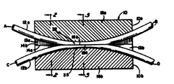
제 1 도 내지 제 4 도에 도시한 바와같이, 본 발명에 사용된 결합기( 10)은 각각의 장방형 기부 또는 블록(16a 및 16b)의 광학적으로 평평한 대향 표면(14a 및 14b)내에 각각 형성된 종방향 아치형 홈(13a 및 13b)내에 장착된 단일 모우드 광학 섬유 물질로 된 2 개의 가닥(12a 및 12b)를 포함한다. 가닥 (12a)가 홈(13a)내에 장착된 블록 (16a)를 결합기 절반부(10a)라고 하고, 가닥(12b)가 홈(13b)내에 장착된 블록(16b)를 결합기 절반부(10b)라고 하겠다.As shown in FIGS. 1-4, the
각각의 가닥(12a 및 12b)는 각각의 중심 코어(19a 및 19b) 및 각각의 외부 피복물(17a 및 17b)를 갖도록 도우프(dope)된 시판중인 석영유리로 된 광학 섬유로 구성된다. 가닥(12a 및 12b)는 전형적으로 10 미크론 이하 정도의 코어 직경 및 125 미크론 정도의 피복물 직경을 갖고 있는 단일 모우드 광학 섬유이다. 도시한 실시예에서, 가닥(12)의 직경 및 각각의 코어는 명확히 도시하기 위해 확대되어 있다.Each strand 12a and 12b consists of commercially available quartz glass optical fibers doped with respective center cores 19a and 19b and respective outer coatings 17a and 17b. Strands 12a and 12b are typically single mode optical fibers having a core diameter on the order of 10 microns or less and a coating diameter on the order of 125 microns. In the illustrated embodiment, the diameter of the strands 12 and each core are enlarged for clarity.
각각의 아치형 홈(13a 및 13b)는 광학 섬유 (12)의 직경에 비해서 매우 큰 곡선 반경을 갖고 있고, 광학섬유(12)가 이 홈속에 장착될 때 홈(13)의 저면벽에 의해 정해진 통로에 일치하게 하기 위해 광학 섬유 직경보다 약간 큰 폭을 갖고 있다. 홈(13a 및 13b)의 깊이는 각각의 블록(16a 및 16b)의 중심부에서의 최소치로부터 각각의 블록(16a 및 16b)의 연부에서의 최대치로 변한다. 이것은, 유리하게도, 광학 섬유 가닥(12a 및 12b)가, 홈(13a 및 13b)내에 장착될 때, 중심부를 향해 점점 모이게 하고 블록(16a 및 16b)의 연부를 향해 분기되게 하므로, 모우드 섭동을 통해 전력 손실을 야기시킬 수 있는 광학 섬유(12)의 방향으로의 뾰족한 만곡 또는 갑작스런 변화들을 제거시킨다. 도시한 실시예에서,홈(13)은 단면이 장방형인 것으로 도시되어 있으나, 광학 섬유(12)를 수용하는 U형 단면이나 V형 단면과 같은 다른 적당한 단면 외형이 선택적으로 사용될 수도 있다.Each arcuate groove 13a and 13b has a very large radius of curvature compared to the diameter of the optical fiber 12, and the passage defined by the bottom wall of the groove 13 when the optical fiber 12 is mounted therein. It has a width slightly larger than the optical fiber diameter in order to coincide with. The depth of the grooves 13a and 13b varies from the minimum at the center of each of the
도시한 실시예에서, 블록(16)의 중심부에서의 가닥(12)를 장착시키는 홈(13)의 깊이는 가닥(12)의 직경보다 작고, 블록(16)의 연부에서의 홈(13)의 깊이는 양호하게도 최소한 가닥(12)의 직경만큼 크다. 광학 섬유 물질은 대향표면(17a 및 17b)와 각각 동일 평면에 각각의 타원형 프래너표면(18a 및 18b)를 형성하도록 각각의 가닥(12a 및 12b)로부터 제거되었다. 이 표면(18a 및 18b)를 본 명세서에서는 광학 섬유"접촉 표면" 이라고 부르겠다. 그러므로, 제거된 광학 섬유 물질의 량은 블락(16)의 연부를 향한 0로부터 블럭(16)의 중심부를 향한 최대치고 점점 증가한다. 광학 섬유 물질의 테이퍼식(tapered)제거는 광학 섬유가 점점 모이고 분기되게 하여, 광선 에너지의 후방 반사 및 과대 손실을 방지하는 데 이롭게 된다.In the illustrated embodiment, the depth of the grooves 13 for mounting the strands 12 at the center of the block 16 is less than the diameter of the strands 12 and the depth of the grooves 13 at the edges of the block 16. The depth is preferably at least as large as the diameter of the strands 12. The optical fiber material was removed from the respective strands 12a and 12b to form respective elliptical
도시한 실시예에서, 결합기 절반부(10a 및 10b)는 동일하고, 블록(16a 및 16b)의 대향 표면(14a 및 14b)를 함께 배치시킴으로써 조립되므로, 가닥(12a 및 12b)의 접촉 표면(18a 및 18b)는 접촉 관계로 있게 된다.In the illustrated embodiment, the coupler halves 10a and 10b are identical and are assembled by placing the opposing
인덱스(index)정합 오일과 같은 인덱스 정합 물질(도시하지 않았음)은 대향 표면(14)들 사이에 제공된다. 이 물질은 피복물의 굴절률과 거의 같은 굴절률을 갖고 있고, 또한 광학적으로 평평한 표면(14)들이 함께 영구적으로 록크(lock)되지 못하게 한다. 이 오일은 모세관 작용에 의해 블록(16)들 사이에 삽입된다.Index matching material (not shown), such as index matching oil, is provided between the opposing surfaces 14. This material has an index of refraction nearly equal to that of the coating and also prevents the optically flat surfaces 14 from permanently locking together. This oil is inserted between the blocks 16 by capillary action.
상호작용 지역(32)는 가닥(12)의 접합부에 형성되어, 광선이 미소 지역 결합에 의해 가닥들 사이로 이송되게 한다. 미소 지역 결합을 적당히 하기 위해, 광학 섬유(12)로부터 제거된 물질의 량은 가닥(12)의 코어부분들 사이의 간격이 선정된 "임계 지역" 내에 있도록 조심스럽게 제어되어야 한다. 미소 지역은 피복물 속으로 연장되고 각각의 코어(15a 및 15b)외측에서 일정 거리로 신속하게 감소한다. 그러므로, 각각의 코어(15a 및 15b)가 다른 코어의 미소 지역내에 배치되게 하기 위해 충분한 물질이 제거되어야 한다. 너무 적은 물질이 제거되면, 코어(15a 및 15b)는 미소 지역이 안내된 모우드의 바람직한 상호 작용을 야기시킬만큼 충분히 밀접하게 되지 못하므로, 불충분한 결합이 생기게 된다. 반대로, 너무 많은 물질이 제거되면, 광학 섬유의 전달 특성이 변경되어, 모우드 섭동으로 인해 광선 에너지가 손실된다. 그러나, 가닥(12a 및 12b)의 코어(15a 및 15b)사이의 간격이 임계 지역내에 있으면, 각각의 가닥은 다른 가닥으로부터 미소 지역 에너지의 상당한 부분을 수용하여, 에너지를 크게 손실하지 않고서 양호한 결합을 하게 된다. 임계 지역은 광학 섬유(12a 및 12b)의 미수 지역(34a 및 34b)가 각각 결합하기에 충분한 세기로 중첩된, 즉 각각의 코어가 다른 코어의 미소 지역내에 있는 지역(33)을 포함하는 것으로 제 5 도에 개략적으로 도시되어 있다. 그러나,이미 기술한 바와같이, 코어(15a 및 15b)가 너무 밀접하게 되면 지역(33)내에 모우드 섭동이 생긴다. 예를들어, 단일 모우드 광학 섬유내의 TE11모우드와 같은 약하게 안내된 모우드의 경우에, 이러한 모우드 섭동은 충분한 물질이 코어들을 노출 시키도록 광학 섬유(12)로부터 제거될 때 생기기 시작한다. 그러므로, 임계 지역은 미소지역(34)가 상당한 모우드 섭동-유발 전력손실이 없이 결합을 시키기에 충분한 세기로 중첩되는 지역으로 정해진다.The interaction zone 32 is formed at the junction of the strands 12 such that light rays are transported between the strands by microregion bonding. In order to moderate the micro area bonding, the amount of material removed from the optical fiber 12 must be carefully controlled such that the spacing between the core portions of the strand 12 is within a predetermined " critical zone ". The micro area extends into the coating and rapidly decreases a certain distance outside each of the cores 15a and 15b. Therefore, enough material must be removed to allow each core 15a and 15b to be placed within the micro area of the other core. If too little material is removed, the cores 15a and 15b will not be close enough to cause the desired interaction of the guided micro-regions, resulting in insufficient bonding. Conversely, if too much material is removed, the transmission properties of the optical fiber change, resulting in loss of light energy due to the mode perturbation. However, if the spacing between the cores 15a and 15b of the strands 12a and 12b is within the critical zone, then each strand receives a significant portion of the micro-regional energy from the other strand, resulting in good bonding without significantly losing energy. Done. The critical zone is defined as comprising an area 33 in which the bare areas 34a and 34b of the optical fibers 12a and 12b are overlapped with sufficient strength, respectively, i.e. each core is within the micro area of the other core. Shown schematically in 5 degrees. However, as already described, mode perturbation occurs in region 33 if the cores 15a and 15b become too close. For example, in the case of a weakly guided mode, such as a TE 11 mode in a single mode optical fiber, this mode perturbation begins to occur when sufficient material is removed from the optical fiber 12 to expose the cores. Therefore, the critical area is defined as the area where the micro area 34 overlaps with sufficient strength to allow coupling without significant mode perturbation-induced power loss.
특정한 결합기에 대해 임계 지역을 연장시키는 것은 광학 섬유 자체의 파라메타와 결합기의 기하학적인 구조와 같은 다수의 상호관련 요인에 좌우된다. 또한, 계단식 인덱스 측면을 갖고 있는 단일 모우드 광학 섬유의 경우에, 임계 지역은 매우 좁게 될 수 있다. 제 1 도 내지 제 4 도에 도시한 형태의 단일 모우드 광학 섬유의 경우에, 예를들어, 결합기의 중심부에서의 가닥(12)들 사이의 필요한 중심-대-중심 간격은 전형적으로 몇 개(예를들어, 2 내지 3개)의 코어 직경이하이다.Extending the critical region for a particular coupler depends on a number of interrelated factors, such as the parameters of the optical fiber itself and the geometry of the coupler. In addition, in the case of single mode optical fibers having a stepped index side, the critical area can be very narrow. In the case of single mode optical fibers of the type shown in FIGS. 1 to 4, for example, the required center-to-center spacing between strands 12 at the center of the coupler is typically several (eg For example, 2 to 3) core diameter or less.
양호하게도, 가다(12a 및 12b)는 (1)서로 동일하고, (2)상호작용 지역(32)에서의 곡선 반경이 동일하며,(3) 각각의 접촉 표면(18a 및 18b)를 형성하도록 이로부터 제거된 광학 섬유 물질의 량이 동일하다. 그러므로, 광학 섬유(12)는 상호작용 지역(32)를 통해 접촉 표면(18)의 평면에 대칭으로 놓이므로, 접촉 표면(18)은 중첩될 경우에 동일하게 연장된다. 이것은 2 개의 광학 섬유(12a 및 12b)가 상호 작용 지역(32)에서 동일한 전달 특성을 갖게 하므로, 상이한 전달 특성에 관련된 결합 감쇠를 방지시킨다.Preferably, the leads 12a and 12b are (1) identical to each other, (2) the radius of curvature at the interaction zone 32 is the same, and (3) to form the
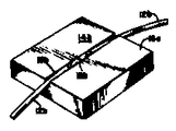
블록 또는 기부(12)는 적당한 강성 물질로 제조될 수 있다. 한 양호한 실시예에서, 기부(12)는 길이가 약 1 인치(2.54㎝)이고, 폭이 1 인치(2.54㎝)이며, 두께가 0.4 인치(약 1.016㎝)인 응용 석영 유리의 장방형 블록으로 구성된다. 이 실시예에서, 광학 섬유 가닥(12)는 에폭시 접착제와 같은 적당한 접착제(38)에 의해 슬롯트(13)내에 고착된다. 용융 석영 블록(16)의 한가지 장점은 이 블록들이 유리 섬유의 열팽창 계수와 유사한 열팽창 계수를 갖고 있다는 것인데, 이 장점은 특히 블록(16) 및 광학 섬유(12)가 제조 공정 중에 열처리를 받을 경우에 중요하다. 블록(16)용의 다른 적당한 물질은 이 응용의 경우에 우수한 열특성을 갖고 있는 실리콘이다.The block or base 12 may be made of a suitable rigid material. In one preferred embodiment, base 12 consists of a rectangular block of applied quartz glass about 1 inch (2.54 cm) long, 1 inch (2.54 cm) wide, and 0.4 inch (about 1.016 cm) thick. do. In this embodiment, the optical fiber strand 12 is secured in the slot 13 by a suitable adhesive 38, such as an epoxy adhesive. One advantage of the fused quartz block 16 is that these blocks have a coefficient of thermal expansion similar to that of glass fibers, especially when the blocks 16 and optical fibers 12 are subjected to heat treatment during the manufacturing process. It is important. Another suitable material for the block 16 is silicon, which has good thermal properties for this application.
[결합기(10)의 동작][Operation of the combiner 10]
결합기(10)은 제 1 도에 A, B, C 및 D로 표시한 4개의 포오트를 포함한다. 제 1 도의 사시도를 고찰하면, 가닥(12a 및 12b)에 각각 대응하는 포오트 A 및 포오트 C는 결합기(10)의 좌측에 있고, 가닥(12a 및 12b)에 각각 대응하는 포오트 B 및 포오트 D는 결합기(10)의 우측에 있다. 설명을 하기 위해서, 입력 광선이 포오트 A로 인가된다고 가정한다. 이 광선은 가닥(12)들 사이에 결합되는 전력량에 따라 결합기를 통과하여 포오트 B 및 포오트 D에서 출력으로 된다. 이에 관련해서, "표준 결합 전력"이란 용어는 결합 전력 대전체 출력 전력의 비로서 정해진다. 상기 예에서, 표준 결합 전력은 포오트 D에서의 전력 대 포오트 B 및 포오트 D에서의 전력 출력의 합계의 비와 동일하게 된다. 이 비는 또한 "결합 효율"이라고도 불리우는데, 이렇게 사용될 때는 전형적으로 %로서 표시된다. 그러므로 "표준 결합 전력"이란 용어가 본 명세서에 사용되면, 대응하는 결합 효율이 표준 결합 전력의 배와 동일하게 된다는 것을 알아야 한다. 이에 관련해서, 검사 결과, 결합기(10)이 100%까지의 결합 효율을 갖는 것으로 나타났다. 그러나, 결합기(10)은 0과 최대치 사이의 바람직한 값으로 결합 효율을 조정하도록 "조정"될 수도 있다는 것도 알 수 있다.
또한, 결합기(10)은 방향성이 높으므로, 결합기의 한측에 인가된 전력은 거의 모두 결합기의 다른 측으로 전달된다. 결합기 방향성은 포오트 A로 입력이 인가될 때, 포오트 D에서의 전력 대 포오트 C에서의 전력의 비로서 정해진다. 검사결과, (포오트 D에서의)방향성 결합 전력은 (포오트 C에서의)역방향성 결합 전력보다 6db 가 더 큰 것으로 나타났다. 또한, 이 결합기 방향성은 대칭이다. 즉, 결합기는 결합기 측이 입력측이거나 출력측이거나 간에 관계없이 동일한 특성으로 동작한다. 또한, 결합기(10)은 매우 낮은 시스템 효율 손실로서 이 결과들을 달성한다. 시스템 효율 손실은 1에서 뺀 전체 출력 전력(포오트 B 및 포오트 D)대 입력 전력(포오트 A)의 비[즉, 1-(PB +PD)/PA]로서 정해진다. 실험결과, 0.5db의 손실이 통상적이었으나, 0.2db의 효율 손실이 얻어진 것으로 나타났다. 또한, 이 실험들은 결합기(10)이 인가된 입력 광선의 편광에 거의 무관하게 동작한다는 것을 나타낸다.Also, since the
결합기(10)은 광선이 가닥(12)들 사이로 이송되도록 가닥(12)의 안내 모우드가 미소 지역들을 통해 상호 작용하는 미소 지역 결합원리로 동작한다. 이미 기술한 바와 같이, 이 광선 이동은 상호 작용 지역(32)에서 생긴다. 이동된 광선의 량은 상호 작용 지역(32)의 유효 길이 뿐만 아니라, 코어(15a 및 15b)의 근접도 및 배향에 따라 변한다. 다음에 상세하게 기술하는 바와 같이, 이송된 광선의 량은 광선의 파장에 따라서도 변한다. 상호 작용 지역(32)의 길이는 광학 섬유(12)의 곡선 반경에 따라 변하고, 코어 간격의 제한 크기에 따라 변하지만, 상호 작용 지역(32)의 유효 길이는 코어 간격에 무관하다. 그러나, 다음에, 더욱 상세하게 기술하는 바와 같이, 결합 길이는 코어간격 뿐만 아니라 파장의 함수이다. 약 1.4 미크론의 연부-대-연부코어 간격 및 25㎝ 정도의 곡선 반경을 사용하는 한 예시적인 실시에서, 유효 상호 작용 지역은 633㎚의 광선 신호 파장에서 길이가 약 1㎜이다. 이러한 결합기내에서, 633㎚에서의 결합 길이가 또한 1㎜이기 때문에, 광선은 상호 작용 지역(32)를 통해 이동할 때 가닥(12)들 사이로 단 한번만 이동하게 된다. 그러나, 상호 작용 지역(32)의 길이가 증가되거나, 코어 간격이 감소되면, 결합 길이가 유효 상호 작용 길이보다 짧기 때문에 본 명세서에서 "과대 결합"이라고 칭한 현상이 생긴다. 이러한 상황에서, 광선은 이 광선이 발생된 가닥으로 다시 이동하게 된다. 상호 작용 길이가 더욱 증가되거나 코어 간격이 더욱 감소되면, 유효 상호 작용 길이는 결합 길이의 더 큰 배수로 되고, 광선은 다른 가닥으로 다시 이동된다. 그러므로, 광선은 지역(32)를 통해 이동할 때 2 개의 가닥(12) 사이에서 앞뒤로 여러번 이동하게 되는데, 이러한 이동 횟수는 상호 작용 지역(32)의 길이, (다음에 기술한 바와 같은)광선 파장 및 코어 간격에 따라 변하게 된다.The
[유효 상호 작용 길이][Effective interaction length]
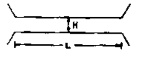
상기 내용을 제 1 도의 결합기(10)을 개략적으로 도시한 제 6 도를 참조하여 더욱 상세하게 기술하겠다. 광학 섬유(12a 및 12b)의 코어들은 결합기의 중심부에서 H로 표시된 최소 간격으로 점점 모이고 결합기의 연부를 향해 분기되는 것으로 도시되어 있다. 유효 상호 작용 길이는 L로 표시되어 있고, 가닥(12a 및 12b)의 곡선 반경은 R로 표시되어 있다. 상술한 바와같이, 유효 상호 작용 길이 L은 곡선 반경 R의 함수로 되지만, 광학 섬유(12)들 사이의 최소 간격 H와는 거의 무관하게 된다. 이 무관성은 비교적 큰 코어 간격과 짧은 파장의 경우에만 유효하게 되지만, 대부분의 경우에 양호한 근사치를 제공하므로, 유리하게도 제 6 도에 도시한 결합기가 제 7 도에 도시한 바와 같이 제 6 도의 간격 H와 동일한 간격 H 만큼 상호 작용 길이 L(제 6 도의 결합기의 유효 상호 작용 길이 L과 동일함)을 통해 분리된 2 개의 평행한 도파관을 포함한 "등가" 결합기로서 분석될 수 있게 된다.This will be described in more detail with reference to FIG. 6, which schematically shows the
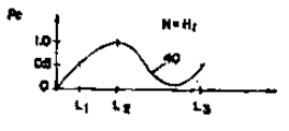
제 7 도에 도시한 "등가" 결합기의 유효 상호 작용 길이 L 또는 광학 섬유 간격 H를 변화시키는 효과는 제 8 도 및 제 9 도를 참조함으로써 알수가 있다. 제 8 도는 결합 전력 P0가 소정의 광학 섬유 간격 H1 및 소정의 파장에 대한 상호 작용 길이 L의 함수로서 정현파 형태로 변하는 것을 나타내는 정현파 곡선(40)을 도시한 것이다. 이 광학 섬유 간격에서, 결합 전력은 상호 작용 길이가 L1일 때 약 50% 이고, 상호 작용 길이가 L2로 증가할 때 100%로 증가된다. 상술한 정의에 따르면, L2는 이 소정의 파장에 대한 결합 길이와 같다. 상호 작용 길이가 더욱 증가되어 결합 길이보다 더 길어지면, "과대 결합"이 생기어, 광선은 이 광선이 발생된 가닥으로 다시 이동되고, 결합 전력 P0는 0을 향해 감소하기 시작한다. 그 다음, 결합 전력은 L3에서 0으로부터 예를 들어 50%로 증가한다. 그러므로, 결합량은 제 7 도의 "등가 결합기"의 상호 작용 지역의 길이 L을 변화시킴으로써 변화될 수 있다.The effect of changing the effective interaction length L or the optical fiber spacing H of the "equivalent" coupler shown in FIG. 7 can be seen by referring to FIGS. 8 and 9. FIG. 8 shows a sinusoidal curve 40 showing that the coupling power P0 changes in sinusoidal form as a function of a given optical fiber spacing H1 and an interaction length L for a given wavelength. At this optical fiber spacing, the bonding power is about 50% when the interaction length is L1 and increases to 100% when the interaction length increases to L2. According to the above definition, L2 is equal to the bond length for this predetermined wavelength. As the interaction length is further increased and longer than the bond length, "overcombination" occurs, the light beam is moved back to the strand where it was generated, and the bond power P0 begins to decrease towards zero. The combined power then increases from zero at L3, for example 50%. Therefore, the binding amount can be changed by changing the length L of the interaction zone of the "equivalent coupler" of FIG.
이 "등가 결합기"의 광학 섬유들 사이의 간격 H를 감소시킴으로써, 결합 세기가 증가되어, 제 8 도의 정현파 곡선과 제 9 도의 정현파 곡선(42)를 비교함으로써 알 수 있는 바와 같이, 소정의 상호 작용 길이 L을 통해 이동되는 광선량이 증가된다. 예를 들어, 광학 섬유 간격이 H1(제 8 도)에서 H2(제 9 도)로 감소되면, 결합 전력은 제 8 도 내의 동일한 상호 작용 길이 L1의 50%에 비교된 바와 같이, 제 9 도 내의 상호 작용길이 L1에서 100%로 될 수 있다. 그러므로, 이 간격 변화는 소정의 파장에 대한 결합 길이를 효율적으로 L2(제 8 도)에서 L1(제 9 도)로 감소시킨다. 그 다음, 곡선(42)는 과대 결합을 나타내기 시작하고 결합 전력은 상호 작용 길이 L2에서 50%로 감소된다. 결합 길이 L1의 홀수배(5배)인 상호 작용 길이 L3에서, 곡선(42)는 결합 전력이 다시 100%로 된 것을 나타낸다. 그러므로, 제 7 도의 "등가 결합기"내의 소정의 상호 작용 길이(예를 들어, L1, L2 또는 L3) 및 광선 파장의 경우에, 결합 길이는 광학 섬유 코어 간격을 변화 시킴으로써 조정될 수 있다.By reducing the spacing H between the optical fibers of this "equivalent coupler", the bond strength is increased, as can be seen by comparing the sinusoidal curve of FIG. 8 and the sinusoidal curve 42 of FIG. The amount of light traveled through the length L is increased. For example, if the optical fiber spacing is reduced from H1 (FIG. 8) to H2 (FIG. 9), the coupling power is in FIG. 9 as compared to 50% of the same interaction length L1 in FIG. 8. Interaction length can be 100% at L1. Therefore, this spacing change effectively reduces the bond length for a given wavelength from L2 (Figure 8) to L1 (Figure 9). The curve 42 then begins to show an overcoupling and the coupling power is reduced to 50% at the interaction length L2. At interaction length L3, which is an odd multiple (5 times) of the bond length L1, the curve 42 indicates that the bond power is again 100%. Therefore, in the case of the desired interaction length (e.g., L1, L2 or L3) and light wavelength in the "equivalent coupler" of FIG. 7, the bond length can be adjusted by varying the optical fiber core spacing.
제 7 도의 "등가 결합기"의 소정의 상호 작용 길이 L 및 소정의 광선 파장에 대한 최소 광학 섬유 간격 H와 결합 전력 P0 사이의 관계는 제 10 도에 곡선(44)로 도시되어 있다. 이 도면에 도시한 바와 같이, 표준 결합 전력은 0 과 1 사이로 진동하는데, 코어 간격 H를 감소시킴으로써 결합 길이가 감소될 때 주파수가 증가된다. 곡선 H상의 기준점 a, b 및 c는 0.5, 1.0 및 0.25 의 표준 결합 전력을 각각 나타내도록 다소 임의로 선택되었다. 지점 "a"에서, 전력의 50%는 한 광학 섬유로부터 다른 광학 섬유로 결합된다. 지점 "b"에서는 완전 결합이 이루어져, 광학 전력의 100%가 가닥들 사이로 이동된다. 한편, 지점 "c"는 결합 전력이 완전 결합으로부터 25%로 감소된 과대결합 상태를 나타낸다.The relationship between the predetermined interaction length L of the “equivalent coupler” of FIG. 7 and the minimum optical fiber spacing H and the coupling power P0 for a given light wavelength is shown by curve 44 in FIG. 10. As shown in this figure, the standard coupling power oscillates between 0 and 1, which increases in frequency when the coupling length is reduced by reducing the core spacing H. Reference points a, b and c on curve H were chosen somewhat randomly to represent standard binding powers of 0.5, 1.0 and 0.25, respectively. At point "a", 50% of the power is combined from one optical fiber to another. At point "b" a full bond is made, whereby 100% of the optical power is transferred between the strands. Point “c”, on the other hand, represents an overcoupled state in which the combined power is reduced from full bond to 25%.
전술한 바와같이, 제 6 도에 개략적으로 도시한 결합기의 상호 작용 길이는 제 7 도에 도시한 "등가 결합기"를 사용함으로써 가장 유리하게 분석되는데, 이 도면에서 최소 간격 H는 실제광학 섬유의 최소 간격 H와 동일하지만, 제 6 도의 실제 광학 섬유의 최소 간격 H와 동일하지만, 제 6 도의 실제 광학 섬유의 "유효 상호 작용 길이"는 제 7 도의 "등가 결합기"의 실제 상호 작용 길이와 동일하다. 이 분석시에, 제 6 도의 결합기의 "유효 상호 작용 길이"는 주로 실제 결합기의 곡선 반격 R에 따라 변하는 복소 함수이다. 이 분석은 광학 섬유의 축 방향에 있는 최소 간격의 지점으로부터 양 방향의 결합 계수를 적분하는 것을 포함하는데, 결합 계수는 광학 섬유의 변화 간격에 따라 변한다. 중첩된 구부러진 광학 섬유에 대한 이 변화 간격은, R이 최소 간격 지점으로부터의 광학 섬유의 곡선 반경이고 H0 가 최소 간격 거리인 경우, 식 H(Z) = HO+Z2/2R로 된다.As mentioned above, the interaction length of the coupler shown schematically in FIG. 6 is most advantageously analyzed by using the "equivalent coupler" shown in FIG. 7, where the minimum spacing H is the minimum of the actual optical fibers. Same as the spacing H, but equal to the minimum spacing H of the actual optical fiber of FIG. 6, but the "effective interaction length" of the real optical fiber of FIG. 6 is the same as the actual interaction length of the "equivalent coupler" of FIG. In this analysis, the "effective interaction length" of the coupler of FIG. 6 is primarily a complex function that varies with the curve counterpart R of the actual coupler. This analysis involves integrating the binding coefficients in both directions from the point of the minimum spacing in the axial direction of the optical fiber, the binding coefficients varying with the change interval of the optical fiber. The variation interval of the superimposed optical fiber is bent, R the curve radius of the optical fibers from the minimum distance point, and if H0 is the minimum gap distance is in equation H (Z) = H O + Z 2 / 2R.
이 분석으로부터, 결합기 "유효 상호 작용 길이"아 광학 섬유 곡선 반경 R과의 전형적인 의존 관계는 광범위한 신호 파장의 경우에 대해 제 11 도에 도시되어 있다. 예상한 바와 같이, 상호 작용 길이는 곡선 반경이 증가함에 따라 증가한다. 근사적으로, 최소 광학 섬유 간격 H0 가 광학 섬유 반경 a와 비교해 볼 때 큰 경우 및 값 V(신호 주파수), 즉 짧은 신호 파장이 큰 경우, 상호 작용 길이 값 L은 다음과 같이 된다.From this analysis, the typical dependence of the coupler "effective interaction length" and the optical fiber curve radius R is shown in Figure 11 for the case of a wide range of signal wavelengths. As expected, the interaction length increases with increasing curve radius. Approximately, when the minimum optical fiber spacing H0 is large compared to the optical fiber radius a and the value V (signal frequency), i.e., the short signal wavelength is large, the interaction length value L becomes as follows.
L = (R)1/2(V/∏ a+1/4H0)-1/2 L = (R) 1/2 (V / ∏ a + 1 / 4H 0 ) -1/2
이 식으로부터, 상호 작용 길이 L은 (R)1/2로 증가된다는 것을 알 수 있다. 이 결과는 제 11 도에 도시되어 있다. 계수 4 만큼 반경 R이 증가하면 유효 상호 작용 길이가 2배로 늘어난다.From this equation, it can be seen that the interaction length L is increased to (R) 1/2 . This result is shown in FIG. Increasing the radius R by a factor of 4 doubles the effective interaction length.
상술한 바와 같이, 유효 상호 작용 길이 L은 제 6 도의 최소 광학 섬유 간격 H와 무관한 것으로서 생각 할 수 있다.As mentioned above, the effective interaction length L can be thought of as being independent of the minimum optical fiber spacing H of FIG.
멀티플렉서로서 이 결합기를 사용하 때에는, 상기 L에 대한 근사식에 의해 기술된, 유효 상호 작용 길이 L(제 6 도)와 신호 파장과의 의존 관계가 중요하다. 값 γ가 광학 섬유 피복물 내부의 비-섭동 광학 섬유 모우드의 미소 지역의 투과 깊이인 경우에, γ=v/a로 된다. 상호 작용 길이에 대한 상기식은 긴 신호 파장이 광학 섬유 피복물 내로 더 깊이 투과하기 때문에 이 길이가 파장에 따라 증가한다는 것을 나타낸다.When using this coupler as a multiplexer, the dependence of the effective interaction length L (figure 6) and the signal wavelength, as described by the approximation to L above, is important. When the value γ is the transmission depth of the micro area of the non-perturbed optical fiber mode inside the optical fiber coating, γ = v / a. The above equation for interaction length indicates that this length increases with wavelength because long signal wavelengths penetrate deeper into the optical fiber coating.
유효 상호 작용 길이(제 6 도)에 대한 신호 파장의 효과는 제 12 도에 도시되어 있다. 이 도면에서, 상호 작용 길이는 파장이 증가함에 따라 다소 선형으로 증가한다.The effect of the signal wavelength on the effective interaction length (Figure 6) is shown in Figure 12. In this figure, the interaction length increases somewhat linearly with increasing wavelength.
상술한 개념은 결합기(10)의 "동조능력" 개념을 이해하는 데 유용하다. 본 명세서에 사용한 바와같이, "동조"란 용어는 광학 섬유들 사이에 결합된 전력을 조정하기 위해 서로 관련해서 광학 섬유(12)를 이동시키는 것을 뜻한다. 광학 섬유(12)의 이러한 이동은 서로 관련해서 프래너 접촉 표면(18)을 미끄러트림으로써 이루어지므로, 광학 섬유들은 중첩되지 않고, 편기된다. 즉, 광학 섬유(12)는 프래너 접촉 표면의 평면내에서 서로 이동된다. 다른 관점에서 보면, 이러한 이동은 각각의 광학 섬유가 놓이는 각각의 평면이 서로 관련하여 이동될 때 생긴다.The above-described concepts are useful for understanding the concept of "tuning capability" of the
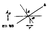
광학 섬유 이동의 한 양호한 방법에서, 접촉 표면(18)은 측방향으로 편기된다. 본 명세서에 사용한 바와 같이, "측방향 편기"란 용어는 광학 섬유(12)들 사이의 병렬 관계를 계속 유지하면서 광학 섬유 코어들 사이의 간격을 증가시키기 위해 중첩 위치로부터 접촉 표면(18)을 측방향으로 미끄러트리는 것을 뜻한다. 접촉 표면(18)의 이러한 측방향 편기는 제 13 도에 개략적으로 도시되어 있다. 물론, 이러한 측방향 편기의 효과는 광학 섬유(12)의 코어들 사이의 간격을 변화시키는 것이다. 그러나, 이 간격 변화외에도, 상호 작용 길이도 영향을 받는다. 식 H(Z) = H0+Z2/2R은 중첩된 구부러진 광학 섬유 대한 변화 간격의 정의로서 제공되었다. 이러한 광학 섬유가 측방향으로 편기되면, 이식은 더욱 복잡해진다. 제 14 도 및 제 15 도는 이미 분석한 중첩된 형태에 대한 2 개의 개념(광학 섬유 평면에 대한 평행 및 수직 개념)을 간략하게 도시한 것이다. 제 16 도 및 제 17 도에 도시한 편기 형태에서, Y가 측방향 편기이면 최소 광학 섬유 간격은 (HO 2+Y2)1/2로 되지만, 제 17 도에 점선으로 표시한 이 최소 간격의 방향은 광학 섬유의 평면내에 더 이상 놓치지 않게 된다. 제 17 도에 도시한 새로운 축△는 평면에 대하여 비뚤어진다. 이 △축 방향으로부터 바라보면, 광학 섬유 곡선이 변하고, 곡선의 투영된 반경은 실제 반경 R보다 더 크게 된다. 그러므로, 광학 섬유들 사이의 간격 H(Z)는 두 형태가 동일한 최소 간격을 갖고 있을 때 중첩된 형태에서만큼 빠르게 Z축을 따라 증가하지 못한다. 그러므로, 이 편기 형태에서의 H(Z)에 대한 상기 식은 H(Z) = [(HO+Z2/R)2+Y2]1/2로 된다.In one preferred method of optical fiber movement, the
이 예상된 동작은 결합기 상호 작용 길이 대 광학 섬유 편기 Y를 계산함으로서 직접 증명 될 수 있다. 제 18 도는 광학 섬유 편기가 증가함에 따라 결합기 상호 작용 길이가 증가하는 상태를 도시한 것이다.This expected behavior can be demonstrated directly by calculating the length of the coupler interaction versus the optical fiber knitting machine Y. 18 illustrates a state in which the length of the coupler interaction increases as the optical fiber knitting is increased.
상술한 설명으로부터, 소정의 신호 파장에서 유효 상호 작용 길이 L(제 6 도)은 주로 광학 섬유의 곡선 반경에 따라 변한다는 것을 알 수 있다. 최소 광학 섬유 간격 H와의 의존성은 모든 실제목적들을 위해 무시될 수 있다. 다른 파장을 갖고 있는 신호들이 피복물내로의 다른 투과 깊이를 갖고 있으므로, 시호 파장에 따라 상호 작용 길이가 변하게 된다. 즉, 상호 작용 길이는 파장이 증가함에 따라 증가된다. 부수적으로 구부러진 광학 섬유 결합기의 기하학적 형태는 각각의 광학 섬유의 유효 곡선 반경이 증가된다. 부수적으로 구부러진 광학 섬유 결합기의 기하학적 형태는 각각의 광학 섬유의 유효 곡선 반경이 증가하게 하여, 광학 섬유의 측방향 편기가 증가함에 따라 상호 작용 길이를 증가시킨다. 이 설명으로부터의 중요한 결론은, 소정의 광학 섬유 형태 및 신호 파장의 경웨, 중첩된 형태의 제 6 도의 구부러진 광학 섬유들 사이의 유효 상호 작용 길이가 광학 섬유 곡선 반격 R을 선택함으로써 제조시에 셋트된다는 것이다.From the above description, it can be seen that at a given signal wavelength, the effective interaction length L (FIG. 6) varies mainly with the radius of curvature of the optical fiber. The dependency on the minimum optical fiber spacing H can be neglected for all practical purposes. Since signals with different wavelengths have different transmission depths into the coating, the interaction length varies with the signal wavelength. That is, the interaction length increases with increasing wavelength. Incidentally, the bent geometry of the optical fiber coupler increases the effective curve radius of each optical fiber. Incidentally bent geometry of the optical fiber coupler causes the effective curve radius of each optical fiber to increase, increasing the interaction length as the lateral knitting of the optical fiber increases. An important conclusion from this description is that the effective interaction length between the bent optical fibers of Fig. 6 in the superimposed form, at the given optical fiber shape and signal wavelength, is set at the time of manufacture by selecting the optical fiber curve counterpart R. will be.
제 19 도의 곡선(46)은 "a"(제 10 도)와 동일한 최소 연부-대-연부 코어 간격 H와 소정의 파장 광선을 갖고 있는 결합기에 대한 광학 섬유 접촉 표면(18)의 측방향 편기 효과를 그래프로 도시한 것이다. 광학 섬유의 접촉 표면(18)이 중첩되면(즉, 편기가 없으면), 표준 결합 전력은 제 10 도의 곡선(44)에 의해 요구된 바와 같이 0.5로 된다. 그러나, 광학 섬유(12)의 접촉 표면(18)이 코어들 사이의 간격을 증가시키도록 어느 한 방향으로 측방향 편기되면, 결합 전력은 점차 0으로 감소한다.Curve 46 in FIG. 19 shows the lateral knitting effect of the optical
제 20 도의 곡선(48)을 참조하면, "b"(제 10 도)와 동일한 연부-대-연부 코어 간격과 동일한 광선 파장을 갖고 있는 결합기에 대한 표준 결합 전력에 따른 측방향 광학 섬유 편기 효과가 도시되어 있다. 편기가 없고 접촉 표면(18)들이 중첩될 때, 표준 결합 전력은 제 10 도의 곡선(44)에 의해 요구된 바와같이 1.0 이지만, 광학 섬유(12)의 접촉 표면(18)이 어느 한 방향으로 측방향 편기돌 때 결합 전력은 점차로 감소한다.Referring to curve 48 of FIG. 20, the effect of lateral optical fiber knitting is dependent on the standard coupling power for a coupler having the same ray-to-edge core spacing as the "b" (figure 10). Is shown. When there is no knitting and the contact surfaces 18 overlap, the standard coupling power is 1.0 as required by curve 44 of FIG. 10, but the
제 21 도의 곡선(50)은 "c"(제 10 도)와 동일한 코어 간격과 동일한 광선 파장에 대한 관련된 광학 섬유 편기함수로서 결합 전력을 나타내는데, 이 곡선은 과대 결합 상태를 나타낸다(즉, 유효 상호 작용 길이는 결합 길이를 초과한다). 이 곡선(50)으로부터의, 광학 섬유(12)의 접촉 표면(18)들이 중첩되면, 표준 결합 전력이 0.25로 된다는 것을 알수 있다. 코어 간격은 접촉 표면(18)을 측방향으로 편기되도록 미끄러트림으로써 증가되므로, 표준 결합 전력은 처음에 유효 상호 작용 길이가 결합 길이와 동일하도록 감소될 때 1.0으로 증가하고, 그 다음 코어 간격이 더욱 증가될 때 0을 향해 감소한다.Curve 50 in FIG. 21 represents the coupling power as the associated optical fiber knitting function for the same core spacing and the same light wavelength as "c" (FIG. 10), which represents an overcoupling state (i.e., an effective mutual The length of action exceeds the length of the bond). It can be seen from this curve 50 that if the contact surfaces 18 of the optical fiber 12 overlap, the standard coupling power is 0.25. Since the core spacing is increased by sliding the
제 19 도, 제 20 도 및 제 21 도에 도시된 모든 상술한 경우에 있어서, 이 도면들에 대응하는 물리적 파라메타와 광선 파장이 0 편기에서의 광학 섬유 간격을 제외하면 동일하다고 가정하면, 결합 전력은 동일한 측방향 편기에서 0으로 감소한다. 제 19 도, 제 20 도 및 제 21 도의 곡선(46, 48 및 50)을 각각 비교함으로써, 이 곡선들의 각각의 기울기는 코어 간격이 감소할 때 증가한다는 것을 알 수 있다. 그러므로, 측방향 편기에 대한 결합기의 감도는 제 19도 또는 제 20 도에 도시한 특성을 가진 결합기 보다는 제 21 도에 도시한 특성을 가진 결합기의 경우에 더 높게 된다.In all the above-described cases shown in FIGS. 19, 20 and 21, assuming that the physical parameters and light wavelengths corresponding to these figures are the same except for the optical fiber spacing in the zero knitting machine, the combined power Decreases to zero in the same lateral knitting. By comparing the curves 46, 48, and 50 of FIGS. 19, 20, and 21, respectively, it can be seen that the slope of each of these curves increases as the core spacing decreases. Therefore, the sensitivity of the coupler to the lateral knitting machine is higher in the case of the coupler having the characteristics shown in FIG. 21 than the coupler having the characteristics shown in FIGS.
[시스템 효율 손실][System efficiency loss]
실험결과, 결합기(10)의 시스템 효율 손실은 코어의 측방향 편기가 비교적 클때를 제외하면, 거의 일정하였다. 한 예시적인 결합기 상에서의 검사는 시스템 효율 손실이 어느 한 방향으로 10 미크론까지 측방향 편기될 경우, 0.2db로 최소 손실되었다는 것을 나타냈다. 이 결합기는 1.460의 코어 인덱스, 1.4559의 피복물 인덱스 및 4 미크론의 코어 직경을 갖고 있는 단일 모우드 광학 섬유를 사용하였다. 광학 섬유의 곡선 반경은 25㎝이고, 연부-대-연부 코어 간격은 약 0.9 미크론이었으며, 사용된 광선의 파장은 632.8㎚이었다. 제 22 도는 이 예시적인 결합기의 경우의, 접촉표면(18)의 측방향 편기의 함수로서, 참조 번호(60)으로 표시된 시스템 효율 손실의 그래프와 참조번호(62)로 표시된 표준 결합 전력의 그래프를 도시한 것이다. 제 14 도의 중심부를 통해 그어진 2개의 수평파선은 0.2db 전력 손실 대역의 상부 및 하부 영역을 제공한다. 전력 손실 곡선(60)은, 어느한 방향으로 약 12 미크론까지 측방향 편기될 경우, 이 대역내에 있다는 것을 알 수 있다. 또한, 12 미트론 측방향 편기때에, 표준 결합 전력은 약 0.1 이라는 것도 알 수 있다. 그러므로, 결합 전력이 0.1 및 1 인 경우, 전력 손실은 약 0.2db의 최소 전력 손실로 있게 된다. 전력 손실 대역이 0.5db로 확장되면, 전력 손실 대역은 15 미크론 까지의 광학 섬유 편기의 경우에, 0.5dB 대역내에 있게 되는데, 이것은 0.05(즉, 5%) 이하의 결합 전력에 대응한다. 그러므로, 이 결합기는 장치의 전체 동작 범위에 걸쳐서 거의 일정한 시스템 효율 손실, 즉 비교적 좁은 전력 손실 대역폭을 나타낸다. 또한, 시스템 효율 손실은 매우 낮고, 10%와 100% 사이의 결합 전력의 경우에는, 비교적 일정하다.As a result, the system efficiency loss of the
검사 결과, 상술한 예시적인 예어서와 같이, 0.5dB의 손실이 통상적이지만, 약 0.2dB 정도로 낮은 시스템 효율 손실이 얻어진다는 것을 나타냈다.Inspections indicated that, as with the illustrative example described above, a loss of 0.5 dB is typical, but a system efficiency loss as low as about 0.2 dB is obtained.
결합 손실이 결합 효율의 전체 범위에 걸쳐서 접촉 표면(18)의 측방향 편기에 비교적 둔감하기 때문에, 이러한 측방향 편기는 바람직한 결합 전력량을 제공하도록 결합기(10)을 동조시키기에 특히 유리한 방법이다. 그러나, 결합기 특성은 접촉 표면을 종방향 편기 시킴으로써 변화될 수 있다. 이 의미로 사용된 바와 같은 "종방향 편기"란 용어는 제 23 도에 개략적으로 도시한 바와 같이, 광학 섬유(12)와 평행 방향으로 중첩 위치로부터 편기 위치로 접촉표면(18)을 이동시키는 것을 뜻한다. 사실상, 이러한 종방향 편기는 광학 섬유(12)의 최소 코어 간격을 증가시킨다. 예를 들어, 제 10 도를 다시 참조하면, 접촉 표면(18)들이 중첩될 때 광학 섬유 간격 H가 "a"와 같을 때, 접촉 표면(18)을 종방향 편기시키면 이 지점 "a"는 곡선(44)를 따라 "a"라 칭한 지점으로 이동하게 된다. 이와 마찬가지로, 이 종방향 편기는 "b"를 곡선(44)를 따라 "b"로 이동시키고 지점 "C"를 곡선(44)를 따라 "C"로 이동 시킨다. 물론, 이것은 표준 결합 전력을 0 편기로 감소 시킴으로써, 제 19 도, 제 20 도 및 제 21 도의 편기 곡선을 대응하게 변화시킨다.Since the coupling loss is relatively insensitive to the lateral knitting of the
실험결과, 비교적 작은 측방향 편기에 의해 이루어진 변화와 등가인 결합 변화를 발생시키기 위해 비교적 큰 종방향 편기가 필요한 것으로 나타났다. 그러므로, 결합기는 종방향 편기에 비교적 둔감하다. 부수적으로, 시스템 효율 손실이 종방향 편기에 의해 크게 영향을 받지 않기 때문에, 접촉 표면(18)의 배열은 제한되지 않는다.Experimental results have shown that a relatively large longitudinal knitting machine is required to produce a bond change that is equivalent to a change made by a relatively small lateral knitting machine. Therefore, the coupler is relatively insensitive to the longitudinal knitting. Incidentally, since the system efficiency loss is not greatly affected by the longitudinal knitting, the arrangement of the
결합기(10)의 결합 특성은 상호 작용 지역의 유효 길이를 감소시키기 때문에, 서로 관련해서 접촉 표면(18)을 회전시킴으로써 악영향을 받을 수 있다. "회전 편기"란 용어는 공동축, 예를 들어 축(66) 주위에서 접촉 표면(18)을 회전시킴으로써, 제 24 도에 개략적으로 도시한 바와 같이, 광학 섬유를 이동시키는 것을 뜻한다. 이러한 회전 편기의 효과는 표면을 종방향 편기시키기 위한 상술한 효과와 유사하다. 즉, 결합기(10)은 결합 전력 뿐만 아니라 시스템 효율 손실의 변화 면에서 작은 회전 편기에 비교적 둔감하다.Because the coupling properties of the
그러므로, 접촉 표면을 회전 편기시키거나 종방향 편기시킴으로써 결합 전력을 소수 조정할 수 있고, 결합 전력의 주요 조정은 전형적으로 접촉 표면(18)을 측방향 편기시킴으로써 행해지지만, 이 기술들을 결합해서 사용할 수도 있다.Therefore, the coupling power can be minorly adjusted by rotating or longitudinally knitting the contact surface, and the main adjustment of the coupling power is typically done by laterally knitting the
[결합 길이][Coupling length]
상술한 바와 같이, 결합기(10)내의 결합 길이(35)는 소정 파장이 광선을 한 광학 섬유(12)로부터 다른 광학 섬유(12)로 완전히 이동시키는데 필요한 길이이다. 특히 제 8 도, 제 9 도 및 제 10 도를 참조하여 기술한 바와 같이, 결합 길이(35)는 최소 광학 섬유 간격 H (제 6 도)에 의해 직접적으로 악영향을 받는다. 부수적으로, 결합 길이(35)는 광선 파장의 함수이다. 상술한 바와 같이, 광학 섬유 피복물 내부의 비-섭동 광학 섬유 모우드이 미소 지역의 투과 깊이는 파장이 증가함에 따라 증가한다.As discussed above, the
이 현상은 각각의 2 개의 밀접하게 간격을 두고 떨어진 광학 섬유에 대한 미소 지역 크기를 도시한 제 25 도, 제 26 도 및 제 27 도에 그래프로 도시되어 있다. 제 25 도에 도시한 바와 같이, 단파장에서는, 이러한 파장들에서의 미소 지역이 광학 섬유 코어 부근(파선으로 표시함)에 대부분 제한되므로, 즉 모우드들이 각각의 도파관내에 양호하게 안내되고 양호하게 제한되므로, 미소 지역(E1 및 E2) 사이에 불충분한 중첩이 존재한다. 제 26 도에 도시한 바와 같이, 신호 파장이 증가되면, 미소 지역(E1 및 E2)는 광학 섬유 코어로부터 떨어져 더욱 연장되고, 모우드 중첩은 증가한다. 결합 계수는 광학 섬유의 코어(제 25 도 내지 제 27 도의 교차 부분)을 통해 미소 지역 값(E1 및 E2)를 적분한 결과이기 때문에, 이 결합 계수도 마찬가지로 증가한다. 그러나, 제 27 도에 도시한 바와 같이, 장파장인 경우, 모우드들은 대부분의 이용가능한 모우드 에너지가 상호 작용의 교차 영역(광학 섬유 코어)에 없는 주위 피복물 내로 멀리 늘어난다.This phenomenon is graphically shown in FIGS. 25, 26 and 27 showing the micro area size for each of two closely spaced optical fibers. As shown in FIG. 25, in the short wavelength, since the minute region at these wavelengths is mostly limited to the vicinity of the optical fiber core (indicated by the broken line), that is, the modes are well guided and well limited in each waveguide. Insufficient overlap exists between the minute regions E1 and E2. As shown in FIG. 26, as the signal wavelength is increased, the minute regions E1 and E2 extend further away from the optical fiber core, and the mode overlap increases. Since the coupling coefficient is a result of integrating the minute area values E1 and E2 through the core of the optical fiber (cross section of FIGS. 25 to 27), this coupling coefficient is also increased. However, as shown in FIG. 27, in the long wavelength mode, the modes extend far into the surrounding coating where most of the available mode energy is not in the intersecting area of the interaction (optical fiber core).
이 현상은 또한, 피복물(또는 코어)에 의해 이동된 표준 전력과 코어-피복물 공유 영역에서의 전력 밀도가 약하게 안내된 광학 섬유에 대한 표준 주파수의 함수로서 도시된 제 28 도에 도시되어 있다. 더 긴 파장(저 주파수)에서, 대부분의 모우드는 광학 섬유 피복물내에 있게 된다(약하게 안내된다). 코어-피복물 경계 영역, 또는 피복물내의 소정 방사 위치에서의 전력 밀도( 및 전계의 크기)는 소정 신호 파장의 경우에 최대로 된다. 더 짧은 파장에서, 에너지 분포는 코어를 향해 전이되고(양호하게 안내된 모우드), 더 긴 파장에서, 에너지는 더욱 확산되므로, 코어내의 소정 방사 위치에서 감소되지만 (양호하게 안내된 모우드), 더긴 파장에서, 에너지는 더욱 확산되므로 코어 또는 피복물내의 소정 방사위치에서 감소 된다(느슨하게 안내 된다). 병렬 광학 섬유 결합기 내에 최대 결합 파장이 존재하면 모델 전력 밀도 곡선내에 이 최대치가 생기게 된다.This phenomenon is also shown in FIG. 28 where the standard power moved by the coating (or core) and the power density in the core-coating shared area are shown as a function of the standard frequency for the weakly guided optical fiber. At longer wavelengths (low frequencies), most of the mode is in the optical fiber coating (weakly guided). The power density (and magnitude of the electric field) at the core-cover boundary region, or at a predetermined radiation location within the coating, is maximized in the case of a predetermined signal wavelength. At shorter wavelengths, the energy distribution shifts towards the core (goodly guided mode), and at longer wavelengths, the energy is more diffused, so it is reduced at some radiation location within the core (goodly guided mode), but longer wavelengths. In this case, the energy is further diffused and thus reduced (loosely guided) at a given spinning position in the core or coating. The presence of the maximum coupling wavelength in the parallel fiber coupler results in this maximum in the model power density curve.
모우드 중첩은 최대 결합 파장에서 최대로 되기 때문에, 결합 길이(광학 섬유들 사이에서 에너지가 완전히 이동하는 데 필요한 길이)는, 소정의 광학 섬유 간격 H의 경우, 이 최대 결합 파장에서 최소로 나타난다. 또한, 최적한 결합 또는 가장 짧은 결합길이의 파장은 광학 섬유 간격이 증가될 때 적외선을 향해 전이 된다.Since the mode overlap is maximized at the maximum bond wavelength, the bond length (the length required for the full transfer of energy between the optical fibers) is minimal at this maximum bond wavelength, for a given optical fiber spacing H. In addition, the wavelength of the optimal bond or the shortest bond length is shifted towards the infrared rays as the optical fiber spacing increases.
신호 파장과의 결합 길이의 의존 관계는 제 29 도 및 제 30 도에 2 개의 상이한 형태의 광학 섬유에 대해 도시되어 있다. 제 29 도에 도시한 제 1 형태의 광학 섬유는 2 미크론의 광학 섬유 반경, 1.460의 코어 굴절률 및 14599의 피복물 굴절귤을 갖고 있다. 제 30 도에 도시한 제 2 형태의 광학 섬유는 3 미크론의 코어 반경, 1,458의 코어 굴절률 및 1.14551의 피복물 굴절률을 갖고 있다. 이 도면들로부터, 소정의 광학 섬유 간격 H의 경우에, 결합 길이는 처음에 신호 파장이 적외선을 향해 가시 스펙트럼의 한 단부로부터 증가할 때 감소되고, 그 다음 파장이 더욱 증가할 때 증가한다는 것을 알 수 있다. 그러므로, 소정의 광학 섬유 간격의 경우에는, 가장 짧은 결합 길이를 갖고 있는 파장이 있는데, 이 파장은 광학 섬유 간격이 증가할 때 적외선을 향해 전이된다.The dependence of the bond length with the signal wavelength is shown for two different types of optical fibers in FIGS. 29 and 30. The optical fiber of the first aspect shown in FIG. 29 has an optical fiber radius of 2 microns, a core refractive index of 1.460, and a coating refractive orange of 14599. The optical fiber of the second aspect shown in FIG. 30 has a core radius of 3 microns, a core refractive index of 1,458, and a coating refractive index of 1.14551. From these figures, it can be seen that in the case of a given optical fiber spacing H, the bond length initially decreases as the signal wavelength increases from one end of the visible spectrum towards infrared, then increases as the wavelength further increases. Can be. Therefore, in the case of a given optical fiber spacing, there is a wavelength having the shortest bond length, which wavelength is shifted toward the infrared when the optical fiber spacing increases.
[파장 멀티플렉싱][Wavelength multiplexing]
제 1 도 내지 제 4 도를 참조하여 기술한 바와 같이, 단일 모우드 광학섬유 결합기내의 결합 길이가 제 29 도 및 제 30 도에 도시한 바와 같이, 신호파장과 강력한 의존관계에 있기 때문에, 제 2 신호 파장이 기본적으로 비결합된 상태로 유지되는 동안 1 개의 신호 파장을 완전히 결합시키도록 결하기(10)에 대한 기하학적 파라메타들을 양호하게 선택할 수 있다. 이 현상은 2 개의 중첩된 신호들이 결합기의 단일 포오트 내로 분리되어 공급되게 하거나, 2 개의 신호들이 결합기(10)의 한 측상의 포오트내로 결합되어 공급되게 한다. 그러므로, 제 31 도에 도시한 바와같이, 파장λ1을 갖고 있는 제 1 신호, 즉 신호 1이 결합기(10)의 포오트 A내로 공급되고, 파장λ2를 갖고 있는 제 2 신호, 즉 신호 2 가 포오트 C에 결합되며, 기하학적인 파라메타가 양호하게 선택되면, 두 신호 들은 사실상, 포오트 D에 광선 출력이 없게, 포오트 B에 결합될 수 있다. 이 현상은 반대로 될 수 있다. 즉, 신호 1 및 신호 2 가 포오트 B에 입력되면, 이 신호들은 포오트 A 및 C에서 분리되어 출력된다.As described with reference to FIGS. 1 through 4, since the coupling length in the single mode optical fiber coupler is strongly dependent on the signal wavelength, as shown in FIGS. 29 and 30, the second The geometrical parameters for
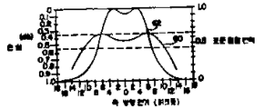
이 파장 의존 관계를 설명하기 위해, 제 35 도는 특정한 결합기의 기하학적인 파라메타에 대한 결합 전력대 가시스펙트럼 및 적외선 스펙트럼내의 신호 파장의 관계를 도시한 것이다. 이 결합기 형태의 경우, 결합기의 유효상호작용 길이가 파장이 720㎚인 경우에는 결합 길이의 홀수배로 되고 파장이 550㎚인 경우에는 결합 길이의 짝수배로 되기 때문에, 파장 720㎚는 100% 결합되고, 파장 550㎚는 효율적으로 비결합된다. 상이한 효율로, 상이한 파장들이 결합되거나 분리될 수 있다. 예를들어, 590㎚ 및 650㎚는 80% 효율로 분리 되거나 결합될 수 있다.To illustrate this wavelength dependence, FIG. 35 shows the relationship between the coupling power versus visible spectrum and signal wavelength in the infrared spectrum for the geometric parameters of a particular coupler. In the case of this type of coupler, the effective interaction length of the coupler is an odd multiple of the bond length when the wavelength is 720 nm and an even multiple of the bond length when the wavelength is 550 nm. The wavelength 550 nm is effectively uncoupled. With different efficiencies, different wavelengths can be combined or separated. For example, 590 nm and 650 nm can be separated or combined at 80% efficiency.
사실상, 소정 쌍의 파장(λ1, λ2)는 유효 상호 작용길이가 1 파장인 경우에 결합 길이의 짝수로 되고 다른 파장의 경우에 결합 길이의 홀수배로 되는 한 효율적으로 결합되거나 분리될 수 있다. 이미 기술한 바와 같이, 유효 상호작용 길이 내의 결합 길이의 수가 증가하면, 멀티플렉서의 해상도가 향상된다. 상술한 바와 같이, 유효 상호작용 길이는 주로 결합기(10)의 곡선 반경 R의 함수이므로, 멀티플렉서 해상도는 곡선반경 R을 증가시킴으로써 향상될 수 있다. 결합기의 상호 작용 길이가 충분히 크면, 2 개의 신호들은, 이 신호들의 파장들이 얼마나 밀접하게 간격을 두고 떨어져 있는 가에 관계없이, 정확히 혼합되거나 분리될 수 있다.In fact, certain pairs of wavelengths [lambda] 1, [lambda] 2 can be effectively combined or separated as long as the effective interaction length is one wavelength and the odd length of the bond length for other wavelengths. As already described, as the number of coupling lengths within the effective interaction length increases, the resolution of the multiplexer is improved. As mentioned above, since the effective interaction length is primarily a function of the curve radius R of the
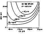
제 29 도 및 제 30 도를 참조하여 기술한 바와같이, 결합길이가 전형적인 단일 모우드 광학섬유의 경우에 중요한 스펙트럼 범위 내에서 최소치를 나타내므로, 이 저해상도 지점에서 멀리 떨어져서 멀티플렉서를 동작 시키도록 주의를 해야한다. 제 29 도 및 제 30 도를 참조하여 기술한 바와같이, 최소 결합 길이의 위치는 최소 광학섬유 간격에 따라 변한다. 그러므로, 이 파라메타는 높은 결합 편차를 위해 결합기를 해당 파장 범위내에 양호하게 바이어스 시키기 위해 사용될 수 있다.As described with reference to FIGS. 29 and 30, care must be taken to operate the multiplexer away from this low resolution point, as the bond length represents a minimum within the critical spectral range for a typical single-mode optical fiber. do. As described with reference to FIGS. 29 and 30, the position of the minimum bond length varies with the minimum fiber optic spacing. Therefore, this parameter can be used to better bias the coupler within the wavelength range for high coupling variation.
제 12 도를 참조하여 기술한 바와같이, 상호 작용길이는 파장의 함수히고, 해상도는 (R-1/2)에 거의 비례한다. R이 증가하면, 유효 상호작용 길이가 증가하여, 결합길이의 더 높은 배수로 되어, 해상도가 개량된다. 이 결과는 유효 상호작용 길이가 증가하여 더 높은 결합길이의 배수로되어, 해상도가 개량하는 것으로 제 33 도에 도시되어 있다. 이 결과는 곡선 반경이 200㎝로 증가되어 있는 것을 제외하면, 제 32 도의 그래프와 비교될 수 있는, 제 33 도에 도시되어 있다. 예상한 바와같이, 이 반경증가는 λ=600㎚ 부근에서의 결합기 해상도를 25㎝ 반경에서의 약 170㎚로부터 200㎝ 경우의 약 60㎚로 개량시킨다. 또한, 제 29 도로부터 예상한 바와같이, 결합 길이가 λ=1 미크론에서 최소인데, 이것은 이미 설명한 바와같이 이 범위내의 더 불충분한 해상도를 나타낸다.As described with reference to FIG. 12, the interaction length is a function of wavelength, and the resolution is almost proportional to (R- 1 / 2 ). As R increases, the effective interaction length increases, resulting in a higher multiple of the bond length, improving resolution. This result is shown in FIG. 33 as the effective interaction length increases to a multiple of the higher bond length, resulting in improved resolution. This result is shown in FIG. 33, which can be compared with the graph of FIG. 32, except that the curve radius is increased to 200 cm. As expected, this radius increase improves coupler resolution around λ = 600 nm from about 170 nm at 25 cm radius to about 60 nm at 200 cm. In addition, as expected from FIG. 29, the bond length is minimal at λ = 1 micron, which indicates a more insufficient resolution within this range as already described.
제 12 도를 참조하면, 유효 상호작용 길이가 파장의 함수로 되는 것으로 도시되어 있다. 제 29 도 및 제 30 도를 참조하여 기술한 바와같이, 결합 길이가 도한 파장의 영향을 받기 때문에, 멀티플렉서 해상도를 정하는 유효상호 작용 길이 내의 결합길이의배수는 이 파장 의존관계들의 영향을 받는다. 이 점에 관해서, 제 34 도는 결합길이로 나눈 유효 상호작용 길이의 상(quotient)이 최대치를 나타내고, 이 최대치와 이에 따라 생기는 파장이 최소 광학섬유 간격 H에 따라 변하는 상태를 도시한 것이다. 이미 기술한 바와같이, 제 34 도의 한 곡선의 최대치 근처에서 동작되는 멀티플렉서로 양호한 해상도를 얻기가 어렵다. 왜냐하면, 이 범위 근처의 상이 파장에 따라 천천히 변하기 때문이다. 그러므로, 이 상의 기울기가 비교적 큰 범위내에서 멀티플렉싱 결합기를 동작시키는 것이 매우 바람직하다. 제 34 도로부터, 이 목적은 소정파장 상의 경우에 광학섬유 간격인 파라메타 H를 양호하게 선택함으로써 이루어질 수 있다는 것을 알 수 있다. 예를 들어, 유효 멀티플렉싱이 제 1 형태의 광학섬유에서 0.9 미크론의 파장 근처에서 바람직하게 되면, 5 내지 6 미크론의 광학섬유 간격은 더 높은 기울기를 제공하므로, 해상도를 더욱 좋게 한다.Referring to FIG. 12, the effective interaction length is shown as a function of wavelength. As described with reference to FIGS. 29 and 30, since the bond length is also affected by the wavelength, the multiple of the bond length within the effective interaction length that defines the multiplexer resolution is affected by these wavelength dependencies. In this regard, Fig. 34 shows a state in which the phase of the effective interaction length divided by the bond length shows the maximum value, and this maximum value and the resulting wavelength vary according to the minimum optical fiber spacing H. As already described, it is difficult to obtain good resolution with a multiplexer operating near the maximum of one curve in FIG. This is because the phase near this range changes slowly with the wavelength. Therefore, it is highly desirable to operate the multiplexing coupler within a range where the phase slope is relatively large. It can be seen from FIG. 34 that this object can be achieved by good selection of parameter H, which is an optical fiber spacing, for a given wavelength. For example, if effective multiplexing is desired near a wavelength of 0.9 micron in the first type of optical fiber, the 5 to 6 micron optical fiber spacing provides a higher slope, resulting in better resolution.
최고 광학섬유 H가 결정되면, 곡선반경 R은 멀티플렉스될 주파수 상들에 필요한 (λ1 -λ2) 주파수 분리를 제공하도록 선택될 수 있다. 이 관계는 이미 설명되었고, 유효 상호작용 길이는 곡선 반경의 함수로 되며, 분기될 2 개의 주파수의 경우의 결합 길이에 대한 홀수/짝수 배수 필요조건으로 된다. 곡선 반경 R의 변화는 유효 상호작용 길이에만 비례하고, 결합 길이에는 비례하지 않는다. 그러므로, 제 34 도의 곡선의 최대치 위치는 결합길이 (제 29 도 및 제 30 도)의 최소치 위치의 함수이므로, 반경 R의 변화는 제 34 도의 곡선 들의 최대치를 거의 편기시키지 않고서 이 곡선들에 비례한다.Once the highest fiber H is determined, the curve radius R can be selected to provide the (λ 1 -λ 2) frequency separation required for the frequency phases to be multiplexed. This relationship has already been explained, and the effective interaction length becomes a function of the radius of the curve and becomes an odd / even multiple requirement for the combined length in the case of two frequencies to branch. The change in curve radius R is only proportional to the effective interaction length and not the bond length. Therefore, since the maximum position of the curve of FIG. 34 is a function of the minimum position of the coupling length (FIGS. 29 and 30), the change in radius R is proportional to these curves with little deviation of the maximum of the curves of FIG. 34. .
그러므로, 멀티플렉싱 결합기의 해상도는 2 개의 독립파라메타, 즉 H(광학섬유 간격) 및 R(광학섬유의 곡선변경)에 따라 변한다. 소정쌍의 신호 파장의 경우, 효율적으로 혼합시키는 것은 우선 해당 파장 근처에서 제 34 도의 상에 대해 큰 파장 의존 관계를 발생시키는 결합기에 대한 광학섬유 간격을 양호하게 선택한후 (H의 선택), 그다음 파장들 사이의 차와 동일한 해상도를 발생시키는 곡선 반경을 선택 (R의 선택) 함으로써 이론적으로 이루어질 수 있다.Therefore, the resolution of the multiplexing coupler varies with two independent parameters: H (optical fiber spacing) and R (optical fiber curve change). For a given pair of signal wavelengths, mixing efficiently involves first selecting a good optical fiber spacing for the coupler that produces a large wavelength dependence for the image in FIG. 34 near that wavelength (selection of H), and then the wavelength. Theoretically can be done by selecting a radius of curvature (selection of R) which produces the same resolution as the difference between them.
결합기의 해상도가 분리될 파장에 따라 셋트된 후, 결합기는 유효 상호작용 길이가 한 파장의 결합 길이의 짝수 배로되고 다른 파장의 결합 길이의 홀수배로 되도록 해당 파장에 대해 겨합 길이를 정확하게 조정하기 위해 동조될 수 있다. 이것은 제 16 도 및 제 17 도를 참조하여 기술한 바와같이, 광학섬유를 편기시킴으로서 이루어진다. 이미 기술한 바와같이, 이러한 편기는 최소 광학섬유 간격 H를 증가시키고 광학섬유의 유효 곡선 반경을 증가시키는 효과를 갖고 있다. 요구된 편기가 매우 작으면, 멀티플렉서 해상도를 나쁘게 하지 않는다. 이것은 큰 반경 결합기의 간격 H가 광학섬유 편기에 따른 유효 곡선 반경의 변화와 비교하여 광학섬유 편기에 따라 신속하게 변한다는 사실로부터 유래된다.After the resolution of the combiner is set according to the wavelength to be separated, the combiner is tuned to precisely adjust the combined length for that wavelength so that the effective interaction length is an even multiple of the bond length of one wavelength and an odd multiple of the bond length of the other wavelength. Can be. This is done by knitting the optical fibers, as described with reference to FIGS. 16 and 17. As already described, this knitting machine has the effect of increasing the minimum optical fiber spacing H and increasing the effective curve radius of the optical fiber. If the required knitting is very small, it does not degrade the multiplexer resolution. This is derived from the fact that the spacing H of the large radius coupler changes rapidly with the optical fiber knitting compared to the change of the effective curve radius due to the optical fiber knitting.
멀티플렉싱 결합기의 동조 능력을 설명하기 위해, 제 35 도는 광학섬유 편기의 3 개의 증가치(0 미크론, 0.5 미크론 및 1.0 미크론)에 대한 상대 결합 전력 대 파장의 그래프가 도시되어 있다. 이 곡선은 편기가 증가할 때 증가 파장을 향해 전이되는 것으로 도시되어 있으나, 진동(또는, 해상도)의 주기는 거의 변하지 않는다. 이 특정한 예 (R=200㎝, H=4미크론)에서, 1 미크론 편기는 곡선을 약 45㎚ 정도 전이시킨다.To illustrate the tuning capability of the multiplexing coupler, FIG. 35 shows a graph of relative binding power versus wavelength for three increments (0 micron, 0.5 micron and 1.0 micron) of optical fiber knitting. This curve is shown to shift toward increasing wavelengths when the knitting is increased, but the period of vibration (or resolution) hardly changes. In this particular example (R = 200 cm, H = 4 microns), a 1 micron knitting group shifts the curve by about 45 nm.
전술한 설명으로부터, 소정 쌍의 파장(λ1, λ2)에서 유효한 멀티플렉서의 설계는 다음 수단들을 포함한다는 것을 알 수 있다.From the foregoing description, it can be seen that the design of a multiplexer effective at a predetermined pair of
1. 최소 광학섬유 간격은 해당 주파수들이 제 34 도의 곡선의 최대치로부터 멀리 떨어지도록 선택된다.1. The minimum optical fiber spacing is chosen such that the frequencies fall away from the maximum of the curve of FIG. 34.
2. 곡선 반경 R은 요구된 해상도를 달성하도록 선택된다. 즉, 곡선 반경은 상술한 홀수/짝수 배수 관계를 제공하도록 유효 상호작용 길이내의 필요한 길이수를 제공하는 상호 작용 길이가 생기게 한다.2. The curve radius R is chosen to achieve the required resolution. That is, the curve radius results in an interaction length that provides the required number of lengths within the effective interaction length to provide the odd / even multiple relationship described above.
3. 제조후, 멀티플렉서는 파장 해상도를 크게 변형시키지 않고서 파장(λ1 및 λ2)에서의 결합에 악영향을 미치는 광학섬유 간격 H를 증가시키기 위해 2 개의 광학섬유를 편기시킴으로써 조정된다. 결합기(10)은 제 36 도에 도시한 동조 장치(70)에 의하여 상술한 개념들에 따라 기계적으로 동조될 수 있다. 이 장치(70)은 계단식 U형 채널(72)를 갖고 있는 마이크로미터 캐리지(carriage, 71)을 포함한다. 채널(72)의 하부(74)는 상부(76)보다 좁고, 결합기 블록(16B)를 견고하게 장착하기 위한 크기로 되어 있으며, 블록(16B)의 저면은 채널(72)의 저면위에 있다. 채널(72)의 상부(76)과 하부(74) 사이에는 계단식 이동부분(79)가 있다. 상부(76)과 하부(74) 사이의 계단식 이동부분(97)는 블록의 대향표면(14)밑에 있으므로, 상부 블록(16A)는 채널(76)에 수직 방향으로 이동될 수 있다. 결합기(10)은 이러한 이동이 접촉 표면(18)을 측방향으로 편기시킬 수 있게 하기 위해 가닥(12)가 채널(72)에 평행한 방향으로 있도록 배향되어 있다.3. After manufacture, the multiplexer is adjusted by knitting two optical fibers to increase the optical fiber spacing H, which adversely affects bonding at
한쌍의 원통형 리테이너(78)은 채널(72)의 상부(76)의 한 측벽으로부터 돌출하도록 미끄러질 수 있게 장착되어 있다. 이 리테이너(78)은 블록(16A)의 한 측면을 누르도록 스프링 하중 되어 있다. 차동 마이크로미터(80)은 채널 상부(76)의 대향 측벽상에 장착되어 있다. 이 마이크로미터(80)은 블록(16A)의 대향 측면을 누르므로, 블록(16A)는 마이크로미터(80)과 스프링 바이어스리테이너(78) 사이에 유지된다.The pair of cylindrical retainers 78 are slidably mounted to protrude from one sidewall of the top 76 of the channel 72. This retainer 78 is spring loaded to press one side of the block 16A. The differential micrometer 80 is mounted on opposite sidewalls of the channel top 76. Since the micrometer 80 presses against the opposite side of the block 16A, the block 16A is held between the micrometer 80 and the spring bias retainer 78.
마이크로미터(80)을 회전시킴으로써, 블록(16A)의 위치는 접촉 표면(18)을 중첩시키도록 블록(16B)에 관련해서 조정될 수 있다. 블록(16)은 투명한 석영으로 구성되어 있기 때문에, 접촉 표면(18)의 상대 위치는 현미경을 이용함으로써 관찰될 수 있다. 표면(18)은 바람직한 경우에, 마이크로미터(80)을 회전시킴으로서 바람직한 결합 효율로 결합기(10)을 동조시키도록 중첩 위치로부터 측방향 편기될 수도 있다. 결합기(10)이 동조되면, 블록(16)은, 바람직한 경우에, 영구적으로나 반영구적으로 편기가 고정된 결합기를 제공하도록 함께 클램프(clamp) 되거나, 접착되거나 응용 될 수 있다.By rotating the micrometer 80, the position of the block 16A can be adjusted relative to the block 16B to overlap the
장치(70)은 블록(16)을 비틀도록 한 마이크로미터(80)을 회전시킴으로서 서로 관련해서 접촉 표면(18)을 회전시키기 위해 사용될 수도 있다.The
제 37 도는 본 발명의 멀티플렉싱 결합기가 더 큰 다수의 신호 파장들을 분리하기 위해 사용될 수 있는 방법을 개략적으로 도시한 것이다. 이 도면에서는, 다수의 멀티플렉싱 결합기(100-112)가 사용된다. 결합기(100)의 한 입력 광학 섬유는 λ1 내지 λ2로 표시된 8개의 분리된 광학 파장들이 이동되는 광학섬유에 결합된다. 이 시스템에서, 각각의 인접 광학섬유쌍의 주파수 간격, 즉(λ1 - λ2), (λ2 - λ3), (λ3 - λ4)등은 동일하고, △λ로 표시된다. 제 1 멀티플렉싱 결합기(100)은 △λ와 동일한 해상도를 각고 있으므로 파장 λ2, λ4, λ6 및 λ8 은 결합시키지만, 나머지 파장 λ1, λ2, λ5 및 λ7 은 비결합시킨다. 이 후자의 파장들은 결합기(102)의 광학섬유입력에 결합된다. 이와 마찬가지로, 파장 λ2, λ4, λ6 및 λ8 은 결합기(104)의 광학섬유 입력에 결합된다. 결합기(102 및 104)는 2△λ과 동일한 해상도를 갖고 있으므로 분리된 출력 광학섬유상에서 2△λ정도 간격을 두고 입력 파장들을 분리한다. 예를 들어, 결합기(102)는 파장 λ1 및 λ5를 결합시키지 않지만, 파장 λ3 및 λ7을 완전히 결합시킨다. 결합기(102 및 104)로부터의 광학섬유는 각각 4△λ의 해상도를 갖고 있는 결합기(106 내지 112)에 입력을 제공하므로 분리된 출력 광학섬유상에 입력 파장의 최종 간격을 제공한다. 방금 기술한 디멀티플렉싱 동작은 제 37 도에 도시한 바와같이 결합기(106 내지 112)의 적당한 광학섬유 상에 입력 파장( λ1 내지 λ8 )을 제공함으로써 반대로 될 수 있다. 이 멀티플렉싱 동작은 모든 파장들이 결합기(100)의 단일 출력광학섬유상에 결합되게 한다.37 schematically illustrates how the multiplexing combiner of the present invention can be used to separate a larger number of signal wavelengths. In this figure, multiplexing combiners 100-112 are used. One input optical fiber of the
이 시스템을 구성하기 위해서, 상술한 해상도는 상술한 설명에 따라 조정될 수 있고 각각의 멀티플렉싱 결합기에 대한 주파수는 결합기를 동조시킴으로서 선택될 수 있다. 결합기(102 및 104)에 대한 해상도는, 결합기(106 내지 112)에 대한 해상도와 공일하다. 그러므로, 이 결합기 그룹들은 구조는 동일하지만 다르게 동조되어, 필요한 주파수 선택을 하기 위해 제 36 도에 도시한 장치에 대해 3 개의 결합기 형태만을 필요로 한다.In order to construct this system, the above-described resolution can be adjusted according to the above description and the frequency for each multiplexing combiner can be selected by tuning the combiner. The resolution for combiners 102 and 104 is the same as the resolution for combiners 106-112. Therefore, these coupler groups are identical in structure but are tuned differently, requiring only three coupler types for the device shown in FIG. 36 to make the required frequency selection.
Claims (8)
Applications Claiming Priority (3)
| Application Number | Priority Date | Filing Date | Title |
|---|---|---|---|
| US319.301 | 1981-11-09 | ||
| US06/319,301 US4556279A (en) | 1981-11-09 | 1981-11-09 | Passive fiber optic multiplexer |
| US319301 | 1981-11-09 |
Publications (3)
| Publication Number | Publication Date |
|---|---|
| KR820002526A KR820002526A (en) | 1984-07-02 |
| KR840002526A KR840002526A (en) | 1984-07-02 |
| KR900002513B1 true KR900002513B1 (en) | 1990-04-16 |
Family
ID=23241684
Family Applications (1)
| Application Number | Title | Priority Date | Filing Date |
|---|---|---|---|
| KR8205069A KR900002513B1 (en) | 1981-11-09 | 1982-11-09 | Passive fiber optic multiplexer |
Country Status (11)
| Country | Link |
|---|---|
| US (1) | US4556279A (en) |
| EP (1) | EP0079196B1 (en) |
| JP (1) | JPS5888719A (en) |
| KR (1) | KR900002513B1 (en) |
| AT (1) | ATE25555T1 (en) |
| AU (1) | AU564991B2 (en) |
| BR (1) | BR8206459A (en) |
| CA (1) | CA1197931A (en) |
| DE (1) | DE3275488D1 (en) |
| IL (1) | IL67162A (en) |
| NO (1) | NO823710L (en) |
Families Citing this family (88)
| Publication number | Priority date | Publication date | Assignee | Title |
|---|---|---|---|---|
| EP0124523B1 (en) * | 1982-11-12 | 1990-01-31 | The Board Of Trustees Of The Leland Stanford Junior University | Fiber optic switch and discretely variable delay line |
| US4652079A (en) * | 1983-08-26 | 1987-03-24 | The Board Of Trustees Of The Leland Stanford Junior University | High speed pulse train generator |
| US4938556A (en) * | 1983-11-25 | 1990-07-03 | The Board Of Trustees Of The Leland Stanford Junior University | Superfluorescent broadband fiber laser source |
| US4674830A (en) † | 1983-11-25 | 1987-06-23 | The Board Of Trustees Of The Leland Stanford Junior University | Fiber optic amplifier |
| GB2150703B (en) * | 1983-11-30 | 1987-03-11 | Standard Telephones Cables Ltd | Single mode fibre directional coupler |
| GB2152694B (en) * | 1984-01-05 | 1987-06-24 | Standard Telephones Cables Ltd | Wavelength selective optical waveguide coupler |
| AU592066B2 (en) * | 1985-01-31 | 1990-01-04 | Ab Electronic Products Group Plc | Coupler for optical fibres |
| US4794598A (en) * | 1986-07-18 | 1988-12-27 | The Board Of Trustees Of The Leland Stanford Junior University | Synchronously pumped ring fiber Raman laser |
| US4738503A (en) * | 1985-02-08 | 1988-04-19 | The Board Of Trustees Of The Leland Stanford Junion University | In-line fiber optic memory |
| US4708421A (en) * | 1985-02-08 | 1987-11-24 | The Board Of Trustees Of The Leland Stanford Junior University | In-line fiber optic memory |
| US4815804A (en) * | 1985-02-08 | 1989-03-28 | The Board Of Trustees Of The Leland Stanford Junior University | In-line fiber optic memory and method of using same |
| GB2170920B (en) * | 1985-02-12 | 1988-09-07 | Stc Plc | Beam splitter/combers |
| US4681397A (en) * | 1985-06-28 | 1987-07-21 | Amp Incorporated | Optical switching arrangement |
| US4673270A (en) * | 1985-06-28 | 1987-06-16 | Amp Incorporated | Channel add/drop filter-coupler |
| US4761832A (en) * | 1985-06-28 | 1988-08-02 | Amp Incorporated | Fiber optic switching network |
| US4717230A (en) * | 1985-06-28 | 1988-01-05 | Amp Incorporated | Optical eraser and node switch for an optical network |
| US4768854A (en) * | 1985-07-11 | 1988-09-06 | Raychem Corp. | Optical fiber distribution network including nondestructive taps and method using same |
| GB8519183D0 (en) * | 1985-07-30 | 1985-09-04 | British Telecomm | Optical fused couplers |
| US4834481A (en) * | 1985-11-12 | 1989-05-30 | Gould Inc. | In-line single-mode fiber optic multiplexer/demultiplexer |
| US4738511A (en) * | 1986-01-07 | 1988-04-19 | Litton Systems, Inc. | Molecular bonded fiber optic couplers and method of fabrication |
| US4810052A (en) * | 1986-01-07 | 1989-03-07 | Litton Systems, Inc | Fiber optic bidirectional data bus tap |
| US4828350A (en) * | 1986-01-17 | 1989-05-09 | The Board Of Trustees Of The Leland Stanford Junior University | Fiber optic mode selector |
| JPS63175812A (en) * | 1987-01-17 | 1988-07-20 | Nippon Telegr & Teleph Corp <Ntt> | Production of optical fiber coupler |
| US4915468A (en) * | 1987-02-20 | 1990-04-10 | The Board Of Trustees Of The Leland Stanford Junior University | Apparatus using two-mode optical waveguide with non-circular core |
| JPH07122683B2 (en) * | 1987-02-21 | 1995-12-25 | 日本電信電話株式会社 | Method for manufacturing optical fiber star coupler |
| US4844573A (en) * | 1987-05-22 | 1989-07-04 | Aster Corporation | Electro-optical converter including ridgid support for optical fiber coupler, telephone set using the coupler and method of making same |
| US4842368A (en) * | 1987-08-17 | 1989-06-27 | American Telephone And Telegraph Company | N×N single-mode optical waveguide coupler |
| US4964131A (en) * | 1988-12-16 | 1990-10-16 | The Board Of Trustees Of The Leland Standford Junior University | Broadband optical fiber laser |
| US4911526A (en) * | 1988-10-07 | 1990-03-27 | Eastman Kodak Company | Fiber optic array |
| US4923275A (en) * | 1988-10-07 | 1990-05-08 | Eastman Kodak Company | Fiber optic array |
| US4880494A (en) * | 1988-10-07 | 1989-11-14 | Eastman Kodak Company | Method of making a fiber optic array |
| US4875969A (en) * | 1988-10-07 | 1989-10-24 | Eastman Kodak Company | Method of making a fiber optic array |
| US4976512A (en) * | 1989-04-05 | 1990-12-11 | Safaai Jazi Ahmad | Narrowband fiberoptic spectral filter formed from fibers having a refractive index with a W profile and a step profile |
| US5108183A (en) * | 1989-08-31 | 1992-04-28 | The Board Of Trustees Of The Leland Stanford Junior University | Interferometer utilizing superfluorescent optical source |
| JPH03118506A (en) * | 1989-10-02 | 1991-05-21 | Nikko Kapura:Kk | Optical coupler and its manufacture |
| IT1236632B (en) * | 1989-10-24 | 1993-03-25 | Pirelli Cavi Spa | AMPLIFIER FOR FIBER OPTIC TELECOMMUNICATIONS LINES AND FIBER OPTIC TELECOMMUNICATIONS LINES INCORPORATING SAID AMPLIFIER |
| JPH0795130B2 (en) * | 1990-01-26 | 1995-10-11 | 株式会社精工技研 | Variable type optical branch / merge device |
| JPH03220509A (en) * | 1990-01-26 | 1991-09-27 | Seiko Giken:Kk | Multi-division optical branching/synthesizing device |
| JP2854942B2 (en) * | 1990-01-26 | 1999-02-10 | 住友電装株式会社 | Manufacturing method of optical branching coupler |
| JPH03220507A (en) * | 1990-01-26 | 1991-09-27 | Seiko Giken:Kk | Multi-division optical branching/synthesizing device |
| IT1237980B (en) * | 1990-02-12 | 1993-06-19 | Pirelli Cavi Spa | CURVED SINGLE-MODE ACTIVE FIBER OPTICAL AMPLIFIER |
| US5155621A (en) * | 1990-07-31 | 1992-10-13 | Fujitsu Limited | Optical fiber amplifier |
| CA2022367C (en) * | 1990-07-31 | 2002-12-17 | Kenneth O. Hill | Simplified wdm fused fiber coupler design |
| US5106193A (en) * | 1990-08-09 | 1992-04-21 | The Board Of Trustees Of The Leland Stanford Junior University | Optical waveguide amplifier source gyroscope |
| JPH04145403A (en) * | 1990-10-05 | 1992-05-19 | Seiko Giken:Kk | Branching and joining device for multiple optical fiber ribbon tape and its production |
| US5166994A (en) * | 1991-03-05 | 1992-11-24 | Aster Corporation | Low cost one by eight singlemode optical fiber coupler |
| JPH0743455B2 (en) * | 1991-09-24 | 1995-05-15 | 株式会社精工技研 | Ribbon fiber optic connector |
| DE4228995C1 (en) * | 1992-08-31 | 1993-07-22 | Siemens Ag, 8000 Muenchen, De | Optical fibre coupling module - holds fibres in holders which have cutters to remove cladding when holders pushed together |
| JP3286972B2 (en) * | 1992-12-25 | 2002-05-27 | キヤノン株式会社 | Wavelength demultiplexer and wavelength division multiplexing communication system using the same |
| US5636300A (en) * | 1994-12-12 | 1997-06-03 | Corning Incorporated | MxO multiplex demultiplex component |
| US6220878B1 (en) | 1995-10-04 | 2001-04-24 | Methode Electronics, Inc. | Optoelectronic module with grounding means |
| US5546281A (en) * | 1995-01-13 | 1996-08-13 | Methode Electronics, Inc. | Removable optoelectronic transceiver module with potting box |
| US5717533A (en) | 1995-01-13 | 1998-02-10 | Methode Electronics Inc. | Removable optoelectronic module |
| JP3175559B2 (en) * | 1995-07-03 | 2001-06-11 | 住友電装株式会社 | Manufacturing method of optical branching coupler |
| US5808764A (en) * | 1995-12-28 | 1998-09-15 | Lucent Technologies, Inc. | Multiple star, passive optical network based on remote interrogation of terminal equipment |
| US6026205A (en) * | 1997-01-21 | 2000-02-15 | Molecular Optoelectronics Corporation | Compound optical waveguide and filter applications thereof |
| AU2262397A (en) * | 1997-02-06 | 1998-08-26 | Optrand, Inc. | Fuel injectors with integral fiber optic pressure sensors and associated compensation and status monitoring devices |
| US7576909B2 (en) | 1998-07-16 | 2009-08-18 | Imra America, Inc. | Multimode amplifier for amplifying single mode light |
| US7656578B2 (en) | 1997-03-21 | 2010-02-02 | Imra America, Inc. | Microchip-Yb fiber hybrid optical amplifier for micro-machining and marking |
| US5949930A (en) * | 1997-07-23 | 1999-09-07 | Litton Systems, Inc. | Apparatus and method for scale factor stabilization in interferometric fiber optic rotation sensors |
| US6733166B2 (en) | 1997-12-09 | 2004-05-11 | Federal -Mogul World Wide, Inc. | Illuminated interior article system utilizing a Y-branch waveguide |
| US6179627B1 (en) | 1998-04-22 | 2001-01-30 | Stratos Lightwave, Inc. | High speed interface converter module |
| US6203333B1 (en) | 1998-04-22 | 2001-03-20 | Stratos Lightwave, Inc. | High speed interface converter module |
| US7090509B1 (en) | 1999-06-11 | 2006-08-15 | Stratos International, Inc. | Multi-port pluggable transceiver (MPPT) with multiple LC duplex optical receptacles |
| US6220873B1 (en) | 1999-08-10 | 2001-04-24 | Stratos Lightwave, Inc. | Modified contact traces for interface converter |
| US6597833B1 (en) | 2000-06-27 | 2003-07-22 | Oluma, Inc. | Wavelength-division multiplexers and demultiplexers based on mach-zehnder interferometers and evanescent coupling |
| US6625349B2 (en) | 2000-06-27 | 2003-09-23 | Oluma, Inc. | Evanescent optical coupling between a waveguide formed on a substrate and a side-polished fiber |
| US6501875B2 (en) | 2000-06-27 | 2002-12-31 | Oluma, Inc. | Mach-Zehnder inteferometers and applications based on evanescent coupling through side-polished fiber coupling ports |
| US6621951B1 (en) | 2000-06-27 | 2003-09-16 | Oluma, Inc. | Thin film structures in devices with a fiber on a substrate |
| US6516114B2 (en) | 2000-06-27 | 2003-02-04 | Oluma, Inc. | Integration of fibers on substrates fabricated with grooves |
| US6490391B1 (en) | 2000-07-12 | 2002-12-03 | Oluma, Inc. | Devices based on fibers engaged to substrates with grooves |
| US6621952B1 (en) | 2000-08-10 | 2003-09-16 | Oluma, Inc. | In-fiber variable optical attenuators and modulators using index-changing liquid media |
| US6571035B1 (en) | 2000-08-10 | 2003-05-27 | Oluma, Inc. | Fiber optical switches based on optical evanescent coupling between two fibers |
| US6542663B1 (en) | 2000-09-07 | 2003-04-01 | Oluma, Inc. | Coupling control in side-polished fiber devices |
| US6516131B1 (en) | 2001-04-04 | 2003-02-04 | Barclay J. Tullis | Structures and methods for aligning fibers |
| US6965721B1 (en) * | 2001-04-18 | 2005-11-15 | Tullis Barclay J | Integrated manufacture of side-polished fiber optics |
| US6719608B1 (en) | 2001-04-19 | 2004-04-13 | Oluma, Inc. | Fabrication of devices with fibers engaged to grooves on substrates |
| US6744948B1 (en) | 2001-06-20 | 2004-06-01 | Oluma, Inc. | Fiber tap monitor based on evanescent coupling |
| GB2380257B (en) * | 2001-09-28 | 2005-03-23 | Protodel Internat Ltd | Monitor for an optical fibre |
| JP2003156644A (en) * | 2001-11-21 | 2003-05-30 | Seiko Epson Corp | Directional coupler and device for optical communication |
| US7609918B2 (en) * | 2002-05-28 | 2009-10-27 | Optun (Bvi) Ltd. | Method and apparatus for optical mode division multiplexing and demultiplexing |
| US7269190B2 (en) * | 2002-10-02 | 2007-09-11 | The Board Of Trustees Of The Leland Stanford Junior University | Er-doped superfluorescent fiber source with enhanced mean wavelength stability |
| JP4058355B2 (en) * | 2003-01-21 | 2008-03-05 | 株式会社フジクラ | Optical fiber coupler |
| CN100378478C (en) * | 2006-04-28 | 2008-04-02 | 中国科学技术大学 | Mode selector with polishing function for multi-mode optical fiber |
| WO2010050975A1 (en) * | 2008-10-31 | 2010-05-06 | Hewlett-Packard Development Company, L.P. | Optical beam couplers and splitters |
| JP6059560B2 (en) * | 2013-03-04 | 2017-01-11 | 日本電信電話株式会社 | Multimode transmission optical amplifier |
| CN114074284A (en) * | 2021-10-05 | 2022-02-22 | 桂林电子科技大学 | Device capable of realizing high-precision batch side-polishing of optical fibers |
| CN113805280A (en) * | 2021-10-05 | 2021-12-17 | 桂林电子科技大学 | Stable and easy coaxial double wave light guide fiber lateral coupler of preparation |
Family Cites Families (15)
| Publication number | Priority date | Publication date | Assignee | Title |
|---|---|---|---|---|
| GB1094639A (en) * | 1966-05-31 | 1967-12-13 | Standard Telephones Cables Ltd | A thin film surface wave mode dielectric waveguide |
| US3957341A (en) * | 1974-09-03 | 1976-05-18 | The United States Of America As Represented By The Secretary Of The Navy | Passive frequency-selective optical coupler |
| JPS54101334A (en) * | 1978-01-27 | 1979-08-09 | Nippon Telegr & Teleph Corp <Ntt> | Optical fiber coupling element and production of the same |
| US4300811A (en) * | 1978-08-28 | 1981-11-17 | Rca Corporation | III-V Direct-bandgap semiconductor optical filter |
| JPS5576308A (en) * | 1978-12-05 | 1980-06-09 | Nippon Telegr & Teleph Corp <Ntt> | Optical period waveform branching filter |
| US4315666A (en) * | 1979-03-19 | 1982-02-16 | Hicks Jr John W | Coupled communications fibers |
| US4342499A (en) * | 1979-03-19 | 1982-08-03 | Hicks Jr John W | Communications tuning construction |
| DE2916234A1 (en) * | 1979-04-21 | 1980-10-30 | Philips Patentverwaltung | COUPLING DEVICE COUPLING OPTICAL SIGNALS INTO A OR FROM A TRANSFER FIBER |
| US4243297A (en) * | 1979-06-27 | 1981-01-06 | International Communications And Energy, Inc. | Optical wavelength division multiplexer mixer-splitter |
| US4307933A (en) * | 1980-02-20 | 1981-12-29 | General Dynamics, Pomona Division | Optical fiber launch coupler |
| US4301543A (en) * | 1980-02-20 | 1981-11-17 | General Dynamics Corporation, Pomona Division | Fiber optic transceiver and full duplex point-to-point data link |
| JPS56128904A (en) * | 1980-03-14 | 1981-10-08 | Nippon Telegr & Teleph Corp <Ntt> | Optical branching filter |
| US4493528A (en) * | 1980-04-11 | 1985-01-15 | Board Of Trustees Of The Leland Stanford Junior University | Fiber optic directional coupler |
| US4335933A (en) * | 1980-06-16 | 1982-06-22 | General Dynamics, Pomona Division | Fiber optic wavelength demultiplexer |
| US4343532A (en) * | 1980-06-16 | 1982-08-10 | General Dynamics, Pomona Division | Dual directional wavelength demultiplexer |
-
1981
- 1981-11-09 US US06/319,301 patent/US4556279A/en not_active Expired - Lifetime
-
1982
- 1982-11-02 IL IL67162A patent/IL67162A/en not_active IP Right Cessation
- 1982-11-04 DE DE8282305851T patent/DE3275488D1/en not_active Expired
- 1982-11-04 EP EP82305851A patent/EP0079196B1/en not_active Expired
- 1982-11-04 AT AT82305851T patent/ATE25555T1/en not_active IP Right Cessation
- 1982-11-08 JP JP57197416A patent/JPS5888719A/en active Granted
- 1982-11-08 AU AU90233/82A patent/AU564991B2/en not_active Expired - Fee Related
- 1982-11-08 BR BR8206459A patent/BR8206459A/en unknown
- 1982-11-08 CA CA000415105A patent/CA1197931A/en not_active Expired
- 1982-11-08 NO NO823710A patent/NO823710L/en unknown
- 1982-11-09 KR KR8205069A patent/KR900002513B1/en active
Also Published As
| Publication number | Publication date |
|---|---|
| ATE25555T1 (en) | 1987-03-15 |
| AU564991B2 (en) | 1987-09-03 |
| CA1197931A (en) | 1985-12-10 |
| AU9023382A (en) | 1983-05-19 |
| JPH0519131B2 (en) | 1993-03-15 |
| NO823710L (en) | 1983-05-10 |
| BR8206459A (en) | 1983-09-27 |
| IL67162A (en) | 1985-09-29 |
| KR840002526A (en) | 1984-07-02 |
| IL67162A0 (en) | 1983-03-31 |
| EP0079196A1 (en) | 1983-05-18 |
| US4556279A (en) | 1985-12-03 |
| DE3275488D1 (en) | 1987-04-02 |
| EP0079196B1 (en) | 1987-02-25 |
| JPS5888719A (en) | 1983-05-26 |
Similar Documents
| Publication | Publication Date | Title |
|---|---|---|
| KR900002513B1 (en) | Passive fiber optic multiplexer | |
| KR890000582B1 (en) | Method of manufacturing a fiber optic directional coupler | |
| CA1251072A (en) | Fiber optic switch and discretely variable delay line | |
| EP0037793B1 (en) | Optical communication transmission system | |
| KR900007557B1 (en) | Molecular bonded filber optic couplers and method of fabrication | |
| US6038359A (en) | Mode-routed fiber-optic add-drop filter | |
| US4673270A (en) | Channel add/drop filter-coupler | |
| US4306765A (en) | Branch component comprising optical light waveguides | |
| US5940555A (en) | Optical multiplexer/demultiplexer | |
| US4560234A (en) | Fiber optic switchable coupler | |
| US6026205A (en) | Compound optical waveguide and filter applications thereof | |
| EP2321680B1 (en) | Method and system for coupling radiation | |
| US6115520A (en) | Compact mach-zehnder interferometer and wavelength reference employing same | |
| EP0822428A1 (en) | Method and apparatus for atomic absorption-spectroscopy | |
| EP0565308A1 (en) | Planar lens and low order array multiplexer | |
| DE2851625A1 (en) | Optical data transmission system wavelength demultiplexer - has junctions with mirrors controlling paths to detectors mounted on narrow band filters | |
| EP1113297A2 (en) | Arrayed waveguide grating multiplexer with tapered waveguides | |
| US5675675A (en) | Bandwidth-adjusted wavelength demultiplexer | |
| Zengerle et al. | Wavelength-selective directional coupler made of nonidentical single-mode fibers | |
| US6263128B1 (en) | Fiber unbalanced Mach-Zehnder interferometers with flat-top spectral response for application in wavelength division multiplexers | |
| AU743093B2 (en) | Phased fiber array for multiplexing and demultiplexing | |
| US20020181872A1 (en) | Optical interleaver with image transfer element | |
| KR100281552B1 (en) | Integrated Optical Variable Optical Attenuator Using Thermo-optic Effect | |
| EP1430342B1 (en) | Passband flattening in an arrayed waveguide grating | |
| JPH0234806A (en) | Demultiplexer/multiplexer and its manufacture |