KR900001231B1 - Rotating dry apparatus of wafer - Google Patents
Rotating dry apparatus of wafer Download PDFInfo
- Publication number
- KR900001231B1 KR900001231B1 KR1019860003137A KR860003137A KR900001231B1 KR 900001231 B1 KR900001231 B1 KR 900001231B1 KR 1019860003137 A KR1019860003137 A KR 1019860003137A KR 860003137 A KR860003137 A KR 860003137A KR 900001231 B1 KR900001231 B1 KR 900001231B1
- Authority
- KR
- South Korea
- Prior art keywords
- drying
- rotating body
- drying chamber
- wafer
- wafer cassette
- Prior art date
Links
Images


Classifications
-
- H—ELECTRICITY
- H01—ELECTRIC ELEMENTS
- H01L—SEMICONDUCTOR DEVICES NOT COVERED BY CLASS H10
- H01L21/00—Processes or apparatus adapted for the manufacture or treatment of semiconductor or solid state devices or of parts thereof
- H01L21/02—Manufacture or treatment of semiconductor devices or of parts thereof
-
- H—ELECTRICITY
- H01—ELECTRIC ELEMENTS
- H01L—SEMICONDUCTOR DEVICES NOT COVERED BY CLASS H10
- H01L21/00—Processes or apparatus adapted for the manufacture or treatment of semiconductor or solid state devices or of parts thereof
- H01L21/67—Apparatus specially adapted for handling semiconductor or electric solid state devices during manufacture or treatment thereof; Apparatus specially adapted for handling wafers during manufacture or treatment of semiconductor or electric solid state devices or components ; Apparatus not specifically provided for elsewhere
- H01L21/67005—Apparatus not specifically provided for elsewhere
- H01L21/67011—Apparatus for manufacture or treatment
- H01L21/67017—Apparatus for fluid treatment
- H01L21/67028—Apparatus for fluid treatment for cleaning followed by drying, rinsing, stripping, blasting or the like
- H01L21/67034—Apparatus for fluid treatment for cleaning followed by drying, rinsing, stripping, blasting or the like for drying
-
- F—MECHANICAL ENGINEERING; LIGHTING; HEATING; WEAPONS; BLASTING
- F26—DRYING
- F26B—DRYING SOLID MATERIALS OR OBJECTS BY REMOVING LIQUID THEREFROM
- F26B5/00—Drying solid materials or objects by processes not involving the application of heat
- F26B5/08—Drying solid materials or objects by processes not involving the application of heat by centrifugal treatment
-
- Y—GENERAL TAGGING OF NEW TECHNOLOGICAL DEVELOPMENTS; GENERAL TAGGING OF CROSS-SECTIONAL TECHNOLOGIES SPANNING OVER SEVERAL SECTIONS OF THE IPC; TECHNICAL SUBJECTS COVERED BY FORMER USPC CROSS-REFERENCE ART COLLECTIONS [XRACs] AND DIGESTS
- Y10—TECHNICAL SUBJECTS COVERED BY FORMER USPC
- Y10S—TECHNICAL SUBJECTS COVERED BY FORMER USPC CROSS-REFERENCE ART COLLECTIONS [XRACs] AND DIGESTS
- Y10S134/00—Cleaning and liquid contact with solids
- Y10S134/902—Semiconductor wafer
Landscapes
- Engineering & Computer Science (AREA)
- Physics & Mathematics (AREA)
- Microelectronics & Electronic Packaging (AREA)
- Power Engineering (AREA)
- Computer Hardware Design (AREA)
- Manufacturing & Machinery (AREA)
- General Physics & Mathematics (AREA)
- Condensed Matter Physics & Semiconductors (AREA)
- Health & Medical Sciences (AREA)
- General Engineering & Computer Science (AREA)
- Mechanical Engineering (AREA)
- Molecular Biology (AREA)
- Life Sciences & Earth Sciences (AREA)
- Cleaning Or Drying Semiconductors (AREA)
- Drying Of Solid Materials (AREA)
Abstract
Description
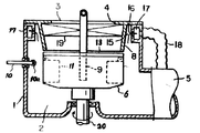
제1도는 본 발명의 제1의 실시예의 종단면.1 is a longitudinal section of a first embodiment of the present invention.
제2도는 제1도의 II-II선 평면 단면도.2 is a cross-sectional view taken along the line II-II of FIG.
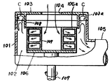
제3도는 본 발명의 제2의 실시예의 종단면.3 is a longitudinal section of a second embodiment of the present invention.
제4도는 종래 기술에 의한 회전 건조 장치의 종단면도.4 is a longitudinal sectional view of the rotary drying apparatus according to the prior art.
* 도면의 주요부분에 대한 부호의 설명* Explanation of symbols for main parts of the drawings
1 : 하우징 2 : 건조실1
3 : 뚜껑체 4 : 주입구3: cap body 4: injection hole
5 : 배기닥트 6 : 회전체5: exhaust duct 6: rotor
7 : 훼이퍼 카셋트 7a : 웨이퍼7: paper cassette 7a: wafer
8 : 차폐판 9 : 도관8: shielding plate 9: conduit
10 : 작동간 11 : 카셋트 홀더10: between operation 11: cassette holder
13 : 원형판 14 : 개구13: round plate 14: opening
16 : 스릿트 17 : 보조실16: split 17: auxiliary room
18 : 보조 닥트 19 : 에어휠터18: auxiliary doctor 19: air filter
본 발명은 반도체 기판(이하 웨이퍼라 한다.) 및 유리등의 판상체를 고속 회전시켜서 건조하는 기판의 회전 건조 장치의 관한 것이다.BACKGROUND OF THE INVENTION 1. Field of the Invention The present invention relates to a rotary drying apparatus for a substrate that is dried by rotating a plate-like body such as a semiconductor substrate (hereinafter referred to as a wafer) and glass at high speed.
특히, 본 발명은 린스(Rinse)공정과 건조 공정을 채용한 고속 회전 건조 장치에 관한 것이다.In particular, the present invention relates to a high speed rotary drying apparatus employing a rinse process and a drying process.
회전에 의해서 웨이퍼를 건조하는 것은 다수 제안된바 있으며, 그중에서 일본국 공개 특허 출원번호 소57-183038이 있으며, 이 장치는 첨부 도면 제4도로서 나타낸 장치로서 상세한 것은 이하에서 설명한다.A number of drying of the wafer by rotation has been proposed, among which there is Japanese Patent Application Laid-open No. 57-183038, which is shown in FIG.
제4도에 나타낸 바와 같은 회전 건조 장치는 공지된 것으로서 건조실(102)을 형성하는 하우징(101)을 포함하며, 회전체(106)은 건조실(102)내에서 회전토록 설치하고 회전축(109)에 지지 고정되어 있다. 회전체(106) 상면에 복수의 웨이퍼 케이스(107)을 삽탈할 수 있도록 장착하고 웨이퍼 케이스(107)에 수평으로 수납된 웨이퍼를 건조 처리토록 한 것이다. 뚜껑체(103)는 하우징(101) 상면에 두고, 뚜껑체(103)는 주입구(104)를 갖으며 이를 통하여 건조한 공기가 건조실(102)에 주입되어 진다.Rotating drying apparatus as shown in FIG. 4 is known and includes a
종래의 건조 장치는 환상 차폐판(108)을 갖으며 이는 뚜껑체(103)으로부터 하향하여 회전체(106)의 최상단 외주면보다 약간 밑까지 연장토록 하여서 상기 외주연이 환상 차폐판(108)으로 둘러싸게 한다. 회전체(106) 상면에 장착된 웨이퍼 케이스(107)에 건조할 웨이퍼를 수납하고 주입구(104)를 통하여 건조한 공기를 건조실(102)에 공급하면서 고속 회전을 행하여 건조 작업을 수행한다. 주입된 건조한 공기는 웨이퍼를 건조시키는데 사용하고 사용된 공기를 건조실(102)과 연통된 배기닥트(105)를 통하여 배출된다. 공기의 흐름이 제4도에서 화살표로서 표시되어 있다.The conventional drying apparatus has an
상술한 종래의 건조 장치에 있어서 환상 차폐판(108)은 회전체(106) 내부로 불필In the above-mentioned conventional drying apparatus, the
본 발명은 종래의 건조 장치의 전술한 난점을 해결하기 위한 것으로서, 특히, 본 발명의 근본적인 목적은 웨이퍼의 오염을 방지토록 하고, 또한 신속하고 안전하게 건조 작업을 행할 수 있도록 한 웨이퍼 회전 건조 장치를 제공하는데 있다.SUMMARY OF THE INVENTION The present invention has been made to solve the above-mentioned difficulties of the conventional drying apparatus, and in particular, a fundamental object of the present invention is to provide a wafer rotation drying apparatus which prevents contamination of the wafer and enables the drying operation to be performed quickly and safely. It is.
본 발명의 또 다른 목적과 잇점은 첨부 도면과 연관하여 실시예로서 상세히 설명하는 것으로부터 명백해질 것이다.Further objects and advantages of the present invention will become apparent from the following description in detail in connection with the accompanying drawings.
그리고, 상세한 설명과 실시예는 도시하기 위한 방편에 불과하며 본 발명의 기술 사상과 권리범위내에서 여러 형태의 변경이나 유형은 본 발명에 귀속됨을 이 분야에 종사자에게는 명백하다는 것을 알 것이다.And, it will be apparent to those skilled in the art that the detailed description and examples are merely for illustrative purposes and that various changes and types are within the scope of the invention within the spirit and scope of the invention.
전술한 목적을 성취하기 위해서, 본 발명의 일 실시예에서는 회전에 의해서 웨이퍼등을 건조시키는 장치를 제공하며, 상기와 같은 장치는 : 건조실을 가진 하우징 : 건조실의 하측방에 연통된 배기닥트 : 건조실내에서 회전토록 설치되고, 그 상면에 복수개의 건조할 웨이퍼를 장착할 수 있도록 한 회전체 : 회전체 내부로 불필요한 것들이 유입되는 것을 방지하고, 하향 연장되어 회전체와의 근소한 틈새를 두고 대향되도록 한 차폐판 장치 : 하우징 상부에 개폐토록 장착되고, 건조실로 청정 공기등을 주입할 수 있도록 주In order to achieve the above object, an embodiment of the present invention provides an apparatus for drying a wafer or the like by rotation, such an apparatus: a housing having a drying chamber: an exhaust duct connected to the lower side of the drying chamber: drying Rotating body which is installed to rotate indoors and can be equipped with a plurality of wafers to be dried on its upper surface: prevents unnecessary things from flowing into the rotating body and extends downward so as to face a small gap with the rotating body. Shielding board device: It is installed to open and close on the upper part of the housing, so that clean air can be injected into the drying room.
차폐판 장치는 회전체 직상부에 장착된 환상형이나 부분적인 원추형판으로 되어 있다.The shielding plate device is an annular or partial conical plate mounted directly on the rotating body.
회전체 상면에 최소한 한 개의 웨이퍼 카셋트 홀더를 회동토록 장착하여 복수개의 건조할 웨이퍼가 수납된 웨이퍼 카셋트를 장착할 수 있도록 한다.At least one wafer cassette holder is pivotally mounted on the upper surface of the rotating body so that a wafer cassette containing a plurality of wafers to be dried can be mounted.
홀더는 제일 위치에서 제이 위치로 이동이 되어서 홀더내로 웨이퍼 카셋트를 수납할 수 있도록 한다.The holder is moved from the first position to the second position to accommodate the wafer cassette into the holder.
또한, 원형판은 회전체 상부에 설치하여서 회전체 내부로 유입되는 불필요한 것등을 방지하며, 청정 공기는 원형판의 개구를 통하여 회전체 내부로 주입된다.In addition, the circular plate is installed on the upper portion of the rotating body to prevent unnecessary flow into the rotating body, and clean air is injected into the rotating body through the opening of the circular plate.
에어 휠터는 뚜껑체 직하부에 설치한다.The air filter is installed directly under the lid.
도관은 회전체 중심부에 수직 현수하고 그 원주 표면상에 미세공을 형성하여 웨이퍼를 향하여 소정의 용액이나 개스를 분출토록 한다.The conduit suspends perpendicularly to the center of the rotor and forms micropores on its circumferential surface to eject a predetermined solution or gas toward the wafer.
이하에서 본발명에 관련된 건조 장치를 첨부 도면 제 1도 및 제2도에 의거하여 설명한다.EMBODIMENT OF THE INVENTION Hereinafter, the drying apparatus which concerns on this invention is demonstrated based on FIG. 1 and FIG.
본 발명의 장치는, 건조실(2)을 가진 하우징(1), 회전체(6)는 건조실(2)에 회전토록 설치되고 모터(도시안됨)에 연동된 회전축(20)에 고정되어서 회전체(6)의 회전이 이루어진다.In the apparatus of the present invention, the housing (1) having a drying chamber (2), the rotating body (6) is installed to rotate in the drying chamber (2) and is fixed to the rotating shaft (20) interlocked with a motor (not shown) so that the rotating body ( 6) rotation is made.
배기닥트(5)는 건조실(2)의 하측방에 연통이 되어서 이를 통하여 건조중의 웨이퍼로부터 발생되는 수분, 수증기 및 분진등과 같은 불필요한 것들을 배기닥트(5) 타단에The exhaust duct 5 communicates with the lower side of the
웨이퍼 카셋트(7)를 각각 수납할 수 있는 복수개의 웨이퍼 카셋트 홀더(11)는 힌지(21)로서 회동이 되며, 회전체(6)의 측면에 대향되게 설치한다.The plurality of
웨이퍼 카셋트(7) 각각에는 복수개의 건조할 웨이퍼(7a)를 수납할 수 있도록 한다.Each of the
회전체(6) 상부에는 원형판(13)을 부착하여 불필요한 것들이 회전체(6) 내부로 유입되는 것을 방지토록 한다.A
원형판(13)은 제2도에 나타낸 것과 같이 개구(14)를 가지며 이를 통하여 청정공기를 주입토록 하고, 카셋트 홀더(11)에 상응되는 위치에 복수개의 놋취를 가져서 홀더(11)가 상향 회동시 계지토록 한다.The
하우징(1) 외벽 일측방에 일단에 접촉륜(10a)을 갖는 작동간(10)을 수평 방향으로 이동토록 설치하여, 이에 의해서 카셋트 홀더(11)를 화살표(B)방향으로 회동토록 한다.The operating section 10 having the
하우징(1) 상부면에 원형의 뚜껑체(3)를 두고 이를 힌지(도시안됨)에 의해서 개폐토록 부착한다.A circular lid 3 is placed on the upper surface of the housing 1, and attached to the housing 3 by a hinge (not shown).
뚜껑체(3)의 개폐 작동은 공기 실린더(도시안됨)에 의해서 행해진다.The opening and closing operation of the lid 3 is performed by an air cylinder (not shown).
뚜껑체(3)에는 주입구(4)를 가져서 이를 통하여 건조실(2)내로 청정공기를 주입한다. 뚜껑체(3)의 주입구(4) 직하부에는 에어휠터(19)를 장착하여 주입되는 공기를 청정시킨다.The lid 3 has an
부분 원추형 차폐판(8)은 회전체(6)의 직상부까지 하향 연장하여 차폐판(8)의 최하단부가 가능한한 회전체(6) 상단부인 원형판(13)의 상면까지 최근접시켜서 이 사이에 틈새를 통해서 회전체(6) 내부로 불필요한 것들이 유입되는 것을 방지토록 한다.The partially conical shield plate 8 extends downwardly to the upper portion of the rotating body 6 so as to be closest to the upper surface of the
부분 원추형 차폐판(8)은 불필요한 것들에 대해서 주 차폐판의 역할을 하며, 한편 원형판(13)은 부차적인 차폐판의 역할을 하는 것이다.The partially conical shield 8 serves as the main shield for unnecessary ones, while the
린스도관(9)은 회전체(6)의 중심부에 수직 현수한 도관이다. 도관(9)의 원주 표면상에는 미세공이 방사상으로 천설되어 있어서 이를 통하여 웨이퍼 카셋트(7)에 수납된 웨이퍼를 향하여 린스 용액을 분출한다. 필요하다면, 적절한 절환체(도시안됨)에 의해서 도관(9)에 불활성 개스를 공급할 수도 있다.The rinse conduit 9 is a conduit suspended vertically in the center of the rotor 6. Micropores are radially disposed on the circumferential surface of the conduit 9 to thereby eject the rinse solution toward the wafer housed in the
건조실(2) 내의 상부 원주 부위에 형성된 보조실(7)은 불필요한 것들을 집적하며, 건조실(2)과 연통이 되어 있으며 타방으로는 보조닥트(18)로 연결하여 배기닥트(5)와 연통되어 있다.The
작동을 설명하면, 건조시키고저 하는 복수개의 웨이퍼가 수납된 웨이퍼 카셋트(7)를 뚜껑체(3) 상면에 소정의 위치로 공급되어지고, 뚜껑체(3)는 공기 실린더(도시안됨)에 의해서 열려짐과 동시에 작동간(10)이 화살표 A로 표시된 방향으로 이동하여 작동간(10)의 접촉륜(10a)이 카셋트 홀더(11)를 밀게 된다. 그러면 카셋트 홀더(11)는 화살표 B로 표시된 것과 같이 상향 회동되어서 2점 쇄선으로 표시된 위치에서 카셋트 홀더(11)는 웨이터 카셋트(7)를 수납한다.In operation, the
다음, 작동간(10)은 다시 들어가고, 카셋트 홀더(11)는 원위치로 복귀한다.Then, the operation section 10 reenters and the
그리고, 회전체(6)는 180°회전하여, 상기한 작동을 반복하여 웨이퍼 카셋트(7)는 별개의 카셋트 홀더(11)에 수납되어 진다.Then, the rotating body 6 rotates 180 degrees, and the
그 후에 뚜껑체(3)는 닫혀지고, 회전체(6)의 회전은 시작된다.After that, the lid 3 is closed, and the rotation of the rotor 6 starts.
린스용액은 도관(9)의 미세공을 통하여 소정 기간 동안에 웨이퍼(7a)로 향하여 분출되어 진다.The rinse solution is ejected toward the wafer 7a for a predetermined period through the micropores of the conduit 9.
청정 공기는 뚜껑체(3)의 주입구(4)를 통하여 주입되어지고 에어휠터(19)를 통해서 건조실(2)로 유입된다.Clean air is injected through the
카셋트(7)에 수납된 웨이퍼는 린스를 행하게 되고 사용되어진 린스 용액과 주입된 공기는 회전체(6)의 외측으로 배출되어 진다. 사용된 용액과 주입된 공기는 배기닥트(5)를 통하여 배출되어 진다.The wafer contained in the
웨이퍼로부터 발생된 미세한 용액 방울, 수증기, 분진등과 같은 불필요한 것들의 잔량은 보조실(17)에 집적되어서 보조닥트(18)을 통하여 배출되어 이에 연결된 배기닥트(5)를 통하여 배출되어 진다.The remaining amount of unnecessary matters such as fine solution droplets, water vapor, dust, etc. generated from the wafer are accumulated in the
상기한 린스 공정 후에, 도관(9)로부터의 용액 분출은 정지되지만, 회전체(6)의 회전을 계속된다.After the above rinsing step, the solution ejection from the conduit 9 is stopped, but the rotation of the rotor 6 is continued.
웨이퍼 표면에 남아 있는 용액이나 수분은 회전체(6)의 원심력에 의해서 탈리되어 진다. 또한 동시에 청정공기가 뚜껑체(3)의 주입구(4)를 통하여 주입되어서 웨이퍼에게 공급함으로서 웨이퍼의 건조 공정이 촉진되는 것이다.The solution or water remaining on the wafer surface is released by the centrifugal force of the rotating body 6. At the same time, clean air is injected through the
건조 공정중에 회전체(6)로부터 취출된 불필요한 것들은 배기닥트(5)를 통하여 근본적으로 배출되어지며, 일부는 보조실(17)에 집적되어 진다.Unnecessary things taken out from the rotating body 6 during the drying process are essentially discharged through the exhaust duct 5, and some of them are integrated in the
린스 공정 중에는 물론 건조 공정 중에도 불필요한 것들이 회전체(6)의 내부로 유입될 수도 있다.Unnecessary things may flow into the rotor 6 during the rinsing process as well as during the drying process.
그러나, 차폐판(8)과 부차적인 차폐판(13)이 불필요한 것들이 유입을 방지토록 형성되어 있어서, 이들을 보조실(17)로 완전히 이송토록 한다.However, the unnecessary ones of the shielding plate 8 and the
따라서, 카셋트(7)에 수납된 웨이퍼는 어떠한 오염이나 훼손됨이 없이 깨끗하게 린스를 행하고 건조가 되어진다.Therefore, the wafer accommodated in the
제3도는 본 발명의 또 다른 실시예를 나타낸 것으로 제1도 및 제2도에서 나타낸 것과 동일한 또는 대응되는 부분의 예시부호 및 문자는 같으며, 설명이 중복되는 것은 이에 생략하기로 한다.3 is a view showing another embodiment of the present invention, and the same reference numerals and letters as those shown in FIGS. 1 and 2 are the same, and the description thereof will be omitted.
제3도에서 보조실(17)은 원추형 차폐판(8)에 대항되는 스릿트(16)를 갖으며, 뚜껑체(3)와는 별도로 되어있다.In FIG. 3 the
스릿트(16)는 건조실(2)과 보조실(17)을 연통 시킨다.The
도관(9)는 회전체(6) 중심부에서 뚜겅체(3)의 외곽까지 수직연장하여 지지장치(도시안됨)로 지지 고정되어 있다.The conduit 9 is vertically extended from the center of the rotor 6 to the outside of the lid 3 and is supported and fixed by a support device (not shown).
상기한 실시예에서, 보조닥트(18)는 배기닥트(5)와 연통되어 있지만, 보조닥트(18)를 또 다른 흡입펌프(도시안됨)에 직접 연결시킬 수도 있다.In the above embodiment, the
카셋트 홀더(11)의 수를 필요하다면 물론 증가시킬 수도 있다.The number of
도시한 실시예에서는 차폐판(8)이 뚜껑체(3)와 일체로 되어 있지만, 하우징(1) 몸체에 장착시킬 수도 있는 것이다.In the illustrated embodiment, the shielding plate 8 is integrated with the lid 3, but may be mounted on the housing 1 body.
Claims (6)
Applications Claiming Priority (2)
| Application Number | Priority Date | Filing Date | Title |
|---|---|---|---|
| JP1985063546U JPS61178187U (en) | 1985-04-26 | 1985-04-26 | |
| JP60-63546 | 1985-04-26 |
Publications (2)
| Publication Number | Publication Date |
|---|---|
| KR860008594A KR860008594A (en) | 1986-11-17 |
| KR900001231B1 true KR900001231B1 (en) | 1990-03-05 |
Family
ID=13232331
Family Applications (1)
| Application Number | Title | Priority Date | Filing Date |
|---|---|---|---|
| KR1019860003137A KR900001231B1 (en) | 1985-04-26 | 1986-04-23 | Rotating dry apparatus of wafer |
Country Status (3)
| Country | Link |
|---|---|
| US (1) | US4750505A (en) |
| JP (1) | JPS61178187U (en) |
| KR (1) | KR900001231B1 (en) |
Families Citing this family (54)
| Publication number | Priority date | Publication date | Assignee | Title |
|---|---|---|---|---|
| US5169408A (en) * | 1990-01-26 | 1992-12-08 | Fsi International, Inc. | Apparatus for wafer processing with in situ rinse |
| US6375741B2 (en) * | 1991-03-06 | 2002-04-23 | Timothy J. Reardon | Semiconductor processing spray coating apparatus |
| US5238503A (en) * | 1991-04-09 | 1993-08-24 | International Business Machines Corporation | Device for decontaminating a semiconductor wafer container |
| US5375291A (en) * | 1992-05-18 | 1994-12-27 | Tokyo Electron Limited | Device having brush for scrubbing substrate |
| US5224503A (en) * | 1992-06-15 | 1993-07-06 | Semitool, Inc. | Centrifugal wafer carrier cleaning apparatus |
| EP0632144B1 (en) * | 1993-06-30 | 1999-09-08 | Applied Materials, Inc. | Method of purging and pumping vacuum chamber to ultra-high vacuum |
| US5608943A (en) * | 1993-08-23 | 1997-03-11 | Tokyo Electron Limited | Apparatus for removing process liquid |
| US5475892A (en) * | 1993-10-29 | 1995-12-19 | Texas Instruments Incorporated | Semiconductor wafer particle extractor |
| US5509431A (en) * | 1993-12-14 | 1996-04-23 | Snap-Tite, Inc. | Precision cleaning vessel |
| US5417768A (en) * | 1993-12-14 | 1995-05-23 | Autoclave Engineers, Inc. | Method of cleaning workpiece with solvent and then with liquid carbon dioxide |
| US5672212A (en) * | 1994-07-01 | 1997-09-30 | Texas Instruments Incorporated | Rotational megasonic cleaner/etcher for wafers |
| US5634978A (en) * | 1994-11-14 | 1997-06-03 | Yieldup International | Ultra-low particle semiconductor method |
| US5849104A (en) * | 1996-09-19 | 1998-12-15 | Yieldup International | Method and apparatus for cleaning wafers using multiple tanks |
| US5958146A (en) * | 1994-11-14 | 1999-09-28 | Yieldup International | Ultra-low particle semiconductor cleaner using heated fluids |
| US5571337A (en) * | 1994-11-14 | 1996-11-05 | Yieldup International | Method for cleaning and drying a semiconductor wafer |
| US5772784A (en) * | 1994-11-14 | 1998-06-30 | Yieldup International | Ultra-low particle semiconductor cleaner |
| US6350319B1 (en) | 1998-03-13 | 2002-02-26 | Semitool, Inc. | Micro-environment reactor for processing a workpiece |
| US6264752B1 (en) | 1998-03-13 | 2001-07-24 | Gary L. Curtis | Reactor for processing a microelectronic workpiece |
| US6413436B1 (en) | 1999-01-27 | 2002-07-02 | Semitool, Inc. | Selective treatment of the surface of a microelectronic workpiece |
| US6318385B1 (en) | 1998-03-13 | 2001-11-20 | Semitool, Inc. | Micro-environment chamber and system for rinsing and drying a semiconductor workpiece |
| US6632292B1 (en) * | 1998-03-13 | 2003-10-14 | Semitool, Inc. | Selective treatment of microelectronic workpiece surfaces |
| TW452828B (en) * | 1998-03-13 | 2001-09-01 | Semitool Inc | Micro-environment reactor for processing a microelectronic workpiece |
| US6423642B1 (en) * | 1998-03-13 | 2002-07-23 | Semitool, Inc. | Reactor for processing a semiconductor wafer |
| US20050217707A1 (en) * | 1998-03-13 | 2005-10-06 | Aegerter Brian K | Selective processing of microelectronic workpiece surfaces |
| US6047717A (en) * | 1998-04-29 | 2000-04-11 | Scd Mountain View, Inc. | Mandrel device and method for hard disks |
| US6062239A (en) * | 1998-06-30 | 2000-05-16 | Semitool, Inc. | Cross flow centrifugal processor |
| US6125863A (en) * | 1998-06-30 | 2000-10-03 | Semitool, Inc. | Offset rotor flat media processor |
| US6432214B2 (en) | 1998-07-10 | 2002-08-13 | Semitool, Inc. | Cleaning apparatus |
| US6511914B2 (en) | 1999-01-22 | 2003-01-28 | Semitool, Inc. | Reactor for processing a workpiece using sonic energy |
| US6492284B2 (en) | 1999-01-22 | 2002-12-10 | Semitool, Inc. | Reactor for processing a workpiece using sonic energy |
| US6548411B2 (en) | 1999-01-22 | 2003-04-15 | Semitool, Inc. | Apparatus and methods for processing a workpiece |
| US6680253B2 (en) | 1999-01-22 | 2004-01-20 | Semitool, Inc. | Apparatus for processing a workpiece |
| US6806194B2 (en) * | 1999-01-22 | 2004-10-19 | Semitool. Inc. | Apparatus and methods for processing a workpiece |
| US7217325B2 (en) * | 1999-01-22 | 2007-05-15 | Semitool, Inc. | System for processing a workpiece |
| US6216710B1 (en) | 1999-02-05 | 2001-04-17 | Caterpillar Inc. | Method and apparatus for removing quench oil from a permeable metal part |
| US7438788B2 (en) | 1999-04-13 | 2008-10-21 | Semitool, Inc. | Apparatus and methods for electrochemical processing of microelectronic workpieces |
| US7264698B2 (en) | 1999-04-13 | 2007-09-04 | Semitool, Inc. | Apparatus and methods for electrochemical processing of microelectronic workpieces |
| JP4288010B2 (en) | 1999-04-13 | 2009-07-01 | セミトゥール・インコーポレイテッド | Workpiece processing apparatus having a processing chamber for improving the flow of processing fluid |
| US6774056B2 (en) * | 1999-11-10 | 2004-08-10 | Semitool, Inc. | Sonic immersion process system and methods |
| US6286231B1 (en) | 2000-01-12 | 2001-09-11 | Semitool, Inc. | Method and apparatus for high-pressure wafer processing and drying |
| US7102763B2 (en) * | 2000-07-08 | 2006-09-05 | Semitool, Inc. | Methods and apparatus for processing microelectronic workpieces using metrology |
| JP3662484B2 (en) * | 2000-08-09 | 2005-06-22 | エム・エフエスアイ株式会社 | Wet treatment method and wet treatment apparatus |
| JP2002079201A (en) * | 2000-09-07 | 2002-03-19 | Showa Kogyosho:Kk | Cleaning device for barrel type body to be cleaned |
| KR100689808B1 (en) * | 2000-12-07 | 2007-03-08 | 삼성전자주식회사 | Spin-dryer of wet station used to manufacture a semiconductor device |
| US20050061676A1 (en) * | 2001-03-12 | 2005-03-24 | Wilson Gregory J. | System for electrochemically processing a workpiece |
| WO2003008140A2 (en) * | 2001-07-16 | 2003-01-30 | Semitool, Inc. | Apparatus for processing a workpiece |
| AU2002343330A1 (en) * | 2001-08-31 | 2003-03-10 | Semitool, Inc. | Apparatus and methods for electrochemical processing of microelectronic workpieces |
| US7396412B2 (en) | 2004-12-22 | 2008-07-08 | Sokudo Co., Ltd. | Coat/develop module with shared dispense |
| US7699021B2 (en) | 2004-12-22 | 2010-04-20 | Sokudo Co., Ltd. | Cluster tool substrate throughput optimization |
| US7798764B2 (en) | 2005-12-22 | 2010-09-21 | Applied Materials, Inc. | Substrate processing sequence in a cartesian robot cluster tool |
| US7819079B2 (en) | 2004-12-22 | 2010-10-26 | Applied Materials, Inc. | Cartesian cluster tool configuration for lithography type processes |
| US7651306B2 (en) | 2004-12-22 | 2010-01-26 | Applied Materials, Inc. | Cartesian robot cluster tool architecture |
| KR102042635B1 (en) | 2012-07-02 | 2019-11-08 | 삼성전자주식회사 | Single type apparatus for drying a substrate and single type system for cleaning a substrate including the same |
| CN106716605B (en) * | 2014-09-30 | 2021-06-08 | 芝浦机械电子株式会社 | Substrate processing apparatus |
Family Cites Families (7)
| Publication number | Priority date | Publication date | Assignee | Title |
|---|---|---|---|---|
| US2893410A (en) * | 1952-07-17 | 1959-07-07 | Cornell Dubilier Electric | Washing electrolytic capacitor sections |
| JPS5212576A (en) * | 1975-07-21 | 1977-01-31 | Hitachi Ltd | Wafer washing drying device |
| WO1984004583A1 (en) * | 1980-04-23 | 1984-11-22 | Seiichiro Aigoo | Dryer |
| US4316750A (en) * | 1981-01-16 | 1982-02-23 | Western Electric Company, Inc. | Apparatus and method for cleaning a flux station of a soldering system |
| US4421131A (en) * | 1982-01-19 | 1983-12-20 | Auvil Jr Raymond G | Cleaning apparatus |
| JPS58190031A (en) * | 1982-04-30 | 1983-11-05 | Toshiba Corp | Semiconductor wafer cleaning and drying apparatus |
| JP3464837B2 (en) * | 1995-02-06 | 2003-11-10 | 株式会社日立ユニシアオートモティブ | Shifting operation start timing detection device for automatic transmission |
-
1985
- 1985-04-26 JP JP1985063546U patent/JPS61178187U/ja active Pending
-
1986
- 1986-04-23 KR KR1019860003137A patent/KR900001231B1/en not_active IP Right Cessation
- 1986-04-25 US US06/856,938 patent/US4750505A/en not_active Expired - Fee Related
Also Published As
| Publication number | Publication date |
|---|---|
| JPS61178187U (en) | 1986-11-06 |
| KR860008594A (en) | 1986-11-17 |
| US4750505A (en) | 1988-06-14 |
Similar Documents
| Publication | Publication Date | Title |
|---|---|---|
| KR900001231B1 (en) | Rotating dry apparatus of wafer | |
| US7543593B2 (en) | Substrate processing apparatus | |
| EP0047308B1 (en) | Centrifugal wafer processor | |
| US5873177A (en) | Spin dryer and substrate drying method | |
| KR970077082A (en) | Substrate Processing Equipment and Processing Method | |
| KR960000951B1 (en) | Wafer centrifugal drying apparatus | |
| EP0137947B1 (en) | Spin dryer | |
| US4941489A (en) | Carrier cleaning and drying apparatus | |
| KR920000678B1 (en) | Revolutionary drying apparatus of wafer | |
| JP2604561B2 (en) | Wafer drying equipment | |
| EP1015136B1 (en) | Method and apparatus for spin-coating chemicals | |
| JP2003077808A (en) | Substrate treating apparatus and substrate treating method | |
| US20170287743A1 (en) | Substrate treating device and substrate treating method | |
| KR0151622B1 (en) | Apparatus and method of wafer dry process | |
| JP3364272B2 (en) | Semiconductor wafer cleaning / drying method and cleaning / drying apparatus | |
| JP2887115B2 (en) | Spin processing device | |
| KR100186303B1 (en) | Cleaning apparatus of wafer back | |
| SU940860A1 (en) | Centrifugal machine for drying radioelectronic parts | |
| JPH051074Y2 (en) | ||
| JPH0637082A (en) | Spinning chuck | |
| JPH069498Y2 (en) | Spin dryer | |
| KR100382343B1 (en) | A spin dryer | |
| KR0118568Y1 (en) | Spin dryer cover for polution control wafer | |
| JPH0513008Y2 (en) | ||
| KR20010065675A (en) | Method For Removing The Water Using Ultra Sonic Trembling Dryer |
Legal Events
| Date | Code | Title | Description |
|---|---|---|---|
| A201 | Request for examination | ||
| G160 | Decision to publish patent application | ||
| E701 | Decision to grant or registration of patent right | ||
| GRNT | Written decision to grant | ||
| FPAY | Annual fee payment |
Payment date: 19980224 Year of fee payment: 9 |
|
| LAPS | Lapse due to unpaid annual fee |