KR890001486B1 - Method of forming an optical wave guide fiber - Google Patents
Method of forming an optical wave guide fiber Download PDFInfo
- Publication number
- KR890001486B1 KR890001486B1 KR8202506A KR820002506A KR890001486B1 KR 890001486 B1 KR890001486 B1 KR 890001486B1 KR 8202506 A KR8202506 A KR 8202506A KR 820002506 A KR820002506 A KR 820002506A KR 890001486 B1 KR890001486 B1 KR 890001486B1
- Authority
- KR
- South Korea
- Prior art keywords
- particulate material
- glass
- core
- core member
- preform
- Prior art date
Links
Images


Classifications
-
- C—CHEMISTRY; METALLURGY
- C03—GLASS; MINERAL OR SLAG WOOL
- C03B—MANUFACTURE, SHAPING, OR SUPPLEMENTARY PROCESSES
- C03B37/00—Manufacture or treatment of flakes, fibres, or filaments from softened glass, minerals, or slags
- C03B37/01—Manufacture of glass fibres or filaments
- C03B37/02—Manufacture of glass fibres or filaments by drawing or extruding, e.g. direct drawing of molten glass from nozzles; Cooling fins therefor
- C03B37/025—Manufacture of glass fibres or filaments by drawing or extruding, e.g. direct drawing of molten glass from nozzles; Cooling fins therefor from reheated softened tubes, rods, fibres or filaments, e.g. drawing fibres from preforms
-
- C—CHEMISTRY; METALLURGY
- C03—GLASS; MINERAL OR SLAG WOOL
- C03B—MANUFACTURE, SHAPING, OR SUPPLEMENTARY PROCESSES
- C03B37/00—Manufacture or treatment of flakes, fibres, or filaments from softened glass, minerals, or slags
- C03B37/01—Manufacture of glass fibres or filaments
- C03B37/012—Manufacture of preforms for drawing fibres or filaments
- C03B37/014—Manufacture of preforms for drawing fibres or filaments made entirely or partially by chemical means, e.g. vapour phase deposition of bulk porous glass either by outside vapour deposition [OVD], or by outside vapour phase oxidation [OVPO] or by vapour axial deposition [VAD]
-
- C—CHEMISTRY; METALLURGY
- C03—GLASS; MINERAL OR SLAG WOOL
- C03B—MANUFACTURE, SHAPING, OR SUPPLEMENTARY PROCESSES
- C03B37/00—Manufacture or treatment of flakes, fibres, or filaments from softened glass, minerals, or slags
Abstract
Description
제 1 도는 본 발명을 수행하기 위한 장치의 개략도.1 is a schematic diagram of an apparatus for carrying out the invention.
제 2 도는 본 발명에 따른 장치의 다른 실시예를 도시한 도면.2 shows another embodiment of the device according to the invention.
제 3 도는 첨가제의 유속을 버너 위치의 함수로서 나타낸 그래프.3 is a graph showing the flow rate of an additive as a function of burner position.
제 4 도는 본 발명에 따른 장치의 또 다른 실시예를 도시한 도면.4 shows another embodiment of the device according to the invention.
제 5 도는 연속적인 섬유 인발 공정을 도시한 도면.5 illustrates a continuous fiber drawing process.
제 6 도는 초기의 예형 성형단계에서의 맨드릴과 예형의 단면도.6 is a cross-sectional view of the mandrel and preform in the initial preforming step.
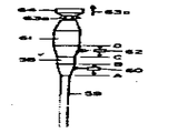
제 7 도는 광학 도파관 예형의 성형에 사용된 본 발명에 따른 장치를 도시한 도면.7 shows an apparatus according to the invention for use in shaping an optical waveguide preform.
* 도면의 주요부분에 대한 부호의 설명* Explanation of symbols for main parts of the drawings
10 : 맨드릴 12 : 척크(chuck)10 mandrel 12 chuck
14 : 인발 메카니즘 16 : 버너14: drawing mechanism 16: burner
20 및 34 : 미립자 물질 32 : 수으트(soot) 증착장치20 and 34: particulate matter 32: soot deposition apparatus
본 발명은 광학 도파관 섬유의 제조 방법에 관한 것이다.The present invention relates to a method for producing optical waveguide fibers.
광학 도파관 섬유는 지난 10년동안 크게 개량되었다. 손실이 매우 낮은 섬유는, 매우 순수한 물질을 성형시키는 화학적 증착법(CVD)에 의해 성형되는 것이 일반적이다. 이 방법에 따르면, 일시적 맨드릴의 외측면에, 또는 관(이 관은 후에 피복물질의 적어도 일부를 형성하게 된다)의 내측면상에 유리층을 증착시키거나, 또는 이들 기술을 결합시킴으로써 광학 도파관이 예형(preform)을 성형할 수 있다. 이러한 2가지 CVD방법의 구체적인 예에 대해서 이하에 간단히 설명하겠다.Optical waveguide fibers have been greatly improved over the last decade. Very low loss fibers are usually molded by chemical vapor deposition (CVD), which forms very pure materials. According to this method, an optical waveguide is preformed by depositing a glass layer on the outer side of the temporary mandrel, or on the inner side of the tube (which will later form at least part of the coating material), or by combining these techniques. (preform) can be molded. Specific examples of these two CVD methods will be briefly described below.
내부 증기상 산화법이라고 불리는 CVD방법의 한가지 예에 따르면, 반응물 증기를 산화 매질과 함께 중공(中空)의 원통형 기질을 통해 유동시킨다. 기질 및 함유된 증기 혼합물을 기질에 대하여 길이방향으로 이동하는 열원에 의해 가열하여서, 이동하는 가열지역의 기질관내에 설정되도록 한다. 가열지역내에 생긴 미립자 물질의 부유물을 하향 이동시켜서 이것의 적어도 일부가 기질의 내부표면위에 얹혀지도록 하고, 이것을 용융시켜서 연속적인 유리형 증착물을 형성시킨다. 최종적인 광학 도파관 섬유의 피복 및 코어 물질로서의 역할을 하는 적당한 층을 증착시킨 후에, 유리관의 온도를 일반적으로 증가시켜서 이 관이 붕괴되도록 한다. 그후 이때 형성된 인발 블랭크(draw blank)를 공지 기술에 따라 인발(引拔)하여서, 바람직한 직경을 가진 광학 도파관 섬유를 형성하는 것이다.According to one example of a CVD method called internal vapor phase oxidation, the reactant vapor is flowed through a hollow cylindrical substrate with an oxidation medium. The substrate and the vapor mixture contained therein are heated by a heat source moving longitudinally relative to the substrate so as to be set in the substrate tube of the moving heating zone. The suspension of particulate matter generated in the heating zone is moved downward so that at least a portion of it is placed on the inner surface of the substrate and melted to form a continuous glassy deposit. After depositing a suitable layer that serves as the core material and coating of the final optical waveguide fibers, the temperature of the glass tube is generally increased to cause the tube to collapse. The draw blanks formed at this time are then drawn in accordance with known techniques to form optical waveguide fibers having the desired diameter.
CVD방법의 다른 예에서는, 반응물 성분의 증기를 불꽃속으로 도입하여 산화시켜서, 유리 미립자 물질 또는 수우트(soot)를 형성시키고, 이를 맨드릴로 보낸다. 이와 같이 유리 수우트의 피막을 형성하는 소위 불꽃가수분해법 또는 외부 증기상 산화법은 미합중국 특허 제3,737,292호, 제3,823,995호, 제3,884,550호, 제3,957,474호 및 제4,135,901호에 상세하게 기재되어 있다. 스텝형 광학 도파관의 섬유를 형성하기 위해서는, 제 1 피막보다 낮은 굴절률을 갖는 제 2 피막을 제 1 피막의 외주면상에 가하여준다. 그래디언트형 광섬유를 형성하기 위해서는, 미합중국 특허 제3,823,995호에 기재된 바와 같이 굴절률이 점점 낮아지도록 되어 있는 다수의 층을 출발부재에 가하여준다. 그래디언트형 광섬유에는 피복 물질의 피막이 제공될 수도 있다. 다수의 피막이 맨드릴위에 형성된 후에, 맨드릴을 제거하고 이때 형성된 관상의 예형을 압밀로(consolidation furnace)내에 점차로 삽입한다. 압밀로의 온도는 유리 수우트 입자를 용융시키기에 충분할 정도로 높으므로, 수우트 예형은 입자 경계가 존재하지 않는 조밀한 유리 본체로 압밀된다. 미합중국 특허 제3,957,474호에 기재된 외부 증기상 산화법의 한가지 실시예에서는, 출발 로드(rod)가 최종적인 섬유의 코어를 형성한다. 증착된 피복 수으트는 코어 로드의 표면에 압밀되며, 이와 같이 압밀된 블랭크를 광학 도파관 섬유로 인발하는 것이다.In another example of the CVD method, the vapor of the reactant component is introduced into the flame and oxidized to form free particulate material or soot, which is sent to the mandrel. The so-called flame hydrolysis or external vapor phase oxidation method of forming a coating of glass soot is described in detail in US Pat. Nos. 3,737,292, 3,823,995, 3,884,550, 3,957,474 and 4,135,901. In order to form a fiber of a stepped optical waveguide, a second film having a refractive index lower than that of the first film is applied on the outer circumferential surface of the first film. To form a gradient optical fiber, a plurality of layers are applied to the starting member, the refractive index of which is gradually reduced as described in US Pat. No. 3,823,995. The gradient optical fiber may be provided with a coating of coating material. After a number of coatings have been formed on the mandrel, the mandrel is removed and the tubular preform formed at this time is gradually inserted into the consolidation furnace. Since the temperature of the compaction furnace is high enough to melt the glass soot particles, the soot preform is consolidated into a dense glass body without particle boundaries. In one embodiment of the external vapor phase oxidation process described in US Pat. No. 3,957,474, the starting rod forms the core of the final fiber. The deposited coating soot is compacted on the surface of the core rod and draws the compacted blank into optical waveguide fibers.
광학 도파관 예형을 형성하는 CVD방법에 의하면 매우 낮은 감쇠도를 갖는 광학 도파관 섬유를 형성할 수 있는 있지만, 이 섬유는 비교적 값이 비싸다. 또한, 내부 증기상 산화법에 의해 형성될 수 있는 예형의 크기는 비교적 제한된다. 중공의 원통형 기질관의 길이는, 반응 온도로 가열될 수 있으면서도 2개의 분리된 척크(chuck)사이에 지지될 수 있는 길이로 제한된다. 이 방법에서는, 기질관의 직경도 역시 제한된다.Although the CVD method for forming the optical waveguide preform can form an optical waveguide fiber having a very low degree of attenuation, this fiber is relatively expensive. In addition, the size of the preform that can be formed by the internal vapor phase oxidation method is relatively limited. The length of the hollow cylindrical matrix tube is limited to the length that can be heated to the reaction temperature while still being supported between two separate chucks. In this method, the diameter of the substrate tube is also limited.
예형의 크기를 증가시키거나 또는 예형이 형성되는 동안에 이 예형으로부터 섬유를 연속적으로 인발하면, 섬유의 제조가격을 낮출 수가 있다. 이들 2가지의 경비 절감 방법에 의하면, 섬유의 단위 길이에 대한 예형의 취급 및 처리단계의 수효가 감소된다.Increasing the size of the preform or continuously drawing fibers from the preform while the preform is being formed can lower the manufacturing cost of the fiber. According to these two cost saving methods, the number of pretreatment handling and processing steps for the unit length of the fiber is reduced.
외부 증기상 산화법은 경비 절감을 위해 쉽게 변형될 수가 있다. 초기에는, 예형의 직경을 크게함으로써 예형이 크게 만들어졌다. 이것은, 버너를 수우트 예형을 따라 길이방향으로 횡단시킨 다음, 반경을 증가시키는 부가적인 층을 여기에 추가시킴으로써 이루어졌었다. 그후에, 한개 혹은 다수의 버너 또는 기타의 수우트 증착 노즐을 출발부재를 향해 축방향으로 배향시키는 축 방법이 개발되었다. 증착된 수우트층의 두께가 증가됨에 따라서, 출발 부재는 버너로 부터 멀리 이동된다. 축방향 증기상 산화법은 미합중국 특허 제3,966,446호, 제4,017,288호, 제4,135,901호, 제4,224,046호 및 4,231,774호에 기재되어 있다.External vapor phase oxidation can be easily modified to reduce costs. Initially, the preform was made large by increasing the diameter of the preform. This was done by longitudinally traversing the burner along the soot preform and then adding additional layers to it to increase the radius. Subsequently, an axial method was developed in which one or more burners or other soot deposition nozzles were axially oriented towards the starting member. As the thickness of the deposited soot layer is increased, the starting member is moved away from the burner. Axial vapor phase oxidation processes are described in US Pat. Nos. 3,966,446, 4,017,288, 4,135,901, 4,224,046, and 4,231,774.
축방향 증기상 산화법에 의해 코어를 형성하고, 방사상 내향을 향하는 유리 수우트의 흐름에 의해 피복층을 코어에 동시에 증착시키는 혼합 방법은 미합중국 특허 제3,957,474호와 제4,062,655호에 기재되어 있다. 코어가 형성되면, 이 코어는 이것을 형성하였던 버너 또는 노즐로 부터 회수된다. 피복은 고정된 버너 또는 노즐에 의해 증착된다.Mixing methods are described in US Pat. Nos. 3,957,474 and 4,062,655, which form cores by axial vapor phase oxidation and simultaneously deposit coating layers on cores by flow of radially inward glass soot. Once the core is formed, it is recovered from the burner or nozzle that formed it. The coating is deposited by a fixed burner or nozzle.
증기상 산화법에 의해 광학 도파관 섬유를 형성하는 연속적인 방법은 슐츠(P.C. Schultz)에게 허여된 미합중국 특허 제4,230,472호, 영국 특허원 제2,023,127A호 및 브랭큰쉽(M.G. Blankenship)의 명의로 1980년 6월 2일자 출원된 미합중국 특허원 제155,422호에 기재되어 있다.A continuous method of forming optical waveguide fibers by vapor phase oxidation is described in June 1980 under the names of U.S. Patent Nos. 4,230,472, 2,023,127A and MG Blankenship to PC Schultz. US Patent Application No. 155,422, filed on Feb. 2.
슐츠의 특허에 따르면, 연속적인 코어 부재를 길이방향으로 이동시키면서 미립자 물질의 접착성 피막을 여기에 동시에 기하여줌으로써, 균일한 두께의 연속적이고 균질한 점착성 피막을 형성시킨다. 이와 같이 형성된 복합체를 동시에 또는 차후에 가열함으로써 점착성 피막을 소결 또는 압밀시켜서 고체 블랭크를 형성시키고, 이 고체 블랭크를 이 물질의 인발온도로 가열하고 인발하여서 단면적을 감소시키면, 실질적으로 연속적인 광학 도파관의 형성된다. 코어 부재는 코어를 구성하고, 압밀된 피막은 최종적인 광학 도파관의 피복을 구성한다. 점착성 피막을 소결 또는 압밀시켜서 고체 블랭크를 형성한 다음에 별도의 공정에서 인발할 수도 있고, 또는 연속 공정의 일부로서 차후에 인발할 수도 있다. 다른 방법으로서는, 구조물을 1회 가열시키는 방법을 사용하는 소결 또는 압밀단계의 직후에 광학 도파관을 인발할 수도 있다.According to Schulz's patent, the adhesive coating of particulate matter is simultaneously based on this while moving the continuous core member in the longitudinal direction, thereby forming a continuous and homogeneous adhesive coating of uniform thickness. The composite thus formed is sintered or consolidated by simultaneously or subsequent heating to form a solid blank, which is heated to draw temperature of this material and drawn to reduce the cross-sectional area, thereby forming a substantially continuous optical waveguide. do. The core member constitutes a core and the consolidated coating constitutes the final coating of the optical waveguide. The adhesive coating may be sintered or consolidated to form a solid blank and then drawn off in a separate process, or may be subsequently drawn off as part of a continuous process. Alternatively, the optical waveguide may be drawn immediately after the sintering or consolidation step using the method of heating the structure once.
영국 특허원 제2,023,127A호에 따르면, 나(裸) 섬유 코어를 가열된 유리 로드로 부터 인발한다. 유리 미립자를 증착시킴에 의해 코어 섬유상에 피복을 형성하고, 그후에 이를 가열함으로써 압밀된 유리 피복을 형성시킨다.According to British Patent No. 2,023,127A, bare fiber cores are drawn from a heated glass rod. The coating is formed on the core fibers by depositing the glass fine particles, which are then heated to form a compacted glass coating.
브랭큰쉽의 특허 출원서에는, 광학 도파관 예형에 적합한 물품을 형성하는 연속적인 방법에 대해서 기재되어 있다. 출발부재 또는 유인판(bait)을 준비하고 출발 부재의 외면에 미립자 물질을 가하여 피막을 형성시킴으로써, 예형을 형성한다. 피막을 길이 방향으로 이동시키면서 이와 동시에 부가적인 미립자 물질을 피막에 가하여 예형 본체를 형성시키고, 그후 이 예형 본체를 길이방향으로 이동시킨다. 예형 본체를 길이방향으로 이동시키고 그 단부에 부가적인 미립자 물질을 가하여 주는 동안, 출발 부재를 예형 본체로부터 연속적으로 제거하여서 예형 본체내의 길이방향의 구멍을 남겨 놓는다. 이렇게 형성된 예형을 그 후에 가열 및 압밀하고 인발하면, 광학 도파관 섬유가 얻어진다.The Blankenship patent application describes a continuous method of forming an article suitable for optical waveguide preforms. A preform is formed by preparing a starting member or bait and adding a particulate material to the outer surface of the starting member to form a film. At the same time additional particulate material is added to the coating to move the coating in the longitudinal direction to form a preform body, which is then moved in the longitudinal direction. While the preform body is moved longitudinally and additional particulate material is applied at its ends, the starting member is continuously removed from the preform body, leaving a longitudinal hole in the preform body. The preform thus formed is then heated, compacted and drawn to obtain an optical waveguide fiber.
상술한 바와 같은 CVD 방법에서 증착 속도를 결정하는 중요하고 제한적인 요소는, 수우트 입자가 실려지는 가스 흐름의 온도에 관련된다. 심킨스(P.G. Simkins) 등에 의한 “열 편승(Thermophoresis) : 변형된 화학적 증착에 있어서의 대량 이송 매카니즘”[저어널 오브 어플라이드 피직스(Journal of Applied Physics), 제50권 제 9 호(1979년 9월) 5676-5681면]을 참조하기 바란다. 열 편승은 수우트 입자들을 가스 흐름의 고온부분으로부터 저온 부분을 향해 구동시킨다. 예형의 표면은 이를 둘러싸고 있는 가스 흐름보다 통상적으로 저온이기 때문에, 수우트 입자들은 열 편승의 작용에 의하여 예형 표면을 행해 구동된다. 예형 표면의 온도와 이를 둘러싸고 있는 가스 흐름의 온도가 거의 같으면, 온도 구배가 낮아진다. 그러므로, 열 편승 효과는 최소로 되고, 증착 속도도 느려진다. 그러나, 예형의 표면 온도가 낮으면, 커다란 열 구배로 인한 열 편승 효과에 의하여 증착 속도가 비교적 빠르게 된다.An important and limiting factor in determining the deposition rate in a CVD method as described above is related to the temperature of the gas flow on which the soot particles are loaded. “Thermophoresis: Mass Transfer Mechanism in Modified Chemical Deposition” by PG Simkins et al. [Journal of Applied Physics, Vol. 50, No. 9, September 1979]. ), Pp. 5676-5681. Thermal piggyback drives the soot particles from the hot portion of the gas stream toward the cold portion. Since the surface of the preform is typically colder than the gas flow surrounding it, the soot particles are driven through the preform surface by the action of thermal piggybacking. If the temperature of the preform surface is approximately equal to the temperature of the gas flow surrounding it, the temperature gradient is lowered. Therefore, the heat piggyback effect is minimized and the deposition rate is also slowed. However, if the surface temperature of the preform is low, the deposition rate is relatively high due to the heat piggybacking effect due to the large thermal gradient.
상술한 바와 같은 종래 기술에서, 버너는 예형위의 하나의 위치를 연속적으로 향하게 된다. 그러므로, 예형 표면이 가열되고, 이 예형 표면과 수우트 함유 가스 흐름 사이의 작은 온도 구배에 의하여 증착 속도가 제한된다.In the prior art as described above, the burner is continuously directed at one position on the preform. Therefore, the preform surface is heated and the deposition rate is limited by the small temperature gradient between the preform surface and the soot containing gas flow.
따라서, 본 발명의 목적은 광학 도파관 섬유를 제조하기 위한 증기상 산화법의 증착 효율을 개량하려는 것이다.Accordingly, it is an object of the present invention to improve the deposition efficiency of vapor phase oxidation for the production of optical waveguide fibers.
간단하게 말하면, 본 발명의 방법은 다음과 같다. 버너 등의 수단에 의해 유리 미립자 물질의 흐름을 원통형 코어 부재의 측방향 표면으로부터 보내어 줌으로써, 이 표면에 제 1 피막을 형성시킨다. 코어 부재를 회전운동시키고, 또한 버너에 대해 한쪽 방향으로 길이방향으로 운동시킨다. 또한, 버너를 코어 부재의 길이방향의 일부분에 대하여 진동시킨다. 코어 물질에 대한 버너는 길이방향 운동 및 진동 운동이 결합되면 코어 물질의 일부에 미립자 물질이 소정의 두께로 쌓여지는데, 이 미립자 물질의 두께는 상술한 소정의 두께로부터 점점 가늘어져서, 코어 물질에 대한 버너의 전동 운동이 일어나는 지역에서는 그 두께가 0의 값에 수렴하게 된다. 코어 물질에 대한 버너의 진동 운동에 의하면 버너가 연속적으로 통과하는 사이에 수우트 예형이 냉각되므로 열 편승이 향상되어서 증착 속도가 증가하게 된다. 버너와 코어 물질 사이의 연속적인 길이방향 운동에 의하면 비교적 긴 예형이 형성되거나 예형이 연속적으로 제조될 수 있으므로, 필요에 따라서 섬유를 이로부터 연속적으로 인발해 낼 수 있다.In short, the method of the present invention is as follows. By sending a flow of the glass particulate matter from the lateral surface of the cylindrical core member by means of a burner or the like, a first film is formed on this surface. The core member is rotated and also longitudinally moved in one direction with respect to the burner. The burner is also vibrated with respect to a portion of the core member in the longitudinal direction. The burner for the core material combines longitudinal and vibrational motion to build up a portion of the core material in a predetermined thickness, the thickness of which is tapered from the predetermined thickness described above, In areas where the burner's motor movement occurs, the thickness converges to a value of zero. The vibratory motion of the burner relative to the core material cools down the soot preforms between successive passages of the burner, thereby improving thermal transfer and thus increasing deposition rate. The continuous longitudinal motion between the burner and the core material allows a relatively long preform to be formed or the preform can be produced continuously, thereby allowing the fiber to be drawn continuously therefrom as needed.
이하, 첨부도면을 참조하면서 본 발명을 더욱 구체적으로 설명하면 다음과 같다.Hereinafter, the present invention will be described in more detail with reference to the accompanying drawings.
제 1 도에서, 실리카 또는 그외의 다른 고온 내화성 물질로 된 맨드릴(10)은 척크(12)에 고정되어 있으며, 이 척크(12)는 화살표(14a) (14b)로 각각 표시된 바와 같이 메카니즘(14)에 의해 회전하거나 길이방향 축을 따라 이동한다. 맨드릴(10)은 처음에 예컨대 불꽃 가수분해 버너(16)과 같은 축방향 수우트 증착 수단의 부근에 배치되므로 그 단부면은 버너로부터 방출되는 미세한 수우트 입자의 경로내에 있게 된다. 최종적인 예형의 코어 부분(22)를 형성하게 될 미립자 물질의 점착성 피막은 처음에 맨드릴의 단부면에 배치된다. 미립자 물질(20)은 광학 도파관의 코어에 적합한 임의의 물질이어도 좋지만, 도파관 피복의 굴절률보다 높은 굴절률을 가져야 한다. 증착 수단(16)에 구성 성분을 전달하기에 적합한 수단은, 예컨대 미합중국 특허 제3,826,560호, 제1,148,621호 및 제4,173,304호 등에 기재된 바와 같은 공지된 임의의 수단일 수 있다.In FIG. 1, the mandrel 10 of silica or other high temperature refractory material is fixed to the chuck 12, which is the mechanism 14 as indicated by arrows 14a and 14b, respectively. Rotate or move along the longitudinal axis. The mandrel 10 is initially placed in the vicinity of an axial soot deposition means such as, for example, a flame hydrolysis burner 16 so that its end face is in the path of fine soot particles emitted from the burner. A tacky coating of particulate material that will form the
미립자 물질이 맨드릴의 단부면에 증착되고 이러한 증착이 계속되면, 다공성(porous)의 예형 코어 부분이 형성된다. “다공성 예형”이란, 유리 또는 증착되는 물질의 작은 입자들이 서로 부착되어서 그 사이에 약간의 공간이 형성되는 비교적 다공성의 본체를 의미한다. 단부면(24)는 미립자 물질의 증착에 의해 연속적으로 새롭게 형성된다. 증착 수단(16)은 길이방향 이동에 관한 한도내에서는 실제적으로 고정되어 있기 때문에, 출력 부재(10)은 단부면(24) 위에 미립자 물질이 쌓여지는 속도에 대응하는 속도로 화살표(14b)의 방향으로 그 길이방향 축을 따라 이동함으로써 단부면(24)가 증착 수단(16)으로부터 비교적 고정된 거리에 있도록 하여 주는 것이 바람직하다. 이러한 고정된 거리를 유지하기 위해서는, 미합중국 특허 제4,062,665호의 제 8 도에 도시된 것과 같은 수단을 사용하여도 좋다.When particulate material is deposited on the end face of the mandrel and this deposition continues, a porous preformed core portion is formed. By “porous preform” is meant a relatively porous body in which small particles of glass or deposited material adhere to one another and form some space therebetween. The end face 24 is continuously newly formed by the deposition of particulate material. Since the deposition means 16 are practically fixed within the limits of the longitudinal movement, the output member 10 is directed in the direction of the arrow 14b at a rate corresponding to the rate at which particulate matter is deposited on the end face 24. The end face 24 is preferably kept at a relatively fixed distance from the vapor deposition means 16 by moving along its longitudinal axis. In order to maintain such a fixed distance, a means such as that shown in FIG. 8 of US Pat. No. 4,062,665 may be used.
수우트 증착 수단(16)은, 코어 부재로 향할 수 있는 미립자 물질의 흐름을 제공하는 평면 버너, 리본 버너, 링 버너 등을 비롯한 임의의 수우트 증착용 버너로 구성될 수 있다. 적당한 버너의 예는 미합중국 특허 제3,563,345호와 제1,165,223호에 기재되어 있다. 또한, 증착 수단(16)은 레이저 비임과 같은 수단에 의해 가열되어서 수우트 흐름을 형성하게 되는 반응물 증기를 방출하는 미합중국 특허 제3,957,474호에 기재된 것과 같은 노즐로 구성될 수 있다. 수우트 증착용 버너가 바람직하기 때문에, 이하에서는 이러한 형태의 수우트 증착 수단에 관련하여 설명하기로 한다.The soot deposition means 16 may be comprised of any soot deposition burner, including planar burners, ribbon burners, ring burners, and the like, which provide a flow of particulate material that may be directed to the core member. Examples of suitable burners are described in US Pat. Nos. 3,563,345 and 1,165,223. The deposition means 16 may also consist of a nozzle as described in US Pat. No. 3,957,474, which emits a reactant vapor that is heated by means such as a laser beam to form a soot stream. Since a burner for soot deposition is preferred, the following description will be made with respect to this type of soot deposition means.
본 발명에서는, 버너가 단부면(24)의 주위에서 회전하도록 되어 있다. 버너의 회전은 출발 부재(12)의 회전에 부가하여서, 또는 그 대신에, 또는 출발 부재의 회전과의 임의의 결합에 의하여 이루어질 수 있다. 축방향 증기상 산화법에 의해 다공성 예형 코어 부분을 혀성하기에 적합한 다른 수단들은, 예를 들어 상술한 미합중국 특허 제3,957,474호, 제3,966,446호, 제4,062,665호, 제4,017,228호 및 제4,224,046호에 기재되어 있다.In the present invention, the burner is configured to rotate around the end face 24. Rotation of the burner may be in addition to, or instead of, the rotation of the starting member 12, or by any combination with the rotation of the starting member. Other means suitable for tongue forming a porous preformed core portion by axial vapor phase oxidation are described, for example, in US Pat. Nos. 3,957,474, 3,966,446, 4,062,665, 4,017,228 and 4,224,046 described above. .
최종적인 예형의 피복(30)을 형성하게 될 미립자 물질의 점착성 피막은 수우트 증착 수단(32)에 의해 증착된다. 이 수우트 증착 수단(32)도 역시 버너, 노즐등으로 구성될 수 있다. 버너(32)는 코어 부분(22)의 주위에 배치된 다수의 버너로 구성될 수 있고, 이 버너들은 예형 축의 주위에서 회전할 수 있다. 바람직한 실시예에서는, 버너(16) (32)가 예형 축의 주위를 회전하는 것이 아니라, 예형이 형성될 때에 이 예형의 화살표(14a)의 방향으로 회전한다. 미립자 물질(34)는 광학 도파관 섬유의 피복에 적합한 임의의 물질일 수 있는데, 이것의 특징은 광학적인 순도 및 코어 물질의 굴절률보다 낮은 굴절률이다.An adhesive film of particulate material that will form the
본 발명에 따르면, 버너(32)는 예형의 길이방향 축을 따라 앞뒤로 이동하다. 버너(32)의 이러한 진동 운동은 인발 메카니즘(14)에 의한 화살표(14b)의 방향으로의 맨드릴(10)의 이동에 의해 야기되는 예형에 대한 이 버너의 균일한 상대적인 운동에 중첩된다. 그 결과, 피복이 증착되는 초기에 원추형 지역(36)이 형성되며, 버너(32)가 피복 수우트를 증착하는 피복(30)의 부분에는 원추형 지역(38)이 형성된다. 버너(32)의 진동 운동이 없으면, 코어 부분(22)과 피복 부분(30)의 외면 사이의 테이퍼 된 지역의 세로 길이는 버너에 의해 발생된 수우트 흐름의 폭에 의해 결정된다.According to the invention, the burner 32 moves back and forth along the longitudinal axis of the preform. This vibratory motion of the burner 32 is superimposed on the uniform relative motion of this burner relative to the preform caused by the movement of the mandrel 10 in the direction of the arrow 14b by the drawing mechanism 14. As a result, a conical region 36 is formed early in the coating deposition, and a conical region 38 is formed in the portion of the
코어 부분(22)를 따른 버너(32)의 길이방향 진동은 수우트 증착 속도를 증가시킨다. 상술한 바와 같이, 열편승 힘은 버너에 의해 방출된 고온 가스로부터의 수우트 입자들을 저온의 예형 표면을 향해 구동시킨다. 버너(32)가 종래의 기술에서와 같이 고정 상태로 유지되면, 수우트 흐름은 수우트가 방금 증착되었던 예형의 비교적 고온 지역으로 연속적으로 보내어지게 될 것이다. 이 상태에서, 버너에 의해 방출되는 수우트는 이 수우트가 향하게 되는 예형 지역으로 강하게 유인되지는 않는다. 그러므로, 방출된 수우트의 많은 부분은 원래의 경로로부터 벗어나서 예형 위에 증착되지 못하게 된다. 그러나, 본 발명에서는, 버너(32)가 예형의 축을 따라 앞뒤로 진동하기 때문에, 버너에 의해 방출되는 수우트 입자는 예형의 비교적 저온 부분을 향하게 된다. 그러므로, 수우트 입자에 작용하는 열 편승 힘은 더욱 커지게 되어서, 증착 효율이 증가하는 것이다.The longitudinal vibration of the burner 32 along the
제 2 도에 도시된 바와 같이, 이 장치는 미립자 물질의 또 하나의 층(45)를 형성하기 위한 부가적인 버너(44)를 갖출 수도 있다. 이 도면에서, 제 1 도에서와 유사한 소자들은 동일한 참조부호에 프라임(')을 붙여서 표시하였다. 예형의 축을 길이방향으로 따르는 버너(44)의 진동 운동은 원추형의 테이퍼 지역(46)을 형성한다. 버너(44)에 의해 증착되는 수우트(48)는 수우트(34')와 동일한 조성을 갖는 것일 수도 있고 상이한 조성을 갖는 것일 수도 있다.As shown in FIG. 2, the apparatus may be equipped with an additional burner 44 for forming another layer 45 of particulate material. In this figure, elements similar to those in FIG. 1 are denoted with the same reference numerals ('). The vibratory motion of the burner 44 along the axis of the preform longitudinally forms a conical tapered area 46. The soot 48 deposited by the burner 44 may have the same composition as the soot 34 'or may have a different composition.
제 2 도에 도시된 반응물 전달 시스템은 미합중국 특허 제4,173,305호에 기재된 것이다. SiCl4공급원(49)는 계량 펌프(50)을 거쳐서 혼합 장치(51)에 접속된다. GeCl4공급원(52)는 계량 펌프(53)을 거쳐서 혼합 장치(51)에 접속된다. 혼합 장치의 상세한 설명에 대하여서는, 미합중국 특허 제4,173,305호를 참조하기 바란다. 펌프(50) (53)을 통해 흐르는 반응물의 양은 유량 제어기(54)에 의해 제어된다. 산소는 질량 제어기(55)에 의해 혼합 장치(51)에 공급된다.The reactant delivery system shown in FIG. 2 is described in US Pat. No. 4,173,305. SiCl 4 source 49 is connected to mixing
비교적 직경이 작은 코어 부분을 갖는 단일 모우드 광학 도파관 예형을 형성하기 위해서는 예를 들어, GeO2첨가된 SiO2코어를 버너(16')에 의해 형성되는 한편, 순수한 SiO2로 구성된 피복 수우트의 층을 버너(32')(44)에 의해 증착될 수도 있다.In order to form a single mode optical waveguide preform having a relatively small core portion, for example, a layer of coating suit composed of pure SiO 2 , while a GeO 2 added SiO 2 core is formed by the burner 16 ′ May be deposited by the burners 32'44.
상술한 단일 모우드 섬유 예형에 비해 코어 부분의 직경이 비교적 큰 스텝형 섬유의 예형을 형성하기 위해서는, 버너(16' (32')는 동일한 조성을 갖는 코어 유리 수우트를 증착할 수 있고, 버너(44)는 피복 수우트의 피막을 만들 수 있다.To form a preform of stepped fibers having a relatively large diameter of the core portion compared to the single mode fiber preform described above, the burners 16 '32' can deposit core glass suits having the same composition and burner 44 ) Can make a coating suit.
그래디언트형 섬유 예형을 형성하기 위해서는, 버너(32')로 공급되는 반응물 증기의 조성을 이 버너의 위치에 따라 변화시킬 수 있다. 유량 제어기(54)와 버너(32')를 연결하는 점선(56)은, 버너(32')의 위치를 나타내는 신호가 이 유량 제어기(54)에 제공된다는 사실을 나타내는 것이다. 이러한 실시예에서, 버너(16')는 예형코어의 중심부를 형성하는 수우트(20')를 만든다. 예를 들어, 수우트(20')는 예컨대 GeO2와 같은 1종류 이상의 첨가제 산화물이 첨가된 SiO2로 구성될 수도 있다. 버너(32')는 예형 코어의 나머지 부분을 형성한다. 따라서, 이 버너(32')가 그 진동 우동시에 위치(A0에 도달하면 최대량의 첨가제 산화물을 포함하는 수우트 흐름이 발생되며, 버너(32')가 위치(B0에 도달하면 다소 적은 양의 첨가제 물질을 포함하는 수우트 흐름이 발생된다. 이러한 사실은, 예를 들어 제 3 도의 그래프에 도시된 방법으로 버너의 위치에 따라 계량 펌프(53)을 통과하는 GeCl4의 유량을 변화시키는 한편, 계량 펌프(50)을 통과하는 SiCl4의 유량을 일정하게 유지시킴으로써 이루어질 수 있다. 수우트(34')내의 최대의 첨가제 농도는 수우트(20')의 경우에 비하여 약간 적어야 한다.To form a gradient fiber preform, the composition of the reactant vapor supplied to burner 32 'can be varied depending on the position of this burner. The dashed line 56 connecting the flow controller 54 and the burner 32 'indicates that a signal indicating the position of the burner 32' is provided to this flow controller 54. In this embodiment, burner 16 'produces a suit 20' that forms the center of the preform core. For example, the soot 20 'may be composed of SiO 2 to which one or more additive oxides such as GeO 2 are added. Burner 32 'forms the remainder of the preform core. Thus, when this burner 32 'reaches the position A0 at its oscillating utop, a soot stream containing the maximum amount of additive oxide is generated, and when burner 32' reaches the position B0, a rather small amount of additive A soot stream comprising material is generated, which changes the flow rate of GeCl 4 through the metering pump 53 according to the position of the burner, for example in the manner shown in the graph of FIG. This can be achieved by maintaining a constant flow rate of SiCl 4 through the
제 4 도의 실시예에서, 수우트의 피막(58)은 버너(60)에 의해 맨드릴(59) 위에 증착되고, 피막(61)은 버너(62)에 의해 피막(58)의 표면위에 증착된다. 이 분야에 공지된 바와 같이, 맨드릴(59)는 증착되는 물질과 양립할 수 있는 팽창계수를 가진 유리, 세라믹 등과 같은 물질로 형성될 수 있다. 맨드릴(59)는 척크(64)에 의해 화살표(63a) (63b)로 표시한 바와 같이 회전되고 길이방향으로 이동된다. 버너(60)은 위치(A)와 위치(B)의 사이에서 진동하고, 버너(62)는 위치(C)와 위치(D)의 사이에서 진동한다. 다공성 예형을 압밀하기 전에 맨드릴(59)를 예형으로부터 제거하려고 할 때에는, 미합중국 특허 제4,233,052호에 기재된 바와 같이, 유리 수우트를 맨드릴 표면에 증착하기 전에 이 맨드릴 표면을 탄소 수우트 층으로 피복할 수도 있다.In the embodiment of FIG. 4, the coating 58 of the suit is deposited on the mandrel 59 by burners 60, and the coating 61 is deposited on the surface of the coating 58 by burners 62. As is known in the art, the mandrel 59 may be formed of a material such as glass, ceramic, or the like, having an expansion coefficient compatible with the material being deposited. The mandrel 59 is rotated and longitudinally moved as indicated by arrows 63a and 63b by the chuck 64. Burner 60 vibrates between position A and position B, and burner 62 vibrates between position C and position D. FIG. When attempting to remove the mandrel 59 from the preform before consolidating the porous preform, the mandrel surface may be coated with a layer of carbon soot prior to depositing the glass suit on the mandrel surface, as described in US Pat. No. 4,233,052. have.
맨드릴(59)는 광학 도파관 섬유의 코어 부분으로서 사용되기에 적합한 굴절률을 갖고 있는 고순도 유리 로드로 구성될 수 있다. 예를 들어, 이 로드는 일정한 기울기로 변하는 굴절률을 가질 수도 있고 균일한 굴절률을 가질 수도 있다. 이러한 실시예에서, 코어 유리보다 낮은 굴절률을 가진 하나 또는 그 이상의 피복 유리 수우트층을 코어 유리 로드위에 증착시킨 후에 압밀시켜서, 광학 도파관 섬유를 인발하기에 적합한 고체의 유리 인발 블랭크를 형성할 수도 있다.The mandrel 59 may be composed of a high purity glass rod having a refractive index suitable for use as the core portion of the optical waveguide fiber. For example, the rod may have a refractive index that varies with a constant slope and may have a uniform refractive index. In such embodiments, one or more coated glass soot layers having a lower refractive index than the core glass may be deposited on the core glass rod and then consolidated to form a solid glass drawing blank suitable for drawing optical waveguide fibers. .
상술한 방법에 따라 제조되는 예형이 적당한 길이로 되면, 이들 예형을 증착 장치로부터 제거되는 압밀로로 이송하며, 이들 예형은 압밀로내에서 유리 수우트 입자를 압밀하기에 충분히 높은 온도로 가열됨으로써, 고체의 유리 광학 도파관 인반 블랭크가 형성된다. 그러나, 이 공정이 광학 도파관 섬유를 연속적으로 제조하기 위한 것이라면, 제 5 도에 도시된 것과 같은 장치가 사용될 수도 있다. 이 장치는 미합중국 특허 제4,230,472호 및 제1980년 6월 2일자로 “연속적으로 제거할 수 있는 출발 부재를 가진 광학 도파관 예형의 성형 방법 및 장치”라는 명칭으로 출원된 미합중국 특허 제155,422호에 제시돈 것과 유사하다. 수우트 예형(67)은 수단(68)에 의해 지지되고 회전되는 한편, 리일(70)에 의해 화살표(69)의 방향으로 길이방향으로 이동된다. 수단(68)은, 예를 들어, 예형(67)을 둘러싸고 있고 구조물을 지지, 회전 및 이동시키도록 장착된 다수의 로울러로 구성될 수도 있다. 이러한 지지 로울러 수단은 이 분야에 공지되어 있다. 히터(71)은, 다공성 예형을 고체의 유리 로드(72)로 압밀시키기에 충분한 온도로 이 다공성 예형을 가열시킨다. 압밀된 로드는, 상술한 수단(68)과 유사한 수단(73)에 의해 지지되고 회전된다. 압밀된 로드(72)는 히터(74)들의 사이로 통과하며, 이때 이 로드의 온도는 그 재질의 인발 온도로 증가되어서, 광학 도파관 섬유(75)로 인발되어 리일(70)에 감겨진다. 이와 같이, 본 발명에 따라서 형성되는 예형은 동시에 섬유로 입발될 수 있는 것이다.Once the preforms produced according to the method described above have a suitable length, these preforms are transferred to a consolidation furnace which is removed from the deposition apparatus, and these preforms are heated to a temperature high enough to consolidate the glass soot particles in the consolidation furnace, A solid glass optical waveguide invan blank is formed. However, if this process is for producing optical waveguide fibers continuously, an apparatus such as that shown in FIG. 5 may be used. This device is disclosed in US Pat. No. 4,230,472 and in US Pat. No. 155,422 filed June 2, 1980 entitled “Method and Apparatus for Forming an Optical Waveguide Preform with a Removable Starting Member.” Similar to The suit preform 67 is supported and rotated by the means 68, while the
본 발명의 방법 및 장치에 의해 이루어진 증착 속도의 개선을 설명하기 위해 다음의 실험을 행하였다. 원통형 맨드릴을 선반내에 수평위치로 지지시켰다. 미합중국 특허 제4,165,223호에 기재된 형태의 버너를 한개 사용하였다. 내측 차단 및 외측 차단 산소 유속은 각각 35slm 및 10.0slm 이었다. 사용된 단지 하나의 반응물인 SiCl4를, 미합중국 특허 제3,826,560호에 기재된 형태의 저장소내에 37℃로 유지시켰다. 1.75slm의속도로 유출되는 산소는 액체 SiCl4를 통해 거품이 생기게 하였도, 약 1.75 ml의 속도로 유지시켰다. 1.75slm의 속도로 유출되는 간소와 SiCl4증기의 혼합물을 버너에 공급하였다. 버너의 표면은 맨들의 중심으로부터 약 120mm 덜어진 거리에 유지시켰다. 1개소(組)의 실험에서는 고정된 버너에 의해 실리카 수우트를 맨드릴상에 증착시킨다. 다른 조의 실험에서는, 그외의 모든 다른 상태를 동일하게 유지시키면서, 버너를 1.75cm/sec의 속도로 각각의 맨드릴 25cm 부분을 따라 앞뒤로 이동시킴으로써 실리카 수우트를 맨드릴상에 증착시켰다. 이러한 2개조의 실험에서, 수우트는 10분간 증착되었다. 2개의 상이한 형태의 맨드릴, 즉 비경이 51mm인 봉규산과과 직경이 19mm인 석영관이 사용되었다. 이와 같은 2가지의 크기의 맨드릴에 대해 여러가지의 회전 속도를 사용하였다. 수우트 증착 처리의 전후에 맨드릴을 메들리(Mettler) 개방식 팬 저울로 무게를 재었다.The following experiments were conducted to demonstrate the improvement in deposition rate achieved by the method and apparatus of the present invention. The cylindrical mandrel was supported in a horizontal position in the lathe. One burner of the type described in US Pat. No. 4,165,223 was used. Inner and outer barrier oxygen flow rates were 35 slm and 10.0 slm, respectively. Only one reactant used, SiCl 4 , was maintained at 37 ° C. in a reservoir of the type described in US Pat. No. 3,826,560. The outflowing oxygen at a rate of 1.75 slm bubbled through the liquid SiCl 4 , but was maintained at a rate of about 1.75 ml. A mixture of lean gas and SiCl 4 vapor effluent at a rate of 1.75 slm was fed to the burner. The burner surface was kept about 120 mm away from the center of the man. In one experiment, silica soot is deposited on the mandrel by means of a fixed burner. In another set of experiments, silica soot was deposited on the mandrel by moving the burner back and forth along each 25 cm portion of each mandrel at a rate of 1.75 cm / sec while keeping all other states the same. In this two set of experiments, the soot was deposited for 10 minutes. Two different types of mandrels were used: rod silicic acid having a diameter of 51 mm and quartz tube having a diameter of 19 mm. Various rotational speeds were used for these two sizes of mandrel. The mandrel was weighed with a Mettler open pan scale before and after the soot deposition process.
52mm관을 사용할 때에는, 연료가스(CH4)와 산소를 각각 11.0slm 및 11.2a의 속도로 버너에 유동시켰다. 이 관에 실리카 수우트를 증착하기 전에, 이 관을 버너에 의해 3분동안 예열시키서, 이 관의 표면이 안정된 온도로 되도록 하였다. 이 실험의 결과는 다음의 표 1에 나타나 있다.When using a 52 mm tube, fuel gas (CH 4 ) and oxygen were flowed into the burner at speeds of 11.0 slm and 11.2 a, respectively. Prior to depositing silica soot on this tube, the tube was preheated with a burner for 3 minutes to bring the surface of the tube to a stable temperature. The results of this experiment are shown in Table 1 below.
[표 1]TABLE 1

19mm의 유인관을 사용할 때에는, 관의 부피가 작기 때문에 단지 1분동안만 예열하였다. 또한, 버너로 향하는 연료 가스 및 산소의 유속을 표 2에 작성된 값에 따라 감소시켜서, 불꽃 온도를 감소시켰다. 주어진 맨드릴을 회전속도에 있어서, 연료 가수 및 산소의 유속은 버너가 이동하는 경우 및 고정된 경우의 각각의 시험에 있어서 모두 동일하였다.When using a 19 mm attraction tube, the tube was preheated for only 1 minute because of its small volume. In addition, the flow rates of fuel gas and oxygen directed to the burner were reduced in accordance with the values shown in Table 2, thereby reducing the flame temperature. In the rotational speed of a given mandrel, the flow rates of fuel gas and oxygen were the same for each test when the burner was moving and when it was fixed.
[표 2]TABLE 2
연료-산소 유속(sim)-19mm관Fuel-oxygen (sim) -19 mm tube

직경이 19mm인 관을 사용한 실험의 결과는 표 3에 나타나 있다.The results of the experiment using a 19 mm diameter tube are shown in Table 3.
[표 3]TABLE 3

고정 버너의 경우에 비하여, 이동 버너를 사용함으로써 얻어진 개선선율(%)는 표 1과 표 3에 나타나 있다. 맨드릴의 회전속도가 비교적 느릴 때에 가장 크게 개선된다. 그러므로, 본 발명의 방법과 장치에서 사용된 이동 버너에 의해 층을 증착할 때에는, 맨들링의 회전속도가 10 내지 50RPM 정도인 것이 바람직하다.Compared with the case of the fixed burner, the improvement rate (%) obtained by using a moving burner is shown in Table 1 and Table 3. The greatest improvement is achieved when the mandrel's rotation speed is relatively slow. Therefore, when depositing a layer by a moving burner used in the method and apparatus of the present invention, it is preferable that the rotation speed of the mandling is on the order of 10 to 50 RPM.
본 발명에 따라 스텝형 섬유를 제조하는 방법의 한가지 에를 다음과 같다. 제 6 도와 제 7 도에는 맨드릴(79)를 수직위치로 지지하기 위한 척크(78)이 도시되어 있다. 척크(78)은, 화살표(80a) (80b)로 표시된 바와 같이 맨드릴(79)를 회전시키고 동시에 수직 상향으로 이동시키는 인발 메카니즘에 연결되어 있다. 제6도는 예형(81)의 초기 성형시의되어서 성형시의 단면도이고, 제7도는 충분한 양의 예형(81)이 형성되어서 외부 피복의 표면(82)가 최종적인 직경에 도달하였을 때의 단면도이다.One example of a method for producing stepped fibers according to the present invention is as follows. 6 and 7 illustrate a chuck 78 for supporting the
반응물 전달 시스템과 수우트 증착 시스템은 제 7 도에 도시되어 있다. SiC4를 함유한 고압 저장소(83)은 히터(84)에 의해 40℃의 온도로 유지된다. GeCl4를 함유한 고압 저장소(85) 는 히터(86)에 의해 45℃의 온도로 유지된다. 조절 밸브(87) (88)은, 저장소(83) (85)내의 압력이 1,000Torr로 되도록 이들 저장소(83) (85)로의 산소의 유동을 조절한다.The reactant delivery system and the soot deposition system are shown in FIG. The high pressure reservoir 83 containing SiC 4 is maintained at a temperature of 40 ° C. by the heater 84. The high pressure reservoir 85 containing GeCl 4 is maintained at a temperature of 45 ° C. by the heater 86. Control valves 87 and 88 regulate the flow of oxygen into these reservoirs 83 and 85 such that the pressure in the reservoirs 83 and 85 is 1,000 Torr.
버너(89)(90)(92)(92)(93은 미합중국 특허 제4,165,223호에 기재된 형태의 불꽃 가수분해형 버너이다. 버너(89) (90)은 수우트 예형의 코어 부분(94)의 밑에 약 125mm 떨어져서 배치된다. 버너(91)이 지점(A)에 배치될 때, 이 버너(91)은 코너 부분(94)의 측면으로부터 약 145mm 떨어져서 배치된다. 버너(92) (93)은 외부피복의 표면(82)로부터 약 125mm 떨어져 배치된다. 보조 버너(96)은 코어 부분(94)의 단부에 배치되고, 보조 버너(98) (98)은 피복의 원추형 표면(99)와 코어 부분(94)가 만나는 지역에 배치된다. 버너 (89) (90)은 코어 부분(94)를 형성하는 수우트(89') (90')를 방출하고, 버너(91)은 예형(81)의 피복 부분을 형성하는 수우트(91')를 방출한다. 버너(92) (93)은 불꽃 가수분해형 버너이기는 하지만, 이들 버너(92) (93)은 단순히 피복 수우트를 경화시키기 위한 보조 가열 버너로서만 사용되었다. 보조 가열 버너(96) (97) (98)도 역시 수우트를 경화시키기 위해 사용된다. 가장 작은 직경의 원추형 표면(99)의 지역위에 증착되는 수우트 입자 부분(89') (90')는, 입자들이 매우 느슨하게 결합된다는 점에서 통상적으로 “연질화(soft)”된다. 만약에 이 상태로 계속 유지된다면, 연질화된 수우트로 된 고리형 부분이 최종적인 예형에 형성될 것이며, 이 부분은 압밀처리중에 부서지게 될 것이다. 버너(96) (97) (98)은 주로 연질화된 수우트 입자들이 서로 강하게 접착되도록 이들 입자를 가열함으로써 상술한 바와 같은 문제점을 제거시키기 위한 목적으로 사용된다.Burners 89, 90, 92, 92 and 93 are flame hydrolyzed burners of the type described in US Pat. No. 4,165,223. Burners 89 and 90 are of the core portion 94 of the suit preform. Underneath about 125 mm apart When burner 91 is positioned at point A, this burner 91 is disposed about 145 mm away from the side of corner portion 94. Burners 92 and 93 are external It is disposed about 125 mm away from the surface of the coating 82. The auxiliary burner 96 is disposed at the end of the core portion 94, and the auxiliary burners 98 and 98 are formed of the conical surface 99 and the core portion of the coating. 94 is disposed in the area where the burners meet, burners 89 and 90 discharge the suits 89 'and 90' forming the core portion 94, and burner 91 is sheathed with preform 81. It emits a portion 91 'forming a portion.Burners 92 and 93 are flame hydrolyzed burners, but these burners 92 and 93 are simply auxiliary heating burners for curing the coated suit. Only as Auxiliary heating burners (96) (97) (98) are also used to cure the soot The portion of the soot particle (89 ') (90') deposited over the area of the smallest diameter conical surface (99). ) Is typically “soft” in that the particles are very loosely bound, if they remain in this state, a cyclic portion of softened sut will form in the final preform, The part will be broken during consolidation The burners 96, 97 and 98 are mainly used for the purpose of eliminating the problems described above by heating these particles so that the softened soot particles are strongly adhered to each other. do.
저장소(83) (85)로 유입되는 산소는 이 저장소내에 배치된 액체 반응물을 통해 거품으로 되어서, 이 액체 반응물의 기지(旣知)의 비율을 연행하게 된다. 밸브(100) (101) (102)는 버너(91) (90) (89)로 각각 유동하는 산소-SiCl4증기 혼합물의 양을 제어한다. 밸브(103) (104)는 버너(90) (89)로 각각 전달되는 산소-GeCl2증기 혼합물의 양을 제어한다. 여러가지 버너들에 대한 유속(리터/분)은 표 4에 기재되어 있다.Oxygen entering the reservoirs 83 and 85 bubbles through the liquid reactants disposed within the reservoir, thereby entraining the known proportion of this liquid reactant. The
[표 4]TABLE 4

맨드릴(79)는, 외부 직경이 19mm이고 길이가 1.2mm인 석영관이었다. 코어 수우트가 증착되는 관의 단부는 동그스름하게 불꽃 가공되었다. 관(79)의 둥그스름한 단부는, 안정 상태로 있는 동안의 코어 부분(94)의 둥그스름한 단부와 거의 동일한 형태이어야만 한다. 5시간 동안의 천체 증착 시간후에, 마무릴 처리된 예형(81)의 길이는 500mm이었다. 수우트 증착처리를 하는 동안, 위치(A)와 위치(B) 사이에서의 버너(91)의 평균 진동 속도는 250mm 분이었다. 버너(91)의 전체 이동거리는 190mm이었다. 보조 가열 버너 (92) (93)은 200mm/분의 평균속도로 이들 버너(92) (93)을 위치(B)와 위치(C)의 사이에서 진동시키는 공통적인 플래트폼위에 장착되었다.The
예형(81)은 헬륨이 10lpm의 속도로 유동되는 로내에서 약 1550℃의 온도로 압밀되었다. 로에 대한 예형의 공급속도는 약 380mm/시간이었다. 압밀된 인발 블랭크를 종래의 섬유 인발로내에 장착한 다음, 그 단부를 그 재질의 인발 온도로 가열하였다. 최종적인 섬유의 직경은 약 125μm이었고, 코어의 직경은 약 50μm이었다. 각각 1,000m씩의 3개 리일의섬유를 인발하였다. 첫번째 리일의 섬유는 850nm에서 2,90dB/km의 감쇠도를 나타내었고, 1060nm에서는 1.54dB/km의 감쇠도를 나타내었다. 세번째 리일은 850nm에서 5.57dB/km의 감쇠도를 나타내었고, 1060에서 3.98dB/km의 감쇠도를 나타내었다.Preform 81 was consolidated to a temperature of about 1550 ° C. in a furnace where helium flows at a rate of 10 lpm. The feed rate for the preform to the furnace was about 380 mm / hour. The compacted drawing blank was mounted in a conventional fiber drawing furnace and then the end was heated to the drawing temperature of the material. The diameter of the final fiber was about 125 μm and the diameter of the core was about 50 μm. Three rails of 1,000 m each were drawn. The first Riley fiber exhibited attenuation of 2,90dB / km at 850nm and 1.54dB / km at 1060nm. The third rail showed attenuation of 5.57 dB / km at 850 nm and 3.98 dB / km at 1060.
Claims (21)
Applications Claiming Priority (2)
| Application Number | Priority Date | Filing Date | Title |
|---|---|---|---|
| US270235 | 1981-06-04 | ||
| US06/270,235 US4378985A (en) | 1981-06-04 | 1981-06-04 | Method and apparatus for forming an optical waveguide fiber |
Publications (2)
| Publication Number | Publication Date |
|---|---|
| KR840000443A KR840000443A (en) | 1984-02-22 |
| KR890001486B1 true KR890001486B1 (en) | 1989-05-04 |
Family
ID=23030465
Family Applications (1)
| Application Number | Title | Priority Date | Filing Date |
|---|---|---|---|
| KR8202506A KR890001486B1 (en) | 1981-06-04 | 1982-06-04 | Method of forming an optical wave guide fiber |
Country Status (14)
| Country | Link |
|---|---|
| US (1) | US4378985A (en) |
| EP (1) | EP0067050B1 (en) |
| JP (1) | JPS589835A (en) |
| KR (1) | KR890001486B1 (en) |
| AT (1) | ATE15638T1 (en) |
| AU (1) | AU552026B2 (en) |
| BR (1) | BR8203318A (en) |
| CA (1) | CA1201942A (en) |
| DE (1) | DE3266345D1 (en) |
| DK (1) | DK159922C (en) |
| ES (1) | ES512820A0 (en) |
| FI (1) | FI68607C (en) |
| IL (1) | IL65961A (en) |
| NO (1) | NO153192C (en) |
Families Citing this family (31)
| Publication number | Priority date | Publication date | Assignee | Title |
|---|---|---|---|---|
| IT1155119B (en) * | 1982-03-05 | 1987-01-21 | Cselt Centro Studi Lab Telecom | PROCEDURE AND DEVICE FOR THE PRODUCTION OF PREFORMS FOR OPTICAL FIBERS |
| JPS6059178B2 (en) * | 1982-03-12 | 1985-12-24 | 日本電信電話株式会社 | Method for manufacturing base material for optical fiber |
| US4507135A (en) * | 1982-08-02 | 1985-03-26 | Corning Glass Works | Method of making optical fiber preform |
| US4568370A (en) * | 1982-09-29 | 1986-02-04 | Corning Glass Works | Optical fiber preform and method |
| US4714488A (en) * | 1982-09-29 | 1987-12-22 | Corning Glass Works | Apparatus for producing an optical fiber preform |
| US4726827A (en) * | 1982-09-29 | 1988-02-23 | Corning Glass Works | Method and apparatus for producing an optical fiber preform |
| US4639079A (en) * | 1982-09-29 | 1987-01-27 | Corning Glass Works | Optical fiber preform and method |
| JPS59222589A (en) * | 1983-05-30 | 1984-12-14 | Hitachi Ltd | Corrosion inhibitor of metals |
| JPS59227737A (en) * | 1983-06-09 | 1984-12-21 | Fujikura Ltd | Optical fiber and its manufacture |
| JPS60186429A (en) * | 1984-03-01 | 1985-09-21 | Sumitomo Electric Ind Ltd | Manufacture of optical fiber preform |
| JPS60191028A (en) * | 1984-03-07 | 1985-09-28 | Sumitomo Electric Ind Ltd | Manufacture of high-purity glass body |
| JPS6126532A (en) * | 1984-07-13 | 1986-02-05 | Sumitomo Electric Ind Ltd | Production of base material for optical fiber |
| JPS6148437A (en) * | 1984-08-17 | 1986-03-10 | Sumitomo Electric Ind Ltd | Preparation of geo2-sio2 glass parent material |
| JPS6172644A (en) * | 1984-09-19 | 1986-04-14 | Sumitomo Electric Ind Ltd | Manufacture of optical fiber having low transmission loss |
| NL8403380A (en) * | 1984-11-07 | 1986-06-02 | Philips Nv | METHOD AND APPARATUS FOR COMPACTING A PREFORMED POROUS BODY OF MATERIAL, THE MAIN COMPONENT OF WHICH IS SIO2. |
| JPS61254242A (en) * | 1985-05-01 | 1986-11-12 | Sumitomo Electric Ind Ltd | Apparatus for supplying stock material |
| US4604118A (en) * | 1985-08-13 | 1986-08-05 | Corning Glass Works | Method for synthesizing MgO--Al2 O3 --SiO2 glasses and ceramics |
| US5028246A (en) * | 1986-02-03 | 1991-07-02 | Ensign-Bickford Optical Technologies, Inc. | Methods of making optical waveguides |
| US5180410A (en) * | 1990-07-30 | 1993-01-19 | Corning Incorporated | Method of making polarization retaining fiber |
| US5211732A (en) * | 1990-09-20 | 1993-05-18 | Corning Incorporated | Method for forming a porous glass preform |
| US5116400A (en) * | 1990-09-20 | 1992-05-26 | Corning Incorporated | Apparatus for forming a porous glass preform |
| JPH05273426A (en) * | 1991-12-06 | 1993-10-22 | Sumitomo Electric Ind Ltd | Production of optical waveguide film and production of optical waveguide by using the same |
| US5318611A (en) * | 1992-03-13 | 1994-06-07 | Ensign-Bickford Optical Technologies, Inc. | Methods of making optical waveguides and waveguides made thereby |
| JP3053320B2 (en) * | 1993-08-26 | 2000-06-19 | 信越化学工業株式会社 | Method for producing porous glass preform for optical fiber |
| DE19628958C2 (en) * | 1996-07-18 | 2000-02-24 | Heraeus Quarzglas | Process for the production of quartz glass bodies |
| JP3131162B2 (en) * | 1996-11-27 | 2001-01-31 | 信越化学工業株式会社 | Manufacturing method of optical fiber preform |
| AU2002227157A1 (en) * | 2000-12-14 | 2002-06-24 | Corning Incorporated | Method and apparatus for continuously manufacturing optical preform and fiber |
| JP4742429B2 (en) * | 2001-02-19 | 2011-08-10 | 住友電気工業株式会社 | Method for producing glass particulate deposit |
| US20080053155A1 (en) * | 2006-08-31 | 2008-03-06 | Sanket Shah | Optical fiber preform having large size soot porous body and its method of preparation |
| JP5148367B2 (en) * | 2007-05-29 | 2013-02-20 | 信越化学工業株式会社 | Manufacturing method of optical fiber preform using high frequency induction thermal plasma torch |
| US10464838B2 (en) * | 2015-01-13 | 2019-11-05 | Asi/Silica Machinery, Llc | Enhanced particle deposition system and method |
Family Cites Families (10)
| Publication number | Priority date | Publication date | Assignee | Title |
|---|---|---|---|---|
| US3923484A (en) * | 1974-01-11 | 1975-12-02 | Corning Glass Works | Flame method of producing glass |
| NL165134B (en) * | 1974-04-24 | 1980-10-15 | Nippon Telegraph & Telephone | METHOD FOR MANUFACTURING A BAR AS AN INTERMEDIATE FOR THE MANUFACTURE OF AN OPTICAL FIBER AND METHOD FOR MANUFACTURING AN OPTICAL FIBER FROM SUCH AN INTERMEDIATE. |
| JPS52121341A (en) * | 1976-04-06 | 1977-10-12 | Nippon Telegr & Teleph Corp <Ntt> | Production of optical fiber base materials and production apparatus fo r the same |
| JPS5313932A (en) * | 1976-07-26 | 1978-02-08 | Nippon Telegr & Teleph Corp <Ntt> | Manufacture of optical fiber material |
| JPS5930658B2 (en) * | 1977-06-17 | 1984-07-28 | 日本電信電話株式会社 | Method for manufacturing cylindrical glass with radially varying refractive index |
| JPS54154361U (en) * | 1978-04-19 | 1979-10-26 | ||
| US4249925A (en) | 1978-05-12 | 1981-02-10 | Fujitsu Limited | Method of manufacturing an optical fiber |
| US4230472A (en) * | 1979-02-22 | 1980-10-28 | Corning Glass Works | Method of forming a substantially continuous optical waveguide |
| DE3036915A1 (en) * | 1979-10-09 | 1981-04-23 | Nippon Telegraph & Telephone Public Corp., Tokyo | METHOD FOR PRODUCING BLANKS FOR LIGHT-GUIDE FIBERS |
| US4310339A (en) * | 1980-06-02 | 1982-01-12 | Corning Glass Works | Method and apparatus for forming an optical waveguide preform having a continuously removable starting member |
-
1981
- 1981-06-04 US US06/270,235 patent/US4378985A/en not_active Expired - Lifetime
-
1982
- 1982-06-03 CA CA000404369A patent/CA1201942A/en not_active Expired
- 1982-06-03 IL IL65961A patent/IL65961A/en not_active IP Right Cessation
- 1982-06-03 ES ES512820A patent/ES512820A0/en active Granted
- 1982-06-03 NO NO821842A patent/NO153192C/en unknown
- 1982-06-03 DK DK250782A patent/DK159922C/en not_active IP Right Cessation
- 1982-06-04 BR BR8203318A patent/BR8203318A/en not_active IP Right Cessation
- 1982-06-04 FI FI822002A patent/FI68607C/en not_active IP Right Cessation
- 1982-06-04 KR KR8202506A patent/KR890001486B1/en active
- 1982-06-04 JP JP57095063A patent/JPS589835A/en active Granted
- 1982-06-04 AT AT82302886T patent/ATE15638T1/en not_active IP Right Cessation
- 1982-06-04 DE DE8282302886T patent/DE3266345D1/en not_active Expired
- 1982-06-04 EP EP82302886A patent/EP0067050B1/en not_active Expired
- 1982-06-04 AU AU84602/82A patent/AU552026B2/en not_active Ceased
Also Published As
| Publication number | Publication date |
|---|---|
| CA1201942A (en) | 1986-03-18 |
| DK159922C (en) | 1991-05-21 |
| BR8203318A (en) | 1983-05-24 |
| AU8460282A (en) | 1982-12-09 |
| FI68607C (en) | 1985-10-10 |
| FI68607B (en) | 1985-06-28 |
| FI822002A0 (en) | 1982-06-04 |
| ATE15638T1 (en) | 1985-10-15 |
| DE3266345D1 (en) | 1985-10-24 |
| DK159922B (en) | 1990-12-31 |
| DK250782A (en) | 1982-12-05 |
| US4378985A (en) | 1983-04-05 |
| EP0067050A1 (en) | 1982-12-15 |
| IL65961A (en) | 1986-08-31 |
| JPS589835A (en) | 1983-01-20 |
| NO821842L (en) | 1982-12-06 |
| ES8306466A1 (en) | 1983-06-01 |
| EP0067050B1 (en) | 1985-09-18 |
| IL65961A0 (en) | 1982-09-30 |
| ES512820A0 (en) | 1983-06-01 |
| NO153192C (en) | 1986-01-29 |
| KR840000443A (en) | 1984-02-22 |
| AU552026B2 (en) | 1986-05-22 |
| JPH046653B2 (en) | 1992-02-06 |
| NO153192B (en) | 1985-10-21 |
Similar Documents
| Publication | Publication Date | Title |
|---|---|---|
| KR890001486B1 (en) | Method of forming an optical wave guide fiber | |
| CA1170924A (en) | Method and apparatus for forming an optical waveguide preform having a continuously removable starting member | |
| FI68391B (en) | CONTAINER CONTAINER FOIL FRAMEWORK FOR FRAMSTAELLNING AV ETT AEMNE FOER EN OPTISK VAOGLEDARE | |
| JP2685543B2 (en) | How to make an optical fiber preform | |
| US5110335A (en) | Method of glass soot deposition using ultrasonic nozzle | |
| US4568370A (en) | Optical fiber preform and method | |
| JP3306444B2 (en) | Method and apparatus for producing glass article | |
| CA1258408A (en) | Method for producing glass preform for optical fiber | |
| US4388094A (en) | Method and apparatus for producing tubular glass article | |
| JP2549901B2 (en) | Method of manufacturing an internally doped transparent glass tube, especially for manufacturing optical fibers doped with rare earths | |
| US4726827A (en) | Method and apparatus for producing an optical fiber preform | |
| US4714488A (en) | Apparatus for producing an optical fiber preform | |
| US4708726A (en) | Fabrication of a lightguide preform by the outside vapor deposition process | |
| US4639079A (en) | Optical fiber preform and method | |
| JP3517848B2 (en) | Manufacturing method of optical fiber preform | |
| JP2005263557A (en) | Method and apparatus for sintering porous glass preform | |
| JPS591222B2 (en) | Optical fiber manufacturing method | |
| JPS59454B2 (en) | Manufacturing method of fiber base material for optical transmission | |
| JPH04124044A (en) | Production of quartz-based glass preform | |
| JPS62246836A (en) | Method of forming soot for preform | |
| JP3169503B2 (en) | Method for producing porous glass preform for optical fiber | |
| JPS5917054B2 (en) | Manufacturing method of optical fiber base material | |
| JPS6047215B2 (en) | Method for manufacturing base material for optical fiber | |
| GB2124205A (en) | Method of fabricating optical fiber preforms | |
| JPH0583501B2 (en) |