KR890001048B1 - Automatic assembling apparatus - Google Patents
Automatic assembling apparatus Download PDFInfo
- Publication number
- KR890001048B1 KR890001048B1 KR1019840003734A KR840003734A KR890001048B1 KR 890001048 B1 KR890001048 B1 KR 890001048B1 KR 1019840003734 A KR1019840003734 A KR 1019840003734A KR 840003734 A KR840003734 A KR 840003734A KR 890001048 B1 KR890001048 B1 KR 890001048B1
- Authority
- KR
- South Korea
- Prior art keywords
- tape
- electronic components
- electronic component
- remaining amount
- shaped member
- Prior art date
Links
Images


Classifications
-
- H—ELECTRICITY
- H05—ELECTRIC TECHNIQUES NOT OTHERWISE PROVIDED FOR
- H05K—PRINTED CIRCUITS; CASINGS OR CONSTRUCTIONAL DETAILS OF ELECTRIC APPARATUS; MANUFACTURE OF ASSEMBLAGES OF ELECTRICAL COMPONENTS
- H05K13/00—Apparatus or processes specially adapted for manufacturing or adjusting assemblages of electric components
- H05K13/02—Feeding of components
-
- H—ELECTRICITY
- H05—ELECTRIC TECHNIQUES NOT OTHERWISE PROVIDED FOR
- H05K—PRINTED CIRCUITS; CASINGS OR CONSTRUCTIONAL DETAILS OF ELECTRIC APPARATUS; MANUFACTURE OF ASSEMBLAGES OF ELECTRICAL COMPONENTS
- H05K13/00—Apparatus or processes specially adapted for manufacturing or adjusting assemblages of electric components
- H05K13/04—Mounting of components, e.g. of leadless components
- H05K13/0417—Feeding with belts or tapes
-
- H—ELECTRICITY
- H05—ELECTRIC TECHNIQUES NOT OTHERWISE PROVIDED FOR
- H05K—PRINTED CIRCUITS; CASINGS OR CONSTRUCTIONAL DETAILS OF ELECTRIC APPARATUS; MANUFACTURE OF ASSEMBLAGES OF ELECTRICAL COMPONENTS
- H05K13/00—Apparatus or processes specially adapted for manufacturing or adjusting assemblages of electric components
- H05K13/02—Feeding of components
- H05K13/021—Loading or unloading of containers
-
- H—ELECTRICITY
- H05—ELECTRIC TECHNIQUES NOT OTHERWISE PROVIDED FOR
- H05K—PRINTED CIRCUITS; CASINGS OR CONSTRUCTIONAL DETAILS OF ELECTRIC APPARATUS; MANUFACTURE OF ASSEMBLAGES OF ELECTRICAL COMPONENTS
- H05K13/00—Apparatus or processes specially adapted for manufacturing or adjusting assemblages of electric components
- H05K13/04—Mounting of components, e.g. of leadless components
-
- H—ELECTRICITY
- H05—ELECTRIC TECHNIQUES NOT OTHERWISE PROVIDED FOR
- H05K—PRINTED CIRCUITS; CASINGS OR CONSTRUCTIONAL DETAILS OF ELECTRIC APPARATUS; MANUFACTURE OF ASSEMBLAGES OF ELECTRICAL COMPONENTS
- H05K13/00—Apparatus or processes specially adapted for manufacturing or adjusting assemblages of electric components
- H05K13/08—Monitoring manufacture of assemblages
- H05K13/086—Supply management, e.g. supply of components or of substrates
-
- Y—GENERAL TAGGING OF NEW TECHNOLOGICAL DEVELOPMENTS; GENERAL TAGGING OF CROSS-SECTIONAL TECHNOLOGIES SPANNING OVER SEVERAL SECTIONS OF THE IPC; TECHNICAL SUBJECTS COVERED BY FORMER USPC CROSS-REFERENCE ART COLLECTIONS [XRACs] AND DIGESTS
- Y10—TECHNICAL SUBJECTS COVERED BY FORMER USPC
- Y10T—TECHNICAL SUBJECTS COVERED BY FORMER US CLASSIFICATION
- Y10T29/00—Metal working
- Y10T29/53—Means to assemble or disassemble
- Y10T29/5313—Means to assemble electrical device
- Y10T29/53174—Means to fasten electrical component to wiring board, base, or substrate
- Y10T29/53178—Chip component
-
- Y—GENERAL TAGGING OF NEW TECHNOLOGICAL DEVELOPMENTS; GENERAL TAGGING OF CROSS-SECTIONAL TECHNOLOGIES SPANNING OVER SEVERAL SECTIONS OF THE IPC; TECHNICAL SUBJECTS COVERED BY FORMER USPC CROSS-REFERENCE ART COLLECTIONS [XRACs] AND DIGESTS
- Y10—TECHNICAL SUBJECTS COVERED BY FORMER USPC
- Y10T—TECHNICAL SUBJECTS COVERED BY FORMER US CLASSIFICATION
- Y10T29/00—Metal working
- Y10T29/53—Means to assemble or disassemble
- Y10T29/5313—Means to assemble electrical device
- Y10T29/53261—Means to align and advance work part
Abstract
Description
제1도는 본 발명의 일실시예의 요부를 표시하는 사시도.1 is a perspective view showing the main part of an embodiment of the present invention.
제2도는 팁형전자 컴포우넌트를 보호유지하고 있는 테이프의 단면도.2 is a cross-sectional view of a tape protecting and holding a tip type electronic component.
제3도는 잔량인디케이터의 일예를 표시하는 테이프의 요부 평면도.3 is a plan view of the main portion of the tape that shows an example of the remaining amount indicator.
제4도는 리일 카셋트의 일예를 표시하는 기구도.4 is a mechanism diagram showing an example of a real cassette.
제5도는 진공척의 움직임을 설명하기 위한 요부 사시도.5 is a perspective view of main parts for explaining the movement of the vacuum chuck.
제6도 및 제7도는 잔량인디케이터의 검출 기구의 일예를 표시하는 개략도.6 and 7 are schematic diagrams showing an example of the detection mechanism of the remaining amount indicator.
제8a도 내지 제8b도 및 제11도는 각각 잔량인디케이터와 그 검출 기구의 각각 상이한 예를 표시하는 개략도.8A to 8B and 11 are schematic diagrams respectively showing different examples of the remaining amount indicator and its detection mechanism.
제12도는 제1도 실시예의 전기회로를 표시하는 블록도.12 is a block diagram showing the electrical circuit of the first embodiment.
제13도는 프로그램의 코우드 포오매트의 일예를 표시하는 개략도.Figure 13 is a schematic diagram showing an example of a code pomat of a program.
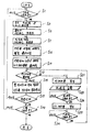
제14도는 제1도 및 제12도에 표시하는 실시예의 조작 내지 동작의 일예를 표시하는 플로우차아트 도면.FIG. 14 is a flowchart art diagram showing an example of the operation or operation of the embodiment shown in FIGS. 1 and 12. FIG.
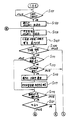
제15a도 및 제15b도는 제1도 및 제12도에서 표시하는 실시예의 조작 내지 동작의 다른 예를 표시하는 플로우차아트 도면.15A and 15B are flowchart art diagrams showing another example of the operation or operation of the embodiment shown in FIGS. 1 and 12. FIG.
* 도면의 주요부분에 대한 부호의 설명* Explanation of symbols for main parts of the drawings
10 : 자동 조립 장치 12 : 베이스 플리이포10: automatic assembly device 12: base flippo
14 : 리일 카세트 16 : 테이프 리일14: Real cassette 16: Tape real
18 : 축 20 : 테이프,18: axis 20: tape,
21 : 구멍 22 : 베이스 테이프21: hole 22: base tape
24,28 : 커버 테이프 26 : 전자 컴포우넌트24, 28: cover tape 26: electronic component
30 : 송출 유니트 32 : 송출 구멍30: dispensing unit 32: dispensing hole
34 : 절결부(인디케이터) 34a : 씨일34: notch (indicator) 34a: seal
34b : 투명부분 34c : 강자성채 필름34b:
34d : 도전 필름 36,40 : 기어34d:
38 : 복수의 핀 42 : 마찰 드럼38: plurality of pins 42: friction drum
44 : 마찰 회전판 46 : 권취 리일44: friction friction plate 46: winding rail
48,58,86.92 : 스프링 50 : 박리판48,58,86.92: Spring 50: Peeling plate
52 : 송출 레버 54 : 클릭52: delivery lever 54: click
56 : 위치 결정부재 60 : 쩔러올림핀56: positioning member 60: pull-up pin
62 : 송출대 66 : 프린트기판62: feeder 66: printed circuit board
67 : XY테이블 68,70 : 태이블67: XY table 68,70: table
72,74 : 모우터 76 : 인덱댁스 테이블72,74: motor 76: index table
78 : 진공척 80 : 가이드78: vacuum chuck 80: guide
80a : 승강편 82 : 로울러80a: getting on and off 82: roller
84 : 취부부 85 : 베어링84: mounting 85: bearing
88 : 각도 조정기 90 : 검출레버88: angle adjuster 90: detection lever
94 : 축 96 : 마이크로 스위치94: axis 96: micro switch
98a : 광전 스위치 98b1: 발광기98a: photoelectric switch 98b 1 : light emitter
98b2: 수광기 98c : 자기 검출기98b 2 :
98d : 콘텍트 100 : CPV98d: Contact 100: CPV
102 : 인터페이스 104 : 입력수단102: interface 104: input means
106 : 스타아트 스위치 108 : 스톱 스위치106: star art switch 108: stop switch
110 : 리세트 스위치 112 : RAM110: reset switch 112: RAM
114 : ROM 116 : 어드레스 카운터114: ROM 116: address counter
118 : 스텝 카운터 119 : 플러그118: step counter 119: plug
120 : 잔량 카운터 122 : 출력 인터페이스120: remaining counter 122: output interface
123 : 베이스 플레이트 구동 회로 124 : 인덱스 테이블 구동 회로123: base plate driving circuit 124: index table driving circuit
125 : 전자 밸브 128 : 각도조정기 구동회로125: solenoid valve 128: angle adjuster drive circuit
130 : 경보 장치 134 : 프로그램스텝 N0데이터130: alarm device 134: program step N0 data
136 : X축의 위치 데이터 138 : Y축의 위치데이터136: position data of the X axis 138: position data of the Y axis
140 : 각도 데이터 142 : 리일 NO데이터140: angle data 142: rail NO data
144 : 제어 명령 150,151 : 송출 갈고리144: control command 150151: feed hook
152 : 컨베이어152: Conveyor
본 발명은 테이프에 보호 유지된 전자 컴포우넌트를 한개씩 순차적으로 꺼내어 프린트기판상에 장착하도록 한 자동 조립장치에 테이프의 종단 부근에 기계 검출이 가능한 잔량인디케이터가 검출됨에 다라 경보장치의 구동으로 오퍼레이터에 테이프상의 팁형잔자 컴포우넌트의 유무를 감지하여 조립장치의 가동율을 높일 수 있도록함에 주안점이 있는 것이다.According to the present invention, an automatic assembly device which sequentially removes electronic components protected on a tape one by one and mounts them on a printed board is detected by a residual indicator capable of detecting a machine near the end of the tape. The main focus is to detect the presence of tip-type residue components on the top and to increase the operation rate of the assembly equipment.
종래의 자동조립장치의 일예로 1980년 12월 16일부로 특허된 미국 특허 제4,329,576호 및 1983년 7월 19일부로 특허된 미국 특허 제4,392,579호등에 개시되어 있었다.An example of a conventional automatic assembly apparatus is disclosed in US Patent No. 4,329,576, issued December 16, 1980, and US Patent No. 4,392,579, issued July 19, 1983.
일반적인 자동조립장치에 있어서는 전자 컴포우넌트를 테이프인 긴쪽 방향으로 대략 같은 간격으로 보호유지하고, 그 테이프에서 전자 컴포우넌트를 한개씩 순차적으로 꺼내서 프린트기판상에 조립하도록 하고 있으며, 한개의 테이프에 보호유지되어 있는 전자 컴포우넌트가 전부 꺼내지면 새로운 테이프로 교환되어 자동조립동작을 계속하도록 되어 있었다.In the general automatic assembly apparatus, the electronic components are protected and kept at approximately equal intervals in the longitudinal direction of the tape, and the electronic components are sequentially removed from the tape one by one to be assembled on the printed board. When all the electronic components were taken out, they were replaced with new tapes to continue the automatic assembly operation.
또한, 테이프의 교환을 위해서는 자동조립장치의 운전을 정지해할 필요가 있고, 상술한 바와 같이 테이프의 사전 준비를 할 수 없다는 것은 테이프를 교환하는 시간과 자동조립장치의 시간이 길어짐에 따른 가동율의 저하로 생산성이 저하되는 결점이 있었다.In addition, in order to replace the tape, it is necessary to stop the operation of the automatic assembling device. As described above, the inability to prepare the tape in advance may be related to the operation rate due to the time of changing the tape and the time of the automatic assembling device. There existed a fault that productivity fell by the fall.
본 발명은 종래의 결점을 적게하기 위하여 테이프 ·모양부재의 긴쪽 향으로 전자 컴포우넌트를 대략 같은 간격으로 보호유지하되, 그 테이프 모양부재의 긴쪽 방향의 일부에는 기계검출이 가능한 잔량인디케이터가 형성되게 하여 이 잔량인디케이터가 검출되면 제어수단은 그 검출에 응답해서 경보를 울리는 등의 소정의 처리를 실시할 수 있도록 한 것이다.The present invention is to maintain and protect the electronic components at approximately equal intervals in the longitudinal direction of the tape-shaped member in order to reduce the drawbacks of the prior art, so that a residual indicator capable of machine detection is formed in a part of the longitudinal direction of the tape-shaped member When the remaining amount indicator is detected, the control means can perform predetermined processing such as an alarm in response to the detection.
이와 같은 본 발명에 의하면 오퍼레어터는 멀지 않아 전자 부품이 없어져버릴 것임을 경보장치등에 의해서 알수 있기 때문에 새로운 전자 컴포우넌트 보호유지체를 사전에도 준비할 수가 있게되는 것이다.According to the present invention as described above, it is possible to prepare a new electronic component protection retainer in advance because the operator can know that the electronic component will be disappeared in a short distance.
따라서, 이와 같은 전자 컴포우넌트 보호유지체를 교환하기 위하여 자동조립장치를 정지하는 시간을 최소한으로 줄일 수가 있으며, 자동조립장치의 가동율을 큰폭으로 향상시킬 수가 있는 것이다.Therefore, the time required to stop the automatic assembly device in order to replace such an electronic component protection retainer can be minimized, and the operation rate of the automatic assembly device can be greatly improved.
일예로서, 한개의 전자 컴포우넌트률 프린트기판상에 장착할 경우의 예를 들어보면, 약 0 4초의 시간을 소모할 것이다.As an example, in the case of mounting on one electronic component rate printed circuit board, it will consume about 0 4 seconds.
한편, 사전 예고가 전혀 행하여지지 않은 종래의 조립장치에 있어서는 전자 컴포우넌트의 보호유지체를 새로운 것으로 교환하기 위하여 5∼10분간의 자동조립장치의 운전시간을 정지하여야만 했던 것인바, 종래의 것과 본 발명과의 교환 시간에 따른 이익은 750∼1500개가 되는 많은 전자 컴포우넌트를 조립할 수 있는 시간을 줄일 수가 있을 것이며, 전자 컴포우넌트 보호유지체의 잔량을 오퍼레이터가 사전에 알릴때, 보호유지체의 교환시간을 30초 정도로 단축시킬 수 있기 때문인 것이다.On the other hand, in the conventional assembling apparatus without any prior notice, the operation time of the automatic assembling apparatus for 5 to 10 minutes had to be stopped in order to replace the protection retainer of the electronic component with a new one. The benefit of the exchange time with the present invention can reduce the time required to assemble a large number of electronic components of 750 to 1500, and when the operator informs the remaining amount of the electronic component protection retainer in advance, This is because the exchange time of the sieve can be shortened to about 30 seconds.
이와 같은 교환시간의 단축은 테이프 리일 및 송출유니트를 한개의 리일 카세트로서 구성한 경우에 더욱 현저하게 된다.This shortening of the exchange time becomes more remarkable when the tape rail and the delivery unit are configured as one rail cassette.
본 발명의 다른 실시예에서는 잔량인디케이터를 이용해서 특성이 갖추어진 복수의 예를 들면 다이오우드나 트랜지스터등의 전자 컴포우넌트를 프린트기판에 장착할 필요가 있을 경우에 특성이 상이한 전자 컴포우넌트가 하나의 프린트기판에 조립되는 것을 확실히 방지할 수 있다.In another embodiment of the present invention, there is one electronic component having different characteristics when it is necessary to mount a plurality of electronic components, such as a diode or a transistor, on the printed circuit board having characteristics using a residual amount indicator. Can be reliably prevented from being assembled to a printed circuit board.
즉, 잔량인디케이터를 전자 컴포우넌트의 잔량이 일정 갯수로된 것을 표시할 수 있는 위치에 형성하면 되고, 하나의 프린트기판에 n개의 특성이 갖추어진 전자 컴포우넌트를 조립하는 경우에 잔량인터케이터의 검출에 대응해서 전자 컴푸우넌트의 잔량 m개와 필요한 갯수 n개와의 비교를 지작하게 된다.That is, the remaining amount indicator may be formed at a position capable of displaying a certain number of remaining amounts of the electronic component, and the remaining amount indicator is used when assembling the electronic component having n characteristics on one printed board. Corresponding to the detection of the data, a comparison between the remaining m of the electronic components and the required number n is made.
그리고 전자 컴포우넌트를 프린트기판에 조립할 때마다 잔량 m를 갱신하고 m<n가 된 시점에서 그 보호 유지체에 남은 전자 컴포우넌트를 사용하지 않도록 보호유지체를 공테이프로 보내게 되며, 따라서 특성이 다른 즉, 제조로트가 상이한 전자 컴포우넌트가 뒤섞이어져서 하나의 프린트기판에 장착되는 것을 유효하게 방지할 수 있도록 한 것으로서 이를 첨부 도면과 그 실시예에 의하여 상세히 설명하면 다음과 같다.Each time the electronic component is assembled to the printed board, the remaining amount of m is updated, and when m <n, the protective holder is sent to the blank tape so as not to use the electronic component remaining in the protective holder. The electronic components having different characteristics, that is, different manufacturing lots, can be effectively prevented from being mixed on one printed circuit board, which will be described in detail with reference to the accompanying drawings and embodiments.
제1도는 본 발명의 일실시예의 요부를 표시하는 사시도로서 이 실시에는 도선이 없는(리이드레스) 전자부품 즉, 팁형 전자 컴포우넌트를 프린트기판상에 조립하기 위한 자동조립장치이다.1 is a perspective view showing the main part of an embodiment of the present invention, which is an automatic assembly device for assembling a leadless electronic component, that is, a tip type electronic component, on a printed board.
그러나 본 발명은 도선이 있는(리이드부착) 전자 컴포우넌트를 자동적으로 프린트기판상에 장착하도록 한 장치에도 적용할 수 있다는 점을 미리 지적해 두는 바이다.However, it is pointed out in advance that the present invention can also be applied to a device in which a leaded (lead attached) electronic component is automatically mounted on a printed board.
자동조립장치(10)는 베이스플레이트(12)를 포함하고, 이 베이스플레이트(12)는 베이스플레이트 구동회로(123)(제12도)에 의해서 화살표 방향으로 이동 가능으로 지지되어 있다.The
베이스플레이트(12)위에는 복수(이 실시예에서는 5개의)리일 카세트(14-1) (14-2) (14-3) 및 (14-4)(14-5)가 서로 대체로 평행으로 재치 고정되어 있다.On the base plate 12 a plurality of (five in this embodiment) rail cassettes 14-1, 14-2, 14-3 and 14-4 and 14-5 are placed in a substantially parallel manner to each other. It is.
카세트(14-1) 내지 (14-5)의 각각에는 동일 종류 또는 상이한 종류의 팁형 전자 컴포우넌트(26)을 보호 유지한 테이프(20)가 수납되어 있다.In each of the cassettes 14-1 to 14-5, a
그리고 고정되어 형성된 소정의 취출 위치 PV에 있어서 그들 전자 컴포우넌트가 하나씩 꺼내어진다.Then, these electronic components are taken out one by one at a predetermined take-out position PV formed in a fixed manner.
베이스플레이트(12)가 화살표 방향으로 이동 가능으로 되어 있는 것은 소망하는 리일 카세트(14)를 그 고정된 취출 위치의 PV에 위치시키기 위해서이다.The
그리고 그와 같은 테이프 리일 카세트(14-1) 내지 (14-5)중에서 한개의 카세트의 선택은 각각의 프로그램스텝프마다 베이스플레이트(12)가 필요에 따라서 화살표 방향으로 이동됨으로서 달성된다.And the selection of one cassette among such tape real cassettes 14-1 to 14-5 is achieved by moving the
리일 카세트(14)는 테이프리일(16)을 포함하고, 그 테이프 리일(16)에는 축 (18)이 삽통되고, 따라서 테이프리일(16)은 각각에 설치된 축(18)에 의해서 회전자재하게 보호유지되어 있다.The
테이프리일(16)에는 전자 컴포우넌트 보호유지체 즉, 테이프(20)가 감기고 그 테이프(20)에는 복수의 팁형 전자 컴포우넌트(26)이 일정한 간격마다 보호유지되게 하였다.The
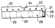
더 상세히 설명하자면 테이프(20)는 도면 제2도에 표시하는 바와 같이 팁형 전자 컴포우넌트(26)를 수납하기 위한 구멍 (21)이 형성된 베이스테이프(22)와 이 베이스테이프(22)의 두 주면에 붙여진 커버테이프(24) 및 (28)을 포함한다.More specifically, the
그리고 팁형 전자 컴포우넌트(26)은 한개씩 구멍(21)안에 봉입한다.And the tip type
이와 같은 테이프(20)은 테이프리일(16)으로부터 인출되어 송출유니트(30)으로 이동되게 된다.Such a
그리고 테이프(20)에는 도면 제3도에 표시하는 바와 같이 이 테이프(20)을 일정한 피치로 테이프 리일 (16)으로부터 인출하기 위한 송출구멍 (32)를 형성한다.In the
또한, 테이프(20)의 종단부근의 측단에는 도면 제3도에서 표시하는 바와 같이 절결부(34)가 형성된다.In addition, a
이 절결부(34)는 잔량인디케이터로서 가능하고 그 위치로부터 뒤에는 팁형 전자 컴포우넌트(26)가 아주 조금 밖에 남아 있지 않음을 표시한다.This
이와 같은 잔량인디케이터인 절결부(34)의 검출에 관해서는 뒤에 도면 제6도 및 제7도를 참조하여 설명하기로 하되, 먼저 도면 제4도를 참조하여 리일카세트(14)의 구성에 대하여 좀더 상세히 설명하기로 한다.The detection of the
리일 카세트(14) 내에는 앞에서 설명한 바와 같이 테이프 리일(16)과 송출유니트(30)이 연결판(도시하지 않음)에 의해서 일체적으로 연결되어 수납한다.In the
송출유니트(30)은 테이프 송출구멍(32)와 (제3도)에 계합하는 복수의 핀(38)을 가지는 기어(36)를 포함 한다.The
따라서, 기어 (36)이 회동되는 것에 의하여 테이프(20)을 화살표 B방향으로 인출할 수 있다.Therefore, the
이 기어 (36)에 맞물리도록 기어 (40)을 설치하여 마찰드럼(42)에 고정설치하였으며, 마찰드럼(42)의 주측면에는 커버테이프 권취리일(46)에 고착된 마찰회전판(44)의 둘레 가장자리를 스프링(48)에 의하여 압정되게 하고 커버테이프 권취리일(46)은 취출위치 PV의 앞에 설치된 커버테이프 박리판(50)에 의해서 박리된 커버테이프(28)을 귄취하도록 하였다.The
송출 유니트(30)에는 기어(36)을 일정한 피치마다 회동시키기 위한 송출레버(52)를 설치하며, 이 송출레버(52)에는 기어(36)의 톱니에 계합하는 클릭(54)를 고정 설치하였으며. 송출레버 (52)를 화살표 C방향으로 눌러주므로서 클릭(54)의 작용에 의해서 기어(36)의 화살표 D방향으로 회동되고, 핀(38)에 의해서 테이프(20)이 화살표 B방향으로 일정한 피치마다 송출되도록한 것이며, 기어 (36)의 아랫쪽에는 스프링(58)의 탄발력을 이용해서 기어(36)의 위치를 고정하기 위한 결정부재(56)을 설치하였다.The
취출 위치 PV에는 인덱스테이블(76)(제1도)에 의하여 2점 쇄선으로 표시하는 바와 같이 진공척(78)이 끌어오도록 한것이며, 이 진공척(78)에 관해서는 뒤에 상세히 설명하기로 한다.The
취출 위치 PV에는 진공척(78)의 하강동작에 대응하여 테이프(20)의 이면으로부터 팁형 전자 컴포우넌트를 찔러 올리는 찔러올림핀(60)을 설치하였다.The ejection position PV was provided with the sticking
이와 같은 구성의 테이프 리일카세트(14)에서 테이프 리일(16)으로부터 일출된 테이프(20)는 그 송출구멍(32)(제3도)가 기어(36)의 핀(38)에 계합하고 있기 때문에 (52)가 화살표 C방향으로 압하되면 기어(36)이 화살표 D방향으로 회동함으로서 일피치분만 송출됨과 동시에 기어 (40) 특, 마찰드럼 (42)가 화살표 E방향으로 회전하게 되며, 따라서, 마찰드럼 (42)에 압접되 있는 마찰회전판(44) 즉, 커버테이프 귄취리일(46)이 화살표 F방향으로 회전한다.In the
따라서, 커버테이프 박리판(50)에 의해서 박리된 커버테이프(28)이 권취리일 (46)에 권취되는 것이며, 그리고 팁형 전자 컴포우넌트(26)은 찔러올림핀(60)에 의해서 찔러올려지면서 진공척(78)에 의해서 빨아 올려지고 테이프(20)에서 꺼내어지게 된다.Therefore, the
이와같이 테이프 리일(16)과 송출유니트(30)을 일체적으로 하나의 카세트에 수납하도록 하면 테이프의 교환 작업을 대단히 간단히 실시할 수 있다.In this way, if the
또한, 송출레버(52)는 통상의 자동조립동작에 있어서는 뒤에 설명하는 인덱스테이블(76)(제1도)의 회전에 상응해서 화살표 C방향으로 눌러 내려지는 것이다.In addition, in the normal automatic assembly operation, the
따라서, 이 실시예에서는 리일 카세트(14)안에는 테이프(20)을 인출하고 혹은 송출하기 위한 구동원은 없으며, 테이프(20)은 인덱스테이블(76)이 회전 구동축에 취부된 캠으로 구동되는 레버에 의해서 일정 피치마다 인출된다.Therefore, in this embodiment, there is no driving source for pulling out or feeding out the
그러나, 예를들면 기어(36)을 인덱스테이블(76)으로부터의 구동력에 의하는 것이 아니고, 예를들면 펄스 모우터등의 독자의 구동원으로 구동이 가능하도록 만들어도 좋다.However, for example, the
다시 제1도로 돌아와서 베이스플레이트(12)의 이동 방향A와 평행으로 뻗어서 송출대(62)는 프린트기판(66)을 이동시키는 송출 갈고리(150) 및(151)을 화살표 G방향으로 이동시킨다.Returning to the first road again, it extends in parallel with the movement direction A of the
즉, 컨베이어(152)로 송달된 프린트기판(66)은 송출갈고리(151)에 눌러서 XY테이블(67)위로 반입되고 또한, XY테이블 위에 있는 프린트기판(66)은 송출 갈고리(150)에 의해 눌려서 거기서부터 반출된다.That is, the printed
그 후에, 송출대대(62)는 Q방향으로 회전하고 송출 갈고리(150) 및 (151)를 들어을리고 화살표 G방향과 반대방향으로 원래의 위치까지 돌아간다.Thereafter, the
이 송출대(62) 즉, 프린트기판(66)의 반송은 전자밸브 구동회로(125)에 의하여 구동되는 에에실린더(도시 하지 않음)에 의해서 달성된다.The conveyance of this delivery table 62, that is, the printed
XY테이블(67)은 두개의 테이블(68) 및 (70)을 포함하고 아랫쪽의 테이블 (68)이 모우터(72)에 의하여 보올나사(도시하지 않음)를 개재하여 X축 방향, 즉 화살표 G방향으로 변위된다.The XY table 67 includes two tables 68 and 70, and the lower table 68 is driven by the
그리고 이 테이블(68)위에서 테이블(70)이 모우터(74)에 의하여 보올나사(도시하지 않음)을 개재하여 Y축 방향으로 변위될 수 있다.On the table 68, the table 70 can be displaced in the Y-axis direction by a
따라서, 두개의 모우터(72) 및 (74)를 구동해서 XY테이블(67)을 움직이므로서 프린트기판(66)을 XY평면의 소정위치로 위치 결정할 수 있다.Therefore, by driving the two
베이스플레이트(12)와 XY테이불(67)과의 사이의 윗쪽에는 인텍스테이블(76)이 설치되고, 이 인덱스테이블(76)에 관련해서 복수의 (이 실시 예에서는 네개의) 진공척(78)이 설치된다.An index table 76 is provided above the
이 인덱스테이블(76)은 테이블 구동회로(124)(제12도)에 의해서 화살표 H방향으로 회전구동된다.The index table 76 is rotated in the direction of arrow H by the table driving circuit 124 (Fig. 12).
즉, 테이블 구동회로(124)는 도시안하지만 감속기 부착 모우터틀 포함하고, 인덱스테이블(76)은 이 모우터의 출력축의 일회전마다 90°(360/진공척(78)의 수(4))씩 회전된다.That is, the
그리고 인덱스테이블(76)이 화살표 H방향으로 회전되는 점에 상응하여 각 진공척(78)이 전자 컴포우넌트의 취출위치 PV로부터 각도 조정기(88)로, 그리고 거기서부터 기판(66)의 윗쪽으로 간헐적으로 순서대로 위치 결정이 된다.Corresponding to the point that the index table 76 is rotated in the direction of the arrow H, each
그 때문에 송출레버(52)(제4도)는 인덱스태이블(76)의 1/4회전마다 한번 화살표 방향으로 눌려 내려지게 된다.Therefore, the feeding lever 52 (FIG. 4) is pushed down in the direction of the arrow once every 1/4 turn of the index table 76. As shown in FIG.
그 때문에 인덱스테이블(76)의 1/4회마다 팁형 전자 컴포우넌트가 취출 위치 PV로 가져오게 된다.For this reason, the tip type electronic component is brought to the extraction position PV every quarter of the index table 76.
또한, 진공척(78)은 인텍스테이블 구동축에 의하여 구동되는 기계식 밸브(도시지 않음)에 의해서 그 부압이 제어된다.In addition, the negative pressure of the
즉, 기계식 밸브(도시하지 않음)가 필요한 타이밍으로 ON이 되면, 그것에 의하여 진공척(78)에 적당한 부압원이 접속되고, 진공척(78)에 보호유지된 팁형 전자 컴포우넌트를 흡인하기 위한 흡인력이 생긴다.That is, when a mechanical valve (not shown) is turned ON at a necessary timing, a suitable negative pressure source is connected to the
각도 조정기(88)은 진공척(78)에 보호유지된 팁형 전자 컴포우넌트의 전술한 X-Y축(제1도)에 대한 각도를 조정하기 위한 것이고, 각도 조정기 구동회로(128) (제12도)에 의해서 회전된다.The
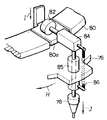
여기서, 제5도를 참조해서 진공척 (78)의 동작에 관하여 설명한다.Here, the operation of the
제5도에 표시하는 바와 같이 인텍스 테이블(76)의 위쪽에 그 외주를 연하여 가이드(80)이 고정 설치되었으며. 그 가이드(80)는 진공척(78)이 하강할 필요가 있는 위치 즉, 제1도에 있어서의 취출위치 PV, 각도 조정기(88)의 위치 및 XY테이블(67)의 위치에서 다른 부분하고는 잘라버려진 승강편(80a)으로서 형성된다.As shown in FIG. 5, the
이 승강편(80a)는 캠(도시하지 않음)에 의하여 화살표 I방향으로 하강기능으로 되어 있다.This elevating
가이드(80)의 윗표면을 진동 가능한 로울러(82)가 취부부(84)에 연결되고, 이 취부부(84)에는 인덱스테이블(76)이 고착된 베어링(85)를 삽통한 진공척(78)의 일단이 취부된다.The
그리고 취부부(84)는 그 일단이 인덱스테이블(6)에 고착된 스프링(86)에 의하여 정상적으로는 아랫쪽에 늘어져 있다.And the mounting
상술한 바와 같은 구성에 있어서 인텍스 테이블(76)의 회전에 상응해서 진공척 (78)이 화살표 H방향으로 회전된다.In the above-described configuration, the
또, 인덱스테이블(76)의 회전에 상응해서 가이드(80)위를 로울러(82)가 구동한다.In addition, the
그리고 진공척(78)을 하강시킬 필요가 있는 위치에서 승강편(80a)가 캠(도시하지 않음)에 의하여 하강된다.The
따라서, 로울러(82)가 그 하강된 승강편(80a)에 의하여 하강되고 추부부(84)가 스프링 (86)에 의하여 하강되고, 그것에 상응하여 베어링(85)에 삽통된 진공척 (78)이 하강된다.Thus, the
그리고 캠(도시하지 않음)이 승강기(80a)를 상승시키면 로울러(82)는 고정된 위치에 있는 가이드(80)위에 있는 경우와 마찬가지 수준으로 되고 진공척(78)은 다시금 그 호음포지션으로 돌려 보내진다.Then, when the cam (not shown) raises the
이와 같이하여 진공척(78)의 승강동작이 실시된다.In this way, the lifting operation of the
이와 같은 진공척 (78)의 승강동작은 본 발명에 있어서 그다지 중료하지 않기 때문에 여기서는 그 이상의 상세한 설명은 생략하기로 한다.Since the lifting operation of the
또한, 이 실시예에서는 인덱스 테이블에 의하여 팁형 전자 컴포우넌트를 꺼내서 기판상에 장착하도록 하였다.In this embodiment, the tip type electronic component was taken out by the index table and mounted on the substrate.
그러나 이와 같은 인덱스테이블을 사용하는것 이외에, 예를들면 앞서 인용한 미국 특허 제4,239,576호 및 제4, 393,579호 등에 개시된 구성으로 팁형 전자 컴포우넌트를 꺼내고 또한, 프린트기판에 장착하도록 해도 무방하다.However, in addition to using such an index table, for example, the tip type electronic components may be taken out and mounted on a printed circuit board using the configurations disclosed in, for example, US Patent Nos. 4,239,576 and 4,393,579.
다음에는 제6도 및 제7도를 참조하여 이 실시예의 한가지 특징인 잔량인디케이터를 검출하기위한 기구에 관하여 설명하기로 한다.Next, with reference to Figs. 6 and 7, a mechanism for detecting the remaining indicator, which is one feature of this embodiment, will be described.
제6도 및 제7도에서는 잔량인디케이터로서 제3도에 표시하는 바와 같은 절결부 (34)를 형성한 예가 표시 되어있다.6 and 7 show an example in which the
그리고 리일 카세트(14-1) 내지 (14-5) (제1도)의 외부이면서 테이프(20)의 송출 경로상에 검출 레버(90)이 설치되었으며, 더 상세히 설명하자면 자동조립장치 (10)(제1도)의 소정 위치에서 검출레버(90) 축(94)에 의하여 화살표 K방향으로 회동 가능으로 지지되고 그 검출레버(90)의 선단은 스프링(92)에 의하여 테이프(20)의 측단에 당접되어 있다.And a
한편, 검출레버(90)의 타단의 근방에 그 애크류에이터가 위치하도록 마이크로수위치(96)이 취부되어 있다.On the other hand, the micro
또한, 검출기로서의 레버(90) 및 마이크로 스위치(96)은 리일 카세트(14-1) 내지(14-5)(제1도)의 내부에 설치해도 좋다.In addition, the
그리고 테이프(20)의 테이프 리일(16)으로부터의 인출에 상응하여 검출레버 (90)의 일단 이 잔량인디케이터 즉, 절결부(34)에 감입하면 이 검출레버(90)은 스프링 (92)의 탄발력에 의하여 축(94)를 중심으로 하여 화살표 K방향으로 회동된다.In response to the withdrawal from the
따라서,이 검출레버(90)의 다른쪽 끝이 마이크로 스위치(96)의 애크류에이터에 접속하고 이 마이크로 스위치(96)이 ON 또는 OFF된다.Therefore, the other end of this
이와 같이하여 이 마이크로 스위치(96)으로부터는 절결 즉, 잔량인디케이터 절결부(34)를 검출한 것을 표시하는 신호가 출력될 수 있다.In this way, a signal indicating that the cutoff, that is, the
잔량인디케이터와 그 검출 기구는 그밖에 제8a도 및 제8b도 내지 제11도에 표시하는것과 같은 것을 사용해도좋다. 제8a도는 잔량인디케이터의 다른 예를 표시하는 개략평면도이고, 제8b도는 그 측면도로서, 테이프(20)의 커버테이프(28)의 소정의 위치에서. 예를들면 광흡수성의 혹은 빛의 난반사를 발생시키는 재질의 씨일(34a)가 붙여진다.The remaining amount indicator and its detection mechanism may be used in addition to those shown in FIGS. 8A and 8B to 11. FIG. 8A is a schematic plan view showing another example of the remaining amount indicator, and FIG. 8B is a side view thereof at a predetermined position of the
그리고 테이프(20)의 송출경로의 윗쪽에 반사형의 광전스취치(98a)를 취부한다.Then, a reflective
통상 상태에서는 그 광전스위치 (98a)로부터의 빛은 커버테이프(28)에 의해서 반사되어 그 광전 스위치(98a)에다시 돌아온다. 그런데, 씨일(34a)의 위치에서는 빛은 흡수되며 혹은 난반사되고 광전 스위치(98a)에는 되돌아오지 않는다.In a normal state, light from the
따라서, 이광전 스위치(98a)에 의해서 잔량인디케이터로서의 씨일(34a)을 검출할 수 있는 것이다.Therefore, the
또한 이 씨일(34a)를 붙이는 위치는 테이프(20)의 축단이라도 무방하다.The
제9도는 잔량인디케이터의 다른 예를 표시하는 계략측면도로서, 테이프(20)의 긴쪽 방향의 일부에 송출 구멍(32)(제3도)하고는 구별할수 있는 투명부분 또는 통공 (34b)를 형성한다.FIG. 9 is a schematic side view showing another example of the remaining amount indicator, and forms a transparent portion or through
그리고 테이프(20)을 사이에 두고 발광기(98b1) 및 수광기 (98b2)를 대향적으로 배치한다.The light emitter 98b 1 and the light receiver 98b 2 are disposed to face each other with the
통상 상태에서는 발광기(98b1)로부터의 빛은 테이프(20)에 의해서 차단되어서 수광기(98b2)에 까지는 도달하지 않는다.In the normal state, light from the light emitter 98b 1 is blocked by the
그리고 테이프의 종단부에서 투명부분(34b)가 발광기 (98b1)과 수광기 (98b2)와의 사이에 위치했을때에 수광기 (98b2)는 발광기 (98b1)로부터의 빛을 받는다.And when the transparent portion (34b) from the tape end portion have been positioned between the light emitter (98b 1) and a light receiver (98b 2) a light receiver (98b 2) is subjected to light from a light emitter (98b 1).
따라서 수광기(98b2)에 의하여 투명부분(34B) 즉 잔량인디케이터를 검출할 수가 있다.Therefore, the transparent part 34B, that is, the residual amount indicator, can be detected by the light receiver 98b 2 .
제10도는 잔량인디케이터의 또다른 예를 표시하는 개략 측면도로서 잔량인디케이터로서 테이프(20)의 긴 쪽 방향의 일부에 자성재료, 에를들면 강자성체의 필름 (34c)를 붙인다.FIG. 10 is a schematic side view showing another example of the remaining amount indicator, in which a magnetic material, for example a
그리고 테이프(20)의 송출경로의 원쪽에 예를들면 호울소자를 포함하는 자기검출기(98c)를 취부한다.Then, a
강자성체필름(34c)를 검출하면 그 자기검출기(98c)에서 검출신호를 얻을 수 있다.When the
또한 강자성체필름(34c)를 훼라이트와 같은 자석제료로 형성하면 자기검출기 (98c)는 그것에 감응하는 리이드 스위치와 같은 것이라도 좋다.If the
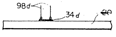
제11도는 잔량인디케이터의 다른예를 표시하는 계략측면도로서, 이 예에서는 테이프(20)위에 도전필름(34d)를 잔량인디케이터로서 붙인다.11 is a schematic side view showing another example of the remaining amount indicator. In this example, the conductive film 34d is pasted on the
그리고 테이프(20)의 윗표면에 접촉하고 또한 상호 간격을 둔 두개의 콘텍트 (98d)를 취부한다.Then, two
그리고 이 콘텍트(98d)사이에는 적당한 진압원이 접속되어 있다.An appropriate suppression source is connected between the
통상 상태에서는 콘텍트(98d)는 테이프(20)의 표면에 절연재료이기 때문에 열려있는 데로이다.In the normal state, the
그런데 도전필름(34d)이 그 위치에 오면 이 필름(34d)에 의하여 두개의 콘텍트 (98d)는 도통상태가 되고 따라서 이 콘텍트(98d)에서 검출신호를 얻을 수 있다.By the way, when the conductive film 34d comes to the position, the two
또한 잔량인디케이터와 그 검출기구에 관해서는 그 밖에 정전용량의 변화를 검출하도록 한 방법 등 임의의 구성이 이용될 수 있는 것이 해당업자 들에게는 쉽게 이해가 될 것이다.In addition, it will be readily understood by those skilled in the art that any remaining amount indicator and its detector mechanism can be used in any configuration such as a method for detecting a change in capacitance.
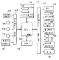
제12도는 제1도 실시예의 전기회로를 표시하는 블록도로서 이 실시예에서는 CPU(100)으로서 예를들면 인텔(Intel)의 8080이 사용된다.FIG. 12 is a block diagram showing the electric circuit of the first embodiment. In this embodiment, for example,
이 CPU(100)에는 입력 인터페이스(102)를 통해서 키이보오드, 테이프리이더 혹은 플록피디스크드 라이브 유니크 등의 프로그램과 기타의 데이터 등을 입력하기 위한 입력수단(104)가 연결된다.The
입력 인터페이스(102)에는 더욱 스타아트스위치(106), 스튜스위치(108) 및 리세프스위치(110)이 접속되는 동시에 전술한 잔량인디케이터 검출수단, 예를들면 마이크로스위치(96)이 접속된다.The star interface switch 106, the stew switch 108, and the
스타아트스위치(106)은 자동조립동작을 개시시키기 위한 지령스위치이며, 스톱스위치(108)은 그 자동조립 동작을 정지시키기 위한 스위치이고, 리세트스위치 (110)은 뒤에 설명하는 경보장치 (113)을 리세트시키기 위한 스위치이다.The star art switch 106 is a command switch for starting the automatic assembly operation, the stop switch 108 is a switch for stopping the automatic assembly operation, and the
CPU(100)에는 .RAM(112) 및 ROM(114)가 연결되고 RAM에는 입력수단 (104)에서 입력된 프로그램이 로우드되는 어드레스 카운터(116)이 형성되는 동시에 이 RAM(112)에 일부분이 스텝카운터(118)과 잔량카운터(120) 및 검출플랙(119)으로 사용된다.The
ROM(114)에는 시스템 프로그램을 저장해두거나 혹은 유우저 프로그램을 저장해 두기 위한 것이다.The
CPU(100)은 출력 인터페이스(122)를 중개하여 베이스플레이트 구동회로 (123) 등에 제어신호를 부여한다.The
즉, 베이스플레이트 구동회로(123), 인덱스테이블 구동회로(124) 송출대(62) (제1도)를 제어하는 전자밸브 구동회로(125), XY테이블(67)(제1도)를 제어하는 보올나사 구동회로(126) 모우터(72) 및 (74), 각도 조정기 구동회로(128) 및 경보장치 (130)이 출력 인터페이스(122)를 통하여 CPU(100)으로 연결된다.That is, the solenoid
경보장치(130)에는 버저(buzzer)와 같은 가청적인 경보를 내는 것 흑은 플렛쉬라이드와 같은 가시적인 경보를 내는 것 등이 단독으로 혹은 조합되어 사용되고 있다.The
다음에는 제13도를 참조하며 프로그램포옴패트의 일예를 설명하기로 한다.Next, an example of a program form pad will be described with reference to FIG. 13.
이 실시예에서는 프로그램은 ASCⅡ(아스키)코우드로 제작된다. 이 프로그램은 찬공 테이프, 자기디스크, 자기드럼 혹은 다른 기억수단으로부터 입력수단(104)(제12도)을 통하여 CPU(100) 즉 RAM(112)로 입력될 수 있다.In this embodiment, the program is made of ASCII code. This program can be input from the blank tape, the magnetic disk, the magnetic drum or other storage means to the
더우기 프로그램은 영숫자 입럭 가능한 키이보오드와 같은 입력수단으로부터 입력되어도 좋다.Furthermore, the program may be input from an input means such as an alphanumeric key board.
이 제13도에서는 한 개의 프로그램스텝이 표시되어 있다.In FIG. 13, one program step is displayed.
즉 이 실시예에서는 프로그랩 스텝 NO 데이터(134)와 칩형 전자컴포우넌트 (26)의 프린트기판(66)에게의 장착위치의 X방향(제1도)에 관한 위치데이터(136)과 동일하게 Y방향(제1도)의 위치데이터(138), 각도데이터(140), 리일 NO 데이터 (142) 및 제어코맨드(144)를 포함한다.In other words, in this embodiment, the program step NO
각도 데이터(140)는 각도조정기(88)에 의하여 조정해야 할 각도의 데이터이고, 리일 NO 데이터는 리일 카세트(14-1) 내지 (14-5)(제1도)의 어느 것인가를 표시하는 데이터이다.The
프로그램스텝 NO, 데이터(134)는 전기의 전자 컴포우넌트(26)을 프린트기판 (66) 위에 장착하여야 할 순서를 표시하며, 스텝 NO가 예로 「001」이면 첫번째에 장착하는 것을 의미하고, 이하 차례로 「OO2」이면 두 번째에 장착하는 것을 의미하고, 그 스텝 NO에 대응하는 각 데이터(136)(138)(140)(142) 내용에 따라 장착되는 것이다.The program step NO and
그리고 제어코맨드(144)에 ASCll(아스키)로우드의 ″E″가 있으면 그 프로그램 스텝이 엔드스텝임을 표시한다.If the
또한 만약에 이 제어코맨드(144)로서 ″1″이 있으면 그 스텝에서는 특성이 유사한 복수의 다이오우드 등의 전자 컴포우넌트(이하 ″짜맞춤의 전자컴포우넌트″라고 칭함)을 한 개의 프린트기판(66)(제1도)에 조립해야 함을 표시한다.If ″ 1 ″ is present as the
다음은 제14도를 참조하여 실시예의 조작 내지 동작에 관하여 설명하기로 한다.Next, operation and operation of the embodiment will be described with reference to FIG.
전원스위치(도시하지 않음)를 투입하고 스타아트스위치(106)를 ON해 줌으로서 자동조립동작이 시작된다.The automatic assembly operation is started by turning on the power switch (not shown) and turning on the star art switch 106.
이 시작에 앞서서 자동조립장치에는 필요한 리일카세트가 취부되고 또한 필요한 프린트기판이 반송용의 프레임에 취부되어 있는 것은 물론이다.Prior to this start, it is obvious that the necessary rear cassette is attached to the automatic assembling device, and the necessary printed board is attached to the transport frame.
또한 예를들면 전기의 입력수단(104)의 일부인 테이프리이터로부터 프로그램테이프가 읽어지고, CPU(100)에 관련하는 RAM(112)의 어드레스카운터(116)측의 각 프로그램마다에 일보 진행하면서 그 어드레스 카운터 (116)에 지정된 RAM(112)의 소정에 리어에 프로그램 코오드(제13도)가 차례로 로우드 되게 된다.Further, for example, a program tape is read from a tape writer which is a part of the electric input means 104, and the program tape is read for each program on the
이와같이 로우드된 상태로 이하 전자컴포우넌트(26)의 프린트기판(66)에서의 장착동작에 대하여 이하 제14도와 제15a도 및 제15b도에 의하여 설명한다.The mounting operation of the
스텝 S1에서 CPU(100)는 스타아트스위치(106)가 ON이 된것을 검지하면 CPU(100)은 이어서 스텝 S3에서 제1도에 표시하는 것처럼 프린트기판(66)을 XY레이블(67)위에 토우딩한다. 즉, 이 스텝 S3에서 CPU(100)은 출력 인터페이스(122)를 중개하여 전자밸브 구동회로(125)에 신호를 주고 실린더(도시하지 않음)를 구동시키고 프린트기판(66)을 XY테이블(67)위로 반입한다.When the
이어지는 스텝 S5에 있어서 CPU(100)은 RAM(112)안의 어드레스카운터 (116)을 클리어시킨다.In the following step S5, the
즉 이 스텝 S5에선 스텝카운터(118)이 초기화된다.That is, in step S5, the step counter 118 is initialized.
스텝 S7에서 CPU(100)는 앞서의 스텝 S5에 있어서 클리어한 스텝카운터 (118)을 증대하고, 그에 의해서 프로그램으리 최초의 스텝이 지정된다.In step S7, the
그리고 어드레스카운터(116)에서 지정된 어드레스카운터(116)내의 프로그램 스텝의 데이터가 CPU(100)내부의 적당한 레지스터(도시하지 않음)에서 읽어져서 로우드된다.The data of the program step in the
다음의 스텝 S9에서 CPU(100)은 그 레지스터에서 읽어진 그 프로그램 스텝의 내용 즉 리일 NO 테이타(142)(제13도)에 상응하여 베이스플레이트 구동회로(123)에 대하여 출력 인터페이스(122)를 중개하여 제어신호를 보내고 꺼내서 위치 PU(제1도)에 그 번호의 테이프 리일카세트를 위치결정한다.In the next step S9, the
이어서 스텝 S11에 있어서 CPU(100)은 그 프로그램 스텝의 내용 즉 X방향의 위치데이터(136) 및 Y방향의 위치데이터(138)에 따라서 XY테이블(67)을 위치결정한다.In step S11, the
스텝 S13에서 CPU(100)은 마이크로스위치(96), 즉 잔량인디케이터 점출수단으로부터의 잔량인디케이터의 검출신호가 있는지 없는지 즉 그 리일카세트안에 충분한 양의 팁형전자 컴포우넌트가 아직도 있는가 없는가를 판단한다.In step S13, the
그리고 이 스텝 S13에서 ″NO″이면 CPU(100)은 이어지는 스텝 S15로 이동하고, 만약에 스텝 S13에서 ″YES″로 판단했을 경우에 스텝 S21로 진입한다.If it is "NO" in step S13, the
스텝 S1S에서는 팁형전자 컴포우넌트를 진공척(78)에 의해서 흡착하고 XY테이블(67)위의 프린트기판 (66)에 장착한다.In step S1S, the tip type electronic component is sucked by the
즉, CPU(100)은 인텍스테이블 구동회로(124)에 제어신호를 인가하여 인덱스테이블(76)(제1도)을 1/4회전시키고, 진공척(78)에 의해서 취출위치 PU로 가져온 팁형전자 컴포우넌트를 꺼낸다 계속해서 그 팁형 전자컴포우넌트를 보호유지한 진공척 (78)이 인덱스테이블(76)의 회전에 상응하여 각도조정기(88)로 가져오게 된다.That is, the
그리고 CPU(100)에서는 앞서 레지스터에 로우드한 그 프로그램스텝의 내용, 극 각도데이타(140)(제13)도에 상응해서 출력 인터폐이스(122)를 통하여 각도조정기 구동회로(128)에 제어신호를 부여한다. 따라서 진공척(78)에 흡착되어 있는 팁형전자컴포우넌트가 소망의 각도에서 출현된다.The
이어서 CPU(100)이 XY테이볼(67), 즉 프린트기판(66)을 위치결정한다The
다음의 스텝 S17에서 CPU(100)은 그 프로그램스텝의 제어코맨드에 ″E″가 있는가 없는가를 보고 최종 프로그램스텝인가 아닌가를 판단한다.In the next step S17, the
만약에 최종 프로그램스텝이 아니라면 앞서의 스텝 S7로 돌아오고, 또는 최종 프로그램스텝이라면 CPU(100)은 이어지는 스텝 S19에서 RAM(112)만의 소정의 플랙(도시하지 않음)을 보고, 스톱스위치(108)(제12도)이 ON이 되어 있는지 없는지를 판단한다. 만약 이 스텝 S19에 있어서 ″ON″이면 앞서의 스텝 S3으로 돌아가고, 만약에 ″YES″이면 자동조립모우드의 동작이 끝난다.If it is not the last program step, the process returns to the previous step S7, or if it is the last program step, the
앞서의 스텝 S13에서 잔량인지케이터인 절개부(34)의 검출신호가 있을 경우에는 스텝 S21에서 CPU(100)은 출력 인터페이스(122)를 중개하여 경보장치(130)에 대하여 신호를 부여한다.If there is a detection signal of the
따라서 스텝 S21에서 경보장치(130)이 작동하고 가청적 경보 및 혹은 가시적 경보가 실시된다.Therefore, in step S21, the
오퍼레이터는 그 경보장치(130)에 의한 경보를 알아서 팁형전자 컴포우넌트의 잔량이 적어진 리일카세트를 새것과 교환한다(스텝 S23), 경보장치(130)은 다음의 스텝 S25에서 리세트스위치(110)(제12도)가 ″ON″이 될때까지 경보를 속행하고, 리세트스위치(110)가 ″ON″이 되는 스텝 S27에서 CPU(100)은 경보장치(130)에 대한 신호를 정지한다.The operator recognizes the alarm by the
그리고 스텝 S29에서 스타아트스위치(106)가 다시 ″ON″이 되면 앞서의 스텝 S13으로 돌아간다.When the star art switch 106 becomes " ON " again in step S29, the process returns to the previous step S13.
따라서 스텝 S13에서 잔량이 적어진것이 검출됐는데도 불구하고 새로운 카세트와 교환되지 않으면 카세트가 교환될때까지 자동조립장치는 자동조립모우드의 운전을 중단하게 된다.Therefore, even if it is detected in step S13 that the remaining amount is small, if it is not replaced with a new cassette, the automatic assembling device stops the operation of the automatic assembly mode until the cassette is replaced.
다음은 제15도를 참조하여 자동조립 모우드에서의 별도의 조작 내지 동작에 관하여 설명하고저 한다.Next, with reference to Figure 15 will be described a separate operation or operation in the automatic assembly mode.
이 제15도에 표시하는 플로우차아트 도면은 ″짜맞춤의 전자컴포우넌트″를 프린트기판 위에 조립하는 경우에 유리하게 적용된다.The flowchart art drawing shown in FIG. 15 is advantageously applied when assembling " matching electronic components " on a printed board.
제15도에 표시하는 최초의 스텝 S101에서 CPU(100)은 스타아트스위치 (106)가 눌려져 있는지의 여부를 판단하고 스타아트스위치(106)이 눌러졌으면 CPU (100)은 다음의 스텝 S103에서 어드레스카운터(116)(제12도)를 클리어시키고, 다음의 스텝 S105에서 그 스텝카운터(118)을 인크리멘트(increment)한다.In the first step S101 shown in FIG. 15, the
따라서 이 스텝 S105에서 프로그램스텝이 지정되고 다음의 스텝 S107에서는 프로그램스텝의 프로그램코우드(제13도)의 내용, 즉 리일 NO 데이타(142)에 상응하여 베이스플레이드 구동회로(123)을 제어하여 그프로그램스텝에 필요한 번호의 리얼이 취출위치 PU(제1도)로 오도록 위치를 결정한다.Therefore, in step S105, the program step is specified, and in the next step S107, the base
다음의 스텝 S109에서 CPU(100)은 적당한 레지스터로 읽어 내어진 그 프로그램스텝의 내용, 즉 제어명령(144)에서 ″1″이 있는가 없는가, 즉 그 프로그램스텝에서 조립해야 할 전자컴포우넌트가 ″짜맞춤의 전자 컴포우넌트″인가 아닌가를 판단한다. 만약 ″짜맞춤의 전자컴포우넌트″이면 스텝 S125에서 앞서의 제14도에서 표시하는 플로우차아트 도면의 스텝 S15로 표시한 동작과 동일한 동작이 실시되는 것이다.In the next step S109, the
만약에 제어코명령(144)가 ″1″이면 CPU(100)은 이어지는 스텝 S111에서 검출플러그(119)를 보고 그 플러그(119)가 세트되어 있는지 어떤지를 판단한다.If the
이어지는 스텝 S113에서 CPU(100)은 잔량인지케이터인 절개부(34)를 검출수단, 예를들면 마이크로스위치(96)이 검출했는지의 여부를 판단한다.In the following step S113, the
이 스텝 S113에 있어서 ″YES″이면 다음의 스텝 S115에 있어서 CPU(100)은 RAM(112)안의 검출플러그(119)을 클리어시킨다.If YES in this step S113, the
그 검출플러그(119)가 클리어되면 그 시점에서 팁형 전자컴포우넌트의 나머지 갯수를 예를들면 40개로서 명확히 파악할 수 있다. 왜냐하면, 잔량인디케이터인 절개부 (34)(제3도)가 잔량40개의 위치로 형성되어 있기 때문이다.When the
따라서 CPU(100)은 다음의 스텝 S117에서 RAM(112)안의 잔량카운터 (120)에 대하여 그 잔량 예를들면 40개를 세트한다.Therefore, the
그에 의하여 ″짜맞춤의 전자컴포우넌트″에 대한 특별한 제어가 개시된다.This initiates special control over the ″ matching electronic component ″.
스텝 S119에서 CPU(100)은 그 프로그램스텝이 잔량카운터(120)를 세트해서 뒤의 최초의 ″짜맞춤″인지 아닌지를 판단한다.In step S119, the
만약에 최초의 ″짜맞춤″이라면 다음의 스탭 S121에서 CPU(100)은 나머지 갯수 m이 ″짜맞춤의 전자컴포우넌트″의 수 n보다 많은지 어떤지틀 판단한다.If it is the first " framework ", then in the next step S121, the
이것은 미리 프로그램로 짜여져 있는 개수 n와 잔량카운터(120)내의 수치를 CPU(100)에 의하여 비교함으로서 판단할수 있다. 스텝 S119의 판단에서 ″NO″일때 및 스텝 S121에서 ″YES″일때에는 다 같이 스텝 S123으로 이행한다.This can be judged by comparing, by the
CPU(100)은 그 스텝 S123에서 잔량카운터(120)을 감소 내지는 갱신해서 다음의 스텝 S125에서 앞서의 제14도의 스텝 S15와 마찬가지로 팁형 전자컴포우넌트틀 진공척(78)(제1도)에 의해서 흡착하고 XY테이블(67)위에 있는 프린트기판(66)에 그 팁형 전자컴포우넌트를 장착한다.In step S123, the
만약에 m<n이면, 즉 그 리일카세트에 남아 있는 팁형 전자컴포우넌트의 갯수 m이 1조에 필요한 갯수 n보다 적으면 다음의 스텝 S127에서 그 남은 m개의 팁형 전자컴포우넌트를 사용안하도록 리일위의 테이프(20)을 공테이프로 보내지게 된다.If m <n, i.e., the number m of tip electronic components remaining in the real cassette is less than the number n required for one pair, the remaining m tip electronic components are not used in the next step S127. The
구체적으로는 이 스텝 S127에서는 진공척(78)은 통상시와 마찬가지로 제출위치 PU에서 팁형전자 컴포우넌트틀 꺼내지만 그후의 처리, 즉 각도조정기(88)에 의한 각도조정 및 프린트기관(66)위로의 장착은 되는일이 없고, 꺼낸 전자컴포우넌트는 버려진다.Specifically, in this step S127, the
그리고 리일카세트틀 교환하는 등으로 그 팁형 전자컴포우넌트의 다른 제조로드의 선두 것을 취출위치 PU로 가져온다.The lead cassette is brought to the take-out position PU by replacing the cassette, for example, by the lead of the other manufacturing rod of the tip-type electronic component.
그후에 스텝 S129에서 CPU(100)은 검출플러그(119)를 세트하는 동시에 스텝 S131에서 잔량카운터(120)을 클리어시킨다.Thereafter, the
그후에 전술한 스텝 S125를 경유하여, 더구나 스텝 S133에서 (100)은 그 프로그램스텝의 제어명령(144)를 보고 거기에 ″E″가 있으며 최종 스텝임을 판단하고 자동조립모우드의 동작을 끝낸다.Subsequently, via step S125 described above, at step S133, (100) sees the
만약에 최종 프로그램스텝이 아니면 앞서의 스텝 S105로 돌아온다.If it is not the last program step, the process returns to the previous step S105.
상술한 실시예에서 잔량인디케이터가 형성되는 위치는 ″짜맞춤의 전자컴포우넌트″의 1조에 필요한 수에 따라서 적당히 설명하면 된다.In the above-described embodiment, the position at which the remaining amount indicator is formed may be appropriately described according to the number necessary for one set of " matching electronic components ".
본 발명이 상세히 설명되고 도시됐지만 그것은 단순한 도해 및 일예로서 사용한 것이고, 한정된 것이라고 해석되어서는 안되는 것이 명백하다.Although the present invention has been described and illustrated in detail, it is to be understood that it is used as a mere illustration and example and should not be construed as limiting.
본 발명을 요약하면, 자동조립장치는 팁형 전자컴포우넌트를 프린트기판상에 장착한다.In summary, the automatic assembly device mounts a tip type electronic component on a printed board.
복수의 팁형 컴포우넌트가 대략 같은 간격으로 테이프의 긴쪽방향으로 보호유지되어 있고, 이 테이트를 테이프리일로부터 테이프리일과 함께 한 개의 리일카세트내에 수납되어 있는 송출유니트로 인출된다.A plurality of tip-like components are protected and held in the longitudinal direction of the tape at approximately equal intervals, and the tape is taken out from the tape rail to the delivery unit housed in one rail cassette together with the tape rail.
팁형 전자컴포우년트는 진공척에 의하여 그 송출유니트의 위치에서 테이프로부터 한 개씩 순차적으로 꺼내어지고, 그 진공척에 의해서 프린트기판상의 소정위치에 재치된다.The tip type electronic component is sequentially taken out from the tape one by one at the position of the delivery unit by the vacuum chuck, and is placed at a predetermined position on the printed board by the vacuum chuck.
팁형 전자컴포우넌트를 보호유지하고 있는 테이프에는 그 종단부근에 기계검출이 가능한 잔량인디케이터가 형성된다.On the tape that protects the tip type electronic component, a residual amount indicator capable of detecting a machine is formed near the end of the tape.
이 잔량인디케이터가 검출되면 제어장치는 예를들면 부저어나 발광기와 같은 경보장치를 구동시켜서 오퍼레이터에 테이프상의 팁형 전자컴포우넌트가 없어질 것이라는 것을 알려주기 때문에 오퍼레이터는 그 테이프의 팁형 전자컴포우넌트가 없어지기 전에 다른 새로운 리일카세트를 미리 준비할 수가 있는 것이므로 조립장치의 가동율을 높일수 있는 것이다.When this residual indicator is detected, the operator will drive an alarm, such as a buzzer or light emitter, to inform the operator that the tip-shaped electronic component on the tape will be eliminated, so the operator will notice that the tip-shaped electronic component of the tape It is possible to prepare another new real cassette before it disappears, thus increasing the operation rate of the assembly unit.
Claims (2)
Applications Claiming Priority (3)
| Application Number | Priority Date | Filing Date | Title |
|---|---|---|---|
| JP58-120570 | 1983-07-01 | ||
| JP???58-120570 | 1983-07-01 | ||
| JP58120570A JPS6012799A (en) | 1983-07-01 | 1983-07-01 | Remaining amount detector of chip-shaped electronic part |
Publications (2)
| Publication Number | Publication Date |
|---|---|
| KR850001052A KR850001052A (en) | 1985-03-14 |
| KR890001048B1 true KR890001048B1 (en) | 1989-04-20 |
Family
ID=14789566
Family Applications (1)
| Application Number | Title | Priority Date | Filing Date |
|---|---|---|---|
| KR1019840003734A KR890001048B1 (en) | 1983-07-01 | 1984-06-29 | Automatic assembling apparatus |
Country Status (4)
| Country | Link |
|---|---|
| US (1) | US4653664A (en) |
| JP (1) | JPS6012799A (en) |
| KR (1) | KR890001048B1 (en) |
| DE (1) | DE3424323A1 (en) |
Families Citing this family (50)
| Publication number | Priority date | Publication date | Assignee | Title |
|---|---|---|---|---|
| DE3502257A1 (en) * | 1985-01-24 | 1986-07-24 | Robert 7992 Tettnang Buck | ASSEMBLY MACHINE |
| JPH081982B2 (en) * | 1985-04-17 | 1996-01-10 | 株式会社日立製作所 | Electronic component mounting method and device |
| GB8513296D0 (en) * | 1985-05-28 | 1985-07-03 | Dynapert Precima Ltd | Machines for handling electrical components |
| GB8513297D0 (en) * | 1985-05-28 | 1985-07-03 | Dynapert Precima Ltd | Machines for handling electrical components |
| DE8518982U1 (en) * | 1985-06-29 | 1986-01-16 | Simprop electronic Walter Claas GmbH & Co, 4834 Harsewinkel | Components dispenser |
| US4868978A (en) * | 1985-11-12 | 1989-09-26 | Siemens Aktiengesellschaft | Method and apparatus for equipping substrates with micropacks |
| JPS62114289A (en) * | 1985-11-14 | 1987-05-26 | 松下電器産業株式会社 | Mounting of electronic parts and apparatus for the same |
| BE903742A (en) * | 1985-11-29 | 1986-05-29 | Burndy Electra Nv | MACHINE AND METHOD FOR SELECTIVELY INSERTING ELECTRICAL CONTACT PENS IN A PRINTED CIRCUIT PLATE. |
| JPS62144392A (en) * | 1985-12-19 | 1987-06-27 | ティーディーケイ株式会社 | Electronic parts mounting |
| NL8602563A (en) * | 1986-10-13 | 1988-05-02 | Philips Nv | DEVICE FOR RECORDING AND PLACING COMPONENTS. |
| US4883197A (en) * | 1987-09-18 | 1989-11-28 | Revlon, Inc. | Sample strip and dispensing apparatus therefor |
| US4884719A (en) * | 1986-12-30 | 1989-12-05 | Revlon, Inc. | Single-sample dispensing |
| JPS6444100A (en) * | 1987-08-12 | 1989-02-16 | Hitachi Ltd | Device for mounting electronic component |
| US4914808A (en) * | 1987-10-16 | 1990-04-10 | Sanyo Electric Co., Ltd | Automatic electronic parts mounting apparatus for repeatedly mounting in forward and reverse sequences |
| DE3737506A1 (en) * | 1987-11-05 | 1989-05-24 | Ibm Deutschland | DEVICE FOR EQUIPPING, IN PARTICULAR, PCB |
| ATE75900T1 (en) * | 1987-11-10 | 1992-05-15 | Siemens Ag | DEVICE AND METHOD FOR INSTALLING COMPONENTS ON CIRCUIT BOARDS. |
| JPH07109957B2 (en) * | 1988-06-21 | 1995-11-22 | 松下電器産業株式会社 | Electronic component mounting method |
| DE3903865C1 (en) * | 1989-02-10 | 1990-07-12 | Zevatech Ag, Bellach, Ch | Supply unit for components packed in belts for feeding automatic fitting machines |
| FR2645837B3 (en) * | 1989-04-14 | 1991-07-05 | Carrar | APPARATUS FOR DISPENSING PELLETS |
| JP2804601B2 (en) * | 1989-05-31 | 1998-09-30 | 三洋電機株式会社 | Parts supply device |
| JP2620646B2 (en) * | 1989-06-07 | 1997-06-18 | 三洋電機株式会社 | Electronic component automatic mounting device |
| US5038466A (en) * | 1989-08-04 | 1991-08-13 | Motorola, Inc. | Multifunctional end effector and method of converting single purpose robot arm |
| US5024720A (en) * | 1989-11-08 | 1991-06-18 | Zevatech Ag | Feeding apparatus for feeding belted components to an automatic assembly apparatus |
| GB9006036D0 (en) * | 1990-03-16 | 1990-05-09 | Emhart Deutschland | Die presentation system for die bonder |
| EP0477606A1 (en) * | 1990-09-28 | 1992-04-01 | Siemens Aktiengesellschaft | Suction pipette for picking, transporting and positioning components |
| JPH07114319B2 (en) * | 1991-01-22 | 1995-12-06 | 松下電器産業株式会社 | Chip type electronic parts supply device |
| BE1009814A5 (en) | 1995-11-06 | 1997-08-05 | Framatome Connectors Belgium | Method and device for the installation of electronic components in a plate with printed circuits. |
| US6077022A (en) * | 1997-02-18 | 2000-06-20 | Zevatech Trading Ag | Placement machine and a method to control a placement machine |
| US6157870A (en) * | 1997-02-18 | 2000-12-05 | Zevatech Trading Ag | Apparatus supplying components to a placement machine with splice sensor |
| JPH10313194A (en) * | 1997-05-12 | 1998-11-24 | Fuji Mach Mfg Co Ltd | Circuit components feeder and feed of circuit components |
| EP0923111B1 (en) * | 1997-12-07 | 2007-05-02 | Oerlikon Assembly Equipment AG, Steinhausen | Semiconductor mounting apparatus with a reciprocating chip gripper |
| US6031242A (en) * | 1998-01-23 | 2000-02-29 | Zevatech, Inc. | Semiconductor die in-flight registration and orientation method and apparatus |
| SG71189A1 (en) * | 1998-01-26 | 2000-03-21 | Esec Sa | Ultrasonic transducer with a flange for mounting on an ultrasonic welding device in particular on a wire bonder |
| US6162007A (en) * | 1999-01-14 | 2000-12-19 | Witte; Stefan | Apparatus for feeding electronic component tape |
| DE50000838D1 (en) * | 1999-04-21 | 2003-01-09 | Siemens Ag | MOUNTING HEAD WITH A TURNING DEVICE FOR ELECTRICAL COMPONENTS |
| DE19929596A1 (en) * | 1999-06-28 | 2001-01-18 | Siemens Ag | Arrangement for assembly and their use |
| CH695407A5 (en) * | 2000-07-03 | 2006-04-28 | Esec Trading Sa | Semiconductor chip mounting onto flexible substrate involves fixing substrate onto even support surface by vacuum during curing of adhesive |
| KR100779771B1 (en) | 2000-09-13 | 2007-11-27 | 언액시스 인터내셔널 트레이딩 엘티디 | Apparatus for mounting of semiconductor chips |
| EP1227712B1 (en) * | 2001-01-24 | 2009-08-26 | Panasonic Corporation | Parts mounting apparatus and parts checking method by the same |
| DE10296993T5 (en) * | 2001-08-08 | 2004-08-05 | Matsushita Electric Industrial Co., Ltd., Kadoma | Device and method for assembling electronic components |
| SG104292A1 (en) * | 2002-01-07 | 2004-06-21 | Advance Systems Automation Ltd | Flip chip bonder and method therefor |
| US6817216B2 (en) | 2002-08-22 | 2004-11-16 | Accu-Assembly Incorporated | Electronic component placement |
| US7147739B2 (en) * | 2002-12-20 | 2006-12-12 | Cree Inc. | Systems for assembling components on submounts and methods therefor |
| JP2006513565A (en) * | 2003-01-16 | 2006-04-20 | コーニンクレッカ フィリップス エレクトロニクス エヌ ヴィ | Chip transfer method and apparatus |
| US7314777B2 (en) * | 2004-11-15 | 2008-01-01 | Honeywell International Inc. | Chip packaging systems and methods |
| DE502006006481D1 (en) * | 2006-04-12 | 2010-04-29 | Kulicke & Soffa Die Bonding Gm | METHOD AND DEVICE FOR STORING ELECTRONIC COMPONENTS, ESPECIALLY SEMICONDUCTOR CHIPS ON A SUBSTRATE |
| US8269973B2 (en) * | 2009-05-13 | 2012-09-18 | Accu-Assembly Incorporated | Detecting component carrier tape splicing |
| JP5902569B2 (en) | 2012-06-29 | 2016-04-13 | ヤマハ発動機株式会社 | Electronic component mounting method and mounting device therefor |
| JP6007411B2 (en) * | 2013-09-05 | 2016-10-12 | パナソニックIpマネジメント株式会社 | Reel for component mounting apparatus and component supply method in component mounting apparatus |
| CN105612826B (en) * | 2013-10-03 | 2019-08-20 | 株式会社富士 | Mounting device and installation managing device |
Family Cites Families (7)
| Publication number | Priority date | Publication date | Assignee | Title |
|---|---|---|---|---|
| US2719651A (en) * | 1950-11-18 | 1955-10-04 | Rowe Mfg Co Inc | Refrigerated package vending machine |
| US3047347A (en) * | 1955-04-25 | 1962-07-31 | Robert C Groves | Controlling movement of articles |
| US3917045A (en) * | 1974-04-25 | 1975-11-04 | Robert L Williams | Drug dispensing apparatus |
| DE2549200A1 (en) * | 1975-11-03 | 1977-05-12 | Roederstein Kondensatoren | Transport belt for electronic component insertion machine - has adhesive retaining tape holding components to backing tape with pressed ridge as ledge support |
| NL7905518A (en) * | 1978-07-19 | 1980-01-22 | Matsushita Electric Ind Co Ltd | METHOD FOR MOUNTING ELECTRONIC PARTS |
| NL8001114A (en) * | 1980-02-25 | 1981-09-16 | Philips Nv | DEVICE FOR MOUNTING CONNECTION WIRELESS PLATE OR BLOCKED ELECTRONIC COMPONENTS ON A SUBSTRATE. |
| US4458412A (en) * | 1981-05-06 | 1984-07-10 | Universal Instruments Corporation | Leadless chip placement machine for printed circuit boards |
-
1983
- 1983-07-01 JP JP58120570A patent/JPS6012799A/en active Pending
-
1984
- 1984-06-20 US US06/622,734 patent/US4653664A/en not_active Expired - Fee Related
- 1984-06-29 KR KR1019840003734A patent/KR890001048B1/en not_active IP Right Cessation
- 1984-07-02 DE DE3424323A patent/DE3424323A1/en active Granted
Also Published As
| Publication number | Publication date |
|---|---|
| JPS6012799A (en) | 1985-01-23 |
| US4653664A (en) | 1987-03-31 |
| DE3424323A1 (en) | 1985-01-10 |
| DE3424323C2 (en) | 1990-09-20 |
| KR850001052A (en) | 1985-03-14 |
Similar Documents
| Publication | Publication Date | Title |
|---|---|---|
| KR890001048B1 (en) | Automatic assembling apparatus | |
| JP2005539370A (en) | Self-loading component tape feeder | |
| EP0071302B1 (en) | Method of and device for feeding electric and/or electronic elements to given positions | |
| KR960009988B1 (en) | Sticking and cut-off device for adhesive tape for thin articles | |
| US3814343A (en) | Automatic tape loading apparatus for cassettes and the like | |
| US4632621A (en) | Component stack feed device | |
| JP4550370B2 (en) | Parts management device | |
| JPH01313272A (en) | Pick finder for yarn end | |
| WO2001076994A1 (en) | Multiple index tape feeder and method | |
| US3964100A (en) | Automatic tape loading apparatus for cassettes and the like | |
| KR100942164B1 (en) | Carrier tape feeder for chip mounter | |
| JPH11307992A (en) | Device and method for supplying electric parts | |
| EP0472801A1 (en) | Process and apparatus for finding one end of a magnetic tape wound onto a reel in automatic cassette loading machines | |
| JP2747416B2 (en) | Label sticking device | |
| JPH11265043A (en) | Method and device for packaging cartridge | |
| KR20130088657A (en) | Carrier tape feeder for chip mounter | |
| JP4209243B2 (en) | Parts remaining number management device | |
| JPH1045106A (en) | Method and device for taping electronic parts | |
| JPH078699B2 (en) | Electronic component supply device | |
| JPH09246781A (en) | Part feeder | |
| JPH09202502A (en) | Remaining amount detecting device for part feeding device | |
| US4324600A (en) | Introducing elongated magnetic articles into vacant positions on a carrier | |
| JPH07154094A (en) | Automatic electronic parts mounter | |
| JPS62122911A (en) | Article container | |
| EP0471133B1 (en) | Apparatus for picking up and guiding in a predetermined path a magnetic tape wound onto a reel in automatic cassette loading machines |
Legal Events
| Date | Code | Title | Description |
|---|---|---|---|
| A201 | Request for examination | ||
| N231 | Notification of change of applicant | ||
| E902 | Notification of reason for refusal | ||
| G160 | Decision to publish patent application | ||
| E701 | Decision to grant or registration of patent right | ||
| GRNT | Written decision to grant | ||
| FPAY | Annual fee payment |
Payment date: 19970415 Year of fee payment: 9 |
|
| LAPS | Lapse due to unpaid annual fee |