KR890001019B1 - Solenoid operated valve wite balancing device - Google Patents
Solenoid operated valve wite balancing device Download PDFInfo
- Publication number
- KR890001019B1 KR890001019B1 KR1019850009060A KR850009060A KR890001019B1 KR 890001019 B1 KR890001019 B1 KR 890001019B1 KR 1019850009060 A KR1019850009060 A KR 1019850009060A KR 850009060 A KR850009060 A KR 850009060A KR 890001019 B1 KR890001019 B1 KR 890001019B1
- Authority
- KR
- South Korea
- Prior art keywords
- valve
- solenoid
- hole
- passage
- port
- Prior art date
Links
Images


Classifications
-
- F—MECHANICAL ENGINEERING; LIGHTING; HEATING; WEAPONS; BLASTING
- F16—ENGINEERING ELEMENTS AND UNITS; GENERAL MEASURES FOR PRODUCING AND MAINTAINING EFFECTIVE FUNCTIONING OF MACHINES OR INSTALLATIONS; THERMAL INSULATION IN GENERAL
- F16K—VALVES; TAPS; COCKS; ACTUATING-FLOATS; DEVICES FOR VENTING OR AERATING
- F16K31/00—Actuating devices; Operating means; Releasing devices
- F16K31/02—Actuating devices; Operating means; Releasing devices electric; magnetic
- F16K31/06—Actuating devices; Operating means; Releasing devices electric; magnetic using a magnet, e.g. diaphragm valves, cutting off by means of a liquid
- F16K31/0686—Braking, pressure equilibration, shock absorbing
- F16K31/0693—Pressure equilibration of the armature
-
- F—MECHANICAL ENGINEERING; LIGHTING; HEATING; WEAPONS; BLASTING
- F16—ENGINEERING ELEMENTS AND UNITS; GENERAL MEASURES FOR PRODUCING AND MAINTAINING EFFECTIVE FUNCTIONING OF MACHINES OR INSTALLATIONS; THERMAL INSULATION IN GENERAL
- F16K—VALVES; TAPS; COCKS; ACTUATING-FLOATS; DEVICES FOR VENTING OR AERATING
- F16K31/00—Actuating devices; Operating means; Releasing devices
- F16K31/02—Actuating devices; Operating means; Releasing devices electric; magnetic
- F16K31/06—Actuating devices; Operating means; Releasing devices electric; magnetic using a magnet, e.g. diaphragm valves, cutting off by means of a liquid
- F16K31/0603—Multiple-way valves
- F16K31/0606—Multiple-way valves fluid passing through the solenoid coil
-
- F—MECHANICAL ENGINEERING; LIGHTING; HEATING; WEAPONS; BLASTING
- F16—ENGINEERING ELEMENTS AND UNITS; GENERAL MEASURES FOR PRODUCING AND MAINTAINING EFFECTIVE FUNCTIONING OF MACHINES OR INSTALLATIONS; THERMAL INSULATION IN GENERAL
- F16K—VALVES; TAPS; COCKS; ACTUATING-FLOATS; DEVICES FOR VENTING OR AERATING
- F16K31/00—Actuating devices; Operating means; Releasing devices
- F16K31/02—Actuating devices; Operating means; Releasing devices electric; magnetic
- F16K31/06—Actuating devices; Operating means; Releasing devices electric; magnetic using a magnet, e.g. diaphragm valves, cutting off by means of a liquid
- F16K31/0603—Multiple-way valves
- F16K31/0624—Lift valves
- F16K31/0627—Lift valves with movable valve member positioned between seats
-
- Y—GENERAL TAGGING OF NEW TECHNOLOGICAL DEVELOPMENTS; GENERAL TAGGING OF CROSS-SECTIONAL TECHNOLOGIES SPANNING OVER SEVERAL SECTIONS OF THE IPC; TECHNICAL SUBJECTS COVERED BY FORMER USPC CROSS-REFERENCE ART COLLECTIONS [XRACs] AND DIGESTS
- Y10—TECHNICAL SUBJECTS COVERED BY FORMER USPC
- Y10T—TECHNICAL SUBJECTS COVERED BY FORMER US CLASSIFICATION
- Y10T137/00—Fluid handling
- Y10T137/5109—Convertible
- Y10T137/5196—Unit orientable in a single location between plural positions
-
- Y—GENERAL TAGGING OF NEW TECHNOLOGICAL DEVELOPMENTS; GENERAL TAGGING OF CROSS-SECTIONAL TECHNOLOGIES SPANNING OVER SEVERAL SECTIONS OF THE IPC; TECHNICAL SUBJECTS COVERED BY FORMER USPC CROSS-REFERENCE ART COLLECTIONS [XRACs] AND DIGESTS
- Y10—TECHNICAL SUBJECTS COVERED BY FORMER USPC
- Y10T—TECHNICAL SUBJECTS COVERED BY FORMER US CLASSIFICATION
- Y10T137/00—Fluid handling
- Y10T137/8593—Systems
- Y10T137/86493—Multi-way valve unit
- Y10T137/86574—Supply and exhaust
- Y10T137/86622—Motor-operated
-
- Y—GENERAL TAGGING OF NEW TECHNOLOGICAL DEVELOPMENTS; GENERAL TAGGING OF CROSS-SECTIONAL TECHNOLOGIES SPANNING OVER SEVERAL SECTIONS OF THE IPC; TECHNICAL SUBJECTS COVERED BY FORMER USPC CROSS-REFERENCE ART COLLECTIONS [XRACs] AND DIGESTS
- Y10—TECHNICAL SUBJECTS COVERED BY FORMER USPC
- Y10T—TECHNICAL SUBJECTS COVERED BY FORMER US CLASSIFICATION
- Y10T137/00—Fluid handling
- Y10T137/8593—Systems
- Y10T137/86493—Multi-way valve unit
- Y10T137/86574—Supply and exhaust
- Y10T137/8667—Reciprocating valve
- Y10T137/86678—Combined disk or plug and gate or piston
Landscapes
- Engineering & Computer Science (AREA)
- General Engineering & Computer Science (AREA)
- Mechanical Engineering (AREA)
- Magnetically Actuated Valves (AREA)
- Multiple-Way Valves (AREA)
Abstract
Description
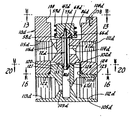
제1도는 본 발명에 따른 평행장치를 지니는 3방향솔레노니드 작동밸브의 해자위치를 도시한 단면도.1 is a cross-sectional view showing the moat position of a three-way solenoid operated valve having a parallel device according to the present invention.
제2도는 제1도의 선 2-2 부분단면도.2 is a partial cross-sectional view taken along line 2-2 of FIG.
제3도는 일부부품을 제거시킨 제1도의 선 3-3부분 단면도.3 is a cross-sectional view taken along line 3-3 of FIG. 1 with some parts removed.
제4도는 제1도의 3방향솔레노이드작동밸브의 여자위치를 도시한 단면도.4 is a cross-sectional view showing the excitation position of the three-way solenoid operated valve of FIG.
제5도는 제1도의 3방향솔레노이드 작동밸브로서 배출파이프에의 연결 나사부를 지닌 포울피이스 배출구가 제공된 상태를 도시한 단면도.FIG. 5 is a cross-sectional view of a three-way solenoid operated valve of FIG. 1 provided with a foul piece outlet having a connection thread to the discharge pipe. FIG.
제6도는 본 발명의 평행장치를 지니는 4방향솔레노이드작동 밸브의 해자위치를 도시한 단면도.6 is a cross-sectional view showing the moat position of a four-way solenoid operated valve having a parallel device of the present invention.
제7도는 제6도의 4방향솔레노이드 작동밸브의 여자위치를 도시한 단면도.FIG. 7 is a sectional view showing the excitation position of the four-way solenoid operated valve of FIG. 6. FIG.
제8도는 배출파이프의 연결나사부를 지니는 포울피이스 배출구가 제공된 제6도의 4방향솔레노이드작동 밸브의 단면도.FIG. 8 is a cross-sectional view of the six-way solenoid operated valve of FIG. 6 provided with a foul piece outlet having a connection thread of the discharge pipe.
제9도는 제8도의 선 9-9축소 배면도.9 is a back 9-9 reduction rear view of FIG.
제10도는 출ㆍ입구가 서로 다른 위치에 위치하도록 조절가능한 상ㆍ하부 몸체로 된 밸브몸체가 제공되는 본 발명을 채용한 4방향 솔레노이드 작동밸브에서 솔레노이드작동자가 일부도시된 사시도.FIG. 10 is a perspective view of the solenoid operator partially shown in a four-way solenoid operated valve employing the present invention in which a valve body having an upper and a lower body that is adjustable so that outlets and inlets are positioned at different positions is provided; FIG.
제11도는 제10도의 위치와는 다른 위치로 하부몸체가 회전한 상태를 도시한 사시도.11 is a perspective view showing a state in which the lower body is rotated to a position different from that of FIG.
제12도는 부분적으로 제거한 제10도의 선 12-12단면도.12 is a cross-sectional view taken along line 12-12 of FIG.
제13도는 제12도의 선 13-13의 상부몸체의 상부평면도.13 is a top plan view of the upper body of lines 13-13 of FIG.
제14도는 제13도의 선 14-14의 상부몸체의 후부정면도.14 is a rear elevational view of the upper body of line 14-14 of FIG.
제15도는 제13도의 선 15-15의 상부몸체의 우측면도.FIG. 15 is a right side view of the upper body of line 15-15 of FIG.
제16도는 부분적으로 제거한 제12도의 선 16-16의 상부몸체의 하부평면도.FIG. 16 is a bottom plan view of the upper body of lines 16-16 of FIG. 12 partially removed.
제17도는 제13도의 선 17-17의 상부몸체의 좌측면도.FIG. 17 is a left side view of the upper body of line 17-17 of FIG.
제18도 제13도에서 상부몸체의 선 18-18단면도.18-18 cross-sectional view 18-18 of the upper body.
제19도는 상부몸체의 솔레노이드 상부포핏시이트의 부분단면도.19 is a partial cross-sectional view of the solenoid upper poppet sheet of the upper body.
제20도는 부분적으로 제거한 제12도에서 하부몸체의 선 20-20 상부평면도.20 is a top 20-20 top plan view of the lower body, partially removed in FIG.
제21도는 제20도에서 하부몸체의 선 21-21 좌측면도.21 is a left side view of the lower body line 21-21 in FIG.
제22도는 제20도에서 하부몸체의 선 22-22 우측면도.22 is a right side view of the lower body line 22-22 in FIG.
제23도는 제20도에서 하부몸체의 선 23-23 하부평면도.23 is a bottom plan view of the lower body of FIG. 20 at line 23-23.
* 도면의 주요부분에 대한 부호의 설명* Explanation of symbols for main parts of the drawings
10 : 3방향 밸브몸체10: 3-way valve body
11 : 포울 피이스 배출구 어댑터(pole piece exhaust port adaptor)11: pole piece exhaust port adapter
12 : 솔레노이드 오퍼레이터(solenoidoperator)12: solenoid operator
15 : 솔레노이드 플런지 가이드튜브 19 : 포울 피이스15: solenoid plunge guide tube 19: foul piece
40 : 솔레노이드 하우징40: solenoid housing
47 : 솔레노이드 플런지 또는 아마츄어47: solenoid plunge or amateur
61 : 수동 오퍼레이터 68 : 흡입통로61: manual operator 68: suction passage
69 : 실린더 통로 72 : 평형장치69 cylinder passage 72 balancer
104 : 상부몸체 105 : 하부몸체104: upper body 105: lower body
본 발명은 일반적으로 밸브장치분야에 속한 것으로, 유압에 의해서 제어되는 장치, 예를들어 또 다른 밸브나 유압시린더 따위에 공기 또는 유압오일의 흐름을 제어하기 위한 3방향 또는 4방향밸브를 제공하는 것이다. 지금까지는, 솔레노이드플런지를 폐쇄위치에 유지시키는 스프링압력을 극복하기 위해서 밸브가 고압유체를 제어하는데에 사용될 때 솔레노이드 작동밸브에는 큰 솔레노이드 스러스트가 요구된다. 본 발명이 해결하고자 하는 문제점은 이와 같은 높은 솔레노이드 스러스트를 제거하는 것이며, 그 수단으로는 솔레노이드 플런저의 평형을 유지시키기 위한 독특한 평형장치를 제공하는 것입니다.The present invention generally belongs to the field of valve devices, and provides a three-way or four-way valve for controlling the flow of air or hydraulic oil, such as a hydraulically controlled device, such as another valve or hydraulic cylinder. will be. Until now, solenoid thrusts are required for solenoid thrust valves when the valve is used to control high pressure fluid to overcome the spring pressure that holds the solenoid plunger in the closed position. The problem to be solved by the present invention is to eliminate such a high solenoid thrust, and to provide a unique equalizer for balancing the solenoid plunger.
압력평형의 종래의 솔레노이드 작동 3방향 밸브의 예로는 미합중국 특허 제3,865,140호를 들 수 있읍니다. 그러나, 본 발명에서와 같이 솔레노이드 플런지 또는 아마츄어용 직결평형장치를 제공하는 것은 아니며, 탠덤 밸브 동작, 밸브오리피스 및 기타 관련 구조물을 포함하는 복잡한 유압평형구조물을 포함한다.An example of a conventional solenoid operated three-way valve of pressure balance is US Pat. No. 3,865,140. However, it does not provide a direct balancing device for solenoid plungers or amateurs as in the present invention, but includes a complex hydraulic balance structure including tandem valve operation, valve orifices and other related structures.
본 발명은 구조가 작은 평형 장치는 지닌 3방향 또는 4방향 솔레노이드 밸브를 제공하는 것이다. 본 발명에 의한 평형장치를 지닌 솔레노이드 작동밸브는 분리된 3방향 또는 4방향 제어기능용으로 사용되거나 또는 다른 밸브 예를들면 주밸브 미끄럼 스풀을 지니는 3방향 또는 4방향 밸브와 결합하여 제어하기 위해 파이로트 밸브로서 사용될 수도 있다.SUMMARY OF THE INVENTION The present invention provides a three-way or four-way solenoid valve with a small structured balancing device. Solenoid operated valves with an equalizer according to the invention are used for separate three-way or four-way control functions or pilots for controlling in combination with other valves, for example three-way or four-way valves with main valve sliding spools. It may be used as a valve.
본 발명은 솔레노이드가 해자위치 또는 여자위치에 있을때 평형을 유지하도록 솔레노이드 플런저나 아마츄어에 평형장치를 직렬시킴으로써 상술한 솔레노이드 밸브의 평형에 관한 문제를 해결한 것이다. 본 발명의 원리에 따른 4방향밸브에서는 평형장치가 솔레노이드 플런저나 아마츄어에 직렬되어 두개의 밸브 출입구 사이의 밸브를 통한 유체의 흐름을 제어하기 위한 미끄럼 스풀밸브로서의 역할을 한다. 이러한 평형장치를 지닌 솔레노이드 작동밸브의 독특한 구조에 의하여 평형을 이루는 구조로서 소형으로 될 수 있다. 또한, 본 발명의 의한 4방향 밸브의 독특한 특징은 밸브몸체를 두개의 몸체 즉 상. 하부 몸체를 구성하여 서로 상대적으로 회전가능하게 구성함으로써 실린더와 흡입구 및 배출구의 상대적인 위치를 조절할 수 있는 조절가능성을 제공하는 것이다.The present invention solves the above-mentioned problem of balancing solenoid valves by serializing a balancing device to a solenoid plunger or an amateur to maintain balance when the solenoid is in the moat or excitation position. In a four-way valve according to the principles of the present invention, an equalizer acts as a sliding spool valve for controlling the flow of fluid through a valve between two valve inlets in series with a solenoid plunger or an amateur. Due to the unique structure of the solenoid actuating valve having such a balancing device, it can be miniaturized as a balancing structure. In addition, a unique feature of the four-way valve according to the present invention is the valve body of the two bodies ie. The lower body is configured to be rotatable relative to each other to provide controllability to adjust the relative positions of the cylinder, the inlet and the outlet.
본 발명에 대하여 도면과 더불어 설명하면 다음과 같다. 제1도에는 본 발명의 에한 3방향 밸브 몸체(10)가 도시된다. 또한, 솔레노이드 오퍼레이터(12)와 포울피이스배출구어댑터(11)이 도시되며, 그 포울피이스 배출구어댑터(11)가 솔레노이드 오퍼레이터(12)의 여러부품을 고정시키고 있다. 제1 및 2도에서 솔레노이드 오퍼레이터(12)는 외부주위에 나사(17)가 난 확장된 일체의 하단부(16)를 지니는 원통형 솔레노이드플런저 가 이드튜브(15)를 지닌다. 밸브몸체(10)의 상단부에는 하항내측으로 홈이 제공되고 그 홈안에 나사(18)가 형성되어 상기 가이드튜브(15)의 나사(17)와 체결된다.The present invention will be described with reference to the drawings as follows. 1 shows a three-
제1도에 도시된 바와 같이 포울피이스(19)의 하단부가 가이드튜브(15)의 상단부에 미끄럼가능하게 장착되며, 가이드튜브(15)위로 연장된 상단부의 외주에는 나사 (20)가 형성되어 있다. 그 포울피이스(19)의 상단부 나사(20)는 배출구어댑터 (11)의 하단부에 형성된 나사구멍(21)에 체결된다. 0링(22)은 포울피이스의 상단부 나사 (20)와 나사구멍(21)사이의 나사체결부를 통하여 유체가 누출되는 것을 방지하기 위하여 나사구멍(21)에 설치된다. 또한, 0링(23)이 나사(18)에도 설치되어 가이드튜브 (15)의 하단부나사(17)와 밸브몸체(10)의 나사(18)사이의 유체의 누출을 방지한다.As shown in FIG. 1, the lower end of the
제1도에 도시된 바와같이 포울피이스(19)를 관통하여 배출구어탭터(11)의 배출통로(26)로 통하여 관형 배출통로(25)가 그 중앙에서 길이 방향으로 형성되어 있다. 그 배출통로(26)의 외측단부에는 소정의 위치로 배출되는 유체를 운반하는 배출시스템에 연결되거나 대기로 배출되는 배출구가 형성된다. 포울피이스 배출통로(25)의 하단내측단부에는 환형의 날카로운 모서리를 지니는 포핏밸브시이트(27)가 형성된다.As shown in FIG. 1, a
솔레노이드 오퍼레이터(12)는 가이드튜브(15)주위에 배치된 종래의 솔레노이드 코일(30)을 구비한다. 솔레노이드 코일(30)의 상단부는 배출구 어댑터(11)의 하단면(31)을 대향하여 놓인다. 솔레노이드 코일(30)의 하단부에는 단진 하단면(32, 33)이 제공된다. 제1도에 도시된 바와 같이 단진 하단면(32, 33)은 가이드튜브(15)의 하단부(16)의 단진상단면(34, 35)에 결합된다.The
솔레노이드 오퍼레이터(12)는 제1도에 도시된 바와 같이 솔레노이드 코일(30)의 상단부 주위에 설치된 플럭스핑(38)을 구비하는데 그 하단면을 원통형 솔레노이드 하우징(40)의 상단면(39)에 결합되며, 그 상단면은 배출구어탭터(11)의 하단면(31)에 결합된다. 제1도에 도시된 바와같이 솔레노이드 하우징(40)의 하단면(41)은 가이드튜브(15)의 하단부(16)의 단진 상단면(35)위에서 결합된다. 가이드튜브(15)의 하단부(16)의 상부상단면(34, 35)위의 제위치에서 솔레노이드 하우징(40)과 솔레노이드 코일(30) 및 플럭스링(38)을 견고하게 지지하기 위하여 그 솔레노이드 코일(30) 플럭스링(38)의 상단면에 대하여 배출구어댑터(11)가 견고한 위치로 나사체결될 때 리테이너로서 작용을 한다.The
제1도에는 솔레노이드 코일(30)용으로 통상의 전기동력 리이드 와이어(42, 43)가 도시된다.In FIG. 1, conventional
제1 및 2도에 도시된 바와 같이 솔레노이드 플런저 즉 아마츄어(47)는 스테이킹 (staking)에 의해서 거기에 고정된 원통형 슬리이브(48)를 지닌다. 솔레노이드 플런저 (47)와 슬리이브(48)는 가이드튜브(15)의 원통구멍(46)에 미끄럼가능하게 설치된다. 제 1, 2도에 도시된 바와 같이 슬리이브(48)의 전길이에 걸쳐 길이 방향으로 배출슬로트 (49)가 다수 형성된다. 그 솔레노이드 가이드 튜브(15)는 일체로 된 하단부(16)과 함께 솔레노이드 플런지(47)용 마그네틱 프레임을 포함한다.As shown in FIGS. 1 and 2, the solenoid plunger, ie, the amateur 47, has a
제1도에 도시된 바와 같이 솔레노이드 플런저(47)의 상단부에는 내측으로 구멍 (52)가 형성되며, 그 구멍(52) 아래에는 더욱 내측으로 아래방향으로 확장된 구멍 (53)이 형성된다. 또한, 제1도에 도시된 바와 같이 수직단면이 역전된 T형상인 밸브시일 (54)이 그 헤드가 구멍(52)와 (53)의 연결부에 형성된 단부에 위치되게 구멍(52)에 설치된다. 적당한 코일스프링(55)이 구멍(53)내에 설치되는데, 그 상단이 밸브시일 (54)에 접촉하며 그 하단은 구멍(53)의 내측단부벽에 접촉한다. 그 밸브시일(54)은 예를들어 탄성물질과 같은 적절한 재료로 형성된다.As shown in FIG. 1, the upper end of the
제1도에 도시된 바, 슬리이브(48)의 하단부에는 반경방향, 외측으로 플랜지 (58)가 일체로 형성되며, 그 플렌지(58)위에 플런저 복귀스프링(59)의 하단부가 위치한다. 가이드튜브(15)의 하단부(16)안에 형성된 확장된 직경의 축방향 홈(60)내에서 플런저(47), 플랜지(58)과 슬리이브(48) 및 복귀스프링(59)이 이동가능하게 설치된다. 홈(60)은 작은 직경의 구멍(46)의 하단부로 통한다. 그 복귀스프링(59)의 상단부는 구멍(46)과 확대된 구멍(60)의 교차점에서 형성되는 단부에 설치된다. 아래에 상설되는 바와같이 밸브몸체 (10)에 형성된 밸브시이트(66)와 결합되게 솔레노이드 플런저 (47)의 하단부에 구비된 밸브시일(64)에 결속되도록 복귀스프링(59)은 정상상태에서 솔레노이드 플런저(47)를 아래방향으로 가압한다. 수동 오퍼레이터(61)는 솔레노이드 플런저(47)를 수동으로 위쪽으로 이동시켜 밸브시일(64)을 밸브시이트(66)에서 벗어나게 한다.As shown in FIG. 1, a
제1도에서 밸브몸체(10)에는 솔레노이드 플런저(47)의 축방향으로 위치되는 축방향구멍(67)이 제공된다. 축방향구멍(67)은 밸브시이트(66)로부터 밸브몸체 ( 10)속 아래로 연장된다. 흡입통로(68)가 밸브몸체(10)를 관통하여 형성되고, 그 내측단부는 축방향구멍(67)으로 통하며, 그 외측단부는 밸브몸체(10)의 외부로 통하여 흡입구로서 작용한다. 흡입통로(68)는 예를들어 가압된 공기원과 같은 압력하의 유체원에 연결된다. 실린더통로(69)도 흡입통로(68)위의 제위치에 밸브몸체(10)를 관통하여 형성된다. 그 실린더 통로(69)는 밸브몸체(10)내의 구멍(86)과 그 내측단부에서 통한다. 구멍(86)은 가이드튜브의 하단부(16)내의 구멍(60)으로 그 상단부에서 통한다. 실린더 통로(69)는 또한 같은 작용을 하기 위하여 압력유체를 공급하는 장치에 연결되는 실린더 연결구로서 작용한다.In FIG. 1, the
제1도에서, 솔레노이드 평형장치(72)는 축방향구멍(67)내에서 축방향 이동가능하게 설치된다. 그 솔레노이드 평형장치(72)는, 상단부에 일체의 확대된 환형플랜지 (74)가 제공된 긴 축(73)을 구비하는 긴 평형스풀을 포함한다. 나사축(75)가 플랜지 (74)의 상단부에 일체로 형성된다. 그 나사축(75)은 밸브시일(64)의 구멍(77)에 설치되며 솔레노이드 플런저(47)의 하단부의 나사구멍(76)에 체결된다. 나사축(75)가 견고하게 체결될 때 플랜지(74)는 밸브시일(64)의 중앙위치에 위치하여 밸브시이트 (66)과 결합하는 밸브시일(64)의 부분에서 내측에 위치하게 된다.In FIG. 1, the solenoid balancer 72 is installed to be axially movable in the axial hole 67. The solenoid balancer 72 includes an elongate balance spool having an
제1도에서와 같이, 평형장치의 축(73)은 그 하단부에 일체로 된 한 쌍의 길이방향으로 떨어져 있는 플랜지(80)를 구비하며, 그 사이에는 0링(81)이 미끄럼작동 가능하게 설치된다. 배출구(82)가 밸브몸체(10)을 관통하여 형성되어 축(73)의 하부플랜지(80)아래에 구멍(67)의 하단부가 밸브몸체(10)밖으로 통하게 된다.As in FIG. 1, the
제1도에 도시된 밸브의 상태는 해자상태이다. 제1도에서 솔레노이드 플런저 (47)는 평형상태에 있게 되는데, 그 이유는 평형장치의 0링(81)의 하단부직경이 밸브시일(64)에 의해 폐쇄된 밸브시이트(66)의 직경과 동일하기 때문이다. 이 평형작용을 통하여 솔레노이드 오퍼레이터(12)의 복귀스프링(59)이 약한 스러스트 작용을 하게 되는데, 그 이유는 밸브의 해자시 밸브시이트(66)상에서 밸브시일(64)을 제워치에 유지시키기 위하여 구멍(67)내의 유압을 극복할 필요가 없기 때문이다.The state of the valve shown in FIG. 1 is a moat state. In FIG. 1 the
제1, 3도에서 수동 오퍼레이터(61)가 회전가능하게 설치되는 구멍(85)이 밸브몸체(10)에 제공된다. 그 수동 오퍼레이터(61)에는 구멍(85)내에서 회전가능하게 설치된 원통형 몸체가 포함되며, 그 몸체의 외측단부에는 수동오퍼레이터(61)를 회전시키는 공구를 삽입시키기 위한 슬로트(88)가 제공된다. 그 수동오퍼레이터(61)과 일체로 내측단부에 편심원통 캠(87)이 형성되어 있어서, 그 캠(87)이 플랜지(58)에 결속되게 위쪽으로 이동되는 방향으로 수동오퍼레이터(61)가 회전될 때 솔레노이드 플런저 (47)의 플랜지 (58)의 바닥부(89)가 맞다아 위쪽으로 이동된다. 고정 나사 (90)가 밸브몸체(10)에 구멍 (85)속으로 길이방향아래로 형성된 나사구멍(91)에 체결된다. 그 고정나사(90)가 수동 오퍼레이터(61)의 원통몸체의 외부표면에 형성된 원주홈에 결합되어 수동오퍼레이터 (61)의 길이방향이동을 저지 시키며 회전만 가능하게 한다. 또한, 0링(62)가 그 원주홈에 설치된다.In the first and third degrees, the
제1도의 해자위치에서 흡입구(68)로 들어온 유체는 축방향구멍(67)을 통과한 후 하부밸브시일(64)이 밸브시이트(66)위에 위치함으로써 실린더 통로(69)로 흘러들어가지 못한다. 평형장치(72)의 하단플랜지(80)와 0링(81)과 밸브시일(64)에 같은 유압이 작용하여 제1도에서와 같이 솔레노이드 플런저(47)가 평형일 이룬다. 제1도의 위치에서 실린더 통로(69)는, 구멍(60)과 (86)의 연결통로에 의해서, 또 슬로트(49), 솔레노이드 플런저(47)의 상단부의 구멍(46) 및 배출통로(26)에의 연결통로(25)를 통하여 배출통로(26)로 통한다.Fluid entering the inlet 68 in the moat position of FIG. 1 does not flow into the
솔레노이드 오퍼레이터(12)가 여자되면, 솔레노이드 플런저(47)가 상향으로 이동하여 하부 밸브시일(64)를 하부밸브시이트(66)에서 떨어져 위로 올라가게 하고 상부밸브시일(50)를 상부 밸브시이트(27)에 위치하게 한다. 제4도의 위치에서 실린더 통로 (69)에서 배출통로(26)에로의 배출통로는 폐쇄된다. 그러나 압력유체는 흡입통로 (68)로 부터 축방향구멍(67)과 개방된 하부밸브시이트(66) 및 구멍(86)을 통하여 실린더통로 (69)로 흐른다. 솔레노이드 오퍼레이터(12)가 해자하면 솔레노이드 플런저 (47)는 복귀스프링(59)의 작동으로 제1도의 해자위치로 복귀한다.When the
제5도에서는 제1-4도의 3방향밸브와 거의 유사하지만 파이프를 연결할 수 있도록 나사부가 제공된 3방향밸브가 도시된다. 제5도에서는 제1-4도에서 사용된 부호에 ″a″를 첨가하여 사용한다. 제5도의 실시예에서는 제1도에서의 배출어댑터(11)대신에 나사체결 고정너트(95)가 포울피이스(19a)의 숫나사부(20a)에 체결되어 제1-4도의 제1실시예에서의 배출어탭터(11)에서와 같은 방법으로 솔레노이드 오퍼레이터 (12a)의 여러 부품을 제위치에 고정시키는 기능을 한다. 적절한 0링(98)은 너트(95)내와 포울피이스(19a)의 나사부(20a)주위의 가이드튜브(15)의 상단부 인접위치에 설치된다. 배출통로 (25a)의 상단부로 통하는 암나사를 지니는 출구통로(99)가 포울피이스(19a)의 상단부 외측으로 제공된다.FIG. 5 shows a three-way valve that is similar to the three-way valve of FIGS. 1-4 but provided with a threaded portion for connecting pipes. In FIG. 5, ″ a ″ is added to the code used in FIGS. 1-4. In the embodiment of FIG. 5, instead of the
압력유체흡입통로(68a)는 그 외측단부에서 확장되고 나사가 난흡입구(69)로 통한다. 그 실린더통로(69a)는 그 외측단부에서 나사가 난 실린더 출구(97)로 통한다.The pressure
제5도의 3방향밸브는 제1-4도에서 상술된 바와 같은 기능을 한다.The three-way valve of FIG. 5 functions as described above in FIGS. 1-4.
제6, 7도에서는 본 발명에 의한 4방향밸브를 도시한다.6 and 7 show a four-way valve according to the present invention.
제6, 7도의 부품에서는 제1-4도와같은 부호에 ″b″를 첨부하여 도시한다.Parts shown in Figs. 6 and 7 are shown with the same symbol as " b " shown in Figs. 1-4.
제6, 7도에서는 밸브몸체(10)가 상부몸체(104)와 하부몸체(105)로 두부분으로 구성된다. 하부몸체(105)의 상면에는 환형보스 즉 돌출부(108)가 형성되어 있어서 상부몸체(104)의 하면에 형성된 환형 홈(109)내에 회전가능하게 결합된다. 하부몸체 (105)의 적당한 구멍을 관통하여 상부몸체(104)의 하단부에 형성된 나사구멍에 체결되는 다수의 적당한 나사(106)에 의해서 상. 하부 몸체(105) (106)가 분해가능하게 고정된다.6 and 7, the
제6도에 도시된 바와같이, 제2실린더통로(100)는 상부몸체(104)의 흡입통로 (68b)위치에 형성된다. 제2실린더통로(100)는 개구(101)를 통하여 하부몸체(105)의 보스 (108)에 형성된 횡단환형 챔버(102)로 통한다. 환형챔버(102)는 평형장치 ( 72b)가 미끄럼 가능하게 설치되는 축방향 구멍(67b)로 통한다.As shown in FIG. 6, the
제6도에서 제2배출구통로(103)는 하부몸체(105)에 형성되며 평형장치(72b)아래위치에서 축방향구멍(67b)의 하단부로 통한다. 적당한 0링(107)이 상부몸체 (104)의 하면의 환형홈에 설치되어 하부몸체(105)의 상면과의 밀봉작용을 한다.In FIG. 6, the
제6도에서는 4방향 밸브의 해자위치가 도시되고 제7도에서는 4방향밸브의 여자위치가 도시된다. 제6도의 해자위치에서 솔레노이드 플런저(47b)는 제1-4도의 제1실시예에서 설명된 바와같은 이유로 평형상태에 있게 된다. 흡입통로(68b)는 밸브시이트 (66b)위에 위치한 밸브시일(64b)와 평형장치(72b)의 하단부 사이의 축방향 구멍(67b)으로 압력유체가 흐른다. 그 압력유체는 흡입통로(68b)로 부터 축방향 구멍 (67b), 통로 즉 챔버(102), 개구(101) 및 제2실린더 통로(100)을 통과하며 그 압력 유체에 의해서 제어되는 장치로 흐른다. 제1실린더 통로(69b)는 해자외치에서 제1도에서 설명한 바와같이, 배출통로(26b)로 연결된다. 솔레노이드 오퍼레이터(12b)의 여자시, 그 솔레노이드(47b)는 제7도에서의 위치로 상향이동하여, 밸브시이트(27b)위에 상부밸브시일(54b)을 위치시켜 흡입통로(26b)를 폐쇄한다. 제1실린더 통로(69b)는 상부몸체(104)의 밸브시이트 (27b)를 통하여 축방향구멍(67b)로 연결된다. 그때 유체는 그 유체에 의해서 제어되는 장치에로 전달되기 위해서 바로 위에서 설명된 통로를 통하여 흡입통로(68b)로 부터 제1실린더통로(69b)속으로 흐른다. 제2실린더 통로 ( 100)는 개구(101), 홈(102) 및 축방향 구멍(67b)의 하단부를 통하여 제2배출통로 (103)로 연결된다.In FIG. 6 the moat position of the four-way valve is shown and in FIG. 7 the excitation position of the four-way valve is shown. In the moat position of FIG. 6, the solenoid plunger 47b is in equilibrium for the reasons described in the first embodiment of FIGS. The suction passage 68b flows pressure fluid into an axial hole 67b between the valve seal 64b located on the valve seat 66b and the lower end of the balancer 72b. The pressure fluid flows from the suction passage 68b through the axial hole 67b, the passage ie the
제6, 7도에서 평형장치(72b)는 평형장치로서뿐만 아니라 미끄럼 밸브 스풀로서도 작용을 한다. 솔레노이드 오퍼레이터(12b)의 해자시, 4방향밸브를 통하여 유체가 역류하도록 복귀스프링(59b)은 솔레노이드 플런저(47b)를 제6도의 초기위치로 복귀시킨다.6 and 7 the balancer 72b acts not only as the balancer but also as a sliding valve spool. Upon dissolving the solenoid operator 12b, the return spring 59b returns the solenoid plunger 47b to the initial position of FIG. 6 so that the fluid flows back through the four-way valve.
하부몸체(105)는 제6, 7도의 위치로부터 회전하여 새로운 위치로 이동될 수 있다. 아래 제11-23도에서 설명되는 바와같이 어떤 소정의 조절된 회전위치에 하부몸체 (105)를 고정시키는 데에 나사(106)를 사용할 수 있는 위치에서 상부몸체의 하단부에 나사구멍을 제공함으로써 상술된 하부몸체(105)의 회전이 가능하다.The
제8, 9도는 본 발명의 또다른 4방향밸브를 도시한다. 제8, 9도에서는 제1-4도 또는 제5도나 또는 제5도나 제6, 7도에서와 같은 부호에 ″C″를 첨부하여 도시한다. 제6, 7도와 제8, 9도에서 도시되는 4방향 밸브의 차이는 실린더 통로와 흡입통로 및 하나의 배출통로가 서로 90도를 이루며, 포울피이스(19c)의 배출통로에는 암나사가 형성되고, 포울피이스(19c)가 제1도의 실시예에서 채용된것과 동일한 고정너트 구조에 의해서 지금까지 설명된 바와같은 위치에 유지된다.8 and 9 show another four-way valve of the present invention. 8 and 9 show the same reference numerals as those in FIGS. 1-4 or 5 or 5 or 6 and 7. The difference between the four-way valves shown in FIGS. 6, 7 and 8 and 9 is that the cylinder passage, the suction passage and one
제8, 9도의 실시예에서는 상부몸체(104c)와 하부몸체(105c)가 L형상의 선을 따라 상부몸체(104c)의 L형상(116)과 하부몸체(105c)의 L형상(117)이 결합된다. 하부몸체 (105c)는 다수의 적당한 나사(106c)에 의해서 상부몸체(104c)에 해체 가능하게 고정된다.8 and 9, the upper body 104c and the lower body 105c form the
제8도에서, 제2실린더 통로(100c)는 나사가난 실린더포트(112)로 통한다. 그 제2배출통로(103c)는 나사가난 배출구(113)으로 통한다. 제2실린더포트(112)와 제2배출구(113)는 제8, 9도에서와 같이 서로 대향위치에 배치된다. 제9도에서와 같이 흡입통로(68c)는 제1실린더통로(69c)로 연결된 제1실린더포트(115)의 대향위치에 있는 나사가난 흡입구(111)로 통한다. 제1실린더포트(115)는 제8도에 도시되지 않는다. 그러나, 제1실린더 통로(69c)는 흡입구(111)과 같은 높이에서 구멍(86c)로 위쪽으로 통하는 실린더포트(115)로 부터 위로 형성된다.In FIG. 8, the second cylinder passage 100c leads to the threaded
제8도의 4방향밸브는 제6, 7도의 4방향밸브나 동일한 기능을 한다. 제8도의 위치에 솔레노이드 오퍼레이터(12c)는 해자 위치에 있으며, 실린더 포트(112)는 평형장치와 밸브스풀(80c, 81c)에 의해서 배출구(113)로의 통로가 차단된다. 실린더포트 (112)에 흡입구(111)에서 공급되는 압력유체가 축방향 구멍(67c)로부터 공급되는 동안, 실린더포트(115)는 배출구(99c)로 열린다. 솔레노이드 오퍼레이터(12c)의 여자시, 솔레노이드 플런저(47c)는 상향으로 이동하여, 실린더포트(112)에서 배출구 (11 3)를 통하여 배출되는 동안, 배출통로(99c)는 차단되고 축방향구멍(67c)는 구멍 (86c)으로 통하게 되고 압력유체는 실린더포트(115)로 흘러들어간다.The four-way valve of FIG. 8 functions the same as the four-way valve of FIGS. 6 and 7. In the position of FIG. 8, the
제10-23도는 본 발명의 또다른 실시예를 도시하는데, 그 4방향파이프 밸브는 그 밸브몸체가 상부 및 하부몸체의 2개로 구성되며, 그 상. 하부몸체가 서로 다른 위치로 회전할 수 있어서, 그 밸브에 하나의 밸브몸체를 제공하거나 특수한 위치에 출구를 구비한 필요없이 여러가지 다른 최적위치에서 다양한 출구가 사용될 수 있다. 제10-23도에서의 도면부호는 전술한 것과 동일하나 ″d″문자가 첨부된다. 제10, 11도에서 솔레노이드 오퍼레이터(12d)는 동일한 구조이며 전술한 실시예에서와 같은 기능을 한다. 상부몸체 (104d)는 블럭형상이며, 유사한 블럭형상인 하부몸체(105d)와 결합된다.10-23 show another embodiment of the present invention wherein the four-way pipe valve has a valve body consisting of two upper and lower bodies. The lower body can rotate to different positions, so that various outlets can be used at various different optimum positions without the need to provide one valve body to the valve or to have the outlet at a particular position. Reference numerals in Figs. 10-23 are the same as those described above, but are appended with the letter ″ d ″. 10 and 11, the solenoid operator 12d has the same structure and functions the same as in the above-described embodiment. The
제12, 20-22도에서 가장 잘 도시된바, 하부몸체(105d)에는 그 상단부에 축방향 일체로된 보스 즉 피봇축(120)에 제공된다. 제12도에서 상부몸체(104d)에는 그 하단부에 축방향 피봇홈 즉 챔버(121)가 하부밸브(105d)위에 보스(120)를 회전가능하게 수용하도록 제공된다. 적당한 0링(122)이 보스(120)의 하단부와 피봇홈(121)의 외측 단부사이에 제공된다. 제12도의 조립상태에서 상부몸체(104d)의 하면(123)은 하부몸체(105d)의 상면(124)위에 회전가능하고 미끄럼가능하게 설치된다. 제12도에서와 같이, 유체 전달통로(102d)를 형성하기 위해서 환형피봇홈(121)의 내측단부벽 (128)은 피봇보스(120)의 상단(133)으로부터 떨어져 있다. 제13도에 도시된바, 솔레노이드 오퍼레이터(12d)로부터 상부몸체(104d)에 형성된 나사가난 구멍(138)속 아래로 연장되는 적당한 한쌍의 나사(137)에 의해서와 같이 적당한 수단에 의해서 상부몸체(104d)는 솔레노이드 오퍼레이터(12d)에 해체가능하게 연결된다. 제12도에도 또한 나사가 난 구멍(138)의 하나가 도시된다. 제10, 16도에서와 같이, 하부몸체(105d)의 나사가 난 구멍(134)(제23도)을 관통하여 상부몸체(104d)의 하단부에 형성된 4개의 나사구멍(130) (제16도)중의 두개의 나사체결되는 적당한 산쌍의 나사(129)에 의해서 하부몸체(105d)는 상부몸체(104d)에 해체가능하게 고정된다. 제12, 13, 18도에서와 같이, 구멍(139)은 솔레노이드 오퍼레이터 (12d)의 하단부를 수용한다.As best shown in FIGS. 12 and 20-22, the
제10-23도의 4방향밸브는 제8, 9도에서 설명된 것과 같은 기능을 한다. 그러나, 나사(129)가 하부몸체(105a)에서 제거된 뒤 흡입구(111d)와 제1실린더포트 (115d)에 대하여 상대적으로 각각 다른위치에 제2실린더포트(112d)와 제2배출구 (113d)를 위치시키기 위하여 하부밸브(105d)가 4개의 선택가능한 위치중의 한 위치로 회전될 수 있다는 점에서 제10-23도의 4방향밸브가 더욱 유용성이 있다. 그뒤 나사(129)는 그 선택된 위치에서 하부 몸체(105d)를 유지시키도록 체결된다.The four-way valves of FIGS. 10-23 also function as described in FIGS. 8 and 9. However, after the
제1-23도에 사용된 적당한 솔레노이드 오퍼레이터는 Nass Magnet GmbH (Postfach 4327, D-3000 Hannover 1)사 TYP 054302 4.0이 시장에서 구할 수 있는 유용한 것중, 하나이다.A suitable solenoid operator used in FIGS. 1-23 is one of the useful tools available on the market by TYP 054302 4.0 from Nass Magnet GmbH (Postfach 4327, D-3000 Hannover 1).
또한 모든 4방향 밸브에 사용되는 유체 전달통로(102)는 중간 유체전달 챔버로서 청구범위에 기재된다.
본 발명의 독특한 특징은 평형장치(72)와 솔레노이드 플런저(47)가 같은 크기의 3방향과 4방향 밸브에서 같은 길이방향 거리를 이동한다.A unique feature of the present invention is that the balancer 72 and
본 발명의 전 실시예에서 솔레노이드 플런저(47)는 여자위치에서 평형을 유지한다. 상부 밸브시일(54)이 배출통로의 밸브시이트(27)위에 놓일때 유효한 밀봉작용을 하는 직경(28)에 의해서 상기 특징이 제4도의 제1실시예에서 도시된다. 축방향 구멍(67)의 직경이 밀봉작용을 하는 직경(28)과 동일하기 때문에 평형작용이 유지된다.In all embodiments of the present invention the
Claims (8)
Applications Claiming Priority (2)
| Application Number | Priority Date | Filing Date | Title |
|---|---|---|---|
| US677,214 | 1984-12-03 | ||
| US06/677,214 US4598736A (en) | 1984-12-03 | 1984-12-03 | Solenoid operated valve with balancing means |
Publications (2)
| Publication Number | Publication Date |
|---|---|
| KR860005177A KR860005177A (en) | 1986-07-18 |
| KR890001019B1 true KR890001019B1 (en) | 1989-04-18 |
Family
ID=24717794
Family Applications (1)
| Application Number | Title | Priority Date | Filing Date |
|---|---|---|---|
| KR1019850009060A KR890001019B1 (en) | 1984-12-03 | 1985-12-03 | Solenoid operated valve wite balancing device |
Country Status (15)
| Country | Link |
|---|---|
| US (1) | US4598736A (en) |
| JP (2) | JPS61136075A (en) |
| KR (1) | KR890001019B1 (en) |
| CN (1) | CN1011734B (en) |
| AU (1) | AU557748B2 (en) |
| BR (1) | BR8506022A (en) |
| CA (1) | CA1213812A (en) |
| CH (1) | CH666335A5 (en) |
| DE (1) | DE3524639A1 (en) |
| ES (1) | ES8700404A1 (en) |
| FR (1) | FR2574149B1 (en) |
| GB (1) | GB2167835B (en) |
| IT (1) | IT1209949B (en) |
| MX (1) | MX162578A (en) |
| SE (1) | SE463435B (en) |
Families Citing this family (39)
| Publication number | Priority date | Publication date | Assignee | Title |
|---|---|---|---|---|
| GB2185090A (en) * | 1985-12-16 | 1987-07-08 | Amtrol Inc | Improved control valve for water pump system |
| US4727899A (en) * | 1986-10-16 | 1988-03-01 | Parker & Harper Manufacturing Company, Inc. | Pilot valve assembly |
| US4693275A (en) * | 1986-11-28 | 1987-09-15 | General Motors Corporation | Electro-hydraulic pressure regulating valve |
| US4770210A (en) * | 1987-07-23 | 1988-09-13 | Mac Valves, Inc. | Valve manifold stacking base |
| US4770209A (en) * | 1987-07-23 | 1988-09-13 | Mac Valves, Inc. | Valve base with integral flow controls |
| DE3732445C2 (en) * | 1987-09-25 | 1993-12-23 | Rexroth Mannesmann Gmbh | Pressure control valve |
| US4821774A (en) * | 1988-04-04 | 1989-04-18 | Chorkey William J | Solenoid operated valve with balancing means |
| DE58909504D1 (en) * | 1989-01-28 | 1995-12-21 | Kuhnke Gmbh Kg H | Balanced lift valve. |
| US5204652A (en) * | 1990-11-20 | 1993-04-20 | National Irrigation Specialists, Inc. | Adjustable bleed system for a universal solenoid for fluid control valves |
| US5088520A (en) * | 1991-05-20 | 1992-02-18 | South Bend Controls, Inc. | Modular solenid valve |
| US5351934A (en) * | 1992-12-15 | 1994-10-04 | Alliedsignal, Inc. | Proportional solenoid valve |
| DE69427655T2 (en) * | 1993-03-19 | 2001-10-18 | Cummins Engine Co Inc | Pressure balanced three-way solenoid valve |
| DE69400242T2 (en) * | 1993-03-31 | 1996-10-10 | Cummins Engine Co Inc | Compact three-way valve with a mandrel in a sleeve |
| DE4416279A1 (en) * | 1994-05-07 | 1995-11-16 | Grau Gmbh | magnetic valve |
| US5518030A (en) * | 1994-12-12 | 1996-05-21 | Cummins Engine Company, Inc. | Three-way flow valve with variable drain orifice area |
| US6379538B1 (en) | 1997-06-05 | 2002-04-30 | Lucid Treatment Systems, Inc. | Apparatus for separation and recovery of liquid and slurry abrasives used for polishing |
| KR100349851B1 (en) * | 1999-12-06 | 2002-08-22 | 현대자동차주식회사 | Injector lowering emission gas |
| US6832748B2 (en) * | 2001-12-05 | 2004-12-21 | Cummins Inc. | Outwardly opening, seat-sealed, force balanced, hydraulic valve and actuator assembly |
| JP4092625B2 (en) * | 2002-06-11 | 2008-05-28 | Smc株式会社 | Manual operation device of solenoid valve |
| DE10232554B4 (en) * | 2002-07-18 | 2004-05-19 | Haldex Brake Products Gmbh | Solenoid valve for commercial vehicles with air suspension |
| CN1890451B (en) * | 2003-11-07 | 2010-12-08 | Aps技术公司 | System and method for damping vibration in a drill string |
| US7458395B2 (en) * | 2004-06-07 | 2008-12-02 | Borgwarner Inc. | Low leak poppet solenoid |
| US8167000B2 (en) * | 2007-04-05 | 2012-05-01 | Mac Valves, Inc. | Balanced solenoid valve |
| US8151824B2 (en) * | 2007-04-05 | 2012-04-10 | Mac Valves, Inc. | Balanced solenoid valve |
| DE102008035961A1 (en) * | 2008-07-31 | 2010-02-04 | Schaeffler Kg | Thermal management module of the cooling system of an internal combustion engine |
| DE102010025175A1 (en) * | 2010-06-25 | 2011-12-29 | Pierburg Gmbh | Infinitely adjustable pressure control valve |
| US9010373B2 (en) | 2010-09-09 | 2015-04-21 | Mac Valves, Inc. | Pressure balanced valve with diaphragm valve member end seal |
| US9074699B2 (en) * | 2012-12-21 | 2015-07-07 | Mac Valves, Inc. | Multi-port normally open modular valve with thread-in seat |
| US8783653B2 (en) | 2012-12-21 | 2014-07-22 | Mac Valves, Inc. | Multi-port modular valve with snap-in seat |
| US9022069B2 (en) | 2013-03-15 | 2015-05-05 | Mac Valves, Inc. | Solenoid operated valve with constant bleed port |
| JP6212463B2 (en) * | 2014-10-02 | 2017-10-11 | 高砂電気工業株式会社 | Small solenoid valve |
| DE102015101477B4 (en) * | 2015-02-02 | 2022-02-17 | Pierburg Gmbh | Electromagnetic valve for the automotive sector |
| US10993546B2 (en) | 2016-10-28 | 2021-05-04 | Sleep Number Corporation | Noise reducing plunger |
| US10473229B2 (en) | 2017-09-25 | 2019-11-12 | Mac Valves, Inc. | Diaphragm valve |
| US11028837B2 (en) | 2019-01-29 | 2021-06-08 | Mac Valves, Inc. | Solenoid pump |
| CN110864151A (en) * | 2019-11-28 | 2020-03-06 | 徐州蓝格数字科技有限公司 | Intelligent electromagnetic valve for signal conversion |
| WO2022147345A1 (en) * | 2021-01-02 | 2022-07-07 | Dayco Ip Holdings, Llc | Magnetically latching valve for fuel vapor management systems and systems incorporating same |
| CN116783417B (en) * | 2021-01-02 | 2024-04-05 | 戴科知识产权控股有限责任公司 | Magnetic latching valve for fuel vapor management system and system including the same |
| US11832728B2 (en) | 2021-08-24 | 2023-12-05 | Sleep Number Corporation | Controlling vibration transmission within inflation assemblies |
Family Cites Families (20)
| Publication number | Priority date | Publication date | Assignee | Title |
|---|---|---|---|---|
| GB601172A (en) * | 1945-07-09 | 1948-04-29 | William Robert Steele | Electrically operated remotely controlled valves |
| GB360978A (en) * | 1930-08-15 | 1931-11-16 | Joseph Leslie Musgrave | Combined mechanically and electro-magnetically operated valve |
| GB372479A (en) * | 1931-03-14 | 1932-05-12 | Joseph Leslie Musgrave | Improvements in connection with electro-magnetic valves |
| US2934090A (en) * | 1955-11-25 | 1960-04-26 | Marotta Valve Corp | Three-way magnetic valve |
| CH331648A (en) * | 1956-07-23 | 1958-07-31 | Charles Dubois Roger | Electromagnetic valve for fluids at all pressures |
| US3016920A (en) * | 1957-08-06 | 1962-01-16 | Specialties Dev Corp | Solenoid operated valve unit |
| GB889987A (en) * | 1957-09-18 | 1962-02-21 | Climax Rock Drill & Engineering Works Ltd | Improvements in electrically-operated pnuematic valves |
| GB868896A (en) * | 1959-03-23 | 1961-05-25 | Gen Controls Co | Solenoid valve |
| DE1143685B (en) * | 1960-04-06 | 1963-02-14 | Erich Herion | Four-way solenoid valve |
| US3236494A (en) * | 1962-04-23 | 1966-02-22 | White Sales Corp Graham | Manually operable solenoid valve |
| DE1165955B (en) * | 1962-09-08 | 1964-03-19 | Erich Herion | Multi-way valve, especially solenoid valve |
| JPS474460U (en) * | 1971-02-04 | 1972-09-11 | ||
| GB1413112A (en) * | 1971-10-28 | 1975-11-05 | Dowty Mining Equipment Ltd | Hydraulic valve |
| GB1338270A (en) * | 1971-10-29 | 1973-11-21 | Yamato Sangyo Co Ltd | Fluid flow control valves |
| DE2158248C2 (en) * | 1971-11-24 | 1982-11-04 | Bürkert GmbH, 7118 Ingelfingen | Multipath manually operated magnetic valve - has non-central turnable actuating pin and leaf spring to lift armature |
| CA1021225A (en) * | 1974-06-28 | 1977-11-22 | General Signal Corporation | Quick-acting valve assembly |
| US3963048A (en) * | 1975-02-27 | 1976-06-15 | General Gas Light Company | Poppet valve assembly |
| US3985333A (en) * | 1975-09-02 | 1976-10-12 | Spraying Systems Co. | Solenoid valve |
| US4026325A (en) * | 1976-03-01 | 1977-05-31 | General Gas Light Company | Miniature four-way valve |
| GB2094441A (en) * | 1981-03-10 | 1982-09-15 | Lindley Ltd H | Valves |
-
1984
- 1984-12-03 US US06/677,214 patent/US4598736A/en not_active Expired - Fee Related
-
1985
- 1985-03-07 GB GB08505888A patent/GB2167835B/en not_active Expired
- 1985-03-20 CA CA000477040A patent/CA1213812A/en not_active Expired
- 1985-04-11 IT IT4794785A patent/IT1209949B/en active
- 1985-04-30 JP JP60091329A patent/JPS61136075A/en active Pending
- 1985-06-03 SE SE8502738A patent/SE463435B/en not_active IP Right Cessation
- 1985-07-02 FR FR8510100A patent/FR2574149B1/en not_active Expired
- 1985-07-10 DE DE19853524639 patent/DE3524639A1/en active Granted
- 1985-11-27 AU AU50430/85A patent/AU557748B2/en not_active Ceased
- 1985-11-29 CH CH5097/85A patent/CH666335A5/en not_active IP Right Cessation
- 1985-12-02 BR BR8506022A patent/BR8506022A/en not_active IP Right Cessation
- 1985-12-02 ES ES549486A patent/ES8700404A1/en not_active Expired
- 1985-12-02 CN CN85109390A patent/CN1011734B/en not_active Expired
- 1985-12-03 KR KR1019850009060A patent/KR890001019B1/en not_active IP Right Cessation
- 1985-12-09 MX MX873A patent/MX162578A/en unknown
-
1991
- 1991-07-01 JP JP5053191U patent/JPH0488784U/ja active Pending
Also Published As
| Publication number | Publication date |
|---|---|
| JPS61136075A (en) | 1986-06-23 |
| IT1209949B (en) | 1989-08-30 |
| SE463435B (en) | 1990-11-19 |
| IT8547947A0 (en) | 1985-04-11 |
| GB2167835A (en) | 1986-06-04 |
| ES8700404A1 (en) | 1986-10-01 |
| AU5043085A (en) | 1986-06-12 |
| AU557748B2 (en) | 1987-01-08 |
| BR8506022A (en) | 1986-08-19 |
| FR2574149B1 (en) | 1987-02-13 |
| JPH0488784U (en) | 1992-07-31 |
| KR860005177A (en) | 1986-07-18 |
| CN85109390A (en) | 1986-10-22 |
| GB8505888D0 (en) | 1985-04-11 |
| CA1213812A (en) | 1986-11-12 |
| SE8502738L (en) | 1986-06-04 |
| DE3524639C2 (en) | 1992-01-02 |
| SE8502738D0 (en) | 1985-06-03 |
| DE3524639A1 (en) | 1986-06-05 |
| FR2574149A1 (en) | 1986-06-06 |
| GB2167835B (en) | 1989-01-05 |
| US4598736A (en) | 1986-07-08 |
| CH666335A5 (en) | 1988-07-15 |
| ES549486A0 (en) | 1986-10-01 |
| MX162578A (en) | 1991-05-27 |
| CN1011734B (en) | 1991-02-20 |
Similar Documents
| Publication | Publication Date | Title |
|---|---|---|
| KR890001019B1 (en) | Solenoid operated valve wite balancing device | |
| KR890001017B1 (en) | Four-way poppet valve | |
| KR100283611B1 (en) | Speed controller with pilot check valve and fluid pressure control circuit to which it is applied | |
| US4167262A (en) | Pilot actuated valve | |
| US5361431A (en) | Vacuum breaker for faucets | |
| EP0058559B1 (en) | Improved valve | |
| US3215163A (en) | Two-position, four-way pilot operated valve | |
| US3565115A (en) | Spool valve | |
| JP3201480B2 (en) | Screw-in valve | |
| AU2001282863B2 (en) | Four way valve | |
| US4494572A (en) | Four-way poppet valve assembly | |
| US4901976A (en) | Flow control valve | |
| EP0461331B1 (en) | Three way valve | |
| JPH0231007A (en) | Hydraulic drive | |
| US4056119A (en) | Solenoid valve | |
| US20050150560A1 (en) | Diaphragm valve | |
| US4901755A (en) | Valve housing for cartridge type faucets | |
| US4002070A (en) | Sample injection system | |
| CA2101394C (en) | Mixing valve | |
| US3709254A (en) | Valve assembly for water fountains and the like | |
| WO1985003556A1 (en) | A pneumatic servo valve (governing valve) | |
| CN218063476U (en) | Flow regulating valve | |
| JPS63130903A (en) | Actuator driving system | |
| US3533445A (en) | Multiple passage spool valve having stepped bore | |
| US20100126611A1 (en) | Three-position diverter valve |
Legal Events
| Date | Code | Title | Description |
|---|---|---|---|
| A201 | Request for examination | ||
| G160 | Decision to publish patent application | ||
| E701 | Decision to grant or registration of patent right | ||
| GRNT | Written decision to grant | ||
| FPAY | Annual fee payment |
Payment date: 19920323 Year of fee payment: 4 |
|
| LAPS | Lapse due to unpaid annual fee |