KR890000774B1 - Gun mount - Google Patents
Gun mount Download PDFInfo
- Publication number
- KR890000774B1 KR890000774B1 KR8203693A KR820003693A KR890000774B1 KR 890000774 B1 KR890000774 B1 KR 890000774B1 KR 8203693 A KR8203693 A KR 8203693A KR 820003693 A KR820003693 A KR 820003693A KR 890000774 B1 KR890000774 B1 KR 890000774B1
- Authority
- KR
- South Korea
- Prior art keywords
- axis
- ring
- fixed
- base
- carriage
- Prior art date
Links
Images


Classifications
-
- F—MECHANICAL ENGINEERING; LIGHTING; HEATING; WEAPONS; BLASTING
- F41—WEAPONS
- F41A—FUNCTIONAL FEATURES OR DETAILS COMMON TO BOTH SMALLARMS AND ORDNANCE, e.g. CANNONS; MOUNTINGS FOR SMALLARMS OR ORDNANCE
- F41A27/00—Gun mountings permitting traversing or elevating movement, e.g. gun carriages
- F41A27/06—Mechanical systems
- F41A27/18—Mechanical systems for gun turrets
- F41A27/20—Drives for turret movements
-
- F—MECHANICAL ENGINEERING; LIGHTING; HEATING; WEAPONS; BLASTING
- F41—WEAPONS
- F41A—FUNCTIONAL FEATURES OR DETAILS COMMON TO BOTH SMALLARMS AND ORDNANCE, e.g. CANNONS; MOUNTINGS FOR SMALLARMS OR ORDNANCE
- F41A27/00—Gun mountings permitting traversing or elevating movement, e.g. gun carriages
- F41A27/06—Mechanical systems
- F41A27/08—Bearings, e.g. trunnions; Brakes or blocking arrangements
-
- B—PERFORMING OPERATIONS; TRANSPORTING
- B63—SHIPS OR OTHER WATERBORNE VESSELS; RELATED EQUIPMENT
- B63G—OFFENSIVE OR DEFENSIVE ARRANGEMENTS ON VESSELS; MINE-LAYING; MINE-SWEEPING; SUBMARINES; AIRCRAFT CARRIERS
- B63G1/00—Arrangements of guns or missile launchers; Vessels characterised thereby
-
- F—MECHANICAL ENGINEERING; LIGHTING; HEATING; WEAPONS; BLASTING
- F41—WEAPONS
- F41A—FUNCTIONAL FEATURES OR DETAILS COMMON TO BOTH SMALLARMS AND ORDNANCE, e.g. CANNONS; MOUNTINGS FOR SMALLARMS OR ORDNANCE
- F41A27/00—Gun mountings permitting traversing or elevating movement, e.g. gun carriages
- F41A27/06—Mechanical systems
- F41A27/24—Elevating gear
Abstract
Description
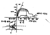
제1도는 군함에서의 소정의 대공방어를 도시하는 선도.1 is a diagram showing a predetermined air defense in a warship.
제2a도는 본 발명의 포가(砲架)의 발사각 범위를 도시하는 측면도.Fig. 2A is a side view showing the firing angle range of the carriage of the present invention.
제2b도는 제2a도에 도시된 포가의 발사각 범위를 평면도로서 도시하는 선도.FIG. 2B is a diagram showing in plan view the firing angle range of the carriage shown in FIG. 2A;
제3a도는 제2a도에 도시된 포가의 제1실시예 측면도.FIG. 3a is a side view of the first embodiment of the carriage shown in FIG. 2a.
제3b도는 제3a도에 도시된 포가의 정면도.FIG. 3B is a front view of the carriage shown in FIG. 3A.
제4a도는 제2a도에 도시된 포가의 제2실시예의 측면도.4a is a side view of a second embodiment of the carriage shown in FIG. 2a.
제4b도는 제4a도에 도시된 포가의 배면도.4b is a rear view of the carriage shown in FIG. 4a.
* 도면의 주요부분에 대한 부호의 설명* Explanation of symbols for main parts of the drawings
10 : 포가 12 : 덱크10: carriage 12: deck
14 : 수평링 16 : 링베어링14: horizontal ring 16: ring bearing
20 : 웨지형요소 22 : 정점축20: wedge-shaped element 22: vertex axis
25 : 링베어링 26 : 기준링25: ring bearing 26: reference ring
27 : 링베어링 28 : 트레인링27: ring bearing 28: train ring
34 : 링베어링 40 : 링크34: ring bearing 40: link
본 발명은 세개의 회전축을 갖는 포를 제공하여 포를 모든 방위방향에서 수직상방(이하, 정점방향으로 칭함) 및 수평보다 낮게 위치시킬 수 있게 하는 포가에 관한 것이다.The present invention relates to a carriage that provides a fabric having three axes of rotation so that the fabric can be positioned vertically upward (hereinafter referred to as apex direction) and lower than horizontal in all azimuth directions.
프랑스 공화국 특허 제2,376,394호에는 차량의 측방향롤(roll)을 조절하도록 세축에 장착되는 차량용 포에 관해 기재되어 있으며, 1935년 9월 17일에 허여된 미합중국 특허 제2,014,762호에는 세축을 갖는 대공포가에 관해 기재되어 있다. 그러나 이들중 어느 하나도 세축에 관한 개념을 발사충격이 포가에 가해지는 방향의 포의 축과의 공통 교점을 갖는 것으로 기재하고 있지는 않았다. 다른 포가 및 텔레스코프와 같은 다른 장치들이 또한 1961년 9월 26일에 허여된 미합중국 특허 제3,001,289호와, 1939년 10월 31일에 허여된 미합중국 특허 제2,178,291호와, 1982년 9월 27일에 허여된 미합중국 특허 제483,130호에 기재되어 있다. 또한, 각진 고정베이스에 장착되는 두축을 갖는 포가에 관해 1980년 6월에 발간된 “해상방어”란 명칭의 책자의 제5권에 기재되어 있다.French Republic Patent No. 2,376,394 describes vehicle guns mounted on a three-axes to adjust the lateral roll of the vehicle, and US Patent No. 2,014,762 issued on September 17, 1935, provides an anti-aircraft gun with three axes. Is described. None of these, however, describes the concept of three axes as having a common intersection with the axis of the gun in the direction in which the firing shock is applied to the carriage. Other devices such as carriages and telescopes are also disclosed in U.S. Patent No. 3,001,289, issued September 26, 1961, and U.S. Patent No. 2,178,291, issued October 31, 1939, and September 27, 1982. US Pat. No. 483,130, issued. It is also described in Volume 5 of a book entitled “Marine Defense” published in June 1980 concerning a carriage with two axes mounted on an angled fixed base.
본 발명의 목적은 반구보다 큰 구의 발사각 범위내에서 정점을 포함하는 모든 반경방향으로 포를 점진적으로 향하게 할수 있게 하는 포가를 제공하는 것이다.It is an object of the present invention to provide a carriage which allows the carriage to be progressively directed in all radial directions including vertices within the firing angle range of a sphere larger than the hemisphere.
본 발명의 또다른 목적은 발사충격이 포가에 가해지는 방향으로의 포축과 세축이 공통 교점을 가짐으로써 발사시 부하에 의해서 어떠한 회전축에 대해서도 토오크를 발생시키지 않게하는, 세축을 갖는 포가를 제공하는 것이다.It is still another object of the present invention to provide a carriage having three axes, in which the axis and the three axes in the direction in which the shot impact is applied to the carriage have a common intersection, so that no torque is generated for any rotational axis by the load during launch. .
본 발명의 또다른 목적은 두개의 축구동기가 지면에 지지되므로써 이 구동기들용으로 전기 슬립링을 사용할 필요성을 배제시켜주는 세축을 갖는 포가를 제공하는 것이다.It is a further object of the present invention to provide a carriage with three axes which eliminates the need for the use of an electric slip ring for these drivers as the two soccer motives are supported on the ground.
본 발명의 또다른 목적은 포의 길이 방향축이 범위축과 평행 할때 방위 이동율을 0까지 감소시킴이 없이 반구의 어느 반경방향으로도 포를 점차로 지향시킬 수 있게 하는 포가를 제공하는 것이다.It is a further object of the present invention to provide a carriage which allows the gun to be gradually directed in any radial direction of the hemisphere without reducing the azimuth movement rate to zero when the longitudinal axis of the gun is parallel to the range axis.
본 발명에 따라 수평에 대해 각지게 위치된 평면상에 위치하고 정점축에 대해 이동할 수 있게 장착된 플래트홈에 대해 상승 이동 및 방위 이동할 수 있게 포를 장착시킨 세축을 갖는 포가가 제공된다.According to the present invention there is provided a carriage having three axes mounted on a plane positioned angularly with respect to the horizontal and mounted on the platform so as to be capable of ascending movement and azimuth movement relative to a platform mounted to be movable relative to the vertex axis.
또한 본 발명에 따라, 플래트홈이 정점축에 대해 어느 방향으로나 제한없이 회전할 수 있게 해주는 포가가 제공된다.Also in accordance with the present invention, carriages are provided that allow the platform to rotate in any direction with respect to the vertex axis.
또한 본 발명에 따라, 포가의 세축 및 발사충격이 포가에 가해지는 방향으로의 포축이 모두 공통 교점을 갖게 구성된 포가가 제공된다.According to the present invention, there is also provided a carriage in which the three axes of the carriage and the carriage in the direction in which the shot impact is applied to the carriage have both common intersections.
이후로 이상의 본 발명의 목적 및 이점들 및 다른 목적 및 이점들에 대해서는 첨부된 도면을 참조해 상세히 설명하겠다.Hereinafter, the objects and advantages of the present invention and other objects and advantages will be described in detail with reference to the accompanying drawings.
제1도는 군함에서의 소정의 대공방어를 도시하는 선도로서, 대함 미사일이 정점으로부터 20°미만의 각도를 두고 목표물인 함정에 접근하는 것을 도시하고 있다. 이와같은 포탄을 처치하기 위해서는 축방향으로 좌우로 롤링하면서 방어태세를 갖춘 함정은 정점축을 따라, 즉 수직상방으로 발사할 수 있게 되어야만 한다. 함정은 배의 정점축으로부터 120°내의 구형내에서의 어느 반경방향으로도 발사할 수 있게 하여, 수평방향으로 접근하는 포탄등에 대해서도 발사할 수 있게 하는 것이 바람직하다.FIG. 1 is a diagram showing a given air defense in a warship, where the anti-ship missiles approach the target ship at an angle of less than 20 ° from the apex. In order to kill such a shell, a defensive trap must be able to fire along the vertex axis, ie vertically, while rolling left and right in the axial direction. It is desirable that the ship be able to fire in any radial direction within a sphere within 120 ° from the ship's vertex axis, so that it can also fire against a shell or the like approaching in the horizontal direction.
제3a도 및 3b도에는 본 발명의 제1실시예가 예시되어 있다. 포가(10)은 배에 고착된 수평덱크(12)에 고착되어 있다. (본문에서는 본 발명을 군함용인 것으로 설명하겠지만, 지상차량용으로도 사용할 수 있다는 것을 이해할 수 있을 것이다.) 덱크(12)에는 수평링(14)가 고착되어 링베어링(16)을 지지하며, 그 링베어링(16)에는 쐐기형 요소(20)의 하면(18)이 저어널되어 있다. 웨지형 요소(20)는 정점축(22)에 대해 어느방향으로나 제한없이 회전가능하게 되어 있다. 웨지형 요소(20)의 상면(24)는 하면(18)에 대해 30°만큼 각지게 고착되어 있다. 상면(24)는 링베어링(25)를 지지하고 있으며, 그 링베어링(25)에는 링베어링(27)을 지지하는 기준링(26)이 저어널되어 있으며, 링베어링(27)에는 트레인링(train ring)(28)이 저어널되어 잇다. 트레인링(28)은 방위축(30)에 대해 어느 방향으로나 제한없이 회전가능하게 되어 있다. 트레인링(28)에 대해 90°의 각도를 두고 위치하는 평면상에는 고정 상승링(32)가 고착되어, 트레인 링(28)과 함께 방위축에 대해 회전하게 되어 있다. 트레인링(28)은 링베어링(34)를 지지하며, 그 링베어링(34)에는 가동 상승링(36)이 저어널되어 있다. 링(36)은 75°까지의 점진각을 통해 웨지형요소(20)의 상면에 평행한 각도로부터 방위축(30)보다 15°낮은 각까지 상승축에 대해 피봇가능하게 되어있다. 선단이 수평링(14)에 고착되어 있는 암(44)의 말단에는 링크(40)의 하단이 볼-스크로킷 커플링(42)에 의해 피봇적으로 장착되어 있다. 또한 링크(40)의 상단은 볼-스크로킷 커플링(46)에 의해 트레인링(28)에 저어널된 기준링(26)에 피봇적으로 장착되어 있다. 링(26), (28)은 항상 동일평면상에 위치한다. 또 포(50)은 리코일 어댑터(recoil adapter) (52)에 의해 가동 상승링(36)에 장착된다. 포구(54) 및 리코일 어댑터(52)는 정점축 및 방위축을 포함하는 공통평면상에 위치한다. 가동 상승링(36)으로 전달되는 발사충격의 전달축은 정점축 및 방위축과 교차하게 된다. 상승축은 이 교차점에서 상기 공통평면을 통과하게 된다. 이러한 구성을 가짐으로써, 포의 발사시 부하로 인해 세회전축의 어느것에 대해서도 전혀 토오크가 발생되는 일이 없게 된다.3a and 3b illustrate a first embodiment of the present invention. The carriage 10 is fixed to the
링크(40)은 기준링(26) 한편으로는 트레인링(28)의 평면과 고정수평링(14) 사이에 고정기준점을 제공한다.The link 40 provides a fixed reference point between the reference ring 26 and on the one hand the plane of the train ring 28 and the fixed horizontal ring 14.
제2a도에는 포가의 회전 방위가 도시되어 있으며 제2b도에는 어떻게 세축이 상호작용하는가를 설명하기 위한 도해도가 도시되어 있다. 도시된 바와 같은 포가의 최대 양각은 방위축보다(15)작게 제한된다. 쐐기형 요소(20)이 정점축에 대해 회전함에따라, 이 맹점은 정점축에 대해 회전하게 된다. 이와같이 맹점이 회전가능하게 되므로써, 포는 구상에서 정점으로부터 수평보다 30°낮은, 즉 정점으로부터 120°각도를 이루는 범위까지의 모든 반경범위내에 위치할 수 있게 된다.The rotational orientation of the carriage is shown in FIG. 2a and a diagram for explaining how the three axes interact is shown in FIG. 2b. The maximum embossment of the carriage as shown is limited to 15 less than the azimuth axis. As the wedge-shaped element 20 rotates about the vertex axis, this blind spot rotates about the vertex axis. This blind spot is rotatable so that the artillery can be positioned within the radius of all spheres from the vertex to 30 ° lower than the horizontal, ie from 120 ° to 120 °.
요구되는 포의 한 지향에대해서 세축의 각각에 대해 다수의 각 지향을 하기 때문에 포가의 이동제어는 아주 다양하게 된다. 웨지형 요소용의 구동기 및 트레인링용의 구동기들이 지면에 지지되므로써 정점축 및 방위축에 대한 회전을 제공하기 위한 전기적 슬립링 회로가 필요없게 된다는 이점이 제공된다.The carriage control is very diverse because there are multiple angular orientations for each of the three axes for one orientation of the required carriage. The advantage that the drivers for the wedge-shaped elements and the drivers for the trainring are supported on the ground eliminates the need for an electrical slip ring circuit to provide rotation about the vertex and azimuth axes.
제4a도 및 4b도에는 본 발명의 제2실시예가 예시되어 있는데, 상기 실시예에 있어서는 기준링크(40) 대신에 유성 기어열을 사용하도록 되어 있다. 포가(60)은 덱크(64)에 고착된 베이스링(62)에 장착된다. 이 베이스링(64)에는 세 레이스-기어 조립체의 외측 레이스(66)이 고착되어 있다. 중간 레이스(68)은 다수의 로울러 베어링 (70)에 의해 외측 레이스에 저어널되어 있으며 환형기어(72)를 일체로 가지고 있다. 내측 레이스(74)는 다수의 로울러 베어링(76)에 의해 중간 레이스에 저어널되어 있으며 환형기어(78) 및 환형 정면기어(80)을 일체로 가지고 있다. 또한 중간 레이스 (68)에는 웨지형요소(84)의 베이스(82)가 고착되어 있다. 외측 레이스(86)은 또한 웨지형요소(84)의 상측 환형부(88)에 고착되어 있다. 내측 레이스(90)은 또한 다수의 로울러 베어링(92)에 의해 외측 레이스에 저어널되어 있으며 환형 정면기어(94)를 일체로 가지고 있다. 고정된 외측 상승링(96)이 내측 레이스(90)에 고착된 트레인링(98)의 공칭 평면상에 고착되어 있다. 가동의 내측 상승링(100)은 한쌍의 감마베어링(102)에 의해 외측링(96)에 저어널되어 있다. 링(100)은 환형기어(104)와 한쌍의 후방 필로우 블록(106), (108)과 직립된 한쌍의 전방 U형 연결기(110), (112)를 갖는다.4A and 4B illustrate a second embodiment of the present invention, in which the planetary gear train is used instead of the reference link 40. Carriage 60 is mounted to base ring 62 secured to deck 64. The base ring 64 is fixed to the outer race 66 of the three race-gear assemblies. The intermediate race 68 is journaled to the outer race by a number of roller bearings 70 and has an annular gear 72 integrally. The inner race 74 is journaled to the intermediate race by a number of
쐐기형 요소(84)를 정점축(22)에 대해 회전식은 기어(72)와 맞물리는 스퍼어기어(114)에 의해 제1구동이 제공된다. 기어(114)는 베어스링(62)를 통해 포구내에서 회전하도록 저어널되어 있는 입력구동 샤프트(116)을 갖는다.The first drive is provided by a spur gear 114 that engages the gear 72 that rotates the wedge-shaped element 84 about the vertex axis 22. The gear 114 has an input drive shaft 116 that is journaled to rotate in the muzzle through the bears ring 62.
제2구동은 스퍼어기어(118)에 의해 제공되는데, 그 스퍼어기어(118)는 기어 (78)과 맞물리며, 기어(78)은 기어(80)과 일체로 되어 있으며, 기어(80)은 웨지형요 소(84)의 베이스(82)의 하면에 고착된 펄로우블록(126)내에서 회전하도록 저어널되고 스퍼어기어(124)와 일체로 되어 있는 샤프트(122)를 갖는 스퍼어기어(120)과 맞물리게 된다. 스퍼어기어(124)는 트레인링(98)에 고착돤 정면기어(94)와 맞물리게 되어 있다. 그리하여 스퍼어기어(118)은 트레인링(98)은 방위측(30)에 대해 회전시키게한다. 기어(118)은 베이스링(62)를 통해 포구내에서 회전하도록 저어널되어 있는 입력구동 샤프트(128)를 갖는다.The second drive is provided by a spur gear 118, which is in mesh with the gear 78, the gear 78 being integral with the gear 80, and the gear 80 being A spur gear having a shaft 122 that is journaled to rotate in a fellow block 126 secured to the bottom surface of the base 82 of the wedge-shaped element 84 and is integral with the spur gear 124. 120). The spur gear 124 is engaged with the front gear 94 fixed to the train ring 98. Thus, the spur gear 118 causes the train ring 98 to rotate about the
제3구동은 가동의 내측 상승링을 상승축에대해 회전시키는 기어(104)와 맞물리는 스퍼어기어(130)에 의해 제공된다. 기어(130)은 고정된 상승링(96)에 고착되는 하우징(131)에 위치된 기어박스 및 전기모터에의해 구동된다. 이 모터는 적합한 전기제어회로에 접속되며, 그 전기회로에 의해 쐐기형 요소(84)에 대한 고정 상승링(96)의 이동 및 베이스링(62)에 대한 쐐기형 요소의 이동을 조절할 것이다. 이것은 도시되지 않은 스립링에 의해 통상의 방식으로 제공될 수 있다.The third drive is provided by a spur gear 130 which meshes with the gear 104 which rotates the inner rising ring of the move about the lift shaft. The gear 130 is driven by a gearbox and an electric motor located in the housing 131 which is fixed to a fixed lift ring 96. This motor is connected to a suitable electrical control circuit, which will regulate the movement of the fixed lifting ring 96 relative to the wedge-shaped element 84 and the movement of the wedge-shaped element relative to the base ring 62. This may be provided in a conventional manner by slipping, not shown.
본 발명의 특징은 샤프트(116), (128)에 결합되는 전기 모터인 다른 두개의 구동기(116M) (128M)이 지면에 대해 고정되어 있기때문에 고정 와이어를 사용하여 전기 제어회로에 접속될 수도 있다는데 있다.A feature of the invention is that two other drivers 116M, 128M, which are electric motors coupled to shafts 116, 128, may be connected to the electrical control circuit using a fixing wire because they are fixed relative to the ground. have.
본문에서는 화이브 배럴 개트링(five barrel gatling)형 포와 같은 적합한 포 (132)가 가동의 내측 상승링에 고착되어 있다. 포의 하우징은 각각 스핀들(138) (140)을 갖는 한쌍의 리코일 어댑터(134) (136)을 포함하며, 스핀들(138) (140)은 각각 U형 연결기 및 블록(106)사이와 U형 연결(112) 및 블록(108) 사이에 장착된다. 포신(132)들이 회전함에따라 가가 포신들은 장전, 발사, 탄피 제거등의 순서로 사격이 이루어진다. 탄환은 포신의 길이 방향축이 리코일 어댑터의 스핀들의 길이방향과 동일평면상에 있을때 발사되게 된다.In the text, a suitable fabric 132, such as a five barrel gatling type fabric, is secured to the movable inner lifting ring. The housing of the fabric comprises a pair of recoil adapters 134 and 136 with spindles 138 and 140 respectively, the spindles 138 and 140 respectively being connected between a U-shaped connector and a block 106 and a U-shaped connection. It is mounted between 112 and block 108. As the barrels 132 rotate, the Gaga barrels are fired in the order of loading, firing, shell removal, and the like. The bullet is to be fired when the longitudinal axis of the barrel is coplanar with the longitudinal direction of the spindle of the recoil adapter.
대체로 정점축(22)와 동축적으로 위치된 슈우트(146)으로부터 포의 스트리 퍼-휘더(stripper feeder) (144)로 벨트에 링크 연결된 탄환이 포에 제공될 수 있을 것이다. 슈우트는 정점축과 동축적으로 위치된 탄환정렬기구(148)에 결합될 것이다. 이 기구는 링크 연결된 탄환을 고정공급원으로 부터 정점축에 대해, 두축을 갖는 포가의 경우에는 방위축에 대해 포가의 회전을 제한 시킴이 없이 이송시켜준다.Bullets linked to the belt may be provided to the gun from the chute 146 coaxially positioned with the apex shaft 22 to the stripper feeder 144 of the gun. The chute will be coupled to a bullet alignment mechanism 148 located coaxially with the vertex axis. This mechanism transports linked bullets from a fixed source about the axle axis, in the case of carriages with two axes, without restricting the rotation of the carriage about the azimuth axis.
포가에는 가동의 내측 상승링(100)에 고착되어 그로부터 연장되는 브래킷 (152)에 고정된 것으로 도시되어 있는 목표를 포획 레이더(150)과 같은 발사제어기구가 제공될 수 있을 것이다.The carriage may be provided with a launch control mechanism, such as the capture radar 150, aimed at being fixed to a bracket 152 that is secured to and extends from the inner rising
Claims (7)
Applications Claiming Priority (3)
| Application Number | Priority Date | Filing Date | Title |
|---|---|---|---|
| US293.716 | 1981-08-17 | ||
| US06/293,716 US4437384A (en) | 1981-08-17 | 1981-08-17 | Gun mount |
| US293716 | 1989-01-05 |
Publications (2)
| Publication Number | Publication Date |
|---|---|
| KR840001329A KR840001329A (en) | 1984-04-30 |
| KR890000774B1 true KR890000774B1 (en) | 1989-04-06 |
Family
ID=23130256
Family Applications (1)
| Application Number | Title | Priority Date | Filing Date |
|---|---|---|---|
| KR8203693A KR890000774B1 (en) | 1981-08-17 | 1982-08-17 | Gun mount |
Country Status (9)
| Country | Link |
|---|---|
| US (1) | US4437384A (en) |
| EP (1) | EP0072669B1 (en) |
| JP (1) | JPS5875697A (en) |
| KR (1) | KR890000774B1 (en) |
| CA (1) | CA1181276A (en) |
| DE (1) | DE3275232D1 (en) |
| ES (1) | ES8309000A1 (en) |
| IL (1) | IL66466A (en) |
| NO (1) | NO155263C (en) |
Families Citing this family (15)
| Publication number | Priority date | Publication date | Assignee | Title |
|---|---|---|---|---|
| IT8353861V0 (en) * | 1983-10-26 | 1983-10-26 | Agusta Aeronaut Costr | BRANDABLE WEAPON FOR AIRCRAFTS IN PARTICULAR HELICOPTERS |
| US4662263A (en) * | 1984-12-05 | 1987-05-05 | General Electric Company | Ammunition feed system interface |
| US4635529A (en) * | 1984-12-21 | 1987-01-13 | General Electric Company | Seal assembly |
| EP0405177A1 (en) * | 1989-06-30 | 1991-01-02 | Werkzeugmaschinenfabrik Oerlikon-Bührle AG | Device for feeding with cartridges a gun which is moveable in elevation |
| FR2662788B1 (en) * | 1990-05-31 | 1994-08-12 | France Etat Armement | MOUNTING OF TURRET AND ITS REMOTE OBSERVATION SYSTEM, WITHOUT DEAD ANGLE. |
| GB2248599A (en) * | 1990-10-10 | 1992-04-15 | Sous Chef Ltd | Filling and sealing sterilised containers |
| GR980100049A (en) * | 1997-02-19 | 1998-10-30 | Buck Werke Gbmh & Co | Arrangement for multiple launches of missiles from the shoulder |
| AUPP243598A0 (en) | 1998-03-18 | 1998-04-09 | Rapak Asia Pacific Limited | Improvements relating to tote bins |
| CH693687A5 (en) * | 1999-06-10 | 2003-12-15 | Contraves Ag | Mount, launcher with a launching tube assembly and a carriage, ammunition containers for carriage with launching tube assembly and use of the launcher. |
| FR2852385B1 (en) * | 2003-03-13 | 2005-06-03 | Giat Ind Sa | MULTITUBE TURRET FOR HIGH ENERGY MUNITION |
| DE102004060241A1 (en) | 2004-12-15 | 2006-06-22 | Blohm + Voss Gmbh | Ship with foundations for equipment elements |
| ITMI20060668A1 (en) * | 2006-04-05 | 2007-10-06 | Oto Melara Spa | AUXILIARY STORAGE DEVICE |
| KR101237602B1 (en) | 2010-05-19 | 2013-02-26 | 정인 | automatic correction apparatus for trajectory of a projectile and correction method using the same |
| KR101508625B1 (en) * | 2013-11-14 | 2015-04-08 | 삼성중공업 주식회사 | Apparatus and method for assembling bearing |
| KR101516163B1 (en) * | 2013-11-15 | 2015-05-04 | 삼성중공업 주식회사 | Assembling method shaft structure of wind turbine |
Family Cites Families (2)
| Publication number | Priority date | Publication date | Assignee | Title |
|---|---|---|---|---|
| US2712271A (en) * | 1949-05-07 | 1955-07-05 | Richard E Wabnitz | Adjustable support apparatus |
| FR2376394A1 (en) * | 1977-01-04 | 1978-07-28 | Thomson Brandt | Gun turret for vehicle or ship - has three main swivelling axes to allow for vehicle or ship side tilt or roll |
-
1981
- 1981-08-17 US US06/293,716 patent/US4437384A/en not_active Expired - Lifetime
-
1982
- 1982-02-26 CA CA000397264A patent/CA1181276A/en not_active Expired
- 1982-08-04 IL IL66466A patent/IL66466A/en unknown
- 1982-08-11 DE DE8282304251T patent/DE3275232D1/en not_active Expired
- 1982-08-11 EP EP82304251A patent/EP0072669B1/en not_active Expired
- 1982-08-16 NO NO822782A patent/NO155263C/en unknown
- 1982-08-17 JP JP57141773A patent/JPS5875697A/en active Granted
- 1982-08-17 ES ES515077A patent/ES8309000A1/en not_active Expired
- 1982-08-17 KR KR8203693A patent/KR890000774B1/en active
Also Published As
| Publication number | Publication date |
|---|---|
| JPH0417357B2 (en) | 1992-03-25 |
| CA1181276A (en) | 1985-01-22 |
| ES515077A0 (en) | 1983-10-01 |
| ES8309000A1 (en) | 1983-10-01 |
| NO155263B (en) | 1986-11-24 |
| NO822782L (en) | 1983-02-18 |
| DE3275232D1 (en) | 1987-02-26 |
| EP0072669A2 (en) | 1983-02-23 |
| KR840001329A (en) | 1984-04-30 |
| EP0072669B1 (en) | 1987-01-21 |
| EP0072669A3 (en) | 1983-05-04 |
| IL66466A (en) | 1987-02-27 |
| US4437384A (en) | 1984-03-20 |
| JPS5875697A (en) | 1983-05-07 |
| NO155263C (en) | 1987-03-04 |
Similar Documents
| Publication | Publication Date | Title |
|---|---|---|
| KR890000774B1 (en) | Gun mount | |
| US9032859B2 (en) | Harmonized turret with multiple gimbaled sub-systems | |
| US7669513B2 (en) | Multiple weapon system for armored vehicle | |
| US7487705B2 (en) | Weapon sight | |
| US20010015126A1 (en) | Multiple-barrel mortar assembly for launching grenades off the side of a combat vehicle | |
| US10371479B2 (en) | Stabilized integrated commander's weapon station for combat armored vehicle | |
| US7798050B2 (en) | Quick-response drive mechanism for controlling the movement of an object relative to a support | |
| US3715953A (en) | Aerial surveillance and fire-control system | |
| US7086318B1 (en) | Anti-tank guided missile weapon | |
| CN112693532A (en) | Crawler-type multifunctional ground unmanned combat platform | |
| SE407621B (en) | KORBART WEAPON | |
| JP2002527712A (en) | Self-propelled cannon | |
| KR102605255B1 (en) | Grenade launch repulsion control device for drones | |
| EP1671075B1 (en) | Multiple weapon system for an armored vehicle | |
| CN215944714U (en) | Crawler-type multifunctional ground unmanned combat platform | |
| US5078044A (en) | Turret comprising a rotating joint and an angular velocity reduction device | |
| US3820436A (en) | Gun turret especially for armored vehicles | |
| US4346644A (en) | Foldout cradle apparatus for mounting an automatic cannon to a turret exterior | |
| DE1800330A1 (en) | Armored vehicle with anti-aircraft armament | |
| RU2217679C1 (en) | Fighting vehicle of salvo-fire jet-driven system on chassis of base tank | |
| CN109470083B (en) | Universal tube-turning machine gun weapon station | |
| US20220412683A1 (en) | Ammunition launching device | |
| US3140685A (en) | Propeller stabilized and controlled torpedoes | |
| CN113945121A (en) | Self-propelled rocket gun with double launching devices | |
| RU2067279C1 (en) | Method of weapon laying on moving air targets |