KR890000692B1 - Method of testing and verifying a performance for insulation to ground of a disconnecting switch when breaking a charging current - Google Patents
Method of testing and verifying a performance for insulation to ground of a disconnecting switch when breaking a charging current Download PDFInfo
- Publication number
- KR890000692B1 KR890000692B1 KR1019830003846A KR830003846A KR890000692B1 KR 890000692 B1 KR890000692 B1 KR 890000692B1 KR 1019830003846 A KR1019830003846 A KR 1019830003846A KR 830003846 A KR830003846 A KR 830003846A KR 890000692 B1 KR890000692 B1 KR 890000692B1
- Authority
- KR
- South Korea
- Prior art keywords
- voltage
- disconnector
- power supply
- electrode
- electrodes
- Prior art date
Links
Images


Classifications
-
- G—PHYSICS
- G01—MEASURING; TESTING
- G01R—MEASURING ELECTRIC VARIABLES; MEASURING MAGNETIC VARIABLES
- G01R3/00—Apparatus or processes specially adapted for the manufacture or maintenance of measuring instruments, e.g. of probe tips
-
- H—ELECTRICITY
- H01—ELECTRIC ELEMENTS
- H01H—ELECTRIC SWITCHES; RELAYS; SELECTORS; EMERGENCY PROTECTIVE DEVICES
- H01H33/00—High-tension or heavy-current switches with arc-extinguishing or arc-preventing means
- H01H33/02—Details
- H01H33/26—Means for detecting the presence of an arc or other discharge
-
- G—PHYSICS
- G01—MEASURING; TESTING
- G01R—MEASURING ELECTRIC VARIABLES; MEASURING MAGNETIC VARIABLES
- G01R31/00—Arrangements for testing electric properties; Arrangements for locating electric faults; Arrangements for electrical testing characterised by what is being tested not provided for elsewhere
- G01R31/327—Testing of circuit interrupters, switches or circuit-breakers
- G01R31/333—Testing of the switching capacity of high-voltage circuit-breakers ; Testing of breaking capacity or related variables, e.g. post arc current or transient recovery voltage
- G01R31/3333—Apparatus, systems or circuits therefor
Abstract
Description
제1도는 대지절연에 대한 종래 검증시험법의 한 예를 나타내는 회로도.1 is a circuit diagram showing an example of a conventional verification test method for earth insulation.
제2도는 제1도에 있어서의 전압 파형도.FIG. 2 is a voltage waveform diagram in FIG.
제3도는 대지절연에 대한 종래 검증시험법을 수행하기 위하여 가스절연 단로기의 다른 예를 나타내는 회로도.3 is a circuit diagram showing another example of a gas insulated disconnector to perform a conventional verification test method for earth insulation.
제4도는 본 발명에 의한 대지절연 검증시험법을 수행하기 위하여 가스절연 단로기의 전형적 실시태양을 나타내는 회로도.4 is a circuit diagram showing an exemplary embodiment of a gas insulated disconnector for performing the earth insulation verification test method according to the present invention.
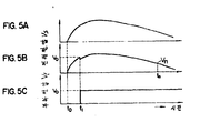
제5a도~제5c도는 제4도의 전압 파형도.5a to 5c are voltage waveform diagrams of FIG.
제6도는 제4도의 가동 전극의 구동기구를 나타내는 횡단면도.6 is a cross sectional view showing a drive mechanism of the movable electrode of FIG.
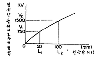
제7도는 단로기의 전극간 거리와 플래시오우버 전압 사이의 관계를 나타내는 도.7 shows the relationship between the distance between electrodes of a disconnector and the flashover voltage.
제8도는 본 발명에 의한 대지절연 시험원리를 나타내는 전압 파형도.8 is a voltage waveform diagram showing a ground insulation test principle according to the present invention.
제9도는 본 발명의 다른 예를 나타내는 단로기의 횡단면도.9 is a cross-sectional view of a disconnector showing another example of the present invention.
제10도는 제9도의 시험원리를 나타내는 특성도.10 is a characteristic diagram showing the test principle of FIG.
제11a도 및 제11b도는 제9도의 각 부분에 있어서의 전압파형도.11A and 11B are voltage waveform diagrams in respective parts of FIG.
제12도는 본 발명의 또 다른 예를 나타내는 단로기의 횡단면도.12 is a cross-sectional view of a disconnector showing still another example of the present invention.
본 발명은 충전전류의 차단시, 탱크형의 가스절연 단로기의 대지절연 검증시험법에 관한 것이다.The present invention relates to the earth insulation verification test method of the tank type gas insulated disconnector when the charging current is interrupted.
이 가스절연 단로기의 충전전류의 단로시험은 일반적으로 현지 가스절연 단로기와 대략 등가회로에 의하여 수행된다.The disconnection test of the charging current of this gas insulated disconnector is generally carried out by the local gas insulated disconnector and approximately equivalent circuit.
제1도는 등가횡로의 한 예를 나타낸다. AC전원(2)은 모선(4)을 통하여 단로기 (6)의 한쪽 단자에 접속되며, 차단기(10)는 모선(8)을 통하여 다른 단자에 연결되어 있다. 전력 공급장치(도시되지 않음)는 모선(12)을 통하여 상기 차단기(10)의 타단에 접속되며, 이리하여 회로를 구성한다. 단로기(6)의 부하측에는 정전용량(CI)이 모선(8)과 접지 사이에 부가된다. 단로기(6)와 차단기(10)가 닫혔을 때 전류는 단로기(6)를 통하여 전원(2)에서 차단기(10)로 흐르며, 용량(CI)은 충전된다.1 shows an example of an equivalent transverse line. The AC power supply 2 is connected to one terminal of the disconnector 6 via the bus 4, and the breaker 10 is connected to the other terminal through the
차단기(10)가 열릴 때, 회로는 모선(8)의 정전용량(CI)만이 단로기(6)의 부하측에 가해지도록 구성된다. 단로기(6)가 이러한 상태로 열릴 때 상기 부하용량(CI)의 충전전류 차단으로 된다.When the breaker 10 is opened, the circuit is configured such that only the capacitance CI of the
제2도는 단로기(6)를 개극함으로써 용량(CI)의 충전전류 차단시 전원측의 전압 Vs과 단로기(6)의 부하측의 저압V1의 추이를 나타낸다. 제2도에 있어서 파선은 상기 전원측의 전압 Vs을 그리고 실선은 부하측의 전압 V1을 나타낸다.2 shows the transition of the voltage Vs on the power supply side and the low voltage V1 on the load side of the disconnector 6 when the charge current of the capacitor CI is interrupted by opening the disconnector 6. In FIG. 2, the broken line shows the voltage Vs on the power supply side and the solid line shows the voltage V1 on the load side.
단로기(6)가 시간 ts에서 개극하고 전극간의 거리는 시간의 경과에 따라 증가한다. 예컨대, 전압 Vs이 0 V이라면, 단로기(6)는 개극하고, 용량 CI의 전압은 또 0V이다. 전압이 시간 t1에서 V1(전극간 거리는 l1)일 때, 단로기(6)의 전극간 전위차는 V1로 하고, 따라서 방전(재발호)은 전극에서 발생한다. 이리하여 부하용량 CI은 충전되고, 부하전압은 V1로 된다. 곧 전극간 길이는 l2(l2>l1), 그리고 전압이 시간 t2에서 V2로 될 때 단로기의 전극간 사이의 전위차는 V2-V1로 된다(여기서 V2-V1)>V1)이다. 이라하여 재발호가 발생하고, 부하용량은 충전되며, 부하전압은 V2로 된다.The disconnector 6 opens at time ts and the distance between the electrodes increases with time. For example, if the voltage Vs is 0V, the disconnector 6 is opened and the voltage of the capacitor CI is 0V again. When the voltage V 1 at time t 1 in the (inter-electrode distance l 1), the potential difference between electrodes of the disconnecting switch 6 to V 1, and thus discharge (recurrent arc) occurs at the electrode. Thus, the load capacitance CI is charged, and the load voltage becomes V 1 . In other words, the interelectrode length is l 2 (l 2 > l 1 ), and when the voltage becomes V 2 at time t 2 , the potential difference between the electrodes of the disconnector becomes V 2 -V 1 (where V 2 -V 1 ) > V 1 ). Thus, re-calling occurs, the load capacity is charged, and the load voltage is V 2 .
이리하여 전극간장이 시간의 경과에 따라 증가할 때, 상기 전극의 재발호를 일으키는데 필요한 전극간 전위차는 증가하며, 그러므로 재발호의 시간은 제2도와 같이 점차적으로 길어진다.Thus, when the electrode liver increases with time, the potential difference between electrodes necessary for causing the electrode to be re-issued increases, and therefore the time of re-homing is gradually longer as shown in FIG.
상기와 같은 방법으로 재발호의 반복 결과로서 방전을 위하여 필요한 전극간 전압은 전원 2PU(단, 1PU는 전원전압 Vs의 첨두치를 나타낸다)의 첨두시 사이의 전압으로 될 때, 최종 재발호가 발생하며, 차단은 제2도와 같이, 시간 t11에서 완료된다. 이리하여 부하측 전압 V1은 정치(여기서는 1PU)로 유지된다.In the above manner, when the inter-electrode voltage required for discharge as a result of repetition of re-calling becomes the voltage between peaks of power supply 2PU (where 1PU indicates peak value of power supply voltage Vs), the final re-call occurs. Is completed at time t 11 , as shown in FIG. 2. Thus, the load side voltage V1 is held at a fixed state (here 1PU).
재발호와 동시에 서어지전압(16)은 제2도와 같이 발생한다. 특히 동도에 있어서와 같이 재발호가 AC 전압의 첨두치(2PU) 사이에서 행하여질 때 2.5PU(예컨대, n=2.5, 제2도)와 동등한 서어지전압이 발생한다. 그러므로 단로기는 상기와 같은 상황하에서도 대지절연을 만족시켜야 한다. 따라서 상기 단로기에 대한 시험은 소정간장, 전극간 전압 및 서어지전압에 대한 대지절연의 특성을 조사하기 위하여 행해진다. 그러나 이 시험에서 개극시, 전원전압의 위상이 정수로 세트된다 할지라도, 단로기의 최종 재발호가 행해질 때, 상기 전원전압의 위상은 모든 시험에 있어서 다르며, 따라서 발생되는 서어지전압은 정수로 되지 않는다. 환언하면, 최종 재발호는 전원전압의 피이크에서 반드시 행하여지는 것은 아니다. 그러므로 실제 단로기에 대하여 발생되는 조건을 만족시킬 수 있는 시험을 치르기 위하여 많은 시험을 실시할 필요가 있다. 이로 인하여 많은 비용을 들게 하는 폐단이 있는 것이다.At the same time as the recall, the
상기 폐단을 해소하기 위하여 모의 시험법이 제안되었으며, 제3도와 같은 회로가 구성되어 이리하여 제2도의 시간 t10및 t12사이의 상태만을 모의할 수가 있다.A simulation test method has been proposed to solve the above-described closure, and a circuit as shown in FIG. 3 is constructed so that only a state between the times t 10 and t 12 of FIG. 2 can be simulated.
이 방법은 S. Nishiwaki, Y. Kanno, S. Satoh, E. Haginomori, S. Yamashita, S. Yanabu의 제16도에 기재되어 있다. 즉, “ground Fault by Restriking Surge of SF6 Gas-Insulated Disconnecting Switch and its Synthetic Tests,” IEEE PES, Paper 82 WM 187-3, 1982에 개시되어 있다.This method is described in Figure 16 of S. Nishiwaki, Y. Kanno, S. Satoh, E. Haginomori, S. Yamashita, S. Yanabu. That is, “ground Fault by Restriking Surge of SF6 Gas-Insulated Disconnecting Switch and its Synthetic Tests,” IEEE PES, Paper 82 WM 187-3, 1982.
이 방법에 의하면, 부싱(24), (26)은 단로기(6)의 양단에 배치되며, 상기 단로기(6)의 일단에 은 상기 부싱(24)을 통하여 전원(20)과 용량(22)에 접속되고, 타단은 부싱(26)을 통하여 다른 전원(36) 및 용량(34)에 접속되고, 이리하여 상기와 같은 회로를 사용하여 시험을 행한다. 제3도에는 전원(36)은 부하측 전원 V1을 모의하기 위하여 DC 전압발생기기 나타나 있으며, 전원(20)은 전원(36)의 극성에 반대되는 극성을 가진 전원전압 Vs을 모의하기 위한 임펄스 전압발생기 또는 반파 AC 전압발생기이다. 참조번호(28) 및 (30)은 전원전압 Vs과 부하전압 V1을 각각 검지하고 분할하고, 명령추출을 하기 위하여 전압 분할기를 가리킨다. 전압 분할기(28), (30)의 출력은 표시장치, 예컨대 오실로스코우프(32)에 가해지며, 이리하여 전원전압 Vs과 부하전압 V1의 파형을 가리킨다.According to this method, the bushings 24, 26 are arranged at both ends of the disconnector 6, and at one end of the disconnector 6 is connected to the power source 20 and the capacitor 22 via the bushing 24. The other end is connected to the other power source 36 and the
이 시험에서 단로기의 전극간장은 처음에 충전전류의 차단시, 최대 호장과 동등한 길이로 세트된다. 그리고, 전원(20)의 AC 출력의 첨두치에 대응한 DC 전압은 전원(36)에서 단로기의 한접점에 가해진다. 그런 후에 전원(36)의 DC 전압의 극성에 역인 극성을 가진 AC 전압의 1/4 사이클의 파형에 대응하는 드레스호울드 전압은 전원(20)에서 단로기의 다른 접점에 가해진다. 이리하여 제2도의 시간 t10과 t12사이에 상태는 재발호를 행하기 위하여 제3도의 단로기에서 모의된다.In this test, the electrode liver of the disconnector is initially set to the same length as the maximum length of the circuit when the charging current is interrupted. The DC voltage corresponding to the peak value of the AC output of the power supply 20 is applied to the contact point of the disconnector in the power supply 36. Thereafter, a dresshold voltage corresponding to a waveform of a quarter cycle of an AC voltage having a polarity inverse to that of the DC voltage of the power supply 36 is applied to the other contact of the disconnector in the power supply 20. Thus, between the times t 10 and t 12 of FIG. 2, the state is simulated in the disconnector of FIG. 3 to perform a recall.
상기와 같이 단로기에서 대한 가장 심한 재점호상태는 모의되며, 이 때에 발생될 서어지전압에 있어서의 대지 절연은 검증된다. 이 방법에 의하면, 가장 심한 상태만을 선택하여 충분히 검증을 수행할 수가 있다. 그러나 대규모의 전체 시험시설이 두 고전압전원이 필요하고 또 고전압에 대한 두부싱이 필요하다는 결점이 있다. 특히, 최근 개발이 진행되고 있는 UHV용의 경우에는 보다 더 큰 규모로 되어, 시험 비용은 막대하게 든다.As described above, the most severe re-ignition state in the disconnector is simulated, and the earth insulation at the surge voltage generated at this time is verified. According to this method, only the most severe state can be selected and sufficient verification can be performed. However, there is a drawback that large, large test facilities require two high voltage sources and two high voltage bushings. In particular, for UHV, which is being developed recently, the scale is larger, and test costs are enormous.
따라서 본 발명의 목적은 소규모의 설비에 의하여 단로기 충전전류 차단시의 대지절연 검증을 가능하게 하는 방법을 제공하는데 있다.Accordingly, an object of the present invention is to provide a method for enabling earth insulation verification at the time of disconnecting the charge current of the disconnector by a small-scale facility.
본 발명자는 가스절연 모선의 방전시정수가 충분히 크다는 것을 실험에 의하여 확인하고, 극간 방전에 의하여 가스절연 모선을 충전시킴으로써 가스모선의 충전전압이 장시간 충분히 잔류시킬 수 있는 것을 확인하였다. 따라서 종래 방법으로 DC 전압발생기를 사용한 단로기의 한 접점에 DC 전압을 인가하는 대신에 단로기의 극간 방전으로 인하여 가스절연 모선을 충전시키는 것이 바람직하다는 것을 알게 되었다. 그러므로 전원과 부싱은 상기 단로기의 한쪽에만 설치해도 무방하게 되었다.The present inventors confirmed by experiment that the discharge time constant of the gas insulated busbar was sufficiently large, and confirmed that the charging voltage of the gas busbar could sufficiently remain for a long time by charging the gas insulated busbar by inter-discharge. Therefore, it has been found that it is preferable to charge the gas insulated bus bar due to the inter-pole discharge of the breaker instead of applying a DC voltage to a contact point of the breaker using the DC voltage generator in the conventional method. Therefore, the power supply and the bushing may be installed only on one side of the disconnector.
제4도에는 본 발명에 의한 대지절연 시험을 수행하기 위하여 가스절연 단로기의 전형적 실시예의 회로도가 표시되어 있다. 제4도에 있어서, 제1도 및 제3도의 기능과 같은 기능을 가진 부품과 엘레멘트는 동일 참조번호로 지정하여 표시하였다.4 is a circuit diagram of an exemplary embodiment of a gas insulated disconnector for performing the earth insulation test according to the present invention. In FIG. 4, parts and elements having the same functions as those of FIGS. 1 and 3 are designated by the same reference numerals.
접지 탱크내에 수납된 단로기(6)의 고정전극(64)은 부하를 형성하는 가스모선 (54)의 중심도체(56)에 접속되어 있다. 정전용량 CI은 가스모선(54)의 중심도체(56)와 고전압도체(58)의 사이에 형성된다. 중심도체(56)는 절연 스페이서(52)에 의하여 절연 및 지지된다. 단로기(6)의 가동전극(62)은 중심도체(55)에 접속되어 있다. 중심도체(55)는 부싱(24) 및 리이드선(50)을 통하여 전원(40)에 접속되어 있다. 중심도체 (55)는 절연지지물(53)에 의하여 지지되어 있다.The fixed
단로기(6)의 전원측 전압 Vs과 부하측 전압 Vl은 분압기(28), (30)에 의하여 검지 및 분할되고, 파형 표시장치, 예컨대 오실로스코우프(32)에 가해진다.The power supply side voltage Vs and the load side voltage Vl of the disconnector 6 are detected and divided by the
전원(40)은 공지전원으로 이는 등가정전용량 Cs을 가진 전원 본체(42)와 AC전원(44)의 출력전압을 규제하기 위한 전압 조정기(45)와 상기 전압조정기(45)의 출력을 정류하기 위한 정류기(46)와 상기 정류기(46)의 출력 전압극성을 선택적으로 절체시키기 위한 극성절체 스위치(47)와 시동기(48)로 구성되어 있다. 정류기의 출력은 상기 전원본체의 용량 Cs에 축적된다. 트리거 신호가 상기 시동기(48)에서 가해질 때 상기 용량 Cs에 축적된 전하는 방전되고, 따라서 제5도의 펄스와 같은 고전압은 부싱 (24)을 통하여 단로기(6)의 가동전극에 가해진다. 전원(40)의 출력전압은 전압 조정기 (45)에 의하여 조정될 수 있다.The power source 40 is a well-known power source, which rectifies the output of the voltage regulator 45 and the voltage regulator 45 for regulating the output voltage of the power
현지 전력공급장치의 성공적 모의를 위하여 용량 Cs치는 부하측 가스모선의 전극간 용량 CI과 전원측 등 가정전용량 Cs 사이의 관계에 관련하여 용량 CI치 보다 최소한 1디지트 큰 치로 세트된다.For the successful simulation of the local power supply, the capacity Cs value is set at least one digit larger than the capacity CI value in relation to the relationship between the capacitance CI between the electrodes of the load side gas bus and the home capacitance Cs such as the power supply side.
가동전극(62)은 제6도에 도시된 구동장치(66)에 의하여 수동 가동될 수 있다. 제6도의 것과 같은 구동장치는 예컨대 제2도에 표시되어 있으며, 미국 특허 제4, 263, 491호에 개시되어 있다.The movable electrode 62 can be manually operated by the driving
제6도는 단로기(6)와 제4도의 구동장치를 나타내는 상세 횡단면도이다. 이 단로기(6)는 접지탱크의 고전압도체(58)에 배치된 가동전극(62)과 고정전극(64)이 포함되어 있으며, 이들 주위에는 전계완화용의 시일드(68), (70)가 부착되어 있다. 가동전극(62)은 중심도체(55)의 단부에 고정된 도전원통부재(72)내측에 접동자재로 지지되어 있다. 중심도체(55)는 절연지지물(53)에 의하여 지지되어 있다.FIG. 6 is a detailed cross sectional view showing the disconnector 6 and the driving device of FIG. The disconnector 6 includes a movable electrode 62 and a fixed
가동전극(62)를 접동시키기 위한 구동장치에 대하여 설명하면 아래와 같다. 가동전극의 단부는 절연 작동봉(74)을 통하여 링크부재(76)의 일단과 게지된다. 이 링크부재(76)는 지점(78) 주위를 회동 가능하며, 이 링크부재(78)의 타단은 상기 작동붕 (80)의 일단과 계합되어 있다. 작동봉(80)의 타단은 L자형으로 되어 있고, 암나사 부분(82)이 내측에 형성되어 있다. 니이들(90)은 상기 봉(80)의 단연부에 부착되어 있다. 암나사(82)의 일단은 고전압도체(58)의 회동자재로 지지되어 있으며, 타단은 핸들(86)에 연결된 숫나사 봉(84)에 나합되게 이루어져 있다. 스케일봉(88)은 가동전극(62)과 고정전극(64) 사이의 거리 L를 위하여 규칙적 구간으로 구분되어 있다. 이 눈금은 각동봉(80)의 이동과 가동 및 고정전극간의 거리 L에 관련하여 니이들(90)의 이동량 L' 사이의 관계를 사전에 획득함으로써 결정된다.A driving device for sliding the movable electrode 62 will be described below. An end of the movable electrode is connected with one end of the link member 76 through the insulated operating rod 74. The link member 76 is rotatable around the point 78, and the other end of the link member 78 is engaged with one end of the working
이러한 구성으로, 핸들(86)을 시계방향으로 회전시킴과 동시에 예컨대 작동봉 (80)은 화살표(92)와 같은 방향으로 움직인다. 이리하여 작동봉(74)에 따라서 가동전극(62)은 화살표 방향(94)으로 움직인다. 이대, 전극간의 거리 L는 상기 니이들(90)에 의하여 지시된 치이다.In this configuration, the operating
이리하여 전극간 거리 L는 핸들(86)의 조작에 의하여 어떤 치로도 세트시킬 수가 있다. 단로기가 시판될 경우, 구동장치(66) 이외에 모우터 또는 공기 압력을 사용하여 전극간 거리를 원격조정 가능한 장치를 제공할 수가 있는 것이다.In this way, the distance L between electrodes can be set to any value by the operation of the
제4도 및 제6도에 도시된 단로기를 사용하여 대지절연 검증시험을 실시하는 방법을 기술하면 다음과 같다.The method of performing the earth insulation verification test using the disconnectors shown in FIGS. 4 and 6 is as follows.
첫째, 단로기(6)의 전극간 거리 L는 구동장치(66)에 의하여 일정치로 세트된다. 그리고 제5도에 표시한 펄스 유사전압은 시간 t0에서 전원(40)으로부터 단로기(6)로 가해진다. 전원전압이 시간 t1에서 전극간 거리 L에 의하여 결정되는 소정치에 도달할 때, 방전은 전극에 발생하며, 따라서 전하는 부하측의 가스모선에 축적된다. 이리하여 전원측 전압 Vs과 부하측 전압 V1은 제5b도 및 제5c도와 같이 파형을 나타낸다. 즉, 방전은 시간 t1에서 전극에서 행해지며, 제5c도의 DC 전압 V1은 부하측 모선(56)에 잔류된다. 이 잔류전압(즉, 잔류충전 전압)의 방전시 정수는 부하측 모선(56)의 정전용량 CI과 고전압 도체(58) 등을 절연 지지하는 절연지지물(52)의 절연 저항에 의하여 결정된다. 상기 방전시정수는 수시간 내지 수일간의 오오더이다. 왜냐하면, 일반적으로 가스절연장치에 사용되는 상기 지지물의 절연저항은 대기중에서 사용되는 지지물의 절연저항보다 훨씬 높기 때문이다. 즉, 가스절연장치의 절연지지물의 용량은 크고 이에 대하여 인덕턴스 및 저항성분은 작기 때문에 잔류전압은 감소되지 않고 보지될 수가 있다. 그러므로 대지절연 시험이 상기 잔류충전이 부하측 모선(56)으로 형성된 후, 수십분 이내에서 시험을 실시하는 한 부하측 모선의 잔류전압은 감소되지 않고 방전시의 전압은 그대로 보지된다. 그러므로 부하 잔류전압의 감소를 고려할 필요가 있다.First, the inter-electrode distance L of the disconnector 6 is set at a constant value by the
상기 방법에 의하여 단로기의 전극간 거리 및 인가전압을 적당히 변화시킴으로써 부하측에 임의의 DC전압을 잔류할 수 있게 되기 때문에 종래 방법처럼 부하측에 DC전원을 별도로 설치할 필요가 없다.By appropriately changing the distance between the electrodes and the applied voltage of the disconnector by the above method, any DC voltage can remain on the load side, so that there is no need to separately install a DC power supply on the load side as in the conventional method.
상기 단로기의 충전전류 차단시, 대지절연의 성능은 최대 아아크거리인 가등전극 위치에서 발생되는 제점호 서어지에 대한 성능으로 결정된다. 재점호 서어지가 가장 높게 되는 것은 상기와 같이, 정부극성의 파고 치간에서의 재점호로 된다. 그러므로 대지절연에 대한 성능 검증으로서는 단로기 전극간의 거리를 소정치로 떨어지게 하고, 전압은 상기 방법에 따라 부하측에 인가한다. 그리고서 전극간 거리는 소정치로 증가시키며, 전원측에서 역극성동 레벨의 전압을 인가함으로써 극간을 방전시켜, 그때의 대지절연을 검증하게 된다.When the charge current of the disconnector is blocked, the performance of the ground insulation is determined by the performance of the zero arc surge generated at the position of the light electrode which is the maximum arc distance. As the above-mentioned surge is the highest surge, it is the re-ignition at the height of the government polarity. Therefore, as the performance verification for the ground insulation, the distance between the disconnector electrodes is dropped to a predetermined value, and the voltage is applied to the load side according to the above method. The distance between the electrodes is then increased to a predetermined value, and the inter-electrodes are discharged by applying a voltage of reverse polarity level on the power supply side, thereby verifying the earth insulation at that time.
이 방법에 있어서, 소정 DC 전압은 부하측에 포착되기 때문에 제5a도에 표시된 펄스 유사전압은 소정길이로 전극간 거리 L를 센트시킴으로써 전원측으로부터 가하여 진다. 이 경우, 제7도와 같이 전극간 거리 L와 플래시오우버 전압 V간의 관계는 사전에 얻어지고, 이리하여 이러한 관계에 의해 전극간 거리 L와 플래시오우버 전압 V을 결정한다. 제7도는 300KV급 장치의 특성을 나타낸다.In this method, since the predetermined DC voltage is captured on the load side, the pulse-like voltage shown in FIG. 5A is applied from the power supply side by centrifuging the distance L between electrodes by a predetermined length. In this case, as shown in Fig. 7, the relationship between the distance L between the electrodes and the flashover voltage V is obtained in advance. Thus, the distance L between the electrodes and the flashover voltage V are determined accordingly. 7 shows the characteristics of a 300KV class apparatus.
상기 방법에 의하여, 소정 DC 전압은 부하측에 인가되며, 그리고서 전극간 거리는 최대 아아크 길이 등과 동등한 극간거리로 증가된다. 그리고 전원(40)의 극성은 극성 절체 스위치(47)에 의하여 변화되며, 따라서 이미 인가된 DC 전압 극성에 반대가 되고, 전압 조정기(45)에 의하여 결정된 소정전압이 인가된다.By this method, a predetermined DC voltage is applied to the load side, and the interelectrode distance is then increased to an interpolar distance equivalent to the maximum arc length or the like. And the polarity of the power supply 40 is changed by the polarity switching switch 47, so that it is opposite to the already applied DC voltage polarity, a predetermined voltage determined by the voltage regulator 45 is applied.
제8도는 300KV급 장치의 전원측 및 부하측 전압 Vs, V1의 파형도이다. 부하측 전압 V1은 전극간 방전으로 인하여 부하측 모선의 전극간 용량 CI에 인가된 전압이며, 이는 약 -300KV(-1PU)이다. 그리고 극간거리를 증가시킨 후, 부극성의 펄스 유사전압 Vs은 시간 t3에서 첨두치 300KV(1PU)로 인가된다. 전압 Vs이 시간 t4에서 첨두레벨(300KV, 즉 플래시오우버 전압)에 도달할 때, 방전은 전극간에서 발생하며, 서어지전압 Vm이 발생된다. 이 때에 이 서어지전압은 약 2.5PU이다. 이 경우, t3와 t4사이의 시간은 약 200~500㎲이다.8 is a waveform diagram of the power supply side and load side voltages Vs and V1 of the 300 KV class apparatus. The load side voltage V1 is a voltage applied to the interelectrode capacitance CI of the load side busbar due to the interelectrode discharge, which is about -300 KV (-1PU). After increasing the distance between the poles, the negative pulse-like voltage Vs is applied at a peak value of 300 KV (1PU) at time t 3 . When the voltage Vs reaches the peak level (300 KV, i.e., flashover voltage) at time t 4 , discharge occurs between the electrodes, and a surge voltage Vm is generated. At this time, the surge voltage is about 2.5PU. In this case, the time between t 3 and t 4 is about 200 to 500 ms.
이 상황은 제2도의 최종 재점호(t10~t12시간구간)의 완전모의 형태이다. 이때, 발생될 서어지전압 Vm으로 인하여 대지절연 검증을 실시할 수가 있다. 단로기(6)에 인가될 전원전압의 파형과 같이 AC 전압의 1/4 사이클에 상당한 리이딩파형(시간구간 : 5ms)을 사용하는 것이 가장 바람직하지만, 대지절연 검증은 고주파 펄스파형(시간구간 : 1~2㎲)이 사용될 경우라 할지라도 충분히 가능하다.This situation is in the form of a complete simulation of the final recall (t 10 to t 12 hour intervals) of FIG. At this time, the earth insulation verification can be performed due to the generated surge voltage Vm. Although it is most preferable to use a leading waveform (time interval: 5 ms) that is equivalent to a quarter cycle of the AC voltage, such as the waveform of the power supply voltage to be applied to the disconnector 6, the earth insulation verification is a high frequency pulse waveform (time interval: Even if 1 ~ 2㎲) is used, it is possible enough.
본 발명에 의하면, 검증시험은 단일전원과 단일부싱으로 가능하며, 따라서 종래법과 같은 검증시험은 소규모의 시험장치로 수행할 수가 있다.According to the present invention, a verification test is possible with a single power supply and a single bushing, and thus, a verification test like the conventional method can be performed with a small test apparatus.
상기 방법에 있어서, 부하측 DC 잔류전압의 변동은 크다. 왜냐하면, 그 제어는 가동전극과 고정전극간의 극간 거리에 의존하기 때문이다. 이 이유로서는 일반적으로 단로기의 두 전극의 구조는 비대칭이기 때문에 방전시에 극성 효과를 발생하고, 일단 전극간을 방전시켜도 극성에 의해서는 역섬락(잔류직류전압에 의하여 전원측에 의하여 부하측 전극으로부터 전원측 전극으로 방전한다)이나 잔류전압의 극성에 의한 암전류가 발생하기 때문이다.In this method, the variation of the load DC residual voltage is large. This is because the control depends on the distance between the poles between the movable electrode and the fixed electrode. For this reason, since the structure of the two electrodes of the disconnector is generally asymmetrical, a polarization effect occurs at the time of discharging, and even if the electrodes are discharged once, they are reverse flashed by the polarity (the power supply side electrode from the load side electrode by the power supply side due to the residual DC voltage). Discharge), and a dark current occurs due to the polarity of the residual voltage.
예컨대, 가동전극이 부극성이고, 고정극성이 정극성인 경우의 방전에 필요한 전극간 전압이 가등전극이 정극성이고 고정극성이 부극성인 경우 보다 낮다. 따라서 예컨대, 제5a도에 도시된 전원전압 Vs이 제5c도에 도시된 전압을 부하측에 인가되도록 가해진 후, 전원전압 V이 감소되고, Vn으로될 때, 전극간 전위차는 Vo-Vn으로 되고, 따라서 역섬락 및 암전류에 의한 방전이 근란한 극성으로 첫번째의 방전을 행하고, 즉 첨두치 Vo을 가진 부전원 전압은 전원측의 전극에 인가되고, 이리하여 부하측에 부극성의 직류전압을 가한다. 이러한 상태에서 가동전극의 전위는 고정 전극의 그것 보다 높으며, 따라서 전극간 전위차는 Vo 보다 높은치로 된다. 그런 후, 역극성(정극성)의 전압은 제2방전을 행하기 위하여 가동전극에 인가된다.For example, the voltage between electrodes required for the discharge when the movable electrode is negative and the fixed polarity is positive is lower than when the light electrode is positive and the fixed polarity is negative. Thus, for example, when the power supply voltage Vs shown in FIG. 5A is applied to apply the voltage shown in FIG. 5C to the load side, when the power supply voltage V is decreased and becomes Vn, the potential difference between electrodes becomes Vo-Vn, Therefore, the first discharge is performed with a polarity in which discharge due to reverse flashover and dark current is disturbed, that is, a negative power supply voltage having a peak Vo is applied to the electrode on the power supply side, thereby applying a negative DC voltage to the load side. In this state, the potential of the movable electrode is higher than that of the fixed electrode, so that the potential difference between the electrodes becomes higher than Vo. Then, a reverse polarity (positive polarity) voltage is applied to the movable electrode to perform the second discharge.
상기와 같이, 전원전압극성의 적당한 선택은 상기 첫번 방전에 필요한 전극간 전압을 허용하며, 즉 가동전극으로부터 고정전극으로의 방전은 잔류전압으로 인한 고정전극으로부터 가동전극으로의 방전에 필요한 전압보다 낮게 해 둔다. 이리하여 역섬락은 용이하게 발생하지 않는다. 이때, 제1 및 제2방전에 있어서의 전극간 거리는 동등하며, 또는 제2방전에 있어서의 전극간 거리는 제1방전에 있어서 보다 길다.As above, proper selection of the supply voltage polarity allows the interelectrode voltage for the first discharge, i.e., the discharge from the movable electrode to the fixed electrode is lower than the voltage required for the discharge from the fixed electrode to the movable electrode due to the residual voltage. Do it. Thus, reverse flashover does not occur easily. At this time, the distance between electrodes in the first and second discharges is equal, or the distance between electrodes in the second discharge is longer than in the first discharge.
제9도는 본 발명의 시험방법의 또 다른 실시 태양을 나타낸 단로기의 횡단면도.9 is a cross-sectional view of a disconnector showing another embodiment of the test method of the present invention.
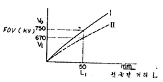
제9도에 있어서, 상기 역섬락 및 암전류에 의한 방전은 방지된다. 이 실시태양에서, 창(98)은 접지 탱크의 고전압 도체(58)와 측면에 설치되며, 자외선, 방사선 및 레이저비임과 같은 비임은 조사장치(수은램프, 레이저 발진기 등)에서 상기 창(98)을 통하여 전극(62)간의 지대로 조사될 수 있으며, 제10도는 전극간의 지대로 비임조사의 유무에 관련하여 전극간 방전특성을 나타낸다.In FIG. 9, the reverse flashover and the discharge due to the dark current are prevented. In this embodiment, the
제10도에 있어서, 실선(I)과 파선(Ⅱ)은 전혀 비임이 조사되지 않고 광비임이 조사될 경우에 전극간 거리 L와 플래시오우버 전압 FOV간의 관계를 가리킨다. 제10도에서 알 수 있는 바와 같이, 동일 전극간 거리 L에 관련하여 광비임을 조사함으로써 약 10%의 플래시오우버 전압을 감소시킬 수 있고, 따라서 조사지대의 가스를 이온화 한다. 예컨대, 300KV급 장치에 있어서, 전극간 거리가 L1(500mm)에 세트될 때, 광비임을 조사함으로써 플래시오우버 전압을 Vo(750KV)에서 Vi(670KV)를 감소시킬 수 있다. 즉, 전극간 거리 L1의 경우, 제11a도에 표시된 전원전압은 가동전극에 인가된다. 이때, 조사장치(96)에서 가동전극(62)까지의 조사는 플래시오우버 전압을 Vo에서 Vi로 감소시키고, 따라서 방전은 시간 t1(제11b도)에서 개시된다. 이리하여 전압 Vi은 부하측에 가해진다. 이러한 상태에서 광비임은 가동전극에만 조사되고 고정전극에는 전혀 비임이 조사되지 않으며, 따라서 고정전극에서 가동전극으로의 방전에 필요한 전압은 Vo이고, 결과적으로 역섬락은 발생하지 않을 것이다.In FIG. 10, the solid line I and the broken line II indicate the relationship between the distance L between the electrodes and the flashover voltage FOV when no light beam is irradiated and no light beam is irradiated. As can be seen in FIG. 10, by irradiating light beams with respect to the distance L between the same electrodes, a flashover voltage of about 10% can be reduced, thus ionizing the gas in the irradiation zone. For example, in a 300KV class apparatus, when the distance between electrodes is set to L 1 (500mm), the flashover voltage can be reduced from Vo (750KV) to Vi (670KV) by irradiating light beams. That is, in the case of the inter-electrode distance L 1 , the power supply voltage shown in FIG. 11A is applied to the movable electrode. At this time, the irradiation from the
가동 및 고정전극간의 지대에 비임이 조사되는 경우를 기술하면 다음과 같다. 이 경우에 가동전극에서 고정전극으로 방전시키키는 플래시오우버 전압과 고정전극에서 가동전극으로의 방전에 필요한 플래시오우버 전압은 Vo에서 Vi로 감소된다. 따라서 첫 번 방전을 위하여 광비임은 전원전압 Vs(제11a도의 시간 t0~t1에 대응한)의 파두부가 존재할 때에만 조사장치(96)에서 조사된다. 이때 t1에서 가동전극에서 고정전극으로 방전이 발생하며, 따라서 전압 Vi은 부하측에 가해진다. 비임조사는 이제 끝나고, 고정전극에서 가동전극으로의 방전을 위한 플래시오우버 전압은 Vo로 증가하며, 따라서 역섬락은 발생하지 않는다. 조사장치(96)는 전원전압 Vs이 인가될 때의 시간과 동기된 시동기(48)로부터의 트리거신호에 대응하여 소정시간 t0~t1만 광비임을 조사한다.The case where the beam is irradiated to the zone between the movable and fixed electrode is as follows. In this case, the flashover voltage for discharging from the movable electrode to the fixed electrode and the flashover voltage for discharging from the fixed electrode to the movable electrode are reduced from Vo to Vi. Therefore, for the first discharge, the light beam is irradiated from the
다음은 역섬락은 전원전압 Vs이 이온화 가스가 완전히 반응하기전 거의 영으로될 때 발생한다. 따라서 전압 Vs이 역섬락을 방지하기 위하여 상기 이온화 가스가 완전히 반응한 후, 거의 영으로 되도록 전원전압 Vs의 파미를 충분히 길게하는 것이 바람직하다.Next, reverse flashover occurs when the supply voltage Vs is near zero before the ionizing gas has fully reacted. Therefore, in order to prevent the reverse flashover of the voltage Vs, it is preferable to lengthen the wave of the power supply voltage Vs sufficiently long so that the ionizing gas is completely reacted.
제12도에는 역섬락 및 암전류에 의한 방전이 방지되는 시험방법이 도시되어 있다. 이 실시태양에서 제6도에 도시된 가동전극(62)의 선단내부는 파내어 있으며, 절연지지부재(100)에 의하여 지지되어 있는 도전 트리거전극(102)이 부착되어 있다. 상기 구성으로 전원전압 Vs이 전원에서 가동전극으로 가해질 때, 전위차는 정전용량에 의하여 트리거전극(102)과 가동전극(62) 사이의 파두부(이는 제11a도의 시간 t0~t1에 대응한)에서 발생하며, 따라서 방전은 이 사이에서 발생한다. 이리하여 이 방전에 의하여 가동전극에서 고정전극으로의 방전을 위한 플래시오우버 전압은 약 10%씩 감소되어, 전원전압 Vs의 저레벨(즉, 제11a도의 시간 t1에서 Vi)에서 전극간 방전을 하게 하며 따라서 상기 전압 Vi은 부하측에 가해진다. 일단 방전이 발생하면, DC 전계는 트리거전극과 가동전극 사이에서 발생하며, 따라서 전위차는 소멸될 것이다. 그러므로 전극간 방전이 개시됨과 동시에 트리거전극과 가동전극간의 방전은 소멸하고, 이로 인하여 전극간의 플래시오우버 전압을 Vo로 증가시킨다. 이리하여 고정전극으로부터 가동전극으로의 방전을 위한 플래시오우버 전압은 Vo로 되고, 따라서 역섬락을 방지할 수 있다.12 shows a test method in which discharge due to reverse flashover and dark current is prevented. In this embodiment, the tip inner portion of the movable electrode 62 shown in FIG. 6 is dug, and the
상기 각 실시 태양에 있어서, 전원전압은 -Vi(-1PU)은 제2방전을 행할 때, 단로기에 인가되고 이리하여 대지절연 시험을 실시한다. 제1 및 제2방전에 있어서의 전극간 거리는 동일합며, 또는 제2방전의 거리는 제1방전시 보다 길어도 된다.In each of the above embodiments, a power supply voltage of -Vi (-1PU) is applied to the disconnector when performing the second discharge, and thus, the earth insulation test is performed. The distance between the electrodes in the first and second discharges may be the same, or the distance between the second discharges may be longer than during the first discharge.
동일 전원전압이 사용될 경우, 전극간 거리는 제1방전시의 광비임을 조사하여 또는 상기와 같이 가동 및 트리거전극을 실설치함으로써 길게 세트할 수 있다. 그러므로 아무런 변동 없이 안정잔류 전압을 형성할 수 있다.When the same power supply voltage is used, the distance between the electrodes can be set long by irradiating the light beam at the first discharge or by installing the movable and trigger electrodes as described above. Therefore, a stable residual voltage can be formed without any change.
상기 실시태양에 있어서, 가동전극이 전원측에 사용되었으나 부하측에는 가동전극을 전원측에는 고정전극을 사용할 수가 있다.In the above embodiment, the movable electrode is used on the power supply side, but the movable electrode on the load side and the fixed electrode on the power supply side can be used.
제12도의 실시태양에는 가동전극에 트리거전극이 설치되어 있으나 고정전극을 설치해도 된다.In the embodiment of Fig. 12, the trigger electrode is provided on the movable electrode, but a fixed electrode may be provided.
상기 방법에 의하면, 직류전압 잔류후의 역섬락 또는 암전류에 의한 방전이 용이하게 방지되므로 직류잔류전압의 제어가 용이하게 행해지고, 이리하여 시험의 효율이 향상된다.According to the above method, since discharge due to reverse flashover or dark current after DC voltage remaining is easily prevented, control of the DC residual voltage is easily performed, thereby improving the efficiency of the test.
본 발명에 의하면, 단로기의 충전전류 차단시, 대지절연검증은 단일전원과 단일부싱을 사용하여 소규모 설비로 행할 수 있다. 그러므로 이 적용효과는 정격전압의 높은 단로기일수록 크며, 특히 UHV급의 단로기에 있어서는 부싱의 가격이 매우 고가이므로 본 발명은 부싱 한계로서 족한 시험법으로서 그 효과는 큰 것이다.According to the present invention, when the charging current of the disconnector is cut off, the ground insulation verification can be performed in a small facility using a single power supply and a single bushing. Therefore, this application effect is larger the higher the disconnection voltage of the rated voltage, especially in the case of UHV class disconnectors, because the price of the bushing is very expensive, the present invention is a test method that satisfies the bushing limit, the effect is large.
Claims (9)
Applications Claiming Priority (2)
| Application Number | Priority Date | Filing Date | Title |
|---|---|---|---|
| JP143417 | 1980-10-13 | ||
| JP57143417A JPS5934170A (en) | 1982-08-20 | 1982-08-20 | Anti-ground insulation inspection testing method in case when charging current of disconnecting switch is cut off |
Publications (2)
| Publication Number | Publication Date |
|---|---|
| KR840006077A KR840006077A (en) | 1984-11-21 |
| KR890000692B1 true KR890000692B1 (en) | 1989-03-24 |
Family
ID=15338268
Family Applications (1)
| Application Number | Title | Priority Date | Filing Date |
|---|---|---|---|
| KR1019830003846A KR890000692B1 (en) | 1982-08-20 | 1983-08-17 | Method of testing and verifying a performance for insulation to ground of a disconnecting switch when breaking a charging current |
Country Status (9)
| Country | Link |
|---|---|
| US (1) | US4549132A (en) |
| EP (1) | EP0103758B1 (en) |
| JP (1) | JPS5934170A (en) |
| KR (1) | KR890000692B1 (en) |
| AU (1) | AU544370B2 (en) |
| CA (1) | CA1205860A (en) |
| DE (1) | DE3379980D1 (en) |
| IN (1) | IN160109B (en) |
| ZA (1) | ZA836141B (en) |
Families Citing this family (11)
| Publication number | Priority date | Publication date | Assignee | Title |
|---|---|---|---|---|
| JPS6319570A (en) * | 1986-07-11 | 1988-01-27 | Hitachi Ltd | Testing voltage generator for gas insulating apparatus |
| JP2618049B2 (en) * | 1989-08-25 | 1997-06-11 | 三菱電機株式会社 | Transformers for optical instruments |
| EP0491554B1 (en) * | 1990-12-17 | 1996-05-22 | Patented Devices (Proprietary) Limited | Monitoring partial discharges |
| DE19648643A1 (en) * | 1996-11-25 | 1998-05-28 | Asea Brown Boveri | Metal encapsulated gas insulated switchgear enclosure with earthing |
| US6084756A (en) * | 1999-01-22 | 2000-07-04 | Eaton Corporation | Apparatus for testing protection of an electric power distribution circuit by an arc fault circuit breaker |
| CN101881813B (en) * | 2010-06-17 | 2013-12-04 | 国网电力科学研究院 | Method for simulating GIS transformer substation to produce very fast transient overvoltage (VFTO) and test circuit |
| CN102073003B (en) * | 2011-02-16 | 2012-08-08 | 上海思源高压开关有限公司 | Insulation test tool for gas-insulated metal-enclosed switchgear (GIS) |
| CN103149545B (en) * | 2013-01-29 | 2016-05-11 | 华北电力大学 | The method of testing of VFTO sensor, device, equipment and system |
| US9664716B1 (en) | 2013-03-15 | 2017-05-30 | Meg-Alert, Inc. | Automatic insulation resistance testers |
| CN104360241B (en) * | 2014-09-26 | 2015-11-18 | 国家电网公司 | Gas-insulated impulse voltage generator unit impacts resistance characteristics pilot system and method |
| CN107817428B (en) * | 2017-11-10 | 2024-04-26 | 北京动力源科技股份有限公司 | Bus insulation detection circuit and method |
Family Cites Families (5)
| Publication number | Priority date | Publication date | Assignee | Title |
|---|---|---|---|---|
| US2923879A (en) * | 1955-01-10 | 1960-02-02 | Doble Eng | Insulation testing apparatus |
| US2916697A (en) * | 1955-07-05 | 1959-12-08 | Bourns Inc | Insulation resistance measuring circuit |
| US2977531A (en) * | 1958-11-18 | 1961-03-28 | Westinghouse Electric Corp | Insulation test circuit |
| CH592314A5 (en) * | 1975-11-28 | 1977-10-31 | Bbc Brown Boveri & Cie | |
| DE2638678B1 (en) * | 1976-08-25 | 1978-01-26 | Siemens Ag | Synthetic check circuit |
-
1982
- 1982-08-20 JP JP57143417A patent/JPS5934170A/en active Granted
-
1983
- 1983-08-15 US US06/523,086 patent/US4549132A/en not_active Expired - Lifetime
- 1983-08-16 CA CA000434727A patent/CA1205860A/en not_active Expired
- 1983-08-17 KR KR1019830003846A patent/KR890000692B1/en not_active IP Right Cessation
- 1983-08-17 AU AU18076/83A patent/AU544370B2/en not_active Ceased
- 1983-08-17 IN IN1011/CAL/83A patent/IN160109B/en unknown
- 1983-08-18 DE DE8383108179T patent/DE3379980D1/en not_active Expired
- 1983-08-18 EP EP83108179A patent/EP0103758B1/en not_active Expired
- 1983-08-19 ZA ZA836141A patent/ZA836141B/en unknown
Also Published As
| Publication number | Publication date |
|---|---|
| AU544370B2 (en) | 1985-05-23 |
| AU1807683A (en) | 1984-02-23 |
| JPS5934170A (en) | 1984-02-24 |
| KR840006077A (en) | 1984-11-21 |
| CA1205860A (en) | 1986-06-10 |
| JPH0363027B2 (en) | 1991-09-27 |
| EP0103758A3 (en) | 1985-08-28 |
| EP0103758B1 (en) | 1989-05-31 |
| IN160109B (en) | 1987-06-27 |
| EP0103758A2 (en) | 1984-03-28 |
| US4549132A (en) | 1985-10-22 |
| ZA836141B (en) | 1984-04-25 |
| DE3379980D1 (en) | 1989-07-06 |
Similar Documents
| Publication | Publication Date | Title |
|---|---|---|
| Yamagata et al. | Suppression of VFT in 1100 kV GIS by adopting resistor-fitted disconnector | |
| KR890000692B1 (en) | Method of testing and verifying a performance for insulation to ground of a disconnecting switch when breaking a charging current | |
| KR950013413B1 (en) | Insulation testing device for gas insulated apparatus | |
| Narimatsu et al. | Interrupting performance of capacitive current by disconnecting switch for gas insulated switchgear | |
| Osmokrovic et al. | Numerical and experimental design of three-electrode spark gap for synthetic test circuits | |
| US4147975A (en) | Synthetic test circuit for a metal encapsulated high voltage circuit breaker | |
| Nishiwaki et al. | Ground Fault by Restriking Surge of SF6 Gas-Insulated Disconnecting Switching and its Synthetic Tests | |
| Szewczyk et al. | Impact of disconnector design on very fast transient overvoltages in gas-insulated UHV switchgear | |
| US4286301A (en) | H.V. current cut-out circuit | |
| Tokoyoda et al. | DC current interruption tests with HV mechanical DC circuit breaker | |
| Nakano et al. | Field emission inception voltage of a 72.5 kV VI with controlled vapor shield potential | |
| Rowe | GIS disconnectors: A physical model for ground faulting | |
| Götte et al. | Switching behaviour of a series connection of a vacuum interrupter and a gas circuit breaker | |
| Tomiyasu et al. | Evaluation of efficient electrode conditioning method for vacuum interrupters | |
| Inagaki et al. | Study on Post-Arc Current of DC Current Interruption Using Vacuum Interrupter | |
| Strang et al. | Field tests on high-capacity air-blast station-type circuit breakers | |
| JP2666946B2 (en) | Capacitor switching performance test equipment | |
| JPH0560062B2 (en) | ||
| SU938223A1 (en) | Device for synthetic testing of switches for switching-off capability | |
| Oh-Hara et al. | Line Entrance Protection of 500 KV Gas Insulated Substations by SF6 Spark Gaps | |
| JPS61101926A (en) | Refiring surge test for gas-insulated switch gear | |
| JPS59220663A (en) | Reignition surge testing method of gas insulated disconnecting switch | |
| Ponsonby et al. | The effect of surface charge on the performance of cast resin insulation for gas insulated substations | |
| SU116166A2 (en) | Device for testing high-voltage circuit breakers for switching capacity | |
| Lalot et al. | Dielectric behavior of GIS switching disconnectors comparison of possible phase opposition tests |
Legal Events
| Date | Code | Title | Description |
|---|---|---|---|
| A201 | Request for examination | ||
| G160 | Decision to publish patent application | ||
| E701 | Decision to grant or registration of patent right | ||
| GRNT | Written decision to grant | ||
| FPAY | Annual fee payment |
Payment date: 20020307 Year of fee payment: 14 |
|
| LAPS | Lapse due to unpaid annual fee |