KR890000347B1 - Refrigeration system - Google Patents
Refrigeration system Download PDFInfo
- Publication number
- KR890000347B1 KR890000347B1 KR1019840002856A KR840002856A KR890000347B1 KR 890000347 B1 KR890000347 B1 KR 890000347B1 KR 1019840002856 A KR1019840002856 A KR 1019840002856A KR 840002856 A KR840002856 A KR 840002856A KR 890000347 B1 KR890000347 B1 KR 890000347B1
- Authority
- KR
- South Korea
- Prior art keywords
- gas
- liquid separator
- pipe
- reducer
- heating
- Prior art date
Links
Images


Classifications
-
- F—MECHANICAL ENGINEERING; LIGHTING; HEATING; WEAPONS; BLASTING
- F25—REFRIGERATION OR COOLING; COMBINED HEATING AND REFRIGERATION SYSTEMS; HEAT PUMP SYSTEMS; MANUFACTURE OR STORAGE OF ICE; LIQUEFACTION SOLIDIFICATION OF GASES
- F25B—REFRIGERATION MACHINES, PLANTS OR SYSTEMS; COMBINED HEATING AND REFRIGERATION SYSTEMS; HEAT PUMP SYSTEMS
- F25B1/00—Compression machines, plants or systems with non-reversible cycle
-
- F—MECHANICAL ENGINEERING; LIGHTING; HEATING; WEAPONS; BLASTING
- F25—REFRIGERATION OR COOLING; COMBINED HEATING AND REFRIGERATION SYSTEMS; HEAT PUMP SYSTEMS; MANUFACTURE OR STORAGE OF ICE; LIQUEFACTION SOLIDIFICATION OF GASES
- F25B—REFRIGERATION MACHINES, PLANTS OR SYSTEMS; COMBINED HEATING AND REFRIGERATION SYSTEMS; HEAT PUMP SYSTEMS
- F25B13/00—Compression machines, plants or systems, with reversible cycle
-
- F—MECHANICAL ENGINEERING; LIGHTING; HEATING; WEAPONS; BLASTING
- F25—REFRIGERATION OR COOLING; COMBINED HEATING AND REFRIGERATION SYSTEMS; HEAT PUMP SYSTEMS; MANUFACTURE OR STORAGE OF ICE; LIQUEFACTION SOLIDIFICATION OF GASES
- F25B—REFRIGERATION MACHINES, PLANTS OR SYSTEMS; COMBINED HEATING AND REFRIGERATION SYSTEMS; HEAT PUMP SYSTEMS
- F25B41/00—Fluid-circulation arrangements
-
- F—MECHANICAL ENGINEERING; LIGHTING; HEATING; WEAPONS; BLASTING
- F25—REFRIGERATION OR COOLING; COMBINED HEATING AND REFRIGERATION SYSTEMS; HEAT PUMP SYSTEMS; MANUFACTURE OR STORAGE OF ICE; LIQUEFACTION SOLIDIFICATION OF GASES
- F25B—REFRIGERATION MACHINES, PLANTS OR SYSTEMS; COMBINED HEATING AND REFRIGERATION SYSTEMS; HEAT PUMP SYSTEMS
- F25B2400/00—General features or devices for refrigeration machines, plants or systems, combined heating and refrigeration systems or heat-pump systems, i.e. not limited to a particular subgroup of F25B
- F25B2400/13—Economisers
-
- F—MECHANICAL ENGINEERING; LIGHTING; HEATING; WEAPONS; BLASTING
- F25—REFRIGERATION OR COOLING; COMBINED HEATING AND REFRIGERATION SYSTEMS; HEAT PUMP SYSTEMS; MANUFACTURE OR STORAGE OF ICE; LIQUEFACTION SOLIDIFICATION OF GASES
- F25B—REFRIGERATION MACHINES, PLANTS OR SYSTEMS; COMBINED HEATING AND REFRIGERATION SYSTEMS; HEAT PUMP SYSTEMS
- F25B2400/00—General features or devices for refrigeration machines, plants or systems, combined heating and refrigeration systems or heat-pump systems, i.e. not limited to a particular subgroup of F25B
- F25B2400/23—Separators
-
- F—MECHANICAL ENGINEERING; LIGHTING; HEATING; WEAPONS; BLASTING
- F25—REFRIGERATION OR COOLING; COMBINED HEATING AND REFRIGERATION SYSTEMS; HEAT PUMP SYSTEMS; MANUFACTURE OR STORAGE OF ICE; LIQUEFACTION SOLIDIFICATION OF GASES
- F25B—REFRIGERATION MACHINES, PLANTS OR SYSTEMS; COMBINED HEATING AND REFRIGERATION SYSTEMS; HEAT PUMP SYSTEMS
- F25B2600/00—Control issues
- F25B2600/25—Control of valves
- F25B2600/2509—Economiser valves
Abstract
Description
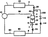
제1도는 본 발명의 한 실시예를 나타내는 냉동 장치의 냉매회로도.1 is a refrigerant circuit diagram of a refrigeration apparatus showing one embodiment of the present invention.
제2도는 다른 실시예를 나타내는 냉동 장치의 냉매회로도.2 is a refrigerant circuit diagram of a refrigeration apparatus showing another embodiment.
제3도는 또 다른 실시예를 나타내는 냉동 장치의 냉매회로도.3 is a refrigerant circuit diagram of a refrigeration apparatus according to another embodiment.
제4도는 또 다른 실시예를 나타내는 냉동 장치의 냉매회로도.4 is a refrigerant circuit diagram of a refrigeration apparatus according to another embodiment.
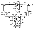
제5도는 또 다른 실시예를 나타내는 냉동 장치의 히트 펌프식 냉매회로도.5 is a heat pump type refrigerant circuit diagram of a refrigerating device according to still another embodiment.
제6도는 또 다른 실시예를 나타내는 냉동 장치의 히트 펌프식 냉매회로도.6 is a heat pump type refrigerant circuit diagram of a refrigerating device according to still another embodiment.
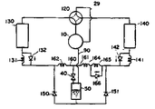
제7도는 또한 다른 실시예를 나타내는 냉동 장치의 열펌프식 냉매회로도이다.7 is also a heat pump type refrigerant circuit diagram of a refrigerating device showing another embodiment.
* 도면의 주요부분에 대한 부호의 설명* Explanation of symbols for main parts of the drawings
10 : 압축기 20 : 응축기10
3,7,8,11,29,23,21 : 배관 30 : 제1감압기3,7,8,11,29,23,21 Pipe 30: First reducer
40 : 전자밸브 50 : 기액 분리기40: solenoid valve 50: gas-liquid separator
51 : 기체실 52 : 액체실51: gas chamber 52: liquid chamber
60 : 역지벨브 70 : 제2감압기60: check valve 70: second reducer
80 : 증발기 90 : 주입관로80: evaporator 90: injection pipe
100 : 바이패스관로 110 : 전자밸브100: bypass pipe 110: solenoid valve
111 : 보조감압기 120 : 사방밸브111: auxiliary reducer 120: four-way valve
130 : 실외열교환기 140 : 실내열교환기130: outdoor heat exchanger 140: indoor heat exchanger
본 발명은 공기조화기(調和機)등에 사용되는 냉동 장치이며, 가스 주입관로로 냉매회로를 형성시킨 냉동장치에 관한 것이다.BACKGROUND OF THE
개스주입관로들로 이루어진 냉매회로를 구비한 냉동 장치는 압축기, 응축기 제1감압기(減壓器), 기액(氣液)분리기, 제2감압기, 증발기를 순차적으로 배관 접속하여 냉매회로를 형성하고 상기 기액 분리기의 상부에 배관을 접속하고 다른끝을 압축기의 실린더 도중에 있는 압축과정의 압축실로 연통되게 접속하여 가스주입관로를 형성하고 있다.A refrigeration unit having a refrigerant circuit composed of gas injection pipes forms a refrigerant circuit by sequentially connecting a compressor, a condenser, a first reducer, a gas-liquid separator, a second reducer, and an evaporator. The pipe is connected to the upper part of the gas-liquid separator, and the other end is connected to the compression chamber of the compression process in the middle of the cylinder of the compressor to form a gas injection pipe.
압축기로부터 토출된 고압가스 냉매는 응축기로 유입(流入)되면서, 그곳에서 유통유체(流通有體)(공기 또는 물)에 방열하여 응축하고 액체냉매가 된다. 응축기를 유출한 액체 냉매는 제1차의 감압기를 거쳐서 중간 압력까지 감압되어, 일부는 가스화하고 기액 분리기로 유입되면서 기액이 분리된다.The high-pressure gas refrigerant discharged from the compressor flows into the condenser, where it radiates to a circulation fluid (air or water), condenses, and becomes a liquid refrigerant. The liquid refrigerant flowing out of the condenser is decompressed to a medium pressure through the primary pressure reducer, and part of the gas is separated into gas gas and flows into the gas-liquid separator.
액체냉매는 기액 분리기의 저부로부터 유출되고 제2차의 감압기를 거쳐서 소정 압력까지 감압되어 증발기에 유입되고, 증발기에서 유통유체(공기 또는 물)에서 흡열(吸熱)하여 가스냉매가 되고, 압축기로 복귀한다.The liquid refrigerant flows out from the bottom of the gas-liquid separator, passes through the secondary pressure reducer to a predetermined pressure, flows into the evaporator, and is absorbed by the flow fluid (air or water) in the evaporator to become a gas refrigerant, and returns to the compressor. do.
한편 상술한 기액 분리기에서 기액 분리되며, 분리기의 상승부에 잔류된 가스냉매는 가스주입관로를 거쳐 압축기의 압축과정중의 압축실에 주입되어, 난방 혹은 냉방능력을 증가한다. 그러나 기액 분리기에서 분리된 가스 냉매를 항상 압축기에 주입하는 구조에서는 부하가 클 경우에는 토출압력 및 토출온도가 과도하게 상승하면서 운전 효율이 저하됨과 동시에 압축기, 전동기의 온도상승 등에 의해 기기의 신뢰성을 저하시킨다.Meanwhile, gas-liquid separated in the above-described gas-liquid separator, and the gas refrigerant remaining in the riser of the separator is injected into the compression chamber during the compression process of the compressor through the gas injection pipe, thereby increasing the heating or cooling capacity. However, in the structure in which the gas refrigerant separated from the gas-liquid separator is always injected into the compressor, when the load is large, the discharge pressure and the discharge temperature are excessively increased, the operation efficiency is lowered, and the reliability of the device is lowered due to the temperature rise of the compressor and the motor. Let's do it.
그러므로 주입관로의 개폐밸브를 설치하여 과부하(過負荷)시에는 차단하는 방식이 특공소 55-47296호로서 제안되고 있으나 이 방식으로는 가스 주입을 행할 경우를 기준으로 하여 제1 및 제2감압기의 감압 저항을 설정하였을때 가스주입관로를 차단하여 가스 주입을 하지 않은 냉매회로로서 운전하며, 가스 주입 운전에 비하여 제1감압기의 유량이 감소하기 때문에 제2감압기의 저항이 지나치게 작아지면서 압축기로 액체가 복귀하는 운전상태로 된다. 이 때문에 냉동 능력 저하 또는 운전 효율의 저하를 가져오는 등의 문제점을 가지고 있었다.Therefore, it is proposed as a special public office 55-47296 to install the on-off valve of the injection pipe and block it in case of overload. However, in this method, the first and the second reducer are based on the case of gas injection. When the decompression resistance is set, the gas injection line is blocked to operate as a refrigerant circuit without gas injection, and the flow rate of the first reducer decreases as compared to the gas injection operation. The liquid is returned to the operating state. For this reason, there existed a problem, such as a fall of freezing capability or a fall of operation efficiency.
또한 가스 주입을 행하는 냉매회로와 가스 주입을 하지 않는 냉매회로의 적정한 냉매 순환량은 거의 동등하지만 상기 선행 기술로는 가스 주입을 행하고 있을 때에 기액 분리기내에 괴인 액체 냉매가 가스주입관로를 차단함으로써 냉매시에는 기액 분리기가 외기에 의해 따뜻해져서 기내의 액체 냉매가 증발하여 유출되므로, 외관상 냉매 순환량이 많은 상황이 되는데 이 때문에 냉매 순환량을 적절하게 하기 위하여 잉여 냉매를 저장하기 위한 냉매조정용 탱크가 필요하게 되는 문제점도 갖고 있다.In addition, although the proper amount of refrigerant circulation between the refrigerant circuit for gas injection and the refrigerant circuit without gas injection is almost the same, the above-described prior art uses a liquid refrigerant accumulated in a gas-liquid separator to block the gas injection pipe when the gas is injected. Since the gas-liquid separator is warmed by the outside air and the liquid refrigerant in the aircraft evaporates and flows out, there is a large amount of refrigerant circulation in appearance. Therefore, a refrigerant adjustment tank for storing the excess refrigerant is required to properly regulate the refrigerant circulation. Have
또 다른 선행 기술로서 가스주입관로에 개폐밸브를 마련하지 않고 가스 주입을 하지 않는 운전시에는 냉매 유로를 기액 분리기로 흐르게 하고 동시에 기액 분리기를 바이패스하여 흐를 수 있게 분류되도록 한 것이 실개소 57-68454호에 기재되어있으나, 이 방식의 것은 가스 주입을 하지 않을 경우도 일부의 냉매가 기액 분리기 내를 통과하여 증발기를 향해 흐르므로 기액 분리기에는 잉여 냉매를 저장하는 기능이 있어야 함에도 이러한 기능이 없는 등의 문제점을 가진다.As another prior art, in the case where the gas injection pipe is not provided with an on-off valve and the gas is not injected, the refrigerant path flows to the gas-liquid separator and at the same time, the gas-liquid separator is bypassed and classified to flow. Although this type of method is described, some of the refrigerant flows through the gas-liquid separator and flows toward the evaporator even when no gas is injected, but the gas-liquid separator must have a function of storing surplus refrigerant. I have a problem.
본 발명의 목적은 냉매회로의 부하에 동등하여 가스 주입을 행하는 냉매회로와 가스 주입을 행하지 않는 냉매회로에 대한 절환이 가능하며, 또한 상기 각 냉매회로에 적합한 냉매 유량 제어를 행할 수 있는 냉매회로를 제공하며, 본 발명의 다른 목적은 높은 부하시의 토출압력 및 토출온도의 상승을 방지함은 물론 가스 주입을 행하지 않을 때에는 압축기로 액체 복귀를 방지할 수 있는 냉매회로를 제공 하는 데 있다.An object of the present invention is to switch between a refrigerant circuit that performs gas injection and a refrigerant circuit that does not perform gas injection, which is equivalent to the load of the refrigerant circuit, and a refrigerant circuit capable of controlling the flow rate of refrigerant suitable for each of the refrigerant circuits. Another object of the present invention is to provide a refrigerant circuit capable of preventing a rise in discharge pressure and discharge temperature at high load, as well as preventing liquid return to the compressor when gas injection is not performed.
상기 목적을 달성하기 위하여 본 발명은 압축기, 응축기, 제1감압기, 기액 분리기, 제2감압기 및 증발기를 순차적으로 배관 접속한 주 냉매회로와 기액 분리기의 기체실과 압축기의 압축실을 배관 접속하는 주입 관로를 구비한 냉매회로에 있어서, 기액 분리기의 출입구 관로에 순환냉매를 주입할 때는 개방되고, 주입하지 않을 때에는 폐쇄되는 개폐수단을 설치하고 응축기 출구 관로와 증발기 입구 관로와의 사이에 기액 분리기를 바이패스하는 바이패스 관로를 설치하며, 주입하지 않을 때 순환냉매가 기액 분리기를 바이패스하여 바이패스 관로를 흐르게 함과 동시에 기액 분리기를 냉매량 조절탱크로서 작동시키는 구성을 가진다.In order to achieve the above object, the present invention provides a pipe connection between the main refrigerant circuit and the gas chamber of the gas-liquid separator and the compression chamber of the compressor, which are connected to the compressor, the condenser, the first reducer, the gas-liquid separator, the second reducer, and the evaporator sequentially. In a refrigerant circuit having an injection pipe, an opening / closing means which is opened when injecting circulating refrigerant into the inlet pipe of the gas-liquid separator and closed when not injected is installed, and a gas-liquid separator is disposed between the condenser outlet pipe and the evaporator inlet pipe. By-pass bypass pipe is installed, and when not injected, the circulating refrigerant bypasses the gas-liquid separator to flow the bypass pipe, and at the same time, the gas-liquid separator is configured as a refrigerant amount control tank.
또 다른 실시예에서는, 압축기, 사방밸브, 실외 열교환기, 역지(CHECK) 밸브를 병설한 난방용 감압기, 기액 분리기, 역지 밸브를 병설한 냉방용 감압기, 실내 열교환기를 순차적으로 배관 접속하고, 냉·난방에 따라 사방 밸브를 절환하여 압축기의 토출관로 및 흡입관로를 상기 실외 열교환기 및 실내 열교환기에 서로 절환접속하는 열 펌프식 냉매회로와, 기액 분리기의 기체실과, 압축기의 압축실을 배관 접속하는 주입 관로를 구비한 냉매회로에 있어서, 상기 난방용 감압기를 난방용 제2감압기로 작동시키고 냉방용 감압기를 냉방용 제3감압기로서 작동시켜 기액 분리기의 입구관로에 순환냉매를 주입할 때는 개방되게 하고, 주입하지 않을 때는 폐쇄하는 개폐밸브를 설치하므로, 냉방시에는 실외 열교환기의 출구측으로부터 상기의 역지 밸브를 거쳐 냉방용 제1감압기와 기액 분리기 입구측 개폐밸브를 거쳐 기액 분리기에 접속되면서 기액 분리기의 저부로부터 역지 밸브를 거쳐 상기 냉방용 제2감압기에 접속되는 관로를 형성하고, 난방시에는 실내 열교환기의 출구측에서 상기 역지 밸브를 거쳐, 난방용 제1감압기, 상기 기액 분리기의 입구측 개폐밸브를 거쳐서 기액 분리기에 접속되며, 기액 분리기의 저부로부터 역지 밸브를 거쳐 상기 난방용 제2감압기에 접속되는 관로를 형성하고, 주입하지 않은 때의 냉방시에는 냉방용 제1감압기와, 냉방용 제2감압기와의 사이에 기액 분리기를 바이패스 하는 냉방용 바이패스 관로와 난반시에는 난방용 제1감암기와 난방용 제2감압기와의 사이에 기약 분리기를 바이패스 하는 난방용 바이패스 관로를 설치하여, 주입하지 않을때 순환냉매가 기액 분리기를 바이패스 하여 냉방용 바이패스 관로 혹은 난방용 바이패스 관로를 흐름과 동시에 기액 분리기를 냉매량 조절탱크로서 작동시키는 구성을 가진다.In still another embodiment, a compressor, a four-way valve, an outdoor heat exchanger, a heating pressure reducer including a check valve, a gas-liquid separator, a cooling pressure reducer including a check valve, and an indoor heat exchanger are sequentially connected to each other. A pipe for connecting a heat pump-type refrigerant circuit, a gas chamber of a gas-liquid separator, and a compression chamber of a compressor to switch between four-way valves according to heating to switch the discharge and suction lines of the compressor to the outdoor heat exchanger and the indoor heat exchanger. In the refrigerant circuit having an injection pipe, the heating pressure reducer is operated as a second heating reducer and the cooling pressure reducer is operated as a cooling third pressure reducer to open when injecting circulating refrigerant into the inlet pipe of the gas-liquid separator. When it is not injected, an on-off valve is provided that closes. Therefore, during cooling, the check valve is discharged from the outlet side of the outdoor heat exchanger. The first pressure reducer and the gas-liquid separator are connected to the gas-liquid separator via the inlet / opening valve of the gas-liquid separator and form a conduit from the bottom of the gas-liquid separator to the cooling second pressure reducer via the check valve. Is connected to the gas-liquid separator via the check valve, the first pressure reducer for heating and the inlet-side opening / closing valve of the gas-liquid separator, and forms a conduit connected from the bottom of the gas-liquid separator via the check valve to the second pressure reducer for heating. The cooling bypass line which bypasses the gas-liquid separator between the cooling first reducer and the cooling second reducer when cooling without injection, and the heating first damper for heating and second pressure reducing for heating. A heating bypass pipe for bypassing the separator is installed between the roof and the circulating refrigerant to replace the gas-liquid separator when it is not injected. Pass by having a configuration to operate the gas-liquid separator as the refrigerant amount control tank at the same time as the flow of cooling or heating bypass line bypass line for.
상기와 같이 가스를 주입하지 않는 운전시는 순환 냉매는 기액 분리기를 바이패스하여 바이패스 관로를 흐르고 또 기액 분리기는 냉매량 조절탱크로서의 기능을 가진다.In the operation without gas injection as described above, the circulating refrigerant bypasses the gas-liquid separator and flows through the bypass pipe, and the gas-liquid separator functions as a refrigerant amount control tank.
즉, 가스를 주입하지 않는 운전상태에서는 제1감압기, 보조감압기와 제2감압기가 직렬로 접속되므로 3개의 감압기에 의해 유통냉매를 소정의 저압으로 감압시킨다.That is, in the operating state in which gas is not injected, the first reducer, the auxiliary reducer, and the second reducer are connected in series, so that the circulation refrigerant is reduced to a predetermined low pressure by the three pressure reducers.
가스 주입을 하지 않은 냉매회로에서는 가스 주입을 행하는 냉매회로에 비교하여 제1감압기를 유통하는 냉매 유량(流量)이 적기 때문에 냉매 순환량을 적절히 제어하기 위해서는 유통저항을 크게할 필요가 있으나, 주입을 하지 않은 운전시에는 바이패스 관로의 보조감압기가 보조 작동하여 냉매회로 전체의 유통저항을 가장 적절히 설정하고 증발기 출구측의 순환 냉매의 건조도를 최적하게 유지시킬 수 있다.In the refrigerant circuit without gas injection, the flow rate of the refrigerant flowing through the first reducer is less than that of the gas circuit in which gas injection is performed. Therefore, in order to properly control the refrigerant circulation amount, it is necessary to increase the flow resistance. In non-operational operation, the auxiliary reducer of the bypass line is assisted to set the flow resistance of the entire refrigerant circuit most appropriately and to maintain the optimum drying degree of the circulating refrigerant at the outlet side of the evaporator.
또한 순환 냉매량은 가스 주입을 행할때의 냉매회로나, 가스 주입을 행하지 않을때의 냉매회로일 경우에도 그 양이 거의 동일하므로 가스 주입을 하지 않는 운전시에도 기액 분리기내에 액체 냉매가 저장되지 않으며, 상술한 구성에 의해 가스 주입하지 않은 운전시에는 기액 분리기내의 압력은 제2감압기의 입구 압력보다 낮아지게 되며, 또한 기액 분리기의 출입구는 전자 밸브와 역지 밸브로 폐쇄되기 때문에 기액 분리기 내에는 액체 냉매가 그대로 유지되며, 기액 분리기는 냉매량 조절 탱크로서 작동한다.In addition, the amount of circulating coolant is almost the same even in the case of the refrigerant circuit when gas injection or the refrigerant circuit when gas injection is not performed, so that the liquid refrigerant is not stored in the gas-liquid separator even during operation without gas injection. According to the above configuration, in operation without gas injection, the pressure in the gas-liquid separator is lower than the inlet pressure of the second reducer, and since the entrance and exit of the gas-liquid separator is closed by the solenoid valve and the check valve, the liquid refrigerant in the gas-liquid separator Is maintained and the gas-liquid separator operates as a refrigerant amount control tank.
이상 기술한 바와 같이 본 발명에 의하면 가스 주입을 행하는 운전시나 가스 주입을 행하지 않는 운전시에도 적정한 냉매 순환량과 증발기 출구의 냉매 건조도가 거의 적당하게 제어되며, 동시에 부하에 따른 용량제어가 가능하게 된다. 또한 냉동(냉방) 및 난방 능력의 저하의 방지나 토출압력 및 토출온도의 상승 혹은 가스를 주입하지 않은 운전시나 압축기로 액체가 복귀되지 않는다.As described above, according to the present invention, the appropriate refrigerant circulation amount and the refrigerant dryness at the evaporator outlet are almost controlled at the time of the gas injection operation or the operation without the gas injection, and at the same time, the capacity control according to the load is possible. . In addition, liquid is not returned to the compressor during the operation of preventing refrigeration (cooling) and lowering of the heating capacity, increasing the discharge pressure and discharge temperature, or injecting gas.
이하 본 발명의 실시예를 제1도에 나타낸 냉매회로도에 의거하여 설명한다.An embodiment of the present invention will be described below with reference to the refrigerant circuit diagram shown in FIG.
(10)은 압축기이며, 토출측은 토출배관(1)에 의해 응축기(20)에 접속되어 있고, 상기 응축기(20)의 액체라인측은 액체배관(2)에 의해 캐필러리튜브(Capillary tube)등의 제1감압기(30)에 접속되어 있다. (40)은 전자 밸브 등의 개폐수단이며 입구측을 배관(3)에 의해 상기 제1감압기(30)에 접속하고, 출구측을 배관(4)에 의해 기액 분리기(50)의 기체실(51)에 접속한다. (60)은 역지 밸브이며, 입구측을 배관(6)에 의해 상기 기액 분리기(50)의 액체실(52)에 접속되어 있고, 출구측은 배관(7)에 의해 캐필러리튜브등의 제2감압기(70)에 접속되어 있다.10 is a compressor, and the discharge side is connected to the
(80)은 증발기이며, 입구측을 배관(8)에 의해 상기 제2감압기(70)에 접속시키고 출구측이 배관(9)에 의해 상기 압축기(10)의 흡입측에 접속되게 한다. 가스 주입관로(90)은 한쪽끝을 상기 기액 분리기(50) 기체실(51)에 접속시켜 연통되게 하고, 타단은 상기 압축기(10)의 압축실에 접속시켜 연통되게 하고 있다.80 is an evaporator, and the inlet side is connected to the
(100)은 바이패스 관로이며, 전자 밸브(110)와 캐필러리튜브등의 보조감압기(111)가 직열로 접속되어 있다. 그리고 이 바이패스 관로의 한쪽은 상기 배관(3)에 접속되어 있으며, 다른쪽은 상기 배관(7)에 접속되어 있다. 다음에 그 작용을 설명한다.
우선 가스 주입을 행하는 운전에서는 실내온도를 검지하는 센서(도시되지 않음)의 지시에 의해 전자 밸브(40)는 개방되며 전자 밸프(110)는 폐쇄로 되고, 기액 분리기(50)에서 분리된 가스 냉매는 가스 주입 관로(90)를 거쳐 압축기(10)의 압축행정중 압축실내로 주입되고 따라서 그 분량만큼 2배의 능력으로 향상된다. 다음에 주입하지 않은 싸이클의 운전에서는 전자 밸브(40)는 폐쇄되고, 전자 밸프(110)는 개방되어, 응축기(20)에서 액화된 냉매는 제1감압기(30), 보조감압기(111) 및 제2감압기(70)에서 감압되며, 증발기(80)로 유입된다.First, in the operation of gas injection, the
역지밸브(60)는 배관(7)으로부터의 역류(逆流)를 방지하고, 기액 분리기(50)를 주회로에서 분리되게 한다. 그리고 가스 주입을 하지 않은 냉매회로에서는 가스를 주입하는 냉매회로에 비해 제1감압기(30)의 냉매 유량이 적기 때문에, 제1감압기(30)의 유체 저항을 크게 하여야 하나, 보조감압기(111)에 의해 가장 적당하게 설정될 수 있으며, 이에 따라 증발기 출구의 냉매 건조도는 가장 적당하게(약1.0)유지된다. 또 가장 적당한 유효 냉매 순환량은 양족 싸이클 모두 거의 동등하기 때문에 가스를 주입하지 않은 냉매회로의 운전시에도 기액 분리기(50)내에 액체 냉매를 저장할 필요가 있으나, 가스를 주입하지 않은 운전시에는 기액 분리기(50)내의 압력이 제2감압기(70)의 입구 압력보다도 낮아지고, 또한 전자 밸브(40)와 역지 밸브(60)를 설치함으로써 주입회로로부터 가스 주입회로에의 절환시기액 분리기(50)내에서는 가스 냉매가 저장되므로 기액 분리기(50)는 냉매량조절탱크로서 가능한다.The
이러한 냉매량조절 탱크는 외기 온도의 영향을 받아 외기 기온이 높을 때는 증발이 적어지며 외기 온도가 낮을 때는 반대로 응축하여 많이 고인다. 또 가스 주입 운전시에는 제1감압기(30)에서는 중간 압력까지 감압하여 기액 분리기(50)내로 냉매를 유입하고 제2감압기(70)에서 소정의 저압으로 감압된다. 그리고 가스를 주입하지 않은 운전시에는 제1감압기(30)와 보조감압기(111) 또는 제2감압기(70)가 직열로 접속되어 3개의 감압기에 의해 소정의 저압으로 감압된다. 이와 같이 본 실시에서는 가스 주입을 행하였을 경우나 가스를 주입하지 않은 운전시에도 적정한 냉매 순환량이나 증발기 냉매 건조도 등이 거의 가장 적당하게 유지된다.The coolant amount control tank is less affected by the outside air temperature, the evaporation is less when the outside air temperature is high, and condensed and condensed a lot when the outside air temperature is low. In the gas injection operation, the
제2도는 다른 실시예를 나타내며 바이패스 관로(100)의 한쪽끝을 응축기(20)의 액체 배관(2)에 접속하고 다른끝을 배관(7)에 접속한 실시예이다. 이 경우에는 보조감압기(112)의 저항을 제1감압기(30)의 저항에 추가된 저항으로 할 필요가 있다. 기타의 부분은 제1도의 실시예와 동일하므로 동일 부호를 병기하고 그 설명을 생략한다.2 shows another embodiment, in which one end of the
제3도는 또 다른 실시예를 나타내고 바이패스 관로(100)의 한쪽끝을 응축기(20)의 액체 배관(2)에 접속하고 다른 끝을 증발기(80)의 입구측에 접속한 실시예이다.3 shows another embodiment, in which one end of the
이 경우에는 보조감압기(113)의 저항을 제1감압기(30)분과 제2감압기(70)분의 저항을 추가한 저항으로 할 필요가 있다.In this case, it is necessary to make the resistance of the
기타의 부분은 실시예와 동일하므로 동일 부호를 병기하고 그 설명을 생략한다.Other parts are the same as in the embodiment, and the same reference numerals are used together and the description thereof is omitted.
제4도 또 다른 실시예를 나타내는데, 바이패스 관로(100)의 한쪽끝을 배관(3)에 접속하고, 다른 끝을 배관(8)에 접속한 실시예이다. 이 경우에는 보조 감압기(114)의 저항을 제2감압기(70)의 저항과 합한 저항으로 할 필요가 있다. 기타의 부분은 제1도의 실시예와 동일하므로 동일 부호를 병기하고 그 설명을 생략한다.4 shows another embodiment, in which one end of the
제5도는 냉난방용의 열펌프식 냉매회로의 실시예를 나타낸다.5 shows an embodiment of a heat pump type refrigerant circuit for cooling and heating.
압축기(10)의 토출 배관(1)은 사방 밸브(120)에 접속되어 있고, 이 사방 밸브(120)는, 배관(11)에 의해 실외 열교환기(130)에 접속되고, 또한 배관(129)에 의해 실내 열교환기(140)를 접속하고 있다.The
또 나머지의 통로는 배관(29)에 의해 상기 압축기(1)의 흡입측에 접속되어 있다. 역지 밸브(132)와 난방용 제2감압기(131)의 병렬관로의 한쪽끝은 배관(13)에 의해 상기의 실외 열교환기(130)에 접속되어 있으며 다른끝은 배관(14)에 의해 냉방용 제1감압기(102)와 관로(101)에 접속되어 있다. 그 관로(101)에는 냉방용 제1감압기(102)와 전자 밸브(103)가 직열로 접속되어 있다.The remaining passage is connected to the suction side of the
상기 관로(101)의 전자 밸브(103)의 한쪽끝은 기액 분리기(50)의 입구측 배관(23)에 접속되며, 그 배관(23)은, 전자 밸브(40)를 경유하여 기액 분리기(50)의 상부에 접속되어 있다. 역지 밸브(142)와 냉방용 제2감압기(141)의 병력관로의 한쪽끝은 배관(15)에 의해 상기의 실내 열교환기(140)에 접속되어 있으며 다른 끝은 배관(16)에 의해 난방용 제1감압기(106)의 관로(104)에 접속되어 있다. 이 관로(104)에는 난방용 제1감압기(106)와 전자 밸브(105)가 직열로 접속되어 있다.One end of the
상기 관로(104)의 전자 밸브(105)의 한쪽끝은 전자 밸브(40)의 입구측 배관(23)에 접속되어 있다. 기액 분리기(50)의 액체실(52)의 저벽(低壁)에는 배관(19)을 접속하고 그 배관(19)단부는 두 방향으로 분기되며, 배관(17)에는 역지 밸브(150)를 접속하여 그 한쪽끝에는 배관(18)이 접속되게 하고, 그 다른끝은 배관(14)이 접속되게 한다. 또 배관(21)에는 역지 밸브(151)를 접속시키고, 그 한쪽끝을 배관(22)이 접속되게 하며, 그 다른끝을 배관(16)이 접속되게 한다. 개스 주입경로(90)는 한쪽끝이 상기 기액 분리기(50)의 기체실(51)에 접속되면서 연통되어 있고 다른끝은 압축기(10)의 압축실에 접속되면서 연통되어 있다.One end of the
이하 그 작용에 대하여 설명한다.The operation will be described below.
냉방 운전시에는 사방 밸브(120)는 실선과 같이 절환되고, 냉매는 실선 화살표 방향으로 흐르고, 난방 운전시에는 사방 밸브(120)는 파선과 같이 절환되며 냉매는 파선 화살표 방향으로 흐른다.In the cooling operation, the four-
다음에 가스 주입을 행하는 냉방 운전에 대하여 설명한다.Next, the cooling operation which performs gas injection is demonstrated.
실내 온도를 검지하는 센서(도시되지 않음)의 지시에 의해 전자 밸브(103)와 (40)은 개방되고, 전자 밸브(105)는 폐쇄된다. 그리고 냉매는 압축기(10), 사방 밸브(120), 배관(11), 실외측 열교환기(130), 배관(13), 역지 밸브(132), 배관(14), 냉방용 제1감압기(102), 전자 밸브(103), 전자 밸브(40), 기액 분리기(50), 배관(19), (21), 역지 밸브(151), 배관(22), (16), 냉방용 제2감압기(141), 배관(15), 실내측 열교환기(140), 배관(12), 사방 밸브(120), 그리고 배관(29)을 거쳐 압축기(10)에 도달하는 냉매회로를 형성한다. 이러한 운전을 하는 동안에 기액 분리기(50)에서 분리된 가스는 가즈 주입 경로로부터 압축기(10)의 압축실에 주입됨으로써 능력이 향상된 운전을 하게 된다.The
다음에 가스 주입을 행하는 난방 운전의 경우에 대하여 설명한다.Next, the case of the heating operation which performs gas injection is demonstrated.
가스 주입을 하는 운전은, 실내온도를 검지하는 센서의 지시에 의해 전자 밸브(105)와 전자 밸브(40)는 개방되고 전자 밸브(103)는 폐쇄된다. 압축기(10)로부터 토출되는 냉매는 사방 밸브(120), 배관(12), 실내측 열교환기(140), 역지 밸브(142), 배관(16), 난방용 제1감압기(106), 전자 밸브(103), 배관(23), 전자 밸브(40), 기액 분리기(50), 배관(19), (17), 역지 밸브(150), 배관(18), (14), 난방용 제2감압기(131), 실외측 열교환기(130), 배관(11), 사방 밸브(120), 배관(29)을 거쳐 압축기(10)에 복구하는 냉매회로를 형성한다.In the operation of gas injection, the
이 운전하는 동안에 기액 분리기(50)에서 분리한 가스는 가스 주입 경로(90)로부터 압축기(10)의 압축실에 주입되고 이에 의하여 능력이 향상된 운전을 행하게 된다.During this operation, the gas separated by the gas-
다음에 가스 주입을 하지 않은 운전에 대해 설명한다.Next, operation without gas injection will be described.
가스 주입을 하지 않은 냉방운전시에는 폐쇄중의 난방용 제1감압기의 관로(104)를 냉방시의 바이패스 관로로 하고, 그 관로중의 난방용 제1감압기(106)를 바이패스용의 보조 감압기로 하며, 전자밸브(104)를 바이패스용의 전자밸브로 작동하도록 구성한다. 또한, 가스 주입을 하지 않은 난방운전시에는 폐쇄중의 냉방용 제1감압기의 관로(101)를 난방시의 바이패스 관로로 하고 그 관로중의 냉방용 제1감압기(102)를 바이패스용의 보조 감압기로 하고, 전자밸브(103)를 바이패스용의 전자밸브로 작동하도록 구성한다.During the cooling operation without gas injection, the
가스를 주입하지 않은 냉방운전은 실내 온도를 검지하는 센서의 지시에 따라, 기액 분리기(50)입구측의 전자밸브(40)는 폐쇄되고, 냉방용 제1감압기용의 전자밸브(103) 및 바이패스용(난방용 제1감압기용)의 전자밸브(104)는 개방된다.In the cooling operation without gas injection, the
실외 열 교환기(130)를 유출한 냉매는 역지 밸브(132), 배관(14), 냉방용 제1감압기(102), 전자밸브(103)를 흐르고, 이어서 바이패스 관로(104)를 흘러 전자밸브(105)으 보조 감압기(106)를 거쳐 배(16)으로 유입되고, 냉방용 제2감압기(14)를 거쳐 실내측 열 교환기(140)로 유입된다. 또한 난방 운전은 실내온도를 검지하는 센서의 지시에 따라, 기액 분리기(50)입구측의 전자밸브(40)는 폐쇄되고, 난방용 제1감압기용의 전자밸브(104) 및 바이패스용(냉방용 제1감압기용)의 전자밸브(103)는 개방된다.The refrigerant flowing out of the
실내측 열교환기(140)에서 유출된 냉매는 역지밸브(142), 배관(16), 난방용 제1감압기(106), 전자밸브(105)로 흐르며, 이어서 바이패스 관로(101)로 흐르고, 전자밸브(103)와 보조 감압기(102)를 거쳐, 배관(14)으로 유입되며, 난방용 제2감압기(131)를 거쳐서 실외측 열교환기(130)로 유입된다.The refrigerant flowing out of the indoor
상기와 같이 가스 주입을 하지 않은 운전시에는 냉매회로를 순환하는 냉매는 기액 분리기(50)를 바이패스하고 냉방시에는 바이패스 관로(104)로 흐르며, 제1감압기(102), 보조 감압기(106), 제2감압기(141)가 직열로 접속되고, 상기 3개의 감압기에 의해 소정의 유로 저항이 설정되어 냉매회로는 소정의 압력으로 감압된다.When the gas is not injected as described above, the refrigerant circulating in the refrigerant circuit bypasses the gas-
또 난방시에는 순환냉매는 기액 분리기(50)를 바이패스 하고, 바이패스관로(101)로 흐르며, 제1감압기(106), 보조 감압기(102), 제2감압기(131)는 직열로 접속되고, 상기 3개의 감압기에 의해 소정의 유로 저항이 설정되며, 냉매회로는 소정의 압력으로 감압된다. 또한 개폐 밸브(40)의 폐지에 의해 기액 분리기(50)내의 압력이 제2감압기(141) 및 (131)의 입구측 압력보다 낮지만 역지밸브(150), (151)와 함께 역류를 방지하고 있으므로 기액 분리기(50)는 냉매량 조절용 탱크로서 역할을 한다.At the time of heating, the circulating refrigerant bypasses the gas-
상기와 같이 기액 분리기(50)는 냉매량 조절용 탱크로서 작용하지만 이 역할이 특히 유효한 경우는 냉·난방 운전시의 필요 냉매량을 조절할 때이다. 즉, 냉방운전에 비교하여 난방 운전의 경우는, 냉매 회로를 순환하는 냉매량이 적어도 된다. 이러한 잉여 냉매는 기액 분리기(50)내에 저장된다.As described above, the gas-
제6도는 다른 실시예를 나타낸 것으로서, 관로(160)에는 냉방용 제1감압기(바이패스 시에는 보조 감압기)(162)만이 설치되고, 또 관로(161)에는 난방용 제1감압기(바이패스시에는 보조 감압기)(163)만이 설치되어 있다.(제5도에 있어서의 전자 밸브(103),(104)가 제거되어 있다)6 shows another embodiment, in which the
기타의 부분은 제5도의 실시예와 동일하므로 동일 부호를 부착하고 그 설명을 생략한다.Other parts are the same as in the embodiment of Fig. 5, and the same reference numerals are attached to the description thereof and the description thereof will be omitted.
이 실시예는 가스 주입을 행하는 냉방 운전시는 냉매가 배관(14)으로부터 냉방용 제1감압기(162)에서 중간압력으로 감압되고, 이어서 관로(160)로부터 유로 저항이 적은 방향으로 배관(23), 전자밸브(40), 배관(24)을 거쳐 기체액 분리기(50)내로 유입되며, 관로(161)의 감압기(163)의 방향으로는 흐르지 않게 한다.In this embodiment, during the cooling operation in which gas is injected, the refrigerant is reduced from the piping 14 to the intermediate pressure in the cooling
또, 난방 운전시에는 냉매는 관로(161)의 난방용 제1감압기(163)로부터 배관(23), 전자밸브(40), 배관(24)의 방향으로 흐르고, 기액 분리기(50)내로 유입하여, 관로(160)의 감압기(162)의 방향으로는 흐르지 않게 한다.In the heating operation, the refrigerant flows in the direction of the
제7도는 또 다른 실시예를 나타낸 것이며, 관로(161)의 감압기를 분할 감압기(164) 및 (165)로 2분할하여 형성하고, 한쪽의 분할 감압기(165)에 역지밸브(166)를 병열로 접속한 예이다.7 shows another embodiment, and the pressure reducer of the
기타의 부분은 제5도의 실시예와 동일하므로 동일 부호를 병기하고, 그 설명을 생략한다.Other parts are the same as those in the embodiment of FIG. 5, and the same reference numerals are used together, and the description thereof is omitted.
이 실시예는 상기와 같이 난방 운전시 가스 주입을 하는 운전경우와 가스 주입을 하지 않는 운전경우에도 분할 감압기(165) 및 (164)의 2개가 직열로 접속되어서 난방용 제1감압기로 된다. 또 가스 주입을 하지 않은 냉방시에는 역지밸브(166)가 유로로되어, 분할 감압기(164)만이 바이패스용 보조 감압기로 된다.In this embodiment, even in the case of the operation in which gas is injected during the heating operation and the operation in which the gas is not injected as described above, two of the divided
이와 같이 난방운전시의 제1감압기와 가스 주입을 하지 않은 냉방운전시의 바이패스용 보조 감압기의 유로 저항을 적정화하는 것으로서 상기 냉방 운전의 경우는 감압기 전체의 유로 저항을 난방 운전의 경우보다 분할 감압기(165)분만 적게 적게 하는 것이다.As such, the flow path resistance of the first decompressor in the heating operation and the auxiliary auxiliary pressure reducer for the bypass operation in the cooling operation without gas injection is optimized. Only a
Claims (18)
Applications Claiming Priority (2)
| Application Number | Priority Date | Filing Date | Title |
|---|---|---|---|
| JP58107654A JPS60261A (en) | 1983-06-17 | 1983-06-17 | Refrigeration cycle |
| JP58-107654 | 1983-06-17 |
Publications (2)
| Publication Number | Publication Date |
|---|---|
| KR850003208A KR850003208A (en) | 1985-06-13 |
| KR890000347B1 true KR890000347B1 (en) | 1989-03-14 |
Family
ID=14464657
Family Applications (1)
| Application Number | Title | Priority Date | Filing Date |
|---|---|---|---|
| KR1019840002856A KR890000347B1 (en) | 1983-06-17 | 1984-05-24 | Refrigeration system |
Country Status (4)
| Country | Link |
|---|---|
| US (1) | US4562700A (en) |
| JP (1) | JPS60261A (en) |
| KR (1) | KR890000347B1 (en) |
| DE (1) | DE3422390C2 (en) |
Cited By (2)
| Publication number | Priority date | Publication date | Assignee | Title |
|---|---|---|---|---|
| KR101320724B1 (en) * | 2011-09-07 | 2013-10-21 | 엘지전자 주식회사 | An air conditioner and a control method the same |
| KR20140083320A (en) * | 2012-12-26 | 2014-07-04 | 한라비스테온공조 주식회사 | External heat exchanger of heat pump system for vehicle |
Families Citing this family (47)
| Publication number | Priority date | Publication date | Assignee | Title |
|---|---|---|---|---|
| US4832068A (en) * | 1987-12-21 | 1989-05-23 | American Standard Inc. | Liquid/gas bypass |
| US4831835A (en) * | 1988-04-21 | 1989-05-23 | Tyler Refrigeration Corporation | Refrigeration system |
| USRE36408E (en) * | 1990-10-04 | 1999-11-30 | Nippondenso Co., Ltd. | Refrigerating apparatus and modulator |
| US5224358A (en) * | 1990-10-04 | 1993-07-06 | Nippondenso Co., Ltd. | Refrigerating apparatus and modulator |
| US5070705A (en) * | 1991-01-11 | 1991-12-10 | Goodson David M | Refrigeration cycle |
| DE4230818A1 (en) * | 1992-09-15 | 1994-03-17 | Fritz Egger Gmbh | Method and device for regulating the output of a compression heat pump and / or chiller |
| EP0724524A1 (en) | 1993-10-27 | 1996-08-07 | Itt Manufacturing Enterprises, Inc. | Pivot assembly with retainer clip |
| US5586443A (en) * | 1995-09-20 | 1996-12-24 | Conair Corporation | Refrigerant conservation system and method |
| JPH09196478A (en) * | 1996-01-23 | 1997-07-31 | Nippon Soken Inc | Refrigerating cycle |
| JPH1130445A (en) * | 1997-07-10 | 1999-02-02 | Denso Corp | Refrigerating cycle device |
| US6317918B1 (en) | 1998-04-24 | 2001-11-20 | Honda Giken Kogyo Kabushiki Kaisha | Windshield wiper device for vehicle |
| US6122923A (en) * | 1999-02-12 | 2000-09-26 | American Standard Inc. | Charge control for a fresh air refrigeration system |
| JP2000344058A (en) | 1999-06-04 | 2000-12-12 | Asmo Co Ltd | Wiper pivot |
| US6276148B1 (en) | 2000-02-16 | 2001-08-21 | David N. Shaw | Boosted air source heat pump |
| EP1295070B1 (en) | 2000-06-28 | 2005-12-14 | Helix Technology Corporation | Nonflammable mixed refrigerants (mr) for use with very low temperature throttle-cycle refrigeration systems |
| US6385980B1 (en) * | 2000-11-15 | 2002-05-14 | Carrier Corporation | High pressure regulation in economized vapor compression cycles |
| US7478540B2 (en) * | 2001-10-26 | 2009-01-20 | Brooks Automation, Inc. | Methods of freezeout prevention and temperature control for very low temperature mixed refrigerant systems |
| KR100447204B1 (en) * | 2002-08-22 | 2004-09-04 | 엘지전자 주식회사 | Multi-type air conditioner for cooling/heating the same time and method for controlling the same |
| KR100447202B1 (en) * | 2002-08-22 | 2004-09-04 | 엘지전자 주식회사 | Multi-type air conditioner for cooling/heating the same time and method for controlling the same |
| DE10313850B4 (en) * | 2003-03-21 | 2009-06-04 | Visteon Global Technologies, Inc., Dearborn | Refrigerant circuit with two-stage compression for a combined refrigeration system and heat pump operation, especially for motor vehicles |
| US6931871B2 (en) * | 2003-08-27 | 2005-08-23 | Shaw Engineering Associates, Llc | Boosted air source heat pump |
| EP1771525B1 (en) * | 2004-01-28 | 2014-08-13 | Brooks Automation, Inc. | Refrigeration cycle utilizing a mixed inert component refrigerant |
| US7275385B2 (en) * | 2005-08-22 | 2007-10-02 | Emerson Climate Technologies, Inc. | Compressor with vapor injection system |
| US8037710B2 (en) * | 2005-08-22 | 2011-10-18 | Emerson Climate Technologies, Inc. | Compressor with vapor injection system |
| WO2007094618A2 (en) * | 2006-02-15 | 2007-08-23 | Lg Electronics Inc. | Air-conditioning system and controlling method for the same |
| US8887524B2 (en) * | 2006-03-29 | 2014-11-18 | Sanyo Electric Co., Ltd. | Refrigerating apparatus |
| US8517087B2 (en) * | 2007-02-20 | 2013-08-27 | Bergstrom, Inc. | Combined heating and air conditioning system for vehicles |
| JP2008215717A (en) * | 2007-03-05 | 2008-09-18 | Mitsubishi Heavy Ind Ltd | Heat transfer device |
| KR100911221B1 (en) * | 2007-05-31 | 2009-08-06 | 주식회사 창조이십일 | Air conditioning system for communication equipment and controlling method thereof |
| KR100911217B1 (en) * | 2007-05-31 | 2009-08-06 | 주식회사 창조이십일 | Air conditioning system for communication equipment and method for preventing frozen |
| KR100911220B1 (en) * | 2007-05-31 | 2009-08-06 | 주식회사 창조이십일 | Air conditioning system for communication equipment and controlling method thereof |
| KR100911218B1 (en) * | 2007-05-31 | 2009-08-07 | 주식회사 창조이십일 | Air conditioning system for communication equipment and controlling method thereof |
| KR100881119B1 (en) * | 2007-05-31 | 2009-02-02 | 주식회사 창조이십일 | Air conditioning system for communication equipment and controlling method thereof |
| CN101839523A (en) * | 2009-03-19 | 2010-09-22 | 日立空调·家用电器株式会社 | Air conditioner and outdoor unit thereof |
| EP2339265B1 (en) * | 2009-12-25 | 2018-03-28 | Sanyo Electric Co., Ltd. | Refrigerating apparatus |
| US9086232B1 (en) | 2010-01-18 | 2015-07-21 | Robert Michael Read | Refrigeration system having supplemental refrigerant path |
| KR101155497B1 (en) * | 2010-04-23 | 2012-06-15 | 엘지전자 주식회사 | Heat pump type speed heating apparatus |
| JP2012132586A (en) * | 2010-12-20 | 2012-07-12 | Calsonic Kansei Corp | Refrigeration cycle device |
| KR101288681B1 (en) * | 2011-09-06 | 2013-07-22 | 엘지전자 주식회사 | Air conditioner |
| DE202012009471U1 (en) * | 2012-10-04 | 2014-01-10 | Stiebel Eltron Gmbh & Co. Kg | Heat pump unit with a reversible refrigeration circuit |
| JP6111664B2 (en) * | 2012-12-28 | 2017-04-12 | ダイキン工業株式会社 | Air conditioner |
| US9546807B2 (en) | 2013-12-17 | 2017-01-17 | Lennox Industries Inc. | Managing high pressure events in air conditioners |
| US10254013B2 (en) | 2014-03-03 | 2019-04-09 | Guangdong Meizhi Compressor Co., Ltd. | Two-stage rotary compressor and refrigeration cycle device having same |
| WO2015198475A1 (en) * | 2014-06-27 | 2015-12-30 | 三菱電機株式会社 | Refrigeration cycle device |
| WO2017081782A1 (en) * | 2015-11-11 | 2017-05-18 | 富士電機株式会社 | Exhaust heat recovery heat pump device |
| US10935290B2 (en) * | 2019-02-27 | 2021-03-02 | Rheem Manufacturing Company | Pressure spike prevention in heat pump systems |
| CN112665214B (en) * | 2020-12-28 | 2022-03-11 | 中国长江三峡集团有限公司 | Integrated system based on energy storage type carbon dioxide circulation cold and heat supply and fire-fighting servo and operation method thereof |
Family Cites Families (4)
| Publication number | Priority date | Publication date | Assignee | Title |
|---|---|---|---|---|
| US1703965A (en) * | 1927-05-07 | 1929-03-05 | York Ice Machinery Corp | Refrigerating method and apparatus |
| US3237422A (en) * | 1964-01-06 | 1966-03-01 | Lloyd R Pugh | Heat pump booster |
| JPS5517017A (en) * | 1978-07-20 | 1980-02-06 | Tokyo Shibaura Electric Co | Air balancing apparatus |
| JPS5547296A (en) * | 1978-09-29 | 1980-04-03 | Nippon Oils & Fats Co Ltd | Manufacture of double base type propellent |
-
1983
- 1983-06-17 JP JP58107654A patent/JPS60261A/en active Granted
-
1984
- 1984-05-24 KR KR1019840002856A patent/KR890000347B1/en not_active IP Right Cessation
- 1984-06-15 DE DE3422390A patent/DE3422390C2/en not_active Expired
- 1984-06-18 US US06/621,372 patent/US4562700A/en not_active Expired - Fee Related
Cited By (2)
| Publication number | Priority date | Publication date | Assignee | Title |
|---|---|---|---|---|
| KR101320724B1 (en) * | 2011-09-07 | 2013-10-21 | 엘지전자 주식회사 | An air conditioner and a control method the same |
| KR20140083320A (en) * | 2012-12-26 | 2014-07-04 | 한라비스테온공조 주식회사 | External heat exchanger of heat pump system for vehicle |
Also Published As
| Publication number | Publication date |
|---|---|
| JPH0232546B2 (en) | 1990-07-20 |
| DE3422390A1 (en) | 1984-12-20 |
| DE3422390C2 (en) | 1986-04-03 |
| US4562700A (en) | 1986-01-07 |
| JPS60261A (en) | 1985-01-05 |
| KR850003208A (en) | 1985-06-13 |
Similar Documents
| Publication | Publication Date | Title |
|---|---|---|
| KR890000347B1 (en) | Refrigeration system | |
| KR890000348B1 (en) | Refrigeration apparatus | |
| AU2001286333B2 (en) | Method and arrangement for defrosting a vapor compression system | |
| US6571576B1 (en) | Injection of liquid and vapor refrigerant through economizer ports | |
| EP1139039B1 (en) | Economizer circuit enhancement | |
| KR100393776B1 (en) | Refrigerating cycle device having two evaporators | |
| US4055963A (en) | Heating system | |
| KR0130756B1 (en) | Unloading system and unloading methods for two stage compressor | |
| EP1788325A1 (en) | Freezing apparatus | |
| KR930020105A (en) | Regenerative air conditioner | |
| WO1995025251A1 (en) | Liquid pressure amplification with bypass | |
| WO2017175299A1 (en) | Refrigeration cycle device | |
| KR101695689B1 (en) | Refrigerator | |
| CN112400088A (en) | Refrigeration device and associated operating method | |
| JPH0330795B2 (en) | ||
| JPH07280378A (en) | Heat pump type air conditioner | |
| JP3418891B2 (en) | Refrigeration equipment | |
| JPH02309157A (en) | Two-stage compression refrigeration cycle device and operation thereof | |
| JPH0726775B2 (en) | Dual refrigerator | |
| JPH06123527A (en) | Refrigerating cycle of deep freezing refrigerating unit | |
| JPH02178575A (en) | Heat pump for cooling or heating and supplying hot water system | |
| KR20070107858A (en) | Refrigerator | |
| JP3492913B2 (en) | Oil recovery device | |
| JPH04222354A (en) | Operation controller for refrigerating equipment | |
| JPS6115978B2 (en) |
Legal Events
| Date | Code | Title | Description |
|---|---|---|---|
| A201 | Request for examination | ||
| G160 | Decision to publish patent application | ||
| E701 | Decision to grant or registration of patent right | ||
| GRNT | Written decision to grant | ||
| FPAY | Annual fee payment |
Payment date: 20040302 Year of fee payment: 16 |
|
| EXPY | Expiration of term |