KR880001468B1 - Cassette tape resording and reproducing apparatus - Google Patents

Cassette tape resording and reproducing apparatus Download PDF

Info

Publication number
KR880001468B1
KR880001468B1 KR1019810005292A KR810005292A KR880001468B1 KR 880001468 B1 KR880001468 B1 KR 880001468B1 KR 1019810005292 A KR1019810005292 A KR 1019810005292A KR 810005292 A KR810005292 A KR 810005292A KR 880001468 B1 KR880001468 B1 KR 880001468B1
Authority
KR
South Korea
Prior art keywords
cassette
button
plate
gear
operating
Prior art date
Application number
KR1019810005292A
Other languages
Korean (ko)
Other versions
KR830008307A (en
Inventor
미쓰루 이다
Original Assignee
소니 가부시끼 가이샤
이와마 가즈오
Priority date (The priority date is an assumption and is not a legal conclusion. Google has not performed a legal analysis and makes no representation as to the accuracy of the date listed.)
Filing date
Publication date
Application filed by 소니 가부시끼 가이샤, 이와마 가즈오 filed Critical 소니 가부시끼 가이샤
Publication of KR830008307A publication Critical patent/KR830008307A/en
Application granted granted Critical
Publication of KR880001468B1 publication Critical patent/KR880001468B1/en

Links

Images

Classifications

    • GPHYSICS
    • G11INFORMATION STORAGE
    • G11BINFORMATION STORAGE BASED ON RELATIVE MOVEMENT BETWEEN RECORD CARRIER AND TRANSDUCER
    • G11B15/00Driving, starting or stopping record carriers of filamentary or web form; Driving both such record carriers and heads; Guiding such record carriers or containers therefor; Control thereof; Control of operating function
    • G11B15/675Guiding containers, e.g. loading, ejecting cassettes
    • GPHYSICS
    • G11INFORMATION STORAGE
    • G11BINFORMATION STORAGE BASED ON RELATIVE MOVEMENT BETWEEN RECORD CARRIER AND TRANSDUCER
    • G11B15/00Driving, starting or stopping record carriers of filamentary or web form; Driving both such record carriers and heads; Guiding such record carriers or containers therefor; Control thereof; Control of operating function
    • G11B15/18Driving; Starting; Stopping; Arrangements for control or regulation thereof
    • G11B15/1883Driving; Starting; Stopping; Arrangements for control or regulation thereof for record carriers inside containers
    • GPHYSICS
    • G11INFORMATION STORAGE
    • G11BINFORMATION STORAGE BASED ON RELATIVE MOVEMENT BETWEEN RECORD CARRIER AND TRANSDUCER
    • G11B15/00Driving, starting or stopping record carriers of filamentary or web form; Driving both such record carriers and heads; Guiding such record carriers or containers therefor; Control thereof; Control of operating function
    • G11B15/18Driving; Starting; Stopping; Arrangements for control or regulation thereof
    • G11B15/44Speed-changing arrangements; Reversing arrangements; Drive transfer means therefor
    • G11B15/442Control thereof
    • GPHYSICS
    • G11INFORMATION STORAGE
    • G11BINFORMATION STORAGE BASED ON RELATIVE MOVEMENT BETWEEN RECORD CARRIER AND TRANSDUCER
    • G11B15/00Driving, starting or stopping record carriers of filamentary or web form; Driving both such record carriers and heads; Guiding such record carriers or containers therefor; Control thereof; Control of operating function
    • G11B15/675Guiding containers, e.g. loading, ejecting cassettes
    • G11B15/67581Guiding containers, e.g. loading, ejecting cassettes with pivoting movement of the cassette holder
    • G11B15/67584Guiding containers, e.g. loading, ejecting cassettes with pivoting movement of the cassette holder outside the apparatus
    • GPHYSICS
    • G11INFORMATION STORAGE
    • G11BINFORMATION STORAGE BASED ON RELATIVE MOVEMENT BETWEEN RECORD CARRIER AND TRANSDUCER
    • G11B5/00Recording by magnetisation or demagnetisation of a record carrier; Reproducing by magnetic means; Record carriers therefor
    • G11B5/48Disposition or mounting of heads or head supports relative to record carriers ; arrangements of heads, e.g. for scanning the record carrier to increase the relative speed
    • G11B5/56Disposition or mounting of heads or head supports relative to record carriers ; arrangements of heads, e.g. for scanning the record carrier to increase the relative speed with provision for moving the head support for the purpose of adjusting the position of the head relative to the record carrier, e.g. manual adjustment for azimuth correction or track centering

Abstract

A rectangular chassis has a perimeter approximately coextensive with a tape cassette to be operatively positioned in a holder at one side of the chassis. A tape transport mechanism includes reel shafts extending through the chassis for engaging respective reels in a tape cassette operatively positioned against the chassis. A gear transmission selectively drives the reel shafts in accordance with a number of operating mode, such transmission consisting of a number of gears disposed at the other side of the chassis for rotation about axes normal to the chassis.

Description

카세트 테이프 기록 재생 장치Cassette tape recorder

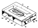
제 1 도는 본 발명의 일실시예에 따른 카세트 테이프 플레이어의 뚜껑이 덮여진 투시도.1 is a perspective view of a lid of a cassette tape player according to an embodiment of the present invention.

제 2 도는 뚜껑이 개방된 카세트 테이프 플레이어의 투시도.2 is a perspective view of a cassette tape player with the lid open.

제 3 도는 카세트 테이프 플레이어의 배면도.3 is a rear view of a cassette tape player.

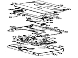
제 4 도는 카세트 테이프 플레이어의 전개도.4 is an exploded view of a cassette tape player.

제 5 도는 카세트 테이프 플레이어가 포함하고 있는 테이프 플레이어의 몸체, 카세트 홀더와 뚜껑아 상세히 도시된 투시도.5 is a perspective view showing in detail the body, cassette holder and lid of a tape player in which a cassette tape player is included.

제 6 도는 뚜껑이 잠그는 기구를 보여주기 위하여 일부를 파괴한 전면 확대 입면도.FIG. 6 is an enlarged front view of a portion destroyed to show the mechanism by which the lid is locked.

제 7 도는 내부에 있는 카세트를 보여주기 위하여 뚜껑의 일부를 절개한 카세트 테이프 플레이어의 평면도.7 is a plan view of a cassette tape player with a portion of the lid cut away to show the cassette therein.

제 8 도는 카세트 홀더에 포함된 문짝 스프링의 부착 구조의 전개도.8 is an exploded view of the attachment structure of the leaf spring included in the cassette holder.

제 9 (a)도와 제 9 (b)도는 제 7 도의 선9-9를 따른 확대된 횡단면도로서 카세트의 삽입에 따라 개방 및 폐쇄된 위치의 뚜껑을 도시한 도면.9 (a) and 9 (b) are enlarged cross sectional views along line 9-9 of FIG. 7 showing the lid in an open and closed position upon insertion of the cassette.

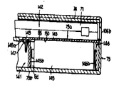
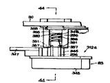
제10도는 전기 용기를 보여주기 위하여 일부를 분해한 카세트 테이프 플레이어의 투시도.10 is a perspective view of a cassette tape player with parts disassembled to show the electrical container.

제11도는 제10도의 선 11-11을 따른 확대된 횡단면도.11 is an enlarged cross sectional view along line 11-11 of FIG.

제12도는 제10도의 선 12-12에 따른 부분 횡단면도.12 is a partial cross sectional view along line 12-12 of FIG.

제13도는 헤드, 핀치 롤로와 테이프 가이드가 부착된 것을 보여주기 위하여 카세트 홀더를 확대한 투시도.Figure 13 is an enlarged perspective view of the cassette holder to show that the head, pinch rolls and tape guides are attached.

제14도는 제13도에 보이는 구조의 전면 입면도.FIG. 14 is a front elevational view of the structure shown in FIG. 13. FIG.

제15도는 헤드 부착 유니트를 지지하기 위한 구조의 확대 횡단면도.15 is an enlarged cross sectional view of a structure for supporting a head attachment unit.

제16도는 제15도의 선 16-16을 따른 자세한 단면도.FIG. 16 is a detailed cross sectional view along line 16-16 of FIG.

제17도는 헤드를 조정하기 위한 방위각을 도시한 확대된 단면도.17 is an enlarged cross sectional view showing an azimuth for adjusting the head.

제18도는 제17도의 선 18-18을 따른 단면도.FIG. 18 is a cross sectional view along line 18-18 of FIG.

제19도는 테이프 가이드의 전면 확대 입면도.19 is an enlarged front elevation view of a tape guide.

제20도는 제19도의 선 20-20을 따른 단면도.FIG. 20 is a cross sectional view along line 20-20 of FIG.

제21도는 제13도에서 보는 것의 반대편에서 본 테이프 가이드의 입면도.FIG. 21 is an elevation of the tape guide seen from the opposite side of what is seen in FIG.

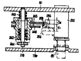
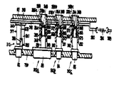
제22도는 카세트 플레이어에 포함된 테이프 구동 유니트의 단면도로서 플레이어를 뒤집어 본 상태의 도시도.Fig. 22 is a sectional view of the tape drive unit included in the cassette player, showing the player in an inverted state.

제23도는 테이프 구동 유니트의 배면도.23 is a rear view of the tape drive unit.

제24도는 제23도의 선 24-24를 따른 확대된 단면도.FIG. 24 is an enlarged cross sectional view along line 24-24 in FIG.

제25(a)도와 제25(b)도는 제24도의 테이프 구동 유니트의 전명 입면도이고, 점선은 되감기와 빨리감기 형태에서 구동유니트의 기어가 움직이는 위치를 보여주고, 실선은 정지와 재생상태에 있는 위치를 보여주는 도면.25 (a) and 25 (b) are the front elevation view of the tape drive unit of FIG. 24, and the dotted line shows the position of the gear of the drive unit moving in the form of rewind and fast forward, and the solid line is in the stop and play state. Drawing showing location.

제26(a)도와 제26(b)도는 제23도의 선 26A-26A와 26B-26B에 따른 확대 횡단면도.26 (a) and 26 (b) are enlarged cross sectional views taken along lines 26A-26A and 26B-26B of FIG.

제27(a)도와 제27(b)도는 구동 유니트에 포함된 기어의 확대 횡단면도이고, 사용되지 않을때와 상용될때를 보여주는 단면.27 (a) and 27 (b) are enlarged cross sectional views of a gear included in a drive unit, showing cross-sections when not in use and when used.

제28(a)도와 제28(b)도는 제27(a)도와 제27(b)도에서 본 기어의 배면도.28 (a) and 28 (b) are rear views of the gear as seen from the 27 (a) and 27 (b) views.

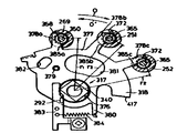
제29도는 카세트 테이프 플레이어의 재생 또는 동작 모드를 선택하기 위한 유니트의 입면도.Fig. 29 is an elevational view of a unit for selecting a playback or operation mode of a cassette tape player.

제30도는 제29도의 형태 선택 유니트에 포함된 부품이 전개된 투시도.30 is a perspective view in which parts included in the shape selection unit of FIG. 29 are deployed.

제31도는 제30도의 부품의 입면도이고, 조립된 것을 다른 면에서 본 도면.FIG. 31 is an elevational view of the component of FIG. 30 and viewed from another side;

제32(a)도에서 제32(d)도는 여러 동작 형태에 따른 제29도의 모드 선택 유니트의 FWD 레버의 동작을 보여주는 확대된 횡단면도.32 (d) to 32 (d) are enlarged cross sectional views showing the operation of the FWD lever of the mode selection unit of FIG. 29 according to various operating modes.

제33(a)도와 제33(b)도는 재생단추의 조작에 따른 제29도의 모드 선택 유니트의 FWD 레버의 동작을 보여주는 확대된 횡단면도.33 (a) and 33 (b) are enlarged cross sectional views showing the operation of the FWD lever of the mode selection unit of FIG. 29 according to the operation of the reproducing button.

제34(a)도와 제34(b)도는 FWD 레버에 의한 헤드 부착 바닥의 동작을 보여주기 위해 확대된 횡단면도.34 (a) and 34 (b) are enlarged cross sectional views to show the operation of the head attachment floor by the FWD lever.

제35(a)도와 제35(b)도는 첫번째 동작판의 FWD 레버의 동작을 보여주기 위한 관계에서 뒤집어진 단면도.35 (a) and 35 (b) are inverted cross sectional views showing the operation of the FWD lever of the first operation plate.

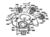
제36도의 모드 선택 유니트에 대한 안전 장치의 밑면 확대도.Bottom view of the safety device for the mode selection unit of FIG. 36. FIG.

제37도는 제36도의 선 37-37에 따른 확대된 뒤집어진 단면도.]FIG. 37 is an enlarged inverted cross sectional view along line 37-37 of FIG. 36.]

제38도는 본 말명인 카세트 테이프 플레이어에 포함된 누름단추 유니트, 잠금 유니트, 전원 스위치를 보여주는 확대된 밑면도.38 is an enlarged bottom view showing a push button unit, a locking unit, and a power switch included in the cassette tape player of the present invention.

제39도는 뒤집어진 정지단추 뭉치의 부품이 전개된 확대 입면도.FIG. 39 is an enlarged elevation view of a rolled up bundle of stop button bundles. FIG.

제40도는 조립된 정지단추의 단면도.40 is a cross-sectional view of the assembled stop button.

제41도는 제40도의 선 41-41을 따른 단면도.FIG. 41 is a cross sectional view along line 41-41 of FIG. 40;

제42도는 뒤집어진 재생단추 뭉치의 부품이 전개된 확대 입면도.42 is an enlarged elevation view in which parts of the inverted regeneration button bundle are deployed.

제43도는 조립된 재생단추의 전면도.43 is a front view of the assembled regeneration button.

제44도는 제43도의 선 44-44를 따른 단면도.FIG. 44 is a cross sectional view along line 44-44 of FIG. 43;

제45도는 뒤집어진 빨리감기 또는 FF 단추의 부품이 전개된 확대 입면도.45 is an enlarged elevation view of a flipped fast forward or FF button part deployed.

제46도는 FF 단추의 조립된 전면도.46 is an assembled front view of the FF button.

제47도는 제46도의 선 47-47에 따른 단면도.FIG. 47 is a cross sectional view along line 47-47 of FIG. 46;

제48도는 뒤집어진 잠금판과 스위치 동작판이 전개된 입면도.FIG. 48 is an elevation view of an inverted locking plate and a switch operating plate.

제 49(a)도에서 제49(c)도는 잠금 유니트의 잠금 동작과 플림동작을 설명하기 위하여 일부가 파괴된 배면도.49 (c) to 49 (c) are rear views in which part is broken to explain the locking operation and the flimping operation of the locking unit.

제50(a)도에서 제50(c)도는 잠금 유니트의 잠금과 풀림 동작을 설명하기 위한 횡단면도.50 (c) to 50 (c) is a cross-sectional view for explaining the locking and unlocking operation of the locking unit.

제51도는 뒤집어진 전원 스위치 유니트의 스위치 부착 부분의 확대된 입면도.Fig. 51 is an enlarged elevation view of the switch attachment portion of the inverted power switch unit.

제52도는 뒤집어진 전원 스위치 유니트의 전원 동작판 부분의 입명도.Fig. 52 is a drawing of the power operating plate portion of the inverted power switch unit.

제53(a)도와 제53(b)도는 전원 스위치 유니트의 동작을 설명하기 위해 일부가 파괴된 밑면도.53 (a) and 53 (b) are bottom views partially broken away to explain the operation of the power switch unit.

제54(a)도와 제54(b)도는 전원 스위치 유니트의 스위치 부착판의 동작을 설명하기 위한 측면도.54 (a) and 54 (b) are side views for explaining the operation of the switch mounting plate of the power switch unit.

제55도는 자동 재생 또는 재생 모드 제거 유니트의 일부가 파괴된 밑면도.55 is a bottom view of a portion of the automatic regeneration or the regeneration mode removal unit destroyed.

제56도는 카세트 홀더에서 잠금 이완 레버의 동작을 설명하기 위한 측면도.56 is a side view for explaining the operation of the locking release lever in the cassette holder.

제57도는 감금 이완 레버의 투시도.Fig. 57 is a perspective view of the confinement relaxation lever.

제58(a)도와 제58(b)도는 자동 재생 모드 제거 유니트에 의해 방지된는 위험을 설명하기 위한 횡단면도.58 (a) and 58 (b) are cross sectional views for explaining the risk which is prevented by the automatic regeneration mode removing unit.

* 도면의 주요부분에 대한 부호의 설명.* Explanation of symbols for the main parts of the drawings.

75: 카홀더 90 : 기구부착판75: car holder 90: instrument mounting plate

91 : 구동 유니트 98 : 홀더 몸체91: drive unit 98: holder body

본 발명은 일반적으로 자기 테이프 기록 재생 장치에 관한 것이고, 특히 테이프 카세트를 사용하는 장치들의 개선을 위한 것이다.The present invention relates generally to magnetic tape recording and reproducing apparatus, and in particular for the improvement of apparatuses using tape cassettes.

최근들어, 카세트 테이프 기록 재생 장치는 주머니에 또는 한사람이 운반할 수 있을만큼 소형화 되었다. 이러한 장치는 일반적으로 기어 뭉치를 포함한 테이프 이송가구와 캡스턴과 한싸의 릴축을 적당히 구동히기 위한 아이들러, 정상동작, 빨리감기, 도감기 모드등과 같은 장치의 선택된 또는 필요한 동작 모드를 유지시키기 위한 기어와 아이들러의 관계의 변화에 따른 모드 선택 기구를 포함하다. 전술한 비교적 복잡한 기구들이 장치의 크기를 감소화 하거나 지극히 작제 만드는 것을 어렵게 한다. 전술한 형태의 현존하는 장치들에서 최소한 몇개의 기어와 아이들러는 수평적으로 움직인다. 즉. 모드 선택 기구의 누름단추 또는 슬라이드 레버에서 주어지는 힘에 따라 장치의 샤시에 평행인 방향으로 움직인다. 모드 선택 기구의 누름단추나 슬라이드 레버는 일반적으로 장치으 평행인 방향으로 움직이게 함으로써 장치의 옆면에 누름단추를 설계하게 하는 것을 용이하게 한다. 또한 장치의 치수는 누름단추를 채택함으로써 커지게 된다.In recent years, cassette tape recording and reproducing apparatus has been miniaturized in a pocket or for one person to carry. These devices typically include gears to maintain the selected or required operating mode of the device, such as tape feeders, including gear bundles, idlers to properly drive the capstan and hansa reel shafts, normal operation, fast-forward, and rewind mode. It includes a mode selection mechanism according to the change of the idler relationship. The relatively complex mechanisms described above make it difficult to reduce the size of the device or make it extremely constructive. In existing devices of the type described above, at least some gears and idlers move horizontally. In other words. It moves in a direction parallel to the chassis of the device according to the force given by the push button or the slide lever of the mode selection mechanism. Push buttons or slide levers of the mode selection mechanism generally facilitate the design of push buttons on the sides of the device by moving them in a parallel direction. The dimensions of the device are also increased by adopting push buttons.

따라서, 본 발명의 목적은 카세트 테이프 기록 재생 장치의 크기를 최소화 하고 생산함에 있어서 간단하고 저렴한 가격을 들이는데 있다.Accordingly, an object of the present invention is to provide a simple and inexpensive price in minimizing and producing a cassette tape recording and reproducing apparatus.

좀더 나아가서, 본 발며의 목적은 카세트 테이프 기록 재생 장치의 전 치수를 거기에 사용되는 표준 소형 테이프 카세트의 치수보다 약간만 더 크게 하는데 있다.Furthermore, the purpose of the present invention is to make the entire dimension of the cassette tape recorder of reproduction only slightly larger than that of the standard small tape cassette used therein.

본 발명의 특징에 따르면 카세트 테이프 기록 재생 장치에 서로 반대편에 제 1 및 제2표면을 가진 근본적으로 직사각형인 샤시가 제공되고, 샤시의 제 1표면의 반대편에 테이프 카세트을 넣는 카세트 홀딩 수단과, 샤시의 제 1표면의 반대편에 위치한 테이프 카세트 릴에 수용하기 위하여 제 2 표면으로 부터 샤시를 관통하고 있는 릴축을 포함하는 테이프 이송 수단과, 장치의 여러 동작 모드에 따라 구동하기 위한 기어 전달 장치를 포함하고, 이러한 기어 전달 장치는 동작 모드의 변화에 따라 대응하는 축이 움직일 수 있는 기어들중 최소한 하나뿐만 아니라 샤시에 대한 모든 축들이 정산적으로 회전할 수 있게 하기 위하여 제 2 표면에 대응하는 샤시면에 있는 여러개의 기어를 포함한다. 그리고, 각각의 누름단추는 제 2 표면에 대응하는 샤시면에 위치하고 있고, 샤시의 방향으로 이완되거나 눌려진 상태에서 수동적으로 동작하며, 이완된 상태에서 누름상태로의 각 누름단추의 동작에 응답하는 수단을 포함하여 축의 방향으로 기어를 이동시킴을 나타내고 그에 따라 장치의 모드를 바꿔준다.According to a feature of the invention there is provided a cassette tape recording / reproducing apparatus provided with a substantially rectangular chassis having first and second surfaces opposite to each other, and cassette holding means for inserting a tape cassette opposite the first surface of the chassis; A tape transfer means comprising a reel shaft penetrating the chassis from the second surface for receiving in a tape cassette reel opposite the first surface, and a gear transfer device for driving in accordance with the different modes of operation of the device, Such a gear transmission is located on the chassis surface corresponding to the second surface in order to allow all axes to the chassis to rotate, as well as at least one of the gears on which the corresponding axis can move as the operating mode changes. Contains several gears. And each push button is located on the chassis surface corresponding to the second surface and is passively operated in the relaxed or depressed state in the direction of the chassis, and means for responding to the operation of each push button from the relaxed state to the depressed state. It includes moving the gear in the direction of the axis, including to change the mode of the device accordingly.

본 장치의 일실시에에 복수의 누름단추들은 장치의 동작 모드를 설정하기 위하여 선택적으로 사용할 수 있고, 샤시는 샤시 반대편에 위치하도록 같은 면에 연장된 주변을 갖게 된다. 테이프 이송가구의 모든 소자와 모든 누름단추는 카세트가 위치하고 있는 곳으로 부터 떨어진 면의 샤시 주변에 모두 수용된다.In one embodiment of the device a plurality of pushbuttons may optionally be used to set the mode of operation of the device, with the chassis having a periphery extending on the same side to be located opposite the chassis. All elements and all push buttons of the tape feeder are housed around the chassis on the side away from where the cassette is located.

본 발명에서 이상에서 말한 것과 다른 목적, 형태 잇점들은 관련된 도면과 연관해서 다음의 자세한 설명을 기술한다.DETAILED DESCRIPTION OF THE INVENTION In the present invention, the other objects and shape advantages described above are described in connection with the accompanying drawings.

본 발명의 설명은 통상의 소형 카세트(71)(이하 카세트라 함) 자기 테이트에 기록된 음향 신호만을 스테레오로 재생하기 위한 카세트 테이프 플레이어(70)에 해당되는 발명임을 나타내는 첨부 도면의 순서에 따라 자세히 기술한다.DETAILED DESCRIPTION OF THE INVENTION The present invention is described in detail in accordance with the order of the accompanying drawings showing that the invention corresponds to a cassette tape player 70 for reproducing stereo sound only recorded in a conventional small cassette 71 (hereinafter referred to as cassette) magnetic data in stereo. Describe.

제 1 도와 제 2 도에서 보듯이, 플레이어(70)는 외관 치수가 카세트(71)의 외관치수보다 약간만 크도록(불과 몇 mm) 매우 소형화된 뚜껑(74), 캐비넷트(73)로 구성된 몸체(72)를 갖는다. 케비넷트(73)의 상부(73a)는 카세트(71)가 수평적으로 그안에 수용될 수 있도록 전표명이 개방된다. 카세트 뚜껑(74)은 카세트(71)위의 캐비넷트(73)의 상부(73a)를 닫을 수 있는 구조로 되어 있다. 카세트 홀더(75)(제 1 도와 제4 도)는 카세트(71)를 수용할 수 있도록 카세트 뚜껑(74) 안쪽에 위치하고, 카세트 뚜껑(74) 안쪽에 위치하고, 카세트 뚜껑(74)이 닫히면 캐비넷트 상부(73a)안에 카세트(71)가 위치하도록 되어 있다.As shown in FIGS. 1 and 2, the player 70 has a body made of a lid 73, a cabinet 73, which is very compact so that the external dimension is only slightly larger than the external dimension of the cassette 71 (but a few mm). Has 72. The upper portion 73a of the cabinet 73 is opened so that the cassette 71 can be accommodated therein horizontally. The cassette lid 74 has a structure capable of closing the upper portion 73a of the cabinet 73 on the cassette 71. The cassette holder 75 (FIGS. 1 and 4) is located inside the cassette lid 74 to accommodate the cassette 71, located inside the cassette lid 74, and the cabinet when the cassette lid 74 is closed. The cassette 71 is located in the upper portion 73a.

몰드된 플라스틱 샤시(76)는 캐비넷트(73)안에 부착되고, 샤시(76)의 윗판(76a)은 캐비넷트 상부(73a)를 통과하여 안정된다. 윗판(76A)의 상면을 통과하면 공급릴축(77), 감는 릴축(78), 캡스턴(79)과 카세트 위치 가이드(80)가 있다(제2도)Molded plastic chassis 76 is attached to cabinet 73, and top plate 76a of chassis 76 is passed through cabinet top 73a to stabilize. Passing through the upper surface of the upper plate 76A, there is a supply reel shaft 77, a winding reel shaft 78, a capstan 79 and a cassette position guide 80 (FIG. 2).

제3도에서 보듯이, 캐비넷트(73)의 다른쪽 또는 아랫쪽에는 4개의 단추 즉, 정지단추(82), 재생(FWD)단추(83), 빨리감기(FF) 단추(84)와 되감기 단추(85)와 음량조절 손잡이(86) 등이 위치하고 있다. 누름단추(82-85)와 손잡이(86)는 각각 홈(87), (88)에 배치된다.As shown in FIG. 3, there are four buttons on the other side or the bottom of the cabinet 73: stop button 82, play (FWD) button 83, fast forward (FF) button 84 and rewind button. 85 and the volume control knob 86 is located. Push buttons 82-85 and handle 86 are disposed in grooves 87 and 88, respectively.

제 4 도를 보면, 샤시(76)의 윗판(76a)의 하면을 고정할 수 있는 금속판으로 이루어진 기구 부착판(90)있고, 기구 부착판(90)의 아랫쪽에는 테이프 구동 유니트(91)가 부착되어 있는 것을 볼 수 있다.4, there is an instrument mounting plate 90 made of a metal plate capable of fixing the lower surface of the upper plate 76a of the chassis 76, and a tape drive unit 91 is attached to the lower side of the instrument mounting plate 90. You can see it.

샤시(76)의 윗판(76a)은 캐비넷트(73)의 전면(73c)과 한면을 인접하여 바테리 삽입통로(93)로 구성되고, 바테리 삽입통로(93) 아래에 샤시(76)와 합쳐지는 바테리 수용부분(94)이 있다. 착찰식 바테리 뚜껑(95)에는 바테리 삽입통로(93)가 마련되어 있다.The upper plate 76a of the chassis 76 is composed of a battery insertion passage 93 adjacent to the front surface 73c of the cabinet 73 and joined to the chassis 76 under the battery insertion passage 93. There is a battery receiving portion 94. A battery insertion passage 93 is provided at the battery type lid 95.

제 5 도를 보면, 케비넷트(73)와 카세트 뚜껑(74)은 적당한 인조레진 또는 플라스틱 재료같은 것으로 주형된다. 카세트 홀더(75)는 박판의 금속으로 만들어진다. 카세트 홀더(75)는 캐비넷트의 윗면에 인접하여 캐비넷트(73)를 통과하여 가늘고 긴 판 형태로 된 홀더 몸체(98)를 포함하고, 홀어 몸체(98)의 반대편 끝부분에는, 홀더 몸체(98)의 아랫면을 향하여 C자 모양의 통로를 가진 카세트 홀딩 부분(99a와 99b)이 합쳐져 앞쪽으로 향하고 있다. 홀더 몸체(98) 아래에는 스테레오 재생 헤드(100), 핀치 롤로(101)와 테이프 가이드(102)가 부착되어 있다. 샤시(76)의 윗판(76a)에는 좌우 뒤 끝부분에는 한쌍의 지지부재(103a와 103b)가 있고, 조정된 한쌍의 좌우 피보트(104a와 104b)는 지지부재(103a와 103b) 안에 자리잡고 있다. 피보트(104a와 104b)는 슬리부 형태의 구멍(105a와 105b)에 대해 회전 가능하게 되어 있다.5, cabinet 73 and cassette lid 74 are molded from a suitable synthetic resin or plastic material. The cassette holder 75 is made of thin metal. The cassette holder 75 includes a holder body 98 in the form of an elongate plate passing through the cabinet 73 adjacent to the upper surface of the cabinet, and at the opposite end of the hold body 98, a holder body ( Towards the bottom of the cassette 98, the cassette holding portions 99a and 99b having the C-shaped passages are merged and faced forward. Under the holder body 98, a stereo playback head 100, a pinch roller 101 and a tape guide 102 are attached. The upper plate 76a of the chassis 76 has a pair of support members 103a and 103b at the left and right rear ends, and the adjusted pair of left and right pivots 104a and 104b are located in the support members 103a and 103b. have. The pivots 104a and 104b are rotatable with respect to the holes 105a and 105b in the form of slits.

카세트 홀더(75)는 카세트 홀딩 부분(99a와 99b)의 옆판부분(106a와 106b)에 있는 관통형 구멍(107a와 107b), 그리고 버팀 피보트(104a와 104b)를 갖고, 그에 의해 카세트 홀더(75)는 완전하게 지지된다.The cassette holder 75 has through-holes 107a and 107b in the side plate portions 106a and 106b of the cassette holding portions 99a and 99b, and the support pivots 104a and 104b, whereby the cassette holder ( 75) is fully supported.

또한 좌우 옆벽(109a와 109b)은 카세트 뚜껑(74) 위에 있고, 구멍(110a와 110b)이 있고 나사(110a와 110b)는 장저구멍(105a와 105b)안의 관통형 구멍(110a와 110b)에 삽입되고, 그에 의해 카세트 뚜껑(74)은 완전하게 지지된다. 카세트 뚜껑(74)과 카세트 홀더(75)는 같은 축에 부착된다. 돌출부(112a와 112b)는 카세트 홀더(75)의 카세트 홀딩 부분(99a와 99b)으로 부터 바깥쪽으로 연장되고, 한쌍의 단자(113a와 113b)는 카세트 뚜껑(74)의 옆벽(109a와 109b)의 안쪽 카세트 뚜껑(74)의 안쪽 표면(74a)과 단자(113a와 113b) 사이에 틈(114a와 114b)을 들 수 있도록 지지한다. 돌출부(112a와 112b)는 틈(114a와 114b)에 자리하고 그 틈 사이에서 상대적으로 움직임을 가질 수 있는 여유를 갖는다.The left and right side walls 109a and 109b are also on the cassette lid 74, with holes 110a and 110b and screws 110a and 110b inserted into the through holes 110a and 110b in the bottom holes 105a and 105b. The cassette lid 74 is thereby fully supported. The cassette lid 74 and cassette holder 75 are attached to the same shaft. The protrusions 112a and 112b extend outward from the cassette holding portions 99a and 99b of the cassette holder 75, and the pair of terminals 113a and 113b extend the side walls 109a and 109b of the cassette lid 74. A gap 114a and 114b is supported between the inner surface 74a of the inner cassette lid 74 and the terminals 113a and 113b. The protrusions 112a and 112b are located in the gaps 114a and 114b and have a margin to move relatively between the gaps.

결과적으로 카세트 뚜껑(74)은 카세트 홀더(75)에 대해 상대적으로 미리 정해진 각 범위θ1(제9(a)도) 내에서 움직일 수 있게 하는 카세트 홀더(75)를 포함한다. 한 지지부재(103a)에는 카세트 홀딩 부분(99a)의 옆판부분(106a)의 두개의 서로 떨어진 구멍 각각 들어가는 코일형 스프링에 의해 압압되는 공같은 제륜자 또는 역회전 방지 기구가 있고(보이진 않음), 그에 따라 카세트 홀더(75)는 카세트 삽입 위치(제9(a)도) 또는 카세트 장진 위치(제9(b)도)에 선택적으로 유지된다. 샤시(76)의 앞멱(115)의 안쪽에 스프링으로 구성된 한쌍의 카세트 압착기(116a 116b)가 부착되어 있다.As a result, the cassette lid 74 includes a cassette holder 75 which allows movement within a predetermined angular range θ 1 (figure 9 (a)) relative to the cassette holder 75. One support member 103a has a ball-wheeled wheelbarrow or a reverse rotation prevention mechanism (not shown) which is pressed by coiled springs which enter each of two mutually spaced holes of the side plate portion 106a of the cassette holding portion 99a, Thus, the cassette holder 75 is selectively held at the cassette insertion position (Fig. 9 (a)) or the cassette long position (Fig. 9 (b)). A pair of cassette presses 116a and 116b made of a spring is attached to the inside of the front side 115 of the chassis 76.

제 5 도에 처럼, 일반적으로 ㄴ자 형태의 지지대(119)는 카세트 뚜껑(74)의 앞 가장자리 또는 테드리으 안쪽에 있다. 반면에 제 6 도에서 보면 캐비넷트(73)의 앞벽(115)의 위 끝부분에 지지대(119)의 사용에 따라 카세트 뚜껑(74)을 잠그기 위하여 잠금 또는 걸쇠기구(120)가 부착되어 있다. 잠금기구(120)는 샤시(76)의 앞벽(115)의 적당히 마련된 구석에 움직일 수 있는 잠금판(121)을 포함하고, 캐비넷트(73)의 앞벽(73c)의 구석에 있게 된다. 잠금판(121)의 위 끝에는 위 끝부분에 경사면(122)을 갖는 잠금톱니 멈춤쇠(123)가 있고 잠금판(121)의 아래부분에는 앞벽(73c)의 절단면을 통과하여 노출되는 손잡이부분(124)이 있다. (제 1 도).As shown in FIG. 5, generally the B-shaped support 119 is inside the front edge of the cassette lid 74 or inside Tedrie. On the other hand, in FIG. 6, the locking or latching mechanism 120 is attached to the upper end of the front wall 115 of the cabinet 73 to lock the cassette lid 74 according to the use of the support 119. The locking mechanism 120 includes a locking plate 121 that is movable in a properly provided corner of the front wall 115 of the chassis 76 and is in the corner of the front wall 73c of the cabinet 73. The upper end of the locking plate 121 has a locking tooth detent 123 having an inclined surface 122 at an upper end thereof, and a handle portion exposed through the cutting surface of the front wall 73c at the lower portion of the locking plate 121 ( 124). (Figure 1).

또한 홈(125)은 잠금판(121)의 뒤편에 있고, 억압 스프링(126)은 벽(115)으로 부터 홈(125)으로 통과하는 단자(127)의 반대편에 인접한 홈(125)안에 수용되고 스프링(126)의 다른끝은 점선부분(128)에서 처럼(제 6 도)홈(125)의 끝에 반대편에 인접한다. 결과적으로 잠금판(121)은 억압 스프링(126)에 의하여 제 6 도의 오른쪽으로 밀리게 된다.The groove 125 is also behind the locking plate 121 and the suppression spring 126 is received in the groove 125 adjacent to the opposite side of the terminal 127 passing from the wall 115 to the groove 125. The other end of the spring 126 is adjacent to the opposite end of the groove 125 as in dotted line 128 (FIG. 6). As a result, the locking plate 121 is pushed to the right in FIG. 6 by the suppression spring 126.

제 5 도, 제7 도와 제 9 (b)도를 보면 한쌍의 좌우 박편 스프링(130a와 130b)이 카세트 뚜껑(74)과 카세트 홀더(75)사이에 위치한다. 제 8 도에서 스프링(30b)에 대하여 살펴보면 박편 스프링(130a와 130b) 의 각 끝부분은 일반적으로 포크 모양의 세개의 스프링가지 또는 편심부분이 있고, 바깥가지 또는 스프링 편심부분은 위를 향하고 있으며 반면에 가운데가지 또는 스프링 편심부분(131b)은 아래를 향하고 있다.5, 7 and 9 (b), a pair of left and right lamella springs 130a and 130b are positioned between the cassette lid 74 and the cassette holder 75. As shown in FIG. Referring to the spring 30b in FIG. 8, each end of the lamella springs 130a and 130b generally has three fork-shaped spring branches or eccentrics, while the outer branches or spring eccentrics face upwards. The middle branch or spring eccentric portion 131b is directed downward.

또한 가운데구멍(133)은 각각의 스프링(130a와 130b)의 밑부분(132)에 있고, 밑부분(132)과 끝부분 사이에는 구부러진 부분 또는 약간 오른쪽 아래로 구부러진 꼬리표(134)와 마주치게 된다. 가늘과 긴 구멍(135a와 135b)은 카세트 홀더(75)의 카세트 홀딘 부분(99a와 99b)의 꼭대기에 있다. 박편 스프링(130a와 130b)은 가늘고 긴 구멍(135a와 135b)의 끝반대편의 꼬리표(134)에 위치하고, 홀더 몸체(98)의 카세트 홀딘 부분(99a와 99b)의 윗표면에 도드라진 은못(136a와 136b)을 수용하는 대응구멍(133)이 있다. 은못(136a와 136b)의 머리는 박편 스프링(130a와 130b)이 카세트 홀더(75)에 대해 안전하도록 툭 튀어나와 있거나 뭉뚝하게 되어 있다.In addition, the central hole 133 is located at the bottom 132 of each of the springs 130a and 130b, and encounters a bent portion or a slightly curved right side tag 134 between the bottom 132 and the end. . The slits and long holes 135a and 135b are at the top of the cassette holdin portions 99a and 99b of the cassette holder 75. The lamella springs 130a and 130b are located on the tag 134 opposite the end of the elongated holes 135a and 135b, and the dowel 136a raised on the upper surface of the cassette holdin portions 99a and 99b of the holder body 98 is shown. And a corresponding hole 133 for receiving 136b. The heads of the dowels 136a and 136b are protruding or blunt to allow the flake springs 130a and 130b to be secured against the cassette holder 75.

카세트 홀더(75)에 대해 안전한 각각의 스프링(130a와 130b)의 중앙 스피링 편심 부분(131b)은 가늘고 긴 구멍(135a와 135b)중 하나에 삽입된다. 물론, 박편 스프링(130a와 130b)은 카세트 홀더(75)대신 카세트 뚜껑(74)에 고정될 수도 있다. 플레이어(70)로의 카세트 장진은 제9(a)도와 제9(b)도에서 설명될 것이다.The central spring eccentric portion 131b of each of the springs 130a and 130b secured to the cassette holder 75 is inserted into one of the elongated holes 135a and 135b. Of course, the lamella springs 130a and 130b may be fixed to the cassette lid 74 instead of the cassette holder 75. The cassette loading into the player 70 will be explained in the ninth (a) and ninth (b) diagrams.

제 9 (a)도에서 보면, 카세트 뚜껑(74)이 첫번으로 열리면, 카세트 홀더(75)은 샤시(76)의 윗판(76a)에 대해 약 45°기울어진 각도를 위치한다. 카세트 뚜껑(74)은 카세트 홀더(75)에 대해 θ1은 돌추리부(112a와 112b)에 따른 단자(113a와 13b)의 인접치에 의해 결정된다.In FIG. 9 (a), when the cassette lid 74 is first opened, the cassette holder 75 is positioned at an angle of about 45 ° with respect to the top plate 76a of the chassis 76. The cassette lid 74 is for θ 1 to the cassette holder 75 is determined by the adjacent teeth of the terminal (113a and 13b) of the stone reasoning unit (112a and 112b).

박편 스프링(130a와 130b)의 중앙 스프링 편심부분(131b)은 가늘고 긴 구멍(135a와 135b) 안에 위치하고, 이는 홀더 몸체(98)의 박편 금속 재료의 두께내에 있음을 나타내고, 그럼으로써 홀딩 부분(99a와 99b)의 안쪽 아래로 돌출하지 않게 된다.The central spring eccentric portion 131b of the flake springs 130a and 130b is located in the elongated holes 135a and 135b, indicating that it is within the thickness of the flake metal material of the holder body 98, thereby holding part 99a. And 99b) do not protrude below the inside.

뚜껑(74)이 열려진 상태에서, 표준 카세트(71)는 앞쪽부터 열려진 면(137)에서 카세트 홀더(75) 안으로 비스듬하게 아래쪽으로 삽입되고 카세트(71)의 반대쪽 끝부분이 미끄러져 수용되면 카세트 홀딩 부분(99a와 99b)에 유지되게 된다(제 7 도). 카세트를 삽입하는 동안, 카세트 뚜껑(74)은 카세트 홀더(75)에 대해 θ1만큼 열려져 있으므로, 카세트 뚜껑의 존재는 카세트의 삽입을 방해하지 않고, 지극히 쉽게 이루어진다. 또한, 박편 스프링(130a와 130b)의 중앙 스프링 편심 부분(131b)은 홀더 몸체(98)에서 아래쪽으로 돌출되지 않고, 삽입되고 있는 카세트(71)는 이 스프링 편심부분(131b)에 절대로 걸리지 않는다.With the lid 74 open, the standard cassette 71 is inserted obliquely downward into the cassette holder 75 on the open side 137 from the front and the cassette holding when the opposite end of the cassette 71 slides in and is received. It is held in portions 99a and 99b (Fig. 7). While inserting the cassette, the cassette lid 74 is opened by θ 1 with respect to the cassette holder 75, so that the presence of the cassette lid does not interfere with the insertion of the cassette and is made extremely easy. Further, the central spring eccentric portion 131b of the flake springs 130a and 130b does not protrude downward from the holder body 98, and the cassette 71 being inserted is never caught by this spring eccentric portion 131b.

앞에 언급한 카세트 삽입이 끝나면, 카세트 뚜껑(74)은 카세트(71)의 장진을 완료하기 위하여 제 9(a)도의 화살표 a'방향으로 이동하게 된다. 이 경우, 각각의 박편 스프링(130a와 130b)의 스프링 편심부분(131a)은 화살표a'방향으로 뚜껑(74)을 이동시키기 위하여 카세트 홀더(75)를 미는 카세트 뚜껑(74)의 안쪽 표면(74a)에의해 눌려지고, 동시에 박편 스프링(130a와 130b)의 중앙 스프링 편심부분(131b)은 홀더 몸체(98)의 구멍(135a와 135b)을 통해 아래쪽으로 돌출되고, 카세트(71)의 위표면에 기대어 지탱하게 된다. 카세트 뚜껑(74)이 완전히 닫히면, 제9(b)도의 실선이 나타내는 것처럼, 카세트(71)는 릴축(77, 78)과 캡스턴(79)과 카세트 위치 가이드(80) 위에 고정되고, 샤시(76)의 윗판(76a)위에 수평으로 장진되게 한다. 동시에, 카세트 누름 스프링(116a와 116b)은 카세트 홀더(75)안의 뒤쪽을 카세트를 누르기 위하여 카세트(71)를 누르게 되고, 따라서 카세트는 앞뒤 방향으로 안전하게 위치하게 된다. 그후, 뚜껑 닫힘이 완료되면, 카세트 뚜껑(74)의 지지대(119)는 잠금기구(120)에 의해 잠기게 된다. 더 나아가서, 카세트 뚜껑(74)이 완전히 닫히기 직전에 잠금 톱니 멈춤쇠(123)의 구부러진 면(122)은 지지대(119)에 의해 동작하고 따라서 자금판(121)은 스프링(126)의 편심을 향해 제 6 도의 왼쪽으로 이동하고, 지지대(119)가 있는 잠금톱니 멈춤쇠(123)를 받아들이기 위하여 이 스프링에 의해 오른쪽으로 되돌아오고, 그에 의해 정위치에 카세트 뚜껑(74)을 잠그게 된다. 카세트 뚜껑(74)이 잠기면, 카세트 홀더(75)는 박편 스프링(130a와 130b)의 중앙 스프링 편심부분(131b)는 샤시(76)의 위판(76a)을 향해 밀리게 되고, 반대로 박편 스프링(130a와 130b)의 중앙 스프링 편심부분(131b)는 샤시(76)의 윗판(76a)을 향해 밀리게 되고, 반대로 박편 스프링(130a와 130b)의 중앙 스프링 편심부분(131b)는 샤시(76)의 위판(76a)을 향해 민다.When the aforementioned cassette insertion is completed, the cassette lid 74 is moved in the direction of arrow a 'of FIG. 9 (a) to complete the loading of the cassette 71. FIG. In this case, the spring eccentric portion 131a of each of the lamella springs 130a and 130b has an inner surface 74a of the cassette lid 74 that pushes the cassette holder 75 to move the lid 74 in the direction of arrow a '. ), And at the same time the central spring eccentric portion 131b of the lamella springs 130a and 130b protrudes downward through the holes 135a and 135b of the holder body 98 and on the upper surface of the cassette 71. Leaning against it. When the cassette lid 74 is completely closed, the cassette 71 is fixed on the reel shafts 77 and 78, the capstan 79 and the cassette position guide 80, as shown by the solid line in FIG. 9 (b), and the chassis 76 On the top plate (76a) horizontally. At the same time, the cassette pressing springs 116a and 116b press the cassette 71 to press the cassette back into the cassette holder 75, so that the cassette is safely positioned in the front and rear directions. Then, when the lid is closed, the support 119 of the cassette lid 74 is locked by the locking mechanism 120. Furthermore, the bent face 122 of the locking tooth detent 123 is operated by the support 119 just before the cassette lid 74 is fully closed and thus the plate plate 121 is directed towards the eccentricity of the spring 126. Moving to the left of FIG. 6, it is returned to the right by this spring to receive the lock tooth detent 123 with the support 119, thereby locking the cassette lid 74 in place. When the cassette lid 74 is locked, the cassette holder 75 pushes the center spring eccentric portion 131b of the lamella springs 130a and 130b toward the upper plate 76a of the chassis 76 and, conversely, the lamella spring 130a. And central spring eccentric portion 131b of 130b are pushed toward top plate 76a of chassis 76, whereas central spring eccentric portion 131b of flake springs 130a and 130b is upper plate of chassis 76. Push toward 76a.

카세트 장진이 완료되면, 카세트(71)안으로 재생헤드(100)를 삽입하고, 테이프 접촉시키기 위하여 재생 단추(83)를 누르면, 동시에 테이프를 통해 캡스턴(79)에 핀치 롤러(101)접촉시키기 위해 누르는 동작이 일어나고, 그에 따라 이후에 자세히 기술하게 될 플레이어(70)의 스테레오 재생 모드가 완료된다. 플레이어(70)로 부터 카세트(71)를 빼기 위하여서는, 억압 스프링(126)의 편심방향으로 제 6 도의 왼쪽에 있는 잠금판(121)의 손잡이부분(124)을 살짝 누르면, 그에 따라 잠금톱니 멈춤쇠(123)는 지지대(119)로 부터 풀려지고, 카세트 뚜껑(74)은 박편 스프링(130a와 13b)의 스프링 편심부분(131a0의 반발하는 힘에 의하여 제9(b)도의 선에 나타낸 위치로 불쑥 튀어오르고, 이는 사용자에게 카세트 뚜껑(74)이 열릴 준비가 완료되었음을 나타나게 된다. 뚜껑(74)이 불쑥 튀어오른후, 카세트 뚜껑(74)의 앞끝 또는 테두리(118) 아래 쉽게 손가락끝을 걸 수 있고, 카세트 뚜껑(74)는 제9(a)도에 보이는 열려진 위치로 쉽게 이동할 수 있게 된다.When cassette loading is completed, insert the playhead 100 into the cassette 71, press the play button 83 to make tape contact, and press to contact the pinch roller 101 to the capstan 79 through the tape at the same time. The operation takes place, thus completing the stereo playback mode of the player 70 which will be described in detail later. To remove the cassette 71 from the player 70, press the handle 124 of the locking plate 121 on the left side of FIG. 6 in the eccentric direction of the suppression spring 126 to stop the locking teeth accordingly. The iron 123 is released from the support 119, and the cassette lid 74 is moved to the position shown in the line of Fig. 9 (b) by the repulsive force of the spring eccentric portion 131a0 of the flake springs 130a and 13b. It pops up, which indicates to the user that the cassette lid 74 is ready to open After the lid 74 pops up, the fingertip can be easily hung under the front end or border 118 of the cassette lid 74. And the cassette lid 74 can be easily moved to the opened position shown in FIG. 9 (a).

카세트 뚜껑(74)이 완전히 열려지면, 회전 멈춤 기구에 의해 다시 제위치로 돌아옴으로써 카세트 홀더(75)는 제 9a와 같은 카세트 삽입 위치로 튀어올라와 돌출부(112a와 112b)는 단자(113a 와 113b)에 의해 수용된다. 그후 카세트(71)는카세트 홀더(75)안에서 비스듬히 위방향으로 인출되고 이 인출은 카세트를 삽입할때와 마찬가지로 지극히 쉽고 부드럽게 이루어진다.When the cassette lid 74 is fully opened, the cassette holder 75 springs back to the cassette insertion position such as the ninth a by returning to the position again by the rotation stop mechanism, and the protrusions 112a and 112b are connected to the terminals 113a and 113b. Is accepted by. The cassette 71 is then drawn out obliquely upwards in the cassette holder 75 and this withdrawal is extremely easy and smooth as with inserting the cassette.

제10도 내지 제12도에 관해서 보면, 바테리 수용 유니트(141)는 앞에 언급한 바테리 삽입 통로(93), 캐비넷트(73)의 바테리 수용 부분(94), 바테리 뚜껑(95)으로 이루어져 있고, 샤시(76)의 윗판(76a) 위에 장진되는 카세트(71)를 위한 카세트 수용부분(142)에 바로 인접한 아래에 있게 됨을 알 수 있다. 바테리 수용부분(94)안에 UM-3 바테리 같은 두개의 바테리를 넣게 되면, 이들은 평행으로 위치한다.10 to 12, the battery accommodating unit 141 is composed of the aforementioned battery insertion passage 93, the battery accommodating portion 94 of the cabinet 73, and the battery lid 95, It can be seen that it is directly below the cassette receiving portion 142 for the cassette 71 which is mounted on the top plate 76a of the chassis 76. If two batteries, such as UM-3 batteries, are placed in the battery receiving portion 94, they are placed in parallel.

바테리 수용부분(94)에 삽입된 바테리(143)는 바테리 수용부분(94)의 바닥인 샤시(76)에 부착된 바테리 받침(144)의 반대쪽을 따라 자리잡게 된다. 또한, 바테리 수용부분(94)안에 삽입된 바테리(143)는 바테리 수용부분(94) 안쪽의 반대끝쪽 부착된 단자부속(145a와 145b)에 압압 접촉되는 그들 자체의 극을 갖고, 그에 의해 전원 공급 회로에 연결된다. 바테리 뚜껑(95)은 적당한 인조레진 또는 플라스틱 재료로 주형되고, 한 쪽 끝에는 한쌍의 지지단자(146)가 마련되어 있고, 뚜껑(95)의 다른 끝에는 거기에 부착되는 일반적으로 U자 형태의 탄력있는 걸쇠(147)를 갖는다.The battery 143 inserted into the battery receiving portion 94 is positioned along the opposite side of the battery support 144 attached to the chassis 76 which is the bottom of the battery receiving portion 94. In addition, the batteries 143 inserted into the battery receiving portion 94 have their own poles which are in pressure contact with the terminal parts 145a and 145b attached to opposite ends inside the battery receiving portion 94, thereby supplying power. Connected to the circuit. The battery lid 95 is molded from a suitable synthetic resin or plastic material, and is provided with a pair of support terminals 146 at one end and a generally U-shaped resilient clasp attached thereto at the other end of the lid 95. Has 147.

바테리 수용부분(94) 안으로 바테리(143)의 삽입이 끝나면, 바테리 삽입통로를 닫기 위하여 바테리 통로(93)안으로 바테리 뚜껑(95)을 안전하게 옮길 수 있다. 이때, 바테리 뚜껑(95)의 한쪽끝은 샤시(76)에 부착된 한쌍의 지지구멍(148)에 있는 지지단자(146)를 통해 수용되고(제10도), 다른한쪽 끝에서는 걸쇠(147)가 샤시(76)의 윗판(76a)에 부착된 지지구멍(149)안으로 탄력성을 이용하여 삽입되고 지지구멍(149)의 한쪽 끝(149a)에 수용된다(제12도).When the insertion of the battery 143 into the battery receiving portion 94 is completed, the battery lid 95 may be safely moved into the battery passage 93 to close the battery insertion passage. At this time, one end of the battery lid 95 is received through the support terminal 146 in the pair of support holes 148 attached to the chassis 76 (FIG. 10), and the latch 147 at the other end. Is inserted into the support hole 149 attached to the upper plate 76a of the chassis 76 with elasticity and received at one end 149a of the support hole 149 (FIG. 12).

결과적으로, 바테리 뚜껑(95)은 윗판(76a)과 같은 높이로 부착된다. 바테리 수용부분(94)의 높이 h1을 최소화 하기 위하여, 그에 따라 카세트 테이프 플레이어(70)의 두께가 최소화됨으로 바테리 외경과 일치하는 구부러진 움푹한 곳(150)은 두께 h1에 대응하는 뚜껑(95)의 실효 두께 h2가 매우 작아지게 됨으로 바테리 뚜껑(95)의 안쪽 표면에 만들어진다. 바테리 수용 유니트(141)에서, 바테리 뚜껑(95)은 캐비넷트(73)의 외부 표면에 직접 노출되지 않는다. 결과적으로 바테리 뚜껑(95)이 대단히 얇게 만들어져 있을지라도, 강도에는 아무 문제가 없다. 또한, 바테리 뚜겅(95)은 캐비넷트(73)의 외부 표면에 절대로 노출되지 않으므로, 플레이어 외부장식의 설계를 하는데 많은 하는데 많은 여유가 있다.As a result, the battery lid 95 is attached at the same height as the top plate 76a. In order to minimize the height h 1 of the battery accommodating portion 94, the thickness of the cassette tape player 70 is thus minimized so that the bent recess 150 corresponding to the battery outer diameter 150 has a lid 95 corresponding to the thickness h 1 . The effective thickness h 2 of) becomes very small, which is made on the inner surface of the battery lid 95. In the battery receiving unit 141, the battery lid 95 is not directly exposed to the outer surface of the cabinet 73. As a result, even if the battery lid 95 is made very thin, there is no problem in strength. In addition, since the battery cover 95 is never exposed to the outer surface of the cabinet 73, there is a lot of room for designing the player exterior.

카세트 홀더(75)안에는 홀더 부착 유니트(153)(제13도 내지 15도), 헤드 방위각 조정 유니트(154)(제17도, 내지 제18도), 테이프 가이드 유니트(155)(제19도 내지 21도)가 부착된다.In the cassette holder 75, a holder attachment unit 153 (FIGS. 13 to 15 degrees), a head azimuth adjustment unit 154 (FIGS. 17 to 18), and a tape guide unit 155 (FIGS. 19 to 19) 21 degrees) is attached.

제13도와 제14도를 보면, 지지축(157)은 카세트 홀더(75)의 홀더 몸체(98)의 한쪽 끝부분에 고정되고, 지지축(157)의 아래끝에는 헤드저부(158)의 한끝에 부착된다. 재생 헤드(100)는 헤드저부(158)의 자유로운 한끝(158a)에 인접한 헤드저부(158)에 방위각 조정 유니트(154)를 통해 부착된다. 또한, 홀더 몸체(98)와 헤드저부(158) 사이에, 또, 축(157)과 재생 헤드(100)사이에 횡단면이 일반적으로 C형태를 가진 핀티 롤로 지지레버(159)가 위치하고 지지축(157)의 한끝에 부착된다. 핀치 롤로 지지레버(159)의 자유로운 끝(159a)은 회전하는 핀치 롤러(101)가 부착되는 지지축(160)으로 움직인다. 핀치 롤로(101)로 부터 떨어진 홀더 몸체(98)의 끝부분에는 높이 조정 유니트(161)를 통해 테이프 가이드(102)가 부착된다. 사이에 위치하는 재생 헤드(100)의 상대적인 테이프 주행 방향으로 보면, 핀치 롤러(101)는 아래쪽에 자리잡고 테이프 가이드(102)는 위쩍에 자리잡는다. 대생 헤드(100)와 테이프 가이드(102) 사이의 홀더 몸체(98)의 아래쪽에는 차폐판(162)이 부착된다. 헤드저부(158)는 축(157)에 까지 뻗힌 비틀림 스프링(163)을 통해 제13도의 화살표 b방향으로 밀리고, 그끝은 홀더 몸체(98)와 헤드저부(158)에 정착한다. 헤드저부(158)의 자유로운 끝(158a)이나 단부는 화살표 b방향으로 헤드저부(158)의 수직 이동을 제한하는 차폐판(162)의 낮은쪽 끝에 있는 멈춤기(164)에 결합된다.13 and 14, the support shaft 157 is fixed to one end of the holder body 98 of the cassette holder 75, and the lower end of the support shaft 157 is connected to one end of the head bottom 158. Attached. The reproduction head 100 is attached via the azimuth adjustment unit 154 to the head bottom 158 adjacent to the free end 158a of the head bottom 158. In addition, between the holder body 98 and the head bottom 158, and between the shaft 157 and the regeneration head 100, the support lever 159 is positioned with a pinty roll having a generally C shape, and the support shaft ( 157) is attached to one end. The free end 159a of the support lever 159 with the pinch roll moves to the support shaft 160 to which the rotating pinch roller 101 is attached. The tape guide 102 is attached to the end of the holder body 98 away from the pinch roll 101 through the height adjustment unit 161. When viewed in the relative tape travel direction of the reproducing head 100 located between, the pinch roller 101 is located at the bottom and the tape guide 102 is located at the top. A shield plate 162 is attached to the lower side of the holder body 98 between the college head 100 and the tape guide 102. The head bottom 158 is pushed in the direction of arrow b in FIG. 13 through the torsion spring 163 extending up to the shaft 157, the end of which is fixed to the holder body 98 and the head bottom 158. The free end 158a or end of the head bottom 158 is coupled to the stop 164 at the lower end of the shield plate 162 which limits the vertical movement of the head bottom 158 in the direction of arrow b.

핀치 롤러 지지축(160)의 낮은쪽 끝은 레버(159) 아래까지 뻗치고 헤드저부(159) 안의 구멍(165)에 헐겁게 삽입된다. 구멍(164)안의 지지축(160)의 이동범위는 헤드저부(158)에 대한 핀치 롤러 레버(159)의 가능한 수직 이동을 한정한다.The lower end of the pinch roller support shaft 160 extends below the lever 159 and is loosely inserted into the hole 165 in the head bottom 159. The range of movement of the support shaft 160 in the hole 164 defines the possible vertical movement of the pinch roller lever 159 relative to the head bottom 158.

핀치 롤러 레버(159)의 자유로은 끝(159a)이나 단부와 방위각 조정 유니트(154)의 스프링 고리(166) 사이에는 헤드저부(158)에서 볼때 제13도의 화살표 b'의 방향으로 핀치 롤로 레버(159)를 밀기 위하여 장력 스프링(167)이 있다.Between the free end 159a or the end of the pinch roller lever 159 and the spring ring 166 of the azimuth adjustment unit 154, the lever 159 with the pinch roll in the direction of arrow b 'in FIG. 13 when viewed from the head bottom 158 There is a tension spring 167 to push.

헤드 부착 유니트(153)는 축(157), 헤드저부(158)와 비틀림 스프링(163)으로 구성된다. 이 유니트에서 축(157)의 위 끝(157a)은 뾰족한 징이나 갈고리에 의해 홀더 몸체(98)에 고정된다. 헤드저부(158)의 축끝은 아래에서 부터 축(157)위에 부착된 슬리브(169)의 아래끝(169a)에 부착되고, 그에 의해 수직으로 고정된다. 슬리브(169)는 축(157)의 아래끝(157b)의 주위에 부착된 E링(170)에 의해 축(157)으로 부터 아래쪽으로 움직이는 것이 방지된다. 원통형의 위 아래 핀치 롤러 레버 베어린 부분(171a와 171b)은 축(157)과 슬리브(169)로 구성된다. 위 아래 관통형 구멍(173a와 173b)은 핀치 롤러레버(159)의 위 아래쪽(172a와 172b)의 끝부분에 있고 이 구먼(173a와 173b)은 핀치 롤러 베어링부분(171a와 171b)을 받아들인다. 슬리브(169)의 위 끝(169b)와 위 핀치 롤러 베어링(171a) 사이에는 틈(174)이 있고(제15도), 슬리브(169)는 틈(174)의 범위내에서 축(157)의 바깥 주변에서 위아래로 움직인다. 슬리브(160)의 이 수직운동에 의하여, 헤드저부(158)는 제15도에 보이는 높이 h3의 범위내에서 함께 움직인다. 비틀림 스프링(163)은 슬리브(169) 주위에 감겨진 코일 부분(163c)과 홀더 몸체(98)에 있는 지지구멍(175a와 175b)에 걸리는 위 아래 끝부분(163a, 163b)과 헤드저부를 포함한다.The head attachment unit 153 is composed of a shaft 157, a head bottom 158 and a torsion spring 163. In this unit, the upper end 157a of the shaft 157 is fixed to the holder body 98 by a sharp gripping or hook. The shaft end of the head bottom 158 is attached to the bottom end 169a of the sleeve 169 attached from above to the shaft 157 and thereby fixed vertically. The sleeve 169 is prevented from moving downward from the shaft 157 by an E ring 170 attached around the lower end 157b of the shaft 157. The cylindrical up and down pinch roller lever barelin portions 171a and 171b consist of a shaft 157 and a sleeve 169. Top and bottom through holes 173a and 173b are at the ends of the top and bottom 172a and 172b of the pinch roller lever 159, and these holes 173a and 173b receive the pinch roller bearing portions 171a and 171b. . There is a gap 174 between the upper end 169b of the sleeve 169 and the upper pinch roller bearing 171a (FIG. 15), and the sleeve 169 is in the range of the gap 174 of the shaft 157. Move up and down around the outside. By this vertical movement of the sleeve 160, the head bottoms 158 move together in the range of height h 3 shown in FIG. Torsion spring 163 includes a coil portion 163c wound around sleeve 169 and upper and lower ends 163a, 163b and head bottom that engage the support holes 175a and 175b in holder body 98. do.

핀치 롤러 지지레버(159) 부분에 비틀림 스프링(163)의 아래끝 부분(163b)을 통과하는 연장부에 이탈 노치(176)가 있다. 비틀림 스프링(163)의 코일 부분(163c)은 장착되면 비틀려 힘을 받고, 수직으로 압축된다. 코일부분(163c)이 비틀려 힘을 받음으로써, 헤드저부(158)는 제15도의 화살표 C의 방향으로 밀린다. 또한 제14도에서 보는것처럼 부착한(90)의 위 표면에는 헤드저부(158) 아래 위치하는 여러개의 돌출부(177)가 있다.A part of the pinch roller support lever 159 has a release notch 176 at an extension portion passing through the lower end portion 163b of the torsion spring 163. The coil portion 163c of the torsion spring 163 is twisted when mounted and is compressed vertically. As the coil portion 163c is twisted and subjected to a force, the head bottom 158 is pushed in the direction of arrow C in FIG. In addition, as shown in FIG. 14, the upper surface of the attachment 90 has several protrusions 177 located below the head bottom 158.

위에서 처럼 구성한 헤드 부착 유니트(153)에서, 카세트(71)가 카세트 홀더에 삽입된 후 카세트 홀더의 아래로의 수직 운동에 의해 샤시(76)의 위판(76a) 위에 수평으로 장진되면 제14도에서 처럼 헤드저부(158)는 비틀림 스프링(163)의 코일부분(163c)의 억압하는 힘에 의해 부착판(90)위의 돌출부(177)에 누름 접점안에 탄력성 있게 접초되고, 헤드저부(158)의 높이는 카세트(71)에서 테이프에 대한 재생 헤드(100)의 높이로 정확히 결정된다. 헤드저부(158)가 축(157)에 수직으로 부착됨으로써 구조상 약간의 헐거움은 피할 수 없다. 아무리 작은 헐거움이러도 재생헤드(100)의 높이에 편이를 가져오게 됨으로써 특히 헤드(100)가 스테레오를 재생할때 트레킹 오차를 가져온다.In the head attachment unit 153 configured as above, the cassette 71 is inserted into the cassette holder and then loaded horizontally over the top plate 76a of the chassis 76 by the vertical movement of the cassette holder downward in FIG. As such, the head bottom 158 is elastically contacted in the pressing contact with the protrusion 177 on the attachment plate 90 by the pressing force of the coil portion 163c of the torsion spring 163, and the head bottom 158 The height is accurately determined by the height of the playback head 100 relative to the tape in the cassette 71. As the head bottom 158 is attached perpendicular to the shaft 157, some looseness in construction is inevitable. Even the smallest looseness brings a shift in the height of the playhead 100, which results in a tracking error, especially when the head 100 plays stereo.

위에 언급한 헤드 부착 유니트(153)에서 헤드저부(158)의 높이는 축(157)의 헤드저부(158)의 수직적인 헐거움에 관계없이 미리 정확하게 결정되었기 때문에 트레킹 오차는 전혀 나타나지 않는다. 위에 말한대로 플레이어(70)에 카세트가 장진되고 재생단추(83)가 늘려지면, 헤드저부(158)는 높이 제한 돌출부(177) 위로 미끄러지는동안 스프링(163)의 비틀림 저항에 따라 제13도의 화살표 b방향으로 자리잡게 된다. 방위각 조정 유니트(154)가 스포트 용접과 같은 것에 의해 긴 헤드 부착판(179)이 나사(180)에 의해 헤드저부(158)에 한 끝(179a)으로 고정되면, 헤드 부착판(179)을 따라 대략중간에 위치하도록 고정된 재생헤드(100)는 제17도와 18도는 설명에서 기술된다. 헤드 부착판(179)을 따라 대략중간에 위치하도록 고정된 재생헤드(100)는 제17도와 18도는 설명에서 기술된다. 헤드 부착판(179)이 나사 (180)에 의해 헤드저부(158)에 한 끝(179a)으로 고정되면, 헤드부착판(179)의 다른 끝(179b)은 그 안에 세로의 구멍(181)을 갖는다. 방위각 조정 나사(182)는 여기서 부터 구멍(181) 통하여 연장되고 헤드저부(158)에 있는 가느다란 구멍에서 잠겨진다. 박편 스프링(184)과 공간자(185)는 헤드 부착판(179)의 끝부분(179a)과 헤드저부(158) 사이에 위치하고 나사(180)에 의하여 그 위치에 고정된다. 박편 스프링(184)은 일반적으로 V자 형태를 각조 헤드부착한(179)의 아래 표면을 향해 자유로운 끝(184b)에 탄력성있게 수용되게 하기 위해 구부러진 스프링 편심부분(184a)을 포함한다. 스프링 편심부분(184a)의 정점부분(184c)은 헤드저부(158)에 있는 긴 구멍(186)에 들어가게 된다(제17도).Since the height of the head bottom 158 in the above-mentioned head attachment unit 153 is accurately determined in advance regardless of the vertical looseness of the head bottom 158 of the shaft 157, no tracking error appears at all. If the cassette is loaded into the player 70 and the play button 83 is stretched as mentioned above, the arrow of FIG. 13 depends on the torsional resistance of the spring 163 while the head bottom 158 slides over the height limiting protrusion 177. It is set in the b direction. When the long head attachment plate 179 is fixed to the head bottom 158 by one end 179a by the screw 180 by the azimuth adjustment unit 154 such as spot welding, it follows the head attachment plate 179. 17 and 18 are described in the description of the playhead 100 fixed so as to be positioned approximately in the middle. 17 and 18 are described in the description of the playhead 100 fixed so as to be positioned approximately in the middle along the head attachment plate 179. When the head attachment plate 179 is fixed to the head bottom 158 by one end 179a by the screw 180, the other end 179b of the head attachment plate 179 opens a vertical hole 181 therein. Have Azimuth adjustment screw 182 extends from here through hole 181 and is locked in a thin hole in head bottom 158. The lamella spring 184 and the spacer 185 are located between the end 179a of the head attachment plate 179 and the head bottom 158 and are fixed in position by screws 180. The lamella spring 184 generally includes a spring eccentric 184a that is bent to allow the V shape to be elastically received at the free end 184b toward the bottom surface of the angular headed 179. The vertex portion 184c of the spring eccentric portion 184a enters the long hole 186 in the head bottom 158 (FIG. 17).

스프링 편심 부분(184a)으로 부터 떨어진 박편 스프링(184)의 끝부분은 스프링(167)이 고정되는 스프링 고리(166)를 만들도록 위쪽으로 구부러진다.The end of the lamella spring 184 away from the spring eccentric portion 184a is bent upwards to create a spring ring 166 to which the spring 167 is fixed.

위에 언급한 방위각 조정 유니트(154)에서, 나사(182)는 헤드 부착판(179)의 자유로운 끝부분에 헤드 베어링의 수직 위치가 조정되도록 이방향 저방향으로 돌 수 있다. 헤드 부착판(179) 위의 박편 스프링(184)의 스프링 편심 부분(184a)의 편심력때문에, 박편 스프리은 지레받침처럼 고정끝(179a)에서 수직방향으로 구부러지고, 그에 따라 재생 헤드(100)의각 또는 방위각이 제17도이 접선에서 처럼 조정된다. 긴 구멍(186)이 헤드저부(158)에 없으면 박편 스프링(184)은 헤드저부(158)와 헤드 부착판(179) 사이의 틈(187) 사이에서만 움직일 수 있다는 것을 알 수 있다. 틈(187)의 높이 h4가 작으면, 박편 스프링(184)은 그 탄력 한계 이상의 힘을 받고, 헤드 부착판(179)이 나사(182)의 조정에 의하여 아래쪽으로 구부러지면 탄성을 잃게 된다. 반대로, 틈(187)의 높이 h4의 높이가 탄성 한계에 이르도록 스프링(184)에 힘주는 것을 피하면, 카세트 테이프 플레이어의 전 두께는 그에 상응하도록 불필요하게 커지게 된다.In the above-mentioned azimuth adjustment unit 154, the screw 182 can turn in this direction in the lower direction so that the vertical position of the head bearing is adjusted at the free end of the head attachment plate 179. Because of the eccentric force of the spring eccentric portion 184a of the flake spring 184 on the head attachment plate 179, the flake spree bends vertically at the fixed end 179a like a lever support, and thus the playhead 100 The false or azimuth angle is adjusted as in the tangent of FIG. 17. It can be seen that the lamella spring 184 can only move between the gap 187 between the head bottom 158 and the head attachment plate 179 if the elongated hole 186 is not in the head bottom 158. When the height h 4 of the gap 187 is small, the lamella spring 184 receives a force above its elastic limit, and loses elasticity when the head attachment plate 179 is bent downward by the adjustment of the screw 182. Conversely, avoiding forcing the spring 184 so that the height of the height h 4 of the gap 187 reaches the elastic limit, the entire thickness of the cassette tape player becomes unnecessarily large correspondingly.

상기 설명으로 부터 알 수 있듯이, 헤드저부(158)의 긴 구멍(186)의 존재에 의해, 박편 스프링(184)의 편심부분(184a)은 이 구멍(186)내에서 수직으로 움직일 수 있게 됨으로써 (184a)의 수직운동은 헤드저부(158)에 의해 전혀 제한을 받지 않는다. 결과적으로, 틈(187)의 높이 h4는 스프링 편심부분(184a)이 결코 탄성 한계 이상 힘을 받을 위험이 없이 카세트 테이프 플레이어의 두께를 줄이기 위하여 매우 작게 만들어질수 있다. 긴 구멍(186)에서 편심 스프링(164)의 스프링 편심 부분(184a)의 채택은 하나의 나사(184)와 협동하여 박편 스프링(184)을 옆방향으로 위치할 수 있게 한다. 재생 헤드(100)의 높이는 다른 두께의 비슷한 소자로도 공간자(185)를 대치하도록 미리 결정된다. 또한, 테이프 가이그(188)(제13도, 13도, 17도)는 재생 동작중 테이프가 헤드(100)를 지나가는 방향으로 보면 헤드의 아래쪽에 위치하도록 재생 헤드(100)에 부착된다.As can be seen from the above description, by the presence of the long hole 186 of the head bottom 158, the eccentric portion 184a of the lamella spring 184 can be moved vertically in the hole 186 ( The vertical motion of 184a is not limited at all by the head bottom 158. As a result, the height h 4 of the gap 187 can be made very small to reduce the thickness of the cassette tape player without the risk that the spring eccentric 184a will never be forced beyond the elastic limit. The adoption of the spring eccentric portion 184a of the eccentric spring 164 in the long hole 186 allows the lamella spring 184 to be positioned laterally in cooperation with one screw 184. The height of the reproduction head 100 is predetermined to replace the spacer 185 with similar elements of different thicknesses. In addition, the tape guide 188 (FIGS. 13, 13, and 17 degrees) is attached to the reproducing head 100 so as to be located below the head when the tape is viewed in the direction passing through the head 100 during the reproducing operation.

제19내지 제21도를 보면 일반적으로 테이프 가이드 유니트(155)는 테이프 가이드(102)로 부터 연장된 차폐판(162)과 가이드 지지대(190)를 포함한다. 이 테이프 가이드(102)는 일반적으로 C자 형태이고 테이프의 주행방향에서 보면 표준 카세트(71)의 개구에 역으로 관계되는 위치에서 재생 헤드(100)에 관련되는 테이프의 높이를 결정하기 위해 표준 카세트의 개구내에서 테이프에 정합죄게 하기 위해 표준 카세트(71)의 개구 정면에 삽입하도록 적용된다. 가이드 지지대(190)와 파폐판(162)은 인조레진 또는플래스틱 재료로 주형되고, 일반적으로 탄력있는 U다형의 연결편(191)으로 서로 결합된다. 가이드 지지대(190)는 차레판(162)에 대해 일반적으로 기울어지게 할 수 있다. 차폐판(162)은 차폐판을 수직 관통하는 구멍(192)이 있고, 나사(193)는 아래로 부터 구멍(192)을 관통하고, 홀더 몸체(98)의 아래쪽에 차폐판(162)을 고정한다. 못(194)은 차폐판(162)과 결합되고 윗판(162a)으로 부터 돌출한다. 이 못(194)에 의해 차폐판이 고정되면 홀더 몸체에 대한 차폐판(162)의 위치를 결정하기 위하여 홀더 몸체(98)에 있는 자리잡기 구멍(195)에 수용된다.19 to 21, the tape guide unit 155 generally includes a shield plate 162 and a guide support 190 extending from the tape guide 102. The tape guide 102 is generally C-shaped and looks in the direction of travel of the tape to determine the height of the tape relative to the playback head 100 at a position that is inversely related to the opening of the standard cassette 71. It is applied to insert in front of the opening of the standard cassette 71 to fit the tape in the opening of the. The guide support 190 and the baffle plate 162 are molded of synthetic resin or plastic material, and are joined to each other by a generally flexible U-shaped connecting piece 191. The guide support 190 may be generally tilted with respect to the ledge board 162. The shield plate 162 has a hole 192 vertically penetrating the shield plate, the screw 193 penetrates the hole 192 from below, and fixes the shield plate 162 to the bottom of the holder body 98. do. Nail 194 is coupled with shield plate 162 and protrudes from top plate 162a. When the shield plate is secured by the nail 194, it is received in the positioning hole 195 in the holder body 98 to determine the position of the shield plate 162 relative to the holder body.

앞의 방법으로 차폐판(162)이 홀더 몸체(98)에 고정되면, 이 차폐판(162)은 "블라인드 풀딩(blind folding)"이라 불리는 효과로써 재생 헤드(100)와 테이프 가이드(102) 사이의 틈을 메꾼다. 가이드 지지대(190)의 뒤에는 축(197)에서 내부 관통하는 관축형(198) 안에 고정되어 위치하는 중심부분(196)이 형성된다. 가이드 슬리브 또는 부싱(200)은 홀더 몸체(98)에 고정되고 그에 의지한다. 관형축(198)은 아래로 부터 가이드 부싱(200) 안으로 미끄러져 삽입된다. 높이 조정 나사(201)는 가이드 부싱(200)을 통해 위로부터 삽입되고, 오목한 축(198) 안에서 조여진다. 나선형 압착 스프링(202)은 가이드 부싱(200)과 중심(196) 사이에 홀더 몸체(98)에 비해 아래쪽으로 오목한 축을 밀기 위해 오목한 축(198)에 까지 연장된다. 가이드 돌출부(203)는 가이드 지지대(190)의 위 끝면(190a)으로 부터 연장되고 홀더 몸체(98) 안에 있는 가이드 구멍(204)에 미끄러져 수용된다. 내부로 관통한 관형축(198), 가이드 부싱(200), 나사(201)와 압착 스프링(202)은 테이프 가이드(102)와 가이드 지지대(190)의 높이를 회전 나사(201)를 적당히 돌려 조정할 수 있게 하는 높이 유니트(161)를 구성한다. 테이프 가이드(102)의 높이를 조정하는 동안, 탄성 연결판(191)은 고정된 차폐판(162)으로부터 조정하는데 방해가 되지 않도록 구부러진다.When the shield plate 162 is fixed to the holder body 98 by the above method, the shield plate 162 is formed between the playhead 100 and the tape guide 102 by an effect called "blind folding". Fill in the gap. Behind the guide support 190 is a central portion 196, which is fixedly positioned in the tubular shaft 198 penetrating therein from the shaft 197. The guide sleeve or bushing 200 is fixed to and relies on the holder body 98. The tubular shaft 198 slides into the guide bushing 200 from below. The height adjustment screw 201 is inserted from above through the guide bushing 200 and is tightened in the concave shaft 198. The helical compression spring 202 extends to the concave shaft 198 between the guide bushing 200 and the center 196 to push the concave shaft downward relative to the holder body 98. The guide protrusion 203 extends from the upper end surface 190a of the guide support 190 and slides in the guide hole 204 in the holder body 98. The tubular shaft 198, the guide bushing 200, the screw 201 and the compression spring 202 penetrated therein adjust the height of the tape guide 102 and the guide support 190 by appropriately rotating the rotating screw 201. It configures the height unit 161 to enable. While adjusting the height of the tape guide 102, the elastic connecting plate 191 is bent so as not to interfere with the adjustment from the fixed shielding plate 162.

제21도에서 보는 것처럼, 파폐판(162)과 붙은 정지부분(164)은 일반적으로 L장형으로서 수직면(164a)은 제13도의 화살표 b방향으로 헤드저부(158)의 수직운동을 제어하고, 정지부분(164)의 수평면(164a)은 위로부터 헤드저부(158)의 자유로운 끝부분(158a)을 미끄러지게 수용함으로써 헤드저부의 상승을 제어한다.As shown in FIG. 21, the stopping plate 162 and the stopper portion 164 attached are generally L-shaped, and the vertical surface 164a controls the vertical movement of the head bottom 158 in the direction of arrow b in FIG. The horizontal surface 164a of the portion 164 controls the elevation of the head bottom by slidingly receiving the free end 158a of the head bottom 158 from above.

본 발명에 의하면 위에 언급한 테이프 가이드 유니트(155)의 장점은 본 발명에 반하여 테이프 가이드(102)가 이동하는 헤드저부(158)의 자유로운 끝에 부착되어 있는 결과를 생각해보면 알 수 있다. 이 경우 카세트(71)를 장진한 후, 카세트(71)안의 테이프 받침패드를 향한 테이프를 통해 미리 정해진 압력을 가해 카세트(71)안으로 재생 헤드를 충분하게 삽입하기 위해 제13도의 화살표 b의 방향으로 헤드저부(158)를 수직운동시킴으로써 재생모드 동작을 시작하기 위하여 재생단추(83)를 누르는 것은 테이프 가이드(102)에 수직 타격을 가하는 결과가 됨으로써 카세트 테이프 플레이어의 전 치수를 줄이기 위하여는 많은 노력이 있어야 한다. 반면에 헤드저부(158)가 상호 직선적인 방법으로 카세트 홀도(75)에 부착되면, 테이프 가이드(102)는 헤드저부(158)의 한끝에 다시 고정되고, 테이프 가이드(102)의 과도한 수직 타격에 의해 야기되는 붊편함도 피할 수 있으나, 헤드저부(158)를 위한 지지기구가 복잡하게 되고, 두께를 늘림으로써 카세트 테이프 플레이어의 전치수는 줄어들 수 없다.According to the present invention, the advantages of the above-mentioned tape guide unit 155 can be seen by considering the result that the tape guide 102 is attached to the free end of the moving head bottom 158 against the present invention. In this case, after the cassette 71 has been charged, the predetermined direction is applied through the tape facing the tape support pad in the cassette 71 in the direction of arrow b in FIG. 13 to sufficiently insert the playhead into the cassette 71. Pressing the play button 83 to start the play mode operation by vertically moving the head bottom 158 results in vertical strikes on the tape guide 102, and much effort has been made to reduce the overall dimensions of the cassette tape player. Should be On the other hand, if the head bottom 158 is attached to the cassette hole diagram 75 in a mutually linear manner, the tape guide 102 is fixed to one end of the head bottom 158 again, and excessive vertical strike of the tape guide 102 is caused. While the convenience caused by this can be avoided, the support mechanism for the head bottom 158 becomes complicated, and by increasing the thickness, the full size of the cassette tape player cannot be reduced.

반대로, 본 발명의 설명하는 플레이어(70)의 테이프 가이드 유니트(155)에서는 헤드저부(158)가 카세트 홀더(75)에 부착 구조를 간단히 하기 위하여 수직으로 부착되어 있고, 반면에 테이프 가이드(102)는 헤드저부(158)에서 분리되어 카세트 홀더(75)에 조정할 수 있게끔 고정되어 있으므로, 카세트(71)가 카세트 홀더(75)안에 삽입되면, 앞에 말한대로, 테이프 가이드(102)는 이 카세트(71)안에 삽입되고 안에 있는 테이프와 접촉된다. 헤드(100)의 아래쪽에 테이프 가이드(102)를 부착하기 위하여 앞에 제안된 방법의 단점이 테이프 가이드 유니트(155)에서는 제거될 수 있다.In contrast, in the tape guide unit 155 of the player 70 described in the present invention, the head bottom 158 is vertically attached to the cassette holder 75 to simplify the attachment structure, while the tape guide 102 is used. Since the cassette 71 is detached from the head bottom 158 and fixed to the cassette holder 75 so that the cassette 71 is inserted into the cassette holder 75, as described above, the tape guide 102 is connected to this cassette 71. Is inserted into and contacts the tape inside. The disadvantage of the previously proposed method for attaching the tape guide 102 to the bottom of the head 100 can be eliminated in the tape guide unit 155.

또한 차폐판(162)과 가이드 지지대(190) 사이의 탄성 연결판(191)은 플렝어(70)의 조립에서 이 작은 부품들을 취급하는 것을 용이하게 한다. 한걸음 더 나아가서, 조립시에, 가이드 지지대(190)가 미리 홀더 몸체(98)에 부착되어 있으면, 탄성 연결편(191)을 일반적으로 필요한 부착 위치 바로 다음에서 차폐판(162)을 지지함으로써 나사(193)의 삽입이 용이하게 이루어진다.The resilient connecting plate 191 between the shield plate 162 and the guide support 190 also facilitates handling of these small parts in the assembly of the flanger 70. Further, when assembling, if the guide support 190 is previously attached to the holder body 98, the elastic connecting piece 191 is generally supported by supporting the shield plate 162 immediately after the required attachment position, thereby providing the screw 193. ) Is easy to insert.

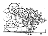
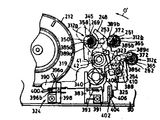
제23도와 제24도에 따르면, 테이프 구동 유니트(91)는 공급 릴축(77), 감는 릴축(78)과 아래로 돌출된 캐스턴(79)의 아래 끝부분을 통과하여 부착판(90)의 아래쪽에 부착된다. 모터(211)는 부착판(90)의 아래쪽에 적당히 고정되고 모터 풀리(213)가 고정된 위체 축(212)이 있다. 조립된 플라이 휠과 캡스턴 풀리(214)는 캡스턴(79)과 가이드 풀리(215)의 아래끝에 고정되고, 캡스턴 를라이 휠에 대해 반재로 또는 플라이 휠로써 동작하고, 부착판(90)의 아래쪽에 회전할 수 있게 부착된다. 벨트(216)가 캡스턴 (79)에 모터축(212)의 회전을 전달하기 위하여 모터 풀리(213), 캡스턴 풀리(214), 가이드 풀리(215) 주위에 끼워진다. 공급 릴축(77), 감는 릴축(78), 캡스턴(79) 사이의 대략 중간 위치에 구동기어(217)가 부착판(90)의 아래쪽에 회전할 수 있게 부착되어 있고, 구동기어(217)와 공급 릴축(77) 사이에 전환기어축(218)이 부착되어 있다. 켑스턴 기어(220)(제22도와 제23도)는 캡스턴(79)의 아래 끝부분에 있는캡스턴 풀리(214)에 고정되고 축방향으로 비교적 넓다. 제 1 과 제 2 구동기어(211과 222)는 (제22도와 제24도) 구동기어축(217)에 회전할 수 있게 부착되고 그 사이에 위치하는 클러치 장치(223)와 함께 움직일 수 있다.According to FIG. 23 and FIG. 24, the tape drive unit 91 passes through the supply reel shaft 77, the winding reel shaft 78, and the lower end of the caster 79 protruding downwardly, Attached to the bottom The motor 211 has an upper body shaft 212 fixed to the bottom of the attachment plate 90 and to which the motor pulley 213 is fixed. The assembled flywheel and capstan pulley 214 are fixed to the lower ends of the capstan 79 and guide pulley 215, acting as a half wheel or flywheel relative to the lie wheel, and below the attachment plate 90. It is attached to rotate. Belt 216 is fitted around motor pulley 213, capstan pulley 214, and guide pulley 215 to transmit rotation of motor shaft 212 to capstan 79. The drive gear 217 is rotatably attached to the lower side of the attachment plate 90 at an approximately intermediate position between the supply reel shaft 77, the reel shaft 78, and the capstan 79. A switching gear shaft 218 is attached between the supply reel shafts 77. The paxton gear 220 (FIGS. 22 and 23) is secured to the capstan pulley 214 at the lower end of the capstan 79 and is relatively wide in the axial direction. The first and second drive gears 211 and 222 are rotatably attached to the drive gear shaft 217 (FIGS. 22 and 24) and can move together with the clutch device 223 positioned therebetween.

클러치 장치(223)는 자기클러티 형태이고, 제 2 구동기어(222)는 자석처럼 자화될 수 있는 자기재료 형태이다. 반고체 재료인 히스테리시스 디스크(224)는 제 1 구동기어(221)의 아랫면에 고정되어 있고, 얇은 플래스틱 와셔(225)는 제 2 구동기어와 디스크(224) 사이의 틈이 최소가 되도록 디스크(224)와 제 2 구동기어(222) 사이에 위치한다. 자속의 누출을 막기 위한 디스크(226)는 제 2 구동기어의 부하방지 회전이 미리 정해진 값을 넘지않는한 제 2 구동기어(228)와 함께 회전하는 제 1 차 구동기거가 자화력에 의해 접속되어 제 2 구동기어 위에 있는 제 1 구동기어(221)와 같이 부착되고, 유지 와셔(227)은 상응하는 기어를 지지하기 위한 구동기어축(217)의 아래끝에있는 고리모양의 홈에 수용된다. 축방향으로 비교적 넓은 전환기어(229)는 이 축에 대한 회전과 축운동을 위한 전환기어축(218)에 부착된다. 나선형 억압 스프링(230)은 전환기어축(218)의 아래끝에 있는 고리 모양의 홈에 수용되어 있는 유지 와셔(231)에 대해 아래쪽으로 축을 밀기 위해 기어(229) 위에 있는 축(218) 주위에 마련되어 있다. 비교적 축방향으로 넓은 공급 릴축 기어(232)는 공급 릴축(77)의 아래 끝부분에 고정 부착되고, 제 1, 제 2 감기 릴축 기어(233과 234)들은 감기 릴축(278)의 아래 끝부분(235)에 부착된다. 감기 릴축의 이 아래 끝부분은 육각형의 횡단면을 갖고, 제 2 감기 릴축 기어(234)는 육각형축의 끝부분(235)의 바깥 주변에 근접 수용되고, 나사(236)에 의해 거기에 고정된다. 제 1 감기 릴축 기어(233)는 감기 릴축(78)에 회전 결합되는 축 끝부분(235)에 미끄러질 수 있도록 육각형 형태의 구멍(237)을 갖는다. 나선형 억압 스프링(238)은 축(78) 주변에 있고, 제24도에 보이는 기어(233과 234)의 중심이 인접하고 있는 위치로부터 축이 상승하는 것을 방지하기 위하여 제 1 감기 릴축(233)의 아래쪽으로 동작한다. 제 1 구동기어(221)는 제 1 구동기어(221)의 모든 축의 위치에서 캡스턴 기어(220)와 맞물리어 수용된다. 캡스턴 기어는 제 1 구동기어(221)의 축 이동에 의해전환기어(229) 또는 제 1 감기 릴축 기어(233)와 함께 선택된 상채로 이동한다. 제 2 구동기어(222)는 제 2 감기 릴축 기어(234)의 수용 여부에 따라 제 1 구동기어(221)와 같이 축 이동한다. 전환기어(229)는 전환기어(229)의 축 위치에 따라 공급 릴축 기어(232)와 방사형으로 수용된다.The clutch device 223 is in the form of a magnetic clutch, and the second drive gear 222 is in the form of a magnetic material that can be magnetized like a magnet. The semi-solid material hysteresis disk 224 is fixed to the lower surface of the first drive gear 221, the thin plastic washer 225 is the disk 224 so that the gap between the second drive gear and the disk 224 is minimal And between the second drive gear 222. The disk 226 for preventing the leakage of magnetic flux is connected to the primary drive gear which rotates together with the second drive gear 228 by the magnetizing force as long as the load preventing rotation of the second drive gear does not exceed a predetermined value. Attached together with the first drive gear 221 over the second drive gear, the retaining washer 227 is received in an annular groove at the lower end of the drive gear shaft 217 for supporting the corresponding gear. A relatively wide diverter gear 229 in the axial direction is attached to the diverter gear shaft 218 for rotation and axial motion about this axis. A helical suppression spring 230 is provided around the shaft 218 above the gear 229 to push the shaft downward relative to the retaining washer 231 received in an annular groove at the lower end of the diverter gear shaft 218. have. A relatively axially wide supply reel shaft gear 232 is fixedly attached to the lower end of the supply reel shaft 77, and the first and second winding reel shaft gears 233 and 234 are attached to the lower end of the winding reel shaft 278 ( 235). This lower end of the winding reel shaft has a hexagonal cross section, and the second winding reel shaft gear 234 is received close to the outer periphery of the end portion 235 of the hexagonal shaft and secured there by a screw 236. The first winding reel shaft gear 233 has a hexagonal hole 237 to slide on the shaft end portion 235 that is rotationally coupled to the winding reel shaft 78. The helical suppression spring 238 is around the shaft 78 and the first winding reel shaft 233 of the first winding reel shaft 233 to prevent the shaft from rising from the position adjacent to the center of the gears 233 and 234 shown in FIG. It works downward. The first drive gear 221 meshes with the capstan gear 220 at positions on all axes of the first drive gear 221. The capstan gear moves with the switching gear 229 or the first winding reel shaft gear 233 to the selected image by the shaft movement of the first drive gear 221. The second drive gear 222 is axially moved together with the first drive gear 221 depending on whether the second winding reel shaft gear 234 is accommodated. The diverter gear 229 is radially received with the supply reel shaft gear 232 according to the axial position of the diverter gear 229.

제22도와 제23도에 의하면, 동작판 지지축(241)은 부착판(90)에 수직으로 서고, 축(241)에 미끄러질 수 있는 슬리브(242)를 갖고, 축(241)의 아래끝(제26A도와 제26(b)도)의 고리모양의 홈에 수용되어 있는 지지 와셔(244)를 향해 나선형 억압 스프링(243)에 의해 아래쪽으로 밀린다.22 and 23, the operating plate support shaft 241 stands perpendicular to the attachment plate 90, has a sleeve 242 that can slide on the shaft 241, and has a lower end ( 26A and 26B) are pushed downward by the helical suppression spring 243 toward the support washer 244 accommodated in the annular groove.

근본적으로 제 1 수평 동작판(245)은 부착판(90)에 대해 제 1 동작판을 수직으로 움직이기 위하여 슬리브(242)의 위 끝부분에 고정된다. 제 1 동작판(245)의 자유로운 끝부분(245a)은 구동기어축(217)을 향해 연장되고, 구동기어와 제 3 구동기어(228)(제24도) 사이의 제 1 구동기어(221)의 중심에 있는 고리모양의 홈(247)에 수용되는 구멍(246)에 부착된다.In essence, the first horizontal operating plate 245 is fixed to the upper end of the sleeve 242 to move the first operating plate perpendicular to the attachment plate 90. The free end portion 245a of the first operating plate 245 extends toward the drive gear shaft 217 and includes a first drive gear 221 between the drive gear and the third drive gear 228 (Fig. 24). It is attached to a hole 246 received in an annular groove 247 at the center of the.

제 1 동작판(245)에 의해 부분적으로 겹쳐진 제 2 동작판(248)은 제 1 동작판의 아래까지 연장되고, 제26A도와 제26(b)도에 보이는 것처럼 동작판(248)에 대해 슬리브(248)가 제한된 수직운동을 허용하기 위해 슬리브(242)에 부착된다. 제 2 동작판(248)은 박편 스프링 재료로 이루어져 있고, 전환기어축(218)을 향해 연장된 자유로운 끝부분(248a)을 갖는다. 이 자유로운 끝(248a)은 전환기어(229)에 있는 돌기(250)를 받아들이는 구멍(249)을 안에 갖는다(제24도).The second operating plate 248 partially overlapped by the first operating plate 245 extends below the first operating plate and is sleeved with respect to the operating plate 248 as shown in FIGS. 26A and 26B. 248 is attached to sleeve 242 to allow limited vertical movement. The second operating plate 248 is made of a laminar spring material and has a free end 248a extending toward the diverter gear shaft 218. This free end 248a has a hole 249 therein for receiving the protrusion 250 in the diverter gear 229 (FIG. 24).

FF 단추(84)와 되감기단추(85)는 축(217과 218)으로부터 일반적으로 떨어져 변환 제 1, 제 2 동작판(245와 248)의 옆에 인접한 부착판(90)에 매달린 관형 부착물(251과 252)안에서 수직으로 움직일 수 있도록 부착된다. 누름단추(84와 85)에 합쳐진 동작아암(253과 254)은 누름단추에서 수평으로 연장되고, 동작판(253과 254)의 자유로운 끝부분으로부터 연장되어 똑바른 돌출부(255와 256)를 갖는다. FF 단추(84)로부터 연장된 동작아암(253)은 제26(a)도의 부재(257)에서처럼 겹쳐진 제 1, 제 2 동작판(245와 248)의 아래부분까지 연장되고, 도감기단추(85)로 부터 연장된 동작아암(254)은 제 1 동작판만을 움직일 수 있도록 제 2 동작판(248) 못미쳐까지 연장되는 제 1 동작판(245) 부분의 아래까지 이른다. 동작아암(254)이 연장된 아래 제 1 동작판(245)부분은 제 26b에서처럼 되감기단추(85)가 위로 눌려지면 동작판(254)의 돌출부(256)를 받아들이기 위한 반원형의 홈집 또는 개폐기(258)로 구성된다.The FF button 84 and the rewind button 85 are generally spaced apart from the axes 217 and 218 and the tubular attachment 251 suspended on the attachment plate 90 adjacent to the first and second operating plates 245 and 248. And 252) to move vertically. The operating arms 253 and 254 joined to the push buttons 84 and 85 extend horizontally at the push buttons and extend from the free ends of the operation plates 253 and 254 to have straight protrusions 255 and 256. The operating arm 253 extending from the FF button 84 extends to the lower portion of the first and second operating plates 245 and 248 overlapped as in the member 257 of FIG. The operating arm 254 extending from) extends below the portion of the first operating plate 245 extending far beyond the second operating plate 248 to move only the first operating plate. A portion of the lower first operating plate 245 with the operating arm 254 extended therein is a semicircular groove or switchgear for receiving the protrusion 256 of the operating plate 254 when the rewinding button 85 is pushed up as in the case of 26b. 258).

테이프 구동 유니트(91)의 여러가지 동작 형태는 다음과 같다.Various operation forms of the tape drive unit 91 are as follows.

제25(a)도의 굵은 선에서 보이는 것처럼 테이프 구동 유니트 (91)가 동작 위치에 있지 않을때, 제 1 구동기어(221)와 전환기어(229)는 그 사이에 있는 수직틈 g1과 제 2구동기어(222)는 제 2 감기 릴축기(234)와 맞물리어 결함하는 상대적으로 낮은 위체에 있다. 이같이 정지나 테이프 구동 유니트(91)가 동작하지 않는 상태에서 FF단추(84)와 되감기단추(85)는 제26(a)도와 제26(b)도의 점선으로 보이는 것처럼 아래쪽으로 되돌아오거나 연장된 위치를 계속 유지한다. 재생 또는 FWD 단추(83)가 위로 눌려지면(동작하지 않거나 정지된 상태에서 구동 유니트(91)가 동작하면) 모터(211)는 제23도의 화살표 d의 방향으로 캡스턴(79)을 회전시키기 위하여 동작하게 된다. 캡스턴 기어(220)를 제 1 구동기어(221)가 채택함에 따라, 제 1 구동기어(221)는 화살표 e의 방향으로 회전하고 제 2 구동기어(222)는 클러치 장치(223)를 통해 같은 방향으로 회전한다. 감기 릴축 기어(234)를 제 2 구동기어(222)가 서로 맞물림에 따라, 감기릴축(78)은 플레이어(70)의 재생 또는 동작 모드에서 캡스턴(79)에 의해 테이프가 구동되면 카세트(71)의 감기 릴에 테이프를 감거나 수용하기 위하여 비교적 느린 속도로 화살표 f의 방향으로 회전한다.When the tape drive unit 91 is not in the operating position, as shown by the thick line in FIG. 25 (a), the first drive gear 221 and the switching gear 229 have the vertical gap g 1 and the second gap therebetween. The drive gear 222 is in a relatively low position that engages with the second winding reel shaft 234 and fails. In such a state that the stop or the tape drive unit 91 is not in operation, the FF button 84 and the rewind button 85 are returned or extended downward as shown by the dotted lines in the 26th (a) and 26th (b) degrees. Keep going. When the play or FWD button 83 is pushed up (when the drive unit 91 is operated while not in operation or stopped), the motor 211 operates to rotate the capstan 79 in the direction of the arrow d in FIG. Done. As the first drive gear 221 adopts the capstan gear 220, the first drive gear 221 rotates in the direction of the arrow e and the second drive gear 222 moves in the same direction through the clutch device 223. Rotate As the second reel gear 222 meshes the reel reel shaft gear 234 with each other, the reel reel shaft 78 is moved to the cassette 71 when the tape is driven by the capstan 79 in the regeneration or operation mode of the player 70. Rotate in the direction of arrow f at a relatively slow speed to wind or accept the tape on the winding reel.

동작하지 않거나 정지 상태에서 테이프 구동 유니트(91)가 다시 동작하면, FF 단투(84)는 제26(a)도의 실선으로 보이는 것처럼 눌려진 위치에서 위로 올라어면 동잗아암(253)의 돌출부(255)는 겹쳐진 부분(257)에서 양동작판(245와 248)의 위쪽으로 동작한다. FF 단추(84)는 올라온 위치에서 감겨지고, 이 다음에 자세히 설명하겠지만 양 동작판(245와 248)은 제26(a)도에서 보이는 것처럼 대응하여, 감기 릴축(78)은 제 1 감기 릴축(223)과 제 1 구동기어(221)의 결합을 통해 화살표 f의 방향으로 비교적 고속으로 회전한다. 또, 테이프의 이런 고솟감기는 카세트(71)에서 감기 릴축에 영향을 미치고, 플레이어(70)의 빨리 보내기 또는 큐 동작 모드에서 필요하다.When the tape drive unit 91 is not in operation or stops again, the FF single throw 84 is raised from the pressed position as shown by the solid line in Fig. 26 (a) and the protrusion 255 of the copper arm 253 In the overlapped portion 257, the two operation plates 245 and 248 operate upward. The FF button 84 is wound in the raised position, and as will be described in detail later, both the operation plates 245 and 248 correspond as shown in FIG. 26 (a), so that the winding reel shaft 78 is the first winding reel shaft ( 223 and the first drive gear 221 rotates at a relatively high speed in the direction of the arrow f. In addition, this high winding of the tape affects the winding reel axis in the cassette 71 and is required in the fast sending or cue operation mode of the player 70.

제 1 구동기어(221)가 FF 단추의 누름에 따라 제일 높은 위치로 올라오게 될때, 기어(221)의 이가 감기 릴축 기어(233)의 이와 즉시 맞물리지 않으면, 감기 릴축 기어는 기어(221)가 회전하는 중에 제25(b)도에 보이는 정상 위치로 제 1 감기 릴축 기어(233)가 되돌아오는 것을 스프링(238)이 허용하도록 기어(221)의 이가 기어(233)의 이와 맞물릴때까지 스프링(238)에 의하여 위로 밀린다.When the first drive gear 221 is raised to the highest position by pressing the FF button, if the teeth of the gear 221 do not immediately engage with the teeth of the reel shaft gear 233, the winding reel shaft gear is rotated by the gear 221. While the spring of the gear 221 is engaged with the teeth of the gear 233 to allow the spring 238 to allow the first winding reel shaft gear 233 to return to the normal position shown in FIG. 25 (b). 238) is pushed up.

정지 또는동작하지 않은 상태에서 테이프 구동 유니트(91)가 다시 동작하면, 제26(b)도의 실선으로 보이는 눌려진 위치에서 감기단추(85)를 누르는 것도 동작아암(254)으로 하여금 제 1 동작판(245)을 채택하고 위로 올리게 하고, 아암(254)으로부터 자유로운 제 2 동작판(248)은 제26(b)도의 실선으로 보이는 것처럼 올라온 판(245) 아래쪽으로 쳐진다. 스프링(243)의 힘에 반하여 올라온 위치를 유지한다.When the tape drive unit 91 is operated again in a stopped or inoperative state, pressing the winding button 85 at the pressed position shown by the solid line in FIG. 26 (b) also causes the operating arm 254 to operate on the first operating plate ( The second operating plate 248, which adopts 245 and is lifted up and free from the arm 254, is struck below the raised plate 245 as shown by the solid line in FIG. 26 (b). The raised position is maintained against the force of the spring 243.

앞 이야기의 결과로, 제 1 구동기어(221)는 제 1 동작판(245)의 자유로운 끝(245a)에 의해 제일 높은 위치로 올라오고, 전환기어(229)로 제 2 동작판(248)의 자유로운 끝부분(248a)에 의한 스프링(230)의 힘에 의하여 제일 높은 위치로 올라온다. 제 1 구동기어(221)와 전환기어(229)가 모두 그들의 제일 높은 위치로 올라오면, 틈 g1이 그 사이에서 유지된다. 그러므로 전환기어(229)는 제 1 구동기어(221)로부터 유리된 상태를 유지하고 제 1 구동기어(221)는 캡스턴 기어(220)과 맞물린 결합을 결합을 계속하고 감기 릴축 기어(233)와 맞물리도록 움직인다.As a result of the foregoing story, the first drive gear 221 is raised to the highest position by the free end 245a of the first operating plate 245, and the switching gear 229 of the second operating plate 248. It is raised to the highest position by the force of the spring 230 by the free end 248a. When both the first drive gear 221 and the shift gear 229 rise to their highest positions, the gap g 1 is maintained therebetween. Therefore, the changeover gear 229 remains free from the first drive gear 221 and the first drive gear 221 continues to engage with the engagement with the capstan gear 220 and engages with the winding reel shaft gear 233. To move.

클러치 장치(2330안의 자화력의 결과로, 제 2 구동기어(222)는 제 1 구동기어가 제일 높은 위치로 움직이로 있는 동안에 제 1 구동기어와 함께 움직이고, 그에 의해 제 2 구동기어(222)는 제 2 감기 릴축 기어(234)로부터 유리된다.As a result of the magnetizing force in the clutch device 2330, the second drive gear 222 moves with the first drive gear while the first drive gear is moving to the highest position, thereby the second drive gear 222. Is liberated from the second winding reel shaft gear 234.

FF 단추(84)가 눌려지면, 모터(211)는, 자세히 설명하면, 캡스턴 기어(220)와 맞물린 결합을 계속하고 감기 릴축 기어(233)와 맞물리도록 움직인다.When the FF button 84 is pressed, the motor 211, in detail, continues to engage engagement with the capstan gear 220 and moves to engage the reel shaft gear 233.

클러치 장치(233)안의 자화력의 결과로, 제 2 구동기어(222)는 제 1 구동기어가 제일 높은 위치로 움직이로 있는 동안에 제 1 구동기어와 함께 움직이고, 그에 의해 제 2 구동기어(222)는 제 2 감기 릴축 기어(234)로부터 유리된다.As a result of the magnetizing force in the clutch device 233, the second drive gear 222 moves with the first drive gear while the first drive gear is moving to the highest position, whereby the second drive gear 222 ) Is liberated from the second winding reel shaft gear 234.

FF 단추(84)가 눌려지면, 모터(211)는, 자세히 설명하면, 캡스턴 기어(220)와 맞물린 결합에 의해 제23도의 화살표 e방향으로 제 1 구동기어(221)의 회전을 야기시켜 동작 모드가 된다. 기어(221)의 이 회전에 응하여 1 차 감기 릴축 기어(223)와 1 차 구동기어(221)가 맞물리게 되므로 화살표 f방향으로 비교적 높은 속도로 감기 릴축(78)이 회전한다. 따라서 고속으로 테이프가 감기는 것이 카세트(71)의 감기 릴에 영향을 받으며 플레이어(70)의 빨리 보내기나 큐 동작 모드가 요구된다.When the FF button 84 is pressed, the motor 211, in detail, causes the rotation of the first drive gear 221 in the direction of the arrow e in FIG. 23 by engagement with the capstan gear 220, thereby operating mode. Becomes In response to this rotation of the gear 221, the primary winding reel shaft gear 223 and the primary drive gear 221 are engaged so that the winding reel shaft 78 rotates at a relatively high speed in the direction of the arrow f. Therefore, the winding of the tape at high speed is affected by the winding reel of the cassette 71, and the fast sending or cue operation mode of the player 70 is required.

FF 단추(84)가 눌려짐에 따라 1 차 구동기어(221)가 가장 높은 위치로 올라갈때, 기어(221)의 이가 감기 릴축 기어(233)의 이에 맞물리지 않으면, 기어(221)의 회전에 따라 스프링(238)이 제25(b)도에 도시된 바와 같이 1 차 감기 릴축 기어(233)의 이에 맞물리지 않으면, 기어(221)의 회전에 따라 스프링(238)이 제25(b)도에 도시된 바와 같이 1 차 감는 릴축 기어(233)가 그의 정상 위치로 되돌아오게 하도록 기어(233)의 이가 (221)의 이에 맞물릴때까지 스프링(238)의 힘에 대하여 기어(22When the primary drive gear 221 ascends to the highest position as the FF button 84 is pressed, if the teeth of the gear 221 do not engage with the teeth of the reel shaft gear 233, the rotation of the gear 221 If the spring 238 does not engage the teeth of the primary winding reel shaft gear 233 as shown in FIG. 25 (b), the spring 238 is shown in FIG. 25 (b) as the gear 221 rotates. As shown, the gear 22 is biased against the force of the spring 238 until the teeth of the gear 233 engage with the teeth 221 of the gear 233 to bring the reel shaft gear 233 back to its normal position.

1)는 위쪽으로 힘을 받는다. 다시 테이프 구동 유니트(91)가 정지되거나 비동작 상태로 되기 시작하면, 제26(b)도에 실선으로 도시된 압압된 위치에 대한 되감기단추(85)의 상향 누름이 동작아암(254)이 접속되어 1 차 동작판(245)을 상승시키며 그 반면에 제26(b)도에 실선으로 도시된 바와 같이 아암(254)의 자유로움으로 인해 2 차 동작판(248)은 상승된 판(245)보다 아래쪽으로 뒤떨어진다.1) are forced upwards. When the tape drive unit 91 again stops or starts to become inoperative, pressing the rewind button 85 upward against the pressed position shown by the solid line in FIG. 26 (b) is connected to the operating arm 254. To raise the primary operation plate 245 while the secondary operation plate 248 is raised due to the freedom of the arm 254 as shown in solid line in FIG. 26 (b). Fall further down

제26(b)도에서 점선으로 표심된 비동작 부분이나 연장된 부분과 실선으로 표시된 상승된 동작 부분 사이에 되감기단추(85)의 타격 S1이 FF 단추(84)의 타격과 유사하더라도, FF 단추(84)는 동작아암(253)의 돌출부(255)의 위 끝면을 통하여 양 동작판(245와 248)을 동작시키고, 동작암(254)의 비슷한 돌출부(256)는 제 1 동작판(245)의 노치(258)에 받아들여진다. 그러므로 되감기단추(85)의 동작에 의해, 제 1 동작판(245)은 동작암(254)의 위 끝면에 의해서만 동작하면, 되감기단추(85)에 의해 올라온 제 1 동작판(245)의 거리는 돌출부(256)이 높이 S2만큼 작아지게 되고, 양판(245와 248)을 통하는 거리는 FF 단추(84)의 동자작 또는 누름에 의해 올라오게 된다.Although the strike S 1 of the rewinding button 85 is similar to the strike of the FF button 84 between the non-operating portion or the extended portion centered in the dotted line in FIG. 26 (b) and the raised operating portion indicated by the solid line, FF The button 84 operates both operating plates 245 and 248 through the upper end surface of the protrusion 255 of the operating arm 253, and the similar protrusion 256 of the operating arm 254 is the first operating plate 245. In the notch 258. Therefore, when the first operating plate 245 is operated only by the upper end surface of the operating arm 254 by the operation of the rewinding button 85, the distance of the first operating plate 245 raised by the rewinding button 85 is a protrusion. 256 becomes small by the height S 2 , and the distance through the plates 245 and 248 is raised by the movement or pressing of the FF button 84.

앞동작의 결과로, 제 1 동작판(245)이 되감기단추(85)의 누름에 따라 올라오고, 올라온 위치에서 잠기면, 자세히 이야기하자면, 캡스턴 기어(220)의 채택을 계속하고 있는 동안, 제 1 구동기어(221)는 제25(a)도의 점선으로 표시한 것처럼 동작판(245)의 자유로운 끝부분(245)에 의하여 중간위치로 수직 상승 이동한다. 제 1 구동기어의 이 중간위치에서, 제 1 구동기어는 전환기어(229)와 망사형 결합을 하게 되고, 제 2 구동기거(222)는 제 1 구동기어(221)와 같이 위로 이동하고 제 2 되감기 릴축에서 유지된다.As a result of the preceding operation, when the first operating plate 245 comes up with the pressing of the rewinding button 85 and is locked in the raised position, in detail, the first operation plate 245 is continued while the capstan gear 220 is being adopted. The drive gear 221 is vertically moved upward to the intermediate position by the free end 245 of the operation plate 245 as indicated by the dotted line in FIG. 25 (a). At this intermediate position of the first drive gear, the first drive gear is meshed with the diverter gear 229, and the second drive gear 222 moves up like the first drive gear 221 and the second It is held on the rewind reel shaft.

그래서, 모터(211)는 되감기단추(85)의 누름 위치에서 제23도의 화살표 e의 방향으로 제 1 구동기어(221)의 회전은 전환기러(229)로 하여금 화살표 g의 방향으로 회전하게끔 한다. 공급 릴축(232)과 전환기어(230)의 힘에 의하여 위로 밀려지고, 그후에 스프링(230)은 제25(a)도에 보이는 정상축 위치로 상기 전환기어 아래쪽으로 되돌아온다.Thus, the motor 211 rotates the first drive gear 221 in the direction of the arrow e in FIG. 23 at the pushed position of the rewind button 85 to cause the diverter gear 229 to rotate in the direction of the arrow g. It is pushed upward by the force of the supply reel shaft 232 and the diverter gear 230, and then the spring 230 is returned below the diverter gear to the normal shaft position shown in FIG. 25 (a).

이후에 자세히 설명하겠지만, 플레이어(70)가 재생, FF, 또 되감기 모드로 이완된 위치에서 정지단추(82)가 눌려지거나 올라오면, 모터(211)는 멈춘다. 정지단추(82)를 플레이어(70)가 FF 모드 또는 되감기 모드일때 느르면, FF 단추(84) 또는 되감기단추(85)는 제26a 또는 제26(b)도의 점선에서 보이는 비동작 상태나 최초의 상태로 되돌아와 풀림으로써, 제26(a)도와 제26(b)도의 점선에서 보이는 것처럼 동작판(245와 248)은 스프링(243)에 의해 되돌아오고, 그 결과로, 구동기어(221,222)와 전환기어(229)는 제25(a)도의 실선에 보이는 가장 낮은 위치로 되돌아온다.As will be described in detail later, the motor 211 is stopped when the stop button 82 is pressed or raised from the position where the player 70 is relaxed in the play, FF, and rewind modes. If the stop button 82 is slow when the player 70 is in the FF mode or the rewind mode, the FF button 84 or the rewind button 85 may be in an inactive state or an initial state as shown by the dotted line in Fig. 26a or 26 (b). By returning to the state and releasing, the operating plates 245 and 248 are returned by the springs 243 as shown by the dotted lines in Figs. 26 (a) and 26 (b), and as a result, the driving gears 221, 222 The changeover gear 229 returns to the lowest position shown by the solid line in Fig. 25 (a).

기술한 테이프 구동 유니트(91)는 구동기어(221과 222), 클러치장치(223), 전환기어(229), 공급 릴축 기어(232)와 되감기 릴축 기어(233과 234)로 구성되는 최소한의 필요한 동작 모드를 얻을 수 있고, 구동기어(221과 222), 전환기어(229)를 수직방향으로 움직이는 선택적인 이동에 의해 플레이어(70)의 필요한 선택을 얻을 수 있다. 테이프 구동 유니트(91)에 쓰이는 비교적 적은 수의 부품은 테이프 구동 유니트 구조를 단순화하고 원가를 절감시키며 수직방향으로의 기어(221,222,229)의 이동에 의해 동작 모드를 선택하는 것은 근본적을 구동 유니트(91)에 필요한 공간을 실제적으로 최소화함으로써 테이프 구동 유니트가 매우 간단한 카세트 테이프 플레이어의 제작을 가능케 한다.The above described tape drive unit 91 is constituted of a minimum required of the drive gears 221 and 222, the clutch device 223, the shift gear 229, the supply reel shaft gear 232 and the rewind reel shaft gears 233 and 234. The operation mode can be obtained, and the necessary selection of the player 70 can be obtained by the selective movement of the drive gears 221 and 222 and the shift gear 229 in the vertical direction. The relatively small number of parts used in the tape drive unit 91 simplifies the tape drive unit structure, reduces the cost, and selects the operation mode by the movement of the gears 221, 222, 229 in the vertical direction. By practically minimizing the space required for the tape drive unit, a very simple cassette tape player can be produced.

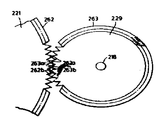
제27(a)도와 제27(b)도에 따르면 위에서 설명한대로 구동기어(221)가 되감기단추(85)의 누름에 따라 중간 위치로 올라오면 제 1 구동기어(221)와 전환기어(229)의 톱니주변(262와 263)이 제 1 구동기어(221)와 전환기어(229)의 맞물린 결합에서 근본적으로 잡음을 없애고 동작을 용이하게 하기 위하여 특별한 형태로 마련되어 있다. 더욱 나아가서, 전환기어(229)의 톱니주변(263)은 아래쪽으로 변환 경사면(264)을 갖는다.According to FIGS. 27A and 27B, when the driving gear 221 rises to an intermediate position according to the pressing of the rewinding button 85 as described above, the first driving gear 221 and the switching gear 229. The teeth 262 and 263 are formed in a special form in order to fundamentally eliminate noise and facilitate operation in the engagement of the first drive gear 221 and the switching gear 229. Furthermore, the tooth circumference 263 of the switching gear 229 has the conversion inclined surface 264 downward.

앞에 말한 것에 의해 제 1 구동기어(221)가 제27(a)도의 점선으로 표시된 중간위치에 원래대로 올라오면, 제 28(a)도에서처럼 기어(221)의 이(262a)가 기어(229)의 이(263A)와 즉각 맞물리지 않더라도 이(263a)의 끝 또는 지정된 끝(263a)은 기어(221)의 회전축쪽으로 수직면으로 놓이는 기어(221)의 평면 나선면(265)와 점접촉 하도록 영향을 미친다.As described above, when the first drive gear 221 is raised to the intermediate position indicated by the dotted line in FIG. 27 (a), the tooth 262a of the gear 221 is in the gear 229 as in FIG. 28 (a). Even if not in immediate engagement with the teeth 263A, the end or designated end 263a of the teeth 263a affects point contact with the planar spiral surface 265 of the gear 221 which lies vertically towards the axis of rotation of the gear 221. .

결과적으로 제27(a)도의 점선에서 보는 것처럼, 앞에 기술한대로 전환기어(229)은 순간적으로 올라오나, 이경우, 기어(229)의 이(263a)의 지정된 끝(263a)은 제27(a)도와 제28(b)도에서처럼 기어가 이(262a와 262b)가 조정되도록 회전하면 기어(221)가 이(262a)의 근저(262b)로 좀더 들어가게 한다. 기어(229)에 있는 경사면(264)은 기어(221과 229)의 즉각적인 맞물림 결합을 용이하게 한다. 기어(229)의 이 주변(263)의 아래로 향한 면이 평탄하면, 즉 기어(229)의 축에 수직이면, 기어(221)의 이난 주변(262)의 면(265)은 위로 향하게 되어 필요한 똑같은 얻을 수 있다. 또한, 기어 이의 특수한 형태가 되감기 모드에서 제 1 구동기어(221)에 의해 전환기어(229)에 수용되는 관계에 대해 설명했지만, 제 1 감기 릴축 기어(233)는 빨리감기 동작에서 기어(221)에의한 기어(233)의 즉각적이고 근본적인 잡음없는 결합을 증진시킬 수 있도록 전환기어(229)에 대해 기술한 것과 비슷하게 이난 주변에 있다는 것을 제24도의 관계에서 알 수 있다.As a result, as shown in the dotted line in Fig. 27 (a), the switching gear 229 is raised as described above, but in this case, the designated end 263a of the tooth 263a of the gear 229 is set to the 27th (a). As shown in Fig. 28 (b), when the gear rotates to adjust the teeth 262a and 262b, the gear 221 enters the bottom 262b of the tooth 262a more. The inclined surface 264 on the gear 229 facilitates the immediate engagement of the gears 221 and 229. If the downward face of the gear 229 is flat, ie perpendicular to the axis of the gear 229, the face 265 of the distal perimeter 262 of the gear 221 will face upwards and the necessary You can get the same. In addition, although the special shape of the gear teeth has been described in relation to being accommodated in the switching gear 229 by the first drive gear 221 in the rewind mode, the first reel shaft gear 233 is the gear 221 in the fast-forward operation. It can be seen from the relationship of FIG. 24 that it is in the periphery similar to that described for the diverter gear 229 so as to promote the immediate and fundamental noiseless engagement of the gear 233 by it.

기어(229)의 이난 주변의 경사진 면(264)이 없으면, 기어(233)와 마찬가지로 기어(221과 229) 또는 기어(221과 233)가 회전축에 수직인 면으로 놓여 있는 서로 면하고 있는 표면에 최초로 접촉하면, 즉, 서로 면접촉하게 되면, 기어 이는 피치가 적으면 기어(221)가 나선형으로 고속회전할때는 위험이 있는데, 기어(221)가 이는 빨리감기 또는 되감기 모드를 선택하면 불필요한 잡음을 없애고 기어의 맞물림 결합을 최소한으로 지연시킬 수 있도록 기어(229) 또는 기어(233)의 한 이에서 다음 이로 재빨리 미끄러진다.Without the inclined face 264 around the distal of the gear 229, the facing surfaces, in which the gears 221 and 229 or the gears 221 and 233 are placed in a plane perpendicular to the axis of rotation, similar to the gear 233 When the first contact, ie, the surface contact with each other, the gear is a small pitch, there is a risk when the gear 221 is rotated at high speed, the gear 221 is a risk of unnecessary noise when selecting the fast-forward or rewind mode It quickly slips from one of gears 229 or gears 233 to the next so that it can eliminate and delay the engagement of the gears to a minimum.

어쨌든 기어(229와 293)의 이의 특수한 형태가 이러한 문제를 해결한다.In any case, its special form of gears 229 and 293 solves this problem.

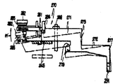
제29도, 제32(a)도와 제33(b)도를 보면, 저부(158)의 헤드(100)의 움직임을 제34(a)도에 보이는 원리 위치에서 제34(b)도에 보이는 정상 재생 또는 FWD 모드의 위치로 움직이게 영향을 미치는 테이프 구동 유니트(91)에 의해 주어지는 구동력을 사용하여 플레이어의 정상 재생(FWD), 큐(CUE) 또는 재확인(REV) 등을 선택적으로 할 수 있는 장치(268)가 있다.Referring to FIG. 29, FIG. 32 (a) and 33 (b), the movement of the head 100 of the bottom 158 is shown in FIG. 34 (b) at the principle position shown in FIG. 34 (a). A device capable of selectively playing the player's normal playback (FWD), cue or reconfirmation (REV), etc. using the driving force given by the tape drive unit 91 that affects the normal playback or moving to the position of the FWD mode. (268).

제29도, 제32(a)도와 제32(b)도를 보면, 재생단추(83)에 대한 부착번호(269)는 캡스턴(79)으로부터 떨어져 대면하는쪽에 기어(221) 주변에 인접한 부착판(90)에 의하여, 재생단추(83)는 부착번호(269)로 미리 정해진 범위안에서 수직 잉동할 수 있도록 부착된다. 헤드저부 동작 레버(270)는 부착 번호(269)와 기거(221)의 주변 사이에 위치하고, 앞부분(271), 뒷부분(272)과 서로 합쳐지는 연결단게(273)를 갖도록 적당한 인조레진 또는 플래스틱 재료로 주형된다. 앞부분(27)의 끝부분은 부착 번호(269)를 향한 면쪽을 따라 연장하는경사진 면(274)이 있다. 이 경사진 면(274)에 대해 뒤쪽, 레버(27)의 앞부분(271)은 오목한 곳(275)과 그곳을 통하여 수직으로 연장하는 통로(276)가 있다. 위로 향한 동작암(277)은 (272)의 끝 또는 뒷부분에 있고, 암(277)에서 수직으로 연장된 중앙 틈(278)에 의하여 뒷부분(272)에 인접해서 두갈래로 갈라진다. 또한 수평 틈(279)은 앞부분(271)의 윗표면의 아래로 연장된 부분이 절단되어 레버(270)의 단계(273)에서 형성된다(제34(a)도와 제34(b)도).Referring to FIG. 29, FIG. 32 (a) and FIG. 32 (b), the attachment number 269 for the regeneration button 83 is adjacent to the gear 221 around the gear 221 on the side facing away from the capstan 79. By 90, the reproducing button 83 is attached to the attachment number 269 so as to vertically swivel in a predetermined range. The head bottom operating lever 270 is located between the attachment number 269 and the periphery of the girders 221 and is made of synthetic resin or plastic material suitable to have a connecting portion 273 that merges with the front portion 271 and the rear portion 272. Are molded into. The end of the front portion 27 has an inclined surface 274 extending along the side toward the attachment number 269. Behind this inclined surface 274, the front portion 271 of the lever 27 has a recess 275 and a passage 276 extending vertically therethrough. The upwardly actuating arm 277 is at the end or back of 272 and is bifurcated adjacent to the back 272 by a central gap 278 extending vertically from the arm 277. In addition, the horizontal gap 279 is formed at the step 273 of the lever 270 by cutting the portion extending downward of the upper surface of the front portion 271 (Fig. 34 (a) and 34 (b)).

톱니 멈춤 레버(281)는 경사면(274)을 따르는 레버(270)의 압부분(271)의 아래 표면을 향해 위치하고 앞부분(271)의 끝에 있는 핀(282)에 수직으로 부착된다. 톱니 멈춤 레버(281)는 톱니 멈춤 이(283)와 자유로운 끝에 있는 정지 돌출부(284)를 갖도록 플래스틱 재료로 주형된다. 톱니 멈춤 레버(281)는 비틀림 스프링(285)을 통하여 제31도의 화살표 i의 방향으로 레버(270)에 대해 수직으로 편심되고, 톱니 멈춤 레버(281)의 정지 돌출부(284)는 톱니 멈춤 이(283)가 기어를 향한 레버(270)쪽으로 떨어져 돌출한 위치에 톱니 멈춤 레버(281)의 편심된 스프링의 수직 운동을 제한하기 위하여 레버(270)에 있는 접합점(286)에 맞물린다.The tooth stop lever 281 is located toward the bottom surface of the pressing portion 271 of the lever 270 along the inclined surface 274 and is attached perpendicularly to the pin 282 at the end of the front portion 271. The tooth stop lever 281 is molded from a plastic material to have a tooth stop tooth 283 and a stop protrusion 284 at the free end. The tooth stop lever 281 is eccentrically perpendicular to the lever 270 in the direction of arrow i of FIG. 31 through the torsion spring 285, and the stop projection 284 of the tooth stop lever 281 is a tooth stop tooth (2). 283 engages the abutment point 286 on the lever 270 to limit the vertical movement of the eccentric spring of the toothed lever 281 in a position projecting away toward the lever 270 towards the gear.

제32(a)도와 제32(d)도 제37도에서 보는 것처럼, 헤드저부 동작 레버(270)의 앞부분(271)은 제 1 동작판(245)의 아랫면 하부까지 연장되고, 통로(276)를 통해 부착판(90)에 매달린 안내핀(288)을 받아들이고, 지지 레버(270)의 아래끝에 와셔(289)를 고정한다. 동작암(277)을 헤드저부(158)의 자유로운 끝부분(158a) 아래 부착판(90)에 있는 직사각형의 안내구멍(290)을 통해 위로 뻗힌다.32 (a) and 32 (d), as shown in FIG. 37, the front portion 271 of the head bottom operating lever 270 extends to the bottom lower surface of the first operation plate 245, and the passage 276 Accept the guide pin 288 suspended on the mounting plate 90 through, and to fix the washer 289 to the lower end of the support lever 270. The operating arm 277 extends upward through a rectangular guide hole 290 in the attachment plate 90 below the free end 158a of the head bottom 158.

제30도에 보이는 것처럼 동작암(277)은 지지 톱니 멈춤쇠(291)를 한정하기 위하여 반대쪽, (291')에 노치를 낸다. 암(277)이 안내구멍(290)에 위로 향하여 삽입되면, 지지 톱니 멈춤쇠(291)는 노치(291')가 안내구멍(290)의 반대편 끝부분을 받아들일때까지 그 사이에 있는 틈(278)을 서로 좁히도록 옆쪽으로 탄력성 있게 밀린다. 그후, 레버(270)는 직사각형 구멍(290)에 암(277)의 수용에 의해 허용되는 한도까지 세로방향으로 움직이도록 판(90) 아래에 부착된다. 또한 암(270)은 구멍(290)을 따라 암의 어떤 위치에서도 지레받침점처럼암(277)을 향해 옆으로 흔들릴 수 있다. 암(270)에 매달린 고리(292)와 레버(270) 사이에 연장된 장력 스프링(293)에 의해 제32(a)도의 화살표 J와 K방향으로 세로와 수직으로 편심된다.As shown in FIG. 30, the operating arm 277 notches on the opposite side 291 'to define the support tooth detent 291. When the arm 277 is inserted upward into the guide hole 290, the support tooth detent 291 is provided with a gap therebetween until the notch 291 'accepts the opposite end of the guide hole 290. 278) and pushed elastically to the side to narrow each other. Thereafter, the lever 270 is attached to the rectangular hole 290 below the plate 90 to move longitudinally to the extent allowed by the reception of the arm 277. Arm 270 may also swing sideways toward arm 277 like a support point at any position of the arm along hole 290. A tension spring 293 extending between the ring 292 and the lever 270 suspended from the arm 270 is eccentric vertically and vertically in the direction of arrows J and K of FIG. 32 (a).

제29도, 제32(a)도 내지 제32(d)도, 제33(a)도와 제33(b)도에서 보이는 것처럼, 인조레진 또는 플레스틱 재료로 주형된 제 1 구동기어(221)는 3개의 같은 위치의 구동단자들(285)과 같은 여러개의 구동단자의 아래면에 부착되고, 레버(281)의 톱니 멈춤 이(283)가 재생단추(83)의 동작에 따라 구동단자(295)의 원통 통로로 돌출되면 톱니 멈춤 레버(281)의 주변에 위치한다.First drive gear 221 molded of synthetic resin or plastic material, as shown in FIGS. 29, 32 (a) to 32 (d), 33 (a) and 33 (b) Is attached to the underside of several drive terminals, such as the drive terminals 285 in three same positions, and the tooth stop 283 of the lever 281 is driven by the operation of the regeneration button 83. When protruded into a cylindrical passage of), it is positioned around the tooth stop lever 281.

제29도, 제33(a)도와 제33(b)도에서 보이는 것처럼, 동작암(296)은 경사면(274) 지역의 레버(270) 아래에 부착 번호(269)로부터 연장될 수 있도록 재생단추(83)와 같이, 부착되고, 이 동작암(296)은 단추(83)가 눌려지면 경사진 면과 부드럽게 접촉하게 하기 위하여 경사면(274)에 일반적으로 평행인 경사면(297)에 부착된다. 플레이어(70)의 FWD, CUE와 REV 모드의 동작은 위에 기술한 장치(268)에 의해 다음과 같이 이루어진다.As shown in FIGS. 29, 33 (a) and 33 (b), the operating arm 296 can be extended from the attachment number 269 below the lever 270 in the inclined surface 274 region. As shown at 83, this operating arm 296 is attached to an inclined surface 297 generally parallel to the inclined surface 274 to make smooth contact with the inclined surface when the button 83 is pressed. Operation of the FWD, CUE and REV modes of the player 70 is performed by the apparatus 268 described above as follows.

제32(a)도에 따르면, 비동작 상태나 정지상태에 있으며, 레버(270)는 화살표 J와 K의 방향으로 스프링(293)에 의하여 밀리고, 톱니 멈춤 레버(281)의 톱니 멈춤 이(283)가 기어(221)의 구동단다(295)의 이동로의 외부에 있도록 동작암(296)이 경사면(274)으로부터 떨어져 있으면 재생단추(83)는 동작하지 않거나 이완된 위치에 있게 된다(제 33(a)도).According to FIG. 32 (a), in the inoperative state or the stationary state, the lever 270 is pushed by the spring 293 in the directions of arrows J and K, and the tooth stop teeth 283 of the tooth stop lever 281. If the operating arm 296 is separated from the inclined surface 274 so that is outside the movement path of the drive end 295 of the gear 221, the regeneration button 83 is not operated or is in a relaxed position (Thirty-third) (a) degrees).

또한, 동작하지 않거나 정지상태에서, 차폐판(162)의 정지부분(164)은 레버(270)의 틈(278)에 삽입되고 레버의 동작암(277)은 제34(a)도에 보이는 위치로 헤드(100)가 자리잡도록 스프링(163)에 의해 밀린 헤드저부(158)의 자유로운 끝부분(158a)의 뒤에 수용된다. 비동작 상태나 정지상태에서 카세트(71)가 플레이어(70)안으로 장진되고, 재생단추(83)가 제33(b)도에 보이는 위치인 위로 눌려지면, 동작암(296)의 경사면(297)은 레버(270)의 경사면(274)위에서 동작한다.Further, in the non-operating or stationary state, the stop portion 164 of the shield plate 162 is inserted into the gap 278 of the lever 270 and the operating arm 277 of the lever is in the position shown in FIG. 34 (a). It is received behind the free end 158a of the head bottom 158 pushed by the spring 163 to set the furnace head 100. When the cassette 71 is pushed into the player 70 in the non-operating state or the stationary state, and the playback button 83 is pressed upward, which is the position shown in FIG. 33 (b), the inclined surface 297 of the operating arm 296 is pressed. Operates on the inclined surface 274 of the lever 270.

제 1동작판(245)은 앞레버 부분(271)의 아래쪽으로 지탱하고 있기 때문에, 경사면(274)에 경사를 이룬 면(297)의 압력에 따라 제 1 동작판의 위로 향한 움직임은 저항을 받고, 그에 따라 이 압력은 제33(b)도의 화살표 ι방향으로 쐐기 작용 또는 힘이 된다. 그 결과로 레버(270)는 지레받침인 동작암 부분(277)에 대해 제32(b)도의 화살표 K방향으로 수직 이동하게 된다. 위로 눌려진 위치로 재생단추(83)가 잠기면, 이후에 자세히 기술되듯이 레버(270)는 제32(b)도에 보이는 것처럼 수직한 위치에 머물고, 그 결과로, 톱니 멈춤 레버(281)의 이(283)는 제 1 구동기어(221)의 구동단자(295)의 이동원형 통로안으로 연장된다.Since the first operating plate 245 supports the lower side of the front lever portion 271, the upward movement of the first operating plate is resisted by the pressure of the surface 297 inclined to the inclined surface 274. Thus, this pressure is wedge action or force in the direction of arrow? In Fig. 33 (b). As a result, the lever 270 is moved vertically in the direction of the arrow K of FIG. 32 (b) with respect to the actuating arm portion 277. When the regeneration button 83 is locked in the upwardly depressed position, the lever 270 stays in a vertical position as shown in FIG. 32 (b), as will be described in detail later, and as a result, the teeth of the tooth stop lever 281 Reference numeral 283 extends into the moving circular passage of the drive terminal 295 of the first drive gear 221.

앞에 언급했듯이, 플레이어(70)의 재생 또는 동작 모드를 선택하기 위하여 재생단추(83)를 누르는 것은 테이프 구동 유니트(91)을 제32(b)도의 화살표 e의 방향으로 제 1 구동기어(221)의 회전에 영향을 미치게 된다. 기어(221)의 이 회전이 시작된 직후에, 구동단자(295)중의 하나는 톱니 멈춤 레버(281)의 이(283)를 수용하고, 톱니를 통해, 장력 스프링(293)의 힘에 대향하여 제32(c)도의 화살표 J방향인 세로로 레버(270)를 구동한다.As mentioned above, pressing the play button 83 to select the play or operation mode of the player 70 causes the tape drive unit 91 to drive the first drive gear 221 in the direction of the arrow e in FIG. 32 (b). This affects the rotation of. Immediately after this rotation of the gear 221 begins, one of the drive terminals 295 receives the teeth 283 of the tooth stop lever 281 and, through the teeth, opposes the force of the tension spring 293. The lever 270 is driven vertically in the direction of the arrow J in Fig. 32 (c).

화살표 J방향으로의 레버(270)의 세로 움직임은 경사면(274)을 제32(d)도의 점선에서 보이는 것처럼 최후까지 단추(83)의 동작암(396)의 경사를 이루는 면(397)에 대해 미끄러지게 하고, 레버(270)는 경사면(274)(제31도)에 인접한 오목한 곳(275)이 동작암(296)의 경사면(297)을 가리키는 세로로, 자리잡은 위치로 도달한다.The longitudinal movement of the lever 270 in the direction of the arrow J causes the inclined surface 274 to be inclined with respect to the inclined surface 397 of the operating arm 396 of the button 83 to the end as shown by the dotted line in FIG. 32 (d). Sliding, the lever 270 reaches a longitudinally seated position where a recess 275 adjacent the inclined surface 274 (FIG. 31) points to the inclined surface 297 of the operating arm 296.

그에 따라, 장력 스프링(293)은 실선으로 보이는 위치에 제32(d)도의 화살표 K방향으로 지레받침점인 동작암부분(277)에 대한 축 레버(270)에 영향을 미치고, 동작암(296)의 위 끝은 소위 전진된 위치에 레버(270)를 잠그기 위하여 오목한 곳(275)에 수용된다. 제32(d)도의 화살료 k방향으로의 레버(270)의 수직 이동은 제 1 구동기어(221)의 구동단자(295)의 통로로부터 톱니 멈춤 레버(281)의 이(283)를 제거하는데 효과적이다. 레버(270)가 원래 위치 또는 되돌아온 위치에서 (제34(a)도) 전진된 위치(제 34(b)도) 화살표 J방향인 (제 32(c)도)세로로 움직이는 동안, 레버(270)의 동작암(277)은 안내구멍(290)을 따라 움직이고 같은 방향으로 헤드저부(158)의 자유로운 끝부분(158a)을 위치하게 한다. 그리하여, 헤드저부(158)는 비틀림 스프링(163)의힘에 반하여 제13도의 화살표 b'의 방향인 축(157)의 주위에 수직으로 위치하고 제34(b)도에서처럼 재생 헤드(100)는 카세트(71)안에 비교적 깊게 삽입되고 미리 지정된 압력으로 테이프 지지 패드(301)를 향하여 테이프(300)를 민다. 비슷하게, 핀치 롤러(101)는 장력 스프링(167)의 힘에 반하여 테이프(300)를 통해 캡스턴(79)과 압력 접촉하게 된다.Accordingly, the tension spring 293 affects the shaft lever 270 for the operating arm portion 277, which is the lever support point in the direction of the arrow K in FIG. 32 (d) at the position shown by the solid line, and the operating arm 296. The upper end of is received in a recess 275 to lock the lever 270 in the so-called advanced position. The vertical movement of the lever 270 in the direction of the arrow material k in FIG. 32 (d) removes the teeth 283 of the tooth stop lever 281 from the passage of the drive terminal 295 of the first drive gear 221. effective. While the lever 270 moves from its original position or the returned position (degree 34 (a)) to the advanced position (degree 34 (b)) in the arrow J direction (degree 32 (c)), the lever 270 Operation arm 277 moves along guide hole 290 and positions free end 158a of head bottom 158 in the same direction. Thus, the head bottom 158 is located vertically around the axis 157 in the direction of arrow b 'in FIG. 13 against the force of the torsion spring 163 and the reproduction head 100 is arranged in a cassette (as shown in FIG. 34 (b)). The tape 300 is pushed toward the tape support pad 301 at a predetermined pressure and inserted relatively deep in 71. Similarly, pinch roller 101 is in pressure contact with capstan 79 through tape 300 against the force of tension spring 167.

FWD 모드로 전환되면, 위에 기술한대로, 테이프(300)는 재생헤드(100)가 동작하거나 테이프(300)에 기록된 스테레오 신호를 재생하는 동안 캡스턴(79)과 핀치 롤러(101)의 상호 동작에 의해 일정한 속도로 구동된다.Once in the FWD mode, as described above, the tape 300 may be subjected to the interaction of the capstan 79 and the pinch roller 101 while the playhead 100 is operating or playing back the stereo signal recorded on the tape 300. Is driven at a constant speed.

FWD 모드로 전환되면, 위에 기술한대로, 테이프(300)는 재생헤드(100)가 동작하거나 테이프(300)에 기록된 스테레오 신호를 재생하는 동안 캡스턴(79)과 핀치 로러(101)의 상호 동작에 의해 일정한 속도로 구동된다.Once in FWD mode, as described above, the tape 300 may not be able to interact with the capstan 79 and the pinch roller 101 while the playhead 100 is operating or playing back a stereo signal recorded on the tape 300. Is driven at a constant speed.

FWD모드에서 위에 기술한대로 그리고 제35(b)도의 실선으로 도시된대로, 전진한 위치로의 레버(270)의 움직임은 제 1 동작판(245)의 주변 부분이 레버(270)의 틈이나 아래가 깍인곳(279)에 들어가게 하고 거기에 머물게 한다.As described above in the FWD mode and as shown by the solid line in FIG. 35 (b), the movement of the lever 270 to the advanced position is such that the peripheral portion of the first operating plate 245 is located at or below the gap of the lever 270. Enter the cutout (279) and stay there.

플레이어(70)가 FWD 또는 재생 로드에 있을때 FF 단추(84)가 위로 눌려지면, 테이프(300)의 빨리보내기 구동은 재생단추(83)가 눌려진 위치에서, 이후에 자세히 기술하겠지만, 플레이어의 CUE 모드를 이루기 위하여 잠겨져 있는 동안 수행된다. 더 나아가서, FF 단추(84)가 제26(a)도의 실선처럼 동작위치인 위로 눌려지면, 동작암(253)은 제35(b)도의 실선에서 보이는 것처럼 원래 위치 또는 되돌아온 위치에서 점선으로 보이는 올라온 위치로 올라가도록 힘을 받는다. 제 1 동판(245)은 FWD 모드를 이루기 위하여 화살표 J의 방향으로 전진하면 레버(270)의 틈으로 수용되기 때문에 FF 단추(84)의 누름에 따라 제 1 동작판(245)의 위로의 이동이나 자리잡음은, 제34(b)도와 제35(b)도의 점선의 위치로, 지레받침점인 동작암 부분(277)에 대해 화살표 m인 방향으로 레버(270)의 수직운동을 일으킨다. 화살표 m인 방향으로의 레버(270)의이러한 수직운동은 재생단추(83)의 동작암(296)의 위 끝으로부터 레버(270)의 오목한 곳(275)의 이탈을 야기시키고, 그에 의해 레버(270)는 제32(a)도에 보이는 원래 위치 도는 이완된 위치로 장력 스프링(239)에 의하여 되돌아 오도록 풀려진다.If the FF button 84 is pushed up when the player 70 is in FWD or playback load, the fast drive operation of the tape 300 will be described in detail later in the position where the play button 83 is pressed, but in the player's CUE mode. It is performed while locked to achieve Further, when the FF button 84 is pushed up in the operating position like the solid line in Fig. 26 (a), the operating arm 253 is raised as shown by the dotted line in the original position or in the returned position as shown in the solid line in Fig. 35 (b). Forced to climb to position Since the first copper plate 245 advances in the direction of the arrow J in order to achieve the FWD mode, the first copper plate 245 is accommodated in the gap of the lever 270, so that the first movement plate 245 moves upward when the FF button 84 is pressed. Positioning is the position of the dotted line of FIG. 34 (b) and FIG. 35 (b), which causes the vertical movement of the lever 270 in the direction of the arrow m with respect to the operating arm portion 277 which is the support point. This vertical movement of the lever 270 in the direction of the arrow m causes the recess 275 of the lever 270 to deviate from the upper end of the operating arm 296 of the regeneration button 83, whereby the lever ( 270 is released to be returned by tension spring 239 to its original or relaxed position shown in FIG. 32 (a).

레버(270)의 이러한 되돌아오는 동작과 그로 인한 헤드저부(158)의 자유로운 끝부분에 수용된 동작암 부분(277)은 비틀림 스프링(163)이 제13도의 화살표 b의 방향인 헤드저부(158)에 수직으로 되돌아오는 것을 허용함으로써 재생 헤드(100)가 제34(a)도에 보이는 것 원래 위치 또는 되돌아온 위치에 이동하게 된다. 재생 헤드(100)의 되돌아온 위치에서, 헤드는 테이프(300)와 가볍게 접촉하기 위하여 카세트(71)안에 조금 삽입된채로 있다.This returning motion of the lever 270 and the resultant motion arm portion 277 received at the free end of the head bottom 158 is such that the torsion spring 163 is connected to the head bottom 158 in the direction of arrow b in FIG. By allowing it to return vertically, the playhead 100 is moved to its original or returned position as shown in FIG. 34 (a). In the retracted position of the reproduction head 100, the head remains slightly inserted in the cassette 71 in order to lightly contact the tape 300.

FF 단추(84)가 눌려지기 전에 재생 또는 FWD 단추(83)가 동작 위치로 눌려져 있으면, 단추(84)는 눌려진 또는 동작 위치에 감겨지지 않고 재생 단추(83)는 눌려진 동작 위치에 계속 잠겨있게 된다. 그리하여, 제32(a)도에 보이는 되돌아온 또는 원래의 위치로 되옮겨진 레버(270)를 단추(83)의 동작암(296)의 경사면(297)에 가볍게 접촉하여 경사면(274)을 갖는다. 결과적으로, FWD 레버(270)는 제34(a)도와 제35(a)도의 실선으로 표시된 것처럼 완전히 수평위치로 되돌아오기보다는 점선으로 표시된 것처럼 약간의 경사진 상태로 있게 된다. 재생 또는 FWD 단추(83)가 미리 물려져 있을 때 FF 단추(84)를 누르면, 테이프 구동 유니트(91)는 테이프에 기록된 스테레오 신호가 헤드(100)에 의하여 재생되는 동안 테이프(300)가 카세트(71)의 감기 릴에 빨리 감겨지는 CUE 상태가 될 것이다. FF 단추가 CUE 상태가 되도록 눌려진 후 FF 단추(84)가 이완되면, 단추(84)는 제26(a)도의 점선으로 보이는 원래의 또는동작하지 않은 위치로 되돌아오고, 동시에 제 1 동작판(245)은 레버(270)의 앞부분(271)을 아래로 누른것과 마찬가지로 제35(a)도의 실선으로 보이는위치인 아래쪽으로 되돌아온다.If the play or FWD button 83 is pressed to the operating position before the FF button 84 is pressed, the button 84 is not wound to the pressed or operating position and the play button 83 remains locked at the pressed operating position. . Thus, the lever 270 returned to the returned or original position shown in FIG. 32 (a) is lightly contacted with the inclined surface 297 of the operating arm 296 of the button 83 to have the inclined surface 274. As a result, the FWD lever 270 is in a slightly inclined state as indicated by the dotted line, rather than completely returned to the horizontal position as indicated by the solid line of FIGS. 34 (a) and 35 (a). If the FF button 84 is pressed when the playback or FWD button 83 is pre-dipped, the tape drive unit 91 causes the tape 300 to be cassettes while the stereo signal recorded on the tape is played back by the head 100. The winding reel of 71 will be in a CUE state quickly wound. When the FF button 84 is relaxed after the FF button is pressed to the CUE state, the button 84 returns to the original or inoperative position shown by the dotted line in FIG. 26 (a), and at the same time the first operating plate 245 ) Returns to the bottom, which is the position shown by the solid line in FIG. 35 (a), similarly to pressing down the front portion 271 of the lever 270.

또, 레버(270)는 제 35(a)도의 화살표 m'인 방향으로 수직이동하고 그 결과를 레버(270)가 경사면(274)는 동작암(296)의 경사면(297)과 누름 접촉하게 되고 결과적으로 쐐기 작용은 레버(270)를 제32(b)도의 화살표 K'의 방향으로 다시 수직이동하게 함으로써 레버(281)의 톱니 멈춤 이(283)는 기어(221)의 구동단자(295)의 이동 통로 안으로 다시 돌출된다. 그리하여, FWD 또는재생 모드로 변환하는 경우에 있어서, CUE 모드로부터 다시 재생 또는 FWD 단추(83)가 전진 위치에 감겨져 있는 동안 영향을 받고, 그에 따라 플레이어(70)는 확인 또는 REV 모드가 된다. REV 모드에서 되감기를 끝내기 위하여 그후에 되감기단추(85)가 이완되면 언제나, 플레이어(70)는 재생 또는 FWD 모드로 다시 자동적으로 돌아간다.In addition, the lever 270 moves vertically in the direction of the arrow m 'in FIG. 35 (a), and as a result, the lever 270 comes into contact with the inclined surface 297 of the operating arm 296. As a result, the wedge action causes the lever 270 to vertically move again in the direction of the arrow K 'in FIG. 32 (b), so that the tooth stop 283 of the lever 281 is driven by the drive terminal 295 of the gear 221. It protrudes back into the passage. Thus, in the case of switching to the FWD or playback mode, playback from the CUE mode is effected again while the FWD button 83 is wound at the forward position, and thus the player 70 enters the confirmation or REV mode. Whenever the rewind button 85 is subsequently relaxed to end the rewind in the REV mode, the player 70 automatically returns back to playback or FWD mode.

플레이어(70)가 재생 또는 FWD 형태에서 정지 단추(80)가 위로 눌려지면, 재생 또는 FWD 단추(83)는 눌려진 또는 동작 위치에서 이완되고, 그에 따라 제33(a)도에 보이는 원래의 또는 동작하지 않는 위치로 되돌아간다. 앞의 결과로, 단추(83)의 동작암(296)의 위치인 레버(270)의 오목한 곳(275)으로부터 이탈되고 그에 의해 스프링(293)을 통해 제32(a)도에 보이는 되돌아온 또는 원래의 위치로 다시 돌아가도록 자유로워진다. 레버(270)의 이러한 되돌아오는 움직임은 헤드저부(158)가 제34a]도에 보이는 원래 위치인 헤드(100)에 되돌아가는 것을 허용하고, 그에 따라 플레이어(70)를 동작하지 않거나 정지 상태를 유지한다.When the player 70 is pressed up in the play or FWD form, the stop button 80 is pushed up, the play or FWD button 83 is relaxed at the pressed or operating position, and thus the original or motion shown in FIG. 33 (a). Return to the position not to. As a result of the preceding, a retracted or original from the recess 275 of the lever 270, which is the position of the operating arm 296 of the button 83, is thereby shown in figure 32 (a) through the spring 293. Free to return to the position of. This returning movement of the lever 270 allows the head bottom 158 to return to the head 100, which is the original position shown in FIG. 34a, thus disabling or keeping the player 70 stationary. do.

플레이어(70)의 여러가지 동작 모드를 선택하기 위해 기술한 장치(260)에서, 경사면(274)의 수용에 따라 레버(270)의 재생단추(83)의 암(296)의 동작은 톱니 멈춤 레버(281)의 이(283)가 구동단자(295)의 이동통로 안으로 돌출되는 위치에 레버(270)의 살짝 옆으로의 움직임에 영향을 미치기 위한 것이다. 그후, 레버(270)의 전진된 위치로의 근본적인 세로 움직임, 동작 위치로 헤드를 움직이는 것과 캡스턴(79)과 핀치 롤러(101)를 받아들이기 위한 헤드저부(158)의 그에 상응하는 움직임은 모터(211)에 의하여 구동기어(221)의 회전에서 힘을 얻는다. 전진된 위치에 도달하면, 레버(270)는 오목한 곳(275)에 동작암(296)의 수용에 의하여 잠기고, 이 맞물림은 레버(270)가 구동단자(295)의 통로로부터 톱니 멈춤 이(283)가 재이탈할 수 있도록 옆으로 움직이거나 수직으로 움직일 수 있게 한다.In the device 260 described for selecting various operating modes of the player 70, the operation of the arm 296 of the regeneration button 83 of the lever 270 in accordance with the reception of the inclined surface 274 is a tooth stop lever ( The teeth 283 of the 281 are intended to affect the movement of the lever 270 to the side slightly in the position where the driving terminal 295 protrudes into the movement passage. Thereafter, the fundamental longitudinal movement of the lever 270 to the advanced position, the movement of the head to the operating position, and the corresponding movement of the head bottom 158 to receive the capstan 79 and the pinch roller 101 are performed by a motor ( The force is obtained by the rotation of the drive gear 221 by 211). When the advanced position is reached, the lever 270 is locked by the reception of the operating arm 296 in the recess 275, which engages the lever 270 with the toothed tooth 283 from the passageway of the drive terminal 295. ) Move sideways or vertically to allow retraction.

위 동작동안, 레버(270)는 세로방향과 그의 수직양 방향으로 움직일 수 있고, 이 두가지 움직임에 대해 레버(270)에 유지력을 주는데 효과적인 한개의 장력 스프링(293)을 갖는다. 또한, 기술한 장치(268)는 비교적 단순한 몇단계로 조립할 수 있는 최소한의 부품으로 구성된다. 모터(211)이 회전력은 재생 또는 FWD 모드를 이루기 위한 레버(270)의 근본적인 세로 움직임이 영향을 미치는데 쓰이기 때문에, 재생 FWD 단추(83)는 매우 가벼운 또는 살쪽 만지기만 하여도 늘려지는 또는 동작 위치가 되어 동작하는 형태의 것이 될 수 있다.During the above operation, the lever 270 can move in both the longitudinal direction and its vertical direction, and has one tension spring 293 which is effective in giving the lever 270 a holding force for both movements. In addition, the described device 268 is composed of a minimum number of parts that can be assembled in a few relatively simple steps. Since the rotational force of the motor 211 is used to influence the fundamental longitudinal movement of the lever 270 to achieve a regeneration or FWD mode, the regeneration FWD button 83 is stretched or moved only with a very light or fleshy touch. It can be of the type that operates.

장치(268)는 단자(295)중의 하나가 단추(83)의 위로 눌림에 따라 제36도의 화살표k'의 방향으로 레버(270)가 옆으로 이동하는 순간에 톱니 멈춤 이(283)를 간섭하는 경우에 톱니 멈춤 레버(281)나 구동단자(295)에 충격을 주지 않기 위한 안전기구(304)를 갖는다. 제30도, 제36도, 제37도에 보이는 것처럼 축핀(282)이 헤드(305)에 부착되고, 레버(270)의 끝부분에 매달린 돌기(306)안에 아래로부터 압착 부착된다. 톱니 멈춤 레버(281)는 이(283)로부터 떨어진 끝부분에 관통형 구멍(307)을 갖고, 이 구멍(307) 위에 부착되므로 톱니 멈춤 레버(281)는 돌기(306)의 축에 대해 화살표 i와 i'방향으로 수직이동할 수 있다. 구멍(307)의 직경은 돌기(306)의 외경보다 약간 크므로 레버(281)는 화살표 n와 m'의 방향으로 자유로이 수직이동할 수 있다.Device 268 interferes with tooth stop 283 at the moment the lever 270 moves sideways in the direction of arrow k 'of FIG. 36 as one of the terminals 295 is pushed over button 83. FIG. In this case, it has a safety mechanism 304 for not impacting the tooth stop lever 281 or the drive terminal 295. As shown in FIG. 30, FIG. 36, and FIG. 37, the shaft pin 282 is attached to the head 305, and is press-bonded from below in the protrusion 306 suspended by the end of the lever 270. As shown in FIG. The toothed stop lever 281 has a through hole 307 at the end away from the tooth 283 and is attached over the hole 307 so that the toothed stop lever 281 is an arrow i with respect to the axis of the projection 306. And can be moved vertically in the i 'direction. Since the diameter of the hole 307 is slightly larger than the outer diameter of the projection 306, the lever 281 can move freely vertically in the directions of arrows n and m '.

비틀림 스프링(285)은 끝부분(285a와 285b) 그리고 헤드(305)와 톱니 멈춤 레버(281)사이에 있는 축핀(282)주위까지 연장하는 중간 코일부분(285c)을 포함하는 것을 알 수 있다. 끝부분(285a와 285b)은 레버의 아래표면으로부터 돌출할 수 있도록 레버(270)의 끝부분에 톱니 멈춤 레버(281)와 함께 주형된 스프링 고리(308과 309)에 대해 버틴다. 장착되면, 비틀림 스프링(285)의 코일 부분(285c)은 톱니 멈춤 레버(281)가 레버(270)의 정지점(286)에 접합점(284)을 수용하도록 제36도의 화살표 i방향으로 편심되도록 하고, 제37도의 화살표 n의 방향으로 수직으로 레버(281)를 밀어 억합함으로써 비틀림 그리고 수직으로 모두 부하를 받게 되고, 그에 따라 레버(281)를 레버(270)의 앞부분(271)의 아래 표면에 근접 접촉하게 밀게 된다.It can be seen that the torsion spring 285 includes ends 285a and 285b and an intermediate coil portion 285c extending around the shaft pin 282 between the head 305 and the tooth stop lever 281. The ends 285a and 285b bear against the spring hooks 308 and 309 molded together with the toothed lever 281 at the end of the lever 270 so as to protrude from the lower surface of the lever. When mounted, the coil portion 285c of the torsion spring 285 causes the tooth stop lever 281 to be eccentric in the direction of arrow i of FIG. 36 so as to receive the junction 284 at the stop point 286 of the lever 270. , By pressing the lever 281 vertically in the direction of the arrow n in FIG. 37 to be both twisted and vertically loaded, thus bringing the lever 281 close to the lower surface of the front portion 271 of the lever 270. Pushed into contact.

위에 기술한 안전기구(304) 때문에, 재생 또는 FWD 단추(83)가 구동단자(295)중의 하나가 레버(270)의 앞부분(271)쪽에 위치할때라도 정확하게 위로 눌려지면, 경사면(274)의 동작암(296)의 동작에 의해 화살표 k'의 방향으로 레버(270)의 옆으로의 수직이동은 이 구동단자(295)와 접합점 안에 톱니 멈춤 레버(281)를 가져오고, 제36도에서처럼, 톱니 멈춤 레버(281)는 실선으로 표시된 위치에 비틀림 스프링(285)의 힘에 반하여 화살표 i의 방향으로 수직으로 기운다.Because of the safety mechanism 304 described above, when the regeneration or FWD button 83 is pushed up correctly even when one of the drive terminals 295 is positioned toward the front portion 271 of the lever 270, the operation of the inclined surface 274 is performed. The vertical movement of the lever 270 laterally in the direction of the arrow k 'by the operation of the arm 296 brings the tooth stop lever 281 in the junction with this drive terminal 295 and, as in FIG. 36, saw tooth The stop lever 281 tilts vertically in the direction of the arrow i against the force of the torsion spring 285 in the position indicated by the solid line.

톱니 멈춤 레버(281)의 맞물림으로부터 도시된 구동단다(295)를 제거하기 위하여 화살표 e방향으로 제 1 구동기어(221)의 더 많은 회전에서, 제36도의 점선으로 표시된 위치로의 구동단다(295)의 움직임에서, 비틀림 스프링(285)은 점선으로 표시된 위치인 화살표 i'의 방향으로 톱니 멈춤 레버(281)를 수직으로 유지하고, 톱니 멈춤 이(283)는 구동단자중에 하나에 의한 궁극적인 맞물림을 위해 구동단자(295)의 이동통로에 들어간다.At further rotation of the first drive gear 221 in the direction of the arrow e to remove the drive stage 295 shown from the engagement of the tooth stop lever 281, the drive stage to the position indicated by the dotted line in FIG. 36 (295). In movement of the torsion spring 285 holds the tooth stop lever 281 perpendicular in the direction of arrow i ', the position indicated by the dashed line, and tooth stop tooth 283 is the ultimate engagement by one of the drive terminals. In order to enter the movement path of the drive terminal (295).

또한, 제37도에 보이는 것처럼, 플레이어(70)가 CUE 모드에서 동작이 완료되고 FF 단추(84)가 이완하며, 제1구동기어(221)의 구동단자(295)는 레버(281) 위체 위치하는 순간에 제1 동판(245)과 같이 아래로 되돌아올 것이다. 이때, 제37도의 실선으로 보이는 위치인 화살표 n'의 방향으로 레버(281)가 아래로 기울어지게 됨으로써 충격이 피해진다. 제36도의 화살표 e의 방향으로 제 1 구동기어(221)가 더 회전하면 , 레버(270)를 전진한 위치에 유지하기 위하여 기어(221)의 구동단자(295)에 의해 함께 수용되도록 제37도의 점선으로 표시된 위치로 톱니 멈춤 레버(281)는 스프링(285)에 의해 되돌아온다. 그래서, 단추(83과 84)의 동작이 기어(221)의 회전 위치에 대해 무작위로 일어날지라도 톱니 멈춤 레버(281) 또는 구동단자(295)가 충격을 받을 가능성은 없다.Further, as shown in FIG. 37, the player 70 completes its operation in the CUE mode, the FF button 84 relaxes, and the drive terminal 295 of the first drive gear 221 is positioned above the lever 281. At the moment it will come back like the first copper plate 245. At this time, the lever 281 is inclined downward in the direction of the arrow n 'which is the position shown by the solid line of FIG. 37, and the impact is avoided. If the first drive gear 221 further rotates in the direction of the arrow e of FIG. 36, the drive terminal 295 of the gear 221 is accommodated together to maintain the lever 270 in the advanced position of FIG. The tooth stop lever 281 is returned by the spring 285 to the position indicated by the dotted line. Thus, even if the movement of the buttons 83 and 84 occurs randomly with respect to the rotational position of the gear 221, there is no possibility that the tooth stop lever 281 or the drive terminal 295 is impacted.

또한 앞에 말한 것을 얻기 위해 기술한 안전기구(304)는 화살표 i의 방향으로 또 화살표 n의 방향으로 톱니 멈춤 레버(281)를 제자리에 위치하게 하기 위하여 단하나의 비틀림 스프링(28)만을 사용한다.The safety mechanism 304 described above to obtain the foregoing also uses only a single torsion spring 28 to position the tooth stop lever 281 in position in the direction of arrow i and in the direction of arrow n.

제38도에서 보면, 정지단추(82), 재생 또는 FWD 단추(83), FF 단추(84)와 되감기단추(85)는 제 1, 제 2 동작판(245와 248)의 움직임에 대해 보호대로 쓰이는 동작판 지지축(241) 주위에 배열되어 부착판(90)의 아래쪽에 부착된다. 앞에 언급했듯이, FWD 단추(83), FF 단추(84)와 되감기단추(85)는 부착판(90)의 아래쪽에 부착된다. 앞에 언급했듯이, FWD 단추(83), FF 단추(84)와 되감기단추(85)는 부착판(90)에 매달린 관형 부분(269), (251, 252)에 부착된다. 누름단추 뭉치(312)(제 39도 내지 41도)에 포함된 정지단추(82)는 부착판(90)에 매달린 부착부품(317)에 대해 판(90)에 정상인 방향으로 움직이게 하게 위하여 비슷하게 부착된다.In FIG. 38, the stop button 82, the play or FWD button 83, the FF button 84 and the rewind button 85 protect the movement of the first and second operating plates 245 and 248. It is arranged around the operating plate support shaft 241 to be used is attached to the bottom of the mounting plate (90). As mentioned earlier, the FWD button 83, the FF button 84 and the rewind button 85 are attached to the bottom of the attachment plate 90. As mentioned earlier, FWD button 83, FF button 84 and rewind button 85 are attached to tubular portions 269, 251 and 252 which are suspended on attachment plate 90. The stop button 82 included in the push button bundle 312 (FIGS. 39 to 41 degrees) is similarly attached to move the plate 90 in the normal direction with respect to the attachment part 317 suspended on the attachment plate 90. do.

배치된 상기 단추(82 내지 85)들은 스위치 동작판(319) 아래로 바로 배열된 잠금판(318)과 함께 부착판(90)의 저부 표면에 밀착되어 있는 스위치 동작판(319)과 잠금판(318)이다. 도시된 카세트 테이프 플레이어(70)는 제 1, 제 2 전원 스위치(323과 324)를 포함한다(제 38 도), 제 1 전원 스위치(323)는 제 2 동작판(248)과 결합한 스위치 부착판(325)을 통해 부착판(90)의 아래쪽에 부착되는 것을 볼 수 있고, 제 2 전원 스위치(324)는 부착판(90)의 아래쪽에 바로 부착된다.The buttons 82 to 85 disposed are the switch operating plate 319 and the locking plate which are in close contact with the bottom surface of the attachment plate 90 together with the locking plate 318 arranged directly under the switch operating plate 319. 318). The illustrated cassette tape player 70 includes first and second power switches 323 and 324 (FIG. 38), and the first power switch 323 is a switch attachment plate coupled with the second operation plate 248. FIG. It can be seen that attached to the bottom of the mounting plate 90 through 325, the second power switch 324 is directly attached to the bottom of the mounting plate 90.

제39도 내지 제41도에서 보면 누름단추 뭉치(312)의 정지단추(82)는 일반적으로 배모양의 억압부분(328), 억압부분(328)의 대략 중심으로부터 위로 향한 보호축부분(329)으로부터 위로 연장된 지지축부분(330), 억압부분(328)의 반대편 끝부분으로부터 위로 연장된 한쌍의 보호판부분(331), 대응하는 보호판부분(331)에 인접한 억압부분(328)의 끝부분으로부터 위로 향한 잠금판 동작부분(332)을 구성하도록 인조레진 또는 플래스틱 재료로 함께 주형된다. 원형으로 연장된 틈(333)이 지지축 부분(330)의 끝부분에 마련되어 있고, 그 끝은 틈(333)의 반대편에 한쌍의 반원추형의 지지톱니 멈춤쇠(334)를 이루도록 원형으로 확장되고 원추형 모양을 갖는다. 경사면(335)은 잠금판 동작부분(332)의 위 끝부분 한쪽에 있고, 오목한 곳(336)(제41도)은 억압부분(328)에 있고 보호축부분(329) 주위에서 위로 연다. 정지단추(82)를 위한 부착 부품(317)은 금속 부착판(90)과 합쳐질 수 있도록 소위 사출 주형법에 의하여 인조레진 또는 플래스틱 재료로 주형된다. 부착 부품(317)은 거기를 통해 연장된 수직 보호구멍(337)을 갖고, 그 위 끝부분에서, 보호구멍(337)은 거기를 통하여 연장되는 축소된 직경의 중앙구멍(338)에 스프링 자리(339)를 고정하기 위한 안으로 향한 테두리를 갖는다. 부착판(90)에 바로 인접하여 위치하는 부착부품(317)의 저부부품(340)은 원형형대를 갖고 "원형저부"라 불리워진다. 원형 저부(340)로부터 아래로 연장한 관형부품(317)은 근본적으로 정사각형의 외부형태를 갖는 몸체부분(341)과 몸체의 반대편인 몸체(341)의 아래 끝부분에 부착되는 틈(342)에 부착된다.39 to 41, the stop button 82 of the push button bundle 312 is generally a axially shaped suppression portion 328, a protective shaft portion 329 facing upward from the approximately center of the suppression portion 328. A support shaft portion 330 extending upwardly from, a pair of protection plate portions 331 extending upward from an opposite end of the suppression portion 328, from an end of the suppression portion 328 adjacent to the corresponding protection plate portion 331. Molded together with synthetic resin or plastic material to form the upward locking plate operating portion 332. A circularly extending gap 333 is provided at the end of the support shaft portion 330, the end of which is circularly extended to form a pair of semiconical support tooth detents 334 opposite the gap 333. It has a conical shape. The inclined surface 335 is on one side of the upper end of the lock plate operating portion 332, and the recessed portion 336 (FIG. 41) is in the suppression portion 328 and opens up around the protective shaft portion 329. The attachment part 317 for the stop button 82 is molded of artificial resin or plastic material by a so-called injection molding method so that it can be combined with the metal attachment plate 90. The attachment part 317 has a vertical protective hole 337 extending there through, and at the upper end thereof, the protective hole 337 has a spring seat (a) in the center hole 338 of the reduced diameter extending therethrough. 339) with an inward facing border to secure it. The bottom part 340 of the attachment part 317 located immediately adjacent to the attachment plate 90 has a circular shape and is called a "circular bottom". The tubular part 317 extending downward from the circular bottom 340 has a body portion 341 having an essentially square outer shape and a gap 342 attached to the lower end of the body 341 opposite to the body. Attached.

나선형 억압 스프링(343)은 비교적 직경이 큰 보호축부분(329)을 향하여 한끝에 자리잡도록 지지축부분(330) 근처에 위치한다. 그리고. 지지축부분(330)의 위 끝부분에 있는 지지톱니 멈춤쇠(334)가 스프링자리(339) 위에 영구히 지지되도록 구멍(338)을 통하여 물릴때까지 지지축부분(330)과 보호축부분(329)을 부착부품(317)의 안내구멍(337)안으로 아래서부터 삽입된다. 이 부착상태에서, 스프링(243)은 정지단추(82)가 제40도와 41도에 보이는 것처럼 동작하지 않거나 이완된 위치로 밀리도록 자리(339)를 수용한다. 또한, 안내판부분(331)의 안으로 향한 표면은 축부분(329와 330) 근처의 부착부품(317)과 관련이 있는 단추(82)의 회전을 저지하기위하여 몸체(341)의 평평한 표면에 인접하여 접근되어 위치하나, 스프링(343)의 힘에 반하여 정지단추(82)가 동작하지 않거나 이완된 위치에서 위로 눌려지는 것을 허용한다.The helical suppression spring 343 is positioned near the support shaft portion 330 so as to be located at one end toward the protective shaft portion 329 having a relatively large diameter. And. The support shaft portion 330 and the protective shaft portion 329 until the support tooth detent 334 at the upper end of the support shaft portion 330 is bitten through the hole 338 to be permanently supported over the spring seat 339. ) Is inserted into the guide hole 337 of the attachment part 317 from below. In this attached state, the spring 243 receives the seat 339 such that the stop button 82 does not operate or is pushed into a relaxed position as shown in FIG. 40 and 41 degrees. Further, the inwardly facing surface of the guide plate portion 331 is adjacent to the flat surface of the body 341 to prevent rotation of the button 82 associated with the attachment 317 near the shaft portions 329 and 330. While approached and positioned, allow stop button 82 to be pushed up in an inactive or relaxed position against the force of spring 343.

제42도 내지 제44도에 따르면 재생 또는 FWD 단추(83)는 누름단추 뭉치(312a)에 포함된다. 단추(83)는 일반적으로 배모양의 억압부분(345), 안내축부분(346)으로부터 방사형으로 연장되고 배모양 또는 연장된 억압부분(345)의 세로축에 대해 비스듬하게 향하고 있는 상기 동작암(296)과 함께 억압부분(345)의 대략 중간으로부터 위로 향하고 있는 보호축부분(346), 억압부분(345)의 한끝으로부터 연장되고 억압부분에 대해 위로 상쇄하고 있는 스위치 동작부분(347)의 합쳐진 부품으로써 구성되도록 인도레진 또는 플래스틱 재료로 주형된다. 또한 보호축부분(346)으로부터 위로 연장된 곳에는, 사출 주형법에 의해 단추(83)의 나머지와 합쳐지고 금속에 부착되는 동심의 동작축(348)이 있다. 동작축(348)은 원추형(349)과 이 끝에 인접한 고리모양의 홈(350)이 있다. 또한, 단추(83)의 동작암(296)은 끝부분이 반대편에 있는 오목한 곳(351)이 있고, 이는 동작암(296)의 일부가 억압 부분(345)에 결합된다.42 to 44, the play or FWD button 83 is included in a push button bundle 312a. The button 83 generally extends radially from the pear-shaped suppression portion 345, the guide shaft portion 346 and is oriented obliquely with respect to the longitudinal axis of the pear-shaped or extended suppression portion 345. As a combined part of the protective shaft portion 346 facing upward from the middle of the suppression portion 345, the switch operating portion 347 extending from one end of the suppression portion 345 and offsetting up against the suppression portion. Molded from indore or plastic material to be constructed. Also extending upward from the protective shaft portion 346 is a concentric working shaft 348 that is joined with the rest of the button 83 by an injection molding method and attached to the metal. The operating shaft 348 has a conical shape 349 and an annular groove 350 adjacent to the end thereof. In addition, the operating arm 296 of the button 83 has a concave portion 351 whose end is opposite, and a portion of the operating arm 296 is coupled to the suppressing portion 345.

FWD 단추(83)에서 전에 언급한 부착 부품(296)은 사출 주형법에 의해 부착판(90)에 합쳐지도록 인조레진 또는 플래스틱 재료로 주형되고 수직방향에서 거기를 통하여 연장되는 안내구멍(353)이 있다. 그 끝의 중간쯤에, 안내구멍(353)은 가운에 구멍(354) 주위에 스프링 자리(355)를 정하기 위하여 안으로 향한 턱진 부분을 형성한다. 안내구멍(356)은 관형 부착 부품의 한편을 따라 형성되고 이 안내구멍(356)의 아래끝은 서로를 향해 돌출하는 지지톱니 멈춤쇠(357)를 제한하기 위하여 좁아진다.The attachment part 296 mentioned above in the FWD button 83 is formed of a synthetic resin or plastic material to be joined to the attachment plate 90 by the injection molding method and has a guide hole 353 extending therethrough in the vertical direction. have. About halfway through its end, the guide hole 353 forms a jaw facing inward to set the spring seat 355 around the hole 354 in the gown. Guide holes 356 are formed along one side of the tubular attachment component and the lower ends of the guide holes 356 are narrowed to limit the support tooth detents 357 protruding toward each other.

또한, 그 위 끝에서 안내구멍(356)은 부착판(90)에 바로 인접한 부착부품의 저부에 관형부착부품(296)의 벽을 통하여 연장되는 틈(358) 안에서 열리고, 이 틈(358)은 구멍(356)보다 훨씬 큰 모서리를 갖는다. 나선형 억압 스프링(359)이 보호축부분(356)에 대해 한끝에 인접하도록 동작축(348) 주위에 장착된 후, 동작축(348)과 보호축부분(346)은 동작암(296)이 안내구멍(356)을 통해 미끄러져 연장되도록, 동작축(348)의 끝부분(349)이 구멍(354)을 통해 연장되도록, 그리고 자리(355)에 스프링(359)이 인접하도록 부착부품(299)의 안내구멍(353) 안으로 아래쪽에서부터 수직으로 삽입된다. 구멍(56)안에 동작암(296)을 삽입할때, 지지톱니 멈춤쇠(357)는 동작암(296)의 오목한 곳(351)안에 들어갈때까지 서로 떨어져 탄력성 있게 기울고, 지지톱니 멈춤쇠(357)는 제43도와 제44도에 보이는 비동작 상태나 이왼된 위치에 있는 스프링(359)의 영향아래 있는 FWD 단추(83)의 아래로의 움직임을 제한한다. 물론, FWD 단추(83)은 스프링(359)의 힘에 반하여 동작하지 않거나 이완된 위치에서 위로 눌려질 수 있고 구멍(353)에서 보호축부분(346)의 수용과 구멍(356)에서 동작암(296)의 수용에 의해 결과적으로 위로 이동하는 것이 보호된다.In addition, at the upper end, the guide hole 356 is opened in the gap 358 extending through the wall of the tubular attachment part 296 at the bottom of the attachment part immediately adjacent to the attachment plate 90, which gap 358 is It has a much larger edge than the hole 356. After the helical suppression spring 359 is mounted around the operating shaft 348 so as to be adjacent to one end with respect to the protective shaft portion 356, the operating shaft 348 and the protective shaft portion 346 are guided by the operating arm 296. The attachment part 299 so that the end portion 349 of the operating shaft 348 extends through the hole 354 and the spring 359 adjoins the seat 355 so as to slide and extend through the hole 356. It is inserted vertically from the bottom into the guide hole 353 of the. When inserting the operating arm 296 into the hole 56, the support tooth detents 357 recline to each other elastically until they enter the recess 351 of the operation arm 296, and the support tooth detents 357 ) Restricts the movement of the FWD button 83 down under the influence of the spring 359 in the non-operational state shown in FIGS. 43 and 44 or in the left position. Of course, the FWD button 83 may not be operated against the force of the spring 359 or may be pushed up in a relaxed position and the receiving arm of the protective shaft portion 346 in the hole 353 and in the hole 356. The acceptance of 296 consequently protects it from moving upwards.

제45도 내지 제47도에서 보면, FF 단추(84)와 되감기 단추(85)는 실제적으로 같은 누름단추 뭉치(312b와 312c)에 포함되고, 누름단추 뭉치(312b)의 특수한 배열만이 이후에 자세히 설명될 것이다. FF 단추(84)는 안내축으로부터 방사형으로 연장하는, 앞에 언급한 동작암을 갖는 위로 뻗힌 동심 안내축부분(362)로부터 원통형의 억압부분(361)으로 구성되도록 인조제진 또는 플래스틱 재료로 주형된다. 금속 동작축(363)은 안내축부분(362)으로부터 위로 연장되고 사출 주형법에 의하여 거기에 합쳐진다. 원추형 끝(364)은 동작축(363)의 끝에 형성되고, 동작축은 원추형 끝(364)에 인접하여 있는 고리모양의 홈(365)을 갖는다.45-47, the FF button 84 and the rewind button 85 are included in substantially the same push button bundles 312b and 312c, and only a special arrangement of the push button bundles 312b is thereafter. This will be explained in detail. The FF button 84 is molded of artificial vibration damping or plastic material to consist of a cylindrical suppressing portion 361 from an upwardly extending concentric guide shaft portion 362 having the aforementioned operating arm, extending radially from the guide shaft. The metal operating shaft 363 extends up from the guide shaft portion 362 and is joined thereto by the injection molding method. Conical end 364 is formed at the end of operating shaft 363, which has annular groove 365 adjacent to conical end 364.

FF 단추(84)에 대한 전에 언급한 부착 부품(251)은 관형이고 부착판(90)에 합쳐지도록 사출 주형법에 으하여 인조레진 또는 플래스틱 재료로 주형된다. 관형 부착 부품(251)은 수직방향으로 거기를 통해 연장하는 안내구멍(367)을 갖는다. 그 끝의 중간에 안내구멍(367)은 스프링 자리(369)를 통해 연장하는 직경이 축소된구멍(368)을 제한하기 위하여 안으로 향해 턱진부분을 갖는다.The previously mentioned attachment part 251 for the FF button 84 is tubular and is molded of synthetic resin or plastic material by injection molding to be incorporated into the attachment plate 90. The tubular attachment component 251 has a guide hole 367 extending there through in the vertical direction. In the middle of its end, the guide hole 367 has a jaw inward to limit the reduced diameter hole 368 extending through the spring seat 369.

또한, 안내구멍(370)은 관형 부착 부품(251)의 한면을 따라 연장되고 서로를 향해 안으로 향하고 있는 한쌍의 지지톱니 멈춤쇠를 한정하기 위하여 아래쪽 끝은 좁아진다. 안내구멍(370)의 위 끝은 부착판(90)에 바로 인접한 부착 부품의 저부에 관형 부착 부품(251)의 벽을 통하여 연장되는 틈(372)안에서 열린다. 틈(372)은 구멍(370)보다 근본적으로 큰 연장된 모서리를 갖는다. 동작축(363) 주위에 나선형 억압 스프링(373)이 장착된 후에, FF 단추(84)의 보호축 부분은 안내구멍(367) 안으로 아래서부터 삽입됨으로써 동작축(363)의 끝부분은 구멍(368)안으로 연장되고 스프링(373)의 위끝은 자리(369)에 대향한다. 또한 동작암(353)은 지난 지지톱니 멈춤쇠(371)에 의해 안내구멍(370) 안으로 힘을 받고, 그에 의해 지지톱니 멈춤쇠(371)는 제46도와 47도에서 보이는 비동작 상태나 이완된 위치에 있는 스프링(273)의 억압하에서 FF 단추(84)의 아래로의 이동을 제한한다.In addition, the guide hole 370 is narrowed to define a pair of support tooth detents extending along one side of the tubular attachment component 251 and pointing inward toward each other. The upper end of the guide hole 370 opens in the gap 372 extending through the wall of the tubular attachment part 251 at the bottom of the attachment part immediately adjacent to the attachment plate 90. The gap 372 has an extended edge that is essentially larger than the hole 370. After the helical suppression spring 373 is mounted around the operating shaft 363, the protective shaft portion of the FF button 84 is inserted from below into the guide hole 367 so that the end of the operating shaft 363 is closed by the hole 368. ) And the upper end of the spring 373 faces the seat 369. The actuating arm 353 is also forced into the guide hole 370 by the last support tooth detent 371, whereby the support tooth detent 371 is in an inactive or relaxed state as seen at 46 and 47 degrees. Under the suppression of the spring 273 in the position restricts the movement of the FF button 84 down.

물론, FF 단추(84)는 스프링(273)의 힘에 반하여 위로 눌려질 수 있고 단추(84)의 이러한 위로의 이동은 보호구멍(367)에 있는 안내축부분(362)의 수용가 구멍(370)에서 동작암(253)의 수용에 의해 안내된다. 누름단추 뭉치(312, 312a, 312b, 312c)가 위에 말한 것으로써 완성되면, 단추(82 내지 85)가 플래스틱으로 주형될 수 있고, 부착부품(251, 252, 269, 317)은 사출 주형법에 의해 부착판(90)에 합쳐져 주형됨으로써 누름단추 뭉치를 구성하는부품들은 쉽게 그리고 저렴하게 제조될 수 있다.Of course, the FF button 84 can be pushed up against the force of the spring 273 and this upward movement of the button 84 is a receiver hole 370 of the guide shaft portion 362 in the protective hole 367. Is guided by the reception of the operating arm 253. When the push button bundles 312, 312a, 312b, 312c are completed as described above, the buttons 82-85 can be molded in plastic, and the attachment parts 251, 252, 269, 317 are subjected to the injection molding method. The components constituting the push button bundle by being molded together with the attachment plate 90 can be manufactured easily and inexpensively.

또한, 누름단추 뭉치를 구성하는 이러한 부품들을 함께 조립하는 것은 아주 단순화 된다. 왜냐하면 필요한 모든 것은 단추(82, 84와 85)를 아래서부터 부착판(90)에 정상인 똑같은 방향으로 대응하는부착 부품(317, 269, 251과 252) 안으로 밀어넣기만 하면 되기 때문이다. 테이프 구동 유니트(91)를 구성하는 여러가지 뭉치를 조립하는 것처럼 구동 유니트(91)를 조립하는데도 자동 조립기술을 사용하여 용이하게 할 수 있다.Also, assembling these parts together that make up the push button bundle is greatly simplified. This is because all that is required is to push the buttons 82, 84 and 85 from the bottom into the corresponding attachment parts 317, 269, 251 and 252 in the same direction normal to the attachment plate 90. Like assembling various bundles constituting the tape drive unit 91, the assembly of the drive unit 91 can be facilitated by using an automatic assembly technique.

또한 본 발명에 따르는 카세트 테이프 플레이어(70)에서, 단추(82 내지 85)와 테이프 구동 유니트(91)의 기어는 카세트가 장진된 상태에서 카세트(71)가 위치하는 쪽의 반대편 부착판(90)쪽에 모두 있고, 장진된 카세트의 돌출된 부분안에 있음으로써, 캐비넷트(73)의 외관치수보다 약간만 크게 만들어질 수 있고 그에따라 카세트 테이프 플레이어(70)의 전 크기는 괄목할만하게 소형화되는 것이 실현된다.Further, in the cassette tape player 70 according to the present invention, the gears of the buttons 82 to 85 and the tape drive unit 91 are opposite the mounting plate 90 on the side where the cassette 71 is located with the cassette loaded. By being both on the side and in the protruding part of the loaded cassette, it can be made only slightly larger than the external dimensions of the cabinet 73, and thus the entire size of the cassette tape player 70 is realized to be remarkably miniaturized. .

제48도, 제49(a)도 내지 제49(c)도와 제50(a)도 내지 제50(c)도에 따르면, 플레이어(70)의 누름단추 잠금 유니트(313)는 부착 부품에 의하여 돌아가며 안내될 수 있도록 부착 부품(317)의 원형 저부(340) 위에 맞는 원형구멍(376)을 같는 얇은 박막금속으로 굼성된 잠금문(318)을 포함한다. 잠금판(318)은 미리 정해진 간격만큼 외부로 방사하여 돌출하는 세개의 잠금 부품(378a, 378b와 378c)으로부터 돌출하고, 그 끝에 정지단추(82)의 잠금판 동작부분(332)의 경사면(335)에 원추형으로 수용되기 위하여 위치한다(제50(a)도), 암(380)은 잠금판(318)으로부터 스프링에 대해 고리를 이루도록 연장되며, 잠금판(318)은 그 안에 자리잡고 있는 통로(381 과 382)를 형성하므로써 동작판(245와 248)을 위한 동작판 지지축(241)과 레버(270)을 위한 안내판(288)은 원형저부(340)의 중앙 주변의 잠금판(318)의 각 위치에 방해받지 않고 이 통로를 통하여 연장될 수 있다.According to FIGS. 48, 49 (a) to 49 (c) and 50 (a) to 50 (c), the push button locking unit 313 of the player 70 is connected by an attachment part. And a locking door 318 groovy with a thin film of metal equal to a circular hole 376 fitted over the circular bottom 340 of the attachment component 317 so as to be guided in turn. The locking plate 318 protrudes from the three locking parts 378a, 378b and 378c which protrude outwardly at predetermined intervals, and at the end thereof, the inclined surface 335 of the locking plate operating portion 332 of the stop button 82. (A) (fifth (a)), the arm 380 extends from the locking plate 318 to loop against the spring, and the locking plate 318 is a passage therein. By forming 381 and 382, the operating plate support shaft 241 for the operating plate 245 and 248 and the guide plate 288 for the lever 270 are the locking plate 318 around the center of the circular bottom 340. It can extend through this passageway without being disturbed at each position of.

잠금판(318)이 부착판(90)의 아래 표면 반대에 원형저부 중심의 주변에 수직하기 위하여 원형저부(340)를 수용하는 원형구경(376)고 같이 스위치 동작판 바로 아래 부착되면, 잠금 부품(378a, 378b와 378c)은 부착 부품(269, 351, 352)의 틈(358과 372)에 삽입되며, 그에 따라 부착판(90)에 대한 잠금 부품(378a 내지 378c)의 수직 위치는 바로 서게 된다. 압력 부품(383)(제49a 내지 제49(c)도)은 부착판(90)에 고정되고 원형저부(340)의 잠금판(318)을 지지하기 위하여 원형통로(376)에 인접한 위치에서 잠금판(318)의 아래쪽에 대해 위로 압력을 가한다.When the locking plate 318 is attached directly under the switch operating plate, such as a circular diameter 376 which receives the circular bottom 340 to be perpendicular to the periphery of the circular bottom center opposite the bottom surface of the attachment plate 90, the locking component 378a, 378b and 378c are inserted into the gaps 358 and 372 of the attachment parts 269, 351 and 352 so that the vertical position of the locking parts 378a to 378c relative to the attachment plate 90 is do. The pressure component 383 (FIGS. 49 a to 49 (c)) is secured to the attachment plate 90 and locked in a position adjacent to the circular passage 376 to support the locking plate 318 of the circular bottom 340. Pressure is applied up against the bottom of the plate 318.

장력 스프링(384)은 앵커(380)의 한끝과 다른 한끝인 부품(383)에 연결되므로써 잠금판(318)은 제49(a)도의 화살표 0방향으로 수직 편심된다. 또 압력 부품(383)은 그 위에 레버(270) 위에서 동작하는 스프링(293)을 위하여 고리(292)를 마련한다.The tension spring 384 is connected to the component 383, which is one end and the other end of the anchor 380, so that the locking plate 318 is vertically eccentric in the direction of arrow 0 in Fig. 49 (a). The pressure component 383 also provides a ring 292 for the spring 293 operating on the lever 270 thereon.

잠금판(318)의 수직운동축에 근접한 부착 부품(269, 251, 252)에서 틈(358과 372)의 끝은 하살표 0의 방향으로의 잠금판(318)의 수직 운동을 제한하기 위하여(385a, 385b, 385c)에 제한을 가하고, 그에 의해 잠금부품(378a, 378b와 378c)이 상응하는 틈(358과 372)안으로 삽입되는 정도를 제한한다.The ends of the gaps 358 and 372 in the attachment parts 269, 251, and 252 proximate the vertical axis of motion of the locking plate 318 in order to limit the vertical movement of the locking plate 318 in the direction of the arrow 0 ( 385a, 385b, 385c are limited, thereby limiting the degree to which the locking parts 378a, 378b and 378c are inserted into the corresponding gaps 358 and 372.

잠금 유니트(313)에서, 잠금판(318)의 수직 이동 중심으로부터 FF 단추(84)와 되감기단추(85) 각각의 동작축(363)의 중심까지의 반지름 거리 r2는 이 수직운동의 중심부터 재생 또는 FWD 단추(83)의 동작축까지의 Y1보다 훨씬 크다.In the locking unit 313, the radial distance r 2 from the vertical movement center of the locking plate 318 to the center of the operating axis 363 of each of the FF button 84 and the rewind button 85 is from the center of this vertical movement. It is much larger than Y 1 to the operating axis of the playback or FWD button 83.

위에 기술한 잠금 유니트(313)는 아래와 같이 동작한다.The locking unit 313 described above operates as follows.

정지 모드 또는 상태(제49(a)도와 제50(a)도)에서 모든 단추(82 내지 85)는 상응하는 억압 스프링(343, 359와 373)에 의하여 이완된 또는 비동작 위치인 아래로 밀린다. 단추(83, 84, 85)의 이러한 비동작 상태나 이완된 위치에서 동작축(348과 363)의 원추끝(349와 364)은 잠금 부품(378a, 378b, 378c)에 버텨져 수용되어 있도록 잠금판(318)의 면에 살짝 닿는다.In the stop mode or state (fig. 49 (a) and 50 (a)) all the buttons 82 to 85 are pushed down in their relaxed or inactive position by corresponding suppression springs 343, 359 and 373. . In this non-operational or relaxed position of the buttons 83, 84, 85 the conical ends 349 and 364 of the operating shafts 348 and 363 are locked so as to be held in place against the locking parts 378a, 378b and 378c. It touches the surface of the plate 318 slightly.

단추(83)가 플레이어(70)의 재생 모드를 선택하거나 수행하기 위하여 스프링(359)의 힘에 의하여 전진된 위치나, 동작 위치인 위로 눌려지면, 동작축(348)의 원추끝(349)은 고리모양의 홈(350)이 잠금 부품(378a)의 높이를 이룰때까지 장력 스프링(384)의 힘에 의하여 제49(b)도의 화살표 0'의 방향으로 잠금판(318)이 위치하도록 하기 위하여 잠금 부품(378a)에 의하여 동작한다. 그에따라, 잠금판(318)은 고리모양의 홈(350)안에 잠금부품(378a)을 수용하기 위하여 스프링(384)에 의하여 제49(b)도의 화살표 0' 방향으로 되돌아온다.When the button 83 is pushed upward by the force of the spring 359 to select or perform the play mode of the player 70, or upward, which is the operating position, the cone tip 349 of the operating shaft 348 To lock the locking plate 318 in the direction of arrow 0 'in FIG. 49 (b) by the force of the tension spring 384 until the annular groove 350 reaches the height of the locking component 378a. It is operated by the component 378a. Accordingly, the locking plate 318 is returned by the spring 384 in the direction of arrow 0 'in FIG. 49 (b) to accommodate the locking piece 378a in the annular groove 350.

실선으로 표시된 제49(c)도와 제50(c)도는 FF 단추(84)를 전진된 위치 또는 동작위치에 잠그고 위로 누름에 의하여 빨리보내기 모드가 선택되었음을 보여준다.49 (c) and 50 (c), shown by solid lines, show that the fast forward mode is selected by locking the FF button 84 in the advanced position or the operating position and pressing up.

더 나아가서, 스프링(373)의 힘에 의하여 FF 단추(84)가 전진된 위치인 위로 눌려지면, 원추형 끝(364)은 동작축(348)의 고리모양의 홈(365)이 잠금 부품(378b)을 향하여 동작하고, 그에 따라 잠금판(318)은 고리모양의 홈(365)에 잠금 부품(378b)을 수용시키기 위해 스프링(384)에 의해 제49(c)도의 화살표 0'의 방향으로 도돌아오고 그에 따라 FF 단추(84)는 전진된 위치 또는 동작 위치에 잠기게 된다.Further, when the FF button 84 is pushed up by the force of the spring 373, the conical end 364 is the ring-shaped groove 365 of the operating shaft 348, the locking component 378b The locking plate 318 is turned by the spring 384 in the direction of arrow 0 'in FIG. 49 (c) to accommodate the locking piece 378b in the annular groove 365. And thus the FF button 84 is locked in the advanced position or operating position.

제49(b)도의 실선에서 보는 것처럼 재생 또는 FWD 단추(83)가 잠긴 상태에서, 잠금 부품(378a)은 제 49(a)도에 보이는 것처럼 정지 상채에서의 위치로부터 화살표 0'의 방향으로 약간 이동하는 것을 알 수 있다. 마찬가지로, 잠금 부품(378b와 378c)은 제49(a)도에 보이는 것처럼 정지 상태에서의 그들의 위치와 비교하면 제49(b)도의 화살표 0'의 방향으로 약간 이동한 위치에 머문다. 앞에 언급한대로 거리 Y2는 거리 Y1보다 근본적으로 크기때문에, 제49(a)도의 위치로부터 제49(b)도의 실선으로 표시된 위치로 각각의 동작축(363)에 맞물린 점 P2에 화살표 0'의 방향으로 이동한 잠금 부품(378b돠 378c)의 거리는 제49(a)도에 보이는 위치와 제49(b)도에 실선으로 보이는 위치 사이의 동작축(348)에 맞물린 점 P1에 화살표 0'의 방향으로 잠금 부품(378a)에 의해 움직인 거리보다 약간 크다. 그러므로, 재생 또는 FWD 단추(83)가 전진된 또는 동작 위치에 이미 잠겨져 있으면, FF 단추(84)나 되감기 단추(85)는 각자의 동작축(363)의 고리모양위 홈(365)에 잠금 부품(378b나 378c)으로 맞물리지 않고 제50(b)도의 실선으로 보이는 전진된 위치 또는 동작 위치에 위로 눌려질 수 있다.With the playback or FWD button 83 locked, as shown by the solid line in FIG. 49 (b), the locking component 378a is slightly in the direction of arrow 0 'from the position in the stationary image as shown in FIG. 49 (a). I can see it moves. Likewise, the locking parts 378b and 378c stay at a position slightly shifted in the direction of the arrow 0 'in the 49th (b) degree as compared to their position in the stationary state as shown in the 49th (a) degree. As mentioned earlier, the distance Y 2 is essentially larger than the distance Y 1 , so that the arrow 0 at the point P 2 engaged with each of the operating axes 363 from the position of FIG. 49 (a) to the position indicated by the solid line of FIG. 49 (b). The distance of the locking component 378b 돠 378c moved in the direction of 'is the arrow at the point P 1 engaged with the operating axis 348 between the position shown in Fig. 49 (a) and the position shown in solid line in Fig. 49 (b). Slightly greater than the distance moved by the locking piece 378a in the direction of 0 '. Therefore, if the play or FWD button 83 is already locked in the advanced or operating position, the FF button 84 or the rewind button 85 is locked to the annular groove 365 of the respective operating shaft 363. It can be pushed up to an advanced position or operating position, shown as a solid line in FIG. 50 (b), without engaging 378b or 378c.

따라서, 재생 또는 FWD 단추가 전진된 위치에 이미 잠겨져 있을때 FF 단추(84)와 되감기 단추(85)가 전진된 위치 또는 동작 위치로 눌려지면, 눌려진 단추(84나 85)는 전진된 또는 동작위치에 잠겨지지 않고 재생 단추(83)가 풀려지지 않으며 그 결과로 REV 모드의 CUE 모드가 이루어진다. 반대로, 재생 또는 FWD 단추(83)는 FF 단추(84)나 되감기단추(85)가 동작위치에 이미 잠겨져 있을때 전진된 위치 또는 동작 위치로 눌려지면, 이미 잠겨진 단추(84나 85)는 재생단추(83)가 전진된 위치에 잠겨지고 있는 동안에 비동작 상태나 이완된 위치로 되돌아가기 위하여 풀리거나 이완된다. 단추(83, 84, 85)중의 어떤 하나가 전진된 위치에 잠겨져 있을때 제50(b)도의 점선으로 보이는 것처럼 정지 단추(82)가 억압 스프링(343)의 힘에 반하여 위로 눌려지면, 잠금판 동작 부분(332)의 경사면(335)는 풀림핀을 옆으로 이동시키기 위하여 풀림핀(379)의 아래끝을 향하여 동작하고 그에 따라 제49(b)도의 화살표 0'의 방향으로 잠금판(318)은 수직 이동한다. 스프링(384)의 힘에 반한 이 수직운동은 단추(83, 84, 85)를 이완되어 동작하지 않는 위치로 되돌려 보내기 위해 스프링(359나 373)에 잠겨있던 단추(83, 84, 85)의 고리 모양의 홈(350 또는 365)로부터 잠금 부품(378a, 378b, 378c)을 떼어놓는다.Thus, if the FF button 84 and the rewind button 85 are pressed to the advanced or operating position when the play or FWD button is already locked in the advanced position, the pressed button 84 or 85 is moved to the advanced or operating position. Unlocked and the play button 83 is not released, resulting in the CUE mode of the REV mode. Conversely, if the play or FWD button 83 is pressed to the advanced position or to the operating position when the FF button 84 or the rewind button 85 is already locked to the operating position, the already locked button 84 or 85 becomes the play button ( While 83) is locked in the advanced position, it is released or relaxed to return to the inactive or relaxed position. If any one of the buttons 83, 84, 85 is locked in the advanced position, the stop button 82 is pushed up against the force of the suppression spring 343, as shown by the dotted line in FIG. The inclined surface 335 of the portion 332 operates toward the lower end of the release pin 379 to move the release pin laterally and thus the locking plate 318 in the direction of arrow 0 'in FIG. 49 (b) Move vertically. This vertical movement against the force of the spring 384 causes the ring of buttons 83, 84, 85 to be locked to the springs 359 or 373 to return the buttons 83, 84, 85 to their relaxed and inoperative position. The locking parts 378a, 378b, and 378c are removed from the groove 350 or 365 in the shape.

기술한 잠금 유니트(313)의 잠금판(318)은 얇은 금속판으로 구성되어 있고 단추(83내지 85)의 잠금이나 풀림을 위해 부착판(90)의 면에 평행 이동하기 위하여 고정되고, 단추(83 내지 85)의 각각에 주어지는 충격은 최소화 되고, 단추(83 내지 85)의 잠금가 풀림은 매우 작은 두께의 카세트 테이프 플레이어에 신회서에 큰 영향을 줄 수 있다.The locking plate 318 of the locking unit 313 described is composed of a thin metal plate and fixed to move parallel to the face of the attachment plate 90 for locking or releasing the buttons 83 to 85, and the button 83 The shocks given to each of the to 85 are minimized, and the unlocking of the buttons 83 to 85 can have a great effect on the record book on cassette tape players of very small thickness.

다시 제48도에서, 스위치 동작판(319)은 전원 스위치 유니트(314)에 포함되고 얇은 박막 금속으로 구성된다. 스위치 동작판(319)은 원형 저부의 중심에서 수직 운동하는 안내판(319)을 위해 원형저부(340)를 받아들이도록 채택된 원혀구형(387)을 갖는다. 잠금판(318)에 있는 스위치 동작판(319)은 미리 정해진 간격만큼 방사형으로 외부에 돌출하는 세단자(389a, 389b와 389c)가 있는 활모양의 주변 부분(388)을 갖는다. 단자(389a)의 길이는 다른 단자(389b와 389c)에 비해 반밖에 되지 않는다. 또한, 스위치 동작암(390)은 구멍(387) 주위의 판(319)의 한쪽으로부터 연장되고, 스프링 고리암(391)의 판(319)의 다른 한쪽으로부터 연장된다. 마지막으로, 동작판(319)은 판(319)의 수직운동에 제한없이 동작판 지지축(241)의 연장을 허용하기 위해 자리잡은 통로가 그 안에 있다.Again in FIG. 48, the switch operating plate 319 is included in the power switch unit 314 and is made of a thin thin film metal. The switch operating plate 319 has a round tongue shape 387 adapted to receive the circular bottom 340 for the guide plate 319 moving vertically at the center of the circular bottom. The switch operating plate 319 in the locking plate 318 has a bow-shaped peripheral portion 388 with three terminals 389a, 389b and 389c that project radially outwardly at predetermined intervals. The length of the terminal 389a is only half that of the other terminals 389b and 389c. In addition, the switch operating arm 390 extends from one side of the plate 319 around the hole 387 and extends from the other side of the plate 319 of the spring ring arm 391. Finally, the operating plate 319 has a passage located therein to allow extension of the operating plate support shaft 241 without limitation to the vertical movement of the plate 319.

전에 언급했고, 제50(a)도 내지 제50(c)도, 제52(a)도와 제52(b)도에서 보듯이, 스위치 동작판(319)은 부착 부품(317)의 원형저부(340)를 받아들이는 원형구멍(387)을 가진 잠금판(318)과 부착판(90) 사이에 위치하고, 그에 따라 스위치 동작판(319)은 원형저부(340) 주위에 부착판(90)과 같이 평행면으로 수직 운동하기 위해 부착된다.As mentioned previously, and as shown in FIGS. 50 (a) to 50 (c), as shown in 52 (a) and 52 (b), the switch operating plate 319 is formed by the circular bottom ( Located between the attachment plate 90 and the locking plate 318 having a circular hole 387 that receives the 340, so that the switch operating plate 319 is like the attachment plate 90 around the circular bottom 340. Attached for vertical movement in parallel planes.

스위치 동작판(319)의 단자(389a, 389b와 389c)는 누름단추 뭉치(312a, 312와 312c)의 틈(358, 372)안으로 삽입되고, 스위치 동작판(319)은 판(319)의 스프링 고리(391)와 압력판(383) 사이에 연결된 장력 스프린(393)에 의하여 제53(a)도의 화살표 0의 방향으로 수직 편심된다. 단자(389a, 389b와 389c)는 화살표 0의 방향으로 판(319)의수직 운동을 제한하기 위하여 틈(358과 372)의 인접한 끝(385a, 385b와 385c)에 또한 수용된다. 두개의 긴 단자(389)보다 (389c)는 잠금판(318)의 잠금 부품과 겹쳐지도록 잠금 부품(378b와 378c)에 있는 각각의 틈(372)에 삽입된다. 잠금판(319)의 제 3의 또는 비교적 짧은 단자(389a)는 구멍(358)의 후미 부분까지만 삽입된다.The terminals 389a, 389b and 389c of the switch operating plate 319 are inserted into the gaps 358 and 372 of the push button bundles 312a, 312 and 312c, and the switch operating plate 319 is a spring of the plate 319. The tension sprin 393 connected between the ring 391 and the pressure plate 383 is vertically eccentric in the direction of arrow 0 in FIG. 53 (a). Terminals 389a, 389b and 389c are also received at adjacent ends 385a, 385b and 385c of gaps 358 and 372 to limit the vertical movement of plate 319 in the direction of arrow zero. 389c rather than two long terminals 389 are inserted in respective gaps 372 in the locking parts 378b and 378c so as to overlap the locking parts of the locking plate 318. The third or relatively short terminal 389a of the locking plate 319 is inserted only up to the trailing end of the hole 358.

제51도와 제52도에서 보듯이 제1, 제 2 전원 스위치(323과 324)는 박편 스위치 형태로 되어 있고 절연 부착부품(397과 398)의 한끝에 고정되는 한쌍의 박편 스프링 접점(396b와 396b)과 항쌍의 박편 스프링 접점(395a와 395b)으로 구성된다. 박편 스프링 접점(395a와 396a)의 자유로운 한끝은 다른 박편 스프링 접점(395b와 396b)의 자유로운 끝의 앞에까지 연장되고 절연 수용패드(399와 400)를 운반한다. 제 1 전원 스위치(323)는 스위티 부착판(395)(제51도)의 아래쪽에 고정된 절연된 부착 부품(397)을 가지나, 제 2 전원 스위치(324)의 부착 부품(398)은 부착판(90)의 아래쪽에 직접 고정된다.As shown in Figs. 51 and 52, the first and second power switches 323 and 324 are in the form of a flake switch and are a pair of flake spring contacts 396b and 396b fixed to one end of the insulation attachment part 397 and 398. ) And a pair of lamella spring contacts 395a and 395b. One free end of the lamella spring contacts 395a and 396a extends in front of the free end of the other lamella spring contacts 395b and 396b and carries the insulation receiving pads 399 and 400. The first power switch 323 has an insulated attachment component 397 fixed below the sweetie attachment plate 395 (FIG. 51), but the attachment component 398 of the second power switch 324 has an attachment plate. It is fixed directly under the 90.

스위치(323)로부터 떨어진 끝부분에 있는 스위치 부착판(325)은 부착판(90)의 아래쪽에 고정된 부착 브라켓(402)에 의해 옮겨지는 축(403)을 통하여 부착판(90)의 아래쪽에 평행인 수평축 주위에서 수직 운동하도록 부착된 수직 가장자리(401)에 고정되고 부착판에 수직인 면에까지 연장된다. 스위치 부착판(325)은 부착판으로부터 떨어지는 방향을 수직편심되고, 즉, 제53(a)도의 화살표 P의 방향 또는 아래쪽으로, 장력 스프링(406)에 의하여 스프링 부착판(325)의 가장자리(401)로부터 위로 연장된 고리암(404)가 지지브라켓(402)과 합쳐지는 고리암(405) 사이에 연장된다. 스프링(406)의 영향하에 있는 스위치 부착판(325)의 아래로 향한 흔들림을 부착브라켓(402)으로부터 연장된 멈추개(407)와 판(325)의 옆으로 향한 단자(408)의수용에 의해 대략 수평 위치에 제한된다.The switch mounting plate 325 at the end away from the switch 323 is attached to the lower side of the mounting plate 90 via a shaft 403 which is moved by an attachment bracket 402 fixed to the bottom of the mounting plate 90. It is secured to a vertical edge 401 attached to move vertically around a parallel horizontal axis and extends to a plane perpendicular to the attachment plate. The switch mounting plate 325 is vertically eccentric in the direction away from the mounting plate, that is, in the direction or downward of the arrow P in FIG. 53 (a), by the tension spring 406, the edge 401 of the spring mounting plate 325. A ring arm 404 extending upwardly from) extends between the ring arm 405 joining the support bracket 402. The downward movement of the switch mounting plate 325 under the influence of the spring 406 is accommodated by the stop 407 extending from the mounting bracket 402 and the side facing terminal 408 of the plate 325. Limited to approximately horizontal position.

제 1 전원 스위치(323)가 위체 기술한대로 부착되면, 절연 수용 패드(399)는 제54(a)도와 같이 재생 또는 FWD 단추(83)가 스위치 동작 부분(347) 위에 위치한다.When the first power switch 323 is attached as described above, the insulation receiving pad 399 has a regeneration or FWD button 83 positioned above the switch operating portion 347 as shown in FIG. 54 (a).

또한, 제54(a)도에 보이는 것처럼 스위치 부착판(325)으로부터 옆으로 향한 단자(408)는 제2동작판(248)으로부터 합쳐져 연장된 단자(409)의 위 표면에 아주 근접하여 위치한다(제22도와 23도).Further, as shown in FIG. 54 (a), the terminal 408 facing sideways from the switch mounting plate 325 is located very close to the upper surface of the terminal 409 joined and extending from the second operation plate 248. FIG. (22 and 23 degrees).

제51도에서 보듯이, 스위치 부착판(325)으로부터 옆으로 향한 단자(408)는 제2동작판(248)으로부터 합쳐져 연장된 단자(409)의 위 표면에 아주 근접하여 위치한다(제22도와 제23도).As shown in FIG. 51, the terminal 408 laterally facing from the switch mounting plate 325 is located very close to the upper surface of the terminal 409, which is joined and extended from the second operation plate 248 (FIG. 22). 23).

제51도에서 보듯이. 스위치 부착판(325)은 되감기단추(85)의 동작암(254)의 위부분에 밀접하여 위치하도록 스위치 부착판(325)의 한쪽으로부터 세로로 연장되어 아래오 향한 우회 돌출부(410)를 갖는다(제53(a)도). 또 제53(a)도에서 보듯이, 스위치동작암(390)의 자유로운 끝 또는 첨단은, 제 2 전원 스위치(324)의 절연된 수용패드(400)에 근접하여 위치한다. 전원 스위치 유니트(314)의 제 1, 제 2 전원 스위치(323)는 보통 OFF 이고, 스위치(323)와 (324)에서 어느것이나, ON 되면 모터를 동작시키기 위하여 모터(211)를 위한 전원공급회로(보이지 않음)안에 포함되도록 채택된다. 제 1, 제 2 전원 스위치(323과 324)는 다음과 같이 동작한다.As you see in Figure 51. The switch mounting plate 325 has a bypass protrusion 410 extending vertically from one side of the switch mounting plate 325 to be located in close proximity to the upper portion of the operating arm 254 of the rewinding button 85 ( 53 (a). As shown in FIG. 53 (a), the free end or tip of the switch operation arm 390 is located close to the insulated receiving pad 400 of the second power switch 324. As shown in FIG. The first and second power switches 323 of the power switch unit 314 are usually OFF, and in either of the switches 323 and 324, if they are ON, a power supply circuit for the motor 211 to operate the motor. Adopted for inclusion in (not shown). The first and second power switches 323 and 324 operate as follows.

스위치(323과 324) 모두가 OFF인 정지 모드(제53(a)도, 제54(a)도)에서 동작 시작하면, 제54(a)도의 점선으로 표시된 것처럼 재생 또는 FWD 단추(83)가 위로 늘려지고 또한 동작 위치에 잠기면, 스위치 동작(347)은 절연된 수용 패드(399)를 위로 자리잡게 하고, 그 결과로, 박편 스프링 접점(395a와 395b)은 서로 눌려져 접촉하게 되고 제 1 전원 스위치(323)는 ON된다. 스위치 동작판(319)의 단자(389a)는 짧고 단추(83)의 동작축(348)의 통로안으로 연장되지 않기 때문에(제53(a)도), 재생단추(83)는 스위치 동작판(319)을 수직 이동시키기 위하여 단자(389a)와 같이 동작축(348)의 끝(349)을 수용하기 않고도 동작위치(제50(b)도)로 눌려질 수 있다. 그래서, 재생 형태에서, 스위치 동작판(319)은 제53(a)도에서 보이는위치에 있으므로 스위치(324)는 정상 OFF 상태를 계속 유지한다.When the switches 323 and 324 both start off in the stop mode (fig. 53 (a) or 54 (a)), the playback or FWD button 83 is turned off, as indicated by the dotted line in FIG. 54 (a). When stretched up and locked in the operating position, the switch action 347 sets the insulated receiving pad 399 up, as a result, the lamella spring contacts 395a and 395b are pressed against each other and the first power switch 323 is turned on. Since the terminal 389a of the switch operating plate 319 is short and does not extend into the passage of the operating shaft 348 of the button 83 (Fig. 53 (a)), the regeneration button 83 is the switch operating plate 319. It can be pressed to the operating position (fifty (b)) without accommodating the end 349 of the operating shaft 348, such as the terminal 389a, to move the vertically. Thus, in the regeneration form, the switch operating plate 319 is in the position shown in FIG. 53 (a), so that the switch 324 keeps its normal OFF state.

반면에, 정지 모드에서 동작을 시작하면, 단추(84)가 위로 눌려지고 전진된 위치 또는 동작 위치에 잠기면, 그의 동작축(363)의 원추형 끝(364)은 스프링(393)의힘에 반하여 제53(b)도의 화살표 0'의 방향으로 동작암을 수직이동시키기 위해 스위치 동작판(319)의 단자(389b)를 향해 움직이고, 그 결과로 스위치 동작암(390)의 끝은 박편 스프링 접점(396a와 396b)이 이에 누름 접촉을 야기시키기 위해 절연 수용 패드(400)를 이동시키고, 그에 의해 제 2 전원 스위치(324)는 ON 된다. 단추(84)의 동작축 끝(365)의 원추형 모양때문에, 제 2 전원 스위치(324)를 ON 시키기 위하여 충분한 만큼의 스위치 동작판(319)의 수직 이동은 FF 단추(84)가 완전히 눌려지고 전진된 위치 또는 동작 위치에 잠길때에만 이루어진다.On the other hand, when the operation is started in the stop mode, when the button 84 is pushed up and locked in the advanced position or the operating position, the conical end 364 of its operating axis 363 is opposed to the force of the spring 393 to the 53rd. (b) is moved toward the terminal 389b of the switch operating plate 319 to vertically move the operating arm in the direction of arrow 0 'in FIG. 3, and as a result, the end of the switch operating arm 390 is in contact with the flake spring contact 396a. 396b moves the insulation receiving pad 400 to cause a pressing contact thereon, whereby the second power switch 324 is turned ON. Because of the conical shape of the working shaft end 365 of the button 84, the vertical movement of the switch operating plate 319 by enough to turn on the second power switch 324 is such that the FF button 84 is fully pressed and advanced. Only when locked in the locked position or operating position.

달리 표현하면, 제 2 전원 스위치(324)의 ON은 FF 단추(84)의 잠김이 올라와 동작 위치에서 거의 비슷하게 이루어지도록 약간 지연된다.In other words, the ON of the second power switch 324 is slightly delayed so that the lock of the FF button 84 is raised and made almost similar at the operating position.

앞에 언급했듯이, 동작 또는 전진된 위치로 FF 단추(84)가 위로 눌려지면, 그에 의해 동작암(253)이 제 2 동작판(248)의 위로의 이동에 상응하는 영향을 미친다. 제 2 동작판(248)이 위로 이동하는 동안, 그 위의 단자(409)는 스프링(406)의 힘에 의하여 제54(b)도의 화살표 P'의 방향으로 스위치 부착판(325)을 근본적으로 위로 이동시키도록 스위치 부착판(325)의 단자(408)를 수용한다. 스위치 부착판(325)의 이런 수직 이동은 제54(b)도의 실선으로 표시된 위치에 보이는 것처럼 제 1 전원 스위치를 완전히 위로 이동하도록 하고, 스위치(323)의 절연된 수용 패드(399)는 제54(b)도에 점선으로 표시된 것처럼 재생단추(63)의 스위치 동작 부분(347)에 의해 유지되는 제일 높은 위치로부터 위쪽으로 자리잡는다. 단추(83)의 스위치 동작 부분(347)으로부터 떨어져 제 1 전원 스위치(323)의 완전한 위로으 이동은 선행하여 FF 단추(84)를 누르자마자 일어난다.As mentioned earlier, when the FF button 84 is pushed up to an operating or advanced position, the operating arm 253 has a corresponding effect on the upward movement of the second operating plate 248. While the second operating plate 248 moves upward, the terminal 409 thereon essentially moves the switch mounting plate 325 in the direction of the arrow P 'in FIG. 54 (b) by the force of the spring 406. The terminal 408 of the switch attachment plate 325 is received to move upward. This vertical movement of the switch attachment plate 325 causes the first power switch to move fully up as shown in the position indicated by the solid line in FIG. 54 (b) and the insulated receiving pad 399 of the switch 323 is directed to the 54th position. As indicated by the dotted line in (b), it is positioned upward from the highest position held by the switch operating portion 347 of the reproduction button 63. The complete upward movement of the first power switch 323 away from the switch operating portion 347 of the button 83 takes place immediately prior to pressing the FF button 84.

마찬가지로, 플레이어의 정지 상태에서 동작을 시작하여, 되감기 단추(85)가 전진된 위치 또는 동작 위치인 위로 눌려지고 그 위치에서 잠기면 제53(b)도의 화살표 0'의 방향으로 동작축(363)의 원추형 끝(364)이 스위치 동작판(319)의 단자(389c)에 이동되게 됨으로써 제 2 전원 스위치(324)는 절연된 수용 패드(400)위의 동작암93900의 동작에 의해 ON 된다. 이 경우 FF 단추(84)의 누름의 경우에 대해 위에서 기술했듯이, 되감기 단추(85)를 누르면, 스위치 부착판(325)은 스위치 부착판(325)의 돌출부(410) 위의 동작암(254)에 의해 위로 이동하고, 그 결과로 제 1 전원 스위치(323)는 재생단추(83)의 스위치 동작 부분(347)에 의한 움직임으로부터 관련이 없도록 제54(b)도의 실선으로 표시된 위치에 다시 이동하게 된다.Similarly, when the player starts motion in the stopped state of the player, and the rewind button 85 is pressed upward, which is the advanced position or the operating position, and locked at the position, the motion axis 363 in the direction of the arrow 0 'in FIG. 53 (b) is moved. The conical tip 364 is moved to the terminal 389c of the switch operating plate 319 so that the second power switch 324 is turned on by the operation of the operating arm 93900 on the insulated receiving pad 400. In this case, as described above for the pressing of the FF button 84, when the rewind button 85 is pressed, the switch mounting plate 325 causes the operation arm 254 on the protrusion 410 of the switch mounting plate 325. Upwards, and as a result, the first power switch 323 is moved back to the position indicated by the solid line in FIG. 54 (b) so that it is irrelevant from movement by the switch operating portion 347 of the regeneration button 83 do.

요약하면, 정지 모드에서 동작을 시작하면, 즉시 재생단추(83)가 눌려지고, 제 1 전원 스위치(323)는 모터(211)에 전원을 공급하기 위하여 ON 된다. 반면에, FF 단추(84)나 되감기단추(85)가 눌려지면, 플레이어가 정지된 상태에서, 제 2 전원 스위치(324)는 단추(84와 85)가 전진된 위치 또는 동작 위치에 이르기 전까지는 ON 되지 않고 단추(84 나 85)가 전진된 위치나 동작 위치에 거의 잠김고 동시에 모터(211)에 전원을 공급하기 위해 ON 된다. 재생 모드에서 플레이더(70)에 정지 단추(82)가 눌려지면, 재생 모드 또는 FWD 단추(83)는 제 54(a)도의 실선으로 표시된 이완된 또는 동작하지 않는 위치로 되돌아가 풀리고, 스위치 동작 부분(347)은 제 1 전원 스위치(323)의 절연된 수용 패드(399)로부터 떨어져 이동함으로써 제 1 전원 스위치는 OFF 되고 모터(211)에의 전원 공급을 중단되게 된다.In summary, upon starting the operation in the stop mode, the play button 83 is immediately pressed and the first power switch 323 is turned on to supply power to the motor 211. On the other hand, when the FF button 84 or the rewind button 85 is pressed, while the player is stopped, the second power switch 324 does not until the buttons 84 and 85 reach the advanced or operating position. Without turning on, the buttons 84 and 85 are almost locked in the advanced position or the operating position and are turned on to supply power to the motor 211 at the same time. When the stop button 82 is pressed on the player 70 in the play mode, the play mode or the FWD button 83 is released to the relaxed or inoperative position indicated by the solid line in FIG. 54 (a), and the switch operation is performed. The portion 347 moves away from the insulated receiving pad 399 of the first power switch 323 such that the first power switch is turned off and the power supply to the motor 211 is interrupted.

마찬가지로 FF 또는 되감기 모드에서 플레이어(70)의 정지단추(82)가 눌려지면, FF 단추(84)나 되감기 단추(85)는 제50(b)도의 실선으로 표시된 이완된 또는 비동작 위치에 되돌아옴으써 스위치 동작판(319)은 제53(a)도에 표시된 원래의 위치로 스프링(393)에 의해 되돌아올 수 있고, 그에 따라 스위치 동작암(390)은 모터(211)에전원공급을 중단하여 OFF 시키는 제 2 전원 스위치(324)의 절연된 수용 패드(400)를 떼어놓는다. FF 단추(84)와 되감기단추(85)의 이완된 또는 동작하기 않는 위치로의 복귀는 스위치 부착판(325)을 원래의 또는 제54(a)도의 실선으로 표시된 복귀 위치에 스프링(406)에 의해 되돌아갈 수 있도록 한다. 플레이어(70)가 재생 또는 동작 모드에 있으면, 즉, 제 1 전원 스위치(323)가 제54(a)도의 점선으로 표시된 것처럼 재생단추(83)의 누름에 따라 ON 도어 있고, 앞에 기술한대로 FF 단추(84) 또는 되감기 단추(85)가 CUE 또는 REV 모드로 변환하기 위하여 눌려지면 제 1 전원 스위치(323)는 단추(84나 85)가 위로 선행 이동하자마자 제54(b)도의 실선으로 표시된 것처럼 실제적으로 위로 이동하게 되고, 그 결과로 스위치(323)의 패드(399)는 재생단추(83)의 스위치 동작 부분(347)으로부터 스위치(323)를 OFF 시키도록 끌어당겨진다. 조금후 스위치(323)는 그에 따라 OFF 되고, 단추(84나 85)는 전진된 위치 또는 동작하는 위치에 잠겨지고, 거의 동시에, 제 2 전원 스위치(324)는 ON 된다. 그러므로 CUE 모드 REV 모드로의 전환에서, 모터(211)에 공급되는 전원은 단추(84나 85)의 위로의 이동이 선행됨에 따라 순간적으로 중단되고, 그리고나서 모터(211)에서 전원 공급은 전진된 또는 동작 위치에 단추(84나 85)가 잠김과 거의 동시에 복원된다.Likewise, when the stop button 82 of the player 70 is pressed in FF or rewind mode, the FF button 84 or the rewind button 85 returns to the relaxed or inactive position indicated by the solid line in FIG. 50 (b). For example, the switch operating plate 319 can be returned by the spring 393 to the original position shown in FIG. 53 (a), whereby the switch operating arm 390 stops supplying power to the motor 211. The insulated receiving pad 400 of the second power switch 324 to be turned off is removed. The return of the FF button 84 and the rewind button 85 to the relaxed or inoperative position may cause the switch attachment plate 325 to spring 406 at the return position indicated by the original or solid line in FIG. 54 (a). To return. When the player 70 is in the playback or operation mode, that is, the first power switch 323 is in the ON door according to the pressing of the play button 83 as indicated by the dotted line in FIG. 54 (a), and the FF button as described above. When the 84 or rewind button 85 is pressed to switch to the CUE or REV mode, the first power switch 323 is actually operated as indicated by the solid line in FIG. 54 (b) as soon as the button 84 or 85 is moved up. The pad 399 of the switch 323 is pulled from the switch operating portion 347 of the play button 83 to turn off the switch 323. Shortly after, the switch 323 is turned off accordingly, the buttons 84 or 85 are locked in the advanced or operating position, and at about the same time, the second power switch 324 is turned on. Therefore, in switching to the CUE mode REV mode, the power supplied to the motor 211 is momentarily interrupted as the movement of the buttons 84 or 85 is preceded, and then the power supply at the motor 211 is advanced. Alternatively, the button 84 or 85 is locked at the operating position and restored at about the same time.

전원 스위치 유니트(314)의 위체 기술한 동작 모드로서의 정지 모드엠서 FF 모드 또는 되감기 모드로의 테이프 구동 유니트(91)의 전환에서, 제 1 구동기어(221)는 감기 릴축 기어(223) 또는 전환 기어(229)와 맞물리게 되고, 그 직후 맞물린 기어를 회전시키기 위하여 모터(211)에 전원이 공급된다. 또한 재생 모드에서 CUE 또는 REV 모드로의 전환에서, 모터(211)에 공급되는 전원은 기어가 위로 이동하고 있는 순가 제 1 구동기어(211)의 회전을 멈추기 위하여 순간적으로 차단되고, 제 1 구동기어가 제 1 감기 릴축 기어(233) 또는 전환기어(229)와 맞물린 직후 제 1 구동기어(211)를 회전시키기 위해 모터(211)에 다시 전원이 공급된다.In the switching of the tape drive unit 91 to the stop mode as the above described operation mode of the power switch unit 314 or the rewind mode, the first drive gear 221 is the reel reel shaft gear 223 or the shift gear. Is engaged with 229, and power is supplied to the motor 211 to immediately rotate the engaged gear. In addition, in switching from the regeneration mode to the CUE or REV mode, the power supplied to the motor 211 is momentarily cut off to stop the rotation of the pure first drive gear 211 in which the gear is moving upward, and the first drive gear. The power is again supplied to the motor 211 to rotate the first drive gear 211 immediately after the first engagement with the first reel shaft gear 233 or the switching gear 229.

위의 이야기로부터, 카세트 테이프 플레이어(70)에서 본 발명에 의하면, 모터(211)의 동작에 따라 테이프 구동 유니트(91)이 기어의 구동은 기어가 서로 완전히 물렸을때만 시작되고, 즉, 기어 변환으로는 재생, FF 되감기, 확인 모드 사이의 변환기간동안은 모터(211)에 공급되지 않고, 그에 따라 기어 변환이 진행되고 있는때에 기어(221)를 구동시키기 위해 모터(211)에 전원이 공급되면 귀에 거슬리는 기어 잡음이나 과도한 기어의 마모를 피할 수 있다.From the above story, according to the present invention in the cassette tape player 70, the driving of the gears of the tape drive unit 91 in accordance with the operation of the motor 211 starts only when the gears are completely engaged with each other, i.e., gear shifting. Is not supplied to the motor 211 during the transition between the regeneration, FF rewind, and confirmation modes, so that power is supplied to the motor 211 to drive the gear 221 while the gear conversion is in progress. Unobtrusive gear noise or excessive gear wear can be avoided.

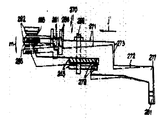
제55도 내지 제57도에 의하면 본 발명에 따른 카세트 테이프 플레이어 테이트 플레이어(70)는 뚜껑(74)의 통로에 대응하는자동 재생 모드 제거 장치(413)를 포함한다. 이 장치(413)는 뒷부분에 인접한 부착판(90)의 아래쪽에 있는 핀(415)에 축을 둔 풀림 레버(415)를 포함하고 있음을 보여준다. 레버(414)의 한끝은 판(90)안에 있는 통로(410)를 통해 위로 돌출하고, 안내 지지대(190)의 아래부분에 있는 구멍안에 삽입되는, 일반적으로 V 형태 부분(414a)을 갖는다. 레버(414)의 반대편 끝은 잠금판이 스프링(384)에 의해 밀리면 잠금판(318)의 활모양의 부분(377)끝의 끝 가장자리(417)에 인접한 합쳐져 맞물리는 부분(414b)을 갖는다. 또, 안내 지지대(190)의 아래 끝 부분에는, 안내 지지대(190)의 합쳐진 한 부분으로써 부착되는 풀림 부품(418)이 있고, 이는 레버(414)의 V형의 위로 향한 부품(414a)에 각을 갖는 면(419)의 반대편에 위치한다.55 to 57, the cassette tape player tate player 70 according to the present invention includes an automatic playback mode removing device 413 corresponding to the passage of the lid 74. As shown in FIG. The device 413 shows a release lever 415 axially located on the pin 415 at the bottom of the attachment plate 90 adjacent to the back. One end of the lever 414 has a generally V-shaped portion 414a that protrudes upward through the passage 410 in the plate 90 and is inserted into a hole in the lower portion of the guide support 190. The opposite end of the lever 414 has a combined engagement portion 414b adjacent the end edge 417 of the end of the bow portion 377 of the locking plate 318 when the locking plate is pushed by the spring 384. In addition, at the lower end of the guide support 190, there is an unlocking part 418 attached as a combined part of the guide support 190, which is angled to the V-upward part 414a of the lever 414. Opposite the side 419 having

제55도에서 보듯이, 풀림 부품(418)은 뚜껑(74)의 수직축에 대해 위치하므로 뚜껑(74)의 움직임은 닫힌 위치에서 열린 위치가 되고, 플림 부품(418)은 점선으로 표시된 위치에서(418')로 표시된 위치로 화살표 Q의 방향인 앞으로 이동하게 된다.As shown in FIG. 55, the unwinding part 418 is located about the vertical axis of the lid 74 so that the movement of the lid 74 is in the closed position in the open position, and the flimmer part 418 is in the position indicated by the dotted line ( 418 ') to move forward in the direction of arrow Q.

앞에 말했듯이, 카세트 테이프 플레이어(70)의 동작에서 카세트(71)는 카세트 홀더가 제9(a)도에 있는 카세트 삽입 위치에 있는 동안 카세트 홀더(75)에 삽입되고, 그후 카세트 홀더(75)는 제9(b)도에 보이는 카세트 장진 위치로 카세트 뚜껑(74)가 함께 수직이동한다.As mentioned before, in the operation of the cassette tape player 70, the cassette 71 is inserted into the cassette holder 75 while the cassette holder is in the cassette insertion position in FIG. 9 (a), and then the cassette holder 75 The cassette lid 74 is vertically moved together to the cassette long position shown in FIG. 9 (b).

카세트 홀더(75)의 이 수직운동은 헤드저부(158)의 끝(158a)을 제34(a)도에 보이는 것처럼 레버(270)의 동작암(277)의 앞에 즉시 이동시킨다. 그후, 제34(b)도에서처럼 재생단추(83)를 누르고 전진된 위치 또는 동작하는 위치에 잠기면, 레버(270)는 모터(211)의 전원을 사용하고 거기 잠기기 위해 전진된 위치에 대해 세로로 이동한다. 레버(270)가 움직이고 있는 동안 동작암(277)은 헤드저부(158)의 끝부분(158a)에서 움직임으로써 동작암은 제34(b)도에 보이는 전진된 위치로 이동하고 필요한 재생 모드를 이루기 위해 그 자리에 머문다. 재생 모드 제거 장치(413)가 없을 경우, 플레이어(70)가 재생 모드에 있는 동안 카세트 뚜껑(74)이 열리면, 즉, 우선 정지 단추(82)를 누르지 않으면, 카세트 장진 위치(제9(b)도)에서 카세트 홀더(75)의 복귀에 의해 수반되는 카세트 삽입 부분(제9(a)도)으로의 카세트 홀더의 수직 이동은 헤드저부의 자유로운 끝부분(158a)을 제58(b)도의 실선으로 표시된 것처럼 레버(270)의 동작암(277)의 위 끝 부분을 향해 갑자기 부딪히게 함으로써, 그 결과로 레버(270)나 헤드(158)가 함께 부서질 것이다.This vertical movement of the cassette holder 75 immediately moves the end 158a of the head bottom 158 in front of the operating arm 277 of the lever 270 as shown in FIG. 34 (a). Then, as shown in FIG. 34 (b), when the regeneration button 83 is pressed and locked in the advanced position or the operating position, the lever 270 uses the power of the motor 211 and runs vertically with respect to the advanced position to be locked there. Move. While the lever 270 is moving, the operating arm 277 moves at the end 158a of the head bottom 158 so that the operating arm moves to the advanced position shown in FIG. 34 (b) and achieves the required regeneration mode. Stay in place. In the absence of the playback mode removing device 413, if the cassette lid 74 is opened while the player 70 is in the playback mode, that is, if the stop button 82 is not pressed first, the cassette holding position (ninth (b)) Vertical movement of the cassette holder to the cassette insertion portion (Fig. 9 (a)) accompanied by the return of the cassette holder 75 in FIG. By suddenly striking toward the upper end of the operating arm 277 of the lever 270, as a result, the lever 270 or the head 158 will be broken together.

또한, 제58(a)도의 실선으로 표시된 재생 모드에서, 카세트 홀더(75)가 점선으로 표시된 카세트 삽입 위치에서 화살표 a의 방향으로 수직 이동하면, 헤드저부(158)의 끝 또는 자유로운 끝부분(158a)은 레버(270)의 동작암(277) 위로 당겨질 것이고, 그에 따라 헤드저부(158)는 점선으로 표시된 전진된 위치로부터 제58(b)도의 실선으로 표시된 원위치 또는 복귀된 위치로 되돌아가도록 스프링(163)에 의해 제13도의 화살표 b의 방향으로 되돌아간다. 그러므로, 카세트 홀더(75)가 제58(b)도의 화살표 a'의 방향으로 수직이동하고 있을때 헤버(270)가 제58(b)도의 실선으로 표시된 것처럼 플레이어의 재생 모드에 해당하는 위치에 계속 있으면, 헤드 저부(158)의 끝 또는 자유로운 끝부분(158a)은 복귀된 위치에서 동작암(277)의 윗부분을 향하여 바로 충돌하게 될 것이다.Further, in the playback mode indicated by the solid line in FIG. 58 (a), when the cassette holder 75 is moved vertically in the direction of the arrow a at the cassette insertion position indicated by the dotted line, the end or free end 158a of the head bottom 158 is moved. ) Will be pulled over the operating arm 277 of the lever 270 so that the head bottom 158 will return from the advanced position indicated by the dotted line to the original position or the returned position indicated by the solid line of FIG. 58 (b). 163), it returns to the direction of arrow b of FIG. Therefore, when the cassette holder 75 is vertically moved in the direction of the arrow a 'in Fig. 58 (b), if the heber 270 continues to be in the position corresponding to the player's playback mode as indicated by the solid line in Fig. 58 (b), The end or free end 158a of the head bottom 158 will collide directly towards the top of the operating arm 277 in the retracted position.

위의 문제는 플레이어(70)에 자동 재생 모드 제거 장치(413)를 가짐으로써 피해진다. 더 나아가서, 카세트 홀더(75)가 제56도에서 실선으로 보인는 카세트 장진 위치로부터 점선으로 카세트 삽입 위치로 화살표 a의 방향을 따라 수직 이동하면, 플림 부품(418)은 제55도와 제57도의 화살표 Q 방향으로 움직이고 레버가 화살표 T의 방향으로 수직 이동한 결과에 따라 레버(414)의 각진 면(419)을 향하여 움직인다.The above problem is avoided by having the player 70 have an automatic playback mode removal device 413. Furthermore, if the cassette holder 75 is moved vertically along the direction of arrow a from the cassette long position shown in solid line in FIG. 56 to the cassette insertion position in dotted line, the flimbing part 418 is arrow Q in FIG. 55 and FIG. Direction and the lever moves toward the angled face 419 of the lever 414 as a result of the vertical movement in the direction of arrow T. FIG.

제55도의 화살표 T의 방향으로의 레버(414)의 수직이동은 맞물린 끝부분(414b)을 잠금판이 스프링(384)의 힘에 의하여 화살표 0'의 방향으로 수직 이동됨으로써 잠금판(418)의 끝부분(417)을 향하여 동작하게 한다.The vertical movement of the lever 414 in the direction of the arrow T in FIG. 55 causes the locking plate to move vertically in the direction of the arrow 0 'by the force of the spring 384 to the engaged end portion 414b. Operate towards portion 417.

앞에 언급했듯이, 잠금판의 이런 수직 이동은 카세트 테이프 플레이어(70)가 자동적으로 정지 모드에 복위함으로써 재생 또는 FWD 단추(83)의 풀림을 야기시킨다. 재생단추(83)의 풀림은 레버(270)를 제58(b)도에 실선으로 표시된 전진된 위치에서 점선으로 보이는 복귀된 또는 원위치로 되돌아가게 함으로써 만일 카세트 홀더(75)가 그후 다시 카세트 장진 위치로 수직 이동하면, 헤드저부(158)의 끝 또는 자유로운 끝부분(158a)은 레버(270)의 암(277)의 앞에 잘 위치하여 암(277)의 위 끝부분을 향하여 절대로 부딪히지 않을 것이다.As mentioned above, this vertical movement of the locking plate causes the cassette tape player 70 to automatically return to the stop mode, causing the playback or FWD button 83 to be released. The release of the play button 83 causes the lever 270 to be returned to the returned or original position shown by the dashed line at the advanced position indicated by the solid line in FIG. 58 (b), so that the cassette holder 75 is thereafter moved back to the cassette long position. Vertically, the end or free end 158a of the head bottom 158 is well positioned in front of the arm 277 of the lever 270 and will never hit towards the upper end of the arm 277.

또한, 자동 재생 모드 제거 장치(413)가 있으므로, 플레이어가 FF 또는 되감기 모드에 있을때 카세트 삽입 위치로의 카세트 홀더(75)의 이동은 잠금판(318)을 제55도의 화살표 0'의 방향으로 수직 이동시키게 되고, 그에 따라 플레이어(70)를 정지 모드로 자동 복귀시키기 위하여 FF 단추(84) 또는 되감기 단추(85)는 풀리게 된다.Also, since there is an automatic playback mode removing device 413, the movement of the cassette holder 75 to the cassette insertion position when the player is in the FF or rewind mode causes the locking plate 318 to be perpendicular to the direction of arrow 0 'in FIG. The FF button 84 or the rewind button 85 is released to automatically move the player 70 back to the stop mode.

또한, 장치(413)가 있기 때문에, 단추(83), (84), (85) 중 어느것도 카세트 뚜껑(74)이 열린 위치에 있는한 눌려진 위치 또는 전진된 위치에서 잠길 수 있다. 본 발명이 카세트 테이프 플레이어에 관한 것이지만, 본 발명은 다른 형태의 기록 또는 재생 장치에 유용하게 쓰여질 수도 있다.In addition, because of the device 413, any of the buttons 83, 84, 85 can be locked in the depressed or advanced position as long as the cassette lid 74 is in the open position. Although the present invention relates to a cassette tape player, the present invention may be usefully used in other types of recording or reproducing apparatus.

첨부된 도면에 따라 본 발명을 자세히 도시하여 설명했지만, 본 발명은 본 장치에만 국한되지 않는다는 것을 알아야 하며, 다양한 변화와 수정이 부록의 요구 사항이 규정하고 있듯이 발명의 영역 또는 정신에서 벗어나지 않고 그 분야의 숙달된 사람에 의하여 실시된 수도 있다.While the invention has been illustrated and described in detail with reference to the accompanying drawings, it should be understood that the invention is not limited to the apparatus, and that various changes and modifications may be made therein without departing from the scope or spirit of the invention as defined by the requirements of the appendix. It may also be conducted by an experienced person.

Claims (1)

반대측에서 상 및 하면을 갖는 직사각형 샤시(76)와, 상기 대향하여 테이프 카세트(71)를 작동하도록 위치시키는 카세트 홀더(75)와, 상기 상면에 대향하여 작동적으로 위치된 테이프 카세트내의 각 릴들을 속박하기 위하여 상기 하면의 측면에서부터 상기 샤시(76)를 통하여 연장된 릴축977, 78)과, 장치의 다수동작 모드에 따라서 상기 축들을 선택적으로 구동하기 위한 테이프 구동 유니트(91)를 포함하는 장치에 있어서, 상기 구동 유니트는 작동 모드중의 하나에서 또다른 하나로 변화하기 위하여 각각이 축 방향으로 변위되는 기어와 함께 상기 하면에 수직이 되는 각 축을 중심으로 회전하도록 하면에 대응하는 상기 샤시의 측면에서 다수의 기어(221, 222, 233, 234, 229, 232)로서 구성되며, 상기 하면에 수직방향으로 연장 및 압축된 위치 사이에서 수동적으로 구동될 수 있으며 하면에 대응하는 샤시의 측면에 각각 배치된 누름 단추(82내지 85)와, 각 축들을 상기 방향으로 기어를 변위시키므로서 장치의 작동 모드를 바꾸게 하기 위하여 연장된 위치에서 압압된 누름단추의 작동에 응답하는 동작판(245, 248)으로 구성되는 것을 특징으로 하는 카세트 테이프 기록재생장치.A rectangular chassis 76 having an upper and a lower surface on the opposite side, a cassette holder 75 for positioning the tape cassette 71 opposing the opposing surface, and respective reels in the tape cassette operatively positioned opposite the upper surface. A reel shaft 997, 78 extending through the chassis 76 from the side of the lower surface for confinement and a tape drive unit 91 for selectively driving the shafts in accordance with the multi-operation mode of the apparatus. Thus, the drive unit has a plurality of sides on the side of the chassis corresponding to the lower surface such that the drive unit rotates about each axis perpendicular to the lower surface with gears displaced in the axial direction to change from one of the operating modes to another. Gears 221, 222, 233, 234, 229, and 232, and between the extended and compressed positions perpendicular to the lower surface. Pushbuttons 82 to 85, each of which can be driven and disposed on the side of the chassis corresponding to the lower surface, and pressed in an extended position to change the operating mode of the device by displacing the gears in the respective directions in the respective axes; A cassette tape recording and reproducing apparatus, comprising: operation plates (245, 248) that respond to operation of a button.
KR1019810005292A 1980-12-29 1981-12-29 Cassette tape resording and reproducing apparatus KR880001468B1 (en)

Applications Claiming Priority (3)

Application Number Priority Date Filing Date Title
JP55-188031 1980-12-29
JP188031 1980-12-29
JP55188031A JPS57113449A (en) 1980-12-29 1980-12-29 Tape driver

Publications (2)

Publication Number Publication Date
KR830008307A KR830008307A (en) 1983-11-18
KR880001468B1 true KR880001468B1 (en) 1988-08-11

Family

ID=16216447

Family Applications (3)

Application Number Title Priority Date Filing Date
KR1019810005291A KR880001467B1 (en) 1980-12-29 1981-12-29 A cassette tape, recording and reproducting apparatus
KR1019810005292A KR880001468B1 (en) 1980-12-29 1981-12-29 Cassette tape resording and reproducing apparatus
KR1019810005289A KR880001461B1 (en) 1980-12-29 1981-12-29 Mode changeing mecharnism for cassette tape player

Family Applications Before (1)

Application Number Title Priority Date Filing Date
KR1019810005291A KR880001467B1 (en) 1980-12-29 1981-12-29 A cassette tape, recording and reproducting apparatus

Family Applications After (1)

Application Number Title Priority Date Filing Date
KR1019810005289A KR880001461B1 (en) 1980-12-29 1981-12-29 Mode changeing mecharnism for cassette tape player

Country Status (11)

Country Link
US (4) US4453189A (en)
JP (1) JPS57113449A (en)
KR (3) KR880001467B1 (en)
AT (4) AT374030B (en)
AU (3) AU547005B2 (en)
BR (4) BR8108437A (en)
CA (4) CA1188415A (en)
DE (4) DE3151715A1 (en)
ES (4) ES508373A0 (en)
FR (4) FR2497383B1 (en)
GB (4) GB2092808B (en)

Families Citing this family (31)

* Cited by examiner, † Cited by third party
Publication number Priority date Publication date Assignee Title
JPS58212644A (en) * 1982-06-04 1983-12-10 Toshiba Corp Tape recorder device
JPS5963842U (en) * 1982-07-16 1984-04-26 日本ビクター株式会社 Tape recorder quick review operation mechanism
JPS5928827U (en) * 1982-08-13 1984-02-22 日本ビクター株式会社 Magnetic head azimuth adjustment mechanism
US4646186A (en) * 1982-09-14 1987-02-24 Alps Electric Co., Ltd. Cassette tape recorder with plural tape guide structure
DE3382038D1 (en) * 1982-10-01 1991-01-10 Toshiba Kawasaki Kk CASSETTE DEVICE AND TAPE DRIVE.
EP0191361B1 (en) * 1982-10-01 1990-11-28 Kabushiki Kaisha Toshiba Apparatus for transporting tape in a cassette
DE3346893A1 (en) * 1982-12-23 1984-06-28 Clarion Co., Ltd., Tokio/Tokyo Magnetic tape apparatus
JPS59144089A (en) * 1983-02-08 1984-08-17 Sony Corp Cassette tape player with radio set
US4649453A (en) * 1983-02-08 1987-03-10 Sony Corporation Cassette tape player having sealing means
JPS59189703U (en) * 1983-06-03 1984-12-15 ソニー株式会社 cassette tape recorder
JPS6028057A (en) * 1983-07-27 1985-02-13 Sony Corp Tape recorder
JPS6026642U (en) * 1983-07-30 1985-02-22 ソニー株式会社 Tape recorder mode switching mechanism
JPS6066352A (en) * 1983-09-20 1985-04-16 Sony Corp Reverse type tape recorder
JPS60194793U (en) * 1984-06-01 1985-12-25 ソニー株式会社 cassette tape recorder
US4703372A (en) * 1985-03-08 1987-10-27 Spacelabs, Inc. Portable electrocardiographic recorder
JPH0831233B2 (en) * 1985-03-27 1996-03-27 株式会社日立製作所 Cassette holder
JPH07122981B2 (en) * 1985-09-03 1995-12-25 ソニー株式会社 Cassette tape recorder
AT390153B (en) * 1988-06-14 1990-03-26 Philips Nv RECORDING AND / OR REPLAYING DEVICE FOR A TAPE-SHAPED RECORDING CARRIER
JPH0265246U (en) * 1988-10-31 1990-05-16
US5144507A (en) * 1989-04-27 1992-09-01 Sony Corporation Cassette tape recording and/or reproducing apparatus with a single pinch lever assembly
JP2669048B2 (en) * 1989-04-27 1997-10-27 ソニー株式会社 Tape recorder
EP0395299B1 (en) * 1989-04-28 1995-11-15 Sony Corporation Drive means for recording and/or reproducing apparatus
EP0530700A2 (en) * 1991-08-30 1993-03-10 Matsushita Electric Industrial Co., Ltd. A cassette tape mount for use in a cassette tape recorder
DE4236179A1 (en) * 1992-10-27 1994-04-28 Philips Patentverwaltung Technical device, in particular electromechanical drive for moving information carriers
IT1267038B1 (en) * 1993-04-28 1997-01-24 So Ge Mi Spa RECORDED MAGNETIC TAPE REPRODUCER APPARATUS, USING "SOFT TOUCH" MECHANICS IN WHICH A SINGLE ELECTRIC MOTOR PERFORMS
GB2307775B (en) * 1995-11-28 1999-11-24 Daewoo Electronics Co Ltd Reel driving apparatus for a video cassette recorder and method for preventing malfunction thereof
JP2003036627A (en) * 2001-07-23 2003-02-07 Fuji Photo Film Co Ltd Recording tape cartridge
ATE525647T1 (en) * 2006-06-27 2011-10-15 Hoffmann La Roche DIAGNOSTIC TAPE CASSETTE
GB2475053A (en) * 2009-11-03 2011-05-11 Lucima Pty Ltd Programmable sound player and recorder
USD967925S1 (en) * 2019-03-21 2022-10-25 Mahle International Gmbh End plate for a filter element
USD967926S1 (en) * 2019-03-21 2022-10-25 Mahle International Gmbh End plate for a filter element

Family Cites Families (41)

* Cited by examiner, † Cited by third party
Publication number Priority date Publication date Assignee Title
FR1388831A (en) * 1963-12-18 1965-02-12 Advanced pocket tape recorder
DE1261331B (en) * 1965-11-24 1968-02-15 Grundig Emv Small tape recorder
DE1572472B2 (en) * 1966-09-08 1976-07-08 Matsushita Electric Industrial Co., Ltd., Kadoma, Osaka (Japan) TAPE RECORDER WITH PUSH BUTTONS
DE1572528A1 (en) * 1967-09-28 1970-03-05 Telefunken Patent Push button switch for magnetic recorders
US3922719A (en) * 1967-12-29 1975-11-25 Clarion Co Ltd Playing method of tape player and an equipment thereof
GB1210908A (en) * 1968-07-17 1970-11-04 Ricoh Kk Improvements in and relating to film projectors
DE1921343B1 (en) * 1969-04-26 1970-07-30 Grundig Emv Magnetic tape recorder
US3627185A (en) * 1970-01-05 1971-12-14 Scanfax Systems Corp Tape recording system mechanism
DE2064618A1 (en) * 1970-12-30 1972-07-20 Sued Atlas Werke Gmbh Magnetic sound device, in particular with magnetic tape cassettes that can be plugged onto drive shafts that are fixed to the device
DE2138260A1 (en) * 1971-07-30 1973-02-08 Compur Werk Gmbh & Co TAPE RECEIVER
DE2151148A1 (en) * 1971-10-14 1973-04-19 Grundig Emv MAGNETIC TAPE DEVICE, IN PARTICULAR FOR CASSETTE OPERATION
US3800323A (en) * 1972-03-24 1974-03-26 Int Tapetronics Corp Cassette tape transport with pivotally supported universally adjustable head and upright front-mounted cassette
FI61583C (en) * 1972-04-21 1982-08-10 Compur Electronic Gmbh MAGNETOFON
JPS5148044B2 (en) * 1973-03-21 1976-12-18
IT1004252B (en) * 1974-04-05 1976-07-10 Autovox Spa KINEMATISM FOR RIBBONS IN PARTICULAR FOR CARTRIDGE BELTS
US3978522A (en) * 1974-06-14 1976-08-31 Teletype Corporation Method and apparatus for mounting a cassette record-playback head
US3909845A (en) * 1974-06-14 1975-09-30 Teletype Corp Apparatus and method for sensing the condition of a tape within a tape cassette
GB1528902A (en) * 1974-10-01 1978-10-18 Racal Zonal Cassettes Ltd Recording tape transport machine
US3976263A (en) * 1974-10-29 1976-08-24 Technical Incorporated Operating system in a magnetic tape reproducer and recorder
GB1508639A (en) * 1974-12-10 1978-04-26 Matsushita Electric Ind Co Ltd Push rod type tape recorder operating device
FR2305822A1 (en) * 1975-03-28 1976-10-22 Erji Magnetic recording unit for digital information - uses hinged cassette support system incorporating recording head
GB1548664A (en) * 1975-06-24 1979-07-18 Matsushita Electric Ind Co Ltd Magnetic tape recording and reproducing system
US4037262A (en) * 1975-07-16 1977-07-19 Olympus Optical Co., Ltd. Solenoid operated transcriber mechanism
IT1056114B (en) * 1975-09-10 1982-01-30 Deneb Sa DRIVING KINEMATISM FOR GIRANASTRI AND SIMILAR
DE2709070A1 (en) * 1976-03-04 1977-09-08 Olympus Optical Co Small magnetic tape cassette recorder - has fold away hinged stand to allow unit to be supported on flat surface with chosen inclination
JPS52140307U (en) * 1976-04-17 1977-10-24
NL7606690A (en) * 1976-06-21 1977-12-23 Philips Nv MAGNET BDNDCASSETTE DEVICE.
US4116078A (en) * 1976-06-23 1978-09-26 Trio Kabushiki Kaisha Lock release mechanism for push button levers in a tape recorder
SU581504A1 (en) * 1976-07-12 1977-11-25 Специальное Проектно-Конструкторское И Технологическое Бюро Малых Электрических Машин Объединения "Эльфа" Tape-driving mechanism of magnetic recording apparatus
JPS5351713A (en) * 1976-10-20 1978-05-11 Matsushita Electric Ind Co Ltd Magnetic recording and reproducing system
SU637855A1 (en) * 1977-05-03 1978-12-15 Специальное Проектно-Конструкторское И Технологическое Бюро Малых Электрических Машин Объединения "Эльфа" Device for switching-over magnetic tape speed
JPS53140007A (en) * 1977-05-13 1978-12-06 Hitachi Ltd Power transmission system for cassette tape recorder
JPS6020815B2 (en) * 1977-08-22 1985-05-23 ソニー株式会社 Mode selection mechanism in recording/playback equipment
JPS5953618B2 (en) * 1977-09-12 1984-12-26 ソニー株式会社 Mode switching mechanism of recording/playback device
DE2743137A1 (en) * 1977-09-24 1979-04-05 Dual Gebrueder Steidinger Drive system for tape recorder - has two driving wheels for fast rewind, and further, small wheel driven through friction coupling and driving winding reel
US4158212A (en) * 1978-03-30 1979-06-12 Motorola, Inc. Magnetic tape head azimuth assembly
JPS6021413B2 (en) * 1978-12-29 1985-05-27 ソニー株式会社 Operation switching device for tape recorders, etc.
JPS615642Y2 (en) * 1979-01-31 1986-02-20
US4257075A (en) * 1979-03-23 1981-03-17 Minnesota Mining And Manufacturing Company Tape magazine and recording and/or playback machine with improved magazine locating and loading structure
JPS5718043A (en) * 1980-07-08 1982-01-29 Clarion Co Ltd Tape player
US4430680A (en) * 1980-09-30 1984-02-07 Clarion Co., Ltd. Reciprocating member control mechanism in tape player

Also Published As

Publication number Publication date
BR8108435A (en) 1982-10-13
AT374948B (en) 1984-06-12
AU547005B2 (en) 1985-10-03
DE3151716C2 (en) 1990-07-05
AT374027B (en) 1984-03-12
AT374031B (en) 1984-03-12
DE3151716A1 (en) 1982-11-04
GB2091024A (en) 1982-07-21
FR2497383A1 (en) 1982-07-02
ES8303785A1 (en) 1983-02-01
ES8306908A1 (en) 1983-06-01
KR880001461B1 (en) 1988-08-10
GB2090694A (en) 1982-07-14
ES508372A0 (en) 1983-02-01
GB2090694B (en) 1985-05-22
US4491287A (en) 1985-01-01
AU7882081A (en) 1982-07-15
ES508373A0 (en) 1983-02-01
CA1188414A (en) 1985-06-04
FR2497381B1 (en) 1986-11-14
FR2497384A1 (en) 1982-07-02
US4453189A (en) 1984-06-05
AT374030B (en) 1984-03-12
AU7881781A (en) 1982-07-08
GB2091024B (en) 1985-06-12
GB2092808A (en) 1982-08-18
AU546362B2 (en) 1985-08-29
JPS57113449A (en) 1982-07-14
JPS6242342B2 (en) 1987-09-08
ATA560381A (en) 1983-07-15
KR830008304A (en) 1983-11-18
FR2497382A1 (en) 1982-07-02
ES508371A0 (en) 1983-06-01
DE3151710C2 (en) 1992-10-15
DE3151715C2 (en) 1990-09-27
DE3151711C2 (en) 1992-10-08
GB2092808B (en) 1984-11-07
FR2497384B1 (en) 1986-04-11
AU7881881A (en) 1982-07-08
KR830008306A (en) 1983-11-18
BR8108437A (en) 1982-10-19
CA1188415A (en) 1985-06-04
CA1188417A (en) 1985-06-04
FR2497383B1 (en) 1986-09-12
AU540824B2 (en) 1984-12-06
ES8303786A1 (en) 1983-02-01
ATA560981A (en) 1983-10-15
ES508370A0 (en) 1983-02-01
BR8108436A (en) 1982-10-13
DE3151715A1 (en) 1982-08-12
BR8108438A (en) 1982-10-19
FR2497382B1 (en) 1986-04-11
ATA561081A (en) 1983-07-15
KR830008307A (en) 1983-11-18
KR880001467B1 (en) 1988-08-11
FR2497381A1 (en) 1982-07-02
US4511941A (en) 1985-04-16
ATA560881A (en) 1983-07-15
DE3151710A1 (en) 1982-08-12
GB2090459A (en) 1982-07-07
ES8303783A1 (en) 1983-02-01
GB2090459B (en) 1984-09-26
US4542431A (en) 1985-09-17
CA1188416A (en) 1985-06-04
DE3151711A1 (en) 1982-08-12

Similar Documents

Publication Publication Date Title
KR880001468B1 (en) Cassette tape resording and reproducing apparatus
JPH033294B2 (en)
US5764433A (en) Short-side-loading tape cassette recording and/or reproducing apparatus
KR880001469B1 (en) Tape transport mechanism for cassette tape player
US4227226A (en) Cassette tape player
JPS6120675Y2 (en)
JPS6125095Y2 (en)
JPS6120703Y2 (en)
JPS6349296B2 (en)
JPS595975B2 (en) Recording disc playback device
JPS6125074Y2 (en)
JPS6120704Y2 (en)
JPS6131540B2 (en)
JPS647415B2 (en)
JP4132096B2 (en) Recording and / or playback device
JP3900190B2 (en) Recording and / or reproducing apparatus using a tape cassette
JP3039063B2 (en) Tape slack winding mechanism
JPS5813476Y2 (en) Tape recorder operating lever device
JPH0344393B2 (en)
JPH079233Y2 (en) Tape cassette loading device
JPS6029107Y2 (en) cassette tape recorder
KR200154257Y1 (en) A function inferiority prevention structure of loading rack for vcr
JPH0817102A (en) Driving force-transmitting/switching mechanism and tape player apparatus
JPS58108056A (en) Cassette loader
JPS6131538B2 (en)