KR860001833B1 - Apparatus for dimensioning slide fastener coupling elements - Google Patents
Apparatus for dimensioning slide fastener coupling elements Download PDFInfo
- Publication number
- KR860001833B1 KR860001833B1 KR1019850002887A KR850002887A KR860001833B1 KR 860001833 B1 KR860001833 B1 KR 860001833B1 KR 1019850002887 A KR1019850002887 A KR 1019850002887A KR 850002887 A KR850002887 A KR 850002887A KR 860001833 B1 KR860001833 B1 KR 860001833B1
- Authority
- KR
- South Korea
- Prior art keywords
- compactor
- roll
- presser
- coupling elements
- disk
- Prior art date
Links
Images


Classifications
-
- A—HUMAN NECESSITIES
- A44—HABERDASHERY; JEWELLERY
- A44B—BUTTONS, PINS, BUCKLES, SLIDE FASTENERS, OR THE LIKE
- A44B19/00—Slide fasteners
- A44B19/02—Slide fasteners with a series of separate interlocking members secured to each stringer tape
-
- B—PERFORMING OPERATIONS; TRANSPORTING
- B29—WORKING OF PLASTICS; WORKING OF SUBSTANCES IN A PLASTIC STATE IN GENERAL
- B29D—PRODUCING PARTICULAR ARTICLES FROM PLASTICS OR FROM SUBSTANCES IN A PLASTIC STATE
- B29D5/00—Producing elements of slide fasteners; Combined making and attaching of elements of slide fasteners
-
- Y—GENERAL TAGGING OF NEW TECHNOLOGICAL DEVELOPMENTS; GENERAL TAGGING OF CROSS-SECTIONAL TECHNOLOGIES SPANNING OVER SEVERAL SECTIONS OF THE IPC; TECHNICAL SUBJECTS COVERED BY FORMER USPC CROSS-REFERENCE ART COLLECTIONS [XRACs] AND DIGESTS
- Y10—TECHNICAL SUBJECTS COVERED BY FORMER USPC
- Y10S—TECHNICAL SUBJECTS COVERED BY FORMER USPC CROSS-REFERENCE ART COLLECTIONS [XRACs] AND DIGESTS
- Y10S425/00—Plastic article or earthenware shaping or treating: apparatus
- Y10S425/034—Morin
-
- Y—GENERAL TAGGING OF NEW TECHNOLOGICAL DEVELOPMENTS; GENERAL TAGGING OF CROSS-SECTIONAL TECHNOLOGIES SPANNING OVER SEVERAL SECTIONS OF THE IPC; TECHNICAL SUBJECTS COVERED BY FORMER USPC CROSS-REFERENCE ART COLLECTIONS [XRACs] AND DIGESTS
- Y10—TECHNICAL SUBJECTS COVERED BY FORMER USPC
- Y10S—TECHNICAL SUBJECTS COVERED BY FORMER USPC CROSS-REFERENCE ART COLLECTIONS [XRACs] AND DIGESTS
- Y10S425/00—Plastic article or earthenware shaping or treating: apparatus
- Y10S425/814—Zipper
Landscapes
- Engineering & Computer Science (AREA)
- Mechanical Engineering (AREA)
- Slide Fasteners (AREA)
- Press Drives And Press Lines (AREA)
Abstract
Description
제 1 도는 본 발명의 실시예의 따른 치수 조정 장치의 부분단면 정면도.1 is a partial cross-sectional front view of a dimensional adjustment device according to an embodiment of the present invention.
제 2 도는 슬라이드 파스너 결합 요소들을 성형하는 장치에 통합된 제 2 도의 치수 조정 장치의 개략적인 측면도.2 is a schematic side view of the dimension adjusting device of FIG. 2 integrated into an apparatus for forming slide fastener coupling elements.
제 3 도는 제 1 도에 도시된 치수 조정 장치에 있는 제 1 및 제 2 압착기 로울들의 확대된 부분 사시도.3 is an enlarged partial perspective view of the first and second compactor rolls in the dimensional adjustment device shown in FIG.
제 4a도는 슬라이드 파스너 결합 요소 블랭크(blank)의 확대된 부분 평면도.4A is an enlarged fragmentary plan view of a slide fastener coupling element blank.
제 4b도는 제 4a도에 도시된 슬라이드 파스너 결합 요소 블랭크의 확대된 부분 측면도.4B is an enlarged partial side view of the slide fastener coupling element blank shown in FIG. 4A.
제 4c도는 제 4a도의 블랭크로 부터 형성된 슬라이드 파스너 결합 요소 조립체의 확대된 부분 평면도.4C is an enlarged fragmentary plan view of the slide fastener coupling element assembly formed from the blank of FIG. 4A.
제 4d도는 제 4c도의 슬라이드 파스너 결합 요소의 확대된 측면도.4d is an enlarged side view of the slide fastener coupling element of FIG. 4c.
제 4e도는 제 4c도의 슬라이드 파스너 결합 요소 조립체가 있는 슬라이드 파스너 스트링어의 확대된 부분 평면도.4E is an enlarged partial plan view of the slide fastener stringer with the slide fastener coupling element assembly of FIG. 4C.
제 5a도는 다른 슬라이드 파스너 결합 요소 블랭크의 확대된 부분 평면도.5A is an enlarged partial plan view of another slide fastener coupling element blank.
제 5b도는 제 5a도에 도시된 슬라이드 파스너 결합 요소 블랭크의 확대 측면도.FIG. 5B is an enlarged side view of the slide fastener coupling element blank shown in FIG. 5A.
제 5c도는 제 5a도의 블랭크로 부터 형성된 슬라이드 파스너 결합 요소 조립체의 확대된 부분 평면도.5C is an enlarged fragmentary plan view of the slide fastener coupling element assembly formed from the blank of FIG. 5A.
제 5d도는 제 5c도의 슬라이드 파스너 결합 요소 조립체의 확대된 측면도.FIG. 5D is an enlarged side view of the slide fastener coupling element assembly of FIG. 5C.
제 5e도는 제 5c도의 슬라이드 파스너 결합 요소 조립체가 달린 슬라이드 파스너 스트링어의 확대된 부분 평면도.FIG. 5E is an enlarged fragmentary plan view of the slide fastener stringer with the slide fastener coupling element assembly of FIG. 5C.
제 6a도는 또 다른 슬라이드 파스너 결합요소 조립체가 달린 슬라이드 파스너 스트링어의 확대된 부분 평면도.6A is an enlarged fragmentary plan view of a slide fastener stringer with another slide fastener coupling element assembly.
제 6b도는 제 6a도에 도시된 슬라이드 파스너 스트링어의 확대된 횡단면도.FIG. 6B is an enlarged cross sectional view of the slide fastener stringer shown in FIG. 6A.
제 7 도는 제 1 도의 장치에 있는 압착기 로울들이 제 4d도에 도시된 슬라이드 파스너 결합 요소를 치수조정 하도록 작동할 때에 압착기 로울들의 확대된 부분 단면도.7 is an enlarged partial cross-sectional view of the compactor rolls when the compactor rolls in the apparatus of FIG. 1 operate to dimension the slide fastener coupling element shown in FIG. 4d.
제 8 도는 제 7도에 도시된 압착기 로울들이 서로 떨어져 있을 때에 압착기 로울들의 확대된 부분 단면도.FIG. 8 is an enlarged partial cross sectional view of the compactor rolls when the compactor rolls shown in FIG.
제 9 도는 제 7 도의 Ⅸ-Ⅸ선을 따라 취한 단면도.9 is a cross-sectional view taken along the line VII-VII of FIG. 7.
제10도는 본 발명의 다른 실시예에 따른 압착기 로울들의 확대된 부분 단면도.10 is an enlarged partial cross-sectional view of the compactor rolls in accordance with another embodiment of the present invention.
제11도는 본 발명의 또 다른 실시예에 따른 압착기 로울들의 확대된 부분 단면도.11 is an enlarged partial cross-sectional view of the compactor rolls according to another embodiment of the present invention.
제12도는 본 발명의 또 다른 실시예에 따른 압착기 로울들의 확대된 단면도.12 is an enlarged cross-sectional view of the compactor rolls according to another embodiment of the present invention.
* 도면의 주요부분에 대한 부호의 설명* Explanation of symbols for main parts of the drawings
16 : 기부 17 : 제 1 축16: donation 17: first axis
20 : 제 2 축 18, 88, 90, 100 : 제 1 압착기 로울20:
34, 86, 91, 102 : 제 1압착기 표면 3, 101 : 스퍼어 기어34, 86, 91, 102: first presser surface 3, 101: spur gear
24, 89, 92, 103 : 제 2 압착기 로울 39, 87, 93, 104 : 제 2 압착기 표면24, 89, 92, 103:
40 : 단부표면 41, 105 : 핀 기어40:
64, 74, 83, 111 : 결합 요소 68, 69, 76, 77 : 다리64, 74, 83, 111:
42 : 핀 이들 47 : 분할 융기부42: pin these 47: split ridge
30, 36 : 제 1 디스크 50, 107 : 제 3 압착기 표면30, 36:
52 : 제 3 축 31, 37 : 제 2 디스크52:
본 발명은 합성수지 혹은 금속제의 개별 슬라이드 파스너 결합 요소들을 치수 조정하는 장치에 관한 것이다.The present invention relates to an apparatus for dimensioning individual slide fastener coupling elements made of synthetic resin or metal.
슬라이드 파스너 요소들을 장착하거나 합성수지제의 슬라이드 결합 요소들을 형성하는 장치에서 슬라이드 파스너 결합 요소들을 치수 조정하기 위한 장치는 공지되어있다. 한가지 공지된 치수 조정장치는 1967년 1월 28일자 특허된 일본특허 공고 소42-1939에 나타낸 바와 같은 1쌍의 압착기 로울들을 포함한다. 1983년 10월 27일자 특허된 미합중국 특허 제4, 406, 849호는 압착기 휘일 및 압착기 다이를 가진 다른 치수조정장치를 나타낸다. 압착기 로울 혹은 압착기 휘일은 스퍼어 기어 혹은 베벨 기어와 같은 일련의 보통 기어들을 통해 구동된다.Apparatuses for dimensioning slide fastener coupling elements in a device for mounting slide fastener elements or for forming slide coupling elements made of resin are known. One known dimensional adjusting device includes a pair of compactor rolls as shown in Japanese Patent Publication No. 42-1939, filed Jan. 28, 1967. United States Patent Nos. 4, 406, 849, filed October 27, 1983, show another dimensioning device having a compactor wheel and a compactor die. The compactor roll or compactor wheel is driven through a series of ordinary gears such as spur gears or bevel gears.
슬라이드 파스너 결합 요소들에 성형될 소망의 치수들을 조정 하거나 변화시킬 필요가 있는 때, 압착기 로울 혹은 압차기 휘일의 회전축을 횡운동시키는 것이 통례였다. 그러나 회전축의 운동은 교합기어 이들을 서로 멀어지게 혹은 가까워지게 변위시킴으로써 기어 이들사이에 역회전 혹은 지나친 강제 맞물림을 일으킨다. 그러므로, 압차기 로울 혹은 압착기 휘일들은 다른 회전 부품과 동기적으로 회전하지 못하게 되거나, 부드럽게 회전하기 못하게된다. 또한 종래 치수 조정장치는 조정의 범위가 작고 슬라이드 파스너 결합 요소들이 쉽게 제자리에 고정될 수 없다는 점에서 불리하다.When it is necessary to adjust or change the desired dimensions to be molded to the slide fastener coupling elements, it has been customary to transverse the axis of rotation of the compactor roll or the presser wheel. However, the movement of the axis of rotation causes the occlusal gears to move away from or close to each other, causing reverse rotation or excessive force engagement between them. Therefore, the presser rolls or the presser wheels may not rotate synchronously with other rotating parts or may not rotate smoothly. Conventional dimensional adjusters are also disadvantageous in that the range of adjustment is small and the slide fastener coupling elements cannot be easily fixed in place.
본 발명의 목적은, 슬라이드 파스너 결합 요소의 치수 조정장치로서 폭 및 길이와 소망의 치수들로 결합요소들을 정확히 성형하기 위한 위치 조정 가능한 로울 수단을 가진 장치를 제공하는 것이다.It is an object of the present invention to provide an apparatus with positionable roll means for precisely forming the engaging elements with width and length and the desired dimensions as the dimensional adjusting device of the slide fastener engaging element.
본 발명의 목적은, 슬라이드 파스너 결합 요소들을 치수 조정하는 장치로서 결합 요소들을 흠내거나 손상시키지 않고서 치수조정하도록 결합 요소들에 걸리면서 동기적으로 부드럽게 회전 가능하고 위치 조절 가능한 압착기 로울들을 가진 장치를 제공하는 것이다.SUMMARY OF THE INVENTION An object of the present invention is to provide an apparatus for dimensioning slide fastener coupling elements, the apparatus having squeezer rolls that are synchronously smoothly rotatable and adjustable while being hung on the coupling elements to dimension them without scratching or damaging the coupling elements. will be.
본 발명의 또 다른 목적은, 소망의 간격 혹은 피치들로 다리들이 떨어져 위치되도록 결합 요소들이 위치적으로 변위되는 것을 방지하기 위한 수단을 가진 치수조정 로울러들을 포함하는 결합 요소 치수 조정장치를 제공하는 것이다.It is a further object of the present invention to provide a coupling element sizing device comprising dimensioning rollers with means for preventing the coupling elements from being displaced positionally so that the legs are positioned apart at the desired spacing or pitch. .
본 발명에 따르면, 1열의 슬라이드 파스너 요소들을 치수 조정하는 장치는 결합 요소들의 다리들에 걸리도록 제 1 및 제 2 대향 압착기 표면들을 각가 가진 1쌍의 제 1 및 제 2압착기 로울들을 포함한다. 제 1 및 제 2 압착기 표면들은 그 사이에 결합 요소들을 위치 조정하기 위한 최근접 대향 부분들을 가지며, 그 최근접 대향 부분들은 결합 요소들의 회측 표면들 사이에서 각 결합 요소의 폭과 동일한 제 1 거리만큼 서로 떨어져 있다. 제 2 압착기 로울은 제 1 거리를 변화시키도록 제 1 압착기 로울에 때해 변위될 수 있다. 제 1 압착기 로울은 제 2 압착기 로울위의 핀 기어와 맛물려 보유되는 스피어 기어를 가진다. 제 1 및 제 2압착기로울들은 제 2 압착기 로울이 제 1 압착기 로울에 대해 상대적으로 변위된 때라도 스피어 기어와 핀 기어의 교합을 통해 동기적으로 회전 될 수 있다. 제 1 및 제 2 압착기 로울들은 또한 다리들이 등간격으로 떨어져 유지되도록 다리들과 맛물리는 분할 융기부들을 가진다. 제 1 및 제 2 압착기 로울들 중하나는 결합 요소의 결합헤드들과 걸리는 제 3 압착기 표면을 가진다. 다른 압착기 로울은 제 3 압착기 표면을 향햐 결합 요소들을 압압하도록 제 3 압착기 표면과 마주보는 제 4 압착기 표면을 가진다. 제 3 및 제 4 압착기 표면들은 사이에서 결합 요소들을 위치 조정하는 최근접 대향 부분들을 가지고, 최근접 대향 부분들은 결합헤드 끝과 다리 끝들 사이의 각 결합 요소 길이와 동일한 제 2 거리 만큼 서로 떨어져 있다. 제4압착기 표면이 있는 압착기 로울은 제 1 압착기 로울에 대해 변위될 수 있어 제 2 거리를 변화시킨다.According to the present invention, an apparatus for dimensioning a row of slide fastener elements includes a pair of first and second compactor rolls each having first and second opposing compactor surfaces to engage the legs of the coupling elements. The first and second presser surfaces have the nearest opposing parts for positioning the coupling elements therebetween, the closest opposing parts having a first distance equal to the width of each coupling element between the abutment surfaces of the coupling elements. Away from each other. The second compactor roll may be displaced relative to the first compactor roll to change the first distance. The first compactor roll has a pin gear on the second compactor roll and a spear gear retained tasting. The first and second compactors can be rotated synchronously through the engagement of the spear gear and the pin gear even when the second compactor roll is displaced relative to the first compactor roll. The first and second compactor rolls also have split ridges that are tasting with the legs so that the legs remain apart at equal intervals. One of the first and second compactor rolls has a third compactor surface that engages with the coupling heads of the coupling element. The other compactor roll has a fourth compactor surface facing the third compactor surface to press the coupling elements facing the third compactor surface. The third and fourth presser surfaces have the nearest opposing portions that position the coupling elements therebetween, the closest opposing portions being spaced from each other by a second distance equal to the length of each coupling element between the coupling head end and the leg ends. The compactor roll with the fourth compactor surface may be displaced relative to the first compactor roll to change the second distance.
이하, 첨부된 도면을 참조하여 본 발명의 특징 및 잇점들을 더욱 상세히 설명한다.Hereinafter, with reference to the accompanying drawings will be described in more detail the features and advantages of the present invention.
본 발명의 원리들은 제 1 도에 대개(10)으로 표시된, 슬라이드 파스너 결합 요소의 치수 조정장치에 구현될 때 특히 유리하다.The principles of the present invention are particularly advantageous when implemented in the dimensioning device of the slide fastener coupling element, which is indicated generally at 10 in FIG. 1.
제 2 도에 도시된 바와 같이, 치수 조정장치(10)는 합성수지의 슬라이드 파스너 결합 요소를 형성하는 장치(11)에 결합된다. 치수 조정장치(10)는 성형된 결합 요소들의 배출로를 따라 장치(11)의 배출단부에 배치된 두개의 유니트(10A, 10B)를 포함한다. 치수 조정장치(10)는, 성형된 결합 요소들이 요구된 치수들로 성형된 후에 탄성복귀되는 경향을 갖지 않으면 하나의 유니트만을 가질 수 있다.As shown in FIG. 2, the
두 유니트들(10A)(10B)이 구조상 동일하므로, 이하 그 중 하나만 설명될 것이다. 제 1 도에 도시된 바와 같이, 슬라이드 파스너 결합 요소 형성장치(11)는 프레임(12)을 가지고, 아암(15)에 연결된 지지봉(13, 14)이 그 프레임(12)위에 장착된다. 아암(15)에 고정된 브라켓 혹은 기부(16)위에 제 1 수평축(17)이 회전 가능하게 지지된다. 제 1 압착기 로울(18)은 제 1축(17)위에 1쌍의 로울러 베어링(19)에 의해 회전가능하게 장착된다.Since the two
제 2 수직축(20)은 1쌍의 보울 베어링(23)에 의해 슬라이드 블록(21)위에 회전가능하게 장착되고 슬리이브(22)로 덮여있다. 슬라이드 블록(21)은 제 1 수평축(17)의 축방향으로 미끄럼 운동하는 브라켓(16)위에 장착된다. 제 3 도에 도시된 대로, 제 1 수평축(17)과 제 2 수직축(20)은 공통평면에서 연장하고, 서로 수직하게 연장하는 각 중심축 X-X, Y-Y를 가진다. 제 2 압착기 로울(24)은 볼트(25)에 의해 제 2 수직출(20)의 축방향 단부에 고정되고, 워셔(26)가 볼트(25)와 제 2 압착기 로울(24) 사이에 끼워진다. 슬라이드 블록(21)위에 회전가능하게 장착된 나사봉(27)은 브라켓(16)에 마련된 내부나사진 구멍(28)에 나사고정되고, 나사봉(27)은 제 1 수평축(19)에 평행한 축선을 가진다. 나사봉(27)을 돌려 축방향으로 이동시키으로써, 슬라이드 블록(21) 및 제 2 수직축(20)은 화살 A, B 방향으로 제 1수평축(17)에 멀리 또 가까이 이동될 수 있다. 나사봉(27)은 고정너트(29)에 의해 브라켓(16)에 대해 정위치에 고정될 수 있다.The second
제 3 도에 예시된 대로, 제 1 압착기 로울(18)은 1쌍의 볼트(32)에 의해 동심원적으로 함께 고정된 제 1 디스크 혹은 휘일(30)과 제 2 디스크 혹은 휘일(31)로 되어 있다. 제 1 압착기 로울(18)은 그 원주연부에서 제 2수직축(20)을 향하는 환상 요홈부(33)을 가진다. 환상 요홈부(33)는 제 1 디스크(30)의 단면이 L형 벽과 제 2 디스크(31)로 형성된 환상 계단부로 이루어진다. 제 2 디스크(31)는 제 1 디스크(30)보다 직경이 더 작다. 제 1 디스크(30)는 제 1 수평축(17)에 수직하게 놓인 제 1 압착기 표면으로 작용하는 환상 단부면(34)을 가진다. 제 2 디스크(31)는 사다리꼴 단면을 가진 기어 이들로 구성된 스퍼어 기어(35)처럼 성형되고 제 1 수평축(17)에 평행하게 놓인 원주표면을 가진다. 제 1 동에 도시된 대로, 제 1 압착기 로울(18)은 제 2 디스크(31)에서 멀리 볼트들(32)에 의해 제 1 디스크(30)에 부착된 제 3 디스크 혹은 휘일(35)을 또한 포함한다. 제 3 디스크(35)는 제 2 디스크(31)와 구조가 동일하다. 그러므로, 제 1 압착기 로울(18)은 그 축방향 양측에 두개의 환상 요홈부(33)를 가진다.As illustrated in FIG. 3, the
제 3 도에 도시된 대로, 제 2 압착기 로울(24)은 다수의 볼트들(38)에 의해 서로 동심원적으로 연결된 제 4디스크 혹은 휘일(36)과 제 5 디스크 혹은 휘일(37)로 구성된다. 제 2 압착기 로울(24)은 제 1 압착기 로울(18)의 제 1압착기 표면(34)와 바주보게 놓인 제 2 압착기 표면으로 작용하는 원주표면(39)을 가진다. 제 2 압착기 로울(24), 혹은 그 제 4 디스크(36)는 제 1 수평축(17)에 평행한 단부면(40)과, 절구 원추형으로 제 2 수직축(20)에 평행하게 돌출하는 핀 이들(42)로 구성된 핀 기어(41)로 구성된 외측 주연부를 가진다. 핀 기어(41)는 스퍼어 기어(35)와 맞물리게 보유된다.As shown in FIG. 3, the
제 1 도에 도시된 대로, 제 3 압착기 로울(43)은 제 2 압착기 로울(24)에 수평으로 일정간격을 이룬채 브라켓(16)위에 회전 가능하게 지지되고, 구조상 제 2 압착기 로울(24)과 동일하다. 그래서, 제 1 도에 도시된 대로 제 3 압착기 로울(43)은 제 1 압착기 로울(18)의 다른 요홈부(33)와 마주보는 원주표면과, 제 1 압착기 로울(18)의 다른 스퍼어 기어(44)와 맞물린 핀 기어를 가진다. 제 3 압착기 로울(43)은 나사봉(45)에 의해 화살 C, D의 방향으로 이동할 수 있다. 제 1, 제 2 및 제 3 압착기 로울(18, 24, 43)은 후술하는 바와 같이 슬라이드 파스너 결합 요소열을 처리함과 동시에 치수 조정하도록 동기적으로 작동한다.As shown in FIG. 1, the
제 3 도에 도시된 대로, 등간격으로 떨어진 분할 융기부(47)의 환상열이 제 1 압착기 표면(34)에서 요홈부(33) 안으로 돌출하고, 등간격으로 떨어진 분할 융기부(48)의 다른 환상열이 제 2 압착기 표면(39)에서 분할 융기부(47)를 향해 돌출한다. 제 1 디스크(30)와 제 2 디스크(31) 사이에 배치된 베어링 링(49)은, 제 1 및 제 2 압착기 표면(34, 49)에 수직하게 분할 융기부(47)를 따라 연장하는 제 3압착기 표면(50)으로서 작용하는 외측 원주표면을 가진다.As shown in FIG. 3, the annular heat of the divided
제 1 도에 도시된 대로, 제 3 수평축(52)에 의해 회전 가능하게 지지되는 제 4 압착기 로울(51)은 제 1, 제 2 및 제 3 압착기 표면(34, 39, 50)에 각각 인접히 배치된 1쌍의 축방향으로 떨어진 원주표면 혹은 제 4 압착기 표면(53)을 가진다. 제 3 수평축(52)은 제 1 수평축(17)에 사실상 평행하게 연장하고, 지지봉(14)에 고정된 브라켓(55)상에 활동적으로 지지된 슬라이드 블록(54)위에 지지된다. 슬라이드 블록(54)은 브라켓(55)에 마련된 내부 나사구멍(57)에 나사 고정된 나사봉(56)에 의해 제 2 수직축(20)의 출방향으로 활동할 수 있다. 그러므로 슬라이드 블록(54) 및 제 3 수평축(52)은 나사봉(56)을 회전시킴에 의해 화살 G, H 방향으로 이동할 수 있고, 그뒤 고정너트(59)에 의해 회전 못하게 고정될 수 있다.As shown in FIG. 1, a
제 1, 제 2, 제 3 및 제 4 압착기 로울들(18, 24, 43, 51)은 적극적으로 구동되지는 않지만, 장치(11)에 의해 연속적으로 형성되어 유니트(10A, 10B)를 통해 철회기구(61)에 의해 배출되는 2열의 슬라이드 파스너 결합요소들에 의해 회전하게 된다.The first, second, third and fourth compactor rolls 18, 24, 43, 51 are not actively driven, but are continuously formed by the
제4a도-제4e도는 본 발명의 치수 조정장치에 의해 치수 조정될 수 있는 슬라이드 파스너 결합 요소의 일형태를 나타낸다. 제 4a도에 도시된 대로, 결합 요소 조립체(63)는 지그재그 형상으로 연결부(65)에 의해 상호연결된 다수의 합성수지제 평행 연속 결합 요소들(64)로 되어있고, 결합 요소들(64)이 또한 1쌍의 연결코드(66)에 의해 연결된다. 결합 요소 조립체(63)는 제 4b도의 2점 쇄선으로 표시된 U형 단면으로 절곡되고, 제 4c도 및 제 4d도에 도시된 대로 각 결합 요소(64)의 다리들(68, 69) 사이에 삽입된 심 코드(67)와 결합된다. 결합 요소(64)의 다리들(68, 69)은 결합헤드(70)에 의해 상호연결된다. 형성된 결합 요소(64)는 다리듐(68, 69)의 외측표면들 사이의 두께 W1와 결합헤드(70)의 단부와 다리(68, 69) 단부들 사이의 길이 L1을 가진다. 두께 W1과 길이 L1가 본 발명의 치수 조정장치(10)에 의해 조정된다. 치수 조정장치(10)에 의해 치수 조정된 결합 요소들(64)은 제 4e도에 도시된 대로, 슬라이드 파스너 스트링어 데어프(71)의 종연부에 편입된다.4A-4E show one type of slide fastener engaging element that can be dimensioned by the dimensioning device of the present invention. As shown in FIG. 4A, the
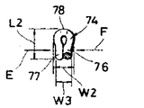
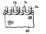
제5a도-제5e도는 슬라이드 파스너 결합 요소의 다른 형태를 예시한다. 제 5a도에 도시된 대로, 결합 엘레멘트 조립체(72)는 구불구불 혹은 지그재그 형을 가진 합성수지제의 연속한 결합 요소들(74)로 구성되고, 결합 요소(74)는 연결부(75)로 상호연결된다. 결합 요소 조립체(72)는 종방향 중심축 주위로 제 5b도에 2점 쇄선으로 표시된 바와 같은 U형 단면으로 절곡된다. 절곡된 결합 요소는 각자 제 5c도 및 제 5d도에 도시된 바와 같은 결합헤드(78)에 의해 상호연결된 1쌍의 다리들(76, 77)을 가진다. 결합 요소(74)의 도시된 치수들, 즉 두께(W1, W2) 및 길이 (L2)는 본 발명의 치수 조정장치에 의해 조정된다. 치수조정된 결합 요소(72)는 재봉사(79)에 의해 슬라이드 파스너 스트링어 테이프의 종연부를 따라 그 스트링어 테이프에 봉착된다.5A-5E illustrate another form of slide fastener coupling element. As shown in FIG. 5A, the
제 6a도 및 제 6b도는 슬라이드 파스너 스트링어 테이프(85)의 종연부위에 있는 보강 코드(83)상에 붙박이로 장착된 불연속한 슬라이드 파스너 결합 요소(83)의 금속 조립체(82)를 나타낸다. 본 발명의 치수 조정장치는 결합 요소(83)의 두께 W4를 제어한다.6A and 6B show a
제 1 및 제 2 압착기 로울(18, 24)들은, 규정된 폭 W1, W2, W3, W4를 얻도록 제 1 및 제 2 압착기 표면들(34, 39)로 결합 요소의 다리들을 압착하는 작용을 한다. 그러므로 제 1 및 제 2 압착기 표면들(34, 39)은, 제 7도에 예시된 바와같은 폭들 W1, W2, W3, W4중 하나와 동일한 거리 W만큼 서로 떨어진 최근접 대향 부분들을 가진다.The first and second compactor rolls 18, 24 act to squeeze the legs of the coupling element onto the first and second compactor surfaces 34, 39 to obtain a defined width W1, W2, W3, W4. do. The first and second compactor surfaces 34, 39 therefore have nearest opposing parts spaced apart from each other by the same distance W as one of the widths W1, W2, W3, W4 as illustrated in FIG. 7.
제 3 및 제 4 압착기 표면들(50, 53)은 결합 요소의 길이 L1, L2중 하나와 같게된 거리 L 만큼 서로 분리 된 최근법 대향 부분들을 가진다.The third and fourth compactor surfaces 50, 53 have recent law opposing parts separated from each other by a distance L equal to one of the lengths L1, L2 of the coupling element.
치수 조정장치(10)의 작동은 다음과 같다. 우선, 제 4c도 및 제 4d도에 도시된 결합 요소들(64)의 치수 조정을 기술한다. 치수 조정장치(10)는 2열의 그런 결합 요소들(64)의 치수 조정을 동시에 처리할 수 있다. 그러나 2열의 결합 요소들이 동일한 방식으로 치수 조정되므로 1열의 결합 요소의 처리만 상술된다. 나사봉들(27, 56)은 슬라이드 블록(21, 54)과 제 1 및 제 3축(20, 52)을 화살 B, H 방향으로 각각 활동(滑動) 시키도록 자신의 축을 중심으로 선회된다. 제 2 및 제 4 압착기 로울(24, 51)은 제 1 압착기 로울(18)에서 떨어진 제 1 및 제 7도의 위치들로 부터 제 1 도의 이점쇄선으로 도시된 위치 혹은 제 8도의 위치들로 이동되고, 여기서 제 1-4 압착기 표면(34, 39, 50, 53)은 서로 더 많이 떨어져 있게된다. 그리고 나서 결합 요소(64)열이 제 1-4압착기 표면들(34, 39, 50, 53) 사이에 삽입된다.The operation of the
그 다음에, 나사봉(27)(56)들은 화살 A, G 방향으로 각각 슬라이드 블록들(21, 54)을 활동시키도록 반대방향으로 회전되어, 제 1-4압착기 표면들(34, 39, 50,. 53)이 제 7 도에 도시된 대로 대향 압착기 표면들로 부터 거리 L, W 만큼 떨어질 때까지 제 2 및 제 4 압착기 로울(24, 51)들을 제 1 압착기 로울(18)쪽으로 이동시킨다.Then, the
결합요소(64)들이 철회기구(61)(제2도)에 의해 화살 Ⅰ 방향으로 이송됨에 따라, 제 1, 2 및 4 압착기 로울들(18, 24, 51)은 결합 요소(64)에 의해 회전된다. 이때, 제 1 및 제 2 압착기 로울들(18, 24)은 스퍼어 기어(35)와 핀 기어(41) 사이의 맛물림에 의해 동기적으로 회전된다.As the
제 1, 2 및 4 압착기 로울들(18, 24, 51)을 통과하는 결합 요소들(64)은 제 1-4압착기 표면(34, 39, 50, 53)들에 의해 규정된 치수들 W1, L1으로 압착된다. 이때, 다리들(68, 69)이 화살 E, F 방향으로 (제 4d도)가해진 힘을 받아 위치적으로 변위되지 않도록 분할 융기부(47, 48)는 결합 요소(64)와 교합하고(제 4 도), 그래서 다리들(68, 69)은 등간격 혹은 피치로 정확하게 분리된다. 게다가, 결합헤드(70)들은 제 3 압착기 표면(50)에 기대어 보유되는 한편, 다리(68, 69)이 단부들은 제 4 표면(53)에 기대어 보유된다. 따라서, 제 3 및 4 압착기 표면(50, 53)에 의해 다리들(68, 69)은 화살 E, F 방향으로 가해진 힘을 받아 정위치에서 종방향으로 변위받지 않게 저지된다. 제 1 및 제 2 압착기 로울들(18, 24)이 동기 회전된 만큼, 제 1 및 제 2 압착기 표면들(34, 39)비동기적인 회전으로 야기될 수 있는 좋지 못한 흠이나 손상을 받지 않게 된다. 스퍼어 기어(35)와 핀 기어(41)사이의 맞물림은, 제 2 압착기 로울(24)이 화살 A, B 방향으로 (제 1 도) 변위된 때라도 동 요 혹은 강제 맞물림에 없이 상기 기들이 균일하게 맞물려 유지되게 하여준다. 따라서, 제 1 및 제 2 압착기 로울들(18, 24)은 부드럽고 균일하게 회전하도록 허용된다. 제1, 제 2 및 제 4 압착기 로울들(18, 24, 51)이 그 간격들을 조절하도록 상대적으로 변위되면서 결합 요소들(64)이 치수조정되고 있는 때, 핀 기어(41)가 스퍼어 기어(35)와 맞물려 유지된 채로 제 1 및 제 2 압착기 로울(18, 24)들은 부드럽고 균일하게 동기 회전한다.Coupling
제10도는 제 5a도-제 5d도에 도시된 바와 같이 결합 요소들(74)을 치수 조정하는 다른 실시예에 따른 치수 조정장치를 나타낸다. 제10도의 치수 조정장치는 제 1 압착기 표면(91)을 가진 제 1 압착기 로울(90)과, 제 1 압착기 표면(91)을 향하는 제 2 압착기 표면(93)을 가진 제 2 압착기 로울(92)을 포함한다. 제 1 및 제 2 압착기 표면들(91, 93)은 서로를 향해 돌출한 도드라진 부분(94, 95)을 가진다. 제 1 및 제 2 압착기 표면(91, 93)은 폭 W2와 같은 거리만큼 서로 분리되고, 도드라진 부분(94, 95)은 폭 W3와 같은 거리만큼 서로 분리된다.FIG. 10 shows a dimensioning device according to another embodiment for dimensioning the
제10도에 도시된 치수 조정장치의 구조적인 명세는 제 1, 3, 7 및 8도에 도시된 치수 조정장치와 동일하다.The structural specification of the dimensional adjusting device shown in FIG. 10 is the same as the dimensional adjusting device shown in FIGS. 1, 3, 7 and 8.
제11도에 도시된 또 다른 실시예에 따르면, 제 6a도 및 제 6b도에 도시된 결합 요소(83)를 치수 조정하도록 치수조정장치가 설계된다. 그 치수조정장치는 슬라이드 파스너 테이프(95)를 수용하도록 반경방향 외측으로 열린 슬로트(98)와 제 4 압착기 표면(97)을 가진 제 3 압착기 로울(96)을 포함한다. 금속 결합 요소(83)를 치수 조정하기 위해 제 1 및 제 2 압착기 로울(88, 89)의 제 1 및 제 2 압착기 표면(86, 87)들은 분할 융기부를 필요로 하지 않는다.According to another embodiment shown in FIG. 11, the dimensioning device is designed to dimension the
제12도는 본 발명의 또 다른 실시예에 따른 치수 조정장치를 나타낸다. 그 치수 조정장치는 스퍼어 기어(101) 및 제 1 압착기 표면(102)을 가진 제 1 압착기 로울(100)과, 제 1 압착기 표면(102)과 마주대한 제 2 압착기 표면(104)을 가진 제 2 압착기 로울(103)을 포함한다. 제 2 압착기 로울(103)은 핀 기어(105)에서 멀리 제 3 압착기 로울(109)의 제 4 압착기 표면(108)을 향하는 제 3 압착기 표면(107)을 가진 반경방향 외측 돌출플랜지(106)와, 핀 기어(105)를 가진다. 작동에 있어서, 결합 요소(11)의 결합헤드(110)는 결합 요소(11)의 다리들에 걸리는 제 3 압착기 로울(109)의 제 4 압착기 표면에 의해 제 3 압착기 표면(107)에 대해 압착된다.12 shows a dimension adjusting apparatus according to another embodiment of the present invention. The dimensioning device comprises a
첨부된 청구범위내에서 본 발명의 원리 및 개념에 벗어나지 않고 여러가지 사소한 변경 및 개조가 당분야에 숙달된 자들에 의해 가해질 수 있다고 생각된다.It is contemplated that various minor changes and modifications may be made by those skilled in the art without departing from the principles and concepts of the invention within the appended claims.
Claims (7)
Applications Claiming Priority (2)
| Application Number | Priority Date | Filing Date | Title |
|---|---|---|---|
| JP59099556A JPS60242804A (en) | 1984-05-17 | 1984-05-17 | Dimension limiting apparatus of slide fastener element |
| JP99556 | 1984-05-17 |
Publications (2)
| Publication Number | Publication Date |
|---|---|
| KR850008612A KR850008612A (en) | 1985-12-21 |
| KR860001833B1 true KR860001833B1 (en) | 1986-10-24 |
Family
ID=14250429
Family Applications (1)
| Application Number | Title | Priority Date | Filing Date |
|---|---|---|---|
| KR1019850002887A KR860001833B1 (en) | 1984-05-17 | 1985-04-29 | Apparatus for dimensioning slide fastener coupling elements |
Country Status (13)
| Country | Link |
|---|---|
| US (1) | US4599065A (en) |
| EP (1) | EP0162218B1 (en) |
| JP (1) | JPS60242804A (en) |
| KR (1) | KR860001833B1 (en) |
| AU (1) | AU552520B2 (en) |
| BR (1) | BR8502473A (en) |
| CA (1) | CA1229471A (en) |
| DE (1) | DE3574950D1 (en) |
| ES (1) | ES8607111A1 (en) |
| GB (1) | GB2158873B (en) |
| HK (1) | HK90589A (en) |
| MY (1) | MY101816A (en) |
| SG (1) | SG56689G (en) |
Families Citing this family (10)
| Publication number | Priority date | Publication date | Assignee | Title |
|---|---|---|---|---|
| JPS60142805A (en) * | 1983-12-29 | 1985-07-29 | ワイケイケイ株式会社 | Method and apparatus for producing fastener element for slide fastener |
| JPH04324162A (en) * | 1991-04-24 | 1992-11-13 | Kenwood Corp | Optical disk reproducing device |
| JP3275932B2 (en) * | 1994-08-02 | 2002-04-22 | ワイケイケイ株式会社 | Method and apparatus for forming continuous element row for slide fastener |
| US5688539A (en) * | 1996-05-03 | 1997-11-18 | Chung Shan Institute Of Science & Technology | Zipper teeth forming mechanism for zipper forming machines |
| JP3320636B2 (en) * | 1997-06-12 | 2002-09-03 | ワイケイケイ株式会社 | Drawer insertion unit of slider for zipper with pull in insert molding machine |
| US6783351B2 (en) * | 2002-07-03 | 2004-08-31 | Hung An Chen | Apparatus for manufacturing slide fastener spiral continuous element row |
| US6783350B2 (en) * | 2002-07-03 | 2004-08-31 | Hung An Chen | Apparatus for manufacturing slide fastener coil-shaped continuous element row |
| TWI220645B (en) * | 2002-10-07 | 2004-09-01 | Gi Kao Young Industry Co Ltd | Nylon zipper teeth and forming screw for producing this nylon zipper teeth |
| DE10331484A1 (en) | 2003-07-11 | 2005-03-03 | Construction Research & Technology Gmbh | Polyurethane-polymer hybrid dispersion with improved surface properties, process for their preparation and their use |
| CN106089884B (en) * | 2016-07-29 | 2017-12-22 | 蚌埠富轩商贸有限公司 | A kind of rotary-type photo frame pressurizing unit |
Family Cites Families (2)
| Publication number | Priority date | Publication date | Assignee | Title |
|---|---|---|---|---|
| JPS5651326A (en) * | 1979-10-01 | 1981-05-08 | Yoshida Kogyo Kk <Ykk> | Method and apparatus for manufacturing slide fastener with synthetic resin zipper |
| JPS6044131B2 (en) * | 1980-08-19 | 1985-10-02 | ワイケイケイ株式会社 | Manufacturing method and device for slide fastener element |
-
1984
- 1984-05-17 JP JP59099556A patent/JPS60242804A/en active Granted
-
1985
- 1985-03-01 GB GB08505308A patent/GB2158873B/en not_active Expired
- 1985-03-05 CA CA000475730A patent/CA1229471A/en not_active Expired
- 1985-03-06 AU AU39552/85A patent/AU552520B2/en not_active Ceased
- 1985-03-15 EP EP85103019A patent/EP0162218B1/en not_active Expired
- 1985-03-15 DE DE8585103019T patent/DE3574950D1/en not_active Expired - Lifetime
- 1985-04-29 KR KR1019850002887A patent/KR860001833B1/en not_active IP Right Cessation
- 1985-05-14 US US06/733,885 patent/US4599065A/en not_active Expired - Fee Related
- 1985-05-16 BR BR8502473A patent/BR8502473A/en not_active IP Right Cessation
- 1985-05-17 ES ES543234A patent/ES8607111A1/en not_active Expired
-
1987
- 1987-08-17 MY MYPI87001350A patent/MY101816A/en unknown
-
1989
- 1989-08-25 SG SG566/89A patent/SG56689G/en unknown
- 1989-11-16 HK HK905/89A patent/HK90589A/en unknown
Also Published As
| Publication number | Publication date |
|---|---|
| MY101816A (en) | 1992-01-31 |
| CA1229471A (en) | 1987-11-24 |
| GB8505308D0 (en) | 1985-04-03 |
| ES543234A0 (en) | 1986-06-01 |
| AU3955285A (en) | 1985-11-21 |
| EP0162218A2 (en) | 1985-11-27 |
| GB2158873B (en) | 1988-02-03 |
| EP0162218B1 (en) | 1989-12-27 |
| AU552520B2 (en) | 1986-06-05 |
| ES8607111A1 (en) | 1986-06-01 |
| JPH0128562B2 (en) | 1989-06-05 |
| HK90589A (en) | 1989-11-24 |
| EP0162218A3 (en) | 1988-03-30 |
| JPS60242804A (en) | 1985-12-02 |
| GB2158873A (en) | 1985-11-20 |
| US4599065A (en) | 1986-07-08 |
| SG56689G (en) | 1989-12-29 |
| KR850008612A (en) | 1985-12-21 |
| BR8502473A (en) | 1986-01-28 |
| DE3574950D1 (en) | 1990-02-01 |
Similar Documents
| Publication | Publication Date | Title |
|---|---|---|
| KR860001833B1 (en) | Apparatus for dimensioning slide fastener coupling elements | |
| JPH11181658A (en) | Product-drawing out device | |
| DE1452724A1 (en) | Rolling machine with inclined rollers | |
| JPS62246617A (en) | Pinch roll | |
| JPH0235605B2 (en) | ||
| US4083215A (en) | Method and tool for making a sheet metal pulley | |
| JPH08170292A (en) | Long spacing press apparatus | |
| JPS59183936A (en) | Roll forming device | |
| DE4126308A1 (en) | TAPE WRAPPING DEVICE FOR TIRE BUILDING MACHINES | |
| DE2519278A1 (en) | METHOD OF FORMING GLASS PANELS BY ROLLING | |
| EP0091690A1 (en) | Apparatus for shaping coiled slide fastener coupling elements | |
| DE4322114C2 (en) | Deflection roller | |
| DE1437594B2 (en) | SCANNING DEVICE FOR A MAGNETIC TAPE DEVICE WITH TWO CYLINDRICAL COAXIAL DRUMS | |
| EP0931750A3 (en) | Winding apparatus for continuous threads | |
| US4608845A (en) | Apparatus for fabricating honeycomb core strip | |
| DE2553556C3 (en) | Adjustment device on photographic enlargers or repro devices | |
| DE3933412A1 (en) | Deflector roller for conveyor belts - consists of rotationally symmetrical drum with bearing pins at ends fitting into hub holes | |
| JPS6245007B2 (en) | ||
| US3137337A (en) | Apparatus for and methods of making a sheet metal strip structure | |
| CN216322241U (en) | Crushing roller for plastic product remodeling | |
| JPH11157619A (en) | Belt conveyor device | |
| KR890005250Y1 (en) | Producing apparatus of a metallic helical pipe | |
| SU1199377A1 (en) | Arrangement for feeding strip and band material to the machining zone | |
| JP3117041B2 (en) | Temporary assembly device for heat exchanger core | |
| JPS6013541Y2 (en) | Entrance/exit guide for rolled material in rolling without caliber |
Legal Events
| Date | Code | Title | Description |
|---|---|---|---|
| A201 | Request for examination | ||
| G160 | Decision to publish patent application | ||
| E701 | Decision to grant or registration of patent right | ||
| GRNT | Written decision to grant | ||
| FPAY | Annual fee payment |
Payment date: 19940930 Year of fee payment: 9 |
|
| LAPS | Lapse due to unpaid annual fee |