KR850000468B1 - Apparatus for strip casting having a heated orifice - Google Patents
Apparatus for strip casting having a heated orifice Download PDFInfo
- Publication number
- KR850000468B1 KR850000468B1 KR1019810001551A KR810001551A KR850000468B1 KR 850000468 B1 KR850000468 B1 KR 850000468B1 KR 1019810001551 A KR1019810001551 A KR 1019810001551A KR 810001551 A KR810001551 A KR 810001551A KR 850000468 B1 KR850000468 B1 KR 850000468B1
- Authority
- KR
- South Korea
- Prior art keywords
- passage
- tundish
- cavity
- casting
- molten metal
- Prior art date
Links
Images


Classifications
-
- B—PERFORMING OPERATIONS; TRANSPORTING
- B22—CASTING; POWDER METALLURGY
- B22D—CASTING OF METALS; CASTING OF OTHER SUBSTANCES BY THE SAME PROCESSES OR DEVICES
- B22D11/00—Continuous casting of metals, i.e. casting in indefinite lengths
- B22D11/10—Supplying or treating molten metal
-
- B—PERFORMING OPERATIONS; TRANSPORTING
- B22—CASTING; POWDER METALLURGY
- B22D—CASTING OF METALS; CASTING OF OTHER SUBSTANCES BY THE SAME PROCESSES OR DEVICES
- B22D11/00—Continuous casting of metals, i.e. casting in indefinite lengths
- B22D11/06—Continuous casting of metals, i.e. casting in indefinite lengths into moulds with travelling walls, e.g. with rolls, plates, belts, caterpillars
- B22D11/0637—Accessories therefor
- B22D11/064—Accessories therefor for supplying molten metal
Landscapes
- Engineering & Computer Science (AREA)
- Mechanical Engineering (AREA)
- Continuous Casting (AREA)
- Casting Support Devices, Ladles, And Melt Control Thereby (AREA)
- Manufacture Of Alloys Or Alloy Compounds (AREA)
- Molds, Cores, And Manufacturing Methods Thereof (AREA)
- Cartons (AREA)
Abstract
Description
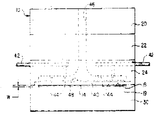
제1도는 구멍통로의 판체 성형부를 가열하기 위한 방법을 설명한 본 발명 턴디쉬의 부분절개 측면도.1 is a partial cutaway side view of the tundish of the present invention illustrating a method for heating a plate-formed part of a hole passage;
제2도는 제1도에 도시된 턴디쉬의 정면도.FIG. 2 is a front view of the tundish shown in FIG.
제3도는 본 발명의 다른 턴디쉬의 부분절개 측면도.3 is a partial cutaway side view of another tundish of the present invention.
제4도는 제3도에 도시된 턴디쉬의 정면도.4 is a front view of the tundish shown in FIG.
제5도는 본 발명의 또 다른 턴디쉬의 정면도.5 is a front view of another tundish of the present invention.
본 발명은 스트립을 신속히 주조하기 위한 새로 개선한 장치에 관한 것으로, 특히 본 발명은 턴디쉬(tundish)의 구멍이 스트립의 주조전 또는 주조중에 가열될 수 있는 턴디쉬에 관한 것이다.The present invention relates to a new and improved apparatus for rapidly casting strips, and more particularly to the tundish, in which the holes of the tundish can be heated before or during casting of the strip.
스트립 주조장치의 개발에 있어서, 용융금속이 주조면으로 공급되는 노즐 또는 오리피스통로(본원에서 이 용어는 "구멍통로"로도 사용됨)는 점차 임의적 형태로 되어 가고 있다. 특히 구멍통로를 구성하는 요홈은 그 종방향 폭이 일정하여야 한다. 주조중 주조면으로부터 구멍리프(ilp)까지의 간격을 일정하게 유지하는 것이 중요하다. 주조조작중 요홈 칫수의 유지와 주조중 구멍통로 응결가능성을 최소한으로 줄이는 것이 스트립의 폭과 구멍의 전체폭이 증가함에 따라 보다 제한적인 고려를 하여야 한다. 따라서, 구멍통로 칫수가 전주조공정 중 일정하게 유지되며 주조중 구멍통로가 응결되는 것을 최소한으로 줄일 수 있는 새로이 개선된 스트립 주조장치가 요구되고 있다.In the development of strip casting apparatuses, nozzles or orifice passages (where the term is also used herein as "hole passages") into which the molten metal is supplied to the casting surface are becoming increasingly arbitrary. In particular, the grooves constituting the hole passages should have a constant longitudinal width. It is important to maintain a constant distance from the casting surface to the hole ripple during casting. The maintenance of groove dimensions during casting operations and the minimum reduction in the possibility of hole passage condensation during casting should be considered more restrictively as the width of the strip and the total width of the holes increase. Therefore, there is a need for a new and improved strip casting apparatus that can maintain a constant hole dimension during the pre-casting process and minimize the condensation of the hole passage during casting.
본 발명은, 용융금속을 수용 및 유지하기 위한 턴디쉬와 구멍통로에서 0.120인치내에 위치하고 200-10,000ft/분당의 표면선속도로 구멍통로를 통과하여 가동하는 주조면으로 용융금속을 턴디쉬로부터 전달하는 두개의 떨어진 리프(lip)로 정의된 구멍통로로 구성된 스트립물질을 연속 주조하기 위한 새로 개량된 장치를 제공하는 것으로 요약할 수 있다.The present invention delivers molten metal from a tundish to a casting surface that is located within 0.120 inches of the tundish and hole passage for accommodating and maintaining the molten metal and moves through the hole passage at a surface linear velocity of 200-10,000 ft / min. It can be summarized as providing a new and improved device for continuous casting of strip material consisting of hole passages defined by two distant lips.
본 발명의 장치에서, 적어도 피나의 란스(lance)가 턴디쉬의 한 부분을 통하여 배치되었고 란스의 선단부는 구멍통로의 적어도 한 리프를 구성하는 한 부분에 인접한 턴디쉬 내공동을 향하여 배설되어 있다. 란스를 통하여 반응성 기체를 턴디쉬내부로 공급하기 위한 장치가 장설되었고 반응성기체로부터의 연소생성물이 턴디쉬의 내부에서 배출될 수 있는 적어도 하나의 배출통로가 장착되었다. 본 발명의 구멍통로를 구성하는 하나의 리프는 용융금속내성판을 포함한다.In the device of the present invention, at least a lance of the pinna is disposed through a portion of the tundish and the tip of the lance is disposed toward a tundish inner cavity adjacent to a portion constituting at least one leaf of the hole passage. An apparatus for supplying the reactive gas into the tundish through the lance was installed and at least one discharge passage was installed in which combustion products from the reactive gas could be discharged inside the tundish. One leaf constituting the hole passage of the present invention includes a molten metal resistant plate.
본 발명의 장점은 가열형 구멍을 갖는 스트립의 주조장치의 제공에 있다.An advantage of the present invention is the provision of an apparatus for casting strips having heated holes.
본 발명의 목적은 턴디쉬의 구멍통로를 구성하는 적어도 한 표면이 주조중 또는 주조전후에 가열되는 개선된 스트립 주조장치를 제공하는 데 있다.It is an object of the present invention to provide an improved strip casting apparatus in which at least one surface constituting a trough of the tundish is heated during or before casting.
본 발명의 다른 목적은 전 주조공정을 통하여 구멍의 칫수가 유지되는 스트립 주조장치를 제공하는데 있다It is another object of the present invention to provide a strip casting apparatus in which the dimension of the hole is maintained through the entire casting process.
본 발명의 목적 및 장점들은 다음의 상세한 기술 및 첨부도면을 참조하면 명확히 이해될 것이다.The objects and advantages of the present invention will be apparent from the following detailed description and the accompanying drawings.
도면을 참조하면 도면은 본 발명의 적당한 장치들을 설명한 것이다.Referring to the drawings, the drawings illustrate suitable devices of the present invention.
제1도-제4도에 도시된 바와 같이 본 발명장치는 부호(10)으로 표시한 턴디쉬를 포함한다. 턴디쉬(10)는 용융금속물을 쏟는 통로로 불리는 내부공동(12)를 갖는다. 이 통로(12)는 제1도와 제3도의 측면도에서 일련의 절선으로 표시되어 있다. 이 내부공동(空洞) 또는 통로는 용융금속을 공급받고 또한 용융금속을 용융상태로 유지하도록 설계되어 있다. 또한 턴디쉬(10)는 노즐 또는 구멍통로(14)를 포함하며 이를 통하여 턴디쉬내의 용융금속이 주조면(16)으로 공급된다.As shown in FIGS. 1-4, the device comprises a tundish, indicated by
본 발명에 있어서, 구멍통로(14)는 상측리프(18)와 하측리프(19)의 두 리프사이로 되었다. 제2도에서 가장 명확하게 도시된 바와 같이 리프(18)과 (19)는 적어도 약 0.010인치의 폭으로 구멍통로의 종연장부에 걸쳐 상호 일정한 간격으로 떨어져 있다.In the present invention, the
한 적당한 실시예에서, 용융금속은 구멍통로(14)로 부터 약 99%의 동을 함유하는 수냉침전경화된 동합금으로 된 휘일의 외주면(16)상에 공급된다. 동 및 동합금은 이들의 높은 열전도성 및 내마모성에 따라 선택되나 다른 재질이 주조면(16)으로 사용될 수도 있다. 본 발명장치의 조작에서, 원형, 평면형 또는 타원형인 주조면(16)은 약 200-10,000ft/분의 표면선속도로 노즐을 통과하여 가동한다.In one suitable embodiment, molten metal is supplied from the
도면에 도시한 바와 같이, 턴디쉬(10)는 적어도 하나의 상측블럭(20)과 적어도 하나의 하측블럭(30)으로 구성된다. 본 발명에서 사용한 상측 또는 하측, 전방 또는 후방이란 용어는 주조면으로부터 떨어져 있는 위치를 나타내는 상측 또는 하측이란 용어와 함께 일반적으로 주조면(16)에 관하여 사용한 것이다. 본 발명 턴디쉬(10)의 상하측블럭(20)(30)은 수직으로 정렬되어 함께 고정시키는 것이 바람직하다. 이러한 수직배열은 본 발명 출원인이 동시 출원한 "스트립 주조장치"에 기술되어 있다. 고정될 블럭들은 통로(12)의 용융금속이 장치의 내면으로 흘러나와서는 안된다. 또한 제2도에 도시된 바와 같이, 구멍통로(14)가 내면에 위치하는 경우 용융 금속은 이를 통과한다. 그러므로 상기에서 언급된 바와 같이 용융물이 통과하여서는 안되는 내면은 턴디쉬(10)의 구멍통로(14)를 포함하는 것을 원하지 않는다.As shown in the figure, the tundish 10 includes at least one
블럭(22)(24)와 같은 몇개의 중간블럭들은 턴디쉬를 수직으로 배열구성하는 경우 상측블럭(20)과 하측블럭(30) 사이에 배치된다. 수평배열형과 같이 여러가지 다른 형태의 턴디쉬가 사용될 수 있으며 용융금속내성재의 조립블럭 또는 단일 구조의 블럭을 사용할 수도 있다.Some intermediate blocks, such as
본 발명 장치에 사용된 블럭은 용융금속의 부식에 대한 내성을 가지는 재질이어야 한다. 따라서 섬유화 카올린으로 제조된 단열판과 같은 단열판이 적합하다. 흑연, 알루미나흑연, 점토성흑연, 내화점토, 석영, 질화보론, 질화규소, 탄화보론, 알루미나, 지르콘, 안정화된 지르콘 규산염, 실리카, 마그네시아, 크롬마그네사이트와 이들의 조합을 포함하는 다른 재질이 상기 블럭의 구성에 이용될 수도 있다.The block used in the device of the present invention should be of a material that is resistant to corrosion of the molten metal. Thus, heat insulating plates such as heat insulating plates made of fibrous kaolin are suitable. Other materials including graphite, alumina graphite, clay graphite, refractory clay, quartz, boron nitride, silicon nitride, boron carbide, alumina, zircon, stabilized zircon silicate, silica, magnesia, chromium magnesite and combinations thereof It may be used for configuration.
적당한 실시예에 턴디쉬는 0.5인치 두께의 "kaolwool"(상표명)파이비보오드로 수직 또는 수평으로 적층하여 만든다. 블럭의 두께는 요구된 스트립 주조조건에 따라 채택된다. 1.5인치 두께의 블럭이 이들을 상업적 이용성 때문에 본 발명에 사용하였다. 더우기 본 발명 실시예에서 이러한 섬유화 카올린 블럭을 사용한 것은 이들이 비교적 저렴하고 원하는 형태로 용이하게 천공하거나 만곡시킬 수 있기 때문이다. 그러나, 상기 열거된 재질말고도 다른 재질이 사용된 수 있고 다른 형태로 만들 수도 있다.In a suitable embodiment, the tundish is made by stacking vertically or horizontally with a 0.5 inch thick " kaolwool " The thickness of the block is adapted according to the required strip casting conditions. Blocks 1.5 inches thick were used in the present invention because of their commercial availability. Furthermore, the use of such fibrillated kaolin blocks in embodiments of the present invention is because they are relatively inexpensive and can be easily drilled or curved to the desired shape. However, other materials than those listed above may be used and may be made in other forms.
본 발명의 턴디쉬(10)는 적어도 하나의 도입통로(32)로 구성된 용융금속주입통로(12)를 포함한다. 도입통로부(32)는 턴디쉬를 통하여 연장되어 턴디쉬(10)의 하부에 움푹 들어간 부분에 형성된 기저통로부(34)가 연결되었다. 도입통로(32)를 위한 개구(開口)가 제1도 및 제3도에 도시된 바와 같이 턴디쉬의 상측면에 배치하였으나 이 개구는 어느 곳에나 설치할 수 있다. 또한 도면에 도시된 바와 같이, 개구는 이를 통하여 용융금속의 공급이 용이하도록 깔대기형의 구조로 모서리가 약간 반원형으로 하는 것이 바람직하다.The tundish 10 of the present invention includes a molten
기저통로(34)의 구멍통로(14)는 본 발명 스트립 주조장치에서 중요한 구조이다. 전형적으로 기저통로(34)는 턴디쉬의 저부에 만곡구성되거나 주조되었다. 기저통로(34)의 저부(38)는 구멍통로(14)의 수직높이 이하에 위치하도록 하는 것이 좋다. 그러나, 이러한 구조는 지정된 것은 아니다. 적당한 실시예에서 기저통로(34)의 저부(38)의 적어도 일부분은 노즐(14)의 하측 적어도 약 0.3인치 아래에 장설되었다. 더우기, 기저통로(34)의 저부(38)은 수평으로부터 적어도 약 30°의 각도로 노즐쪽으로 연장시키는 것이 바람직하다.The
용융금속을 주조면(16)상에 공급하는 구멍통로(14)는 고전 길이를 통하여 폭칫수 W가 일정하다. 이 폭칫수 W는 적어도 약 0.010인치이고 0.120인치 이하이며, 좋기로는 0.080인치 이하가 좋다. 대부분의 실시예에서 이 폭칫수 W는 0.020∼0.060인치, 좋기로는 약 0.030∼0.050인치의 범위내에 있다.The
구멍통로(14)는 본 발명의 장치에서 여러가지 방법으로 구성될 수 있다. 그 한 실시예에서, 구멍통로(14)를 구성하는 적어도 하나의 통로리프는 용융금속의 내성시이트나 판으로 구성되었다. 예를들어, 제2도에 도시된 바와 같이, 구멍통로(14)는 노즐(14)의 상측통로리프(18)를 형성하는 판(40)의 저부와, 노즐(14)의 하측통로리프(19)를 형성하는 턴디쉬(10)의 선단측 리프의 사이에 형성되었다. 구멍통로(14)는 하측판과 턴디쉬사이 또는 두 대향된 판사이에 형성될 수도 있다. 구멍통로(14)를 형성하는데 사용한 방법에 관계없이 상기 언급된 고정적 간격이 유지되어야 한다.The
본 발명에 있어서 적어도 하나의 공동(空洞)이 구멍통로(14)의 적어도 한 통로벽을 형성하는 구조의 적어도 일부분에 인접한 턴디쉬(10)내에 형성되어 있다. 이 공동은 하기에서 서술한 바와 같은 연도(煙道) 또는 배출구(46)의 저면으로 구성된다. 또한 이러한 공동은 제2도 및 제4도에 도시한 바와 같이 다수의 배출구 사이에 연장 형성할 수도 있다. 또 다른 방법으로 이러한 공동은 제5도에 도시된 바와 같이 구멍통로의 한통로 리프를 형성하는 구조의 완전한 연장부를 가로질러 턴디쉬내에 형성될 수도 있다. 좋기로는 판(40) 또는 (70)이 구멍통로의 적어도 한 리프를 이룬다. 이러한 실시예에서, 구멍통로(14)에 대하여 이러한 판의 외측면에 인접한 턴디쉬의 일부가 제기되어 원하는 공동을 제공할 수도 있다. 이래에 기술한 바와 같이, 반응성 기체가 이 공동내로 전달되고 이 기체로부터의 열이 턴디쉬 구조물을 통하여 구멍통로(14)를 가열토록 전달된다. 따라서 이 공동은 이와 같은 결과를 성취할 수 있도록 구멍통로(14)에 충분히 근접 구성되어야 하며, 가열효과는 턴디쉬 재질의 열전도율과 함께 가열온도에 따라 좌우된다.In the present invention, at least one cavity is formed in the
상술한 바와 같이 구멍통로(14)를 형성하는 적어도 한 표면은 분리된 용융금속내성시이트나 판(40)의 저부로 만드는 것이 좋다. 실제로 사용하는 경우 이러한 판(40)은 턴디쉬(10)에 단일체로 구성되거나 다른 방법으로 장설된다. 도시한 바와 같이 구멍통로(14)의 상측통로 리프(18)은 용융금속 내성재질로 된 판(40)의 하측부로 만드는 것이 바람직하다. 주조중 구멍통로(14)의 상측리프(18)를 유지하는 것은 하측리프(19)에 비하여 보다 심각하므로 용융금속에 대하여 충분한 내성을 갖는 판(40)을 사용하는 것이 바람직하다. 그러나 하측리프(19) 또는 구멍통로(14)를 구성하는 상하측 리프(18)(19) 모두를 제3도 및 제4도에 도시한 바와 같이 판(40) 또는 (70)으로 만들 수도 있다. 이 판(40) 또는 (70)은 턴디쉬의 다른 부분만큼 용융금속에 대한 내성을 가져야 하며, 좋기로는 이 판이 턴디쉬(10)의 다른 부분보다 용융금속에 대한 충분한 내성을 가지는 재질로 만드는 것이다. 제2도에 도시한 바와 같이 판체(40)는 턴디쉬(10)의 중간블럭(24)의 저부에 적당히 절취형성한 요홈내에 삽입 고정시킬 수 있다. 또한 이 판(40)은 턴디쉬(10)의 블럭 또는 블럭의 일부로 구성될 수도 있다. 이 판(40)은 구멍통로(14)의 종방향 길이보다 길어야 한다. 따라서 판(40)의 주연단부는 제1도 및 제2도에 도시된 인접블럭(24)(30)사이에 삽입되어 있다.As described above, at least one surface forming the
한 적당한 실시예에서 턴디쉬는 근본적으로 섬유화 카올린으로 만들고 질화보론판(40)으로 구성된 구멍통로(14)를 갖는다. 그러나 턴디쉬와 판의 구성에 질화규소, 탄화규소, 탄화보론, 실리카, 알루미나, 지르콘, 안정화 지르콘 규산염, 흑연, 알루미나흑연, 내화점토, 점토성흑연, 석영, 마그네시아, 크롬마그네사이트와 이들 재질의 배합물이 사용될 수 있다.In one suitable embodiment, the tundish has a
도시한 바와 같이 하나의 란스 또는 두개의 란스가 구멍통로에 인접한 공동내로 연장된 이들의 팁(tip)(44)과 함께 턴디쉬(10)를 통하여 장설되었다. 제1도, 제2도 및 제5도에 도시된 바와 같이, 적당한 란스가 구멍통로(14)의 상측통로 리프(18)를 구성하는 판(40)을 가열토록 내부로 연장되어 있다. 정당한 실시예에서, 적어도 하나의 란스(42)가 그 선단부(44)가 내부를 향하여 연장되어 판(40)의 외측면에 향하도록 턴디쉬내에 장설된다. 또한 제1도 및 제2도에 도시된 바와 같이, 턴디쉬(10)에는 란스(42)로부터 공급된 연소생성물이 턴디쉬내의 내부로부터 배출시킬 수 있는 배출공 또는 연도가 설치될 수 있다.As shown, one or two lances were installed through the
제3도 및 제4도에 도시한 다른 실시예에서 구멍통로(14)의 상측통로 리프(18)와 하측통로(19)사이에 형성된 한쌍의 판(40)(70)의 각각에 인접하여 턴디쉬의 내부를 가열하기 위한 수단이 제공될 수 있다. 구멍의 상측통로 리프를 가열하기 위한 상기 언급된 란스(42)와 더불어 이러한 구조는 그 선단이 하측통로 리프(70)에 인접한 내부를 향하여 구멍통로(14)의 하측통로 리프(19)를 가열토록 턴디쉬(10)내에 배치된 적어도 하나의 란스(72)를 필요로 한다. 또한 동일한 배출공 또는 연도(76)가 란스(72)로부터 판(70)에 인접한 공동에 전달되는 연소생성물이 턴디쉬(10)의 내부로부터 배출되도록 턴디쉬(10) 내에 설치될 수도 있다.In another embodiment, shown in FIGS. 3 and 4, a turn adjacent to each of the pair of
제5도에 도시된 바와 같이 다수의 선단부를 가지는 란스 또는 수개의 란스를 턴디쉬(10)로부터 주조되는 스트립의 폭에 따라 사용할 수 있다. 이러한 가열 란스를 이용함으로서 턴디쉬 구조물을 통하여 주조전 또는 주조중에 노즐을 가열토록 구멍통로(14)의 해당통로 리프로 열을 전달할 수 있도록 충분한 열이 공동으로 공급되어 유지된다. 판(40) 또는 (70)이 사용될 때에 전체 판(40)의 온도는 스트립의 주조 초기보다 높게 상승할 수도 있다. 한 적당한 실시예에서 하나의 란스가 구멍통로의 폭상에 2.0∼3.0인치마다 장설된다. 이러한 판을 용융온도 근처, 예를 들어 주조될 합금의 용융온도의 약 10% 범위내의 온도로 가열함으로서 특히 주조초기에 일어나기 쉬운 구멍통로(14)의 금속용결을 방지할 수 있다. 또한 이러한 판을 금속주조온도로 또는 이 온도 가까이로 예열함으로서 사전의 팽창 및 수축효과가 이루어지도록 하여 적당한 보상이 이루어지게 한다. 따라서, 예열은 현재의 구멍칫수와 주조며으로부터의 간격이 주조 공정을 통하여 설정된 대로 남도록 한다.As shown in FIG. 5, a lance having a plurality of tips or several lances may be used depending on the width of the strip cast from the
적당한 한 실시예에서, 고온의 반응성 기체가 란스를 통하여 공급된다. 이러한 기체는 란스의 선단부를 통과하고 화염이 내부를 향하여 뻗흰 다음 구멍통로(14)의 통로 리프를 구성하는 부분을 향하게 된다. 반응성 기체로는 아세칠렌-공기아세칠-산소, 천연가스-산소혼합체를 포함한다. 판(40), 또는 판(40)(70)과 같은 부분이 화염에 의하여 영향을 받을 가능성을 줄이기 위하여, 화염이 부딪치는 부분인 상측 판(40)의 적어도 상측면 일부와 하측판(70)의 하측면에 내열정도층(48)(78)을 도층할 수 있다. 이러한 층(48)은 제한된 화학적인 공격을 포함하는 화염의 나쁜 효과를 흡수하도록 작용하고 또한 판(40)(70)을 통하여 열을 전도하도록 작용한다. 한 실시예에서, 이러한 층(48)은 약 3/16∼1/4인치 두께의 흑연으로 되어 있으나 다른 재질의 사용도 가능하다. 열 및 화학적인 약효과를 흡수하고 열을 전도할 수 있는 흑연질 시멘트 또는 다른 내화코팅물질을 사용함으로서 질화보론판상에 보호층 또는 다수의 층을 도층할 수도 있다.In one suitable embodiment, hot reactive gas is supplied through the lance. This gas passes through the tip of the lance and the flame extends inwards and then towards the part that makes up the passage leaf of the
제1도-제3도에 도시된 바와 같이, 턴디쉬의 하측부에는 배출마개(62)가 착설되어 있다. 이 배출 마개는 중력에 대하여 구멍통로 또는 노즐(14) 아래에 수직으로 장설하는 것이 바람직하다. 배출마개(62)의 목적은 주조공정을 중지할 필요가 있을 때에 구멍통로(14)로부터 용융금속이 공급되는 것을 신속히 정지시킬 수 있도록 하는 데 있다. 본 발명의 기술분야에 숙련된 자이면 신속히 주조공정을 중지시키는 것이 매우 중요한 것임을 이해할 수 있을 것이다. 그밖에 부정적이고 간헐적인 용융금속의 공급이 주조공정의 종료시에 노즐(14)을 통하여 일어나는 경우가 있는 바, 이러한 간헐적 흐름이 스트립 주조에 제어없이 신속히 가동하는 주조면에 부딪치게 된다. 따라서 주조공정 종료시 노즐을 통한 용융금속의 이러한 제어되지 않은 낙류가 주조제품상에 튀기어 손상을 입히고 어떤 경우 스트립 주조장치에 피해를 주게 된다. 또한 턴디쉬의 재사용을 위하여 주조공정의 종료시 턴디쉬(10)로부터 공동(12)내의 용융금속을 배출시키는 것이 중요하다. 마개(62)를 제거함으로서 턴디쉬내의 모든 용융금속은 마개공을 통하여 배출되어 턴디쉬(10)와, 구멍통로(14)를 구성하는 판(40)(70)이 다음 주조공정에 재사용이 가능하게 된다. 마개(62)를 뽑은 후 턴디쉬로부터 마개공을 통하여 흘러나오는 용융금속을 받기 위한 적당한 용기가 제공되어야 할 것임을 이해할 수 있을 것이다.As shown in Figs. 1 to 3, a
비록 본 발명의 실시형태들이 설명의 목적한 바로 상기와 같이 기술되었으나 본 발명의 기술분야에 숙련된 자이면 본 발명의 기술사상을 벗어남이 없이 여러가지 수정이 가능한 것이다.Although the embodiments of the present invention have been described as just for the purpose of description, those skilled in the art can make various modifications without departing from the technical spirit of the present invention.
Claims (1)
Applications Claiming Priority (2)
| Application Number | Priority Date | Filing Date | Title |
|---|---|---|---|
| US19409780A | 1980-10-06 | 1980-10-06 | |
| US194.097 | 1980-10-06 |
Publications (2)
| Publication Number | Publication Date |
|---|---|
| KR830005938A KR830005938A (en) | 1983-09-14 |
| KR850000468B1 true KR850000468B1 (en) | 1985-04-08 |
Family
ID=22716287
Family Applications (1)
| Application Number | Title | Priority Date | Filing Date |
|---|---|---|---|
| KR1019810001551A KR850000468B1 (en) | 1980-10-06 | 1981-05-04 | Apparatus for strip casting having a heated orifice |
Country Status (14)
| Country | Link |
|---|---|
| EP (1) | EP0049556A1 (en) |
| JP (1) | JPS5764455A (en) |
| KR (1) | KR850000468B1 (en) |
| AT (1) | AT384764B (en) |
| AU (1) | AU6997581A (en) |
| BR (1) | BR8102816A (en) |
| CA (1) | CA1183321A (en) |
| ES (1) | ES8304823A1 (en) |
| HU (1) | HU183422B (en) |
| MX (1) | MX155524A (en) |
| NO (1) | NO811580L (en) |
| PL (1) | PL231044A1 (en) |
| RO (1) | RO83019B (en) |
| YU (1) | YU97181A (en) |
Families Citing this family (1)
| Publication number | Priority date | Publication date | Assignee | Title |
|---|---|---|---|---|
| DE4234255C2 (en) * | 1992-10-10 | 1994-09-15 | Sundwiger Eisen Maschinen | Belt casting device comprising a casting vessel and a pair of cooled casting wheels forming a casting gap |
Family Cites Families (3)
| Publication number | Priority date | Publication date | Assignee | Title |
|---|---|---|---|---|
| GB521689A (en) * | 1938-08-22 | 1940-05-29 | Joseph Marcel Merle | Improvements relating to apparatus for making products derived from molten metal |
| US4142571A (en) * | 1976-10-22 | 1979-03-06 | Allied Chemical Corporation | Continuous casting method for metallic strips |
| YU43229B (en) * | 1980-05-09 | 1989-06-30 | Battelle Development Corp | Device for continuous band casting |
-
1981
- 1981-04-14 YU YU00971/81A patent/YU97181A/en unknown
- 1981-04-29 AU AU69975/81A patent/AU6997581A/en not_active Abandoned
- 1981-05-04 KR KR1019810001551A patent/KR850000468B1/en active
- 1981-05-05 HU HU811176A patent/HU183422B/en unknown
- 1981-05-07 BR BR8102816A patent/BR8102816A/en unknown
- 1981-05-07 RO RO104230A patent/RO83019B/en unknown
- 1981-05-08 NO NO811580A patent/NO811580L/en unknown
- 1981-05-08 MX MX187192A patent/MX155524A/en unknown
- 1981-05-08 PL PL23104481A patent/PL231044A1/xx unknown
- 1981-05-08 ES ES502054A patent/ES8304823A1/en not_active Expired
- 1981-05-08 CA CA000377258A patent/CA1183321A/en not_active Expired
- 1981-05-08 AT AT0206081A patent/AT384764B/en not_active IP Right Cessation
- 1981-05-08 JP JP56068443A patent/JPS5764455A/en active Granted
- 1981-05-08 EP EP81302065A patent/EP0049556A1/en not_active Withdrawn
Also Published As
| Publication number | Publication date |
|---|---|
| ATA206081A (en) | 1987-06-15 |
| RO83019B (en) | 1984-01-30 |
| AU6997581A (en) | 1982-04-22 |
| ES502054A0 (en) | 1983-03-16 |
| PL231044A1 (en) | 1982-04-13 |
| YU97181A (en) | 1984-08-31 |
| BR8102816A (en) | 1982-08-24 |
| MX155524A (en) | 1988-03-24 |
| CA1183321A (en) | 1985-03-05 |
| AT384764B (en) | 1988-01-11 |
| EP0049556A1 (en) | 1982-04-14 |
| HU183422B (en) | 1984-05-28 |
| ES8304823A1 (en) | 1983-03-16 |
| JPH0341259B2 (en) | 1991-06-21 |
| RO83019A (en) | 1984-01-14 |
| KR830005938A (en) | 1983-09-14 |
| NO811580L (en) | 1982-04-07 |
| JPS5764455A (en) | 1982-04-19 |
Similar Documents
| Publication | Publication Date | Title |
|---|---|---|
| WO2008086580A1 (en) | Delivery nozzle with more uniform flow and method of continuous casting by use thereof | |
| KR850000468B1 (en) | Apparatus for strip casting having a heated orifice | |
| EP0049937B1 (en) | Apparatus and method for strip casting | |
| JPH1085907A (en) | Method for casting metallic strip and equipment therefor and refractory nozzle | |
| JP3567225B2 (en) | Machine and method for casting metal strip | |
| US4488590A (en) | Apparatus for strip casting having a heated orifice | |
| CA1178018A (en) | Apparatus for strip casting having a heated orifice | |
| KR850000518Y1 (en) | Apparatus for strip casting having a heated orifice | |
| KR850000921B1 (en) | Apparatus for strip casting | |
| CA1195086A (en) | Method and apparatus for strip casting | |
| JPS6160247A (en) | Preheater for immersion nozzle for continuous casting | |
| KR850001745Y1 (en) | Tundish in a stell strip casting apparatus | |
| JP2020179412A (en) | Induction heater for immersion nozzle and method of pre-heating immersion nozzle | |
| JPS5781944A (en) | Continuous casting device | |
| JPH10211553A (en) | Metal strip casting method, device therefor and refractory nozzle for supplying molten metal to casting pool of twin roll strip casting device | |
| JPH05269552A (en) | Cover for protecting molten metal surface in continuous casting equipment having movable mold wall | |
| JPH01293943A (en) | Twin roll type continuous casting machine | |
| JPS6012262A (en) | Continuous casting device for thin plate | |
| JPS5639157A (en) | Continuous casting method | |
| JPH06126395A (en) | Pouring nozzle for continuous casting of wide and thin cast strip | |
| JPH04138854A (en) | Preheating device for flat casting nozzle | |
| CS264603B1 (en) | Method of molten metal treatment and vessel for its realization |