KR840001392B1 - Fastener chain finishin apparatus - Google Patents
Fastener chain finishin apparatus Download PDFInfo
- Publication number
- KR840001392B1 KR840001392B1 KR8202192A KR820002192A KR840001392B1 KR 840001392 B1 KR840001392 B1 KR 840001392B1 KR 8202192 A KR8202192 A KR 8202192A KR 820002192 A KR820002192 A KR 820002192A KR 840001392 B1 KR840001392 B1 KR 840001392B1
- Authority
- KR
- South Korea
- Prior art keywords
- punch
- fastener chain
- stopper
- forming
- bender
- Prior art date
Links
Images


Classifications
-
- B—PERFORMING OPERATIONS; TRANSPORTING
- B21—MECHANICAL METAL-WORKING WITHOUT ESSENTIALLY REMOVING MATERIAL; PUNCHING METAL
- B21F—WORKING OR PROCESSING OF METAL WIRE
- B21F45/00—Wire-working in the manufacture of other particular articles
- B21F45/16—Wire-working in the manufacture of other particular articles of devices for fastening or securing purposes
- B21F45/18—Wire-working in the manufacture of other particular articles of devices for fastening or securing purposes of slide fastener elements
-
- A—HUMAN NECESSITIES
- A44—HABERDASHERY; JEWELLERY
- A44B—BUTTONS, PINS, BUCKLES, SLIDE FASTENERS, OR THE LIKE
- A44B19/00—Slide fasteners
- A44B19/42—Making by processes not fully provided for in one other class, e.g. B21D53/50, B21F45/18, B22D17/16, B29D5/00
- A44B19/60—Applying end stops upon stringer tapes
-
- A—HUMAN NECESSITIES
- A44—HABERDASHERY; JEWELLERY
- A44B—BUTTONS, PINS, BUCKLES, SLIDE FASTENERS, OR THE LIKE
- A44B19/00—Slide fasteners
- A44B19/42—Making by processes not fully provided for in one other class, e.g. B21D53/50, B21F45/18, B22D17/16, B29D5/00
- A44B19/58—Removing interlocking members to produce gaps
-
- B—PERFORMING OPERATIONS; TRANSPORTING
- B21—MECHANICAL METAL-WORKING WITHOUT ESSENTIALLY REMOVING MATERIAL; PUNCHING METAL
- B21D—WORKING OR PROCESSING OF SHEET METAL OR METAL TUBES, RODS OR PROFILES WITHOUT ESSENTIALLY REMOVING MATERIAL; PUNCHING METAL
- B21D53/00—Making other particular articles
- B21D53/46—Making other particular articles haberdashery, e.g. buckles, combs; pronged fasteners, e.g. staples
- B21D53/50—Making other particular articles haberdashery, e.g. buckles, combs; pronged fasteners, e.g. staples metal slide-fastener parts
- B21D53/56—Making other particular articles haberdashery, e.g. buckles, combs; pronged fasteners, e.g. staples metal slide-fastener parts stops
Abstract
Description
제1도는 본 발명장치의 일실시예에서 요부의 일부단면을 나타낸 측면도.Figure 1 is a side view showing a partial cross-section of the main portion in one embodiment of the present invention.
제2도는 제1도중 선II-II에 따라 취한 단면도.2 is a cross-sectional view taken along line II-II of FIG. 1.
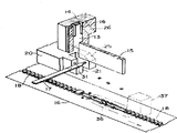
제3도는 동일한 실시예의 장치중 요부의 일부 단면을 나타낸 사시도.3 is a perspective view showing a partial cross section of the main part of the apparatus of the same embodiment;
제4도-제7도는 동일한 실시예의 기계작용을 설명하기 위한 부분도.4 to 7 are partial views for explaining the mechanism of the same embodiment.
제8도는 본 발명장치에 의한 가공후의 파스너 체인을 나타낸 부분도이다.8 is a partial view showing a fastener chain after processing by the apparatus of the present invention.
* 도면의 주요부분에 대한 부호의 설명* Explanation of symbols for main parts of the drawings
13 : 성형펀치 14 : 절단펀치13: forming punch 14: cutting punch
15 : 보조펀치 16 : 파스너체인15: auxiliary punch 16: fastener chain
17 : 선재 18 : 엘레멘트17: wire rod 18: element
20 : 벤더(bender) 21 : 성형대(臺)20: bender 21: molding table
31 : 공기분출구 35 : 보조대31: air outlet 35: support
s : 정지구 d : 스페이스s: stopper d: space
본 발명은 파스너 체인의 마무리 가공장치에 관한 것으로서, 보다 상세하게 설명하면 반가공품으로 길이가 긴 형상의 파스너 체인으로부터 최종 제품의 길이로 파스너 체인을 만들어냄에 있어서 연속 엘레멘트열을 가진 길이가 긴 형상의 파스너 체인에 소정의 간격마다 정지구를 고정함과 아울러 이 정지구의 고정위치에 소정갯수의 엘레멘트군(群)을 제거함에 따라 이 길이가 긴 형상의 파스너 체인에 스페이스를 형성하는 마무리 가공장치에 관한 것이다.The present invention relates to a finishing apparatus for a fastener chain. More specifically, the present invention relates to a semi-finished product having a long shape having a continuous row of elements in forming a fastener chain from the long-length fastener chain to the length of the final product. A finishing apparatus for fixing a stopper to a fastener chain at predetermined intervals and forming a space in the long fastener chain by removing a predetermined number of elements at a fixed position of the stopper. will be.
종래 반가공품으로서 길이가 긴 형상의 파스너 체인으로부터 최종제품의 길이로 파스너 체인을 만듦에 있어서는 이 길이가 긴 형상의 파스너 체인을 최종제품의 길이로 절단하기 전에 연속된 엘레멘트열을 가진 길이가 긴 형상의 파스너 체인에 소정의 간격마다 정지구를 고정함과 아울러 이 정지구의 고정위치에 소정갯수의 엘레멘트군을 테이프로부터 제거함에 따라 최종제품의 길이로 절단하여 스페이스를 형성한다. 상기한 정지구의 고정은 미리 성형된 정지구 부분을 부품공급 장치로부터 한개 한개 공급하여 상하로 움직이는 펀치(Punch)에 의해 파스너 체인에 박아 넣음에 따라 행하여지며, 또한 상기한 스페이스의 형성은 제거해야 할 엘레멘트군의 두부를 펀치와 대(臺)에 의해 상하로부터 타발(打拔)함에 따라 행하여지는 것이 일반적이다.As a conventional semi-finished product, in making a fastener chain from a long-length fastener chain to the length of the final product, the long-shaped shape having a continuous row of elements before cutting the long-length fastener chain to the length of the final product. The stopper is fixed to the fastener chain at predetermined intervals, and a predetermined number of elements are removed from the tape at the fixed position of the stopper, thereby cutting to a length of the final product to form a space. The fixing of the stopper is carried out by feeding the preformed stopper part one by one from the parts supply device and driving it into the fastener chain by a punch moving up and down. It is common to carry out the head of an element group by punching from the top and the bottom with a punch and a stand.
그리고 이 정지구의 고정과 스페이스의 헝성은 가공의 고속화를 기도해야 할 인접한 위치에서 동시 또는 연속하여 행하는 것이 보통이다. 특히 바지등에 사용되는 파스너 체인과 같이 파스너 테이프에 단추덮개가 부착되어 있는 것은 스페이스부 작성 및 정지기 부착가공때에 단추덮개가 방해가 되므로 각 가공에 있어서 단추덮개의 절곡을 행하지 않으면 안되지만 스페이스부 작성과 정지구의 부착을 동시 또는 연속하여 행하면 단추덮개의 절곡조작이 한번으로 끝나기 때문에 조작이 현저하게 단순화된다.The fixing of the stopper and the opening of the space are usually performed simultaneously or successively at adjacent positions where the speed of processing is to be increased. In particular, if the button cover is attached to the fastener tape, such as a fastener chain used for pants, etc., the button cover is obstructed during the creation of the space part and the stopper attachment process. Therefore, the button cover must be bent in each process. When the and the stopper are attached simultaneously or sequentially, the bending operation of the button cover is completed in one step, and the operation is significantly simplified.
그렇지만 상기한 바와같이 미리 성형된 정지구 부분을 부분 공급장치로부터 한개씩 공급하여 펀치에 의해 파스너체인에 박아넣은 방법은 부품단가가 높아지게 되므로 바람직스럼지 못하다. 그래서 정지구 부착위치에 정지구 형성용의 선재를 공급하여 성형대 및 절단펀치에 의해 소정의 길이 및 형상으로 절단한 후, 이 절단편을 성형펀치에 의해 정지구 형상으로 성형하면서 파스너 체인에 박아 넣는 방법을 채용하는 것이 바람직하다. 그렇지만 이와같이 스페이스 작성장치에 근접하여 성형대나 절단펀치 및 성형펀치등을 설치하면 스페이스 작성시에 타발된 엘레멘트의 잔편(殘片)이 파스너 체인의 송출시에 스페이스 작성장치의 엘레멘트 가이드에 닿아 튀어오르는 결과, 인접하는 성형대 및 절단펀치등에 의해 형성되는 간극내로 파고 들어가 정지구 부착장치의 기능을 정지시키거나 불량정지구를 만들게 되는 결점이 발생한다.However, as described above, the method of supplying the preformed stopper portions one by one from the partial feeder and injecting them into the fastener chain by the punch is not preferable because the cost of parts increases. Therefore, the wire rod for forming the stopper is supplied to the stopper attachment position and cut into a predetermined length and shape by the forming table and the cutting punch, and then the cut piece is driven into the fastener chain while being molded into the stopper shape by the molding punch. It is preferable to employ a method of loading. However, if the forming table, cutting punch, forming punch, etc. are installed in close proximity to the space creating device, the resulting fragments of the elements that are punched out when the space is created will come into contact with the element guide of the space creating device when the fastener chain is sent out. A defect arises in digging into the gap formed by the adjacent forming table, the cutting punch, etc. to stop the function of the stopper attaching device or to make a bad stop.
본 발명은 상기한 종래의 결점을 제거한 것으로서, 본 발명은 엘레멘트가 연속하여 식설된 길이가 긴 형상의 파스너체인에 소정의 간격마다 정지구를 고정하는 정지구 부착장치와, 이 정지구 부착장치에 인접하여 배설되며 또한 파스너 체인에서 소정길이에 걸쳐 엘레멘트군을 제거하는 스페이스의 작성장치를 갖추고, 앞에 기술한 정지구 부착장치가 성형대를 갖춘 벤더와 이 성형대상에 공급되는 정지구 형성용 선재를 소정의 길이 및 형상으로 절단하는 절단펀치와 이 절단된 선재편을 정지구 형상으로 성형하면서 파스너 체인상에 고정되는 성형펀치를 포함하며, 상기한 스페이스부 작성장치가 맞물린 엘레멘트군의 두부를 상하로부터 타발해야 할 보조펀치와 보조대를 포함하는 파스너 체인의 마무리 가공장치에 있어서 상기한 벤더에 성형대를 향해 공기를 분출하는 공기분출구를 설치하여 부품단가의 절감화를 도모하면서 엘레멘트 잔편을 정지구 부착장치에서 멀어지도록 날려 버려 정지구 부착장치의 기능 보전과 불량 정지구 생성의 방지를 도모한 것을 특징으로 하는 것이다.The present invention removes the above-mentioned conventional drawbacks, and the present invention provides a stopper attachment device for fixing a stopper at predetermined intervals to a long-length fastener chain in which elements are continuously implanted, and to the stopper attachment device. A device for creating a space which is disposed adjacent to and removes a group of elements over a predetermined length from the fastener chain, and the stopper attaching device described above is provided with a bender having a forming table and a stopper forming wire supplied to the molding target. A cutting punch for cutting into a predetermined length and shape and a forming punch fixed to the fastener chain while forming the cut wire piece into a stop shape, wherein the head portion of the element group engaged with the above-described space portion producing apparatus is engaged from above and below; In the finishing processing apparatus of the fastener chain including the auxiliary punch and the support to be punched, By installing an air blower that blows out the air to reduce the cost of parts, the remaining element is blown away from the stopper attachment device to prevent the malfunction of the stopper attachment device and prevent the generation of defective stoppers. It is.
이하 첨부된 도면에 따라 본 발명에 알맞는 실시예에 관해 설명하면 다음과 같다.Hereinafter, preferred embodiments of the present invention will be described with reference to the accompanying drawings.
제1도-제2도에 나타낸 바와같이 본 발명에 의한 마무리 가공장치(10)은 베이스(base l1)과, 이 베이스(11)상에 입설된 중공(中空)형상의 후레임(12)를 포함한다.As shown in Fig. 1 to Fig. 2, the
이 후레임(12)내에는 정지구 부착장치의 일부를 구성하는 성형펀치(13)및 절단펀치(14)와 스페이스 작성장치의 일부를 구성하는 보조펀치(15)가 배치되어 있는데 상하로 섭동안내 되도록 되어있다. 절단펀치(14)는 제3도에 나타내는 바와같이 파스너 체인(16)의 송출 방향족(이하, 이 방향을 하류측, 반대방향을 상류측 이라고 한다)에 성형펀치(13)을 섭동 자재롭게 수용하는 세로흠(16)을 가지며 또한 해당 정지구 부착장치로 공급되는 정지구 형성용 선재(17)을 소정의 형상으로 절단하기 위해 상응하는 단면형상을 갖는다. 한편 성형펀치(13)은 절단펀치(14)의 세로홈(16)내를 보조펀치(15)와 함께 상하로 움직이기 위해 이 보조펀치와 일체로 형성되어 있다. 보조펀치(15)는 성형펀치(13)의 하류측에 인접하여 배치되며, 서로 맞물리는 연속된 엘레멘트 열(18)을 갖는 파스너 체인(16)으로부터 소정갯수의 엘레멘트 두부를 타발하기 위해 적당한 길이와 두께를 갖는다. 이들 절단펀치(14)와 성형펀치(13) 및 보조펀치(15)는 도시하지 않은 단일의 펀치홀더에 지지되어 주기적으로 상하운동 되도록 되어 있으나 절단펀치(14)와 성형펀치(13) 및 보조펀치(15)는 도시하지 않은 캠 및 링크기구에 의해 일체적으로 하강한 후 절단펀치(14)의 하강정지에 구애됨이 없이 성형펀치(13)과 보조펀치(15)가 다시 하강할 수 있도록 되어있다.In the
후레임(12)의 파스너 체인 공급상류측에 횡방향으로 연신되는 개구(開口)(19)가 설치되어, 이 개구(19)내로 벤더(20)이 섭동자재롭게 수용되어 있다. 벤더(20)은 하류측 선단에 상기한 성형펀치(13)과 같이, 작용하는 성형대(21)들 가지며, 이 성형대는 정지구 부착장치의 일부를 구성한다. 상기한 벤더(20)의 상류측단에는 후레임(12)의 외면에 계합하는 정지장치(22)가 형성되어 있는데, 이에 따라 벤더의 돌출위치 결국 성형대(21)의 돌출위치를 규제하도록 되어있다. 벤더(20)과 후레임(12)의 연장부(23) 사이에는 스프링(24)가 압축되어 있어 벤더(20)을 항상 돌출위치로 부세하고 있다. 또한 벤더의 하류 측단에는 캠면(25)가 형성되어 있는데, 이 캠면(25)는 절단펀치(14)에 형성된 캠면(26)과 계합할 수 있도록 되어 있으며 이에 따라 벤더(20)은 절단펀치(14)가 하강하였을 때에 스프링(24)의 힘에 대항하여 후퇴위치로 이동되도록 되어 있다.An opening 19 extending laterally in the fastener chain supply upstream side of the
벤더(20)은 도시한 바와같이 중공형상으로 되어 있으며 이 중공부내에 도시하지 않은 공기압의 원천에서 튜브(27) 및 볼트(28)에 의해 연장부(23)에 고정된 파이프(29)를 사이에 두고 고압공기가 공급되도록 되어 있다. 파이프(29)의 선단은 시일(seal, 30)을 사이에 두고 벤더(20)의 기밀(氣密)을 유지해도 해당 파이프에 대한 벤더의 섭동이 허용되도록 되어있다. 이 벤더(20)에 공급된 공기는 분출구(31)을 사이에 두고 성형대상(21)으로 분출되도록 되어 있다. 또한 중공부내에서 파이프(29) 선단과 벤더(20)의 사이에 스프링(32)가 끼워져 있으며, 스프링(24)와 함께 벤더(20)을 항상 돌출위치로 압압(押壓)하고 있다.The
베이스(11)상에는 평평한 안내면(33)이 형성되며, 이 안내면은 후레임(12)의 연장부 하면과 함께 해당 마무리가공장치에 공급되는 파스너 체인(16)의 체인가이드를 형성하고 있다. 또한 이 베이스(11)상에는 상기한 성형펀치(13)과 상하방향으로 정열하여 정지구 부착장치의 일부를 구성하는 받침대(34)는 형성되어 있는데 이 받침대(34)는 성형펀치(13)과 같이 작용하여 파스너 체인(16)에 정지구를 형성하면서 고정된다. 더우기 베이스(11)상에는 상기한 보조펀치(15)와 상하방향으로 정열하여 스페이스부 작성장치의 일부를 구성하는 보조대(35)가 형성되어 있는데, 이 보조대(35)는 보조펀치(15)를 받아들이는 홈을 가지며, 이 보조펀치(15)와 함께 제거해야할 소정갯수의 엘레멘트(18)두부를 타발하도록 되어 있다. 이 보조대(35)는 또한 엘레멘트 가이드(36)과 함께 해당 마무리 가공장치를 통과하는 파스너 체인(16)의 체인 가이드를 형성하고 있다.A
상기한 엘레멘트 가이드(36)은 보조펀치(15)를 받아 들이도록 제3도에 나타내는 것처럼 두갈래로 되어 있으며 그 일단부를 후레임(12)에 고정된 브래킷트(brachet′37)에 핀 (38)로서 추착(樞着)되어 있는데 이 엘레멘트가이드(36)의 하류측 단부에는 앵글(Aagle) 부재(39)가 고정되어 후레임(12)에 계지된 스프링(40)에 의해 상방으로 인장되어 있다. 이에 따라 엘레멘트 가이드(36)은 보조대(35)와의 사이에 파스너체인(16)의 이동을 해치는 일없이 이 파스너 체인을 적당한 가압력으로서 협압(俠壓)하도록 되어 있다.The
제2도에 가장 잘 나타낼 바와같이 본 발명의 마무리 가공장치는 정지구 형성용 선재(17)을 성형대(21)상에 간헐적으로 공급하는 선재공급장치(41)을 갖추고 있다. 이 장치는 후레임(12)의 일측에 돌출된 브래킷트(42)상에 지지된 지지물(43)에 따라 다수 이간(離間) 배치된 선재가이드(44)(도면에서는 1개만 니타냄). 후레임(12)의 일측에 고정된 정지레버(45)와 상술한 펀치흘더의 상하운동과 같은 시기에 소정의 각도만큼 선재공급 방향으로 요동하는 요동레버(46)을 포함한다. 선재가이드(44)는 도시하지 않은 선재 공급원에서 양레버(45), (46)에 지지된롤(roll)(47), (48) 사이로 선재(17)을 순조롭게 안내한다. 정지레버(45)는 일측에서 타측으로 향해 정차 벌어지는 안내홈(49)를 가지며 이 롤(47)의 양단은 해당 정지레버(45)의 양측(도면에서는 일측만을 나타냄)에서 상단부를 핀(50)으로서 이 레버에 추착되며 또한 중간부를 이 레버(45)에 스프링(51)로서 연결된 롤홀더(52)의 긴구멍(53)내에 유삽(遊揷)되어 있다. 이에 따라 정지레버(45)에 유지된 상하 한쌍의 롤(47)은 선재공급 방향으로의 이동을 허용하지만 반대방향의 이동을 저지하도록 되어있다. 한편 요동레버(46)은 도시하지 않은 캠기구에 의해 펀치홀더가 상하운동할 때마다 도시하지 않은 상방의 추착점을 중심으로 하부가 좌우로 요동되는 것으로서, 정지레버(45)에 스프링(53)인 연결되어 또한 정지레버(45)와 마찬가지로 일측에서 타측을 향해점차 벌어지는 롤안내홈(54)를 가지며, 이 롤(48)의 양단은 해당 레버(46)의 양측(도면에서는 일측만을 나타냄)에서 상단부를 핀(55)로서 이 레버(46)에 추착되고 또한 중간부를 레버(46)에 스프링(56)으로서 연결된 롤홀더(57)의 긴구멍(58)내에 유삽되어 있다. 이에 따라 요동레버(46)에 지지된 상하 한쌍의 롤(48)은 해당 레버(46)이 선재공급 방향과 반대 방향으로 요동할 때에 선재(17)상을 자유롭게 구르며, 스프링(53)의 작용에 따라 선재공급 방향으로 복귀할 때에 선재(17)을 협압지지하여 공급방향으로 보번다. 이와같이 하여 양레버(45), (46)에 의해 선재(17)은 일정한 거리씩 간헐적으로 공급할 수가 있다.As best shown in FIG. 2, the finishing apparatus of the present invention is equipped with a wire
다음에 본 발명장치의 작용에 관해 기술하면 연속된 엘레멘트열(18)을 가진 파스너 체인(16)이 도시되지 않은 공급롤에서 제1도에 도시한 바와같이 안내면(33) 및 체인가이드(35), (36)에 삽입되어 간헐적으로 소정의 거리씩 화살표 방향으로 이동된다. 이 파스너 체인의 간헐적인 이동은 해당 기계의 하류측에 있는 간헐구동장치에 의해 행하여진다. 이때 성형펀치(13) 및 절단펀치(14)는 제4도에 도시한 바와같이 상승위치에 있으며 또한 벤더(20)상에는 정지구 형성용 선재(17)이 공급되고 있다. 상기한 간헐구동장치의 작동에 따라 성형펀치(13)과 절단펀치(14)를 지지하는 펀치홀더가 하강되며, 이에 따라 양펀치(13), (14)가 일제히 하강하여 정지구 형성용선재(17)은 절단펀치(14)에 의해 제5도에 도시한 바와같이 절단 및 변형된다. 펀치홀더가 더욱 하강되면 절단펀치(14)의 캠면(26)이 벤더(20)의 캠면(25)와 계합하여 벤더(20)을 후퇴위치로 이동시킨다. 이에 따라 절단된 정지구 성형용 선재부편(17′)는 절단펀치(14)와 성형펀치(13)사이에 보지된다. 펀치홀더의 하강이 더욱 진행되면 절단펀치(14)의 선단이 받침대(34)상의 파스너 체인(16)테이프상에 충합(衝合)하여 이동이 정지되어 성형펀치(13)만이 하강을 계속한다. 이결과 절단된 선재부편(17′)는 제6도에 나타내는 바와 같이, 성형펀치(13)과 받침대(34)에 의해 정지구 형상으로 변형되어 파스너 체인(16)의 엘레멘트(18)상에 고정된다. 상기한 성형펀치(13)의 하강과 동시에 보조펀치(15)도 하강하여 보조대(35)상에 위치가 정해진 소정갯수의 엘레멘트 두부를 제7도에 나타낸 바와같이 타발한다. 이 엘레멘트 두부의 타발과 정지구의 고정은 동시에 행하여진다. 이 두부에서 타발된 엘레멘트의 잔편은 파스너 체인의 테이프로부터 용이하게 분리할 수 있는 상태로 되어 다음 가공을 위해 해당파스너 체인(16)을 이동시킬 때에 엘레멘트 가이드(36)에 부딪쳐서 튀어나가는 결과, 인접하는 정지구 부착장치의 성형대(21) 및 절단펀치(14)등에 의해 형성되는 간극에 튀어들거나 정지구 형성용 선재(17)상에 튀어 오르는 경향이 있으나 상술한 바와같이 본원의 발명에서는 벤더(20)의 성형대(21)상에 설치된 공기분출구(31)에서 고압공기가 스페이스 작성장치로 향해 분출되고 있으므로 엘레멘트 잔편은 정지구 부착장치에서 멀어지는 방향으로 날려버려져 정지구 부착장치내로 튀어드는 일이 없다. 따라서 종래와 같이 정지구 부착장치의 기능을 정지시키거나 불량 정지구를 산출하는 일이 없다. 이와같이 하여 파스너 체인(16)에는 제8도에 나타낸 바와 같이 정지구(s)가 고정됨과 아울러 이 정지구에 인접하여 적당한 길이의 스페이스(d)가 형성된다. 이 정지구의 고정과 스페이스의 형성후 펀치홀더가 상승되어 성형펀치(13), 절단펀치(14), 보조펀치(15) 및 성형대(21)은 제4도에 도시한 상태로 복귀되어 다음 가공에 대비한다.In the following, the operation of the device is described, in which a
한편 선재공급장치(41)은 상기한 펀치 홀더의 하강시에 요동레버(46)이 선재공급방향과 반대방향으로 요동된다. 이때 정지레버(45)의 롤(47)은 선재(17)을 파지하여 선재(17)의 이동을 저지하며, 한편 요동레버(46)의 롤(48)은 선재(17)상을 자유롭게 전동(轉動)한다. 정지구(s)의 고정과 스페이스(d)의 형성후, 펀치홀더가 상승될 때에 요동레버(46)은 스프링(53)의 힘에 의해 제2도의 상태로 복귀된다. 이때 정지레버(45)의 롤(47)은 선재(17) 공급방향의 이동을 혀용하며, 한편 요동레버(46)의 롤(48)은 선재(17)을 파지하여 공급방향으로 이동시킨다. 이와같이 하여 선재공급장치는 펀치홀더와 상하운동할 때마다 결국은 정지구(s)의 고정과 스페이스(d)의 형성시마다 정지구(s)한개분의 선재가 정지구 부착장치에 공급된다.On the other hand, in the
이상과 같이 본 발명에 의하면 정지구 형성용 선재로부터 정지구를 성형하면서 이것이 파스너 체인에 부착되도록 한 것으로 부품단가를 저감화시킬 수가 있으며 또한 스페이스 작성때에 엘레멘트 잔편을 정지구 부착장치에서 멀어지도록 고압공기에 의해 불어 날려지도록한 것이므로 엘리멘트잔편이 정지구 부착장치 내로 튀어들어 가는 일이 없으며 이에 따라 정지구 부착장치의 기능보전과 불량 정지구의 생성방지를 도모할 수가 있는 것이다.As described above, according to the present invention, by forming the stopper from the stopper forming wire, it is attached to the fastener chain, thereby reducing the cost of the parts, and also keeping the remaining pieces of the element away from the stopper attachment device when creating the space. Since it is blown away by the element, the element piece does not jump into the stopper attachment device, thereby preventing the function of the stopper attachment device and preventing the generation of a bad stopper.
Claims (3)
Applications Claiming Priority (2)
| Application Number | Priority Date | Filing Date | Title |
|---|---|---|---|
| JP56-76,184 | 1981-05-20 | ||
| JP56076184A JPS57190502A (en) | 1981-05-20 | 1981-05-20 | Fastener chain finishing apparatus |
Publications (2)
| Publication Number | Publication Date |
|---|---|
| KR830009752A KR830009752A (en) | 1983-12-23 |
| KR840001392B1 true KR840001392B1 (en) | 1984-09-24 |
Family
ID=13598027
Family Applications (1)
| Application Number | Title | Priority Date | Filing Date |
|---|---|---|---|
| KR8202192A KR840001392B1 (en) | 1981-05-20 | 1982-05-19 | Fastener chain finishin apparatus |
Country Status (12)
| Country | Link |
|---|---|
| EP (1) | EP0065318B1 (en) |
| JP (1) | JPS57190502A (en) |
| KR (1) | KR840001392B1 (en) |
| AU (1) | AU534298B2 (en) |
| BR (1) | BR8202985A (en) |
| CA (1) | CA1188084A (en) |
| DE (2) | DE3270219D1 (en) |
| ES (1) | ES512408A0 (en) |
| FI (1) | FI77361C (en) |
| GB (1) | GB2102062B (en) |
| HK (1) | HK62488A (en) |
| MY (1) | MY8700235A (en) |
Families Citing this family (3)
| Publication number | Priority date | Publication date | Assignee | Title |
|---|---|---|---|---|
| JP2000060607A (en) | 1998-08-25 | 2000-02-29 | Ykk Corp | Fastener chain finishing device |
| CN110604374B (en) * | 2019-08-20 | 2022-05-13 | 深圳市蓝瑟机电科技有限公司 | Nylon melting upper stop mechanism |
| CN114850362B (en) * | 2022-06-14 | 2024-04-16 | 东莞市钮纽实业有限公司 | One-time forming die for stamping character clips |
Family Cites Families (3)
| Publication number | Priority date | Publication date | Assignee | Title |
|---|---|---|---|---|
| US2279768A (en) * | 1940-12-20 | 1942-04-14 | Conmar Prod Corp | Manufacture of slide fasteners |
| DE1777107B1 (en) * | 1968-09-06 | 1971-04-22 | Karl F Naegele Feinmaschb Dr | Device for punching, putting on and fastening the stop parts of zippers |
| GB1244061A (en) * | 1969-03-17 | 1971-08-25 | Morris Perlman | Wire-fed top stop production and securement machine for sliding clasp fasteners |
-
1981
- 1981-05-20 JP JP56076184A patent/JPS57190502A/en active Granted
-
1982
- 1982-05-05 AU AU83293/82A patent/AU534298B2/en not_active Expired
- 1982-05-06 CA CA000402456A patent/CA1188084A/en not_active Expired
- 1982-05-12 GB GB08213720A patent/GB2102062B/en not_active Expired
- 1982-05-18 FI FI821756A patent/FI77361C/en not_active IP Right Cessation
- 1982-05-19 DE DE8282104408T patent/DE3270219D1/en not_active Expired
- 1982-05-19 KR KR8202192A patent/KR840001392B1/en active
- 1982-05-19 EP EP82104408A patent/EP0065318B1/en not_active Expired
- 1982-05-19 DE DE198282104408T patent/DE65318T1/en active Pending
- 1982-05-20 ES ES512408A patent/ES512408A0/en active Granted
- 1982-05-20 BR BR8202985A patent/BR8202985A/en unknown
-
1987
- 1987-12-30 MY MY235/87A patent/MY8700235A/en unknown
-
1988
- 1988-08-18 HK HK624/88A patent/HK62488A/en not_active IP Right Cessation
Also Published As
| Publication number | Publication date |
|---|---|
| AU8329382A (en) | 1982-12-02 |
| AU534298B2 (en) | 1984-01-19 |
| JPS6318482B2 (en) | 1988-04-19 |
| FI77361B (en) | 1988-11-30 |
| KR830009752A (en) | 1983-12-23 |
| EP0065318A1 (en) | 1982-11-24 |
| ES8304780A1 (en) | 1983-04-16 |
| DE3270219D1 (en) | 1986-05-07 |
| FI821756A0 (en) | 1982-05-18 |
| GB2102062A (en) | 1983-01-26 |
| HK62488A (en) | 1988-08-26 |
| DE65318T1 (en) | 1983-08-18 |
| JPS57190502A (en) | 1982-11-24 |
| FI77361C (en) | 1989-03-10 |
| GB2102062B (en) | 1985-02-27 |
| ES512408A0 (en) | 1983-04-16 |
| MY8700235A (en) | 1987-12-31 |
| CA1188084A (en) | 1985-06-04 |
| BR8202985A (en) | 1983-05-03 |
| EP0065318B1 (en) | 1986-04-02 |
Similar Documents
| Publication | Publication Date | Title |
|---|---|---|
| US4192061A (en) | Process and apparatus for manufacture of parallel lead electronic components | |
| DK152111B (en) | APPARATUS FOR USE IN THE MANUFACTURE OF A GLASS PANEL, INCLUDING A pair of GLASS SHEETS Separated with an intermediate partition frame | |
| JPS6171575A (en) | One side end automatic pressure welding machine | |
| KR840001392B1 (en) | Fastener chain finishin apparatus | |
| CN104363985A (en) | Slidable fastener assembling device | |
| EP0048807B1 (en) | Method and apparatus for manufacturing a slide fastener chain incorporating a conductive wire | |
| KR900003282B1 (en) | Apparatus for manufacturing bidirectionally openable slide fasteners | |
| KR840001391B1 (en) | Space forming and stop fixing apparatus for fastener chains | |
| EP0136634A2 (en) | Parts supplying apparatus for button assembling and setting machines | |
| US3455493A (en) | Component sequencing and insertion apparatus | |
| US1905837A (en) | Method and apparatus for producing cut articles or blanks from plastic strip material | |
| KR0128800B1 (en) | Process for making cassette spring | |
| US1842455A (en) | Method of and apparatus for making pouring spout can covers | |
| GB1420711A (en) | Aparatus for forming wire links | |
| US2804621A (en) | Clip-forming and clinching mechanisms | |
| US788816A (en) | Bail-making machine. | |
| US3257055A (en) | Oscillating breakoff mechanism for separating scored can bodies | |
| KR880001205B1 (en) | Separable slide fastener connector method and apparatus | |
| JP2014090597A (en) | Electric wire gripping device and electric wire gripping method | |
| JPS5951820B2 (en) | Fastener chain bottom stop attachment method and device | |
| JP6720442B2 (en) | Pressure welding method, pressure welding device | |
| US553604A (en) | Charles f | |
| KR900000439Y1 (en) | Forming device of undulated pins | |
| EP0248661A1 (en) | Apparatus for use in making spring units | |
| JPH08257984A (en) | Method and device for cutting elastic long sheet |