KR20230096051A - Welded steel pipe core and heating part position detection device, welded steel pipe manufacturing equipment, welded steel pipe core and heating part position detection method, welded steel pipe manufacturing method, and welded steel pipe quality control method - Google Patents
Welded steel pipe core and heating part position detection device, welded steel pipe manufacturing equipment, welded steel pipe core and heating part position detection method, welded steel pipe manufacturing method, and welded steel pipe quality control method Download PDFInfo
- Publication number
- KR20230096051A KR20230096051A KR1020237017728A KR20237017728A KR20230096051A KR 20230096051 A KR20230096051 A KR 20230096051A KR 1020237017728 A KR1020237017728 A KR 1020237017728A KR 20237017728 A KR20237017728 A KR 20237017728A KR 20230096051 A KR20230096051 A KR 20230096051A
- Authority
- KR
- South Korea
- Prior art keywords
- steel pipe
- heating
- core
- welded steel
- position detection
- Prior art date
Links
- 238000010438 heat treatment Methods 0.000 title claims abstract description 171
- 229910000831 Steel Inorganic materials 0.000 title claims abstract description 142
- 239000010959 steel Substances 0.000 title claims abstract description 142
- 238000001514 detection method Methods 0.000 title claims description 71
- 238000004519 manufacturing process Methods 0.000 title claims description 30
- 238000003908 quality control method Methods 0.000 title claims description 12
- 238000003384 imaging method Methods 0.000 claims abstract description 65
- 238000012545 processing Methods 0.000 claims abstract description 36
- 230000001678 irradiating effect Effects 0.000 claims abstract description 6
- 238000000034 method Methods 0.000 claims description 66
- 238000005520 cutting process Methods 0.000 claims description 23
- 238000003466 welding Methods 0.000 claims description 21
- 238000006073 displacement reaction Methods 0.000 claims description 17
- 238000000137 annealing Methods 0.000 claims description 16
- 239000011324 bead Substances 0.000 claims description 8
- 238000005259 measurement Methods 0.000 claims description 8
- 230000005855 radiation Effects 0.000 claims description 7
- 239000000463 material Substances 0.000 description 15
- 230000003287 optical effect Effects 0.000 description 15
- 238000010586 diagram Methods 0.000 description 14
- 230000008569 process Effects 0.000 description 12
- 230000004048 modification Effects 0.000 description 10
- 238000012986 modification Methods 0.000 description 10
- 230000008859 change Effects 0.000 description 7
- 230000035945 sensitivity Effects 0.000 description 7
- 230000000694 effects Effects 0.000 description 5
- XEEYBQQBJWHFJM-UHFFFAOYSA-N Iron Chemical compound [Fe] XEEYBQQBJWHFJM-UHFFFAOYSA-N 0.000 description 4
- 230000008021 deposition Effects 0.000 description 4
- 230000007423 decrease Effects 0.000 description 3
- 238000009826 distribution Methods 0.000 description 3
- 230000005484 gravity Effects 0.000 description 3
- 239000003086 colorant Substances 0.000 description 2
- 239000013078 crystal Substances 0.000 description 2
- 238000009792 diffusion process Methods 0.000 description 2
- 230000004907 flux Effects 0.000 description 2
- 238000007689 inspection Methods 0.000 description 2
- 229910052742 iron Inorganic materials 0.000 description 2
- 239000003973 paint Substances 0.000 description 2
- 230000035699 permeability Effects 0.000 description 2
- 238000007781 pre-processing Methods 0.000 description 2
- 230000000007 visual effect Effects 0.000 description 2
- 238000012935 Averaging Methods 0.000 description 1
- 230000003321 amplification Effects 0.000 description 1
- 238000013459 approach Methods 0.000 description 1
- 239000010953 base metal Substances 0.000 description 1
- 238000004364 calculation method Methods 0.000 description 1
- 230000007547 defect Effects 0.000 description 1
- 230000001419 dependent effect Effects 0.000 description 1
- 238000011143 downstream manufacturing Methods 0.000 description 1
- 229910052736 halogen Inorganic materials 0.000 description 1
- 150000002367 halogens Chemical class 0.000 description 1
- 230000006698 induction Effects 0.000 description 1
- 238000009434 installation Methods 0.000 description 1
- 230000010354 integration Effects 0.000 description 1
- 230000007774 longterm Effects 0.000 description 1
- 238000004020 luminiscence type Methods 0.000 description 1
- 239000002932 luster Substances 0.000 description 1
- 238000012423 maintenance Methods 0.000 description 1
- 239000003550 marker Substances 0.000 description 1
- 229910001507 metal halide Inorganic materials 0.000 description 1
- 150000005309 metal halides Chemical class 0.000 description 1
- 238000003199 nucleic acid amplification method Methods 0.000 description 1
- 238000003825 pressing Methods 0.000 description 1
- 239000002994 raw material Substances 0.000 description 1
- 230000009467 reduction Effects 0.000 description 1
- 238000003303 reheating Methods 0.000 description 1
- 230000001502 supplementing effect Effects 0.000 description 1
- 230000003746 surface roughness Effects 0.000 description 1
- 230000008685 targeting Effects 0.000 description 1
- 238000012360 testing method Methods 0.000 description 1
- 230000007704 transition Effects 0.000 description 1
- 238000002834 transmittance Methods 0.000 description 1
- 229910052724 xenon Inorganic materials 0.000 description 1
- FHNFHKCVQCLJFQ-UHFFFAOYSA-N xenon atom Chemical compound [Xe] FHNFHKCVQCLJFQ-UHFFFAOYSA-N 0.000 description 1
Images


Classifications
-
- G—PHYSICS
- G01—MEASURING; TESTING
- G01B—MEASURING LENGTH, THICKNESS OR SIMILAR LINEAR DIMENSIONS; MEASURING ANGLES; MEASURING AREAS; MEASURING IRREGULARITIES OF SURFACES OR CONTOURS
- G01B11/00—Measuring arrangements characterised by the use of optical techniques
- G01B11/02—Measuring arrangements characterised by the use of optical techniques for measuring length, width or thickness
- G01B11/03—Measuring arrangements characterised by the use of optical techniques for measuring length, width or thickness by measuring coordinates of points
-
- B—PERFORMING OPERATIONS; TRANSPORTING
- B23—MACHINE TOOLS; METAL-WORKING NOT OTHERWISE PROVIDED FOR
- B23K—SOLDERING OR UNSOLDERING; WELDING; CLADDING OR PLATING BY SOLDERING OR WELDING; CUTTING BY APPLYING HEAT LOCALLY, e.g. FLAME CUTTING; WORKING BY LASER BEAM
- B23K31/00—Processes relevant to this subclass, specially adapted for particular articles or purposes, but not covered by only one of the preceding main groups
- B23K31/02—Processes relevant to this subclass, specially adapted for particular articles or purposes, but not covered by only one of the preceding main groups relating to soldering or welding
- B23K31/027—Making tubes with soldering or welding
-
- B—PERFORMING OPERATIONS; TRANSPORTING
- B21—MECHANICAL METAL-WORKING WITHOUT ESSENTIALLY REMOVING MATERIAL; PUNCHING METAL
- B21C—MANUFACTURE OF METAL SHEETS, WIRE, RODS, TUBES OR PROFILES, OTHERWISE THAN BY ROLLING; AUXILIARY OPERATIONS USED IN CONNECTION WITH METAL-WORKING WITHOUT ESSENTIALLY REMOVING MATERIAL
- B21C37/00—Manufacture of metal sheets, bars, wire, tubes or like semi-manufactured products, not otherwise provided for; Manufacture of tubes of special shape
- B21C37/06—Manufacture of metal sheets, bars, wire, tubes or like semi-manufactured products, not otherwise provided for; Manufacture of tubes of special shape of tubes or metal hoses; Combined procedures for making tubes, e.g. for making multi-wall tubes
- B21C37/08—Making tubes with welded or soldered seams
- B21C37/0807—Tube treating or manipulating combined with, or specially adapted for use in connection with tube making machines, e.g. drawing-off devices, cutting-off
-
- B—PERFORMING OPERATIONS; TRANSPORTING
- B21—MECHANICAL METAL-WORKING WITHOUT ESSENTIALLY REMOVING MATERIAL; PUNCHING METAL
- B21C—MANUFACTURE OF METAL SHEETS, WIRE, RODS, TUBES OR PROFILES, OTHERWISE THAN BY ROLLING; AUXILIARY OPERATIONS USED IN CONNECTION WITH METAL-WORKING WITHOUT ESSENTIALLY REMOVING MATERIAL
- B21C37/00—Manufacture of metal sheets, bars, wire, tubes or like semi-manufactured products, not otherwise provided for; Manufacture of tubes of special shape
- B21C37/06—Manufacture of metal sheets, bars, wire, tubes or like semi-manufactured products, not otherwise provided for; Manufacture of tubes of special shape of tubes or metal hoses; Combined procedures for making tubes, e.g. for making multi-wall tubes
- B21C37/08—Making tubes with welded or soldered seams
- B21C37/0807—Tube treating or manipulating combined with, or specially adapted for use in connection with tube making machines, e.g. drawing-off devices, cutting-off
- B21C37/0811—Tube treating or manipulating combined with, or specially adapted for use in connection with tube making machines, e.g. drawing-off devices, cutting-off removing or treating the weld bead
-
- B—PERFORMING OPERATIONS; TRANSPORTING
- B21—MECHANICAL METAL-WORKING WITHOUT ESSENTIALLY REMOVING MATERIAL; PUNCHING METAL
- B21C—MANUFACTURE OF METAL SHEETS, WIRE, RODS, TUBES OR PROFILES, OTHERWISE THAN BY ROLLING; AUXILIARY OPERATIONS USED IN CONNECTION WITH METAL-WORKING WITHOUT ESSENTIALLY REMOVING MATERIAL
- B21C51/00—Measuring, gauging, indicating, counting, or marking devices specially adapted for use in the production or manipulation of material in accordance with subclasses B21B - B21F
-
- B—PERFORMING OPERATIONS; TRANSPORTING
- B23—MACHINE TOOLS; METAL-WORKING NOT OTHERWISE PROVIDED FOR
- B23K—SOLDERING OR UNSOLDERING; WELDING; CLADDING OR PLATING BY SOLDERING OR WELDING; CUTTING BY APPLYING HEAT LOCALLY, e.g. FLAME CUTTING; WORKING BY LASER BEAM
- B23K31/00—Processes relevant to this subclass, specially adapted for particular articles or purposes, but not covered by only one of the preceding main groups
- B23K31/12—Processes relevant to this subclass, specially adapted for particular articles or purposes, but not covered by only one of the preceding main groups relating to investigating the properties, e.g. the weldability, of materials
- B23K31/125—Weld quality monitoring
-
- C—CHEMISTRY; METALLURGY
- C21—METALLURGY OF IRON
- C21D—MODIFYING THE PHYSICAL STRUCTURE OF FERROUS METALS; GENERAL DEVICES FOR HEAT TREATMENT OF FERROUS OR NON-FERROUS METALS OR ALLOYS; MAKING METAL MALLEABLE, e.g. BY DECARBURISATION OR TEMPERING
- C21D1/00—General methods or devices for heat treatment, e.g. annealing, hardening, quenching or tempering
- C21D1/26—Methods of annealing
-
- C—CHEMISTRY; METALLURGY
- C21—METALLURGY OF IRON
- C21D—MODIFYING THE PHYSICAL STRUCTURE OF FERROUS METALS; GENERAL DEVICES FOR HEAT TREATMENT OF FERROUS OR NON-FERROUS METALS OR ALLOYS; MAKING METAL MALLEABLE, e.g. BY DECARBURISATION OR TEMPERING
- C21D8/00—Modifying the physical properties by deformation combined with, or followed by, heat treatment
- C21D8/10—Modifying the physical properties by deformation combined with, or followed by, heat treatment during manufacturing of tubular bodies
- C21D8/105—Modifying the physical properties by deformation combined with, or followed by, heat treatment during manufacturing of tubular bodies of ferrous alloys
-
- C—CHEMISTRY; METALLURGY
- C21—METALLURGY OF IRON
- C21D—MODIFYING THE PHYSICAL STRUCTURE OF FERROUS METALS; GENERAL DEVICES FOR HEAT TREATMENT OF FERROUS OR NON-FERROUS METALS OR ALLOYS; MAKING METAL MALLEABLE, e.g. BY DECARBURISATION OR TEMPERING
- C21D9/00—Heat treatment, e.g. annealing, hardening, quenching or tempering, adapted for particular articles; Furnaces therefor
- C21D9/08—Heat treatment, e.g. annealing, hardening, quenching or tempering, adapted for particular articles; Furnaces therefor for tubular bodies or pipes
-
- C—CHEMISTRY; METALLURGY
- C21—METALLURGY OF IRON
- C21D—MODIFYING THE PHYSICAL STRUCTURE OF FERROUS METALS; GENERAL DEVICES FOR HEAT TREATMENT OF FERROUS OR NON-FERROUS METALS OR ALLOYS; MAKING METAL MALLEABLE, e.g. BY DECARBURISATION OR TEMPERING
- C21D9/00—Heat treatment, e.g. annealing, hardening, quenching or tempering, adapted for particular articles; Furnaces therefor
- C21D9/50—Heat treatment, e.g. annealing, hardening, quenching or tempering, adapted for particular articles; Furnaces therefor for welded joints
-
- B—PERFORMING OPERATIONS; TRANSPORTING
- B23—MACHINE TOOLS; METAL-WORKING NOT OTHERWISE PROVIDED FOR
- B23D—PLANING; SLOTTING; SHEARING; BROACHING; SAWING; FILING; SCRAPING; LIKE OPERATIONS FOR WORKING METAL BY REMOVING MATERIAL, NOT OTHERWISE PROVIDED FOR
- B23D79/00—Methods, machines, or devices not covered elsewhere, for working metal by removal of material
- B23D79/02—Machines or devices for scraping
- B23D79/021—Machines or devices for scraping for removing welding, brazing or soldering burrs, e.g. flash, on pipes or rods
-
- B—PERFORMING OPERATIONS; TRANSPORTING
- B23—MACHINE TOOLS; METAL-WORKING NOT OTHERWISE PROVIDED FOR
- B23K—SOLDERING OR UNSOLDERING; WELDING; CLADDING OR PLATING BY SOLDERING OR WELDING; CUTTING BY APPLYING HEAT LOCALLY, e.g. FLAME CUTTING; WORKING BY LASER BEAM
- B23K2101/00—Articles made by soldering, welding or cutting
- B23K2101/04—Tubular or hollow articles
- B23K2101/06—Tubes
-
- B—PERFORMING OPERATIONS; TRANSPORTING
- B23—MACHINE TOOLS; METAL-WORKING NOT OTHERWISE PROVIDED FOR
- B23K—SOLDERING OR UNSOLDERING; WELDING; CLADDING OR PLATING BY SOLDERING OR WELDING; CUTTING BY APPLYING HEAT LOCALLY, e.g. FLAME CUTTING; WORKING BY LASER BEAM
- B23K2101/00—Articles made by soldering, welding or cutting
- B23K2101/04—Tubular or hollow articles
- B23K2101/10—Pipe-lines
-
- B—PERFORMING OPERATIONS; TRANSPORTING
- B23—MACHINE TOOLS; METAL-WORKING NOT OTHERWISE PROVIDED FOR
- B23K—SOLDERING OR UNSOLDERING; WELDING; CLADDING OR PLATING BY SOLDERING OR WELDING; CUTTING BY APPLYING HEAT LOCALLY, e.g. FLAME CUTTING; WORKING BY LASER BEAM
- B23K2103/00—Materials to be soldered, welded or cut
- B23K2103/02—Iron or ferrous alloys
- B23K2103/04—Steel or steel alloys
-
- C—CHEMISTRY; METALLURGY
- C21—METALLURGY OF IRON
- C21D—MODIFYING THE PHYSICAL STRUCTURE OF FERROUS METALS; GENERAL DEVICES FOR HEAT TREATMENT OF FERROUS OR NON-FERROUS METALS OR ALLOYS; MAKING METAL MALLEABLE, e.g. BY DECARBURISATION OR TEMPERING
- C21D2261/00—Machining or cutting being involved
Abstract
용접 강관의 심부 및 가열부의 위치 검출 장치는, 용접 강관의 심부의 위치와, 가열부의 위치를 검출하는 위치 검출 장치로서, 심부 및 가열부에, 제 1 파장역의 광을 조사하는 광원과, 광원에 의해서 광이 조사된 심부 및 가열부를 촬상하는 촬상 장치와, 촬상 장치에 의해서 촬상된 화상을 처리하여, 심부 및 가열부의 위치를 검출하는 화상 처리 장치를 구비하고, 촬상 장치가, 제 1 파장역의 광을 수광 가능한 제 1 채널과, 가열부로부터의 방사광에 대응하는 제 2 파장역의 광을 수광 가능한 제 2 채널을 갖는다.A position detecting device for a core portion and a heating portion of a welded steel pipe is a position detecting device for detecting a position of a core portion and a heating portion of a welded steel pipe, and includes a light source for irradiating light in a first wavelength region to the core portion and the heating portion, and a light source. An imaging device for capturing an image of a core portion and a heating portion irradiated with light by the image capturing device, and an image processing device for processing an image captured by the imaging device and detecting positions of the core portion and the heating portion, the imaging device comprising: a first wavelength range It has a first channel capable of receiving light of , and a second channel capable of receiving light of a second wavelength region corresponding to the emitted light from the heating unit.
Description
본 발명은 용접 강관의 심부 및 가열부의 위치 검출 장치, 용접 강관의 제조 설비, 용접 강관의 심부 및 가열부의 위치 검출 방법, 용접 강관의 제조 방법 및 용접 강관의 품질 관리 방법에 관한 것이다.The present invention relates to a device for detecting the position of a core part and a heated part of a welded steel pipe, manufacturing equipment for a welded steel pipe, a method for detecting the position of a core part and a heated part of a welded steel pipe, a method for manufacturing a welded steel pipe, and a quality control method for a welded steel pipe.
철강 프로세스에 있어서의 용접 강관 (예를 들어 전봉관) 의 제조 라인에서는, 판상의 강판을 프레스하고, 양단을 상부에서 맞대어 용접함으로써 용접 강관을 제조한다. 이 때, 모재가 되는 강판은, 제조 과정에서 온도 이력의 제어 등의 재질의 정세한 마무리가 행해지고 있기 때문에, 요구 스펙을 충족하는 재질 특성이 된다. 그러나, 용접부에서는 철이 용융되는 온도까지 모재를 가열하기 때문에, 결정립이 조대화하여 재질 특성이 저하된다.In a production line of a welded steel pipe (for example, electric resistance welded pipe) in an iron and steel process, a welded steel pipe is manufactured by pressing a plate-shaped steel plate and butt-welding both ends from the top. At this time, the steel sheet serving as the base material has material characteristics that satisfy the required specifications because fine finishing of the material such as temperature history control is performed in the manufacturing process. However, since the base material is heated to a temperature at which iron is melted in the weld zone, the crystal grains are coarsened and the material properties are deteriorated.
그 때문에, 예를 들어 도 1 에 나타내는 바와 같이, 모재가 되는 강판을 평행하게 접속하여 용접기 (11) 에 의해서 용접한 후, 다시 표면에 형성된 형상 불량부 (이하,「비드부」라고 한다) 를 절삭기 (12) 에 의해서 절삭한다. 그리고 그 후에, 절삭된 용접부를 다시 가열하는 소둔 (어닐링) 을 실시함으로써, 심부의 재질 특성을 향상시킨다.Therefore, as shown in Fig. 1, for example, after connecting the steel plates serving as the base material in parallel and welding them with the
어닐링은, 유도 가열에 의해서 복수 회에 걸쳐서 실시되는 경우가 많고, 가열 장치 (어닐러 가열자) 에 의해서, 모재에 영향을 주지 않고 심부에만 양호한 정밀도로 위치 맞춤하여 가열하는 것이 중요하다. 그러나, 용접 강관의 패스 라인 변동이나 비틀림이 발생되기 때문에, 현재는 오퍼레이터가 가끔 용접 강관의 주행 상태와 심부 및 가열부의 어긋남을 육안으로 관찰하여, 적절히 수동으로 위치 맞춤을 실시하고 있다.Annealing is often performed multiple times by induction heating, and it is important to precisely align and heat only the core portion by a heating device (annealer heater) without affecting the base material. However, since the pass line variation and twisting of the welded steel pipe occur, the operator occasionally visually observes the traveling state of the welded steel pipe and the displacement of the core part and the heated part, and manually adjusts the position accordingly.
여기에서, 본 명세서에 있어서는, 심부란, 용접에 의해서 모판이 접합되어 있는 부위, 즉 용접부의 것을 가리킨다. 가열 공정 (어닐 공정 또는 소둔 공정) 에서는, 가열하는 범위의 중심이 심부와 일치하도록 가열하는 것이 이상적이다. 한편, 심부를 외관에 의해서 식별하는 것은 곤란하다. 그 때문에, 통상적으로는 비드부의 절삭에 의해서 주위의 모재 부분보다 광택이 증가되어 있는 절삭부를 심부로 간주하고, 그 심부의 위치와, 가열부 즉 어닐러 가열자의 위치가 일치하고 있는지의 여부를, 오퍼레이터 (작업원) 가 육안으로 확인하여 조업을 행하고 있었다.Here, in this specification, a core part refers to the site|part where the mother plate is joined by welding, ie, the thing of a welded part. In the heating step (annealing step or annealing step), it is ideal to heat so that the center of the range to be heated coincides with the core. On the other hand, it is difficult to identify the deep part by appearance. Therefore, usually, by cutting the bead, the cut portion whose gloss is increased compared to the surrounding base metal portion is regarded as the core portion, and whether the position of the core portion coincides with the position of the heating portion, that is, the annealing heater, The operator (worker) was visually confirming and operating.
그러나 이 경우, 가열에 의해서 심부에 산화 피막이 부착되어 광택이 없어지고, 심부가 가열부로 되어 적열 발광하기 때문에 시인이 어려워지며, 적열 발광된 표면을 항상 응시하는 것이 오퍼레이터에게 있어서 가혹한 등의 문제가 발생된다. 또, 심부를 양호한 정밀도로 감시하고자 하면, 반송 중의 조업 라인에 가까워지거나, 일시적으로 조업 라인을 정지시킬 필요가 있지만, 전자의 경우에는 안전성에 문제가 있고, 후자의 경우에는 능률성이 저하된다는 문제가 있다.However, in this case, an oxide film adheres to the core due to heating, and the luster is lost, and since the core becomes a heating portion and emits red heat, visibility becomes difficult. do. In addition, in order to monitor the deep part with good precision, it is necessary to approach the operation line during transportation or temporarily stop the operation line, but in the former case there is a problem with safety, and in the latter case there is a problem that efficiency is reduced. there is
이러한 문제들을 해결하기 위해서, 종래부터 전자기적 수법, 마킹 방식, 화상 방식, 광학적 수법에 의한 용접 강관의 심부의 위치 검출 방법이 다양하게 제안되어 있다. 먼저 전자기적 수법은, 심부의 위치를 직접 검지하기 위한 방법이다. 전자기적 수법에서는, 예를 들어 특허문헌 1 에 개시되어 있는 바와 같이, 심부와 소재부의 재질의 차이를, 와류 센서, 누설 자속 센서 등에 의해서 검출한다. 또, 절삭부를 심으로서 검출하는 방법도 다수 제안되어 있다.In order to solve these problems, conventionally, various methods for detecting the position of the deep portion of a welded steel pipe using an electromagnetic method, a marking method, an image method, and an optical method have been proposed. First, the electromagnetic method is a method for directly detecting the position of the deep part. In the electromagnetic method, as disclosed in
마킹 방식에서는, 예를 들어 특허문헌 2 에 개시되어 있는 바와 같이, 용접 강관의 용접 직후의, 심부의 위치가 이미 알려진 라인 위치에 있어서, 용접 강관의 측면 등의, 심부의 위치와 이미 알려져 있는 기하학적 관계에 있는 둘레 방향의 관 표면에 도료 등의 마킹을 행한다. 그리고, 하류 공정에서 심부의 위치를 파악하고자 하는 장소에 있어서, 예를 들어 ITV (Industrial Television) 나 수광 소자를 사용하여, 마커의 둘레 방향 위치를 판독함으로써, 당해 라인 위치에 있어서의 심부의 위치를 검출한다.In the marking method, as disclosed in
또, 화상 방식에서는, 예를 들어 특허문헌 3 에 개시되어 있는 바와 같이, 심부와 소재부의 광택의 차를, CCD 카메라 등의 화상 검출 수단에 의해서 검출한다. 또, 광학적 수법으로서, 레이저광의 산란 현상을 이용한 수법이 제안되어 있다. 이 수법에서는, 레이저의 광원 파면의 등위상성에 의해서, 물체 표면의 미세한 요철의 방향성이 반사광의 2 차원 분포의 차이로 되어 나타내는 것을 이용하여, 심부의 위치를 검출한다.Further, in the image method, as disclosed in Patent Literature 3, for example, the difference in gloss between the core and the material is detected by an image detection means such as a CCD camera. Also, as an optical method, a method using a scattering phenomenon of laser light has been proposed. In this method, the position of the deep part is detected by using the fact that the isophase of the wavefront of the laser light source indicates that the directionality of fine irregularities on the surface of the object is expressed as a difference in the two-dimensional distribution of the reflected light.
특허문헌 4 에서는, 용접 강관의 소재부에서는 대략 등방적인 반사 패턴이 발생되는 것에 비해서, 심부에 남는 관축 방향으로 대략 평행한 절삭흔에 의해서, 심부에서는 반사 패턴이 횡단 방향으로 확산된다는 성질을 이용하여, 심부와 소재부를 구별하는 수법이 제안되어 있다. 또, 특허문헌 5 에서는, 특허문헌 4 의 문제점을 해결하기 위해서, 레이저광의 파장 및 입사각을 한정하여, 레이저 산란에 의한 심 위치 검출을 적확하게 행하는 수법이 제안되어 있다. 또, 특허문헌 6 에서는, 반사 패턴 화상으로부터 수평, 수직 방향의 임계값 처리를 반복함으로써 최대 신호폭을 산출하여, 심부 (절삭부) 의 위치 검출을 행하는 수법이 제안되어 있다.In Patent Document 4, while a substantially isotropic reflection pattern is generated in the raw material portion of a welded steel pipe, by using the property that the reflection pattern is diffused in the transverse direction in the core portion by cutting marks substantially parallel to the pipe axis direction remaining in the core portion, , a technique for distinguishing the core part from the material part has been proposed. Further, in Patent Literature 5, in order to solve the problem of Patent Literature 4, a method of accurately detecting the seam position by laser scattering by limiting the wavelength and incident angle of the laser light is proposed. Further, Patent Literature 6 proposes a method of calculating a maximum signal width by repeating horizontal and vertical threshold value processing from a reflection pattern image, and detecting the position of a deep portion (cutting portion).
특허문헌 1 에서 제안된 수법은, 결정 입경 등의 조직의 차에서 기인한 투자율이나 전기 전도도의 차가 자속 분포의 차로서 나타나는 현상을 감지하는 것이다. 그 때문에, 관 표면의 스크래치 등, 표면의 줄무늬상의 형상 불균일의 영향을 쉽게 받고, 또, 어닐에 의해서 재질이 균일해진 경우에는 심부의 위치 검출이 곤란해진다는 문제가 있다. 또한, 투자율이나 전기 전도도는, 온도에 따라서 크게 변화되기 때문에, 어닐 후의 용접 강관과 같이, 관의 둘레 방향에서 온도 분포가 발생되어 있는 경우에는, 그것이 외란이 된다는 문제도 있다.The method proposed in
특허문헌 2 에서 제안된 마킹 방식에서는, 심부의 어닐 등의 용접 강관을 재가열하는 공정이 존재하면, 마킹 도료가 벗겨지고 떨어져나가 검출의 신뢰성이 저하되는 경우가 있다. 또, 마킹 장치 또는 ITV 등의 판독 장치의 방향과, 관 중심축에 위치 어긋남이 있을 경우, 당해 위치 어긋남이 검출 오차에 직결된다는 문제가 있었다.In the marking method proposed in
또한, 종래 제안된 수법에서는, 심부의 위치 검출 정밀도에 있어서도 문제가 있다. 예를 들어 특허문헌 3 에서 제안된 화상 방식에서는, 어닐링 후의 고온이 되는 대상의 적열에서 기인하는 외란이 추가되어, 심부의 검출이 곤란하다는 문제가 있다.In addition, conventionally proposed methods have a problem in the accuracy of detecting the position of the deep part. For example, the image method proposed in Patent Document 3 has a problem that it is difficult to detect the deep part due to the addition of disturbance caused by the red heat of the object becoming high after annealing.
또, 특허문헌 4 ∼ 6 에서 제안된 수법은, 모두 광학적 수법이고, 레이저에 의한 반사나 화상, 형상 계측을 사용하여 심 위치의 가열 장치에 대한 상대 위치를 산출하고자 하는 것이다. 그러나, 용접 강관은, 가열 장치에 대해서 폭 방향으로 수 ㎜ 정도 완만하게 변동되는 것이 알려져 있다. 이 경우, 검출 장치와 어닐러 가열자의 위치에서의 패스 라인 변동량이 동일하다고는 한정되지 않고, 검출 장치에 대해서 양호한 정밀도로 심부의 위치 관계를 산출하였다고 해도, 심부의 가열 위치와 어긋남이 발생되는 등의 문제점이 있다.In addition, the methods proposed in Patent Literatures 4 to 6 are all optical methods, and are intended to calculate the relative position of the seam position with respect to the heating device using reflection by laser, image, and shape measurement. However, it is known that the welded steel pipe gently fluctuates on the order of several millimeters in the width direction with respect to the heating device. In this case, it is not limited to that the amount of change in the pass line at the position of the detection device and the annealer heater is the same, and even if the positional relationship of the core portion is calculated with good accuracy with respect to the detection device, a deviation from the heating position of the core portion may occur. There is a problem with
또, 용접 강관의 심부 부근의 레이저광의 반사 패턴은, 입사 각도에 따라서는, 표면에 존재하는 산화 피막의 영향을 받기 쉬운 것에 비해서, 특허문헌 4 에서 제안된 수법에서는, 레이저광의 파장, 입사광이나 반사광에 관한 적합 범위가 규정되어 있지 않다. 또, 특허문헌 4 에서 제안된 수법에서는, 절삭부 및 모재부의 식별을, 수광면의 폭 방향 양단에 배치된 1 쌍의 수광 소자에 의한 반사광 검지의 유무로 판별하려고 하고 있다. 그러나, 실제의 용접 강관의 심부 주변에 발생될 수 있는 산화 피막이나 찰상 등에 따라서는, 산란 패턴이 발생된 경우여도, 수광 강도가 약해져, 적절히 심부의 위치를 검출할 수 없다는 문제가 있다.In addition, the reflection pattern of the laser beam in the vicinity of the deep part of the welded steel pipe is easily affected by the oxide film present on the surface depending on the angle of incidence, whereas in the method proposed in Patent Document 4, the wavelength of the laser beam, the incident light, and the reflected light There is no defined range of conformity for Further, in the method proposed in Patent Literature 4, identification of the cutting portion and the base material portion is attempted to be determined by the presence or absence of reflected light detection by a pair of light receiving elements arranged at both ends in the width direction of the light receiving surface. However, depending on the oxide film or scratches that may occur around the core of an actual welded steel pipe, even when a scattering pattern is generated, the received light intensity becomes weak and the position of the core cannot be properly detected.
또, 특허문헌 5 에서 제안된 수법에서는, 레이저광의 파장이나 입사각을 한정하고 있지만, 심부를 특정하기 위한 반사 패턴 화상의 특징량의 구체적인 산출 방법이 명확하게 되어 있지 않다. 그 때문에, 그대로는 심부를 자동적으로 검출할 수 없다는 문제가 있다.Further, in the method proposed in Patent Literature 5, the wavelength and incident angle of the laser light are limited, but the specific calculation method of the feature amount of the reflection pattern image for specifying the deep portion is not clear. Therefore, there is a problem that the core cannot be automatically detected as it is.
또, 특허문헌 6 에서 제안된 수법에서는, 최대 신호폭을 얻기까지, 적정 주사선 선별을 위한 실험식, 최대 진폭을 얻기 위한 임계값 처리의 파라미터 등, 화상 처리의 과정에서 설정해야 할 파라미터가 다수 존재한다. 그러나, 이들 파라미터는, 재질, 강관의 규격 등에 따라서 상이하다. 그 때문에, 운용상 번잡할 뿐만 아니라, 적절한 설정 파라미터를 취득하기 위해서 장기간의 확성 (確性) 시험이 필요하거나, 혹은 산란 패턴이 화상의 경사 방향으로 방향성을 가졌을 경우에 적절한 검출을 할 수 없다는 문제가 있었다.In addition, in the method proposed in Patent Literature 6, there are a number of parameters to be set in the process of image processing, such as an empirical formula for selecting an appropriate scan line and parameters for threshold processing to obtain the maximum amplitude, until the maximum signal width is obtained. . However, these parameters differ depending on the material, standard of the steel pipe, and the like. Therefore, it is not only cumbersome in operation, but also a problem that a long-term amplification test is required to acquire appropriate setting parameters, or proper detection cannot be performed when the scattering pattern has a directionality in the oblique direction of the image. there was.
또, 특허문헌 4 ∼ 6 에서 제안된 수법은, 모두 레이저광의 반사 패턴을 사용하는 방법이기 때문에, 대대적인 설비가 필요하게 되어, 비용이나 메인터넌스면에서 과제가 있었다.In addition, since the methods proposed in Patent Literatures 4 to 6 are all methods of using a laser light reflection pattern, extensive facilities are required, resulting in problems in terms of cost and maintenance.
본 발명은 상기한 것을 감안하여 이루어진 것으로서, 용접 강관의 제조 공정에 있어서, 용접 강관의 심부 및 가열부의 위치를 양호한 정밀도로 검출할 수 있는 용접 강관의 심부 및 가열부의 위치 검출 장치, 용접 강관의 제조 설비, 용접 강관의 심부 및 가열부의 위치 검출 방법, 용접 강관의 제조 방법 및 용접 강관의 품질 관리 방법을 제공하는 것을 목적으로 한다.The present invention has been made in view of the above, and in the manufacturing process of a welded steel pipe, a device for detecting the position of a core portion and a heating portion of a welded steel pipe capable of accurately detecting the positions of a core portion and a heating portion of a welded steel pipe, and manufacturing of a welded steel pipe. It is an object of the present invention to provide a method for detecting the position of equipment, a core part and a heating part of a welded steel pipe, a method for manufacturing a welded steel pipe, and a method for quality control of a welded steel pipe.
상기 서술한 과제를 해결하여, 목적을 달성하기 위해서, 본 발명에 관련된 용접 강관의 심부 및 가열부의 위치 검출 장치는, 용접 강관의 심부의 위치와, 상기 심부 및/또는 심부 근방이 가열됨으로써 발생되는 가열부의 위치를 검출하는 위치 검출 장치로서, 상기 심부 및 상기 가열부에, 제 1 파장역의 광을 조사하는 광원과, 복수의 상이한 채널을 갖고, 상기 광원에 의해서 광이 조사된 상기 심부 및 상기 가열부를 촬상하는 촬상 장치와, 상기 촬상 장치에 의해서 촬상된 화상을 처리하여, 상기 심부 및 상기 가열부의 위치를 검출하는 화상 처리 장치를 구비하고, 상기 촬상 장치가, 상기 제 1 파장역의 광을 수광 가능한 제 1 채널과, 상기 가열부로부터의 방사광에 대응하는 제 2 파장역의 광을 수광 가능한 제 2 채널을 갖는다.In order to solve the above problems and achieve the object, the position detection device of the core part and the heating part of the welded steel pipe according to the present invention is generated by the position of the core part of the welded steel pipe and the core part and/or the vicinity of the core part being heated A position detecting device for detecting a position of a heating unit, comprising a light source for irradiating light in a first wavelength range to the core and the heating unit, and a plurality of different channels, wherein the core and the core are irradiated with light by the light source. An imaging device that captures an image of a heating unit and an image processing device that processes an image captured by the imaging device and detects positions of the core and the heating unit, wherein the imaging device captures light in the first wavelength range. It has a first channel capable of receiving light and a second channel capable of receiving light of a second wavelength region corresponding to the emitted light from the heating unit.
또, 본 발명에 관련된 용접 강관의 심부 및 가열부의 위치 검출 장치는, 상기 발명에 있어서, 상기 광원과 상기 제 1 채널을 갖는 상기 촬상 장치가, 상기 심부를 포함하는 측정 지점에 대해서, 정반사 조건이 되는 위치에 배치된다.Further, in the device for detecting the positions of the core portion and the heating portion of a welded steel pipe according to the present invention, in the above invention, the imaging device having the light source and the first channel has a regular reflection condition for a measurement point including the core portion. placed in a position to be
상기 서술한 과제를 해결하여, 목적을 달성하기 위해서, 본 발명에 관련된 용접 강관의 제조 설비는, 통상으로 성형된 강판의 맞댐부를 용접하는 용접기와, 용접 후의 비드부를 절삭하는 절삭기와, 절삭 후의 심부를 가열하는 1 개 또는 복수의 어닐러 가열자와, 상기 어닐러 가열자 중 어느 1 개의 뒤에 형성된, 상기한 용접 강관의 심부 및 가열부의 위치 검출 장치를 구비하고, 상기 위치 검출 장치가, 상기 심부의 위치와, 상기 어닐러 가열자에 의해서 발생된 가열부의 위치를 검출한다.In order to solve the above problems and achieve the object, a welded steel pipe manufacturing facility according to the present invention is a welding machine for welding a butted portion of a normally formed steel plate, a cutting machine for cutting a bead portion after welding, and a core portion after cutting. one or a plurality of annealer heaters for heating the annealer, and a position detecting device for the core and heating section of the welded steel pipe formed behind any one of the annealer heaters, wherein the position detecting device detects the core The position of and the position of the heating part generated by the annealer heater are detected.
상기 서술한 과제를 해결하여, 목적을 달성하기 위해서, 본 발명에 관련된 용접 강관의 심부 및 가열부의 위치 검출 방법은, 용접 강관의 심부의 위치와, 상기 심부 및/또는 심부 근방이 가열됨으로써 발생되는 가열부의 위치를 검출하는 위치 검출 방법으로서, 상기 심부 및 상기 가열부에, 제 1 파장역의 광을 조사하는 조사 공정과, 복수의 상이한 채널을 갖는 촬상 장치에 의해서, 광이 조사된 상기 심부 및 상기 가열부를 촬상하는 촬상 공정과, 상기 촬상 공정에 의해서 촬상된 화상을 처리하여, 상기 심부 및 상기 가열부의 위치를 검출하는 화상 처리 공정을 포함하고, 상기 촬상 장치가, 상기 제 1 파장역의 광을 수광 가능한 제 1 채널과, 상기 가열부로부터의 방사광에 대응하는 제 2 파장역의 광을 수광 가능한 제 2 채널을 갖는다.In order to solve the above problems and achieve the object, a method for detecting the position of the core part and the heating part of a welded steel pipe according to the present invention is generated by heating the position of the core part of the welded steel pipe and the core part and / or the vicinity of the core part A position detection method for detecting the position of a heating part, comprising: an irradiation step of irradiating light in a first wavelength range to the core part and the heating part; and an imaging device having a plurality of different channels, comprising: An image capturing step of capturing an image of the heating portion, and an image processing step of processing an image captured by the imaging step to detect positions of the deep portion and the heating portion, wherein the imaging device detects light in the first wavelength range. and a second channel capable of receiving light in a second wavelength region corresponding to the emitted light from the heating unit.
상기 서술한 과제를 해결하여, 목적을 달성하기 위해서, 본 발명에 관련된 용접 강관의 제조 방법은, 통상으로 성형된 강판의 맞댐부를 용접하는 용접 공정과, 용접 후의 비드부를 절삭하는 절삭 공정과, 절삭 후의 심부를, 어닐러 가열자에 의해서 가열하는 가열 공정을 포함하고, 상기 가열 공정이, 상기한 용접 강관의 심부 및 가열부의 위치 검출 방법에 의해서, 상기 심부의 위치와, 상기 어닐러 가열자에 의해서 발생된 가열부의 위치를 검출하는 위치 검출 공정을 포함한다.In order to solve the problems described above and achieve the object, a method for manufacturing a welded steel pipe according to the present invention includes a welding step of welding a butted portion of a normally formed steel plate, a cutting step of cutting a bead portion after welding, and cutting A heating step of heating the later core portion by an annealer heater, wherein the heating step determines the position of the core portion and the annealer heater by the method for detecting the positions of the core portion and heating portion of the welded steel pipe described above. and a position detection process for detecting the position of the heating unit generated by
또, 본 발명에 관련된 용접 강관의 제조 방법은, 상기 발명에 있어서, 상기 가열 공정이, 상기 위치 검출 공정에 의해서 검출된 상기 심부의 위치에 대한 상기 가열부의 위치의 어긋남량에 기초하여, 상기 어닐러 가열자의 위치를 제어하는 가열자 위치 제어 공정을 포함한다.Further, in the method for manufacturing a welded steel pipe according to the present invention, in the above invention, the heating step is based on the displacement amount of the position of the heating part with respect to the position of the core part detected by the position detection step, and a heater position control process for controlling the position of the Nealer heater.
상기 서술한 과제를 해결하여, 목적을 달성하기 위해서, 본 발명에 관련된 용접 강관의 품질 관리 방법은, 상기한 용접 강관의 심부 및 가열부의 위치 검출 방법에 의해서 검출된, 상기 심부의 위치에 대한 상기 가열부의 위치의 어긋남량에 기초하여, 상기 용접 강관의 품질을 관리한다.In order to solve the above problems and achieve the object, a quality control method for a welded steel pipe according to the present invention is a method for detecting the positions of a core portion and a heating portion of a welded steel pipe. The quality of the welded steel pipe is controlled based on the displacement amount of the position of the heating section.
본 발명에서는, 광원으로부터 심부에 조사된 광의 반사광을 수광하는 채널과, 가열부의 적열에 의한 방사광을 수광하는 채널을 갖는 촬상 장치에 의해서 용접 강관을 촬상한다. 이로써, 본 발명에 의하면, 저비용이며 또한 간이한 구성으로 할 수 있음과 함께, 심부 및 가열부의 위치를 양호한 정밀도로 검출할 수 있다.In the present invention, an image of a welded steel pipe is imaged by an imaging device having a channel for receiving reflected light of light irradiated from a light source to a deep portion and a channel for receiving emitted light due to red heat of a heating unit. Thus, according to the present invention, the position of the core part and the heating part can be detected with high precision while being able to have a low-cost and simple configuration.
도 1 은, 용접 강관의 제조 설비의 개략적인 구성을 나타내는 도면이다.
도 2 는, 본 발명의 실시형태에 관련된 용접 강관의 심부 및 가열부의 위치 검출 장치의 구성을 나타내는 도면이다.
도 3 은, 본 발명의 실시형태에 관련된 용접 강관의 심부 및 가열부의 위치 검출 장치에 있어서, 청색 광원 및 녹색 광원의 배치의 일례를 나타내는 도면이다.
도 4 는, 본 발명의 실시형태에 관련된 용접 강관의 심부 및 가열부의 위치 검출 장치에 있어서, 청색 광원 및 녹색 광원의 배치의 일례를 나타내는 도면이다.
도 5 는, 베이어 방식의 컬러 카메라의 원리를 설명하기 위한 도면이다.
도 6 은, 프리즘 방식의 컬러 카메라의 원리를 설명하기 위한 도면이다.
도 7 은, 어닐링 전후에 있어서의 심부를, 정반사 조건 및 확산 반사 조건에서 촬상한 결과의 일례를 나타내는 도면이다.
도 8(a) 는, 심부 및 심부 이외의 부분에 있어서의 산화 피막의 부착량과 정반사 휘도의 관계를 나타내는 도면이고, 도 8(b) 는, 심부 및 심부 이외의 부분에 있어서의 산화 피막의 부착량과 확산 반사 휘도의 관계를 나타내는 도면이다.
도 9 는, 정반사의 정보와 확산 반사의 정보를 조합하여 심부 (S) 의 위치를 검출하는 플로 차트의 일례를 나타내는 도면이다.
도 10 은, 촬상 장치의 적색 채널에서 얻어지는 휘도 프로파일의 일례를 나타내는 도면이다.
도 11 은, 본 발명의 실시형태에 관련된 용접 강관의 심부 및 가열부의 위치 검출 장치에 의한 검출 결과의 표시 방법의 일례를 나타내는 도면이다.
도 12 는, 본 발명의 실시형태에 관련된 용접 강관의 심부 및 가열부의 위치 검출 장치에 의한 검출 결과의 표시 방법의 일례를 나타내는 도면이다.
도 13 은, 본 발명의 실시형태에 관련된 용접 강관의 심부 및 가열부의 위치 검출 장치의 변형예 1 의 구성을 나타내는 도면이다.
도 14 는, 본 발명의 실시형태에 관련된 용접 강관의 심부 및 가열부의 위치 검출 장치의 변형예 2 의 구성을 나타내는 도면이다.
도 15 는, 본 발명의 실시형태에 관련된 용접 강관의 심부 및 가열부의 위치 검출 장치의 변형예 2 의 구성을 나타내는 도면이다.
도 16 은, 본 발명의 실시형태에 관련된 용접 강관의 심부 및 가열부의 위치 검출 장치의 변형예 3 의 구성을 나타내는 도면이다.
도 17 은, 본 발명의 실시형태에 관련된 용접 강관의 심부 및 가열부의 위치 검출 장치의 실시예이고, 위치 검출 장치에 의해서 검출한 심부 및 가열부의 위치를 나타내는 그래프이다.1 : is a figure which shows the schematic structure of the manufacturing facility of a welded steel pipe.
Fig. 2 is a diagram showing the configuration of a position detection device for a core part and a heating part of a welded steel pipe according to an embodiment of the present invention.
Fig. 3 is a diagram showing an example of arrangement of a blue light source and a green light source in the position detection device of a core part and a heating part of a welded steel pipe according to an embodiment of the present invention.
Fig. 4 is a view showing an example of arrangement of a blue light source and a green light source in the position detection device of a core part and a heating part of a welded steel pipe according to an embodiment of the present invention.
5 is a diagram for explaining the principle of a Bayer-type color camera.
6 is a diagram for explaining the principle of a prism-type color camera.
7 : is a figure which shows an example of the result of imaging the deep part before and after annealing under regular reflection conditions and diffuse reflection conditions.
Fig. 8(a) is a diagram showing the relationship between the amount of oxide film deposited on the core and parts other than the deep part and the regular reflection luminance, and Fig. 8(b) shows the deposit amount of the oxide film on the deep part and parts other than the deep part. It is a diagram showing the relationship between luminance and diffuse reflection luminance.
Fig. 9 is a diagram showing an example of a flow chart for detecting the position of the deep portion S by combining regular reflection information and diffuse reflection information.
10 is a diagram showing an example of a luminance profile obtained in a red channel of an imaging device.
Fig. 11 is a diagram showing an example of a method for displaying detection results by the position detection device of a core part and heating part of a welded steel pipe according to an embodiment of the present invention.
Fig. 12 is a diagram showing an example of a method for displaying detection results by the position detection device of a core part and heating part of a welded steel pipe according to an embodiment of the present invention.
Fig. 13 is a diagram showing the configuration of
Fig. 14 is a diagram showing the configuration of
Fig. 15 is a diagram showing the configuration of
Fig. 16 is a diagram showing the configuration of Modification 3 of the position detection device for the core part and heating part of a welded steel pipe according to the embodiment of the present invention.
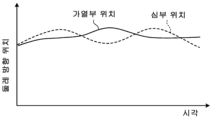
Fig. 17 is an example of a device for detecting the positions of a core part and a heating part of a welded steel pipe according to an embodiment of the present invention, and is a graph showing the positions of the core part and the heating part detected by the position detecting device.
본 발명의 실시형태에 관련된 용접 강관의 심부 및 가열부의 위치 검출 장치, 용접 강관의 제조 설비, 용접 강관의 심부 및 가열부의 위치 검출 방법, 용접 강관의 제조 방법 및 용접 강관의 품질 관리 방법에 대해서, 도면을 참조하면서 설명한다.About the position detection device of the core part and the heating part of a welded steel pipe, the manufacturing equipment of a welded steel pipe, the position detection method of the core part and the heating part of a welded steel pipe, the manufacturing method of a welded steel pipe, and the quality control method of a welded steel pipe according to the embodiment of the present invention, It demonstrates referring drawings.
[용접 강관의 제조 설비와 제조 방법][Manufacturing equipment and manufacturing method of welded steel pipe]
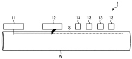
먼저, 용접 강관의 제조 설비의 구성에 대해서, 도 1 을 참조하면서 설명한다. 아울러, 용접 강관의 제조 방법에 대해서도 설명한다. 제조 설비 (1) 는, 용접기 (11) 와, 절삭기 (12) 와, 복수의 어닐러 가열자 (13) 로 이루어지는 가열 장치를 구비하고 있다.First, the configuration of manufacturing facilities for welded steel pipes will be described with reference to FIG. 1 . In addition, the manufacturing method of a welded steel pipe is also demonstrated. The
용접기 (11) 는, 통상으로 성형된 강판의 맞댐부를 용접한다 (용접 공정). 절삭기 (12) 는, 용접기 (11) 에 의한 용접 후에 형성된 용접 강관 (W) 의 비드부 (B) 를 절삭한다 (절삭 공정). 복수의 어닐러 가열자 (13) 는, 절삭기 (12) 에 의한 절삭 후의 심부 (S) 를 표적으로 하여 가열한다 (가열 공정).The
또한, 도 1 에서는 설치의 일례로서 복수의 어닐러 가열자 (13) 의 경우를 나타내고 있지만, 어닐러 가열자 (13) 를 1 개만 설치하는 것도 가능하다. 여기에서, 본 명세서에서는, 가열 공정 중 또는 가열 공정 후에, 심부 (S) 를 표적으로 하여 가열한 결과 발생되는, 고온이 된 영역을 가열부로 부르기로 한다. 가열부는 고온 때문에, 적열 광 혹은 적외광을 발하고 있다.In addition, although FIG. 1 shows the case of
통상적으로 어닐러 가열자 (13) 가 심부 (S) 에 맞는 위치에 있으면, 심부 (S) 와 가열부는 일치한다. 그러나, 1 개 또는 복수의 어닐러 가열자 (13) 의 위치가 어긋나 있는 경우에는, 그 어긋남량만 심부 (S) 로부터 벗어나 가열하게 된다. 바꾸어 말하면, 심부 (S) 만이 아니고, 심부 (S) 근방도 함께 가열하게 된다. 또, 어닐러 가열자 (13) 의 어긋남량이 큰 경우에는, 심부 (S) 로부터 완전히 벗어나, 심부 (S) 근방만을 가열하게 된다. 따라서, 가열부는, 실제로는 심부 및/또는 심부 근방이 가열 공정에서 가열됨으로써 발생된다고도 말할 수 있다.Normally, when the
[위치 검출 장치와 위치 검출 방법][Location detection device and position detection method]
다음으로, 본 발명의 실시형태에 관련된 용접 강관의 심부 및 가열부의 위치 검출 장치와 위치 검출 방법에 대해서, 도 2 를 참조하면서 설명한다. 위치 검출 장치 (2) 는, 어닐러 가열자 (13) 에 의한 가열 중 또는 가열 후에 있어서, 용접 강관 (W) 의 심부 (S) 의 위치와, 어닐러 가열자 (13) 에 의해서 심부 (S) 가 표적으로 하여 가열됨으로서 발생되는 가열부의 위치를 검출한다 (위치 검출 공정). 여기에서, 심부 (S) 및 가열부의 위치는, 어느 쪽이나 용접 강관 (W) 의 표면 상에서의 위치가 된다. 위치 검출 장치 (2) 는, 복수의 어닐러 가열자 (13) 를 구비하는 제조 설비 (1) 에 적용되는 경우, 어느 하나의 어닐러 가열자 (13) 의 뒤에 설치되면 된다. 또, 위치 검출 장치 (2) 는, 광원 (21) 과, 촬상 장치 (22) 와, 화상 처리 장치 (23) 와, 표시 장치 (24) 를 구비하고 있다. 또, 위치 검출 장치 (2) 는, 용접 강관 (W) 의 외부로부터, 당해 용접 강관 (W) 의 표면 상에 있어서의 심부 (S) 의 위치와 가열부의 위치를 측정한다. 이 위치 검출 공정은, 어닐러 가열자 (13) 에 의한 가열 중 또는 가열 후에 있어서 행해지는 점에서, 가열 공정 중에 행해지게 된다. 바꿔 말하면, 위치 검출 공정은 가열 공정에 포함된다.Next, a position detection device and a position detection method of a core part and a heating part of a welded steel pipe according to an embodiment of the present invention will be described with reference to FIG. 2 . The
광원 (21) 은, 용접 강관 (W) 의 관 외측에 배치되고, 용접 강관 (W) 의 심부 (S) 및 가열부에, 제 1 파장역의 광을 조사한다. 제 1 파장역은, 후기하는 제 2 파장역과 간섭하지 않는 파장역이다. 통상적으로 어닐러 가열자 (13) 에 의해서 가열되는 온도는, 최대 1100 ℃ 정도이고, 이 제 1 파장역으로는, 예를 들어 550 ㎚ 이하의 파장역이, 1100 ℃ 의 자발광으로 감도가 거의 없고, 자발광의 영향을 받지 않는다는 이유에서 바람직하다. 특히 바람직한 것이, 일반적으로 컬러 카메라의 파랑 채널이나 초록 채널의 파장역인 450 ㎚ ∼ 550 ㎚ 의 범위이다. 또, 광원 (21) 으로는, 구체적으로는 청색 광원이나 녹색 광원을 사용하는 것이 바람직하다.The
또, 여기에서 설명하는 청색 광원이나 녹색 광원은, LED 광원을 사용해도 된다. 또, 메탈 할라이드 광원, 크세논 광원, 할로겐 광원 등의 광대역의 광원에 대해서, 청색이나 녹색만을 투과시키는 필터 및 필름을 사용해도 된다. 또한, 청색이나 녹색의 파장을 갖는 레이저 광원 앞에, 확산판 등의 광선을 확산시키는 성질을 갖는 광학 소자를 놓음으로써, 해당 부위를 조사 가능한 광원을 사용해도 된다.In addition, you may use LED light sources for the blue light source or green light source demonstrated here. Further, a filter and a film that transmits only blue or green may be used for a broadband light source such as a metal halide light source, a xenon light source, or a halogen light source. In addition, a light source capable of irradiating the part may be used by placing an optical element having a property of diffusing light rays, such as a diffusion plate, in front of a laser light source having a blue or green wavelength.
촬상 장치 (22) 는, 용접 강관 (W) 의 관 외측에 배치되고, 광원 (21) 에 의해서 광이 조사된 용접 강관 (W) 의 심부 (S) 및 가열부를 촬상한다. 여기에서 촬상하는 촬상 영역은, 정확하게 심부 (S) 와 가열부뿐일 필요는 없고, 측정하고자 하는 심부 (S) 와 가열부를 포함하고 있다면, 더욱 넓은 영역이어도 된다. 단, 지나치게 넓으면 실제의 계측에 사용하지 않는 영역이 증가하고, 카메라의 소자수가 유한하기 때문에, 1 화소당 분해능이 저하된다. 또, 지나치게 좁으면, 가열부나 심부 (S) 의 변동이나 강관 직경의 변화에 의해서, 대상이 되는 가열부나 심부 (S) 가 시야 영역으로부터 벗어나 버려, 계측 불능이 된다. 따라서, 촬상 범위를 안정적으로 가열부나 심부 (S) 를 촬상할 수 있는 범위 내에서, 가능한 한 고분해능으로 하는 것이 바람직하다. 촬상 장치 (22) 는, 복수의 상이한 채널을 갖고 있고, 적어도 제 1 채널 및 제 2 채널을 갖고 있다.The
제 1 채널은, 광원 (21) 에 의해서 조사되는 제 1 파장역의 반사광을 수광 가능한 채널이다. 또, 제 2 채널은, 용접 강관 (W) 의 심부 (S) 의 적열에 의해서 발생되는 방사광에 대응하는 제 2 파장역의 반사광을 수광 가능한 채널이다. 그 때문에, 이 제 2 파장역으로는, 예를 들어 600 ㎚ 이상의 파장역이 바람직하다. 특히, 600 ㎚ ∼ 1000 ㎚ 의 범위로 하면, 통상적으로 저렴하게 입수 가능한 Si 소자의 감도 범위 내이기 때문에, 더욱 바람직하다.The first channel is a channel capable of receiving the reflected light of the first wavelength range irradiated by the
촬상 장치 (22) 로서, 앞서 설명한 제 1 파장역을 수신할 수 있는 제 1 채널과, 제 2 파장역을 수신할 수 있는 제 2 채널을 구비하는 촬상 장치를 사용한다. 촬상 장치 (22) 로는, 예를 들어, 적색 채널, 청색 채널 및 녹색 채널을 갖는 컬러 카메라를 사용하는 것이 바람직하다. 이 경우, 제 1 채널은 청색 채널과 녹색 채널, 제 2 채널은 적색 채널에 상당한다. 가열 공정 등에 있어서의 어닐링의 가열 온도는, 예를 들어 800 ∼ 1100 ℃ 이고, 적열에 의한 방사광에 대한 청색 채널 (예를 들어 450 ㎚ 전후의 파장대의 광) 의 수광 감도는 거의 0 이다. 한편, 적색 채널 (예를 들어 650 ㎚ 전후의 파장대의 광) 에서는, 적열에 의한 방사광에 대해서 충분한 수광 감도를 갖고 있다.As the
그 때문에, 상기한 광원 (21) 으로서, 청색 채널의 수광 감도가 되는 파장역을 갖는 청색 광원을 사용하고, 촬상 장치 (22) 로서, 컬러 카메라를 사용한다. 그리고, 광원 (21) 에 의해서 대상의 용접 강관 (W) 에 있는 가열되어 적열 상태의 심부 (S) 를 조사하고, 촬상 장치 (22) 에 의해서 광원 (21) 에 의해서 조사된 심부 (S) 및/또는 심부 (S) 근방을 촬상한다. 이로써, 광학적으로 위치 맞춤된 상태에서, 적색 채널에는 적열에 의한 방사광만을 수광시키고, 청색 채널에는 청색 광원의 반사광만을 수광시키는 것이 가능해진다.Therefore, as the above-mentioned
이와 같이, 용접 강관 (W) 의 심부 (S) 를 육안으로 확인할 수 있는 투수광의 광학계를 사용함으로써, 심부 (S) 의 반사 화상을, 가열에 의한 적열의 방사 화상과 광학적으로 위치 맞춤된 상태에서 취득하는 것이 가능해진다. 또한,「반사 화상」이란, 심부 (S) 에 대해서 광원 (21) 의 광이 반사된 화상의 것을 나타내고 있다. 또,「방사 화상」이란, 심부 (S) 를 표적으로 하여 가열함으로써 발생되는 가열부로부터의 방사광에 의한 화상의 것을 나타내고 있다.In this way, by using an optical system for transmitting and receiving light through which the core portion S of the welded steel pipe W can be visually confirmed, the reflected image of the core portion S is optically aligned with the red-hot radiation image caused by heating, it becomes possible to acquire In addition, the "reflection image" represents an image in which light from the
또한, 광학적으로 위치 맞춤된 상태로 하려면, 방사 화상과 반사 화상을 동축의 광학계에서 취득하는 것이 바람직하다. 또, 촬상 장치 (22) 로서 일반적인 컬러 카메라를 사용함으로써, 위치 검출 장치 (2) 의 저비용화를 도모할 수 있다. 또, 본 실시형태와 같이, 제 1 채널은 1 개 또는 복수의 채널을 갖는 것이 가능하다. 마찬가지로, 제 2 채널도 1 개 또는 복수의 채널을 갖는 것이 가능하다. 또, 제 1 채널과 제 2 채널이 각각 복수 채널을 가질 경우, 채널마다 상이한 파장역에 대해서 감도를 갖고 있어도 되고, 동일한 파장역에 대해서 감도를 갖고 있어도 된다.In addition, in order to achieve an optically aligned state, it is preferable to acquire a radiation image and a reflection image with a coaxial optical system. Moreover, cost reduction of the
촬상 장치 (22) 는, 이차원의 시야를 갖는 것이어도 되고, 혹은 일차원의 시야를 갖는 것이어도 된다. 촬상 장치 (22) 가 일차원의 시야를 가질 경우, 용접 강관 (W) 의 둘레 방향으로 시야를 갖도록 할 필요가 있다.The
여기에서, 본 실시형태에서는, 광원 (21) 으로서 청색 광원을 사용하고, 촬상 장치 (22) 로서 컬러 카메라를 사용하는 것을 전제로 설명한다. 단, 적열에 의한 방사광의 파장역과, 대상의 용접 강관 (W) 에 조사되는 광의 파장역을 분리할 수 있는 구성이면, 상기 이외의 조합이어도 실현될 수 있는 것은 말할 것도 없다.Here, in this embodiment, it demonstrates on the assumption that a blue light source is used as the
또, 용접 강관 (W) 의 반사광으로부터 심부 (S) 를 검출할 때에, 1 세트의 광학계 (청색 광원 및 청색 채널) 만으로는 검출이 곤란한 경우, 예를 들어 제 3 파장역인 녹색 광원과 녹색 채널을 추가하여, 2 가지의 반사 화상을 취득해도 된다. 이 경우, 예를 들어 도 3 에 나타내는 바와 같이, 용접 강관 (W) 의 관축 방향으로 청색 광원 (21A) 및 녹색 광원 (21B) 을 배치한다. 그리고, 이와 함께, 심부 (S) 및 가열부에 대해서, 청색 광원 (21A) 을 정반사 조건이 되도록 배치하고, 녹색 광원 (21B) 을 확산 반사 조건이 되도록 배치할 수 있다.In addition, when detecting the deep portion S from the reflected light of the welded steel pipe W, when detection is difficult with only one set of optical systems (blue light source and blue channel), for example, a green light source and a green channel in the third wavelength range are added. Thus, two reflection images may be acquired. In this case, as shown in FIG. 3, for example, the blue
혹은, 정반사 조건은 아니지만, 도 4 에 나타내는 바와 같이, 용접 강관 (W) 의 둘레 방향의 심부 (S) 에 대해서 서로 대칭이 되는 위치에 청색 광원 (21A) 및 녹색 광원 (21B) 을 배치하고, 2 방향으로부터 광을 조사해도 된다. 이렇게 함으로써, 만약에 가령, 심부 (S) 에 요철이 있었다고 해도, 청색 광원 (21A) 과 녹색 광원 (21B) 에서 조사 방향이 상이하기 때문에 그림자의 방향이 반대가 되고, 화상 처리에 의해서 심부 (S) 를 양호한 정밀도로 검출하는 것이 가능해진다. 또한, 도 3 및 도 4 에 있어서의 청색 광원 (21A) 및 녹색 광원 (21B) 의 위치 관계는, 서로 바뀌여도 된다. 이와 같이, 2 세트의 광학계를 사용함으로써, 심부 (S) 의 검출 정밀도를 향상시킬 수 있다.Alternatively, although it is not a regular reflection condition, as shown in FIG. 4, a blue
(컬러 카메라의 정밀도 및 종류) (precision and type of color camera)
다음으로, 촬상 장치 (22) 로서 사용하는 컬러 카메라의 정밀도 및 종류에 대해서 설명한다. 먼저, 용접 강관 (W) 의 심부 (S) 와 가열부의 위치 맞춤의 요구 정밀도에 대해서, 분해능을 설정할 필요가 있다. 예를 들어 0.5 ㎜ 의 정밀도가 필요하면, 화소 분해능 이상으로 올바르게 위치를 추정하는 것은 곤란하기 때문에, 적어도 0.5 ㎜/화소 이상의 분해능이 필요해진다.Next, the accuracy and type of the color camera used as the
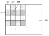
컬러 카메라의 종류로는, 주로 베이어 방식과 프리즘 방식이 존재한다. 베이어 방식은, 예를 들어 도 5 에 나타내는 바와 같이, 각 화소를 구성하는 촬상 소자 (221) 앞에, 각 색의 필터 (빨강 필터 (222), 초록 필터 (223), 파랑 필터 (224)) 를 균등하게 배치하고, 화상을 취득한다. 그리고, 그 중에서 각 채널의 화상으로 분리하면, 각 채널은 각 색의 필터가 존재하는 화소만 화소값이 얻어지고, 그 밖에는 이가 빠진 것과 같은 상태가 된다. 따라서, 업 샘플링 처리에 의해서 다른 색의 필터의 화소값을 보완함으로써, 3 채널분의 화상을 생성할 수 있다. 베이어 방식은, 간이한 구성으로 실현할 수 있기는 하지만, 얻어진 화상만큼의 분해능이 없고, 각 채널도 소자 사이즈 오더로 위치가 어긋난다는 특징이 있다.As types of color cameras, there are mainly a Bayer method and a prism method. In the Bayer method, for example, as shown in FIG. 5 , filters of each color (
한편, 프리즘 방식은, 도 6 에 나타내는 바와 같이, 적색용, 녹색용 및 청색용의 3 장의 촬상 소자 (221) 를 준비하고, 그것을 프리즘 (225) 에 의해서 엄밀하게 위치 맞춤하면서, 색을 분리한다. 이와 같은 기능을 갖는 프리즘 (225) 을,「다이크로익 프리즘」이라고 부른다. 프리즘 방식은, 베이어 방식과 같은 업 샘플링이 불필요하고, 서브 픽셀 이하의 정밀도로 각 채널간의 위치 정밀도를 보일 수 있기 때문에, 베이어 방식과 비교하여 높은 계측 정밀도가 얻어진다는 특징이 있다.On the other hand, in the prism method, as shown in FIG. 6 , three
(광원 및 촬상 장치의 배치) (arrangement of light source and imaging device)
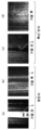
다음으로, 용접 강관 (W) 의 심부 (S) 의 화상을 촬상하기 위한 광원 (21) 및 촬상 장치 (22) 의 적절한 배치 위치에 대해서 설명한다. 도 7 은, 심부 (S) 의 어닐링 전후에 있어서의 화상이고, (a) 는 가열 전에 정반사 조건에서 촬상한 화상, (b) 는 가열 후에 정반사 조건에서 촬상한 화상, (c) 는 가열 전에 확산 반사 조건에서 촬상한 화상, (d) 는 가열 후에 확산 반사 조건에서 촬상한 화상이다. 정반사 조건에서 촬상하는 경우, 주로 정반사광을 수광한 화상이 얻어지고, 확산 반사 조건에서 촬상하는 경우, 주로 확산 반사광, 즉 산란광을 수광한 화상이 얻어진다.Next, appropriate arrangement positions of the
상기한 바와 같이, 비드부 (B) 를 절삭한 직후의 심부 (S) 는, 경면성이 매우 높다. 이 상태에서 어닐링이 행해지면, 표면에 산화 피막 (흑피 산화 피막) 이 생성된다. 그리고, 가열을 행함으로써 산화 피막의 부착량이 증대되고, 이 산화 피막의 부착량에 따라서 표면 조도가 증가하며, 그 결과, 심부 (S) 의 경면성은 저하되고, 확산성은 높아져 간다.As described above, the core portion S immediately after cutting the bead portion B has very high mirror finish. When annealing is performed in this state, an oxide film (mite oxide film) is formed on the surface. Then, by heating, the amount of the oxide film deposited increases, and the surface roughness increases according to the amount of the oxide film deposited.
정반사 조건에서 촬상했을 경우, 가열 전의 경면성이 높은 상태에서는, 예를 들어 도 7(a) 에 나타내는 바와 같이, 심부 (S) 가 그 밖의 부분보다 밝게 비쳐 보인다. 한편, 가열 후에는 산화 피막의 부착에 의해서 경면성이 저하되고 확산성이 높아지기 때문에, 예를 들어 동 도면의 (b) 에 나타내는 바와 같이, 산화 피막의 부착량에 따라서, 심부 (S) 가 그 이외의 부분과 비교하여 어둡게 비쳐 보인다. 이와 같이, 정반사 조건에서 촬상했을 경우, 가열 전후에 있어서 휘도의 차가 크기 때문에, 심부 (S) 의 비쳐 보이는 것에도 현저한 차가 발생된다.When imaging under regular reflection conditions, in a state with high mirror surface before heating, as shown in Fig. 7(a), for example, the core portion S appears brighter than the other portions. On the other hand, after heating, the adherence of the oxide film reduces the mirror surface property and increases the diffusivity. Therefore, as shown in (b) of the same figure, for example, depending on the amount of oxide film deposited, the core portion S is It looks dark compared to the part of . Thus, since the difference in luminance before and after heating is large when imaging under regular reflection conditions, a remarkable difference also arises in the transparency of the core part S.
확산 반사 조건에서 촬상했을 경우, 가열 전의 경면성이 높은 상태에서는, 예를 들어 도 7(c) 에 나타내는 바와 같이, 심부 (S) 가 그 밖의 부분보다 어둡게 비쳐 보인다. 한편, 가열 후에는, 예를 들어 동 도면의 (d) 에 나타내는 바와 같이, 심부 (S) 와 그 밖의 부분의 구별이 잘 되지 않게 된다. 이와 같이, 확산 반사 조건에서 촬상했을 경우, 정반사 조건에서 촬상했을 경우만큼, 심부 (S) 의 비쳐 보이는 것에도 현저한 차는 발생되지 않는다.When imaging under diffuse reflection conditions, in a state with high specularity before heating, as shown in FIG. 7(c), for example, the core portion S appears darker than the other portions. On the other hand, after heating, as shown, for example, in (d) of the same figure, distinction between the core portion S and other portions becomes difficult. In this way, when imaging is performed under diffuse reflection conditions, no significant difference occurs in the transparency of the deep portion S as much as when imaging is performed under regular reflection conditions.
심부 (S) 및 그 밖의 부분에 있어서의 산화 피막의 부착량과 정반사 휘도의 관계, 심부 (S) 및 그 밖의 부분에 있어서의 산화 피막의 부착량과 확산 반사 휘도의 관계를 정리하면, 각각 도 8(a), (b) 와 같이 된다.Summarizing the relationship between the amount of oxide film deposited on the deep portion S and other portions and the regular reflection luminance, and the relationship between the amount of oxide film deposited on the deep portion S and other portions and diffuse reflection luminance, Fig. 8( a) and (b).
도 8(a) 는, 산화 피막의 부착량과 정반사 휘도의 관계를 모식화하여 나타내고 있다. 도 8(a) 에 있어서, 실선은 심부 (S) 의 정반사 휘도의 변화, 파선은 심부 (S) 이외의 정반사 휘도의 변화, 가로축은 심부 (S) 에 있어서의 산화 피막의 부착량, 세로축은 정반사 휘도를 나타내고 있다. 한편, 도 8(b) 는, 산화 피막의 부착량과 확산 반사 휘도의 관계를 모식화하여 나타내고 있다. 도 8(b) 에 있어서, 실선은 심부 (S) 의 확산 반사 휘도의 변화, 파선은 심부 (S) 이외의 확산 반사 휘도의 변화, 가로축은 심부 (S) 에 있어서의 산화 피막의 부착량, 세로축은 확산 반사 휘도를 나타내고 있다. 또, 도 8(a) 와 (b) 에서, 동일한 부착량에 대해서는 동일한 가로축의 위치가 되도록, 가로축의 위치를 대체로 맞추어 놓고 있다. 또, 세로의 일점 쇄선은, 심부 (S) 의 산화 피막이 동일 부착량이 되는, 어느 시점을 나타내고 있다.Fig. 8(a) schematically shows the relationship between the amount of oxide film deposited and the regular reflection luminance. In Fig. 8(a), the solid line indicates the change in regular reflection luminance of the core part S, the broken line indicates the change in regular reflection luminance other than the deep part S, the abscissa indicates the amount of oxide film deposited in the core part S, and the vertical axis indicates the specular reflection. indicates luminance. On the other hand, Fig. 8(b) schematically shows the relationship between the amount of oxide film deposited and the diffuse reflection luminance. In Fig. 8(b), the solid line indicates the change in diffuse reflection luminance of the core portion S, the broken line indicates the change in diffuse reflection luminance of areas other than the core portion S, the horizontal axis indicates the amount of oxide film deposited in the core portion S, and the vertical axis represents the diffuse reflection luminance. In addition, in Fig. 8(a) and (b), the positions of the horizontal axes are generally aligned so that the positions of the horizontal axes are the same for the same amount of deposition. In addition, the vertical one-dotted chain line has shown a certain point in time when the oxide film of the core part S becomes the same amount of deposition.
정반사 조건의 화상에서는, 심부 (S) 에 산화 피막이 별로 부착되어 있지 않은 경우, 즉 도 8(a) 의 가로축에 대해서 좌측은 심부 (S) 가 심부 (S) 이외의 것과 비교하여 밝아진다. 그리고 그 후, 산화 피막의 부착량이 증가함에 따라서, 심부 (S) 의 휘도가 저하되고, 최종적으로는 심부 (S) 이외의 것과 비교하여 어두워진다. 한편, 확산 반사 조건의 화상에서는, 심부 (S) 에 산화 피막이 별로 부착되어 있지 않은 경우, 즉 도 8(b) 의 가로축에 대해서 좌측은 심부 (S) 가 심부 (S) 이외의 것과 비교하여 어두워진다. 그리고 그 후, 산화 피막의 부착량이 증가함에 따라서, 심부 (S) 의 휘도가 높아지고, 최종적으로는 심부 (S) 이외의 것과 구별이 잘 되지 않게 되어 간다.In the image under the regular reflection condition, when the oxide film is not adhered to the deep portion S, that is, the deep portion S on the left side of the horizontal axis in FIG. And after that, as the amount of deposition of the oxide film increases, the luminance of the core portion S decreases, and finally it becomes darker compared to those other than the core portion S. On the other hand, in the image under the diffuse reflection condition, when the oxide film is not adhered to the deep portion S, that is, the deep portion S on the left side of the horizontal axis in FIG. lose After that, as the amount of the oxide film deposited increases, the luminance of the deep portion S increases, and finally, it becomes difficult to distinguish it from anything other than the deep portion S.
단, 산화 피막의 부착량의 정도에 따라서는, 심부 (S) 의 정반사 휘도와 심부 (S) 이외의 정반사 휘도의 차가 작아져, 정반사 휘도에서는 심부 (S) 의 검출은 곤란해질 가능성이 있다. 이것은, 도 8(a) 중에 있어서는 원 표시 (●) 로 나타낸 상태이다. 이 때의 도 8(a) 와 동일한 산화 피막의 부착량 (일점 쇄선으로 도시) 에 있어서, 도 8(b) 의 확산 반사 조건에서는, 심부 (S) 의 확산 반사 휘도는 원 표시 (●), 심부 (S) 이외의 확산 반사 휘도는 엑스 표시 (×) 가 된다. 그 때문에, ● 표시와 × 표시 사이에 확산 반사 휘도의 차가 발생되어 있을 가능성이 높다. 이와 같이, 정반사 휘도에 있어서, 심부 (S) 와 심부 (S) 이외의 휘도의 차가 작아도, 확산 반사 조건에 있어서, 심부 (S) 의 확산 반사 휘도와 심부 (S) 이외의 확산 반사 휘도의 차가 명확하게 발생되어 있으면, 확산 반사 휘도로부터 심부 (S) 의 검출이 가능해진다. 요컨대, 정반사의 정보와 확산 반사의 정보를 조합하면, 심부 (S) 의 검출이 보다 확실해져, 보다 바람직하다.However, depending on the degree of deposition of the oxide film, the difference between the regular reflection luminance of the deep part S and the regular reflection luminance of other parts of the deep part S becomes small, and detection of the deep part S may be difficult with the regular reflection luminance. This is a state indicated by a circle mark (●) in Fig. 8(a). Under the diffuse reflection condition of FIG. 8(b), under the diffuse reflection condition of FIG. Diffuse reflection luminance other than (S) is marked with an X (x). Therefore, there is a high possibility that a difference in diffuse reflection luminance has occurred between the mark ● and the mark x. In this way, in the regular reflection luminance, even if the difference between the luminance of the deep portion S and the luminance other than the deep portion S is small, in the diffuse reflection condition, the difference between the diffuse reflection luminance of the deep portion S and the diffuse reflection luminance of the other than the deep portion S is If it occurs clearly, the deep portion S can be detected from the diffuse reflection luminance. In short, combining information of regular reflection and information of diffuse reflection makes detection of the deep portion S more reliable, which is more preferable.
정반사의 정보와 확산 반사의 정보를 조합하여 심부 (S) 의 위치를 검출하는 플로 차트의 일례를, 도 9 에 나타낸다. 먼저, 정반사 조건에 있어서, 심부 (S) 와 심부 (S) 이외의 부분을 비교하여, 정반사 휘도에 차가 있는지의 여부를 판정한다 (스텝 S1). 정반사 휘도에 차가 있고, 심부 (S) 를 검출할 수 있을 경우 (스텝 S1 에서 Yes), 정반사 화상의 휘도차를 이용하여 임계값 처리 등에 의해서 심부 (S) 를 산출한다 (스텝 S2). 한편, 정반사 휘도에 차가 없고, 심부 (S) 를 검출할 수 없을 경우 (스텝 S1 에서 No), 심부 (S) 가 확산 반사의 휘도치로 밝게 또는 어둡게 보이는 것을 이용하여 심부 (S) 를 산출한다 (스텝 S3). 이와 같이 하면, 임계값 처리 등에 의해서 산화 피막의 부착에 의존하지 않고 심부 (S) 를 안정적으로 검출할 수 있다. 또한, 도 9 는, 심부 (S) 를 안정적으로 검출하기 위한 플로 차트의 일례이다. 단, 본 예와 관계없이, 정반사 화상과 확산 반사 화상으로부터, 사칙 연산, 임계값 처리, AND 처리, OR 처리, 또는 이들 처리의 조합 등을 사용하여 직접 심부 (S) 를 추출해도 된다.Fig. 9 shows an example of a flow chart for detecting the position of the deep portion S by combining information of regular reflection and information of diffuse reflection. First, under the regular reflection condition, the deep part S is compared with the part other than the deep part S, and it is determined whether or not there is a difference in regular reflection luminance (step S1). If there is a difference in regular reflection luminance and the deep part S can be detected (Yes in step S1), the deep part S is calculated by threshold value processing or the like using the luminance difference of the regular reflection image (step S2). On the other hand, when there is no difference in regular reflection luminance and the deep portion S cannot be detected (No in step S1), the deep portion S is calculated using the fact that the deep portion S looks bright or dark with the luminance value of diffuse reflection ( Step S3). In this way, the deep portion S can be stably detected by threshold processing or the like without depending on the adhesion of the oxide film. 9 is an example of a flow chart for stably detecting the core portion S. However, regardless of this example, the deep portion S may be directly extracted from the regular reflection image and the diffuse reflection image using four arithmetic operations, threshold processing, AND processing, OR processing, or a combination of these processing.
이상을 기초로 하여, 제 1 파장역의 광을 조사하는 광원 (21) (본 실시형태에서는 청색 광원) 과, 제 1 채널을 갖는 촬상 장치 (22) (본 실시형태에서는 컬러 카메라) 를, 심부 (S) 를 포함하는 측정 지점 c 에 대해서, 정반사 조건이 되도록 배치하는 것이 바람직하다. 예를 들어, 관축 방향으로 배치하는 경우에서는, 광원 (21) 및 촬상 장치 (22) 를, 도 2 에 나타내는 바와 같이 설치하는 것이 바람직하다. 이 경우에는, 광원 (21) 및 촬상 장치 (22) 를, 용접 강관 (W) 의 심부 (S) 를 포함하는 측정 지점 c 의 법선 벡터 n 에 대해서, 광원 (21) 에 의한 광의 조사 각도 α 와 촬상 장치 (22) 에 의한 광의 수광 각도 β 가 동등해지는 위치에 각각 설치하는 것이 바람직하다. 이로써, 어닐링 전후에 있어서, 심부 (S) 를 양호한 정밀도로 검출할 수 있다. 또한, 심부 (S) 를 적절히 검출할 수 있다면, 광원 (21) 및 촬상 장치 (22) 를 상기한 배치 이외로 해도 되는 것은 말할 것도 없다. 이하, 위치 검출 장치 (2) 의 구성의 설명으로 되돌아간다.Based on the above, a light source 21 (blue light source in this embodiment) that emits light in the first wavelength range and an imaging device 22 (color camera in this embodiment) having a first channel are Regarding the measurement point c including (S), it is preferable to arrange it so that it may become a regular reflection condition. For example, in the case of arranging in the tube axis direction, it is preferable to install the
화상 처리 장치 (23) 는, 촬상 장치 (22) 에 의해서 촬상된 화상을, 주지의 화상 처리 기술에 의해서 처리하여, 용접 강관 (W) 의 심부 (S) 의 위치 및 가열부의 위치 (양자의 위치 관계) 를 각각 검출한다. 또, 화상 처리 장치 (23) 는, 검출된 심부 (S) 및 가열부의 위치에 더하여, 심부 (S) 의 위치에 대한 가열부의 위치의 어긋남량을 검출 (산출) 해도 된다. 또한, 상기한「어긋남량」이란, 구체적으로는 용접 강관 (W) 의 둘레 방향에 있어서의 어긋남량의 것을 나타내고 있다.The image processing device 23 processes the image captured by the
여기에서, 촬상 장치 (22) 의 적색 채널에서 얻어지는 가열부의 화상은, 도 10 에 나타내는 휘도 프로파일과 같이, 가열부의 위치가 고휘도로 되어 있다. 그 때문에, 고휘도가 되는 위치를 산출함으로써, 가열부의 위치를 검출할 수 있다. 가열부의 위치는, 예를 들어 폭 방향의 무게 중심 위치, 최고 휘도가 되는 위치, 임계값 처리에 의한 2 치화 후 중심 위치나 무게 중심 위치 등에 기초하여 검출할 수 있다.Here, in the image of the heating part obtained in the red channel of the
또, 촬상 장치 (22) 의 청색 채널에서 얻어지는 용접 강관 (W) 의 정반사 화상은, 표면의 산화 피막의 부착량이 적을 때에는 밝게 보이고 (도 7(a) 참조), 산화 피막이 충분히 부착되어 있을 때에는 어둡게 보인다 (동 도면의 (b) 참조). 따라서, 적색 채널의 경우와 동일한 생각에 의해서, 밝아지는 부분의 위치 및 어두워지는 부분의 위치를 산출한다.In addition, the regular reflection image of the welded steel pipe W obtained in the blue channel of the
또한, 화상의 세로 방향 또는 가로 방향과, 용접 강관 (W) 의 반송 방향이 엄밀하게 일치하고 있지 않을 경우, 화상을 회전시키는 등의 전처리를 행하는 것이 바람직하다. 또, 주파수 필터 등에 의해서 고주파 성분을 제거하고, 용접 강관 (W) 의 관축 방향으로 적산·평균화·중앙치 처리를 연산하는 등의 전처리에 의해서 노이즈를 저감시키는 것이 바람직하다.In addition, when the longitudinal direction or transverse direction of the image and the conveying direction of the welded steel pipe W do not strictly match, it is preferable to perform preprocessing such as rotating the image. In addition, it is preferable to reduce noise by preprocessing such as removing high-frequency components with a frequency filter or the like and calculating integration, averaging, and median processing in the tube axis direction of the welded steel pipe W.
또, 화상 처리 장치 (23) 에 의한 화상 처리에 의해서도 심부 (S) 를 양호한 정밀도로 산출하기가 어려우며, 또한 화상을 육안으로 보았을 때 심부 (S) 를 판정할 수 있는 경우에는, 예를 들어 가열부의 화상 및 심부 (S) 의 화상을, 표시 장치 (24) 를 통해서 오퍼레이터에게 시각적으로 표시해도 된다.In addition, when it is difficult to calculate the core portion S with good accuracy even by image processing by the image processing device 23 and the core portion S can be determined by visually viewing the image, for example, heating The negative image and the deep portion S image may be visually displayed to the operator through the
표시 장치 (24) 는, 화상 처리 장치 (23) 에 의한 처리 결과를 표시함으로써, 오퍼레이터에 대해서 가이던스를 행한다. 표시 장치 (24) 는, 예를 들어 화상 처리 장치 (23) 에 의해서 검출된 용접 강관 (W) 의 심부 (S) 의 위치에 대한 가열부의 위치의 어긋남량을 수치로서 표시할 수 있다. 또, 표시 장치 (24) 는, 심부 (S) 의 위치 및 가열부의 위치를, 화상으로서 표시해도 된다.The
심부 (S) 의 위치 및 가열부의 위치를 화상으로서 표시할 경우, 예를 들어 촬상 장치 (22) 의 청색 채널에서 수광한 화상과, 적색 채널에서 수광한 화상을 중첩하여 표시해도 된다. 혹은, 도 11 에 나타내는 바와 같이, 심부 (S) 의 위치를 나타내는 화상과, 가열부의 위치를 나타내는 화상을, 용접 강관 (W) 의 반송 방향으로 나열하여 표시해도 된다. 또, 심부 (S) 의 자동 검출을 양호한 정밀도로 행할 수 없을 경우에는, 예를 들어 도 12 에 나타내는 바와 같이, 어닐러 가열자 (13) 의 위치로부터 추정한 가열부의 위치를, 심부 (S) 상에 중첩하여 표시해도 된다. 이와 같이, 심부 (S) 의 위치 및 가열부의 위치를 화상으로서 표시함으로써, 오퍼레이터가 심부 (S) 의 위치 및 가열부의 위치를, 직감적으로 파악하는 것이 가능해진다.When displaying the position of the core part S and the position of the heating part as an image, for example, an image received in the blue channel of the
또한, 위치 검출 장치 (2) 는, 심부 (S) 의 위치와 가열부의 위치 사이에, 미리 정한 임계값 이상의 거리가 있을 경우에, 알람에 의해서 통지하는 통지 수단을 구비하고 있어도 된다. 또, 위치 검출 장치 (2) 는, 화상 처리 장치 (23) 에 의해서 처리된 화상을 축적하고, 가열 상황의 추이를 기록하는 기록 수단을 구비하고 있어도 된다.In addition, the
[변형예 1][Modification 1]
상기한 위치 검출 장치 (2) 에서는, 용접 강관 (W) 의 심부 (S) 및 가열부의 위치 검출 결과를 표시 장치 (24) 에 표시하고 있었다. 한편, 예를 들어 도 13 에 나타내는 바와 같이, 화상 처리 장치 (23) 에 의해서 검출한 심부 (S) 및 가열부의 위치의 어긋남량에 기초하여, 어닐러 가열자 (13) 의 위치를 제어해도 된다. 동 도면에 나타낸 위치 검출 장치 (2A) 는, 도 2 에 나타낸 위치 검출 장치 (2) 의 구성에 더하여, 가열자 위치 제어 장치 (25) 를 구비하고 있다.In the
가열자 위치 제어 장치 (25) 는, 위치 검출 장치 (2A) 의 화상 처리 장치 (23) 에 의해서 검출된 심부 (S) 의 위치에 대한 가열부의 위치의 어긋남량에 기초하여, 어닐러 가열자 (13) 의 위치를 제어한다. 즉, 가열자 위치 제어 장치 (25) 는, 심부 (S) 에 대해서 가열부를 일치시키도록, 어닐러 가열자 (13) 의 위치를 용접 강관 (W) 의 둘레 방향으로 이동시킨다. 이와 같이, 심부 (S) 의 위치에 대한 가열부의 위치의 어긋남량에 기초하여 어닐러 가열자 (13) 의 위치를 제어함으로써, 심부 (S) 를 양호한 정밀도로 가열하는 것이 가능해진다.The heater position control device 25, based on the amount of displacement of the position of the heating part with respect to the position of the core part S detected by the image processing device 23 of the
또, 어닐러 가열자 (13) 가 복수 있을 경우에는, 본 발명에 관련된 위치 검출 장치 (2A) 보다 전 및/또는 후에 있는 어닐러 가열자 (13) 의 위치를 제어할 수 있다. 위치 검출 장치 (2A) 보다 전에 있는 어닐러 가열자 (13) 의 위치를 제어하는 경우에는, 피드 백이 되어, 안정적인 가열 공정의 제어가 가능해진다. 한편, 위치 검출 장치 (2A) 보다 후에 있는 어닐러 가열자 (13) 의 위치를 제어하는 경우에는, 피드 포워드가 되어, 보다 반응이 좋은 제어가 됨과 함께, 어긋나 가열된 심부 (S) 도, 위치 검출 장치 (2A) 보다 후에서는 올바르게 가열되게 된다. 보다 바람직한 것은, 위치 검출 장치 (2A) 의 전후에 있는 어닐러 가열자 (13) 의 위치를 제어하는 것이고, 피드 백과 피드 포워드의 양방의 이점을 얻을 수 있다. 또, 가장 바람직한 것은, 위치 검출 장치 (2A) 의 전후에 있는 모든 어닐러 가열자 (13) 의 위치를 제어하는 것이고, 목적으로 하는 가열 공정에서의 효과가, 보다 확실하게 얻어지는 것이 된다.Moreover, when there are a plurality of
또, 용접 강관 (W) 이 가열 과정에서 비틀려, 각 어닐러 가열자 (13) 의 위치마다 심부 (S) 의 위치가 상이한 경우에는, 반대로 위치 검출 장치 (2A) 를 각 어닐러 가열자 (13) 의 전후에 복수 설치하는 것이 바람직하다. 이와 같이 배치함으로써, 어닐러 가열자 (13) 마다의 가열부와 심부 (S) 의 위치 관계를 파악할 수 있게 되어, 비틀림이 발생되었다고 해도 위치 제어 성능이 향상된다. 보다 많은 위치 검출 장치 (2A) 를 설치하는 것이 바람직하지만, 가장 바람직한 것은, 모든 어닐러 가열자 (13) 의 전후에서 가열부와 심부 (S) 의 위치 관계를 파악하는 것이고, 비틀림의 영향을 완전히 제외하는 것이 가능해진다.In addition, when the welded steel pipe W is twisted in the heating process and the position of the core part S is different for each position of each
[변형예 2][Modification 2]
본 발명의 변형예 2 에 대해서 설명한다. 변형예 2 에서는, 도 14 에 나타내는 바와 같이, 컬러 카메라 대신에, 동일한 광학 특성을 갖는 2 대의 카메라 (31, 32) 와, 빔 스플리터 (41) 를 사용한다. 또한, 빔 스플리터 (41) 대신에 프리즘을 사용해도 된다. 그리고, 2 대의 카메라 (31, 32) 에 대해서, 빔 스플리터 (41) 를 사용하여 광축 맞춤을 행하여, 대상 시야가 동일해지도록 조정한다.
여기에서 설명하는 광학 특성이란, 시야 및 분해능을 가리킨다. 각 카메라 (31, 32) 앞에는, 예를 들어 제 1 파장역만을 투과하는 필터와, 제 2 파장역만을 투과하는 필터를 설치한다. 이로써, 위치 맞춤된 상태에서 반사 화상과 방사 화상을 얻는 것이 가능해져, 컬러 카메라를 사용한 경우와 동일한 효과를 얻을 수 있다. 또 이 때, 광축의 어긋남이나 렌즈의 셰이딩에 의해서 다소의 위치 어긋남이 발생해도, 예를 들어 화상간에서 촬상 대상의 동일 위치가 되도록 소자간의 대응이 미리 판명되어 있을 경우, 화상 처리에 의해서 위치 맞춤해도 된다. 또, 빔 스플리터 (41) 나 프리즘 대신에, 파장역에 의해서, 반사 방향을 제어하거나, 투과시키거나 하는 특성을 갖는 다이크로익 미러를 사용해도 된다.The optical properties described here refer to visual field and resolution. In front of each of the
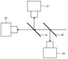
또, 예를 들어 3 대의 카메라 (31, 32, 33) 를 사용하여, 2 조건의 반사 화상을 촬상할 경우, 도 15 에 나타내는 바와 같이, 2 대의 빔 스플리터 (41, 42) 를 사용하여 광축 맞춤을 행함으로써, 컬러 카메라를 사용한 경우와 동일한 효과를 얻을 수 있다.In addition, for example, when taking a reflection image under two conditions using three
[변형예 3][Modification 3]
본 발명의 변형예 3 에 대해서 설명한다. 변형예 3 에서는, 도 16 에 나타내는 바와 같이, 컬러 카메라 (34) 와, 하프 미러 (43) 를 사용한다. 예를 들어 배치 제약에 의해서, 어닐러 가열자 (13) 간에 거의 미미한 스페이스밖에 없을 경우, 후기하는 실시예와 같이, 정반사 조건이나 확산 반사 조건에서 조사하는 것이 곤란하다.Modification 3 of the present invention will be described. In the modified example 3, as shown in Fig. 16, a
그래서, 이와 같은 경우에는, 도 16 에 나타내는 바와 같은 동축 낙사 광학계를 채용해도 된다. 즉, 하프 미러 (43) 를 개재하여, 제 1 파장역의 광선을 용접 강관 (W) 의 표면에 조사하고, 그 반사광을 하프 미러 (43) 에 투과시켜, 컬러 카메라 (34) 에 의해서 수광한다. 또, 제 2 파장역의 광은, 하프 미러 (43) 를 개재하여 수광할 수 있기 때문에, 반사광의 수광, 자발광의 수광 및 조사를, 동축에서 실시하는 것이 가능해져, 스페이스 절약화를 기대할 수 있다.Therefore, in such a case, a coaxial falling optical system as shown in Fig. 16 may be employed. That is, light rays in the first wavelength range are irradiated to the surface of the welded steel pipe W through the
[품질 관리 방법][Quality control method]
용접 강관 (W) 의 품질 관리 방법은, 위치 검출 장치 (2, 2A) 에 의해서 검출된 심부 (S) 의 위치에 대한 가열부의 위치의 어긋남량에 기초하여, 용접 강관 (W) 의 품질을 관리한다. 품질 관리 방법에서는, 예를 들어 상기한 어긋남량이 미리 정한 임계값 이상인 경우, 용접 강관 (W) 의 품질 (예를 들어 인성 등) 이, 미리 정해진 요구 스펙을 만족하는지의 여부를 검사하는 검사 공정을 실시한다. 그리고, 검사 공정의 결과에 기초하여, 당해 용접 강관 (W) 을 그레이드 하향으로 하여 재이용할지, 혹은 NG 품으로서 폐기할지를 결정한다. 이와 같이, 심부 (S) 의 위치에 대한 가열부의 위치의 어긋남량에 기초하여 용접 강관 (W) 을 분류함으로써, 품질이 우수한 용접 강관 (W) 을 제공할 수 있다.The quality control method of the welded steel pipe W controls the quality of the welded steel pipe W based on the displacement amount of the position of the heating part relative to the position of the core part S detected by the
이상 설명한 실시형태에 관련된 용접 강관의 심부 및 가열부의 위치 검출 장치, 용접 강관의 제조 설비, 용접 강관의 심부 및 가열부의 위치 검출 방법, 용접 강관의 제조 방법 및 용접 강관의 품질 관리 방법에 의하면, 아래와 같은 효과를 얻는다. 즉, 광원 (21) 으로부터 심부 (S) 에 조사된 광의 반사광을 수광하는 채널과, 가열부의 적열에 의한 방사광을 수광하는 채널을 갖는 촬상 장치 (22) 에 의해서 용접 강관 (W) 을 촬상함으로써, 저비용이며 또한 간이한 구성으로 할 수 있다. 또, 심부 및 가열부의 위치를 양호한 정밀도로 검출할 수 있다.According to the position detection device of the core part and the heating part of the welded steel pipe, the manufacturing facility of the welded steel pipe, the method of detecting the position of the core part and the heating part of the welded steel pipe, the manufacturing method of the welded steel pipe, and the quality control method of the welded steel pipe according to the above-described embodiment, the following get the same effect That is, by imaging the welded steel pipe W by the
또, 실시형태에 관련된 용접 강관의 심부 및 가열부의 위치 검출 장치, 용접 강관의 제조 설비, 용접 강관의 심부 및 가열부의 위치 검출 방법, 용접 강관의 제조 방법 및 용접 강관의 품질 관리 방법에 의하면, 아래와 같은 효과도 얻는다. 즉, 종래 오퍼레이터에 의한 실물의 육안에 의존하고 있던 심부 (S) 와 가열부의 위치 관계의 위치 어긋남 방지 대책을, 가시화 및 자동화하는 것이 가능해진다.In addition, according to the position detection device of the core part and the heating part of the welded steel pipe, the manufacturing equipment of the welded steel pipe, the method of detecting the position of the core part and the heating part of the welded steel pipe, the manufacturing method of the welded steel pipe, and the quality control method of the welded steel pipe according to the embodiment, the following get the same effect That is, it becomes possible to visualize and automate the countermeasures for preventing the positional deviation of the positional relationship between the core part S and the heating part, which have conventionally been dependent on the operator's visual observation of the real thing.
이상, 본 발명에 관련된 용접 강관의 심부 및 가열부의 위치 검출 장치, 용접 강관의 제조 설비, 용접 강관의 심부 및 가열부의 위치 검출 방법, 용접 강관의 제조 방법 및 용접 강관의 품질 관리 방법에 대해서, 발명을 실시하기 위한 형태 및 실시예에 의해서 구체적으로 설명하였다. 단, 본 발명의 취지는 이것들의 기재에 한정되는 것이 아니고, 청구범위의 기재에 기초하여 넓게 해석되어야만 한다. 또, 이것들의 기재에 기초하여 다양하게 변경, 개변하거나 한 것도 본 발명의 취지에 포함되는 것은 말할 것도 없다.As described above, about the position detection device of the core part and the heating part of the welded steel pipe, the manufacturing equipment of the welded steel pipe, the position detection method of the core part and the heating part of the welded steel pipe, the manufacturing method of the welded steel pipe, and the quality control method of the welded steel pipe according to the present invention, the invention It has been specifically described by the form and examples for carrying out. However, the gist of the present invention is not limited to these descriptions, and should be broadly interpreted based on the descriptions of the claims. In addition, it goes without saying that various changes and modifications based on these descriptions are also included in the spirit of the present invention.
[실시예][Example]
본 발명의 실시예에 대해서 설명한다. 본 실시예에서는, 도 2 와 동일한 위치 검출 장치를 구축하고, 심부 및 가열부의 위치를 검출하였다. 촬상 장치로서 640 × 480 화소의 컬러 카메라를 사용하고, 광원으로서 청색의 광만 조사할 수 있는 스폿 광원을 사용하였다. 또, 촬상 장치와 광원의 배치는, 정반사 조건으로 하고, 광의 조사각을 5 도로 설정하였다. 얻어진 화상으로부터 무게 중심 처리에 의해서 심부 및 가열부의 위치를 산출한 결과를 도 17 에 나타낸다. 동 도면에 나타내는 바와 같이, 심부에 대해서 가열부를 양호한 정밀도로 추종할 수 있는 것을 알 수 있다.An embodiment of the present invention will be described. In this embodiment, the same position detecting device as in Fig. 2 was constructed, and the positions of the core part and the heating part were detected. A 640 x 480 pixel color camera was used as an imaging device, and a spot light source capable of irradiating only blue light was used as a light source. In addition, the arrangement of the imaging device and the light source was set to regular reflection conditions, and the light irradiation angle was set to 5 degrees. Fig. 17 shows the result of calculating the positions of the core part and the heating part by the center of gravity process from the obtained image. As shown in the same figure, it is understood that the heating part can be followed with good precision with respect to the core part.
또한, 본 실시예에서는, 촬상 장치로서 베이어 방식의 컬러 카메라를 사용했지만, 프리즘 방식의 컬러 카메라를 사용해도 된다. 또, 본 실시예에서는, 정반사 조건에서 촬상했지만, 심부와 심부 이외의 부분의 차를 화상의 특징으로서 검지할 수 있다면, 확산 반사 조건에서 촬상해도 되고, 혹은 도 3 및 도 4 에 나타낸 광학계를 사용하여 촬상해도 된다.In this embodiment, a Bayer color camera is used as the imaging device, but a prism color camera may be used. Incidentally, in the present embodiment, imaging was performed under regular reflection conditions, but imaging may be performed under diffuse reflection conditions, as long as the difference between the deep portion and parts other than the deep portion can be detected as a feature of the image, or the optical system shown in FIGS. 3 and 4 is used. You can take a picture of it.
1 : 제조 설비
11 : 용접기
12 : 절삭기
13 : 어닐러 가열자
2, 2A : 위치 검출 장치
21 : 광원
21A : 청색 광원
21B : 녹색 광원
22 : 촬상 장치
221 : 촬상 소자
222 : 빨강 필터
223 : 초록 필터
224 : 파랑 필터
225 : 프리즘
23 : 화상 처리 장치
24 : 표시 장치
25 : 가열자 위치 제어 장치
31, 32, 33 : 카메라
34 : 컬러 카메라
41, 42 : 빔 스플리터
43 : 하프 미러
S : 심부
W : 용접 강관
n : 법선 벡터
α : 조사 각도
β : 수광 각도
c : 측정 지점1: Manufacturing Facility
11 : Welder
12: cutting machine
13: Annealer heater
2, 2A: Position detection device
21: light source
21A: blue light source
21B: green light source
22: imaging device
221: imaging device
222: red filter
223: green filter
224: blue filter
225: Prism
23: image processing device
24: display device
25: heater position control device
31, 32, 33: camera
34: color camera
41, 42: beam splitter
43 : half mirror
S: Deep
W: welded steel pipe
n : normal vector
α: irradiation angle
β: light reception angle
c: measuring point
Claims (7)
상기 심부 및 상기 가열부에, 제 1 파장역의 광을 조사하는 광원과,
복수의 상이한 채널을 갖고, 상기 광원에 의해서 광이 조사된 상기 심부 및 상기 가열부를 촬상하는 촬상 장치와,
상기 촬상 장치에 의해서 촬상된 화상을 처리하여, 상기 심부 및 상기 가열부의 위치를 검출하는 화상 처리 장치를 구비하고,
상기 촬상 장치는,
상기 제 1 파장역의 광을 수광 가능한 제 1 채널과,
상기 가열부로부터의 방사광에 대응하는 제 2 파장역의 광을 수광 가능한 제 2 채널을 갖는 용접 강관의 심부 및 가열부의 위치 검출 장치.A position detection device for detecting the position of the core of a welded steel pipe and the position of a heating part generated by heating the core and/or the vicinity of the core,
a light source for radiating light of a first wavelength range to the core and the heating unit;
an imaging device having a plurality of different channels and capturing images of the core portion and the heating portion irradiated with light by the light source;
an image processing device for processing an image captured by the imaging device and detecting positions of the core portion and the heating portion;
The imaging device,
a first channel capable of receiving light in the first wavelength range;
A device for detecting the positions of a deep portion of a welded steel pipe and a heating portion having a second channel capable of receiving light of a second wavelength region corresponding to radiation from the heating portion.
상기 광원과 상기 제 1 채널을 갖는 상기 촬상 장치가, 상기 심부를 포함하는 측정 지점에 대해서, 정반사 조건이 되는 위치에 배치되는 용접 강관의 심부 및 가열부의 위치 검출 장치.According to claim 1,
The device for detecting positions of a core portion and a heating portion of a welded steel pipe, wherein the imaging device having the light source and the first channel is disposed at a position where a regular reflection condition is met with respect to a measurement point including the core portion.
용접 후의 비드부를 절삭하는 절삭기와,
절삭 후의 심부를 가열하는 1 개 또는 복수의 어닐러 가열자와,
상기 어닐러 가열자 중 어느 하나의 뒤에 형성된, 제 1 항 또는 제 2 항에 기재된 용접 강관의 심부 및 가열부의 위치 검출 장치를 구비하고,
상기 위치 검출 장치는, 상기 심부의 위치와, 상기 어닐러 가열자에 의해서 발생된 가열부의 위치를 검출하는 용접 강관의 제조 설비.A welding machine for welding the abutted portion of the normally formed steel sheet;
A cutting machine for cutting the bead portion after welding;
One or a plurality of annealer heaters for heating the core after cutting;
Equipped with a position detecting device for a core portion and a heating portion of the welded steel pipe according to claim 1 or 2, formed behind any one of the annealing heaters;
The position detection device detects the position of the core part and the position of the heating part generated by the annealer heater.
상기 심부 및 상기 가열부에, 제 1 파장역의 광을 조사하는 조사 공정과,
복수의 상이한 채널을 갖는 촬상 장치에 의해서, 광이 조사된 상기 심부 및 상기 가열부를 촬상하는 촬상 공정과,
상기 촬상 공정에 의해서 촬상된 화상을 처리하여, 상기 심부 및 상기 가열부의 위치를 검출하는 화상 처리 공정을 포함하고,
상기 촬상 장치는,
상기 제 1 파장역의 광을 수광 가능한 제 1 채널과,
상기 가열부로부터의 방사광에 대응하는 제 2 파장역의 광을 수광 가능한 제 2 채널을 갖는 용접 강관의 심부 및 가열부의 위치 검출 방법.A position detection method for detecting the position of the core of a welded steel pipe and the position of a heating part generated by heating the core and/or the vicinity of the core,
an irradiation step of irradiating light in a first wavelength range to the core portion and the heating portion;
an imaging step of capturing an image of the core portion and the heating portion irradiated with light by an imaging device having a plurality of different channels;
An image processing step of processing an image captured by the imaging step to detect positions of the core portion and the heating portion;
The imaging device,
a first channel capable of receiving light in the first wavelength range;
A method for detecting positions of a core portion and a heating portion of a welded steel pipe having a second channel capable of receiving light of a second wavelength region corresponding to radiation from the heating portion.
용접 후의 비드부를 절삭하는 절삭 공정과,
절삭 후의 심부를, 어닐러 가열자에 의해서 가열하는 가열 공정을 포함하고,
상기 가열 공정은, 제 4 항에 기재된 용접 강관의 심부 및 가열부의 위치 검출 방법에 의해서, 상기 심부의 위치와, 상기 어닐러 가열자에 의해서 발생된 가열부의 위치를 검출하는 위치 검출 공정을 포함하는 용접 강관의 제조 방법.A welding step of welding the butted portion of the normally formed steel sheet;
A cutting step of cutting the bead portion after welding;
Including a heating step of heating the core after cutting by an annealer heater,
The heating step includes a position detection step of detecting the position of the core part and the position of the heating part generated by the annealer heater by the position detection method of the core part and the heating part of the welded steel pipe according to claim 4 Manufacturing method of welded steel pipe.
상기 가열 공정은, 상기 위치 검출 공정에 의해서 검출된 상기 심부의 위치에 대한 상기 가열부의 위치의 어긋남량에 기초하여, 상기 어닐러 가열자의 위치를 제어하는 가열자 위치 제어 공정을 포함하는 용접 강관의 제조 방법.According to claim 5,
The heating step includes a heater position control step of controlling the position of the annealer heater based on the displacement amount of the position of the heating part with respect to the position of the core part detected by the position detection step. manufacturing method.
Applications Claiming Priority (3)
| Application Number | Priority Date | Filing Date | Title |
|---|---|---|---|
| JPJP-P-2020-201226 | 2020-12-03 | ||
| JP2020201226 | 2020-12-03 | ||
| PCT/JP2021/033008 WO2022118515A1 (en) | 2020-12-03 | 2021-09-08 | Position detection device for seam portion and heated portion in welded steel pipe, manufacturing equippment of welded steel pipe, position detection method for seam portion and heated portion in welded steel pipe, manufacturing method of welded steel pipe, and quality control method for welded steel pipe |
Publications (1)
| Publication Number | Publication Date |
|---|---|
| KR20230096051A true KR20230096051A (en) | 2023-06-29 |
Family
ID=81854109
Family Applications (1)
| Application Number | Title | Priority Date | Filing Date |
|---|---|---|---|
| KR1020237017728A KR20230096051A (en) | 2020-12-03 | 2021-09-08 | Welded steel pipe core and heating part position detection device, welded steel pipe manufacturing equipment, welded steel pipe core and heating part position detection method, welded steel pipe manufacturing method, and welded steel pipe quality control method |
Country Status (7)
| Country | Link |
|---|---|
| US (1) | US20240017358A1 (en) |
| EP (1) | EP4257260A1 (en) |
| JP (1) | JP7151912B1 (en) |
| KR (1) | KR20230096051A (en) |
| CN (1) | CN116547085A (en) |
| CA (1) | CA3199400A1 (en) |
| WO (1) | WO2022118515A1 (en) |
Citations (6)
| Publication number | Priority date | Publication date | Assignee | Title |
|---|---|---|---|---|
| JPS5225687A (en) | 1975-08-21 | 1977-02-25 | Nippon Steel Corp | Method of detecting weld zones of seamwelded steel pipes |
| JPS5633542A (en) | 1979-08-27 | 1981-04-04 | Nippon Steel Corp | Detecting device for seam of electro-unite tube |
| JPS59108903A (en) | 1982-12-14 | 1984-06-23 | Kawasaki Steel Corp | Method for detecting seamed position of seam welded steel pipe |
| JPS6242004A (en) | 1985-08-19 | 1987-02-24 | Kawasaki Steel Corp | Seam position detecting device for electric welded pipe |
| JPH05240844A (en) | 1991-11-29 | 1993-09-21 | Nippon Steel Corp | Copying method of flaw detecting apparatus for welded part of seam welded pipe |
| JPH10170228A (en) | 1996-12-13 | 1998-06-26 | Sumitomo Metal Ind Ltd | Detecting device for seamed part of electro-resistance welded pipe and its method |
Family Cites Families (3)
| Publication number | Priority date | Publication date | Assignee | Title |
|---|---|---|---|---|
| JP3204141B2 (en) * | 1997-01-06 | 2001-09-04 | 住友金属工業株式会社 | Method and apparatus for measuring displacement in welding and method and apparatus for controlling seam copying |
| JP2007120985A (en) * | 2005-10-25 | 2007-05-17 | Jfe Steel Kk | Method and device for detecting positioning error of seam annealer of electro-resistance-welded tube, and method and device for controlling heating piece position of seam annealer |
| JP6159005B1 (en) * | 2016-11-21 | 2017-07-05 | 株式会社中田製作所 | Welded pipe manufacturing apparatus and welded pipe manufacturing method |
-
2021
- 2021-09-08 JP JP2021570286A patent/JP7151912B1/en active Active
- 2021-09-08 CN CN202180081081.0A patent/CN116547085A/en active Pending
- 2021-09-08 KR KR1020237017728A patent/KR20230096051A/en unknown
- 2021-09-08 EP EP21900271.4A patent/EP4257260A1/en active Pending
- 2021-09-08 WO PCT/JP2021/033008 patent/WO2022118515A1/en active Application Filing
- 2021-09-08 CA CA3199400A patent/CA3199400A1/en active Pending
- 2021-09-08 US US18/037,178 patent/US20240017358A1/en active Pending
Patent Citations (6)
| Publication number | Priority date | Publication date | Assignee | Title |
|---|---|---|---|---|
| JPS5225687A (en) | 1975-08-21 | 1977-02-25 | Nippon Steel Corp | Method of detecting weld zones of seamwelded steel pipes |
| JPS5633542A (en) | 1979-08-27 | 1981-04-04 | Nippon Steel Corp | Detecting device for seam of electro-unite tube |
| JPS59108903A (en) | 1982-12-14 | 1984-06-23 | Kawasaki Steel Corp | Method for detecting seamed position of seam welded steel pipe |
| JPS6242004A (en) | 1985-08-19 | 1987-02-24 | Kawasaki Steel Corp | Seam position detecting device for electric welded pipe |
| JPH05240844A (en) | 1991-11-29 | 1993-09-21 | Nippon Steel Corp | Copying method of flaw detecting apparatus for welded part of seam welded pipe |
| JPH10170228A (en) | 1996-12-13 | 1998-06-26 | Sumitomo Metal Ind Ltd | Detecting device for seamed part of electro-resistance welded pipe and its method |
Also Published As
| Publication number | Publication date |
|---|---|
| WO2022118515A1 (en) | 2022-06-09 |
| CN116547085A (en) | 2023-08-04 |
| JPWO2022118515A1 (en) | 2022-06-09 |
| CA3199400A1 (en) | 2022-06-09 |
| US20240017358A1 (en) | 2024-01-18 |
| JP7151912B1 (en) | 2022-10-12 |
| EP4257260A1 (en) | 2023-10-11 |
Similar Documents
| Publication | Publication Date | Title |
|---|---|---|
| US8890023B2 (en) | Method of verifying seam quality during a laser welding process | |
| US9501821B2 (en) | Method for detecting defects during a laser-machining process and laser-machining device | |
| KR100891842B1 (en) | Device for detecting the optic bug of archetypal rod and method thereof | |
| EP3168613B1 (en) | Ultrasonic flaw detection device and ultrasonic flaw detection method | |
| TWI232298B (en) | Apparatus and method for detecting surface defects on a workpiece such as a rolled/drawn metal bar | |
| KR20050044429A (en) | Method and device for evaluation of jointing regions on workpieces | |
| JP2017148841A (en) | Welding processing system and welding failure detection method | |
| JP2007120985A (en) | Method and device for detecting positioning error of seam annealer of electro-resistance-welded tube, and method and device for controlling heating piece position of seam annealer | |
| JP2012236215A (en) | Surface inspection method and surface inspection device for scarfed steel material | |
| US11055858B2 (en) | Method and apparatus for measuring meandering amount of strip, and method and apparatus for detecting abnormal meandering of strip | |
| KR20230096051A (en) | Welded steel pipe core and heating part position detection device, welded steel pipe manufacturing equipment, welded steel pipe core and heating part position detection method, welded steel pipe manufacturing method, and welded steel pipe quality control method | |
| JP2018020356A (en) | Weldment monitoring method in electroseamed steel pipe welding process and weldment monitoring device | |
| JP7318817B2 (en) | Apparatus for detecting position of welded steel pipe seam and heated portion, manufacturing equipment for welded steel pipe, method for detecting position of welded steel pipe seam and heated portion, method for manufacturing welded steel pipe, and method for quality control of welded steel pipe | |
| JP2001321829A (en) | Method and device for manufacturing steel sheet | |
| JP2013107127A (en) | Device and method for detecting scarfing abnormality | |
| US6822188B1 (en) | Method for shaping materials with plasma-inducing high-energy radiation | |
| JP2007139630A (en) | Surface inspection device and method | |
| JP6418005B2 (en) | Undercut defect detection method, undercut defect detection device, and fillet arc welding method | |
| KR102536439B1 (en) | Welding abnormal diagnosis device | |
| US20220097163A1 (en) | Method for monitoring welding of electric resistance welded steel pipe, method for manufacturing electric resistance welded steel pipe, device for monitoring welding of electric resistance welded steel pipe, and device for manufacturing electric resistance welded steel pipe | |
| JP6054618B2 (en) | Welded steel pipe manufacturing equipment | |
| JPH0577062A (en) | Method and instrument for observing welded part of electric resistance welded steel tube in hot state | |
| JP2008175577A (en) | Method and device for monitoring welded part of electro-resistance-welded pipe and manufacturing method of electro-resistance-welded pipe | |
| JPH01113175A (en) | Method for detecting welding abnormality | |
| JP2010210388A (en) | Side face imaging method and side face observation device of coil-shaped steel strip |