KR20230031811A - Resin film and its manufacturing method - Google Patents
Resin film and its manufacturing method Download PDFInfo
- Publication number
- KR20230031811A KR20230031811A KR1020227026497A KR20227026497A KR20230031811A KR 20230031811 A KR20230031811 A KR 20230031811A KR 1020227026497 A KR1020227026497 A KR 1020227026497A KR 20227026497 A KR20227026497 A KR 20227026497A KR 20230031811 A KR20230031811 A KR 20230031811A
- Authority
- KR
- South Korea
- Prior art keywords
- film
- resin composition
- central portion
- composition solution
- solution
- Prior art date
Links
Images


Classifications
-
- B—PERFORMING OPERATIONS; TRANSPORTING
- B05—SPRAYING OR ATOMISING IN GENERAL; APPLYING FLUENT MATERIALS TO SURFACES, IN GENERAL
- B05D—PROCESSES FOR APPLYING FLUENT MATERIALS TO SURFACES, IN GENERAL
- B05D1/00—Processes for applying liquids or other fluent materials
- B05D1/36—Successively applying liquids or other fluent materials, e.g. without intermediate treatment
-
- B—PERFORMING OPERATIONS; TRANSPORTING
- B05—SPRAYING OR ATOMISING IN GENERAL; APPLYING FLUENT MATERIALS TO SURFACES, IN GENERAL
- B05D—PROCESSES FOR APPLYING FLUENT MATERIALS TO SURFACES, IN GENERAL
- B05D3/00—Pretreatment of surfaces to which liquids or other fluent materials are to be applied; After-treatment of applied coatings, e.g. intermediate treating of an applied coating preparatory to subsequent applications of liquids or other fluent materials
- B05D3/12—Pretreatment of surfaces to which liquids or other fluent materials are to be applied; After-treatment of applied coatings, e.g. intermediate treating of an applied coating preparatory to subsequent applications of liquids or other fluent materials by mechanical means
-
- B—PERFORMING OPERATIONS; TRANSPORTING
- B05—SPRAYING OR ATOMISING IN GENERAL; APPLYING FLUENT MATERIALS TO SURFACES, IN GENERAL
- B05D—PROCESSES FOR APPLYING FLUENT MATERIALS TO SURFACES, IN GENERAL
- B05D7/00—Processes, other than flocking, specially adapted for applying liquids or other fluent materials to particular surfaces or for applying particular liquids or other fluent materials
- B05D7/02—Processes, other than flocking, specially adapted for applying liquids or other fluent materials to particular surfaces or for applying particular liquids or other fluent materials to macromolecular substances, e.g. rubber
- B05D7/04—Processes, other than flocking, specially adapted for applying liquids or other fluent materials to particular surfaces or for applying particular liquids or other fluent materials to macromolecular substances, e.g. rubber to surfaces of films or sheets
-
- B—PERFORMING OPERATIONS; TRANSPORTING
- B05—SPRAYING OR ATOMISING IN GENERAL; APPLYING FLUENT MATERIALS TO SURFACES, IN GENERAL
- B05D—PROCESSES FOR APPLYING FLUENT MATERIALS TO SURFACES, IN GENERAL
- B05D7/00—Processes, other than flocking, specially adapted for applying liquids or other fluent materials to particular surfaces or for applying particular liquids or other fluent materials
- B05D7/24—Processes, other than flocking, specially adapted for applying liquids or other fluent materials to particular surfaces or for applying particular liquids or other fluent materials for applying particular liquids or other fluent materials
-
- B—PERFORMING OPERATIONS; TRANSPORTING
- B29—WORKING OF PLASTICS; WORKING OF SUBSTANCES IN A PLASTIC STATE IN GENERAL
- B29C—SHAPING OR JOINING OF PLASTICS; SHAPING OF MATERIAL IN A PLASTIC STATE, NOT OTHERWISE PROVIDED FOR; AFTER-TREATMENT OF THE SHAPED PRODUCTS, e.g. REPAIRING
- B29C41/00—Shaping by coating a mould, core or other substrate, i.e. by depositing material and stripping-off the shaped article; Apparatus therefor
- B29C41/02—Shaping by coating a mould, core or other substrate, i.e. by depositing material and stripping-off the shaped article; Apparatus therefor for making articles of definite length, i.e. discrete articles
- B29C41/12—Spreading-out the material on a substrate, e.g. on the surface of a liquid
-
- B—PERFORMING OPERATIONS; TRANSPORTING
- B29—WORKING OF PLASTICS; WORKING OF SUBSTANCES IN A PLASTIC STATE IN GENERAL
- B29C—SHAPING OR JOINING OF PLASTICS; SHAPING OF MATERIAL IN A PLASTIC STATE, NOT OTHERWISE PROVIDED FOR; AFTER-TREATMENT OF THE SHAPED PRODUCTS, e.g. REPAIRING
- B29C41/00—Shaping by coating a mould, core or other substrate, i.e. by depositing material and stripping-off the shaped article; Apparatus therefor
- B29C41/34—Component parts, details or accessories; Auxiliary operations
- B29C41/36—Feeding the material on to the mould, core or other substrate
-
- B—PERFORMING OPERATIONS; TRANSPORTING
- B05—SPRAYING OR ATOMISING IN GENERAL; APPLYING FLUENT MATERIALS TO SURFACES, IN GENERAL
- B05D—PROCESSES FOR APPLYING FLUENT MATERIALS TO SURFACES, IN GENERAL
- B05D2252/00—Sheets
- B05D2252/02—Sheets of indefinite length
Abstract
투명성이 우수한 필름을 제조할 때에, 윤활제 첨가에 의한 필름 중앙부의 헤이즈율 악화를 효과적으로 억제하는 것이 가능한 수지 필름의 제조 방법을 제공하는 것. 지지체의 중앙부에 제1 수지 조성물 용액을 도포하는 공정 A, 상기 중앙부에 인접하는 양쪽 단부에 무기 미립자를 함유하는 제2 수지 조성물 용액을 도포하는 공정 B, 상기 제1 수지 조성물 용액과 상기 제2 수지 조성물 용액을 건조시켜, 절단전 필름 적층체를 얻는 공정 C, 상기 절단전 필름 적층체를 상기 지지체로부터 박리하여, 절단전 필름을 얻는 공정 D, 상기 공정 D의 후, 상기 절단전 필름의 양쪽 단부를 텐터식 반송 장치에 의해 파지하는 공정 E, 상기 절단전 필름의 양쪽 단부를 파지한 상태로, 상기 절단전 필름을 반송하는 공정 F, 및, 상기 공정 F의 후, 상기 절단전 필름으로부터, 상기 제2 수지 조성물 용액으로 형성된 부분의 일부 또는 전부를 제거하는 공정 G를 가지며, 상기 양쪽 단부의 무기 미립자의 함유량이 상기 중앙부의 무기 미립자의 함유량보다 많은 것을 특징으로 하는 수지 필름의 제조 방법. To provide a method for producing a resin film capable of effectively suppressing the deterioration of the haze rate at the central portion of the film due to the addition of a lubricant when producing a film having excellent transparency. Step A of applying a first resin composition solution to the central portion of the support, step B of applying a second resin composition solution containing inorganic fine particles to both ends adjacent to the central portion, and the first resin composition solution and the second resin Step C of drying the composition solution to obtain a pre-cut film layered product, step D of peeling the pre-cut film layered product from the support to obtain a pre-cut film, and both ends of the pre-cut film after step D Step E of gripping with a tenter-type conveying device, step F of conveying the pre-cut film while holding both ends of the pre-cut film, and, after the step F, from the pre-cut film, Step G of removing part or all of the portion formed from the second resin composition solution, wherein the content of inorganic fine particles at both ends is greater than the content of inorganic fine particles at the central portion. A method for producing a resin film.
Description
본 발명은, 투명성, 내열성, 기계 강도가 양호한 수지 필름 및 그 제조 방법에 관한 것이다. 특히, 폴리이미드 필름 및 그 제조 방법에 관한 것이며, 이 필름을 이용한 광학 부재용 기판은 액정 디스플레이, 유기 일렉트로 루미너센스 디스플레이, 전자 페이퍼 등의 전자·광디바이스에 이용된다. The present invention relates to a resin film having good transparency, heat resistance and mechanical strength, and a method for producing the same. In particular, it relates to a polyimide film and its manufacturing method, and a substrate for an optical member using this film is used for electronic and optical devices such as liquid crystal displays, organic electroluminescent displays, and electronic paper.
최근, 고기능화하는 휴대전화나 디스플레이 기기, 기타 각종 전자 기기류의 소형화, 경량화의 진전에 따라, 종래의 유리 기판 대신에 이들의 용도로 사용되는 투명 수지 기판 재료에 대한 기대가 높아지고 있다. In recent years, with progress in miniaturization and weight reduction of highly functional mobile phones, display devices, and other various electronic devices, expectations for transparent resin substrate materials used for these applications instead of conventional glass substrates are rising.
이들에 적용하기 위해서는, 종래의 유리 기판의 특징인 투명성, 내열성, 강도 이외에, 공업적으로 생산, 사용 가능한 형태인 것이 요구된다. In order to be applied to these, it is required to be in a form that can be industrially produced and used in addition to transparency, heat resistance, and strength, which are characteristics of conventional glass substrates.
이들 필름의 품위를 확보하면서 공업적으로 이용할 때, 중요한 실용 특성 중 하나로서 필름의 이활성(易滑性)을 들 수 있다. 평활한 표면을 갖는 필름에 있어서는, 필름끼리 접촉한 경우 매우 높은 마찰이 발생하고, 이 때문에 필름을 롤형으로 권취할 때에 슬라이딩성이 나쁘고, 접힌 주름 등의 외관 불량이 발생하기 쉽다. 필름 지지체(예컨대 롤)와 필름의 이활성, 또한 필름끼리의 이활성이 확보되는 것에 의해, 각 공정에서의 조작성, 취급성을 향상시키고, 나아가 필름 상에 주름 등의 불량 개소의 발생을 회피할 수 있다. When these films are used industrially while ensuring the quality, one of the important practical properties is the ease of use of the films. In the film having a smooth surface, very high friction occurs when the films come into contact with each other, and for this reason, the sliding property is poor when the film is wound in a roll shape, and appearance defects such as creases tend to occur. By securing the lubricity between the film support (e.g. roll) and the film, and between the films, the operability and handling in each step are improved, and the occurrence of defects such as wrinkles on the film can be avoided. can
필름에 이활성을 부여하는 방법으로는, 특허문헌 1에 기재된 바와 같이 필름에 무기 미세 분체를 첨가하는 것에 의해 표면에 미세한 돌기를 형성시키는 것이 있다. 혹은 특허문헌 2와 같이 폴리이미드 필름의 원료가 되는 폴리아미드산 용액을 도포하기 위한 지지체의 표면에 요철을 형성하는 것에 의해 이활성이 향상된 필름을 얻는 방법이 있다. As a method of imparting lubricity to a film, as described in
투명이 요구되는 폴리이미드 필름에서의 이활화 기술로는 알루미나나 실리카 등의 체적 평균 입경이 5 nm∼100 nm의 범위에 있는 미립자를 첨가하는 방법(특허문헌 3) 등이 있다. As a deactivation technique for a polyimide film that requires transparency, there is a method of adding fine particles such as alumina or silica having a volume average particle diameter in the range of 5 nm to 100 nm (Patent Document 3).
그러나, 특허문헌 1의 방법에서는 필름 표면에 형성된 돌기가 광학 특성을 악화시켜 버리는 경우가 있다. 특허문헌 2의 방법도 마찬가지로 필름 표면에 전사된 돌기가 광학 특성을 악화시켜 버리는 경우가 있다. 또한, 특허문헌 3의 방법에서는, 입경이 작으면 필요한 슬라이딩성을 얻기 위해 필요한 첨가량이 증가하고, 첨가량의 증가가 필름의 광학 특성을 악화시켜 버리는 또 다른 문제가 있다. However, in the method of
본 발명은, 전술한 과제를 감안하여 이루어진 것으로, 그 목적은, 고기능화하는 휴대전화나 디스플레이 기기, 기타 각종 전자 기기류의 용도로 사용되는 투명 수지 기판으로서 이용할 수 있는 투명성이 우수한 폴리이미드 필름을, 공업적으로 생산 가능한 폴리이미드 필름의 제조 방법, 및 폴리이미드 필름을 제공하는 것에 있다. The present invention has been made in view of the above-mentioned problems, and its object is to provide a polyimide film with excellent transparency that can be used as a transparent resin substrate used for high-functionality mobile phones, display devices, and other various electronic devices. It is providing the manufacturing method of the polyimide film which can be produced normally, and the polyimide film.
본 발명자들은, 수지 필름의 제조 방법 및 절단전 필름에 관해 예의 연구했다. 그 결과, 하기 구성을 채용하는 것에 의해, 투명성이 우수한 필름을 롤형으로 권취할 때에, 주름 등의 외관 불량을 억제하는 것이 가능한 것을 발견하여 본 발명을 완성했다. The present inventors intensively studied the manufacturing method of a resin film and the film before cutting. As a result, the present invention was completed by finding that appearance defects such as wrinkles can be suppressed when a film having excellent transparency is wound in a roll shape by adopting the following structure.
즉, 본 발명에 관한 수지 필름의 제조 방법은 이하의 구성을 포함한다. That is, the manufacturing method of the resin film concerning this invention includes the following structures.
[1] 지지체의 중앙부에 제1 수지 조성물 용액을 도포하는 공정 A, [1] Step A of applying the first resin composition solution to the central portion of the support,
상기 중앙부에 인접하는 양쪽 단부에 무기 미립자를 함유하는 제2 수지 조성물 용액을 도포하는 공정 B, Step B of applying a second resin composition solution containing inorganic fine particles to both ends adjacent to the central portion;
상기 제1 수지 조성물 용액과 상기 제2 수지 조성물 용액을 건조시켜, 절단전 필름 적층체를 얻는 공정 C, Step C of drying the first resin composition solution and the second resin composition solution to obtain a film laminate before cutting;
상기 절단전 필름 적층체를 상기 지지체로부터 박리하여, 절단전 필름을 얻는 공정 D, Step D of peeling the film laminate before cutting from the support to obtain a film before cutting;
상기 공정 D의 후, 상기 절단전 필름의 양쪽 단부를 텐터식 반송 장치에 의해 파지하는 공정 E, Step E of gripping both ends of the pre-cut film with a tenter-type conveying device after the step D;
상기 절단전 필름의 양쪽 단부를 파지한 상태로, 상기 절단전 필름을 반송하는 공정 F, 및, Step F of conveying the film before cutting in a state where both ends of the film before cutting are held, and
상기 공정 F의 후, 상기 절단전 필름으로부터, 상기 제2 수지 조성물 용액으로 형성된 부분의 일부 또는 전부를 제거하는 공정 G를 가지며, After the step F, a step G of removing part or all of the portion formed from the second resin composition solution from the pre-cut film,
상기 양쪽 단부의 무기 미립자의 함유량이 상기 중앙부의 무기 미립자의 함유량보다 많은 것을 특징으로 하는 수지 필름의 제조 방법. A method for producing a resin film, wherein the content of inorganic fine particles at both ends is greater than the content of inorganic fine particles at the central portion.
[2] 상기 양쪽 단부의 막두께가 상기 중앙부의 막두께보다 큰 것을 특징으로 하는 [1]에 기재된 수지 필름의 제조 방법. [2] The method for producing a resin film according to [1], wherein the film thickness of the both ends is larger than that of the central portion.
[3] 상기 제1 수지 조성물이 폴리이미드계 수지인 것을 특징으로 하는 [1] 또는 [2]에 기재된 수지 필름의 제조 방법. [3] The method for producing a resin film according to [1] or [2], wherein the first resin composition is a polyimide resin.
[4] 제1 수지 조성물로 구성되는 중앙부와, [4] a central portion composed of the first resin composition;
상기 중앙부의 양쪽 단부에, 상기 중앙부로부터 연속하여 형성되는 양쪽 단부At both ends of the central portion, both ends formed continuously from the central portion
를 가지며, has,
상기 양쪽 단부는, 무기 미립자를 함유하는 제2 수지 조성물로 구성되어 있고, 상기 양쪽 단부의 무기 미립자의 함유량이 중앙부의 무기 미립자의 함유량보다 많은 것을 특징으로 하는 절단전 필름. The pre-cut film, characterized in that the both ends are made of a second resin composition containing inorganic fine particles, and the content of inorganic fine particles at both ends is greater than the content of inorganic fine particles at the central portion.
[5] 상기 양쪽 단부의 막두께가 상기 중앙부의 막두께보다 큰 것을 특징으로 하는 [4]에 기재된 절단전 필름. [5] The film before cutting according to [4], characterized in that the film thickness of the both ends is larger than the film thickness of the central portion.
[6] 상기 제1 수지 조성물은 폴리이미드계 수지인 것을 특징으로 하는 [4] 또는 [5]에 기재된 절단전 필름. [6] The pre-cut film according to [4] or [5], wherein the first resin composition is a polyimide resin.
[7] 상기 [4] 또는 [5]에 기재된 절단전 필름에 절단부를 갖는 일부 절단 필름. [7] The partially cut film having a cut portion in the pre-cut film described in [4] or [5] above.
상기 구성에 의하면, 지지체의 중앙부에 제1 수지 조성물 용액을 도포하고(공정 A), 양쪽 단부에 무기 미립자를 함유하는 제2 수지 조성물 용액을 도포하고(공정 B), 상기 제1 수지 조성물 용액과 상기 제2 수지 조성물 용액을 건조시켜, 절단전 필름 적층체를 얻는다(공정 C). 절단전 필름 적층체의 양쪽 단부는, 제2 수지 조성물 용액만으로 형성된 부분이 된다. 여기서, 제2 수지 조성물 용액에 포함되는 무기 미립자의 양이 제1 수지 조성물 용액에 포함되는 무기 미립자의 양보다 많은 것이 필요하다. 이것에 의해, 상기 양쪽 단부의 마찰계수가 상기 중앙부의 마찰계수보다 작게 할 수 있다. 또한 제2 수지 조성물 용액에 의해 형성되는 양쪽 단부의 막두께가 제1 수지 조성물에 의해 형성되는 중앙부의 막두께보다 두꺼운 것이 바람직하다. 양쪽 단부의 막두께가 중앙부의 막두께보다 두꺼워지는 것에 의해, 필름 권취시에 있어서는 중앙부보다 양쪽 단부가 강하게 접촉하게 되어, 필름에 주름이나 이완 등이 생기지 않고 권취할 수 있다. According to the above configuration, the first resin composition solution is applied to the central portion of the support (step A), the second resin composition solution containing inorganic fine particles is applied to both ends (step B), and the first resin composition solution and The said 2nd resin composition solution is dried and the film laminated body before cutting is obtained (process C). Both ends of the film laminate before cutting become portions formed only from the second resin composition solution. Here, it is necessary that the amount of inorganic fine particles contained in the second resin composition solution is greater than the amount of inorganic fine particles contained in the first resin composition solution. Thereby, the friction coefficient of the both ends can be made smaller than the friction coefficient of the center part. Further, it is preferable that the film thickness of both ends formed by the second resin composition solution is thicker than the film thickness of the central portion formed by the first resin composition. By making the film thickness of both ends thicker than the film thickness of the central part, both ends come into contact more strongly than the central part during film winding, and the film can be wound without wrinkles or slack.
또한 상기 절단전 필름 적층체를 상기 지지체로부터 박리하여, 절단전 필름을 얻는 공정 D, 상기 공정 D의 후, 상기 절단전 필름의 양쪽 단부를 텐터식 반송 장치에 의해 파지하는 공정 E, 상기 절단전 필름의 양쪽 단부를 파지한 상태로, 상기 절단전 필름을 반송하는 공정 F, 및, 상기 공정 F의 후, 상기 절단전 필름으로부터, 상기 제2 수지 조성물 용액으로 형성된 부분의 일부 또는 전부를 제거하는 공정 G를 거쳐 수지 필름을 얻는다. 여기서, 제2 수지 조성물 용액으로 형성된 부분의 일부를 제거한 수지 필름을 「일부 절단 필름」, 전부 제거한 수지 필름을 「전부 절단 필름」이라고도 한다. 즉 수지 필름은 절단부(절단면)를 갖는다. 이러한 방법에 의하면, 상기 절단전 필름 및 일부 절단 필름은, 중앙부의 슬라이딩성이 낮은 필름이라 하더라도, 양쪽 단부의 슬라이딩성이 우수하기 때문에, 종래 공지의 권취 장치를 이용하여 주름 등의 문제없이 권취하는 것이 가능해진다. Further, step D of peeling the pre-cut film layered body from the support to obtain a pre-cut film, step E of gripping both ends of the pre-cut film with a tenter-type transport device after the step D, before the cut Step F of transporting the pre-cut film while holding both ends of the film, and removing part or all of the portion formed from the second resin composition solution from the pre-cut film after the step F A resin film is obtained through step G. Here, the resin film from which a part of the part formed from the 2nd resin composition solution was removed is also called "partially cut film", and the resin film from which all was removed is also called "entirely cut film". That is, the resin film has a cut portion (cut surface). According to this method, since the pre-cut film and the partially cut film have excellent sliding properties at both ends even if the film has low sliding properties in the center, it is wound without problems such as wrinkles using a conventionally known winding device. it becomes possible
상기 구성에 있어서, 상기 공정 E는, 상기 절단전 필름의 양쪽 단부를, 핀 텐터식 반송 장치의 핀에 의해 파지하는 공정인 것이 바람직하다. In the above configuration, it is preferable that the step E is a step of gripping both ends of the pre-cut film with pins of a pin tenter conveyance device.
상기 절단전 필름 및 일부 절단 필름은, 상기 제2 수지 조성물 용액으로 형성된 부분(양쪽 단부)의 막두께가, 상기 제1 수지 조성물 용액으로 형성된 부분(중앙부)의 막두께보다 큰 것이 바람직하다. 이것에 의해, 양쪽 단부의 기계적 강도가 향상되고, 예컨대, 핀 텐터식 반송 장치의 핀에 의한 파열이 보다 적합하게 억제된다. In the pre-cut film and partially cut film, the film thickness of the portion (both ends) formed of the second resin composition solution is greater than the film thickness of the portion (central portion) formed of the first resin composition solution. As a result, the mechanical strength of both ends is improved, and bursting due to pins of, for example, a pin tenter type conveying device is suppressed more appropriately.
상기 구성에 있어서는, 상기 수지 필름이 폴리이미드계 수지 필름인 것이 바람직하다. In the above configuration, it is preferable that the resin film is a polyimide-based resin film.
최근, 투명성이 높은 폴리이미드계 수지 필름에 대하여 높은 수요가 있고, 이러한 폴리이미드계 수지 필름은, 무기 미립자를 첨가하는 것에 의해 투명성이 낮아지는 경우가 있다. 따라서, 상기 구성에 의하면, 제1 수지 조성물 용액(중앙부)에도 무기 미립자를 함유시킴으로써, 특히, 투명성이 우수한 폴리이미드계 수지 필름을 적합하게 얻는 것이 가능해진다. In recent years, there has been a high demand for a polyimide-based resin film having high transparency, and the transparency of such a polyimide-based resin film may be lowered by adding inorganic fine particles. Therefore, according to the above configuration, it is possible to suitably obtain a polyimide-based resin film particularly excellent in transparency by containing the inorganic fine particles also in the first resin composition solution (central portion).
또한, 본 발명에 관한 절단전 필름 및 일부 절단 필름은, In addition, the pre-cut film and some cut films according to the present invention,
제1 수지 조성물로 구성되는 중앙부와, A central portion made of the first resin composition;
상기 중앙부의 양단에, 상기 중앙부로부터 연속하여 형성되는 양쪽 단부를 가지며, At both ends of the central portion, it has both ends formed continuously from the central portion,
상기 양쪽 단부는, 상기 제1 수지 조성물보다 무기 미립자의 함유량이 많은 제2 수지 조성물로 구성되어 있다. 보다 바람직한 구성으로는, 상기 양쪽 단부의 막두께가 상기 중앙부의 막두께보다 두꺼운 것을 특징으로 한다. The both ends are made of a second resin composition having a higher content of inorganic fine particles than the first resin composition. A more preferable configuration is characterized in that the film thickness of the both ends is thicker than the film thickness of the central part.
상기 구성에 의하면, 양쪽 단부의 무기 미립자의 함유량이 중앙부의 무기 미립자의 함유량보다 크기 때문에, 중앙부의 슬라이딩성이 낮은 필름이라 하더라도, 양쪽 단부의 슬라이딩성은 우수하다. According to the above configuration, since the content of the inorganic fine particles at both ends is greater than the content of the inorganic fine particles at the central portion, even if the film has low sliding properties at the central portion, the slidability at both ends is excellent.
또한, 보다 바람직한 구성에 의하면, 절단전 필름의 양쪽 단부는 중앙부보다 막두께가 두껍게 되어 있기 때문에, 양쪽 단부의 일부를 제거하여 일부 절단 필름을 얻을 때, 필름에 남는 양쪽 단부가 권취시에 있어서는 중앙부보다 양쪽 단부가 강하게 접촉하게 되고, 종래 공지의 권취 장치를 이용하여 주름 등의 문제없이 권취하는 것이 가능해진다. Further, according to a more preferable configuration, since the film thickness of both ends of the film before cutting is thicker than that of the central portion, when a part of both ends is removed to obtain a partially cut film, the both ends remaining in the film are in the central portion during winding. Both ends come into strong contact, and it becomes possible to wind up without problems such as wrinkles using a conventionally known winding device.
상기 구성에 있어서, 상기 제1 수지 조성물은 폴리이미드계 수지인 것이 바람직하다. In the above configuration, it is preferable that the first resin composition is a polyimide-based resin.
상기 제1 수지 조성물이 폴리이미드계 수지이면, 텐터식 반송 장치에 의해 반송한 후에 양쪽 단부의 일부를 제거하면, 투명성이 우수한 중앙부를 갖는 폴리이미드계 수지 필름을 적합하게 얻는 것이 가능해진다. If the first resin composition is a polyimide-based resin, a polyimide-based resin film having a central portion having excellent transparency can be suitably obtained by removing a part of both ends after conveying with a tenter-type conveying device.
본 발명에 의하면, 종래 공지의 권취 장치를 이용하여 투명성이 우수한 필름을 권취할 때에, 필름에 생기는 주름 등의 권취시 문제점을 효과적으로 억제하는 것이 가능한 수지 필름의 제조 방법, 절단전 필름 및 수지 필름을 제공할 수 있다. According to the present invention, when winding a film having excellent transparency using a conventionally known winding device, a method for producing a resin film capable of effectively suppressing problems during winding such as wrinkles generated in the film, a film before cutting, and a resin film can provide
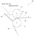
도 1은 제1 실시형태에 관한 수지 조성물 용액의 도포 방법을 설명하기 위한 측면 단면도이다.
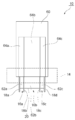
도 2는 도 1의 평면도이다.
도 3은 도 2에 도시한 사이드 플레이트(18b) 근방의 부분 확대 평면도이다.
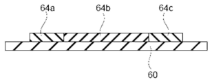
도 4는 각 도포막이 측면에서만 접속하는 경우를 도시하는 단면도이다.
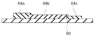
도 5는 도포막(64a) 및 도포막(64c)이, 도포막(64b) 상에 약간 중복되는 경우를 도시하는 단면도이다.
도 6은 도포막(64b)이, 도포막(64a) 및 도포막(64c) 상에 약간 중복되는 경우를 도시하는 단면도이다.
도 7은 제2 실시형태에 관한 수지 조성물 용액의 도포 방법을 설명하기 위한 측면 단면도이다.
도 8은 도 7의 평면도이다.
도 9는 제3 실시형태에 관한 수지 조성물 용액의 도포 방법을 설명하기 위한 측면 단면도이다.
도 10은 도 9의 평면도이다.
도 11은 도포막(64a)의 단부가 약간 도포막(64b) 상에 중복되고, 도포막(64b)의 단부가 약간 도포막(64c) 상에 중복되는 경우를 도시하는 단면도이다.
도 12는 제4 실시형태에 관한 수지 조성물 용액의 도포 방법을 설명하기 위한 측면 단면도이다.
도 13은 도 12의 평면도이다. 1 is a side sectional view for explaining a method of applying a resin composition solution according to a first embodiment.
FIG. 2 is a plan view of FIG. 1 .
Fig. 3 is a partially enlarged plan view of the vicinity of the
Fig. 4 is a cross-sectional view showing a case where each coating film is connected only from the side surface.
5 is a cross-sectional view showing a case where the
6 is a cross-sectional view showing a case where the
7 is a side cross-sectional view for explaining a method of applying a resin composition solution according to a second embodiment.
8 is a plan view of FIG. 7 .
9 is a side sectional view for explaining a method of applying a resin composition solution according to a third embodiment.
10 is a plan view of FIG. 9 .
Fig. 11 is a sectional view showing a case where the end of the
12 is a side sectional view for explaining a method of applying a resin composition solution according to a fourth embodiment.
Fig. 13 is a plan view of Fig. 12;
이하, 본 발명의 실시형태에 관해 설명한다. EMBODIMENT OF THE INVENTION Hereinafter, embodiment of this invention is described.
[수지 필름의 제조 방법][Method for manufacturing resin film]
본 실시형태에 관한 수지 필름의 제조 방법은, The manufacturing method of the resin film according to this embodiment,
지지체의 중앙부에 제1 수지 조성물 용액을 도포하는 공정 A, Step A of applying the first resin composition solution to the central portion of the support,
상기 중앙부에 인접하는 양쪽 단부에 무기 미립자를 함유하는 제2 수지 조성물 용액을 도포하는 공정 B, Step B of applying a second resin composition solution containing inorganic fine particles to both ends adjacent to the central portion;
상기 제1 수지 조성물 용액과 상기 제2 수지 조성물 용액을 건조시켜, 절단전 필름 적층체를 얻는 공정 C, Step C of drying the first resin composition solution and the second resin composition solution to obtain a film laminate before cutting;
상기 절단전 필름 적층체를 상기 지지체로부터 박리하여, 절단전 필름을 얻는 공정 D, Step D of peeling the film laminate before cutting from the support to obtain a film before cutting;
상기 공정 D의 후, 상기 절단전 필름의 양쪽 단부를 텐터식 반송 장치에 의해 파지하는 공정 E, Step E of gripping both ends of the pre-cut film with a tenter-type conveying device after the step D;
상기 절단전 필름의 양쪽 단부를 파지한 상태로, 상기 절단전 필름을 반송하는 공정 F, 및, Step F of conveying the film before cutting in a state where both ends of the film before cutting are held, and
상기 공정 F의 후, 상기 절단전 필름으로부터, 상기 제2 수지 조성물 용액으로 형성된 부분의 일부 또는 전부를 제거하는 공정 G를 가지며, After the step F, a step G of removing part or all of the portion formed from the second resin composition solution from the pre-cut film,
상기 양쪽 단부의 무기 미립자의 함유량이 상기 중앙부의 무기 미립자의 함유량보다 많다. The content of the inorganic fine particles at both ends is greater than the content of the inorganic fine particles at the central portion.
<공정 A, 공정 B> <Process A, Process B>
본 실시형태에 관한 수지 필름의 제조 방법에 있어서는, 우선, 지지체의 중앙부에 제1 수지 조성물 용액을 도포한다(공정 A). 또한, 상기 중앙부에 인접하는 양쪽 단부에 무기 미립자를 함유하는 제2 수지 조성물 용액을 도포한다(공정 B). 상기 공정 A와 상기 공정 B는 동시에 행해도 좋고, 상기 공정 A를 행한 후에 상기 공정 B를 행해도 좋고, 상기 공정 B를 행한 후에 상기 공정 A를 행해도 좋다. 상기 제2 수지 조성물 용액은 상기 제1 수지 조성물 용액의 양쪽 단부에 접촉해 있을 필요가 있다. In the manufacturing method of the resin film concerning this embodiment, first, the 1st resin composition solution is apply|coated to the central part of a support body (process A). Further, a second resin composition solution containing inorganic fine particles is applied to both ends adjacent to the central portion (Step B). The said process A and the said process B may be performed simultaneously, the said process B may be performed after performing the said process A, and the said process A may be performed after performing the said process B. The second resin composition solution needs to be in contact with both ends of the first resin composition solution.
상기 지지체로는, 특별히 한정되지 않지만, 제1 수지 조성물 용액 및 제2 수지 조성물 용액의 용매에 대하여 내성을 갖는 것이 바람직하고, 예컨대, PET(폴리에틸렌테레프탈레이트)와 같은 수지제의 필름이나, 금속 드럼, 엔드리스 스틸 벨트 등을 들 수 있다. The support is not particularly limited, but is preferably one having resistance to the solvents of the first resin composition solution and the second resin composition solution, and examples thereof include a resin film such as PET (polyethylene terephthalate) or a metal drum. , endless steel belts, and the like.
상기 공정 A 및 상기 공정 B의 도포 방법은, 특별히 한정되지 않고, 예컨대, 콤마코트법, T 다이코트법, 스핀코트법, 스프레이코트법, 바코트법, 나이프코트법, 디프법 등을 들 수 있다. 이들 중에서 2종의 방법을 조합해도 좋다. 콤마코트법, T 다이코트법, 혹은 이들의 조합이면 생산성의 관점에서 바람직하다. The coating method of the step A and the step B is not particularly limited, and examples thereof include a comma coat method, a T-die coat method, a spin coat method, a spray coat method, a bar coat method, a knife coat method, and a dip method. there is. You may combine 2 types of methods among these. A comma coat method, a T die coat method, or a combination thereof is preferred from the viewpoint of productivity.
이하, 공정 A 및 공정 B의 구체예에 관해 설명한다. Hereinafter, the specific example of process A and process B is demonstrated.
[제1 실시형태][First Embodiment]
도 1은, 제1 실시형태에 관한 수지 조성물 용액의 도포 방법을 설명하기 위한 측면 단면도이며, 도 2는, 그 평면도이다. 1 is a side cross-sectional view for explaining a method of applying a resin composition solution according to a first embodiment, and FIG. 2 is a plan view thereof.
도 1, 도 2에 도시하는 바와 같이, 도포 장치(10)는, 백업 롤(12)과, 콤마 롤(14)과, 3개의 도포액 저류부(16)(16a, 16b, 16c)를 갖는다. As shown in FIGS. 1 and 2 , the
도포액 저류부(16)(16a, 16b, 16c)는, 도포액 저류부(16)를 분획하기 위한 4개의 사이드 플레이트(18)(18a, 18b, 18c, 18d)와, 백플레이트(20)를 갖는다. 도포액 저류부(16)(16a, 16b, 16c)는, 백플레이트(20)와 사이드 플레이트(18)로 둘러싸인 영역에 도포액(62)을 저류하는 것이 가능하다. The coating liquid reservoir 16 (16a, 16b, 16c) includes four side plates 18 (18a, 18b, 18c, 18d) for dividing the
3개의 도포액 저류부(16)(16a, 16b, 16c) 중 양단측에 위치하는 도포액 저류부(16a, 16c)에는, 제2 수지 조성물 용액(62a, 62c)이 저류되고, 중앙에 위치하는 도포액 저류부(16b)에는, 제1 수지 조성물 용액(62b)이 저류된다. Among the three coating liquid reservoirs 16 (16a, 16b, 16c), the second
백업 롤(12)은, 회전하는 것에 의해 지지체(60)를 연속적으로 반송한다. 백업 롤(12)에 의해 반송되는 지지체(60)는, 백업 롤(12)과 콤마 롤(14) 사이에 형성된 간극(22)을 통과한다. 지지체(60)가 간극(22)을 통과할 때, 도포액 저류부(16)로부터 지지체(60) 상에 도포액(62)(제2 수지 조성물 용액(62a, 62c), 제1 수지 조성물 용액(62b))이 공급되고, 도포막(64)(64a, 64b, 64c)이 형성된다. 구체적으로는, 간극(22)으로부터 지지체(60)의 두께를 뺀 두께에 상당하는 도포막(64)이 형성된다. The
도포막(64)의 두께는, 백업 롤(12)과 콤마 롤(14) 사이의 간극(22) 등에 의해 컨트롤할 수 있다. The thickness of the
도 3은, 도 2에 도시한 사이드 플레이트(18b) 근방의 부분 확대 평면도이다. FIG. 3 is a partially enlarged plan view of the vicinity of the
각 도포액(62)(제2 수지 조성물 용액(62a, 62c), 제1 수지 조성물 용액(62b))은, 지지체(60) 상에 도포된 후 폭방향으로 퍼진다. 구체적으로는, 도 3에 도시하는 바와 같이, 사이드 플레이트(18b) 근방에 도포된 제2 수지 조성물 용액(62a)은, 폭방향 내측(도 2, 도 3에서는 우측)으로 퍼진다. 한편, 사이드 플레이트(18b) 근방에 도포된 제1 수지 조성물 용액(62b)은, 폭방향 외측(도 2, 도 3에서는 좌측)으로 퍼진다. 그리고, 유동 방향(도 2, 도 3에서는 상측)의 사이드 플레이트(18b)가 없어진 개소에서 제2 수지 조성물 용액(62a)(도포막(64a))과 제1 수지 조성물 용액(62b)(도포막(64b))이 접속된다. Each coating liquid 62 (second
마찬가지로, 사이드 플레이트(18c) 근방에 도포된 제1 수지 조성물 용액(62b)은, 폭방향 외측(도 2에서는 우측)으로 퍼진다. 한편, 사이드 플레이트(18c) 근방에 도포된 제2 수지 조성물 용액(62c)은, 폭방향 내측(도 2에서는 좌측)으로 퍼진다. 그리고, 유동 방향의 사이드 플레이트(18c)가 없어진 개소에서 제1 수지 조성물 용액(62b)(도포막(64b))과 제2 수지 조성물 용액(62c)(도포막(64c))이 접속된다. Similarly, the first
이상에 의해, 도포막(64a)과 도포막(64b)이 접속되고, 도포막(64b)과 도포막(64c)이 접속된다. 상기 접속은, 각 도포막(64)을 구성하는 각 수지 조성물 용액끼리 상용(相溶)하는 것에 의해 접속되는 경우나, 각 도포막(64)의 계면에서의 접착력에 의해 접속되는 경우 등을 들 수 있다. By the above, the
각 도포막(64)의 접속 양태로는, 특별히 한정되지 않지만, 각 도포막이 측면에서만 접속하는 경우(도 4 참조), 어느 한쪽의 도포막이 다른쪽의 도포막 상에 약간 중복되는 경우(도 5, 도 6 참조)를 들 수 있다. 보다 바람직한 접속 양태로는, 도 4 또는 도 5이며, 특히 바람직한 접속 양태로는 도 5이다. The connection mode of each
도 4는, 양쪽 단부의 막두께와 중앙부의 막두께가 거의 동일한 크기이며, 각 도포막이 측면에서만 접속하는 경우를 도시하는 단면도이다. Fig. 4 is a cross-sectional view showing a case in which the film thicknesses of both ends and the film thickness of the central portion are substantially the same, and the coating films are connected only from the side surfaces.
도 4에 도시하는 예에서는, 도포막(64a)과 도포막(64b)이 측면에서만 접속되어 있다. 또한, 도포막(64b)과 도포막(64c)이 측면에서만 접속되어 있다. 도포 직후는 측면에서만 접속되어 있지만, 이후에 계속되는 공정 C의 직전까지 제2 수지 조성물 용액(62a)(도포막(64a))과 제1 수지 조성물 용액(62b)(도포막(64b)), 혹은 제1 수지 조성물 용액(62b)(도포막(64b))과 제2 수지 조성물 용액(62c)(도포막(64c))이 혼합되는 것에 의해 조성 경사 영역을 만든다. 상기 조성 경사 영역의 폭은, 조성 경사 영역이 아닌 부분의 도포막(64b)의 두께의 10∼2500배의 범위인 것이 바람직하다. 보다 바람직하게는 100∼1000배이며, 더욱 바람직하게는 250∼500배이다. 예컨대, 도포막(64b)의 두께가 20 μm인 경우, 상기 조성 경사 영역의 폭은, 0.2 mm(도포막(64b)의 두께의 10배)∼5 cm(도포막(64b)의 두께의 2500배)가 바람직하다. 이 범위이면 제조중에 조성 경사 영역으로부터의 파단이 발생하기 어려워진다. In the example shown in FIG. 4, the
도 5는, 양쪽 단부의 막두께가 중앙부의 막두께보다 크고, 도포막(64a) 및 도포막(64c)이, 도포막(64b) 상에 약간 중복되는 경우를 도시하는 단면도이다. 5 is a cross-sectional view showing a case in which the film thickness at both ends is larger than the film thickness at the central portion, and the
도 5에 도시하는 예에서는, 도포막(64a)의 단부가 약간 도포막(64b) 상에 중복하고 있다. 또한, 도포막(64c)의 단부가 약간 도포막(64b) 상에 중복되어 있다. 중복 부분은 제2 수지 조성물 용액(62a)(도포막(64a))과 제1 수지 조성물 용액(62b)(도포막(64b)), 혹은 제1 수지 조성물 용액(62b)(도포막(64b))과 제2 수지 조성물 용액(62c)(도포막(64c))이 혼합되는 것에 의해 조성 경사 영역을 만든다. 상기 조성 경사 영역의 폭은, 조성 경사 영역이 아닌 부분의 도포막(64b)의 두께의 10∼2500배의 범위인 것이 바람직하다. 보다 바람직하게는 100∼1000배이며, 더욱 바람직하게는 250∼500배이다. 예컨대, 도포막(64b)의 두께가 20 μm인 경우, 상기 조성 경사 영역의 폭은, 0.2 mm(도포막(64b)의 두께의 10배)∼5 cm(도포막(64b)의 두께의 2500배)가 바람직하다. 이 범위이면 제조중에 조성 경사 영역에서의 파단이 발생하기 어려워진다. 또한, 수지 필름을 롤형으로 권취할 때에 중앙부의 막끼리 마찰되지 않고, 주름이나 이완 등이 생기기 어려워진다. In the example shown in FIG. 5, the edge part of the
도 6은, 양쪽 단부의 막두께가 중앙부의 막두께보다 작고, 도포막(64b)이, 도포막(64a) 및 도포막(64c) 상에 약간 중복되는 경우를 도시하는 단면도이다. Fig. 6 is a cross-sectional view showing a case where the film thickness at both ends is smaller than the film thickness at the central portion and the
도 6에 도시하는 예에서는, 도포막(64b)의 단부(도 6에서는 좌측의 단부)가 약간 도포막(64a) 상에 중복되어 있다. 또한, 도포막(64b)의 단부(도 6에서는 우측의 단부)가 약간 도포막(64c) 상에 중복되어 있다. 중복 부분의 폭의 일례로는, 도 5의 경우와 마찬가지로, 조성 경사 영역이 아닌 부분의 도포막(64b)의 10∼2500배의 범위인 것이 바람직하다. 보다 바람직하게는 100∼1000배이며, 더욱 바람직하게는 250∼500배이다. 이 범위이면 제조중에 조성 경사 영역에서의 파단이 발생하기 어려워진다. In the example shown in FIG. 6 , the end (left end in FIG. 6 ) of the
상기 접속 양태는, 예컨대 간극(22)에 의해 결정할 수 있다. 제2 수지 조성물 용액(62a, 62c)이 통과하는 간극(22)과, 제1 수지 조성물 용액(62b)이 통과하는 간극(22)을 동일하게 하면, 도 4에 도시한 양태의 접속 양태가 되기 쉽다. 제2 수지 조성물 용액(62a, 62c)이 통과하는 간극(22)을, 제1 수지 조성물 용액(62b)이 통과하는 간극(22)보다 약간 넓게 하면, 도 5에 도시한 양태의 접속 양태가 되기 쉽다. 제1 수지 조성물 용액(62b)이 통과하는 간극(22)을, 제2 수지 조성물 용액(62a, 62c)이 통과하는 간극(22)보다 약간 넓게 하면, 도 6에 도시한 양태의 접속 양태가 되기 쉽다. 한편, 상기 접속 양태는, 간극(22)뿐만 아니라, 제1 수지 조성물 용액(62b), 제2 수지 조성물 용액(62a, 62c)의 점도나, 사이드 플레이트(18)의 폭에 의해서도 컨트롤할 수 있다. The connection aspect can be determined by the
제1 실시형태에서는, 상기에서 설명한 도포 장치(10)에 의해, 공정 A와 공정 B를 동시에 행한다. In 1st Embodiment, process A and process B are performed simultaneously with the
이상, 제1 실시형태에 관한 공정 A 및 공정 B에 관해 설명했다. In the above, process A and process B concerning 1st Embodiment were demonstrated.
[제2 실시형태][Second Embodiment]
도 7은, 제2 실시형태에 관한 수지 조성물 용액의 도포 방법을 설명하기 위한 측면 단면도이며, 도 8은, 그 평면도이다. 한편, 제2 실시형태의 도포 장치(30)에 있어서 제1 실시형태의 도포 장치(10)와 공통된 구성에 관해서는 동일한 부호를 붙이고, 설명을 생략하거나 간단히 하는 것으로 한다. Fig. 7 is a side sectional view for explaining a method of applying a resin composition solution according to a second embodiment, and Fig. 8 is a plan view thereof. On the other hand, in the
도 7, 도 8에 도시하는 바와 같이, 도포 장치(30)는, 백업 롤(12)과, 콤마 롤(14)과, 폭방향의 양측에 2개의 도포액 저류부(16)(16a, 16c)를 갖는다. 도포액 저류부(16)(16a, 16c)는, 백플레이트(20)와 사이드 플레이트(18)로 둘러싸인 영역에 도포액(62)을 저류하는 것이 가능하다. 7 and 8, the
2개의 도포액 저류부(16)(16a, 16c)에는 제2 수지 조성물 용액(62a, 62c)이 저류된다. 한편, 제1 실시형태와 달리, 제2 실시형태에 관한 도포 장치(30)에 있어서는, 도포액 저류부(16)에 제1 수지 조성물 용액을 저류하지 않는다. The second
백업 롤(12)은, 회전하는 것에 의해 지지체(60)를 연속적으로 반송한다. 백업 롤(12)에 의해 반송되는 지지체(60)는, 백업 롤(12)과 콤마 롤(14) 사이에 형성된 간극(22)을 통과한다. 지지체(60)가 간극(22)을 통과할 때, 도포액 저류부(16)로부터 지지체(60) 상에 제2 수지 조성물 용액(62a, 62c)이 공급되고, 도포막(64a, 64c)이 형성된다. The
도포 장치(30)는, T 다이코터(32)를 더 구비한다. T 다이코터(32)는, 백업 롤(12), 콤마 롤(14)보다 후단에 설치되어 있다. T 다이코터(32)는, 지지체(60)의 중앙부 상측에 토출구가 위치하도록 설치되어 있다. The
도포막(64a, 64c)이 형성된 후의 지지체(60)가 반송되어 오면, T 다이코터(32)는, 지지체(60)의 중앙부에 제1 수지 조성물 용액(62b)을 도포한다. When the
제2 실시형태에서는, 상기에서 설명한 도포 장치(30)에 의해, 우선 공정 B를 먼저 행한 후, 공정 A를 행한다. 제2 실시형태의 경우, 각 도포막(64)의 접속 양태는, 도 6에 도시한 접속 양태가 되기 쉽지만 이것에 한정되지 않는다. 한편, 제2 실시형태의 변형예로서, 지지체의 중앙부에 먼저 콤마코터로 제1 수지 조성물 용액을 도포하고, 그 후, 양쪽 단부에 T 다이코터로 제2 수지 조성물 용액을 도포하는 것으로 해도 좋다. In 2nd Embodiment, after performing process B first by the
이상, 제2 실시형태에 관한 공정 A 및 공정 B에 관해 설명했다. In the above, process A and process B concerning 2nd Embodiment were demonstrated.
[제3 실시형태][Third Embodiment]
도 9는, 제3 실시형태에 관한 수지 조성물 용액의 도포 방법을 설명하기 위한 측면 단면도이며, 도 10은, 그 평면도이다. 한편, 제3 실시형태의 도포 장치(40)에 있어서 제2 실시형태의 도포 장치(30)와 공통된 구성에 관해서는 동일한 부호를 붙이고, 설명을 생략하거나 간단히 하는 것으로 한다. Fig. 9 is a side cross-sectional view for explaining a method of applying a resin composition solution according to a third embodiment, and Fig. 10 is a plan view thereof. In addition, in the
도포 장치(40)는, T 다이코터(42a), T 다이코터(42b), T 다이코터(42c)를 구비한다. T 다이코터(42a), T 다이코터(42c)는, T 다이코터(42b)보다 전단에 설치되어 있다. The
T 다이코터(42a), T 다이코터(42c)는, 각각, 지지체(60)의 단부 상측에 토출구가 위치하도록 설치되어 있다. 도 10에서는, T 다이코터(42a)는, 지지체(60)의 좌측 단부 상측에 토출구가 위치하도록 설치되고, T 다이코터(42c)는, 지지체(60)의 우측 단부 상측에 토출구가 위치하도록 설치되어 있다. The T die
T 다이코터(42b)는, 지지체(60)의 중앙부 상측에 토출구가 위치하도록 설치되어 있다. The T die
도포막(64a, 64c)이 형성된 후의 지지체(60)가 반송되어 오면, T 다이코터(42b)는, 지지체(60)의 중앙부에 제1 수지 조성물 용액(62b)을 도포한다. When the
제3 실시형태의 경우, 각 도포막(64)의 접합 양태는, 도 5에 도시한 접합 양태가 되기 쉽지만 이것에 한정되지 않는다. 또한, 제3 실시형태의 변형예로서, 제2 수지 조성물을 T 다이코터로 양쪽 단부에 도포하고, 그 후에 제1 수지 조성물을 T 다이코터로 중앙부에 도포하는 것으로 해도 좋다. 이 경우는 각 도포막(64)의 접합 양태는, 도 6에 도시한 접합 양태가 되기 쉽지만 이것에 한정되지 않는다. In the case of 3rd Embodiment, although the bonding aspect of each
또한, 별도의 변형예로서, 제2 수지 조성물을 T 다이코터로 한쪽의 단부에 도포하고, 그 후에 제1 수지 조성물을 T 다이코터로 중앙부에 도포하고, 계속해서 다른 한쪽의 단부에 제2 수지 조성물을 T 다이코터로 한쪽의 단부에 도포하는 것도 가능하다. 이 경우는 각 도포막(64)의 접합 양태는, 도 11에 도시한 접합 양태가 되기 쉽지만 이것에 한정되지 않는다. In addition, as another modification, the second resin composition is applied to one end portion with a T die coater, and then the first resin composition is applied to the central portion with a T die coater, and then the second resin composition is applied to the other end portion with a T die coater. It is also possible to apply the composition to one end with a T die coater. In this case, although the bonding aspect of each
도 11에 도시하는 예에서는, 도포막(64a)의 단부가 약간 도포막(64b) 상에 중복되어 있다. 또한, 도포막(64b)의 단부(도 11에서는 우측의 단부)가 약간 도포막(64c) 상에 중복되어 있다. In the example shown in FIG. 11, the edge part of the
제3 실시형태 및 그 변형예에 나타내는 바와 같이, 공정 A 및 공정 B는, 복수의 T 다이코터를 종렬적으로 배치하고, 제1 수지 조성물과 제2 수지 조성물을 차례대로 도포하는 형태이어도 좋다. As shown in 3rd Embodiment and its modified example, the process A and the process B may be a form which arrange|positions some T die coater in a row, and applies the 1st resin composition and the 2nd resin composition in sequence.
[제4 실시형태][Fourth Embodiment]
도 12는, 제4 실시형태에 관한 수지 조성물 용액의 도포 방법을 설명하기 위한 측면 단면도이며, 도 13은, 그 평면도이다. 한편, 제4 실시형태의 도포 장치(50)에 있어서 제3 실시형태의 도포 장치(40)와 공통된 구성에 관해서는 동일한 부호를 붙이고, 설명을 생략하거나 간단히 하는 것으로 한다. Fig. 12 is a side sectional view for explaining a method of applying a resin composition solution according to a fourth embodiment, and Fig. 13 is a plan view thereof. On the other hand, in the
도포 장치(50)는, 폭방향으로 3개로 분할된 토출구를 갖는 T 다이코터(52)를 구비한다. T 다이코터(52)는, 지지체(60)의 중앙부에 제1 수지 조성물을 도포하는 동시에 양쪽 단부에 제2 수지 조성물을 도포한다. The
도 12, 도 13에 도시하는 바와 같이, 제4 실시형태에서의 공정 A 및 공정 B는, 제1 수지 조성물과 제2 수지 조성물을 동시 도포하는 형태이다. 제4 실시형태의 경우, 각 도포막(64)의 접합 양태는, 도 4에 도시한 접합 양태가 되기 쉽지만 이것에 한정되지 않는다. As shown in FIG. 12 and FIG. 13, the process A and the process B in 4th Embodiment are the form which applies the 1st resin composition and the 2nd resin composition simultaneously. In the case of 4th Embodiment, although the bonding aspect of each
<공정 C> <Process C>
상기 공정 A 및 상기 공정 B의 후, 상기 제1 수지 조성물 용액과 상기 제2 수지 조성물 용액을 건조시켜, 절단전 필름 적층체를 얻는다(공정 C). 건조 조건으로는, 용매를 충분히 휘발시킬 수 있는 범위 내에서 적절하게 설정할 수 있고, 일례로서, 건조 온도 60℃∼140℃의 범위, 건조 시간 1분∼60분의 범위 내로 할 수 있다. 상기 건조 조건은, 특히, 디메틸아세트아미드를 용매로서 사용하는 경우, 그 비점이 165℃인 점에서 적합하다. After the said process A and the said process B, the said 1st resin composition solution and the said 2nd resin composition solution are dried, and the film laminated body before cutting is obtained (process C). Drying conditions can be appropriately set within a range in which the solvent can be sufficiently volatilized, and as an example, a drying temperature in the range of 60°C to 140°C and a drying time in the range of 1 minute to 60 minutes. The above drying conditions are particularly suitable in that the boiling point is 165°C when dimethylacetamide is used as the solvent.
공정 C의 후, 공정 D의 전에, 상기 절단전 필름 적층체를 상기 지지체마다 롤형으로 권취하는 공정(공정 C-1)을 행해도 좋다. 이 경우, 공정 D의 전에, 다시 상기 절단전 필름을 풀어내면 된다. 또한, 본 발명에서는, 양쪽 단부의 무기 미립자의 함유량이 중앙부의 무기 미립자의 함유량보다 많다. 그 때문에, 상기 도 4 또는 도 5의 구성이라면, 양쪽 단부의 슬라이딩성(마찰계수)이 중앙부의 슬라이딩성보다 커지기 때문에, 중앙부의 주름이나 이완 등의 발생을 방지할 수 있다. After process C and before process D, you may perform the process of winding up the said pre-cut film layered product in roll shape for every said support body (process C-1). In this case, what is necessary is just to unwind the said pre-cutting film again before process D. Further, in the present invention, the content of the inorganic fine particles at both end portions is greater than the content of the inorganic fine particles at the central portion. Therefore, in the configuration of FIG. 4 or 5, since the sliding properties (friction coefficients) of both end portions are greater than that of the central portion, occurrence of wrinkles or slack in the central portion can be prevented.
<공정 D> <Process D>
상기 공정 C의 후, 상기 절단전 필름 적층체를 상기 지지체로부터 박리하여, 절단전 필름을 얻는다(공정 D). 상기 절단전 필름 적층체를 상기 지지체로부터 박리하는 방법으로는, 특별히 제한되지 않지만, 핀셋 등으로 끝으로부터 걷어 올리는 방법, 절단전 필름 적층체에 칼집을 내고, 칼집을 낸 부분의 한 변에 점착 테이프를 접착시킨 후에 그 테이프 부분으로부터 걷어 올리는 방법, 절단전 필름의 칼집을 낸 부분의 한 변을 진공 흡착한 후에 그 부분으로부터 걷어 올리는 방법 등을 채용할 수 있다. 걷어 올리는 방법으로는, 롤에 권취하면서 걷어 올리는 것이 바람직하다. After the said process C, the said film laminated body before cutting is peeled from the said support body, and the film before cutting is obtained (process D). The method of peeling the film laminate before cutting from the support is not particularly limited, but is not particularly limited, but is a method of lifting from the end with tweezers or the like, a cut is made in the film laminate before cutting, and an adhesive tape is placed on one side of the cut portion. After adhering, a method of rolling up from the tape portion, a method of vacuum adsorbing one side of the cut portion of the film before cutting, and then lifting from that portion can be employed. As a method of rolling up, it is preferable to roll up while winding into a roll.
상기 절단전 필름 적층체에 칼집을 내는 방법으로는, 날붙이 등의 절삭 기구에 의해 절단전 필름 적층체를 절단하는 방법이나, 레이저에 의해 절단전 필름 적층체를 절단하는 방법, 워터제트에 의해 절단전 필름 적층체를 절단하는 방법 등이 있지만, 특별히 한정되는 것은 아니다. 예컨대, 전술한 방법을 채용함에 있어서, 절삭 기구에 초음파를 중첩시키거나, 왕복 동작이나 상하 동작 등을 부가하여 절삭 성능을 향상시키는 등의 수법을 적절하게 채용할 수도 있다. As a method of making cuts in the film laminate before cutting, a method of cutting the film laminate before cutting by a cutting mechanism such as a blade, a method of cutting the film laminate before cutting by a laser, or cutting by a water jet Although there exists a method etc. which cut all the film laminates, it is not specifically limited. For example, in adopting the above-described method, a method such as superimposing ultrasonic waves on a cutting mechanism or adding a reciprocating motion or an up-and-down motion to improve cutting performance may be appropriately employed.
공정 D의 후, 공정 E의 전에, 상기 절단전 필름을 롤형으로 권취하는 공정(공정 D-1)을 행해도 좋다. 이 경우, 공정 E의 전에, 다시 상기 절단전 필름을 풀어내면 된다. 상기 절단전 필름을 권취할 때에는, 합지(블로킹 방지 필름)를 사이에 끼워 권취하는 것이 바람직하다. 이 때, 상기 도 4 또는 도 5의 구성이면, 양쪽 단부의 슬라이딩성(마찰계수)이 중앙부의 슬라이딩성보다 커지기 때문에, 중앙부의 주름이나 이완 등의 발생을 방지할 수 있다. You may perform the process of winding up the said pre-cut film in roll shape (process D-1) after process D and before process E. In this case, what is necessary is just to unwind the said pre-cutting film again before process E. When winding up the film before cutting, it is preferable to wind it with a paper (blocking prevention film) interposed therebetween. At this time, in the configuration of FIG. 4 or 5, since the sliding properties (friction coefficients) of both ends are greater than the sliding properties of the central portion, it is possible to prevent wrinkles or slack from occurring in the central portion.
상기 공정 C-1 및/또는 상기 D-1의 공정을 실시하면, 건조 공정(공정 C)의 후, 절단 공정(공정 G)을 실시할 때까지 일정한 기간을 두는 것이 가능해진다. If the process C-1 and/or the process D-1 is performed, it becomes possible to set a fixed period after the drying process (process C) until the cutting process (process G) is performed.
건조 공정(공정 C)의 후에 상기 절단 필름 적층체를 한번 권취하고, 일정 기간 그 상태로 유지하는 것에 의해, 필름의 두께 방향의 용제 분포를 균등화할 수 있다. 이 점에 관해 이하에 설명한다. After the drying process (process C), the solvent distribution in the thickness direction of the film can be equalized by winding up the cut film layered product once and maintaining it in that state for a certain period of time. This point is demonstrated below.
도 5, 도 6에 도시하는 바와 같이, 2개의 도포막이 약간 중복되는 경우, 지지체 상에서 건조시킨 직후의 필름 중의 용제 분포는, 지지체측의 도포막의 용제 잔존량이 표면측의 도포막의 용제 잔존량보다 많다. 이 상태로, 가열 공정(예컨대 후술하는 공정 F)을 행하면, 용제 휘발량에 차가 생기고, 이 부분(중복 부분)에서 파열되기 쉬워질 우려가 있다. As shown in Figs. 5 and 6, when the two coating films overlap slightly, the distribution of the solvent in the film immediately after drying on the support is greater than the residual amount of the solvent in the coating film on the support side than the coating film on the surface side. . If a heating step (for example, step F to be described later) is performed in this state, there is a risk that a difference in the volatilization amount of the solvent will occur, and this part (overlapping part) will easily burst.
따라서, 상기 공정 C-1 및/또는 상기 D-1을 실시하여, 중복 부분의 두께 방향의 용제 분포를 균등화하는 것에 의해, 2종의 도포막의 용제 잔존량이 비교적 균등해지고, 이 중복 부분에서 파열되기 어렵게 할 수 있다. Therefore, by equalizing the distribution of the solvent in the thickness direction of the overlapping portion by carrying out the above-mentioned step C-1 and/or the above-mentioned D-1, the residual amount of the solvent in the two kinds of coating films becomes relatively equal, and the overlapping portion is less likely to burst. It can be difficult.
상기 공정 C-1의 후 및/또는 상기 공정 D-1의 후, 롤 상태로 유지하는 기간으로는, 바람직하게는 30분 이상, 더욱 바람직하게는 3시간 이상이다. 롤 상태로 상기 기간 유지하면, 용제를 적합하게 두께 방향으로 확산시킬 수 있다. After the said step C-1 and/or after the said step D-1, as a period of holding in a roll state, it is preferably 30 minutes or more, more preferably 3 hours or more. If maintained for the above period in a roll state, the solvent can be suitably diffused in the thickness direction.
또한, 상기 공정 C-1 및/또는 상기 D-1을 실시하면, 공정 도중에 한번 상기 절단전 필름을 권취하게 되므로, 생산 장치를 컴팩트하게 할 수 있다. 즉, 모든 공정을 연속적으로 접속하는 경우, 상당히 긴 제조 라인이 되어, 공장 입지 등이 제한되는 경우가 있다. 한편, 제조 도중에 권취 공정을 실시하면, 제조 라인을 둘로 나눌 수 있고, 이분한 2개의 라인을 병렬로 배치하는 것이 가능해져, 비교적 컴팩트한 제조 장치로 할 수 있다. Moreover, since the said pre-cut film is wound up once in the middle of a process, when the said process C-1 and/or said D-1 is carried out, a production apparatus can be made compact. That is, when all processes are connected continuously, it becomes a very long manufacturing line, and there are cases where factory locations and the like are limited. On the other hand, if the winding step is performed in the middle of production, the production line can be divided into two, and the two divided lines can be arranged in parallel, resulting in a relatively compact manufacturing device.
또한, 제조 도중에 한번 권취함으로써, 공정중에서의 품질 체크가 가능해진다. In addition, by winding once during manufacturing, quality check during the process becomes possible.
<공정 E> <Process E>
상기 공정 D의 후, 상기 절단전 필름의 양쪽 단부를 텐터식 반송 장치에 의해 파지한다(공정 E). 구체적으로는, 텐터식 반송 장치로서 핀 텐터식 반송 장치를 이용하는 경우에는, 상기 절단전 필름의 양쪽 단부를 핀 텐터식 반송 장치의 복수의 핀에 찌르는 것에 의해 파지한다. 또한, 텐터식 반송 장치로서, 클립 텐터식 반송 장치를 이용하는 경우에는, 상기 절단전 필름의 양쪽 단부를, 클립 텐터식 반송 장치의 복수의 클립 사이에 끼우는 것에 의해 파지한다. 텐터식 반송 장치로는, 종래 공지된 것(예컨대, 일본특허 제4843996호 공보, 일본특허 제4821960호 공보에 개시된 텐터식 반송 장치 등)을 사용할 수 있다. After the step D, both ends of the pre-cut film are gripped by a tenter conveyor (step E). Specifically, when a pin tenter type conveying device is used as a tenter type conveying device, both ends of the pre-cut film are gripped by piercing a plurality of pins of the pin tenter type conveying device. Further, when a clip tenter type conveying device is used as the tenter type conveying device, both ends of the pre-cut film are held between a plurality of clips of the clip tenter type conveying device. As the tenter-type conveying device, conventionally known ones (for example, tenter-type conveying devices disclosed in Japanese Patent No. 4843996 and Japanese Patent No. 4821960) can be used.
<공정 F> <Process F>
상기 공정 E의 후, 상기 절단전 필름의 양쪽 단부를 파지한 상태로, 상기 절단전 필름을 반송한다(공정 F). 반송시에는 가열해도 좋다. 가열 온도는 특별히 한정되지 않지만, 상기 제1 수지 조성물 용액 및 상기 제2 수지 조성물 용액이 폴리이미드계 수지 조성물 용액인 경우, 예컨대 150℃∼500℃, 1분∼60분의 범위 내로 할 수 있다. After the step E, the film before cutting is conveyed in a state where both ends of the film before cutting are held (step F). You may heat at the time of conveyance. The heating temperature is not particularly limited, but when the first resin composition solution and the second resin composition solution are polyimide-based resin composition solutions, for example, it can be within the range of 150 ° C. to 500 ° C., 1 minute to 60 minutes.
한편, 공정 E, 공정 F에서는, 폭방향으로 절단전 필름을 연신해도 좋고, 연신하지 않아도 좋다. On the other hand, in process E and process F, the film before cutting may be stretched in the width direction, or may not be stretched.
상기 공정 F에서는, 통상, 반송시에 상기 절단전 필름이 폭방향으로 줄어든다. 그 때문에, 텐터식 반송 장치에 파지되어 있는 부분에 인장 장력이 가해지게 된다. 상기 절단전 필름은, 바람직하게는, 양쪽 단부의 막두께가 중앙부의 막두께보다 두껍기 때문에, 파지한 부분(양쪽 단부)에서의 상기 절단전 필름의 파열을 억제할 수 있다. 또한, 상기 절단전 필름은, 양쪽 단부(제2 수지 조성물 용액으로 형성된 부분)의 인열 강도를, 중앙부(제2 수지 조성물 용액으로 형성된 부분)의 인열 강도보다 커지도록 하면, 파지한 부분(양쪽 단부)에서의 상기 절단전 필름의 파열을 더욱 억제할 수도 있다. 특히, 텐터식 반송 장치로서, 핀 텐터식 반송 장치를 이용하는 경우에는, 핀 텐터식 반송 장치의 핀에 의한 파열이 보다 적합하게 억제된다. In the said process F, normally, the said film before cutting shrinks in the width direction at the time of conveyance. For this reason, a tensile force is applied to the portion held by the tenter-type conveying device. Since the film thickness of the film before cutting is preferably thicker at both end portions than at the central portion, tearing of the film before cutting at the gripped portion (both ends) can be suppressed. In addition, the film before cutting, when the tear strength of both ends (the part formed of the second resin composition solution) is greater than the tear strength of the central part (the part formed of the second resin composition solution), the gripped part (both ends) ), it is also possible to further suppress the rupture of the film before cutting. In particular, when a pin tenter type conveying device is used as the tenter type conveying device, bursting by the pins of the pin tenter type conveying device is suppressed more suitably.
<공정 G> <Process G>
상기 공정 F의 후, 상기 절단전 필름으로부터, 상기 제2 수지 조성물 용액으로 형성된 부분의 일부 또는 전부를 제거하여, 수지 필름을 얻는다(공정 G). 공정 G에서는, 적어도 상기 제2 수지 조성물 용액으로 형성된 부분의 일부 또는 전부를 제거하면 되며, 상기 제2 수지 조성물 용액으로 형성된 부분과 함께, 상기 제1 수지 조성물 용액으로 형성된 부분도 일부 제거되어도 좋다. 즉, 상기 수지 필름은, 「단부/중앙부/단부」의 구성으로부터 양쪽 단부의 일부 또는 전부를 제거하면 되는 것이며, 예컨대, 「일부 절제한 단부/중앙부/단부」, 「일부 절제한 단부/중앙부/일부 절제한 단부」, 「단부/중앙부」, 「일부 절제한 단부/중앙부」, 「중앙부」, 또는, 「일부 절제한 중앙부」 중 어느 것이라도 상관없다. After the said process F, part or all of the part formed from the said 2nd resin composition solution is removed from the said film before cutting, and a resin film is obtained (process G). In step G, at least a part or all of the portion formed of the second resin composition solution may be removed, and a portion formed of the first resin composition solution may also be partially removed together with the portion formed of the second resin composition solution. In other words, the resin film is obtained by removing part or all of both ends from the structure of "end/center/end", for example, "partially cut end/center/end", "partially cut end/center/end" Any of "partially cut end part", "end/central part", "partially cut end/center part", "central part", or "partially cut off central part" may be used.
상기 절단전 필름에서의 중앙부의 막두께(두께)로는, 특별히 한정되지 않지만, 5 μm∼125 μm가 바람직하고, 7.5 μm∼75 μm가 보다 바람직하고, 12.5 μm∼50 μm가 더욱 바람직하다. 또한, 양쪽 단부의 막두께(두께)로는, 특별히 한정되지 않지만, 10 μm∼200 μm가 바람직하고, 15 μm∼180 μm가 보다 바람직하고, 20 μm∼150 μm가 더욱 바람직하다. 각 양쪽 단부의 막두께는 동일해도 좋고 상이해도 좋지만, 동일한 것이 바람직하다. 상기 각 양쪽 단부의 막두께는 중앙부의 막두께보다 큰 것이 바람직하다. 각 양쪽 단부의 막두께와 중앙부의 막두께의 비율(양쪽 단부/중앙부)은, 1 초과인 것이 바람직하다. 중앙부의 주름이나 이완을 방지하기 쉬워지는 점에서, 보다 바람직하게는 1.25 이상이고, 더욱 바람직하게는 1.5 이상이다. 또한, 양쪽 단부와 중앙부의 건조 상태에 차이가 나지 않도록 하기 위해, 20 이하인 것이 바람직하고, 보다 바람직하게는 10 이하이며, 더욱 바람직하게는 5 이하이다. 상기 절단전 필름에서의 막두께가 수지 필름의 막두께가 된다. The film thickness (thickness) of the central portion of the film before cutting is not particularly limited, but is preferably 5 μm to 125 μm, more preferably 7.5 μm to 75 μm, still more preferably 12.5 μm to 50 μm. Further, the film thickness (thickness) of both ends is not particularly limited, but is preferably 10 μm to 200 μm, more preferably 15 μm to 180 μm, still more preferably 20 μm to 150 μm. The film thickness of each both ends may be the same or different, but it is preferable that they are the same. It is preferable that the film thickness of each end part is larger than the film thickness of the central part. It is preferable that the ratio of the film thickness of each end part to the film thickness of the central part (both end parts/central part) exceeds 1. It is more preferably 1.25 or more, and even more preferably 1.5 or more from the viewpoint of making it easier to prevent wrinkles and slack in the central portion. Further, in order to prevent a difference in the dryness of both ends and the central portion, it is preferably 20 or less, more preferably 10 or less, still more preferably 5 or less. The film thickness of the film before cutting is the film thickness of the resin film.
상기 절단전 필름으로부터, 상기 제2 수지 조성물 용액으로 형성된 부분을 제거하는 방법으로는, 특별히 한정되지 않고, 종래 공지의 슬리터 등을 이용할 수 있다. 이 때, 절단부(절단면)가 발생한다. The method for removing the portion formed of the second resin composition solution from the film before cutting is not particularly limited, and a conventionally known slitter or the like can be used. At this time, a cut portion (cut surface) is generated.
이상, 본 실시형태에 관한 수지 필름의 제조 방법에 의하면, 본 발명에 의하면, 종래 공지의 권취 장치를 이용하여 투명성이 우수한 필름을 권취할 때에, 필름에 생기는 주름 등의 권취시의 문제점을 효과적으로 억제할 수 있게 된다. As described above, according to the manufacturing method of the resin film according to the present embodiment, according to the present invention, when winding a film excellent in transparency using a conventionally known winding device, problems at the time of winding such as wrinkles generated in the film are effectively suppressed. You can do it.
이하, 상기 제1 수지 조성물 용액 및 상기 제2 수지 조성물 용액(이하, 단순히 「수지 조성물 용액」이라고도 함)에 관해 설명한다. Hereinafter, the first resin composition solution and the second resin composition solution (hereinafter, simply referred to as "resin composition solution") will be described.
상기 제1 수지 조성물 용액 및 상기 제2 수지 조성물 용액은, 상기 절단전 필름 및 상기 수지 필름에 있어서, 상기 제2 수지 조성물 용액으로 형성된 부분의 무기 미립자의 함유량이, 상기 제1 수지 조성물 용액으로 형성된 부분의 무기 미립자의 함유량보다 커지는 구성이라면, 특별히 한정되지 않는다. In the first resin composition solution and the second resin composition solution, in the pre-cut film and the resin film, the content of the inorganic fine particles in the portion formed of the second resin composition solution formed of the first resin composition solution It is not particularly limited as long as it is a structure larger than the content of the inorganic fine particles in the portion.
상기 수지 조성물 용액으로는, 폴리이미드계 수지 조성물 용액, 폴리아미드계 수지 조성물 용액, 폴리아미드이미드계 수지 조성물 용액, 폴리에스테르계 수지 조성물 용액, 폴리올레핀계 수지 조성물 용액, 폴리스티렌계 수지 조성물 용액 등을 들 수 있다. 그 중에서도, 투명성, 내열성, 기계 강도가 양호하다는 점에서, 폴리이미드계 수지 조성물 용액이 바람직하다. Examples of the resin composition solution include a polyimide-based resin composition solution, a polyamide-based resin composition solution, a polyamide-imide-based resin composition solution, a polyester-based resin composition solution, a polyolefin-based resin composition solution, and a polystyrene-based resin composition solution. can Among them, a polyimide-based resin composition solution is preferable in terms of good transparency, heat resistance, and mechanical strength.
상기 폴리이미드계 수지 조성물 용액은, 폴리아미드산(폴리이미드 전구체) 용액이어도 좋고, 폴리이미드 용액이어도 좋다. 폴리아미드산 용액을 이용하는 경우, 공정 F에서 열처리하는 것에 의해, 탈수 폐환 반응을 행하게 하여 폴리이미드의 필름이 된다. 폴리이미드 용액을 이용하는 경우, 공정 C에서 용매를 휘발시키는 것에 의해, 폴리이미드의 필름이 된다. The polyimide-based resin composition solution may be a polyamic acid (polyimide precursor) solution or a polyimide solution. In the case of using a polyamic acid solution, by heat treatment in step F, a dehydration ring closure reaction is performed to form a polyimide film. When using a polyimide solution, it becomes a film of polyimide by volatilizing a solvent in process C.
본 발명에서의 폴리이미드 필름은, 주쇄에 이미드 결합을 갖는 고분자의 필름이며, 바람직하게는 폴리이미드 필름, 폴리아미드이미드 필름, 폴리아미드 필름이며, 보다 바람직하게는 폴리이미드 필름, 폴리아미드이미드 필름이며, 더욱 바람직하게는 폴리이미드 필름이다. The polyimide film in the present invention is a film of a polymer having an imide bond in the main chain, preferably a polyimide film, a polyamideimide film, or a polyamide film, more preferably a polyimide film or a polyamideimide film. and more preferably a polyimide film.
일반적으로, 폴리이미드 필름은, 용매 중에서 디아민류와 테트라카르복실산류를 반응시켜 얻어지는 폴리아미드산(폴리이미드 전구체) 용액을, 폴리이미드 필름 제작용 지지체에 도포, 건조하여 그린 필름(「전구체 필름」 또는 「폴리아미드산 필름」이라고도 함)으로 하고, 또한 폴리이미드 필름 제작용 지지체 상에서, 혹은 상기 지지체로부터 박리한 상태에서, 그린 필름을 고온 열처리하여 탈수 폐환 반응을 행하게 함으로써 얻어진다. 또한, 별도의 방법으로서, 용매 중에서 디아민류와 테트라카르복실산류와의 탈수 폐환 반응에 의해 얻어지는 폴리이미드 용액을 폴리이미드 필름 제작용 지지체에 도포, 건조하여 1∼50 질량%의 용매를 포함하는 폴리이미드 필름으로 하고, 또한 폴리이미드 필름 제작용 지지체 상에서, 혹은 상기 지지체로부터 박리한 상태에서, 1∼50 질량%의 용매를 포함하는 폴리이미드 필름을 고온 처리하여 건조시킴으로써 얻어진다. In general, a polyimide film is obtained by applying a polyamide acid (polyimide precursor) solution obtained by reacting diamines and tetracarboxylic acids in a solvent to a support for producing a polyimide film and drying it to form a green film ("precursor film"). Alternatively, it is also referred to as "polyamic acid film"), and is obtained by subjecting a green film to a high-temperature heat treatment to undergo a dehydration ring closure reaction on a support for producing a polyimide film or in a state peeled from the support. In addition, as a separate method, a polyimide solution obtained by a dehydration ring closure reaction of diamines and tetracarboxylic acids in a solvent is applied to a support for producing a polyimide film and dried to form a polyimide solution containing 1 to 50% by mass of a solvent. It is obtained by setting it as a mid film and further subjecting a polyimide film containing 1 to 50% by mass of a solvent to a high temperature and drying it on a support for polyimide film production or in a state peeled from the support.
또한, 일반적으로, 폴리아미드이미드 필름은, 용매 중에서 디이소시아네이트류와 트리카르본류를 반응시켜 얻어지는 폴리아미드이미드 용액을, 폴리아미드이미드 필름 제작용 지지체에 도포, 건조하여 1∼50 질량%의 용매를 포함하는 폴리아미드이미드 필름으로 하고, 또한 폴리아미드이미드 제작용 지지체 상에서, 혹은 상기 지지체로부터 박리한 상태에서, 1∼50 질량%의 용매를 포함하는 폴리아미드이미드 필름을 고온 처리하여 건조시킴으로써 얻어진다. In general, a polyamide-imide film is obtained by applying a polyamide-imide solution obtained by reacting diisocyanates and tricarbones in a solvent to a support for producing a polyamide-imide film and drying it to remove 1 to 50% by mass of the solvent. It is obtained by treating a polyamideimide film containing 1 to 50% by mass of a solvent at a high temperature and drying it as a containing polyamideimide film, on a support for producing polyamideimide, or in a state peeled from the support.
또한, 일반적으로, 폴리아미드 필름은, 용매 중에서 디아민류와 디카르복실산류를 반응시켜 얻어지는 폴리아미드 용액을 폴리아미드 필름 제작용 지지체에 도포, 건조하여 1∼50 질량%의 용매를 포함하는 폴리아미드 필름으로 하고, 또한 폴리아미드 제작용 지지체 상에서, 혹은 상기 지지체로부터 박리한 상태에서, 1∼50 질량%의 용매를 포함하는 폴리아미드 필름을 고온 처리하여 건조시킴으로써 얻어진다. Further, in general, a polyamide film is obtained by applying a polyamide solution obtained by reacting diamines and dicarboxylic acids in a solvent to a support for producing a polyamide film and drying the polyamide containing 1 to 50% by mass of a solvent. It is obtained by treating a polyamide film containing 1 to 50% by mass of a solvent at a high temperature and drying it as a film, on a support for producing polyamide, or in a state peeled from the support.
상기 테트라카르복실산류, 트리카르복실산류, 디카르복실산류로는, 폴리이미드 합성, 폴리아미드이미드 합성, 폴리아미드 합성에 통상 이용되는 방향족 테트라카르복실산류(그 산무수물을 포함), 지방족 테트라카르복실산류(그 산무수물을 포함), 지환식 테트라카르복실산류(그 산무수물을 포함), 방향족 트리카르복실산류(그 산무수물을 포함), 지방족 트리카르복실산류(그 산무수물을 포함), 지환식 트리카르복실산류(그 산무수물을 포함), 방향족 디카르본류, 지방족 디카르복실산류, 지환식 디카르복실산류 등을 이용할 수 있다. 그 중에서도, 방향족 테트라카르복실산무수물류, 지방족 테트라카르복실산무수물류가 바람직하고, 내열성의 관점에서는 방향족 테트라카르복실산무수물류가 보다 바람직하고, 광투과성의 관점에서는 지환식 테트라카르복실산류가 보다 바람직하다. 테트라카르복실산류가 산무수물인 경우, 분자 내에 무수물 구조는 1개이어도 좋고 2개이어도 좋지만, 바람직하게는 2개의 무수물 구조를 갖는 것(이무수물)이 좋다. 테트라카르복실산류, 트리카르복실산류, 디카르복실산류는 단독으로 이용해도 좋고, 2종 이상을 병용해도 좋다. Examples of the tetracarboxylic acids, tricarboxylic acids, and dicarboxylic acids include aromatic tetracarboxylic acids (including acid anhydrides thereof) commonly used in polyimide synthesis, polyamideimide synthesis, and polyamide synthesis, and aliphatic tetracarboxylic acids. boxylic acids (including their acid anhydrides), alicyclic tetracarboxylic acids (including their acid anhydrides), aromatic tricarboxylic acids (including their acid anhydrides), aliphatic tricarboxylic acids (including their acid anhydrides), Alicyclic tricarboxylic acids (including their acid anhydrides), aromatic dicarboxylic acids, aliphatic dicarboxylic acids, alicyclic dicarboxylic acids and the like can be used. Among them, aromatic tetracarboxylic acid anhydrides and aliphatic tetracarboxylic acid anhydrides are preferred, aromatic tetracarboxylic acid anhydrides are more preferred from the viewpoint of heat resistance, and alicyclic tetracarboxylic acids are preferred from the viewpoint of light transmittance. more preferable When the tetracarboxylic acid is an acid anhydride, it may have one or two anhydride structures in the molecule, but preferably has two anhydride structures (dianhydride). Tetracarboxylic acids, tricarboxylic acids, and dicarboxylic acids may be used alone or in combination of two or more.
본 발명에서의 무색 투명성이 높은 폴리이미드를 얻기 위한 방향족 테트라카르복실산류로는, 피로멜리트산, 4,4'-(2,2-헥사플루오로이소프로필리덴)디프탈산, 4,4'-옥시디프탈산, 3,4'-옥시디프탈산, 비스(1,3-디옥소-1,3-디히드로-2-벤조푸란-5-카르복실산)1,4-페닐렌, 비스(1,3-디옥소-1,3-디히드로-2-벤조푸란-5-일)벤젠-1,4-디카르복실레이트, 4,4'-[4,4'-(3-옥소-1,3-디히드로-2-벤조푸란-1,1-디일)비스(벤젠-1,4-디일옥시)]디벤젠-1,2-디카르복실산, 3,3',4,4'-벤조페논테트라카르복실산, 4,4'-[(3-옥소-1,3-디히드로-2-벤조푸란-1,1-디일)비스(톨루엔-2,5-디일옥시)]디벤젠-1,2-디카르복실산, 4,4'-[(3-옥소-1,3-디히드로-2-벤조푸란-1,1-디일)비스(1,4-크실렌-2,5-디일옥시)]디벤젠-1,2-디카르복실산, 4,4'-[4,4'-(3-옥소-1,3-디히드로-2-벤조푸란-1,1-디일)비스(4-이소프로필-톨루엔-2,5-디일옥시)]디벤젠-1,2-디카르복실산, 4,4'-[4,4'-(3-옥소-1,3-디히드로-2-벤조푸란-1,1-디일)비스(나프탈렌-1,4-디일옥시)]디벤젠-1,2-디카르복실산, 4,4'-[4,4'-(3H-2,1-벤즈옥사티올-1,1-디옥시드-3,3-디일)비스(벤젠-1,4-디일옥시)]디벤젠-1,2-디카르복실산, 4,4'-벤조페논테트라카르복실산, 4,4'-[(3H-2,1-벤즈옥사티올-1,1-디옥시드-3,3-디일)비스(톨루엔-2,5-디일옥시)]디벤젠-1,2-디카르복실산, 4,4'-[(3H-2,1-벤즈옥사티올-1,1-디옥시드-3,3-디일)비스(1,4-크실렌-2,5-디일옥시)]디벤젠-1,2-디카르복실산, 4,4'-[4,4'-(3H-2,1-벤즈옥사티올-1,1-디옥시드-3,3-디일)비스(4-이소프로필-톨루엔-2,5-디일옥시)]디벤젠-1,2-디카르복실산, 4,4'-[4,4'-(3H-2,1-벤즈옥사티올-1,1-디옥시드-3,3-디일)비스(나프탈렌-1,4-디일옥시)]디벤젠-1,2-디카르복실산, 3,3',4,4'-디페닐술폰테트라카르복실산, 3,3',4,4'-비페닐테트라카르복실산, 2,3,3',4'-비페닐테트라카르복실산, 2,2',3,3'-비페닐테트라카르복실산, 2,2'-디페녹시-4,4',5,5'-비페닐테트라카르복실산, 피로멜리트산, 4,4'-[스피로(크산텐-9,9'-플루오렌)-2,6-디일비스(옥시카르보닐)]디프탈산, 4,4'-[스피로(크산텐-9,9'-플루오렌)-3,6-디일비스(옥시카르보닐)]디프탈산 등의 테트라카르복실산 및 이들의 산무수물을 들 수 있다. 이들 중에서도, 2개의 산무수물 구조를 갖는 이무수물이 적합하며, 특히, 4,4'-(2,2-헥사플루오로이소프로필리덴)디프탈산이무수물, 4,4'-옥시디프탈산이무수물이 바람직하다. 또한, 방향족 테트라카르복실산류는 단독으로 이용해도 좋고, 2종 이상을 병용해도 좋다. 방향족 테트라카르복실산류는, 내열성을 중시하는 경우에는, 예컨대, 전체 테트라카르복실산류의 50 질량% 이상이 바람직하고, 보다 바람직하게는 60 질량% 이상, 더욱 바람직하게는 70 질량% 이상, 더욱 더 바람직하게는 80 질량% 이상이다. As aromatic tetracarboxylic acids for obtaining a colorless and highly transparent polyimide in the present invention, pyromellitic acid, 4,4'-(2,2-hexafluoroisopropylidene)diphthalic acid, 4,4'- Oxydiphthalic acid, 3,4'-oxydiphthalic acid, bis(1,3-dioxo-1,3-dihydro-2-benzofuran-5-carboxylic acid) 1,4-phenylene, bis(1 ,3-dioxo-1,3-dihydro-2-benzofuran-5-yl)benzene-1,4-dicarboxylate, 4,4'-[4,4'-(3-oxo-1 ,3-dihydro-2-benzofuran-1,1-diyl)bis(benzene-1,4-diyloxy)]dibenzene-1,2-dicarboxylic acid, 3,3',4,4 '-benzophenonetetracarboxylic acid, 4,4'-[(3-oxo-1,3-dihydro-2-benzofuran-1,1-diyl)bis(toluene-2,5-diyloxy) ]Dibenzene-1,2-dicarboxylic acid, 4,4'-[(3-oxo-1,3-dihydro-2-benzofuran-1,1-diyl)bis(1,4-xylene- 2,5-diyloxy)]dibenzene-1,2-dicarboxylic acid, 4,4'-[4,4'-(3-oxo-1,3-dihydro-2-benzofuran-1 ,1-diyl)bis(4-isopropyl-toluene-2,5-diyloxy)]dibenzene-1,2-dicarboxylic acid, 4,4'-[4,4'-(3-oxo -1,3-dihydro-2-benzofuran-1,1-diyl)bis(naphthalene-1,4-diyloxy)]dibenzene-1,2-dicarboxylic acid, 4,4'-[ 4,4'-(3H-2,1-benzoxathiol-1,1-dioxide-3,3-diyl)bis(benzene-1,4-diyloxy)]dibenzene-1,2-dica Riboxylic acid, 4,4'-benzophenonetetracarboxylic acid, 4,4'-[(3H-2,1-benzoxathiol-1,1-dioxide-3,3-diyl)bis(toluene- 2,5-diyloxy)]dibenzene-1,2-dicarboxylic acid, 4,4'-[(3H-2,1-benzoxathiol-1,1-dioxide-3,3-diyl )bis(1,4-xylene-2,5-diyloxy)]dibenzene-1,2-dicarboxylic acid, 4,4'-[4,4'-(3H-2,1-benzoxa) Thiol-1,1-dioxide-3,3-diyl)bis(4-isopropyl-toluene-2,5-diyloxy)]dibenzene-1,2-dicarboxylic acid, 4,4'- [4,4'-(3H-2,1-benzoxathiol-1,1-dioxide-3,3-diyl)bis(naphthalene-1,4-diyloxy)]dibenzene-1,2- Dicarboxylic acid, 3,3',4,4 '-diphenylsulfotetracarboxylic acid, 3,3',4,4'-biphenyltetracarboxylic acid, 2,3,3',4'-biphenyltetracarboxylic acid, 2,2',3 ,3'-biphenyltetracarboxylic acid, 2,2'-diphenoxy-4,4',5,5'-biphenyltetracarboxylic acid, pyromellitic acid, 4,4'-[spiro Santhene-9,9'-fluorene)-2,6-diylbis(oxycarbonyl)]diphthalic acid, 4,4'-[spiro(xanthene-9,9'-fluorene)-3,6- tetracarboxylic acids such as diylbis(oxycarbonyl)]diphthalic acid and acid anhydrides thereof. Among these, dianhydrides having two acid anhydride structures are suitable, particularly 4,4'-(2,2-hexafluoroisopropylidene)diphthalic dianhydride and 4,4'-oxydiphthalic dianhydride. this is preferable Moreover, aromatic tetracarboxylic acids may be used independently and may use 2 or more types together. Aromatic tetracarboxylic acids are preferably 50% by mass or more, more preferably 60% by mass or more, still more preferably 70% by mass or more, and even more preferably 50% by mass or more of all tetracarboxylic acids, when importance is placed on heat resistance. Preferably it is 80 mass % or more.
지환식 테트라카르복실산류로는, 1,2,3,4-시클로부탄테트라카르복실산, 1,2,3,4-시클로펜탄테트라카르복실산, 1,2,3,4-시클로헥산테트라카르복실산, 1,2,4,5-시클로헥산테트라카르복실산, 3,3',4,4'-비시클로헥실테트라카르복실산, 비시클로[2,2,1]헵탄-2,3,5,6-테트라카르복실산, 비시클로[2,2,2]옥탄-2,3,5,6-테트라카르복실산, 비시클로[2,2,2]옥토-7-엔-2,3,5,6-테트라카르복실산, 테트라히드로안트라센-2,3,6,7-테트라카르복실산, 테트라데카히드로-1,4:5,8:9,10-트리메타노안트라센-2,3,6,7-테트라카르복실산, 데카히드로나프탈렌-2,3,6,7-테트라카르복실산, 데카히드로-1,4:5,8-디메타노나프탈렌-2,3,6,7-테트라카르복실산, 데카히드로-1,4-에타노-5,8-메타노나프탈렌-2,3,6,7-테트라카르복실산, 노보난-2-스피로-α-시클로펜타논-α'-스피로-2''-노보난-5,5'',6,6''-테트라카르복실산(별칭 「노보난-2-스피로-2'-시클로펜타논-5'-스피로-2''-노보난-5,5'',6,6''-테트라카르복실산」), 메틸노보난-2-스피로-α-시클로펜타논-α'-스피로-2''-(메틸노보난)-5,5'',6,6''-테트라카르복실산, 노보난-2-스피로-α-시클로헥사논-α'-스피로-2''-노보난-5,5'',6,6''-테트라카르복실산(별칭 「노보난-2-스피로-2'-시클로헥사논-6'-스피로-2''-노보난-5,5'',6,6''-테트라카르복실산」), 메틸노보난-2-스피로-α-시클로헥사논-α'-스피로-2''-(메틸노보난)-5,5'',6,6''-테트라카르복실산, 노보난-2-스피로-α-시클로프로파논-α'-스피로-2''-노보난-5,5'',6,6''-테트라카르복실산, 노보난-2-스피로-α-시클로부타논-α'-스피로-2''-노보난-5,5'',6,6''-테트라카르복실산, 노보난-2-스피로-α-시클로헵타논-α'-스피로-2''-노보난-5,5'',6,6''-테트라카르복실산, 노보난-2-스피로-α-시클로옥타논-α'-스피로-2''-노보난-5,5'',6,6''-테트라카르복실산, 노보난-2-스피로-α-시클로노나논-α'-스피로-2''-노보난-5,5'',6,6''-테트라카르복실산, 노보난-2-스피로-α-시클로데카논-α'-스피로-2''-노보난-5,5'',6,6''-테트라카르복실산, 노보난-2-스피로-α-시클로운데카논-α'-스피로-2''-노보난-5,5'',6,6''-테트라카르복실산, 노보난-2-스피로-α-시클로도데카논-α'-스피로-2''-노보난-5,5'',6,6''-테트라카르복실산, 노보난-2-스피로-α-시클로트리데카논-α'-스피로-2''-노보난-5,5'',6,6''-테트라카르복실산, 노보난-2-스피로-α-시클로테트라데카논-α'-스피로-2''-노보난-5,5'',6,6''-테트라카르복실산, 노보난-2-스피로-α-시클로펜타데카논-α'-스피로-2''-노보난-5,5'',6,6''-테트라카르복실산, 노보난-2-스피로-α-(메틸시클로펜타논)-α'-스피로-2''-노보난-5,5'',6,6''-테트라카르복실산, 노보난-2-스피로-α-(메틸시클로헥사논)-α'-스피로-2''-노보난-5,5'',6,6''-테트라카르복실산 등의 테트라카르복실산 및 이들의 산무수물을 들 수 있다. 또한, 식 (1)의 구조로 표시되는 산무수물기 함유의 더블데커형 실세스퀴옥산 유도체 등도 들 수 있다. 이들 중에서도, 2개의 산무수물 구조를 갖는 이무수물이 적합하며, 특히, 1,2,3,4-시클로부탄테트라카르복실산이무수물, 1,2,3,4-시클로헥산테트라카르복실산이무수물, 1,2,4,5-시클로헥산테트라카르복실산이무수물이 바람직하고, 1,2,3,4-시클로부탄테트라카르복실산이무수물, 1,2,4,5-시클로헥산테트라카르복실산이무수물이 보다 바람직하고, 1,2,3,4-시클로부탄테트라카르복실산이무수물이 더욱 바람직하다. 또한, 이들은 단독으로 이용해도 좋고, 2종 이상을 병용해도 좋다. 지환식 테트라카르복실산류는, 투명성을 중시하는 경우에는, 예컨대, 전체 테트라카르복실산류의 50 질량% 이상이 바람직하고, 보다 바람직하게는 60 질량% 이상, 더욱 바람직하게는 70 질량% 이상, 더욱 더 바람직하게는 80 질량% 이상이다.As alicyclic tetracarboxylic acids, 1,2,3,4-cyclobutane tetracarboxylic acid, 1,2,3,4-cyclopentane tetracarboxylic acid, 1,2,3,4-cyclohexanetetra Carboxylic acid, 1,2,4,5-cyclohexanetetracarboxylic acid, 3,3',4,4'-bicyclohexyltetracarboxylic acid, bicyclo[2,2,1]heptane-2, 3,5,6-tetracarboxylic acid, bicyclo[2,2,2]octane-2,3,5,6-tetracarboxylic acid, bicyclo[2,2,2]octo-7-ene- 2,3,5,6-tetracarboxylic acid, tetrahydroanthracene-2,3,6,7-tetracarboxylic acid, tetradecahydro-1,4:5,8:9,10-trimethanoanthracene -2,3,6,7-tetracarboxylic acid, decahydronaphthalene-2,3,6,7-tetracarboxylic acid, decahydro-1,4:5,8-dimethanonaphthalene-2,3 ,6,7-tetracarboxylic acid, decahydro-1,4-ethano-5,8-methanonaphthalene-2,3,6,7-tetracarboxylic acid, norbonane-2-spiro-α- Cyclopentanone-α'-spiro-2''-norbonane-5,5'',6,6''-tetracarboxylic acid (aka "norbonane-2-spiro-2'-cyclopentanone-5 '-spiro-2''-norbonane-5,5'',6,6''-tetracarboxylic acid'), methylnorbornane-2-spiro-α-cyclopentanone-α'-spiro-2 ''-(methylnorbonane)-5,5'',6,6''-tetracarboxylic acid, norbonane-2-spiro-α-cyclohexanone-α'-spiro-2''-norbonane -5,5'',6,6''-tetracarboxylic acid (aka "norbonane-2-spiro-2'-cyclohexanone-6'-spiro-2''-norbonane-5,5' ',6,6''-tetracarboxylic acid'), methylnorbornane-2-spiro-α-cyclohexanone-α'-spiro-2''-(methylnorbornane)-5,5'', 6,6''-tetracarboxylic acid, norbonane-2-spiro-α-cyclopropanone-α'-spiro-2''-norbonane-5,5'',6,6''-tetracar Boxylic acid, norbonane-2-spiro-α-cyclobutanone-α'-spiro-2''-norbonane-5,5'',6,6''-tetracarboxylic acid, norbonane-2- Spiro-α-cycloheptanone-α'-spiro-2''-norbonane-5,5'',6,6''-tetracarboxylic acid, norbonane-2-spiro-α-cyclooctanone- α'-spiro-2''-norbonane-5,5'',6,6' '-tetracarboxylic acid, norbonane-2-spiro-α-cyclononanone-α'-spiro-2''-norbonane-5,5'',6,6''-tetracarboxylic acid, novo I-2-spiro-α-cyclodecanone-α'-spiro-2''-norbonane-5,5'',6,6''-tetracarboxylic acid, norbonane-2-spiro-α- Cycloundecanone-α'-spiro-2''-norbonane-5,5'',6,6''-tetracarboxylic acid, norbonane-2-spiro-α-cyclododecanone-α'-spiro -2''-norbonane-5,5'',6,6''-tetracarboxylic acid, norbonane-2-spiro-α-cyclotridecanone-α'-spiro-2''-norbonane -5,5'',6,6''-tetracarboxylic acid, norbonane-2-spiro-α-cyclotetradecanone-α'-spiro-2''-norbonane-5,5'', 6,6''-tetracarboxylic acid, norbonane-2-spiro-α-cyclopentadecanone-α'-spiro-2''-norbonane-5,5'',6,6''-tetra Carboxylic acid, norbonane-2-spiro-α-(methylcyclopentanone)-α'-spiro-2''-norbonane-5,5'',6,6''-tetracarboxylic acid, novo tetracarboxylic acids such as I-2-spiro-α-(methylcyclohexanone)-α'-spiro-2''-norbornane-5,5'',6,6''-tetracarboxylic acid; These acid anhydrides are mentioned. Moreover, the double decker type silsesquioxane derivative etc. which contain an acid anhydride group represented by the structure of Formula (1) are mentioned. Among these, dianhydrides having two acid anhydride structures are suitable, and in particular, 1,2,3,4-cyclobutanetetracarboxylic dianhydride, 1,2,3,4-cyclohexanetetracarboxylic dianhydride, 1,2,4,5-cyclohexanetetracarboxylic dianhydride is preferred, 1,2,3,4-cyclobutanetetracarboxylic dianhydride, 1,2,4,5-cyclohexanetetracarboxylic dianhydride This is more preferable, and 1,2,3,4-cyclobutane tetracarboxylic dianhydride is still more preferable. Moreover, these may be used independently and may use 2 or more types together. Alicyclic tetracarboxylic acids are preferably 50% by mass or more, more preferably 60% by mass or more, still more preferably 70% by mass or more, of all tetracarboxylic acids, for example, when importance is placed on transparency. More preferably, it is 80 mass % or more.

트리카르복실산류로는, 트리멜리트산, 1,2,5-나프탈렌트리카르복실산, 디페닐에테르-3,3',4'-트리카르복실산, 디페닐술폰-3,3',4'-트리카르복실산 등의 방향족 트리카르복실산, 혹은 헥사히드로트리멜리트산 등의 상기 방향족 트리카르복실산의 수소 첨가물, 에틸렌글리콜비스트리멜리테이트, 프로필렌글리콜비스트리멜리테이트, 1,4-부탄디올비스트리멜리테이트, 폴리에틸렌글리콜비스트리멜리테이트 등의 알킬렌글리콜비스트리멜리테이트, 및 이들의 1무수물, 에스테르화물을 들 수 있다. 이들 중에서도, 1개의 산무수물 구조를 갖는 1무수물이 적합하며, 특히, 트리멜리트산무수물, 헥사히드로트리멜리트산무수물이 바람직하다. 또한, 이들은 단독으로 사용해도 좋고 복수를 조합하여 사용해도 좋다. Examples of tricarboxylic acids include trimellitic acid, 1,2,5-naphthalene tricarboxylic acid, diphenyl ether-3,3',4'-tricarboxylic acid, and diphenylsulfone-3,3',4 Aromatic tricarboxylic acids such as '-tricarboxylic acid, or hydrogenated products of the aromatic tricarboxylic acids such as hexahydrotrimellitic acid, ethylene glycol bistrimellitate, propylene glycol bistrimellitate, 1,4- alkylene glycol bistrimellitate such as butanediol bistrimellitate and polyethylene glycol bistrimellitate; and monohydrides and esterified products thereof. Among these, a monohydride having a single acid anhydride structure is preferable, and trimellitic anhydride and hexahydrotrimellitic anhydride are particularly preferable. In addition, these may be used individually or may be used combining plurality.
디카르복실산류로는, 테레프탈산, 이소프탈산, 오르토프탈산, 나프탈렌디카르복실산, 4,4'-옥시디벤젠카르복실산 등의 방향족 디카르복실산, 혹은 1,6-시클로헥산디카르복실산 등의 상기 방향족 디카르복실산의 수소 첨가물, 옥살산, 숙신산, 글루탈산, 아디프산, 헵탄2산, 옥탄2산, 아젤라산, 세바스산, 운데카2산, 도데칸2산, 2-메틸숙신산, 및 이들의 산염화물 혹은 에스테르화물 등을 들 수 있다. 이들 중에서 방향족 디카르복실산 및 그 수소 첨가물이 적합하며, 특히, 테레프탈산, 1,6-시클로헥산디카르복실산, 4,4'-옥시디벤젠카르복실산이 바람직하다. 또한, 디카르복실산류는 단독으로 사용해도 좋고 복수를 조합하여 사용해도 좋다. Examples of dicarboxylic acids include aromatic dicarboxylic acids such as terephthalic acid, isophthalic acid, orthophthalic acid, naphthalene dicarboxylic acid, and 4,4'-oxydibenzenecarboxylic acid, or 1,6-cyclohexanedicarboxylic acid. Hydrogenates of the above aromatic dicarboxylic acids such as acids, oxalic acid, succinic acid, glutalic acid, adipic acid, heptanedioic acid, octanedioic acid, azelaic acid, sebacic acid, undecanedioic acid, dodecanedioic acid, 2- methyl succinic acid, acid chlorides or ester compounds thereof, and the like. Among these, aromatic dicarboxylic acids and hydrogenated products thereof are suitable, and terephthalic acid, 1,6-cyclohexanedicarboxylic acid, and 4,4'-oxydibenzenecarboxylic acid are particularly preferred. In addition, dicarboxylic acids may be used independently or may be used in combination of plurality.
본 발명에서의 무색 투명성이 높은 폴리이미드를 얻기 위한 디아민류 혹은 이소시아네이트류로는, 특별히 제한은 없고, 폴리이미드 합성, 폴리아미드이미드 합성, 폴리아미드 합성에 통상 이용되는 방향족 디아민류, 지방족 디아민류, 지환식 디아민류, 방향족 디이소시아네이트류, 지방족 디이소시아네이트류, 지환식 디이소시아네이트류 등을 이용할 수 있다. 내열성의 관점에서는, 방향족 디아민류가 바람직하고, 투명성의 관점에서는 지환식 디아민이 바람직하다. 또한, 벤조옥사졸 구조를 갖는 방향족 디아민류를 이용하면, 높은 내열성과 함께, 고탄성률, 저열수축성, 저선팽창계수를 발현시킬 수 있게 된다. 디아민류 및 이소시아네이트류는, 단독으로 이용해도 좋고 2종 이상을 병용해도 좋다. Diamines or isocyanates for obtaining colorless and highly transparent polyimide in the present invention are not particularly limited, and aromatic diamines and aliphatic diamines commonly used in polyimide synthesis, polyamideimide synthesis, and polyamide synthesis, Alicyclic diamines, aromatic diisocyanates, aliphatic diisocyanates, alicyclic diisocyanates and the like can be used. From the viewpoint of heat resistance, aromatic diamines are preferred, and from the viewpoint of transparency, alicyclic diamines are preferred. In addition, when aromatic diamines having a benzoxazole structure are used, high elastic modulus, low heat shrinkage and low linear expansion coefficient can be expressed along with high heat resistance. Diamines and isocyanates may be used independently or may use 2 or more types together.
방향족 디아민류로는, 예컨대, 2,2'-디메틸-4,4'-디아미노비페닐, 1,4-비스[2-(4-아미노페닐)-2-프로필]벤젠, 1,4-비스(4-아미노-2-트리플루오로메틸페녹시)벤젠, 2,2'-비스(트리플루오로메틸)-4,4'-디아미노비페닐, 4,4'-비스(4-아미노페녹시)비페닐, 4,4'-비스(3-아미노페녹시)비페닐, 비스[4-(3-아미노페녹시)페닐]케톤, 비스[4-(3-아미노페녹시)페닐]술피드, 비스[4-(3-아미노페녹시)페닐] 술폰, 2,2-비스[4-(3-아미노페녹시)페닐]프로판, 2,2-비스[4-(3-아미노페녹시)페닐]-1,1,1,3,3,3-헥사플루오로프로판, m-페닐렌디아민, o-페닐렌디아민, p-페닐렌디아민, m-아미노벤질아민, p-아미노벤질아민, 4-아미노-N-(4-아미노페닐)벤즈아미드, 3,3'-디아미노디페닐에테르, 3,4'-디아미노디페닐에테르, 4,4'-디아미노디페닐에테르, 2,2'-트리플루오로메틸-4,4'-디아미노디페닐에테르, 3,3'-디아미노디페닐술피드, 3,4'-디아미노디페닐술피드, 4,4'-디아미노디페닐술피드, 3,3'-디아미노디페닐술폭시드, 3,4'-디아미노디페닐술폭시드, 4,4'-디아미노디페닐술폭시드, 3,3'-디아미노디페닐술폰, 3,4'-디아미노디페닐술폰, 4,4'-디아미노디페닐술폰, 3,3'-디아미노벤조페논, 3,4'-디아미노벤조페논, 4,4'-디아미노벤조페논, 3,3'-디아미노디페닐메탄, 3,4'-디아미노디페닐메탄, 4,4'-디아미노디페닐메탄, 비스[4-(4-아미노페녹시)페닐]메탄, 1,1-비스[4-(4-아미노페녹시)페닐]에탄, 1,2-비스[4-(4-아미노페녹시)페닐]에탄, 1,1-비스[4-(4-아미노페녹시)페닐]프로판, 1,2-비스[4-(4-아미노페녹시)페닐]프로판, 1,3-비스[4-(4-아미노페녹시)페닐]프로판, 2,2-비스[4-(4-아미노페녹시)페닐]프로판, 1,1-비스[4-(4-아미노페녹시)페닐]부탄, 1,3-비스[4-(4-아미노페녹시)페닐]부탄, 1,4-비스[4-(4-아미노페녹시)페닐]부탄, 2,2-비스[4-(4-아미노페녹시)페닐]부탄, 2,3-비스[4-(4-아미노페녹시)페닐]부탄, 2-[4-(4-아미노페녹시)페닐]-2-[4-(4-아미노페녹시)-3-메틸페닐]프로판, 2,2-비스[4-(4-아미노페녹시)-3-메틸페닐]프로판, 2-[4-(4-아미노페녹시)페닐]-2-[4-(4-아미노페녹시)-3,5-디메틸페닐]프로판, 2,2-비스[4-(4-아미노페녹시)-3,5-디메틸페닐]프로판, 2,2-비스[4-(4-아미노페녹시)페닐]-1,1,1,3,3,3-헥사플루오로프로판, 1,4-비스(3-아미노페녹시)벤젠, 1,3-비스(3-아미노페녹시)벤젠, 1,4-비스(4-아미노페녹시)벤젠, 4,4'-비스(4-아미노페녹시)비페닐, 비스[4-(4-아미노페녹시)페닐]케톤, 비스[4-(4-아미노페녹시)페닐]술피드, 비스[4-(4-아미노페녹시)페닐]술폭시드, 비스[4-(4-아미노페녹시)페닐] 술폰, 비스[4-(3-아미노페녹시)페닐]에테르, 비스[4-(4-아미노페녹시)페닐]에테르, 1,3-비스[4-(4-아미노페녹시)벤조일]벤젠, 1,3-비스[4-(3-아미노페녹시)벤조일]벤젠, 1,4-비스[4-(3-아미노페녹시)벤조일]벤젠, 4,4'-비스[(3-아미노페녹시)벤조일]벤젠, 1,1-비스[4-(3-아미노페녹시)페닐]프로판, 1,3-비스[4-(3-아미노페녹시)페닐]프로판, 3,4'-디아미노디페닐술피드, 2,2-비스[3-(3-아미노페녹시)페닐]-1,1,1,3,3,3-헥사플루오로프로판, 비스[4-(3-아미노페녹시)페닐]메탄, 1,1-비스[4-(3-아미노페녹시)페닐]에탄, 1,2-비스[4-(3-아미노페녹시)페닐]에탄, 비스[4-(3-아미노페녹시)페닐]술폭시드, 4,4'-비스[3-(4-아미노페녹시)벤조일]디페닐에테르, 4,4'-비스[3-(3-아미노페녹시)벤조일]디페닐에테르, 4,4'-비스[4-(4-아미노-α,α-디메틸벤질)페녹시]벤조페논, 4,4'-비스[4-(4-아미노-α,α-디메틸벤질)페녹시]디페닐술폰, 비스[4-{4-(4-아미노페녹시)페녹시}페닐] 술폰, 1,4-비스[4-(4-아미노페녹시)페녹시-α,α-디메틸벤질]벤젠, 1,3-비스[4-(4-아미노페녹시)페녹시-α,α-디메틸벤질]벤젠, 1,3-비스[4-(4-아미노-6-트리플루오로메틸페녹시)-α,α-디메틸벤질]벤젠, 1,3-비스[4-(4-아미노-6-플루오로페녹시)-α,α-디메틸벤질]벤젠, 1,3-비스[4-(4-아미노-6-메틸페녹시)-α,α-디메틸벤질]벤젠, 1,3-비스[4-(4-아미노-6-시아노페녹시)-α,α-디메틸벤질]벤젠, 3,3'-디아미노-4,4'-디페녹시벤조페논, 4,4'-디아미노-5,5'-디페녹시벤조페논, 3,4'-디아미노-4,5'-디페녹시벤조페논, 3,3'-디아미노-4-페녹시벤조페논, 4,4'-디아미노-5-페녹시벤조페논, 3,4'-디아미노-4-페녹시벤조페논, 3,4'-디아미노-5'-페녹시벤조페논, 3,3'-디아미노-4,4'-디비페녹시벤조페논, 4,4'-디아미노-5,5'-디비페녹시벤조페논, 3,4'-디아미노-4,5'-디비페녹시벤조페논, 3,3'-디아미노-4-비페녹시벤조페논, 4,4'-디아미노-5-비페녹시벤조페논, 3,4'-디아미노-4-비페녹시벤조페논, 3,4'-디아미노-5'-비페녹시벤조페논, 1,3-비스(3-아미노-4-페녹시벤조일)벤젠, 1,4-비스(3-아미노-4-페녹시벤조일)벤젠, 1,3-비스(4-아미노-5-페녹시벤조일)벤젠, 1,4-비스(4-아미노-5-페녹시벤조일)벤젠, 1,3-비스(3-아미노-4-비페녹시벤조일)벤젠, 1,4-비스(3-아미노-4-비페녹시벤조일)벤젠, 1,3-비스(4-아미노-5-비페녹시벤조일)벤젠, 1,4-비스(4-아미노-5-비페녹시벤조일)벤젠, 2,6-비스[4-(4-아미노-α,α-디메틸벤질)페녹시]벤조니트릴, 4,4'-[9H-플루오렌-9,9-디일]비스아닐린(별칭 「9,9-비스(4-아미노페닐)플루오렌」), 스피로(크산텐-9,9'-플루오렌)-2,6-디일비스(옥시카르보닐)]비스아닐린, 4,4'-[스피로(크산텐-9,9'-플루오렌)-2,6-디일비스(옥시카르보닐)]비스아닐린, 4,4'-[스피로(크산텐-9,9'-플루오렌)-3,6-디일비스(옥시카르보닐)]비스아닐린, 9,10-비스(4-아미노페닐)아데닌, 2,4-비스(4-아미노페닐)시클로부탄-1,3-디카르복실산디메틸, 식 (2)의 구조로 표시되는 아미노기 함유의 더블데커형 실세스퀴옥산 유도체, 및 상기 방향족 디아민의 방향환 상의 수소 원자의 일부 혹은 전부가, 할로겐 원자, 탄소수 1∼3의 알킬기 또는 알콕실기, 시아노기, 또는 알킬기 또는 알콕실기의 수소 원자의 일부 혹은 전부가 할로겐 원자로 치환된 탄소수 1∼3의 할로겐화알킬기 또는 알콕실기로 치환된 방향족 디아민 등을 들 수 있다. 또한, 상기 벤조옥사졸 구조를 갖는 방향족 디아민류로는, 특별히 한정되지 않고, 예컨대, 5-아미노-2-(p-아미노페닐)벤조옥사졸, 6-아미노-2-(p-아미노페닐)벤조옥사졸, 5-아미노-2-(m-아미노페닐)벤조옥사졸, 6-아미노-2-(m-아미노페닐)벤조옥사졸, 2,2'-p-페닐렌비스(5-아미노벤조옥사졸), 2,2'-p-페닐렌비스(6-아미노벤조옥사졸), 1-(5-아미노벤조옥사졸로)-4-(6-아미노벤조옥사졸로)벤젠, 2,6-(4,4'-디아미노디페닐)벤조[1,2-d:5,4-d']비스옥사졸, 2,6-(4,4'-디아미노디페닐)벤조[1,2-d:4,5-d']비스옥사졸, 2,6-(3,4'-디아미노디페닐)벤조[1,2-d:5,4-d']비스옥사졸, 2,6-(3,4'-디아미노디페닐)벤조[1,2-d:4,5-d']비스옥사졸, 2,6-(3,3'-디아미노디페닐)벤조[1,2-d:5,4-d']비스옥사졸, 2,6-(3,3'-디아미노디페닐)벤조[1,2-d:4,5-d']비스옥사졸 등을 들 수 있다. 이들 중에서, 특히, 2,2'-디트리플루오로메틸-4,4'-디아미노비페닐, 4-아미노-N-(4-아미노페닐)벤즈아미드, 4,4'-디아미노디페닐술폰, 3,3'-디아미노벤조페논이 바람직하다. 또한, 방향족 디아민류는 단독으로 사용해도 좋고 복수를 조합하여 사용해도 좋다. Examples of aromatic diamines include 2,2'-dimethyl-4,4'-diaminobiphenyl, 1,4-bis[2-(4-aminophenyl)-2-propyl]benzene, and 1,4- Bis (4-amino-2-trifluoromethylphenoxy) benzene, 2,2'-bis (trifluoromethyl) -4,4'-diaminobiphenyl, 4,4'-bis (4-amino Phenoxy)biphenyl, 4,4'-bis(3-aminophenoxy)biphenyl, bis[4-(3-aminophenoxy)phenyl]ketone, bis[4-(3-aminophenoxy)phenyl] Sulfide, bis[4-(3-aminophenoxy)phenyl] sulfone, 2,2-bis[4-(3-aminophenoxy)phenyl]propane, 2,2-bis[4-(3-aminophenoxy) cy)phenyl] -1,1,1,3,3,3-hexafluoropropane, m-phenylenediamine, o-phenylenediamine, p-phenylenediamine, m-aminobenzylamine, p-aminobenzyl Amine, 4-amino-N- (4-aminophenyl) benzamide, 3,3'-diaminodiphenyl ether, 3,4'-diaminodiphenyl ether, 4,4'-diaminodiphenyl ether, 2,2'-trifluoromethyl-4,4'-diaminodiphenyl ether, 3,3'-diaminodiphenyl sulfide, 3,4'-diaminodiphenyl sulfide, 4,4'- Diaminodiphenylsulfide, 3,3'-diaminodiphenylsulfoxide, 3,4'-diaminodiphenylsulfoxide, 4,4'-diaminodiphenylsulfoxide, 3,3'-diamino Diphenylsulfone, 3,4'-diaminodiphenylsulfone, 4,4'-diaminodiphenylsulfone, 3,3'-diaminobenzophenone, 3,4'-diaminobenzophenone, 4,4' -Diaminobenzophenone, 3,3'-diaminodiphenylmethane, 3,4'-diaminodiphenylmethane, 4,4'-diaminodiphenylmethane, bis[4-(4-aminophenoxy) Phenyl] methane, 1,1-bis[4-(4-aminophenoxy)phenyl]ethane, 1,2-bis[4-(4-aminophenoxy)phenyl]ethane, 1,1-bis[4- (4-aminophenoxy)phenyl]propane, 1,2-bis[4-(4-aminophenoxy)phenyl]propane, 1,3-bis[4-(4-aminophenoxy)phenyl]propane, 2 ,2-bis[4-(4-aminophenoxy)phenyl]propane, 1,1-bis[4-(4-aminophenoxy)phenyl]butane, 1,3-bis[4-(4-aminophenoxy) cy)phenyl]butane, 1,4-bis[4-(4-aminophenoxy)phenyl]butane, 2,2-bis[4-(4-aminophenoxy) Phenyl]butane, 2,3-bis[4-(4-aminophenoxy)phenyl]butane, 2-[4-(4-aminophenoxy)phenyl]-2-[4-(4-aminophenoxy) -3-methylphenyl]propane, 2,2-bis[4-(4-aminophenoxy)-3-methylphenyl]propane, 2-[4-(4-aminophenoxy)phenyl]-2-[4-( 4-aminophenoxy)-3,5-dimethylphenyl]propane, 2,2-bis[4-(4-aminophenoxy)-3,5-dimethylphenyl]propane, 2,2-bis[4-( 4-aminophenoxy)phenyl]-1,1,1,3,3,3-hexafluoropropane, 1,4-bis(3-aminophenoxy)benzene, 1,3-bis(3-aminophenoxy) C) benzene, 1,4-bis (4-aminophenoxy) benzene, 4,4'-bis (4-aminophenoxy) biphenyl, bis [4- (4-aminophenoxy) phenyl] ketone, bis [4-(4-aminophenoxy)phenyl]sulfide, bis[4-(4-aminophenoxy)phenyl]sulfoxide, bis[4-(4-aminophenoxy)phenyl] sulfone, bis[4- (3-aminophenoxy)phenyl]ether, bis[4-(4-aminophenoxy)phenyl]ether, 1,3-bis[4-(4-aminophenoxy)benzoyl]benzene, 1,3-bis [4-(3-aminophenoxy)benzoyl]benzene, 1,4-bis[4-(3-aminophenoxy)benzoyl]benzene, 4,4′-bis[(3-aminophenoxy)benzoyl]benzene , 1,1-bis[4-(3-aminophenoxy)phenyl]propane, 1,3-bis[4-(3-aminophenoxy)phenyl]propane, 3,4'-diaminodiphenylsulfide , 2,2-bis[3-(3-aminophenoxy)phenyl]-1,1,1,3,3,3-hexafluoropropane, bis[4-(3-aminophenoxy)phenyl]methane , 1,1-bis[4-(3-aminophenoxy)phenyl]ethane, 1,2-bis[4-(3-aminophenoxy)phenyl]ethane, bis[4-(3-aminophenoxy) Phenyl] sulfoxide, 4,4'-bis [3- (4-aminophenoxy) benzoyl] diphenyl ether, 4,4'-bis [3- (3-aminophenoxy) benzoyl] diphenyl ether, 4 ,4'-bis[4-(4-amino-α,α-dimethylbenzyl)phenoxy]benzophenone, 4,4'-bis[4-(4-amino-α,α-dimethylbenzyl)phenoxy] Diphenylsulfone, bis[4-{4-(4-aminophenoxy)phenoxy}phenyl] sulfone, 1,4-bis[4-(4-aminophenoxy)phenoxy-α,α-dimethylbenzyl] Benzene, 1,3-bis[4- (4-aminophenoxy)phenoxy-α,α-dimethylbenzyl]benzene, 1,3-bis[4-(4-amino-6-trifluoromethylphenoxy)-α,α-dimethylbenzyl]benzene , 1,3-bis[4-(4-amino-6-fluorophenoxy)-α,α-dimethylbenzyl]benzene, 1,3-bis[4-(4-amino-6-methylphenoxy) -α,α-dimethylbenzyl]benzene, 1,3-bis[4-(4-amino-6-cyanophenoxy)-α,α-dimethylbenzyl]benzene, 3,3'-diamino-4, 4'-diphenoxybenzophenone, 4,4'-diamino-5,5'-diphenoxybenzophenone, 3,4'-diamino-4,5'-diphenoxybenzophenone, 3,3 '-diamino-4-phenoxybenzophenone, 4,4'-diamino-5-phenoxybenzophenone, 3,4'-diamino-4-phenoxybenzophenone, 3,4'-diamino- 5'-phenoxybenzophenone, 3,3'-diamino-4,4'-dibiphenoxybenzophenone, 4,4'-diamino-5,5'-dibiphenoxybenzophenone, 3,4' -Diamino-4,5'-dibiphenoxybenzophenone, 3,3'-diamino-4-biphenoxybenzophenone, 4,4'-diamino-5-biphenoxybenzophenone, 3,4 '-diamino-4-biphenoxybenzophenone, 3,4'-diamino-5'-biphenoxybenzophenone, 1,3-bis (3-amino-4-phenoxybenzoyl) benzene, 1, 4-bis(3-amino-4-phenoxybenzoyl)benzene, 1,3-bis(4-amino-5-phenoxybenzoyl)benzene, 1,4-bis(4-amino-5-phenoxybenzoyl) Benzene, 1,3-bis(3-amino-4-biphenoxybenzoyl)benzene, 1,4-bis(3-amino-4-biphenoxybenzoyl)benzene, 1,3-bis(4-amino- 5-biphenoxybenzoyl)benzene, 1,4-bis(4-amino-5-biphenoxybenzoyl)benzene, 2,6-bis[4-(4-amino-α,α-dimethylbenzyl)phenoxy ]benzonitrile, 4,4'-[9H-fluorene-9,9-diyl]bisaniline (alias "9,9-bis(4-aminophenyl)fluorene"), spiro(xanthene-9,9 '-fluorene) -2,6-diylbis (oxycarbonyl)] bisaniline, 4,4'-[spiro (xanthene-9,9'-fluorene) -2,6-diylbis (oxycarbonyl) carbonyl)] bisaniline, 4,4'-[spiro(xanthen-9,9'-fluorene)-3,6-diylbis(oxycarbonyl)]bisaniline, 9,10-bis(4-amino Phenyl)adenine, 2,4-bis(4-aminophenyl) Cyclobutane-1,3-dicarboxylic acid dimethyl, an amino group-containing double-decker silsesquioxane derivative represented by the structure of formula (2), and some or all of the hydrogen atoms on the aromatic ring of the aromatic diamine, A halogen atom, an alkyl group or alkoxyl group having 1 to 3 carbon atoms, a cyano group, or an aromatic diamine substituted with a halogenated alkyl group or alkoxyl group having 1 to 3 carbon atoms in which some or all of the hydrogen atoms of the alkyl or alkoxyl group are substituted with halogen atoms, and the like can be heard In addition, the aromatic diamines having the benzoxazole structure are not particularly limited, and examples thereof include 5-amino-2-(p-aminophenyl)benzoxazole and 6-amino-2-(p-aminophenyl). Benzoxazole, 5-amino-2-(m-aminophenyl)benzoxazole, 6-amino-2-(m-aminophenyl)benzoxazole, 2,2'-p-phenylenebis(5-amino benzoxazole), 2,2'-p-phenylenebis(6-aminobenzoxazole), 1-(5-aminobenzooxazolo)-4-(6-aminobenzooxazolo)benzene, 2,6 -(4,4'-diaminodiphenyl)benzo[1,2-d:5,4-d']bisoxazole, 2,6-(4,4'-diaminodiphenyl)benzo[1, 2-d:4,5-d']bisoxazole, 2,6-(3,4'-diaminodiphenyl)benzo[1,2-d:5,4-d']bisoxazole, 2 ,6-(3,4'-diaminodiphenyl)benzo[1,2-d:4,5-d']bisoxazole, 2,6-(3,3'-diaminodiphenyl)benzo[ 1,2-d:5,4-d']bisoxazole, 2,6-(3,3'-diaminodiphenyl)benzo[1,2-d:4,5-d']bisoxazole etc. can be mentioned. Among these, in particular, 2,2'-ditrifluoromethyl-4,4'-diaminobiphenyl, 4-amino-N-(4-aminophenyl)benzamide, 4,4'-diaminodiphenyl Sulfone and 3,3'-diaminobenzophenone are preferred. Moreover, aromatic diamines may be used individually or may be used combining plurality.

지환식 디아민류로는, 예컨대, 1,4-디아미노시클로헥산, 1,4-디아미노-2-메틸시클로헥산, 1,4-디아미노-2-에틸시클로헥산, 1,4-디아미노-2-n-프로필시클로헥산, 1,4-디아미노-2-이소프로필시클로헥산, 1,4-디아미노-2-n-부틸시클로헥산, 1,4-디아미노-2-이소부틸시클로헥산, 1,4-디아미노-2-sec-부틸시클로헥산, 1,4-디아미노-2-tert-부틸시클로헥산, 4,4'-메틸렌비스(2,6-디메틸시클로헥실아민) 등을 들 수 있다. 이들 중에서, 특히, 1,4-디아미노시클로헥산, 1,4-디아미노-2-메틸시클로헥산이 바람직하고, 1,4-디아미노시클로헥산이 보다 바람직하다. 또한, 지환식 디아민류는 단독으로 사용해도 좋고 복수를 조합하여 사용해도 좋다. Examples of alicyclic diamines include 1,4-diaminocyclohexane, 1,4-diamino-2-methylcyclohexane, 1,4-diamino-2-ethylcyclohexane, and 1,4-diamino. -2-n-propylcyclohexane, 1,4-diamino-2-isopropylcyclohexane, 1,4-diamino-2-n-butylcyclohexane, 1,4-diamino-2-isobutylcyclo Hexane, 1,4-diamino-2-sec-butylcyclohexane, 1,4-diamino-2-tert-butylcyclohexane, 4,4'-methylenebis(2,6-dimethylcyclohexylamine), etc. can be heard Among these, 1,4-diaminocyclohexane and 1,4-diamino-2-methylcyclohexane are particularly preferred, and 1,4-diaminocyclohexane is more preferred. Moreover, alicyclic diamines may be used independently or may be used combining plurality.
디이소시아네이트류로는, 예컨대, 디페닐메탄-2,4'-디이소시아네이트, 3,2'- 또는 3,3'- 또는 4,2'- 또는 4,3'- 또는 5,2'- 또는 5,3'- 또는 6,2'- 또는 6,3'-디메틸디페닐메탄-2,4'-디이소시아네이트, 3,2'- 또는 3,3'- 또는 4,2'- 또는 4,3'- 또는 5,2'- 또는 5,3'- 또는 6,2'- 또는 6,3'-디에틸디페닐메탄-2,4'-디이소시아네이트, 3,2'- 또는 3,3'- 또는 4,2'- 또는 4,3'- 또는 5,2'- 또는 5,3'- 또는 6,2'- 또는 6,3'-디메톡시디페닐메탄-2,4'-디이소시아네이트, 디페닐메탄-4,4'-디이소시아네이트, 디페닐메탄-3,3'-디이소시아네이트, 디페닐메탄-3,4'-디이소시아네이트, 디페닐에테르-4,4'-디이소시아네이트, 벤조페논-4,4'-디이소시아네이트, 디페닐술폰-4,4'-디이소시아네이트, 톨릴렌-2,4-디이소시아네이트, 톨릴렌-2,6-디이소시아네이트, m-크실릴렌디이소시아네이트, p-크실릴렌디이소시아네이트, 나프탈렌-2,6-디이소시아네이트, 4,4'-(2,2-비스(4-페녹시페닐)프로판)디이소시아네이트, 3,3'- 또는 2,2'-디메틸비페닐-4,4'-디이소시아네이트, 3,3'- 또는 2,2'-디에틸비페닐-4,4'-디이소시아네이트, 3,3'-디메톡시비페닐-4,4'-디이소시아네이트, 3,3'-디에톡시비페닐-4,4'-디이소시아네이트 등의 방향족 디이소시아네이트류, 및 이들 중 어느 하나를 수소 첨가한 디이소시아네이트(예컨대, 이소포론디이소시아네이트, 1,4-시클로헥산디이소시아네이트, 1,3-시클로헥산디이소시아네이트, 4,4'-디시클로헥실메탄디이소시아네이트, 헥사메틸렌디이소시아네이트) 등을 들 수 있다. 이들 중에서는, 저흡습성, 치수 안정성, 가격 및 중합성의 점에서 디페닐메탄-4,4'-디이소시아네이트, 톨릴렌-2,4-디이소시아네이트, 톨릴렌-2,6-디이소시아네이트, 3,3'-디메틸비페닐-4,4'-디이소시아네이트나 나프탈렌-2,6-디이소시아네이트, 4,4'-디시클로헥실메탄디이소시아네이트, 1,4-시클로헥산디이소시아네이트가 바람직하다. 또한, 디이소시아네이트류는 단독으로 사용해도 좋고 복수를 조합하여 사용해도 좋다. Diisocyanates include, for example, diphenylmethane-2,4'-diisocyanate, 3,2'- or 3,3'- or 4,2'- or 4,3'- or 5,2'- or 5,3'- or 6,2'- or 6,3'-dimethyldiphenylmethane-2,4'-diisocyanate, 3,2'- or 3,3'- or 4,2'- or 4, 3'- or 5,2'- or 5,3'- or 6,2'- or 6,3'-diethyldiphenylmethane-2,4'-diisocyanate, 3,2'- or 3,3 '- or 4,2'- or 4,3'- or 5,2'- or 5,3'- or 6,2'- or 6,3'-dimethoxydiphenylmethane-2,4'-di Isocyanate, diphenylmethane-4,4'-diisocyanate, diphenylmethane-3,3'-diisocyanate, diphenylmethane-3,4'-diisocyanate, diphenylether-4,4'-diisocyanate, Benzophenone-4,4'-diisocyanate, diphenylsulfone-4,4'-diisocyanate, tolylene-2,4-diisocyanate, tolylene-2,6-diisocyanate, m-xylylene diisocyanate, p-xylylenediisocyanate, naphthalene-2,6-diisocyanate, 4,4'-(2,2-bis(4-phenoxyphenyl)propane)diisocyanate, 3,3'- or 2,2'- Dimethylbiphenyl-4,4'-diisocyanate, 3,3'- or 2,2'-diethylbiphenyl-4,4'-diisocyanate, 3,3'-dimethoxybiphenyl-4,4' -Aromatic diisocyanates such as diisocyanate and 3,3'-diethoxybiphenyl-4,4'-diisocyanate, and diisocyanates obtained by hydrogenating any of these diisocyanates (e.g., isophorone diisocyanate, 1,4 -Cyclohexane diisocyanate, 1,3-cyclohexane diisocyanate, 4,4'-dicyclohexylmethane diisocyanate, hexamethylene diisocyanate) and the like. Among these, diphenylmethane-4,4'-diisocyanate, tolylene-2,4-diisocyanate, tolylene-2,6-diisocyanate, 3, tolylene-2,4-diisocyanate, 3, 3'-dimethylbiphenyl-4,4'-diisocyanate, naphthalene-2,6-diisocyanate, 4,4'-dicyclohexylmethane diisocyanate, and 1,4-cyclohexane diisocyanate are preferable. In addition, diisocyanates may be used independently or may be used in combination of plurality.
상기 제1 수지 조성물 용액 및 상기 제2 수지 조성물 용액은, 각각 동일한 것이어도 좋고 상이한 것이어도 좋다. 그 중에서도, 상기 제1 수지 조성물 용액으로서 폴리이미드계 수지 조성물 용액을 채용하는 경우에는, 내열성이 가까운 등의 관점에서, 제2 수지 조성물 용액으로서도 폴리이미드계 수지 조성물 용액을 이용하는 것이 바람직하다. 제1 수지 조성물 용액의 내열성과 동등 이상의 내열성을 제2 수지 조성물 용액이 갖고 있는 것이 바람직하다. 또한 양쪽 단부에 사용되는 제2 수지 조성물 용액은, 각각 동일한 것이어도 좋고 상이한 것이어도 좋지만, 동일한 조성의 폴리이미드계 수지 조성물 용액인 것이 바람직하다. The first resin composition solution and the second resin composition solution may be the same or different. Especially, when employing a polyimide-type resin composition solution as said 1st resin composition solution, it is preferable to use a polyimide-type resin composition solution also as a 2nd resin composition solution from a viewpoint of heat resistance being close. It is preferable that the second resin composition solution has heat resistance equal to or higher than that of the first resin composition solution. The second resin composition solution used for both ends may be the same or different, but preferably a polyimide-based resin composition solution having the same composition.
상기 제1 수지 조성물 용액은 무기 미립자를 함유할 수 있다. 투명성이 높은 폴리이미드계 수지 필름을 얻기 쉬워지는 점에서, 함유량은 0.1 ppm 이상인 것이 바람직하고, 보다 바람직하게는 1 ppm 이상이고, 더욱 바람직하게는 5 ppm 이상이고, 특히 바람직하게는 10 ppm 이상이다. 또한, 투명성을 저하시키지 않는 점에서, 1000 ppm 이하인 것이 바람직하고, 보다 바람직하게는 800 ppm 이하이며, 더욱 바람직하게는 500 ppm 이하이며, 특히 바람직하게는 300 ppm 이하이다. 무기 미립자의 함유량의 측정 방법은 실시예의 방법에 따른다. The first resin composition solution may contain inorganic fine particles. The content is preferably 0.1 ppm or more, more preferably 1 ppm or more, still more preferably 5 ppm or more, and particularly preferably 10 ppm or more, from the viewpoint of making it easier to obtain a polyimide-based resin film with high transparency. . Further, from the viewpoint of not reducing transparency, it is preferably 1000 ppm or less, more preferably 800 ppm or less, still more preferably 500 ppm or less, and particularly preferably 300 ppm or less. The method for measuring the content of the inorganic fine particles follows the method in Examples.
상기 제2 수지 조성물 용액은 무기 미립자를 함유한다. 필름 롤로 했을 때의 슬라이딩성이 양호해지기 때문에, 함유량은 1000 ppm 이상인 것이 바람직하고, 보다 바람직하게는 3000 ppm 이상이고, 더욱 바람직하게는 5000 ppm 이상이다. 또한, 비용의 관점에서, 50000 ppm 이하인 것이 바람직하고, 보다 바람직하게는 30000 ppm 이하이며, 더욱 바람직하게는 20000 ppm 이하이다. 무기 미립자의 함유량의 측정 방법은 실시예의 방법에 따른다. The second resin composition solution contains inorganic fine particles. Since the sliding property when it is set as a film roll becomes favorable, it is preferable that content is 1000 ppm or more, More preferably, it is 3000 ppm or more, More preferably, it is 5000 ppm or more. Moreover, from a viewpoint of cost, it is preferable that it is 50000 ppm or less, More preferably, it is 30000 ppm or less, More preferably, it is 20000 ppm or less. The method for measuring the content of the inorganic fine particles follows the method in Examples.
상기 제2 수지 조성물 용액에 포함되는 무기 미립자의 함유량은, 상기 제1 수지 조성물 용액에 포함되는 무기 미립자의 함유량보다 많다. 상기 제1 수지 조성물 용액은, 무기 미립자를 함유시켜도 좋고 함유시키지 않아도 좋다. 상기 제1 수지 조성물 용액이 무기 미립자를 함유할 때, 상기 제1 수지 조성물 용액과 상기 제2 수지 조성물 용액에 포함되는 무기 미립자의 비율(제2 수지 조성물 용액/제1 수지 조성물 용액)은, 100 이상인 것이 바람직하고, 보다 바람직하게는 200 이상이고, 더욱 바람직하게는 300 이상이고, 특히 바람직하게는 500 이상이다. 또한, 500000 이하인 것이 바람직하고, 보다 바람직하게는 300000 이하이며, 더욱 바람직하게는 100000 이하이다. The content of inorganic fine particles contained in the second resin composition solution is greater than the content of inorganic fine particles contained in the first resin composition solution. The first resin composition solution may or may not contain inorganic fine particles. When the first resin composition solution contains inorganic fine particles, the ratio of the inorganic fine particles contained in the first resin composition solution and the second resin composition solution (second resin composition solution/first resin composition solution) is 100 It is preferably 200 or more, still more preferably 300 or more, and particularly preferably 500 or more. Moreover, it is preferable that it is 500000 or less, More preferably, it is 300000 or less, More preferably, it is 100000 or less.
상기 제1 수지 조성물 용액 및 상기 제2 수지 조성물 용액에 함유하는 무기 미립자의 함유량은, 상기 절단전 필름 및 상기 수지 필름에서의, 중앙부 및 양쪽 단부에 포함되는 무기 미립자의 함유량이 된다. The content of inorganic fine particles contained in the first resin composition solution and the second resin composition solution is the content of inorganic fine particles contained in the central portion and both ends of the pre-cut film and the resin film.
무기 미립자로는, 특별히 한정되지 않지만, 실리카, 카본, 세라믹 등을 들 수 있고, 그 중에서도 실리카인 것이 바람직하다. 이들을 단독으로 사용해도 좋고, 2종류 이상을 병용해도 좋다. 무기 미립자의 평균 입자 직경은 10 nm 이상인 것이 바람직하고, 보다 바람직하게는 30 nm 이상이고, 더욱 바람직하게는 50 nm 이상이다. 또한, 1 μm 이하인 것이 바람직하고, 보다 바람직하게는 500 nm 이하이며, 더욱 바람직하게는 100 nm 이하이다. 무기 미립자의 시판품으로는, 예컨대, 닛산 화학 공업 제조의 오르가노실리카졸 「스노우텍스(등록상표) DMAc-ST-ZL」 등을 사용할 수 있다. 이것은 디메틸아세트아미드에 무기 미립자 분산된 것이 된다. 평균 입자 직경 70∼100 nm, 분산액 점도 1-10 mPa·S이며, SiO2가 20 질량% 포함된다. Although it does not specifically limit as inorganic fine particles, Silica, carbon, ceramics, etc. are mentioned, Among them, silica is preferable. These may be used independently and may use two or more types together. The average particle diameter of the inorganic fine particles is preferably 10 nm or more, more preferably 30 nm or more, still more preferably 50 nm or more. Further, it is preferably 1 μm or less, more preferably 500 nm or less, and still more preferably 100 nm or less. As a commercially available product of inorganic fine particles, for example, organosilica sol "Snowtex (registered trademark) DMAc-ST-ZL" manufactured by Nissan Chemical Industries, Ltd. can be used. This becomes a thing in which inorganic fine particles are dispersed in dimethylacetamide. It has an average particle diameter of 70 to 100 nm, a dispersion viscosity of 1 to 10 mPa·S, and contains 20% by mass of SiO 2 .
[절단전 필름][Film before cutting]
본 실시형태에 관한 절단전 필름은, The film before cutting according to this embodiment,
제1 수지 조성물로 구성되는 중앙부와, A central portion made of the first resin composition;
상기 중앙부의 양단에, 상기 중앙부로부터 연속하여 형성되는 양쪽 단부를 가지며, At both ends of the central portion, it has both ends formed continuously from the central portion,
상기 양쪽 단부는, 무기 미립자를 함유하는 제2 수지 조성물로 구성되어 있고, The both ends are made of a second resin composition containing inorganic fine particles,
상기 양쪽 단부의 무기 미립자 첨가량이 상기 중앙부의 무기 미립자 첨가량보다 크다. The added amount of the inorganic fine particles at both ends is greater than the added amount of the inorganic fine particles at the central portion.
상기 절단전 필름은, 본 실시형태에 관한 수지 필름 제조 방법의 상기 공정 A∼상기 공정 C에 의해 얻을 수 있다. The film before cutting can be obtained by the above process A to the above process C of the resin film manufacturing method according to the present embodiment.
여기서, 「절단」이란, 제2 수지 조성물 용액으로 형성된 부분의 일부 또는 전부를 제거하는 것이며, 구체적으로는, 필름의 폭방향 양단의 트리밍을 말한다. 또한, 「제1 수지 조성물」은, 상기 공정 C에서 제1 수지 조성물 용액을 건조시킨 후의 조성물(시트형물)을 말하고, 「제2 수지 조성물」은, 상기 공정 C에서 제2 수지 조성물 용액을 건조시킨 후의 조성물(시트형물)을 말한다. Here, "cutting" refers to removing part or all of the portion formed from the second resin composition solution, and specifically refers to trimming of both ends in the width direction of the film. In addition, "1st resin composition" refers to the composition (sheet-shaped thing) after drying the 1st resin composition solution in said process C, and "2nd resin composition" means drying the 2nd resin composition solution in said process C. It refers to the composition (sheet-like material) after being made.
상기 양쪽 단부의 폭(각 단부의 폭)은, 종래 공지의 텐터식 반송 장치로 파지하는 것이 가능한 폭이라면 특별히 한정되지 않고, 일반적으로는 5 mm 이상, 보다 바람직하게는 10 mm 이상이다. 상기 폭의 상한은 특별히 한정되지 않고, 예컨대 양단의 합계가 필름 전폭의 50% 이하이면 되고, 보다 바람직하게는 30% 이하이며, 더욱 바람직하게는 10% 이하이다. 또한, 0.1% 이상이 바람직하고, 보다 바람직하게는 0.5% 이상, 더욱 바람직하게는 1% 이상이다. The width of both ends (width of each end) is not particularly limited as long as it can be gripped by a conventionally known tenter type transport device, and is generally 5 mm or more, more preferably 10 mm or more. The upper limit of the width is not particularly limited, and for example, the sum of both ends may be 50% or less of the total width of the film, more preferably 30% or less, still more preferably 10% or less. Moreover, 0.1% or more is preferable, more preferably 0.5% or more, and still more preferably 1% or more.
이상, 본 실시형태에 관한 절단전 필름에 관해 설명했다. In the above, the film before cutting concerning this embodiment was demonstrated.
[수지 필름][Resin film]
제1 수지 조성물로 구성되는 중앙부와, A central portion made of the first resin composition;
상기 중앙부의 양단에, 상기 중앙부로부터 연속하여 형성되는 양쪽 단부를 가지며, At both ends of the central portion, it has both ends formed continuously from the central portion,
상기 양쪽 단부는, 무기 미립자를 함유하는 제2 수지 조성물로 구성되어 있고, 상기 양쪽 단부의 무기 미립자의 함유량이 중앙부의 무기 미립자의 함유량보다 많고, The both ends are composed of a second resin composition containing inorganic fine particles, and the content of inorganic fine particles at both ends is greater than the content of inorganic fine particles in the central portion,
양쪽 단부 또는 중앙부 중 어느 하나에 절제부(절단면)를 더 갖는 것을 특징으로 하는 수지 필름. A resin film characterized by further having cutout portions (cut surfaces) at either end portions or central portions.
수지 필름은, 상기 절단전 필름으로부터, 상기 제2 수지 조성물 용액으로 형성된 부분의 일부 또는 전부를 제거한 필름이며, 양쪽 단부 및 중앙부 중 어느 하나에 절제부(절단면)를 갖는다. 구체적으로는, 「단부/중앙부/단부」의 구성으로부터 양쪽 단부의 일부 또는 전부를 제거한 것이며, 예컨대, 「일부 절제한 단부/중앙부/단부」, 「일부 절제한 단부/중앙부/일부 절제한 단부」, 「단부/중앙부」, 「일부 절제한 단부/중앙부」, 「중앙부」, 또는, 「일부 절제한 중앙부」 중 어느 하나의 구성을 갖는다. 그 중, 「일부 절제한 단부/중앙부/단부」, 「일부 절제한 단부/중앙부/일부 절제한 단부」, 「단부/중앙부」 또는 「일부 절제한 단부/중앙부」의 구성이 일부 절단 필름이고, 「중앙부」 또는 「일부 절제한 중앙부」의 구성이 전부 절단 필름이다. The resin film is a film obtained by removing part or all of the portion formed from the second resin composition solution from the film before cutting, and has cutout portions (cut surfaces) at either end portions and central portions. Specifically, a part or all of both ends is removed from the configuration of "end/center/end", for example, "partially cut end/center/end", "partially cut end/center/partial cut end" , "End/central portion", "partially cut end/central portion", "central portion", or "partially cut central portion". Among them, the structure of "partially cut end/center/end", "partially cut end/center/partially cut end", "end/center" or "partially cut end/center" is a partially cut film, The structure of "central part" or "partially excised central part" is all a cut film.
상기 절단전 필름 및 상기 수지 필름에서의 중앙부의 정마찰계수는 1∼2.7인 것이 바람직하고, 보다 바람직하게는 1.3∼2.5이다. 또한, 각 양쪽 단부의 마찰계수는 0.5∼2.5인 것이 바람직하고, 보다 바람직하게는 0.7∼2.0이다. 또한, 중앙부와 양쪽 단부의 마찰계수의 비율(중앙부/양쪽 단부)은, 1∼5인 것이 바람직하고, 보다 바람직하게는 1.5∼4이다. 상기 범위 내이면, 필름 롤로서 권취할 때, 주름이나 이완의 발생을 억제할 수 있다. 또, 마찰계수는 이하의 측정 방법에 따른다. It is preferable that the static friction coefficient of the center part of the said film before cutting and the said resin film is 1-2.7, More preferably, it is 1.3-2.5. Further, the coefficient of friction of each end is preferably 0.5 to 2.5, more preferably 0.7 to 2.0. Further, the ratio of the coefficient of friction between the central portion and both ends (central portion/both ends) is preferably 1 to 5, more preferably 1.5 to 4. If it is within the said range, when winding up as a film roll, generation|occurrence|production of wrinkles and slack can be suppressed. In addition, the friction coefficient depends on the following measuring method.
수지 필름의 전광선 투과율은 75% 이상인 것이 바람직하다. 보다 바람직하게는 80% 이상이고, 더욱 바람직하게는 85% 이상이고, 한층 더 바람직하게는 87% 이상이고, 특히 바람직하게는 88% 이상이다. 전광선 투과율의 상한은 특별히 제한되지 않지만, 공업적으로는 98% 이하이면 충분하며, 97% 이하이어도 지장없다. It is preferable that the total light transmittance of the resin film is 75% or more. More preferably, it is 80% or more, still more preferably 85% or more, still more preferably 87% or more, and particularly preferably 88% or more. The upper limit of the total light transmittance is not particularly limited, but industrially 98% or less is sufficient, and 97% or less is not a problem.
수지 필름의 헤이즈율은, 2 이하인 것이 바람직하고, 보다 바람직하게는 1.5 이하이며, 더욱 바람직하게는 1 이하이며, 한층 더 바람직하게는 0.8 이하이다. 헤이즈율의 하한은 특별히 한정되지 않지만, 공업적으로는 0.01 이상이면 충분하며, 0.05 이상이어도 지장없다. The haze ratio of the resin film is preferably 2 or less, more preferably 1.5 or less, still more preferably 1 or less, still more preferably 0.8 or less. Although the lower limit of the haze ratio is not particularly limited, industrially, 0.01 or more is sufficient, and 0.05 or more is also sufficient.
수지 필름의 황색도(YI)는, 10 이하인 것이 바람직하고, 보다 바람직하게는 7 이하이며, 더욱 바람직하게는 5 이하이다. 황색도 지수의 하한은 특별히 한정되지 않지만, 공업적으로는 0.1 이상이면 충분하며, 0.2 이상이어도 지장없다. The yellowness index (YI) of the resin film is preferably 10 or less, more preferably 7 or less, still more preferably 5 or less. The lower limit of the yellowness index is not particularly limited, but industrially, 0.1 or more is sufficient, and 0.2 or more is not a problem.
이하, 본 발명에 관해 실시예를 이용하여 상세히 설명하지만, 본 발명은 그 요지를 벗어나지 않는 한, 이하의 실시예에 한정되지 않는다. Hereinafter, the present invention will be described in detail using Examples, but the present invention is not limited to the following Examples unless departing from the gist thereof.
<막두께의 측정 방법> <Method of measuring film thickness>
필름의 두께는 세이코 em사 제조의 전자 마이크로미터 밀리트론 1245D를 이용하여 측정했다. The thickness of the film was measured using an electronic micrometer Militron 1245D manufactured by Seiko em.
<마찰계수(정마찰계수)의 측정 방법> <Method of measuring coefficient of friction (coefficient of static friction)>
JIS K7125(1999)-플라스틱 필름 및 시트 마찰계수 시험 방법에 기초하여 측정을 실시했다. 필름 표면끼리 중합시켜, 그 위에 100 g의 추를 얹고, 중합시킨 하측의 필름을 대에 고정하고, 상측의 필름을 200 mm/분으로 이동시켜, 마찰계수를 측정했다. Measurements were made based on JIS K7125 (1999) - plastic film and sheet friction coefficient test method. The film surfaces were polymerized, a weight of 100 g was placed thereon, the polymerized lower film was fixed to a stand, and the upper film was moved at 200 mm/min to measure the coefficient of friction.
<전광선 투과율, 헤이즈율 측정 방법> <Total light transmittance and haze rate measurement method>
필름의 전광선 투과율 및 헤이즈율은 니폰덴쇼쿠사 제조의 HAZE 미터 NDH2000을 이용하고, CIE 표준 D65 광원을 이용하여 측정했다. 또한, 동일한 측정을 3회 행하여 그 산술 평균값을 채용했다. The total light transmittance and haze factor of the film were measured using a HAZE meter NDH2000 manufactured by Nippon Denshoku Co., Ltd. using a CIE standard D65 light source. In addition, the same measurement was performed three times and the arithmetic average value was adopted.
<황색도(YI)의 측정 방법> <Measurement method of yellowness index (YI)>
필름의 황색도는 니폰덴쇼쿠사 제조의 색차계 ZE2000을 이용하고, CIE 표준 C2 광원을 이용하여 측정했다. 또한, 동일한 측정을 3회 행하여 그 산술 평균값을 채용했다. The yellowness of the film was measured using a color difference meter ZE2000 manufactured by Nippon Denshoku Co., Ltd. and using a CIE standard C2 light source. In addition, the same measurement was performed three times and the arithmetic average value was adopted.
실시예Example
〔합성예 1(폴리아미드산 용액 A1의 조제)〕[Synthesis Example 1 (Preparation of Polyamic Acid Solution A1)]
질소 도입관, 환류관, 교반 막대를 구비한 반응 용기 내를 질소 치환한 후, 32.02 질량부의 2,2'-디트리플루오로메틸-4,4'-디아미노비페닐(TFMB)을, 279.9 질량부의 N,N-디메틸아세트아미드(DMAc)에 용해시키고, 이어서, 9.81 질량부의 1,2,3,4-시클로부탄테트라카르복실산이무수물(CBDA) 및 15.51 질량부의 4,4'-옥시디프탈산이무수물(ODPA)을 각각 고체인 채로 분할 첨가한 후, 실온에서 24시간 교반했다. 그 후, DMAc로 농도 조정하여, 고형분 20 질량%, 환원 점도 3.1 dl/g의 폴리아미드산 용액 A1을 얻었다. After replacing the inside of the reaction vessel equipped with a nitrogen inlet tube, a reflux tube, and a stirring bar with nitrogen, 32.02 parts by mass of 2,2'-ditrifluoromethyl-4,4'-diaminobiphenyl (TFMB) was added to 279.9 Dissolved in N,N-dimethylacetamide (DMAc) by mass, followed by 9.81
〔합성예 2(폴리아미드산 용액 A2의 조제)〕[Synthesis Example 2 (Preparation of polyamic acid solution A2)]
합성예 1과 동일한 조작으로 얻은 폴리아미드산 용액 A1에, 디메틸아세트아미드 분산 실리카졸(닛산 화학 제조 DMAc-ST-ZL)을 수지 성분에 대하여 5000 ppm 첨가하여, 폴리아미드산 용액 A2를 조제했다. Polyamic acid solution A2 was prepared by adding 5000 ppm of dimethylacetamide dispersed silica sol (DMAc-ST-ZL, manufactured by Nissan Chemical Industries, Ltd.) based on the resin component to polyamic acid solution A1 obtained in the same manner as in Synthesis Example 1.
〔합성예 3(폴리이미드 용액 B1의 조제)〕[Synthesis Example 3 (Preparation of Polyimide Solution B1)]
질소 도입관, 온도계, 교반 막대를 구비한 반응 용기 내를 질소 치환한 후, 상기 반응 용기 내에 질소 분위기하, 551 질량부의 N,N-디메틸아세트아미드(DMAC)와 64.1 질량부의 2,2'-디트리플루오로메틸-4,4'-디아미노비페닐(TFMB)을 넣어 교반하고, TFMB를 DMAC 중에 용해시켰다. 이어서, 반응 용기 내를 교반하면서, 질소 기류하에, 44.4 질량부의 4,4'-(2,2-헥사플루오로이소프로필리덴)디프탈산이무수물(6FDA), 및, 29.4 질량부의 비페닐테트라카르복실산이무수물(BPDA)을 10분 정도에 걸쳐 투입하고, 그대로 온도가 20∼40℃의 온도 범위가 되도록 조정하면서 6시간 교반을 계속하고 중합 반응을 행하여, 점조의 폴리아미드산 용액을 얻었다. After purging the inside of the reaction vessel equipped with a nitrogen inlet tube, thermometer, and stirring rod with nitrogen, 551 parts by mass of N,N-dimethylacetamide (DMAC) and 64.1 parts by mass of 2,2'- were added to the reaction vessel under a nitrogen atmosphere. Ditrifluoromethyl-4,4'-diaminobiphenyl (TFMB) was added and stirred, and TFMB was dissolved in DMAC. Then, 44.4 parts by mass of 4,4'-(2,2-hexafluoroisopropylidene)diphthalic dianhydride (6FDA), and 29.4 parts by mass of biphenyltetracarb, under a nitrogen stream while stirring the inside of the reaction vessel. A boxylic acid dianhydride (BPDA) was added over about 10 minutes, and while the temperature was adjusted as it was to be in the temperature range of 20 to 40°C, stirring was continued for 6 hours to carry out a polymerization reaction, thereby obtaining a viscous polyamic acid solution.
다음으로, 얻어진 폴리아미드산 용액에 410 질량부의 DMAC를 가하여 희석한 후, 이미드화 촉진제로서 25.83 질량부의 이소퀴놀린을 가하고, 폴리아미드산 용액을 교반하면서 30∼40℃의 온도 범위로 유지하고, 거기에 이미드화제로서, 122.5 질량부의 무수아세트산을 약 10분에 걸쳐 천천히 적하하면서 투입하고, 그 후, 액온을 30∼40℃로 유지하여 12시간 교반을 계속하고 화학 이미드화 반응을 더 행하여, 폴리이미드 용액을 얻었다. Next, after adding and diluting 410 parts by mass of DMAC to the obtained polyamic acid solution, 25.83 parts by mass of isoquinoline was added as an imidation accelerator, and the polyamic acid solution was maintained at a temperature range of 30 to 40° C. while stirring, there As an imidation agent, 122.5 parts by mass of acetic anhydride was slowly added dropwise over about 10 minutes, then the solution temperature was maintained at 30 to 40°C, stirring was continued for 12 hours, and a chemical imidation reaction was further performed. Mead solution was obtained.
다음으로, 얻어진 이미드화제, 및, 이미드화 촉진제를 포함하는 폴리이미드 용액 1000 질량부를, 교반 장치와 교반 날개를 구비한 반응 용기로 옮기고, 120 rpm의 속도로 교반하면서 15∼25℃의 온도로 유지하고, 거기에 1500 질량부의 메탄올을 10 g/분의 속도로 적하시켰다. 약 800 질량부의 메탄올을 투입한 지점에서 폴리이미드 용액이 흐려진 것이 확인되고, 분체형의 폴리이미드의 석출이 확인되었다. 계속해서 1500 질량부 전량의 메탄올을 투입하고, 폴리이미드의 석출을 완료시켰다. 계속해서, 반응 용기의 내용물을 흡인 여과 장치에 의해 여과 분리하고, 1000 질량부의 메탄올을 이용하여 더 세정·여과 분리했다. 그 후, 여과 분리한 폴리이미드 분체 50 질량부를 국소 배기 장치가 부착된 건조기를 이용하여, 50℃에서 24시간 건조시키고, 260℃에서 2시간 더 건조시켜, 남아 있는 휘발 성분을 제거하여, 폴리이미드 분체를 얻었다. 얻어진 폴리이미드 분체의 환원 점도는 2.1 dl/g였다. 다음으로, 얻어진 폴리이미드 분체 42 질량부를 168 질량부의 DMAC에 용해시켜, 고형분 20 질량%가 되는 폴리이미드 용액 B1을 얻었다. Next, 1000 parts by mass of the obtained imidation agent and the polyimide solution containing the imidation accelerator were transferred to a reaction vessel equipped with a stirring device and a stirring blade, and heated to a temperature of 15 to 25°C while stirring at a speed of 120 rpm. 1500 parts by mass of methanol was added dropwise thereto at a rate of 10 g/min. It was confirmed that the polyimide solution became cloudy at the point where about 800 parts by mass of methanol was injected, and precipitation of powdery polyimide was confirmed. Subsequently, 1500 parts by mass of methanol was injected to complete the precipitation of polyimide. Subsequently, the contents of the reaction container were separated by filtration with a suction filtration device, and further washed and filtered using 1000 parts by mass of methanol. Thereafter, 50 parts by mass of the polyimide powder separated by filtration was dried at 50° C. for 24 hours using a dryer equipped with a local exhaust system, and further dried at 260° C. for 2 hours to remove remaining volatile components, and polyimide powder was obtained. The reduced viscosity of the obtained polyimide powder was 2.1 dl/g. Next, 42 mass parts of the obtained polyimide powder was dissolved in 168 mass parts of DMAC, and polyimide solution B1 used as 20 mass % of solid content was obtained.
〔합성예 4(폴리이미드 용액 B2의 조제)〕[Synthesis Example 4 (Preparation of Polyimide Solution B2)]
합성예 3과 동일한 조작으로 얻은 폴리이미드 용액 B1에, 디메틸아세트아미드 분산 실리카졸(닛산 화학 제조 DMAc-ST-ZL)을 수지 성분에 대하여 5000 ppm 첨가하여, 폴리이미드 용액 B2를 조제했다. To polyimide solution B1 obtained by the same operation as in Synthesis Example 3, 5000 ppm of dimethylacetamide dispersed silica sol (DMAc-ST-ZL manufactured by Nissan Chemical Industries) was added with respect to the resin component to prepare polyimide solution B2.
〔합성예 5(폴리이미드 용액 C1의 조제)〕[Synthesis Example 5 (Preparation of Polyimide Solution C1)]
질소 도입관, 딘·스타크 장치, 환류관, 온도계, 교반 막대를 구비한 반응 용기에 질소 가스를 도입하면서, 12.42 질량부의 4,4'-디아미노디페닐술폰(4,4'-DDS), 12.42 질량부의 3,3'-디아미노디페닐술폰(3,3'-DDS), 75 질량부의 감마부티로락톤(GBL)을 가했다. 계속해서 24.82 질량부의 4,4'-옥시디프탈산이무수물(ODPA), 5.88 질량부의 비페닐테트라카르복실산이무수물(BPDA), 33.5 질량부의 GBL, 39 질량부의 톨루엔을 실온에서 가한 후, 내온 160℃까지 승온하고, 160℃에서 1시간 가열 환류하여 이미드화를 행했다. 이미드화 완료후, 180℃까지 승온하고, 톨루엔을 빼내면서 반응을 계속했다. 12시간 반응후, 오일 배스를 제거하고 실온으로 되돌리고 고형분이 20 질량%가 되도록 GBL을 114.9 질량부 가하여, 환원 점도 0.6 dl/g의 폴리이미드 용액 C1을 얻었다. 12.42 parts by mass of 4,4'-diaminodiphenylsulfone (4,4'-DDS), 12.42 parts by mass of 3,3'-diaminodiphenylsulfone (3,3'-DDS) and 75 parts by mass of gamma butyrolactone (GBL) were added. Subsequently, after adding 24.82 parts by mass of 4,4'-oxydiphthalic dianhydride (ODPA), 5.88 parts by mass of biphenyltetracarboxylic dianhydride (BPDA), 33.5 parts by mass of GBL, and 39 parts by mass of toluene at room temperature, internal temperature 160 The temperature was raised to °C, and imidization was performed by heating under reflux at 160 °C for 1 hour. After completion of the imidation, the temperature was raised to 180°C, and the reaction was continued while removing toluene. After the reaction for 12 hours, the oil bath was removed, the temperature was returned to room temperature, and 114.9 parts by mass of GBL was added so that the solid content was 20% by mass, thereby obtaining a polyimide solution C1 having a reduced viscosity of 0.6 dl/g.
〔합성예 6(폴리이미드 용액 C2의 조제)〕[Synthesis Example 6 (Preparation of Polyimide Solution C2)]
합성예 5와 동일한 조작으로 얻은 폴리이미드 용액 B1에, 디메틸아세트아미드 분산 실리카졸(닛산 화학 제조 DMAc-ST-ZL)을 수지 성분에 대하여 5000 ppm 첨가하여, 폴리이미드 용액 C2를 조제했다. To the polyimide solution B1 obtained by the same operation as in Synthesis Example 5, 5000 ppm of dimethylacetamide dispersed silica sol (DMAc-ST-ZL manufactured by Nissan Chemical Industries) was added with respect to the resin component to prepare a polyimide solution C2.
〔합성예 7(폴리아미드산 용액 D1의 조제)〕[Synthesis Example 7 (Preparation of polyamic acid solution D1)]
질소 도입관, 딘·스타크 장치, 환류관, 온도계, 교반 막대를 구비한 반응 용기에 질소 가스를 도입하면서, 38.44 질량부의 노보난-2-스피로-α-시클로펜타논-α'-스피로-2''-노보난-5,5'',6,6''-테트라카르복실산이무수물(CpODA), 34.85 질량부의 9,9-비스(4-아미노페닐)플루오렌(BAFL), 3.60 질량부의 트리에틸아민, 146.5 질량부의 N-메틸-2-피롤리돈(NMP), 146.5 질량부의 감마부티로락톤(GBL), 360 질량부의 톨루엔을 실온에서 가한 후, 내온 180℃까지 승온하고, 톨루엔을 증류 제거하면서 180℃에서 3시간 가열 이미드화를 행하여, 폴리이미드 용액을 얻었다. 38.44 parts by mass of norbornane-2-spiro-α-cyclopentanone-α'-spiro-2 while introducing nitrogen gas into a reaction vessel equipped with a nitrogen inlet tube, a Dean Stark apparatus, a reflux tube, a thermometer, and a stirring bar. ''-norbornane-5,5'',6,6''-tetracarboxylic dianhydride (CpODA), 34.85 parts by mass of 9,9-bis(4-aminophenyl)fluorene (BAFL), 3.60 parts by mass After adding triethylamine, 146.5 parts by mass of N-methyl-2-pyrrolidone (NMP), 146.5 parts by mass of gamma butyrolactone (GBL), and 360 parts by mass of toluene at room temperature, the internal temperature was raised to 180°C, and the toluene was Heating imidation was performed at 180 degreeC for 3 hours, distilling off, and the polyimide solution was obtained.
다음으로, 얻어진 폴리이미드 용액 250 질량부를 교반 장치와 교반 날개를 구비한 반응 용기로 옮기고, 120 rpm의 속도로 교반하면서 15∼25℃의 온도로 유지하고, 거기에 5000 질량부의 아세톤을 10 g/분의 속도로 적하시켰다. 약 250 질량부를 투입한 지점에서 폴리이미드 용액이 흐려진 것이 확인되고, 분체형의 폴리이미드의 석출이 확인되었다. 계속해서, 남아 있는 250 질량부의 아세톤을 투입하고, 폴리이미드의 석출을 완료시켰다. 계속해서, 반응 용기의 내용물을 흡인 여과 장치에 의해 여과 분리하고, 200 질량부의 메탄올을 이용하여 더 세정·여과 분리했다. 그 후, 여과 분리한 폴리이미드 분체 30 질량부를 국소 배기 장치가 부착된 건조기를 이용하여, 50℃에서 24시간 건조시키고, 260℃에서 2시간 더 건조시켜, 남아 있는 휘발 성분을 제거하여, 폴리이미드 분체를 얻었다. 얻어진 폴리이미드 분체의 환원 점도는 0.7 dl/g였다. 다음으로, 얻어진 폴리이미드 분체 4.2 질량부를 16.8 질량부의 NMP에 용해시켜, 고형분 20 질량%가 되는 환원 점도 0.7 dl/g의 폴리아미드산 용액 D1을 얻었다. Next, 250 parts by mass of the obtained polyimide solution was transferred to a reaction vessel equipped with a stirring device and a stirring blade, and was maintained at a temperature of 15 to 25° C. while stirring at a speed of 120 rpm, and 5000 parts by mass of acetone was added thereto to 10 g/ drop rate per minute. At the point where about 250 parts by mass was injected, it was confirmed that the polyimide solution became cloudy, and precipitation of powdery polyimide was confirmed. Subsequently, the remaining 250 parts by mass of acetone was injected to complete the precipitation of polyimide. Subsequently, the contents of the reaction container were separated by filtration using a suction filtration device, and further washed and filtered using 200 parts by mass of methanol. Thereafter, 30 parts by mass of the polyimide powder separated by filtration was dried at 50° C. for 24 hours using a dryer equipped with a local exhaust system, and further dried at 260° C. for 2 hours to remove remaining volatile components, and polyimide powder was obtained. The reduced viscosity of the obtained polyimide powder was 0.7 dl/g. Next, 4.2 parts by mass of the obtained polyimide powder was dissolved in 16.8 parts by mass of NMP to obtain a polyamic acid solution D1 having a reduced viscosity of 0.7 dl/g and a solid content of 20% by mass.
〔합성예 8(폴리아미드산 용액 D2의 조제)〕[Synthesis Example 8 (Preparation of polyamic acid solution D2)]
합성예 7과 동일한 조작으로 얻은 폴리아미드산 용액 D1에, 디메틸아세트아미드 분산 실리카졸(닛산 화학 제조 DMAc-ST-ZL)을 수지 성분에 대하여 5000 ppm 첨가하여, 폴리아미드산 용액 D2를 조제했다. To the polyamic acid solution D1 obtained by the same operation as in Synthesis Example 7, 5000 ppm of dimethylacetamide dispersed silica sol (DMAc-ST-ZL manufactured by Nissan Chemical Industries) was added based on the resin component to prepare a polyamic acid solution D2.
〔합성예 9(폴리아미드산 용액 E1의 조제)〕[Synthesis Example 9 (Preparation of polyamic acid solution E1)]
질소 도입관, 온도계, 교반 막대를 구비한 반응 용기 내를 질소 치환한 후, 상기 반응 용기 내에 질소 분위기하, 196.1 질량부의 1,2,3,4-시클로부탄테트라카르복실산이무수물(CBDA), 227.3 질량부의 4-아미노-N-(4-아미노페닐)벤즈아미드(DABAN), 및, 1694 질량부의 N,N-디메틸아세트아미드를 넣어 용해시킨 후, 실온에서 24시간 교반하여, 고형분 20 질량부가 되는 환원 점도 4.5 dl/g의 폴리아미드산 용액 E1을 얻었다. After purging the inside of the reaction vessel equipped with a nitrogen inlet pipe, thermometer, and stirring bar with nitrogen, 196.1 parts by mass of 1,2,3,4-cyclobutanetetracarboxylic dianhydride (CBDA) in a nitrogen atmosphere in the reaction vessel, 227.3 parts by mass of 4-amino-N-(4-aminophenyl)benzamide (DABAN) and 1694 parts by mass of N,N-dimethylacetamide were added and dissolved, followed by stirring at room temperature for 24 hours to obtain a solid content of 20 parts by mass A polyamic acid solution E1 having a reduced viscosity of 4.5 dl/g was obtained.
〔합성예 10(폴리이미드 용액 E2의 조제)〕[Synthesis Example 10 (Preparation of Polyimide Solution E2)]
합성예 7과 동일한 조작으로 얻은 폴리이미드 용액 D1에, 디메틸아세트아미드 분산 실리카졸(닛산 화학 제조 DMAc-ST-ZL)을 수지 성분에 대하여 5000 ppm 첨가하여, 폴리이미드 용액 E2를 조제했다. To the polyimide solution D1 obtained by the same operation as in Synthesis Example 7, 5000 ppm of dimethylacetamide dispersed silica sol (DMAc-ST-ZL manufactured by Nissan Chemical Industries) was added with respect to the resin component to prepare a polyimide solution E2.
(실시예 1)(Example 1)
폴리아미드산 용액 A1 및 폴리아미드산 용액 A2를 준비했다. 도 1, 도 2에 도시한 콤마코터를 이용하여, 지지체인 PET 필름(도요보(주) 제조 A4100)의 중앙부 폭 500 mm에 폴리아미드산 용액 A1을 최종 막두께 25 μm가 되도록 클리어런스를 조정하여 도포하는 동시에, 그 양쪽 단부 각각 50 mm 폭에 폴리아미드산 용액 A2를 최종 막두께가 35 μm가 되도록 도포했다. 이 때, 사이드 플레이트의 폭은 10 mm인 것을 이용했다. Polyamic acid solution A1 and polyamic acid solution A2 were prepared. Using the comma coater shown in FIGS. 1 and 2, polyamic acid solution A1 was applied to the center width of 500 mm of the support PET film (A4100 manufactured by Toyobo Co., Ltd.) by adjusting the clearance so that the final film thickness was 25 μm. At the same time as the application, polyamic acid solution A2 was applied to the width of each end of 50 mm so that the final film thickness was 35 μm. At this time, the width of the side plate was 10 mm.
이어서 100∼110℃에서 10분간 건조시켜 폴리아미드산 필름으로 하고, 건조후에 PET 필름마다 6 인치의 ABS 코어에 권취하여, 폴리아미드산 필름 롤을 얻었다. 얻어진 폴리아미드산 필름 롤로부터 폴리아미드산 필름과 PET 필름을 풀어내고, PET 필름으로부터 자기 지지성이 된 폴리아미드산 필름을 박리하여, 폴리아미드산 필름을 얻었다. Then, it was dried at 100 to 110 DEG C for 10 minutes to obtain a polyamic acid film, and after drying, each PET film was wound around a 6-inch ABS core to obtain a polyamic acid film roll. The polyamic acid film and the PET film were unwound from the resulting polyamic acid film roll, and the polyamic acid film that became self-supporting was peeled from the PET film to obtain a polyamic acid film.
얻어진 폴리아미드산 필름을, 핀 시트가 나열되었을 때에 핀 간격이 일정해지도록 핀을 배치한 핀 시트를 갖는 핀 텐터에 통과시키고, 필름 단부를 핀에 삽입하는 것에 의해 파지하고, 필름이 파단되지 않도록, 그리고 불필요한 이완이 생기지 않도록 핀 시트 간격을 조정하고, 최종 핀 간격이 570 mm가 되도록 반송하고, 제1단으로서 200℃에서 3분, 제2단으로서 250℃에서 3분, 제3단으로서 300℃에서 3분, 제4단으로서 350℃에서 3분의 조건으로 가열하여, 이미드화 반응을 진행시켰다. 그 후, 2분간 실온까지 냉각시키고, 계속해서 폴리아미드산 용액 A2에 의해 형성된 필름 단부의 일부를 슬릿하여 양쪽 단부를 각각 25 mm 남기고 중앙부와 함께 권취하여, 두께 25 μm, 폭 550 mm의 폴리이미드 필름을 얻었다. The obtained polyamic acid film is passed through a pin tenter having a pin sheet in which pins are arranged so that the pin spacing is constant when the pin sheets are arranged, and gripped by inserting the end of the film into a pin so that the film is not broken Then, the pin sheet spacing was adjusted so that unnecessary slack did not occur, and the final pin spacing was 570 mm, followed by 3 minutes at 200°C as the first stage, 3 minutes at 250°C as the second stage, and 300°C as the third stage. It heated on conditions of 3 minutes at degreeC and 3 minutes at 350 degreeC as the 4th stage, and the imidation reaction was advanced. After that, it was cooled to room temperature for 2 minutes, and then a part of the end of the film formed by the polyamic acid solution A2 was slit, leaving 25 mm at each end and wound together with the central part to form a polyimide film having a thickness of 25 μm and a width of 550 mm. got the film
(실시예 2)(Example 2)
폴리아미드산 용액 A1 및 폴리아미드산 용액 A2를 준비했다. 도 7, 도 8에 도시한 콤마코터로 양쪽 단부에 폴리아미드산 용액 A2를 경면 마무리한 스테인레스 스틸 벨트 상에 최종 막두께가 35 μm가 되도록 도포하고, 계속해서 T 다이로 폴리아미드산 용액 A1을 중앙부에 최종 막두께 25 μm가 되도록 클리어런스를 조정하여 도포했다. 이 때, 중앙부 폭은 1000 mm, 양쪽 단부는 각각 50 mm의 폭이 되도록 도포했다. Polyamic acid solution A1 and polyamic acid solution A2 were prepared. Polyamic acid solution A2 was applied to a mirror-finished stainless steel belt on both ends with a comma coater shown in FIGS. The coating was applied to the central portion with the clearance adjusted so that the final film thickness was 25 µm. At this time, the width of the central portion was 1000 mm, and both ends were applied so as to have a width of 50 mm, respectively.
이어서 100∼110℃에서 10분간 건조시키고, 건조후에 지지체로부터 박리하여, 자기 지지성이 된 폴리아미드산 필름을 얻었다. Then, it was dried at 100 to 110°C for 10 minutes, and after drying, it was peeled off from the support to obtain a self-supporting polyamic acid film.
얻어진 절단전 필름을, 핀 시트가 나열되었을 때에 핀 간격이 일정해지도록 핀을 배치한 핀 시트를 갖는 핀 텐터에 통과시키고, 필름 단부를 핀에 삽입하는 것에 의해 파지하고, 필름이 파단되지 않도록, 그리고 불필요한 이완이 생기지 않도록 핀 시트 간격을 조정하고, 최종 핀 간격이 1080 mm가 되도록 반송하고, 제1단으로서 200℃에서 3분, 제2단으로서 250℃에서 3분, 제3단으로서 300℃에서 3분, 제4단으로서 350℃에서 3분의 조건으로 가열하여, 이미드화 반응을 진행시켰다. 그 후, 2분간 실온까지 냉각시키고, 계속해서 폴리아미드산 용액 A2에 의해 형성된 필름 단부의 일부를 슬릿하여 양쪽 단부를 각각 25 mm 남기고 중앙부와 함께, 3 인치 ABS 수지제 코어에 롤형으로 연속적으로 권취하여, 두께 25 μm, 폭 1050 mm, 길이 500 m의 폴리이미드 필름을 얻었다. The obtained pre-cut film is passed through a pin tenter having a pin sheet in which the pins are arranged so that the pin spacing becomes constant when the pin sheets are arranged, and the end of the film is held by inserting the pin into the pin so that the film is not broken, Then, the pin sheet spacing was adjusted so that unnecessary slack did not occur, and conveyance was performed so that the final pin spacing was 1080 mm. 3 minutes, and heated at 350 ° C. for 3 minutes as the fourth stage to advance the imidation reaction. After that, it was cooled to room temperature for 2 minutes, and then a part of the end of the film formed by the polyamic acid solution A2 was slit, and both ends were left 25 mm each, and together with the central part, it was continuously wound in a roll shape on a 3-inch ABS resin core. taken, to obtain a polyimide film having a thickness of 25 μm, a width of 1050 mm, and a length of 500 m.
(실시예 3)(Example 3)
폴리아미드산 용액 A1 및 폴리아미드산 용액 A2를 준비했다. 도 9, 도 10에 도시한 T 다이로 양쪽 단부에 폴리아미드산 용액 A2를 경면 마무리한 스테인레스 스틸 벨트 상에 최종 막두께가 35 μm가 되도록 도포하고, T 다이로 폴리아미드산 용액 A1을 중앙부에 최종 막두께 25 μm가 되도록 클리어런스를 조정하여 도포했다. 이 때, 중앙부 폭은 1000 mm, 양쪽 단부는 각각 50 mm의 폭이 되도록 도포했다. Polyamic acid solution A1 and polyamic acid solution A2 were prepared. Polyamic acid solution A2 was applied to the mirror-finished stainless steel belt on both ends with a T-die shown in FIGS. The coating was applied by adjusting the clearance so that the final film thickness was 25 µm. At this time, the width of the central portion was 1000 mm, and both ends were applied so as to have a width of 50 mm, respectively.
계속해서 100∼110℃에서 10분간 건조시키고, 건조후에 지지체로부터 박리하여, 자기 지지성이 된 폴리아미드산 필름을 얻었다. Then, it was dried at 100 to 110°C for 10 minutes, and after drying, it was peeled off from the support to obtain a self-supporting polyamic acid film.
얻어진 절단전 필름을, 핀 시트가 나열되었을 때에 핀 간격이 일정해지도록 핀을 배치한 핀 시트를 갖는 핀 텐터에 통과시키고, 필름 단부를 핀에 삽입하는 것에 의해 파지하고, 필름이 파단되지 않도록, 그리고 불필요한 이완이 생기지 않도록 핀 시트 간격을 조정하고, 최종 핀 간격이 1080 mm가 되도록 반송하고, 제1단으로서 200℃에서 3분, 제2단으로서 250℃에서 3분, 제3단으로서 300℃에서 3분, 제4단으로서 350℃에서 3분의 조건으로 가열하여, 이미드화 반응을 진행시켰다. 그 후, 2분간 실온까지 냉각시키고, 계속해서 폴리아미드산 용액 A2에 의해 형성된 필름 단부의 일부를 슬릿하여 양쪽 단부를 각각 25 mm 남기고 중앙부와 함께, 3 인치 ABS 수지제 코어에 롤형으로 연속적으로 권취하여, 두께 25 μm, 폭 1050 mm, 길이 500 m의 폴리이미드 필름을 얻었다. The obtained pre-cut film is passed through a pin tenter having a pin sheet in which the pins are arranged so that the pin spacing becomes constant when the pin sheets are arranged, and the end of the film is held by inserting the pin into the pin so that the film is not broken, Then, the pin sheet spacing was adjusted so that unnecessary slack did not occur, and conveyance was performed so that the final pin spacing was 1080 mm. 3 minutes, and heated at 350 ° C. for 3 minutes as the fourth stage to advance the imidation reaction. After that, it was cooled to room temperature for 2 minutes, and then a part of the end of the film formed by the polyamic acid solution A2 was slit, and both ends were left 25 mm each, and together with the central part, it was continuously wound in a roll shape on a 3-inch ABS resin core. taken, to obtain a polyimide film having a thickness of 25 μm, a width of 1050 mm, and a length of 500 m.
(실시예 4)(Example 4)
폴리이미드 용액 B1 및 폴리이미드 용액 B2를 준비했다. 폴리아미드산 용액 A1 대신에 폴리이미드 용액 B1을 최종 막두께 45 μm가 되도록 클리어런스를 조정하여 도포, 폴리아미드산 용액 A2 대신에 폴리이미드 용액 B2를 최종 막두께 60 μm가 되도록 사용한 것 외에는 실시예 1과 동일하게 하여, 두께 25 μm, 폭 550 mm의 폴리이미드 필름을 얻었다. Polyimide solution B1 and polyimide solution B2 were prepared. Example 1 except that instead of polyamic acid solution A1, polyimide solution B1 was applied with the clearance adjusted so that the final film thickness was 45 μm, and polyimide solution B2 was used instead of polyamic acid solution A2 so that the final film thickness was 60 μm. In the same manner as above, a polyimide film having a thickness of 25 µm and a width of 550 mm was obtained.
(실시예 5)(Example 5)
폴리이미드 용액 C1 및 폴리이미드 용액 C2를 준비했다. 폴리아미드산 용액 A1 대신에 폴리이미드 용액 C1을 최종 막두께 20 μm가 되도록 클리어런스를 조정하여 도포하고, 폴리아미드산 용액 A2 대신에 폴리이미드 용액 C2를 최종 막두께 30 μm가 되도록 사용한 것 외에는 실시예 1과 동일하게 실시하여, 두께 25 μm, 폭 550 mm의 폴리이미드 필름을 얻었다. Polyimide solution C1 and polyimide solution C2 were prepared. Examples except that instead of polyamic acid solution A1, polyimide solution C1 was applied with the clearance adjusted to a final film thickness of 20 μm, and polyimide solution C2 was used instead of polyamic acid solution A2 to a final film thickness of 30 μm. In the same manner as in 1, a polyimide film having a thickness of 25 µm and a width of 550 mm was obtained.
(실시예 6)(Example 6)
폴리아미드산 용액 D1 및 폴리아미드산 용액 D2를 준비했다. 폴리아미드산 용액 A1 대신에 폴리아미드산 용액 D1을 최종 막두께 20 μm가 되도록 클리어런스를 조정하여 도포하고, 폴리아미드산 용액 A2 대신에 폴리이미드 용액 D2를 최종 막두께 30 μm가 되도록 사용한 것 외에는 실시예 1과 동일하게 실시하여, 두께 25 μm, 폭 550 mm의 폴리이미드 필름을 얻었다. Polyamic acid solution D1 and polyamic acid solution D2 were prepared. Except for applying polyamic acid solution D1 instead of polyamic acid solution A1 by adjusting the clearance so that the final film thickness is 20 μm, and using polyimide solution D2 instead of polyamic acid solution A2 so that the final film thickness is 30 μm In the same manner as in Example 1, a polyimide film having a thickness of 25 μm and a width of 550 mm was obtained.
(실시예 7)(Example 7)
폴리아미드산 용액 E1 및 폴리아미드산 용액 E2를 준비했다. 폴리아미드산 용액 A1 대신에 폴리아미드산 용액 E1을 최종 막두께 22 μm가 되도록 클리어런스를 조정하여 도포하고, 폴리아미드산 용액 A2 대신에 폴리아미드산 용액 E2를 최종 막두께 35 μm가 되도록 사용한 것 외에는 실시예 1과 동일하게 실시하여, 두께 25 μm, 폭 550 mm의 폴리이미드 필름을 얻었다. Polyamic acid solution E1 and polyamic acid solution E2 were prepared. Except for applying polyamic acid solution E1 instead of polyamic acid solution A1 by adjusting the clearance to a final film thickness of 22 μm, and using polyamic acid solution E2 instead of polyamic acid solution A2 to a final film thickness of 35 μm In the same manner as in Example 1, a polyimide film having a thickness of 25 μm and a width of 550 mm was obtained.
(실시예 8)(Example 8)
폴리아미드산 용액 A2를 최종 막두께 25 μm가 되도록 도공한 것 외에는 실시예 1과 동일하게 하여, 두께 25 μm, 폭 550 mm의 폴리이미드 필름을 얻었다. A polyimide film having a thickness of 25 µm and a width of 550 mm was obtained in the same manner as in Example 1 except that the polyamic acid solution A2 was applied to a final film thickness of 25 µm.
(비교예 1)(Comparative Example 1)
폴리아미드산 용액 A2 대신에 폴리아미드산 용액 A1을 사용한 것 외에는 실시예 1과 동일하게 하여, 중앙부, 양쪽 단부의 전폭에 걸쳐 윤활제가 함유되지 않은 두께 25 μm, 폭 550 mm의 폴리이미드 필름을 얻었다. A polyimide film having a thickness of 25 μm and a width of 550 mm was obtained in the same manner as in Example 1 except that polyamic acid solution A1 was used instead of polyamic acid solution A2, and no lubricant was contained over the entire width of the central portion and both ends. .
(비교예 2)(Comparative Example 2)
폴리아미드산 용액 A1 대신에 폴리아미드산 용액 A2를 사용한 것 외에는 실시예 1과 동일하게 하여, 중앙부, 양쪽 단부의 전폭에 걸쳐 윤활제가 함유되어 있는 두께 25 μm, 폭 550 mm의 폴리이미드 필름을 얻었다. A polyimide film having a thickness of 25 μm and a width of 550 mm containing a lubricant over the entire width of the central portion and both ends was obtained in the same manner as in Example 1 except that polyamic acid solution A2 was used instead of polyamic acid solution A1. .
(비교예 3)(Comparative Example 3)
폴리아미드산 용액 A1 및 A2를 사용하여, 양쪽 단부에 A1, 중앙부에 A2를 도공한 것 외에는 실시예 1과 동일하게 하여, 중앙부에 윤활제가 포함되고, 양쪽 단부에 윤활제가 포함되지 않은 두께 25 μm, 폭 550 mm의 폴리이미드 필름을 얻었다. Using polyamic acid solutions A1 and A2, in the same manner as in Example 1 except that both ends were coated with A1 and the central portion with A2, the central portion contained a lubricant and both ends were coated with a thickness of 25 μm , a polyimide film having a width of 550 mm was obtained.
〔합성예 11(폴리아미드산 용액 F1의 조제)〕[Synthesis Example 11 (Preparation of polyamic acid solution F1)]
질소 도입관, 온도계, 교반 막대를 구비한 반응 용기 내를 질소 치환한 후, 반응 용기에 질소 분위기하, 980.6 질량부의 1,2,3,4-시클로부탄테트라카르복실산이무수물(CBDA), 1029 질량부의 3,3',4,4'-비페닐테트라카르복실산이무수물(BPDA), 465.3 질량부의 4,4'-옥시디프탈산(ODPA), 3202.4 질량부의 2,2'-디트리플루오로메틸-4,4'-디아미노비페닐(TFMB), 32171 질량부의 N,N-디메틸아세트아미드를 넣어 용해시킨 후, 실온에서 24시간 교반하고 중합 반응을 행하여, 환원 점도 3.50 dl/g의 폴리아미드산 용액 F1을 얻었다. After purging the inside of the reaction vessel equipped with a nitrogen inlet pipe, thermometer, and stirring rod with nitrogen, 980.6 parts by mass of 1,2,3,4-cyclobutanetetracarboxylic dianhydride (CBDA), 1029 3,3',4,4'-biphenyltetracarboxylic dianhydride (BPDA) by mass, 4,4'-oxydiphthalic acid (ODPA) by mass 465.3 parts, 2,2'-ditrifluoro by mass 3202.4 parts Methyl-4,4'-diaminobiphenyl (TFMB) and 32,171 parts by mass of N,N-dimethylacetamide were added and dissolved, followed by stirring at room temperature for 24 hours to carry out a polymerization reaction to obtain poly with a reduced viscosity of 3.50 dl/g. An amide acid solution F1 was obtained.
〔합성예 12(폴리이미드 용액 F2의 조제)〕[Synthesis Example 12 (Preparation of Polyimide Solution F2)]
합성예 11과 동일한 조작으로 얻은 폴리이미드 용액 F1에, 디메틸아세트아미드 분산 실리카졸(닛산 화학 제조 DMAc-ST-ZL)을 수지 성분에 대하여 5000 ppm 첨가하여, 폴리이미드 용액 F2를 조제했다. To the polyimide solution F1 obtained by the same operation as in Synthesis Example 11, 5000 ppm of dimethylacetamide dispersed silica sol (DMAc-ST-ZL manufactured by Nissan Chemical Industries) was added with respect to the resin component to prepare a polyimide solution F2.
(실시예 9)(Example 9)
폴리아미드산 용액 F1 및 폴리아미드산 용액 F2를 준비했다. 폴리아미드산 용액 A1 대신에 폴리아미드산 용액 F1을 최종 막두께 22 μm가 되도록 클리어런스를 조정하여 도포하고, 폴리아미드산 용액 A2 대신에 폴리아미드산 용액 F2를 최종 막두께 35 μm가 되도록 사용한 것 외에는 실시예 1과 동일하게 실시하여, 두께 25 μm, 폭 550 mm의 폴리이미드 필름을 얻었다. Polyamic acid solution F1 and polyamic acid solution F2 were prepared. Except that polyamic acid solution F1 was applied in place of polyamic acid solution A1 with the clearance adjusted to a final film thickness of 22 µm, and polyamic acid solution F2 was used instead of polyamic acid solution A2 to a final film thickness of 35 µm. In the same manner as in Example 1, a polyimide film having a thickness of 25 μm and a width of 550 mm was obtained.
〔합성예 13(폴리아미드산 용액 G1의 조제)〕[Synthesis Example 13 (Preparation of polyamic acid solution G1)]
식 (1)의 구조로 표시되는 산무수물기 함유의 더블데커형 실세스퀴옥산 유도체(AASQ1)를 일본 재료 기연(주) 제조로부터 입수했다. An acid anhydride group-containing double-decker silsesquioxane derivative (AASQ1) represented by the structure of formula (1) was obtained from Nippon Material Kiyon Co., Ltd.

다음으로, 질소 도입관, 온도계, 교반 막대를 구비한 반응 용기 내를 질소 치환한 후, 반응 용기에 질소 분위기하, 327.2 질량부의 피로멜리트산이무수물(PMDA), 490.2 질량부의 2,2'-디트리플루오로메틸-4,4'-디아미노비페닐(TFMB), 45.4 질량부의 AASQ1, 5340 질량부의 N-메틸-2-피롤리돈을 넣어 용해시킨 후, 실온에서 24시간 교반하고 중합 반응을 행하여, 환원 점도 1.46 dl/g의 폴리아미드산 용액 G1을 얻었다. Next, after purging the inside of the reaction vessel equipped with a nitrogen inlet tube, thermometer, and stirring bar with nitrogen, 327.2 parts by mass of pyromellitic dianhydride (PMDA) and 490.2 parts by mass of 2,2'- were added to the reaction vessel under a nitrogen atmosphere. Ditrifluoromethyl-4,4'-diaminobiphenyl (TFMB), 45.4 parts by mass of AASQ1, and 5340 parts by mass of N-methyl-2-pyrrolidone were added and dissolved, followed by stirring at room temperature for 24 hours and polymerization reaction was performed to obtain a polyamic acid solution G1 having a reduced viscosity of 1.46 dl/g.
〔합성예 14(폴리아미드산 용액 G2의 조제)〕[Synthesis Example 14 (Preparation of polyamic acid solution G2)]
합성예 13과 동일한 조작으로 얻은 폴리아미드산 용액 G1에, 디메틸아세트아미드 분산 실리카졸(닛산 화학 제조 DMAc-ST-ZL)을 수지 성분에 대하여 5000 ppm 첨가하여, 폴리아미드산 용액 G2를 조제했다. To the polyamic acid solution G1 obtained in the same manner as in Synthesis Example 13, dimethylacetamide dispersed silica sol (DMAc-ST-ZL manufactured by Nissan Chemical Industries, Ltd.) was added in an amount of 5000 ppm based on the resin component to prepare a polyamic acid solution G2.
〔합성예 15(폴리아미드산 용액 H1의 조제)〕[Synthesis Example 15 (Preparation of polyamic acid solution H1)]
식 (2)의 구조로 표시되는 아미노기 함유의 더블데커형 실세스퀴옥산 유도체(AMSQ1)를, 일본특허공개 제2006-265243호 공보에 기재된 방법으로 제조했다. An amino group-containing double-decker silsesquioxane derivative (AMSQ1) represented by the structure of Formula (2) was manufactured by the method described in Japanese Patent Laid-Open No. 2006-265243.

다음으로, 질소 도입관, 온도계, 교반 막대를 구비한 반응 용기 내를 질소 치환한 후, 반응 용기에 질소 분위기하, 325.6 질량부의 피로멜리트산이무수물(PMDA), 470.8 질량부의 2,2'-디트리플루오로메틸-4,4'-디아미노비페닐(TFMB), 39.9 질량부의 AMSQ1, 6880 질량부의 N-메틸-2-피롤리돈을 넣어 용해시킨 후, 실온에서 24시간 교반하고 중합 반응을 행하여, 환원 점도 3.50 dl/g의 폴리아미드산 용액 H1을 얻었다. Next, after purging the inside of the reaction vessel equipped with a nitrogen inlet tube, thermometer, and stirring bar with nitrogen, 325.6 parts by mass of pyromellitic dianhydride (PMDA) and 470.8 parts by mass of 2,2'- were added to the reaction vessel under a nitrogen atmosphere. Ditrifluoromethyl-4,4'-diaminobiphenyl (TFMB), 39.9 parts by mass of AMSQ1, and 6880 parts by mass of N-methyl-2-pyrrolidone were added and dissolved, followed by stirring at room temperature for 24 hours and polymerization reaction. was performed to obtain a polyamic acid solution H1 having a reduced viscosity of 3.50 dl/g.
〔합성예 16(폴리아미드산 용액 H2의 조제)〕[Synthesis Example 16 (Preparation of polyamic acid solution H2)]
합성예 15와 동일한 조작으로 얻은 폴리아미드산 용액 H1에, 디메틸아세트아미드 분산 실리카졸(닛산 화학 제조 DMAc-ST-ZL)을 수지 성분에 대하여 5000 ppm 첨가하여, 폴리아미드산 용액 H2를 조제했다. Polyamic acid solution H2 was prepared by adding 5000 ppm of dimethylacetamide dispersed silica sol (DMAc-ST-ZL, manufactured by Nissan Chemical Industries, Ltd.) based on the resin component to polyamic acid solution H1 obtained in the same manner as in Synthesis Example 15.
(실시예 10)(Example 10)
폴리아미드산 용액 G1 및 폴리아미드산 용액 G2를 준비했다. 폴리아미드산 용액 A1 대신에 폴리아미드산 용액 G1을 최종 막두께 22 μm가 되도록 클리어런스를 조정하여 도포하고, 폴리아미드산 용액 A2 대신에 폴리아미드산 용액 G2를 최종 막두께 35 μm가 되도록 사용한 것 외에는 실시예 1과 동일하게 실시하여, 두께 25 μm, 폭 550 mm의 폴리이미드 필름을 얻었다. Polyamic acid solution G1 and polyamic acid solution G2 were prepared. Except for applying polyamic acid solution G1 instead of polyamic acid solution A1 to a final film thickness of 22 μm and adjusting the clearance, and using polyamic acid solution G2 instead of polyamic acid solution A2 to a final film thickness of 35 μm In the same manner as in Example 1, a polyimide film having a thickness of 25 μm and a width of 550 mm was obtained.
(실시예 11)(Example 11)
폴리아미드산 용액 H1 및 폴리아미드산 용액 H2를 준비했다. 폴리아미드산 용액 A1 대신에 폴리아미드산 용액 H1을 최종 막두께 22 μm가 되도록 클리어런스를 조정하여 도포하고, 폴리아미드산 용액 A2 대신에 폴리아미드산 용액 H2를 최종 막두께 35 μm가 되도록 사용한 것 외에는 실시예 1과 동일하게 실시하여, 두께 25 μm, 폭 550 mm의 폴리이미드 필름을 얻었다. Polyamic acid solution H1 and polyamic acid solution H2 were prepared. Except that polyamic acid solution H1 was applied in place of polyamic acid solution A1 with the clearance adjusted to a final film thickness of 22 μm, and polyamic acid solution H2 was used instead of polyamic acid solution A2 to a final film thickness of 35 μm. In the same manner as in Example 1, a polyimide film having a thickness of 25 μm and a width of 550 mm was obtained.
<필름 권취시의 평가(필름의 상태)><Evaluation at the time of winding the film (state of the film)>
○: 권취시에 주름 및 틀어짐 없음 ○: No wrinkles or twists during winding
△: 권취시에 미세한 주름 또는 틀어짐 있음△: There are fine wrinkles or twists during winding
×: 권취시에 접힌 주름이 있어 권취할 수 없었다×: There was a crease at the time of winding, and winding was not possible.

실시예 1∼11의 폴리이미드 필름은, 제2 수지 조성물 용액으로 형성된 양쪽 단부의 막두께가, 제1 수지 조성물 용액으로 형성된 중앙부의 막두께보다 크고, 또한 제2 수지 조성물 용액으로 형성된 양쪽 단부에 윤활제가 첨가되는 것에 의해, 광학 특성을 열화시키지 않고 주름없이 권취하는 것이 가능했다. 실시예 8의 폴리이미드 필름은, 중앙부와 양쪽 단부의 막두께가 동일하므로, 권취시에 미세한 주름이 발생했지만, 제2 수지 조성물 용액으로 형성된 양쪽 단부에 윤활제가 첨가되는 것에 의해, 광학 특성을 열화시키지 않고 권취가 가능했다. 한편, 비교예 1∼3의 폴리이미드 필름은, 양쪽 단부와 중앙부의 윤활제의 첨가가 적정하지 않기 때문에, 주름 발생 혹은 광학 특성의 열화의 문제가 생겼다. In the polyimide films of Examples 1 to 11, the film thickness of both ends formed of the second resin composition solution is greater than the film thickness of the central portion formed of the first resin composition solution, and both ends formed of the second resin composition solution. By adding a lubricant, it was possible to wind up without deteriorating optical properties and without wrinkles. In the polyimide film of Example 8, since the film thickness of the central portion and both ends were the same, fine wrinkles were generated during winding, but the optical properties were deteriorated by the addition of a lubricant to both ends formed of the second resin composition solution. It was possible to wind up without having to do it. On the other hand, in the polyimide films of Comparative Examples 1 to 3, since the addition of the lubricant at the both ends and the central portion was not appropriate, problems of wrinkles or deterioration of optical properties arose.
Claims (7)
상기 중앙부에 인접하는 양쪽 단부에 무기 미립자를 함유하는 제2 수지 조성물 용액을 도포하는 공정 B,
상기 제1 수지 조성물 용액과 상기 제2 수지 조성물 용액을 건조시켜, 절단전 필름 적층체를 얻는 공정 C,
상기 절단전 필름 적층체를 상기 지지체로부터 박리하여, 절단전 필름을 얻는 공정 D,
상기 공정 D의 후, 상기 절단전 필름의 양쪽 단부를 텐터식 반송 장치에 의해 파지하는 공정 E,
상기 절단전 필름의 양쪽 단부를 파지한 상태로, 상기 절단전 필름을 반송하는 공정 F, 및,
상기 공정 F의 후, 상기 절단전 필름으로부터, 상기 제2 수지 조성물 용액으로 형성된 부분의 일부 또는 전부를 제거하는 공정 G를 가지며,
상기 양쪽 단부의 무기 미립자의 함유량이 상기 중앙부의 무기 미립자의 함유량보다 많은 것을 특징으로 하는 수지 필름의 제조 방법. Step A of applying the first resin composition solution to the central portion of the support,
Step B of applying a second resin composition solution containing inorganic fine particles to both ends adjacent to the central portion;
Step C of drying the first resin composition solution and the second resin composition solution to obtain a film laminate before cutting;
Step D of peeling the film layered body before cutting from the support to obtain a film before cutting;
Step E of gripping both ends of the pre-cut film with a tenter-type conveying device after the step D;
Step F of conveying the film before cutting in a state where both ends of the film before cutting are held, and
After the step F, a step G of removing part or all of the portion formed from the second resin composition solution from the pre-cut film,
A method for producing a resin film, wherein the content of inorganic fine particles at both ends is greater than the content of inorganic fine particles at the central portion.
상기 중앙부의 양단에, 상기 중앙부로부터 연속하여 형성되는 양쪽 단부를 가지며,
상기 양쪽 단부는, 무기 미립자를 함유하는 제2 수지 조성물로 구성되어 있고, 상기 양쪽 단부의 무기 미립자의 함유량이 중앙부의 무기 미립자의 함유량보다 많은 것을 특징으로 하는 절단전 필름. A central portion made of the first resin composition;
At both ends of the central portion, it has both ends formed continuously from the central portion,
The pre-cut film, characterized in that the both ends are made of a second resin composition containing inorganic fine particles, and the content of inorganic fine particles at both ends is greater than the content of inorganic fine particles at the central portion.
Applications Claiming Priority (3)
| Application Number | Priority Date | Filing Date | Title |
|---|---|---|---|
| JPJP-P-2020-115576 | 2020-07-03 | ||
| JP2020115576 | 2020-07-03 | ||
| PCT/JP2021/024995 WO2022004852A1 (en) | 2020-07-03 | 2021-07-01 | Resin film and production method thereof |
Publications (1)
| Publication Number | Publication Date |
|---|---|
| KR20230031811A true KR20230031811A (en) | 2023-03-07 |
Family
ID=79316392
Family Applications (1)
| Application Number | Title | Priority Date | Filing Date |
|---|---|---|---|
| KR1020227026497A KR20230031811A (en) | 2020-07-03 | 2021-07-01 | Resin film and its manufacturing method |
Country Status (5)
| Country | Link |
|---|---|
| JP (1) | JPWO2022004852A1 (en) |
| KR (1) | KR20230031811A (en) |
| CN (1) | CN115697575A (en) |
| TW (1) | TW202202308A (en) |
| WO (1) | WO2022004852A1 (en) |
Families Citing this family (1)
| Publication number | Priority date | Publication date | Assignee | Title |
|---|---|---|---|---|
| KR20240007114A (en) * | 2021-05-12 | 2024-01-16 | 도요보 가부시키가이샤 | Manufacturing method of resin film and film before cutting |
Citations (3)
| Publication number | Priority date | Publication date | Assignee | Title |
|---|---|---|---|---|
| JPH0611800A (en) | 1992-06-26 | 1994-01-21 | Konica Corp | Method and device for assembling roll film housing cartridge |
| JP2002234040A (en) | 2000-12-06 | 2002-08-20 | Du Pont Toray Co Ltd | Polyimide film, manufacturing method therefor and use applications thereof |
| JP2008292751A (en) | 2007-05-24 | 2008-12-04 | Nitto Denko Corp | Phase difference film, polarizing plate, liquid crystal panel, and liquid crystal display device |
Family Cites Families (5)
| Publication number | Priority date | Publication date | Assignee | Title |
|---|---|---|---|---|
| JP2011248198A (en) * | 2010-05-28 | 2011-12-08 | Toppan Printing Co Ltd | Optical film and method for manufacturing the same |
| JP2014159137A (en) * | 2013-02-20 | 2014-09-04 | Dainippon Printing Co Ltd | Film material and manufacturing method of film material |
| JP6303429B2 (en) * | 2013-11-19 | 2018-04-04 | 大日本印刷株式会社 | Method for producing functional film and functional film |
| JP2016093868A (en) * | 2014-11-14 | 2016-05-26 | コニカミノルタ株式会社 | Resin film manufacturing method |
| JP6494844B1 (en) * | 2017-10-31 | 2019-04-03 | 住友化学株式会社 | Manufacturing method of resin film and resin film with few micro scratches |
-
2021
- 2021-07-01 KR KR1020227026497A patent/KR20230031811A/en unknown
- 2021-07-01 WO PCT/JP2021/024995 patent/WO2022004852A1/en active Application Filing
- 2021-07-01 CN CN202180037009.8A patent/CN115697575A/en active Pending
- 2021-07-01 JP JP2021559601A patent/JPWO2022004852A1/ja active Pending
- 2021-07-02 TW TW110124359A patent/TW202202308A/en unknown
Patent Citations (3)
| Publication number | Priority date | Publication date | Assignee | Title |
|---|---|---|---|---|
| JPH0611800A (en) | 1992-06-26 | 1994-01-21 | Konica Corp | Method and device for assembling roll film housing cartridge |
| JP2002234040A (en) | 2000-12-06 | 2002-08-20 | Du Pont Toray Co Ltd | Polyimide film, manufacturing method therefor and use applications thereof |
| JP2008292751A (en) | 2007-05-24 | 2008-12-04 | Nitto Denko Corp | Phase difference film, polarizing plate, liquid crystal panel, and liquid crystal display device |
Also Published As
| Publication number | Publication date |
|---|---|
| CN115697575A (en) | 2023-02-03 |
| JPWO2022004852A1 (en) | 2022-01-06 |
| WO2022004852A1 (en) | 2022-01-06 |
| TW202202308A (en) | 2022-01-16 |
Similar Documents
| Publication | Publication Date | Title |
|---|---|---|
| KR20230031811A (en) | Resin film and its manufacturing method | |
| JP7174367B2 (en) | pre-cut film | |
| CN116137837A (en) | Polyimide film and method for producing same | |
| JP7268791B2 (en) | laminate | |
| JP7287536B2 (en) | Polyimide film and its manufacturing method | |
| WO2022239494A1 (en) | Method of producing resin film, and uncut film | |
| JP7287535B2 (en) | Polyimide film and its manufacturing method | |
| WO2023157839A1 (en) | Laminate | |
| CN115175816B (en) | Laminate body | |
| WO2023249053A1 (en) | Method for producing film | |
| WO2021241574A1 (en) | Laminate including transparent film with high heat resistance | |
| JP2023177342A (en) | Film manufacturing method | |
| WO2022102450A1 (en) | Colorless multilayer polyimide film, laminate body, and flexible electronic device manufacturing method | |
| CN116133854A (en) | Polyimide film and method for producing same | |
| WO2023243693A1 (en) | Laminate | |
| WO2021256298A1 (en) | Colorless multilayer polyimide film, multilayer body and method for producing flexible electronic device | |
| TW202408793A (en) | laminated body |