KR20220132616A - sensor testing station - Google Patents
sensor testing station Download PDFInfo
- Publication number
- KR20220132616A KR20220132616A KR1020227029576A KR20227029576A KR20220132616A KR 20220132616 A KR20220132616 A KR 20220132616A KR 1020227029576 A KR1020227029576 A KR 1020227029576A KR 20227029576 A KR20227029576 A KR 20227029576A KR 20220132616 A KR20220132616 A KR 20220132616A
- Authority
- KR
- South Korea
- Prior art keywords
- container
- storage
- storage container
- testing station
- column
- Prior art date
Links
Images


Classifications
-
- G—PHYSICS
- G01—MEASURING; TESTING
- G01D—MEASURING NOT SPECIALLY ADAPTED FOR A SPECIFIC VARIABLE; ARRANGEMENTS FOR MEASURING TWO OR MORE VARIABLES NOT COVERED IN A SINGLE OTHER SUBCLASS; TARIFF METERING APPARATUS; MEASURING OR TESTING NOT OTHERWISE PROVIDED FOR
- G01D21/00—Measuring or testing not otherwise provided for
- G01D21/02—Measuring two or more variables by means not covered by a single other subclass
-
- B—PERFORMING OPERATIONS; TRANSPORTING
- B65—CONVEYING; PACKING; STORING; HANDLING THIN OR FILAMENTARY MATERIAL
- B65G—TRANSPORT OR STORAGE DEVICES, e.g. CONVEYORS FOR LOADING OR TIPPING, SHOP CONVEYOR SYSTEMS OR PNEUMATIC TUBE CONVEYORS
- B65G1/00—Storing articles, individually or in orderly arrangement, in warehouses or magazines
- B65G1/02—Storage devices
- B65G1/04—Storage devices mechanical
- B65G1/0464—Storage devices mechanical with access from above
-
- B—PERFORMING OPERATIONS; TRANSPORTING
- B65—CONVEYING; PACKING; STORING; HANDLING THIN OR FILAMENTARY MATERIAL
- B65G—TRANSPORT OR STORAGE DEVICES, e.g. CONVEYORS FOR LOADING OR TIPPING, SHOP CONVEYOR SYSTEMS OR PNEUMATIC TUBE CONVEYORS
- B65G1/00—Storing articles, individually or in orderly arrangement, in warehouses or magazines
- B65G1/02—Storage devices
- B65G1/04—Storage devices mechanical
-
- A—HUMAN NECESSITIES
- A61—MEDICAL OR VETERINARY SCIENCE; HYGIENE
- A61L—METHODS OR APPARATUS FOR STERILISING MATERIALS OR OBJECTS IN GENERAL; DISINFECTION, STERILISATION OR DEODORISATION OF AIR; CHEMICAL ASPECTS OF BANDAGES, DRESSINGS, ABSORBENT PADS OR SURGICAL ARTICLES; MATERIALS FOR BANDAGES, DRESSINGS, ABSORBENT PADS OR SURGICAL ARTICLES
- A61L2/00—Methods or apparatus for disinfecting or sterilising materials or objects other than foodstuffs or contact lenses; Accessories therefor
- A61L2/02—Methods or apparatus for disinfecting or sterilising materials or objects other than foodstuffs or contact lenses; Accessories therefor using physical phenomena
- A61L2/08—Radiation
- A61L2/10—Ultra-violet radiation
-
- A—HUMAN NECESSITIES
- A61—MEDICAL OR VETERINARY SCIENCE; HYGIENE
- A61L—METHODS OR APPARATUS FOR STERILISING MATERIALS OR OBJECTS IN GENERAL; DISINFECTION, STERILISATION OR DEODORISATION OF AIR; CHEMICAL ASPECTS OF BANDAGES, DRESSINGS, ABSORBENT PADS OR SURGICAL ARTICLES; MATERIALS FOR BANDAGES, DRESSINGS, ABSORBENT PADS OR SURGICAL ARTICLES
- A61L2/00—Methods or apparatus for disinfecting or sterilising materials or objects other than foodstuffs or contact lenses; Accessories therefor
- A61L2/24—Apparatus using programmed or automatic operation
-
- B—PERFORMING OPERATIONS; TRANSPORTING
- B65—CONVEYING; PACKING; STORING; HANDLING THIN OR FILAMENTARY MATERIAL
- B65G—TRANSPORT OR STORAGE DEVICES, e.g. CONVEYORS FOR LOADING OR TIPPING, SHOP CONVEYOR SYSTEMS OR PNEUMATIC TUBE CONVEYORS
- B65G1/00—Storing articles, individually or in orderly arrangement, in warehouses or magazines
- B65G1/02—Storage devices
- B65G1/04—Storage devices mechanical
- B65G1/0478—Storage devices mechanical for matrix-arrangements
-
- B—PERFORMING OPERATIONS; TRANSPORTING
- B65—CONVEYING; PACKING; STORING; HANDLING THIN OR FILAMENTARY MATERIAL
- B65G—TRANSPORT OR STORAGE DEVICES, e.g. CONVEYORS FOR LOADING OR TIPPING, SHOP CONVEYOR SYSTEMS OR PNEUMATIC TUBE CONVEYORS
- B65G1/00—Storing articles, individually or in orderly arrangement, in warehouses or magazines
- B65G1/02—Storage devices
- B65G1/04—Storage devices mechanical
- B65G1/06—Storage devices mechanical with means for presenting articles for removal at predetermined position or level
- B65G1/065—Storage devices mechanical with means for presenting articles for removal at predetermined position or level with self propelled cars
-
- B—PERFORMING OPERATIONS; TRANSPORTING
- B65—CONVEYING; PACKING; STORING; HANDLING THIN OR FILAMENTARY MATERIAL
- B65G—TRANSPORT OR STORAGE DEVICES, e.g. CONVEYORS FOR LOADING OR TIPPING, SHOP CONVEYOR SYSTEMS OR PNEUMATIC TUBE CONVEYORS
- B65G1/00—Storing articles, individually or in orderly arrangement, in warehouses or magazines
- B65G1/02—Storage devices
- B65G1/04—Storage devices mechanical
- B65G1/137—Storage devices mechanical with arrangements or automatic control means for selecting which articles are to be removed
- B65G1/1373—Storage devices mechanical with arrangements or automatic control means for selecting which articles are to be removed for fulfilling orders in warehouses
- B65G1/1378—Storage devices mechanical with arrangements or automatic control means for selecting which articles are to be removed for fulfilling orders in warehouses the orders being assembled on fixed commissioning areas remote from the storage areas
-
- A—HUMAN NECESSITIES
- A61—MEDICAL OR VETERINARY SCIENCE; HYGIENE
- A61L—METHODS OR APPARATUS FOR STERILISING MATERIALS OR OBJECTS IN GENERAL; DISINFECTION, STERILISATION OR DEODORISATION OF AIR; CHEMICAL ASPECTS OF BANDAGES, DRESSINGS, ABSORBENT PADS OR SURGICAL ARTICLES; MATERIALS FOR BANDAGES, DRESSINGS, ABSORBENT PADS OR SURGICAL ARTICLES
- A61L2202/00—Aspects relating to methods or apparatus for disinfecting or sterilising materials or objects
- A61L2202/10—Apparatus features
- A61L2202/11—Apparatus for generating biocidal substances, e.g. vaporisers, UV lamps
-
- A—HUMAN NECESSITIES
- A61—MEDICAL OR VETERINARY SCIENCE; HYGIENE
- A61L—METHODS OR APPARATUS FOR STERILISING MATERIALS OR OBJECTS IN GENERAL; DISINFECTION, STERILISATION OR DEODORISATION OF AIR; CHEMICAL ASPECTS OF BANDAGES, DRESSINGS, ABSORBENT PADS OR SURGICAL ARTICLES; MATERIALS FOR BANDAGES, DRESSINGS, ABSORBENT PADS OR SURGICAL ARTICLES
- A61L2202/00—Aspects relating to methods or apparatus for disinfecting or sterilising materials or objects
- A61L2202/10—Apparatus features
- A61L2202/14—Means for controlling sterilisation processes, data processing, presentation and storage means, e.g. sensors, controllers, programs
-
- B—PERFORMING OPERATIONS; TRANSPORTING
- B65—CONVEYING; PACKING; STORING; HANDLING THIN OR FILAMENTARY MATERIAL
- B65G—TRANSPORT OR STORAGE DEVICES, e.g. CONVEYORS FOR LOADING OR TIPPING, SHOP CONVEYOR SYSTEMS OR PNEUMATIC TUBE CONVEYORS
- B65G2201/00—Indexing codes relating to handling devices, e.g. conveyors, characterised by the type of product or load being conveyed or handled
- B65G2201/02—Articles
- B65G2201/0235—Containers
- B65G2201/0258—Trays, totes or bins
-
- B—PERFORMING OPERATIONS; TRANSPORTING
- B65—CONVEYING; PACKING; STORING; HANDLING THIN OR FILAMENTARY MATERIAL
- B65G—TRANSPORT OR STORAGE DEVICES, e.g. CONVEYORS FOR LOADING OR TIPPING, SHOP CONVEYOR SYSTEMS OR PNEUMATIC TUBE CONVEYORS
- B65G2203/00—Indexing code relating to control or detection of the articles or the load carriers during conveying
- B65G2203/04—Detection means
- B65G2203/041—Camera
-
- B—PERFORMING OPERATIONS; TRANSPORTING
- B65—CONVEYING; PACKING; STORING; HANDLING THIN OR FILAMENTARY MATERIAL
- B65G—TRANSPORT OR STORAGE DEVICES, e.g. CONVEYORS FOR LOADING OR TIPPING, SHOP CONVEYOR SYSTEMS OR PNEUMATIC TUBE CONVEYORS
- B65G2203/00—Indexing code relating to control or detection of the articles or the load carriers during conveying
- B65G2203/04—Detection means
- B65G2203/042—Sensors
- B65G2203/045—Thermic
-
- B—PERFORMING OPERATIONS; TRANSPORTING
- B65—CONVEYING; PACKING; STORING; HANDLING THIN OR FILAMENTARY MATERIAL
- B65G—TRANSPORT OR STORAGE DEVICES, e.g. CONVEYORS FOR LOADING OR TIPPING, SHOP CONVEYOR SYSTEMS OR PNEUMATIC TUBE CONVEYORS
- B65G2207/00—Indexing codes relating to constructional details, configuration and additional features of a handling device, e.g. Conveyors
- B65G2207/30—Modular constructions
Abstract
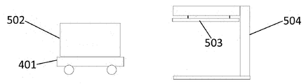
물품을 저장하기 위한 저장 컨테이너(502) 내에서 측정을 수행하기 위한 시스템 및 방법으로서, 저장 컨테이너(502)는 저장 컨테이너(502)를 저장하기 위한 3-차원적인 저장 그리드 구조물(104)을 형성하는 프레임워크 구조물(100)을 포함하는 자동화된 저장 시스템 내에 저장되고, 그리드 구조물(104)은 수직 저장 컬럼(105)을 형성하고, 각각의 수직 저장 컬럼은 수직 저장 컬럼(105)의 접근 개구부(112)의 크기에 의해서 형성되는 동일한 수평 면적을 갖고, 레일 시스템(108)이, 각각의 저장 컬럼(105)의 상단부에서 각각의 접근 개구부(112)의 원주를 형성하는 프레임워크 구조물(100) 상에 배열되고, 레일 시스템(108)은 저장 컨테이너(502)를 핸들링하고 저장 컬럼(105)으로 그리고 그로부터 전달하는 컨테이너 핸들링 운반체(201)를 위한 이용 가능 루트를 제공하며, 각각의 운반체(201)는 저장 시스템의 동작을 제어하는 중앙 컴퓨터 시스템과 통신하는 운반체 제어기(230)를 포함하고, 상기 시스템은, 대기 조건을 측정하기 위한 그리고 상기 저장 컨테이너(502) 내에서 측정을 수행하기 위한 측정 장비를 갖춘, 레일 시스템(108)을 통해서 컨테이너 핸들링 운반체에 접근할 수 있는, 테스팅 스테이션(504)을 더 포함하고, 테스팅 스테이션(504)은 측정 데이터를 컴퓨터 시스템에 통신하도록 구성된다.A system and method for performing measurements within a storage container (502) for storing items, the storage container (502) forming a three-dimensional storage grid structure (104) for storing the storage container (502). Stored in an automated storage system comprising a framework structure 100 , the grid structure 104 forming vertical storage columns 105 , each vertical storage column having an access opening 112 of the vertical storage column 105 . ), a rail system 108 on the framework structure 100 defining the circumference of each access opening 112 at the upper end of each storage column 105 . arranged, rail system 108 provides an usable route for container handling vehicles 201 that handle storage containers 502 and deliver them to and from storage columns 105 , each vehicle 201 having a storage a vehicle controller (230) in communication with a central computer system for controlling the operation of the system, the system equipped with measurement equipment for measuring atmospheric conditions and for performing measurements within the storage container (502); It further includes a testing station 504 , accessible to the container handling vehicle via a rail system 108 , the testing station 504 being configured to communicate measurement data to the computer system.
Description
본 발명은 컨테이너를 저장 및 회수하기 위한 자동화된 저장 및 회수 시스템, 특히 측정 장비를 포함하는 테스팅 스테이션 내에 배치될 때 컨테이너 내에서 측정을 수행하기 위한 시스템 및 방법에 관한 것이다.The present invention relates to an automated storage and retrieval system for storing and retrieving containers, in particular a system and method for performing measurements within a container when deployed in a testing station comprising measuring equipment.
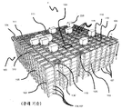
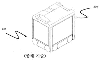
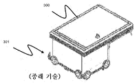
도 1은 프레임워크 구조물(100)을 갖는 전형적인 종래 기술의 자동화된 저장 및 회수 시스템(1)을 개시하고, 도 2 및 도 3은 그러한 시스템(1)에서의 동작에 적합한 2개의 상이한 종래 기술의 컨테이너 핸들링 운반체(201, 301)를 개시한다.1 discloses a typical prior art automated storage and
프레임워크 구조물(100)은 직립 부재(102), 수평 부재(103), 및 직립 부재(102)와 수평 부재(103) 사이에서 행(row)으로 배열되는 저장 컬럼(105)을 포함하는 저장 부피를 포함한다. 이러한 저장 컬럼(105) 내에서, 빈(bin)으로도 알려져 있는 저장 컨테이너(106)가 서로 상하로 적층되어 적층체(107)를 형성한다. 부재(102, 103)는 전형적으로 금속, 예를 들어 압축 알루미늄 프로파일로 제조될 수 있다.The
자동화된 저장 및 회수 시스템(1)의 프레임워크 구조물(100)은 프레임워크 구조물(100)의 상단부에 걸쳐 배열된 레일 시스템(108)을 포함하고, 레일 시스템(108) 상에서 복수의 컨테이너 핸들링 운반체(201, 301)가 동작되어 저장 컨테이너(106)를 저장 컬럼(105)으로부터 상승시키고, 저장 컨테이너(106)를 저장 컬럼 내로 하강시키며, 또한 저장 컨테이너(106)를 저장 컬럼(105) 위에서 운송한다. 레일 시스템(108)은 프레임 구조물(100)의 상단부에 걸친 제1 방향(X)으로 컨테이너 핸들링 운반체(201, 301)의 이동을 안내하도록 배열된 평행 레일의 제1 세트(110), 및 제1 방향(X)에 수직인 제2 방향(Y)으로 컨테이너 핸들링 운반체(201, 301)의 이동을 안내하기 위한, 레일의 제1 세트(110)에 수직으로 배열된, 평행 레일의 제2 세트(111)를 포함한다. 컨테이너 핸들링 운반체는 레일 시스템(108) 내의 접근 개구부(112)를 통해서 컬럼(105) 내에 저장된 컨테이너(106)에 접근한다. 컨테이너 핸들링 운반체(201, 301)는 저장 컬럼(105) 위에서 측방향으로, 즉 수평 X-Y 평면에 평행한 평면 내에서 이동할 수 있다.The
프레임워크 구조물(100)의 직립 부재(102)는, 컨테이너를 컬럼(105)으로부터 상승시키고 컨테이너를 컬럼 내로 하강시키는 동안 저장 컨테이너를 안내하기 위해서 사용된다. 컨테이너(106)의 적층체(107)는 전형적으로 자가-지지형이다.The
각각의 종래 기술의 컨테이너 핸들링 운반체(201, 301)는 운반체 본체(201a, 301a), 및 X 방향 및 Y 방향 각각을 따른 컨테이너 핸들링 운반체(201, 301)의 측방향 이동을 가능하게 하는 휠의 제1 및 제2 세트(201b, 301b, 201c, 301c)를 포함한다. 도 2 및 도 3에서, 각각의 세트 내의 2개의 휠을 완전히 확인할 수 있다. 휠의 제1 세트(201b, 301b)는 레일의 제1 세트(110) 중의 2개의 인접 레일들과 결합되도록 배열되고, 휠의 제2 세트(201c, 301c)는 레일의 제2 세트(111) 중의 2개의 인접 레일들과 결합되도록 배열된다. 휠의 세트(201b, 301b, 201c, 301c) 중 적어도 하나가 상승 및 하강될 수 있고, 그에 따라 휠의 제1 세트(201b, 301b) 및/또는 휠의 제2 세트(201c, 301c)가 언제든지 레일의 각각의 세트(110, 111)와 결합될 수 있다.Each of the prior art
각각의 종래 기술의 컨테이너 핸들링 운반체(201, 301)는 또한 저장 컨테이너(106)의 수직 운송을 위한, 예를 들어 저장 컨테이너(106)를 저장 컬럼(105)으로부터 상승시키고 저장 컨테이너(106)를 저장 컬럼 내로 하강시키기 위한 승강 장치(미도시)를 포함한다. 승강 장치는 하나 이상의 파지/결합 장치를 포함하고, 그러한 파지/결합 장치는 저장 컨테이너(106)와 결합되도록 구성되고, 그러한 파지/결합 장치는 운반체(201, 301)로부터 하강될 수 있고, 그에 따라 운반체(201, 301)에 대한 파지/결합 장치의 위치가, 제1 방향(X) 및 제2 방향(Y)에 수직인, 제3 방향(Z)으로 조정될 수 있다. 컨테이너 핸들링 운반체(301)의 파지 장치의 일부가 도 3에 도시되어 있고 참조 번호 304로 표시되어 도시되어 있다. 컨테이너 핸들링 장치(201)의 파지 장치는 도 2에서 운반체 본체(301a) 내에 위치된다.Each prior art
통상적으로 그리고 또한 본원의 목적을 위해서, Z=1은 저장 컨테이너의 최상부 층, 즉 레일 시스템(108) 바로 아래의 층을 나타내고, Z=2는 레일 시스템(108) 아래의 2번째 층, 그리고 Z=3은 3번째 층 등을 나타낸다. 도 1에 개시된 예시적인 종래 기술에서, Z=8은 저장 컨테이너의 최하부의 하단 층을 나타낸다. 유사하게, X=1…n 및 Y=1…n은 수평 평면 내의 각각의 저장 컬럼(105)의 위치를 나타낸다. 결과적으로, 예로서, 그리고 도 1에 표시된 데카르트 좌표계(X, Y, Z)를 이용하면, 도 1에서 106'으로 표시된 저장 컨테이너는 X=10, Y=2, Z=3의 저장 위치를 점유한다고 할 수 있다. 컨테이너 핸들링 운반체(201, 301)가 층(Z=0) 내에서 이동된다고 할 수 있고, 각각의 저장 컬럼(105)은 그 X 및 Y 좌표에 의해서 표시될 수 있다.Typically and also for purposes of this application, Z=1 denotes the topmost layer of the storage container, ie the layer directly below the
프레임워크 구조물(100)의 저장 부피는 종종 그리드(104)로 지칭되고, 이러한 그리드 내의 가능한 저장 위치는 저장 셀로 지칭된다. 각각의 저장 컬럼은 X- 및 Y-방향을 따른 위치에 의해서 표시될 수 있는 한편, 각각의 저장 셀은 X-, Y- 및 Z-방향을 따른 컨테이너 번호에 의해서 표시될 수 있다.The storage volume of the
각각의 종래 기술의 컨테이너 핸들링 운반체(201, 301)는, 저장 컨테이너(106)를 레일 시스템(108)을 가로질러 운송할 때 저장 컨테이너(106)를 수용 및 수납하기 위한 저장 격실 또는 공간을 포함한다. 저장 공간은, 도 2에 도시된 바와 같은 그리고 예를 들어 기재 내용이 본원에서 참조로 포함되는 WO2015/193278A1에서 설명된 바와 같은, 운반체 본체(201a) 내의 중앙에 배열된 공동을 포함할 수 있다.Each prior art
도 3은 외팔보 구성을 갖는 컨테이너 핸들링 운반체(301)의 대안적인 구성을 도시한다. 그러한 운반체는, 기재 내용이 또한 본원에서 참조로 포함되는 예를 들어 NO317366에 구체적으로 설명되어 있다.3 shows an alternative configuration of a
도 2에 도시된 중앙 공동 컨테이너 핸들링 운반체(201)는, 예를 들어 기재 내용이 본원에서 참조로 포함되는 WO2015/193278A1에서 설명된 바와 같이, 저장 컬럼(105)의 측방향 범위와 일반적으로 동일한 X 및 Y 방향을 따른 치수를 가지는 면적을 커버하는 풋프린트(footprint)를 가질 수 있다. 본원에서 사용된 '측방향'이라는 용어는 '수평'을 의미할 수 있다.The central common
대안적으로, 중앙 공동 컨테이너 핸들링 운반체(101)는, 예를 들어 WO2014/090684A1에 개시된 바와 같이, 저장 컬럼(105)에 의해서 형성된 측방향 면적보다 큰 풋프린트를 가질 수 있다.Alternatively, the central common container handling vehicle 101 may have a footprint that is greater than the lateral area formed by the
레일 시스템(108)은 전형적으로, 운반체의 휠이 내부로 삽입되는 홈을 갖는 레일을 포함한다. 대안적으로, 레일은 상향 돌출 요소를 포함할 수 있고, 운반체의 휠은 레일 이탈을 방지하기 위한 플랜지를 포함한다. 이러한 홈 및 상향 돌출 요소는 집합적으로 트랙으로서 알려져 있다. 각각의 레일은 하나의 트랙을 포함할 수 있거나, 각각의 레일은 2개의 평행한 트랙들을 포함할 수 있다.The
기재 내용이 본원에서 참조로 포함되는 WO2018146304는, X 및 Y 방향 모두를 따라서 평행한 트랙 및 레일을 포함하는 레일 시스템(108)의 전형적인 구성을 도시한다.WO2018146304, the disclosure of which is incorporated herein by reference, shows a typical configuration of a
프레임워크 구조물(100) 내에서, 컬럼(105)의 대부분은 저장 컬럼(105)이고, 즉 저장 컨테이너(106)가 적층체(107)로 저장되는 컬럼(105)이다. 그러나, 일부 컬럼(105)이 다른 목적을 가질 수 있다. 도 1에서, 컬럼(119 및 120)은, 프레임워크 구조물(100)의 외부로부터 저장 컨테이너(106)에 접근할 수 있는 또는 저장 컨테이너가 프레임워크 구조물(100)의 내외로 전달될 수 있는 접근 스테이션(미도시)으로 운송될 수 있도록, 저장 컨테이너(106)를 드롭 오프(drop off) 및/또는 픽업(pick up)하기 위해서 컨테이너 핸들링 운반체(201, 301)에 의해서 이용되는 그러한 특별한-목적의 컬럼이다. 당업계에서, 그러한 위치는 일반적으로 '포트'로 지칭되고, 포트가 내부에 위치되는 컬럼은 '포트 컬럼'(119, 120)으로 지칭될 수 있다. 접근 스테이션으로의 운송은 임의의 방향일 수 있고, 즉 수평, 틸팅, 및/또는 수직일 수 있다. 예를 들어, 저장 컨테이너(106)는 프레임워크 구조물(100) 내에서 무작위적인 또는 지정된 컬럼(105) 내에 배치될 수 있고, 이어서 임의의 컨테이너 핸들링 운반체에 의해서 픽업될 수 있고, 접근 스테이션으로의 추가적인 운송을 위해서 포트 컬럼(119, 120)으로 운반될 수 있다. '틸팅된'이라는 용어는 수평과 수직 사이의 일반적인 운송 배향을 가지는 저장 컨테이너(106)의 운송을 의미한다는 것에 주목하여야 한다.Within
도 1에서, 제1 포트 컬럼(119)은 예를 들어, 컨테이너 핸들링 운반체(201, 301)가 접근 또는 전달 스테이션으로 운송하기 위한 저장 컨테이너(106)를 드롭 오프시킬 수 있는, 지정된 드롭-오프 포트 컬럼일 수 있고, 제2 포트 컬럼(120)은, 접근 또는 전달 스테이션으로부터 운송된 저장 컨테이너(106)를 컨테이너 핸들링 운반체(201, 301)가 픽업할 수 있는 지정된 픽업 포트 컬럼일 수 있다.In FIG. 1 , a
접근 스테이션은 전형적으로, 제품 아이템이 저장 컨테이너(106)로부터 제거되거나 그 내부에 배치되는 픽킹(picking) 또는 보관 스테이션일 수 있다. 픽킹 또는 보관 스테이션에서, 저장 컨테이너(106)는 일반적으로 자동화된 저장 및 회수 시스템(1)으로부터 제거되지 않고, 다시 접근되는 경우에 프레임워크 구조물(100) 내로 복귀된다. 포트가 또한 저장 컨테이너를 다른 저장 설비로(예를 들어, 다른 프레임워크 구조물로 또는 다른 자동화된 저장 및 회수 시스템으로), 운송 운반체(예를 들어, 기차 또는 대형 트럭)로, 또는 생산 설비로 전달하기 위해서 사용될 수 있다.The access station may typically be a picking or storage station where product items are removed from or placed within the
컨베이어를 포함하는 컨베이어 시스템을 일반적으로 이용하여, 저장 컨테이너를 포트 컬럼(119, 120)과 접근 스테이션 사이에서 운송한다.Conveyor systems including conveyors are typically used to transport storage containers between
포트 컬럼(119, 120) 및 접근 스테이션이 상이한 레벨들에 위치되는 경우에, 컨베이어 시스템은, 저장 컨테이너(106)를 포트 컬럼(119, 120)과 접근 스테이션 사이에서 수직으로 운송하기 위한 수직 구성요소를 갖춘 승강 장치를 포함할 수 있다.Where the
컨베이어 시스템은, 예를 들어 기재 내용이 본원에서 참조로 포함되는 WO2014/075937A1에 설명된 바와 같이, 저장 컨테이너(106)를 상이한 프레임워크 구조물들 사이에서 전달하도록 배열될 수 있다.The conveyor system may be arranged to transfer the
도 1에 개시된 컬럼(105) 중 하나 내에 저장된 저장 컨테이너(106)에 접근할 때, 컨테이너 핸들링 운반체(201, 301) 중 하나는 목표 저장 컨테이너(106)를 그 위치로부터 회수하도록 그리고 이를 드롭-오프 포트 컬럼(119)으로 운송하도록 명령을 받는다. 이러한 동작은, 컨테이너 핸들링 운반체(201, 301)를, 목표 저장 컨테이너(106)가 내부에 배치되는 저장 컬럼(105) 위의 위치로 이동시키는 것, 컨테이너 핸들링 운반체(201, 301) 상승 장치(미도시)를 이용하여 저장 컨테이너(106)를 저장 컬럼(105)으로부터 회수하는 것, 그리고 저장 컨테이너(106)를 드롭-오프 포트 컬럼(119)으로 운송하는 것을 포함한다. 목표 저장 컨테이너(106)가 적층체(107) 내에 깊이 위치되는 경우에, 즉 목표 저장 컨테이너(106) 위에 하나의 또는 복수의 다른 저장 컨테이너(106)가 배치된 경우에, 동작은 또한, 목표 저장 컨테이너(106)를 저장 컬럼(105)으로부터 상승시키기 전에, 위에-배치된 저장 컨테이너를 일시적으로 이동시키는 것을 포함한다. 당업계에서 종종 "디깅(digging)"으로 지칭되는 이러한 단계는, 목표 저장 컨테이너를 드롭-오프 포트 컬럼(119)으로 운송하기 위해서 추후에 이용되는 동일한 컨테이너 핸들링 운반체를 이용하여, 하나 또는 복수의 다른 협력 컨테이너 핸들링 운반체를 이용하여 수행될 수 있다. 대안적으로 또는 부가적으로, 자동화된 저장 및 회수 시스템(1)은, 저장 컨테이너를 저장 컬럼(105)으로부터 일시적으로 제거하는 과제를 위해서 특별히 지정된 컨테이너 핸들링 운반체를 가질 수 있다. 목표 저장 컨테이너(106)가 저장 컬럼(105)으로부터 제거되면, 일시적으로 제거된 저장 컨테이너가 원래의 저장 컬럼(105) 내로 재배치될 수 있다. 그러나, 대안적으로, 제거된 저장 컨테이너가 다른 저장 컬럼으로 재배치될 수 있다.Upon accessing a
저장 컨테이너(106)를 컬럼(105) 중 하나 내에 저장하고자 할 때, 컨테이너 핸들링 운반체(201, 301) 중 하나는, 저장 컨테이너(106)를 픽업 포트 컬럼(120)으로부터 픽업하도록 그리고 이를 저장하고자 하는 저장 컬럼(105) 위의 위치로 운송하도록 명령을 받는다. 저장 컬럼 적층체(107) 내의 목표 위치에 또는 그 위에 배치된 임의의 저장 컨테이너가 제거된 후에, 컨테이너 핸들링 운반체(201, 301)는 저장 컨테이너(106)를 희망 위치에 배치한다. 이어서, 제거된 저장 컨테이너는 저장 컬럼(105) 내로 다시 하강될 수 있거나, 다른 저장 컬럼으로 재배치될 수 있다.When the
자동화된 저장 및 회수 시스템(1)을 모니터링 및 제어하기 위해서, 예를 들어 프레임워크 구조물(100) 내의 각각의 저장 컨테이너(106)의 위치, 각각의 저장 컨테이너(106)의 내용물; 및 컨테이너 핸들링 운반체들(201, 301)이 서로 충돌하지 않고 희망 저장 컨테이너(106)가 희망 시간에 희망 위치로 전달될 수 있도록 하는 컨테이너 핸들링 운반체(201, 301)의 이동을 모니터링 및 제어하기 위해서, 자동화된 저장 및 회수 시스템(1)은 제어 시스템(500)을 포함하고, 그러한 제어 시스템은 전형적으로 컴퓨터화되고 전형적으로 저장 컨테이너(106)를 계속 추적하기 위한 데이터베이스를 포함한다.For monitoring and controlling the automated storage and
도 4는 전달 운반체를 설명한다. 전달 운반체는 컨테이너 핸들링 운반체에서와 동일한 휠의 셋업을 갖는 기부를 포함한다. 휠 기부 유닛은 휠 배열체를 특징으로 하고, 이러한 휠 배열체는 레일 그리드(즉, 상단 레일 그리드 및 전달 레일 그리드 중 임의의 것) 상에서 제1 방향으로 이동하기 위한 휠의 제1 세트 및 제1 방향에 수직인 제2 방향으로 이동하기 위한 휠의 제2 세트를 갖는다. 각각의 휠의 세트는 휠 기부 유닛의 대향 측면들에 배열된 2개의 휠의 쌍을 포함한다. 휠 기부 유닛이 레일 그리드 상으로 이동할 수 있는 방향을 변경하기 위해서, 휠의 세트 중 하나가 휠 변위 조립체에 연결된다. 휠 변위 조립체는, 희망 방향으로 이동하는 휠의 세트만이 레일 그리드와 접촉되도록, 연결된 휠의 세트를 휠의 다른 세트에 대해서 상승 및 하강시킬 수 있다. 휠 변위 조립체는 전기 모터에 의해서 구동된다. 또한, 재충전 가능 배터리에 의해서 전력을 공급 받는 2개의 전기 모터가 휠의 세트에 연결되어, 휠 기부 유닛을 희망 방향으로 이동시킨다. 휠 기부 유닛의 수평 주변부는, 2개의 휠-기부 유닛들이 레일 그리드의 임의의 인접 그리드 셀 상에서 서로 통과할 수 있도록, 레일 그리드의 그리드 셀에 의해서 형성된 수평 면적 내에 피팅되는 치수를 갖는다. 다시 말해서, 휠 기부 유닛은, 예를 들어 기재 내용이 본원에서 참조로 포함되는 WO2015/193278A1에서 설명된 바와 같이, 그리드 셀의 수평 면적과 일반적으로 동일한, 풋프린트, 즉 X 및 Y 방향의 범위, 즉 X 및 Y 방향을 따른 그리드 셀의 범위를 가질 수 있다.4 illustrates a delivery vehicle. The delivery vehicle includes a base having the same set-up of wheels as in the container handling vehicle. The wheel base unit features a wheel arrangement, wherein the wheel arrangement comprises a first set of wheels and a first set of wheels for moving in a first direction on a rail grid (ie, any of a top rail grid and a transmission rail grid). having a second set of wheels for moving in a second direction perpendicular to the direction. Each set of wheels includes a pair of two wheels arranged on opposite sides of the wheel base unit. To change the direction in which the wheel base unit can move on the rail grid, one of the sets of wheels is connected to a wheel displacement assembly. The wheel displacement assembly is capable of raising and lowering a set of connected wheels relative to another set of wheels such that only the set of wheels moving in a desired direction are in contact with the rail grid. The wheel displacement assembly is driven by an electric motor. Also, two electric motors powered by rechargeable batteries are connected to the set of wheels to move the wheel base unit in a desired direction. The horizontal perimeter of the wheel base unit is dimensioned to fit within the horizontal area defined by the grid cell of the rail grid such that two wheel-base units can pass each other on any adjacent grid cell of the rail grid. In other words, the wheel base unit has a footprint, i.e. extent in the X and Y directions, generally equal to the horizontal area of the grid cell, as described for example in WO2015/193278A1, the disclosure of which is incorporated herein by reference; That is, it may have a range of grid cells along the X and Y directions.
종래 기술의 해결책의 문제점은, 저장부 내에 부패 가능 물품이 있는 경우에, 제품의 신선도 및 물품이 저장되는 조건을 측정할 필요가 있다는 것이다. 그러나, 고가의 장비 및 광범위한 재구축을 필요로 하는 비용이 많이 드는 해결책으로 전환할 필요가 없이 물품을 정확하게 판독하는데 있어서 문제점이 있다. 그에 따라, 본 발명의 목적은 전술한 문제점을 해결하는 것이다.A problem with prior art solutions is that, if there are perishables in storage, it is necessary to measure the freshness of the product and the conditions under which the items are stored. However, there is a problem in accurately reading articles without the need to switch to an expensive solution that requires expensive equipment and extensive rebuilding. Accordingly, it is an object of the present invention to solve the above-mentioned problems.
본 발명은 독립 청구항에 기재되어 있고 특성화되는 한편, 종속 청구항은 본 발명의 다른 특성을 설명한다.The invention is set forth and characterized in the independent claims, while the dependent claims set forth other features of the invention.
일 양태에서, 본 발명은 물품을 저장하기 위한 저장 컨테이너 내에서 측정을 수행하기 위한 시스템에 관한 것으로서, 저장 컨테이너는 저장 컨테이너를 저장하기 위한 3-차원적인 저장 그리드 구조물을 형성하는 프레임워크 구조물을 포함하는 자동화된 저장 시스템 내에 저장되고, 그리드 구조물은 수직 저장 컬럼을 형성하고, 각각의 수직 저장 컬럼은 수직 저장 컬럼의 접근 개구부의 크기에 의해서 형성되는 수평 면적을 갖고, 레일 시스템이, 각각의 저장 컬럼의 상단부에서 각각의 접근 개구부의 원주를 형성하는 프레임워크 구조물 상에 배열되고, 레일 시스템은 저장 컨테이너를 핸들링하고 저장 컬럼으로 그리고 그로부터 전달하는 컨테이너 핸들링 운반체를 위한 이용 가능 루트를 제공하며, 상기 시스템은 대기 조건을 측정하기 위한 그리고 상기 저장 컨테이너 내에서 측정을 수행하기 위한 측정 장비를 갖춘, 레일 시스템을 통해서 컨테이너 핸들링 운반체에 접근할 수 있는, 테스팅 스테이션을 더 포함하고, 테스팅 스테이션은 측정 데이터를 컴퓨터 시스템에 통신하도록 구성된다.In one aspect, the present invention relates to a system for performing measurements within a storage container for storing articles, the storage container comprising a framework structure forming a three-dimensional storage grid structure for storing the storage container wherein the grid structure defines vertical storage columns, each vertical storage column having a horizontal area defined by the size of an access opening of the vertical storage column, the rail system comprising: arranged on a framework structure defining the circumference of each access opening at the upper end of the and a testing station, accessible to the container handling vehicle via a rail system, equipped with measurement equipment for measuring atmospheric conditions and for performing measurements within the storage container, the testing station transferring the measurement data to a computer system configured to communicate with
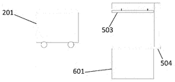
또한, 테스팅 스테이션은 측정 플랫폼이 부착되는 상부 부분, 컨테이너를 수용하는 하부 부분, 및 상부 부분과 하부 부분을 연결하는 부분을 포함할 수 있다. 또한, 테스팅 스테이션은 상부 부분과 하부 부분 사이에서 컨테이너를 수용하기 위한 공간을 가질 수 있고, 테스팅 스테이션은 측정 플랫폼을 상승 및 하강시키도록 구성될 수 있다.Further, the testing station may include an upper portion to which the measurement platform is attached, a lower portion for accommodating the container, and a portion connecting the upper portion and the lower portion. Further, the testing station may have a space between the upper portion and the lower portion to receive the container, and the testing station may be configured to raise and lower the measurement platform.
테스팅 스테이션은 상단부에서 컨테이너를 갖는 컨테이너 핸들링 운반체를 수용하도록 구성될 수 있다.The testing station may be configured to receive a container handling vehicle having a container at its upper end.
측정 플랫폼은 전기 모터에 의해서 제어되는 로프, 밴드 또는 와이어에 의해서 상승 및 하강될 수 있거나, 측정 플랫폼은 로봇 아암에 의해서 상승 및 하강될 수 있고, 측정 플랫폼은 온도 측정 장비, 수분 검출기, 가스 검출기 및 카메라를 포함한다.The measuring platform can be raised and lowered by a rope, band or wire controlled by an electric motor, or the measuring platform can be raised and lowered by a robot arm, and the measuring platform includes a temperature measuring instrument, a moisture detector, a gas detector and includes a camera.
본 발명의 제3 양태는 자동화된 저장 시스템에서 저장하기 위한 컨테이너 내에서 측정을 수행하는 방법에 관한 것으로서, 자동화된 저장 시스템은 하부측 저장 시스템(1)의 3-차원적인 그리드(4), 컨테이너를 운송하기 위한 적어도 하나의 컨테이너 핸들링 운반체, 추가적인 분배를 위해서 물품을 픽킹하기 위한 포트, 저장 시스템의 동작을 제어하기 위한 중앙 컴퓨터 시스템을 포함하고, 상기 방법은:A third aspect of the present invention relates to a method for carrying out measurements in a container for storage in an automated storage system, the automated storage system comprising: a three-dimensional grid (4) of an underlying storage system (1), a container at least one container handling vehicle for transporting a container, a port for picking up articles for further dispensing, and a central computer system for controlling operation of the storage system, the method comprising:
컨테이너를 컨테이너 핸들링 운반체로 테스팅 스테이션 내에 배치하는 단계,placing the container into the testing station as a container handling vehicle;
테스팅 스테이션에 부착된 측정 플랫폼을 컨테이너 상으로 하강시키는 단계,lowering the measurement platform attached to the testing station onto the container;
측정을 수행하고, 측정을 중앙 컴퓨터 시스템에 전송하고, 측정을 기초로 분석을 수행하고, 분석을 기초로 컨테이너 핸들링 운반체에 명령어를 전송하고, 측정 플랫폼을 상승시키고, 컨테이너를 컨테이너 핸들링 운반체로 다른 목적지로 운송하는 단계를 포함한다. 컨테이너 내의 온도, 수분 및 가스 레벨의 측정 수행 및 물품의 시각적 검사를 위해서 카메라를 이용하는 것.take measurements, send the measurements to a central computer system, perform an analysis based on the measurements, send commands to the container handling vehicle based on the analysis, raise the measurement platform, and transfer the container to the container handling vehicle to another destination transport to the Using a camera to perform measurements of temperature, moisture and gas levels in containers and for visual inspection of articles.
이하의 도면은 본 발명의 이해를 돕기 위해서 첨부된 것이다. 도면은, 단지 예로서 이제 설명할 본 발명의 실시형태를 도시한다.
도 1은 종래 기술의 자동화된 저장 및 회수 시스템의 프레임워크 구조물의 사시도이다.
도 2는 저장 컨테이너를 내부에서 운반하기 위한 중앙 배열 공동을 가지는 종래 기술의 컨테이너 핸들링 운반체의 사시도이다.
도 3은 저장 컨테이너를 아래에서 운반하기 위한 외팔보를 가지는 종래 기술의 컨테이너 핸들링 운반체의 사시도이다.
도 4는 전달 운반체의 측면도이다.
도 5a 내지 도 5d는 본 발명의 실시형태의 측면도로서, 여기에서 중앙 공동을 가지는 컨테이너 핸들링 운반체가 측정을 위해서 컨테이너를 테스팅 스테이션 내에 배치한다.
도 6a 내지 도 6d는 본 발명의 실시형태의 측면도로서, 여기에서 외팔보 해결책을 가지는 컨테이너 핸들링 운반체가 측정을 위해서 컨테이너를 테스팅 스테이션 내에 배치한다.
도 7a 내지 도 7c는 본 발명의 실시형태의 측면도로서, 여기에서 컨테이너를 운반하는 전달 운반체가 테스팅 스테이션 내에 배치된다.
도 8a 내지 도 8d는 본 발명의 대안적인 실시형태의 측면도로서, 여기에서 외팔보 해결책을 가지는 컨테이너 핸들링 운반체가 측정을 위해서 컨테이너를 테스팅 스테이션 내에 배치한다.
도 9a 내지 도 9c는 본 발명의 대안적인 실시형태의 측면도로서, 여기에서 컨테이너를 운반하는 전달 운반체가 테스팅 스테이션 내에 배치된다.
도 10은 본 발명의 실시형태의 프로세스 내의 단계들을 설명하는 흐름도이다.The following drawings are attached to help the understanding of the present invention. The drawings show, by way of example only, embodiments of the invention which will now be described.
1 is a perspective view of a framework structure of a prior art automated storage and retrieval system;
2 is a perspective view of a prior art container handling vehicle having a centrally arranged cavity for carrying storage containers therein;
3 is a perspective view of a prior art container handling vehicle having a cantilever for carrying storage containers from below;
4 is a side view of the delivery vehicle.
5A-5D are side views of an embodiment of the present invention, wherein a container handling vehicle having a central cavity places a container into a testing station for measurement;
6A-6D are side views of an embodiment of the present invention, wherein a container handling vehicle having a cantilevered solution places a container into a testing station for measurement;
7A-7C are side views of an embodiment of the present invention, wherein a delivery vehicle carrying a container is disposed within a testing station;
8A-8D are side views of an alternative embodiment of the present invention, wherein a container handling vehicle having a cantilevered solution places a container into a testing station for measurement;
9A-9C are side views of an alternative embodiment of the present invention, wherein a delivery vehicle carrying a container is disposed within a testing station;
10 is a flowchart illustrating steps within a process of an embodiment of the present invention.
이하에서, 첨부 도면을 참조하여 본 발명의 실시형태를 더 구체적으로 설명할 것이다. 그러나, 도면은 본 발명을 도면에 도시된 청구-대상으로 제한하기 위한 것이 아님을 이해하여야 할 것이다.DETAILED DESCRIPTION OF THE PREFERRED EMBODIMENTS Hereinafter, embodiments of the present invention will be described in more detail with reference to the accompanying drawings. It should be understood, however, that the drawings are not intended to limit the invention to the claimed subject matter shown in the drawings.
자동화된 저장 및 회수 시스템(1)의 프레임워크 구조물(100)은 도 1 내지 도 3과 관련하여 전술한 종래 기술의 프레임워크 구조물(100)에 따라 구성되고, 즉 많은 수의 직립 부재(102) 및 직립 부재(102)에 의해서 지지되는 많은 수의 수평 부재(103)로 구성되고, 또한 프레임워크 구조물(100)은 X 방향 및 Y 방향의 제1 상부 레일 시스템(108)을 포함한다.The
프레임워크 구조물(100)은 부재들(102, 103) 사이에 제공된 저장 컬럼(105) 형태의 저장 격실을 더 포함하고, 저장 컨테이너(106)는 저장 컬럼(105) 내에서 적층체(107)로 적층될 수 있다.The
프레임워크 구조물(100)은 임의의 크기일 수 있다. 특히, 프레임워크 구조물은 도 1에 개시된 것보다 상당히 더 넓을 수 있고/있거나 더 길 수 있고/있거나 더 깊을 수 있다. 예를 들어, 프레임워크 구조물(100)은 700 x 700 컬럼 초과의 수평 범위 및 12개 초과의 컨테이너의 저장 깊이를 가질 수 있다.The
이제, 도 5a 내지 도 5d, 도 6a 내지 도 6d, 도 7a 내지 도 7c, 도 8a 내지 도 8d, 도 9a 내지 도 9c 및 도 10을 참조하여, 본 발명에 따른 자동화된 저장 및 회수 시스템의 실시형태를 더 구체적으로 설명할 것이다.Referring now to FIGS. 5A-5D, 6A-6D, 7A-7C, 8A-8D, 9A-9C and 10, an implementation of an automated storage and retrieval system according to the present invention The form will be described in more detail.
본 발명의 바람직한 실시형태에서, 테스팅 스테이션은 상단 부분을 포함한다. 이러한 상단 부분은 측정 플랫폼을 수용한다. 측정 플랫폼은 적어도 하나의 센서를 포함한다. 적어도 하나의 센서는 저장 컨테이너 내의 적어도 하나의 대기 조건을 측정하기 위해서 사용된다. 하나의 그러한 대기 조건은 컨테이너 내의 온도일 수 있고, 또한 센서는 식품이 썩는 동안 방출되는 가스의 존재를 검출하기 위해서 사용될 수 있다. 하나의 그러한 가스는 메탄일 수 있다. 식품의 부패 중에 방출되는 다른 가스는 이산화탄소 및 황화수소이다. 이산화탄소 및 황화수소의 경우에, 이들은 공기보다 무겁고 그에 따라 컨테이너의 하단부에 모일 것이다. 이산화탄소 및 황화수소를 감지하기 위한 센서는 그에 따라, 컨테이너 내로 하강되는 탐침에 부착될 수 있다. 대안적으로, 컨테이너의 측면 및 하단부 내에 홀이 있을 수 있고, 이러한 홀 내로 센서를 삽입할 수 있다. 또 다른 해결책에서, 예를 들어 컨테이너의 내측 연부를 따라서 슬릿 또는 터널이 있을 수 있고, 컨테이너의 내용물이 탐침을 방해하지 않게, 탐침이 컨테이너의 하단부 내로 하강될 수 있다. 또한, 수분을 검출하기 위한 검출기가 있을 수 있다. 수분의 존재는, 식품이 썩는 동안 식품의 세포가 파괴되고 세포 내의 액체가 누출된다는 사실에 기인한다. 추가적인 유형의 측정 장비가 카메라일 수 있다. 카메라는, 식품이 썩는다는 것에 관한 임의의 징후가 있는지를 검출하기 위해서, 컨테이너 내부의, 즉 내용물의 사진을 촬영할 수 있다. 카메라는, 예를 들어 바나나의 갈색 반점이나 흰곰팡이로 인한 표면 변색과 같이 음식에 표시가 있는지를 검출하기 위해서 컬러 화상을 촬영하는 일반 카메라일 수 있다. 대안적으로 또는 부가적으로, 곰팡이를 검출하기 위해서 자외선 광을 가지는 카메라를 이용할 수 있다.In a preferred embodiment of the invention, the testing station comprises an upper part. This upper part accommodates the measurement platform. The measurement platform includes at least one sensor. The at least one sensor is used to measure at least one atmospheric condition within the storage container. One such atmospheric condition may be the temperature within the container, and the sensor may also be used to detect the presence of gases released during food spoilage. One such gas may be methane. Other gases released during spoilage of food are carbon dioxide and hydrogen sulfide. In the case of carbon dioxide and hydrogen sulfide, they are heavier than air and will therefore collect at the bottom of the container. A sensor for sensing carbon dioxide and hydrogen sulfide may be attached to a probe that is thus lowered into the container. Alternatively, there may be holes in the sides and bottom of the container, into which the sensors may be inserted. In another solution, for example, there may be a slit or tunnel along the inner edge of the container and the probe may be lowered into the lower end of the container so that the contents of the container do not interfere with the probe. There may also be a detector for detecting moisture. The presence of moisture is due to the fact that during the decay of the food, the cells of the food are destroyed and the liquid within the cells is leaked. An additional type of measurement device may be a camera. The camera may take pictures of the inside of the container, ie the contents, to detect if there are any signs of spoilage of the food. The camera may be, for example, a normal camera that takes a color image to detect whether there are marks on the food, such as brown spots on bananas or surface discoloration due to white mold. Alternatively or additionally, a camera with ultraviolet light can be used to detect mold.
또한, 식품 상의 박테리아를 사멸시키기 위해서 UV 광을 사용할 수 있다. 또한, 곰팡이를 사멸시키기 위해서 UV 광을 이용할 수 있다. 그에 따라, 측정 플랫폼은, 썩고 있는 식품을 검출하기 위해서 그리고 식품 상의 그리고 컨테이너 내의 박테리아 및 곰팡이를 사멸시키기 위해서 사용될 수 있는 UV 광원을 가질 수 있다. 부패를 검출하기 위해서 그리고 박테리아 및 곰팡이를 사멸하기 위해서 UV 광원을 사용하는 것들 사이의 차이는, 광의 파장 및 광원의 파워이다.UV light can also be used to kill bacteria on food. Also, UV light can be used to kill mold. Accordingly, the measurement platform can have a UV light source that can be used to detect rotting food and to kill bacteria and mold on the food and in the container. The difference between using a UV light source to detect decay and to kill bacteria and fungi is the wavelength of the light and the power of the light source.
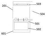
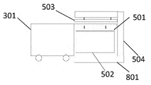
도 5a 내지 도 5d는 본 발명의 실시형태의 측면도로서, 여기에서 중앙 공동을 가지는 컨테이너 핸들링 운반체가 측정을 위해서 컨테이너를 테스팅 스테이션 내에 배치한다. 중앙 공동 내에서 컨테이너를 갖는 컨테이너 핸들링 운반체가 테스팅 스테이션 내로 이동한다. 컨테이너는 컨테이너 핸들링 운반체 아래의 공동 내로 하강된다. 컨테이너 핸들링 운반체가 테스팅 스테이션 내에 컨테이너를 배치한 후에, 컨테이너 핸들링 운반체는 멀리 이동한다. 컨테이너 핸들링 운반체가 멀리 이동한 후에, 측정 장비가 측정 플랫폼 상으로 하강된다. 테스팅 스테이션은 측정 플랫폼을 컨테이너 상으로 하강시킨다. 측정 플랫폼은 전기 모터에 부착된 라인을 이용하여 하강된다. 이러한 라인은 와이어, 벨트, 체인, 로프 또는 유사물일 수 있다. 측정 플랫폼은 상단 개구부 위에 피팅된다. 플랫폼은 하부측에 부착된 측정 장비를 더 포함한다. 측정 장비는, 플랫폼이 컨테이너 상에 배치될 때 컨테이너 내부에 피팅되도록, 배치된다. 측정 장비는 온도 센서, 수분 센서, 가스 센서, 및/또는 카메라일 수 있다. 측정 플랫폼에 장착될 수 있는 임의의 다른 종류의 측정 장비가 사용될 수 있다. 측정 장비가 데이터를 수집한 후에, 이는 중앙 컴퓨터 시스템에 송신될 수 있다. 중앙 컴퓨터 시스템은, 컨테이너의 내용물의 상태를 계속 추적하기 위해서 컨테이너의 ID와 함께 데이터를 저장할 수 있다. 컨테이너의 내용물의 상태를 기초로, 중앙 컴퓨터 시스템은 명령어를 컨테이너 핸들링 운반체에 송신하여, 컨테이너를 컨테이너 내의 물품의 상태에 따른 목적지로 운송할 수 있다. 물품이 고객에게 분배할 수 있는 상태에 있는 경우에, 물품을 갖는 컨테이너가, 희망 물품이 추가적인 분배를 위해서 픽킹될 수 있는 스테이션으로 운송되거나, 물품을 갖는 컨테이너가 저장 시스템 내로 다시 운송될 수 있다. 컨테이너 내의 하나 이상의 물품의 품질이 좋지 못한 경우에, 컨테이너는, 오염 물품을 컨테이너로부터 제거할 수 있는 목적지로 운송될 수 있다. 물품이 제거된 후에, 컨테이너는 저장 시스템으로 다시 운반되거나, 고객에게 추가적으로 분배하기 위해서 물품이 픽킹되는 픽킹 스테이션으로의 추가적인 분배를 위한 포트로 운송된다.5A-5D are side views of an embodiment of the present invention, wherein a container handling vehicle having a central cavity places a container into a testing station for measurement; A container handling vehicle with containers in the central cavity moves into the testing station. The container is lowered into a cavity below the container handling vehicle. After the container handling vehicle has placed the container in the testing station, the container handling vehicle moves away. After the container handling vehicle has moved away, the measuring equipment is lowered onto the measuring platform. The testing station lowers the measurement platform onto the container. The measuring platform is lowered using a line attached to an electric motor. These lines may be wires, belts, chains, ropes or the like. The measuring platform is fitted over the top opening. The platform further includes measuring equipment attached to the underside. The measuring equipment is arranged such that it fits inside the container when the platform is placed on the container. The measuring equipment may be a temperature sensor, a moisture sensor, a gas sensor, and/or a camera. Any other type of measurement equipment that can be mounted on the measurement platform may be used. After the measurement equipment collects the data, it can be transmitted to a central computer system. The central computer system may store data along with the container's ID in order to keep track of the status of the container's contents. Based on the status of the contents of the container, the central computer system can send instructions to the container handling vehicle to transport the container to a destination according to the status of the items in the container. When the goods are in a state ready for dispensing to the customer, the container with the goods may be transported to a station where the desired goods may be picked for further distribution, or the container with the goods may be transported back into the storage system. If one or more items in the container are of poor quality, the container may be shipped to a destination where the contaminating items may be removed from the container. After the articles are removed, the containers are transported back to the storage system or transported to a port for further distribution to a picking station where the articles are picked for further distribution to the customer.
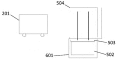
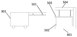
도 6a 내지 도 6d는 본 발명의 실시형태의 측면도로서, 여기에서 외팔보 해결책을 가지는 컨테이너 핸들링 운반체가 측정을 위해서 컨테이너를 테스팅 스테이션 내에 배치한다. 컨테이너 핸들링 운반체는 저장 시스템으로부터 컨테이너를 운반하는 테스팅 스테이션에 접근한다. 컨테이너 핸들링 운반체는 컨테이너를 테스팅 스테이션 내에 배치한다. 컨테이너 핸들링 운반체가 후퇴되어, 테스팅 스테이션이 상단 개구부를 통해서 컨테이너의 내용물에 접근할 수 있게 한다. 테스팅 스테이션은 측정 플랫폼을 컨테이너 상으로 하강시킨다. 측정 플랫폼은 전기 모터에 부착된 라인을 이용하여 하강된다. 이러한 라인은 와이어, 벨트, 체인, 로프 또는 유사물일 수 있다. 측정 플랫폼은 상단 개구부 위에 피팅된다. 플랫폼은 하부측에 부착된 측정 장비를 포함한다. 측정 장비는, 예를 들어, 플랫폼이 컨테이너 상에 배치될 때 컨테이너 내부에 피팅되도록, 하부측에 배치된다. 측정 장비는 온도 센서, 수분 센서, 가스 센서, 및/또는 카메라일 수 있다. 측정 플랫폼에 장착될 수 있는 임의의 다른 종류의 측정 장비가 사용될 수 있다. 수집된 데이터는 중앙 컴퓨터 시스템에 송신될 수 있다. 중앙 컴퓨터 시스템은 데이터를 저장 및 분석할 수 있다. 컨테이너의 내용물의 상태를 계속 추적하기 위해서, 데이터가 컨테이너의 ID와 함께 저장될 수 있다. 컨테이너의 내용물의 상태를 기초로, 중앙 컴퓨터 시스템은 명령어를 컨테이너 핸들링 운반체에 송신하여, 컨테이너를 컨테이너 내의 물품의 상태에 따른 목적지로 운송할 수 있다. 물품이 고객에게 분배할 수 있는 상태에 있는 경우에, 물품을 갖는 컨테이너가, 희망 물품이 추가적인 분배를 위해서 픽킹될 수 있는 스테이션으로 운송되거나, 물품을 갖는 컨테이너가 저장 시스템 내로 역으로 운송될 수 있다. 컨테이너 내의 하나 이상의 물품의 품질이 좋지 못한 경우에, 컨테이너는, 오염 물품을 컨테이너로부터 제거할 수 있는 목적지로 운송될 수 있다. 물품이 제거된 후에, 컨테이너는 저장 시스템으로 다시 운반되거나, 고객에게 추가적으로 분배하기 위해서 물품이 픽킹되는 픽킹 스테이션으로의 추가적인 분배를 위한 포트로 운송된다.6A-6D are side views of an embodiment of the present invention, wherein a container handling vehicle having a cantilever solution places a container into a testing station for measurement; A container handling vehicle approaches a testing station that carries the containers from the storage system. The container handling vehicle places the container in the testing station. The container handling vehicle is retracted, allowing the testing station to access the contents of the container through the top opening. The testing station lowers the measurement platform onto the container. The measuring platform is lowered using a line attached to an electric motor. These lines may be wires, belts, chains, ropes or the like. The measuring platform is fitted over the top opening. The platform includes measuring equipment attached to the underside. The measuring equipment is arranged on the underside, for example, to fit inside the container when the platform is placed on the container. The measuring equipment may be a temperature sensor, a moisture sensor, a gas sensor, and/or a camera. Any other type of measurement equipment that can be mounted on the measurement platform may be used. The collected data may be transmitted to a central computer system. A central computer system may store and analyze the data. To keep track of the state of the container's contents, data may be stored along with the container's ID. Based on the status of the contents of the container, the central computer system can send instructions to the container handling vehicle to transport the container to a destination according to the status of the items in the container. When the goods are in a state ready for dispensing to the customer, the container with the goods may be transported to a station where the desired goods may be picked for further distribution, or the container with the goods may be transported back into the storage system. . If one or more items in the container are of poor quality, the container may be shipped to a destination where the contaminating items may be removed from the container. After the articles are removed, the containers are transported back to the storage system or transported to a port for further distribution to a picking station where the articles are picked for further distribution to the customer.
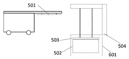
도 7a 내지 도 7d는 본 발명의 실시형태의 측면도로서, 여기에서 컨테이너를 운반하는 전달 운반체가 테스팅 스테이션 내에 배치된다. 전달 운반체가, 전술한 핸들링 운반체와 같은, 컨테이너 위에 배열된 승강 플랫폼을 가지지 않기 때문에, 전달 운반체는 도움이 없이 컨테이너를 테스팅 스테이션 내에 배치할 수 없다. 본 발명의 실시형태에서, 상단부에서 컨테이너를 갖는 전달 운반체는 테스팅 스테이션 내로 피팅된다. 이러한 실시형태에서, 그에 따라, 상단부에서 컨테이너를 갖는 전달 운반체 자체가 테스팅 스테이션으로 이동할 수 있도록, 테스팅 스테이션은 하단부에서 트랙을 갖는다. 테스팅 스테이션은 측정 플랫폼을 컨테이너 상으로 하강시킨다. 측정 플랫폼은 전기 모터에 부착된 와이어, 벨트, 체인, 로프 또는 유사물을 이용하여 하강된다. 측정 플랫폼은 상단 개구부 위에 피팅된다. 플랫폼은 하부측에 부착된 측정 장비를 더 포함한다. 측정 장비는, 플랫폼이 컨테이너 상에 배치될 때 컨테이너 내부에 피팅되도록, 배치된다. 측정 장비는 온도 센서, 수분 센서, 가스 센서, 및/또는 카메라일 수 있다. 측정 플랫폼에 장착될 수 있는 임의의 다른 종류의 측정 장비가 사용될 수 있다. 측정 장비로부터 데이터가 수집된 후에, 데이터는 중앙 컴퓨터 시스템에 송신될 수 있다. 데이터가 수집되었을 때, 상단부에서 컨테이너를 가지는 전달 운반체가 다음 목적지로 운송될 수 있다.7A-7D are side views of an embodiment of the present invention, wherein a delivery vehicle carrying a container is disposed within a testing station; Since the transfer vehicle does not have a lifting platform arranged above the container, such as the handling vehicle described above, the transfer vehicle cannot place the container into the testing station without assistance. In an embodiment of the invention, a delivery vehicle with a container at its upper end is fitted into a testing station. In this embodiment, the testing station has a track at its lower end, so that the delivery vehicle itself with the container at its upper end can move to the testing station. The testing station lowers the measurement platform onto the container. The measuring platform is lowered using a wire, belt, chain, rope or the like attached to an electric motor. The measuring platform is fitted over the top opening. The platform further includes measuring equipment attached to the underside. The measuring equipment is arranged such that it fits inside the container when the platform is placed on the container. The measuring equipment may be a temperature sensor, a moisture sensor, a gas sensor, and/or a camera. Any other type of measurement equipment that can be mounted on the measurement platform may be used. After data is collected from the measurement equipment, the data can be transmitted to a central computer system. When the data has been collected, the delivery vehicle with the container at the top can be transported to the next destination.
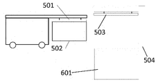
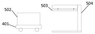
도 8a 내지 도 8d는 본 발명의 대안적인 실시형태의 측면도로서, 여기에서 외팔보 해결책을 가지는 컨테이너 핸들링 운반체가 측정을 위해서 컨테이너를 테스팅 스테이션 내에 배치한다. 컨테이너 핸들링 운반체는 저장 시스템으로부터 컨테이너를 운반하는 테스팅 스테이션에 접근한다. 컨테이너 핸들링 운반체는 컨테이너를 테스팅 스테이션의 기부 상에 배치한다. 컨테이너 핸들링 운반체가 후퇴되어, 테스팅 스테이션이 상단 개구부를 통해서 컨테이너의 내용물에 접근할 수 있게 한다. 테스팅 스테이션은 측정 플랫폼을 컨테이너 상으로 하강시킨다. 측정 플랫폼은 전기 모터에 부착된 와이어, 벨트, 체인, 로프 또는 유사물을 이용하여 하강된다. 측정 플랫폼은 상단 개구부 위에 피팅된다. 플랫폼은 하부측에 부착된 측정 장비를 더 포함한다. 측정 장비는, 플랫폼이 컨테이너 상에 배치될 때 컨테이너 내부에 피팅되도록, 배치된다. 측정 장비는 온도 센서, 수분 센서, 가스 센서, 및/또는 카메라일 수 있다. 측정 플랫폼에 장착될 수 있는 임의의 다른 종류의 측정 장비가 사용될 수 있다. 수집된 데이터는 중앙 컴퓨터 시스템에 송신될 수 있다. 중앙 컴퓨터 시스템은 데이터를 저장 및 분석할 수 있다. 컨테이너의 내용물의 상태를 계속 추적하기 위해서, 데이터가 컨테이너의 ID와 함께 저장될 수 있다. 컨테이너의 내용물의 상태를 기초로, 중앙 컴퓨터 시스템은 명령어를 컨테이너 핸들링 운반체에 송신하여, 컨테이너를 컨테이너 내의 물품의 상태에 따른 목적지로 운송할 수 있다. 물품이 고객에게 분배할 수 있는 상태에 있는 경우에, 물품을 갖는 컨테이너가, 희망 물품이 추가적인 분배를 위해서 픽킹될 수 있는 스테이션으로 운송되거나, 물품을 갖는 컨테이너가 저장 시스템 내로 역으로 운송될 수 있다. 컨테이너 내의 하나 이상의 물품의 품질이 좋지 못한 경우에, 컨테이너는, 오염 물품을 컨테이너로부터 제거할 수 있는 목적지로 운송될 수 있다. 물품이 제거된 후에, 컨테이너는 저장 시스템으로 다시 운반되거나, 고객에게 추가적으로 분배하기 위해서 물품이 픽킹되는 픽킹 스테이션으로의 추가적인 분배를 위한 포트로 운송된다.8A-8D are side views of an alternative embodiment of the present invention, wherein a container handling vehicle having a cantilevered solution places a container into a testing station for measurement; A container handling vehicle approaches a testing station that carries the containers from the storage system. The container handling vehicle places the container on the base of the testing station. The container handling vehicle is retracted, allowing the testing station to access the contents of the container through the top opening. The testing station lowers the measurement platform onto the container. The measuring platform is lowered using a wire, belt, chain, rope or the like attached to an electric motor. The measuring platform is fitted over the top opening. The platform further includes measuring equipment attached to the underside. The measuring equipment is arranged such that it fits inside the container when the platform is placed on the container. The measuring equipment may be a temperature sensor, a moisture sensor, a gas sensor, and/or a camera. Any other type of measurement equipment that can be mounted on the measurement platform may be used. The collected data may be transmitted to a central computer system. A central computer system may store and analyze the data. To keep track of the state of the container's contents, data may be stored along with the container's ID. Based on the status of the contents of the container, the central computer system can send instructions to the container handling vehicle to transport the container to a destination according to the status of the items in the container. When the goods are in a state ready for dispensing to the customer, the container with the goods may be transported to a station where the desired goods may be picked for further distribution, or the container with the goods may be transported back into the storage system. . If one or more items in the container are of poor quality, the container may be shipped to a destination where the contaminating items may be removed from the container. After the articles are removed, the containers are transported back to the storage system or transported to a port for further distribution to a picking station where the articles are picked for further distribution to the customer.
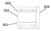
도 9a 내지 도 9c는 본 발명의 대안적인 실시형태의 측면도로서, 여기에서 컨테이너를 운반하는 전달 운반체가 테스팅 스테이션 내에 배치된다. 전달 운반체가 컨테이너를 유지하는 승강 플랫폼을 가지지 않기 때문에, 전달 운반체는 도움이 없이 컨테이너를 테스팅 스테이션 내에 배치할 수 없다. 본 발명의 실시형태에서, 상단부에서 컨테이너를 갖는 전달 운반체는 테스팅 스테이션 내로 피팅된다. 이러한 실시형태에서, 상단부에서 컨테이너를 갖는 전달 운반체 자체가 테스팅 스테이션으로 이동할 수 있도록, 테스팅 스테이션은 테스팅 스테이션의 기부에서 트랙을 갖는다. 테스팅 스테이션은 측정 플랫폼을 컨테이너 상으로 하강시킨다. 측정 플랫폼은 전기 모터에 부착된 와이어, 벨트, 체인, 로프 또는 유사물을 이용하여 하강된다. 측정 플랫폼은 상단 개구부 위에 피팅된다. 플랫폼은 하부측에 부착된 측정 장비를 더 포함한다. 측정 장비는, 플랫폼이 컨테이너 상에 배치될 때 컨테이너 내부에 피팅되도록, 배치된다. 측정 장비는 온도 센서, 수분 센서, 가스 센서, 및/또는 카메라일 수 있다. 측정 플랫폼에 장착될 수 있는 임의의 다른 종류의 측정 장비가 사용될 수 있다. 측정 장비로부터 데이터가 수집된 후에, 데이터는 중앙 컴퓨터 시스템에 송신될 수 있다. 데이터가 수집되었을 때, 상단부에서 컨테이너를 가지는 전달 운반체가 다음 목적지로 운송될 수 있다.9A-9C are side views of an alternative embodiment of the present invention, wherein a delivery vehicle carrying a container is disposed within a testing station; Since the delivery vehicle does not have a lifting platform to hold the container, the delivery vehicle cannot place the container into the testing station without assistance. In an embodiment of the invention, a delivery vehicle with a container at its upper end is fitted into a testing station. In this embodiment, the testing station has a track at the base of the testing station so that the transfer vehicle with the container at the top can move itself to the testing station. The testing station lowers the measurement platform onto the container. The measuring platform is lowered using a wire, belt, chain, rope or the like attached to an electric motor. The measuring platform is fitted over the top opening. The platform further includes measuring equipment attached to the underside. The measuring equipment is arranged such that it fits inside the container when the platform is placed on the container. The measuring equipment may be a temperature sensor, a moisture sensor, a gas sensor, and/or a camera. Any other type of measurement equipment that can be mounted on the measurement platform may be used. After data is collected from the measurement equipment, the data can be transmitted to a central computer system. When the data has been collected, the delivery vehicle with the container at the top can be transported to the next destination.
도 10은 본 발명의 실시형태의 프로세스 내의 단계들을 설명하는 흐름도이다. 컨테이너 핸들링 운반체 또는 전달 운반체가 컨테이너를 저장 시스템으로부터 운송한다. 저장 시스템은 프레임워크 구조물(100)을 갖는 자동화된 저장 및 회수 시스템(1)이고, 직립 부재(102), 수평 부재(103), 및 직립 부재(103)와 수평 부재(102) 사이에서 행으로 배열되는 저장 컬럼(105)을 포함하는 저장 부피를 포함한다. 이러한 저장 컬럼(105) 내에서, 빈으로도 알려져 있는 저장 컨테이너(106)가 서로 상하로 적층되어 적층체(107)를 형성한다. 컨테이너 핸들링 운반체 또는 전달 운반체가 컨테이너를 측정 스테이션으로 운송한다. 컨테이너를 운송하는 운반체에 따라, 컨테이너가 테스팅 스테이션 내에 배치되거나, 상단부에서 컨테이너를 갖는 전달 운반체가 테스팅 스테이션 내에 주차된다. 테스팅 스테이션은 측정 플랫폼을 낮추고, 측정 플랫폼은 컨테이너의 상단부 위에 피팅된다. 측정 플랫폼은 부착 센서를 갖는다. 센서는 온도 센서, 가스 센서, 수분 검출기, 및/또는 카메라일 수 있다. 센서로부터의 데이터가 수집되고 중앙 컴퓨터 시스템으로 송신된다. 중앙 컴퓨터 시스템에서, 수집된 데이터가 컨테이너의 ID와 함께 저장된다. 또한, 데이터가 분석될 수 있고, 분석 결과는 컨테이너 및 그 내용물이 측정 후에 가야 할 곳을 결정하는 기초가 된다. 측정이 수행된 후에, 중앙 컴퓨터 시스템은 명령어를 컨테이너 핸들링 운반체 또는 전달 운반체에 송신하여, 컨테이너를 미리 결정된 목적지로 운송하게 한다. 미리 결정된 목적지는 컨테이너 내의 물품의 품질에 따라 달라진다. 물품이 고객에게 분배할 수 있을 정도로 충분히 양호한 품질을 가지는 경우에, 컨테이너는 포트로 운송되고, 컨테이너는 그러한 포트로부터 추가적인 분배를 위해서 물품이 수집되는 픽킹 스테이션으로 운송되며, 대안적으로, 컨테이너는 저장 그리드 구조물로 다시 운송될 수 있다. 컨테이너 내의 물품이 인간의 소비를 위한 충분한 품질을 가지지 못하는 경우에, 이는, 오염 물품이 컨테이너로부터 픽킹되고 미리 규정된 지시에 따라 폐기되는 목적지로 운송된다.10 is a flowchart illustrating steps within a process of an embodiment of the present invention. A container handling vehicle or delivery vehicle transports the container from the storage system. The storage system is an automated storage and
선행 설명에서, 본 발명에 따른 전달 운반체 및 자동화된 저장 및 회수 시스템의 여러 양태가 예시적인 실시형태를 참조하여 설명되었다. 설명을 위해서, 특정 숫자, 시스템 및 구성이 시스템 및 그 작업의 완전한 이해를 제공하기 위해서 기술되었다. 그러나, 이러한 설명은 제한적인 의미로 해석되는 것으로 의도되지 않는다. 개시된 청구 대상과 관련된 당업자에게 명확한, 예시적인 실시형태의 여러 수정 및 변경뿐만 아니라, 시스템의 다른 실시형태가 본 발명의 범위에 포함되는 것으로 간주된다.In the preceding description, various aspects of a delivery vehicle and an automated storage and retrieval system according to the present invention have been described with reference to exemplary embodiments. For purposes of explanation, specific numbers, systems, and configurations are set forth in order to provide a thorough understanding of the system and its operation. However, this description is not intended to be construed in a limiting sense. Various modifications and variations of the exemplary embodiments, as well as other embodiments of the system, which will be apparent to those skilled in the art with respect to the disclosed subject matter are considered to be included within the scope of the present invention.
종래 기술(도 1 내지 도 10):
100
프레임워크 구조물
102
프레임워크 구조물의 직립 부재
103
프레임워크 구조물의 수평 부재
104
저장 그리드
105
저장 컬럼
106
저장 컨테이너
106'
저장 컨테이너의 특정 위치
107
적층체
108
레일 시스템
110
제1 방향(X)의 평행 레일
110a
제1 방향(X)의 제1 레일
110b
제1 방향(X)의 제2 레일
111
제2 방향(Y)의 평행 레일
111a
제2 방향(Y)의 제1 레일
111b
제2 방향(Y)의 제2 레일
112
접근 개구부
119
제1 포트 컬럼
120
제2 포트 컬럼
201
종래 기술의 저장 컨테이너 운반체
201a
저장 컨테이너 운반체(101)의 운반체 본체
201b
구동 수단/바퀴 배열체, 제1 방향(X)
201c
구동 수단/바퀴 배열체, 제2 방향(Y)
301
종래 기술의 외팔보 저장 컨테이너 운반체
301a
저장 컨테이너 운반체(101)의 운반체 본체
301b
제1 방향(X)의 구동 수단
301c
제2 방향(Y)의 구동 수단
X
제1 방향
Y
제2 방향
Z
제3 방향
401
전달 운반체
501
컨테이너 상승 플랫폼
502
컨테이너
503
측정 플랫폼
504
테스팅 스테이션
601
컨테이너 배치 면적
801
판Prior art (FIGS. 1-10):
100 framework structures
102 Upright members of framework structures
103 Horizontal members of framework structures
104 storage grid
105 storage column
106 storage container
106' specific location in storage container
107 Laminate
108 rail system
110 Parallel rails in the first direction (X)
110a First rail in the first direction (X)
110b second rail in first direction (X)
111 Parallel rail in the second direction (Y)
111a First rail in the second direction (Y)
111b second rail in the second direction (Y)
112 access opening
119 first port column
120 second port column
201 prior art storage container carrier
Carrier body of 201a storage container carrier 101
201b drive means/wheel arrangement, first direction (X)
201c drive means/wheel arrangement, second direction (Y)
301 Prior Art Cantilevered Storage Container Carrier
Carrier body of 301a storage container carrier 101
301b driving means in the first direction (X)
301c Driving means in the second direction (Y)
X first direction
Y second direction
Z third direction
401 transport carrier
501 Container Lifting Platform
502 container
503 Measuring Platform
504 Testing Station
601 Container Placement Area
801 edition
Claims (15)
상기 테스팅 스테이션은 측정 장비를 갖춘 측정 플랫폼(503)이 부착되는 상부 부분(505), 컨테이너(502)를 유지하기 위한 하부 부분(601), 및 상기 상부 부분(505)과 하부 부분(601)을 연결하기 위한 연결 수단을 포함하는, 시스템.According to claim 1,
The testing station comprises an upper part 505 to which a measuring platform 503 equipped with measuring equipment is attached, a lower part 601 for holding the container 502, and the upper part 505 and the lower part 601. A system comprising connecting means for connecting.
상기 하부 부분(601)은 레일의 세트 아래에서 공동을 포함하고, 저장 컨테이너(502)가 상기 공동 내로 하강될 수 있는, 시스템.3. The method of claim 2,
The lower portion (601) comprises a cavity below the set of rails, into which the storage container (502) can be lowered.
상기 하부 부분(601)은 그 위에 트랙의 세트를 갖는 판(801)을 포함하는, 시스템.3. The method of claim 2,
The lower portion (601) comprises a plate (801) having a set of tracks thereon.
상기 테스팅 스테이션은, 저장 컨테이너(502)를 수용하도록 구성된, 상기 상부 부분(505)과 상기 하부 부분(601) 사이의 공간을 포함하는, 시스템.6. The method according to any one of claims 1 to 5,
The testing station comprises a space between the upper portion (505) and the lower portion (601) configured to receive a storage container (502).
상기 테스팅 스테이션은 상기 측정 플랫폼(503)을 상승 및 하강시키도록 구성된 승강 장치를 포함하는, 시스템.5. The method according to any one of claims 2 to 4,
The testing station comprises a lifting device configured to raise and lower the measurement platform (503).
상기 테스팅 스테이션은 상단부에서 저장 컨테이너(502)를 갖는 컨테이너 핸들링 운반체를 수용하도록 구성되는, 시스템.7. The method according to any one of claims 1 to 6,
wherein the testing station is configured to receive a container handling vehicle having a storage container (502) at its upper end.
상기 측정 장비(503)가 전기 모터에 의해서 제어되는 로프, 밴드 또는 와이어에 의해서 상승 및 하강되는, 시스템.8. The method according to any one of claims 1 to 7,
wherein the measuring equipment (503) is raised and lowered by means of a rope, band or wire controlled by an electric motor.
상기 측정 장비가 로봇 아암에 의해서 상승 및 하강되는, 시스템.9. The method according to any one of claims 1 to 8,
wherein the measuring equipment is raised and lowered by a robot arm.
상기 측정 장비가 온도 측정 장비, 수분 검출기, 가스 검출기 및/또는 카메라를 포함하는, 시스템.8. The method according to any one of claims 1 to 7,
The system, wherein the measuring equipment comprises a temperature measuring instrument, a moisture detector, a gas detector and/or a camera.
상기 저장 컨테이너(502) 내에 저장된 물품 상의 곰팡이를 검출하기 위한 UV 광원을 더 포함하는, 시스템.11. The method according to any one of claims 1 to 10,
and a UV light source for detecting mold on articles stored within the storage container (502).
상기 저장 컨테이너(502) 내에 저장된 물품 상의 곰팡이, 바이러스 및 박테리아를 사멸하기 위한 UV-C 광원을 더 포함하는, 시스템.12. The method according to any one of claims 1 to 11,
and a UV-C light source for killing molds, viruses and bacteria on articles stored within the storage container (502).
- 저장 컨테이너(502)를 컨테이너 핸들링 운반체(201, 301, 401)로 상기 테스팅 스테이션(504) 내에 배치하는 단계,
- 상기 테스팅 스테이션(504)에 부착된 측정 장비(503)를 상기 저장 컨테이너(502) 상으로 제공하는 단계,
- 측정 데이터를 수집하기 위해서 측정을 수행하는 단계,
- 상기 측정 데이터를 컴퓨터 시스템에 전송하는 단계,
- 상기 전송된 측정 데이터를 저장하고 상기 측정 데이터의 분석을 수행하는 단계,
- 상기 분석의 결과를 기초로, 상기 컨테이너를 운송하는 곳에 관한 명령어를, 상기 중앙 컴퓨터 시스템으로부터 상기 컨테이너 핸들링 운반체로 전송하는 단계,
- 상기 측정 장비를 상승시키는 단계,
- 컨테이너 핸들링 운반체로 상기 저장 컨테이너(502)를 다음 목적지로 운송하는 단계를 포함하는, 방법.A method for performing measurements in a storage container (502) for storing articles, using a testing station (504), wherein the storage container (502) is a three-dimensional space for storing the storage container (502). stored in an automated storage system comprising a framework structure (100) forming a storage grid structure (104), said grid structure (104) forming a vertical storage column (105), each vertical storage column comprising said Having a horizontal area defined by the size of the access openings 112 of the vertical storage columns 105 , the rail system 108 extends the circumference of each access opening 112 at the upper end of each storage column 105 . Arranged on the framework structure 100 forming, the rail system 108 is used for a container handling vehicle 201 for handling the storage container 502 and transferring it to and from the storage column 105 . Providing possible routes, each vehicle (201, 301, 401) comprising a vehicle controller (230) in communication with a central computer system that controls the operation of the storage system, the method comprising:
- placing a storage container (502) in the testing station (504) with a container handling vehicle (201, 301, 401);
- providing the measuring equipment (503) attached to the testing station (504) onto the storage container (502);
- performing measurements to collect measurement data;
- transmitting said measurement data to a computer system;
- storing the transmitted measurement data and performing an analysis of the measurement data;
- sending, on the basis of the result of the analysis, instructions on where to transport the container from the central computer system to the container handling vehicle;
- raising the measuring device;
- transporting the storage container (502) to a next destination in a container handling vehicle.
상기 저장 컨테이너(502) 내의 온도, 수분 및/또는 가스 레벨의 측정을 수행하는 및/또는 상기 물품의 시각적 검사를 위해서 카메라를 이용하는, 방법.14. The method of claim 13,
and/or using a camera for visual inspection of the article and/or performing measurements of temperature, moisture and/or gas levels within the storage container (502).
상기 가스 검출기가 상기 저장 컨테이너(502) 내로 하강되는, 방법.15. The method of claim 14,
wherein the gas detector is lowered into the storage container (502).
Applications Claiming Priority (3)
| Application Number | Priority Date | Filing Date | Title |
|---|---|---|---|
| NO20200120 | 2020-01-31 | ||
| NO20200120A NO345921B1 (en) | 2020-01-31 | 2020-01-31 | System and method for performing measurements in storage containers |
| PCT/EP2021/051779 WO2021151906A1 (en) | 2020-01-31 | 2021-01-26 | Sensor testing station |
Publications (1)
| Publication Number | Publication Date |
|---|---|
| KR20220132616A true KR20220132616A (en) | 2022-09-30 |
Family
ID=74347085
Family Applications (1)
| Application Number | Title | Priority Date | Filing Date |
|---|---|---|---|
| KR1020227029576A KR20220132616A (en) | 2020-01-31 | 2021-01-26 | sensor testing station |
Country Status (8)
| Country | Link |
|---|---|
| US (1) | US20230056161A1 (en) |
| EP (1) | EP4097029B1 (en) |
| JP (1) | JP2023512240A (en) |
| KR (1) | KR20220132616A (en) |
| CN (1) | CN115038655A (en) |
| CA (1) | CA3164334A1 (en) |
| NO (1) | NO345921B1 (en) |
| WO (1) | WO2021151906A1 (en) |
Family Cites Families (13)
| Publication number | Priority date | Publication date | Assignee | Title |
|---|---|---|---|---|
| CA2889597A1 (en) * | 2012-10-26 | 2014-05-01 | GreenTech Agro LLC | Self-sustaining artificially controllable environment within a storage container or other enclosed space |
| NO334806B1 (en) | 2012-11-13 | 2014-06-02 | Jakob Hatteland Logistics As | storage System |
| NO335839B1 (en) | 2012-12-10 | 2015-03-02 | Jakob Hatteland Logistics As | Robot for transporting storage containers |
| NO337544B1 (en) | 2014-06-19 | 2016-05-02 | Jakob Hatteland Logistics As | Remote controlled vehicle assembly to pick up storage containers from a storage system |
| CA2978163C (en) * | 2015-04-15 | 2024-01-09 | Ocado Innovation Limited | Storage system and methods |
| EP3326452B1 (en) * | 2016-11-24 | 2020-06-10 | Heliospectra AB | Cultivation storage system |
| NO20170216A1 (en) | 2017-02-13 | 2018-08-14 | Autostore Tech As | Rail arrangement for wheeled vehicles in a storage system |
| CN109720830B (en) * | 2017-10-30 | 2024-02-20 | 杭州海康机器人股份有限公司 | Loading device of automatic guiding carrier, control method of loading device and loading control system |
| GB201720633D0 (en) * | 2017-12-11 | 2018-01-24 | Ocado Innovation Ltd | Robotic parking device and handling method |
| CN207844078U (en) * | 2018-02-08 | 2018-09-11 | 深圳捷佳德现金自动化处理设备有限公司 | A kind of high density intelligent warehousing system using robot |
| NO344302B1 (en) * | 2018-04-25 | 2019-10-28 | Autostore Tech As | Automated storage and retrieval system comprising a relay module and a method of operating such a system |
| GB201809020D0 (en) * | 2018-06-01 | 2018-07-18 | Ocado Innovation Ltd | Control device and method for item verification |
| CN110304388B (en) * | 2019-07-10 | 2021-03-02 | 四川易景智能终端有限公司 | Intelligent scheduling system for unmanned warehouse |
-
2020
- 2020-01-31 NO NO20200120A patent/NO345921B1/en unknown
-
2021
- 2021-01-26 CA CA3164334A patent/CA3164334A1/en active Pending
- 2021-01-26 KR KR1020227029576A patent/KR20220132616A/en unknown
- 2021-01-26 US US17/796,020 patent/US20230056161A1/en active Pending
- 2021-01-26 EP EP21702233.4A patent/EP4097029B1/en active Active
- 2021-01-26 JP JP2022546003A patent/JP2023512240A/en active Pending
- 2021-01-26 WO PCT/EP2021/051779 patent/WO2021151906A1/en active Search and Examination
- 2021-01-26 CN CN202180012189.4A patent/CN115038655A/en active Pending
Also Published As
| Publication number | Publication date |
|---|---|
| NO20200120A1 (en) | 2021-08-02 |
| EP4097029A1 (en) | 2022-12-07 |
| CN115038655A (en) | 2022-09-09 |
| WO2021151906A1 (en) | 2021-08-05 |
| US20230056161A1 (en) | 2023-02-23 |
| JP2023512240A (en) | 2023-03-24 |
| EP4097029B1 (en) | 2024-04-24 |
| CA3164334A1 (en) | 2021-08-05 |
| NO345921B1 (en) | 2021-10-25 |
Similar Documents
| Publication | Publication Date | Title |
|---|---|---|
| US20230053090A1 (en) | System and method for performing measurements in storage containers | |
| US20230065714A1 (en) | Conveyor system | |
| CN113950453B (en) | Storage system | |
| JP2022545665A (en) | Delivery system, automated warehouse system, and method for transporting containers | |
| KR20220132616A (en) | sensor testing station | |
| KR20220131997A (en) | Systems and methods for monitoring atmospheric conditions in automated storage and retrieval systems | |
| KR20230048123A (en) | Systems and methods for detecting anomalies in tracks of three-dimensional storage systems | |
| TW202334012A (en) | A vehicle-portable grid assessment device | |
| US20230131214A1 (en) | Robotic consolidation station and storage system | |
| NO346957B1 (en) | A gripper assembly | |
| JP3101850B2 (en) | Transport control device for nuclear fuel pellet inspection products | |
| WO2023061835A1 (en) | A delivery port for delivery of goods contained in goods holders | |
| CN117794834A (en) | Automated warehouse systems, assemblies, devices, and methods for assembling hybrid pallets and facilitating order picking |