EP4097029B1 - Sensor testing station - Google Patents
Sensor testing station Download PDFInfo
- Publication number
- EP4097029B1 EP4097029B1 EP21702233.4A EP21702233A EP4097029B1 EP 4097029 B1 EP4097029 B1 EP 4097029B1 EP 21702233 A EP21702233 A EP 21702233A EP 4097029 B1 EP4097029 B1 EP 4097029B1
- Authority
- EP
- European Patent Office
- Prior art keywords
- storage
- container
- testing station
- items
- measuring equipment
- Prior art date
- Legal status (The legal status is an assumption and is not a legal conclusion. Google has not performed a legal analysis and makes no representation as to the accuracy of the status listed.)
- Active
Links
- 238000012360 testing method Methods 0.000 title claims description 56
- 238000003860 storage Methods 0.000 claims description 179
- 238000005259 measurement Methods 0.000 claims description 25
- 238000000034 method Methods 0.000 claims description 11
- 238000004458 analytical method Methods 0.000 claims description 7
- 241000894006 Bacteria Species 0.000 claims description 4
- 238000009529 body temperature measurement Methods 0.000 claims description 2
- 238000011179 visual inspection Methods 0.000 claims description 2
- 241000700605 Viruses Species 0.000 claims 1
- 238000009826 distribution Methods 0.000 description 14
- 230000032258 transport Effects 0.000 description 14
- 235000013305 food Nutrition 0.000 description 9
- 239000007789 gas Substances 0.000 description 9
- CURLTUGMZLYLDI-UHFFFAOYSA-N Carbon dioxide Chemical compound O=C=O CURLTUGMZLYLDI-UHFFFAOYSA-N 0.000 description 6
- 210000004027 cell Anatomy 0.000 description 6
- 230000001419 dependent effect Effects 0.000 description 6
- 238000012546 transfer Methods 0.000 description 4
- RWSOTUBLDIXVET-UHFFFAOYSA-N Dihydrogen sulfide Chemical compound S RWSOTUBLDIXVET-UHFFFAOYSA-N 0.000 description 3
- 229910002092 carbon dioxide Inorganic materials 0.000 description 3
- 239000001569 carbon dioxide Substances 0.000 description 3
- 238000006073 displacement reaction Methods 0.000 description 3
- 238000012544 monitoring process Methods 0.000 description 3
- 239000000523 sample Substances 0.000 description 3
- 238000013459 approach Methods 0.000 description 2
- VNWKTOKETHGBQD-UHFFFAOYSA-N methane Chemical compound C VNWKTOKETHGBQD-UHFFFAOYSA-N 0.000 description 2
- 210000000352 storage cell Anatomy 0.000 description 2
- 240000005561 Musa balbisiana Species 0.000 description 1
- 229910052782 aluminium Inorganic materials 0.000 description 1
- XAGFODPZIPBFFR-UHFFFAOYSA-N aluminium Chemical compound [Al] XAGFODPZIPBFFR-UHFFFAOYSA-N 0.000 description 1
- 235000021015 bananas Nutrition 0.000 description 1
- 238000010276 construction Methods 0.000 description 1
- 238000002845 discoloration Methods 0.000 description 1
- 238000005286 illumination Methods 0.000 description 1
- 239000007788 liquid Substances 0.000 description 1
- 238000004519 manufacturing process Methods 0.000 description 1
- 229910052751 metal Inorganic materials 0.000 description 1
- 239000002184 metal Substances 0.000 description 1
- 238000012986 modification Methods 0.000 description 1
- 230000004048 modification Effects 0.000 description 1
- 230000003245 working effect Effects 0.000 description 1
Images


Classifications
-
- B—PERFORMING OPERATIONS; TRANSPORTING
- B65—CONVEYING; PACKING; STORING; HANDLING THIN OR FILAMENTARY MATERIAL
- B65G—TRANSPORT OR STORAGE DEVICES, e.g. CONVEYORS FOR LOADING OR TIPPING, SHOP CONVEYOR SYSTEMS OR PNEUMATIC TUBE CONVEYORS
- B65G1/00—Storing articles, individually or in orderly arrangement, in warehouses or magazines
- B65G1/02—Storage devices
- B65G1/04—Storage devices mechanical
- B65G1/0464—Storage devices mechanical with access from above
-
- G—PHYSICS
- G01—MEASURING; TESTING
- G01D—MEASURING NOT SPECIALLY ADAPTED FOR A SPECIFIC VARIABLE; ARRANGEMENTS FOR MEASURING TWO OR MORE VARIABLES NOT COVERED IN A SINGLE OTHER SUBCLASS; TARIFF METERING APPARATUS; MEASURING OR TESTING NOT OTHERWISE PROVIDED FOR
- G01D21/00—Measuring or testing not otherwise provided for
- G01D21/02—Measuring two or more variables by means not covered by a single other subclass
-
- B—PERFORMING OPERATIONS; TRANSPORTING
- B65—CONVEYING; PACKING; STORING; HANDLING THIN OR FILAMENTARY MATERIAL
- B65G—TRANSPORT OR STORAGE DEVICES, e.g. CONVEYORS FOR LOADING OR TIPPING, SHOP CONVEYOR SYSTEMS OR PNEUMATIC TUBE CONVEYORS
- B65G1/00—Storing articles, individually or in orderly arrangement, in warehouses or magazines
- B65G1/02—Storage devices
- B65G1/04—Storage devices mechanical
-
- A—HUMAN NECESSITIES
- A61—MEDICAL OR VETERINARY SCIENCE; HYGIENE
- A61L—METHODS OR APPARATUS FOR STERILISING MATERIALS OR OBJECTS IN GENERAL; DISINFECTION, STERILISATION OR DEODORISATION OF AIR; CHEMICAL ASPECTS OF BANDAGES, DRESSINGS, ABSORBENT PADS OR SURGICAL ARTICLES; MATERIALS FOR BANDAGES, DRESSINGS, ABSORBENT PADS OR SURGICAL ARTICLES
- A61L2/00—Methods or apparatus for disinfecting or sterilising materials or objects other than foodstuffs or contact lenses; Accessories therefor
- A61L2/02—Methods or apparatus for disinfecting or sterilising materials or objects other than foodstuffs or contact lenses; Accessories therefor using physical phenomena
- A61L2/08—Radiation
- A61L2/10—Ultra-violet radiation
-
- A—HUMAN NECESSITIES
- A61—MEDICAL OR VETERINARY SCIENCE; HYGIENE
- A61L—METHODS OR APPARATUS FOR STERILISING MATERIALS OR OBJECTS IN GENERAL; DISINFECTION, STERILISATION OR DEODORISATION OF AIR; CHEMICAL ASPECTS OF BANDAGES, DRESSINGS, ABSORBENT PADS OR SURGICAL ARTICLES; MATERIALS FOR BANDAGES, DRESSINGS, ABSORBENT PADS OR SURGICAL ARTICLES
- A61L2/00—Methods or apparatus for disinfecting or sterilising materials or objects other than foodstuffs or contact lenses; Accessories therefor
- A61L2/24—Apparatus using programmed or automatic operation
-
- B—PERFORMING OPERATIONS; TRANSPORTING
- B65—CONVEYING; PACKING; STORING; HANDLING THIN OR FILAMENTARY MATERIAL
- B65G—TRANSPORT OR STORAGE DEVICES, e.g. CONVEYORS FOR LOADING OR TIPPING, SHOP CONVEYOR SYSTEMS OR PNEUMATIC TUBE CONVEYORS
- B65G1/00—Storing articles, individually or in orderly arrangement, in warehouses or magazines
- B65G1/02—Storage devices
- B65G1/04—Storage devices mechanical
- B65G1/0478—Storage devices mechanical for matrix-arrangements
-
- B—PERFORMING OPERATIONS; TRANSPORTING
- B65—CONVEYING; PACKING; STORING; HANDLING THIN OR FILAMENTARY MATERIAL
- B65G—TRANSPORT OR STORAGE DEVICES, e.g. CONVEYORS FOR LOADING OR TIPPING, SHOP CONVEYOR SYSTEMS OR PNEUMATIC TUBE CONVEYORS
- B65G1/00—Storing articles, individually or in orderly arrangement, in warehouses or magazines
- B65G1/02—Storage devices
- B65G1/04—Storage devices mechanical
- B65G1/06—Storage devices mechanical with means for presenting articles for removal at predetermined position or level
- B65G1/065—Storage devices mechanical with means for presenting articles for removal at predetermined position or level with self propelled cars
-
- B—PERFORMING OPERATIONS; TRANSPORTING
- B65—CONVEYING; PACKING; STORING; HANDLING THIN OR FILAMENTARY MATERIAL
- B65G—TRANSPORT OR STORAGE DEVICES, e.g. CONVEYORS FOR LOADING OR TIPPING, SHOP CONVEYOR SYSTEMS OR PNEUMATIC TUBE CONVEYORS
- B65G1/00—Storing articles, individually or in orderly arrangement, in warehouses or magazines
- B65G1/02—Storage devices
- B65G1/04—Storage devices mechanical
- B65G1/137—Storage devices mechanical with arrangements or automatic control means for selecting which articles are to be removed
- B65G1/1373—Storage devices mechanical with arrangements or automatic control means for selecting which articles are to be removed for fulfilling orders in warehouses
- B65G1/1378—Storage devices mechanical with arrangements or automatic control means for selecting which articles are to be removed for fulfilling orders in warehouses the orders being assembled on fixed commissioning areas remote from the storage areas
-
- A—HUMAN NECESSITIES
- A61—MEDICAL OR VETERINARY SCIENCE; HYGIENE
- A61L—METHODS OR APPARATUS FOR STERILISING MATERIALS OR OBJECTS IN GENERAL; DISINFECTION, STERILISATION OR DEODORISATION OF AIR; CHEMICAL ASPECTS OF BANDAGES, DRESSINGS, ABSORBENT PADS OR SURGICAL ARTICLES; MATERIALS FOR BANDAGES, DRESSINGS, ABSORBENT PADS OR SURGICAL ARTICLES
- A61L2202/00—Aspects relating to methods or apparatus for disinfecting or sterilising materials or objects
- A61L2202/10—Apparatus features
- A61L2202/11—Apparatus for generating biocidal substances, e.g. vaporisers, UV lamps
-
- A—HUMAN NECESSITIES
- A61—MEDICAL OR VETERINARY SCIENCE; HYGIENE
- A61L—METHODS OR APPARATUS FOR STERILISING MATERIALS OR OBJECTS IN GENERAL; DISINFECTION, STERILISATION OR DEODORISATION OF AIR; CHEMICAL ASPECTS OF BANDAGES, DRESSINGS, ABSORBENT PADS OR SURGICAL ARTICLES; MATERIALS FOR BANDAGES, DRESSINGS, ABSORBENT PADS OR SURGICAL ARTICLES
- A61L2202/00—Aspects relating to methods or apparatus for disinfecting or sterilising materials or objects
- A61L2202/10—Apparatus features
- A61L2202/14—Means for controlling sterilisation processes, data processing, presentation and storage means, e.g. sensors, controllers, programs
-
- B—PERFORMING OPERATIONS; TRANSPORTING
- B65—CONVEYING; PACKING; STORING; HANDLING THIN OR FILAMENTARY MATERIAL
- B65G—TRANSPORT OR STORAGE DEVICES, e.g. CONVEYORS FOR LOADING OR TIPPING, SHOP CONVEYOR SYSTEMS OR PNEUMATIC TUBE CONVEYORS
- B65G2201/00—Indexing codes relating to handling devices, e.g. conveyors, characterised by the type of product or load being conveyed or handled
- B65G2201/02—Articles
- B65G2201/0235—Containers
- B65G2201/0258—Trays, totes or bins
-
- B—PERFORMING OPERATIONS; TRANSPORTING
- B65—CONVEYING; PACKING; STORING; HANDLING THIN OR FILAMENTARY MATERIAL
- B65G—TRANSPORT OR STORAGE DEVICES, e.g. CONVEYORS FOR LOADING OR TIPPING, SHOP CONVEYOR SYSTEMS OR PNEUMATIC TUBE CONVEYORS
- B65G2203/00—Indexing code relating to control or detection of the articles or the load carriers during conveying
- B65G2203/04—Detection means
- B65G2203/041—Camera
-
- B—PERFORMING OPERATIONS; TRANSPORTING
- B65—CONVEYING; PACKING; STORING; HANDLING THIN OR FILAMENTARY MATERIAL
- B65G—TRANSPORT OR STORAGE DEVICES, e.g. CONVEYORS FOR LOADING OR TIPPING, SHOP CONVEYOR SYSTEMS OR PNEUMATIC TUBE CONVEYORS
- B65G2203/00—Indexing code relating to control or detection of the articles or the load carriers during conveying
- B65G2203/04—Detection means
- B65G2203/042—Sensors
- B65G2203/045—Thermic
-
- B—PERFORMING OPERATIONS; TRANSPORTING
- B65—CONVEYING; PACKING; STORING; HANDLING THIN OR FILAMENTARY MATERIAL
- B65G—TRANSPORT OR STORAGE DEVICES, e.g. CONVEYORS FOR LOADING OR TIPPING, SHOP CONVEYOR SYSTEMS OR PNEUMATIC TUBE CONVEYORS
- B65G2207/00—Indexing codes relating to constructional details, configuration and additional features of a handling device, e.g. Conveyors
- B65G2207/30—Modular constructions
Definitions
- the present invention relates to an automated storage and retrieval system for storage and retrieval of containers, in particular to a system and a method for performing measurements in a container when placed in a testing station comprising measuring equipment.
- EP3326452 A1 describes an illuminated cultivation storage system and a method for cultivating crops in an illuminated cultivation storage system.
- the system comprises a three-dimensional framework structure forming a grid of vertical and horizontal storage tunnels, a plurality of storage containers for holding growing crops.
- the storage containers being configured to be introduced into the framework structure.
- the system further has a plurality of lighting device, a transport system, and an illumination controller. Further, the interior of the framework structure exhibits distinguishable climate zones, each climate zone having a set of growth parameters including temperature.
- the system further comprises a growth monitoring station which includes sensors for determining a current growth status of crops and a growth controller connected to the transport system and being configured to operate the transport system in order to return storage containers to a designated climate zone based on the determined growth status.
- Fig. 1 of the present disclosure discloses a typical prior art automated storage and retrieval system 1 with a framework structure 100 and Fig. 2 and 3 discloses two different prior art container handling vehicles 201,301 suitable for operating on such a system 1.
- the framework structure 100 comprises upright members 102, horizontal members 103 and a storage volume comprising storage columns 105 arranged in rows between the upright members 102 and the horizontal members 103.
- storage columns 105 storage containers 106, also known as bins, are stacked one on top of one another to form stacks 107.
- the members 102, 103 may typically be made of metal, e.g. extruded aluminum profiles.
- the framework structure 100 of the automated storage and retrieval system 1 comprises a rail system 108 arranged across the top of framework structure 100, on which rail system 108 a plurality of container handling vehicles 201,301 are operated to raise storage containers 106 from, and lower storage containers 106 into, the storage columns 105, and also to transport the storage containers 106 above the storage columns 105.
- the rail system 108 comprises a first set of parallel rails 110 arranged to guide movement of the container handling vehicles 201,301 in a first direction X across the top of the frame structure 100, and a second set of parallel rails 111 arranged perpendicular to the first set of rails 110 to guide movement of the container handling vehicles 201,301 in a second direction Y which is perpendicular to the first direction X.
- Containers 106 stored in the columns 105 are accessed by the container handling vehicles through access openings 112 in the rail system 108.
- the container handling vehicles 201,301 can move laterally above the storage columns 105, i.e. in a plane which is parallel to the horizontal X-Y plane.
- the upright members 102 of the framework structure 100 may be used to guide the storage containers during raising of the containers out from and lowering of the containers into the columns 105.
- the stacks 107 of containers 106 are typically self-supportive.
- Each prior art container handling vehicle 201,301 comprises a vehicle body 201a,301a, and first and second sets of wheels 201b,301b,201c,301c which enable the lateral movement of the container handling vehicles 201,301 in the X direction and in the Y direction, respectively.
- first and second sets of wheels 201b,301b,201c,301c which enable the lateral movement of the container handling vehicles 201,301 in the X direction and in the Y direction, respectively.
- the first set of wheels 201b,301b is arranged to engage with two adjacent rails of the first set 110 of rails
- the second set of wheels 201c,301c is arranged to engage with two adjacent rails of the second set 111 of rails.
- At least one of set wheels 201b,301b,201c,301c can be lifted and lowered, so that the first set of wheels 201b,301b and/or the second set of wheels 201c,301c can be engaged with the respective set of rails 110, 111 at any one time.
- Each prior art container handling vehicle 201,301 also comprises a lifting device (not shown) for vertical transportation of storage containers 106, e.g. raising a storage container 106 from, and lowering a storage container 106 into, a storage column 105.
- the lifting device comprises one or more gripping / engaging devices which are adapted to engage a storage container 106, and which gripping / engaging devices can be lowered from the vehicle 201,301 so that the position of the gripping / engaging devices with respect to the vehicle 201,301 can be adjusted in a third direction Z which is orthogonal the first direction X and the second direction Y.
- Parts of the gripping device of the container handling vehicle 301 is shown in in fig. 3 and is indicated with reference number 304.
- the gripping device of the container handling device 201 is located within the vehicle body 301a in Fig. 2 .
- the storage volume of the framework structure 100 has often been referred to as a grid 104, where the possible storage positions within this grid is referred to as a storage cell.
- Each storage column may be identified by a position in an X- and Y-direction, while each storage cell may be identified by a container number in the X-, Y and Z-direction.
- Each prior art container handling vehicle 201,301 comprises a storage compartment or space for receiving and stowing a storage container 106 when transporting the storage container 106 across the rail system 108.
- the storage space may comprise a cavity arranged centrally within the vehicle body 201a as shown in Fig. 2 and as described in e.g. WO2015/193278A1 .
- FIG. 3 shows an alternative configuration of a container handling vehicle 301 with a cantilever construction. Such a vehicle is described in detail in e.g. NO317366 .
- the central cavity container handling vehicles 201 shown in Fig. 2 may have a footprint that covers an area with dimensions in the X and Y directions which is generally equal to the lateral extent of a storage column 105, e.g. as is described in WO2015/193278A1 .
- 'lateral' used herein may mean 'horizontal'.
- the central cavity container handling vehicles 101 may have a footprint which is larger than the lateral area defined by a storage column 105, e.g. as is disclosed in WO2014/090684A1 .
- the rail system 108 typically comprises rails with grooves into which the wheels of the vehicles are inserted.
- the rails may comprise upwardly protruding elements, where the wheels of the vehicles comprise flanges to prevent derailing. These grooves and upwardly protruding elements are collectively known as tracks.
- Each rail may comprise one track, or each rail may comprise two parallel tracks.
- WO2018146304 illustrates a typical configuration of rail system 108 comprising rails and parallel tracks in both X and Y directions.
- columns 105 In the framework structure 100, a majority of the columns 105 are storage columns 105, i.e. columns 105 where storage containers 106 are stored in stacks 107. However, some columns 105 may have other purposes.
- columns 119 and 120 are such special-purpose columns used by the container handling vehicles 201,301 to drop off and/or pick up storage containers 106 so that they can be transported to an access station (not shown) where the storage containers 106 can be accessed from outside of the framework structure 100 or transferred out of or into the framework structure 100.
- such a location is normally referred to as a 'port' and the column in which the port is located may be referred to as a 'port column' 119,120.
- the transportation to the access station may be in any direction, that is horizontal, tilted and/or vertical.
- the storage containers 106 may be placed in a random or dedicated column 105 within the framework structure 100, then picked up by any container handling vehicle and transported to a port column 119,120 for further transportation to an access station.
- 'tilted' means transportation of storage containers 106 having a general transportation orientation somewhere between horizontal and vertical.
- the first port column 119 may for example be a dedicated drop-off port column where the container handling vehicles 201,301 can drop off storage containers 106 to be transported to an access or a transfer station
- the second port column 120 may be a dedicated pick-up port column where the container handling vehicles 201,301 can pick up storage containers 106 that have been transported from an access or a transfer station.
- the access station may typically be a picking or a stocking station where product items are removed from or positioned into the storage containers 106.
- the storage containers 106 are normally not removed from the automated storage and retrieval system 1, but are returned into the framework structure 100 again once accessed.
- a port can also be used for transferring storage containers to another storage facility (e.g. to another framework structure or to another automated storage and retrieval system), to a transport vehicle (e.g. a train or a lorry), or to a production facility.
- a conveyor system comprising conveyors is normally employed to transport the storage containers between the port columns 119,120 and the access station.
- the conveyor system may comprise a lift device with a vertical component for transporting the storage containers 106 vertically between the port column 119,120 and the access station.
- the conveyor system may be arranged to transfer storage containers 106 between different framework structures, e.g. as is described in WO2014/075937A1
- one of the container handling vehicles 201,301 is instructed to retrieve the target storage container 106 from its position and transport it to the drop-off port column 119.
- This operation involves moving the container handling vehicle 201,301 to a location above the storage column 105 in which the target storage container 106 is positioned, retrieving the storage container 106 from the storage column 105 using the container handling vehicle's 201,301 lifting device (not shown), and transporting the storage container 106 to the drop-off port column 119. If the target storage container 106 is located deep within a stack 107, i.e.
- the operation also involves temporarily moving the above-positioned storage containers prior to lifting the target storage container 106 from the storage column 105.
- This step which is sometimes referred to as "digging" within the art, may be performed with the same container handling vehicle that is subsequently used for transporting the target storage container to the drop-off port column 119, or with one or a plurality of other cooperating container handling vehicles.
- the automated storage and retrieval system 1 may have container handling vehicles specifically dedicated to the task of temporarily removing storage containers from a storage column 105. Once the target storage container 106 has been removed from the storage column 105, the temporarily removed storage containers can be repositioned into the original storage column 105. However, the removed storage containers may alternatively be relocated to other storage columns.
- one of the container handling vehicles 201,301 When a storage container 106 is to be stored in one of the columns 105, one of the container handling vehicles 201,301 is instructed to pick up the storage container 106 from the pick-up port column 120 and transport it to a location above the storage column 105 where it is to be stored. After any storage containers positioned at or above the target position within the storage column stack 107 have been removed, the container handling vehicle 201,301 positions the storage container 106 at the desired position. The removed storage containers may then be lowered back into the storage column 105, or relocated to other storage columns.
- the automated storage and retrieval system 1 For monitoring and controlling the automated storage and retrieval system 1, e.g. monitoring and controlling the location of respective storage containers 106 within the framework structure 100, the content of each storage container 106; and the movement of the container handling vehicles 201,301 so that a desired storage container 106 can be delivered to the desired location at the desired time without the container handling vehicles 201,301 colliding with each other, the automated storage and retrieval system 1 comprises a control system 500 which typically is computerized and which typically comprises a database for keeping track of the storage containers 106.
- FIG. 4 describes a delivery vehicle.
- the delivery vehicles comprise a base with the same setup of wheels as on the container handling vehicles.
- the wheel base unit features a wheel arrangement having a first set of wheels for movement in a first direction upon a rail grid (i.e. any of the top rail grid and the transfer rail grid) and a second set of wheels for movement in a second direction perpendicular to the first direction.
- Each set of wheels comprises two pairs of wheels arranged on opposite sides of the wheel base unit.
- one of the sets of wheels is connected to a wheel displacement assembly.
- the wheel displacement assembly is able to lift and lower the connected set of wheels relative to the other set of wheels such that only the set of wheels travelling in a desired direction is in contact with the rail grid.
- the wheel displacement assembly is driven by an electric motor. Further, two electric motors, powered by a rechargeable battery, are connected to the set of wheels to move the wheel base unit in the desired direction.
- the horizontal periphery of the wheel base unit is dimensioned to fit within the horizontal area defined by a grid cell of the rail grid such that two-wheel base units may pass each other on any adjacent grid cells of the rail grid.
- the wheel base unit may have a footprint, i.e. an extent in the X and Y directions, which is generally equal to the horizontal area of a grid cell, i.e. the extent of a grid cell in the X and Y directions, e.g. as is described in WO2015/193278A1 .
- the invention is related to a system for performing measurements in storage containers for storing items
- the storage containers are stored in an automated storage system
- an automated storage system comprising a framework structure forming a three-dimensional storage grid structure for storing the storage containers, where the grid structure forms vertical storage columns each having a horizontal area defined by the size of an access opening of the vertical storage columns and where a rail system is arranged on the framework structure defining the circumference of each access opening on top of each storage column, the rail system providing available routes for container handling vehicles handling and transferring the storage containers to and from the storage columns, and wherein said system is wherein the system further comprises a testing station, accessible to a container handling vehicle via the rail system, with measuring equipment for measuring atmospheric conditions and for performing measurements in said storage container and where the testing station is configured to communicate measurement data to a computer system
- testing station may comprise an upper part to which the measuring platform is attached, a lower part for receiving the container and a part connecting the upper and the lower part. Also the testing station may have a space for accommodating a container between the upper and the lower part, and the testing station may be adapted to raise and lower the measuring platform.
- the testing station may be adapted to accommodate a container handling vehicle with a container on top.
- the measuring platform may be raised and lowered by a rope, band or wire controlled by an electric motor, or the measuring platform may be raised and lowered by a robotic arm, and the measuring platform comprises temperature measurement equipment, moisture detectors, gas detectors and cameras.
- the invention is directed to a method according to claim 11 of performing measurements in a container for storing in an automated storage system comprising a three-dimensional grid (4) of an underlying storage system (1), at least one container handling vehicle for transporting containers, ports for picking items for further distribution, a central computer system for controlling the operation of the storage system, and wherein said method comprises the steps of: placing a container in a testing station by means of a container handling vehicle, lowering a measuring platform attached to the testing station onto the container, performing measurements, transmitting the measurements to the central computer system, performing an analysis based upon the measurements, transmitting instructions based on the analysis to a container handling vehicle, raising the measuring platform, transporting the container to another destination by means of a container handling vehicle. Performing measurements of temperature, moisture and gas level in the container and by using cameras for visual inspection of the items.
- the framework structure 100 of the automated storage and retrieval system 1 is constructed in accordance with the prior art framework structure 100 described above in connection with Figs. 1-3 , i.e. a number of upright members 102 and a number of horizontal members 103, which are supported by the upright members 102, and further that the framework structure 100 comprises a first, upper rail system 108 in the X direction and Y direction.
- the framework structure 100 further comprises storage compartments in the form of storage columns 105 provided between the members 102, 103, where storage containers 106 are stackable in stacks 107 within the storage columns 105.
- the framework structure 100 can be of any size. In particular it is understood that the framework structure can be considerably wider and/or longer and/or deeper than disclosed in Fig. 1 .
- the framework structure 100 may have a horizontal extent of more than 700x700 columns and a storage depth of more than twelve containers.
- the testing station is comprised of a top portion.
- This top portion houses the measuring platform.
- the measuring platform comprises at least one sensor.
- the at least one sensor is used to measure a at least one atmospheric condition in a storage container.
- One such atmospheric condition might be the temperature in the container, further the sensor can be used to detect the presence of gasses that is released during rotting of food.
- One such gas can be methane.
- Other gasses that are released during decay of food is carbon dioxide and hydrogen sulphide. In the case of carbon dioxide and hydrogen sulphide they are heavier than air and will therefore collect at the bottom of the container.
- the sensors for sensing carbon dioxide and hydrogen sulphide can therefore be attached to a probe that is lowered into the container.
- detectors to detect moisture. The presense of moisture is due to the fact that during rotting of food the cells of the food is broken down and the liquid in the cells leaks out.
- a further type of measuring equipment can be a camera. The camera can take pictures into the container, i.e., of the contents, in order to detect if there is any sign of rotting food.
- the camera can be an ordinary camera that takes colour images in order to detect if there is marks on the food, like e.g., brown spots on bananas, or discoloration on the surface due to milldue.
- a camera that has ultraviolet light in order to detect mold.
- the measuring platform can have a UV light source that can be used to both detect rotting food and to kill bacteria and mold on the food and in the container.
- the difference between using the UV light source to detect decay and to kill bacteria and mold is the wavelength of the light and the power of the light souce.
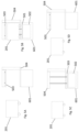
- Fig. 5A-D is a side view of an embodiment of the present invention wherein a container handling vehicle with a central cavity places a container in a testing station for measurements.
- the container handling vehicle with a container in its central cavity moves into the testing station.
- the container is lowered down into a cavity underneath the container handling vehicle.
- the container handling vehicle moves away.
- the measuring equipment is lowered down on a measuring platform.
- the testing station lowers a measuring platform onto the container.
- the measuring platform is lowered using lines attached to an electric motor. These lines can be wire, belts, chains, rope or similar.
- the measuring platform fits over the top opening.
- the platform further comprises measuring equipment attached to the underside.
- the measuring equipment is placed so that it fits inside the container when the platform is placed on the container.
- the measuring equipment can be a temperature sensor, a moisture sensor, a gas sensor and/or cameras. Any other kind of measuring equipment that can be mounted onto the measuring platform can be used.
- the central computer system can store the data together with the ID of the container in order to keep track of the condition of the content of the container. Based on the conditions of the content of the container, the central computer system can send instruction to a container handling vehicle to transport the container to a destination dependent on the condition of the items in the container.
- the container with the items are transported either to a station where the desired items can be picked for further distribution, or the container with the items can be transported back into the storage system. If one or more of the items in the container is of poor quality the container can be transported to a destination where the spoiled items can be removed from the container. After the items have been removed the container is either transported back to the storage system or to a port for further distribution to a picking station where items are picked for further distribution to customers.
- Fig. 6A-D is a side view of an embodiment of the present invention wherein a container handling vehicle with a cantilever solution places a container in a testing station for measurements.
- the container handling vehicle approaches the testing station carrying a container from the storage system.
- the container handling vehicle places the container in the testing station.
- the container handling vehicle backs away giving the testing station access to the contents of the container via its top opening.
- the testing station lowers a measuring platform onto the container.
- the measuring platform is lowered using lines attached to an electric motor. These lines can be wire, belts, chains, rope or similar.
- the measuring platform fits over the top opening.
- the platform comprises measuring equipment attached to the underside.
- the measuring equipment is placed, for example, on the underside, so that it fits inside the container when the platform is placed on the container.
- the measuring equipment can be a temperature sensor, a moisture sensor, a gas sensor and/or cameras. Any other kind of measuring equipment that can be mounted onto the measuring platform can be used.
- the collected data can be sent to a central computer system.
- the central computer system can store and analyse the data.
- the data can be stored together with the ID of the container in order to keep track of the condition of the content of the container.
- the central computer system can send instruction to a container handling vehicle to transport the container to a destination dependent on the condition of the items in the container. If the items are in a contidition that is acceptable for distribution to customers, the container with the items are transported either to a station where the desired items can be picked for further distribution, or the container with the items can be transported back into the storage system.
- the container can be transported to a destination where the spoiled items can be removed from the container. After the items have been removed the container is either transported back to the storage system or to a port for further distribution to a picking station where items are picked for further distribution to customers.
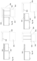
- Fig. 7A-D is a side view of an embodiment of the present invention wherein a delivery vehicle carrying a container is placed in a testing station. Since the delivery vehicle does not have a lifting platform arranged above the container, like the previously described handling vehicles, it is not possible for the delivery vehicle to place the container in the testing station with out help.
- the delivery vehicle with the container on top therefor fits into the testing station.
- the testing station therefor has tracks in the bottom in order to allow the delivery vehicle to manouever itself with the container on top into the testing station.
- the testing station lowers the measuring platform onto the container.
- the measuring platform is lowered using, wire, belts, chains, rope or similar attached to an electric motor.
- the measuring platform fits over the top opening.
- the platform further comprises measuring equipment attached to the underside.
- the measuring equipment is placed so that it fits inside the container when the platform is placed on the container.
- the measuring equipment can be a temperature sensor, a moisture sensor, a gas sensor and/or cameras. Any other kind of measuring equipment that can be mounted onto the measuring platform can be used.
- the data can be sent over to the central computer system. When the data is collected the delivery vehicle with the container on top can be transported to the next destination.
- Fig. 8A-D is a side view of an alternative embodiment of the present invention wherein a container handling vehicle with a cantilever solution places a container in a testing station for measurements.
- the container handling vehicle approaches the testing station carrying a container from the storage system.
- the container handling vehicle places the container on the base of the testing station.
- the container handling vehicle backs away giving the testing station access to the contents of the container via its top opening.
- the testing station lowers a measuring platform onto the container.
- the measuring platform is lowered using, wire, belts, chains, rope or similar attached to an electric motor.
- the measuring platform fits over the top opening.
- the platform further comprises measuring equipment attached to the underside. The measuring equipment are placed so that it fits inside the container when the platform is placed on the container.
- the measuring equipment can be a temperature sensor, a moisture sensor, a gas sensor and/or cameras. Any other kind of measuring equipment that can be mounted onto the measuring platform can be used.
- the collected data can be sent to a central computer system.
- the central computer system can store and analyse the data.
- the data can be stored together with the ID of the container in order to keep track of the condition of the content of the container.
- the central computer system can send instruction to a container handling vehicle to transport the container to a destination dependent on the condition of the items in the container. If the items are in a condition that is acceptable for distribution to customers, the container with the items are transported either to a station where the desired items can be picked for further distribution, or the container with the items can be transported back into the storage system.
- the container can be transported to a destination where the spoiled items can be removed from the container. After the items have been removed the container is either transported back to the storage system or to a port for further distribution to a picking station where items are picked for further distribution to customers.
- Fig. 9A-C is a side view of an alternative embodiment of the present invention wherein a delivery vehicle carrying a container is placed in a testing station. Since the delivery vehicle does not have a lifting platform holding the container it is not possible for the delivery vehicle to place the container in the testing station with out help.
- the delivery vehicle with the container on top therefor fits into the testing station.
- the testing station has tracks in the base of the testing station in order to allow the delivery vehicle to manouever itself with the container on top into the testing station.
- the testing station lowers the measuring platform onto the container.
- the measuring platform is lowered using, wire, belts, chains, rope or similar attached to an electric motor.
- the measuring platform fits over the top opening.
- the platform further comprises measuring equipment attached to the underside.
- the measuring equipment are placed so that it fits inside the container when the platform is placed on the container.
- the measuring equipment can be a temperature sensor, a moisture sensor, a gas sensor and/or cameras. Any other kind of measuring equipment that can be mounted onto the measuring platform can be used.
- the data can be sent over to the central computer system.
- the delivery vehicle with the container on top can be transported to the next destination.
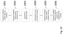
- Fig. 10 is a flowchart describing the steps in the process of the embodiments of the present invention.
- a container handling vehicle or a delivery vehicle transports a container from the storage system.
- the storage system is an automated storage and retrieval system 1 with a framework structure 100, comprising upright members 102, horizontal members 103 and a storage volume comprising storage columns 105 arranged in rows between the upright members 102 and the horizontal members 103.
- storage containers 106 also known as bins, are stacked one on top of one another to form stacks 107.
- the container handling vehicle or the delivery vehicle transports the container to the measuring station. Dependent on the vehicle transporting the container, the container is either placed in the testing station or the delivery vehicle with the container on top is parked in the testing station.
- the testing station lowers the measuring platform, the measuring platform fits over the top of the container.
- the measuring platform has sensors attached to it.
- the sensors can be a temperature sensor, a gas sensor, a moisture detector and/or a camera.
- the data from the sensors are collected and sent to the central computer system.
- the central computer system the collected data is stored together with the ID of the container. Further the data can be analyzed and the result to the analysis is the basis for the conclution of where the container and its content go after the measuring.
- the central computer system sends instructions to the container handling vehicle or the delivery vehicle telling it to transport the container to a predetermined destination.
- the predetermined destination is dependent on the quality of the items in the container.
- the container is either transported to a port and from there it is transported to a picking station where items are collected for further distribution, alternatively the container can be transported back to the storage grid structure. If the items in the container is of a quality that is not good enough for human consumption, it is transported to a destination where the spoiled items are picked from the container and disposed of according to prescribed instructions.
Description
- The present invention relates to an automated storage and retrieval system for storage and retrieval of containers, in particular to a system and a method for performing measurements in a container when placed in a testing station comprising measuring equipment.
-
EP3326452 A1 describes an illuminated cultivation storage system and a method for cultivating crops in an illuminated cultivation storage system. The system comprises a three-dimensional framework structure forming a grid of vertical and horizontal storage tunnels, a plurality of storage containers for holding growing crops. The storage containers being configured to be introduced into the framework structure. The system further has a plurality of lighting device, a transport system, and an illumination controller. Further, the interior of the framework structure exhibits distinguishable climate zones, each climate zone having a set of growth parameters including temperature. The system further comprises a growth monitoring station which includes sensors for determining a current growth status of crops and a growth controller connected to the transport system and being configured to operate the transport system in order to return storage containers to a designated climate zone based on the determined growth status. -
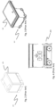
Fig. 1 of the present disclosure discloses a typical prior art automated storage andretrieval system 1 with aframework structure 100 andFig. 2 and 3 discloses two different prior art container handling vehicles 201,301 suitable for operating on such asystem 1. - The
framework structure 100 comprisesupright members 102,horizontal members 103 and a storage volume comprisingstorage columns 105 arranged in rows between theupright members 102 and thehorizontal members 103. In thesestorage columns 105storage containers 106, also known as bins, are stacked one on top of one another to formstacks 107. Themembers - The
framework structure 100 of the automated storage andretrieval system 1 comprises arail system 108 arranged across the top offramework structure 100, on which rail system 108 a plurality of container handling vehicles 201,301 are operated to raisestorage containers 106 from, andlower storage containers 106 into, thestorage columns 105, and also to transport thestorage containers 106 above thestorage columns 105. Therail system 108 comprises a first set ofparallel rails 110 arranged to guide movement of the container handling vehicles 201,301 in a first direction X across the top of theframe structure 100, and a second set ofparallel rails 111 arranged perpendicular to the first set ofrails 110 to guide movement of the container handling vehicles 201,301 in a second direction Y which is perpendicular to the first direction X.Containers 106 stored in thecolumns 105 are accessed by the container handling vehicles through access openings 112 in therail system 108. The container handling vehicles 201,301 can move laterally above thestorage columns 105, i.e. in a plane which is parallel to the horizontal X-Y plane. - The
upright members 102 of theframework structure 100 may be used to guide the storage containers during raising of the containers out from and lowering of the containers into thecolumns 105. Thestacks 107 ofcontainers 106 are typically self-supportive. - Each prior art container handling vehicle 201,301 comprises a vehicle body 201a,301a, and first and second sets of wheels 201b,301b,201c,301c which enable the lateral movement of the container handling vehicles 201,301 in the X direction and in the Y direction, respectively. In
Fig. 2 and 3 two wheels in each set are fully visible. The first set of wheels 201b,301b is arranged to engage with two adjacent rails of thefirst set 110 of rails, and the second set of wheels 201c,301c is arranged to engage with two adjacent rails of thesecond set 111 of rails. At least one of set wheels 201b,301b,201c,301c can be lifted and lowered, so that the first set of wheels 201b,301b and/or the second set of wheels 201c,301c can be engaged with the respective set ofrails - Each prior art container handling vehicle 201,301 also comprises a lifting device (not shown) for vertical transportation of
storage containers 106, e.g. raising astorage container 106 from, and lowering astorage container 106 into, astorage column 105. The lifting device comprises one or more gripping / engaging devices which are adapted to engage astorage container 106, and which gripping / engaging devices can be lowered from the vehicle 201,301 so that the position of the gripping / engaging devices with respect to the vehicle 201,301 can be adjusted in a third direction Z which is orthogonal the first direction X and the second direction Y. Parts of the gripping device of thecontainer handling vehicle 301 is shown in infig. 3 and is indicated with reference number 304. The gripping device of thecontainer handling device 201 is located within the vehicle body 301a inFig. 2 . - Conventionally, and also for the purpose of this application, Z=1 identifies the uppermost layer of storage containers, i.e. the layer immediately below the
rail system 108, Z=2 the second layer below therail system 108, Z=3 the third layer etc. In the exemplary prior art disclosed inFig. 1 , Z=8 identifies the lowermost, bottom layer of storage containers. Similarly, X=1... n and Y=1... n identifies the position of eachstorage column 105 in the horizontal plane. Consequently, as an example, and using the Cartesian coordinate system X, Y, Z indicated inFig. 1 , the storage container identified as 106' inFig. 1 can be said to occupy storage position X=10, Y=2, Z=3. The container handling vehicles 201,301 can be said to travel in layer Z=0, and eachstorage column 105 can be identified by its X and Y coordinates. - The storage volume of the
framework structure 100 has often been referred to as agrid 104, where the possible storage positions within this grid is referred to as a storage cell. Each storage column may be identified by a position in an X- and Y-direction, while each storage cell may be identified by a container number in the X-, Y and Z-direction. - Each prior art container handling vehicle 201,301 comprises a storage compartment or space for receiving and stowing a
storage container 106 when transporting thestorage container 106 across therail system 108. The storage space may comprise a cavity arranged centrally within the vehicle body 201a as shown inFig. 2 and as described in e.g.WO2015/193278A1 . -
Fig. 3 shows an alternative configuration of acontainer handling vehicle 301 with a cantilever construction. Such a vehicle is described in detail in e.g.NO317366 - The central cavity
container handling vehicles 201 shown inFig. 2 may have a footprint that covers an area with dimensions in the X and Y directions which is generally equal to the lateral extent of astorage column 105, e.g. as is described inWO2015/193278A1 . - The term 'lateral' used herein may mean 'horizontal'.
- Alternatively, the central cavity container handling vehicles 101 may have a footprint which is larger than the lateral area defined by a
storage column 105, e.g. as is disclosed inWO2014/090684A1 . - The
rail system 108 typically comprises rails with grooves into which the wheels of the vehicles are inserted. Alternatively, the rails may comprise upwardly protruding elements, where the wheels of the vehicles comprise flanges to prevent derailing. These grooves and upwardly protruding elements are collectively known as tracks. Each rail may comprise one track, or each rail may comprise two parallel tracks. -
WO2018146304 illustrates a typical configuration ofrail system 108 comprising rails and parallel tracks in both X and Y directions. - In the
framework structure 100, a majority of thecolumns 105 arestorage columns 105,i.e. columns 105 wherestorage containers 106 are stored instacks 107. However, somecolumns 105 may have other purposes. Infig. 1 ,columns storage containers 106 so that they can be transported to an access station (not shown) where thestorage containers 106 can be accessed from outside of theframework structure 100 or transferred out of or into theframework structure 100. Within the art, such a location is normally referred to as a 'port' and the column in which the port is located may be referred to as a 'port column' 119,120. The transportation to the access station may be in any direction, that is horizontal, tilted and/or vertical. For example, thestorage containers 106 may be placed in a random ordedicated column 105 within theframework structure 100, then picked up by any container handling vehicle and transported to a port column 119,120 for further transportation to an access station. Note that the term 'tilted' means transportation ofstorage containers 106 having a general transportation orientation somewhere between horizontal and vertical. - In
fig. 1 , thefirst port column 119 may for example be a dedicated drop-off port column where the container handling vehicles 201,301 can drop offstorage containers 106 to be transported to an access or a transfer station, and thesecond port column 120 may be a dedicated pick-up port column where the container handling vehicles 201,301 can pick upstorage containers 106 that have been transported from an access or a transfer station. - The access station may typically be a picking or a stocking station where product items are removed from or positioned into the
storage containers 106. In a picking or a stocking station, thestorage containers 106 are normally not removed from the automated storage andretrieval system 1, but are returned into theframework structure 100 again once accessed. A port can also be used for transferring storage containers to another storage facility (e.g. to another framework structure or to another automated storage and retrieval system), to a transport vehicle (e.g. a train or a lorry), or to a production facility. - A conveyor system comprising conveyors is normally employed to transport the storage containers between the port columns 119,120 and the access station.
- If the port columns 119,120 and the access station are located at different levels, the conveyor system may comprise a lift device with a vertical component for transporting the
storage containers 106 vertically between the port column 119,120 and the access station. - The conveyor system may be arranged to transfer
storage containers 106 between different framework structures, e.g. as is described inWO2014/075937A1 - When a
storage container 106 stored in one of thecolumns 105 disclosed inFig. 1 is to be accessed, one of the container handling vehicles 201,301 is instructed to retrieve thetarget storage container 106 from its position and transport it to the drop-offport column 119. This operation involves moving the container handling vehicle 201,301 to a location above thestorage column 105 in which thetarget storage container 106 is positioned, retrieving thestorage container 106 from thestorage column 105 using the container handling vehicle's 201,301 lifting device (not shown), and transporting thestorage container 106 to the drop-offport column 119. If thetarget storage container 106 is located deep within astack 107, i.e. with one or a plurality ofother storage containers 106 positioned above thetarget storage container 106, the operation also involves temporarily moving the above-positioned storage containers prior to lifting thetarget storage container 106 from thestorage column 105. This step, which is sometimes referred to as "digging" within the art, may be performed with the same container handling vehicle that is subsequently used for transporting the target storage container to the drop-offport column 119, or with one or a plurality of other cooperating container handling vehicles. Alternatively, or in addition, the automated storage andretrieval system 1 may have container handling vehicles specifically dedicated to the task of temporarily removing storage containers from astorage column 105. Once thetarget storage container 106 has been removed from thestorage column 105, the temporarily removed storage containers can be repositioned into theoriginal storage column 105. However, the removed storage containers may alternatively be relocated to other storage columns. - When a
storage container 106 is to be stored in one of thecolumns 105, one of the container handling vehicles 201,301 is instructed to pick up thestorage container 106 from the pick-upport column 120 and transport it to a location above thestorage column 105 where it is to be stored. After any storage containers positioned at or above the target position within thestorage column stack 107 have been removed, the container handling vehicle 201,301 positions thestorage container 106 at the desired position. The removed storage containers may then be lowered back into thestorage column 105, or relocated to other storage columns. - For monitoring and controlling the automated storage and
retrieval system 1, e.g. monitoring and controlling the location ofrespective storage containers 106 within theframework structure 100, the content of eachstorage container 106; and the movement of the container handling vehicles 201,301 so that a desiredstorage container 106 can be delivered to the desired location at the desired time without the container handling vehicles 201,301 colliding with each other, the automated storage andretrieval system 1 comprises a control system 500 which typically is computerized and which typically comprises a database for keeping track of thestorage containers 106. -
Figure 4 describes a delivery vehicle. The delivery vehicles comprise a base with the same setup of wheels as on the container handling vehicles. The wheel base unit features a wheel arrangement having a first set of wheels for movement in a first direction upon a rail grid (i.e. any of the top rail grid and the transfer rail grid) and a second set of wheels for movement in a second direction perpendicular to the first direction. Each set of wheels comprises two pairs of wheels arranged on opposite sides of the wheel base unit. To change the direction in which the wheel base unit may travel upon the rail grid, one of the sets of wheels is connected to a wheel displacement assembly. The wheel displacement assembly is able to lift and lower the connected set of wheels relative to the other set of wheels such that only the set of wheels travelling in a desired direction is in contact with the rail grid. The wheel displacement assembly is driven by an electric motor. Further, two electric motors, powered by a rechargeable battery, are connected to the set of wheels to move the wheel base unit in the desired direction. The horizontal periphery of the wheel base unit is dimensioned to fit within the horizontal area defined by a grid cell of the rail grid such that two-wheel base units may pass each other on any adjacent grid cells of the rail grid. In other words, the wheel base unit may have a footprint, i.e. an extent in the X and Y directions, which is generally equal to the horizontal area of a grid cell, i.e. the extent of a grid cell in the X and Y directions, e.g. as is described inWO2015/193278A1 . - A problem with the prior art solutions is that if there are perishable items in the storage there is a need for measuring the freshness of the products and the conditions the items are stored in. There is however a problem with getting accurate readings of the items without having to turn to costly solutions that require expensive equipment or extensive rebuilds. It is therefore an object of the present invention to solve the problems mentioned above.
- The present invention is set forth and characterized in the
independent claims 1 and 11, respectively a system and a method, while the dependent claims describe other characteristics of the invention. - In one aspect, the invention is related to a system for performing measurements in storage containers for storing items, the storage containers are stored in an automated storage system comprising a framework structure forming a three-dimensional storage grid structure for storing the storage containers, where the grid structure forms vertical storage columns each having a horizontal area defined by the size of an access opening of the vertical storage columns and where a rail system is arranged on the framework structure defining the circumference of each access opening on top of each storage column, the rail system providing available routes for container handling vehicles handling and transferring the storage containers to and from the storage columns, and wherein said system is wherein the system further comprises a testing station, accessible to a container handling vehicle via the rail system, with measuring equipment for measuring atmospheric conditions and for performing measurements in said storage container and where the testing station is configured to communicate measurement data to a computer system
- Further the testing station may comprise an upper part to which the measuring platform is attached, a lower part for receiving the container and a part connecting the upper and the lower part. Also the testing station may have a space for accommodating a container between the upper and the lower part, and the testing station may be adapted to raise and lower the measuring platform.
- The testing station may be adapted to accommodate a container handling vehicle with a container on top.
- the measuring platform may be raised and lowered by a rope, band or wire controlled by an electric motor, or the measuring platform may be raised and lowered by a robotic arm, and the measuring platform comprises temperature measurement equipment, moisture detectors, gas detectors and cameras.
- In a second aspect the invention is directed to a method according to claim 11 of performing measurements in a container for storing in an automated storage system comprising a three-dimensional grid (4) of an underlying storage system (1), at least one container handling vehicle for transporting containers, ports for picking items for further distribution, a central computer system for controlling the operation of the storage system, and wherein said method comprises the steps of:
placing a container in a testing station by means of a container handling vehicle, lowering a measuring platform attached to the testing station onto the container, performing measurements, transmitting the measurements to the central computer system, performing an analysis based upon the measurements, transmitting instructions based on the analysis to a container handling vehicle, raising the measuring platform, transporting the container to another destination by means of a container handling vehicle. Performing measurements of temperature, moisture and gas level in the container and by using cameras for visual inspection of the items. - Following drawings are appended to facilitate the understanding of the invention. The drawings show embodiments of the invention, which will now be described by way of example only, where:
-
Fig. 1 is a perspective view of a framework structure of a prior art automated storage and retrieval system. -
Fig. 2 is a perspective view of a prior art container handling vehicle having a centrally arranged cavity for carrying storage containers therein. -
Fig. 3 is a perspective view of a prior art container handling vehicle having a cantilever for carrying storage containers underneath. -
Fig. 4 is a side view of a delivery vehicle. -
Fig. 5A-D is a side view of an embodiment of the present invention wherein a container handling vehicle with a central cavity places a container in a testing station for measurements. -
Fig. 6A-D is a side view of an embodiment of the present invention wherein a container handling vehicle with a cantilever solution places a container in a testing station for measurements. -
Fig. 7A-C is a side view of an embodiment of the present invention wherein a delivery vehicle carrying a container is placed in a testing station. -
Fig. 8A-D is a side view of an alternative embodiment of the present invention wherein a container handling vehicle with a cantilever solution places a container in a testing station for measurements. -
Fig. 9A-C is a side view of an alternative embodiment of the present invention wherein a delivery vehicle carrying a container is placed in a testing station. -
Fig. 10 is a flowchart describing the steps in the process of the embodiments of the present invention. - In the following, embodiments of the invention will be discussed in more detail with reference to the appended drawings. It should be understood, however, that the drawings are not intended to limit the invention to the subject-matter depicted in the drawings.
- The
framework structure 100 of the automated storage andretrieval system 1 is constructed in accordance with the priorart framework structure 100 described above in connection withFigs. 1-3 , i.e. a number ofupright members 102 and a number ofhorizontal members 103, which are supported by theupright members 102, and further that theframework structure 100 comprises a first,upper rail system 108 in the X direction and Y direction. - The
framework structure 100 further comprises storage compartments in the form ofstorage columns 105 provided between themembers storage containers 106 are stackable instacks 107 within thestorage columns 105. - The
framework structure 100 can be of any size. In particular it is understood that the framework structure can be considerably wider and/or longer and/or deeper than disclosed inFig. 1 . For example, theframework structure 100 may have a horizontal extent of more than 700x700 columns and a storage depth of more than twelve containers. - Embodiments of the automated storage and retrieval system according to the invention will now be discussed in more detail with reference to
Figs. 5A-D ,6A-D ,7A-C ,8A-D ,9A-C and10 . - In a preferred embodiment of the present invention the testing station is comprised of a top portion. This top portion houses the measuring platform. The measuring platform comprises at least one sensor. The at least one sensor is used to measure a at least one atmospheric condition in a storage container. One such atmospheric condition might be the temperature in the container, further the sensor can be used to detect the presence of gasses that is released during rotting of food. One such gas can be methane. Other gasses that are released during decay of food is carbon dioxide and hydrogen sulphide. In the case of carbon dioxide and hydrogen sulphide they are heavier than air and will therefore collect at the bottom of the container. The sensors for sensing carbon dioxide and hydrogen sulphide can therefore be attached to a probe that is lowered into the container. Alternatively there can be holes in the sides or in the bottom of the containers into which it is possible to insert sensors. In yet another solution there can be a slit or a tunnel e.g. along the inside edges of the container wherein the probe can be lowered into the bottom of the container without the content of the container hindering the probe. Further there can be detectors to detect moisture. The presense of moisture is due to the fact that during rotting of food the cells of the food is broken down and the liquid in the cells leaks out. A further type of measuring equipment can be a camera. The camera can take pictures into the container, i.e., of the contents, in order to detect if there is any sign of rotting food. The camera can be an ordinary camera that takes colour images in order to detect if there is marks on the food, like e.g., brown spots on bananas, or discoloration on the surface due to milldue. Alternatively or in addition, there can be used a camera that has ultraviolet light in order to detect mold.
- There is also the possibility to use UV light in order to kill bacteria on the food. There is further a possibility to use UV light to kill mold. Therefor the measuring platform can have a UV light source that can be used to both detect rotting food and to kill bacteria and mold on the food and in the container. The difference between using the UV light source to detect decay and to kill bacteria and mold is the wavelength of the light and the power of the light souce.
-
Fig. 5A-D is a side view of an embodiment of the present invention wherein a container handling vehicle with a central cavity places a container in a testing station for measurements. The container handling vehicle with a container in its central cavity moves into the testing station. The container is lowered down into a cavity underneath the container handling vehicle. After the container handling vehicle has placed the container in the testing station, the container handling vehicle moves away. After it has moved away, the measuring equipment is lowered down on a measuring platform. The testing station lowers a measuring platform onto the container. The measuring platform is lowered using lines attached to an electric motor. These lines can be wire, belts, chains, rope or similar. The measuring platform fits over the top opening. The platform further comprises measuring equipment attached to the underside. The measuring equipment is placed so that it fits inside the container when the platform is placed on the container. The measuring equipment can be a temperature sensor, a moisture sensor, a gas sensor and/or cameras. Any other kind of measuring equipment that can be mounted onto the measuring platform can be used. After the measuring equipment has collected the data, it can be sent to a central computer system. The central computer system can store the data together with the ID of the container in order to keep track of the condition of the content of the container. Based on the conditions of the content of the container, the central computer system can send instruction to a container handling vehicle to transport the container to a destination dependent on the condition of the items in the container. If the items are in a contidition that is acceptable for distribution to customers, the container with the items are transported either to a station where the desired items can be picked for further distribution, or the container with the items can be transported back into the storage system. If one or more of the items in the container is of poor quality the container can be transported to a destination where the spoiled items can be removed from the container. After the items have been removed the container is either transported back to the storage system or to a port for further distribution to a picking station where items are picked for further distribution to customers. -
Fig. 6A-D is a side view of an embodiment of the present invention wherein a container handling vehicle with a cantilever solution places a container in a testing station for measurements. The container handling vehicle approaches the testing station carrying a container from the storage system. The container handling vehicle places the container in the testing station. The container handling vehicle backs away giving the testing station access to the contents of the container via its top opening. The testing station lowers a measuring platform onto the container. The measuring platform is lowered using lines attached to an electric motor. These lines can be wire, belts, chains, rope or similar. The measuring platform fits over the top opening. The platform comprises measuring equipment attached to the underside. The measuring equipment is placed, for example, on the underside, so that it fits inside the container when the platform is placed on the container. The measuring equipment can be a temperature sensor, a moisture sensor, a gas sensor and/or cameras. Any other kind of measuring equipment that can be mounted onto the measuring platform can be used. The collected data can be sent to a central computer system. The central computer system can store and analyse the data. The data can be stored together with the ID of the container in order to keep track of the condition of the content of the container. Based on the conditions of the content of the container, the central computer system can send instruction to a container handling vehicle to transport the container to a destination dependent on the condition of the items in the container. If the items are in a contidition that is acceptable for distribution to customers, the container with the items are transported either to a station where the desired items can be picked for further distribution, or the container with the items can be transported back into the storage system. If one or more of the items in the container is of poor quality the container can be transported to a destination where the spoiled items can be removed from the container. After the items have been removed the container is either transported back to the storage system or to a port for further distribution to a picking station where items are picked for further distribution to customers. -
Fig. 7A-D is a side view of an embodiment of the present invention wherein a delivery vehicle carrying a container is placed in a testing station. Since the delivery vehicle does not have a lifting platform arranged above the container, like the previously described handling vehicles, it is not possible for the delivery vehicle to place the container in the testing station with out help. In an embodiment of the present invention the delivery vehicle with the container on top therefor fits into the testing station. In this embodiment the testing station therefor has tracks in the bottom in order to allow the delivery vehicle to manouever itself with the container on top into the testing station. The testing station lowers the measuring platform onto the container. The measuring platform is lowered using, wire, belts, chains, rope or similar attached to an electric motor. The measuring platform fits over the top opening. The platform further comprises measuring equipment attached to the underside. The measuring equipment is placed so that it fits inside the container when the platform is placed on the container. The measuring equipment can be a temperature sensor, a moisture sensor, a gas sensor and/or cameras. Any other kind of measuring equipment that can be mounted onto the measuring platform can be used. After the data from the measuring equipment has been collected the data can be sent over to the central computer system. When the data is collected the delivery vehicle with the container on top can be transported to the next destination. -
Fig. 8A-D is a side view of an alternative embodiment of the present invention wherein a container handling vehicle with a cantilever solution places a container in a testing station for measurements. The container handling vehicle approaches the testing station carrying a container from the storage system. The container handling vehicle places the container on the base of the testing station. The container handling vehicle backs away giving the testing station access to the contents of the container via its top opening. The testing station lowers a measuring platform onto the container. The measuring platform is lowered using, wire, belts, chains, rope or similar attached to an electric motor. The measuring platform fits over the top opening. The platform further comprises measuring equipment attached to the underside. The measuring equipment are placed so that it fits inside the container when the platform is placed on the container. The measuring equipment can be a temperature sensor, a moisture sensor, a gas sensor and/or cameras. Any other kind of measuring equipment that can be mounted onto the measuring platform can be used. The collected data can be sent to a central computer system. The central computer system can store and analyse the data. The data can be stored together with the ID of the container in order to keep track of the condition of the content of the container. Based on the conditions of the content of the container, the central computer system can send instruction to a container handling vehicle to transport the container to a destination dependent on the condition of the items in the container. If the items are in a condition that is acceptable for distribution to customers, the container with the items are transported either to a station where the desired items can be picked for further distribution, or the container with the items can be transported back into the storage system. If one or more of the items in the container is of poor quality the container can be transported to a destination where the spoiled items can be removed from the container. After the items have been removed the container is either transported back to the storage system or to a port for further distribution to a picking station where items are picked for further distribution to customers. -
Fig. 9A-C is a side view of an alternative embodiment of the present invention wherein a delivery vehicle carrying a container is placed in a testing station. Since the delivery vehicle does not have a lifting platform holding the container it is not possible for the delivery vehicle to place the container in the testing station with out help. In an embodiment of the present invention the delivery vehicle with the container on top therefor fits into the testing station. In this embodiment the testing station has tracks in the base of the testing station in order to allow the delivery vehicle to manouever itself with the container on top into the testing station. The testing station lowers the measuring platform onto the container. The measuring platform is lowered using, wire, belts, chains, rope or similar attached to an electric motor. The measuring platform fits over the top opening. The platform further comprises measuring equipment attached to the underside. The measuring equipment are placed so that it fits inside the container when the platform is placed on the container. The measuring equipment can be a temperature sensor, a moisture sensor, a gas sensor and/or cameras. Any other kind of measuring equipment that can be mounted onto the measuring platform can be used. After the data from the measuring equipment has been collected the data can be sent over to the central computer system. When the data is collected the delivery vehicle with the container on top can be transported to the next destination. -
Fig. 10 is a flowchart describing the steps in the process of the embodiments of the present invention. a container handling vehicle or a delivery vehicle transports a container from the storage system. The storage system is an automated storage andretrieval system 1 with aframework structure 100, comprisingupright members 102,horizontal members 103 and a storage volume comprisingstorage columns 105 arranged in rows between theupright members 102 and thehorizontal members 103. In thesestorage columns 105storage containers 106, also known as bins, are stacked one on top of one another to form stacks 107. The container handling vehicle or the delivery vehicle transports the container to the measuring station. Dependent on the vehicle transporting the container, the container is either placed in the testing station or the delivery vehicle with the container on top is parked in the testing station. The testing station lowers the measuring platform, the measuring platform fits over the top of the container. The measuring platform has sensors attached to it. The sensors can be a temperature sensor, a gas sensor, a moisture detector and/or a camera. The data from the sensors are collected and sent to the central computer system. In the central computer system the collected data is stored together with the ID of the container. Further the data can be analyzed and the result to the analysis is the basis for the conclution of where the container and its content go after the measuring. After the measuring is performed, the central computer system sends instructions to the container handling vehicle or the delivery vehicle telling it to transport the container to a predetermined destination. The predetermined destination is dependent on the quality of the items in the container. If the items are of a quality that is good enough to be distributed to consumers, the container is either transported to a port and from there it is transported to a picking station where items are collected for further distribution, alternatively the container can be transported back to the storage grid structure. If the items in the container is of a quality that is not good enough for human consumption, it is transported to a destination where the spoiled items are picked from the container and disposed of according to prescribed instructions. - In the preceding description, various aspects of the delivery vehicle and the automated storage and retrieval system according to the invention have been described with reference to the illustrative embodiment. For purposes of explanation, specific numbers, systems and configurations were set forth in order to provide a thorough understanding of the system and its workings. However, this description is not intended to be construed in a limiting sense. Various modifications and variations of the illustrative embodiment, as well as other embodiments of the system, which are apparent to persons skilled in the art to which the disclosed subject matter pertains, are deemed to lie within the scope of the present invention as defined in the appended claims.
-
- 100
- Framework structure
- 102
- Upright members of framework structure
- 103
- Horizontal members of framework structure
- 104
- Storage grid
- 105
- Storage column
- 106
- Storage container
- 106'
- Particular position of storage container
- 107
- Stack
- 108
- Rail system
- 110
- Parallel rails in first direction (X)
- 110a
- First rail in first direction (X)
- 110b
- Second rail in first direction (X)
- 111
- Parallel rail in second direction (Y)
- 111a
- First rail of second direction (Y)
- 111b
- Second rail of second direction (Y)
- 112
- Access opening
- 119
- First port column
- 120
- Second port column
- 201
- Prior art storage container vehicle
- 201a
- Vehicle body of the storage container vehicle 101
- 201b
- Drive means / wheel arrangement, first direction (X)
- 201c
- Drive means / wheel arrangement, second direction (Y)
- 301
- Prior art cantilever storage container vehicle
- 301a
- Vehicle body of the storage container vehicle 101
- 301b
- Drive means in first direction (X)
- 301c
- Drive means in second direction (Y)
- X
- First direction
- Y
- Second direction
- Z
- Third direction
- 401
- Delivery vehicle
- 501
- Container lifting platform
- 502
- Container
- 503
- Measuring platform
- 504
- Testing station
- 601
- Container placement area.
- 801
- Plate
Claims (13)
- A system for performing measurements in storage containers (502) for storing items, the storage containers (502) are stored in an automated storage system comprising a framework structure (100) forming a three-dimensional storage grid structure (104) for storing the storage containers (502), where the grid structure (104) forms vertical storage columns (105) each having a horizontal area defined by the size of an access opening (112) of the vertical storage columns (105) and where a rail system (108) is arranged on the framework structure (100) defining the circumference of each access opening (112) on top of each storage column (105), the rail system (108) providing available routes for container handling vehicles (201) handling and transferring the storage containers (502) to and from the storage columns (105), and wherein said system is characterized in that the system further comprises a testing station (504), accessible to a container handling vehicle via the rail system (108), with measuring equipment for measuring atmospheric conditions and for performing measurements in said storage container (502) and where the testing station (504) is configured to communicate measurement data to a computer system, the testing station comprises an upper part (505) to which a measuring platform (503) with measuring equipment is attached, a lower part (601) for holding a container (502), and connection means for connecting the upper part (505) and the lower part (601) and the testing station comprises a lifting device adapted to raise and lower the measuring platform (503).
- The system according to claim 1 wherein the lower part (601) comprises a cavity underneath a set of rails and into which cavity a storage container (502) can be lowered.
- The system according to claim 1 wherein the lower part (601) comprises a plate (801) with a set of tracks on them.
- The system according to any of claims 1 to 3 wherein the testing station comprises a space between the upper part (505) and the lower part (601) adapted for accommodating a storage container (502).
- The system according to any preceding claim wherein the testing station is adapted to accommodate a container handling vehicle with a storage container (502) on top.
- The system according to claim 1-5 wherein the measuring equipment (503) is raised and lowered by a rope, band or wire controlled by an electric motor.
- The system according to claim 1-6 wherein the measuring equipment is raised and lowered by a robotic arm.
- The system according to any of the claims 1-5 wherein the measuring equipment comprises temperature measurement equipment, moisture detectors, gas detectors and/or cameras.
- The system according to any of the previous claims, further comprising an UV light source for detecting mold on the items stored in the storage container (502).
- The system according to any of the previous claims, further comprising UV-C light source for killing mold, virus and bacteria on the items stored in the storage container (502).
- A method for performing measurements in storage containers (502) for storing items using a testing station (504), wherein the storage containers (502) are stored in an automated storage system comprising a framework structure (100) forming a three-dimensional storage grid structure (104) for storing the storage containers (502), where the grid structure (104) forms vertical storage columns (105) each having a horizontal area defined by the size of an access opening (112) of the vertical storage columns (105) and where a rail system (108) is arranged on the framework structure (100) defining the circumference of each access opening (112) on top of each storage column (105), the rail system (108) providing available routes for container handling vehicles (201) handling and transferring the storage containers (502) to and from the storage columns (105), each vehicle (201, 301, 401) comprising a vehicle controller (230) communicating with a central computer system controlling the operation of the storage system, and wherein said method comprises the steps of:- placing a storage container (502) in the testing station (504) by means of a container handling vehicle (201, 301, 401),- offering up a measuring equipment (503) attached to the testing station (504) onto the storage container (502),- performing measurements to collect measurement data,- transmitting the measurement data to a computer system,- storing the transmitted measurement data and performing an analysis of the measurement data,- transmitting instructions, regarding where to transport the container, from the central computer system to a container handling vehicle based on the result of the analysis,- raising the measuring equipment,- transporting the storage container (502) to a next destination by means of a container handling vehicle.
- The method according to claim 11, by performing measurements of temperature, moisture and/or gas level in the storage container (502) and/or by using cameras for visual inspection of the items.
- The method according to claim 12 wherein the gas detectors are lowered into the storage container (502).
Applications Claiming Priority (2)
| Application Number | Priority Date | Filing Date | Title |
|---|---|---|---|
| NO20200120A NO345921B1 (en) | 2020-01-31 | 2020-01-31 | System and method for performing measurements in storage containers |
| PCT/EP2021/051779 WO2021151906A1 (en) | 2020-01-31 | 2021-01-26 | Sensor testing station |
Related Child Applications (1)
| Application Number | Title | Priority Date | Filing Date |
|---|---|---|---|
| EP24160715.9 Division-Into | 2024-02-29 |
Publications (2)
| Publication Number | Publication Date |
|---|---|
| EP4097029A1 EP4097029A1 (en) | 2022-12-07 |
| EP4097029B1 true EP4097029B1 (en) | 2024-04-24 |
Family
ID=74347085
Family Applications (1)
| Application Number | Title | Priority Date | Filing Date |
|---|---|---|---|
| EP21702233.4A Active EP4097029B1 (en) | 2020-01-31 | 2021-01-26 | Sensor testing station |
Country Status (8)
| Country | Link |
|---|---|
| US (1) | US20230056161A1 (en) |
| EP (1) | EP4097029B1 (en) |
| JP (1) | JP2023512240A (en) |
| KR (1) | KR20220132616A (en) |
| CN (1) | CN115038655A (en) |
| CA (1) | CA3164334A1 (en) |
| NO (1) | NO345921B1 (en) |
| WO (1) | WO2021151906A1 (en) |
Family Cites Families (13)
| Publication number | Priority date | Publication date | Assignee | Title |
|---|---|---|---|---|
| WO2014066844A2 (en) * | 2012-10-26 | 2014-05-01 | GreenTech Agro LLC | Self-sustaining artificially controllable environment within a storage container or other enclosed space |
| NO334806B1 (en) | 2012-11-13 | 2014-06-02 | Jakob Hatteland Logistics As | storage System |
| NO335839B1 (en) | 2012-12-10 | 2015-03-02 | Jakob Hatteland Logistics As | Robot for transporting storage containers |
| NO337544B1 (en) | 2014-06-19 | 2016-05-02 | Jakob Hatteland Logistics As | Remote controlled vehicle assembly to pick up storage containers from a storage system |
| CN107429512B (en) * | 2015-04-15 | 2021-07-09 | 奥卡多创新有限公司 | Storage system and method |
| DK3326452T3 (en) * | 2016-11-24 | 2020-09-07 | Heliospectra Ab | CULTIVATION STORAGE SYSTEM |
| NO20170216A1 (en) | 2017-02-13 | 2018-08-14 | Autostore Tech As | Rail arrangement for wheeled vehicles in a storage system |
| CN109720830B (en) * | 2017-10-30 | 2024-02-20 | 杭州海康机器人股份有限公司 | Loading device of automatic guiding carrier, control method of loading device and loading control system |
| GB201720633D0 (en) * | 2017-12-11 | 2018-01-24 | Ocado Innovation Ltd | Robotic parking device and handling method |
| CN207844078U (en) * | 2018-02-08 | 2018-09-11 | 深圳捷佳德现金自动化处理设备有限公司 | A kind of high density intelligent warehousing system using robot |
| NO344302B1 (en) * | 2018-04-25 | 2019-10-28 | Autostore Tech As | Automated storage and retrieval system comprising a relay module and a method of operating such a system |
| GB201809020D0 (en) * | 2018-06-01 | 2018-07-18 | Ocado Innovation Ltd | Control device and method for item verification |
| CN110304388B (en) * | 2019-07-10 | 2021-03-02 | 四川易景智能终端有限公司 | Intelligent scheduling system for unmanned warehouse |
-
2020
- 2020-01-31 NO NO20200120A patent/NO345921B1/en unknown
-
2021
- 2021-01-26 US US17/796,020 patent/US20230056161A1/en active Pending
- 2021-01-26 EP EP21702233.4A patent/EP4097029B1/en active Active
- 2021-01-26 JP JP2022546003A patent/JP2023512240A/en active Pending
- 2021-01-26 WO PCT/EP2021/051779 patent/WO2021151906A1/en active Search and Examination
- 2021-01-26 KR KR1020227029576A patent/KR20220132616A/en unknown
- 2021-01-26 CA CA3164334A patent/CA3164334A1/en active Pending
- 2021-01-26 CN CN202180012189.4A patent/CN115038655A/en active Pending
Also Published As
| Publication number | Publication date |
|---|---|
| JP2023512240A (en) | 2023-03-24 |
| CA3164334A1 (en) | 2021-08-05 |
| NO345921B1 (en) | 2021-10-25 |
| CN115038655A (en) | 2022-09-09 |
| NO20200120A1 (en) | 2021-08-02 |
| KR20220132616A (en) | 2022-09-30 |
| WO2021151906A1 (en) | 2021-08-05 |
| US20230056161A1 (en) | 2023-02-23 |
| EP4097029A1 (en) | 2022-12-07 |
Similar Documents
| Publication | Publication Date | Title |
|---|---|---|
| US20230053090A1 (en) | System and method for performing measurements in storage containers | |
| US20230065714A1 (en) | Conveyor system | |
| EP4097029B1 (en) | Sensor testing station | |
| US20230040663A1 (en) | A system and method for monitoring atmospheric conditions in an automated storage and retrieval system | |
| US20230211953A1 (en) | Automated storage and retrieval system for storing fresh food and produce | |
| US20230286758A1 (en) | System and method for detection of anomalies in the tracks on a three-dimensional storage system | |
| US20220241627A1 (en) | An automated storage and retrieval system with fire detection device and methods of locating and/or verifying fire or smoke in an automated storage and retrieval system | |
| NO20211029A1 (en) | ||
| WO2022228894A1 (en) | Container handler and method for handling a storage container | |
| WO2023083658A1 (en) | A vehicle-portable grid assessment device | |
| NO20220501A1 (en) | Positioning tool | |
| NO20210679A1 (en) | An automated storage and retrieval system with a dynamic storage section and a method of using same |
Legal Events
| Date | Code | Title | Description |
|---|---|---|---|
| STAA | Information on the status of an ep patent application or granted ep patent |
Free format text: STATUS: UNKNOWN |
|
| STAA | Information on the status of an ep patent application or granted ep patent |
Free format text: STATUS: THE INTERNATIONAL PUBLICATION HAS BEEN MADE |
|
| PUAI | Public reference made under article 153(3) epc to a published international application that has entered the european phase |
Free format text: ORIGINAL CODE: 0009012 |
|
| STAA | Information on the status of an ep patent application or granted ep patent |
Free format text: STATUS: REQUEST FOR EXAMINATION WAS MADE |
|
| 17P | Request for examination filed |
Effective date: 20220823 |
|
| AK | Designated contracting states |
Kind code of ref document: A1 Designated state(s): AL AT BE BG CH CY CZ DE DK EE ES FI FR GB GR HR HU IE IS IT LI LT LU LV MC MK MT NL NO PL PT RO RS SE SI SK SM TR |
|
| DAV | Request for validation of the european patent (deleted) | ||
| DAX | Request for extension of the european patent (deleted) | ||
| GRAP | Despatch of communication of intention to grant a patent |
Free format text: ORIGINAL CODE: EPIDOSNIGR1 |
|
| STAA | Information on the status of an ep patent application or granted ep patent |
Free format text: STATUS: GRANT OF PATENT IS INTENDED |
|
| INTG | Intention to grant announced |
Effective date: 20231010 |
|
| GRAJ | Information related to disapproval of communication of intention to grant by the applicant or resumption of examination proceedings by the epo deleted |
Free format text: ORIGINAL CODE: EPIDOSDIGR1 |
|
| STAA | Information on the status of an ep patent application or granted ep patent |
Free format text: STATUS: REQUEST FOR EXAMINATION WAS MADE |
|
| GRAP | Despatch of communication of intention to grant a patent |
Free format text: ORIGINAL CODE: EPIDOSNIGR1 |
|
| STAA | Information on the status of an ep patent application or granted ep patent |
Free format text: STATUS: GRANT OF PATENT IS INTENDED |
|
| INTC | Intention to grant announced (deleted) | ||
| INTG | Intention to grant announced |
Effective date: 20240201 |
|
| GRAS | Grant fee paid |
Free format text: ORIGINAL CODE: EPIDOSNIGR3 |
|
| GRAA | (expected) grant |
Free format text: ORIGINAL CODE: 0009210 |
|
| STAA | Information on the status of an ep patent application or granted ep patent |
Free format text: STATUS: THE PATENT HAS BEEN GRANTED |
|
| AK | Designated contracting states |
Kind code of ref document: B1 Designated state(s): AL AT BE BG CH CY CZ DE DK EE ES FI FR GB GR HR HU IE IS IT LI LT LU LV MC MK MT NL NO PL PT RO RS SE SI SK SM TR |
|
| REG | Reference to a national code |
Ref country code: GB Ref legal event code: FG4D |