KR20220128421A - Gas sensing device including a housing having a connection passage formed therein - Google Patents
Gas sensing device including a housing having a connection passage formed therein Download PDFInfo
- Publication number
- KR20220128421A KR20220128421A KR1020227028286A KR20227028286A KR20220128421A KR 20220128421 A KR20220128421 A KR 20220128421A KR 1020227028286 A KR1020227028286 A KR 1020227028286A KR 20227028286 A KR20227028286 A KR 20227028286A KR 20220128421 A KR20220128421 A KR 20220128421A
- Authority
- KR
- South Korea
- Prior art keywords
- housing
- opening
- inner space
- sensor unit
- gas
- Prior art date
Links
- 239000007789 gas Substances 0.000 claims description 155
- 229910052739 hydrogen Inorganic materials 0.000 claims description 27
- 239000001257 hydrogen Substances 0.000 claims description 27
- 230000008878 coupling Effects 0.000 claims description 23
- 238000010168 coupling process Methods 0.000 claims description 23
- 238000005859 coupling reaction Methods 0.000 claims description 23
- 238000010438 heat treatment Methods 0.000 claims description 21
- 238000000034 method Methods 0.000 claims description 15
- 239000007784 solid electrolyte Substances 0.000 claims description 10
- 125000004435 hydrogen atom Chemical class [H]* 0.000 claims 2
- 230000036632 reaction speed Effects 0.000 abstract description 2
- 239000007788 liquid Substances 0.000 description 61
- QVGXLLKOCUKJST-UHFFFAOYSA-N atomic oxygen Chemical compound [O] QVGXLLKOCUKJST-UHFFFAOYSA-N 0.000 description 23
- 239000001301 oxygen Substances 0.000 description 23
- 229910052760 oxygen Inorganic materials 0.000 description 23
- UFHFLCQGNIYNRP-UHFFFAOYSA-N Hydrogen Chemical compound [H][H] UFHFLCQGNIYNRP-UHFFFAOYSA-N 0.000 description 15
- 239000010416 ion conductor Substances 0.000 description 15
- 150000002431 hydrogen Chemical class 0.000 description 13
- 239000012925 reference material Substances 0.000 description 12
- 238000001514 detection method Methods 0.000 description 11
- 239000000463 material Substances 0.000 description 9
- 238000005259 measurement Methods 0.000 description 9
- GPRLSGONYQIRFK-UHFFFAOYSA-N hydron Chemical compound [H+] GPRLSGONYQIRFK-UHFFFAOYSA-N 0.000 description 8
- 229910052751 metal Inorganic materials 0.000 description 8
- 239000002184 metal Substances 0.000 description 8
- 239000003921 oil Substances 0.000 description 6
- BASFCYQUMIYNBI-UHFFFAOYSA-N platinum Chemical compound [Pt] BASFCYQUMIYNBI-UHFFFAOYSA-N 0.000 description 6
- 238000007789 sealing Methods 0.000 description 5
- 230000008901 benefit Effects 0.000 description 4
- 239000012528 membrane Substances 0.000 description 4
- 239000003566 sealing material Substances 0.000 description 4
- 229910001233 yttria-stabilized zirconia Inorganic materials 0.000 description 4
- 239000000853 adhesive Substances 0.000 description 3
- 230000001070 adhesive effect Effects 0.000 description 3
- 238000001704 evaporation Methods 0.000 description 3
- 229910002076 stabilized zirconia Inorganic materials 0.000 description 3
- UGFAIRIUMAVXCW-UHFFFAOYSA-N Carbon monoxide Chemical compound [O+]#[C-] UGFAIRIUMAVXCW-UHFFFAOYSA-N 0.000 description 2
- MCMNRKCIXSYSNV-UHFFFAOYSA-N Zirconium dioxide Chemical compound O=[Zr]=O MCMNRKCIXSYSNV-UHFFFAOYSA-N 0.000 description 2
- 230000000903 blocking effect Effects 0.000 description 2
- 239000011575 calcium Substances 0.000 description 2
- 229910002091 carbon monoxide Inorganic materials 0.000 description 2
- 150000001875 compounds Chemical class 0.000 description 2
- 230000006866 deterioration Effects 0.000 description 2
- 238000010586 diagram Methods 0.000 description 2
- 230000000694 effects Effects 0.000 description 2
- 238000005516 engineering process Methods 0.000 description 2
- 229910044991 metal oxide Inorganic materials 0.000 description 2
- 150000004706 metal oxides Chemical class 0.000 description 2
- 239000000203 mixture Substances 0.000 description 2
- 229910052697 platinum Inorganic materials 0.000 description 2
- 238000010248 power generation Methods 0.000 description 2
- 239000004065 semiconductor Substances 0.000 description 2
- 238000000926 separation method Methods 0.000 description 2
- 239000000758 substrate Substances 0.000 description 2
- 101150058765 BACE1 gene Proteins 0.000 description 1
- OYPRJOBELJOOCE-UHFFFAOYSA-N Calcium Chemical compound [Ca] OYPRJOBELJOOCE-UHFFFAOYSA-N 0.000 description 1
- OKTJSMMVPCPJKN-UHFFFAOYSA-N Carbon Chemical compound [C] OKTJSMMVPCPJKN-UHFFFAOYSA-N 0.000 description 1
- 239000004215 Carbon black (E152) Substances 0.000 description 1
- -1 Cu/CuO Chemical class 0.000 description 1
- YZCKVEUIGOORGS-OUBTZVSYSA-N Deuterium Chemical compound [2H] YZCKVEUIGOORGS-OUBTZVSYSA-N 0.000 description 1
- FYYHWMGAXLPEAU-UHFFFAOYSA-N Magnesium Chemical compound [Mg] FYYHWMGAXLPEAU-UHFFFAOYSA-N 0.000 description 1
- 229910002367 SrTiO Inorganic materials 0.000 description 1
- 229910010413 TiO 2 Inorganic materials 0.000 description 1
- HSFWRNGVRCDJHI-UHFFFAOYSA-N alpha-acetylene Natural products C#C HSFWRNGVRCDJHI-UHFFFAOYSA-N 0.000 description 1
- 238000009530 blood pressure measurement Methods 0.000 description 1
- 238000005219 brazing Methods 0.000 description 1
- 229910052791 calcium Inorganic materials 0.000 description 1
- 239000000919 ceramic Substances 0.000 description 1
- 229910010293 ceramic material Inorganic materials 0.000 description 1
- 238000004891 communication Methods 0.000 description 1
- 230000000052 comparative effect Effects 0.000 description 1
- 230000007797 corrosion Effects 0.000 description 1
- 238000005260 corrosion Methods 0.000 description 1
- 230000007547 defect Effects 0.000 description 1
- 238000013461 design Methods 0.000 description 1
- 229910052805 deuterium Inorganic materials 0.000 description 1
- 238000004090 dissolution Methods 0.000 description 1
- 125000002534 ethynyl group Chemical group [H]C#C* 0.000 description 1
- 230000008020 evaporation Effects 0.000 description 1
- 238000004880 explosion Methods 0.000 description 1
- 238000004817 gas chromatography Methods 0.000 description 1
- 229910002804 graphite Inorganic materials 0.000 description 1
- 239000010439 graphite Substances 0.000 description 1
- 229930195733 hydrocarbon Natural products 0.000 description 1
- 150000002430 hydrocarbons Chemical class 0.000 description 1
- WABPQHHGFIMREM-UHFFFAOYSA-N lead(0) Chemical compound [Pb] WABPQHHGFIMREM-UHFFFAOYSA-N 0.000 description 1
- 229910052749 magnesium Inorganic materials 0.000 description 1
- 239000011777 magnesium Substances 0.000 description 1
- 238000012986 modification Methods 0.000 description 1
- 230000004048 modification Effects 0.000 description 1
- 239000010705 motor oil Substances 0.000 description 1
- 229910000510 noble metal Inorganic materials 0.000 description 1
- 230000001151 other effect Effects 0.000 description 1
- 230000003647 oxidation Effects 0.000 description 1
- 238000007254 oxidation reaction Methods 0.000 description 1
- 239000008188 pellet Substances 0.000 description 1
- 230000035515 penetration Effects 0.000 description 1
- 239000002861 polymer material Substances 0.000 description 1
- 239000004810 polytetrafluoroethylene Substances 0.000 description 1
- 229920001343 polytetrafluoroethylene Polymers 0.000 description 1
- 239000000843 powder Substances 0.000 description 1
- XLYOFNOQVPJJNP-UHFFFAOYSA-N water Substances O XLYOFNOQVPJJNP-UHFFFAOYSA-N 0.000 description 1
Images


Classifications
-
- G—PHYSICS
- G01—MEASURING; TESTING
- G01N—INVESTIGATING OR ANALYSING MATERIALS BY DETERMINING THEIR CHEMICAL OR PHYSICAL PROPERTIES
- G01N1/00—Sampling; Preparing specimens for investigation
- G01N1/02—Devices for withdrawing samples
- G01N1/22—Devices for withdrawing samples in the gaseous state
- G01N1/2226—Sampling from a closed space, e.g. food package, head space
-
- G—PHYSICS
- G01—MEASURING; TESTING
- G01N—INVESTIGATING OR ANALYSING MATERIALS BY DETERMINING THEIR CHEMICAL OR PHYSICAL PROPERTIES
- G01N33/00—Investigating or analysing materials by specific methods not covered by groups G01N1/00 - G01N31/00
- G01N33/0004—Gaseous mixtures, e.g. polluted air
- G01N33/0009—General constructional details of gas analysers, e.g. portable test equipment
- G01N33/0027—General constructional details of gas analysers, e.g. portable test equipment concerning the detector
- G01N33/0036—Specially adapted to detect a particular component
- G01N33/005—Specially adapted to detect a particular component for H2
-
- G—PHYSICS
- G01—MEASURING; TESTING
- G01N—INVESTIGATING OR ANALYSING MATERIALS BY DETERMINING THEIR CHEMICAL OR PHYSICAL PROPERTIES
- G01N1/00—Sampling; Preparing specimens for investigation
- G01N1/28—Preparing specimens for investigation including physical details of (bio-)chemical methods covered elsewhere, e.g. G01N33/50, C12Q
- G01N1/44—Sample treatment involving radiation, e.g. heat
-
- G—PHYSICS
- G01—MEASURING; TESTING
- G01N—INVESTIGATING OR ANALYSING MATERIALS BY DETERMINING THEIR CHEMICAL OR PHYSICAL PROPERTIES
- G01N27/00—Investigating or analysing materials by the use of electric, electrochemical, or magnetic means
- G01N27/02—Investigating or analysing materials by the use of electric, electrochemical, or magnetic means by investigating impedance
- G01N27/04—Investigating or analysing materials by the use of electric, electrochemical, or magnetic means by investigating impedance by investigating resistance
- G01N27/12—Investigating or analysing materials by the use of electric, electrochemical, or magnetic means by investigating impedance by investigating resistance of a solid body in dependence upon absorption of a fluid; of a solid body in dependence upon reaction with a fluid, for detecting components in the fluid
-
- G—PHYSICS
- G01—MEASURING; TESTING
- G01N—INVESTIGATING OR ANALYSING MATERIALS BY DETERMINING THEIR CHEMICAL OR PHYSICAL PROPERTIES
- G01N27/00—Investigating or analysing materials by the use of electric, electrochemical, or magnetic means
- G01N27/26—Investigating or analysing materials by the use of electric, electrochemical, or magnetic means by investigating electrochemical variables; by using electrolysis or electrophoresis
- G01N27/403—Cells and electrode assemblies
- G01N27/406—Cells and probes with solid electrolytes
- G01N27/4067—Means for heating or controlling the temperature of the solid electrolyte
-
- G—PHYSICS
- G01—MEASURING; TESTING
- G01N—INVESTIGATING OR ANALYSING MATERIALS BY DETERMINING THEIR CHEMICAL OR PHYSICAL PROPERTIES
- G01N27/00—Investigating or analysing materials by the use of electric, electrochemical, or magnetic means
- G01N27/26—Investigating or analysing materials by the use of electric, electrochemical, or magnetic means by investigating electrochemical variables; by using electrolysis or electrophoresis
- G01N27/403—Cells and electrode assemblies
- G01N27/406—Cells and probes with solid electrolytes
- G01N27/407—Cells and probes with solid electrolytes for investigating or analysing gases
- G01N27/4073—Composition or fabrication of the solid electrolyte
- G01N27/4074—Composition or fabrication of the solid electrolyte for detection of gases other than oxygen
-
- G—PHYSICS
- G01—MEASURING; TESTING
- G01N—INVESTIGATING OR ANALYSING MATERIALS BY DETERMINING THEIR CHEMICAL OR PHYSICAL PROPERTIES
- G01N33/00—Investigating or analysing materials by specific methods not covered by groups G01N1/00 - G01N31/00
- G01N33/0004—Gaseous mixtures, e.g. polluted air
- G01N33/0009—General constructional details of gas analysers, e.g. portable test equipment
- G01N33/0011—Sample conditioning
- G01N33/0016—Sample conditioning by regulating a physical variable, e.g. pressure, temperature
-
- G—PHYSICS
- G01—MEASURING; TESTING
- G01N—INVESTIGATING OR ANALYSING MATERIALS BY DETERMINING THEIR CHEMICAL OR PHYSICAL PROPERTIES
- G01N33/00—Investigating or analysing materials by specific methods not covered by groups G01N1/00 - G01N31/00
- G01N33/26—Oils; viscous liquids; paints; inks
- G01N33/28—Oils, i.e. hydrocarbon liquids
- G01N33/2835—Oils, i.e. hydrocarbon liquids specific substances contained in the oil or fuel
- G01N33/2841—Oils, i.e. hydrocarbon liquids specific substances contained in the oil or fuel gas in oil, e.g. hydrogen in insulating oil
-
- G—PHYSICS
- G01—MEASURING; TESTING
- G01N—INVESTIGATING OR ANALYSING MATERIALS BY DETERMINING THEIR CHEMICAL OR PHYSICAL PROPERTIES
- G01N1/00—Sampling; Preparing specimens for investigation
- G01N1/02—Devices for withdrawing samples
- G01N1/22—Devices for withdrawing samples in the gaseous state
- G01N1/2226—Sampling from a closed space, e.g. food package, head space
- G01N2001/2229—Headspace sampling, i.e. vapour over liquid
Landscapes
- Chemical & Material Sciences (AREA)
- Life Sciences & Earth Sciences (AREA)
- Health & Medical Sciences (AREA)
- Pathology (AREA)
- General Physics & Mathematics (AREA)
- Immunology (AREA)
- Physics & Mathematics (AREA)
- Analytical Chemistry (AREA)
- Biochemistry (AREA)
- General Health & Medical Sciences (AREA)
- Engineering & Computer Science (AREA)
- Molecular Biology (AREA)
- Chemical Kinetics & Catalysis (AREA)
- Medicinal Chemistry (AREA)
- Food Science & Technology (AREA)
- Electrochemistry (AREA)
- Combustion & Propulsion (AREA)
- Biomedical Technology (AREA)
- Oil, Petroleum & Natural Gas (AREA)
- General Chemical & Material Sciences (AREA)
- Investigating Or Analyzing Materials By The Use Of Electric Means (AREA)
- Sampling And Sample Adjustment (AREA)
- Measuring Oxygen Concentration In Cells (AREA)
- Investigating Or Analyzing Materials By The Use Of Fluid Adsorption Or Reactions (AREA)
Abstract
본 발명은 감지 대상 가스가 내부 공간으로 인입되는 개방부를 포함하는 하우징, 상기 하우징의 내부 공간에 배치되는 센서부 및 상기 하우징의 내부 공간을 향하여 개방되도록 하우징에 형성된 제1 개구 및 제2 개구를 연결하는 연결 통로를 포함하는 가스 감지 장치를 제공한다. 본 발명에 따르면, 센서부가 배치된 하우징 내부 공간의 압력이 증가하더라도 빠른 반응 속도 및 높은 정확성으로 가스 농도 측정이 가능한 가스 감지 장치를 제공할 수 있는 효과가 있다.The present invention connects a housing including an opening through which a gas to be sensed is introduced into an inner space, a sensor unit disposed in the inner space of the housing, and a first opening and a second opening formed in the housing to open toward the inner space of the housing. It provides a gas sensing device comprising a connecting passage. According to the present invention, it is possible to provide a gas sensing device capable of measuring a gas concentration with a fast reaction speed and high accuracy even when the pressure of the inner space of the housing in which the sensor unit is disposed increases.
Description
본 출원은 2020년 5월 12일자 한국 특허 출원 제2020-0056689호에 기초한 우선권의 이익을 주장하며, 해당 한국 특허 출원의 문헌에 개시된 모든 내용은 본 명세서의 일부로서 포함된다.This application claims the benefit of priority based on Korean Patent Application No. 2020-0056689 dated May 12, 2020, and all contents disclosed in the literature of the Korean patent application are incorporated as a part of this specification.
본 발명은 가스 감지 장치에 관한 것으로, 구체적으로는 하우징에 연결 통로가 형성된 가스 감지 장치에 관한 것이다.The present invention relates to a gas detection device, and more particularly, to a gas detection device in which a connection passage is formed in a housing.
액체의 특성 또는 특성 변화를 검출하기 위해 액체 내에 용해되어 있는 용존 가스 농도를 측정하는 방법을 사용하는 경우가 있다. 예를 들어, 자동차의 엔진 오일, 변압기의 절연유 등 각종 기계장치에 사용되는 오일의 경우 열화가 진행됨에 따라 수소나 일산화탄소, 아세틸렌 가스 등이 증가하는 등 용존 가스 농도의 변화가 생기게 되므로, 이러한 용존 가스 농도를 측정하면 오일의 열화 여부를 감지할 수 있다. 실제로 변압기 절연유의 경우 1000ppm 이상의 용존 수소가 발생되면 폭발의 위험이 있다고 보고 되고 있다. 또한, 원자력 발전 분야에서는 물에 녹아 있는 산소나 중수소 등의 농도를 측정함으로써 배관의 부식이나 발전 정보를 알 수 있으며, 금속 산업 분야에서는 용탕(Molten metal) 중의 용존 가스 농도를 측정하는 것에 의해 제조되는 금속 품질을 일정하게 유지 관리할 수 있다.In some cases, a method of measuring the concentration of a dissolved gas dissolved in a liquid is used in order to detect a characteristic or a change in the characteristic of a liquid. For example, in the case of oil used in various mechanical devices such as automobile engine oil and transformer insulating oil, as the deterioration progresses, the dissolved gas concentration changes such as hydrogen, carbon monoxide, acetylene gas, etc. By measuring the concentration, it is possible to detect whether the oil has deteriorated. In fact, in the case of transformer insulating oil, it is reported that there is a risk of explosion when dissolved hydrogen of 1000ppm or more is generated. In addition, in the field of nuclear power generation, by measuring the concentration of oxygen or deuterium dissolved in water, corrosion or power generation information of the pipe can be known, and in the field of the metal industry, the concentration of dissolved gas in molten metal is measured. It is possible to maintain constant metal quality.
용존 가스 농도를 측정하기 위해 액체 샘플을 채취한 후 이로부터 용존 가스를 추출한 다음 가스분석기(Gas chromatography)로 분석하는 방법이 일반적으로 사용된다. 그러나 이 방법은 산업 현장에서 실시간으로 용존 가스 농도를 측정할 수 있는 방법이 아니라는 한계가 있다.In order to measure the dissolved gas concentration, a method of taking a liquid sample, extracting the dissolved gas from it, and then analyzing it with a gas chromatography is generally used. However, this method has a limitation in that it is not a method that can measure the dissolved gas concentration in real time in an industrial field.
한국등록특허 제1512189호에는 고체전해질을 이용한 센서부를 포함하는 수소센서소자를 오일 내에 삽입하여 용존 수소가스 농도를 측정하는 기술이 제안되어 있다. 이 기술은 용존 가스 농도를 실시간으로 간단하게 측정할 수 있는 장점이 있으나, 센서부의 감지전극이 액체에 직접 접촉되어 열화되기 쉽다는 문제가 있다.Korean Patent No. 1512189 proposes a technique for measuring the concentration of dissolved hydrogen gas by inserting a hydrogen sensor element including a sensor unit using a solid electrolyte into oil. Although this technique has the advantage of being able to simply measure the dissolved gas concentration in real time, there is a problem in that the sensing electrode of the sensor unit is easily deteriorated due to direct contact with the liquid.
한국공개특허 제2016-0011722호에는 하우징과 가스분리막에 의해 형성된 밀폐공간 내에 센서부를 배치한 수소센서소자를 액체 내에 삽입함으로써, 센서부의 감지전극이 직접 액체에 노출되지 않으면서 가스분리막을 통해 밀폐공간 내로 투과한 용존 수소가스 농도를 측정하는 기술이 제안되어 있다. 이 기술은 센서부의 감지전극의 열화를 억제하면서 용존 가스 농도를 실시간으로 간단하게 측정할 수 있다는 장점이 있다.Korean Patent Application Laid-Open No. 2016-0011722 discloses that by inserting a hydrogen sensor element in which a sensor unit is disposed in a closed space formed by a housing and a gas separation membrane into a liquid, the sensing electrode of the sensor unit is not directly exposed to the liquid, and the gas separation membrane passes through the sealed space. A technique for measuring the dissolved hydrogen gas concentration permeated into the interior has been proposed. This technology has the advantage of being able to simply measure the dissolved gas concentration in real time while suppressing the deterioration of the sensing electrode of the sensor unit.
그러나 센서부의 감지전극이 밀폐공간 내에 배치되는 경우 밀폐공간 내의 압력으로 인해 용존 가스가 밀폐공간 내로 증발하여 센서부의 감지전극까지 이동하는 것이 어려울 수 있다. 특히 가스센서는 일반적으로 히터를 이용하여 고온으로 가열된 상태에서 동작하므로 센서부의 감지전극이 배치된 밀폐공간의 내부 압력은 더욱 증가된다. 이로 인해 용존 가스가 액체로부터 증발하여 센서부의 감지전극 위치까지 이동하는 것이 더욱 어려워 질 수 있고, 이는 용존 가스 농도를 신속하고 정확하게 측정하는데 장애요소로 작용할 수 있다.However, when the sensing electrode of the sensor unit is disposed in the enclosed space, it may be difficult to move the dissolved gas to the sensing electrode of the sensor unit by evaporating into the enclosed space due to the pressure in the enclosed space. In particular, since the gas sensor generally operates in a state heated to a high temperature using a heater, the internal pressure of the sealed space in which the sensing electrode of the sensor unit is disposed is further increased. Due to this, it may become more difficult for the dissolved gas to evaporate from the liquid and move to the position of the sensing electrode of the sensor unit, which may act as an obstacle in rapidly and accurately measuring the dissolved gas concentration.
이러한 문제를 해결하기 위해 센서부의 감지전극이 배치된 하우징 내부 공간이 외기와 연통되도록 하여 센서부를 고온으로 가열하더라도 압력이 대기압 이상으로 증가하지 않도록 하는 방안을 생각할 수 있다. 그러나 이 경우 액체로부터 증발된 용존 가스가 외기로 빠져나가게 되므로, 센서부의 감지전극이 배치된 공간 내부의 가스 농도가 액체 내의 용존 가스 농도를 정확히 대변한다고 보기 어려운 문제가 있다.In order to solve this problem, a method of preventing the pressure from increasing above atmospheric pressure even when the sensor unit is heated to a high temperature by allowing the inner space of the housing in which the sensing electrode of the sensor unit is disposed to communicate with the outside air may be considered. However, in this case, since the dissolved gas evaporated from the liquid escapes to the outside air, it is difficult to see that the gas concentration inside the space in which the sensing electrode of the sensor unit is disposed accurately represents the dissolved gas concentration in the liquid.
본 발명은 상기와 같은 문제점을 해결하기 위한 것으로서, 센서부가 배치된 하우징 내부 공간의 압력이 증가하더라도 빠른 반응 속도 및 높은 정확성으로 가스 농도 측정이 가능한 가스 감지 장치를 제공하는 것을 목적으로 한다.An object of the present invention is to solve the above problems, and an object of the present invention is to provide a gas sensing device capable of measuring a gas concentration with a fast reaction speed and high accuracy even when the pressure of the inner space of the housing in which the sensor unit is disposed increases.
본 발명의 목적은 전술한 바에 제한되지 않으며, 언급되지 않은 본 발명의 다른 목적 및 장점들은 하기의 설명에 의해서 이해될 수 있다.The object of the present invention is not limited to the above, and other objects and advantages of the present invention not mentioned can be understood by the following description.
상기한 목적을 달성하기 위한 본 발명의 실시예에 따른 가스 감지 장치는, 감지 대상 가스가 내부 공간으로 인입되는 개방부를 포함하는 하우징, 상기 하우징의 내부 공간에 배치되는 센서부 및 상기 하우징의 내부 공간을 향하여 개방되도록 하우징에 형성된 제1 개구 및 제2 개구를 연결하는 연결 통로를 포함하는 것을 특징으로 하며, 상기 센서부를 센싱 온도로 가열하기 위한 히터부를 더 포함할 수 있다.A gas sensing device according to an embodiment of the present invention for achieving the above object includes a housing including an opening through which a gas to be sensed is introduced into an inner space, a sensor unit disposed in the inner space of the housing, and an inner space of the housing It characterized in that it comprises a connection passage connecting the first opening and the second opening formed in the housing to open toward the, and may further include a heater for heating the sensor unit to a sensing temperature.
상기 하우징의 내부 공간은, 상기 개방부를 통해서만 외기와 연통될 수 있다.The inner space of the housing may communicate with outside air only through the opening.
상기 하우징의 내부 공간은, 상기 센서부와 상기 개방부 사이의 제1 내부 공간과, 상기 제1 내부 공간을 제외한 내부 공간인 제2 내부 공간을 포함하여 구성되고, 상기 제1 개구는 제1 내부 공간을 향해 개방되고, 상기 제2 개구는 제2 내부 공간을 향해 개방될 수 있다.The inner space of the housing includes a first inner space between the sensor unit and the opening, and a second inner space that is an inner space excluding the first inner space, and the first opening is a first inner space. may be opened toward the space, and the second opening may be opened toward the second inner space.
상기 하우징은 길이 방향 일단부에 상기 개방부가 형성된 중공의 튜브 형상이고, 상기 센서부는 상기 하우징의 내경보다 작은 외경을 갖는 프레임의 길이 방향 일단부에 고정된 상태로 상기 하우징의 내부 공간에 배치되고, 상기 프레임의 길이 방향 타단부는 상기 하우징에 가스 밀봉되도록 고정될 수 있다. 이로 인해, 상기 하우징의 내벽과 상기 프레임 사이의 공간이 상기 제2 내부 공간을 형성하고, 상기 제1 내부 공간, 제1 개구, 연결 통로, 제2 개구, 제2 내부 공간을 순환하는 순환 경로가 형성될 수 있다.The housing has a hollow tube shape in which the opening is formed at one end in the longitudinal direction, and the sensor unit is disposed in the inner space of the housing while being fixed to one end in the longitudinal direction of a frame having an outer diameter smaller than the inner diameter of the housing, The other end in the longitudinal direction of the frame may be fixed to the housing to be gas-sealed. Due to this, a space between the inner wall of the housing and the frame forms the second inner space, and a circulation path circulating through the first inner space, the first opening, the connecting passage, the second opening, and the second inner space is formed. can be formed.
또한, 상기 하우징은 길이 방향 일단부에 상기 개방부가 형성된 중공의 튜브 형상이고, 상기 하우징의 길이 방향 타단부는 커버부에 의해 막혀 있고, 상기 센서부는 상기 하우징의 내벽에 결합된 상태로 상기 하우징의 내부 공간에 배치될 수 있다. 여기서, 상기 하우징의 내벽과 상기 센서부 사이에는 갭이 존재하고, 이로 인해 상기 제1 내부 공간, 제1 개구, 연결 통로, 제2 개구, 제2 내부 공간을 순환하는 순환 경로가 형성될 수 있다.In addition, the housing has a shape of a hollow tube in which the opening is formed at one end in the longitudinal direction, the other end in the longitudinal direction of the housing is blocked by a cover, and the sensor unit is coupled to the inner wall of the housing. It may be disposed in the interior space. Here, there is a gap between the inner wall of the housing and the sensor unit, whereby a circulation path circulating through the first inner space, the first opening, the connection passage, the second opening, and the second inner space may be formed. .
상기 센서부는 수소 센서 소자를 포함할 수 있으며, 상기 수소 센서 소자는, 고체전해질, 상기 고체전해질의 상기 개방부 방향의 일면에 형성된 감지전극 및 상기 고체전해질의 타면에 형성되는 기준전극을 포함하고, 상기 제1 개구는 상기 감지전극과 상기 개방부 사이에 위치할 수 있다.The sensor unit may include a hydrogen sensor element, wherein the hydrogen sensor element includes a solid electrolyte, a sensing electrode formed on one surface of the solid electrolyte in the direction of the opening, and a reference electrode formed on the other surface of the solid electrolyte, The first opening may be positioned between the sensing electrode and the opening.
본 발명의 실시예에 따른 가스 감지 장치는, 내부 공간을 포함하는 중공의 튜브 형상의 하우징으로서, 길이 방향 하단부에 상기 내부 공간을 향해 개방되어 감지 대상 가스가 인입되도록 개방부가 형성된 하우징, 상기 하우징의 길이 방향 상단부 및 하단부로부터 모두 소정 거리 이격된 위치의 내부 공간에 배치되며, 상기 개방부에 대향하도록 형성된 감지전극을 포함하는 센서부, 상기 센서부를 센싱 온도로 가열하도록 구비되는 히터부를 포함하고, 상기 하우징의 내부 공간은 상기 센서부의 감지전극을 기준으로 하방의 제1 내부 공간과 상방의 제2 내부 공간을 포함하여 구성되고, 상기 하우징에는 상기 제1 내부 공간을 향해 개방되도록 형성된 제1 개구와, 상기 제2 내부 공간을 향해 개방되도록 형성된 제2 개구가 형성되고, 상기 제1 개구와 제2 개구를 연결하는 연결 통로가 구비되어, 상기 개방부를 통해 인입된 감지 대상 가스가 상기 제1 내부 공간, 제1 개구, 연결 통로, 제2 개구, 제2 내부 공간으로 순환하는 순환 경로가 형성되는 것일 수 있다.A gas sensing device according to an embodiment of the present invention is a hollow tube-shaped housing including an inner space, the housing having an opening formed at the lower end in the longitudinal direction toward the inner space to introduce a gas to be sensed into the housing; It is disposed in the inner space at a position spaced apart from both the upper end and the lower end in the longitudinal direction, and a sensor unit including a sensing electrode formed to face the open portion, and a heater unit provided to heat the sensor unit to a sensing temperature, wherein the The inner space of the housing includes a lower first inner space and an upper second inner space with respect to the sensing electrode of the sensor unit, and the housing includes a first opening formed to open toward the first inner space, a second opening formed to open toward the second internal space is formed, and a connection passage connecting the first opening and the second opening is provided, so that the sensing target gas introduced through the opening is transferred to the first internal space; A circulation path circulating through the first opening, the connection passage, the second opening, and the second internal space may be formed.
여기서, 상기 센서부는 상기 하우징의 내경보다 작은 직경의 중공의 튜브 형상의 프레임의 하단부에 고정된 상태로 상기 내부 공간에 배치되고, 상기 프레임의 내부는 상기 하우징의 내부 공간과 격리된 상태로 외기에 노출되고, 상기 센서부는 상기 프레임의 내부를 통하여 외기에 노출되는 기준전극을 더 포함할 수 있다.Here, the sensor unit is disposed in the inner space in a state of being fixed to the lower end of a hollow tube-shaped frame having a diameter smaller than the inner diameter of the housing, and the inside of the frame is isolated from the inner space of the housing to the outside air. Exposed, the sensor unit may further include a reference electrode exposed to the outside air through the inside of the frame.
또는, 상기 센서부는 테두리 일부 면적이 소정의 결합부를 통해 상기 하우징의 내벽에 결합되는 방식으로 상기 내부 공간에 배치되고, 상기 결합부가 형성되지 않은 부분에서는 상기 센서부와 상기 하우징 내벽 사이에 갭이 형성되어, 상기 갭을 통해 제1 내부 공간과 제2 내부 공간이 연통될 수 있다.Alternatively, the sensor unit is disposed in the inner space in such a way that a partial area of the edge is coupled to the inner wall of the housing through a predetermined coupling portion, and a gap is formed between the sensor unit and the inner wall of the housing in a portion where the coupling portion is not formed. Thus, the first inner space and the second inner space may be in communication with each other through the gap.
본 발명에 의하면, 센서부 상부 및 하부의 내부 공간으로 각각 개방되도록 하우징에 형성된 개구들을 연결하는 연결 통로를 구비함으로써, 센서부가 배치된 하우징 내부 공간의 압력이 증가하더라도 빠른 반응 속도 및 높은 정확성으로 가스 농도 측정이 가능한 가스 감지 장치를 제공할 수 있는 효과가 있다.According to the present invention, by providing a connection passage connecting the openings formed in the housing so as to be respectively opened to the inner space of the upper and lower portions of the sensor unit, gas can be rapidly reacted and with high accuracy even when the pressure of the inner space of the housing in which the sensor unit is disposed increases There is an effect that it is possible to provide a gas detection device capable of measuring the concentration.
다만, 본 발명의 효과는 이상에서 언급한 것으로 제한되지 않으며, 언급하지 않은 또 다른 효과들은 아래의 기재로부터 본 발명이 속하는 기술분야에서 통상의 지식을 가진 자에게 명확하게 이해될 수 있을 것이다.However, the effects of the present invention are not limited to those mentioned above, and other effects not mentioned will be clearly understood by those of ordinary skill in the art to which the present invention belongs from the following description.
도 1은 본 발명의 제1 실시예에 따른 가스 감지 장치의 개략적인 단면도이다.
도 2는 본 발명의 제2 실시예에 따른 가스 감지 장치의 개략적인 단면도이다.
도 3은 도 2의 A-A선 단면도이다.
도 4 내지 도 6은 본 발명에서 센서부로 사용 가능한 수소 센서 소자를 설명하기 위한 도면이다.
도 7 및 도 8은 본 발명의 실시예에 따른 가스 감지 장치의 사용예이다.
도 9는 본 발명의 실시예에 따른 가스 감지 장치를 이용하여 가스 농도를 측정한 결과이다.
도 10는 본 발명의 비교예에 따른 가스 감지 장치를 이용하여 가스 농도를 측정한 결과이다. 1 is a schematic cross-sectional view of a gas sensing device according to a first embodiment of the present invention.
2 is a schematic cross-sectional view of a gas sensing device according to a second embodiment of the present invention.
3 is a cross-sectional view taken along line AA of FIG. 2 .
4 to 6 are diagrams for explaining a hydrogen sensor element that can be used as a sensor unit in the present invention.
7 and 8 are examples of use of a gas sensing device according to an embodiment of the present invention.
9 is a result of measuring the gas concentration using the gas sensing device according to the embodiment of the present invention.
10 is a result of measuring a gas concentration using a gas sensing device according to a comparative example of the present invention.
이하 첨부된 도면들을 참조하여 본 발명의 바람직한 실시예들을 상세하게 설명하지만, 본 발명이 실시예들에 의해 한정되거나 제한되는 것은 아니다. 본 발명의 실시예들을 설명함에 있어, 대응되는 구성요소에 대해서는 동일한 명칭 및 동일한 참조부호를 부여하여 설명하도록 한다. 본 발명을 설명함에 있어서 관련된 공지 기술에 대한 구체적인 설명이 본 발명의 요지를 불필요하게 흐릴 수 있다고 판단되는 경우 그 상세한 설명을 생략한다. 또한 본 명세서에서 사용되는 용어는 따로 정의하지 않는 경우 해당 분야에서 통상의 지식을 가진 자가 일반적으로 이해하는 내용으로 해석되어야 한다.Hereinafter, preferred embodiments of the present invention will be described in detail with reference to the accompanying drawings, but the present invention is not limited or limited by the embodiments. In describing the embodiments of the present invention, the same names and the same reference numerals are given to corresponding components to be described. In describing the present invention, if it is determined that a detailed description of a related known technology may unnecessarily obscure the gist of the present invention, the detailed description thereof will be omitted. In addition, unless otherwise defined, the terms used in the present specification should be interpreted as content commonly understood by those of ordinary skill in the relevant field.
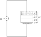
도 1은 본 발명의 제1 실시예에 따른 가스 감지 장치의 개략적인 단면도이다. 도 1을 참조하여 설명하면, 본 발명의 제1 실시예에 따른 가스 감지 장치(1A)는, 일측에 개방부(70)가 형성된 하우징(10), 하우징(10) 내에 배치되는 센서부(20), 센서부(20)를 센싱 온도로 가열하기 위한 히터부(50), 하우징(10)에 형성된 제1 개구(61)와 제2 개구(62)를 연결하는 연결 통로(60)를 포함한다.1 is a schematic cross-sectional view of a gas sensing device according to a first embodiment of the present invention. Referring to FIG. 1 , the gas sensing device 1A according to the first embodiment of the present invention includes a
하우징(10)은 중공의 튜브 형상으로 제공될 수 있다. 하우징(10)의 일측(도 1의 하방측)에는 개방부(70)가 형성되며, 개방부(70)는 감지 대상 가스가 인입되는 출입구를 제공할 수 있다. 가스 감지 장치(1A)가 측정 환경 내의 가스 농도 측정을 위해 사용되는 경우, 개방부(70)가 측정 환경과 연통되도록 하우징(10)이 설치될 수 있다. 예를 들어, 가스 감지 장치(1A)가 액체 중의 용존 가스 농도 측정을 위해 사용되는 경우, 가스 감지 장치(1A)의 하우징(10)은 개방부(70)가 액체 저장 용기와 연통되도록 설치되거나 개방부(70)가 형성된 일단이 액체 내에 잠기도록 설치될 수 있다. 액체로부터 증발한 용존 가스는 하우징(10)의 내부 공간(30)을 채우고, 센서부(20)는 이를 감지할 수 있다. The
센서부(20)는 하우징(10) 내에 배치되며, 하우징(10)의 길이 방향(도 1의 상하 방향)으로 양측 단부에서 이격된 위치에 배치될 수 있다. 예시적으로 도 1에 도시된 바와 같이, 센서부(20)는 하우징(10)의 개방부(70) 측 일단부로부터 길이 방향으로 d1만큼 이격되고, 하우징(10)의 타단부로부터 길이 방향으로 d2만큼 이격된 위치에 배치될 수 있다. 여기서 센서부(20)의 위치는 센서부(20)에 형성되는 감지전극의 위치일 수 있다.The
이처럼 센서부(20)를 하우징(10)의 단부로부터 길이 방향으로 이격된 위치에 배치하기 위해, 센서부(20)는 소정 길이의 프레임(22)의 일단(도 1의 하방측)에 고정된 상태로 하우징(10) 내에 설치될 수 있다. 프레임(22)은 하우징(10)보다 작은 직경의 튜브로 형성하여, 하우징(10) 내벽과 프레임(22) 사이에 폭 방향(도 1의 좌우 방향)으로 갭(g)이 형성되도록 할 수 있다. 프레임(22)의 일단부에는 센서부(20)가 고정되고, 프레임(22)의 타단부는 하우징(10)에 결합될 수 있다. 센서부(20)가 튜브 형상으로 제작되는 경우, 프레임(22)은 센서부(20)에 포함된 구성일 수 있다. 프레임(22)과 하우징(10)의 결합은 접착 결함, 나사 결합, 브레이징(brazing) 등 다양한 결합 수단이 사용될 수 있으며, 특정 결합 수단으로 한정되지 않는다. 한편, 프레임(22)과 하우징(10)의 결합은 가스 밀봉 결합일 수 있다. 이를 위해 프레임(22)과 하우징(10)의 결합 부분에 실링 물질(21)이 포함될 수 있다. 실링 물질(21)은 오링(O-ring) 등 탄성이 있는 고분자 물질로 형성될 수 있다. 또는, 프레임(22)과 하우징(10)이 접착 결합하는 경우, 실링 물질(21)은 접착 물질일 수 있다. As such, in order to arrange the
하우징(10)과 프레임(22)이 가스 밀봉되도록 결합되므로, 하우징(10)의 내부 공간(30)은 개방부(70)를 제외하면 외기로부터 차단된 밀폐 공간을 형성할 수 있다. 또는 프레임(22)과 하우징(10)의 결합이 가스 밀봉 결합이 아니더라도, 하우징(10)의 개방부(70)가 형성되지 않은 타측(도 1의 상방부)을 막힌 구조로 형성함으로써 내부 공간(30)을 밀폐 공간으로 형성하는 것도 가능하다.Since the
하우징(10)의 내부 공간(30)은 센서부(20)가 설치되는 위치에 의해 제1 내부 공간(31)과 제2 내부 공간(32)으로 구분될 수 있다. 제1 내부 공간(31)은 하우징(10)의 내부 공간(30) 중 센서부(20)와 개방부(70) 사이의 공간이고, 제2 내부 공간(32)은 하우징(10)의 내부 공간(30) 중 제1 내부 공간(31)을 제외한 공간일 수 있다. 도 1의 실시예에서 제1 내부 공간(31)은 센서부(20)의 아래쪽 내부 공간이고, 제2 내부 공간(32)은 센서부(20)의 위쪽 내부 공간, 즉 프레임(22)과 하우징(10) 내벽 사이의 갭(g)에 의해 형성되는 공간일 수 있다. 여기서 센서부(20)의 위쪽과 아래쪽은 센서부(20)에 형성되는 감지전극의 위치를 기준으로 구분될 수 있다.The
히터부(50)는 센서부(20)를 센싱 온도로 가열하기 위한 구성이다. 센싱 온도는 센서의 종류에 따라 달라질 수 있고, 300℃ 이상일 수 있다. 히터부(50)는 도 1에 예시적으로 도시한 것처럼 센서부(20)가 배치되는 위치의 하우징(10) 외부에 권취된 저항 가열식 히팅 코일을 포함하여 구성될 수 있으나, 이에 한정되지 않는 다양한 형태로 구비될 수 있다. 예를 들어, 히터부(50)는 하우징(10)의 내부에 배치될 수 있으며, 히팅 코일 대신 소정 기판에 인쇄된 히팅 패턴 형태로 구비될 수 있다. 또는 프레임(22)에 권취된 히팅 코일로 구비되거나, 프레임(22) 또는 센서부(20)에 내장된 형태로 구비될 수도 있다. 히터부(50)는 저항 가열식으로 한정되지 않으며, 가열 램프, LED 등 광조사식 히터부로 구비될 수도 있다.The
가스 감지 장치(1A)가 고온의 환경에서 사용되어 센서부(20)의 가열이 불필요한 경우, 히터부(50)는 생략될 수 있다. 예를 들어, 고온의 용탕 내 용존 가스 농도 측정을 위한 용도로 사용되는 경우, 가스 감지 장치(1A)는 히터부(50)를 포함하지 않을 수 있다.When the gas sensing device 1A is used in a high-temperature environment and heating of the
가스 감지 장치(1A)가 고압의 측정 환경에 연결되는 경우, 또는 액체 내 용존 가스 측정을 위해 개방부(70)가 액체 저장 용기에 연결되는 경우, 내부 공간(30)은 고압의 공간이 될 수 있다. 특히, 히터부(50)를 이용하여 센서부(20)를 고온으로 가열하면, 내부 공간(30)의 압력은 온도에 따라 더욱 증가할 수 있다. 이러한 압력의 증가는 감지 대상 가스가 센서부(20)로 이동하는 것을 어렵게 할 수 있다.When the gas sensing device 1A is connected to a high-pressure measurement environment, or when the
본 발명의 제1 실시예에 따른 가스 감지 장치(1A)는 이러한 문제를 해결하기 위해, 연결 통로(60)를 형성한다. 구체적으로는, 하우징(10)에 제1 개구(61) 및 제2 개구(62)를 형성하고, 제1 개구(61)와 제2 개구(62)를 연결 통로(60)로 연결한다. 제1 개구(61)는 제1 내부 공간(31)을 향해, 제2 개구(62)는 제2 내부 공간(32)을 향해 각각 개방되도록 하우징(10)에 형성될 수 있다. 도 1을 기준으로 설명하면, 제1 개구(61)는 센서부(20)보다 아래쪽에, 제2 개구(62)는 센서부(20)보다 위쪽에 형성될 수 있다. 여기서 센서부(20)의 위쪽과 아래쪽은 센서부(20)에 형성되는 감지전극의 위치를 기준으로 구분될 수 있다.In order to solve this problem, the gas sensing device 1A according to the first embodiment of the present invention forms a
이러한 구조에 의해, 제1 내부 공간(31)의 가스가 제1 개구(61), 연결 통로(60), 제2 개구(62), 제2 내부 공간(32)을 거쳐 다시 제1 내부 공간(30)으로 들어오는 순환 경로가 형성될 수 있다. 이러한 순환 경로를 형성함으로써, 센서부(20) 부근이 고압 상태가 되는 경우에도 개방부(70)를 통해 내부 공간(30)으로 인입된 감지 대상 가스가 센서부(20) 측으로 보다 쉽게 이동될 수 있다.With this structure, the gas of the first
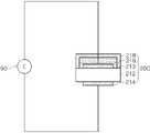
도 2는 본 발명의 제2 실시예에 따른 가스 감지 장치의 개략적인 단면도이다. 도 2를 참조하여 설명하면, 본 발명의 제2 실시예에 따른 가스 감지 장치(1B)는, 센서부(20)를 프레임을 사용하지 않고 하우징(10) 내에 배치시킨다는 점에서 제1 실시예에 따른 가스 감지 장치(1A)와 차이가 있다.2 is a schematic cross-sectional view of a gas sensing device according to a second embodiment of the present invention. Referring to FIG. 2 , the
본 발명의 제2 실시예에 따른 가스 감지 장치(1B)는, 일측에 개방부(70)가 형성된 하우징(10), 하우징(10) 내에 배치되는 센서부(20), 센서부(20)를 센싱 온도로 가열하기 위한 히터부(50), 하우징(10)에 형성된 제1 개구(61)와 제2 개구(62)를 연결하는 연결 통로(60)를 포함한다.The
하우징(10)은 일측(도 2의 하방측)이 개방된 중공의 튜브 형상으로 제공될 수 있다. 개방된 일측은 개방부(70)를 형성되며, 타측(도 2의 상방측)은 커버부(12)에 의해 막힌 구조일 수 있다. 이로 인해 하우징(10)의 내부 공간(30)은 개방부(70)를 제외하면 외기로부터 차단된 밀폐 공간을 형성할 수 있다. The
센서부(20)는 하우징(10)의 내부 공간(30)에 배치되며, 하우징(10)의 길이 방향(도 2의 상하 방향)으로 양측 단부에서 이격된 위치에 배치될 수 있다. 센서부(20)는 결합부(23)에 의해 하우징(10)의 내부 공간(30)에 결합될 수 있다. 결합부(23)는 접착 물질일 수 있으나, 이에 한정되지 않으며 센서부(20)를 하우징(10)의 내부 공간(30)에 배치시킬 수 있는 다양한 결합 수단이 사용될 수 있다.The
하우징(10)의 내부 공간(30)은 센서부(20)가 설치되는 위치에 의해 제1 내부 공간(31)과 제2 내부 공간(32)으로 구분될 수 있다. 제1 내부 공간(31)은 하우징(10)의 내부 공간(30) 중 센서부(20)와 개방부(70) 사이의 공간이고, 제2 내부 공간(32)은 하우징(10)의 내부 공간(30) 중 제1 내부 공간(31)을 제외한 공간일 수 있다. 도 2의 실시예에서 제1 내부 공간(31)은 센서부(20)의 아래쪽 내부 공간이고, 제2 내부 공간(32)은 센서부(20의 위쪽 내부 공간, 즉 커버부(12)와 센서부(20) 사이의 공간일 수 있다. 여기서 센서부(20)의 위쪽과 아래쪽은 센서부(20)에 형성되는 감지전극의 위치를 기준으로 구분될 수 있다.The
히터부(50)는 센서부(20)를 센싱 온도로 가열하기 위한 구성으로, 도 2에 예시적으로 도시한 것처럼 센서부(20)가 배치되는 위치의 하우징(10) 외부에 권취된 저항 가열식 히팅 코일을 포함하여 구성될 수 있으나 이에 한정되지 않는 다양한 형태로 구비될 수 있다. 예를 들어, 히터부(50)는 하우징(10)의 내부에 배치될 수 있으며, 히팅 코일 대신 소정 기판에 인쇄된 히팅 패턴 형태로 구비될 수 있다. 또는 센서부(20)에 내장된 형태로 구비될 수도 있다. 히터부(50)는 저항 가열식으로 한정되지 않으며, 가열 램프, LED 등 광조사식 히터부로 구비될 수도 있다.The
가스 감지 장치(1B)가 고온의 환경에서 사용되어 센서부(20)의 가열이 불필요한 경우, 히터부(50)는 생략될 수 있다. 예를 들어, 고온의 용탕 내 용존 가스 농도 측정을 위한 용도로 사용되는 경우, 가스 감지 장치(1B)는 히터부(50)를 포함하지 않을 수 있다.When the
하우징(10)에는 제1 개구(61) 및 제2 개구(62)가 형성되고, 제1 개구(61)와 제2 개구(62)는 연결 통로(60)로 연결된다. 제1 개구(61)는 제1 내부 공간(31)을 향해, 제2 개구(62)는 제2 내부 공간(32)을 향해 각각 개방되도록 하우징(10)에 형성될 수 있다. 도 2을 기준으로 설명하면, 제1 개구(61)는 센서부(20)보다 아래쪽에, 제2 개구(62)는 센서부(20)보다 위쪽에 형성될 수 있다. 여기서 센서부(20)의 위쪽과 아래쪽은 센서부(20)에 형성되는 감지전극의 위치를 기준으로 구분될 수 있다.A
센서부(20)는 결합부(23)에 의해 하우징(10)에 결합되나, 결합부(23) 및 센서부(20)에 의해 제1 내부 공간(31)과 제2 내부 공간(32)가 완전히 차단되지 않을 수 있다. 예를 들어, 결합부(23)는 센서부(20)의 테두리 중 일부 면적만 하우징(10) 내벽에 결합시키도록 구비되어, 하우징(10) 내벽과 센서부(20) 사이에 갭(g)이 형성되도록 할 수 있다. 도 3은 이를 설명하기 위한 도면으로, 도 2의 A-A선 단면도이다. 도 3을 참조하면, 결합부(23)는 센서부(20)의 테두리 중 4개소에만 형성되며, 결합부(23)가 형성되지 않은 부분에는 센서부(20)와 하우징(10) 내벽 사이에 소정의 갭(g)이 형성될 수 있다. 이로 인해 제1 내부 공간(31)과 제2 내부 공간(32) 사이의 가스 이동이 자유로울 수 있다. 도 3과 같은 결합 구조 외에도 결합부(23)를 통기성 물질로 형성하거나, 센서부(20)에 관통홀(미도시)을 형성하여 제1 내부 공간(31)과 제2 내부 공간(32)이 연통되도록 할 수 있다. The
이러한 구조에 의해, 제1 내부 공간(31)의 가스가 제1 개구(61), 연결 통로(60), 제2 개구(62), 제2 내부 공간(32)을 거쳐 다시 제1 내부 공간(31)으로 들어오는 순환 경로가 형성될 수 있다. 이러한 순환 경로를 형성함으로써, 센서부(20) 부근이 고압 상태가 되는 경우에도 개방부(70)를 통해 내부 공간(30)으로 인입된 감지 대상 가스가 센서부(20) 측으로 보다 쉽게 이동될 수 있다.With this structure, the gas of the first
본 발명의 실시예들에 따른 가스 감지 장치(1A, 1B)에 사용되는 센서부(20)는 측정 대상 가스, 적용 용도 등에 따라 다양한 가스 센서 소자가 사용될 수 있다. 측정 대상 가스에 따라 수소 센서 소자, 일산화탄소 센서 소자, 탄화수소 센서 소자 등이 센서부(20)로 사용될 수 있다. 또한, 그 형태에 따라 팰렛(pellet) 형태, 칩(chip) 형태, 튜브(tube) 형태 등 다양한 형태의 센서 소자가 센서부(20)로 사용될 수 있다. 또한 가스 감지 원리에 따라, 고체전해질(Solid Electrolyte)을 이용하여 가스 농도에 따른 기전력(EMF; Electromotive force) 변화를 측정하는 전기화학식(Electrochemical type) 센서 소자, 가스 농도에 따라 전기저항이 변하는 반도체 물질을 이용하는 반도체식(Semiconductor type) 센서 소자 등이 센서부(20)로 사용될 수 있다.In the
도 4 내지 도 6은 본 발명에서 센서부(20)로 사용 가능한 수소 센서 소자를 설명하기 위한 도면이다.4 to 6 are diagrams for explaining a hydrogen sensor element that can be used as the
도 4의 센서부(20A)는 본 발명의 제1 실시예(도 1)에 따른 수소 감지 장치에 사용하기에 특히 적합한 수소 센서 소자이다. 도 4를 참조하여 설명하면 센서부(20A)는, 산소이온전도체(211)와 수소이온전도체(212)가 접합된 이종 접합 구조의 고체전해질, 산소이온전도체(211)의 표면에 형성되어 있는 기준전극(213) 및 수소이온전도체(212)의 표면에 형성되어 있는 감지전극(214)을 포함할 수 있다. The
산소이온전도체(211)로는 지르코니아(ZrO2)에 여러 물질을 첨가하여 만든 안정화 지르코니아, 예를 들어 YSZ(Yttria stabilized zirconia), CSZ(calcium stabilized zirconia), MSZ(Magnesium stabilized zirconia)와 같은 고체전해질 또는 Gd2O3 등을 첨가한 CeO2계 화합물 등을 사용할 수 있다. 수소이온전도체(212)로는 ABO3형태의 페로브스카이트(perovskite) 구조를 갖는 물질의 B자리에 여러 물질을 치환한 물질, 예를 들어 CaZr0.9In0.1O3-x 등과 같은 CaZrO3계, SrZr0.95Y0.05O3-x 등과 같은 SrZrO3계, SrCe0.95Yb0.05O3-x 등과 같은 SrCeO3계, BaCe0.9Nd0.1O3-x 등과 같은 BaCeO3계, BaTiO3, SrTiO3, PbTiO3 등과 같은 Ti계 화합물을 사용할 수 있다.As the
또한, 기준전극(213) 및 감지전극(214)은 백금(Pt) 등의 귀금속으로 형성할 수 있다.In addition, the
기준전극(213)과 감지전극(214)은 리드선을 통해 측정부(90)에 전기적으로 연결되어, 기전력 측정에 의해 수소 가스 농도가 측정될 수 있다. 기준전극(213)과 감지전극(214) 사이에서 측정되는 기전력(E)은 기준전극(213) 측의 산소분압(PO2) 및 감지전극(214) 측의 수소분압(PH2)과 다음과 같은 관계가 성립한다.The
E = Eo +A·log PH2 +(A/2)·logPO2 -------- (1)E = Eo +A log P H2 +(A/2) logP O2 -------- (1)
위 식에서 Eo와 A는 온도에만 의존하는 상수이므로, 기준전극(213) 측의 산소분압(PO2)을 알면 기전력(E) 측정에 의해 감지전극(214) 측의 수소분압(PH2)을 결정할 수 있다.In the above equation, Eo and A are constants that depend only on temperature, so if you know the oxygen partial pressure (P O2 ) on the
기준전극(213) 측의 산소분압(PO2)은 기준전극(214)을 대기에 노출시킴으로써 고정시킬 수 있다. 즉, 도 1과 도 4를 함께 참조하면, 센서부(20A)에 고정된 프레임(22)을 실링 물질(21)을 이용하여 하우징(10)에 가스 밀봉되도록 결합시키고 기준전극(213)은 대기에 노출되도록 가스 감지 장치(1A)를 구성함으로써, 기준전극(213) 측의 산소분압(PO2)은 공기 중의 산소분압인 0.21기압으로 고정시킬 수 있다. 따라서, 기준전극(213)과 감지전극(214) 사이의 기전력(E)을 측정함으로써 식(1)에 의해 감지전극(213) 측의 수소분압(PH2)을 산출할 수 있다. The oxygen partial pressure P O2 on the side of the
도 5의 센서부(20B)는 기준전극(213)을 대기에 노출하여 산소분압(PO2)을 고정시키는 대신, 기준전극(213)을 산소분압 고정용 기준물질(215)로 덮어 산소분압(PO2)을 열역학적으로 고정시킨 구조라는 점에서 도 4의 센서부(20A)와 차이가 있다. The
산소분압 고정용 기준물질(215)로는 Cu/CuO, Ni/NiO, Ti/TiO2, Fe/FeO, Cr/Cr2O3, Mo/MoO 등 금속과 금속산화물의 혼합체, 또는 Cu2O/CuO, FeO/Fe2O3 등 산화 정도가 다른 금속 산화물의 혼합체를 사용할 수 있으며, 이러한 산소분압 고정용 기준물질(215)로 기준전극(213)을 덮어주게 되면 기준전극(213) 측의 산소 분압을 열역학적으로 고정시켜 줄 수 있다. 즉, 기준전극(213) 측의 산소 분압이 외부 공기에 의해 결정되는 대신 산소분압 고정용 기준물질(215)에 의해 결정되게 되며, 도 4를 참조하여 설명한 것과 마찬가지로 기준전극(213)과 감지전극(214) 사이의 기전력을 측정하여 식 (1)에 의해 감지전극(214) 측의 수소분압을 산출할 수 있다.As the
도 5의 센서부(20B)는 본 발명의 제1 실시예에 따른 가스 감지 장치(1A)와 제2 실시예에 따른 가스 감지 장치(1B) 중 어느 것에도 적합할 수 있다. 산소분압 고정용 기준물질(215)이 외기 또는 내부 공간(30) 내의 가스 분위기에 영향 받는 것을 방지하기 위해, 산소분압 고정용 기준물질(215)을 외기와 차단하기 위한 밀봉 덮개(218)를 추가로 구비할 수도 있다. 밀봉 덮개(218)는 외기의 침투를 방지할 수 있는 치밀한 세라믹 물질 등으로 형성할 수 있으며, 외기의 영향이 미미한 경우 생략할 수 있다.The
도 6의 센서부(20C)는 수소이온전도체(212), 수소이온전도체(212)의 양면에 각각 형성되어 있는 기준전극(213) 및 감지전극(214), 기준전극(213)을 덮는 수소분압 고정용 기준물질(216)을 포함하여 형성된다. 즉, 도 5의 센서부(20B)와 비교하면, 산소이온전도체가 없고, 기준전극(213)를 산소분압 고정용 기준물질 대신 수소분압 고정용 기준물질(216)로 덮는다는 차이가 있다.The sensor unit 20C of FIG. 6 has the
수소분압 고정용 기준물질(216)로는 Ti/TiH2, Zr/ZrH2, Ca/CaH2, Nd/NdH2 등 금속과 금속수화물의 혼합상을 사용할 수 있으며, 이에 의해 기준전극(213) 측 수소분압(P2, H2)을 열역학적으로 고정시킬 수 있다.A mixed phase of a metal and a metal hydrate, such as Ti/TiH 2 , Zr/ZrH 2 , Ca/CaH 2 , and Nd/NdH 2 , may be used as the
도 6의 센서부(20C)도 기준전극(213)과 감지전극(214) 사이의 기전력(E)을 측정하여 다음의 네른스트(Nernst) 식에 의해 감지전극(214) 측의 수소분압(P1, H2)을 결정할 수 있다.The sensor unit 20C of FIG. 6 also measures the electromotive force (E) between the
E = -(RT/2F)ln(P2, H2/P1, H2) ---------- (2)E = -(RT/2F)ln(P 2, H2 /P 1, H2 ) ---------- (2)
위 식 (2)에서 R은 기체상수, F는 페러데이 상수, T는 센싱 온도로서 모두 상수이며, 기준전극(213)의 수소분압(P2, H2)도 수소분압 고정용 기준물질(216)에 의해 결정되는 값이므로, 측정되는 기전력(E) 값으로부터 감지전극(214) 측의 수소분압(P1, H2)이 산출된다.In Equation ( 2 ) above, R is a gas constant, F is a Faraday constant, and T is a sensing temperature. Since it is a value determined by
도 6의 센서부(20C)는 본 발명의 제1 실시예에 따른 가스 감지 장치(1A)와 제2 실시예에 따른 가스 감지 장치(1B) 중 어느 것에도 적합할 수 있다. 수소분압 고정용 기준물질(216)이 외기 또는 내부 공간(30) 내의 가스 분위기에 영향 받는 것을 방지하기 위해, 수소분압 고정용 기준물질(216)을 외기와 차단하기 위한 밀봉 덮개(218)를 추가로 구비할 수도 있다.The sensor unit 20C of FIG. 6 may be suitable for either the gas sensing device 1A according to the first embodiment or the
본 발명의 실시예들에 따른 가스 감지 장치는 액체 내의 용존 가스 농도 측정을 위해 사용될 수 있다. A gas sensing device according to embodiments of the present invention may be used to measure a dissolved gas concentration in a liquid.
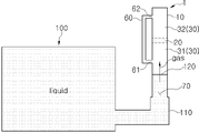
도 7은 액체 저장 용기(100)에 수용된 액체 내의 용존 가스 농도 측정을 위해 본 발명의 가스 감지 장치를 사용하는 사용예이다. 도 7에는 가스 감지 장치(1)의 구조를 주요부 위주로 간략하게만 도시하나, 본 발명의 제1 실시예에 따른 가스 감지 장치(1A) 또는 제2 실시예에 따른 가스 감지 장치(1B)가 모두 사용될 수 있다.7 is an example of use of the gas sensing device of the present invention for measuring the concentration of a dissolved gas in a liquid contained in the
도 7을 참조하면, 본 발명에 따른 가스 감지 장치(1)는 접속구(110)를 통해 액체 저장 용기(100)에 결합될 수 있다. 접속구(110)는 도시된 것처럼 액체 저장 용기(100)의 측면에 형성될 수도 있으나 이에 한정되지 않으며, 액체 저장 용기(100)의 상면이나 하면 등 다양한 위치에 형성될 수 있다. 가스 감지 장치(1)를 접속구(110)를 통해 액체 저장 용기(100)에 결합하면 액체 저장 용기(100) 내부와 가스 감지 장치(1)의 내부 공간(30)은 서로 연통되며, 액체 저장 용기(100)에 수용된 액체 내의 용존 가스가 증발하여 내부 공간(30)으로 이동될 수 있다.Referring to FIG. 7 , the
일반적으로 액체에 대한 기체의 용해도는 식 (3)의 시버트(Siebert)의 법칙에 따른다.In general, the solubility of gas in liquid follows Siebert's law in Equation (3).
C = k·Pgas ---- (3)C = k P gas ---- (3)
C는 액체 내에 용해되는 용존 가스의 농도, k는 가스 종류, 온도 등에 의존하는 상수, Pgas는 액체와 접해 있는 공간 내에서의 가스 분압이다. 즉, 용존 가스 농도(C)와 액체와 접해 있는 공간 내에서의 가스 분압(Pgas)은 비례하며, 액체로부터 공간 내로 증발하는 가스의 증발 속도와 공간 내부의 가스가 액체에 용해되는 속도가 같을 때 평형 상태에 도달하게 된다. C is the concentration of dissolved gas in the liquid, k is a constant depending on the gas type and temperature, and P gas is the gas partial pressure in the space in contact with the liquid. That is, the dissolved gas concentration (C) and the gas partial pressure (P gas ) in the space in contact with the liquid are proportional, and the evaporation rate of the gas evaporating from the liquid into the space and the dissolution rate of the gas in the space are the same. when equilibrium is reached.
이러한 원리에 따르면, 도 7과 같이 본 발명의 가스 감지 장치(1)를 액체 저장 용기(100)와 연결하면, 액체 저장 용기(100)에 수용된 액체 내의 용존 가스가 가스 감지 장치(1)의 내부 공간(30) 내로 증발하여 평형을 이루게 된다. 따라서, 센서부(20)를 이용하여 내부 공간(30) 내의 가스 농도(가스 분압)를 측정하는 것에 의해 액체 내의 용존 가스 농도를 알 수 있다.According to this principle, when the
한편, 액체 저장 용기(100) 내의 액체의 압력에 따라 액체 저장 용기(100)에 연결된 가스 감지 장치(1)의 내부 공간(30) 내부 압력이 증가할 수 있다. 즉, 액체 저장 용기(100)에 수용된 액체가 접속구(110)를 통해 가스 감지 장치(1)의 내부 공간(30)으로 이동하여 액면(120)이 가스 감지 장치(1)의 내부 공간(30) 내에 형성될 수 있다. 이로 인해, 가스 감지 장치(1)의 내부 공간(30) 내의 가스 부피는 내부 공간(30) 내부 압력이 액체의 압력과 동일해질 때까지 수축할 수 있다. Meanwhile, the internal pressure of the
이러한 내부 공간(30)의 내부 압력 증가는 액체로부터 증발된 가스가 센서부(20)의 감지전극(214)까지 이동하는 것을 어렵게 할 수 있다. 특히 히터부(50)를 이용하여 센서부(20)를 센싱 온도까지 가열하는 것에 의해 내부 공간(30)의 내부 압력은 더욱 증가하고, 그로 인해 용존 가스가 감지전극(214)까지 이동하는 것은 더욱 어려워 질 수 있다. 이는 용존 가스의 농도를 신속하고 정확하게 측정하는데 장애 요소가 될 수 있다. This increase in the internal pressure of the
그러나 본 발명에 따른 가스 감지 장치(1)는 제1 내부 공간(31) 및 제2 내부 공간(32)을 향해 각각 개방된 제1 개구(61)와 제2 개구(62)를 연결하는 연결 통로(60)를 따라 내부 공간(30) 내의 가스가 순환할 수 있으므로, 내부 공간(30)이 고압 상태가 되는 경우에도 개방부(70)를 통해 인입되는 가스가 감지전극(214)까지 원활하게 이동할 수 있다. 이로 인해 용존 가스 농도를 신속하고 정확히 측정하는 것이 가능해진다.However, in the
도 7에서 액면(120)은 제1 개구(61)보다 아래에 형성되는 것이 바람직하나, 제1 개구(61)보다 상부에 형성되어도 무방하다. 즉, 제1 개구(61)가 액체 내에 잠기더라도, 액체로부터 증발되는 용존 가스는 연결 통로(60)를 통해 제2 개구(62) 쪽으로 이동될 수 있다. 다만, 액면(120)이 센서부(20)보다는 아래에 형성되어야 하므로, 액체 압력 등 사용 환경을 고려하여 하우징(10)의 길이 및/또는 접속구(110)의 높이를 설계하는 것이 바람직하다. 선택적으로, 액체에 의해 센서부(20)가 오염되는 것을 방지하기 위해 접속구(110) 또는 제1 내부 공간(31)에 가스 투과 필터를 배치할 수 있다. 가스 투과 필터는 액체는 투과하지 못하고 가스만 투과할 수 있는 구성이면 그 재질이나 형태를 한정하지 않으며, 예를 들어 흑연, 세라믹 파우더, PTFE막 등을 포함하여 제조된 가스 투과막일 수 있다.In FIG. 7 , the
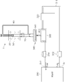
도 8은 액체 저장 용기(300)에 수용된 액체 내의 용존 가스 농도 측정을 위해 본 발명의 가스 감지 장치를 사용하는 다른 사용예이다. 액체 저장 용기(300)는 변압기일 수 있고, 액체 저장 용기(300)에 수용된 액체는 변압기의 절연유일 수 있다.8 is another example of use of the gas sensing device of the present invention for measuring a dissolved gas concentration in a liquid contained in a
도 8을 참조하여 설명하면, 액체 저장 용기(300)에는 액체 순환을 위한 순환 배관(310)이 연결된다. 순환 배관(310)에는 밸브(313, 314) 및 순환 모터(320)가 구비되고, 밸브(313, 314)를 개방한 상태에서 순환 모터(320)를 구동시킴으로써 도면에 화살표로 표시된 방향으로 액체가 순환하는 순환 경로가 형성된다.Referring to FIG. 8 , a
순환 경로 상에는 측정 탱크(330)가 구비되어, 순환 배관(310)을 따라 순환되는 액체가 측정 탱크(330)를 거치도록 구성된다. 즉, 순환 탱크(330) 내에는 순환되는 액체가 임시적으로 저장될 수 있다. A
본 발명에 따른 가스 감지 장치(1)는 순환 탱크(330)에 접속구(340)를 통해 결합될 수 있다. 이로 인해 측정 탱크(330) 내의 액체에서 증발된 용존 가스가 가스 감지 장치(1)의 내부 공간(30)으로 이동될 수 있다. 액체가 가스 감지 장치(1)로 이동되는 것을 방지하기 위하여 접속구(340)에 가스 투과 필터(341)를 구비할 수 있다. 가스 감지 장치(1)는 본 발명의 제1 실시예에 따른 가스 감지 장치(1A) 및 제2 실시예에 따른 가스 감지 장치(1B)가 모두 사용될 수 있다.The
도 9는 본 발명의 제1 실시예에 다른 가스 감지 장치(1A)를 수소 농도가 4%로 일정하게 유지되는 측정 환경에 연결한 후 센서부(20)의 기전력(E)을 측정한 결과이다. 이때 센서부(20)로는 도 4의 수소 센서 소자를 사용하였다. 즉, 센서부(20)는 산소이온전도체(211)와 수소이온전도체(212)가 접합되고, 산소이온전도체(211)에 기준전극(213)을, 수소이온전도체(214)에 감지전극(214)을 형성한 전기화학식 수소 센서를 사용하였다. 산소이온전도체(211) 및 수소이온전도체(212)로는 각각 YSZ(Yttria stabilized zirconia)와 CaZr0.9In0.1O3-x를 사용하였으며, 기준전극(213) 및 감지전극(214)은 백금(Pt)으로 형성하였다.9 is a result of measuring the electromotive force (E) of the
센서부(20)에 열전대(Thermocouple)를 연결하여 온도를 측정하면서 히터부(50)를 이용하여 센서부(20)를 가열하였으며, 시간에 따라 온도 및 기전력의 변화를 측정하였다. 도 9에서 확인되는 바와 같이, 온도가 상승함에 따라 기전력이 지속적으로 상승하며, 약 300℃ 이상의 온도에서 약 1.1V의 안정적인 기전력이 측정되었다. The
도 10은 비교를 위해 연결 통로(60)를 형성하지 않은 가스 감지 장치를 이용하여 동일한 조건에서 측정한 결과이다. 도 10에서 사용한 가스 감지 장치는 연결 통로(60) 및 제1, 2 개구(61, 62)가 없다는 점을 제외하면 도 9에서 사용한 가스 감지 장치와 동일하였다. 도 10을 참조하면, 온도가 상승함에 따라 기전력이 증가하는 경향이 나타나기는 하지만, 도 9의 결과와 비교하여 기전력 값이 매우 낮고 불안정하게 측정됨을 확인할 수 있다.10 is a result of measurement under the same conditions using a gas sensing device that does not form the
이상의 결과로부터, 본 발명의 가스 감지 장치를 사용할 경우 신속하고 정확한 가스 농도 측정이 가능함을 알 수 있다. From the above results, it can be seen that when the gas sensing device of the present invention is used, it is possible to quickly and accurately measure the gas concentration.
이상 한정된 실시예 및 도면을 참조하여 설명하였으나, 본 발명의 기술사상의 범위 내에서 다양한 변형 실시가 가능하다는 점은 통상의 기술자에게 자명할 것이다. 예를 들어, 본 발명의 가스 감지 장치에 포함되는 연결 통로는 복수 개가 구비될 수 있다. 따라서, 본 발명의 보호범위는 특허청구범위의 기재 및 그 균등 범위에 의해 정해져야 한다.Although described above with reference to the limited embodiments and drawings, it will be apparent to those skilled in the art that various modifications are possible within the scope of the technical idea of the present invention. For example, a plurality of connection passages included in the gas sensing device of the present invention may be provided. Therefore, the protection scope of the present invention should be defined by the description of the claims and their equivalents.
Claims (13)
상기 하우징의 내부 공간에 배치되는 센서부; 및
상기 하우징의 내부 공간을 향하여 개방되도록 하우징에 형성된 제1 개구 및 제2 개구를 연결하는 연결 통로;
를 포함하는 것을 특징으로 하는 가스 감지 장치.a housing including an opening through which a sensing target gas is introduced into the interior space;
a sensor unit disposed in the inner space of the housing; and
a connecting passage connecting the first opening and the second opening formed in the housing to be opened toward the inner space of the housing;
Gas sensing device comprising a.
상기 센서부를 센싱 온도로 가열하기 위한 히터부를 더 포함하는 것을 특징으로 하는 가스 감지 장치.According to claim 1,
Gas sensing device, characterized in that it further comprises a heater for heating the sensor unit to the sensing temperature.
상기 하우징의 내부 공간은, 상기 개방부를 통해서만 외기와 연통되는 것을 특징으로 하는 가스 감지 장치.According to claim 1,
The gas sensing device, characterized in that the inner space of the housing communicates with the outside air only through the opening.
상기 하우징의 내부 공간은,
상기 센서부와 상기 개방부 사이의 제1 내부 공간과, 상기 제1 내부 공간을 제외한 내부 공간인 제2 내부 공간을 포함하여 구성되고,
상기 제1 개구는 제1 내부 공간을 향해 개방되고, 상기 제2 개구는 제2 내부 공간을 향해 개방된 것을 특징으로 하는 가스 감지 장치.According to claim 1,
The inner space of the housing,
It is configured to include a first internal space between the sensor part and the open part, and a second internal space that is an internal space excluding the first internal space,
The gas sensing device of claim 1, wherein the first opening opens toward the first interior space, and the second opening opens toward the second interior space.
상기 하우징은 길이 방향 일단부에 상기 개방부가 형성된 중공의 튜브 형상이고,
상기 센서부는 상기 하우징의 내경보다 작은 외경을 갖는 프레임의 길이 방향 일단부에 고정된 상태로 상기 하우징의 내부 공간에 배치되고,
상기 프레임의 길이 방향 타단부는 상기 하우징에 가스 밀봉되도록 고정되는 것을 특징으로 하는 가스 감지 장치. 5. The method of claim 4,
The housing has a hollow tube shape in which the opening is formed at one end in the longitudinal direction,
The sensor unit is disposed in the inner space of the housing while being fixed to one end in the longitudinal direction of the frame having an outer diameter smaller than the inner diameter of the housing,
The other longitudinal end of the frame is gas-sealed and fixed to the housing.
상기 하우징의 내벽과 상기 프레임 사이의 공간이 상기 제2 내부 공간을 형성하고,
상기 제1 내부 공간, 제1 개구, 연결 통로, 제2 개구, 제2 내부 공간을 순환하는 순환 경로가 형성되는 것을 특징으로 하는 가스 감지 장치.6. The method of claim 5,
A space between the inner wall of the housing and the frame forms the second inner space,
and a circulation path circulating through the first inner space, the first opening, the connecting passage, the second opening, and the second inner space is formed.
상기 하우징은 길이 방향 일단부에 상기 개방부가 형성된 중공의 튜브 형상이고,
상기 하우징의 길이 방향 타단부는 커버부에 의해 막혀 있고,
상기 센서부는 상기 하우징의 내벽에 결합된 상태로 상기 하우징의 내부 공간에 배치되는 것을 특징으로 하는 가스 감지 장치.5. The method of claim 4,
The housing has a hollow tube shape in which the opening is formed at one end in the longitudinal direction,
The other longitudinal end of the housing is blocked by a cover,
The sensor unit is a gas sensing device, characterized in that it is disposed in the inner space of the housing in a state coupled to the inner wall of the housing.
상기 하우징의 내벽과 상기 센서부 사이에는 갭이 존재하고,
상기 제1 내부 공간, 제1 개구, 연결 통로, 제2 개구, 제2 내부 공간을 순환하는 순환 경로가 형성되는 것을 특징으로 하는 가스 감지 장치.8. The method of claim 7,
A gap exists between the inner wall of the housing and the sensor unit,
and a circulation path circulating through the first inner space, the first opening, the connecting passage, the second opening, and the second inner space is formed.
상기 센서부는 수소 센서 소자를 포함하는 것을 특징으로 하는 가스 감지 장치.According to claim 1,
The sensor unit gas sensing device, characterized in that it comprises a hydrogen sensor element.
상기 수소 센서 소자는,
고체전해질;
상기 고체전해질의 상기 개방부 방향의 일면에 형성된 감지전극; 및
상기 고체전해질의 타면에 형성되는 기준전극;
을 포함하고,
상기 제1 개구는 상기 감지전극과 상기 개방부 사이에 위치하는 것을 특징으로 하는 가스 감지 장치.10. The method of claim 9,
The hydrogen sensor element,
solid electrolyte;
a sensing electrode formed on one surface of the solid electrolyte in the direction of the opening; and
a reference electrode formed on the other surface of the solid electrolyte;
including,
The first opening is positioned between the sensing electrode and the opening.
상기 하우징의 길이 방향 상단부 및 하단부로부터 모두 소정 거리 이격된 위치의 내부 공간에 배치되며, 상기 개방부에 대향하도록 형성된 감지전극을 포함하는 센서부;
상기 센서부를 센싱 온도로 가열하도록 구비되는 히터부;
를 포함하고,
상기 하우징의 내부 공간은 상기 센서부의 감지전극을 기준으로 하방의 제1 내부 공간과 상방의 제2 내부 공간을 포함하여 구성되고,
상기 하우징에는 상기 제1 내부 공간을 향해 개방되도록 형성된 제1 개구와, 상기 제2 내부 공간을 향해 개방되도록 형성된 제2 개구가 형성되고,
상기 제1 개구와 제2 개구를 연결하는 연결 통로가 구비되어, 상기 개방부를 통해 인입된 감지 대상 가스가 상기 제1 내부 공간, 제1 개구, 연결 통로, 제2 개구, 제2 내부 공간으로 순환하는 순환 경로가 형성되는 것을 특징으로 하는 가스 감지 장치.A housing having a hollow tube shape including an inner space, the housing being opened toward the inner space at a lower end in a longitudinal direction and having an opening formed therein so that a gas to be sensed is introduced;
a sensor unit disposed in an inner space spaced apart by a predetermined distance from both upper and lower ends of the housing in the longitudinal direction, the sensor unit including a sensing electrode formed to face the opening;
a heater unit provided to heat the sensor unit to a sensing temperature;
including,
The inner space of the housing is configured to include a lower first inner space and an upper second inner space with respect to the sensing electrode of the sensor unit,
A first opening formed to open toward the first inner space and a second opening formed to open toward the second inner space are formed in the housing;
A connection passage connecting the first opening and the second opening is provided, and the sensing target gas introduced through the opening is circulated to the first internal space, the first opening, the connection passage, the second opening, and the second internal space. Gas sensing device, characterized in that the circulation path is formed.
상기 센서부는 상기 하우징의 내경보다 작은 직경의 중공의 튜브 형상의 프레임의 하단부에 고정된 상태로 상기 내부 공간에 배치되고,
상기 프레임의 내부는 상기 하우징의 내부 공간과 격리된 상태로 외기에 노출되고,
상기 센서부는 상기 프레임의 내부를 통하여 외기에 노출되는 기준전극을 더 포함하는 것을 특징으로 하는 가스 감지 장치.12. The method of claim 11,
The sensor unit is disposed in the inner space while being fixed to the lower end of the hollow tube-shaped frame having a diameter smaller than the inner diameter of the housing,
The inside of the frame is exposed to the outside air in a state isolated from the inner space of the housing,
The sensor unit gas sensing device, characterized in that it further comprises a reference electrode exposed to outside air through the inside of the frame.
상기 센서부는 테두리 일부 면적이 소정의 결합부를 통해 상기 하우징의 내벽에 결합되는 방식으로 상기 내부 공간에 배치되고,
상기 결합부가 형성되지 않은 부분에서는 상기 센서부와 상기 하우징 내벽 사이에 갭이 형성되어, 상기 갭을 통해 제1 내부 공간과 제2 내부 공간이 연통되는 것을 특징으로 하는 가스 감지 장치.12. The method of claim 11,
The sensor part is disposed in the inner space in such a way that a portion of the edge area is coupled to the inner wall of the housing through a predetermined coupling part,
In a portion where the coupling part is not formed, a gap is formed between the sensor part and the inner wall of the housing, and the first internal space and the second internal space communicate with each other through the gap.
Applications Claiming Priority (3)
| Application Number | Priority Date | Filing Date | Title |
|---|---|---|---|
| KR1020200056689 | 2020-05-12 | ||
| KR20200056689 | 2020-05-12 | ||
| PCT/KR2021/003369 WO2021230484A1 (en) | 2020-05-12 | 2021-03-18 | Gas sensing device including housing having connection passage |
Publications (1)
| Publication Number | Publication Date |
|---|---|
| KR20220128421A true KR20220128421A (en) | 2022-09-20 |
Family
ID=78524841
Family Applications (1)
| Application Number | Title | Priority Date | Filing Date |
|---|---|---|---|
| KR1020227028286A KR20220128421A (en) | 2020-05-12 | 2021-03-18 | Gas sensing device including a housing having a connection passage formed therein |
Country Status (6)
| Country | Link |
|---|---|
| US (1) | US20230146123A1 (en) |
| EP (1) | EP4113096A4 (en) |
| JP (1) | JP7361430B2 (en) |
| KR (1) | KR20220128421A (en) |
| CN (1) | CN115135983A (en) |
| WO (1) | WO2021230484A1 (en) |
Family Cites Families (16)
| Publication number | Priority date | Publication date | Assignee | Title |
|---|---|---|---|---|
| JPH0348518Y2 (en) * | 1985-11-08 | 1991-10-16 | ||
| JP4251970B2 (en) * | 2003-01-31 | 2009-04-08 | 日本特殊陶業株式会社 | Gas sensor |
| JP5416686B2 (en) * | 2010-12-13 | 2014-02-12 | 日本特殊陶業株式会社 | Multi gas sensor |
| KR101464729B1 (en) * | 2012-10-29 | 2014-11-27 | 한국과학기술원 | Packaging structure of the gas sensor for the use in the molten metal |
| CN203299045U (en) * | 2013-04-27 | 2013-11-20 | 深圳职业技术学院 | Detection device for diesel automobile exhaust |
| JP5910683B2 (en) * | 2013-08-30 | 2016-04-27 | 株式会社デンソー | Gas concentration detector |
| KR101581941B1 (en) * | 2014-01-17 | 2016-01-04 | 한국과학기술원 | The hydrogen sensor device for measurement of dissolved in the liquid |
| KR20160011722A (en) | 2014-07-22 | 2016-02-02 | 한국과학기술원 | The hydrogen sensor device for measurement of dissolved in the liquid and the measurement method using the same |
| KR101512189B1 (en) | 2013-09-12 | 2015-04-13 | 한국과학기술원 | The hydrogen sensor device for measurement of dissolved in the oil and the method for sensing oil degradation using the same |
| EP3045900B1 (en) * | 2013-09-12 | 2022-01-19 | Korea Advanced Institute Of Science And Technology | Hydrogen sensor element for measuring concentration of hydrogen gas dissolved in liquid and method for measuring concentration of hydrogen gas using same |
| JP5942065B1 (en) * | 2015-08-03 | 2016-06-29 | 株式会社ジェイ・イー・ティ | Sensor unit and airtightness inspection device |
| JP6369496B2 (en) * | 2015-09-17 | 2018-08-08 | 株式会社デンソー | Gas sensor |
| JP2017067538A (en) * | 2015-09-29 | 2017-04-06 | Toto株式会社 | Biological information measurement system |
| KR20180004490A (en) * | 2016-07-04 | 2018-01-12 | 프리시젼센서시스템 주식회사 | Electrochemical type sensor module using reference gas |
| CN111656177B (en) * | 2018-02-06 | 2022-12-30 | 日本碍子株式会社 | Gas sensor |
| KR20200056689A (en) | 2018-11-15 | 2020-05-25 | 주식회사 화진 | Gradation Method of Magnesium member and Magnesium Product with a Gradation Layer |
-
2021
- 2021-03-18 JP JP2022549754A patent/JP7361430B2/en active Active
- 2021-03-18 WO PCT/KR2021/003369 patent/WO2021230484A1/en unknown
- 2021-03-18 CN CN202180016113.9A patent/CN115135983A/en active Pending
- 2021-03-18 EP EP21803815.6A patent/EP4113096A4/en active Pending
- 2021-03-18 KR KR1020227028286A patent/KR20220128421A/en unknown
- 2021-03-18 US US17/916,721 patent/US20230146123A1/en active Pending
Also Published As
| Publication number | Publication date |
|---|---|
| EP4113096A1 (en) | 2023-01-04 |
| CN115135983A (en) | 2022-09-30 |
| JP7361430B2 (en) | 2023-10-16 |
| EP4113096A4 (en) | 2024-04-03 |
| WO2021230484A1 (en) | 2021-11-18 |
| US20230146123A1 (en) | 2023-05-11 |
| JP2023515457A (en) | 2023-04-13 |
Similar Documents
| Publication | Publication Date | Title |
|---|---|---|
| JP6165343B2 (en) | Hydrogen sensor element for measuring dissolved hydrogen gas concentration in liquid and method for measuring hydrogen gas concentration using the same | |
| Park et al. | Solid-state electrochemical gas sensors | |
| Pasierb et al. | Solid-state potentiometric gas sensors—current status and future trends | |
| US4902400A (en) | Gas sensing element | |
| KR101512189B1 (en) | The hydrogen sensor device for measurement of dissolved in the oil and the method for sensing oil degradation using the same | |
| US5879526A (en) | Electrochemical measuring sensor for determining nitrogen oxides in gas mixtures | |
| Demin et al. | Sensors based on solid oxide electrolytes | |
| KR101581941B1 (en) | The hydrogen sensor device for measurement of dissolved in the liquid | |
| KR20220128421A (en) | Gas sensing device including a housing having a connection passage formed therein | |
| JP6494023B2 (en) | Gas sensor and gas sensor manufacturing method | |
| US10921299B2 (en) | Analytical device for constituents of a sample | |
| JP6149008B2 (en) | Hydrogen sensor | |
| JP2005338091A (en) | Sensor element for gas measurement sensor | |
| KR20160011722A (en) | The hydrogen sensor device for measurement of dissolved in the liquid and the measurement method using the same | |
| KR100891561B1 (en) | Methode for fabricating novel design gas sensors for hydrogen and oxygen | |
| Etsell et al. | Non-isothermal probe for continuous measurement of oxygen in steel | |
| KR20180004490A (en) | Electrochemical type sensor module using reference gas | |
| Porat et al. | Double‐Solid Electrochemical Cell for Controlling Oxygen Concentration in Oxides | |
| KR102654353B1 (en) | Hetero-juction solid electroyte hydrogen sensor comprising gold reference electrode | |
| JP2016521855A (en) | Gas sensor for measuring a plurality of different gases and associated manufacturing method | |
| JP2008224637A (en) | Gas sensor and its manufacturing method | |
| KR102315252B1 (en) | Hydrogen gas sensor | |
| Adachi et al. | Chemical sensors | |
| Ghetta et al. | Control and monitoring of oxygen content in molten metals. Application to lead and lead-bismuth melts | |
| Yoon | A Study of Interface Reaction of Lithium Lanthanum Titanate-Lithium Carbonate and Its Effect on Potentiometric Carbon Dioxide Gas Sensors |