KR20220123413A - Test system with column braces - Google Patents
Test system with column braces Download PDFInfo
- Publication number
- KR20220123413A KR20220123413A KR1020227024355A KR20227024355A KR20220123413A KR 20220123413 A KR20220123413 A KR 20220123413A KR 1020227024355 A KR1020227024355 A KR 1020227024355A KR 20227024355 A KR20227024355 A KR 20227024355A KR 20220123413 A KR20220123413 A KR 20220123413A
- Authority
- KR
- South Korea
- Prior art keywords
- base
- columns
- brace
- column
- crosshead
- Prior art date
Links
Images


Classifications
-
- G—PHYSICS
- G01—MEASURING; TESTING
- G01N—INVESTIGATING OR ANALYSING MATERIALS BY DETERMINING THEIR CHEMICAL OR PHYSICAL PROPERTIES
- G01N3/00—Investigating strength properties of solid materials by application of mechanical stress
- G01N3/32—Investigating strength properties of solid materials by application of mechanical stress by applying repeated or pulsating forces
-
- G—PHYSICS
- G01—MEASURING; TESTING
- G01N—INVESTIGATING OR ANALYSING MATERIALS BY DETERMINING THEIR CHEMICAL OR PHYSICAL PROPERTIES
- G01N3/00—Investigating strength properties of solid materials by application of mechanical stress
- G01N3/02—Details
-
- G—PHYSICS
- G01—MEASURING; TESTING
- G01N—INVESTIGATING OR ANALYSING MATERIALS BY DETERMINING THEIR CHEMICAL OR PHYSICAL PROPERTIES
- G01N3/00—Investigating strength properties of solid materials by application of mechanical stress
- G01N3/08—Investigating strength properties of solid materials by application of mechanical stress by applying steady tensile or compressive forces
-
- G—PHYSICS
- G01—MEASURING; TESTING
- G01N—INVESTIGATING OR ANALYSING MATERIALS BY DETERMINING THEIR CHEMICAL OR PHYSICAL PROPERTIES
- G01N2203/00—Investigating strength properties of solid materials by application of mechanical stress
- G01N2203/0001—Type of application of the stress
- G01N2203/0005—Repeated or cyclic
- G01N2203/0008—High frequencies from 10 000 Hz
-
- G—PHYSICS
- G01—MEASURING; TESTING
- G01N—INVESTIGATING OR ANALYSING MATERIALS BY DETERMINING THEIR CHEMICAL OR PHYSICAL PROPERTIES
- G01N2203/00—Investigating strength properties of solid materials by application of mechanical stress
- G01N2203/0014—Type of force applied
- G01N2203/0016—Tensile or compressive
-
- G—PHYSICS
- G01—MEASURING; TESTING
- G01N—INVESTIGATING OR ANALYSING MATERIALS BY DETERMINING THEIR CHEMICAL OR PHYSICAL PROPERTIES
- G01N2203/00—Investigating strength properties of solid materials by application of mechanical stress
- G01N2203/003—Generation of the force
- G01N2203/0042—Pneumatic or hydraulic means
-
- G—PHYSICS
- G01—MEASURING; TESTING
- G01N—INVESTIGATING OR ANALYSING MATERIALS BY DETERMINING THEIR CHEMICAL OR PHYSICAL PROPERTIES
- G01N2203/00—Investigating strength properties of solid materials by application of mechanical stress
- G01N2203/02—Details not specific for a particular testing method
- G01N2203/04—Chucks, fixtures, jaws, holders or anvils
- G01N2203/0441—Chucks, fixtures, jaws, holders or anvils with dampers or shock absorbing means
Abstract
시험기(10; 10')는 베이스(12), 상기 베이스(12)에 연결된 적어도 한 쌍의 칼럼(14) 및 상기 베이스(12)로부터 이격된 위치에서 상기 칼럼(14)에 연결된 크로스헤드(16)를 포함한다. 적어도 한 쌍의 시편 홀더(20A, 20B)가 제공된다. 제1 시편 홀더(20A)가 크로스헤드(16)에 의해 지지되어 있고 베이스(12)에 면하며, 제2 시편 홀더(20B)가 베이스(12)에 의해 지지되어 있고, 베이스(12)는 크로스헤드(16)와 가장 가까운 각각의 칼럼(14)에 연결된 부분이다. 시편 홀더(20A, 20B) 중 하나와 대응하는 베이스(12) 또는 크로스헤드(16)의 사이에 액추에이터(22)가 직렬로 연결되어 있다. 각각의 칼럼(14)의 길이를 따라 베이스(12)와 크로스헤드(16) 사이에 있는 위치에서 각각의 칼럼(14)에 브레이스 어셈블리(30; 56; 80)가 연결되어 있고, 브레이스 어셈블리(30; 56; 80)는 칼럼들(14)을 함께 연결하거나 상기 칼럼들을 베이스(12) 또는 크로스헤드(16)에 연결하도록 칼럼들(14) 사이에 걸쳐 있다.The tester (10; 10') includes a base (12), at least a pair of columns (14) connected to the base (12), and a crosshead (16) connected to the column (14) at a position spaced apart from the base (12). ) is included. At least a pair of specimen holders 20A and 20B are provided. A first specimen holder 20A is supported by a crosshead 16 and faces the base 12 , a second specimen holder 20B is supported by a base 12 , and the base 12 is a cross It is the portion connected to each column 14 closest to the head 16 . An actuator 22 is connected in series between one of the specimen holders 20A, 20B and the corresponding base 12 or crosshead 16 . Connected to each column 14 at a location between the base 12 and the crosshead 16 along the length of each column 14 is a brace assembly 30; 56; 80; 56; 80 span between the columns 14 to connect the columns 14 together or to connect the columns to the base 12 or crosshead 16.
Description
이하의 고찰은 단지 일반적인 배경 정보를 위해 제공되며, 청구되는 본 발명의 대상의 범위를 결정하는 수단으로서 사용되는 것으로 의도되어 있지 않다.The following discussion is provided for general background information only and is not intended to be used as a means of determining the scope of the claimed subject matter.
시험편을 취하고 액추에이터를 사용하여 인장 및/또는 압축 하중 및/또는 변위를 인가함으로써, 재료 및/또는 구성요소를 물리적으로 시험하는 것이 잘 알려져 있다. 일반적으로, 인장 및 압축 하중은 일정한 변위 또는 진폭에서 소정 범위의 진동수에 걸쳐 또는 선택된 진동수로 교대로 시험편에 인가된다. 예를 들어 이러한 형태의 시험에 존재하는 조화 운동에서, 액추에이터, 시편 그립 등의 이동 구성요소의 가속은 변위량에 진동수의 제곱을 곱한 값에 비례한다. 따라서, 진폭이 작더라도(예를 들어, 0.06 ㎜), 가속은 더 높은 진동수(예를 들어, 700-1000 ㎐)에서 매우 클 수 있다.It is well known to physically test materials and/or components by taking specimens and applying tensile and/or compressive loads and/or displacements using actuators. In general, tensile and compressive loads are applied to the specimen alternately at a selected frequency or over a range of frequencies at constant displacement or amplitude. For example, in harmonic motion present in this type of test, the acceleration of a moving component, such as an actuator or specimen grip, is proportional to the amount of displacement multiplied by the square of the frequency. Thus, even if the amplitude is small (eg 0.06 mm), the acceleration can be very large at higher frequencies (eg 700-1000 Hz).
결과적으로, 상기 이동 구성요소의 질량에 가속을 곱한 값에 비례하는 힘은 또한, 진동수가 증가함에 따라, 진동수의 제곱만큼 증가한다. 또한, 시험 시스템의 구조는 상기 힘에 반응하여야 하고, 이는 시험 시스템에 있어서 모드들의 여기를 초래할 것이다.Consequently, the force proportional to the mass of the moving component multiplied by the acceleration also increases, as the frequency increases, by the square of the frequency. Also, the structure of the test system must respond to this force, which will result in excitation of modes in the test system.
통상의 시험기는 베이스 위에 크로스헤드를 지지하는 직립 칼럼들을 구비한 베이스를 포함한다. 제1 시편 그립이 힘 변환기를 통해 크로스헤드에 연결되고, 제2 시편 그립이 액추에이터를 사용하여 베이스에 연결되지만; 액추에이터와 힘 변환기의 위치는 뒤바뀔 수 있다.A typical testing machine includes a base with upright columns supporting the crosshead on the base. a first specimen grip is connected to the crosshead via a force transducer and a second specimen grip is connected to the base using an actuator; The position of the actuator and force transducer can be reversed.
큰 동적 힘으로 인해, 작동 중에 진동이 존재할 수 있다. 시험에 유해한 것으로 드러난 진동 모드 중 하나는, 크로스헤드, 베이스 및 칼럼의 박스형 구조물에서 여기되는 "박스 모드"이다. 이들 모드는 힘 변환기(및/또는 변위 센서)가 상하로 움직이게 만들어, 그 해당 출력 신호(들)에 오류를 유발하기 때문에, 상기한 모드는 유해하다.Due to the large dynamic forces, vibrations may be present during operation. One of the vibration modes that has been shown to be detrimental to testing is the "box mode", which is excited in the box-like structures of the crosshead, base and column. The above modes are detrimental because these modes cause the force transducer (and/or displacement sensor) to move up and down, thereby causing errors in its corresponding output signal(s).
본 개요는 상세한 설명에서 더 후술되는 몇 가지 개념들을 간소한 형태로 소개하기 위해 제공된다. 본 개요는 본 발명의 주요 피처, 필수 피처 또는 모든 피처를 식별하는 것을 의도하고 있지 않다. 추가적으로, 본원에 제공된 설명과 청구되는 본 발명의 대상은 상기한 배경기술에서 거론된 단점들 중의 어느 하나의 해결을 지향하고 있는 것으로 해석되어서는 안 된다.This Summary is provided to introduce some concepts in a simplified form that are further discussed later in the Detailed Description. This summary is not intended to identify key, essential, or all features of the invention. Additionally, the description provided herein and the claimed subject matter of the invention should not be construed as being directed to the solution of any one of the disadvantages discussed in the above background.
시험기는 베이스, 상기 베이스에 연결된 적어도 한 쌍의 칼럼 및 상기 베이스로부터 이격된 위치에서 상기 칼럼에 연결된 크로스헤드를 포함한다. 적어도 한 쌍의 시편 홀더가 제공된다. 제1 시편 홀더가 크로스헤드에 의해 지지되어 있고 베이스에 면하며, 제2 시편 홀더가 베이스에 의해 지지되어 있고, 상기 베이스는 크로스헤드와 가장 가까운 각각의 칼럼에 연결된 부분이다. 상기 시편 홀더 중 하나와 대응하는 베이스 또는 크로스헤드의 사이에 액추에이터가 직렬로 연결되어 있다. 브레이스가 각각의 칼럼에 연결되어 있고 칼럼들 사이에 걸쳐 있으며, 상기 브레이스는 각각의 칼럼에 그 길이를 따라 상기 베이스와 상기 크로스헤드 사이에 있는 위치에서 연결되어 있다.The testing machine includes a base, at least one pair of columns coupled to the base, and a crosshead coupled to the columns at a position spaced apart from the base. At least one pair of specimen holders is provided. A first specimen holder is supported by the crosshead and faces the base, and a second specimen holder is supported by the base, the base being a portion connected to each column closest to the crosshead. An actuator is connected in series between one of the specimen holders and the corresponding base or crosshead. A brace is connected to each column and spans between the columns, and the brace is connected to each column along its length at a location between the base and the crosshead.
실시형태들은 이하의 특징들 중 하나 이상을 포함할 수 있다. 상기 브레이스는 다양한 위치에서 각각의 칼럼에 연결될 수 있다. 제1 실시형태에서 상기 브레이스는 서로 멀리 떨어져 있는 상기 시편 홀더들의 단부들 사이에서 각각의 칼럼에 연결되어 있고, 다른 실시형태에서는 서로 가장 가까운 시편 홀더들의 단부들 사이에서 각각의 칼럼에 연결하는 것이 바람직할 수 있다.Embodiments may include one or more of the following features. The braces may be connected to each column at various locations. Preferably in a first embodiment the brace is connected to each column between the ends of the specimen holders that are far apart from each other, and in another embodiment it is connected to each column between the ends of the specimen holders closest to each other can do.
몇몇 바람직한 범위에는, 상기 브레이스가 서로 가장 가까운 상기 시편 홀더들의 단부들 사이 거리의 약 25% 내지 75% 범위의 위치에서 각각의 칼럼에 연결되어 있는 것이 포함된다. 추가적인 실시형태에서, 상기 브레이스는 서로 가장 가까운 상기 시편 홀더들의 단부들 사이 거리의 약 40% 내지 60% 범위의 위치에서 각각의 칼럼에 연결되어 있다. 상기 브레이스는 또한, 서로 가장 가까운 상기 시편 홀더들의 단부들 사이 거리의 약 50%에서 각각의 칼럼에 연결될 수 있다.Some preferred ranges include that the braces are connected to each column at a location ranging from about 25% to 75% of the distance between the ends of the specimen holders closest to each other. In a further embodiment, the braces are connected to each column at a location ranging from about 40% to 60% of the distance between the ends of the specimen holders closest to each other. The braces may also be connected to each column at about 50% of the distance between the ends of the specimen holders closest to each other.
각 칼럼은 축을 포함하고, 상기 브레이스는 두 칼럼의 축을 갖는 평면에 평행한 칼럼들 사이의 평면들을 따라 연장되는 부분들을 포함할 수 있다. 상기 브레이스의 각 단부에 있어서의 상기 부분들은 각 칼럼에 대한 이등분 평면을 따라서의 각 칼럼의 외부 표면의 대향하는 변들에 연결되어 있고, 상기 이등분 평면은 상기 칼럼들 사이에서 연장되는 평면에 수직인 것이다. 상기 브레이스는 개구를 포함할 수 있고, 상기 개구를 통해 상기 시편 홀더들 사이의 축이 연장될 수 있다. 필요에 따라, 상기 브레이스는 상기 개구의 일부분을 형성하는 제거 가능한 부분을 포함할 수 있고, 이로써 상기 브레이스를 상기 칼럼들을 따라 이동시키거나 제거하지 않고서도 시험편을 용이하게 삽입 및 제거하는 것이 허용된다.Each column includes an axis, and the brace can include portions extending along planes between the columns parallel to the plane having the axes of the two columns. The portions at each end of the brace are connected to opposite sides of the outer surface of each column along a bisector plane for each column, the bisector plane being perpendicular to the plane extending between the columns. . The brace may include an opening through which an axis between the specimen holders may extend. If desired, the brace may include a removable portion forming part of the opening, thereby allowing for easy insertion and removal of the specimen without moving or removing the brace along the columns.
통상적으로, 시험기는 적어도 한 쌍의 칼럼을 포함하지만, 4개의 칼럼 등과 같은 추가적인 칼럼을 포함할 수도 있다. 2개보다 많은 칼럼을 구비하는 경우, 제2 브레이스가 제1 브레이스와 다른 2개의 칼럼 사이에서 연결될 수 있고, 상기 제2 브레이스는 각각의 칼럼에 그 길이를 따라 적어도 서로 멀리 떨어져 있는 상기 시편 홀더들의 단부들 사이에 있는 위치에서 연결되어 있다. 칼럼의 개수에 따라, 상기 시험기는 제3 브레이스 및 제4 브레이스를 포함할 수 있고, 상기 브레이스, 상기 제2 브레이스, 상기 제3 브레이스 및 상기 제4 브레이스는 각각, 상기 시편 홀더들 사이에서 연장되는 축을 둘러싸는 둘레의 주위에 있는 이웃하는 칼럼들을 연결한다.Typically, the tester includes at least one pair of columns, but may include additional columns such as four columns and the like. In the case of having more than two columns, a second brace may be connected between the first brace and the other two columns, said second brace in each column at least along the length of said specimen holders at a distance from each other. They are connected at positions between the ends. Depending on the number of columns, the testing machine may include a third brace and a fourth brace, wherein the brace, the second brace, the third brace, and the fourth brace each extend between the specimen holders. Connect neighboring columns around the perimeter surrounding the axis.
상기 칼럼들은 베이스를 통해 연장될 수 있다. 이러한 실시형태에서는, 상기 베이스에 있어서 상기 크로스헤드로부터 멀리 떨어져 있는 측에 있는 상기 칼럼들의 단부들은 통상적으로 결합되어 있다. 마찬가지로, 상기 칼럼들은 상기 크로스헤드를 통해 연장될 수 있고, 이 경우 상기 크로스헤드에 있어서 상기 베이스로부터 멀리 떨어져 있는 측에 있는 상기 칼럼들의 단부들은 결합되어 있다.The columns may extend through the base. In this embodiment, the ends of the columns on the side of the base remote from the crosshead are typically joined. Likewise, the columns may extend through the crosshead, in which case the ends of the columns on the side of the crosshead remote from the base are joined.
시험기는 또한 베이스; 상기 베이스에 연결된 적어도 한 쌍의 칼럼; 상기 베이스로부터 이격된 위치에서 상기 칼럼에 연결된 크로스헤드; 적어도 한 쌍의 시편 홀더로서, 제1 시편 홀더가 상기 크로스헤드에 의해 지지되어 있고 상기 베이스에 면하며, 제2 시편 홀더가 상기 베이스에 의해 지지되어 있고, 상기 베이스는 상기 크로스헤드와 가장 가까운 각각의 칼럼에 연결된 부분인 것인 적어도 한 쌍의 시편 홀더; 상기 시편 홀더 중 하나와 대응하는 베이스 또는 크로스헤드의 사이에 직렬로 연결된 액추에이터를 포함한다.The testing machine also includes a base; at least one pair of columns connected to the base; a crosshead coupled to the column at a location spaced from the base; at least a pair of specimen holders, wherein a first specimen holder is supported by the crosshead and faces the base, a second specimen holder is supported by the base, the bases each closest to the crosshead At least one pair of specimen holders that are part of the column connected to; and an actuator connected in series between one of the specimen holders and a corresponding base or crosshead.
시험기는 베이스, 상기 베이스에 연결된 적어도 한 쌍의 칼럼 및 상기 베이스로부터 이격된 위치에서 상기 칼럼에 연결된 크로스헤드를 포함한다. 적어도 한 쌍의 시편 홀더가 제공된다. 제1 시편 홀더가 크로스헤드에 의해 지지되어 있고 베이스에 면하며, 제2 시편 홀더가 베이스에 의해 지지되어 있고, 상기 베이스는 크로스헤드와 가장 가까운 각각의 칼럼에 연결된 부분이다. 상기 시편 홀더 중 하나와 대응하는 베이스 또는 크로스헤드의 사이에 액추에이터가 직렬로 연결되어 있다. 브레이스 어셈블리가, 각각의 칼럼의 길이를 따라 상기 베이스와 상기 크로스헤드 사이에 있는 위치에서 각각의 칼럼에 연결되어 있고, 상기 브레이스 어셈블리는 상기 칼럼들을 함께 연결하거나 상기 칼럼들을 상기 베이스 또는 상기 크로스헤드에 연결하도록 상기 칼럼들 사이에 걸쳐 있다. 제1 실시형태에서, 상기 브레이스는 상기 베이스 및 상기 크로스헤드로부터 이격된 위치에서 상기 칼럼들에 연결되어 있고 상기 칼럼들 사이에 걸쳐 있다. 추가적으로 또는 대안적으로, 상기 브레이스 어셈블리는 각 칼럼에 연결된 거싯을 포함할 수 있고, 상기 거싯의 제1 단부가 상기 칼럼에 연결되며, 제2 단부가 상기 베이스 또는 상기 크로스헤드에 연결된다.The testing machine includes a base, at least one pair of columns coupled to the base, and a crosshead coupled to the columns at a position spaced apart from the base. At least one pair of specimen holders is provided. A first specimen holder is supported by the crosshead and faces the base, and a second specimen holder is supported by the base, the base being a portion connected to each column closest to the crosshead. An actuator is connected in series between one of the specimen holders and the corresponding base or crosshead. a brace assembly coupled to each column at a location between the base and the crosshead along the length of each column, the brace assembly connecting the columns together or connecting the columns to the base or crosshead span between the columns to connect. In a first embodiment, the braces are connected to and span between the columns at a location spaced apart from the base and the crosshead. Additionally or alternatively, the brace assembly may include gussets connected to each column, a first end of the gusset connected to the column and a second end connected to the base or the crosshead.
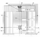
도 1은 시험기의 측면도이다.
도 2는 시험기의 일부분의 확대도이다.
도 3은 시험기의 일부분의 사시도이다.
도 4는 도 3의 선 Ⅳ-Ⅳ을 따라 취한 시험기의 단면도이다.
도 5는 칼럼 브레이스가 없는 경우, 선택된 진동수에 있어서 시험기의 변형을 그림으로 도시한 것이다.
도 6은 칼럼 브레이스가 있는 경우, 선택된 진동수에 있어서 시험기의 변형을 그림으로 도시한 것이다.
도 7은 서로 다른 길이의 시편에 대한 박스 모드 공명 진동수를 도시한다.
도 8은 칼럼 브레이스를 보여주는 개략도이다.1 is a side view of the testing machine.
2 is an enlarged view of a part of the testing machine.
3 is a perspective view of a portion of the testing machine;
FIG. 4 is a cross-sectional view of the testing machine taken along line IV-IV of FIG. 3 .
Figure 5 is a pictorial representation of the deformation of the testing machine at the selected frequency in the absence of column braces.
Figure 6 is a pictorial representation of the deformation of the tester at selected frequencies in the presence of column braces.
7 shows the box mode resonance frequencies for specimens of different lengths.
8 is a schematic diagram showing a column brace.
시험편(도시 생략)에 힘 또는 운동을 가하는 시험기(10)의 개략도가 도 1에 도시되어 있다. 시험기는 베이스(12)를 구비하는 프레임(11), 베이스(12)로부터 상향 연장되는 한 쌍의 칼럼(14), 및 베이스(12)로부터 이격된 위치에서 두 칼럼(14)에 연결된 크로스헤드(16)를 포함한다. 적어도 한 쌍의 시편 홀더(20A, 20B)가 제공된다. 제1 시편 홀더(20A)는 크로스헤드(16)에 의해 지지되고 베이스(12)를 향해 연장된다. 제2 시편 홀더(20B)는 베이스(12)에 의해 지지되고 크로스헤드(16)를 향해 연장된다. 상기 베이스(12)는 시험기(10)에 있어서 크로스헤드(16)와 가장 가까운 각각의 칼럼(14)에 연결된 부분이라는 점에 주목해야 할 필요가 있다.A schematic diagram of a
이들 시편 홀더(20A, 20B) 중 하나와 대응하는 베이스(12) 또는 크로스헤드(16)의 사이에 액추에이터(22)가 직렬로 연결되어 있다. 도시된 실시형태에서, 제1 시편 홀더(20A)는 크로스헤드(16)에 의해 지지되는 힘 변환기(24)에 연결되어 있고, 제2 시편 홀더(20B)는 베이스(12)에 있는 액추에이터(22)에 결합되어 있다. 다른 실시형태에서, 액추에이터(22)는 크로스헤드(16)에 위치되는 반면, 힘 변환기(24)는 베이스(12)에 연결될 것이라는 점에 주목해야 할 필요가 있다.An
도 3과 도 4를 참조해 보면, 여기에 브레이스(30)로서 도시된 브레이스 어셈블리가 각각의 칼럼(14)에 연결되어 있고, 칼럼들(14) 사이에 걸쳐 있으며, 브레이스(30)는 각각의 칼럼(14)에 그 길이를 따라 베이스(12)와 크로스헤드(16) 사이에 있는 위치에서 연결되어 있다. 시험기(10)는 여러 진동의 공명 모드를 갖는다. 중요한 진동 모드 중 하나를 통상적으로 "박스 모드"라 한다. 예를 들어 베이스(12)와 크로스헤드(16) 사이에 있는 칼럼들(14)의 대략 중간-스팬 등에서, 칼럼들(14)을 함께 결합하는 브레이스(30)를 추가함으로써, 브레이스(30)가 없는 시험기에 비해, 박스 모드 진동수의 현저한 증가가 얻어진다. 도 5와 도 6은 브레이스(30)가 있는 경우와 브레이스(30)가 없는 경우 각각에 시험기(10)를 과장된 형태로 그림으로 도시하고 있다. 도 5에서, 브레이스(30)가 없는 시험기(10)는 칼럼들(14)의 대략 중간-스팬에서 현저한 변형이 일어나고, 이 변형은 줄어들면서 베이스(12)를 향해 아래쪽으로 그리고 크로스헤드(16)를 향해 위쪽으로 이어진다.3 and 4 , a brace assembly, shown herein as
도 6에서, 브레이스(30)는 칼럼들(14) 사이에서 연장된다. 상기 중간-스팬에서의 칼럼들(14)의 변형은 현저히 감소되지만, 추가적인 변형이 크로스헤드(16)에 존재할 수 있다. 박스 모드 공명 진동수는 브레이스(30)가 없는 경우의 약 715 ㎐로부터 브레이스(30)가 있는 경우의 약 824 ㎐로 증가된다는 것이 더 중요하다. 도 7은 서로 다른 길이의 시편에 대한 박스 모드 공명 진동수를 도시한다.6 , braces 30 extend between
도 3과 도 6에는 브레이스(30)가 대략 칼럼들(14)의 중간-스팬에 배치되어 있는 경우가 도시되어 있지만, 칼럼들(14)을 따라 있는 다른 위치도 유익을 제공할 수 있다. 일반적으로, 브레이스(30)는 각각의 칼럼(14)에, 서로 멀리 떨어져 있는 시편 홀더들(20A, 20B)의 단부들 사이에 있어서의 칼럼들의 길이를 따라 있는 위치에서 연결된다. 추가적인 실시형태에서, 브레이스(30)는 서로 가장 가까운 시편 홀더들(20A, 20B)의 단부들 사이에서 각각의 칼럼(14)에 연결된다. 추가적인 실시형태에서, 브레이스(30)는 서로 가장 가까운 시편 홀더들(20A, 20B)의 단부들 사이 거리의 약 25% 내지 약 75% 범위의 위치에서 각각의 칼럼(14)에 연결된다. 또 다른 실시형태에서, 브레이스(30)는 서로 가장 가까운 시편 홀더들(20A, 20B)의 단부들 사이 거리의 약 40% 내지 약 60% 범위의 위치에서 각각의 칼럼에 연결된다. 브레이스(30)는 또한, 서로 가장 가까운 시편 홀더들(20A, 20B)의 단부들 사이 거리의 약 50%에서 각각의 칼럼(14)에 연결될 수 있다.Although FIGS. 3 and 6 show the case where the
각 칼럼(14)은 축(32)을 포함하고, 브레이스(30)는 두 칼럼(14)의 축(32)을 갖는 평면(43)에 평행한 칼럼들(14) 사이의 평면들(41)을 따라 연장되는 부분(40)을 포함한다. 일 실시형태에서, 브레이스(30)의 각 단부에 있어서의 부분들(40)은 각 칼럼(14)에 대한 이등분 평면(45)에 있어서의 각 칼럼(14)의 외부 표면의 대향하는 변들에 연결되어 있고, 이등분 평면들(45)은 칼럼들(14) 사이에서 연장되는 평면(43)에 수직이다. 이등분 평면들(45)과 만나는 칼럼들(14)의 외부 표면 상의 지점들에서 브레이스(30)를 배치 또는 연결함으로써 칼럼들(14)에 최대의 강성이 제공되는 것으로 고려된다. 통상적으로, 칼럼들(14)의 축에 수직인 평면에서 연장되는 부분들(40)과 같은 구조 요소를 제공하도록, 브레이스(30)는 칼럼들(14)에 장착된다.Each
도 4를 참조해 보면, 브레이스(30)는 개구(42)로서, 시편 홀더들(20A, 20B) 사이의 축(44)(도 2)이 통과해 연장되는 개구를 포함할 수 있다. 따라서, 개구(42)는 시험편이 브레이스(30)의 부분들과 접촉하지 않고서 축(44)을 따라 시편 홀더들(20A, 20B)에 연결되는 것을 허용한다. 개구(42)는, 로딩 중에 시험편의 단부가 개구(42)를 통해 연장되는 것을 허용하는 크기일 수 있고, 이 경우 시험편의 양단부는 이후에 서로 다른 시편 홀더들(20A, 20B)에 부착될 수 있다. 예시적인 실시형태에서, 칼럼들(14)은 시험 대상 시험편들보다 넓을 수 있는 상대적으로 큰 직경을 갖지만; 도시된 브레이스(30)의 구성은, 브레이스(30)가 대략 칼럼들(14)의 직경보다 크거나 같은 크기인 개구를 가질 수 있는 것에 제한되어서는 안 되고, 이러한 경우 브레이스(30)에 있어서 칼럼들(14) 사이에서 연장되는 부분들이 필요에 따라 보다 큰 개구를 제공하도록 이중 화살표(47)로 나타내어진 방향 중 어느 한 방향 또는 양방향에서 바깥쪽으로 휘어질 수 있는 점에 주목해야 할 필요가 있다.Referring to FIG. 4 , the
다른 실시형태에서는, 브레이스(30)에 있어서 개구(42)의 둘레의 일부를 획정하는 부분(46)이, 시험편이 개구(42)에 삽입되거나 개구로부터 제거되는 것을 허용하도록 제거 가능하다. 이후에, 시험편이 시편 홀더(20A, 20B)에 장착되면, 상기 부분(46)은 재부착된다. 상기 제거 가능한 부분(46)은 나사 볼트 등과 같은 적절한 패스너(48)를 사용하여 브레이스(30)의 다른 부분에 연결될 수 있다. 다른 실시형태에서는, 상기 부분(46)을 브레이스(30)의 다른 부분에 고정하는 데 단 하나의 패스너만이 요구되도록, 상기 부분(46)은 일단부에서 힌지 연결될 수 있다.In another embodiment, the
브레이스의 단부들(30A, 30B)은 예를 들어 칼럼들의 외부 표면에서 칼럼들(14)에 고정된다. 일 실시형태에서, 각 단부(30A, 30B)는 칼럼들(14)의 외부 표면에 클램핑되는 클램프를 포함한다. 예를 들어, 각 단부(30A, 30B)에 있는 클램프는 나사 볼트 등과 같은 하나 이상의 적절한 패스너(51)를 갖는 분할 칼라를 포함할 수 있는데, 이 분할 칼라는 칼럼들(14)의 외부 표면에 클램핑되도록 브레이스(30)의 내경을 수축 또는 확대할 수 있다(또는 브레이스의 별개의 부분들을 함께 장착할 수도 있다).The ends 30A, 30B of the brace are fixed to the
본원에 개시된 브레이스(30)는 한 쌍의 칼럼을 갖는 시험기에만 제한되는 것이 아니라, 다른 다중-칼럼 시험기에 사용될 수 있다는 점에 주목해야 할 필요가 있다. 도 8은 4개의 칼럼(14)을 구비하는 시험기(10')의 개략적인 상측 단면도이다. 이러한 시험기에서는, [브레이스(30)와 유사한] 복수의 브레이스(52, 53, 54, 55)가 이웃하는 칼럼들(14) 사이에 사용되어, 개별 브레이스들(52-55)이 이웃하는 칼럼들 사이에 걸쳐 있는 구조(56)를 형성한다. 추가적으로 또는 대안적으로, 4개의 칼럼(14)이 정사각형 또는 직사각형으로 배치되어 있는 경우, 브레이스들(58, 59)은 이웃하지 않은 칼럼들(14) 사이에서, 예를 들어 대각선으로 연장될 수 있다. 이에 따라 대각선으로 연장되는 브레이스들(58, 59)은 잠재적으로, 시편 홀더들 사이에서 연장되는 시험편의 축을 연장하거나 이등분할 것이고; 따라서 브레이스들(58, 59)은 또한, 예를 들어 브레이스(30)의 개구(42)와 유사한 개구를 포함할 수 있다.It should be noted that the
다시 도 1을 참조하면, 시험기(10)는, 베이스(12)에 있어서 크로스헤드(16)로부터 멀리 떨어져 있는 측에 있는 칼럼들(14)의 단부들을 연결하는 연결 요소(70)에까지 베이스(12)를 통하여 연장되는 칼럼들(14)을 구비한다. 마찬가지로, 필요에 따라, 칼럼들(14)은 점선으로 나타내어진 바와 같이 크로스헤드(16)를 통과해 연장될 수 있고, 베이스(12)로부터 멀리 떨어져 있는 칼럼들의 단부들에서 구조 요소(72)로 연결될 수 있다. 도 1의 실시형태에서, 베이스(12)는 칼럼들(14)을 따라 이동 가능하고, 베이스(12)의 부분들을 칼럼들(14)의 외부 표면에 클램핑하는 공압 또는 유압 액추에이터를 포함하는 클램핑 디바이스(80)로 칼럼들에 선택적으로 고정된다. 시험받고 있는 시험편의 길이에 따라 시편 홀더들(20A, 20B) 사이의 거리를 변경하도록, 베이스(12)는 조정 가능하다.Referring again to FIG. 1 , the
도 3은 예를 들어 베이스(12)와 크로스헤드(16)의 사이에서 또는 대략 중간-스팬에서, 앞서 나타낸 바와 같은 위치들에 있는 제1 부분들에서 칼럼들(14)에 연결된 (개략적으로 도시된) 하나 이상의 거싯(81, 82, 83, 84)을 포함하는 다른 형태의 브레이스 어셈블리(8)를 도시한다. 거싯들(81-84)은 브레이스(30)에서 볼 수 있는 분할 칼라를 사용하여 칼럼들(14)에 장착될 수 있다. 거싯들(81-84)은 또한 도시된 바와 같이 베이스(12)에 견고히 고정되어 있지만, 필요에 따라 크로스헤드(16)에 고정될 수 있다.3 shows (schematically shown) connected to the
본 발명의 대상이 특정 환경, 구조적 특징 및/또는 방법론적 행위에 대한 언어로 기술되었지만, 법원에서 간주되어 오고 있는 바와 같이, 첨부된 청구범위에서 한정되는 본 발명의 대상은 전술한 환경, 특정 피처 또는 행위에 제한되지 않는 것으로 이해되어야 한다. 오히려, 전술한 환경, 특정 피처 및 행위는 청구범위를 구현하는 예시적인 형태로 개시된다.Although the subject matter of the present invention has been described in language of specific circumstances, structural features and/or methodological acts, as has been contemplated in courts, the subject matter of the present invention defined in the appended claims is subject to the foregoing circumstances, specific features, and so forth. or to be construed as not limited to the act. Rather, the foregoing circumstances, specific features, and acts are disclosed as example forms of implementing the claims.
Claims (21)
베이스;
상기 베이스에 연결된 적어도 한 쌍의 칼럼;
상기 베이스로부터 이격된 위치에서 상기 칼럼에 연결된 크로스헤드;
적어도 한 쌍의 시편 홀더로서, 제1 시편 홀더가 상기 크로스헤드에 의해 지지되어 있고 상기 베이스에 면하며, 제2 시편 홀더가 상기 베이스에 의해 지지되어 있고, 상기 베이스는 상기 크로스헤드와 가장 가까운 각각의 칼럼에 연결된 부분인 것인 적어도 한 쌍의 시편 홀더;
상기 시편 홀더 중 하나와 대응하는 베이스 또는 크로스헤드의 사이에 직렬로 연결된 액추에이터; 및
각각의 칼럼에 연결되어 있고, 칼럼들 사이에 걸쳐 있는 브레이스로서, 브레이스는 각각의 칼럼에 그 길이를 따라 상기 베이스와 상기 크로스헤드 사이에 있는 위치에서 연결되어 있는 것인 브레이스
를 포함하는 시험기.As a tester:
Base;
at least one pair of columns connected to the base;
a crosshead coupled to the column at a location spaced from the base;
at least a pair of specimen holders, wherein a first specimen holder is supported by the crosshead and faces the base, and a second specimen holder is supported by the base, the bases each closest to the crosshead At least one pair of specimen holders that are part of the column connected to;
an actuator connected in series between one of the specimen holders and a corresponding base or crosshead; and
a brace connected to each column and spanning between the columns, wherein the brace is connected to each column along its length at a location between the base and the crosshead.
A testing machine comprising a.
베이스;
상기 베이스에 연결된 적어도 한 쌍의 칼럼;
상기 베이스로부터 이격된 위치에서 상기 칼럼에 연결된 크로스헤드;
적어도 한 쌍의 시편 홀더로서, 제1 시편 홀더가 상기 크로스헤드에 의해 지지되어 있고 상기 베이스에 면하며, 제2 시편 홀더가 상기 베이스에 의해 지지되어 있고, 상기 베이스는 상기 크로스헤드와 가장 가까운 각각의 칼럼에 연결된 부분인 것인 적어도 한 쌍의 시편 홀더;
상기 시편 홀더 중 하나와 대응하는 베이스 또는 크로스헤드의 사이에 직렬로 연결된 액추에이터; 및
각각의 칼럼의 길이를 따라 상기 베이스와 상기 크로스헤드 사이에 있는 위치에서 각각의 칼럼에 연결되어 있는 브레이스 어셈블리로서, 상기 칼럼들을 함께 연결하거나 상기 칼럼들을 상기 베이스 또는 상기 크로스헤드에 연결하도록 상기 칼럼들 사이에 걸쳐 있는 것인 브레이스 어셈블리
를 포함하는 시험기.As a tester:
Base;
at least one pair of columns connected to the base;
a crosshead coupled to the column at a location spaced from the base;
at least a pair of specimen holders, wherein a first specimen holder is supported by the crosshead and faces the base, and a second specimen holder is supported by the base, the bases each closest to the crosshead At least one pair of specimen holders that are connected to the column of the;
an actuator connected in series between one of the specimen holders and a corresponding base or crosshead; and
a brace assembly coupled to each column at a location between the base and the crosshead along the length of each column, wherein the columns are configured to connect the columns together or connect the columns to the base or the crosshead a brace assembly that spans between
A testing machine comprising a.
Applications Claiming Priority (3)
| Application Number | Priority Date | Filing Date | Title |
|---|---|---|---|
| US202062961178P | 2020-01-14 | 2020-01-14 | |
| US62/961,178 | 2020-01-14 | ||
| PCT/US2021/013248 WO2021146290A1 (en) | 2020-01-14 | 2021-01-13 | Testing system with column brace |
Publications (1)
| Publication Number | Publication Date |
|---|---|
| KR20220123413A true KR20220123413A (en) | 2022-09-06 |
Family
ID=74562050
Family Applications (1)
| Application Number | Title | Priority Date | Filing Date |
|---|---|---|---|
| KR1020227024355A KR20220123413A (en) | 2020-01-14 | 2021-01-13 | Test system with column braces |
Country Status (6)
| Country | Link |
|---|---|
| US (1) | US11852613B2 (en) |
| EP (1) | EP4090936A1 (en) |
| JP (1) | JP2023511284A (en) |
| KR (1) | KR20220123413A (en) |
| CN (1) | CN115038954A (en) |
| WO (1) | WO2021146290A1 (en) |
Family Cites Families (27)
| Publication number | Priority date | Publication date | Assignee | Title |
|---|---|---|---|---|
| US3102421A (en) | 1960-06-21 | 1963-09-03 | Union Carbide Corp | High speed tensile testing |
| US3158048A (en) | 1960-10-25 | 1964-11-24 | Warner Swasey Co | Impact machine |
| US3142980A (en) | 1962-07-02 | 1964-08-04 | Axel G H Andersen | Fast acting tensile tester |
| US3297284A (en) | 1964-11-06 | 1967-01-10 | Pellerin Corp Milnor | Suspension system for machines |
| US3442120A (en) | 1966-04-19 | 1969-05-06 | Mts System Corp | Servo valve controlled hydraulic resonant machine |
| DE1812328A1 (en) | 1968-12-03 | 1970-07-02 | Kieserling & Albrecht | Screw press |
| US3597960A (en) | 1969-02-14 | 1971-08-10 | Trw Inc | High intensity mechanical shock testing machine |
| GB1442048A (en) | 1974-03-26 | 1976-07-07 | Instron Ltd | Testing machines |
| CH644450A5 (en) | 1980-02-11 | 1984-07-31 | Russenberger Pruefmasch | DEVICE FOR THE VIBRATION STRENGTH TEST. |
| JPS5748632A (en) | 1980-08-06 | 1982-03-20 | Saginomiya Seisakusho Inc | Dynamic characteristic measuring device |
| US4478086A (en) | 1983-01-07 | 1984-10-23 | Mts Systems Corporation | Load frame crosshead construction |
| GB8723254D0 (en) * | 1987-10-03 | 1987-11-04 | Lifting Gear Hire Ltd | Load testing apparatus |
| FR2697912A1 (en) * | 1992-11-06 | 1994-05-13 | Nantes Ecole Centrale | Sample testing machine buffer interposed between jaw and operating rod - eliminates shock waves at metal impact or jaws, consists of two equal thickness rings of viscous and elastic materials e.g. polyurethane and teflon so increasing measurement accuracy |
| US5412995A (en) * | 1994-06-10 | 1995-05-09 | Factory Mutual Research Corporation | Single-ply roof cover fatigue tester |
| US5677494A (en) | 1996-03-05 | 1997-10-14 | Mcdonnell Douglas Corporation | Method for high strain-rate testing of specimens |
| AU6330898A (en) | 1997-02-21 | 1998-09-09 | Southwest Research Institute | High-cycle fatigue test machine |
| US5948994A (en) * | 1998-04-02 | 1999-09-07 | Jen; Ming-Hwa R. | Multi-functional test machine |
| TW365944U (en) | 1998-10-14 | 1999-08-01 | Gigga Corp | Improved structure for shock absorber of bicycle |
| US6601456B1 (en) | 2001-06-06 | 2003-08-05 | Southwest Research Institute | Fretting fixture for high-cycle fatigue test machines |
| JP3836437B2 (en) | 2003-01-16 | 2006-10-25 | 株式会社鷺宮製作所 | Load test machine |
| WO2005026685A2 (en) | 2003-09-05 | 2005-03-24 | Nhk International Corp. | Method and apparatus for fatigue testing |
| US7404334B2 (en) | 2006-06-29 | 2008-07-29 | Mts Systems Corporation | Testing system with soft reaction structure |
| US7568397B2 (en) * | 2007-03-02 | 2009-08-04 | Bridgestone Firestone North American Tire, Llc | Magnetic stability for test fixture |
| CN202710413U (en) * | 2012-07-11 | 2013-01-30 | 南车株洲电力机车有限公司 | Welded joint destructive test pressing mould |
| WO2019045646A1 (en) * | 2017-08-31 | 2019-03-07 | Forefront Additive Manufacturing Pte Ltd | Method and apparatus for mechanical testing of an orthosis |
| CN109839306B (en) * | 2019-01-26 | 2021-06-15 | 长沙理工大学 | Loading device for testing of span-cable stayed bridge and assembling method thereof |
| JP2023016281A (en) * | 2021-07-21 | 2023-02-02 | 株式会社島津製作所 | Material tester |
-
2021
- 2021-01-13 KR KR1020227024355A patent/KR20220123413A/en unknown
- 2021-01-13 EP EP21704108.6A patent/EP4090936A1/en active Pending
- 2021-01-13 CN CN202180007625.9A patent/CN115038954A/en active Pending
- 2021-01-13 JP JP2022542972A patent/JP2023511284A/en active Pending
- 2021-01-13 WO PCT/US2021/013248 patent/WO2021146290A1/en unknown
- 2021-01-13 US US17/148,267 patent/US11852613B2/en active Active
Also Published As
| Publication number | Publication date |
|---|---|
| US11852613B2 (en) | 2023-12-26 |
| CN115038954A (en) | 2022-09-09 |
| EP4090936A1 (en) | 2022-11-23 |
| JP2023511284A (en) | 2023-03-17 |
| US20210215587A1 (en) | 2021-07-15 |
| WO2021146290A1 (en) | 2021-07-22 |
Similar Documents
| Publication | Publication Date | Title |
|---|---|---|
| US4058007A (en) | Vibrating wire measuring instrument | |
| Boltezar et al. | Identification of transverse crack location in flexural vibrations of free–free beams | |
| EP2041544B1 (en) | Testing system with soft reaction structure | |
| JP2004219304A (en) | Load testing machine | |
| US5245876A (en) | Dual beam complex modulus apparatus | |
| KR20220123413A (en) | Test system with column braces | |
| CN106950020A (en) | The test device of insulator vibrating fatigue performance | |
| DE10210541A1 (en) | Measurement of mechanical strains on elastically deformable surfaces, e.g. membranes, using vibration sensitive elements that are set vibrating so that the resultant output signal can be measured and evaluated to determine strain | |
| JP2013167557A (en) | Vibration testing machine | |
| JP3970204B2 (en) | Load test method | |
| SU1379695A1 (en) | Apparatus for testing tubular specimens for fatigue | |
| SU1525548A1 (en) | Installation for deformation of specimens of materials | |
| SU1516817A1 (en) | Method of vibratory check of single-dimensional structures | |
| CN220207403U (en) | Concrete bonding degree detection device | |
| RU2089874C1 (en) | Method of diagnostics of injuries of structures under cyclic loads | |
| SU1276468A1 (en) | Method of testing spot welds for static vibration strength | |
| JPH0210245A (en) | Apparatus for measuring breakdown strength of material | |
| CN205940918U (en) | Shaking table fixture device | |
| JPS60196643A (en) | Strength measuring method of brittle material | |
| RU2308699C1 (en) | Method to determine maximal deflection of single composite timber beams with enlarging joints | |
| RU2175759C2 (en) | Method of determination of optimal location of strengthening support in rod in case of loss of stability | |
| SU1548679A2 (en) | Method of investigating aerodynamic connection of flat grid blade vibrations in aerodynamic flow | |
| Hurlebaus | Nondestructive evaluation of composite laminates | |
| RU2170426C2 (en) | Method of vibroacoustic monitoring of single-axle structures | |
| JPS645230Y2 (en) |