KR20220108032A - fuse - Google Patents
fuse Download PDFInfo
- Publication number
- KR20220108032A KR20220108032A KR1020227012692A KR20227012692A KR20220108032A KR 20220108032 A KR20220108032 A KR 20220108032A KR 1020227012692 A KR1020227012692 A KR 1020227012692A KR 20227012692 A KR20227012692 A KR 20227012692A KR 20220108032 A KR20220108032 A KR 20220108032A
- Authority
- KR
- South Korea
- Prior art keywords
- casing
- fuse
- fixing member
- frame
- terminal
- Prior art date
Links
Images


Classifications
-
- H—ELECTRICITY
- H01—ELECTRIC ELEMENTS
- H01H—ELECTRIC SWITCHES; RELAYS; SELECTORS; EMERGENCY PROTECTIVE DEVICES
- H01H85/00—Protective devices in which the current flows through a part of fusible material and this current is interrupted by displacement of the fusible material when this current becomes excessive
- H01H85/02—Details
- H01H85/04—Fuses, i.e. expendable parts of the protective device, e.g. cartridges
- H01H85/05—Component parts thereof
- H01H85/055—Fusible members
- H01H85/12—Two or more separate fusible members in parallel
-
- H—ELECTRICITY
- H01—ELECTRIC ELEMENTS
- H01H—ELECTRIC SWITCHES; RELAYS; SELECTORS; EMERGENCY PROTECTIVE DEVICES
- H01H85/00—Protective devices in which the current flows through a part of fusible material and this current is interrupted by displacement of the fusible material when this current becomes excessive
- H01H85/02—Details
- H01H85/04—Fuses, i.e. expendable parts of the protective device, e.g. cartridges
- H01H85/05—Component parts thereof
- H01H85/165—Casings
- H01H85/175—Casings characterised by the casing shape or form
-
- H—ELECTRICITY
- H01—ELECTRIC ELEMENTS
- H01H—ELECTRIC SWITCHES; RELAYS; SELECTORS; EMERGENCY PROTECTIVE DEVICES
- H01H85/00—Protective devices in which the current flows through a part of fusible material and this current is interrupted by displacement of the fusible material when this current becomes excessive
- H01H85/0078—Security-related arrangements
- H01H85/0082—Security-related arrangements preventing explosion of the cartridge
-
- H—ELECTRICITY
- H01—ELECTRIC ELEMENTS
- H01H—ELECTRIC SWITCHES; RELAYS; SELECTORS; EMERGENCY PROTECTIVE DEVICES
- H01H85/00—Protective devices in which the current flows through a part of fusible material and this current is interrupted by displacement of the fusible material when this current becomes excessive
- H01H85/02—Details
- H01H85/04—Fuses, i.e. expendable parts of the protective device, e.g. cartridges
- H01H85/05—Component parts thereof
- H01H85/143—Electrical contacts; Fastening fusible members to such contacts
-
- H—ELECTRICITY
- H01—ELECTRIC ELEMENTS
- H01H—ELECTRIC SWITCHES; RELAYS; SELECTORS; EMERGENCY PROTECTIVE DEVICES
- H01H85/00—Protective devices in which the current flows through a part of fusible material and this current is interrupted by displacement of the fusible material when this current becomes excessive
- H01H85/02—Details
- H01H85/20—Bases for supporting the fuse; Separate parts thereof
- H01H85/203—Bases for supporting the fuse; Separate parts thereof for fuses with blade type terminals
-
- H—ELECTRICITY
- H01—ELECTRIC ELEMENTS
- H01H—ELECTRIC SWITCHES; RELAYS; SELECTORS; EMERGENCY PROTECTIVE DEVICES
- H01H2231/00—Applications
- H01H2231/026—Car
-
- H—ELECTRICITY
- H01—ELECTRIC ELEMENTS
- H01H—ELECTRIC SWITCHES; RELAYS; SELECTORS; EMERGENCY PROTECTIVE DEVICES
- H01H69/00—Apparatus or processes for the manufacture of emergency protective devices
- H01H69/02—Manufacture of fuses
-
- H—ELECTRICITY
- H01—ELECTRIC ELEMENTS
- H01H—ELECTRIC SWITCHES; RELAYS; SELECTORS; EMERGENCY PROTECTIVE DEVICES
- H01H85/00—Protective devices in which the current flows through a part of fusible material and this current is interrupted by displacement of the fusible material when this current becomes excessive
- H01H85/02—Details
- H01H85/04—Fuses, i.e. expendable parts of the protective device, e.g. cartridges
- H01H85/05—Component parts thereof
- H01H85/143—Electrical contacts; Fastening fusible members to such contacts
- H01H85/153—Knife-blade-end contacts
-
- H—ELECTRICITY
- H01—ELECTRIC ELEMENTS
- H01H—ELECTRIC SWITCHES; RELAYS; SELECTORS; EMERGENCY PROTECTIVE DEVICES
- H01H85/00—Protective devices in which the current flows through a part of fusible material and this current is interrupted by displacement of the fusible material when this current becomes excessive
- H01H85/02—Details
- H01H85/04—Fuses, i.e. expendable parts of the protective device, e.g. cartridges
- H01H85/05—Component parts thereof
- H01H85/165—Casings
- H01H85/175—Casings characterised by the casing shape or form
- H01H85/1755—Casings characterised by the casing shape or form composite casing
-
- Y—GENERAL TAGGING OF NEW TECHNOLOGICAL DEVELOPMENTS; GENERAL TAGGING OF CROSS-SECTIONAL TECHNOLOGIES SPANNING OVER SEVERAL SECTIONS OF THE IPC; TECHNICAL SUBJECTS COVERED BY FORMER USPC CROSS-REFERENCE ART COLLECTIONS [XRACs] AND DIGESTS
- Y02—TECHNOLOGIES OR APPLICATIONS FOR MITIGATION OR ADAPTATION AGAINST CLIMATE CHANGE
- Y02E—REDUCTION OF GREENHOUSE GAS [GHG] EMISSIONS, RELATED TO ENERGY GENERATION, TRANSMISSION OR DISTRIBUTION
- Y02E60/00—Enabling technologies; Technologies with a potential or indirect contribution to GHG emissions mitigation
- Y02E60/10—Energy storage using batteries
Abstract
본원 발명은 나란히 배치된 복수의 용단부를 구비하고 있어도, 케이싱 내부를 공간 절약화 할 수 있는 퓨즈를 제공한다. 한 쌍의 단자부(11) 사이에 설치된 용단부(120)를 가지는 퓨즈 엘리먼트(100)와, 단자부(110)를 외측으로 돌출시키면서, 퓨즈 엘리먼트(100)의 일부를 수용하는 케이싱(290)을 구비한 퓨즈(400)로서, 단자부(110)에는, 2개 이상의 용단부(120)가 단자부(110)끼리를 연결한 단자부 방향(Y)에 직교하는 횡방향(X)으로 나란히 놓여져 연결되어 있고, 케이싱(290)은 퓨즈 엘리먼트(100)를 끼워 넣도록 수용하는 2개의 케이싱 분할편(200)을 구비하고, 각 케이싱 분할편(200)은 상기 각 케이싱 분할편(200)의 주위를 일주하는 틀 형상 고정부재(300)에 의하여 서로 고정되어 있고, 케이싱(200)의 수용 공간(N1)은 상하 방향(Z)의 최대폭(L1)이 횡방향(X)의 최대폭(L2)보다 좁게 되어 있는 것을 특징으로 한다. The present invention provides a fuse capable of saving space inside a casing even if it has a plurality of fusing parts arranged side by side. A fuse element 100 having a fusing part 120 installed between a pair of terminal parts 11 and a casing 290 accommodating a part of the fuse element 100 while protruding the terminal part 110 to the outside; As one fuse 400, in the terminal part 110, two or more fusing parts 120 are placed side by side in a lateral direction (X) orthogonal to the terminal part direction (Y) connecting the terminal parts 110 to each other and are connected, The casing 290 includes two casing split pieces 200 for accommodating the fuse element 100 to be inserted therein, and each casing split piece 200 is a frame circumscribing the respective casing split pieces 200 . It is fixed to each other by the shape fixing member 300, and the accommodation space (N1) of the casing 200 has a maximum width (L1) in the vertical direction (Z) is narrower than the maximum width (L2) in the horizontal direction (X) characterized.
Description
본원 발명은, 주로 자동차용 전기 회로 등에 이용되는 퓨즈에 관한 것이며, 특히, 케이싱 내에 퓨즈 엘리먼트를 수용하는 퓨즈에 관한 것이다.BACKGROUND OF THE INVENTION Field of the Invention The present invention relates mainly to a fuse used in an electric circuit for automobiles and the like, and more particularly, to a fuse housing a fuse element in a casing.
종래부터, 퓨즈는 자동차 등에 탑재되어 있는 전기 회로나, 전기 회로에 접속되어 있는 각종 전장품을 보호하기 위하여 이용되어 왔다. 자세한 것은, 전기 회로 중에 의도하지 않은 과전류가 흘렀을 경우에, 퓨즈에 내장된 퓨즈 엘리먼트의 용단부(溶斷部)가 과전류에 의한 발열에 의해 용단되어, 각종 전장품에 과도한 전류가 흐르지 않도록 보호하고 있다.DESCRIPTION OF RELATED ART Conventionally, a fuse has been used in order to protect the electric circuit mounted in a motor vehicle etc., and various electric devices connected to an electric circuit. Specifically, when an unintentional overcurrent flows in an electric circuit, the fusing part of the fuse element built into the fuse is fused by heat generated by the overcurrent, thereby protecting various electronic components from flowing excessive current. .
그리고, 이 퓨즈는 용도에 따라 여러가지 종류가 있고, 예를 들면, 비교적 큰 과전류로부터 보호하기 위한 특허문헌 1에 기재된 퓨즈가 알려져 있다.And this fuse has various types according to a use, For example, the fuse of patent document 1 for protecting from a comparatively large overcurrent is known.
이 특허문헌 1에 기재된 퓨즈는, 통 형상의 케이싱 내부에 퓨즈 엘리먼트를 수용하는 타입의 것이며, 한 쌍의 단자부와, 상기 단자부의 사이에 설치된 용단부를 가지는 퓨즈 엘리먼트를 구비한다. 또, 퓨즈의 용량을 늘리는 경우는, 복수의 용단부를 병렬로 하여 단자부간에 접속하고, 그 병렬로 나란히 놓여진 복수의 용단부를 수용할 수 있도록, 케이싱을 크게 할 필요가 있다. 이 케이싱은 통 형상을 하고 있으므로, 복수의 용단부를 수용하기 위해서는, 직경을 크게 해야 한다. 단지, 케이싱의 내부에는, 용단부로부터 발생한 아크를 소호(消弧)하기 위한 소호재를 봉입하는 스페이스가 필요하기는 하지만, 직경을 크게 한 케이싱에 있어서는, 그 소호재를 봉입하는데 필요한 스페이스 이상의 불필요한 스페이스가 존재하여, 낭비가 생기고 있었다.The fuse described in Patent Document 1 is of a type that accommodates a fuse element inside a cylindrical casing, and includes a pair of terminal portions and a fuse element having a fusing portion provided between the terminal portions. Moreover, when increasing the capacity of the fuse, it is necessary to enlarge the casing so that a plurality of fused portions are connected in parallel to each other, and the plurality of fused portions arranged in parallel can be accommodated. Since this casing has a cylindrical shape, in order to accommodate a several fusion|melting edge part, the diameter must be enlarged. However, in the inside of the casing, a space for enclosing the arc extinguishing material for extinguishing the arc generated from the fusion end is necessary, but in a casing with a larger diameter, more than the space required to enclose the arc extinguishing material is unnecessary. Space existed, and wastage was occurring.
그래서, 본원 발명은 나란히 배치된 복수의 용단부를 구비하고 있어도, 케이싱 내부를 공간 절약화 할 수 있는 퓨즈를 제공한다.Then, this invention provides the fuse which can save the space inside a casing even if it is provided with the some fusion|melting part arrange|positioned side by side.
상기 과제를 해결하기 위하여, 본원 발명의 퓨즈는 한 쌍의 단자부 사이에 설치된 용단부를 가지는 퓨즈 엘리먼트와, 상기 단자부를 외측으로 돌출시키면서, 상기 퓨즈 엘리먼트의 일부를 수용하는 케이싱을 구비한 퓨즈로서, 상기 단자부에는, 2이상의 상기 용단부가 상기 단자부끼리를 연결한 단자부 방향으로 직교하는 횡방향으로 나란히 놓여져 연결되어 있고, 상기 케이싱은 상기 퓨즈 엘리먼트를 끼워 넣도록 수용하는 2개의 케이싱 분할편을 구비하고, 상기 각 케이싱 분할편은 상기 각 케이싱 분할편의 주위를 일주하는 틀 형상 고정 부재에 의하여, 서로 고정되어 있으며, 상기 케이싱의 수용 공간은 상기 상하 방향의 최대폭이 상기 횡방향의 최대폭보다 좁게 되어 있는 것을 특징으로 한다.In order to solve the above problems, a fuse of the present invention is a fuse including a fuse element having a fusing part installed between a pair of terminal parts, and a casing accommodating a part of the fuse element while projecting the terminal part to the outside, In the terminal part, two or more of the fused ends are arranged and connected in a transverse direction orthogonal to the direction of the terminal part connecting the terminal parts to each other, and the casing includes two casing division pieces for accommodating the fuse element to be inserted therein; Each casing split piece is fixed to each other by a frame-shaped fixing member circumferentially around the respective casing split piece, and the housing space of the casing is characterized in that the maximum width in the vertical direction is narrower than the maximum width in the lateral direction. do.
상기 특징에 의하면, 수용 공간의 상하 방향의 최대폭을, 횡방향의 최대폭보다 좁게 했기 때문에, 케이싱의 수용 공간의 상하 방향의 스페이스를 종래보다 작게 하여, 불필요한 스페이스를 생략할 수 있다. 또, 각 케이싱 분할편의 주위를 일주하는 틀 형상 고정 부재에 의하여, 케이싱 분할편을 서로 고정함으로써, 케이싱 분할편 내부로부터 외측으로 향하는 가스압에 강하게 견딜 수 있어 케이싱이 파손되는 것을 방지하고 있다.According to the above feature, since the maximum width in the vertical direction of the accommodating space is made narrower than the maximum width in the lateral direction, the space in the vertical direction of the housing space of the casing can be made smaller than before, and unnecessary space can be omitted. In addition, by fixing the casing fragments to each other by means of a frame-shaped fixing member circumferentially around each of the casing fragments, it is possible to strongly withstand the gas pressure from the inside of the casing fragments to the outside, thereby preventing the casing from being damaged.
또한, 본원 발명의 퓨즈는, 상기 틀 형상 고정 부재는 상기 단자부 방향에서 상기 단자부를 둘러싸도록, 상기 각 케이싱 분할편을 서로 고정하고 있는 것을 특징으로 한다.Further, in the fuse of the present invention, the frame-shaped fixing member is characterized in that the respective casing division pieces are fixed to each other so that the frame-shaped fixing member surrounds the terminal portion in the direction of the terminal portion.
상기 특징에 의하면, 퓨즈 엘리먼트의 단자부가 관통한 케이싱 부분에 있어서, 케이싱끼리의 고정력이 약해지는 것을 방지하여, 케이싱이 가스압에 의하여 파손되는 것을 방지하고 있다.According to the above feature, in the portion of the casing through which the terminal portion of the fuse element penetrates, the fixing force between the casings is prevented from weakening, and the casing is prevented from being damaged by the gas pressure.
또한, 본원 발명의 퓨즈는 상기 틀 형상 고정 부재는 상기 횡방향의 최대폭이, 상기 상하 방향의 최대폭보다 큰 것을 특징으로 한다.In the fuse of the present invention, the frame-shaped fixing member is characterized in that the maximum width in the lateral direction is greater than the maximum width in the vertical direction.
상기 특징에 의하면, 틀 형상 고정 부재가 횡방향으로 연장된 구조를 구비함으로써, 가스압이 강하게 걸리는 케이싱 부분(예를 들면, 바닥벽)에서, 횡방향을 따른 보다 넓은 범위를 둘러싸고 고정할 수 있어, 케이싱이 가스압에 의하여 파손되는 것을 보다 효과적으로 방지하고 있다.According to the above feature, since the frame-shaped fixing member has a structure extending in the transverse direction, it is possible to surround and fix a wider range along the transverse direction in the casing part (for example, the bottom wall) where the gas pressure is strongly applied, The casing is more effectively prevented from being damaged by gas pressure.
또한, 본원 발명의 퓨즈는 상기 틀 형상 고정 부재는 타원형 형상임과 동시에, 상기 틀 형상 고정 부재를 고정하는 각 케이싱 분할편 주위의 부분과 대응하는 형상을 하고 있는 것을 특징으로 한다.Further, the fuse of the present invention is characterized in that the frame-shaped fixing member has an elliptical shape and has a shape corresponding to a portion around each of the casing division pieces for fixing the frame-shaped fixing member.
상기 특징에 의하면, 케이싱 분할편 주위의 일부와 틀 형상 고정 부재와의 사이에 간극이 생기기 어렵기 때문에, 틀 형상 고정 부재에 의한 케이싱 분할편으로의 고정력이 국소적으로 약해지는 부분이 생기기 어렵다. 그 결과, 케이싱이 가스압에 의하여 파손되는 것을 보다 효과적으로 방지하고 있는 것이다.According to the above feature, since a gap is hardly formed between a part of the periphery of the casing divided piece and the frame-shaped fixing member, it is difficult to produce a portion where the fixing force to the casing divided piece by the frame-shaped fixing member is locally weakened. As a result, the casing is more effectively prevented from being damaged by the gas pressure.
또한, 본원 발명의 퓨즈는, 상기 단자부와 상기 용단부는 동일한 재료로 일체 성형되어 있는 것을 특징으로 한다.Further, the fuse of the present invention is characterized in that the terminal portion and the fused portion are integrally molded from the same material.
상기 특징에 의하면, 퓨즈 엘리먼트의 제조가 용이함과 함께, 용단부와 단자부의 전기적 접속이 확실하게 이루어진다.According to the above feature, the fuse element can be easily manufactured, and electrical connection between the fusing section and the terminal section is reliably achieved.
또한, 본원 발명의 퓨즈는, 상기 용단부는 상기 퓨즈 엘리먼트의 다른 부분보다 판 두께가 얇은 것을 특징으로 한다.Further, in the fuse of the present invention, the fuse portion is characterized in that the plate thickness is thinner than other portions of the fuse element.
상기 특징에 의하면, 용단부를 형성하기 쉽고, 또, 그 주변 부재를 가공하기 쉽다.According to the said characteristic, it is easy to form a fused-end part, and it is easy to process the peripheral member.
상기와 같이, 본원 발명의 퓨즈에 의하면, 나란히 배치된 복수의 용단부를 구비하고 있어도, 케이싱 내부를 공간 절약화 할 수 있다.As mentioned above, according to the fuse of this invention, even if it is provided with the some fusion|melting part arrange|positioned side by side, the space inside a casing can be saved.
도 1(a)는 본원 발명의 실시 형태 1에 따른 퓨즈의 퓨즈 엘리먼트를 전개한 상태의 평면도, 도1(b)는 퓨즈 엘리먼트를 굴곡 성형한 상태의 평면도이다.
도 2(a)는 굴곡 성형된 퓨즈 엘리먼트의 전체 사시도, 도 2(b)는 굴곡 성형된 퓨즈 엘리먼트의 측면도이다.
도 3(a)는 케이싱 분할편의 전체 사시도, 도 3(b)는 케이싱 분할편의 측면도, (c)는 케이싱 분할편의 A-A단면도이다.
도 4(a)는 퓨즈를 구성하는 각 부재를 분해하여 나타낸 전체 사시도, 도 4(b)는 틀 형상 고정 부재를 부착하는 모습을 나타낸 전체 사시도이다.
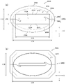
도 5(a)는 완성된 퓨즈의 전체 사시도, 도 5(b)는 퓨즈의 측면도이다.
도 6은 도 5(a)의 B-B단면도이다.
도 7(a)는 본원 발명의 실시 형태 2에 따른 퓨즈의 측면도, 도 7(b)는 본원 발명의 실시 형태 3에 따른 퓨즈의 측면도이다.Fig. 1 (a) is a plan view of a fuse element of a fuse according to Embodiment 1 of the present invention in an expanded state, and Fig. 1 (b) is a plan view of a state in which the fuse element is bent and molded.
Fig. 2(a) is an overall perspective view of the bend-molded fuse element, and Fig. 2(b) is a side view of the bend-formed fuse element.
Fig. 3(a) is an overall perspective view of the casing divided piece, Fig. 3(b) is a side view of the casing divided piece, and (c) is a sectional view AA of the casing divided piece.
Fig. 4(a) is an overall perspective view showing each member constituting the fuse disassembled, and Fig. 4(b) is an overall perspective view showing a state in which a frame-shaped fixing member is attached.
Fig. 5 (a) is an overall perspective view of the completed fuse, and Fig. 5 (b) is a side view of the fuse.
6 is a cross-sectional view taken along line BB of FIG. 5(a).
Fig. 7(a) is a side view of a fuse according to Embodiment 2 of the present invention, and Fig. 7(b) is a side view of a fuse according to Embodiment 3 of the present invention.
이하에, 본원 발명의 각 실시 형태에 대하여, 도면을 이용하여 설명한다. 또한 이하에서 설명하는 실시 형태에 있어서의 퓨즈의 각 부재의 형상이나 재질 등은, 일례를 나타내는 것으로서, 이들로 한정되는 것은 아니다. 또한 본 명세서에 기재되어 있는 「단자부 방향」이란, 퓨즈 엘리먼트의 양단의 단자부끼리를 연결한 축에 평행한 방향인 것이다. 또,「상하 방향」이란, 퓨즈 엘리먼트의 단자부 방향에 대하여 직각 방향인 것이다.EMBODIMENT OF THE INVENTION Below, each embodiment of this invention is demonstrated using drawings. In addition, the shape, material, etc. of each member of the fuse in embodiment demonstrated below show an example, and are not limited to these. In addition, the "terminal part direction" described in this specification is a direction parallel to the axis which connected the terminal parts of both ends of a fuse element. In addition, the "up-down direction" is a direction perpendicular to the direction of the terminal portion of the fuse element.
(실시 형태 1)(Embodiment 1)
도 1에서는, 본원 발명의 실시 형태 1에 따른 퓨즈의 퓨즈 엘리먼트(100)의 제조 공정에 대하여 설명한다. 또한 도 1(a)는 퓨즈 엘리먼트(100)를 전개한 상태의 평면도, 도 1(b)는 퓨즈 엘리먼트(100)를 굴곡 성형한 상태의 평면도, 도 2(a)는 굴곡 성형된 퓨즈 엘리먼트(100)의 전체 사시도, 도 2(b)는 굴곡 성형된 퓨즈 엘리먼트(100)의 측면도이다.In FIG. 1, the manufacturing process of the
우선, 구리나 그 합금 등의 도전성 금속으로 이루어지는, 평탄한 판재를, 도 1(a)에 나타낸 바와 같은 형상으로 프레스기 등으로 타발(punching)한다. 이 도 1(a)에 나타내는 바와 같은 소정의 형상으로 본떠진 한 장의 금속판에는, 양단의 단자부(110)와, 단자부(110) 사이의 평탄한 중간부(130)와, 중간부(130)에 용단부(120)가 복수 형성되어 있다. 구체적으로 설명하면, 용단부(120)는 중간부(130)에 작은 구멍을 형성하여 국소적으로 폭이 좁아진 선 형상의 복수의 용단 개소(120a)로 구성되어 있고, 각 용단 개소(120a)가, 전기 회로 등에 의도하지 않은 과전류가 흘렀을 때에, 발열하여 용단되어 과전류를 차단하는 것이다. 또한, 용단부(120)는, 폭이 좁아진 선 형상의 용단 개소(120a)로 구성되는 것으로 한정되지 않고, 전기 회로 등에 의도하지 않은 과전류가 흘렀을 때에, 발열하여 용단되어 과전류를 차단할 수 있다면, 중간부(130)에 용단되기 쉬운 금속재료를 국소적으로 배치하는 등의 임의의 구성을 채용할 수 있다.First, a flat plate material made of a conductive metal such as copper or an alloy thereof is punched out in a shape as shown in Fig. 1(a) with a press machine or the like. In a single metal plate modeled in a predetermined shape as shown in Fig. 1(a), the
다음으로, 도 1(a) 및 도 1(b)에 나타내는 바와 같이, 중간부(130)와 단자부(110)의 연결 개소 부근을, 절곡선(L1)에서 상방으로 접어 구부린다. 그러면, 중간부(130)는 단자부(110)보다 상방으로 조금 부풀어 오른 것 같이 연결된 상태가 된다. 이 절곡선(L1)은 단자부 방향(Y)과 직교하는 방향에 평행하게 되어 있다. 또한, 퓨즈 엘리먼트(100)의 단자부 방향(Y)에 평행한 절곡선(K1)에서, 가로로 늘어선 단자부(110)가 상하로 중첩되도록 접어 구부린다. 또한 퓨즈 엘리먼트(100)의 단자부 방향(Y)이란, 양측의 단자부(110)를 연결한 축에 평행한 방향인 것이다. 따라서, 절곡선(K1)도 양측의 단자부(110)를 연결한 축에 평행하게 된다.Next, as shown in FIG.1(a) and FIG.1(b), the vicinity of the connection point of the
그러면, 도 1(b), 및 도 2에 나타내는 입체적으로 접어 구부러진 퓨즈 엘리먼트(100)가 완성된다. 이 퓨즈 엘리먼트(100)는 단자부(110)에 2개의 중간부(130)가 횡방향(X)으로 나란히 놓여져 연결된 상태로 되어 있다. 즉, 단자부(110)에, 2개의 용단부(120)가 횡방향(X)으로 나란히 놓여져 연결되어 있으므로, 퓨즈 전체에서 용단부의 용량이 증가하고 있는 것이다. 그리고, 중간부(130)의 용단부(120)를 횡방향(X)으로 나란히 놓음으로써, 도 2(b)에 나타내는 바와 같이, 퓨즈 엘리먼트(100)의 단자부(110) 측은, 상하 방향(Z)의 높이(H1)보다, 횡방향(X)의 폭(H2)이 크게 되어 있다. 또한 횡방향(X)이란, 단자부 방향(Y)에 직교하는 방향이다. 또, 단자부(110)는 횡방향(X)과 단자부 방향(Y)에서 규정되는 면, 즉, X-Y평면을 따라 연장되어 있다. 또, 상하 방향(Z)이란, 횡방향(X) 및 단자부 방향(Y)의 각각에 직교하는 방향이다.Then, the three-dimensionally
또, 도 2에 나타내는 바와 같이, 상하 방향(Z)에 있어서 상대하는 중간부(130)는 단자부(110)를 사이에 두고 외측으로 부풀어 오르도록 구성되어 있다. 이 중간부(130)는 서로 이간하는 방향으로 절곡선(L1)에서 구부러져 있으므로, 상하 중간부(130)의 용단부(120)는 서로의 열적 영향을 받기 어려워, 소망의 용단 특성을 발휘할 수 있다. 또한 도 1 및 도 2에 나타내는 퓨즈 엘리먼트(100)에서는, 단자부(110)에는, 2개의 중간부(130)가 횡방향(X)으로 나란히 놓여져 연결되어 있지만, 이것으로 한정되지 않고, 단자부(110)에는 3개 이상의 중간부(130)가 횡방향(X)으로 나란히 놓여져 연결되어도 좋다. 또한 단자부(110)에, 3개 이상의 용단부(120)가 횡방향(X)으로 나란히 놓여진 경우는, 퓨즈 엘리먼트(100)는, 상하 방향(Z)의 높이(H1)보다, 횡방향(X)의 폭(H2)이 더 커진다.Moreover, as shown in FIG. 2, the intermediate|
또, 도 1 및 도 2에서는, 퓨즈 엘리먼트(100)의 용단부(120)와 단자부(110)는 동일한 재료로 일체 성형되어 있으므로, 퓨즈 엘리먼트(100)의 제조가 용이함과 함께, 용단부(120)와 단자부(110)의 전기적 접속이 확실하게 이루어진다. 또한 퓨즈 엘리먼트(100)의 용단부(120)와 단자부(110)는 동일한 재료로 일체 성형되어 있지만, 이것으로 한정되지 않고, 용단부(120)를 구비한 중간부(130)와 단자부(110)를 따로 따로 제조해 두고, 양자를 용접 등에 의해 연결해도 좋다. 또한, 퓨즈 엘리먼트(100)는, 구리나 그 합금 등의 도전성 금속으로 이루어지는 평탄한 판재를 도 1(a)에 나타내는 바와 같은 형상으로 프레스기 등으로 타발하여 형성하고 있지만, 이 판재는, 용단부(120)를 구비한 중간부(130)의 판 두께만이 얇고, 단자부(110)의 판 두께가 두꺼운 한 장의 판재, 즉, 두께가 균일하지 않고, 용단부(120)를 구성하는 부분의 판 두께만이, 다른 부분(단자부(110) 등)의 판 두께보다 얇은 한 장의 판재(이형재(異形材))로 되어 있다. 그 때문에, 판 두께가 얇은 판재로 구성된 용단부(120)와, 판 두께가 두꺼운 판재로 구성된 단자부(110)를 따로 따로 준비하여, 서로 용접할 필요가 없어, 퓨즈 엘리먼트(100)의 제조가 용이하다. 또한, 용단부(120)의 판 두께가 얇기 때문에, 폭이 좁아진 선 형상의 용단 개소(120a)를 쉽게 형성하는 등, 용단부(120) 및 그 주변 부재(중간부(130) 등)를 가공하기 쉽다. 또한 퓨즈 엘리먼트(100)를 구성하는 재료는 용단부(120)를 구성하는 부분의 판 두께만이, 다른 부분(단자부(110) 등)의 판 두께보다 얇은 재료(이형재)로 되어 있지만, 이것으로 한정되지 않고, 용단부(120)를 구성하는 부분의 판 두께와, 다른 부분(단자부(110) 등)의 판 두께가 동일, 즉, 두께가 균일한 판재를 이용해도 좋다.In addition, in FIGS. 1 and 2 , since the
그럼 다음으로, 퓨즈 엘리먼트(100)를 수용하는 케이싱(290)의 케이싱 분할편(200)에 대하여, 도 3을 이용하여 설명한다. 또한 도 3(a)는 케이싱 분할편(200)의 전체 사시도, 도 3(b)는 케이싱 분할편(200)의 측면도, 도 3(c)는 케이싱 분할편(200)의 A-A단면도이다.Next, the
케이싱 분할편(200)은 전체가 합성 수지로 대략 직방체 형상을 하고 있고, 바닥 벽(210)과, 상기 바닥 벽(210)으로부터 상승하는 양측의 측벽(220)과, 좌우의 둘레 벽(230) 및 둘레 벽(240)을 구비한다. 그리고, 케이싱 분할편(200)은 바닥 벽(210)의 주위를 측벽(220), 둘레 벽(230), 둘레 벽(240)으로 둘러싸이고, 내부에 개구부(250)를 구비하고 있다. 또, 측벽(220)에는, 측방으로 연장된 대략 반원기둥 형상의 고정부(221)가 형성되어 있고, 고정부(221)의 외면(222)은 고정부(221)의 둘레 방향을 따라서, 반원을 그리도록 띠 형상으로 연장되어 있다. 또, 외면(222)의 대략 중앙 부근에는, 내측으로 움푹 패인 오목부(223)가 형성되어 있다. 또한, 고정부(221)의 상측에는, 후술하는 바와 같이, 퓨즈 엘리먼트(100)의 단자부(110)를 재치하는 평탄한 재치면(224)이 형성되어 있다. 또, 재치면(224)의 일단 측에는, 재치면(224)으로부터 상방으로 돌출된 볼록부(225)가 형성되고, 재치면(224)의 타단 측에도, 재치면(224)으로부터 하방으로 움푹 패인 오목부(226)가 형성되어 있다.The
한편, 둘레 벽(230)의 상단에는, 양측의 측벽(220)으로 향하여 직선 형상으로 연장되는 끼워 맞춤 오목부(231)가 형성되어 있고, 끼워 맞춤 오목부(231)의 양단은, 측벽(220)의 고정부(221)의 볼록부(225) 측까지 굴곡하여 연장되어 있다. 또, 둘레 벽(230)의 반대측의 둘레 벽(240)의 상단에는, 양측의 측벽(220)으로 향하여 직선 형상으로 연장되는 끼워 맞춤 볼록부(241)가 형성되어 있고, 끼워 맞춤 볼록부(241)의 양단은, 측벽(220)의 고정부(221)의 오목부(226) 측까지 굴곡하여 연장되어 있다.On the other hand, at the upper end of the
그럼 다음으로, 도 4 및 도 5를 참조하여, 본원 발명의 퓨즈(400)의 조립 방법에 대하여 설명한다. 또한 도 4(a)는 퓨즈(400)를 구성하는 각 부재를 분해하여 나타낸 전체 사시도, 도 4(b)는 틀 형상 고정 부재(300)를 부착하는 모습을 나타낸 전체 사시도, 도 5(a)는 완성된 퓨즈(400)의 전체 사시도, 도 5(b)는 퓨즈(400)의 측면도이다.Next, a method of assembling the
도 4(a)에 나타내는 바와 같이, 우선, 개구부(150)를 상방으로 향한 상태로 케이싱 분할편(200)을 배치한다. 그리고, 이 케이싱 분할편(200)의 양측의 측벽(220)의 재치면(載置面, 224)에, 퓨즈 엘리먼트(100)의 단자부(110)를 각각 재치시킨다. 퓨즈 엘리먼트(100)의 중간부(130)는 케이싱 분할편(200)의 개구부(250) 내에 들어간 상태로 되어 있다. 다음으로, 하측의 케이싱 분할편(200)의 상방으로부터, 상기 하측의 케이싱 분할편(200)과 동일한 케이싱 분할편(200)을, 개구부(250)를 하방으로 향한 상태로 끼워 맞춘다.As shown to Fig.4 (a), first, the
구체적으로는, 상측의 케이싱 분할편(200)의 측벽(220)의 재치면(224)을, 단자부(110)로 향하여 대고, 상측의 케이싱 분할편(200)의 재치면(224)과 하측의 케이싱 분할편(200)의 재치면(224)에 의하여, 퓨즈 엘리먼트(100)의 단자부(110)를 상하 방향으로부터 끼워 넣는다. 그때, 상방의 케이싱 분할편(200)의 둘레 벽(240)의 끼워 맞춤 볼록부(241)를 하측의 케이싱 분할편(200)의 둘레 벽(230)의 끼워 맞춤 오목부(231)에 끼워 맞추고 상방의 케이싱 분할편(200)의 둘레 벽(230)의 끼워 맞춤 오목부(231)에 하측의 케이싱 분할편(200)의 둘레 벽(240)의 끼워 맞춤 볼록부(241)를 끼워 맞춘다. 또한, 상하의 케이싱 분할편(200)의 볼록부(225) 및 오목부(226)를, 상하에 서로 맞물리게 한다. 그러면, 도 4(b)에 나타내는 바와 같이, 상하의 케이싱 분할편(200)은 용단부(120)를 내부에 수용한 상태로 조립되는 것이다. 또한 케이싱(290)은, 상하의 2개의 케이싱 분할편(200)으로 구성되어 있지만, 이것으로 한정되지 않고, 용단부(120)를 내부에 수용한 상태로 조립된 것이면, 3개 이상의 케이싱 분할편으로 구성되어도 좋다.Specifically, the mounting
다음으로, 도 4(b)에 나타내는 바와 같이, 단자부 방향(Y)으로부터 단자부(110)의 주위를 둘러싸도록, 틀 형상 고정 부재(300)를 케이싱(290)에 부착한다. 구체적으로는, 틀 형상 고정 부재(300)를 단자부(110)에 삽입 통과시킨 후, 단자부 방향(Y)을 따라서 이동시키고, 틀 형상 고정 부재(300)를 케이싱(290)의 고정부(221)의 외면(222)에 압입(press fitting)해 간다. 상하 고정부(221)의 외면(222)은 상하의 케이싱 분할편(200)이 부착됨으로써, 케이싱 분할편(200)의 주위를 연속하여 일주하도록 구성되어 있다. 그 때문에, 틀 형상 고정 부재(300)를 상하의 외면(222)을 따르게 하면서 압입해 감으로써, 상하의 케이싱 분할편(200)은 틀 형상 고정 부재(300)에 의하여 서로 강고하게 고정되는 것이다.Next, as shown in FIG.4(b), the frame-shaped fixing
또한 틀 형상 고정 부재(300)는, 금속제의 링 형상체이며, 케이싱(290) 고정부(221)의 외면(222)과 대응하도록 동일 형상으로 되어 있다. 또, 틀 형상 고정 부재(300)를 고정부(221)의 외면(222)에 압입할 수 있도록, 틀 형상 고정 부재(300)는 외면(222)보다 약간 작게 되어 있다. 또한, 틀 형상 고정 부재(300)를 외면(222)에 압입한 후에, 틀 형상 고정 부재(300)의 일부를 외면(222)의 오목부(223)로 향하여 구부리면(즉, 스웨이지(swage)하면), 틀 형상 고정 부재(300)는 케이싱(290)의 외면(222)으로부터 빠지기 어려워진다. 또한, 틀 형상 고정 부재(300)의 내단(310)의 직경은, 외단(320)의 직경보다 약간 크게 되어 있어, 틀 형상 고정 부재(300)를 외면(222)에 압입하기 쉽게 되어 있다.In addition, the frame-shaped fixing
또한 도 4에서는, 단자부 방향(Y)으로부터 단자부(110)의 주위를 둘러싸도록, 틀 형상 고정 부재(300)를 케이싱(290)에 부착하고 있지만, 이것으로 한정되지 않고, 횡방향(X)으로부터, 틀 형상 고정 부재(300)를 케이싱 분할편(200)의 둘레 벽(230) 및 둘레 벽(240)의 주위를 둘러싸도록 부착해도 좋다. 또, 틀 형상 고정 부재(300)는 금속제이지만, 이것으로 한정되지 않고, 각 케이싱 분할편(200)끼리 고정 가능하며, 용단시의 가스압에 견딜 수 있는 것이면, 임의의 재료를 채용해도 좋다.In addition, although the frame-shaped fixing
다음으로, 조립된 퓨즈(400)를 도 5에 나타낸다. 도 5에 나타내는 바와 같이, 퓨즈 엘리먼트(100)의 일부인 중간부(130)의 용단부(120)는 케이싱(290)에 의하여 내부에 수용되어 있고, 퓨즈 엘리먼트(100)의 단자부(110)는 외부와 전기적으로 접속할 수 있도록, 케이싱(290)의 측벽(220)으로부터 측방으로 돌출되어 있다.Next, the assembled
그럼 다음으로, 도 6을 참조하여, 퓨즈(400)의 케이싱(290)의 내부 구조에 대하여 설명한다. 또한 도 6은 도 5(a)의 B-B단면도이다.Next, an internal structure of the
도 6에 나타내는 바와 같이, 퓨즈(400)의 케이싱(290) 내부는 수용 공간(N1)으로 되어 있고, 이 수용 공간(N1)에 퓨즈 엘리먼트(100)의 중간부(130)의 용단부(120)가 수용되어 있다. 이 수용 공간(N1)은, 상하의 케이싱 분할편(200)의 개구부(250)가 마주보도록 연결하는 것으로 구성되어 있다. 또, 이 케이싱(290)은 대략 직방체 형상을 하고 있으므로, 수용 공간(N1)도 대략 직방체 형상을 하고 있다.As shown in FIG. 6 , the inside of the
여기서, 케이싱(290)의 횡방향(X)의 최대폭(L2)은, 복수의 용단부(120)를 횡방향(X)으로 나란히 늘어놓아 수용할 수 있도록, 나란히 늘어놓은 용단부(120)의 수가 증가하면, 그 만큼 넓게 하지 않으면 안된다. 그 때문에, 종래와 같이, 케이싱이 통형 형상의 경우는, 도 6에 나타내는 바와 같이, 직경이 최대폭(L2)의 통 형상의 케이싱(290’) 내에 용단부(120)를 수용하게 된다. 다만, 케이싱(290’)의 수용 공간(N1’) 내에는, 아크를 소호하기 위한 소호재(도시하지 않음)를 봉입하게 되지만, 용단부(120)의 상하 방향(Z)에 존재하는 수용 공간(N1’)은 필요 이상으로 크고, 특히, 소호재를 봉입하는데 필요한 스페이스 이상의 불필요한 스페이스가 존재하여, 낭비가 발생했다. 그래서, 본원 발명의 퓨즈(400)에서는, 도 6에 나타내는 바와 같이, 수용 공간(N1)의 상하 방향(Z)의 최대폭(L1)을, 횡방향(X)의 최대폭(L2)보다 좁게 한 것이다. 이것에 의해, 본원 발명의 케이싱(290)의 수용 공간(N1)의 상하 방향(Z)의 스페이스를, 종래의 케이싱(290’)의 수용 공간(N1’)의 상하 방향(Z)의 스페이스보다 작게 하여, 불필요한 스페이스를 생략할 수 있다. 따라서, 본원 발명에 의하면, 케이싱(290)의 내부를 공간 절약화 할 수 있는 것이다.Here, the maximum width L2 in the transverse direction X of the
또, 본원 발명의 퓨즈(400)의 조립 작업시에는, 횡방향(X)으로 2개 이상의 용단부(120)를 나란히 늘어놓은 특수한 형상의 퓨즈 엘리먼트(100)를 케이싱(290) 내에 수용할 필요가 있다. 그래서, 조립 작업을 보다 간이화 하기 위하여, 본원 발명의 퓨즈(400)에서는, 케이싱 분할편(200)에 의하여 퓨즈 엘리먼트(100)를 상하 방향(Z)으로부터 사이에 끼워 수용한다고 하는, 단순하고 작업성이 좋은 구성을 채용하고 있다. 한편, 본원 발명의 퓨즈 엘리먼트(100)에서는, 횡방향(X)으로 2개 이상의 용단부(120)가 나란히 놓여져 있기 때문에, 과전류에 의하여 용단부(120)가 용단되었을 때에 발생하는 가스의 압력(P)은 용단부(120)가 증가한 만큼 강해지는 경향이 있다. 그러면, 상하에 조립되어 있는 각 케이싱 분할편(200)은 가스압(P)에 의하여 서로 이간하는 방향으로 밀려 나와서 빠져 버려, 케이싱(290)이 파손될 우려가 있다. 그래서, 본원 발명의 퓨즈(400)에서는, 각 케이싱 분할편(200)의 주위를 일주하는 틀 형상 고정 부재(300)에 의하여, 상하의 케이싱 분할편(200)을 서로 고정함으로써, 케이싱 분할편(200) 내부로부터 외측으로 향하는 가스압(P)에 강하게 견딜 수 있어, 케이싱(290)이 파손되는 것을 방지하고 있는 것이다.In addition, when assembling the
또, 본원 발명의 퓨즈(400)에서는, 도 4에 나타내는 바와 같이, 틀 형상 고정 부재(300)에 의하여, 단자부 방향(Y)으로부터 단자부(110)를 둘러싸도록, 각 케이싱 분할편(200)을 서로 고정하고 있으므로, 케이싱(290)이 파손되는 것을 보다 효과적으로 방지하고 있는 것이다. 구체적으로는, 퓨즈(400)를 전기 회로 등에 접속하기 위하여, 케이싱(290)의 측방으로부터 단자부(110)를 돌출시킬 필요가 있다. 그리고, 단자부(110)가 관통된 부분(예를 들면, 도 4에 나타내는 케이싱 분할편(200)의 재치면(224)을 참조)에서는, 단자부(110)가 개재되기 때문에, 상하의 케이싱 분할편(200)끼리를 직접 조립할 수 없어, 단자부(110)가 관통된 부분의 고정력은 국소적으로 약해지는 경향이 있다. 그래서, 본원 발명의 퓨즈(400)에서는, 도 4에 나타내는 바와 같이, 틀 형상 고정 부재(300)에 의하여, 단자부 방향(Y)으로부터 단자부(110)를 둘러싸도록, 각 케이싱 분할편(200)을 서로 고정함으로써, 단자부(110)가 관통된 부분의 고정력이 약해지는 것을 방지하여, 케이싱(290)이 가스압에 의하여 파손되는 것을 방지하고 있는 것이다.In addition, in the
또한, 본원 발명의 퓨즈(400)에서는, 도 5에 나타내는 바와 같이, 틀 형상 고정 부재(300)의 횡방향(X)의 최대폭(L3)이 상하 방향(Z)의 최대폭(L4)보다 크게 되어 있다. 도 6에 나타내는 바와 같이, 본원 발명의 퓨즈 엘리먼트(100)에서는, 횡방향(X)에 2개 이상의 용단부(120)가 나란히 놓여 있기 때문에, 과전류에 의하여 용단부(120)가 용단 되었을 때에 발생하는 가스의 압력(P)은 용단부(120)가 증가한 만큼 강해지는 경향이 있고, 특히, 복수의 용단부(120)와 상대하고 있는 케이싱(290)의 바닥 벽(210)에는, 상하 방향(Z)의 가스압(P)이 증가하여 강하게 걸리게 된다. 그래서, 틀 형상 고정 부재(300)의 횡방향(X)의 최대폭(L3)을 상하 방향(Z)의 최대폭(L4)보다 크게 함으로써, 틀 형상 고정 부재(300)는 횡방향(X)으로 연장된 구조, 즉, 가로로 긴 구조를 구비하도록 했다. 그리고, 틀 형상 고정 부재(300)가 횡방향(X)으로 연장된 구조를 구비함으로써, 가스압(P)이 강하게 걸리는 케이싱(290) 부분(예를 들면, 바닥 벽(210))에 있어서, 횡방향(X)을 따른 보다 넓은 범위를 둘러싸고 고정할 수 있다. 이것에 의해, 케이싱(290)이 가스압(P)에 의하여 파손되는 것을 보다 효과적으로 방지하고 있는 것이다.In addition, in the
또한, 본원 발명의 퓨즈(400)에서는, 도 5(b)에 나타내는 바와 같이 측면에서 보았을 때, 틀 형상 고정 부재(300)의 횡방향(X)의 최대폭(L3)이 상하 방향(Z)의 최대폭(L4)보다 크고, 타원형 형상을 하고 있다. 그리고, 틀 형상 고정 부재(300)를 고정하고 있는 케이싱 분할편(200) 주위의 일부(예를 들면, 외면(222))와 틀 형상 고정 부재(300)는, 서로 일치하도록 대응한 형상을 하고 있다. 이것에 의해, 틀 형상 고정 부재(300)를 케이싱 분할편(200)의 일부(외면(222))에 부착하기 쉬워, 퓨즈(400)의 조립이 쉬운 것이다. 또, 틀 형상 고정 부재(300)는 타원형 형상을 하고 있고, 케이싱 분할편(200)의 일부(외면(222))와의 사이에 간극이 생기기 어렵기 때문에, 틀 형상 고정 부재(300)에 의한 케이싱 분할편(200)으로의 고정력이 국소적으로 약해지는 부분이 생기기 어렵다. 그 결과, 케이싱(290)이 가스압에 의하여 파손되는 것을 보다 효과적으로 방지하고 있는 것이다.In addition, in the
(실시 형태 2)(Embodiment 2)
이하에서는, 도 7(a)를 참조하여, 본원 발명의 실시 형태 2에 따른 퓨즈(400A)에 대하여 설명한다. 또한 이 퓨즈(400A)는 케이싱(290A)의 형상 및 틀 형상 고정 부재(300A)의 형상이 실시 형태 1에 따른 퓨즈(400)와 다를 뿐, 다른 구성은 실시 형태 1에 따른 퓨즈(400)와 공통되므로, 그 공통되는 구성에 대해서는 자세한 설명을 생략한다.Hereinafter, a
우선, 도 7(a)에는, 본원 발명의 실시 형태 2에 따른 퓨즈(400A)의 측면도를 나타낸다. 이 퓨즈(400A)의 케이싱(290A)은 단면이 대략 타원 형상을 한 원기둥체로 되어 있다. 그리고, 케이싱(290A) 내부의 수용 공간(N1A)에서는, 상하 방향(Z)의 최대폭(L1A)을, 횡방향(X)의 최대폭(L2A)보다 좁게 하고 있다. 이것에 의해, 본원 발명의 실시 형태 2에 따른 퓨즈(400A)에서는, 케이싱(290A)의 수용 공간(N1A)의 상하 방향(Z)의 스페이스를, 종래보다 작게 하여, 불필요한 스페이스를 생략할 수 있다. 이와 같이, 케이싱(290A) 내부의 수용 공간(N1A)에 있어서, 상하 방향(Z)의 최대폭(L1A)이 횡방향(X)의 최대폭(L2A)보다 좁게 되어 있으면, 케이싱(290A)의 형상은, 대략 직방체나 대략 원기둥체 등, 임의의 형상으로 할 수 있다.First, Fig. 7(a) is a side view of a
또한, 도 7(a)에 나타내는 바와 같이, 케이싱(290A)을 구성하는 케이싱 분할편(200A)의 측벽(220A)에서는, 고정부(221A)가 측면에서 봤을 때 대략 장방형을 하고 있고, 틀 형상 고정 부재(300A)를 고정하는 고정부(221A)의 외면(222A)도, 케이싱(290A)의 주위를 일주하는 대략 사각형 형상으로 되어 있다. 그리고, 외면(222A)에는, 측면에서 봤을 때 대략 사각형 형상으로, 상기 외면(222A)과 일치하도록 대응하는 형상을 한 틀 형상 고정 부재(300A)가 압입되어 있다. 이것에 의해, 본원 발명의 실시 형태 2에 따른 퓨즈(400A)에서는, 각 케이싱 분할편(200A)의 주위를 일주하는 틀 형상 고정 부재(300A)에 의하여, 상하의 케이싱 분할편(200A)을 서로 고정함으로써, 케이싱 분할편(200A) 내부로부터 외측으로 향하는 가스압에 강하게 견딜 수 있어, 케이싱(290A)이 파손되는 것을 방지하고 있는 것이다. 이와 같이, 틀 형상 고정 부재(300A)는 각 케이싱 분할편(200A)의 주위를 일주하도록 케이싱 분할편(200A)을 서로 고정할 수 있으면, 측면에서 봤을 때 대략 타원형이나 대략 사각형 등, 임의의 형상으로 할 수 있다.Moreover, as shown to Fig.7 (a), in 220A of side walls of 200A of casing division pieces which comprise the
또한, 이 틀 형상 고정 부재(300A)는 틀 형상 고정 부재(300A)의 횡방향(X)의 최대폭(L3A)이 상하 방향(Z)의 최대폭(L4A)보다 크게 되어 있으므로, 틀 형상 고정 부재(300A)는 횡방향(X)으로 긴 구조, 즉, 가로로 긴 구조를 구비하게 된다. 그리고, 틀 형상 고정 부재(300A)가 횡방향(X)으로 연장된 구조를 구비함으로써, 가스압이 강하게 걸리는 케이싱(290A) 부분(예를 들면, 바닥 벽(210A))을, 횡방향(X)을 따른 보다 넓은 범위를 둘러싸고 고정할 수 있다. 이것에 의해, 케이싱(290A)이 가스압에 의하여 파손되는 것을 보다 효과적으로 방지하고 있는 것이다.In addition, in this frame-shaped fixing
(실시 형태 3)(Embodiment 3)
이하에서는, 도 7(b)를 참조하여, 본원 발명의 실시 형태 3에 따른 퓨즈(400B)에 대하여 설명한다. 또한 이 퓨즈(400B)는 케이싱(290B)의 형상이, 실시 형태 1에 따른 퓨즈(400)와 다를 뿐, 다른 구성은 실시 형태 1에 따른 퓨즈(400)와 공통되므로, 그 공통되는 구성에 대해서는 자세한 설명을 생략한다.Hereinafter, a
도 7(b)에는, 본원 발명의 실시 형태 3에 따른 퓨즈(400B)의 측면도를 나타낸다. 이 퓨즈(400B)의 케이싱(290B)은, 단면이 대략 팔각형을 한 각기둥으로 되어 있다. 그리고, 케이싱(290B) 내부의 수용 공간(N1B)에서는, 상하 방향(Z)의 최대폭(L1B)을, 횡방향(X)의 최대폭(L2B)보다 좁게 하고 있다. 이것에 의해, 본원 발명의 실시 형태 3에 따른 퓨즈(400B)에서는, 케이싱(290B)의 수용 공간(N1B)의 상하 방향(Z)의 스페이스를, 종래보다 작게 하여, 불필요한 스페이스를 생략할 수 있다. 이와 같이, 케이싱(290B) 내부의 수용 공간(N1B)에 있어서, 상하 방향(Z)의 최대폭(L1B)이 횡방향(X)의 최대폭(L2B)보다 좁게 되어 있으면, 케이싱(290B) 형상은, 대략 직방체나 단면이 대략 팔각형을 한 각기둥 등, 임의의 형상으로 할 수 있다.Fig. 7(b) is a side view of a
또한 본원 발명의 퓨즈는, 상기의 실시예로 한정되지 않고, 청구 범위에 기재된 범위, 실시 형태의 범위에서, 여러 가지의 변형예, 조합이 가능하며, 이들의 변형예, 조합도 그 권리 범위에 포함하는 것이다.In addition, the fuse of the present invention is not limited to the above embodiments, and various modifications and combinations are possible within the scope of the claims and embodiments, and these modifications and combinations are also within the scope of the rights. will include
100: 퓨즈 엘리먼트
110: 단자부
120: 용단부
200: 케이싱 분할편
290: 케이싱
300: 틀 형상 고정 부재
N1: 수용 공간
X: 횡방향
Y: 단자부 방향
Z: 상하 방향
최대폭: L1, L2100: fuse element
110: terminal part
120: dragon end
200: casing split piece
290: casing
300: frame shape fixing member
N1: accommodating space
X: transverse direction
Y: Terminal direction
Z: up and down
Max width: L1, L2
Claims (6)
상기 단자부에는 2개 이상의 상기 용단부가, 상기 단자부끼리를 연결한 단자부 방향으로 직교하는 횡방향으로 나란히 놓여져 연결되어 있고,
상기 케이싱은 상기 퓨즈 엘리먼트를 끼워 넣도록 수용하는 2개의 케이싱 분할편을 구비하고,
상기 각 케이싱 분할편은 상기 각 케이싱 분할편의 주위를 일주하는 틀 형상 고정 부재에 의하여, 서로 고정되어 있고,
상기 케이싱의 수용 공간은 상하 방향의 최대폭이, 상기 횡방향의 최대폭보다 좁게 되어 있는 것을 특징으로 하는 퓨즈.A fuse comprising: a fuse element having a fusing part installed between a pair of terminal parts; and a casing accommodating a part of the fuse element while protruding the terminal part to the outside,
Two or more of the fusing end portions are connected to the terminal portion by being placed side by side in a transverse direction perpendicular to the direction of the terminal portion connecting the terminal portions to each other,
The casing has two casing division pieces for accommodating the fuse element to be inserted therein;
Each of the casing divided pieces is fixed to each other by a frame-shaped fixing member circumferentially around each of the casing divided pieces,
The fuse according to claim 1, wherein a maximum width in the vertical direction of the housing space of the casing is narrower than a maximum width in the lateral direction.
상기 틀 형상 고정 부재는 상기 단자부 방향으로부터 상기 단자부를 둘러싸도록, 상기 각 케이싱 분할편을 서로 고정하고 있는 것을 특징으로 하는 퓨즈.The method of claim 1,
The fuse according to claim 1, wherein the frame-shaped fixing member fixes the respective casing division pieces to each other so as to surround the terminal portion from the direction of the terminal portion.
상기 틀 형상 고정 부재는 상기 횡방향의 최대폭이, 상기 상하 방향의 최대폭보다 큰 것을 특징으로 하는 퓨즈.3. The method of claim 2,
The frame-shaped fixing member has a maximum width in the lateral direction greater than a maximum width in the vertical direction.
상기 틀 형상 고정 부재는 타원형 형상인 것과 함께, 상기 틀 형상 고정 부재를 고정하는 각 케이싱 분할편 주위의 부분과 대응하는 형상을 하고 있는 것을 특징으로 하는 퓨즈.4. The method of claim 3,
The fuse is characterized in that the frame-shaped fixing member has an elliptical shape and has a shape corresponding to a portion around each of the casing division pieces for fixing the frame-shaped fixing member.
상기 단자부와 상기 용단부는 동일한 재료로 일체 성형되어 있는 것을 특징으로 하는 퓨즈.5. The method according to any one of claims 1 to 4,
The fuse, characterized in that the terminal portion and the fused portion are integrally molded of the same material.
상기 용단부는 상기 퓨즈 엘리먼트의 다른 부분보다 판 두께가 얇은 것을 특징으로 하는 퓨즈.6. The method of claim 5,
The fuse portion is characterized in that the plate thickness is thinner than other portions of the fuse element.
Applications Claiming Priority (3)
| Application Number | Priority Date | Filing Date | Title |
|---|---|---|---|
| JPJP-P-2019-224287 | 2019-12-12 | ||
| JP2019224287A JP7291394B2 (en) | 2019-12-12 | 2019-12-12 | fuse |
| PCT/JP2020/045198 WO2021117621A1 (en) | 2019-12-12 | 2020-12-04 | Fuse |
Publications (1)
| Publication Number | Publication Date |
|---|---|
| KR20220108032A true KR20220108032A (en) | 2022-08-02 |
Family
ID=76312823
Family Applications (1)
| Application Number | Title | Priority Date | Filing Date |
|---|---|---|---|
| KR1020227012692A KR20220108032A (en) | 2019-12-12 | 2020-12-04 | fuse |
Country Status (6)
| Country | Link |
|---|---|
| US (1) | US20230005693A1 (en) |
| JP (1) | JP7291394B2 (en) |
| KR (1) | KR20220108032A (en) |
| CN (1) | CN114762074A (en) |
| DE (1) | DE112020006076T5 (en) |
| WO (1) | WO2021117621A1 (en) |
Citations (1)
| Publication number | Priority date | Publication date | Assignee | Title |
|---|---|---|---|---|
| KR20180026202A (en) | 2016-09-02 | 2018-03-12 | 한화테크윈 주식회사 | Apparatus and method for uav inspection |
Family Cites Families (18)
| Publication number | Priority date | Publication date | Assignee | Title |
|---|---|---|---|---|
| JPS5527809A (en) * | 1978-08-09 | 1980-02-28 | Matsushita Electric Works Ltd | Manufacture of refractories |
| JPS5527809U (en) * | 1978-08-11 | 1980-02-22 | ||
| JPH05274994A (en) * | 1992-03-27 | 1993-10-22 | Tokyo Electric Power Co Inc:The | Current fuse |
| US5357234A (en) * | 1993-04-23 | 1994-10-18 | Gould Electronics Inc. | Current limiting fuse |
| US5736918A (en) * | 1996-06-27 | 1998-04-07 | Cooper Industries, Inc. | Knife blade fuse having an electrically insulative element over an end cap and plastic rivet to plug fill hole |
| JP2010015715A (en) | 2008-07-01 | 2010-01-21 | Taiheiyo Seiko Kk | Fuse |
| KR101243324B1 (en) | 2011-09-30 | 2013-03-13 | 한국단자공업 주식회사 | High voltage fuse |
| KR20130114985A (en) * | 2012-04-10 | 2013-10-21 | 한국단자공업 주식회사 | High voltage fuse |
| JP5675859B2 (en) * | 2013-01-28 | 2015-02-25 | 太平洋精工株式会社 | fuse |
| US11075047B2 (en) | 2014-05-28 | 2021-07-27 | Eaton Intelligent Power Limited | Compact high voltage power fuse and methods of manufacture |
| JP5806774B2 (en) | 2014-11-18 | 2015-11-10 | 太平洋精工株式会社 | Manufacturing method of high-voltage fuse and casing for high-voltage fuse |
| DE202015101840U1 (en) * | 2015-04-15 | 2015-04-30 | Inter Control Hermann Köhler Elektrik GmbH & Co. KG | Fuse component |
| JP6426056B2 (en) * | 2015-06-08 | 2018-11-21 | 豊田鉄工株式会社 | fuse |
| JP6655499B2 (en) * | 2016-08-05 | 2020-02-26 | 太平洋精工株式会社 | fuse |
| JP6662737B2 (en) | 2016-08-08 | 2020-03-11 | 太平洋精工株式会社 | fuse |
| US11101093B2 (en) * | 2019-01-21 | 2021-08-24 | Littelfuse, Inc. | Fuses and methods of forming fuses |
| US10553387B1 (en) * | 2019-02-07 | 2020-02-04 | Littelfuse, Inc. | Fuse with arc-suppressing housing walls |
| KR102066173B1 (en) * | 2019-05-14 | 2020-01-14 | 한국단자공업 주식회사 | High voltage fuse |
-
2019
- 2019-12-12 JP JP2019224287A patent/JP7291394B2/en active Active
-
2020
- 2020-12-04 CN CN202080083082.4A patent/CN114762074A/en active Pending
- 2020-12-04 DE DE112020006076.4T patent/DE112020006076T5/en active Pending
- 2020-12-04 KR KR1020227012692A patent/KR20220108032A/en active Search and Examination
- 2020-12-04 US US17/781,373 patent/US20230005693A1/en active Pending
- 2020-12-04 WO PCT/JP2020/045198 patent/WO2021117621A1/en active Application Filing
Patent Citations (1)
| Publication number | Priority date | Publication date | Assignee | Title |
|---|---|---|---|---|
| KR20180026202A (en) | 2016-09-02 | 2018-03-12 | 한화테크윈 주식회사 | Apparatus and method for uav inspection |
Also Published As
| Publication number | Publication date |
|---|---|
| WO2021117621A1 (en) | 2021-06-17 |
| US20230005693A1 (en) | 2023-01-05 |
| JP2021093323A (en) | 2021-06-17 |
| DE112020006076T5 (en) | 2022-09-22 |
| JP7291394B2 (en) | 2023-06-15 |
| CN114762074A (en) | 2022-07-15 |
Similar Documents
| Publication | Publication Date | Title |
|---|---|---|
| JP5314806B2 (en) | Fuse plate and battery block including the same | |
| JP6426945B2 (en) | Power storage device | |
| US20140198470A1 (en) | Printed circuit board stack | |
| KR20030001489A (en) | Fuse | |
| US10186764B2 (en) | Antenna device and manufacturing method of antenna device | |
| JP6238161B2 (en) | Connection structure between battery assembly and terminal with conductive path | |
| KR20220108032A (en) | fuse | |
| JP6508702B2 (en) | Output noise reduction device | |
| JP2017085300A (en) | Capacitor unit | |
| JP7246097B2 (en) | Fuse and fuse manufacturing method | |
| JP5729405B2 (en) | Coil parts | |
| KR20210102193A (en) | fuse | |
| JP6673515B2 (en) | Antenna coil device | |
| JP4347285B2 (en) | Busbar terminal protection structure | |
| US10141639B2 (en) | Antenna | |
| KR20230062478A (en) | fuse | |
| JP5569692B2 (en) | Electrical junction box | |
| JP4687664B2 (en) | Surface mount type current fuse and manufacturing method thereof | |
| JP2014035878A (en) | Fuse |
Legal Events
| Date | Code | Title | Description |
|---|---|---|---|
| A201 | Request for examination |