KR20220047673A - Modular building units, and methods of constructing and transporting same - Google Patents
Modular building units, and methods of constructing and transporting same Download PDFInfo
- Publication number
- KR20220047673A KR20220047673A KR1020227011193A KR20227011193A KR20220047673A KR 20220047673 A KR20220047673 A KR 20220047673A KR 1020227011193 A KR1020227011193 A KR 1020227011193A KR 20227011193 A KR20227011193 A KR 20227011193A KR 20220047673 A KR20220047673 A KR 20220047673A
- Authority
- KR
- South Korea
- Prior art keywords
- connector
- module
- frame
- module unit
- modules
- Prior art date
Links
- 238000000034 method Methods 0.000 title claims abstract description 27
- 230000003014 reinforcing effect Effects 0.000 claims abstract description 41
- 230000008878 coupling Effects 0.000 claims abstract description 18
- 238000010168 coupling process Methods 0.000 claims abstract description 18
- 238000005859 coupling reaction Methods 0.000 claims abstract description 18
- 238000004519 manufacturing process Methods 0.000 claims description 18
- 230000000295 complement effect Effects 0.000 claims description 5
- 238000007789 sealing Methods 0.000 claims description 4
- 238000003466 welding Methods 0.000 description 18
- 230000009471 action Effects 0.000 description 16
- 230000002787 reinforcement Effects 0.000 description 16
- 239000000463 material Substances 0.000 description 14
- 230000005484 gravity Effects 0.000 description 13
- 238000010276 construction Methods 0.000 description 11
- 230000013011 mating Effects 0.000 description 9
- 229910000831 Steel Inorganic materials 0.000 description 8
- 239000010959 steel Substances 0.000 description 8
- 230000008859 change Effects 0.000 description 7
- 230000001965 increasing effect Effects 0.000 description 7
- 238000005266 casting Methods 0.000 description 5
- 239000004567 concrete Substances 0.000 description 5
- 238000005304 joining Methods 0.000 description 5
- NJPPVKZQTLUDBO-UHFFFAOYSA-N novaluron Chemical compound C1=C(Cl)C(OC(F)(F)C(OC(F)(F)F)F)=CC=C1NC(=O)NC(=O)C1=C(F)C=CC=C1F NJPPVKZQTLUDBO-UHFFFAOYSA-N 0.000 description 5
- 125000006850 spacer group Chemical group 0.000 description 5
- 238000013461 design Methods 0.000 description 4
- 230000000694 effects Effects 0.000 description 4
- 238000009413 insulation Methods 0.000 description 4
- 230000007704 transition Effects 0.000 description 4
- 230000000712 assembly Effects 0.000 description 3
- 238000000429 assembly Methods 0.000 description 3
- 230000006835 compression Effects 0.000 description 3
- 238000007906 compression Methods 0.000 description 3
- 238000005520 cutting process Methods 0.000 description 3
- 238000004079 fireproofing Methods 0.000 description 3
- 230000002093 peripheral effect Effects 0.000 description 3
- 230000000007 visual effect Effects 0.000 description 3
- 241000755266 Kathetostoma giganteum Species 0.000 description 2
- 229910001209 Low-carbon steel Inorganic materials 0.000 description 2
- 238000013459 approach Methods 0.000 description 2
- 239000011324 bead Substances 0.000 description 2
- 238000005452 bending Methods 0.000 description 2
- 230000005540 biological transmission Effects 0.000 description 2
- 239000002131 composite material Substances 0.000 description 2
- 238000004590 computer program Methods 0.000 description 2
- 230000003028 elevating effect Effects 0.000 description 2
- 230000009970 fire resistant effect Effects 0.000 description 2
- 238000009432 framing Methods 0.000 description 2
- 238000012423 maintenance Methods 0.000 description 2
- 239000002184 metal Substances 0.000 description 2
- 230000000750 progressive effect Effects 0.000 description 2
- 239000011150 reinforced concrete Substances 0.000 description 2
- 230000000630 rising effect Effects 0.000 description 2
- 238000000926 separation method Methods 0.000 description 2
- 238000004513 sizing Methods 0.000 description 2
- 239000003351 stiffener Substances 0.000 description 2
- 238000005728 strengthening Methods 0.000 description 2
- 238000012546 transfer Methods 0.000 description 2
- 239000002023 wood Substances 0.000 description 2
- 206010049979 Airway complication of anaesthesia Diseases 0.000 description 1
- CWYNVVGOOAEACU-UHFFFAOYSA-N Fe2+ Chemical compound [Fe+2] CWYNVVGOOAEACU-UHFFFAOYSA-N 0.000 description 1
- 241000607479 Yersinia pestis Species 0.000 description 1
- 238000009825 accumulation Methods 0.000 description 1
- 230000006978 adaptation Effects 0.000 description 1
- 238000004458 analytical method Methods 0.000 description 1
- 238000004873 anchoring Methods 0.000 description 1
- 238000009435 building construction Methods 0.000 description 1
- 239000000969 carrier Substances 0.000 description 1
- 230000015556 catabolic process Effects 0.000 description 1
- 239000004568 cement Substances 0.000 description 1
- 238000005094 computer simulation Methods 0.000 description 1
- RKTYLMNFRDHKIL-UHFFFAOYSA-N copper;5,10,15,20-tetraphenylporphyrin-22,24-diide Chemical compound [Cu+2].C1=CC(C(=C2C=CC([N-]2)=C(C=2C=CC=CC=2)C=2C=CC(N=2)=C(C=2C=CC=CC=2)C2=CC=C3[N-]2)C=2C=CC=CC=2)=NC1=C3C1=CC=CC=C1 RKTYLMNFRDHKIL-UHFFFAOYSA-N 0.000 description 1
- 238000006731 degradation reaction Methods 0.000 description 1
- 230000001934 delay Effects 0.000 description 1
- 238000010586 diagram Methods 0.000 description 1
- 238000006073 displacement reaction Methods 0.000 description 1
- 239000013013 elastic material Substances 0.000 description 1
- 238000005516 engineering process Methods 0.000 description 1
- 239000011261 inert gas Substances 0.000 description 1
- 238000009434 installation Methods 0.000 description 1
- 230000010354 integration Effects 0.000 description 1
- 239000007788 liquid Substances 0.000 description 1
- 238000012986 modification Methods 0.000 description 1
- 230000004048 modification Effects 0.000 description 1
- 238000009417 prefabrication Methods 0.000 description 1
- 238000012545 processing Methods 0.000 description 1
- 230000009467 reduction Effects 0.000 description 1
- 239000011819 refractory material Substances 0.000 description 1
- 239000007787 solid Substances 0.000 description 1
- 239000004071 soot Substances 0.000 description 1
- 230000000153 supplemental effect Effects 0.000 description 1
- 239000000725 suspension Substances 0.000 description 1
- 239000002699 waste material Substances 0.000 description 1
Images


Classifications
-
- E—FIXED CONSTRUCTIONS
- E04—BUILDING
- E04B—GENERAL BUILDING CONSTRUCTIONS; WALLS, e.g. PARTITIONS; ROOFS; FLOORS; CEILINGS; INSULATION OR OTHER PROTECTION OF BUILDINGS
- E04B1/00—Constructions in general; Structures which are not restricted either to walls, e.g. partitions, or floors or ceilings or roofs
- E04B1/18—Structures comprising elongated load-supporting parts, e.g. columns, girders, skeletons
- E04B1/19—Three-dimensional framework structures
- E04B1/1903—Connecting nodes specially adapted therefor
-
- B—PERFORMING OPERATIONS; TRANSPORTING
- B66—HOISTING; LIFTING; HAULING
- B66C—CRANES; LOAD-ENGAGING ELEMENTS OR DEVICES FOR CRANES, CAPSTANS, WINCHES, OR TACKLES
- B66C1/00—Load-engaging elements or devices attached to lifting or lowering gear of cranes or adapted for connection therewith for transmitting lifting forces to articles or groups of articles
- B66C1/10—Load-engaging elements or devices attached to lifting or lowering gear of cranes or adapted for connection therewith for transmitting lifting forces to articles or groups of articles by mechanical means
- B66C1/12—Slings comprising chains, wires, ropes, or bands; Nets
- B66C1/16—Slings with load-engaging platforms or frameworks
-
- B—PERFORMING OPERATIONS; TRANSPORTING
- B66—HOISTING; LIFTING; HAULING
- B66C—CRANES; LOAD-ENGAGING ELEMENTS OR DEVICES FOR CRANES, CAPSTANS, WINCHES, OR TACKLES
- B66C1/00—Load-engaging elements or devices attached to lifting or lowering gear of cranes or adapted for connection therewith for transmitting lifting forces to articles or groups of articles
- B66C1/10—Load-engaging elements or devices attached to lifting or lowering gear of cranes or adapted for connection therewith for transmitting lifting forces to articles or groups of articles by mechanical means
- B66C1/62—Load-engaging elements or devices attached to lifting or lowering gear of cranes or adapted for connection therewith for transmitting lifting forces to articles or groups of articles by mechanical means comprising article-engaging members of a shape complementary to that of the articles to be handled
- B66C1/66—Load-engaging elements or devices attached to lifting or lowering gear of cranes or adapted for connection therewith for transmitting lifting forces to articles or groups of articles by mechanical means comprising article-engaging members of a shape complementary to that of the articles to be handled for engaging holes, recesses, or abutments on articles specially provided for facilitating handling thereof
-
- E—FIXED CONSTRUCTIONS
- E04—BUILDING
- E04B—GENERAL BUILDING CONSTRUCTIONS; WALLS, e.g. PARTITIONS; ROOFS; FLOORS; CEILINGS; INSULATION OR OTHER PROTECTION OF BUILDINGS
- E04B1/00—Constructions in general; Structures which are not restricted either to walls, e.g. partitions, or floors or ceilings or roofs
- E04B1/18—Structures comprising elongated load-supporting parts, e.g. columns, girders, skeletons
- E04B1/24—Structures comprising elongated load-supporting parts, e.g. columns, girders, skeletons the supporting parts consisting of metal
- E04B1/2403—Connection details of the elongated load-supporting parts
-
- E—FIXED CONSTRUCTIONS
- E04—BUILDING
- E04B—GENERAL BUILDING CONSTRUCTIONS; WALLS, e.g. PARTITIONS; ROOFS; FLOORS; CEILINGS; INSULATION OR OTHER PROTECTION OF BUILDINGS
- E04B1/00—Constructions in general; Structures which are not restricted either to walls, e.g. partitions, or floors or ceilings or roofs
- E04B1/348—Structures composed of units comprising at least considerable parts of two sides of a room, e.g. box-like or cell-like units closed or in skeleton form
- E04B1/34815—Elements not integrated in a skeleton
- E04B1/3483—Elements not integrated in a skeleton the supporting structure consisting of metal
-
- E—FIXED CONSTRUCTIONS
- E04—BUILDING
- E04B—GENERAL BUILDING CONSTRUCTIONS; WALLS, e.g. PARTITIONS; ROOFS; FLOORS; CEILINGS; INSULATION OR OTHER PROTECTION OF BUILDINGS
- E04B1/00—Constructions in general; Structures which are not restricted either to walls, e.g. partitions, or floors or ceilings or roofs
- E04B1/38—Connections for building structures in general
- E04B1/388—Separate connecting elements
-
- E—FIXED CONSTRUCTIONS
- E04—BUILDING
- E04G—SCAFFOLDING; FORMS; SHUTTERING; BUILDING IMPLEMENTS OR AIDS, OR THEIR USE; HANDLING BUILDING MATERIALS ON THE SITE; REPAIRING, BREAKING-UP OR OTHER WORK ON EXISTING BUILDINGS
- E04G21/00—Preparing, conveying, or working-up building materials or building elements in situ; Other devices or measures for constructional work
- E04G21/14—Conveying or assembling building elements
- E04G21/142—Means in or on the elements for connecting same to handling apparatus
-
- F—MECHANICAL ENGINEERING; LIGHTING; HEATING; WEAPONS; BLASTING
- F16—ENGINEERING ELEMENTS AND UNITS; GENERAL MEASURES FOR PRODUCING AND MAINTAINING EFFECTIVE FUNCTIONING OF MACHINES OR INSTALLATIONS; THERMAL INSULATION IN GENERAL
- F16B—DEVICES FOR FASTENING OR SECURING CONSTRUCTIONAL ELEMENTS OR MACHINE PARTS TOGETHER, e.g. NAILS, BOLTS, CIRCLIPS, CLAMPS, CLIPS OR WEDGES; JOINTS OR JOINTING
- F16B7/00—Connections of rods or tubes, e.g. of non-circular section, mutually, including resilient connections
- F16B7/04—Clamping or clipping connections
- F16B7/044—Clamping or clipping connections for rods or tubes being in angled relationship
- F16B7/048—Clamping or clipping connections for rods or tubes being in angled relationship for rods or for tubes without using the innerside thereof
- F16B7/0486—Clamping or clipping connections for rods or tubes being in angled relationship for rods or for tubes without using the innerside thereof forming an abutting connection of at least one tube
-
- E—FIXED CONSTRUCTIONS
- E04—BUILDING
- E04B—GENERAL BUILDING CONSTRUCTIONS; WALLS, e.g. PARTITIONS; ROOFS; FLOORS; CEILINGS; INSULATION OR OTHER PROTECTION OF BUILDINGS
- E04B1/00—Constructions in general; Structures which are not restricted either to walls, e.g. partitions, or floors or ceilings or roofs
- E04B1/18—Structures comprising elongated load-supporting parts, e.g. columns, girders, skeletons
- E04B1/19—Three-dimensional framework structures
- E04B2001/1957—Details of connections between nodes and struts
-
- E—FIXED CONSTRUCTIONS
- E04—BUILDING
- E04B—GENERAL BUILDING CONSTRUCTIONS; WALLS, e.g. PARTITIONS; ROOFS; FLOORS; CEILINGS; INSULATION OR OTHER PROTECTION OF BUILDINGS
- E04B1/00—Constructions in general; Structures which are not restricted either to walls, e.g. partitions, or floors or ceilings or roofs
- E04B1/18—Structures comprising elongated load-supporting parts, e.g. columns, girders, skeletons
- E04B1/19—Three-dimensional framework structures
- E04B2001/1978—Frameworks assembled from preformed subframes, e.g. pyramids
-
- E—FIXED CONSTRUCTIONS
- E04—BUILDING
- E04B—GENERAL BUILDING CONSTRUCTIONS; WALLS, e.g. PARTITIONS; ROOFS; FLOORS; CEILINGS; INSULATION OR OTHER PROTECTION OF BUILDINGS
- E04B1/00—Constructions in general; Structures which are not restricted either to walls, e.g. partitions, or floors or ceilings or roofs
- E04B1/18—Structures comprising elongated load-supporting parts, e.g. columns, girders, skeletons
- E04B1/24—Structures comprising elongated load-supporting parts, e.g. columns, girders, skeletons the supporting parts consisting of metal
- E04B1/2403—Connection details of the elongated load-supporting parts
- E04B2001/2406—Connection nodes
-
- E—FIXED CONSTRUCTIONS
- E04—BUILDING
- E04B—GENERAL BUILDING CONSTRUCTIONS; WALLS, e.g. PARTITIONS; ROOFS; FLOORS; CEILINGS; INSULATION OR OTHER PROTECTION OF BUILDINGS
- E04B1/00—Constructions in general; Structures which are not restricted either to walls, e.g. partitions, or floors or ceilings or roofs
- E04B1/18—Structures comprising elongated load-supporting parts, e.g. columns, girders, skeletons
- E04B1/24—Structures comprising elongated load-supporting parts, e.g. columns, girders, skeletons the supporting parts consisting of metal
- E04B1/2403—Connection details of the elongated load-supporting parts
- E04B2001/2418—Details of bolting
-
- E—FIXED CONSTRUCTIONS
- E04—BUILDING
- E04B—GENERAL BUILDING CONSTRUCTIONS; WALLS, e.g. PARTITIONS; ROOFS; FLOORS; CEILINGS; INSULATION OR OTHER PROTECTION OF BUILDINGS
- E04B1/00—Constructions in general; Structures which are not restricted either to walls, e.g. partitions, or floors or ceilings or roofs
- E04B1/18—Structures comprising elongated load-supporting parts, e.g. columns, girders, skeletons
- E04B1/24—Structures comprising elongated load-supporting parts, e.g. columns, girders, skeletons the supporting parts consisting of metal
- E04B1/2403—Connection details of the elongated load-supporting parts
- E04B2001/2421—Socket type connectors
-
- E—FIXED CONSTRUCTIONS
- E04—BUILDING
- E04B—GENERAL BUILDING CONSTRUCTIONS; WALLS, e.g. PARTITIONS; ROOFS; FLOORS; CEILINGS; INSULATION OR OTHER PROTECTION OF BUILDINGS
- E04B1/00—Constructions in general; Structures which are not restricted either to walls, e.g. partitions, or floors or ceilings or roofs
- E04B1/18—Structures comprising elongated load-supporting parts, e.g. columns, girders, skeletons
- E04B1/24—Structures comprising elongated load-supporting parts, e.g. columns, girders, skeletons the supporting parts consisting of metal
- E04B1/2403—Connection details of the elongated load-supporting parts
- E04B2001/2451—Connections between closed section profiles
-
- E—FIXED CONSTRUCTIONS
- E04—BUILDING
- E04B—GENERAL BUILDING CONSTRUCTIONS; WALLS, e.g. PARTITIONS; ROOFS; FLOORS; CEILINGS; INSULATION OR OTHER PROTECTION OF BUILDINGS
- E04B1/00—Constructions in general; Structures which are not restricted either to walls, e.g. partitions, or floors or ceilings or roofs
- E04B1/18—Structures comprising elongated load-supporting parts, e.g. columns, girders, skeletons
- E04B1/24—Structures comprising elongated load-supporting parts, e.g. columns, girders, skeletons the supporting parts consisting of metal
- E04B2001/2466—Details of the elongated load-supporting parts
- E04B2001/2472—Elongated load-supporting part formed from a number of parallel profiles
-
- E—FIXED CONSTRUCTIONS
- E04—BUILDING
- E04B—GENERAL BUILDING CONSTRUCTIONS; WALLS, e.g. PARTITIONS; ROOFS; FLOORS; CEILINGS; INSULATION OR OTHER PROTECTION OF BUILDINGS
- E04B1/00—Constructions in general; Structures which are not restricted either to walls, e.g. partitions, or floors or ceilings or roofs
- E04B1/18—Structures comprising elongated load-supporting parts, e.g. columns, girders, skeletons
- E04B1/24—Structures comprising elongated load-supporting parts, e.g. columns, girders, skeletons the supporting parts consisting of metal
- E04B2001/2496—Shear bracing therefor
-
- E—FIXED CONSTRUCTIONS
- E04—BUILDING
- E04B—GENERAL BUILDING CONSTRUCTIONS; WALLS, e.g. PARTITIONS; ROOFS; FLOORS; CEILINGS; INSULATION OR OTHER PROTECTION OF BUILDINGS
- E04B1/00—Constructions in general; Structures which are not restricted either to walls, e.g. partitions, or floors or ceilings or roofs
- E04B1/348—Structures composed of units comprising at least considerable parts of two sides of a room, e.g. box-like or cell-like units closed or in skeleton form
- E04B2001/34892—Means allowing access to the units, e.g. stairs or cantilevered gangways
-
- F—MECHANICAL ENGINEERING; LIGHTING; HEATING; WEAPONS; BLASTING
- F16—ENGINEERING ELEMENTS AND UNITS; GENERAL MEASURES FOR PRODUCING AND MAINTAINING EFFECTIVE FUNCTIONING OF MACHINES OR INSTALLATIONS; THERMAL INSULATION IN GENERAL
- F16B—DEVICES FOR FASTENING OR SECURING CONSTRUCTIONAL ELEMENTS OR MACHINE PARTS TOGETHER, e.g. NAILS, BOLTS, CIRCLIPS, CLAMPS, CLIPS OR WEDGES; JOINTS OR JOINTING
- F16B2200/00—Constructional details of connections not covered for in other groups of this subclass
- F16B2200/67—Rigid angle couplings
-
- F—MECHANICAL ENGINEERING; LIGHTING; HEATING; WEAPONS; BLASTING
- F16—ENGINEERING ELEMENTS AND UNITS; GENERAL MEASURES FOR PRODUCING AND MAINTAINING EFFECTIVE FUNCTIONING OF MACHINES OR INSTALLATIONS; THERMAL INSULATION IN GENERAL
- F16B—DEVICES FOR FASTENING OR SECURING CONSTRUCTIONAL ELEMENTS OR MACHINE PARTS TOGETHER, e.g. NAILS, BOLTS, CIRCLIPS, CLAMPS, CLIPS OR WEDGES; JOINTS OR JOINTING
- F16B7/00—Connections of rods or tubes, e.g. of non-circular section, mutually, including resilient connections
- F16B7/18—Connections of rods or tubes, e.g. of non-circular section, mutually, including resilient connections using screw-thread elements
- F16B7/185—Connections of rods or tubes, e.g. of non-circular section, mutually, including resilient connections using screw-thread elements with a node element
-
- Y—GENERAL TAGGING OF NEW TECHNOLOGICAL DEVELOPMENTS; GENERAL TAGGING OF CROSS-SECTIONAL TECHNOLOGIES SPANNING OVER SEVERAL SECTIONS OF THE IPC; TECHNICAL SUBJECTS COVERED BY FORMER USPC CROSS-REFERENCE ART COLLECTIONS [XRACs] AND DIGESTS
- Y10—TECHNICAL SUBJECTS COVERED BY FORMER USPC
- Y10T—TECHNICAL SUBJECTS COVERED BY FORMER US CLASSIFICATION
- Y10T403/00—Joints and connections
- Y10T403/55—Member ends joined by inserted section
- Y10T403/555—Angle section
-
- Y—GENERAL TAGGING OF NEW TECHNOLOGICAL DEVELOPMENTS; GENERAL TAGGING OF CROSS-SECTIONAL TECHNOLOGIES SPANNING OVER SEVERAL SECTIONS OF THE IPC; TECHNICAL SUBJECTS COVERED BY FORMER USPC CROSS-REFERENCE ART COLLECTIONS [XRACs] AND DIGESTS
- Y10—TECHNICAL SUBJECTS COVERED BY FORMER USPC
- Y10T—TECHNICAL SUBJECTS COVERED BY FORMER US CLASSIFICATION
- Y10T403/00—Joints and connections
- Y10T403/75—Joints and connections having a joining piece extending through aligned openings in plural members
Abstract
하부 연결구에 결합된 상부 연결구 및 상부 연결구와 하부 연결구 사이에 개재된 보강 플레이트를 가지는 연결구 조립체가 개시된다. 또한, 호이스트 연결구 조립체, 리프트 프레임 조립체, 모듈 프레임 유닛을 위한 결합 시스템, 연결구 조립체를 이용하여 모듈 유닛을 조립하는 방법 및, 연결구 조립체를 가진 빌딩과 모듈 프레임 유닛도 개시된다. A connector assembly having an upper connector coupled to a lower connector and a reinforcing plate interposed between the upper coupler and the lower connector is disclosed. Also disclosed are a hoist connector assembly, a lift frame assembly, a coupling system for a module frame unit, a method of assembling a module unit using the connector assembly, and a building and module frame unit having the connector assembly.
Description
본 출원은 2013 년 2 월 22 일자로 출원된 미국 가출원 61/768,328 호, 2013 년 6 월 20 일자로 출원된 61/837,451 호 및, 2014 년 2 월 5 일자로 출원된 61/935,992 호 '모듈 빌딩 유닛 및 상기 모듈 빌딩 유닛의 건설 및 운반 방법'의 우선권을 주장한다. 상기 특허 출원들의 내용은 본원의 상세한 설명에 참고로서 포함된다.This application is based on U.S. Provisional Application Nos. 61/768,328, filed on February 22, 2013, 61/837,451, filed on June 20, 2013, and 61/935,992, filed on February 5, 2014, 'Module Buildings' unit and method of construction and transport of said modular building unit'. The contents of these patent applications are incorporated herein by reference in the Detailed Description.
본 발명은 연결구 조립체, 상기 연결구 조립체를 이용하는 호이스트 연결구 조립체(hoistable connector assembly), 리프트 프레임 조립체(lifting frame assembly), 모듈 프레임 유닛(modular frame unit)들을 위한 결합 시스템, 연결구 조립체를 가진 모듈 프레임 유닛을 형성하기 위한 지그, 연결구 조립체(connector assembly)를 가지는 모듈 프레임 유닛들을 결합시키기 위한 방법, 연결구 조립체를 가진 모듈 유닛의 조립 방법 및, 연결구 조립체를 가진 빌딩에 관한 것이다. The present invention relates to a connector assembly, a hoistable connector assembly using the connector assembly, a lifting frame assembly, a coupling system for modular frame units, and a module frame unit having a connector assembly. A jig for forming, a method for joining module frame units having a connector assembly, a method of assembling a module unit having a connector assembly, and a building having a connector assembly.
제어된 공장 설정에서 표준화된 구성 요소들로부터 구성된 모듈 빌딩 유닛들의 사전 제작은 야외의 건설 현장에서의 유사한 작업을 수행하는 것과 비교하여 얻을 수 있는 고품질 및 저렴한 비용 때문에 소망스럽다. Prefabrication of modular building units constructed from standardized components in a controlled factory setting is desirable because of the achievable high quality and low cost compared to performing similar work on a construction site outdoors.
따라서, 바닥, 벽 및 오버헤드 구조를 가지면서 그 내부에 미리 설치된 모든 시스템들과 가구를 포함하는, 사전 제작된 모듈 빌딩 유닛들은 당해 기술 분야에 공지되어 있고 선호된다. 대형 구조물을 형성하도록 2 개 이상의 모듈 빌딩 유닛들을 함께 결합시키는 방법 및 수단들로 구성된 빌딩 조립 시스템들은 당해 기술 분야에 공지되어 있다. Accordingly, prefabricated modular building units having a floor, wall and overhead structure and containing all systems and furniture pre-installed therein are known and preferred in the art. Building assembly systems comprising methods and means for joining two or more modular building units together to form a large structure are known in the art.
모듈 빌딩 유닛들을 들어올리고 움직일 목적으로 해제 가능한 연결을 제공하기 위하여 구조 프레임의 상부 표면 또는 측부 표면에 특별하게 준비된 통공과 맞물리는 장치들도 당해 기술 분야에 공지되어 있다.Devices are also known in the art for engaging specially prepared apertures in the upper or side surfaces of the structural frame to provide a releasable connection for the purpose of lifting and moving modular building units.
공장에서 구성된 모듈들을 이용하여 높거나 또는 가느다란(slender) 빌딩들을 건조하는 것에 대한 제한은, 바람 및 지진의 힘으로부터 초래되는 큰 모멘트 및, 빌딩과 점유자들에 대한 중력 효과로부터 초래되는 큰 압축 하중에 저항하고 그것을 전달하도록 모듈들을 경제적으로 구성할 수 없다는 점이다. 더욱이, 모든 이러한 힘의 유형들은 빌딩들의 하나의 축 또는 양쪽의 축들에서의 협소함(narrowness)에 의해 과장된다. 이러한 효과는 낮은 층에서 최대이고, 높이가 상승되고 가늘어지는 것에 비례하여 상승됨으로써, 낮은 층에서 힘이 최대가 된다. 인접한 모듈들 사이 연결의 고정된 특성(pinned nature) 및, 운송의 일체성에 필요한 것을 넘어서는 대각선 브레이싱(diagonal bracing)의 결핍이 통상적인 모듈 유형들의 대형 조립체를 통한 힘 전달 효과를 제한하는 것은 많은 모듈 구성 시스템들의 특징이다. Limitations on building tall or slender buildings using factory constructed modules include large moments resulting from wind and seismic forces and large compressive loads resulting from gravitational effects on the building and its occupants. It is not possible to economically construct modules to resist and deliver it. Moreover, all these types of forces are exaggerated by the narrowness in one or both axes of the buildings. This effect is greatest in the lower floors, rising proportionally to the rise and taper in height, so that the forces are maximum in the lower floors. The pinned nature of the connection between adjacent modules, and the lack of diagonal bracing beyond that required for transport integrity, limit the effectiveness of force transmission through large assemblies of typical module types in many module configurations. characteristics of the systems.
여기에 인용된 기술에서 교시된 바와 같이 모듈들을 이용하여 높거나 가느다란 빌딩을 건설하기 위한 현재의 기술은 생산 규모의 경제를 유지하기 위한 것인데, 이것은 빌딩이 구성되는 모든 모듈들 전체를 강화시킴으로써, 해양 화물 콘테이너들의 적층체와 같이 모두가 분배된 방식으로 힘에 저항하는데 기여하거나; 또는 모든 모듈들의 벽의 내부 또는 외부에 위치된 대형 칼럼들을 채용하여 대안의 하중 경로를 발생시키거나; 또는 결합되거나 또는 상호 연결된 브레이스 프레임을 구성하여 이들이 모듈들을 바이패스시키고 큰 하중을 제 2 구조를 통해 지면에 전달하게 하거나; 또는 수직으로 빌딩을 통과하는 텐션 로드 또는 케이블을 이용하여 모듈들을 상승 및 측방향의 밀림에 대하여 고정시키는 것에 의하여 이루어진다. 상기 지적된 접근 방식들 모두는 힘에 대한 달성 가능한 저항 및 힘의 전달에서 제한을 가질 수 있거나, 또는 추가적인 구조체를 세워야 하며, 이것은 다시 달성 가능한 높이를 제한할 수 있거나 또는 사용되는 재료의 양을 증가시켜서 비용을 증가시킨다.Current technology for constructing tall or slender buildings using modules as taught in the art cited herein is to maintain economies of scale in production, by strengthening all of the modules from which the building is constructed, All contribute to resisting the force in a distributed manner, such as a stack of marine cargo containers; or employ large columns located inside or outside the wall of all modules to generate an alternative load path; or constructing bonded or interconnected brace frames so that they bypass the modules and transfer large loads to the ground through the second structure; or by securing the modules against upward and lateral push using tension rods or cables passing vertically through the building. All of the approaches pointed out above may have limitations in the achievable resistance to force and in the transfer of force, or require the erection of additional structures, which in turn may limit the achievable height or increase the amount of material used. to increase the cost
더욱이, 대형 칼럼들을 이용하는 구성 방법은, 특히 모서리에서 그룹을 형성할 때 또는 벽들 안의 중간 위치에서 발생되는 경우에, 모듈들 사이의 큰 공간들 및/또는 두께가 증가된 벽들을 초래하며, 이는 결과적인 빌딩 및/또는 설계의 유용한 바닥 면적을 감소시키는데, 이는 캐비넷 및 샤워 스톨(shower stall)과 같은 고정구들을 설치할 목적을 위한 벽 및 공동(voids)의 자유로운 사용을 제한하고, 그리고/또는 거주자의 공간 사용에 다른 제한을 가함으로써, 결과적인 빌딩의 가치를 감소시킨다.Moreover, the construction method using large columns results in large spaces between the modules and/or walls of increased thickness, especially when forming groups at the corners or at an intermediate position in the walls, which results in reduces the useful floor area of a building and/or design, which limits the free use of walls and voids for the purpose of installing fixtures such as cabinets and shower stalls, and/or space for occupants By imposing other restrictions on use, it reduces the value of the resulting building.
또한, 2 차적인 프레임들을 채용하는 모듈 빌딩 구성 방법은 빌딩의 조립 시간을 추가함으로써 구성 시간 및 비용을 증가시키고 유용한 바닥 면적을 감소시키며, 그에 의하여 결과적인 빌딩의 가치를 감소시킨다. In addition, a modular building construction method employing secondary frames increases construction time and cost by adding assembling time of the building and reduces the usable floor area, thereby reducing the value of the resulting building.
빌딩내에서 모듈에 작용하는 힘들에 대하여 특이한 세부 사항(details)을 각각 가지는 다수의 비유사 모듈 유형들을 제작하는 것은 소망스럽지 않은데, 이는 변화가 증가되면 사용시까지 측정되고, 절단되고 목록에 기입되어야 하는 특이한 구성 요소들의 수가 증가되기 때문이다. 더욱이, 조립을 위하여 서로에 대하여 상기 부분들을 정확하게 위치시키는데 필요한 제조 공구의 설정(setup)은 오류를 발생시키는 경향이 있고 따라서 보통 숙련자에 의해 수행되며, 따라서 설정되는 수의 그 어떤 증가라도 제조 시간 및 비용을 증가시킨다. It is undesirable to fabricate multiple dissimilar module types, each with unique details about the forces acting on the module within a building, which, as the change increases, must be measured, cut and cataloged until use. This is because the number of unusual components increases. Moreover, the setup of the manufacturing tool required to accurately position the parts relative to each other for assembly is prone to error and is therefore usually performed by a skilled person, so any increase in the number to be set will result in manufacturing time and cost savings. increase the cost.
네트워크 구조를 포함하는 부재들은 거의 동일한 길이를 가져야 하기 때문에, 용접 또는 다른 수단에 의해 모듈들을 정확하게 조립하는데 필요한 여러 특징부들의 제작, 모듈이 만들어지는 하위 조립체들의 차후 위치 선정 및 연결, 완성된 모듈의 장비(rigging)과 호이스팅(hoisting) 및, 일반적으로 실시되는 바와 같이 여분의 적절한 하중 경로를 제공하는 구조적으로 튼튼한 그룹을 형성하도록 모듈들을 고정하는 것은 다수의 정밀한 절단 및 조립 작용을 필요로 하며, 이는 비용을 증가시킨다.Since the members comprising the network structure must have approximately the same length, fabrication of the various features necessary to accurately assemble the modules by welding or other means, the subsequent positioning and connection of subassemblies from which the module is made, and the Rigging and hoisting and, as is commonly practiced, securing the modules to form a structurally robust group that provides an extra adequate load path requires a number of precise cutting and assembly operations; This increases the cost.
모멘트 연결(moment-connected) 모듈 프레임 또는 빌딩 프레임은 대각선 강화 요소들의 필요성을 감소시킨다는 점이 공지되어 있으며, 그렇지 않으면 대각선 강화 요소들은 점유자의 시야를 방해하고 빌딩 서비스 설비의 설치 및 유지 관리를 방해한다. 그러나, 연결 수단으로서 확장적인 스플라이스 플레이트(splice plates)를 필요로 하는 모멘트 연결은 모듈의 하나 이상의 면들에 대한 방해 받지 않는 접근(clear access)을 필요로 하며, 따라서 현장에서 완료되어야만 하는 포장 작업(enclosing) 및 마무리 작업의 양을 증가시킨다. It is known that moment-connected module frames or building frames reduce the need for diagonal stiffening elements that would otherwise obstruct the occupant's view and interfere with the installation and maintenance of building service facilities. However, moment connections that require expansive splice plates as a means of connection require clear access to one or more faces of the module, and therefore paving operations that must be completed on site ( enclosing) and increase the amount of finishing work.
현장 조건, 점유자의 필요성 및 건축가 또는 소유자의 미적 취향에 가장 적절한 모듈 빌딩의 일부 실시예들은, 테이퍼, 만곡, 다각형등을 포함하는 직각이 아닌 형상을 가진 모듈 형태들로 구성될 수 있지만, 높은 빌딩 구조에 적합한 구조 모듈들의 구성을 위한 현존의 시스템들은 직교하지 않는 형상들에 본질적으로 적합하지 않다. Some embodiments of modular buildings most appropriate to site conditions, occupant needs, and aesthetic preferences of the architect or owner may be constructed of modular forms with non-rectangular shapes, including tapered, curved, polygonal, etc. Existing systems for the construction of structurally compatible structural modules are inherently unsuitable for non-orthogonal shapes.
모듈의 형상 변화 및, 벽, 고정구 및 다른 구성 요소들의 위치 변화는, 빌딩을 구성하거나 또는 상기 빌딩의 단일 바닥을 제공하는데 이용되는 모듈들의 무게 중심이 변화되게 한다. 유격을 최소로 감소시키면서 배치를 용이하게 하도록, 호이스트 작업을 하는 동안 모듈들의 측벽을 가능한한 직각에 근접하게 지향시키는 것이 소망스럽다. 이러한 소망스러운 조건을 달성하기 위하여 장비(rigging)의 조절을 이루도록 오랜 시간의 지연 및 반복적인 시도의 들어올림(lift)이 요구된다. 필요한 변화를 만드는데 필요한 시간은 다시 호이스트 작용의 전체 지연 기간을 증가시키고, 따라서 빌딩의 완성을 지연시킬 뿐만 아니라 크레인과 같은 장비 및 노무 비용을 증가시킨다. Changes in the shape of the modules and changes in the position of walls, fixtures and other components cause the center of gravity of the modules used to construct a building or provide a single floor of the building to change. To facilitate placement while reducing play to a minimum, it is desirable to orient the sidewalls of the modules as close to right angles as possible during hoisting. Long delays and repeated attempts to lift are required to achieve rigging adjustments to achieve these desired conditions. The time required to make the necessary changes again increases the overall delay period of the hoisting action, thus delaying the completion of the building as well as increasing equipment and labor costs such as cranes.
모듈들을 정확하지 않게 배치하고 상호 연결하는 요건은 모듈들 사이에 필요한 공간의 크기를 증가시키는데, 이는 구조상의 그룹으로의 모듈 통합을 어렵게 하고 공간을 낭비하며 소음, 매연 및 해충의 순환을 위한 공간을 제공하여야 할 뿐만 아니라 최대의 가능한 강도를 달성하기 위하여 부재들을 상호 연결해야 하는 곤란성 및 구조체를 내화 처리해야 하는 곤란성을 증가시킨다. The requirement of incorrectly placing and interconnecting modules increases the amount of space required between modules, which makes integration of modules into structural groups difficult, wastes space and leaves room for circulation of noise, soot and pests. It not only has to provide, but also increases the difficulty of interconnecting the members to achieve the maximum possible strength and of having the structure fireproof.
모듈들의 치수 및 그 안의 부재들의 위치 배열은 외벽 외장의 위치 및 크기, 기계적인 서비스 설비의 위치 및 크기, 맞닿음 및 결합 모듈의 위치 및 크기, 그리고 빌딩 아래의 지지 구조체들의 위치 및 크기를 한정하며, 모듈 빌딩이 구성되는 모든 요소들 사이에는 상호 의존적인 관계가 있다.The dimensions of the modules and the positioning of the members therein define the location and size of the exterior wall sheathing, the location and size of mechanical service facilities, the location and size of abutment and coupling modules, and the location and size of supporting structures under the building; , there is an interdependent relationship between all the elements of a modular building.
본 발명은 모듈 프레임들의 조립 및 지향을 위하여 상호 관련된 구성 요소들의 콤팩트하고, 정확하고, 하중을 지탱하고, 모멘트 연결이 이루어지며, 다기능적이고 완전한 시스템에 대한 필요성을 해결하는데 도움이 될 수 있으며, 이는 모듈들의 구조적 특성을 완전하게 이용하기 위하여 마무리되지 않은 과도한 영역의 필요성 없이 모듈들 상호간의 연결 및 빌딩의 다른 필수 구성 요소들에 대한 연결을 제공할 수 있고 완성된 모듈들의 신속하고 신뢰성 있는 호이스팅(hoisting) 및 장비(rigging)를 용이하게 할 수 있고, 또한 부분들의 수를 한정하고 감소시키며, 접합 영역에서의 복잡한 연결의 조립, 필요한 자재의 절단에서의 과도한 정밀성, 곤란한 위치에서의 어려운 용접의 수행 및, 여러가지 정밀한 설정에 대한 필요성 없는 특징들을 제공한다.The present invention can help address the need for a compact, precise, load-bearing, moment-connected, versatile and complete system of interrelated components for assembly and orientation of module frames, which Rapid and reliable hoisting ( It can facilitate hoisting and rigging, and also limits and reduces the number of parts, assembling complex connections in the joint area, excessive precision in cutting the required material, performing difficult welding in difficult positions. and features without the need for various precise settings.
상세하게는, 본 발명은, 특정의 구성에 적합한 모듈들을 제작하는데 이용되는 구성 요소들의 수의 한정, 선택 및 접합을 위한 방법과 함께, 빌딩 모듈들의 조립 및 제작과 상기 모듈들로 구성된 빌딩들을 형성하도록 모듈들을 상호 연결하는 구성 요소들의 시스템에 관한 것이다. In particular, the present invention relates to the assembling and fabrication of building modules and forming buildings composed of said modules, together with a method for limiting, selecting, and joining the number of components used to fabricate modules suitable for a particular configuration. It relates to a system of components that interconnect modules to do so.
본 발명은 또한 광범위 유형의 빌딩들을 제작자가 경제적이고 안전하게 구성할 수 있는 구성 요소들의 시스템 및 작업 방법들에 대한 필요성을 해결하는데 도움을 줄 수도 있는데, 상기 유형은 단일의 가족 거주지로부터 복수 형태인 20 층 이상의 타워에 이르며, 직교형, 테이퍼형, 방사형 및 만곡 형상을 포함하며, 그러나 그것에 제한되지 않는다. The present invention may also help address the need for a system of components and methods of working by which a builder can economically and safely construct a wide range of types of buildings, the types ranging from single family residence to
이제 본 발명의 예시적인 실시예를 도시하는 첨부된 도면을 하나의 예로서 참조하기로 한다.
도 1 은 전형적인 코너 연결 블록의 분해도이다.
도 1a 은 하부 코너 블록의 사시도이다.
도 1b 는 테이퍼진 위치 선정을 나타내는 하부 코너 블록의 측면도.
도 1c 은 상부 코너 블록의 사시도.
도 2 는 보강 플레이트의 사시도.
도 2a 은 4 개 칼럼들을 결합하는 보강 플레이트의 사시도.
도 2b 는 2 개 칼럼들을 결합하는 보강 플레이트의 사시도.
도 3 은 모듈 코너의 부분적인 분해 사시도.
도 3a 은 2 개의 인접한 모듈들의 적층체 사이의 연결에 대한 부분적인 사시도.
도 3b 은 연결부에서 아암들, 보강 플레이트 및 HSS 를 통한 수직 단면도.
도 3c 는 단일 적층체에서 2 개 모듈들 사이의 연결에 대한 사시도.
도 3d 는 모듈들의 2 개의 인접한 적층체들 사이 연결의 부분적인 측면도.
도 4 는 모듈들의 2 개의 인접한 적층체들 사이 코너 연결의 랙킹(racking)에 대한 저항을 나타낸다.
도 4 는 모듈의 분해 사시도.
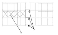
도 4a 은 수직 스티프너(stiffner) 및 대각선 브레이싱(bracing)을 나타내는 모듈 코너의 내부의 부분적인 사시도.
도 4ba 는 강화된 칼럼의 진보적인 대안의 실시예들을 나타내는 3 개의 상부 단면도들의 그룹이다.
도 4bb 는 강화된 칼럼의 진보적인 대안의 실시예들을 나타내는 3 개의 상부 단면도들의 그룹이다.
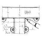
도 5 은 모든 바닥에서 중앙의 복도를 가진 빌딩을 형성하도록 접합된 18개 모듈들의 그룹에 대한 사시도이다.
도 6 은 빌딩을 형성하도록 결합된 모듈들의 그룹에 대한 측면도이다.
도 6a 은 빌딩을 형성하도록 결합된 모듈들의 그룹에 대한 정면도이다.
도 7 는 빌딩에 설치된 슬래브의 단부 및 복도 슬래브의 투시 사시도이다.
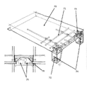
도 8 은 2 개의 연속적인 복도 슬래브들 사이의 연결 지점에서의 복도 바닥과 모듈들의 2 개 적층체들 사이의 연결에 대한 부분적인 분해 사시도이다.
도 9 은 2 개의 결합된 모듈들로 이루어진 잉여의 높은 모듈을 통한 측부 단면도이다.
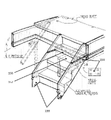
도 10 는 인접한 칼럼들에서의 짝맞춤선의 정면도와 함께 2 개의 적층된 계단 타워 모듈들의 사시도이다.
도 11 은 짝맞춤선에서의 계단의 블라인드 연결(blind connection)에 대한 부분적인 사시도이다.
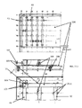
도 12 은 바닥/천장 배치의 핀 배치 및 제작 고정구에 대한 평면도이다.
도 12a 은 바닥/천장 배치 및 제작 고정구의 부분적인 평면도 및 부분적인 측면도이다.
도 12b 는 작업물 위치 핀들(좌측) 및 엘리베이션 블록들의 2 개 실시예들을 나타내는 도면들의 그룹이다.
도 12c 은 통상적인 부재들 사이의 용접부들의 위치에 대한 부분적인 평면도(중앙) 및 간극을 가진 단일 핀의 도면(아래 좌측)이다.
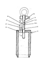
도 13 는 상부 블록의 동체 및 호이스트 피팅(hoisting fitting)에 대한 측면도이다.
도 14 은 호이스트 피팅 및 상부 블록의 사시도이다.
도 15 은 모듈에 맞물린 호이스트 장비(hoisting rig)에 대한 사시도이다.
도 15a 은 전형적인 미끄럼 호이스트 지점에 대한 사시도이다.
도 16 는 전형적인 모듈에 맞물린 것으로 도시된 호이스트 프레임의 부분적인 단부를 나타낸다.
도 17 의 상부는 호이스트 프레임상에서 호이스트 지점을 움직이는 것에 대한 측방향 무게 중심의 효과를 나타내는 평면도이고, 저부 좌측은 조합된 호이스트 지점을 나타내고, 저부 우측은 중심으로부터 일측으로의 무게 중심의 변화에 대한 단부를 나타낸다.
도 17a 은 호이스트 프레임의 하나의 코너에 대한 부분적인 사시도이다.
도 18 는 모듈을 조립하는데 필요한 회전 모듈 조립체 고정구들의 쌍중 하나에 대한 측면도이다.
도 19 는 도 18 의 장치의 플래튼(platen)에 대한 사시도이다.
도 20 은 도 19 의 일부인 위치 선정 정지 랙(locating stop rack)의 부분적인 사시도이다.
도 21 은 분리 칼럼(split column)을 통한 단면도이다.
도 28 은 연장 가능 짝맞춤선 가스켓을 통한 단면도이다.
도 22 는 정면 시스템(facade system)의 분해도이다.
도 24 은 강화된 칼럼들과 구성된 상부 바닥 모듈과 빌트 업 메가 칼럼(built-up mega column)과 구성된 하부 바닥 모듈 사이의 연결에 대한 부분적인 분해도이다.
도 25 은 빌트업 메가 칼럼에 의해 프레임에 이루어진 패널로 구성된 패널 구조체의 수평 단면도이다.
도 26 는 모듈들의 적층체의 정확한 전체 높이 및 정렬을 유지하도록, 변화하는 두께 및 개수의 보강 플레이트의 사용을 나타내는 모듈 적층체의 수직 분해도이다.
도 27 은 모듈들 열(row)의 정확한 전체 폭 및 정렬을 유지하도록, 변화하는 두께 및 수의 쐐기 사용을 나타내는 모듈들의 열에 대한 수평 분해 단면도이다.
유사한 참조 번호들은 상이한 도면들에서 유사한 구성 요소들을 지시하도록 이용된다. Reference is now made by way of example to the accompanying drawings, which show exemplary embodiments of the present invention.
1 is an exploded view of a typical corner connecting block;
1A is a perspective view of a lower corner block;
1B is a side view of the lower corner block showing tapered positioning;
1C is a perspective view of an upper corner block;
2 is a perspective view of a reinforcing plate;
2a is a perspective view of a reinforcing plate joining four columns;
Fig. 2b is a perspective view of a reinforcing plate joining two columns;
3 is a partially exploded perspective view of a module corner;
3a is a partial perspective view of a connection between a stack of two adjacent modules;
Fig. 3b is a vertical section through the arms, the reinforcement plate and the HSS at the connection;
3c is a perspective view of a connection between two modules in a single stack;
3D is a partial side view of a connection between two adjacent stacks of modules;
4 shows the resistance to racking of a corner connection between two adjacent stacks of modules.
4 is an exploded perspective view of the module;
4A is a partial perspective view of the interior of a module corner showing vertical stiffeners and diagonal bracing;
4B is a group of three top cross-sectional views illustrating alternative embodiments of a reinforced column.
Figure 4bb is a group of three top cross-sectional views showing inventive alternative embodiments of a reinforced column;
5 is a perspective view of a group of 18 modules joined to form a building with a central hallway at all floors;
6 is a side view of a group of modules coupled to form a building;
6A is a front view of a group of modules coupled to form a building;
7 is a perspective perspective view of an end of a slab installed in a building and a corridor slab;
8 is a partially exploded perspective view of a connection between two stacks of modules and a corridor floor at a connection point between two successive corridor slabs;
9 is a side cross-sectional view through a redundant tall module of two combined modules;
10 is a perspective view of two stacked stair tower modules with a front view of mating lines in adjacent columns;
11 is a partial perspective view of a blind connection of a step at a mating line;
12 is a plan view of a pin placement and fabrication fixture in a floor/ceiling arrangement;
12A is a partial top and partial side view of a floor/ceiling placement and fabrication fixture;
12B is a group of views showing two embodiments of workpiece locating pins (left) and elevation blocks;
12C is a partial plan view (center) of the location of welds between conventional members and a view of a single pin with a gap (bottom left).
13 is a side view of the fuselage and hoisting fittings of the upper block;
14 is a perspective view of the hoist fitting and upper block;
15 is a perspective view of a hoisting rig engaged with a module;
15A is a perspective view of a typical sliding hoist point;
16 shows a partial end of a hoist frame shown engaged in a typical module;
The top of Figure 17 is a plan view showing the effect of the lateral center of gravity on moving the hoist point on the hoist frame, the bottom left shows the combined hoist point, and the bottom right shows the end for the change of the center of gravity from the center to one side. indicates
17A is a partial perspective view of one corner of the hoist frame;
18 is a side view of one of the pairs of rotating module assembly fixtures required to assemble the module;
FIG. 19 is a perspective view of a platen of the device of FIG. 18 ;
FIG. 20 is a partial perspective view of a locating stop rack that is part of FIG. 19 ;
21 is a cross-sectional view through a split column.
28 is a cross-sectional view through an extendable mating line gasket;
22 is an exploded view of a facade system;
Fig. 24 is a partial exploded view of the connection between the reinforced columns and the configured top bottom module and the built-up mega column and the configured bottom bottom module;
Fig. 25 is a horizontal cross-sectional view of a panel structure composed of panels framed by built-up mega columns;
26 is an exploded vertical view of a stack of modules showing the use of reinforcing plates of varying thickness and number to maintain the correct overall height and alignment of the stack of modules;
27 is a horizontal exploded cross-sectional view of a row of modules showing the use of wedges of varying thickness and number to maintain the correct overall width and alignment of the row of modules;
Like reference numbers are used to designate like elements in different drawings.
상세한 설명은 읽기의 편의를 위하여 구성 요소들의 그룹 또는 각각의 구성 요소에 대한 단락으로 세분되었다.The detailed description is divided into groups of components or paragraphs for each component for convenience of reading.
코너 블록corner block
본 발명은 상부 및 하부 하중 지탱 연결부 또는 블록들을 제공하며, 이들은 하나의 실시예에서 코너 블록(corner block)이다. 특정 실시예에서, 블록들은 실질적으로 4 변형이고, 다른 실시예들에서 다각형 또는 비대칭 형상을 가진다. 이러한 블록들은 대상체의 적은 수 및 크기로 정밀 작업에 집중하기 위하여 그리고 다른 부재들상에서 수행되어야 하는 작업의 복잡성 및 양을 감소시키기 위하여 다양한 기능들을 제공하는 특징부들을 가지고 대량 생산될 수 있다. 상부 및 하부 블록들은 별개의 형태들이고 전체적으로 각도 형태이거나, 튜브 형태이거나, 또는 빌트업(built-up) 형태인 수직 코너 부재(칼럼)들의 상단부 및 하단부상에 위치되는데, 이것은 구성된 모듈들이 대형 구조 또는 높은 구조를 형성하도록 블록상의 특징부들을 이용하여 결합될 때 다층 칼럼(multi-story column)의 기능을 수행한다. The present invention provides upper and lower load bearing connections or blocks, which in one embodiment are corner blocks. In certain embodiments, the blocks are substantially 4 variants, and in other embodiments have a polygonal or asymmetrical shape. These blocks can be mass-produced with features that provide a variety of functions to focus on precision work with a small number and size of objects and to reduce the complexity and amount of work that must be performed on other members. The upper and lower blocks are of separate shapes and are located on the upper and lower ends of vertical corner members (columns) that are generally angular, tubular, or built-up in the form of a large structure or It functions as a multi-story column when combined using features on a block to form a high structure.
마찬가지로 블록상의 다른 특징부들은 빌딩의 수평 부재들과 맞물리고, 그렇게 구성된 모듈들이 대형 또는 넓은 구조물을 형성하도록 접합될 때 연속적인 수평 부재들의 기능을 수행한다. Likewise other features on the block engage the horizontal members of the building and perform the function of successive horizontal members when the modules so constructed are joined to form a large or wide structure.
특정의 실시예에서, 블록들은 블록들의 면에 직각인 것을 포함하지만 그에 제한되지 않는 복수의 각도로 돌출된 테이퍼 아암(tapering arms)을 가지며, 이는 복수개의 각도들에서 인접한 부재들의 위치 및 접합을 제공한다. 특정의 실시예에서, 본 발명은 모듈들의 조립 및 건립을 용이하게 하는데, 이는 직각 형상, 테이퍼 형상, 방사 형상 및 만곡 형상들을 포함하지만 그에 제한되지 않는다. 아암들에 있는 나사 구멍 및 비나사 구멍은 나사 패스너(threaded fasteners)의 위치 선정을 달성하고, 아암들의 수직 벽들은 하중 지탱 용량의 증가를 제공하고, 패스너의 작용 및 빌딩에 작용하는 힘들에 의해 발생된 압축력 및 텐션의 전달을 증가시킨다. In certain embodiments, the blocks have tapering arms projecting at a plurality of angles including, but not limited to, perpendicular to the faces of the blocks, which provide positioning and bonding of adjacent members at a plurality of angles. do. In certain embodiments, the present invention facilitates assembly and erection of modules, including but not limited to rectangular shapes, tapered shapes, radial shapes and curved shapes. Threaded and unthreaded holes in the arms achieve positioning of threaded fasteners, and the vertical walls of the arms provide an increase in load-bearing capacity, generated by the action of the fastener and the forces acting on the building. increased compression and tension transmission.
특정의 실시예에서, 블록들은 볼트의 통과 및 너트로 볼트를 수용하기 위하여 아암 및 동체 양쪽에서 구멍들을 가지거나, 또는 볼트를 수용하도록 나사화되며, 이는 칼럼들을 통한 수직 텐션의 연속성을 제공하고 인접한 모듈들 또는 다른 빌딩 구조들 사이의 모멘트 저항 상호 연결을 제공하기 위한 것이다. 수직 평면에서의 칼럼들의 연결로부터 초래되는 텐션 저항은 구조체가 들어올려짐(uplift)에 저항할 수 있게 하는데, 이것은 수평 평면에서 높은 레벨의 고정성을 가지고 측방향 부재들에 힘을 전달하기 위하여 보강용 플레이트(gusset plate)상에서 발생되고 그곳에 마찰을 발생시킨다. In certain embodiments, the blocks have holes in both the arm and body for passage of the bolt and receiving the bolt into the nut, or threaded to receive the bolt, which provides continuity of vertical tension through the columns and adjacent adjacent blocks. To provide moment-resisting interconnections between modules or other building structures. The tension resistance resulting from the connection of the columns in the vertical plane makes it possible for the structure to resist uplift, which has a high level of fixation in the horizontal plane and is used for reinforcement in order to transmit forces to the lateral members. It occurs on a gusset plate and creates friction there.
보다 상세하게는, 조립하는 동안, 보강용 플레이트에 대하여 지탱되는 HSS 의 내부 표면에 가장 인접한 아암들의 표면들은 모든 공차가 대향하는 단부상에 있으면서 빈틈없이(tight) 만들어짐으로써, 볼트의 작용에 의해 아암들에 부여되는 텐션이 연결 표면들을 압축하고 HSS 를 파쇄하지 않는다. More specifically, during assembly, the surfaces of the arms closest to the inner surface of the HSS bearing against the reinforcing plate are made tight, with all tolerances on the opposite ends, by the action of the bolts. The tension imparted to the arms compresses the connecting surfaces and does not break the HSS.
특정의 실시예에서, 볼트들은 벽의 공동 또는 다른 장소들 안에서 접근 가능하고 표면과 같은 높이 또는 표면 아래에 배치될 수 있어서, 제거 가능한 패치(patch)가 볼트의 위치를 덮도록 용이하게 구성될 수 있고 하중 지탱 구조체를 둘러싸는 내화 재료(fireproofing materials)들의 연속성을 보장할 수 있다. In certain embodiments, the bolts may be accessible within a cavity or other locations in the wall and disposed flush with or below the surface, such that a removable patch may be readily configured to cover the location of the bolt. and ensure the continuity of the fireproofing materials surrounding the load-bearing structure.
특정의 실시예에서, 블록들은 조립 용접을 위한 지원을 제공하도록 위치된 블록의 내부면 및 외부면상의 돌출 특징부들을 가져서, 짧게 절단되거나 또는 정사각형 단부를 벗어나게 절단되거나 또는 다른 불완전성을 가지고 절단된 연결 부재에 대한 용접의 구조적 충격을 감소시킴으로써 작업자가 블록에 용접된 부재들과 코너 블록들 사이에서 부적합의 용접 연결을 수행할 가능성을 감소시키고, 또한 용접부가 표면을 벗어나게 돌출되어 인접한 모듈과 충돌(conflict)할 가능성을 감소시키도록 위치된 블록 외측상의 경사 특징부(beveled feature)를 가진다. In certain embodiments, the blocks have protruding features on the inner and outer surfaces of the block positioned to provide support for assembly welding, so as to be cut short, cut off-square ends, or cut with other imperfections. By reducing the structural impact of the weld to the connecting member, it reduces the likelihood that the operator will make an inappropriate welded connection between the corner blocks and the members welded to the block, and also reduces the likelihood that the weld will protrude off the surface and collide with an adjacent module ( It has beveled features on the outside of the block positioned to reduce the likelihood of conflict.
코너 블록들에 있는 구멍들은 결속(tie-down) 및 호이스트 장치들에 대한 연결의 수단을 제공한다. 특정의 실시예에서, 블록의 상부면에는 개구가 형성되고 개구 안으로 신속 해제 연결구가 삽입될 수 있어서 신속하고 신뢰성 있게 모듈을 리프트 장치(lifting device)에 연결 및 연결 해제시키는 수단을 제공한다. Holes in the corner blocks provide a means of tie-down and connection to hoist devices. In certain embodiments, an opening is formed in the upper surface of the block and a quick release connector can be inserted into the opening to provide a means for quickly and reliably connecting and disconnecting the module to and from a lifting device.
보강용 플레이트reinforcing plate
다른 구성 요소는 칼럼들의 그룹들 또는 칼럼들의 상단부 및 저단부에 있는 블록들 사이에 배치된 플레이트인데, 이것은 상방향으로 향하는 테이퍼진 위치 선정 핀들을 가지며, 상기 핀들은 코너 블록의 하부측에 대응되게 위치된 요부와 미끄럼 접촉됨으로써 하강하는 모듈을 지향시키고 그것과 맞물리기 위한 것으로서, 고정을 위한 정확한 위치에 모듈을 위치시킨다. 플레이트는 또한 건축되는 동안 및 완성된 빌딩에서 수평 평면상의 구조적인 연속성을 제공하도록 볼트로 인접한 모듈들을 연결하는데 이용되는 관통 구멍들을 제공하며, 이러한 연성(ductility) 때문에, 칼럼 길이에서의 약간의 변화를 수용함으로써 그렇게 형성된 칼럼 그룹의 모든 부재들에 동등하게 지탱되는 연속적인 하중 경로를 보장한다. 당업자에게 이해될 수 있는 바로서, 플레이트는 직각으로 또는 다른 배치로 구성된 2 개 이상의 칼럼들 사이 또는 단일의 수직 칼럼 사이에 맞도록 형상화될 수 있다. 특정의 실시예에서 적절한 구멍들을 가지고 제조되고 유사한 치수를 가진 쐐기(shim)들이 연결부의 일측 또는 양측에 배치되어 모듈들의 최종 치수에서의 변화를 수용하고 따라서 모듈 적층체의 정확한 기하 형상을 유지한다.Another component is a plate disposed between groups of columns or blocks at the upper and lower ends of the columns, which have upward-facing tapered positioning pins, the pins corresponding to the lower side of the corner block. For directing and engaging the descending module by sliding contact with the positioned recess, positioning the module in the correct position for fixation. The plate also provides through-holes that are used to connect adjacent modules with bolts to provide structural continuity on the horizontal plane during construction and in the finished building, and because of this ductility, slight variations in column length are avoided. Receiving ensures a continuous load path equally supported on all members of the column group so formed. As will be appreciated by one of ordinary skill in the art, the plate may be shaped to fit between two or more columns configured at right angles or other configurations or between a single vertical column. In certain embodiments, shims of similar dimensions and manufactured with suitable apertures are placed on one or both sides of the joint to accommodate changes in the final dimensions of the modules and thus maintain the correct geometry of the module stack.
계단통(stairwell) 및 엘리베이터 샤프트Stairwell and Elevator Shafts
본 발명의 시스템은 계단 또는 승강 장치들이 내부에 설치되는 모듈들의 조립을 허용하며 모듈들은 현저한 시각적 또는 기능적 혼란 없이 2 개 모듈들 사이의 짝맞춤 선(mateline)에서 분리된다. The system of the present invention allows the assembly of modules into which stairways or hoisting devices are installed and the modules are separated at a mateline between the two modules without significant visual or functional confusion.
**
높이 초과 모듈(overheight modules)overheight modules
본 발명의 시스템은 거주 가능 체적의 상부 절반 및 하부 절반을 포함하는 모듈들의 조립을 허용하는데, 이들은 운송에서의 제한(shipping restriction)이 통상적으로 허용하는 것보다 높고, 현저한 시각적 또는 기능적 혼란 없이 2 개 또는 그 이상의 적층된 모듈들 사이의 짝 맞춤 선에서 접합된다. The system of the present invention allows for the assembly of modules comprising an upper half and a lower half of a habitable volume, which are higher than shipping restrictions typically allow, and are made in two without significant visual or functional disruption. It is joined at mating lines between or more stacked modules.
복도(hallways)hallways
본 발명의 구성 요소들의 다른 그룹은 구조상의 복도 바닥부(structural hallway floor)로서, 이것은 강화 콘크리트, 샌드위치 플레이트, 목재와 같은 적절한 재료로 만들어지거나 또는 지지하는 받침부(pedestal)들과 함께 금속으로 형성된다. 특정의 실시예에서, 슬래브(slab)는 강화 바아들을 가진 강화 콘크리트로 구성되는데 강화 바아(reinforcement bar)들은 받침부들의 굽힘에 저항하기 위하여 지지 받침부상의 특징부가 강화 바아들과 맞물리도록 배치됨으로써, 그렇게 연결된 인접한 모듈들의 적층체 사이에서 모멘트 연결(moment connection)을 형성한다. 받침부에는 상부 및 하부 코너 블록들에 있는 대응 구멍들과 정렬되는 구멍들이 제공되며 이들은 조합된 하중 경로를 생성하기 위하여 일측에 있는 적층체 안에 있는 인접한 칼럼들을 연결할 뿐만 아니라 모듈들의 2 개의 평행한 적층체들을 연결하는 역할을 한다. 받침부 및 바닥 슬래브들은 슬래브의 일측에서 모듈들의 적층체의 단부들 또는 측부들에 연결될 수도 있고 외측에서 발코니 지지 프레임에 연결되어 발코니 또는 브리즈웨이(breezeway)를 가진 빌딩을 형성한다. 바닥 슬래브 및 받침부 조립체들은 도관, 파이프 및 배선과 같은 빌딩 설비를 위한 편리한 캐리어(carrier)로서 이용될 수 있어서 공장 환경의 현장 아닌 곳에서 이들 구성 요소들의 조립을 용이하게 한다.Another group of components of the present invention is the structural hallway floor, which is made of a suitable material such as reinforced concrete, sandwich plate, wood or formed of metal with supporting pedestals. do. In a particular embodiment, a slab is constructed of reinforced concrete with reinforcing bars which are arranged such that a feature on the support abutment engages the reinforcing bars to resist bending of the supports. , forming a moment connection between the stack of adjacent modules so connected. The pedestal is provided with holes that align with corresponding holes in the upper and lower corner blocks, which connect adjacent columns in a stack on one side as well as two parallel stacks of modules to create a combined load path. It serves to connect the bodies. The pedestal and floor slabs may be connected to the ends or sides of the stack of modules on one side of the slab and from the outside to the balcony support frame to form a building with a balcony or breezeway. Floor slab and pedestal assemblies can be used as convenient carriers for building fixtures such as conduit, pipe and wiring, facilitating the assembly of these components off-site in a factory environment.
상호 의존하는 세부 시스템Interdependent detailed systems
본 발명은 또한 미리 결정된 격자(grid)를 포함하며, 빌딩의 상호 연결 요소들의 치수 선정은 고정구들의 시스템(system of fixtures)과 함께 상기 격자에 기초하고, 고정구들은 격자가 모든 조립된 조립체들을 통하여 모든 축들에서 유지되는 것을 보장하며, 이는 모든 축들에서 코너 블록들로부터 부재들, 하위 조립체들, 모듈들 및 전체 빌딩으로 연장된 정확하고 상호 의존적인 관계를 보장한다. 따라서 치수 선정 시스템은 단편적인 요소 및 모듈 크기를 감소시키는 역할을 하여, 공통 부분들의 수를 증가시키고 기초 및 토대 계약자들과의 협동의 어려움을 감소시키며, 이는 그렇게 조립되는 모듈들에서 통합되어야 하는 구성 요소들의 모든 내부 및 외부 공급자들의 작업을 용이하게 한다. The present invention also includes a predetermined grid, wherein the sizing of the interconnecting elements of a building is based on the grid along with a system of fixtures, the fixtures of which the grid is all over all assembled assemblies. is maintained in the axes, which ensures a precise and interdependent relationship extending from the corner blocks to the members, subassemblies, modules and the entire building in all axes. The sizing system thus serves to reduce fragmentary element and module sizes, increasing the number of common parts and reducing the difficulty of cooperating with foundation and foundation contractors, which components must be integrated in the modules so assembled. Facilitates the work of all internal and external suppliers of elements.
특정의 실시예에서, 고정을 위한 구멍들 사이에서 플러스 또는 마이너스 1/32"의 중심 대(對) 중심의 정확도 및, 모든 짝을 이룬 표면들에서 플러스 0" 마이너스 1/16"의 외측 대(對) 외측의 치수 정확도를 가지고, 시스템은 3 개의 축들에서 2 인치보다 작지 않거나 또는 크지 않은 증분(increment)에 기초한다. In certain embodiments, a center-to-center accuracy of plus or
고정구(Fixtures)Fixtures
본 발명은 모듈 프레임들의 조립을 위한 시스템을 포함하는데, 이것은 모듈들이 상기 설정된 격자에 일치하는 것을 보장하고, 또한 모듈의 부분이 최외측의 이상적인 치수를 지나서 돌출되지 않는 것을 보장하며, 이는 조립의 달성 가능한 속도 및 구조체의 정확도를 증가시키고, 추가적인 치수 편차(dimensional drift)의 가능성을 제거하여, 건립의 곤란성의 감소, 내화의 곤란성의 감소, 모듈들을 높은 정도의 고정성을 가지고 상호 연결할 수 있는 가능성 및, 벽 두께와 공간 낭비의 감소를 초래한다. The present invention comprises a system for the assembly of module frames, which ensures that the modules conform to the set grid, and also ensures that no part of the module protrudes beyond the outermost ideal dimension, which achieves assembly Increasing the possible speed and accuracy of the structure, eliminating the possibility of additional dimensional drift, reducing the difficulty of erection, reducing the difficulty of fire resistance, the possibility of interconnecting modules with a high degree of fixation and , resulting in a reduction in wall thickness and wasted space.
테이블 고정구(Table Fixture)Table Fixture
본 발명의 시스템의 구성 요소는 평탄 테이블 또는 피봇 회전이 가능하도록 트러니언(trunion)상에 장착된 평탄 테이블로 이루어진 조절 가능 고정구이며, 이는 충분한 두께를 가지고, 조립 용접을 위하여 바닥 프레임 또는 모듈 천장의 구성 요소들을 지향시키도록 위치된 수직 핀들을 수용하는 구멍들의 격자들과 함께 제조됨으로써, 바닥, 천장 및 벽과 같은 모듈 하위조립체(module subassembly)를 만든다. 위치 선정 구멍들은 모듈들이 위에 확립된 격자에 맞는 것을 보장하도록 배치되며, 이는 다른 빌딩 요소들과 조화됨으로써 그렇게 제조된 모듈들이 용이하게 조립되어 완성된 모듈을 형성하는 것을 보장하고 그리고 완성된 모듈이 빌딩을 형성하도록 조립될 수 있는 것을 보장한다. 핀들에는 스페이서들의 시스템이 설치되는데, 스페이서들은 바닥 또는 천장 표면들의 적용에 필요한 동일 높이의 조건들을 만들기 위하여 조립체의 구성 요소들의 정확한 높이를 보장하는데 이용된다. 고정구는, 용접이 구조 용접에 이상적인 위치에서 수행되는 것을 보장하도록 구성되고 그리고 완성된 부분들이 축적된 공차 조건들을 초래하는 공차 범위(tolerance envelope)를 초과하지 않는 것을 보장하도록 구성된다. A component of the system of the present invention is an adjustable fixture consisting of a flat table or a flat table mounted on a trunion to enable pivot rotation, of sufficient thickness and of a floor frame or module ceiling for assembly welding. Fabricated with a grid of holes receiving vertical pins positioned to orient the components, creating a module subassembly such as floors, ceilings and walls. The positioning holes are arranged to ensure that the modules fit into the grid established above, which ensures that the modules so manufactured can be easily assembled to form a finished module by coordinating with other building elements and that the finished module is built into the building to ensure that they can be assembled to form The pins are equipped with a system of spacers, which are used to ensure the correct height of the components of the assembly to create the necessary flush conditions for the application of floor or ceiling surfaces. The fixture is configured to ensure that the welding is performed in an ideal position for structural welding and to ensure that the finished parts do not exceed a tolerance envelope resulting in accumulated tolerance conditions.
회전 고정구(Rotating fixture)Rotating fixture
본 발명의 다른 구성은 조절 가능하고 회전 가능한 고정구이며, 이것은 조립 용접을 위하여 서로에 대하여 천장 프레임, 바닥 프레임, 코너 칼럼들, 중간 칼럼들, 칼럼 강화부 및 대각선 브레이싱(diagonal bracing)을 지향시키며, 이들 모두는 복수의 치수를 가지고, 이는 모듈들을 위에 확립된 격자에 맞추는 것을 보장함으로써 모듈들의 상호 연결에서의 용이성을 보장하기 위한 것이고, 또한 완성된 부분들이 공차 범위를 초과하지 않는 것을 보장하기 위한 것이며 부분들이 구조 용접의 수행에 이상적인 위치에 지향될 수 있게 보장하는 것이다.Another configuration of the present invention is an adjustable and rotatable fixture, which directs the ceiling frame, floor frame, corner columns, intermediate columns, column reinforcement and diagonal bracing relative to each other for assembly welding, All of them have a plurality of dimensions, to ensure ease in interconnection of modules by ensuring that they fit into the grid established above, and also to ensure that finished parts do not exceed tolerance ranges; It is to ensure that the parts can be oriented in an ideal position for the performance of structural welding.
신속 연결 호이스트 커넥터quick connect hoist connector
본 발명의 다른 구성은 해제 가능하고 집약적인 신속 커넥터(quick connector)로서, 이것은 호이스트 장치(hoisting apparatus)를 모듈에 부착시키는데 채용되고, 코너 블록들에 있는 특별히 준비된 개구 안에 공구 없이 위로부터 설치되며, 우발적으로 해제되는 것에 저항하고, 공구 없이 제거될 수 있다. 특정의 실시예에서, 토글(toggle)의 상방향으로 향하는 베어링 표면 및 수용 블록의 대응되게 하방향으로 향하는 베어링 표면과 하중을 베어링 표면으로부터 호이스트 장치로 이송시키는 토글 샤프트(toggle shaft) 의 텐션 부하 부분(tension loaded part)은, 코너 블록의 상부면내에 조립의 치수 한계를 유지하면서 가장 콤팩트한 공간내에 조합된 요소들의 하중 지탱 용량을 최대화시키기 위하여, 이상적으로 비례한다. Another configuration of the present invention is a releasable and integrated quick connector, which is employed to attach a hoisting apparatus to a module and is installed from above without tools in specially prepared openings in the corner blocks, Resists accidental release and can be removed without tools. In certain embodiments, the upward facing bearing surface of the toggle and the corresponding downward facing bearing surface of the receiving block and the tension loading portion of the toggle shaft transferring the load from the bearing surface to the hoisting device The tension loaded part is ideally proportional in order to maximize the load-bearing capacity of the combined elements in the most compact space while maintaining the dimensional limits of assembly within the upper surface of the corner block.
호이스트 프레임(hoisting frame)hoisting frame
본 발명의 다른 구성 요소는 호이스트 장치로서, 이것은 빌딩 안의 배치를 위한 이상적인 자세로 하중을 매달도록 구성되며, 특정의 실시예에서 수평이고, 모든 연결 지점들의 위치에 대한 신속한 조절을 제공하는데, 모듈의 길이에서 발생되는 무게 중심의 차이를 보상하기 위하여 상기 연결 지점들로부터 크레인 후크(crane hook)로 라인들이 통과된다. 설명된 장치는 프레임의 일측에서 케이블 쌍들 사이의 벌어짐을 변경할 수 있게 하여 모듈의 일측에 있는 크레인 후크로 통과되는 라인들의 쌍의 수직으로부터의 매달림 각도를 변화시키는데, 이는 프레임의 장축(long axis)의 일 측에 대한 크레인 부착의 중심을 이동시킴으로써 그로부터 매달린 모듈의 폭에서 발생되는 하중의 무게 중심 변화를 보상하기 위한 것이다. Another component of the present invention is a hoist device, which is configured to suspend a load in an ideal position for placement in a building, is in a particular embodiment horizontal, and provides for quick adjustment of the position of all connection points of the module. Lines are passed from the connection points to the crane hook to compensate for the difference in the center of gravity caused by the length. The device described makes it possible to change the splay between the pairs of cables on one side of the frame, thereby changing the angle of suspension from the vertical of the pair of lines passed to the crane hook on one side of the module, which is the length of the long axis of the frame. This is to compensate for the change in the center of gravity of the load generated in the width of the module suspended therefrom by moving the center of the crane attachment to one side.
강화 부재(Reinforcing members)Reinforcing members
또한 본 발명은 표준화된 강화 부재들의 시스템을 포함하는데, 이것은 서로 연결되고, 또한 여기에 설명된 칼럼들, 측방향 프레임(lateral framing), 대각선 브레이싱 및 코너 블록들과 연결됨으로써, 강화 구성부들의 경우에 따른 설계(case-by-case design) 및 제작 또는 주문 제작을 제거한다.The invention also comprises a system of standardized reinforcing elements, which are connected to each other and also connected to the columns, lateral framing, diagonal bracing and corner blocks described herein, thereby in the case of reinforcing components. Eliminate case-by-case design and fabrication or customization.
강화 해석(Reinforcement analysis)Reinforcement analysis
본 발명은, 모듈들로 구성된 빌딩에 작용하는 힘들을 시스템적으로 해석하고, 표준화된 강화 시스템들의 적용을 위한 최적의 위치를 한정하고, 점진적인 버클링(progressive bucking) 및 업리프트(uplift) 저항성을 가진 표준화된 강화부들의 목록으로부터 선택하고, 추가적인 스트레스 하에 있는 영역들을 강화시키는데 최소한으로 필요한 바로서 오직 그러한 강화부들을 포함시키는 작업 방법을 포함하며, 이것은 필요한 것보다 더 많은 위치들에 불필요한 구조 재료를 추가하지 않으면서, 내화 재료의 적용을 현저하게 혼란시키지 않으면서, 그리고 모듈 벽의 추가적인 두께를 요구하지 않으면서 이루어진다. The present invention systematically analyzes the forces acting on a building composed of modules, defines an optimal location for the application of standardized reinforcement systems, and provides progressive bucking and uplift resistance. Selecting from a list of standardized reinforcements having a working method that includes only those reinforcements as minimally necessary to strengthen areas under additional stress as are necessary, which include placing unnecessary structural material in more locations than necessary. This is done without adding, without significantly disrupting the application of the refractory material, and without requiring an additional thickness of the module walls.
빌트 업 칼럼(Built up columns)Built up columns
또한, 본 발명은 외측 칼럼들의 조립 및 연결을 위한 방법을 포함함으로써, 외측 칼럼들은 고층 빌딩 및/또는 가느다란 빌딩(slender building)의 건축에서 발생되는 하중들로부터 초래된 압축력 및 장력에 대하여 커다란 저항성을 가진 그룹을 형성한다. The present invention also comprises a method for assembling and connecting outer columns, whereby the outer columns are highly resistant to compression and tension resulting from loads arising in the construction of high-rise and/or slender buildings. form a group with
연장 가능 가스켓(Extendable gasket)Extendable gasket
더욱이, 본 발명은 호이스트 및 배치(hoisting and placement) 작용중에 기스켓 표면에 대한 손상을 방지하기 위하여 모듈이 작용에 의해 배치된 이후에 다른 대향하는 가스켓과 만나도록 연장되는 가스켓을 포함한다. Furthermore, the present invention includes a gasket that extends to meet another opposing gasket after the module is placed by action to prevent damage to the gasket surface during hoisting and placement action.
장점Advantages
프레임 없는 높이 증가Frameless height increase
본 발명의 작업 방법 및 구성 요소들의 시스템은, 그렇게 형성되고 연결된 모듈 빌딩 유닛들 전체를 포함함으로써, 부차적인 외부 또는 내부 브레이싱 프레임에 대한 필요성 없이 건설될 수 있는 빌딩 높이를 증가시키는 역할을 하고, 또한 사용 가능한 바닥 면적을 증가시키는 역할을 하는데, 이는 부재들의 많은 부분이 구조 기능 및 향상된 연결의 고정성에 포함되고, 다수이고 여분의 하중 경로들이 형성되고 보장되며, 브레이스 프레임이 모듈 벽들에 통합되고, 그리고 결과적으로 완성된 빌딩에 부과되는 외부, 내부 및 자체 하중들이 인접한 모듈들을 통해서 그리고 따라서 지면으로 효과적으로 전달되기 때문이다. The working method and system of components of the present invention serve to increase the height of a building that can be built without the need for an additional external or internal bracing frame, by including all of the modular building units so formed and connected, and also serves to increase the usable floor area, where a large part of the members are incorporated into the structural function and the improved stability of the connection, multiple and redundant load paths are formed and ensured, the brace frame is integrated into the module walls, and As a result, external, internal and self-loads imposed on the finished building are effectively transmitted through adjacent modules and thus to the ground.
프레임에 의한 높이 증가(Increases height with frame)Increases height with frame
상부 바닥에서 필요한 철(steel)의 양을 감소시키고 따라서 전체 중량을 감소시킴으로써, 본 발명은 주어진 크기의 부차적인 외부 또는 내부 브레이싱 프레임을 사용함으로써 지어지는 빌딩의 높이를 증가시키는 역할을 한다. By reducing the amount of steel required in the upper floor and thus reducing the overall weight, the present invention serves to increase the height of a building being built by using a secondary external or internal bracing frame of a given size.
특이 부분들의 수, 위치들의 수 및 부재들의 크기 감소(Reduces number of unique parts, number of locations and size of members)Reduces number of unique parts, number of locations and size of members
가해지는 하중을 해석하고 구조 기능에서 필요한 더 많은 부재들을 더 효율적으로 포함시킴으로써, 본 발명은 필요한 부재들의 크기를 감소시키고, 특이한 강화부의 세부 사항(reinforcement detail) 및 내화재(fireproofing)의 관련된 복잡성이 필요한 곳의 위치, 크기 및 수를 제한하며, 그에 의해 그러한 빌딩의 비용을 감소시킨다. By interpreting the applied load and more efficiently including more members required in the structural function, the present invention reduces the size of the required members, requiring specific reinforcement details and the associated complexity of fireproofing. Limit the location, size and number of places, thereby reducing the cost of such buildings.
정밀 요건의 감소(Reduces requirement for precision)Reduces requirement for precision
본 발명은 모듈 제조 설비에서 작업자들에 의해 만들어져야 하는 부분들의 정밀도를 감소시키며, 이는 제조 비용을 절감시킨다. The present invention reduces the precision of parts that have to be made by operators in a module manufacturing facility, which reduces manufacturing costs.
복잡한 제조의 감소(Reduces complex fabrication)Reduces complex fabrication
본 발명은 부재들을 결합시키고, 모듈을 끌어올리고, 모듈들을 단일의 대량 생산 구성으로 결합시키는데 필요한 많은 복잡한 특징들에 집중하여, 모듈을 구성하는데 필요한 숙련 작업에 대한 필요성 및 복잡성 모두를 감소시킨다. The present invention reduces both the complexity and the need for the skilled work required to construct the module by concentrating on the many complex features required to join the members, lift the module, and combine the modules into a single mass production configuration.
높이 및 넓이의 허용(Allows taller and wider)Allows taller and wider
추가적으로 이러한 시스템은 2 개의 적층된 프레임들로 구성된 높은 모듈들을 구성할 수 있게 하는데, 모듈들중 하나는 천장에 개구를 가지고 다른 하나는 바닥에 개구를 가지며, 브레이싱(bracing)의 수행에 기인하여 긴 모듈들이 이루어지고, 단부들에 있는 통공들의 향상된 거동에 기인하여 넓은 모듈들이 이루어져서, 그렇게 건설되는 빌딩들의 설계자들에게 더 큰 융통성을 제공한다. Additionally this system makes it possible to construct tall modules consisting of two stacked frames, one of the modules having an opening in the ceiling and the other having an opening in the floor, the length of which is due to the performance of bracing. Modules are made, and wide modules are made due to the improved behavior of the apertures at the ends, providing greater flexibility to the designers of the buildings so constructed.
벽 두께의 감소(Reduces wall thickness)Reduces wall thickness
하중 지탱 구성 요소들을 보다 완전하게 분포시킴으로써, 본 발명은 구조 및 서비스를 수용하는데 필요한 벽 두께를 감소시킨다. By more fully distributing the load-bearing components, the present invention reduces the wall thickness required to accommodate structures and services.
보수를 위한 현장 노동의 감소(Reduces site labour for patching)Reduces site labor for patching
벽 공동내의 텐션 연결을 배치하고 칼럼에 인접한 연결 수단에 집중함으로써, 본 발명은 차후에 보수되어야만 하는 빠트린 영역(leave-out area)의 범위 및 수를 감소시킬 수 있다. By locating the tension connections in the wall cavity and concentrating on the connection means adjacent to the column, the present invention can reduce the number and extent of leave-out areas that must be repaired later.
건설중에 가스켓 손상의 제거(Eliminates gasket damage during erection)Eliminates gasket damage during erection
수축 위치에 있다가 건설 이후에 연장되는 가스켓을 가지는 모듈들을 운송(shipping)하고 건설함으로써, 본 발명은 가스켓에 대한 손상 가능성을 감소시키고, 빌딩 엔벨로프(building envelope)의 수반하는 성능 감소를 줄인다.By shipping and building modules that have gaskets that are in a retracted position and extend after construction, the present invention reduces the potential for damage to the gaskets and reduces the attendant performance degradation of the building envelope.
명세서에 개시된 실시예에 따라서 본 발명은 이제 첨부된 도면을 참조하여 설명될 것이다.The invention according to the embodiments disclosed in the specification will now be described with reference to the accompanying drawings.
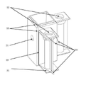
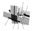
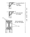
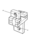
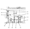
도 1 은 연결구 조립체(1)로서, 이것은 상부 연결구(10) 및 하부 연결구(20)를 가지고 보강 플레이트(30)와 함께 도시되어 있다. 1 is a
도 1 은 연결구 조립체(1)의 실시예를 개시하는데, 이것은 상부 연결구(10), 하부 연결구(20) 및, 상기 상부 연결구(10)와 하부 연결구(20) 사이에 개재된 보강 플레이트(30)로 이루어진다. "상부" 및 "하부"와 같은 용어들은 상대적이며 서로 대체될 수 있다. 그러나, 연결구 조립체(1)를 설명할 목적으로, 상부 연결구(10)는 제 2 (또는 하부) 모듈 프레임상에 위치되고 들어올려질 수 있는, 모듈 프레임의 상부 단부 또는 상부 코너에 통상적으로 위치될 연결구를 지칭한다. 하부 연결구(20)들은 모듈 프레임의 하부 단부 또는 하부 코너상에 위치되는 연결구를 지칭하며, 그것은 (상부 연결구보다) 지면 또는 바닥에 더 인접한다. 1 discloses an embodiment of a connector assembly (1) comprising an upper connector (10), a lower connector (20) and a reinforcing plate (30) interposed between the upper coupler (10) and lower connector (20). is made of Terms such as "upper" and "lower" are relative and may be substituted for each other. However, for purposes of illustrating the
도시된 실시예에서, 상부 코너 연결구(10) 및 하부 코너 연결구(20)는 강철의 중공형 주물(hollow casting)로부터 만들어질 수 있다. 더욱이, 상부 연결구(10)는 칼럼, 기둥 또는 모듈 프레임의 다른 구조 유닛을 수용하기 위하여 형성된 개구를 일 단부(제 1 단부(2))에 가지며, 따라서 상부 연결구는 제 1 모듈 프레임의 단부에 결합될 수 있다. 상부 연결구(10)의 제 2 단부(3)는 상부 연결구(10)를 보강 플레이트(30)에 결합할 수 있도록 설계된다. 하부 연결구(20)에는 제 1 단부(4) 및 제 2 단부(5) 양쪽에 개구가 제공될 수 있고; 보강 플레이트(30)에 결합되도록 적합화된 제 1 단부(4)가 제공되는 반면에, 제 2 단부(5)는 제 2 모듈 프레임의 코너 또는 단부에 결합될 수 있다. 연결구들은 연강(mild steel)과 동등하거나 또는 그보다 큰 연성(ductility) 및 인장 강도와 같은 기계적인 특성을 가질 수 있고 또한 연결구들이 구조 금속 불활성 기체(MIG) 용접과 같은 표준적인 실행으로 연강에 용접될 수 있는 야금학적 특성을 가질 수 있다. In the illustrated embodiment, the
다른 실시예에서, 상부 및 하부 연결구(10,20)는 중공형 동체(2,4)를 각각 가진다. 상부 연결구의 중공형 동체(2) 및 하부 연결구의 중공형 동체(4)는 설계 및 적용 요건들에 따라서 다양한 형상들을 가질 수 있다. 그러나, 도면에서, 상부 및 하부 연결구(10,20)는 정사각형 단면을 가진 형상을 구비한 중공형 동체(2,4)를 포함한다. 돌기(6)는 상부 연결구(10)의 중공형 동체(2)의 외측 표면상에 제공된다. 유사한 돌기(18)가 하부 연결구(20)의 중공형 동체(4)의 외측 표면상에 제공된다. In another embodiment, the upper and
상부 연결구(10)는 돌기(18)들로부터 연장된 적어도 한 쌍의 아암(11)들에 의해 제공된다. 하부 연결구(20)에는 돌기(18)로부터 연장된 적어도 한쌍의 아암(11)들이 제공된다. 도시된 실시예에서, 아암(11)들은 통상적으로 돌기(18)의 표면으로부터 연장된다. 또한, 아암(11)들은 서로 직각으로 위치되며, 즉, 하나의 아암은 제 1 아암에 대하여 거의 90°로 연장된다. 그러나, 아암(11)들의 위치는 설계 및 적용 요건들에 따라서 변화될 수 있고, 아암(11)들은 90°보다 크거나 작은 각도로 존재할 수 있다. 상부 연결구(10)상의 아암(11)들에는 통공(12)들이 제공될 수 있는데, 상기 통공들은 상부 또는 하부 연결구를 연결구 조립체(1)에 결합시키는데 이용될 수 있다. The
일 실시예에서, 중앙의 중공형 동체(2,4)들은 4" x 4" 중공형 구조 섹션(Hollow Structural Section;HSS)을 받아들이는 4" 정사각형이다. 다른 실시예에서, 중앙의 중공형 동체(2,4)들은 6"x 6" HSS 를 받아들이는 6" 정사각형(square)이다. 연결구(10,20)들은 주조를 용이하게 하는 섹션의 균일성 및 드래프트 각도(draft angle)과 같은 의도된 기능 및 세부 내용을 위하여 적절한 두께를 가진다. 특정의 실시예에서, 아암(11)들의 위치 선정 표면들과 통공(12)들의 중심들 사이에서 측정된 바로서 +0 내지 -0.010 인치의 정밀도로 표면들이 밀링되고 주물이 드릴되거나, 편의에 따라서 다른 공차들이 이용된다. 다른 실시예에서, 연결구는 하나 이상의 롤링된 섹션(rolled section)들을 조립함으로써 만들어지고, 용접 또는 다른 기계적 수단에 의해 평탄하거나 또는 브레이크-형성(brake-formed) 플레이트를 조립함으로써 만들어진다. 다른 실시예에서, 부품들은 비철, 플라스틱, 세멘트 재료(cementitious material) 또는 그 어떤 다른 적절한 재료를 캐스팅함으로써 만들어진다. 다른 실시예에서, 칼럼 및 아암들이 연결될 블록들의 부분들은 HSS 를 위치시키고 용접을 용이하게 하는 특징부들을 가질 수 있다. In one embodiment, the central
연결구 조립체(1)는 상부 연결구(10)와 하부 연결구(20) 사이에 보강 플레이트(30)를 개재시킴으로써 형성될 수 있다. 도시된 보강 플레이트(30)는 2 개의 면들을 가지는데, 제 1 면은 하부 연결구(20)와 접촉될 수 있고, 제 2 면은 상부 연결구(10)와 접촉될 수 있다. 또한, 보강 플레이트(30)에는 관통 구멍(31)들이 제공되며, 이들은 상부 연결구(10) 및 하부 연결구(20)상의 통공(12)들과 정렬되어, 고정 수단을 이용하여 연결구(10,20)의 고정을 용이하게 한다. 고정 수단은 특히 제한되지 않으며, 너트 볼트 스크류를 포함할 수 있다. The
도 1a: 하부 연결구(20)1a:
*하부 연결구는 돌기(18)들을 가지며, 이들은 모듈 프레임의 길이 방향 부재 및 횡방향 부재들에 위치를 제공하고 조립체 용접을 위한 지지(backing)를 제공한다. 도시된 실시예에서, 상부 연결구 및 하부 연결구의 중공형 동체의 가장자리들은 경사진 가장자리(beveled edges)를 가진다. 경사부(19)는 용접 비드(weld bead)의 외부 표면에 대한 위치를 제공하는데, 이는 용접이 같은 높이에 있게 하고 연결된 부재를 경사지게 하는 필요성을 제거한다. 하부 커넥터(20)의 외측면들은 복수개 구멍(또는 보어(bore))(21)들을 가질 수 있으며, 이들 구멍들은 볼트, 핀, 클립, 결합용 플레이트 또는 다른 고정 수단의 사용을 통하여 칼럼 그룹, 복도 슬래브(hallway slab), 고정구, 호이스트 수단 또는 다른 유용한 특징부들과의 연결에 이용되도록 환경에서 필요한 바에 따라 나사화되거나 또는 나사화되지 않는다. 다른 실시예에서, 연결구(20)는 4 개 보다 많거나 적은 측부를 가지고 4 변형은 아니며, 그러나 부등변 사각형 또는 평행 사변형 또는 다른 형상을 가지며, 이는 둥글거나, 만곡되거나, 테이퍼지거나, 별 형상이거나 또는 다른 빌딩 형태의 생산을 용이하게 하기 위한 것이다. *The bottom connector has
하부 연결구(20)는 텐션 볼트(tension bolt, 25)들의 통과를 위한 구멍(또는 통공)(12)들을 가진 아암(11)들을 구비하며, 텐션 볼트는 보강 플레이트(30)를 통과하여 모듈을 수직으로 고정시키고 연속적인 텐션 및 모멘트 연결(moment connection)을 제공하며, 이는 수평 비임들과 적층된 칼럼들 사이의 연결을 통하여 하중을 통과시킨다. 다른 실시예에서, 상기 아암들은 표면에 직각으로 돌출되고, 다른 실시예에서 테이퍼진 측부(22)를 가짐으로써 각도를 두고 부재들의 연결을 허용하며, 다른 실시예에서 아암들 전체는 각도를 두고 돌출된다. The
도 1b: 하부 연결구(20)1b:
하나의 실시예에서, 연결구(20)는 도 1b 에 도시된 치수들을 가진다. 점선으로 도시된 바와 같이 저부면은 개구를 가지며, 그것의 측부들은 저부면(23)에 대하여 테이퍼지거나 또는 직각이다. 모듈 중심에 대하여 방사상의 관계를 가지는 모듈상의 복수개의 개구들은 보강 플레이트(30)에 있는 대응되고 테이퍼진 위치 선정 핀(33)을 아래에서 수용하며, 따라서 모듈을 아래에 있는 모듈의 상부에서 연결을 위한 정확한 위치에 위치시킨다. In one embodiment, the
도 1c: 상부 연결구(10)1c: upper connector (10)
상부 코너 연결구(10)는 돌기(18)들을 가지며, 돌기들은 모듈 프레임의 길이 방향 부재 및 횡방향 부재들에 대한 위치를 제공하고 조립 용접을 위한 지지를 제공한다. 하부 연결구(20)와 유사하게, 도시된 실시예에서, 상부 및 하부 연결구들의 중공형 동체의 가장자리는 경사진 가장자리를 가진다. 경사부(19)는 외부 용접 비드(weld bead)를 위한 위치를 제공하며, 이것은 용접부가 같은 높이에 놓이게 하고 연결된 부재를 경사지게 할 필요성을 제거한다. 블록(10)의 외측면들은 복수개의 구멍들(또는 보어들)(21)을 가지는데, 이들은 볼트, 핀, 클립, 결합 플레이트 또는 다른 고정 수단의 사용을 통해 칼럼 그룹, 복도 슬래브 또는 다른 유용한 특징부들의 연결에서 이용되도록 환경에서 요구되는 바에 따라서 나사화되거나 또는 나사화되지 않는다. 다른 실시예에서 블록은 높고, 추가적인 구멍들이 추가적인 패스너들의 사용을 위하여 또는 추가적인 브레이싱 또는 다른 특징부들의 추가를 위하여 제공된다. 다른 실시예에서 블록은 4 개 보다 많거나 적은 측면을 가지며 4 변형이 아니고, 그러나 부등변 사각형, 평행 사변형 또는 다른 형상을 가지는데, 이는 둥글거나, 만곡되거나, 테이퍼지거나, 별 형상이거나 또는 다른 빌딩 형태의 제조를 용이하게 하기 위한 것이다. 다른 실시예에서 이들 아암들은 표면에 직각으로 돌출되고, 다른 실시예에서 이들은 각도를 두고 부재들의 연결을 허용하도록 테이퍼진 측부(22)들을 가지며, 다른 실시예에서 아암들 전체는 각도를 두고 돌출된다.
또 다른 실시예에서, 상부 연결구(10)는, 텐션 볼트(25)들의 수용을 위하여 블록의 동체에 가장 근접한 나사 구멍들(또는 제 2 통공)(12) 및, 보강 플레이트 스크류(34)의 수용을 위하여 블록으로부터 가장 멀리 있는 나사 구멍들(또는 제 1 통공)(13)을 가진 아암(11)들을 구비한다. 특정의 실시예에서 이들 아암들은 표면에 직각으로 돌출되고, 다른 실시예에서 이들은 각도를 두고 부재들의 연결을 허용하도록 테이퍼진 측부(22)들을 가지며, 다른 실시예에서 아암들 전체는 각도를 두고 돌출된다. In another embodiment, the
블록의 상부면은 T 형상 구멍(14)을 가지며, 이것은 여기에 설명되고 도 13 및 도 14 에 도시된 바와 같이 강철 리프트 피팅(lifting fitting, 15)과 맞물린다.The top surface of the block has a T-shaped
도 2: 보강 플레이트(30)Figure 2: Reinforcing
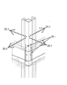
일 실시예에서, 보강 플레이트(30)는 적절한 두께 및 의도된 기능을 위한 기계적 특성을 가진 강철 플레이트 또는 다른 재료로부터 절단된다. 다른 실시예에서, 두께는 3/8" 이다. 보강 플레이트는 관통 구멍(31), 카운터싱크 구멍(countersunk hole, 32) 및 위치 선정 핀(33)을 가진다. 상부 연결구(10)에 있는 구멍(13) 안으로 나사 결합되고 구멍(32)을 통과하는 평탄 헤드 스크류(34)는 인접한 칼럼들을 정확하게 결합시키고 따라서 전체 모듈들을 결합시킨다. 수직 평면에서의 플레이트(30)의 연성(ductility)은 칼럼 그룹들이 큰 하중을 견디도록 함께 작용하는 것을 보장한다. 평탄 헤드(flathead) 스크류들을 위한 구멍(32)들 및 연결구들에 있는 대응 구멍들의 위치의 정밀성은 모듈-대(對)-모듈의 공차가 유지되고 제어되는 것을 보장한다. In one embodiment, the reinforcing
보강 플레이트(30)는 1개, 2개, 3개, 4개 또는 그 이상의 칼럼들의 상부에 맞는 크기를 가질 수 있어서 모든 위치들에서 등가의 수직 분리를 제공하고, 2 개, 3 개, 4 개 또는 그 이상의 모듈들의 그룹을 형성한다. 도 2a 에 도시된 바와 같이 보강 플레이트가 4 개의 모듈들을 결합시키는 실시예를 개시하는 반면에, 도 2b 는 2 개의 모듈들을 결합하는 보강 플레이트(30)를 2 개의 모듈들을 결합하는 보강 플레이트(30)를 개시한다. 도 2b 에 도시된 보강 플레이트(30)의 실시예에서, 여기에 더 개시되는 바와 같이 플레이트에는 인접한 구성 요소의 지지를 위한 돌출 가장자리가 제공된다.
도 3: 모듈의 조립Figure 3: Assembly of the module
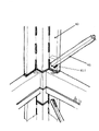
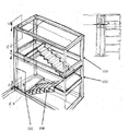
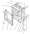
모듈의 바닥 프레임을 형성하도록, 길이 방향 바닥 비임(41) 및 측방향 바닥 비임(42)은 길이로 절단되고, 이들에는 구멍(43)들이 제공되며, 상기 구멍들은 연결구(10)의 아암(11)들에 있는 구멍들의 위치들에 전체적으로 대응하지만 그것과 간섭하지 않는다. 특정의 실시예에서, 상기 비임들은 주변(perimeter)을 위한 3" x 8" HSS 및, 충전 부재(infill member)를 위한 3" x 6" HSS 이다. 여기에 설명된 위치 선정 및 용접 고정구(도 17)는 미리 기계 가공된 연결 블록들을 위치시키고 구멍 위치를 한정하기 때문에, 그리고 서로에 대한 이들의 위치들은 조립의 외부 치수들을 제공하기 때문에, 고정구(fixture)는 고정구를 이용하여 제작된 모듈들이 이전에 설명된 확립된 격자에 맞는 것을 보장한다. 또한, 비임들이 단부들의 가장자리에서 경사(beveling)를 필요로 하지 않는 것과, 길이로의 절단 작용이 길이 또는 정사각형에서 중요하지 않은 것을 블록들상의 특징부들이 보장한다. 비임들은 하부 코너 연결구(20)상에서 대응하는 아암(11)들에 걸쳐 미끄러지며 이전에 설명된 방식으로 용접된다. To form the bottom frame of the module, the longitudinal
당업자는 천장의 조립이 동일한 고정구에 배치된 적절한 크기의 부재들을 이용하는 유사한 과정을 따른다는 점을 인식하여야 한다. 특정의 실시예에서, 이들은 주변을 위한 3" x 3" HSS 및 충전 부재를 위한 2" x 2" HSS 이다. 따라서 상부 및 저부 프레임들 양쪽은 동일한 고정구의 외측 치수를 가지고 상부 및 저부 프레임들 양쪽은 조화된다. Those skilled in the art should recognize that the assembly of the ceiling follows a similar procedure using appropriately sized members disposed on the same fixture. In certain embodiments, these are 3" x 3" HSS for the perimeter and 2" x 2" HSS for the filling member. Thus both the top and bottom frames have the same outer dimensions of the fixture and both the top and bottom frames are matched.
섬유-시멘트 보드(fibre-cement board), 또는 강철 시트 덱크 및 콘트리트 상부(concrete toping), 또는 강철-복합 시트 덱킹(decking)과 같은 적절한 재료(44)가 모듈 바닥의 바닥 비임들의 상부면에 적용되어 구성되고 적절하게 고정되거나, 또는 콘크리트 또는 다른 재료가 프레임 사이에 채워지는데, 이는 점유된 하중을 지지하고 필요한 다이아프램 작용(diaphragm action)을 모듈에 제공하고 다시 모듈들로 구성된 빌딩에 제공하기 위한 것이다. 마찬가지로, 조건에 따른 다양한 유형의 절연체 및 내화 보드 또는 드라이월(drywall)과 같은 재료가 프레임 및 보드의 표면들과 벽 및 천장들 안의 공동에 적용되어, 점유자들의 프라이버시, 구조물의 내화 작용(fireproofing)의 제공 및 음의 전달 제한과 같은 다양한 기능을 제공한다. A
도 3a, 도 3c, 도 3d, 도 3e: 모멘트 저항 구조를 형성하는 모듈들의 수직 연결3a, 3c, 3d, 3e: vertical connection of modules forming a moment resistance structure
이전에 설명된 바와 같이, 하부 연결구 튜브(41)는 아암(22)에 있는 구멍과 소통되는 오버사이즈 구멍(oversize hole, 43)들을 가지며, 텐션 볼트(25)가 상기 구멍을 통과하여 상부 벽 프레임 튜브(45) 내부에 있는 상부 블록(10)상의 아암(11)의 상부면에 있는 나사 구멍과 나사 결합되어, 보강 플레이트(30)를 포착 및 클램핑하고 수직 텐션 하중을 연결을 통해 전달한다. As previously described, the
텐션 볼트(25)는 정확한 토크 값으로 아래에 있는 모듈의 상부 연결구(20)상의 아암(11)의 구멍(12)내 암나사에 결합되므로, 발생된 텐션은 상부 및 하부 프레임 튜브들 및 보강 플레이트를 함께 당김으로써 연속적인 모멘트 작용(25.1)이 확립되며, 상기 모멘트 작용(moment action)은 그렇게 형성된 연결을 통하여 칼럼으로부터 칼럼으로 통과되고, 그리고 인접한 프레임 튜브들, 특히 바닥 프레임을 포함하는 깊은 부재(deeper member)들에 의하여 수직 평면에서 회전되는 것이 방지된다. 바람, 지진 및 다른 하중을 겪는 모든 빌딩들의 특징인 랙킹 작용(racking action)은 그렇게 감소된다. 특정의 실시예에서, 볼트(25)들은 Grade 8 과 같은 고강도 강철로 구성됨으로써 볼트들의 수 및 인장 강도의 조합은 그렇게 연결된 구조체상에 바람 또는 지진으로 유발된 상승에 저항하기에 충분하다. The
도 4: 통상적인 프레임의 분해도Figure 4: Exploded view of a typical frame
바닥 프레임(40)은 코너 칼럼(50) 및 중간 칼럼(51)들에 의해 천장 프레임(47)에 연결되는데, 특정의 실시예에서 이들은 바닥 및 천장 프레임들에 실질적으로 직각이고 제 위치에 용접된다. 다른 실시예에서 상부 및 하부 수평 부재들과 중간 수직 칼럼(48)들 사이의 연결은 도 1a 및 도 1c 에 설명된 연결구들과 형태가 유사하지만 대향하는 아암들을 가진 중간 연결구(49)로써 구성된다. 다른 실시예에서 칼럼들은 다양한 길이를 가지고 서로에 대하여 또는 블록들에 대하여 맞도록 연귀 이음(mitred)됨으로써 천장과 바닥 사이의 복수의 각도 관계들이 구현된다. The
도 4a: 측벽 브레이싱(sidewall bracing)의 도면Figure 4a: a diagram of sidewall bracing
만약 모듈에 작용하는 하중이 대각선 강화의 추가를 보장할 정도로 충분히 크다면, 도 4a 에 도시된 굳게 하는(rigidifying) 대각선 브레이싱 시스템(diagonal bracing system)이 설치된다. 대각선 강화 시스템은 수직 강화 바아(60)들로 이루어지는데, 이것은 특정의 실시예에서 도 4a 에 도시된 위치에 설치되고 그에 도시된 형태이거나 또는 도 4ba 또는 도 4bb 에 도시된 다른 특정 실시예들의 위치에 설치되고 그에 도시된 형태이다. 대각선 바아(61)들은 이들 부재들에 용접 또는 볼트 결합되거나, 또는 작은 하중을 가지는 가벼운 구조체들의 경우에, 수직 또는 수평 프레임 부재들에 직접 용접되거나 또는 이들 양쪽 모두에 직접 용접된다. 그렇게 형성된 모듈은 도 4 에 설명된 모멘트-저항 코너 연결에 의해 다른 모듈들에 연결되었을 때 모멘트 및 텐션 저항 구조를 형성하며, 이것은 하중을 모든 축들에서 그 자체를 통하여 전달한다. 특정의 실시예에서, 바아들은 대각선으로 대향되고 섹션이 3/4" 이고 텐션을 받으면서 기능한다. 다른 실시예에서 이들은 대각선으로 대향되고 섹션이 1" x 3" 이고 텐션을 받으면서 기능한다. 다른 실시예에서 이들은 단일의 바아이고 3" x 4" HSS 이거나 또는 다른 치수를 가지며,이들이 저항하는 하중들에 적절한 바로서 압축 및 텐션 모두를 받으면서 기능한다. If the load acting on the module is large enough to ensure the addition of diagonal reinforcement, a rigidifying diagonal bracing system shown in Fig. 4a is installed. The diagonal reinforcing system consists of vertical reinforcing
도 4ba 및 도 4bb 수직 보강재(vertical stiffeners)Figures 4ba and 4bb vertical stiffeners
도 4ba 및 도 4bb 는 상부에서 가장 약하고 저부에서 가장 강하게 시작되는 들어올림(uplift) 및 버클링(buckling)에 대하여 칼럼들을 강화시키는 점진적인 수단을 도시하는, 순차적으로 배치된 도면이다. Figures 4ba and 4bb are sequential views showing progressive means of strengthening the columns against uplift and buckling, starting weakest at the top and strongest at the bottom;
도 4ba 및 도 4bb 에 도시된 바와 같이, 벽의 두께를 증가시키지 않거나 또는 분리된 브레이스 프레임(brace frame)을 도입하지 않으면서 버클링 및 굽힘에 대한 저항 및 하중 지탱 용량을 증가시키기 위하여 칼럼들의 단면을 증가시키고 수직으로 보강(stiffening)하는 것은 점진적인 방식으로 적용되고 도시된 그 어떤 수단에 의해서라도 달성되며, 상기 방식은 하중 및 비용에 의해 보장된다: 이는 벽을 증가시키고, 칼럼들을 그라우트(grout)로 채우고, 핀(fin)들을 코너에 추가하고, 섹션을 그룹으로 만들고, 대형 섹션을 이용하고 이러한 섹션들을 그룹으로 만들어서 이루어진다. 특정의 실시예에서, 특히 칼럼들이 그룹을 이루거나 또는 벽들의 중심에 위치되는 경우 또는 유용한 공간이 방해를 받을 경우에, 벽의 두께에 최소를 추가하는 접근 방식이 있다. Cross-sections of columns to increase resistance to buckling and bending and load-bearing capacity without increasing the wall thickness or introducing a separate brace frame, as shown in FIGS. 4B and 4B . Increasing and vertical stiffening is applied in a gradual manner and achieved by any means shown, which way is ensured by load and cost: it increases the walls, grouts the columns This is done by filling in with , adding fins to corners, grouping sections, using large sections and grouping these sections together. In certain embodiments, there is an approach that adds a minimum to the thickness of the wall, particularly when the columns are grouped or located in the center of the walls, or where available space is obstructed.
도 5: 소형 빌딩Fig. 5: Small building
도 3 에서 설명된 바와 같이 조립된 모듈들은 통상적으로 도시된 대형 구조체를 형성하도록 연결된다. 특정의 실시예에서, 중심의 복도(90)가 나타나며 중심의 복도는 모듈 단부들에 대한 접근을 제공할 수 있는데, 이는 고정을 위하여, 기계적인 서비스 설비(mechanical services)들의 상호 연결을 완성하기 위하여, 그리고 점유자들이 그들의 유닛들에 접근하는데 이용하기 위한 것이다. Modules assembled as illustrated in FIG. 3 are typically connected to form the large structure shown. In a particular embodiment, a
도 6: 소형 빌딩의 측면도Figure 6: Side view of a small building
중심에 위치된 복도(76)를 가진 통상적인 구조체의 측면도는 도 4a 에 도시된 대각선 브레이싱(60)과 함께 도시되어 있다. A side view of a typical structure having a centrally located
도 6a: 소형 빌딩의 정면도Fig. 6a: a front view of a small building
통상적인 구조의 정면도가 도시되어 있다. A front view of a typical structure is shown.
도 7: 복도 바닥 시스템Fig. 7: Corridor floor system
바닥의 섹션은 강화용 바아(71)와 함께 콘크리트 슬래브(70)로 이루어진 것으로 도시되어 있으며, 이것은 받침부(72)들에 의해 지지되고, 받침부들은 모멘트 연결을 형성하는 구멍(74)들에 의해서 연결구 블록(10,20)들에 볼트 결합됨으로써 회전이 방지된다; 또한 이들은 콘크리트 및 강화용 바아들과 맞물리는 전단 스터드(shear stud, 73)에 의해 콘크리트 밖으로 빠져나오는 것이 방지된다. 특정 실시예에서, 받침부들은 수직으로 상부 및 하부 코너 연결구들에 걸치게 되며 그들에 볼트 결합되어 칼럼들 사이에서 수직 연결의 고정(fixity)에 추가된다. 다른 특정의 실시예에서, 슬래브는 받침부들이 2 개 이상의 인접한 모듈들에 걸칠 정도로 길어서, 수평 다이아프램 작용의 고정에 추가된다. A section of the floor is shown as consisting of a
다른 특정의 실시예에서, 복도 슬래브는 성형 플레이트로 구성되거나, 또는 다른 적절한 재료, 예를 들어 목재 또는 강철-우레탄 샌드위치 플레이트 또는 복합체로 구성된다. In another specific embodiment, the hallway slabs are constructed from molded plates, or from other suitable materials, such as wood or steel-urethane sandwich plates or composites.
특정의 실시예에서, 복도는 빌딩들에서 통상적으로 존재하는 전기 또는 액체 공급 라인(75)들과 같은 공통적인 서비스를 위한 편리한 지지 및 유지부로서 사용되며, 따라서 추가적인 처리 없이, 상기 요소들을 사전 제작하고, 그것들을 건축 현장으로 운반하고 그것들을 제 위치로 끌어올리는 수단을 제공한다. In certain embodiments, corridors are used as convenient support and maintenance for common services such as electrical or
도 7 에 도시된 실시예에서, 받침부(72)들은 보강 플레이트(30)와 접촉하고 그 위에 위치된다. 사용된 보강 플레이트(30)는 모듈 프레임을 지나서 연장되어, 슬래브 지지용 받침부(72)들을 배치하기 위한 표면을 제공한다. In the embodiment shown in FIG. 7 , the
도 8: 복도 바닥 시스템에 대한 연결의 분해 사시도Figure 8: An exploded perspective view of the connection to the hallway floor system
적절한 공간에 의해 분리된 모듈들의 2 개 적층체 사이에서 복도의 바닥으로서 사용되도록 여기에 설명된 바와 같이 설치되었을 때, 그렇게 형성된 구조는 인접한 적층체들을 모멘트 저항 연결로써 결합시킴으로써, 복도 바닥 구조는 측방향 하중에 대한 전체 빌딩의 저항을 증가시키며, 그에 의하여, 필요한 대각선 강화부의 크기 및 수 모두를 감소시킨다. When installed as described herein for use as the floor of an aisle between two stacks of modules separated by an appropriate space, the structure so formed joins adjacent stacks with a moment-resisting connection, whereby the aisle floor structure is It increases the resistance of the entire building to directional loads, thereby reducing both the size and number of diagonal reinforcements required.
다른 특정의 실시예에서, 복도 슬래브 구조는 모듈들의 적층체의 외측면에 연결되고 칼럼 격자 또는 대각선 텐션 브레이스 또는 대각선 스트럿들에 의해 지지되어 브리즈웨이(breezeway) 또는 발코니(balcony)를 제공한다. 도 8 에 도시된 실시예에서, 복도(70)의 받침부(72)들에는 각각 한쌍의 구멍(74)들이 제공된다. 바닥(70)에 인접하게 위치된 받침부에 있는 구멍(74)들의 제 1 세트는 상부 모듈 프레임에 있는 하부 연결구(20)에 결합될 수 있다. 바닥(70)으로부터 이탈되게 위치된 받침부에 있는 구멍(74)들의 제 2 세트는 하부 모듈 프레임에 있는 상부 연결구(10)에 결합될 수 있다. 결과적으로, 도 8 에 도시된 실시예에서, 받침부들은 보강 플레이트(30)상에 위치되지 않으며, 이는 도 7 에 도시된 연장부를 결여되게 한다. In another specific embodiment, a corridor slab structure is connected to the outer surface of the stack of modules and supported by column grids or diagonal tension braces or diagonal struts to provide a breezeway or balcony. In the embodiment shown in FIG. 8 , the
도 9: 이중 높이 모듈Fig. 9: double height module
단일 부재보다 높은 공간을 형성할 필요가 있을 때, 도로를 통한 운송(shipment)은 모듈들이 수평 프레임 부재들을 통한 볼트들을 이용하여 접합될 수 있게 한다. 도 9 는 볼트(83)를 이용하여 개방형 저부 모듈(81)에 결합된 개방형 상부 모듈(80)을 도시한다. 대각선 브레이싱(82)은 필요한 연속 대각선 브레이싱 작용을 제공하도록 구성된다.When needed to form a space higher than a single member, shipping via road allows the modules to be joined using bolts through horizontal frame members. 9 shows an open
도 10: 짝맞춤 선(mateline)을 나타내는 계단 타워Fig. 10: Stair tower showing a mateline
계단 및 계단 스트링거(stair stringer, 150)와 도어(151)들은 연속적인 모듈 프레임(152,153)들로 공장에서 설치된 것으로 도시되어 있으며, 이들은 현장에서 이전에 설명된 코너 연결구 및 보강 플레이트의 시스템과 연결되도록 마련된다. Stair and
도 11: 계단 스트링거에서의 비 가시적인 스플라이스(invisible splice)Figure 11: Invisible splice in the stair stringer
층뒤판(riser)는 모듈과 같은 평면상에 수평으로 분리되는데, 층 뒤판은 모듈 안에 설치된다. 모듈들 사이의 수평 짝맞춤 선의 시각적인 충격을 최소화시키기 위하여, 계단들은 디딤판(156) 및 층뒤판(157)의 뒤와 아래에서 스트링거(155)의 내측면상의 숨겨진 플레이트(154)에 의해 접합된다.The riser is separated horizontally on the same plane as the module, and the riser is installed in the module. To minimize the visual impact of horizontal mating lines between modules, the steps are joined by a
도 12: 바닥, 천장 및 벽 조립체 고정구12: Floor, Ceiling and Wall Assembly Fixtures
바닥, 천장 및 내부 충전 벽들 및 필요한 다른 구조체들은 수직의 정렬 및 특징부들의 규칙성(regularity)을 보장하도록 고정구(100) 안에 구성된다. 고정구의 사용은 모듈들이 이전에 설명된, 확립된 격자에 맞는 것을 보장한다. Floor, ceiling and interior filling walls and other structures as required are configured in
도 12a: 고정구, 치구 핀(jig pins) 및 지그 핀 위치Figure 12a: Fixture, jig pins and jig pin locations
용접을 위하여 모듈 바닥의 부재들을 위치시키도록, 조립체가 고정구(100)에 배치될 때 주변 비임(40,41)들은 연결구(20)의 아암들 위로 통과되는데, 이것은 위치자(locator, 105)에 있는 블록을 버튼(102)들과 접촉되게 위치시키고, 버튼들은 연결구의 하부면 및 2 개의 외측 수직면들의 중심들과 접촉하며 따라서 연결구의 직각성을 유지하고 모듈의 외측 치수들을 확립하는데 도움을 줄 수 있으며, 이는 오류의 축적을 방지하거나, 또는 소망되는 바로서 임의의 다른 기하학적 관계를 유지하기 위한 것이다. 주변 비임들의 외측면은 스텝핑(stepping)되지 않은 핀(101)들의 측부들과의 접촉에 의해 위치되고, 내측면들은 스텝핑된 스텝 핀(stepped pin, 101.1)과의 접촉에 의해 위치되는데, 이는 섹션들의 제조에서 발생되는 작은 변화를 허용하기 위한 것이고 조립체의 부품이 공차 범위를 초과하지 않는 것을 보장하기 위한 것이다. 중간 바닥 비임(42)은 스텝핑된 핀(101.1)과의 접촉에 의해 확립된, 미리 정해진 격자에 따라서 배치되며, 이것은 상기 예에서 그렇게 위치된 부재의 양쪽 측부들상에서 이용될 수 있다. When the assembly is placed in
바닥 조립체는 주변 비임들 및 중간 비임들을 코너 연결구 및 서로에 대하여 용접함으로써 완성된다. The floor assembly is completed by welding the peripheral and intermediate beams to the corner connectors and to each other.
**
도 12b: 엘리베이팅 블록(Elevating Block)Figure 12b: Elevating Block (Elevating Block)
프레임을 도립된 위치로 조립하는 것이 편리하지 않거나 또는 바닥 높이에서의 스텝(step)들이 필요하지 않다면, 상부 면을 정확하게 지향시키는데 필요한 바로서 선택되고 크기가 정해진 가변적인 높이의 스페이서(103)들을 이용하여 부재들이 상승된다. 다른 실시예에서 스페이서들은 104 에 도시된 형태로 HSS 로부터 절단되고 핀들에 걸쳐 느슨하게 배치된다. If it is not convenient to assemble the frame in an inverted position or steps at floor level are not required, use
도 12c: 지그 간극(jig clearance)Figure 12c: jig clearance
비임들은 간극을 이용하여 제 위치에 용접되는데, 간극들은 핀들의 위치에 의해 제공되고, 핀들의 측부들에 의해 수평으로 위치되고, 스페이서들에 의해 상승된다. The beams are welded in place using gaps, provided by the positions of the pins, positioned horizontally by the sides of the pins, and raised by the spacers.
도 13 및 도 14: 호이스트 가능한 연결구 조립체13 and 14: Hoistable End Connection Assembly
도 13 은 호이스트(hoist) 가능한 연결구 조립체의 실시예를 개시하며, 이것은 여기에 설명되는 바와 같이 상부 연결구(10)를 가진 모듈 프레임의 호이스트 작용 및 연결을 위해 이용될 수 있다. 13 discloses an embodiment of a hoistable connector assembly, which may be used for hoisting and coupling of a module frame with
이전에 설명된 바와 같이, 상부 코너 연결구(10)의 상부면은 T 형상 구멍(또는 개구)(14)을 가질 수 있고, 이것은 리트프 장치의 동체(15)상에 있는 T 형상 맞물림 수단과 맞물린다. 도시된 실시예에서, 리프트 장치의 동체는 연결구(10)에 있는 T 형상 개구 안으로 삽입될 수 있는 T 형상 단부를 가진다. 다른 실시예에서, 도면에 도시된 바와 같이, 리프트 장치에는 블록(16)이 제공되는데, 이것은 리프트 장치의 동체에 결합된다. 블록(16)은 제 1 맞물림 해제 위치로부터 제 2 맞물림 위치로 움직일 수 있다. 제 1 맞물림 해제 위치(도 13)는 T 형상 단부가 연결구(10)에 있는 T 형상 개구 안으로 삽입되거나 또는 그로부터 제거될 수 있게 한다. 제 2 맞물림 위치에 있는 동안, 블록(16)은 T 형상 개구안으로 미끄러져 들어가며(블록(16)의 미끄럼 방향을 도시하는 도 13 의 화살표 참조), 연결구(10)로부터 T 형상 단부의 제거를 방지하고 연결이 제 위치에서 잠기는 것을 방지한다. As previously described, the upper surface of the
리프트 프레임을 상승되어야 하는 모듈에 연결하려면, 블록(16)이 상승됨으로써 동체(15)상의 리프트 특징부(lifting feature)를 치우고 특징부는 슬롯 안으로 도입되어 옆으로 움직인다 (도 13 에서 연결구 내부에 표시된 화살표 참조). 일단 구멍(14) 안에 맞물리면, 중력의 작용으로 피팅(fitting)이 맞물리고, 이것은 블록(16)이 안내부(17)들 사이에서 아래로 미끄러지게 하는데, 이는 슬롯의 넓은 진입 부분을 점유함으로써 리프트 피팅의 우발적인 해제 및 후방 움직임을 방지하기 위한 것이다. 블록(16)은 요부(18) 안에서 자유롭게 주행하는 리테이너(retainer, 15.1)에 의해 동체(15)의 면에 대하여 유지되는데, 이것은 슬롯(19.1) 안에서 수직으로 움직이는 스탠드 오프(stand off, 19)에 고정된다. 상대적으로 정교한 블록 리테이너의 특징부들이 표면과 동일한 평면에 있음으로써 취급하는 동안 우발적인 접촉에 의한 손상을 방지한다. 상승 체인(rising chain) 또는 케이블에 의한 오류를 방지하도록, 블록(16)은 블록 표면에 있는 함몰부(20) 안에 삽입된 핑거(finger)를 이용하여 조작된다. 다른 특정한 실시예에서, 스탠드오프(18)의 상부 표면과 슬롯(19)의 하부측 사이에 배치된 보충 스프링에 의해 중력의 효과와 독립적으로 블록이 진입 슬롯으로 가압된다. 다른 실시예에서 센서가 배치됨으로써 리프트 슬롯 안에서의 잠금 블록의 적절한 위치를 검출한다. 그렇게 발생된 신호는 장비의 제어부 또는 작업자에게 송신됨으로써 만약 리프트 장치가 완전하고 적절하게 맞물리지 않았다면 하중의 리프트 작용을 방지한다. To connect the lift frame to the module to be lifted, the
도 14 에 도시된 바와 같이, 말단 단부(T 형상 단부로부터의 말단)에는 구멍이 제공될 수 있고, 이것은 호이스트 연결구 조립체에 결합되어 들어올리는데 이용될 수 있다. As shown in FIG. 14 , the distal end (the distal end from the T-shaped end) may be provided with a hole, which may be used to engage and lift a hoist connector assembly.
도 15 및 도 17a: 들어올릴 수 있는 프레임 조립체15 and 17a : Liftable frame assembly
리프트 프레임은 리프트 라인(lifting lines)의 거대 변위의 원인이 될 수 있는 모듈 프레임 부재들의 압축 하중 감소를 위하여 제공되고, 또한 크레인까지 위로 통과하는 길이에 무관하게 리프트 작용의 모든 국면 동안 모듈들의 레벨을 정확하게 하는 수단을 제공하는데, 이는 프레임, 시일, 단열재 및 마감재(finish)에 손상을 일으킬 수 있는 우발적인 접촉 없이 모듈들의 배치를 용이하게 하기 위한 것이다. The lift frame serves to reduce the compressive load on the module frame members, which can cause large displacements of the lifting lines, and also to increase the level of the modules during all phases of the lifting action, irrespective of the length they pass upwards to the crane. A means of correcting is provided, which is to facilitate the placement of the modules without accidental contact that may cause damage to the frame, seals, insulation and finish.
비임(80)들은 볼트를 이용하여 플랜지(82)를 통해 스트럿(strut, 81)에 의해 결합된다. 8 개의 미끄럼 호이스트 지점(83)들이 제공되며, 이들은 비임(80)상에서 미끄러지고, 구멍(85)들의 열(row)에 있는 잠금 핀(84)을 이용하여 제 위치에 잠겼을 때 움직임이 방지된다. 도 17 에 도시된 바와 같이 하중 지탱 케이블(86)들은 위로 통과되고 마스터 호이스트 피팅(master hoisting fitting, 87)상에 수렴된다.
도 15 에 도시된 실시예에서, 비임(80)은 상단부 및 하단부를 가진 I 비임일 수 있다. 4 개의 호이스트 블록(83)들의 제 1 세트가 비임(80)의 상단부상에 제공되고, 호이스트 블록(83)들의 제 2 세트는 비임(80)의 하단부상에 제공된다. 호이스트 블록(83)들은 비임에 결합되고, 프레임을 들어올리는데 필요할 수 있는 바로서, 제 1 위치로부터 제 2 위치로 (예를 들어 호이스트 블록을 미끄러뜨려서) 움직일 수 있다. I 비임에는 제 1 단부 및 제 2 단부에 인접하여 복수개의 구멍들이 제공될 수도 있으며, 이들은 볼트 및 너트와 같은 패스너를 이용하여 I 비임상의 제 위치에 호이스트 블록(83)들의 고정을 허용한다.In the embodiment shown in FIG. 15,
I 비임의 상단부(또는 제 1 단부)상에 존재하는 호이스트 블록(83)의 제 1 세트는 하중 지탱 케이블(86)들에 부착되는데, 하중 지탱 케이블들은 도 23 에 도시된 마스터 호이스트 피팅(master hoisting fitting, 87)에 부착된다. 리프트 프레임 구조는 호이스트 블록(83)을 I 비임(80)상에서 움직임으로써 그리고 호이스트 블록(83)을 상이한 위치에 고정시킴으로써 모듈 프레임의 임의 특정 부분상의 하중을 감소시키도록 균형을 맞춘다.A first set of hoist
도 16: 호이스트 장비(Hoisting rigging)Figure 16: Hoisting rigging
*도 16 는 도 15 의 리프트 가능한 프레임 조립체의 일부에 대한 측면도이다. 호이스트 가능한 연결구 조립체(15)는 섀클(shackle, 88)에 의해 체인 또는 와이어 로프(89)에 연결되는데, 이것은 다른 섀클에 의해 리프트 프레임(80)의 하단부상에 위치된 통상적인 미끄럼 호이스트 지점(83)의 하부 부분에 연결된다. 잠금 핀 또는 핀들(84)은 미끄럼 블록들의 움직임을 방지한다. * FIG. 16 is a side view of a portion of the liftable frame assembly of FIG. 15 ; The
도 17: 호이스트 기하 형상(Hoisting geometry)Fig. 17: Hoisting geometry
모듈의 호이스트 작용을 준비함에 있어서, 모듈의 무게 중심은 컴퓨터 모델에서 제시되는 바로서 모듈을 포함하는 질량의 위치 및 기록된 중량들에 기초하여 무게 중심을 계산할 수 있는 컴퓨터 프로그램을 이용하여 판단되거나, 또는 한번 이상의 시험 리프트(trial lift)에 의해 반복적으로 판단된다. 그렇게 모인 데이터는 기록되고 데이터에는 모듈이 제공된다. 컴퓨터 프로그램 또는 삼각법(trigonometry)을 이용하여 표(table)가 준비되는데, 이것은 모듈 및 호이스트 프레임 시스템의 조합된 무게 중심을 조절하는데 이용되는 구멍 위치들을 상술(specify)함으로써 호이스트되어야 하는 모듈의 레벨을 맞춘다. 호이스트 프레임을 모듈에 연결하기 전에, 표를 참조함으로써 미끄럼 블록들은 기재된 위치들에 있는 정 위치에 놓여서 잠긴다. In preparing the hoisting action of the module, the center of gravity of the module is determined using a computer program capable of calculating the center of gravity based on the recorded weights and the location of the mass containing the module as presented in the computer model, or or repeatedly judged by one or more trial lifts. The collected data is recorded and a module is provided to the data. Using a computer program or trigonometry, a table is prepared, which sets the level of the module to be hoisted by specifying hole positions used to adjust the combined center of gravity of the module and hoist frame system. . Before connecting the hoist frame to the module, by referring to the table, the sliding blocks are locked into place in the positions indicated.
시스템의 장축(long axis)을 따라서 시스템의 무게 중심을 움직이려면, 호이스트 지점(83)들이 하중의 무게 중심을 향하여 그룹으로서 움직이며, 등거리(사변형) 배치를 유지한다. 무게 중심을 시스템의 장축에 직각으로 옆으로(88) 움직이려면, 비임(80)들의 오직 일 측에만 있는 호이스트 지점(83)들은 그들 사이의 각도를 증가 또는 감소시켜서 공통 호이스트 지점(87)을 향해 위로 통과하는 호이스트 라인들 사이의 각도 관계를 변화시키기 위하여 벌어지거나 또는 함께 모인다. To move the system's center of gravity along its long axis, the hoist
다른 실시예에서 호이스트 지점들은 다른 소망스러운 목적을 달성하도록, 예를 들어 줄의 하중을 균등화시키거나 또는 하중을 의도적으로 기울이도록 독립적으로 움직인다. In other embodiments, the hoist points move independently to achieve other desired purposes, such as to equalize the load on the string or deliberately skew the load.
다른 실시예에서 프레임은 단일의 비임으로 이루어지고, 다른 실시예에서 프레임은 사변형이 아니고 삼각형이거나, 다각형이거나, 또는 하중을 최상으로 지지하고 균형을 맞추는 목적을 위해서 편리한 그 어떤 형상일 수 있다. In other embodiments the frame consists of a single beam, and in other embodiments the frame is triangular rather than quadrilateral, polygonal, or any shape convenient for the purpose of best supporting and balancing loads.
도 15a: 조립 상세를 가진 단일 미끄럼 블록의 도면Fig. 15a: a view of a single sliding block with assembly details;
도 15a 은 본 발명에 따른 호이스트 블록의 실시예를 개시한다. 호이스트 블록은 블록의 일면으로부터 다른 면으로 연장되는 T 형상 채널을 가진 블록으로 만들어질 수 있으며, 이것은 블록의 상부 단부상에 개구를 가진다. 상부 단부상의 개구는 블록에 있는 T 형상 개구로 연장된다. 블록은 또한 블록의 상부면으로부터 위로 연장된 제 1 플랜지 및, 블록의 하부 단부로부터 연장된 제 2 플랜지를 가진다. 각각의 플랜지에는 블록에 결합되기 위한 개구가 제공된다. 특정의 실시예에서, 블록은 고체 강철 또는 주물로부터 기계 가공되거나 또는 다른 적절한 재료로 제조된다. 다른 특정의 실시예에서, 블록은 도시된 플레이트로부터 용접된다.15a discloses an embodiment of a hoist block according to the present invention; The hoist block may be made of a block with a T-shaped channel extending from one side of the block to the other, which has an opening on the upper end of the block. The opening on the upper end extends into a T-shaped opening in the block. The block also has a first flange extending upwardly from an upper surface of the block and a second flange extending from a lower end of the block. Each flange is provided with an opening for coupling to the block. In certain embodiments, the blocks are machined from solid steel or castings or made from other suitable materials. In another specific embodiment, the block is welded from the plate shown.
도 18: 모듈 조립체 고정구(Module assembly fixture)Figure 18: Module assembly fixture
완성된 모듈 프레임을 조립하려면, 2 개의 대향되고 미러 이미지(mirror image)의 동력 회전 고정구(120)의 플래튼(platen)상의 정지부에 완성된 바닥이 배치된다 (도 18,도 19, 도 20). 타워(121)는 롤러(122)상에서 움직이는데, 롤러들에는 플랜지들이 설치됨으로써 트랙(122.1)에 정확하고 올바르게 위치된다. 타워(121)의 베이스상에 있는 브래킷을 통한 핀은 트랙(122.1)에 인접한 구멍들의 열과 맞물리는데, 이는 이전에 설명된 바와 같이 정해진 치수 격자와의 일관성을 보장하기 위한 것이다. 회전 베어링(slewing bearing, 124)은 플래튼(125)을 지지하고 플래튼이 회전할 수 있게 하며, 이는 조립 및 용접을 위한 이상적인 자세로 작업물을 위치시키기 위한 것이다. 동일한 구조가 같은 트랙에 위치되고 도시된 구조에 대향하며 프레임의 대향하는 단부를 지지한다. To assemble the completed module frame, the finished floor is placed at stops on the platen of two opposing mirror images of the powered rotating fixture 120 ( FIGS. 18 , 19 , 20 ). ). The
도 19: 플래튼 및 도 20: 가동 정지 랙(Movable stop rack)Fig. 19: Platen and Fig. 20: Movable stop rack
플래튼(125)은 그것의 수직면에 장착된 2 개 이상의 가동 정지 랙(movable stop rack, 126)을 가지며, 그에 대하여 측면 작업 지지부(127) 및 상부/저부 작업 지지부(128)(도 26)가 장착되는데, 이들은 플래튼이 구성되었던 고정구(fixture)와 같은 방향으로, 대응 코너 연결구들의 외측 하부면 및 외측 상부면에 대하여 위치된다. 작업 지지부들 안에 있는 구멍들은 대응하는 연결구들에 있는 구멍들과 정합됨으로써 고정구내에 구성된 모듈들이 상기 고정구 및 다른 고정구에 구성된 대응 구성 요소들과 상호 연결될 것을 보장한다.
칼럼(50)은 하부 코너 연결구(20)상의 위치 돌출부가 존재한다면 그것에 걸쳐서 미끄러지거나, 또는 만약 존재하지 않는다면 인접하게(proximally) 지향되며, 칼럼 지지 바아(122)에 대하여 작용하는 클램프(121)(미도시)들에 의해 제한된다. 다음에 상부 프레임 조립체의 코너들에 위치된 코너 연결구(10)들은 칼럼들의 상단부상에 배치되고 코너 블록들의 상부 외측면들에 의해 위치되며, 다음에 중간 수직 튜브(51)들은 중간의 클램프-온 수용부(clamp-on receivers, 미도시) 안에 배치되고, 추가적인 클램프(130, 미도시)로써 제한된다. 클램프들과 조합된 칼럼 지지 바아들의 내부 외측면들상의 위치 선정 돌출부들은 프레임 구성 요소들이 조립체 용접중에 움직이는 것을 방지하는데, 조립체 용접은 고정구의 회전에 의해 편리하게 되는 이상적인 위치에서 진행된다.The
고정구에는 복수개의 프레임 폭 한정 구멍(131)들 및 프레임 높이 한정 구멍(132)들이 설치됨으로써, 논리적인 증분(increments)으로써 다양한 형상의 모듈들의 생산을 위한 지크의 정확하고 신속한 조절을 용이하게 하며, 이는 그렇게 구성된 부분들이 본 발명에 따라서 구성된 다른 구성 요소들과 조화되는 것을 보장한다.The fixture is provided with a plurality of frame
도 21 은 분리 칼럼(split column)을 통한 단면도이다. 21 is a cross-sectional view through a split column.
도 21 은 공유된 구조 칼럼의 특정 실시예를 개시한다. 모듈의 높이에 걸쳐 있는 빌트업(built-up) "C" 섹션(152)은 여러 위치들에서 볼트(153)들로써 유사한 섹션(151)에 볼트 결합됨으로써 칼럼을 형성하며, 이것은 2 배로 넓어서 버클링의 힘(buckling force)에 더 큰 저항을 제공한다. 상부 및 저부 양쪽에 발생되는 베이스 플레이트(156)는, 하중에 따라 적절하게, 가벼운 칼럼(154) 또는 무거운 칼럼으로의 천이부를 형성한다. 필요한 대각선 브레이스(150)는 칼럼(151)의 연장된 웹에 연결된다. 내화벽 보드(fire-proof wall board, 155)의 제거 가능한 섹션은 구조물을 세우는 동안 볼트들에 대한 접근을 제공한다. 21 discloses a specific embodiment of a shared structure column. A built-up "C"
도 22 은 연장 가능한 짝맞춤선 가스켓(mateline gasket)을 통한 단면도이다.22 is a cross-sectional view through an extendable mateline gasket;
연장 가능한 짝맞춤선 가스켓의 특정 실시예가 도시되어 있다. 다수의 밀봉 특징부들을 가지면서 몰딩되거나 또는 압출된 탄성 재료(168)가 채널(166)에 고정되며, 채널(166)은 채널(169)의 내측 표면에 고정된 가스켓(167) 안에서 미끄러지고 포착 스크류(captive screw, 164)에 의해 연장되며, 상기 포착 스크류는 나사 소켓(165) 안에서 이동하고 회전 헤드(163)에 의해 작동된다. 조립체는 임의의 편리한 깊이를 가질 수 있는 지지 채널(160)에 장착되고, 음향 및 화재에 저항성이 있는 재료(170)가 지지 채널에 고정된다. 가스켓을 전진시키는 스크류를 작동시키도록 덮개(161)를 통해 접근하며, 덮개는 특정의 실시예에서 장식을 가질 수 있고 제거 가능한 방식으로 고정된다. A specific embodiment of an extendable mating line gasket is shown. A molded or extruded
제 1 모듈 유닛과 제 2 모듈 유닛 사이에 밀봉을 형성하도록, 모듈 유닛들에는 각각 채널(166)이 제공된다. 도시된 실시예에서, 가스켓(167)은 치 형성 연결구(toothed connector, 168)와 함께 채널(160) 안에 존재한다. 치 형성 연결구(168)는 제 2 모듈 유닛의 채널에 있는 치 프로파일(toothed profile)에 상보적인 프로파일을 가진다. 특정의 실시예에서, 가스켓(167)은 치 형성 연결구(168)가 오직 일 방향으로만 움직일 수 있게 하는데, 이는 모듈 프레임으로부터 멀어지는 방향이다. 이것은 예를 들어 치 형성 연결구의 표면으로부터 연장된 각도 탭(angled tab)들을 제공하고 또한 상기 탭들을 수용하도록 가스켓(167) 안에 대응 수용부들을 제공함으로써 이루어질 수 있다. 일단 탭들이 수용부들 안에 삽입되면, 가스켓은 제 위치에 잠기며 치 형성 연결구는 채널(160) 안으로 뒤로 움직이는 것이 방지될 수 있다. Each of the module units is provided with a
처음에, 2 개의 모듈 유닛들이 서로 접촉되고 채널들이 정렬된다. 제 2 모듈 프레임에 있는 치 형성 연결구는 연장 위치에 존재할 수 있으며, 그곳에서 2 개 모듈 프레임들의 짝맞춤선을 지나서 그리고 또한 채널(160)의 공동(cavity)을 지나서 연장된다. 일단 제 위치에 있으면, 제 1 채널에 있는 치 형성 연결구는 맞물림 해제 위치로부터 연장될 수 있는데, 여기에서 치 형성 연결구는 채널의 공동 안에서 맞물림 위치로 위치되고, 여기에서 채널의 공동(cavity) 외부로 연장되고 제 1 모듈 프레임에 있는 치 형성 연결구의 치는 제 2 모듈 프레임에 있는 치 형성 연결구의 상보적인 치와 맞물리고 정렬된다. Initially, the two module units are in contact with each other and the channels are aligned. The toothing connector in the second module frame may be in an extended position, where it extends beyond the mating line of the two module frames and also beyond the cavity of the
도 23 는 정면 시스템(facade system)의 분해도이다.23 is an exploded view of a facade system;
모듈 구조를 위한 정면 시스템의 특정 실시예는 관련된 구조 프레임과 함께 도시되어 있다. 모멘트 블록(181)을 가진 구조 프레임(171)은 단열 보드 층(172)으로 내화 처리(fireproofed)되고, 바닥 보드(182)로 덱크가 형성되며, 구멍(183)들 안에 삽입된 볼트를 이용하여 인접한 칼럼(미도시)에 연결된 점진적으로 강화된 분리 칼럼(split column, 179)의 절반에 의해 지지되는 것으로 도시되어 있다. 스페이서 프레임(spacer frame, 173)에는 보드 층(178)으로 방음 및 내화 처리되고 구멍(177)들이 제공되어 가스켓 연장 스크류(164)에 접근된다 (도 28). 정면부 충전(facade infill) 및 가스켓 장착 프레임(175)에는 가스켓 조립체(176)가 설치되고 외부 벽 패널(174)로 표면이 이루어진다. 슬립 크리티칼 볼트(slip-critical bolting, 183)로써 빌트 업(built up) 구조 칼럼(179)으로 전이되는 것이 도시되어있다. A specific embodiment of a facade system for modular construction is shown with an associated structural frame.
도 24 는 공유된 구조 칼럼에서의 수직 전이(vertical transition)의 분해도이다. 24 is an exploded view of a vertical transition in a shared structure column.
가벼운 칼럼으로의 전이 지점에서 공유된 구조 칼럼의 양쪽 절반부들에 대한 특정의 실시예가 도시되어 있다. 빌트 업 "C" 섹션(152)들은 서로 볼트 결합됨으로써 "I" 섹션을 형성한다. 구조 프레임(171)의 부재들은 "C" 섹션들이 이용되는 프레임들에서 모멘트 블록(moment block) 대신으로 "C" 채널들에 용접된다. 모멘트 블록(181)은 조합된 쐐기 및 강화 플레이트(shimming and gusset plate, 30)상에 놓이는데 (도 2 에 상세하게 도시되어 있다) 이것은 칼럼(152)들의 상단부에 다시 고정된다. 정면 프레임(facade framming, 173)은 도 23 에 유사한 방식으로 조립체의 면에 고정된다. A specific embodiment is shown for both halves of a shared structural column at the point of transition to the light column. The built-up “C”
도 25 는 구조상의 패널 정면 시스템의 수평 단면이다. 25 is a horizontal cross-section of a structural panel facade system;
모듈 빌딩을 위한 구조 정면 시스템의 특정 실시예가 도시되어 있다. 빌트 업 섹션(152)들은 윈도우 유닛(190)을 가진 조립체를 형성하도록 상부 및 저부의 헤더(header)에 의해 이전에 설명된 바와 같은 방식으로 접합되지만, 이전에 설명된 체적형 모듈(volumetric modules)과는 다르게, 바닥 및 내부 벽들과 분리된 정면 유닛(facade unit)이 운송되어 세워진다. 비임(191)들은 바닥 슬래브(178)들을 지지한다. 내화 덮개(178)는 강철 구조물을 단열시킨다. 정면 패널(50)은 단열 및 외관을 제공한다. 당업자가 이해하는 바로서, 45 도 분리 코너 칼럼(192)은 90 도 외측 코너에서 유사한 기능을 수행한다. 다른 특정의 실시예에서 분리 코너 칼럼(split corner column)의 각도는 가변적인 기하 형상을 가진 구조체들의 구성을 용이하게 하기 위하여 45 도보다 크거나 작다. A specific embodiment of a structural facade system for a modular building is shown. The built-up
도 26 은 모듈들의 수직 적층체의 단순화된 분해도이다.26 is a simplified exploded view of a vertical stack of modules;
이전에 설명된 바와 같이, 상부 코너 연결구(10)는 보강 플레이트(30)를 통과하는 볼트에 의해 하부 코너 연결구(20)에 접합된다. 특정의 실시예에서, 보강 플레이트(30)는 다양한 두께로 제공되는데, 이것은 빌딩의 조립 동안에 선택되어 필요에 따라 연결부에 배치될 수 있어서 모듈들 치수에서의 변화를 보상하며, 따라서 모듈들 적층의 전체 치수는 195 에서 측정된 정확한 값과 일치한다. 다른 특정의 실시예에서, 부분적인 플레이트(192)에는 대응하는 구멍 패턴 및 다양한 두께가제공되어 인접한 모듈들의 치수와 차이를 보상한다. As previously described, the
도 27 은 모듈들의 수평 열(row)의 단순화된 분해도이다.27 is a simplified exploded view of a horizontal row of modules;
이전에 설명된 바와 같이, 2 개의 절반부(152)들로 구성된 빌트 업 "C" 섹션칼럼들은 함께 볼트로 결합되어 인접한 모듈들을 접합시키고 더 큰 섹션을 형성한다. 특정의 실시예에서, 쐐기(178)가 다양한 두께로 제공되고 쐐기에는 연결 볼트들의 통과를 위한 미리 절단된 구멍들이 제공된다. 빌딩의 조립 동안에, 적절한 쐐기가 필요에 따라 선택되어 연결부에 배치될 수 있어서 196 에서 측정된, 모듈들의 축적된 수평 치수 변화를 보상한다. As previously described, the built-up “C” section columns made up of two
설명된 실시예들의 특정한 적합화 및 개량이 이루어질 수 있다. 따라서 상기 설명된 실시예들은 예시적인 것으로 간주되어야 하고 제한적인 것은 아니다. Certain adaptations and modifications of the described embodiments may be made. Accordingly, the embodiments described above are to be regarded as illustrative and not restrictive.
2.4. 중공형 동체 10. 상부 연결구
20. 하부 연결구 30. 보강 플레이트 2.4.
20.
Claims (10)
적어도 한쌍의 비임들에 결합되어 승강 가능한 프레임 구조를 형성하는 스트럿들(struts);
비임들의 상부 단부들에 해제 가능하게 고정되고, 해제되었을 때 비임들상에서 제 1 위치로부터 제 2 위치로 미끄러질 수 있게 움직일 수 있는, 복수개의 제 1 호이스트 블록들(hoist blocks);
복수개의 제 1 호이스트 블록들에 결합된 하중 지탱 케이블들;
비임들의 하부 단부에 해제 가능하게 고정되고 해제되었을 때 비임들의 제 1 위치로부터 제 2 위치로 미끄러질 수 있게 움직일 수 있는, 복수개의 제 2 호이스트 블록들; 및,
일 단부에서 복수개의 제 2 호이스트 블록들에 결합되고 다른 단부에서 모듈 프레임 유닛에 결합되는 리프트 연결구 조립체(lifting connector assembly);를 포함하는, 리프트 프레임 조립체. at least a pair of beams having an upper end and a lower end;
struts coupled to at least a pair of beams to form a liftable frame structure;
a plurality of first hoist blocks releasably secured to upper ends of the beams and slidably movable on the beams from a first position to a second position when released;
load bearing cables coupled to the plurality of first hoist blocks;
a plurality of second hoist blocks releasably secured to a lower end of the beams and slidably movable from a first position to a second position of the beams when released; and,
A lift frame assembly comprising a; a lifting connector assembly coupled to the plurality of second hoist blocks at one end and coupled to the module frame unit at the other end.
비임들은 호이스트 블록들을 비임에 고정시키도록 적합화된 통공들을 가지는, 리프트 프레임 조립체. The method of claim 1,
wherein the beams have apertures adapted to secure the hoist blocks to the beam.
리프트 연결구는 제 1 항 내지 제 4 항중 어느 한 항에 기재된 것과 같은, 리프트 프레임 조립체. 3. The method of claim 1 or 2,
5. A lift frame assembly, wherein the lift connector is as described in any one of claims 1-4.
리프트 연결구는 연결구 조립체에 결합되고, 연결구 조립체는 모듈 프레임 유닛에 부착되고, 상기 연결구 조립체는,
하부 연결구에 결합된 상부 연결구 및, 상기 상부 연결구와 상기 하부 연결구 사이에 개재된 보강 플레이트(gusset plate)를 포함하는, 연결구 조립체로서,
상기 하부 연결구는:
제 1 모듈 프레임의 제 1 단부를 수용하도록 적합화된 하부 연결구의 제 1 단부 및, 보강 플레이트에 결합되도록 적합화된 하부 연결구의 제 2 단부를 가지는, 하부 연결구 중공형 동체;
하부 연결구의 중공형 동체에 결합된 적어도 한쌍의 하부 연결구 돌기들(bosses); 및,
적어도 한쌍의 하부 연결구 아암들로서, 각각의 하부 연결구 아암은, 하부 연결구 돌기에 결합되고 상기 하부 연결구 돌기로부터 연장되며, 하부 연결구를 상부 연결구에 결합시키는 고정 수단을 수용하기 위한 통공을 가지는, 적어도 한쌍의 하부 연결구 아암들;을 포함하고,
상기 상부 연결구는:
보강 플레이트에 결합되도록 적합화된 상부 연결구의 제 1 단부 및, 제 2 모듈 프레임의 제 1 단부를 수용하도록 적합화된 상부 연결구의 제 2 단부를 가진 상부 연결구 중공형 동체;
상부 연결구 중공형 동체에 결합되는 적어도 한쌍의 상부 연결구 돌기들; 및,
적어도 한쌍의 상부 연결구 아암들로서, 각각의 상부 연결구 아암은, 상부 연결구 돌기에 결합되고 상부 연결구 돌기로부터 연장되며, 상부 연결구를 보강 플레이트에 결합시키는 결합 수단을 수용하도록 적합화된 제 1 통공 및 하부 연결구를 상부 연결구에 결합시키는 고정 수단을 수용하도록 적합화된 제 2 통공을 가지는, 적어도 한상의 상부 연결구 아암들;을 포함하고,
상기 보강 플레이트는:
제 1 면, 제 2 면 및, 상부 연결구 및 하부 연결구를 결합시키는 결합 및 고정 수단을 수용하기 위한 관통 구멍들을 포함하는, 리프트 프레임 조립체. 4. The method according to any one of claims 1 to 3,
The lift connector is coupled to the connector assembly, the connector assembly is attached to the module frame unit, the connector assembly comprising:
A connector assembly comprising: an upper connector coupled to a lower connector; and a gusset plate interposed between the upper connector and the lower connector;
The lower connector comprises:
a lower connector hollow body having a first end of the lower connector adapted to receive a first end of the first module frame and a second end of the lower connector adapted to couple to a reinforcing plate;
at least a pair of lower connector bosses coupled to the hollow body of the lower connector; and,
at least a pair of lower connector arms, each lower connector arm having an aperture coupled to and extending from the lower connector protrusion and having an aperture for receiving a securing means for coupling the lower connector to the upper connector; lower connector arms;
The upper connector comprises:
an upper connector hollow body having a first end of the upper connector adapted to couple to the reinforcing plate and a second end of the upper connector adapted to receive the first end of the second module frame;
at least a pair of upper connector projections coupled to the upper connector hollow body; and,
at least a pair of upper connector arms, each upper connector arm having a first aperture coupled to and extending from the upper connector projection, adapted to receive a coupling means for coupling the upper connector to the reinforcing plate; at least one upper connector arm having a second aperture adapted to receive a securing means for coupling the upper connector to the upper connector;
The reinforcing plate comprises:
A lift frame assembly comprising a first side, a second side, and through holes for receiving coupling and securing means coupling the upper and lower connectors.
모듈 유닛의 일 단부의 치수들을 확립하는 격자를 가진 제 1 조절 가능 고정구에 대하여 모듈 유닛의 일단부의 구성 요소들을 결합하는 단계;
모듈 유닛의 제 2 단부의 치수들을 확립하는 격자를 가진 제 2 조절 가능 고정구에 대하여 모듈 유닛의 제 2 단부의 구성 요소들을 결합하는 단계; 및,
모듈 유닛을 형성하도록 모듈의 일 단부를 모듈의 제 2 단부에 결합하는 단계;를 포함하는, 모듈 유닛의 조립 방법. A method of assembling a module unit, comprising:
coupling the components of one end of the module unit to a first adjustable fastener having a grating that establishes dimensions of the one end of the module unit;
coupling the components of the second end of the module unit to a second adjustable fastener having a grating that establishes dimensions of the second end of the module unit; and,
coupling one end of the module to a second end of the module to form a module unit;
제 1 모듈 유닛의 칼럼의 면을 제 2 모듈의 칼럼에 결합시키는 단계 및 제 1 칼럼의 아암들을 제 2 칼럼의 아암들로부터 멀어지게 연장시키는 단계를 포함하는, 모듈 프레임들의 외측 칼럼들의 연결 및 제작 방법. A method of connecting and fabricating outer columns of module frames, the columns having a generally C-shaped cross-section having a face and arms extending from the face, the method comprising:
Connection and fabrication of outer columns of module frames comprising coupling a face of a column of a first module unit to a column of a second module and extending the arms of the first column away from the arms of the second column Way.
제 1 칼럼은 패스너(fasteners)들을 이용하여 제 2 칼럼에 고정되는, 모듈 프레임들의 외측 칼럼들의 연결 및 제작 방법. 7. The method of claim 6,
A method of manufacturing and connecting outer columns of module frames, wherein the first column is fixed to the second column using fasteners.
제 1 모듈 유닛을 제 2 모듈 유닛 또는 프레임에 맞물리는 단계;
제 1 모듈 유닛에 있는 채널을 제 2 모듈 유닛 또는 프레임에 있는 채널과 정렬하는 단계; 및,
상보적인 정렬 및 결합 수단과 맞물리고 결합되도록, 연장 가능 정렬 및 결합 수단을 맞물림 해제 위치로부터 맞물림 위치로 연장하는 단계;를 포함하는,
제 1 모듈 유닛을 제 2 모듈 유닛 또는 프레임에 밀봉하기 위한 방법.A method for sealing a first module unit to a second module unit or frame, wherein the first module unit and the second module unit or frame each have a channel, the channel in the first module unit comprising: a second module unit or frame having an extendable alignment and engagement means positioned therein to engage a complementary alignment and engagement means located in a channel of the method, the method comprising:
engaging the first module unit to the second module unit or frame;
aligning a channel in a first modular unit with a channel in a second modular unit or frame; and,
extending the extendable aligning and engaging means from the disengaged position to the engaged position to engage and engage the complementary aligning and engaging means;
A method for sealing a first module unit to a second module unit or frame.
상보적인 정렬 및 결합 수단은 제 2 모듈 유닛 또는 프레임의 채널에서 맞물림 해제 위치로부터 맞물림 위치로 연장 가능한, 제 1 모듈 유닛을 제 2 모듈 유닛 또는 프레임에 밀봉하기 위한 방법. 9. The method of claim 8,
and the complementary aligning and engaging means are extendable from the disengaged position to the engaged position in a channel of the second module unit or frame.
연장 가능 정렬 및 결합 수단은:
제 1 모듈 유닛에 있는 채널내에 위치하는 지지 브래킷(support bracket); 및,
지지 브래킷에 결합되고 치 형성 연결구(toothed connector)를 맞물림 해제 위치로부터 맞물림 위치로 작동시키도록 적합화된 액튜에이터를 포함하는,
제 1 모듈 유닛을 제 2 모듈 유닛 또는 프레임에 밀봉하기 위한 방법.
10. The method according to claim 8 or 9,
The extendable alignment and engagement means include:
a support bracket positioned within a channel in the first module unit; and,
an actuator coupled to the support bracket and adapted to actuate a toothed connector from a disengaged position to an engaged position;
A method for sealing a first module unit to a second module unit or frame.
Applications Claiming Priority (8)
| Application Number | Priority Date | Filing Date | Title |
|---|---|---|---|
| US201361768328P | 2013-02-22 | 2013-02-22 | |
| US61/768,328 | 2013-02-22 | ||
| US201361837451P | 2013-06-20 | 2013-06-20 | |
| US61/837,451 | 2013-06-20 | ||
| US201461935992P | 2014-02-05 | 2014-02-05 | |
| US61/935,992 | 2014-02-05 | ||
| PCT/CA2014/050110 WO2014127472A1 (en) | 2013-02-22 | 2014-02-18 | Modular building units, and methods of constructing and transporting same |
| KR1020217005101A KR102384385B1 (en) | 2013-02-22 | 2014-02-18 | Modular building units, and methods of constructing and transporting same |
Related Parent Applications (1)
| Application Number | Title | Priority Date | Filing Date |
|---|---|---|---|
| KR1020217005101A Division KR102384385B1 (en) | 2013-02-22 | 2014-02-18 | Modular building units, and methods of constructing and transporting same |
Publications (2)
| Publication Number | Publication Date |
|---|---|
| KR20220047673A true KR20220047673A (en) | 2022-04-18 |
| KR102526136B1 KR102526136B1 (en) | 2023-04-26 |
Family
ID=51390443
Family Applications (3)
| Application Number | Title | Priority Date | Filing Date |
|---|---|---|---|
| KR1020227011193A KR102526136B1 (en) | 2013-02-22 | 2014-02-18 | Modular building units, and methods of constructing and transporting same |
| KR1020157026049A KR102220483B1 (en) | 2013-02-22 | 2014-02-18 | Modular building units, and methods of constructing and transporting same |
| KR1020217005101A KR102384385B1 (en) | 2013-02-22 | 2014-02-18 | Modular building units, and methods of constructing and transporting same |
Family Applications After (2)
| Application Number | Title | Priority Date | Filing Date |
|---|---|---|---|
| KR1020157026049A KR102220483B1 (en) | 2013-02-22 | 2014-02-18 | Modular building units, and methods of constructing and transporting same |
| KR1020217005101A KR102384385B1 (en) | 2013-02-22 | 2014-02-18 | Modular building units, and methods of constructing and transporting same |
Country Status (12)
| Country | Link |
|---|---|
| US (3) | US9458619B2 (en) |
| EP (2) | EP4194630A1 (en) |
| JP (2) | JP6441240B2 (en) |
| KR (3) | KR102526136B1 (en) |
| CN (2) | CN108360683B (en) |
| AU (3) | AU2014221181B2 (en) |
| BR (1) | BR112015020099B1 (en) |
| CA (2) | CA3201165A1 (en) |
| MX (2) | MX2015010800A (en) |
| PL (1) | PL2959067T3 (en) |
| SG (2) | SG10201610543QA (en) |
| WO (1) | WO2014127472A1 (en) |
Families Citing this family (64)
| Publication number | Priority date | Publication date | Assignee | Title |
|---|---|---|---|---|
| JP6441240B2 (en) | 2013-02-22 | 2018-12-26 | ベクターブロック・コープ | MODULAR BUILDING UNIT AND METHOD FOR CONSTRUCTION AND CONVEYING THE SAME |
| US20160319534A1 (en) * | 2013-12-16 | 2016-11-03 | Marcio BERNARDO | Reversible module co-ordination system for buildings |
| PL3137695T3 (en) | 2014-04-30 | 2021-06-14 | Z-Modular Holding, Inc | Structural modular building connector |
| US9441359B1 (en) * | 2015-01-13 | 2016-09-13 | Tommy Hsieh | Structurally independent frame for component based multi-unit buildings |
| JP7051236B2 (en) | 2015-04-15 | 2022-04-11 | ゼット-モジュラー ホールディング,インコーポレイテッド | Connector for modular building structures |
| LT6370B (en) * | 2015-06-10 | 2017-03-10 | Uab Aldrea | Beam component for use in technical construction, construction kit and method of connecting beam components |
| CA2995397A1 (en) | 2015-08-14 | 2017-02-23 | Vectorbloc Corp. | Connector for a modular building |
| DE102015216133A1 (en) * | 2015-08-24 | 2017-03-02 | Kramer Gmbh | WohnModul |
| CN105369898B (en) * | 2015-08-25 | 2017-10-13 | 河南奥斯派克科技有限公司 | Thin-wall channel assembled house based on BIM |
| CA167636S (en) | 2016-03-18 | 2017-05-31 | Vectorbloc Corp | Structural modular building connector |
| CN105805123B (en) * | 2016-04-25 | 2017-10-20 | 中车青岛四方车辆研究所有限公司 | The module frame structure of tapered cup nut connection |
| US20180058060A1 (en) * | 2016-08-29 | 2018-03-01 | Solar Turbines Incorporated | Modular compression plant |
| WO2018057761A1 (en) | 2016-09-21 | 2018-03-29 | Skyrise Global, Llc | Structure and method of making the same |
| CN106759864A (en) * | 2016-11-23 | 2017-05-31 | 广州电力机车有限公司 | A kind of modularization steel house |
| CN106759863A (en) * | 2016-11-23 | 2017-05-31 | 广州电力机车有限公司 | A kind of modularization steel house frame structure |
| SG10201610522WA (en) * | 2016-12-15 | 2018-07-30 | Cs Corp Pte Ltd | Modular Building Unit, Modular Building And Method Of Assembling Thereof |
| EP3571358B1 (en) * | 2017-01-19 | 2022-03-30 | Z-Modular Holding, Inc | Modular building connector |
| JP6387428B2 (en) * | 2017-02-02 | 2018-09-05 | 日新製鋼株式会社 | Fastening structure and fastening method |
| EP3366853B1 (en) * | 2017-02-24 | 2020-04-22 | New World China Land Limited | Prefabricated structural system and assembling method thereof |
| GB2564084A (en) * | 2017-05-05 | 2019-01-09 | Mhi Modern Homes Ireland Ltd | A prefabricated house |
| CN107034991B (en) * | 2017-05-19 | 2022-09-09 | 易筑集合(北京)科技有限公司 | Tenon ear sleeve floor inserting connecting structure |
| CA3103889C (en) | 2017-05-31 | 2023-05-02 | Meadow Burke, Llc | Connector for precast concrete structures |
| EP3981928B1 (en) * | 2017-06-09 | 2024-01-31 | Spanminx Limited | A structural module tie and a method of assembling a plurality of modules |
| US10947720B2 (en) | 2017-07-27 | 2021-03-16 | Rad Urban, Llc | Block construction of prefabricated buildings |
| KR102440991B1 (en) * | 2017-08-18 | 2022-09-05 | 크나우프 깁스 카게 | Sets of frames, basic frameworks, modules, profiles and structural elements for modular structural buildings and modular structures |
| KR101970404B1 (en) * | 2017-09-25 | 2019-08-13 | 노태길 | Module assembly type prefabricated house |
| US20190136504A1 (en) * | 2017-11-08 | 2019-05-09 | Modular Steel Solutions, LLC | Apparatus and systems related to modular construction |
| US11788565B1 (en) * | 2017-12-15 | 2023-10-17 | Cyrco, Inc. | Apparatus for assembling tubing structures |
| CN107893481B (en) * | 2017-12-21 | 2019-03-15 | 青岛理工大学 | With the full assembly steel frame structural system for restoring function |
| EP3743569A4 (en) * | 2018-01-23 | 2021-10-20 | Qube Building Systems Inc. | Self-sealing building module with a self-aligning connector |
| US20190284795A1 (en) * | 2018-03-14 | 2019-09-19 | Andy Vanaman | Modular Egress System |
| CN108316470B (en) * | 2018-04-11 | 2023-05-09 | 蔡瑶生 | Building frame construction method and building frame |
| CH714909A1 (en) * | 2018-04-17 | 2019-10-31 | Ustinov Igor | Building system of a module of a building. |
| CN108560753B (en) * | 2018-04-20 | 2019-11-01 | 青岛理工大学 | Assembled intelligent node and installation method with particle damping shrinkage energy |
| SG11202011947QA (en) * | 2018-06-01 | 2020-12-30 | Csr Building Products Ltd | Connection system |
| US10640968B2 (en) | 2018-06-21 | 2020-05-05 | Thomas Joseph Teffenhart, JR. | System and method having an improved beam and beam coupling system |
| USD919420S1 (en) | 2018-06-21 | 2021-05-18 | Thomas Joseph Teffenhart, JR. | Corner coupler |
| KR102181525B1 (en) * | 2018-07-04 | 2020-11-20 | 김진우 | Multi floor tower type fusion Hanok framework made of steel beam |
| US11732459B2 (en) | 2018-07-12 | 2023-08-22 | Z-Modular Holding, Inc. | Locating pin assembly for a modular frame |
| CN108867877A (en) * | 2018-08-23 | 2018-11-23 | 上海迅铸建筑科技有限公司 | Modular architectural connecting joint structure |
| CN109537721A (en) * | 2018-12-07 | 2019-03-29 | 福建西河卫浴科技有限公司 | A kind of connection structure and frame |
| US11236505B2 (en) * | 2019-05-15 | 2022-02-01 | Cover Technologies, Inc. | Panelized structural building system |
| CN113120729A (en) * | 2019-12-30 | 2021-07-16 | 苏州江南嘉捷电梯有限公司 | Quick installation positioner of module elevator skeleton |
| US10907342B1 (en) * | 2020-02-07 | 2021-02-02 | Assembly OSM, Inc. | Connection node for modular building structures |
| KR102286493B1 (en) * | 2020-02-21 | 2021-08-05 | 김승일 | Beam Assembly |
| US11492797B2 (en) * | 2020-03-05 | 2022-11-08 | Meadow Burke, Llc | Connector for precast concrete structures |
| US11692341B2 (en) * | 2020-07-22 | 2023-07-04 | Nano And Advanced Materials Institute Limited | Lightweight concrete modular integrated construction (MIC) system |
| CN111927854A (en) * | 2020-07-29 | 2020-11-13 | 江苏新盈装配建筑科技有限公司 | Connecting component for building |
| CN112095784B (en) * | 2020-08-10 | 2022-08-05 | 中建集成建筑有限公司 | Bar type grouting shear-resistant connection node structure between modules and construction method thereof |
| CN112095786B (en) * | 2020-08-10 | 2022-08-05 | 中建集成建筑有限公司 | Tubular grouting shear-resistant connection node structure between modules and construction method thereof |
| CN112012355A (en) * | 2020-08-24 | 2020-12-01 | 信隆工程有限公司 | Node connection structure and modular building |
| CN112095810A (en) * | 2020-09-11 | 2020-12-18 | 浙江普天集成房屋有限公司 | Prefabricated house connecting piece system |
| CN112112272A (en) * | 2020-10-21 | 2020-12-22 | 西南科技大学 | Full-assembly type square steel pipe beam column connecting node and construction method |
| CN112302174B (en) * | 2020-10-28 | 2022-07-22 | 武汉品珈网络科技有限公司 | Building, frame structure thereof and building method |
| CA3107029A1 (en) * | 2021-01-26 | 2022-07-26 | Emerge Modular Ltd | Precast steel concrete module |
| KR20220118828A (en) | 2021-02-19 | 2022-08-26 | 주식회사 엘지에너지솔루션 | Apparatus and method for battery state |
| CN113233309B (en) * | 2021-07-14 | 2021-09-17 | 新乡职业技术学院 | Hoisting equipment for assembly type building construction |
| GB2610429A (en) * | 2021-09-06 | 2023-03-08 | Stelling Modular Ltd | Metal-construction-beam connector system, construction module using said system, and a method of construction |
| US11702835B1 (en) * | 2022-01-17 | 2023-07-18 | Mehmet Baris Batukan | Self-aligning modular connector |
| GB2615106A (en) * | 2022-01-28 | 2023-08-02 | De Haan Ian | A building framework and method of constructing the building framework |
| CN114482270A (en) * | 2022-02-09 | 2022-05-13 | 国住人居工程顾问有限公司 | Steel beam column module building structure system and construction method thereof |
| GB2616910B (en) * | 2022-03-25 | 2024-04-17 | Ocado Innovation Ltd | Inventory handling station assembly |
| GB202208827D0 (en) * | 2022-06-15 | 2022-07-27 | City Univ Of London | Connector |
| CN115404992B (en) * | 2022-08-11 | 2023-09-19 | 三能集成房屋股份有限公司 | Modularized building |
Citations (3)
| Publication number | Priority date | Publication date | Assignee | Title |
|---|---|---|---|---|
| JPH07243239A (en) * | 1994-03-08 | 1995-09-19 | Misawa Homes Co Ltd | Building unit frame |
| US7032354B2 (en) * | 2001-12-19 | 2006-04-25 | Universal Form Clamp Co., Inc. | Sandwich erection lift anchor with welding plate assembly |
| WO2012129601A1 (en) * | 2011-03-30 | 2012-10-04 | Blue Arc International Pty Ltd | Building system |
Family Cites Families (127)
| Publication number | Priority date | Publication date | Assignee | Title |
|---|---|---|---|---|
| DE249688C (en) | ||||
| US946423A (en) * | 1909-03-01 | 1910-01-11 | Charles P Mcdougall | Furniture-clamp. |
| US2037736A (en) | 1934-12-14 | 1936-04-21 | Crane Packing Co | Jointed structure |
| US3205611A (en) | 1964-02-06 | 1965-09-14 | Richard A Onanian | Hollow blocks and tubular connecting means therefor |
| US3357727A (en) * | 1965-11-19 | 1967-12-12 | Gen Electric | Joint assembly for framework structures |
| US3416270A (en) | 1967-05-29 | 1968-12-17 | Mcvee Ind Inc | Portable structural support base |
| US3752511A (en) * | 1971-06-04 | 1973-08-14 | Line Fast Corp | Container coupler |
| US3824750A (en) * | 1971-12-01 | 1974-07-23 | A Antoniou | Column connector system |
| JPS5143286B2 (en) * | 1972-09-08 | 1976-11-20 | ||
| US3858989A (en) | 1973-09-10 | 1975-01-07 | Frank P Field | Joint for connecting members |
| IT1031722B (en) * | 1975-02-13 | 1979-05-10 | Vetrine Milano Di Gasparro E B | JOINT ELEMENT FOR COMPONABLE STRUCTURE AND STRUCTURE USING THE SAID JOINT ELEMENT |
| US3973855A (en) * | 1975-04-30 | 1976-08-10 | Edwin Florence, Limited | Connecting device for panels and tubes |
| US4003144A (en) | 1975-07-11 | 1977-01-18 | Damon Corporation | Educational block with replaceable chip |
| JPS5294009U (en) * | 1976-01-11 | 1977-07-14 | ||
| USD248447S (en) | 1976-12-13 | 1978-07-11 | Hornung Helmut J F | Framing component |
| USD258194S (en) | 1978-09-15 | 1981-02-10 | Stanley William J | Connector for structural supports |
| US4620404A (en) | 1983-06-14 | 1986-11-04 | Polyfab S.A.R.L. | Building panel |
| JPS6231604U (en) * | 1985-08-08 | 1987-02-25 | ||
| DD249688A1 (en) * | 1986-06-05 | 1987-09-16 | Polygraph Leipzig | LAST SUPPORT FACILITY |
| US4726701A (en) * | 1986-06-19 | 1988-02-23 | Thomas Olivier A | Modular shelf assembly |
| CN86105512A (en) * | 1986-07-29 | 1988-02-10 | 基尔格伦有限公司 | Assembly parts |
| US4758111A (en) | 1986-11-21 | 1988-07-19 | Michael Vitta | Protective enclosures |
| US4910932A (en) * | 1987-01-05 | 1990-03-27 | Honigman Michael L | Modular building system |
| JPS63179306U (en) | 1987-05-12 | 1988-11-21 | ||
| CA1242066A (en) * | 1988-01-28 | 1988-09-20 | Arthur E. Fentiman | Connector system |
| US5127759A (en) * | 1989-04-20 | 1992-07-07 | Orbom Eric W | Continuous connector |
| US5066161A (en) | 1989-05-08 | 1991-11-19 | Pinney Richard C | Framework for cabinet structure |
| JPH0366303U (en) | 1989-10-30 | 1991-06-27 | ||
| JPH0819718B2 (en) | 1989-12-20 | 1996-02-28 | ミサワホーム株式会社 | Joining members for columns and beams in housing units |
| JPH0819719B2 (en) | 1990-02-07 | 1996-02-28 | ミサワホーム株式会社 | Connecting plates for housing units |
| JPH03267431A (en) | 1990-03-14 | 1991-11-28 | Misawa Homes Co Ltd | Installation of residential unit |
| KR100260626B1 (en) | 1991-01-09 | 2000-07-01 | 미사와 치요지 | Connector for building unit and the making method thereof |
| JP2562717Y2 (en) | 1991-02-01 | 1998-02-16 | ミサワホーム株式会社 | Connection positioning hardware |
| JP3053241B2 (en) | 1991-02-16 | 2000-06-19 | ミサワホーム株式会社 | Panel manufacturing method |
| USD357544S (en) | 1992-03-02 | 1995-04-18 | Daw Technologies, Inc. | Intersectional casting for ceiling grid support system |
| US5259685A (en) | 1992-03-20 | 1993-11-09 | Simpson Strong-Tie Company, Inc. | Rigid intersection connection |
| JP2625317B2 (en) | 1992-06-11 | 1997-07-02 | ミサワホーム株式会社 | Upper and lower floor joint structure of unit building |
| US5414918A (en) | 1992-08-17 | 1995-05-16 | High Tech Housing Systems, Inc. | Portable framing jig |
| JP3301568B2 (en) | 1993-08-25 | 2002-07-15 | 林建設工業株式会社 | Construction method of building |
| JPH07180228A (en) | 1993-12-21 | 1995-07-18 | Misawa Homes Co Ltd | Building unit connecting tool |
| JPH07180221A (en) | 1993-12-24 | 1995-07-18 | Misawa Homes Co Ltd | Construction method for unit building |
| US5516225A (en) * | 1994-05-04 | 1996-05-14 | Kvols; Kevin | Corner connector and molding therefor |
| CA2139051A1 (en) * | 1994-12-23 | 1996-06-24 | George Pantev | Connecting mechanism for tubular frame elements |
| JP3014203U (en) | 1995-02-01 | 1995-08-08 | ミサワホーム株式会社 | Building unit connection structure |
| GB2300432B (en) | 1995-05-01 | 1998-09-09 | Rovacabin Limited | Improvements in or relating to a transportable unit |
| DE19517785C2 (en) | 1995-05-15 | 1999-02-18 | Ea Metallbau Gmbh | Mobile home |
| US5590974A (en) * | 1995-05-30 | 1997-01-07 | Yang; Tian-Show | Assembling connector structure |
| DE19529270C1 (en) * | 1995-08-09 | 1996-10-02 | Schroff Gmbh | Corner connector for hollow profile appts housing frame |
| JPH0967869A (en) | 1995-08-31 | 1997-03-11 | Nisso Ind Co Ltd | Joint metal fitting of unit building |
| JPH09194179A (en) * | 1996-01-16 | 1997-07-29 | Asahi Chem Ind Co Ltd | Unit hoisting device |
| JPH09278352A (en) | 1996-04-15 | 1997-10-28 | Masayuki Takeuchi | Suspending jig |
| IT1284894B1 (en) | 1996-09-30 | 1998-05-28 | Sergio Zambelli | DEVICE FOR LIFTING PREFABRICATED PRODUCTS IN PARTICULAR CONCRETE OR SIMILAR |
| JP3390823B2 (en) | 1996-11-20 | 2003-03-31 | 株式会社ウエスト | Equipment for wooden building frames |
| WO1998036134A1 (en) | 1997-02-13 | 1998-08-20 | Tanaka Steel Workshop | Joint for steel structure, and combining structure using the same joints for steel structure |
| JPH10245929A (en) | 1997-03-07 | 1998-09-14 | Sekisui Chem Co Ltd | Wall panel, building unit and building unit suspending method |
| JPH10331267A (en) | 1997-05-29 | 1998-12-15 | Sekisui Chem Co Ltd | Unit building |
| JP2002509465A (en) * | 1997-07-07 | 2002-03-26 | ルーカス フィッシャー、カメーレオン デザイン | Furniture assembly parts |
| US5904437A (en) * | 1997-07-10 | 1999-05-18 | Allen; Stuart Vernon | Connector for square or rectangular structural tubing |
| US6247869B1 (en) * | 1997-11-05 | 2001-06-19 | Ultra Lite Products, Inc. | Tubing connector |
| US6062761A (en) * | 1998-05-01 | 2000-05-16 | Allen; Stuart Vernon | Connector for square or rectangular structural tubing |
| CN2355017Y (en) * | 1998-05-01 | 1999-12-22 | 苑新堂 | Detachable multifunctional barracks |
| CN2381869Y (en) | 1999-07-15 | 2000-06-07 | 陈宗民 | Gaggled coupler for connection of pumped well pipes |
| JP2001214530A (en) | 2000-02-04 | 2001-08-10 | Misawa Homes Co Ltd | Unit type building and method of structural calculation therefor |
| US6390719B1 (en) * | 2000-02-29 | 2002-05-21 | Chun Jin Co., Ltd. | Joint of a supporting frame |
| CN1143930C (en) | 2000-07-18 | 2004-03-31 | 松下电工株式会社 | Composite beam and post joining structure |
| JP4567857B2 (en) | 2000-09-11 | 2010-10-20 | ミサワホーム株式会社 | Unit building |
| DE10045539A1 (en) * | 2000-09-13 | 2002-03-21 | Halfen Gmbh & Co Kg | Connection part for mounting rails |
| US20060112657A1 (en) * | 2002-02-18 | 2006-06-01 | Abbot-Wilcox Philippe A | Construction system |
| JP3867130B2 (en) | 2002-03-29 | 2007-01-10 | 住友林業株式会社 | Housing unit lifting bracket structure |
| WO2004035952A1 (en) | 2002-10-16 | 2004-04-29 | Timberfix Limited | Construction system |
| JP4190437B2 (en) | 2003-02-17 | 2008-12-03 | 積水化学工業株式会社 | Suspension bracket, lifting method using the same |
| US7334377B2 (en) | 2003-08-14 | 2008-02-26 | Johnson Controls Technology Company | Raceway construction for an air handing unit |
| JP4503982B2 (en) | 2003-11-04 | 2010-07-14 | ミサワホーム株式会社 | Reinforced beams and unit buildings with the reinforced beams |
| ITBO20030764A1 (en) * | 2003-12-19 | 2005-06-20 | Ferrari Spa | METAL FRAME CONSISTS OF THE UNION OF A PLURALITY OF EXTRUDED ELEMENTS AND METHOD FOR ITS REALIZATION |
| JP4112564B2 (en) | 2004-07-26 | 2008-07-02 | 外史 大島 | Column and beam connection structure |
| SE527133C2 (en) | 2005-01-19 | 2005-12-27 | Mantorp Ab P | Modular building with living areas in two different levels, comprises modules connected via coupling devices and assembled from vertical profiles |
| CA2603021C (en) * | 2005-03-18 | 2012-01-17 | 3088-7418 Quebec Inc. | Modular building structure |
| AU2006202073A1 (en) * | 2005-05-19 | 2006-12-14 | Makulbek Pty Ltd | Modular building frame |
| EP2029836B1 (en) | 2006-06-16 | 2010-05-19 | Smitt Carpenteria S.R.L. | Shelter structure, in particular for electrical equipments |
| US7941985B2 (en) | 2007-05-30 | 2011-05-17 | Conxtech, Inc. | Halo/spider, full-moment, column/beam connection in a building frame |
| JP2009024419A (en) | 2007-07-20 | 2009-02-05 | Nippon Container Assort Kk | Box unit |
| US7883288B2 (en) * | 2007-09-28 | 2011-02-08 | Minnis & Samson Pty, Ltd. | Connector |
| US20090307994A1 (en) * | 2008-06-13 | 2009-12-17 | Veristeel, Inc. | Module with moment frame and composite panels for a building structure |
| US8627632B2 (en) * | 2008-08-29 | 2014-01-14 | Werner Extrusion Solutions LLC | Node, apparatus, system and method regarding a frame support for solar mirrors |
| JP4282745B1 (en) | 2008-09-29 | 2009-06-24 | 積水化学工業株式会社 | Building unit with temporary reinforcement member, unit building, and construction method of unit building |
| JP5117997B2 (en) | 2008-11-04 | 2013-01-16 | 博保 皆吉 | Guide bar fixing jig |
| JP5522782B2 (en) | 2008-12-25 | 2014-06-18 | 芦森工業株式会社 | Method for reinforcing hollow columnar objects |
| CN101575876B (en) | 2009-06-01 | 2011-12-07 | 徐泽樟 | Novel connecting element |
| KR100923637B1 (en) * | 2009-07-13 | 2009-10-23 | 금강공업 주식회사 | Architectural modular unit with reinforced connecting structure |
| USD622865S1 (en) | 2009-09-16 | 2010-08-31 | D & T Catering Removals Ltd. | Prefabricated building part |
| KR20110053101A (en) | 2009-11-13 | 2011-05-19 | 문근환 | Combination structure of fabricated architecture |
| CN101769008B (en) | 2010-01-11 | 2011-06-15 | 郑州大学 | Method for constructing quake-proof masonry house by utilizing prefabricated constructional column ring beams |
| US20110308063A1 (en) | 2010-06-21 | 2011-12-22 | Arnold Feeleus | Connectors for Forming Joints Between Pieces of Finished Lumber and Methods Relating to Same |
| WO2012083391A1 (en) | 2010-12-21 | 2012-06-28 | Nikolay Vaskov Ivanov | Grid modules and method for interlocking grids |
| CA2827231A1 (en) * | 2011-02-25 | 2012-08-30 | C E S Control Enclosure Systems Gmbh | Corner connector for hollow profiles |
| US20130045042A1 (en) * | 2011-08-19 | 2013-02-21 | Stuart A. Ohlson | Multi-Directional Structural Joint |
| DE102011117259A1 (en) * | 2011-10-27 | 2013-05-02 | C E S Control Enclosure Systems Gmbh | Eckverstärkungseinsatz |
| JP5926573B2 (en) | 2012-02-17 | 2016-05-25 | 積水化学工業株式会社 | Column connection method, building unit, column connection structure and joint tweezers |
| CN202559534U (en) | 2012-03-30 | 2012-11-28 | 浙江致远钢结构工程有限公司 | Novel steel structure clamping device |
| CN202672346U (en) | 2012-04-25 | 2013-01-16 | 广东长盈重工有限公司 | Box structure with top side beams dismountable |
| US8671644B2 (en) * | 2012-05-21 | 2014-03-18 | Tsung-Chieh Huang | Supporting frame |
| JP6157807B2 (en) | 2012-05-28 | 2017-07-05 | 株式会社Caコーポ | Unit structure connection structure |
| CN202690600U (en) * | 2012-06-14 | 2013-01-23 | 昆山维金五金制品有限公司 | Lower connecting member |
| CN202730957U (en) * | 2012-06-14 | 2013-02-13 | 苏州天地彩钢制造有限公司 | Combinable box type house |
| AU2012244116B1 (en) * | 2012-07-04 | 2013-03-21 | Systems Pty Ltd | Building system and panel for a building system |
| KR101233559B1 (en) | 2012-09-20 | 2013-02-14 | 현대엠코 주식회사 | Connection structure of modular unit |
| EP2759648B1 (en) | 2013-01-24 | 2016-01-20 | Marcel Muri | Connecting element for trussed structure |
| JP6441240B2 (en) | 2013-02-22 | 2018-12-26 | ベクターブロック・コープ | MODULAR BUILDING UNIT AND METHOD FOR CONSTRUCTION AND CONVEYING THE SAME |
| US9121433B1 (en) * | 2013-04-14 | 2015-09-01 | Hilton Raymond Bacon | Joining elements for channelled structural members |
| FR3007746B1 (en) | 2013-06-28 | 2016-01-15 | Neobeit | DEVICE AND METHOD FOR CLAMPING CONTAINERS |
| CN203361354U (en) * | 2013-07-08 | 2013-12-25 | 山东中通钢构建筑股份有限公司 | Beam column pitch point connecting device |
| CN203403534U (en) * | 2013-07-12 | 2014-01-22 | 宁波华星钢构股份有限公司 | Novel steel structural beam column connecting piece |
| CN203834666U (en) | 2014-03-11 | 2014-09-17 | 沈阳瑞福工业住宅有限公司 | Modular building system and connection assembly for modular building |
| PL3137695T3 (en) | 2014-04-30 | 2021-06-14 | Z-Modular Holding, Inc | Structural modular building connector |
| CN104612250B (en) | 2014-12-15 | 2017-03-15 | 广东新会中集特种运输设备有限公司 | Attachment structure and the building block with which |
| USD756202S1 (en) | 2015-01-28 | 2016-05-17 | Roger Leduc | Tower frame bracket |
| US9334642B1 (en) | 2015-04-14 | 2016-05-10 | Senqcia Corporation | Connection structure of column and beam, and reinforcing member |
| JP7051236B2 (en) | 2015-04-15 | 2022-04-11 | ゼット-モジュラー ホールディング,インコーポレイテッド | Connector for modular building structures |
| KR101676411B1 (en) | 2015-06-19 | 2016-11-15 | 현대건설 주식회사 | Junction structure of pillars and beams for the modular unit structure |
| KR101581877B1 (en) * | 2015-08-04 | 2015-12-31 | 이상길 | Assembly block set |
| CA2995397A1 (en) | 2015-08-14 | 2017-02-23 | Vectorbloc Corp. | Connector for a modular building |
| CA167636S (en) | 2016-03-18 | 2017-05-31 | Vectorbloc Corp | Structural modular building connector |
| EP3571358B1 (en) | 2017-01-19 | 2022-03-30 | Z-Modular Holding, Inc | Modular building connector |
| US10036156B1 (en) | 2017-01-31 | 2018-07-31 | Exterior Wall Systems Limited | Method of forming a three-dimensional structure having rigid wall panels |
| GB2554967B (en) | 2017-06-12 | 2020-12-09 | Eqrbs Ltd | A joint |
| US10951047B2 (en) | 2017-08-02 | 2021-03-16 | Doubleday Acquisitions Llc | System for providing in-transit power for active storage containers |
| US10907342B1 (en) * | 2020-02-07 | 2021-02-02 | Assembly OSM, Inc. | Connection node for modular building structures |
-
2014
- 2014-02-18 JP JP2015558313A patent/JP6441240B2/en active Active
- 2014-02-18 WO PCT/CA2014/050110 patent/WO2014127472A1/en active Application Filing
- 2014-02-18 MX MX2015010800A patent/MX2015010800A/en active IP Right Grant
- 2014-02-18 CA CA3201165A patent/CA3201165A1/en active Pending
- 2014-02-18 SG SG10201610543QA patent/SG10201610543QA/en unknown
- 2014-02-18 CN CN201810153991.5A patent/CN108360683B/en active Active
- 2014-02-18 CN CN201480022662.7A patent/CN105283609B/en active Active
- 2014-02-18 KR KR1020227011193A patent/KR102526136B1/en active IP Right Grant
- 2014-02-18 US US14/770,012 patent/US9458619B2/en active Active
- 2014-02-18 EP EP22190507.8A patent/EP4194630A1/en active Pending
- 2014-02-18 BR BR112015020099-0A patent/BR112015020099B1/en not_active IP Right Cessation
- 2014-02-18 AU AU2014221181A patent/AU2014221181B2/en active Active
- 2014-02-18 SG SG11201506504WA patent/SG11201506504WA/en unknown
- 2014-02-18 KR KR1020157026049A patent/KR102220483B1/en active IP Right Grant
- 2014-02-18 EP EP14754894.5A patent/EP2959067B1/en active Active
- 2014-02-18 CA CA2901755A patent/CA2901755C/en active Active
- 2014-02-18 KR KR1020217005101A patent/KR102384385B1/en active IP Right Grant
- 2014-02-18 PL PL14754894.5T patent/PL2959067T3/en unknown
-
2015
- 2015-08-20 MX MX2020001799A patent/MX2020001799A/en unknown
-
2016
- 2016-08-05 US US15/229,880 patent/US11479961B2/en active Active
-
2018
- 2018-06-13 AU AU2018204197A patent/AU2018204197B2/en active Active
- 2018-11-21 JP JP2018218118A patent/JP6728309B2/en active Active
-
2020
- 2020-10-30 AU AU2020260531A patent/AU2020260531B2/en active Active
-
2022
- 2022-10-21 US US17/971,330 patent/US20230043888A1/en active Pending
Patent Citations (3)
| Publication number | Priority date | Publication date | Assignee | Title |
|---|---|---|---|---|
| JPH07243239A (en) * | 1994-03-08 | 1995-09-19 | Misawa Homes Co Ltd | Building unit frame |
| US7032354B2 (en) * | 2001-12-19 | 2006-04-25 | Universal Form Clamp Co., Inc. | Sandwich erection lift anchor with welding plate assembly |
| WO2012129601A1 (en) * | 2011-03-30 | 2012-10-04 | Blue Arc International Pty Ltd | Building system |
Also Published As
Similar Documents
| Publication | Publication Date | Title |
|---|---|---|
| AU2020260531B2 (en) | Modular building units, and methods of constructing and transporting same | |
| US11946245B2 (en) | Connector for a modular building | |
| EP3137695B1 (en) | Structural modular building connector | |
| BR112018002870B1 (en) | CONNECTOR FOR A MODULAR CONSTRUCTION |
Legal Events
| Date | Code | Title | Description |
|---|---|---|---|
| A107 | Divisional application of patent | ||
| E902 | Notification of reason for refusal | ||
| E701 | Decision to grant or registration of patent right |