KR20220016833A - Context determination for matrix-based intra prediction - Google Patents
Context determination for matrix-based intra prediction Download PDFInfo
- Publication number
- KR20220016833A KR20220016833A KR1020217038590A KR20217038590A KR20220016833A KR 20220016833 A KR20220016833 A KR 20220016833A KR 1020217038590 A KR1020217038590 A KR 1020217038590A KR 20217038590 A KR20217038590 A KR 20217038590A KR 20220016833 A KR20220016833 A KR 20220016833A
- Authority
- KR
- South Korea
- Prior art keywords
- block
- video block
- mode
- current
- video
- Prior art date
Links
Images


Classifications
-
- H—ELECTRICITY
- H04—ELECTRIC COMMUNICATION TECHNIQUE
- H04N—PICTORIAL COMMUNICATION, e.g. TELEVISION
- H04N19/00—Methods or arrangements for coding, decoding, compressing or decompressing digital video signals
- H04N19/10—Methods or arrangements for coding, decoding, compressing or decompressing digital video signals using adaptive coding
- H04N19/102—Methods or arrangements for coding, decoding, compressing or decompressing digital video signals using adaptive coding characterised by the element, parameter or selection affected or controlled by the adaptive coding
- H04N19/103—Selection of coding mode or of prediction mode
- H04N19/11—Selection of coding mode or of prediction mode among a plurality of spatial predictive coding modes
-
- H—ELECTRICITY
- H04—ELECTRIC COMMUNICATION TECHNIQUE
- H04N—PICTORIAL COMMUNICATION, e.g. TELEVISION
- H04N19/00—Methods or arrangements for coding, decoding, compressing or decompressing digital video signals
- H04N19/10—Methods or arrangements for coding, decoding, compressing or decompressing digital video signals using adaptive coding
- H04N19/102—Methods or arrangements for coding, decoding, compressing or decompressing digital video signals using adaptive coding characterised by the element, parameter or selection affected or controlled by the adaptive coding
- H04N19/103—Selection of coding mode or of prediction mode
- H04N19/105—Selection of the reference unit for prediction within a chosen coding or prediction mode, e.g. adaptive choice of position and number of pixels used for prediction
-
- H—ELECTRICITY
- H04—ELECTRIC COMMUNICATION TECHNIQUE
- H04N—PICTORIAL COMMUNICATION, e.g. TELEVISION
- H04N19/00—Methods or arrangements for coding, decoding, compressing or decompressing digital video signals
- H04N19/10—Methods or arrangements for coding, decoding, compressing or decompressing digital video signals using adaptive coding
- H04N19/102—Methods or arrangements for coding, decoding, compressing or decompressing digital video signals using adaptive coding characterised by the element, parameter or selection affected or controlled by the adaptive coding
- H04N19/119—Adaptive subdivision aspects, e.g. subdivision of a picture into rectangular or non-rectangular coding blocks
-
- H—ELECTRICITY
- H04—ELECTRIC COMMUNICATION TECHNIQUE
- H04N—PICTORIAL COMMUNICATION, e.g. TELEVISION
- H04N19/00—Methods or arrangements for coding, decoding, compressing or decompressing digital video signals
- H04N19/10—Methods or arrangements for coding, decoding, compressing or decompressing digital video signals using adaptive coding
- H04N19/102—Methods or arrangements for coding, decoding, compressing or decompressing digital video signals using adaptive coding characterised by the element, parameter or selection affected or controlled by the adaptive coding
- H04N19/132—Sampling, masking or truncation of coding units, e.g. adaptive resampling, frame skipping, frame interpolation or high-frequency transform coefficient masking
-
- H—ELECTRICITY
- H04—ELECTRIC COMMUNICATION TECHNIQUE
- H04N—PICTORIAL COMMUNICATION, e.g. TELEVISION
- H04N19/00—Methods or arrangements for coding, decoding, compressing or decompressing digital video signals
- H04N19/10—Methods or arrangements for coding, decoding, compressing or decompressing digital video signals using adaptive coding
- H04N19/134—Methods or arrangements for coding, decoding, compressing or decompressing digital video signals using adaptive coding characterised by the element, parameter or criterion affecting or controlling the adaptive coding
- H04N19/157—Assigned coding mode, i.e. the coding mode being predefined or preselected to be further used for selection of another element or parameter
- H04N19/159—Prediction type, e.g. intra-frame, inter-frame or bidirectional frame prediction
-
- H—ELECTRICITY
- H04—ELECTRIC COMMUNICATION TECHNIQUE
- H04N—PICTORIAL COMMUNICATION, e.g. TELEVISION
- H04N19/00—Methods or arrangements for coding, decoding, compressing or decompressing digital video signals
- H04N19/10—Methods or arrangements for coding, decoding, compressing or decompressing digital video signals using adaptive coding
- H04N19/169—Methods or arrangements for coding, decoding, compressing or decompressing digital video signals using adaptive coding characterised by the coding unit, i.e. the structural portion or semantic portion of the video signal being the object or the subject of the adaptive coding
- H04N19/17—Methods or arrangements for coding, decoding, compressing or decompressing digital video signals using adaptive coding characterised by the coding unit, i.e. the structural portion or semantic portion of the video signal being the object or the subject of the adaptive coding the unit being an image region, e.g. an object
- H04N19/176—Methods or arrangements for coding, decoding, compressing or decompressing digital video signals using adaptive coding characterised by the coding unit, i.e. the structural portion or semantic portion of the video signal being the object or the subject of the adaptive coding the unit being an image region, e.g. an object the region being a block, e.g. a macroblock
-
- H—ELECTRICITY
- H04—ELECTRIC COMMUNICATION TECHNIQUE
- H04N—PICTORIAL COMMUNICATION, e.g. TELEVISION
- H04N19/00—Methods or arrangements for coding, decoding, compressing or decompressing digital video signals
- H04N19/10—Methods or arrangements for coding, decoding, compressing or decompressing digital video signals using adaptive coding
- H04N19/169—Methods or arrangements for coding, decoding, compressing or decompressing digital video signals using adaptive coding characterised by the coding unit, i.e. the structural portion or semantic portion of the video signal being the object or the subject of the adaptive coding
- H04N19/186—Methods or arrangements for coding, decoding, compressing or decompressing digital video signals using adaptive coding characterised by the coding unit, i.e. the structural portion or semantic portion of the video signal being the object or the subject of the adaptive coding the unit being a colour or a chrominance component
-
- H—ELECTRICITY
- H04—ELECTRIC COMMUNICATION TECHNIQUE
- H04N—PICTORIAL COMMUNICATION, e.g. TELEVISION
- H04N19/00—Methods or arrangements for coding, decoding, compressing or decompressing digital video signals
- H04N19/40—Methods or arrangements for coding, decoding, compressing or decompressing digital video signals using video transcoding, i.e. partial or full decoding of a coded input stream followed by re-encoding of the decoded output stream
-
- H—ELECTRICITY
- H04—ELECTRIC COMMUNICATION TECHNIQUE
- H04N—PICTORIAL COMMUNICATION, e.g. TELEVISION
- H04N19/00—Methods or arrangements for coding, decoding, compressing or decompressing digital video signals
- H04N19/50—Methods or arrangements for coding, decoding, compressing or decompressing digital video signals using predictive coding
- H04N19/59—Methods or arrangements for coding, decoding, compressing or decompressing digital video signals using predictive coding involving spatial sub-sampling or interpolation, e.g. alteration of picture size or resolution
-
- H—ELECTRICITY
- H04—ELECTRIC COMMUNICATION TECHNIQUE
- H04N—PICTORIAL COMMUNICATION, e.g. TELEVISION
- H04N19/00—Methods or arrangements for coding, decoding, compressing or decompressing digital video signals
- H04N19/50—Methods or arrangements for coding, decoding, compressing or decompressing digital video signals using predictive coding
- H04N19/593—Methods or arrangements for coding, decoding, compressing or decompressing digital video signals using predictive coding involving spatial prediction techniques
-
- H—ELECTRICITY
- H04—ELECTRIC COMMUNICATION TECHNIQUE
- H04N—PICTORIAL COMMUNICATION, e.g. TELEVISION
- H04N19/00—Methods or arrangements for coding, decoding, compressing or decompressing digital video signals
- H04N19/70—Methods or arrangements for coding, decoding, compressing or decompressing digital video signals characterised by syntax aspects related to video coding, e.g. related to compression standards
Abstract
비디오 코딩을 위한 행렬 기반의 인트라 예측 방법들을 포함하는, 디지털 비디오 코딩을 위한 디바이스들, 시스템들 및 방법들이 설명된다. 한 대표적인 양태에서, 비디오 처리를 위한 방법은, 비디오의 루마 비디오 블록이 행렬 기반의 인트라 예측(MIP) 모드를 이용하여 코딩되어 있는지에 관한 제1 결정을 수행하는 단계; 루마 비디오 블록이 비디오의 현재 크로마 비디오 블록에 대한 크로마 인트라 모드를 결정하는데 적용가능하다는 제2 결정을 수행하는 단계; 제1 결정 및 제2 결정에 기초하여, 현재 크로마 비디오 블록에 이용될 크로마 인트라 모드에 관한 제3 결정을 수행하는 단계; 및 제3 결정에 기초하여, 현재 크로마 비디오 블록과 현재 크로마 비디오 블록의 비트스트림 표현 사이의 변환을 수행하는 단계를 포함한다.Devices, systems and methods for digital video coding, including matrix-based intra prediction methods for video coding, are described. In one representative aspect, a method for video processing includes: performing a first determination as to whether a luma video block of video is coded using a matrix-based intra prediction (MIP) mode; performing a second determination that the luma video block is applicable to determine a chroma intra mode for a current chroma video block of the video; performing a third determination regarding a chroma intra mode to be used for a current chroma video block based on the first determination and the second determination; and performing, based on the third determination, a transform between the current chroma video block and a bitstream representation of the current chroma video block.
Description
관련 출원의 상호참조Cross-referencing of related applications
적용가능한 특허법 및/또는 파리 협약에 따른 규칙들 하에서, 본 출원은 2019년 6월 5일 출원된 국제 특허 출원 번호 PCT/CN2019/090205호에 대한 우선권을 주장한다. 법에 따른 모든 목적을 위해, 앞서 언급된 출원의 전체 개시내용은 본 출원의 개시내용의 일부로서 참조에 의해 포함된다.Under applicable patent law and/or rules under the Paris Convention, this application claims priority to International Patent Application No. PCT/CN2019/090205, filed on June 5, 2019. For all purposes under the law, the entire disclosure of the aforementioned application is incorporated by reference as a part of the disclosure of this application.
기술 분야technical field
본 특허 문서는, 비디오 코딩 기술들, 디바이스들 및 시스템들에 관한 것이다.This patent document relates to video coding techniques, devices and systems.
비디오 압축에서의 진보에도 불구하고, 디지털 비디오는 여전히 인터넷 및 기타의 디지털 통신 네트워크에서 가장 큰 대역폭을 이용한다. 비디오를 수신하고 디스플레이할 수 있는 접속된 사용자 디바이스들의 수가 증가함에 따라, 디지털 비디오 이용에 대한 대역폭 수요는 계속 증가할 것으로 예상된다.Despite advances in video compression, digital video still uses the largest bandwidth on the Internet and other digital communication networks. As the number of connected user devices capable of receiving and displaying video increases, the bandwidth demand for digital video usage is expected to continue to increase.
디지털 비디오 코딩과 관련된 디바이스들, 시스템들 및 방법들, 구체적으로는, 비디오 코딩을 위한 행렬 기반의 인트라 예측 방법들이 설명된다. 설명된 방법들은 기존의 비디오 코딩 표준들(예를 들어, 고효율 비디오 코딩(HEVC)) 및 미래의 비디오 코딩 표준들(예를 들어, VVC(Versatile Video Coding)) 또는 코덱들 양쪽 모두에 적용될 수 있다.DETAILED DESCRIPTION Devices, systems and methods related to digital video coding, specifically matrix-based intra prediction methods for video coding, are described. The described methods may be applied to both existing video coding standards (eg, High Efficiency Video Coding (HEVC)) and future video coding standards (eg, Versatile Video Coding (VVC)) or codecs. .
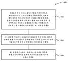
한 대표적인 양태에서, 개시된 기술은 비디오 처리를 위한 방법을 제공하는데 이용될 수 있다. 예시적인 방법은, 비디오의 루마 비디오 블록이 행렬 기반의 인트라 예측(MIP) 모드를 이용하여 코딩되어 있는지에 관한 제1 결정을 수행하는 단계 ― 이 모드에서, 루마 비디오 블록의 예측 블록은, 상기 비디오의 이전에 코딩된 샘플들에 관해, 경계 다운샘플링 동작, 후속하는 행렬 벡터 곱셈 동작, 및 선택적으로 후속하는 업샘플링 동작을 수행함으로써 결정됨 ―; 루마 비디오 블록이 비디오의 현재 크로마 비디오 블록에 대한 크로마 인트라 모드를 결정하는데 적용가능하다는 제2 결정을 수행하는 단계 ― 상기 제2 결정을 수행하는 단계는, 현재 크로마 비디오 블록과 연관된 현재 픽처의 상단 좌측 루마 샘플에 관한 현재 크로마 비디오 블록의 상단 좌측 샘플에 기초하고, 상기 제2 결정을 수행하는 단계는 현재 비디오 유닛의 루마 비디오 블록 및/또는 컬러 포맷에 관한 현재 크로마 비디오 블록의 치수들에 기초함 ―; 상기 제1 결정 및 상기 제2 결정에 기초하여, 상기 현재 크로마 비디오 블록에 이용될 상기 크로마 인트라 모드에 관한 제3 결정을 수행하는 단계; 및 상기 제3 결정에 기초하여, 상기 현재 크로마 비디오 블록과 상기 현재 크로마 비디오 블록의 비트스트림 표현 사이의 변환을 수행하는 단계를 포함한다.In one exemplary aspect, the disclosed technology may be used to provide a method for video processing. An exemplary method includes performing a first determination as to whether a luma video block of video is coded using a matrix-based intra prediction (MIP) mode, wherein the predictive block of a luma video block is the video determined by performing a boundary downsampling operation, a subsequent matrix vector multiply operation, and optionally a subsequent upsampling operation, on previously coded samples of ; performing a second determination that the luma video block is applicable to determine a chroma intra mode for a current chroma video block of video, wherein performing the second determination comprises: top left of a current picture associated with the current chroma video block based on a top left sample of the current chroma video block with respect to the luma sample, wherein performing the second determination is based on dimensions of the luma video block of the current video unit and/or the current chroma video block with respect to the color format; ; performing a third determination regarding the chroma intra mode to be used for the current chroma video block based on the first determination and the second determination; and performing conversion between the current chroma video block and a bitstream representation of the current chroma video block based on the third determination.
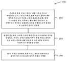
또 다른 대표적인 양태에서, 개시된 기술은 비디오 처리를 위한 방법을 제공하는데 이용될 수 있다. 예시적인 방법은, 비디오의 루마 비디오 블록이 행렬 기반의 인트라 예측(MIP) 모드를 이용하여 코딩되어 있다는 제1 결정을 수행하는 단계 ― 이 모드에서, 루마 비디오 블록의 예측 블록은, 상기 비디오의 이전에 코딩된 샘플들에 관해, 경계 다운샘플링 동작, 후속하는 행렬 벡터 곱셈 동작, 및 선택적으로 후속하는 업샘플링 동작을 수행함으로써 결정됨 ―; 상기 제1 결정에 기초하여, 도출된 모드(derived mode)(DM)가 상기 루마 비디오 블록과 연관된 현재 크로마 비디오 블록에 대한 크로마 인트라 모드로서 이용되는지에 관한 규칙에 따른 제2 결정을 수행하는 단계; 및 상기 제2 결정에 기초하여, 현재 크로마 비디오 블록과 상기 현재 크로마 비디오 블록의 비트스트림 표현 사이의 변환을 수행하는 단계를 포함한다.In another representative aspect, the disclosed technology may be used to provide a method for video processing. An exemplary method includes performing a first determination that a luma video block of video is coded using a matrix-based intra prediction (MIP) mode, in which a predictive block of a luma video block is a previous determined by performing a boundary downsampling operation, a subsequent matrix vector multiplication operation, and optionally a subsequent upsampling operation, on the samples coded in ; performing, based on the first determination, a second determination according to a rule regarding whether a derived mode (DM) is used as a chroma intra mode for a current chroma video block associated with the luma video block; and based on the second determination, performing a transform between a current chroma video block and a bitstream representation of the current chroma video block.
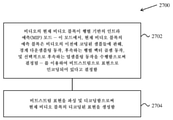
또 다른 대표적인 양태에서, 개시된 기술은 비디오 처리를 위한 방법을 제공하는데 이용될 수 있다. 예시적인 방법은, 비디오의 현재 비디오 블록이 행렬 기반의 인트라 예측(MIP) 모드로 코딩되어 있다고 결정하는 단계 ― 이 모드에서, 현재 비디오 블록의 예측 블록은, 상기 비디오의 이전에 코딩된 샘플들에 관해, 경계 다운샘플링 동작, 후속하는 행렬 벡터 곱셈 동작, 및 선택적으로 후속하는 업샘플링 동작을 수행함으로써 결정됨 ―; 상기 결정에 기초하여, 규칙에 기초한 최대 가능성 모드(most probable mode)(MPM) 목록을 생성하는 단계 ― 상기 규칙은 상기 MPM 목록이 상기 현재 비디오 블록의 이웃 비디오 블록에 대해 생성된 또 다른 MPM 목록과는 독립적으로 생성됨을 명시함 ―; 및 상기 MPM 목록을 이용하여 상기 현재 비디오 블록과 상기 현재 비디오 블록의 비트스트림 표현 사이의 변환을 수행하는 단계를 포함한다.In another representative aspect, the disclosed technology may be used to provide a method for video processing. An exemplary method includes determining that a current video block of video is coded in a matrix-based intra prediction (MIP) mode, in which the predictive block of the current video block corresponds to previously coded samples of the video. , determined by performing a boundary downsampling operation, a subsequent matrix vector multiply operation, and optionally a subsequent upsampling operation; generating, based on the determination, a rule-based most probable mode (MPM) list, wherein the MPM list includes another MPM list generated for a neighboring video block of the current video block and specifies that it is created independently ―; and performing conversion between the current video block and a bitstream representation of the current video block using the MPM list.
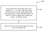
또 다른 대표적인 양태에서, 개시된 기술은 비디오 처리를 위한 방법을 제공하는데 이용될 수 있다. 예시적인 방법은, 비디오의 현재 비디오 블록을 행렬 기반의 인트라 예측 모드(matrix based intra prediction)(MIP) 모드를 이용하여 인코딩하는 단계 ― 이 모드에서, 현재 비디오 블록의 예측 블록은, 상기 비디오의 이전에 코딩된 샘플들에 관해, 경계 다운샘플링 동작, 후속하는 행렬 벡터 곱셈 동작, 및 선택적으로 후속하는 업샘플링 동작을 수행함으로써 결정되고, 규칙은 상기 MIP 모드에서 이용되는 행렬의 수와 상기 현재 비디오 블록의 치수들 사이의 관계를 기술함 ―; 상기 현재 비디오 블록의 인코딩된 표현을 상기 현재 비디오 블록의 비트스트림 표현에 추가하는 단계를 포함한다.In another representative aspect, the disclosed technology may be used to provide a method for video processing. An exemplary method includes encoding a current video block of video using a matrix based intra prediction (MIP) mode, wherein the predictive block of the current video block is a previous block of the video. is determined by performing a boundary downsampling operation, a subsequent matrix vector multiplication operation, and optionally a subsequent upsampling operation on the samples coded in , the rule is the number of matrices used in the MIP mode and the current video block describes the relationship between the dimensions of -; adding the encoded representation of the current video block to a bitstream representation of the current video block.
또 다른 대표적인 양태에서, 개시된 기술은 비디오 처리를 위한 방법을 제공하는데 이용될 수 있다. 예시적인 방법은, 비디오의 현재 비디오 블록이 행렬 기반의 인트라 예측(MIP) 모드를 이용하여 비트스트림 표현으로 인코딩되어 있다고 결정하는 단계 ― 이 모드에서, 현재 비디오 블록의 예측 블록은, 상기 비디오의 이전에 코딩된 샘플들에 관해, 경계 다운샘플링 동작, 후속하는 행렬 벡터 곱셈 동작, 및 선택적으로 후속하는 업샘플링 동작을 수행함으로써 결정되고, 규칙은 상기 MIP 모드에서 이용되는 행렬의 수와 상기 현재 비디오 블록의 치수들 사이의 관계를 기술함 ―; 및 상기 비트스트림 표현을 파싱 및 디코딩함으로써 상기 현재 비디오 블록의 디코딩된 표현을 생성하는 단계를 포함한다.In another representative aspect, the disclosed technology may be used to provide a method for video processing. An exemplary method includes determining that a current video block of video is encoded in a bitstream representation using a matrix-based intra prediction (MIP) mode, wherein the predictive block of the current video block is a previous block of the video. is determined by performing a boundary downsampling operation, a subsequent matrix vector multiplication operation, and optionally a subsequent upsampling operation on the samples coded in , the rule is the number of matrices used in the MIP mode and the current video block describes the relationship between the dimensions of -; and generating a decoded representation of the current video block by parsing and decoding the bitstream representation.
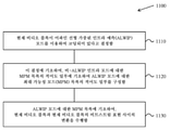
또 다른 대표적인 양태에서, 개시된 기술은 비디오 처리를 위한 방법을 제공하는데 이용될 수 있다. 이 예시적인 방법은, 현재 비디오 블록이 어파인 선형 가중된 인트라 예측(affine linear weighted intra prediction)(ALWIP) 모드를 이용하여 코딩되어 있다고 결정하는 단계; 상기 결정에 기초하여, 비ALWIP 인트라 모드에 대한 MPM 목록의 적어도 일부에 기초하여 ALWIP 모드에 대한 최고 가능성 모드(MPM) 목록의 적어도 일부를 구성하는 단계; 및 상기 ALWIP 모드에 대한 상기 MPM 목록에 기초하여, 상기 현재 비디오 블록과 상기 현재 비디오 블록의 비트스트림 표현 사이의 변환을 수행하는 단계를 포함한다.In another representative aspect, the disclosed technology may be used to provide a method for video processing. This example method includes determining that a current video block is coded using an affine linear weighted intra prediction (ALWIP) mode; based on the determination, configuring at least a portion of a highest likelihood mode (MPM) list for the ALWIP mode based on at least a portion of the MPM list for the non-ALWIP intra mode; and performing conversion between the current video block and a bitstream representation of the current video block based on the MPM list for the ALWIP mode.
또 다른 대표적인 양태에서, 개시된 기술은 비디오 처리를 위한 방법을 제공하는데 이용될 수 있다. 이 예시적인 방법은, 현재 비디오 블록의 루마 성분이 어파인 선형 가중된 인트라 예측(ALWIP) 모드를 이용하여 코딩되어 있다고 결정하는 단계; 상기 결정에 기초하여, 크로마 인트라 모드를 추론하는 단계, 상기 크로마 인트라 모드에 기초하여, 상기 현재 비디오 블록과 상기 현재 비디오 블록의 비트스트림 표현 사이의 변환을 수행하는 단계를 포함한다.In another representative aspect, the disclosed technology may be used to provide a method for video processing. This example method includes determining that a luma component of a current video block is coded using an affine linear weighted intra prediction (ALWIP) mode; based on the determination, inferring a chroma intra mode; and performing, based on the chroma intra mode, a transform between the current video block and a bitstream representation of the current video block.
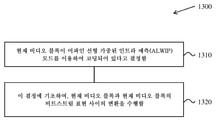
역시 또 다른 대표적인 양태에서, 개시된 기술은 비디오 처리를 위한 방법을 제공하는데 이용될 수 있다. 이 예시적인 방법은, 현재 비디오 블록이 어파인 선형 가중된 인트라 예측(ALWIP) 모드를 이용하여 코딩되어 있다고 결정하는 단계; 및 상기 결정에 기초하여, 상기 현재 비디오 블록과 상기 현재 비디오 블록의 비트스트림 표현 사이의 변환을 수행하는 단계를 포함한다.In yet another representative aspect, the disclosed technology may be used to provide a method for video processing. This example method includes determining that a current video block is coded using an affine linear weighted intra prediction (ALWIP) mode; and based on the determination, performing a transform between the current video block and a bitstream representation of the current video block.
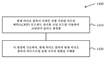
역시 또 다른 대표적인 양태에서, 개시된 기술은 비디오 처리를 위한 방법을 제공하는데 이용될 수 있다. 이 예시적인 방법은, 현재 비디오 블록이 어파인 선형 가중된 인트라 예측(ALWIP) 모드와는 상이한 코딩 모드를 이용하여 코딩되어 있다고 결정하는 단계, 및 상기 결정에 기초하여, 상기 현재 비디오 블록과 상기 현재 비디오 블록의 비트스트림 표현 사이의 변환을 수행하는 단계를 포함한다.In yet another representative aspect, the disclosed technology may be used to provide a method for video processing. This exemplary method includes determining that a current video block is coded using a coding mode different from an affine linear weighted intra prediction (ALWIP) mode, and based on the determination, the current video block and the current performing transformations between bitstream representations of video blocks.
역시 또 다른 대표적인 양태에서, 개시된 기술은 비디오 처리를 위한 방법을 제공하는데 이용될 수 있다. 이 예시적인 방법은, 현재 비디오 블록에 대해, 어파인 선형 가중된 인트라 예측(ALWIP) 모드를 이용하여 제1 예측을 생성하는 단계; 상기 제1 예측에 기초하여, 위치 의존 인트라 예측 조합(position dependent intra prediction combination)(PDPC)을 이용하여 제2 예측을 생성하는 단계; 및 상기 제2 예측에 기초하여, 상기 현재 비디오 블록과 상기 현재 비디오 블록의 비트스트림 표현 사이의 변환을 수행하는 단계를 포함한다.In yet another representative aspect, the disclosed technology may be used to provide a method for video processing. This example method includes generating, for a current video block, a first prediction using an affine linear weighted intra prediction (ALWIP) mode; based on the first prediction, generating a second prediction using a position dependent intra prediction combination (PDPC); and performing a transform between the current video block and a bitstream representation of the current video block based on the second prediction.
역시 또 다른 대표적인 양태에서, 개시된 기술은 비디오 처리를 위한 방법을 제공하는데 이용될 수 있다. 이 예시적인 방법은, 현재 비디오 블록이 어파인 선형 가중된 인트라 예측(ALWIP) 모드를 이용하여 코딩되어 있다고 결정하는 단계; ALWIP 모드에 기초하여, 상기 현재 비디오 블록의 복수의 서브블록을 예측하는 단계; 및 상기 예측에 기초하여, 상기 현재 비디오 블록과 상기 현재 비디오 블록의 비트스트림 표현 사이의 변환을 수행하는 단계를 포함한다.In yet another representative aspect, the disclosed technology may be used to provide a method for video processing. This example method includes determining that a current video block is coded using an affine linear weighted intra prediction (ALWIP) mode; predicting a plurality of subblocks of the current video block based on the ALWIP mode; and performing, based on the prediction, a transform between the current video block and a bitstream representation of the current video block.
역시 또 다른 대표적인 양태에서, 비디오 처리 방법이 개시된다. 이 방법은, 현재 비디오 블록에 대한 규칙에 기초하여, 현재 비디오 블록과 상기 현재 비디오 블록의 비트스트림 표현 사이의 변환 동안 어파인 선형 가중된 인트라 예측(ALWIP) 모드의 이용을 나타내는 플래그의 컨텍스트를 결정하는 단계; ALWIP 모드에 기초하여, 상기 현재 비디오 블록의 복수의 서브블록을 예측하는 단계; 및 상기 예측에 기초하여, 현재 비디오 블록과 현재 비디오 블록의 비트스트림 표현 사이의 변환을 수행하는 단계를 포함한다.In yet another representative aspect, a video processing method is disclosed. The method determines, based on a rule for a current video block, the context of a flag indicating use of an affine linear weighted intra prediction (ALWIP) mode during transformation between a current video block and a bitstream representation of the current video block. to do; predicting a plurality of subblocks of the current video block based on the ALWIP mode; and performing, based on the prediction, a transform between the current video block and a bitstream representation of the current video block.
역시 또 다른 대표적인 양태에서, 비디오 처리 방법이 개시된다. 방법은, 현재 비디오 블록이 어파인 선형 가중된 인트라 예측(ALWIP) 모드를 이용하여 코딩되어 있다고 결정하는 단계; 및 상기 현재 비디오 블록과 상기 현재 비디오 블록의 비트스트림 표현 사이의 변환 동안, 상기 ALWIP 모드와 연관된 업샘플링 프로세스에서 현재 비디오 블록의 샘플들에 관해 적어도 2개의 필터링 스테이지를 수행하는 단계를 포함하고, 상기 적어도 2개의 필터링 스테이지 중 제1 필터링 스테이지에서의 샘플들의 제1 정밀도는 상기 적어도 2개의 필터링 스테이지 중 제2 필터링 스테이지에서의 샘플들의 제2 정밀도와는 상이하다.In yet another representative aspect, a video processing method is disclosed. The method includes determining that a current video block is coded using an affine linear weighted intra prediction (ALWIP) mode; and during conversion between the current video block and a bitstream representation of the current video block, performing at least two filtering stages on samples of the current video block in an upsampling process associated with the ALWIP mode, wherein A first precision of the samples in a first of the at least two filtering stages is different from a second precision of the samples in a second of the at least two filtering stages.
역시 또 다른 양태에서, 비디오 처리 방법이 개시된다. 이 방법은, 현재 비디오 블록이 어파인 선형 가중된 인트라 예측(ALWIP) 모드를 이용하여 코딩되어 있다고 결정하는 단계; 및 상기 현재 비디오 블록과 상기 현재 비디오 블록의 비트스트림 표현 사이의 변환 동안, 상기 ALWIP 모드와 연관된 업샘플링 프로세스에서 현재 비디오 블록의 샘플들에 관해 적어도 2개의 필터링 스테이지를 수행하는 단계를 포함하고, 상기 업샘플링 프로세스는, 수직 및 수평 업샘플링 양쪽 모두가 수행되는 경우 고정된 순서로 수행된다.In yet another aspect, a video processing method is disclosed. The method includes determining that a current video block is coded using an affine linear weighted intra prediction (ALWIP) mode; and during conversion between the current video block and a bitstream representation of the current video block, performing at least two filtering stages on samples of the current video block in an upsampling process associated with the ALWIP mode, wherein The upsampling process is performed in a fixed order when both vertical and horizontal upsampling are performed.
역시 또 다른 양태에서, 비디오 처리 방법이 개시된다. 이 방법은, 현재 비디오 블록이 어파인 선형 가중된 인트라 예측(ALWIP) 모드를 이용하여 코딩되어 있다고 결정하는 단계; 및 상기 현재 비디오 블록과 상기 현재 비디오 블록의 비트스트림 표현 사이의 변환 동안, 상기 ALWIP 모드와 연관된 업샘플링 프로세스에서 현재 비디오 블록의 샘플들에 관해 적어도 2개의 필터링 스테이지를 수행하는 단계를 포함하고, 상기 변환은 상기 업샘플링 프로세스 이전에 전치 동작(transposing operation)을 수행하는 단계를 포함한다.In yet another aspect, a video processing method is disclosed. The method includes determining that a current video block is coded using an affine linear weighted intra prediction (ALWIP) mode; and during conversion between the current video block and a bitstream representation of the current video block, performing at least two filtering stages on samples of the current video block in an upsampling process associated with the ALWIP mode, wherein Transformation includes performing a transposing operation prior to the upsampling process.
역시 또 다른 대표적인 양태에서, 전술된 방법은 프로세서-실행가능한 코드의 형태로 구현되어 컴퓨터-판독가능 프로그램 매체에 저장된다.In yet another representative aspect, the method described above is embodied in the form of processor-executable code and stored on a computer-readable program medium.
역시 또 다른 대표적인 양태에서, 전술된 방법을 수행하도록 구성되거나 동작가능한 디바이스가 개시된다. 디바이스는, 이 방법을 구현하도록 프로그래밍된 프로세서를 포함할 수 있다.In yet another representative aspect, a device configured or operable to perform the method described above is disclosed. The device may include a processor programmed to implement the method.
역시 또 다른 대표적인 양태에서, 비디오 디코더 장치는 여기서 설명된 방법을 구현할 수 있다.In yet another representative aspect, a video decoder apparatus may implement the methods described herein.
개시된 기술의 상기 및 기타의 양태들 및 피처들은, 도면들, 상세한 설명 및 청구항들에서 더 상세하게 설명된다.These and other aspects and features of the disclosed technology are set forth in greater detail in the drawings, the description and the claims.
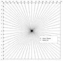
도 1은 33개의 인트라 예측 방향의 한 예를 도시한다.
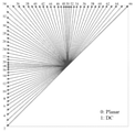
도 2는 67개의 인트라 예측 모드의 한 예를 나타낸다.
도 3은 선형 모델의 가중치들의 도출에 이용된 샘플들의 위치들의 한 예를 도시한다.
도 4는 예측 블록에 이웃한 4개의 기준 라인의 한 예를 도시한다.
도 5a 및 도 5b는 블록 크기에 따른 서브파티션들의 예들을 도시한다.
도 6은 4×4 블록들에 대한 ALWIP의 한 예를 도시한다.
도 7은 8×8 블록들에 대한 ALWIP의 한 예를 도시한다.
도 8은 8×4 블록들에 대한 ALWIP의 한 예를 도시한다.
도 9는 16×16 블록들에 대한 ALWIP의 한 예를 도시한다.
도 10은 MPM 목록 구성에서 이용하는 이웃 블록들의 한 예를 도시한다.
도 11은 개시된 기술에 따른 행렬 기반의 인트라 예측을 위한 한 예시적인 방법의 플로차트를 도시한다.
도 12는 개시된 기술에 따른 행렬 기반의 인트라 예측을 위한 또 다른 예시적인 방법의 플로차트를 도시한다.
도 13은 개시된 기술에 따른 행렬 기반의 인트라 예측을 위한 역시 또 다른 예시적인 방법의 플로차트를 도시한다.
도 14는 개시된 기술에 따른 행렬 기반의 인트라 예측을 위한 역시 또 다른 예시적인 방법의 플로차트를 도시한다.
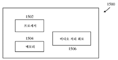
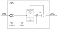
도 15는 본 문서에 설명된 시각적 미디어 디코딩 또는 시각적 미디어 인코딩 기술을 구현하기 위한 하드웨어 플랫폼의 한 예의 블록도이다.
도 16은 이웃 블록들의 한 예를 도시한다.
도 17은 제안된 감축된 경계 샘플들 생성의 한 예이다.
도 18은 원래의 복원된 이웃 샘플들을 이용한 제안된 업샘플링의 한 예를 도시한다.
도 19는 비디오 디코더의 한 예를 나타내는 블록도이다.
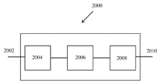
도 20은 여기서 개시된 다양한 기술이 구현될 수 있는 한 예시적인 비디오 처리 시스템을 도시하는 블록도이다.
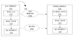
도 21은 본 개시내용의 기술들을 이용할 수 있는 한 예시적인 비디오 코딩 시스템을 나타내는 블록도이다.
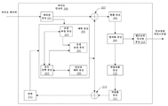
도 22는 비디오 인코더의 한 예를 나타내는 블록도이다.
도 23 내지 도 27은 개시된 기술에 따른 행렬 기반의 인트라 예측을 위한 추가적인 예시적인 방법들의 플로차트를 도시한다.1 shows an example of 33 intra prediction directions.
2 shows an example of 67 intra prediction modes.
3 shows an example of the positions of samples used for derivation of weights of a linear model.
4 shows an example of four reference lines adjacent to a prediction block.
5A and 5B show examples of sub-partitions according to block size.
6 shows an example of ALWIP for 4x4 blocks.
7 shows an example of ALWIP for 8x8 blocks.
8 shows an example of ALWIP for 8x4 blocks.
9 shows an example of ALWIP for 16×16 blocks.
10 shows an example of neighboring blocks used in MPM list construction.
11 shows a flowchart of an exemplary method for matrix-based intra prediction in accordance with the disclosed technology.
12 shows a flowchart of another exemplary method for matrix-based intra prediction in accordance with the disclosed technology.
13 shows a flowchart of yet another exemplary method for matrix-based intra prediction in accordance with the disclosed technology.
14 shows a flowchart of yet another exemplary method for matrix-based intra prediction in accordance with the disclosed technology.
15 is a block diagram of an example of a hardware platform for implementing the visual media decoding or visual media encoding techniques described herein.
16 shows an example of neighboring blocks.
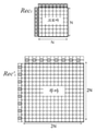
17 is an example of the proposed generation of reduced boundary samples.
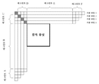
18 shows an example of the proposed upsampling using original reconstructed neighboring samples.
19 is a block diagram illustrating an example of a video decoder.
20 is a block diagram illustrating an example video processing system in which the various techniques disclosed herein may be implemented.
21 is a block diagram illustrating an example video coding system that may utilize the techniques of this disclosure.
22 is a block diagram illustrating an example of a video encoder.
23-27 show flowcharts of additional example methods for matrix-based intra prediction in accordance with the disclosed technology.
고해상도 비디오에 대한 수요가 증가함에 따라, 비디오 코딩 방법들 및 기술들은 현대 기술에서 유비쿼터스이다. 비디오 코덱은 전형적으로 디지털 비디오를 압축하거나 압축해제하는 전자 회로 또는 소프트웨어를 포함하고, 더 높은 코딩 효율성을 제공하기 위해 지속적으로 개선되고 있다. 비디오 코덱은 압축되지 않은 비디오를 압축된 포맷으로 또는 그 반대로 변환한다. 비디오 품질, (비트 레이트에 의해 결정되는) 비디오를 나타내는데 이용되는 데이터의 양, 인코딩 및 디코딩 알고리즘들의 복잡성, 데이터 손실들 및 오류들에 대한 민감도, 편집 용이성, 랜덤 액세스, 및 종단간 지연(레이턴시) 사이에는 복잡한 관계들이 존재한다. 압축된 포맷은 대개, 표준 비디오 압축 명세, 예를 들어 HEVC(High Efficiency Video Coding) 표준(H.265 또는 MPEG-H Part 2라고도 알려짐), 마무리 예정인 VVC(Versatile Video Coding) 표준, 또는 기타의 현재 및/또는 미래의 비디오 코딩 표준들을 준수한다.As the demand for high resolution video increases, video coding methods and techniques are ubiquitous in modern technology. Video codecs typically include electronic circuitry or software to compress or decompress digital video, and are constantly being improved to provide higher coding efficiency. A video codec converts uncompressed video to a compressed format and vice versa. Video quality, amount of data used to represent video (as determined by bit rate), complexity of encoding and decoding algorithms, sensitivity to data losses and errors, ease of editing, random access, and end-to-end delay (latency) There are complex relationships between them. Compressed formats are usually based on standard video compression specifications, such as the High Efficiency Video Coding (HEVC) standard (also known as H.265 or MPEG-H Part 2), the upcoming Versatile Video Coding (VVC) standard, or other current and/or comply with future video coding standards.
개시된 기술의 실시예들은 런타임 성능을 개선하기 위해 기존의 비디오 코딩 표준들(예를 들어, HEVC, H.265) 및 미래의 표준들에 적용될 수 있다. 섹션 제목들은 본 문서에서 설명의 가독성을 향상시키기 위해 이용되며 논의 또는 실시예들(및/또는 구현들)을 각각의 섹션들로만 어떤 식으로든 제한하지 않는다.Embodiments of the disclosed technology may be applied to existing video coding standards (eg, HEVC, H.265) and future standards to improve runtime performance. Section headings are used to improve the readability of the description herein and do not in any way limit the discussion or embodiments (and/or implementations) to only their respective sections.
1 HEVC에 대한 간략한 검토1 A Brief Review of HEVC
1.1 HEVC/H.265에서의 인트라 예측1.1 Intra prediction in HEVC/H.265
인트라 예측은, 고려된 컬러 채널에서 이전에 복원된 샘플들을 이용하여 주어진 TB(transform block; 변환 블록)에 대한 샘플들을 생성하는 것을 포함한다. 인트라 예측 모드는 루마 및 크로마 채널들에 대해 별개로 시그널링되며, 크로마 채널 인트라 예측 모드는 'DM_CHROMA' 모드를 통해 루마 채널 인트라 예측 모드에 선택적으로 의존한다. 인트라 예측 모드는 PB(prediction block; 예측 블록) 레벨에서 시그널링되지만, CU에 대한 잔차 쿼드 트리 계층구조에 따라 TB 레벨에서 인트라 예측 프로세스가 적용됨으로써, 1개 TB의 코딩이 CU 내의 다음 TB의 코딩에 영향을 미치는 것을 허용하므로, 기준 값들로서 이용되는 샘플까지의 거리를 감축시킨다.Intra prediction involves generating samples for a given transform block (TB) using previously reconstructed samples in a considered color channel. The intra prediction mode is signaled separately for the luma and chroma channels, and the chroma channel intra prediction mode selectively depends on the luma channel intra prediction mode via the 'DM_CHROMA' mode. The intra prediction mode is signaled at the prediction block (PB) level, but the intra prediction process is applied at the TB level according to the residual quad tree hierarchy for the CU, so that the coding of one TB is the coding of the next TB within the CU. reducing the distance to the sample which is used as reference values, as it allows for influencing.
HEVC는, 35개의 인트라 예측 모드 ― DC 모드, 평면 모드 및 33개의 방향성, 또는 '각도' 인트라 예측 모드를 포함한다. 33개의 각도 인트라 예측 모드가 도 1에 나와 있다.HEVC includes 35 intra prediction modes—DC mode, planar mode and 33 directional, or 'angular' intra prediction modes. 33 angular intra prediction modes are shown in FIG. 1 .
크로마 컬러 채널과 연관된 PB들의 경우, 인트라 예측 모드는, 평면, DC, 수평, 수직, 'DM_CHROMA' 모드 또는 때로는 대각선 모드 '34'로서 명시된다.For PBs associated with a chroma color channel, the intra prediction mode is specified as planar, DC, horizontal, vertical, 'DM_CHROMA' mode or sometimes diagonal mode '34'.
크로마 포맷들 4:2:2 및 4:2:0의 경우, 크로마 PB는 2개 또는 4개의 (각각) 루마 PB와 중첩될 수 있다; 이 경우 DM_CHROMA에 대한 루마 방향은 이들 루마 PB들의 상단 좌측에서 취해진다는 점에 유의한다.For chroma formats 4:2:2 and 4:2:0, a chroma PB may overlap with two or four (respectively) luma PBs; Note that in this case the luma direction for DM_CHROMA is taken from the top left of these luma PBs.
DM_CHROMA 모드는, 루마 컬러 채널 PB의 인트라 예측 모드가 크로마 컬러 채널 PB들에 적용됨을 나타낸다. 이것은 비교적 일반적이기 때문에, intra_chroma_pred_mode의 최고-가능성-모드 코딩 방식은 이 모드가 선택되도록 편향된다.DM_CHROMA mode indicates that the intra prediction mode of the luma color channel PB is applied to the chroma color channel PBs. Since this is relatively common, the highest-probability-mode coding scheme of intra_chroma_pred_mode is biased such that this mode is selected.
2. VVC에서 인트라 예측의 예들2. Examples of intra prediction in VVC
2.1 67개의 인트라 예측 모드를 이용한 인트라 모드 코딩2.1 Intra mode coding using 67 intra prediction modes
자연스런 비디오에서 나타나는 임의의 엣지 방향들을 캡처하기 위해, 방향성 인트라 모드의 수는, HEVC에서 이용될 때, 33에서 65로 확장된다. 추가적인 방향 모드들은 도 2에서 빨간색 점선 화살표들로 표시되며, 평면 및 DC 모드는 동일하게 유지된다. 이들 더 조밀한 방향성 인트라 예측 모드들은, 모든 블록 크기에 대해, 및 루마 및 크로마 인트라 예측 양쪽 모두에 대해 적용된다.To capture any edge directions that appear in natural video, the number of directional intra modes, when used in HEVC, is extended from 33 to 65. Additional directional modes are indicated by the red dotted arrows in FIG. 2 , the planar and DC modes remain the same. These denser directional intra prediction modes apply for all block sizes and for both luma and chroma intra prediction.
2.2 교차-성분 선형 모델(CCLM)의 예들2.2 Examples of Cross-Component Linear Models (CCLMs)
일부 실시예에서, 및 교차-성분 중복성을 감축시키기 위해, 다음과 같이 선형 모델을 이용함으로써 동일한 CU의 복원된 루마 샘플들에 기초하여 크로마 샘플들이 예측되는 JEM에서 교차-성분 선형 모델(CCLM) 예측 모드(LM이라고도 함)가 이용된다:In some embodiments, and to reduce cross-component redundancy, cross-component linear model (CCLM) prediction in JEM where chroma samples are predicted based on reconstructed luma samples of the same CU by using a linear model as follows A mode (also called LM) is used:
![]()
![]()
여기서, ![]()
![]()
![]()
![]()
![]()
![]()
![]()
![]()
이 파라미터 계산은 디코딩 프로세스의 일부로 수행되고, 인코더 검색 동작과 같지 않다. 그 결과, ![]()
![]()
![]()
![]()
크로마 인트라 모드 코딩의 경우, 크로마 인트라 모드 코딩을 위해 총 8개의 인트라 모드가 허용된다. 이들 모드는, 5개의 전통적인 인트라 모드와 3개의 교차-성분 선형 모델 모드(CCLM, LM_A 및 LM_L)를 포함한다. 크로마 모드 코딩은 대응하는 루마 블록의 인트라 예측 모드에 직접적으로 의존한다. I개 슬라이스에서 루마 및 크로마 성분들에 대한 별개의 블록 분할 구조가 인에이블되기 때문에, 하나의 크로마 블록은 복수의 루마 블록에 대응할 수 있다. 따라서, 크로마 DM 모드의 경우, 현재 크로마 블록의 중심 위치를 커버하는 대응하는 루마 블록의 인트라 예측 모드가 직접 상속된다.In the case of chroma intra mode coding, a total of eight intra modes are allowed for chroma intra mode coding. These modes include five traditional intra modes and three cross-component linear model modes (CCLM, LM_A and LM_L). Chroma mode coding directly depends on the intra prediction mode of the corresponding luma block. Since a separate block division structure for luma and chroma components is enabled in I slices, one chroma block may correspond to a plurality of luma blocks. Accordingly, in the case of the chroma DM mode, the intra prediction mode of the corresponding luma block covering the center position of the current chroma block is directly inherited.
2.3 복수의 기준 라인(MRL) 인트라 예측2.3 Multiple Reference Lines (MRL) Intra Prediction
복수의 기준 라인(MRL) 인트라 예측은 인트라 예측을 위해 더 많은 기준 라인을 이용한다. 도 4에서, 4개의 기준 라인의 예가 나와 있고, 여기서, 세그먼트 A 및 F의 샘플들은 복원된 이웃 샘플들로부터 가져온 것이 아니라, 세그먼트 B 및 E로부터 가장 가까운 샘플들로 각각 패딩된다. HEVC 인트라-픽처 예측은 가장 가까운 기준 라인(즉, 기준 라인 0)을 이용한다. MRL에서, 2개의 추가적인 라인(기준 라인 1 및 기준 라인 3)이 이용된다. 선택된 기준 라인의 인덱스(mrl_idx)는 시그널링되고 인트라 예측자를 생성하는데 이용된다. 0보다 큰 기준 라인 idx의 경우, MPM 목록에는 추가적인 기준 라인 모드들만 포함하고 나머지 모드 없이 신호 mpm 인덱스만 포함한다.Multiple reference lines (MRL) intra prediction uses more reference lines for intra prediction. In Figure 4, an example of four reference lines is shown, where the samples of segments A and F are padded with the closest samples from segments B and E, respectively, rather than from reconstructed neighboring samples. HEVC intra-picture prediction uses the nearest reference line (ie, reference line 0). In MRL, two additional lines (reference line 1 and reference line 3) are used. The index (mrl_idx) of the selected reference line is signaled and used to generate an intra predictor. For a reference line idx greater than zero, the MPM list contains only the additional reference line modes and only the signal mpm index without the remaining modes.
2.4 인트라 서브파티션들(ISP)2.4 Intra Subpartitions (ISP)
ISP(Intra Sub-Partitions) 툴은 루마 인트라 예측된 블록들을 블록 크기에 따라 수직 또는 수평으로 2개 또는 4개의 서브파티션으로 분할한다. 예를 들어, ISP에 대한 최소 블록 크기는 4x8(또는 8x4)이다. 블록 크기가 4x8(또는 8x4)보다 크다면, 대응하는 블록은 4개의 서브파티션으로 분할된다. 도 5는 2개의 가능성의 예들을 도시한다. 모든 서브파티션은 적어도 16개의 샘플을 갖는 조건을 충족한다.The Intra Sub-Partitions (ISP) tool divides the luma intra-predicted blocks into two or four sub-partitions either vertically or horizontally according to the block size. For example, the minimum block size for an ISP is 4x8 (or 8x4). If the block size is greater than 4x8 (or 8x4), the corresponding block is divided into 4 sub-partitions. 5 shows examples of two possibilities. All subpartitions meet the condition of having at least 16 samples.
각각의 서브파티션에 대해, 예측 신호에 잔차 신호를 추가함으로써 복원된 샘플이 획득된다. 여기서, 엔트로피 디코딩, 역양자화, 역변환 등의 프로세스들에 의해 잔차 신호가 생성된다. 따라서, 각각의 서브파티션의 복원된 샘플 값들은 다음 서브파티션의 예측을 생성하는데 이용가능하고, 각각의 서브파티션은 반복적으로 처리된다. 또한 처리될 첫 번째 서브파티션은 CU의 상단 좌측 샘플을 포함하고 계속해서 아래쪽(수평 분할) 또는 우측(수직 분할)으로 이어지는 서브파티션이다. 그 결과, 서브파티션 예측 신호들을 생성하는데 이용되는 기준 샘플들은 라인들의 좌측과 위쪽들에만 위치한다. 모든 서브파티션은 동일한 인트라 모드를 공유한다.For each subpartition, a reconstructed sample is obtained by adding a residual signal to the prediction signal. Here, a residual signal is generated by processes such as entropy decoding, inverse quantization, and inverse transform. Thus, the reconstructed sample values of each subpartition are available to generate a prediction of the next subpartition, and each subpartition is iteratively processed. Also, the first sub-partition to be processed is the sub-partition containing the top left sample of the CU and continuing to the bottom (horizontal partition) or right (vertical partition). As a result, the reference samples used to generate the subpartition prediction signals are located only on the left and above the lines. All subpartitions share the same intra mode.
2.5 어파인 선형 가중된 인트라 예측(ALWIP 또는 행렬 기반의 인트라 예측)2.5 Affine Linear Weighted Intra Prediction (ALWIP or Matrix-Based Intra Prediction)
어파인 선형 가중된 인트라 예측(ALWIP, 일명, 행렬 기반의 인트라 예측(MIP))은 JVET-N0217에서 제안된다.Affine linear weighted intra prediction (ALWIP, aka matrix-based intra prediction (MIP)) is proposed in JVET-N0217.
JVET-N0217에서, 2개의 테스트가 수행된다. 테스트 1에서, ALWIP는 8K 바이트의 메모리 제한과 샘플당 최대 4개의 곱셈으로 설계된다. 테스트 2는 테스트 1과 유사하지만, 메모리 요건 및 모델 아키텍처 측면에서 설계를 더욱 단순화한다.In JVET-N0217, two tests are performed. In Test 1, ALWIP is designed with a memory limit of 8K bytes and up to 4 multiplications per sample. Test 2 is similar to Test 1, but further simplifies the design in terms of memory requirements and model architecture.
○ 모든 블록 형상에 대한 단일 세트의 행렬들 및 오프셋 벡터들. ○ A single set of matrices and offset vectors for all block shapes.
○ 모든 블록 형상에 대한 19개로의 모드 수 감축. ○ Reduced number of modes to 19 for all block geometries.
○ 5760 10비트 값들, 즉, 7.20 킬로바이트로의 메모리 요건의 감축. ○ Reduction of memory requirement to 5760 10-bit values, ie 7.20 kilobytes.
○ 예측된 샘플들의 선형 보간은 첫 번째 테스트에서와 같이 반복 보간을 대체하여 방향당 단일의 단계에서 실행된다. ○ Linear interpolation of predicted samples is performed in a single step per direction, replacing iterative interpolation as in the first test.
2.5.1 JVET-N0217의 테스트 12.5.1 Test 1 of JVET-N0217
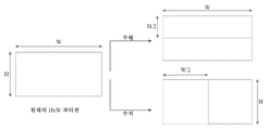
폭 ![]()
![]()
![]()
![]()
![]()
![]()
예측 신호의 생성은 다음과 같은 3개 단계에 기초한다:The generation of the prediction signal is based on three steps:
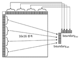
경계 샘플들 중에서, ![]()
![]()
오프셋의 추가가 뒤따르는 행렬 벡터 곱셈은 평균된 샘플들을 입력으로서 이용하여 실행된다. 결과는 원래 블록의 서브샘플링된 샘플 세트에 관한 감축된 예측 신호이다.Matrix vector multiplication followed by addition of an offset is performed using the averaged samples as input. The result is a reduced prediction signal for the subsampled set of samples of the original block.
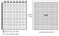
나머지 위치들에서의 예측 신호는, 각각의 방향에서의 단일 단계 선형 보간인 선형 보간에 의해 서브샘플링된 세트에 관한 예측 신호로부터 생성된다.The prediction signal at the remaining positions is generated from the prediction signal for the subsampled set by linear interpolation, which is a single-step linear interpolation in each direction.
예측 신호를 생성하는데 필요한 행렬들 및 오프셋 벡터들은 행렬들의 3개 세트 ![]()
![]()
![]()
![]()
![]()
![]()
![]()
![]()
![]()
![]()
![]()
![]()
![]()
![]()
![]()
![]()
![]()
![]()
![]()
![]()
![]()
![]()
행렬 벡터 곱의 계산에 요구되는 곱셈의 총 수는 항상 ![]()
![]()
2.5.2 경계의 평균화2.5.2 Boundary Averaging
제1 단계에서 입력 경계들 ![]()
![]()
![]()
![]()
![]()
![]()
![]()
![]()
![]()
![]()
![]()
![]()
4×4 블록의 경우, ![]()
![]()

그리고, 유사하게 ![]()
![]()
그렇지 않고, 블록 폭 W가 ![]()
![]()
![]()
![]()

그리고, 유사하게 ![]()
![]()
2개의 감축된 경계 ![]()
![]()
![]()
![]()
![]()
![]()
![]()
![]()

마지막으로, 서브샘플링된 예측 신호의 보간을 위해, 큰 블록들에서, 평균된 경계의 제2 버전이 필요하다. 즉, ![]()
![]()
![]()
![]()
![]()
![]()
![]()
![]()

![]()
![]()
![]()
![]()
![]()
![]()
2.5.3 행렬 벡터 곱셈에 의한 감축된 예측 신호의 생성2.5.3 Generation of Reduced Prediction Signals by Matrix Vector Multiplication
감축된 입력 벡터 ![]()
![]()
![]()
![]()
![]()
![]()
![]()
![]()
![]()
![]()
![]()
![]()

감축된 예측 신호 ![]()
![]()
![]()
![]()
![]()
![]()
![]()
![]()
![]()
![]()
![]()
![]()
![]()
![]()
행렬 ![]()
![]()
![]()
![]()
![]()
![]()
![]()
![]()

![]()
![]()

그 다음, ![]()
![]()
![]()
![]()
![]()
![]()
![]()
![]()
![]()
![]()
![]()
![]()
![]()
![]()
![]()
![]()
![]()
![]()
![]()
![]()
![]()
![]()
마지막으로, 감축된 예측 신호는 다음과 같은 경우들에서 그 전치(transpose)로 대체된다:Finally, the reduced prediction signal is replaced by its transpose in the following cases:

![]()
![]()
![]()
![]()
![]()
![]()
![]()
![]()
![]()
![]()
![]()
![]()
![]()
![]()
2.5.4 전체 ALWIP 프로세스의 예시2.5.4 Example of the entire ALWIP process
평균화, 행렬 벡터 곱셈 및 선형 보간의 전체 프로세스가 도 6 내지 도 9에서 상이한 형상들에 대해 예시되어 있다. 나머지 형상들은 도시된 경우들 중 하나인 것으로 취급된다는 점에 유의한다.The whole process of averaging, matrix vector multiplication and linear interpolation is illustrated for the different shapes in FIGS. 6 to 9 . Note that the remaining shapes are treated as being one of the illustrated cases.
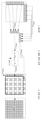
1. 4×4 블록이 주어지면, ALWIP는 경계의 각각의 축을 따라 2개의 평균을 취한다. 결과적인 4개의 입력 샘플은 행렬 벡터 곱셈에 들어간다. 행렬들은 세트 ![]()
![]()
![]()
![]()
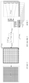
2. 8×8 블록이 주어지면, ALWIP는 경계의 각각의 축을 따라 4개의 평균을 취한다. 결과적인 8개의 입력 샘플은 행렬 벡터 곱셈에 들어간다. 행렬들은 세트 ![]()
![]()
![]()
![]()
3. 8×4 블록이 주어지면, ALWIP는 경계의 수평 축을 따라 4개의 평균 및 좌측 경계에서 4개의 원래 경계 값을 취한다. 결과적인 8개의 입력 샘플은 행렬 벡터 곱셈에 들어간다. 행렬들은 세트 ![]()
![]()
![]()
![]()
4. 16×16 블록이 주어지면, ALWIP는 경계의 각각의 축을 따라 4개의 평균을 취한다. 결과적인 8개의 입력 샘플은 행렬 벡터 곱셈에 들어간다. 행렬들은 세트 ![]()
![]()
![]()
![]()
더 큰 형상들의 경우, 절차는 본질적으로 동일하며 샘플당 곱셈 수가 4개보다 작은지를 체크하는 것이 쉽다.For larger shapes, the procedure is essentially the same and it is easy to check if the number of multiplications per sample is less than four.
W>8인 W×8 블록들의 경우, 샘플들이 홀수 수평 및 각각의 수직 위치들에 제공되므로 수평 보간만이 필요하다.For Wx8 blocks where W>8, only horizontal interpolation is required since samples are provided at odd horizontal and respective vertical positions.
마지막으로, W>8인 W×4 블록들의 경우, A_kbe를, 다운샘플링된 블록의 수평 축을 따라 홀수 엔트리에 대응하는 모든 행을 생략함으로써 발생하는 행렬이라고 하자. 따라서, 출력 크기는 32이고 다시 수평 보간만 수행된다.Finally, for Wx4 blocks where W>8, let A_kbe be the matrix resulting from omitting all rows corresponding to odd entries along the horizontal axis of the downsampled block. Therefore, the output size is 32 and again only horizontal interpolation is performed.
전치된 사례들은 그에 따라 취급된다.Transposed cases are treated accordingly.
2.5.5 단일 단계 선형 보간2.5.5 Single-step linear interpolation
![]()
![]()
![]()
![]()
![]()
![]()
![]()
![]()
![]()
![]()
일반성을 잃지 않고 ![]()
![]()
![]()
![]()
![]()
![]()
![]()
![]()
![]()
![]()

그 다음, 이 확장된 감축된 예측 신호로부터, 수직 선형 보간된 예측 신호는 다음과 같이 생성된다Then, from this extended reduced prediction signal, a vertically linear interpolated prediction signal is generated as
![]()
![]()
![]()
![]()
![]()
![]()
![]()
![]()
![]()
![]()
2.5.6 제안된 인트라 예측 모드들의 신호화2.5.6 Signaling of the proposed intra prediction modes
인트라 모드의 각각의 CU(Coding Unit)에 대해, ALWIP 모드가 대응하는 PU(Prediction Unit)에 적용될지의 여부를 나타내는 플래그가 비트스트림에서 전송된다. 후자 인덱스의 신호화는 JVET-M0043에서와 동일한 방식으로 MRL과 조율된다. ALWIP 모드가 적용되는 경우, ALWIP 모드의 인덱스 ![]()
![]()
여기서, MPM들의 도출은 위쪽과 좌측 PU의 인트라 모드들을 이용하여 다음과 같이 수행된다. 각각의 종래의 인트라 예측 모드 ![]()
![]()
![]()
![]()
![]()
![]()
![]()
![]()
![]()
폭 ![]()
![]()
![]()
![]()
![]()
![]()
이 인덱스는 섹션 2.5.3에서와 같이 ALWIP 파라미터들이 3개 세트 중 어느 것으로부터 선택되는지를 나타낸다.This index indicates from which of the three sets the ALWIP parameters are selected as in section 2.5.3.
위쪽 예측 유닛 ![]()
![]()
![]()
![]()
![]()
![]()
![]()
![]()
![]()
![]()
위쪽 PU가 이용가능하고 현재 PU와 동일한 CTU에 속하며, 인트라 모드에 있고 종래의 인트라 예측 모드 ![]()
![]()
![]()
![]()
다른 모든 경우에는, 다음과 같이 둘 수 있다In all other cases, you can put
![]()
![]()
이것은 이 모드가 이용가능하지 않음을 의미한다. 동일한 방식으로 그러나 좌측 PU가 현재 PU와 동일한 CTU에 속할 필요가 있다는 제한없이, 모드 ![]()
![]()
마지막으로, 3개의 고정된 디폴트 목록 ![]()
![]()
![]()
![]()
![]()
![]()
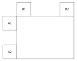
![]()
![]()
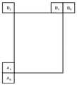
ALWIP MPM 목록 구성에 이용되는 좌측 이웃 블록 및 위쪽 이웃 블록은, 도 10에 도시된 바와 같이, A1과 B1이다.As shown in FIG. 10 , the left neighboring block and the upper neighboring block used in the ALWIP MPM list configuration are A1 and B1.
2.5.7 종래의 2.5.7 Conventional 루마luma 및 and 크로마chroma 인트라intra 예측 prediction 모드들에in the mods 대한 적응형 adaptive for MPMMPM 목록 도출 list derivation
제안된 ALWIP 모드들은 다음과 같이 종래의 인트라 예측 모드들 MPM 기반의 코딩과 조율된다. 종래의 인트라 예측 모드들에 대한 루마 및 크로마 MPM 목록 도출 프로세스들은, 고정 테이블들 ![]()
![]()
![]()
![]()
![]()
![]()
![]()
![]()
루마 MPM 목록 도출의 경우, ALWIP 모드 ![]()
![]()
![]()
![]()
2.5.8 대응하는 수정된 연구 초안2.5.8 Corresponding Revised Draft Study
일부 실시예에서, 이 섹션에서 설명된 바와 같이, intra_lwip_flag, intra_lwip_mpm_flag, intra_lwip_mpm_idx 및 intra_lwip_mpm_remainder와 관련된 부분들이 개시된 기술의 실시예들에 기초하여 연구 초안에 추가되었다.In some embodiments, as described in this section, parts related to intra_lwip_flag, intra_lwip_mpm_flag, intra_lwip_mpm_idx and intra_lwip_mpm_remainder were added to the draft study based on embodiments of the disclosed technology.
일부 실시예에서, 이 섹션에서 설명된 바와 같이, <begin> 및 <end> 태그들은 개시된 기술의 실시예들에 기초한 연구 초안에 대한 추가 및 수정을 나타내는데 이용된다.In some embodiments, as described in this section, the <begin> and <end> tags are used to indicate additions and modifications to the draft study based on embodiments of the disclosed technology.
신택스 테이블들syntax tables
코딩 유닛 신택스Coding Unit Syntax


시맨틱스semantics
<begin> intra _ lwip _flag[ x0 ][ y0 ]가 1인 것은, 루마 샘플에 대한 인트라 예측 유형이 어파인 선형 가중된 인트라 예측임을 명시한다. intra_lwip_flag[ x0 ][ y0 ]가 0인 것은, 루마 샘플들에 대한 인트라 예측 유형이 어파인 선형 가중된 인트라 예측이 아님을 명시한다. <begin> intra_lwip_flag [x0 ] [y0] equal to 1 specifies that the intra prediction type for the luma sample is an affine linear weighted intra prediction. intra_lwip_flag[ x0 ][ y0 ] equal to 0 specifies that the intra prediction type for luma samples is not an affine linear weighted intra prediction.
intra_lwip_flag[ x0 ][ y0 ]가 없는 것은, 0인 것으로 추론된다.The absence of intra_lwip_flag[ x0 ][ y0 ] is inferred to be zero.
신택스 요소들 intra_lwip_mpm_flag[ x0 ][ y0 ], intra_lwip_mpm_idx[ x0 ][ y0 ] 및 intra_lwip_mpm_remainder [ x0 ][ y0 ]는 루마 샘플들에 대한 어파인 선형 가중된 인트라 예측 모드를 명시한다. 어레이 인덱스들 x0, y0은, 픽처의 상단 좌측 루마 샘플에 관한 고려되는 코딩 블록의 상단 좌측 루마 샘플의 위치 (x0, y0)를 명시한다. intra_lwip_mpm_flag[ x0 ][ y0 ]가 1일 때, 어파인 선형 가중된 인트라 예측 모드는 조항 8.4.X에 따라 이웃 인트라 예측된 코딩 유닛으로부터 추론된다.The syntax elements intra_lwip_mpm_flag [x0][y0], intra_lwip_mpm_idx [x0][y0] and intra_lwip_mpm_remainder [x0][y0] specify the affine linear weighted intra prediction mode for luma samples. The array indices x0, y0 specify the position (x0, y0) of the top-left luma sample of the considered coding block relative to the top-left luma sample of the picture. When intra_lwip_mpm_flag[x0][y0] is 1, the affine linear weighted intra prediction mode is inferred from the neighboring intra-predicted coding unit according to clause 8.4.X.
intra_lwip_mpm_flag[ x0 ][ y0 ]가 없는 것은, 1이라고 추론된다.<end> The absence of intra_lwip_mpm_flag[x0][y0] is inferred to be 1. <end>
intra_subpartitions_split_flag[ x0 ][ y0 ]은 인트라 서브파티션 분할 유형이 수평인지 수직인지를 명시한다. intra_subpartitions_split_flag[ x0 ][ y0 ]가 없으면, 다음과 같이 추론된다: intra_subpartitions_split_flag [ x0 ][ y0 ] specifies whether the intra subpartition splitting type is horizontal or vertical. Without intra_subpartitions_split_flag[ x0 ][ y0 ], the following is inferred:
- intra_lwip_flag[ x0 ][ y0 ]가 1이면, intra_subpartitions_split_flag[ x0 ][ y0 ]가 0인 것으로 추론된다.- If intra_lwip_flag[ x0 ][ y0 ] is 1, it is inferred that intra_subpartitions_split_flag[ x0 ][ y0 ] is 0.
- 그렇지 않으면, 다음이 적용된다:- Otherwise, the following applies:
- cbHeight가 MaxTbSizeY보다 크다면, intra_subpartitions_split_flag[ x0 ][ y0 ]가 0인 것으로 추론된다.- If cbHeight is greater than MaxTbSizeY, it is inferred that intra_subpartitions_split_flag[x0][y0] is 0.
- 그렇지 않으면(cbWidth가 MaxTbSizeY보다 큼), intra_subpartitions_split_flag[ x0 ][ y0 ]가 1인 것으로 추론된다.- Otherwise (cbWidth is greater than MaxTbSizeY), intra_subpartitions_split_flag[ x0 ][ y0 ] is inferred to be 1.
디코딩 프로세스decoding process
8.4.1 인트라 예측 모드에서 코딩된 코딩 유닛에 대한 일반 디코딩 프로세스8.4.1 General decoding process for coded coding units in intra prediction mode
이 프로세스에 대한 입력들은 다음과 같다:The inputs to this process are:
- 현재 픽처의 상단 좌측 루마 샘플에 관해 현재 코딩 블록의 상단 좌측 샘플을 명시하는 루마 위치 (xCb, yCb), - luma position (xCb, yCb) specifying the top left sample of the current coding block with respect to the top left luma sample of the current picture,
- 루마 샘플들에서 현재 코딩 블록의 폭을 명시하는 변수 cbWidth,- a variable cbWidth specifying the width of the current coding block in luma samples,
- 루마 샘플들에서 현재 코딩 블록의 높이를 명시하는 변수 cbHeight,- Variable cbHeight specifying the height of the current coding block in luma samples,
- 단일 또는 이중 트리가 이용되는지를 명시하고 이중 트리가 이용되는 경우 현재 트리가 루마 또는 크로마 성분들에 대응하는지를 명시하는 변수 treeType.- A variable treeType that specifies whether a single or double tree is used and, if a double tree is used, whether the current tree corresponds to luma or chroma components.
이 프로세스의 출력은 인루프 필터링 이전의 수정된 복원된 픽처이다.The output of this process is the modified reconstructed picture before in-loop filtering.
조항 8.7.1에 명시된 양자화 파라미터들에 대한 도출 프로세스는, 루마 위치(xCb, yCb), 루마 샘플들에서 현재 코딩 블록의 폭 cbWidth 및 루마 샘플들에서 현재 코딩 블록 높이 cbHeight, 및 변수 treeType을 입력들로서 취하여 기동된다.The derivation process for the quantization parameters specified in clause 8.7.1 is, as inputs the luma position (xCb, yCb), the width cbWidth of the current coding block in luma samples and the current coding block height cbHeight in luma samples, and the variable treeType taken and triggered
treeType이treeType SINGLE_TREE와 같거나 equal to SINGLE_TREE or treeType이treeType DUAL_TREE_LUMA와 같을 때, When equal to DUAL_TREE_LUMA, 루마luma 샘플들에 대한 디코딩 프로세스는 다음과 같이 명시된다: The decoding process for samples is specified as follows:
- pcm_flag[ xCb ][ yCb ]가 1이라면, 복원된 픽처는 다음과 같이 수정된다: - If pcm_flag[ xCb ][ yCb ] is 1, the reconstructed picture is modified as follows :
SS LL [ xCb + i ][ yCb + j ] = [ xCb + i ][ yCb + j ] =
pcm_sample_luma[ ( cbHeight * j ) + i ] << ( BitDepthpcm_sample_luma[ ( cbHeight * j ) + i ] << ( BitDepth YY - PcmBitDepth- PcmBitDepth YY ),), (8-6)(8-6)
with i = with i = 0..cbWidth0..cbWidth - 1, j = - 1, j = 0..cbHeight0..cbHeight - 1- One
- 그렇지 않으면, 다음이 적용된다: - Otherwise , the following applies:
1. 루마 인트라 예측 모드는 다음과 같이 도출된다:1. The luma intra prediction mode is derived as follows:
- intra_lwip_flag[ xCb ][ yCb ]가 1과 같다면, 현재 코딩의 폭인 루마 위치(xCb, yCb), 루마 샘플들에서의 현재 코딩 블록의 폭 cbWidth 및 루마 샘플들에서 현재 코딩 블록의 높이 cbHeight를 입력으로서 취하여 조항 8.4.X에 명시된 어파인 선형 가중된 인트라 예측 모드에 대한 도출 프로세스가 기동된다.- If intra_lwip_flag[ xCb ][ yCb ] is equal to 1, input the luma position (xCb, yCb), which is the width of the current coding, the width cbWidth of the current coding block in luma samples, and the height cbHeight of the current coding block in the luma samples The derivation process for the affine linearly weighted intra prediction mode specified in clause 8.4.X is started by taking as
- 그렇지 않으면, 루마 위치(xCb, yCb), 루마 샘플들에서 현재 코딩 블록의 폭 cbWidth 및 루마 샘플들에서 현재 코딩 블록의 높이 cbHeight를 입력으로서 취하여 조항 8.4.2에 명시된 루마 인트라 예측 모드에 대한 도출 프로세스가 기동된다.- Otherwise, taking as input the luma position (xCb, yCb), the width cbWidth of the current coding block in luma samples and the height cbHeight of the current coding block in luma samples, derivation for the luma intra prediction mode specified in clause 8.4.2 The process is started.
2. 루마2. Luma 위치( location( xCbxCb , , yCbyCb ), 트리 유형 ), tree type treeTypetreeType , , cbWidth와cbWidth and 동일하게 설정된 변수 variable set to the same nTbWnTbW , , cbHeight와cbHeight 동일하게 설정된 변수 variable set to the same nTbHnTbH , , IntraPredModeYIntraPredModeY [ [ xCbxCb ][ ][ yCbyCb ]와 동일하게 설정된 변수 Variable set equal to ] predModeIntrapredModeIntra , 및 0으로 동일하게 설정된 변수 , and variables set equal to 0 cIdx를cidx 입력으로서 취하여 조항 8.4.4.1에 명시된 taken as input and specified in clause 8.4.4.1 인트라intra 블록들에 대한 일반 디코딩 프로 General decoding pro for blocks 세count 스가 기동되고, 출력은 인루프 필터링 이전의 수정된 복원된 픽처이다.is activated, and the output is the modified reconstructed picture before in-loop filtering.
……
<begin><begin>
8.4.X8.4.X 어파인affine 선형 가중된 linearly weighted 인트라intra 예측 prediction 모드에in mode 대한 도출 프로세스 derivation process for
이 프로세스에 대한 입력은 다음과 같다:Inputs to this process are:
- 현재 픽처의 상단 좌측 루마 샘플에 관해 현재 루마 코딩 블록의 상단 좌측 샘플을 명시하는 루마 위치 (xCb, yCb), - luma position (xCb, yCb) specifying the top left sample of the current luma coding block with respect to the top left luma sample of the current picture,
- 루마 샘플들에서 현재 코딩 블록의 폭을 명시하는 변수 cbWidth,- a variable cbWidth specifying the width of the current coding block in luma samples,
- 루마 샘플들에서 현재 코딩 블록의 높이를 명시하는 변수 cbHeight.- Variable cbHeight specifying the height of the current coding block in luma samples.
이 프로세스에서 어파인 선형 가중된 인트라 예측 모드 IntraPredModeY[ xCb ][ yCb ]가 도출된다.In this process, the affine linear weighted intra prediction mode IntraPredModeY[xCb][yCb] is derived.
IntraPredModeY[ xCb ][ yCb ]는 다음과 같은 순서화된 단계들에 의해 도출된다:IntraPredModeY[ xCb ][ yCb ] is derived by the following ordered steps:
1. 이웃1. Neighbors 위치들 ( locations ( xNbAxNbA , , yNbAyNbA ) 및 ( ) and ( xNbBxNbB , , yNbByNbB )은 각각 ( ) is each ( xCbxCb -1, -One, yCbyCb ) 및( xCb, yCb-1)와 동일하게 설정된다. ) and ( xCb, yCb-1).
2. X가 A 또는 B로 대체되는 경우, 변수 candLwipModeX는 다음과 같이 도출된다:2. If X is replaced by A or B, the variable candLwipModeX is derived as follows:
- 조항 - article 6.4.X6.4.X [Ed. (BB): 이웃 블록 가용성 [Ed. (BB): Neighbor block availability 체킹checking 프로세스 tbd]에 명시된 블록에 대한 가용성 도출 프로세스는, ( The process of deriving availability for the block specified in process tbd] is ( xCbxCb , , yCbyCb )와 동일하게 설정된 위치() set to the same position ( xCurrxCurr , yCurr)와 (, yCurr) and ( xNbXxNbX , , yNbXyNbX )와 동일하게 설정된 이웃 위치(Neighbor location set equal to ) ( xNbYxNbY , , yNbYyNbY )를 입력으로서 취하여 ) as input, 기동되고being activated , 출력은 , the output is availableX에availableX 할당된다. is assigned
- 후보 - candidate 어파인affine 선형 가중된 linearly weighted 인트라intra 예측 prediction 모드mode candLwipModeX는candLwipModeX is 다음과 같이 도출된다: It is derived as:
- 다음과 같은 조건들 중 하나 이상이 참이라면, candLwipModeX는 -1로 설정된다.- If one or more of the following conditions are true, candLwipModeX is set to -1.
- 변수 availableX는 FALSE이다.- The variable availableX is FALSE.
- - CuPredMode[ xNbX ][ yNbX ]는CuPredMode[ xNbX ][ yNbX ] is MODE_ MODE_ INTRA와INTRA and 동이하지not the same 않고 mh_intra_flag[ xNbX ][ yNbX ]는 1과 동일하지 않다. and mh_intra_flag[ xNbX ][ yNbX ] is not equal to 1.
- pcm_flag[ xNbX ][ yNbX ]는 1이다.- pcm_flag[ xNbX ][ yNbX ] is 1.
- X는 B와 동일하고 - X is the same as B yCbyCb -1은 (( -1 is (( yCbyCb >> >> CtbLog2SizeYCtbLog2SizeY ) << ) << CtbLog2SizeYCtbLog2SizeY ) ) 보다 작다smaller than ..
- 그렇지 않으면, 다음이 적용된다:- Otherwise, the following applies:
- 조항 8.4.X.1에 명시된 블록에 대한 크기 유형 도출 프로세스는, 루마 샘플들에서 현재 코딩 블록 폭 cbWidth와 루마 샘플들에서 현재 코딩 블록의 높이 cbHeight를 입력으로서 취하여 기동되고, 출력은 변수 sizeId에 할당된다.- the size type derivation process for the block specified in clause 8.4.X.1 is initiated by taking as input the current coding block width cbWidth in luma samples and the height cbHeight of the current coding block in luma samples, the output being in the variable sizeId is assigned
- intra_lwip_flag[ xNbX ][ yNbX ]가 1이면, 조항 8.4.X.1에 명시된 블록에 대한 크기 유형 도출 프로세스는, 루마 샘플들에서 이웃 코딩 블록의 폭 nbWidthX와 루마 샘플들에서 이웃 코딩 블록의 높이 nbHeightX를 입력으로서 취하여 기동되고, 출력은 변수 sizeIdX에 할당된다.- if intra_lwip_flag[ xNbX ][ yNbX ] is 1, the size type derivation process for the block specified in clause 8.4.X.1 is: the width nbWidthX of the neighboring coding block in luma samples and the height nbHeightX of the neighboring coding block in luma samples It is invoked taking as input and the output is assigned to the variable sizeIdX.
- sizeId가 sizeIdX이면, candLwipModeX는 IntraPredModeY[ xNbX ][ yNbX ]로 설정된다.- If sizeId is sizeIdX, candLwipModeX is set to IntraPredModeY[xNbX][yNbX].
- 그렇지 않으면, candLwipModeX가 -1로 설정된다.- Otherwise, candLwipModeX is set to -1.
- 그렇지 않으면, 표 8-X1에 명시된 대로 IntraPredModeY[ xNbX ][ yNbX ] 및 sizeId를 이용하여 candLwipModeX가 도출된다.- Otherwise, candLwipModeX is derived using IntraPredModeY[xNbX][yNbX] and sizeId as specified in Table 8-X1.
3. x=0..2인 candLwipModeList[ x ]는, 표 8-X2에 명시된 대로 lwipMpmCand[ sizeId ]를 이용하여 다음과 같이 도출된다:3. candLwipModeList[ x ] with x=0..2 is derived as follows using lwipMpmCand[ sizeId ] as specified in Table 8-X2:
- candLwipModeA 및 candLwipModeB 양쪽 모두가 -1이라면, 다음이 적용된다: - if both candLwipModeA and candLwipModeB are -1, then the following applies:
candLwipModeList[ 0 ] = lwipMpmCand[ sizeId ][ 0 ]candLwipModeList[ 0 ] = lwipMpmCand[ sizeId ][ 0 ] (8-X1)(8-X1)
candLwipModeList[ 1 ] = lwipMpmCand[ sizeId ][ 1 ]candLwipModeList[ 1 ] = lwipMpmCand[ sizeId ][ 1 ] (8-X2)(8-X2)
candLwipModeList[ 2 ] = lwipMpmCand[ sizeId ][ 2 ]candLwipModeList[ 2 ] = lwipMpmCand[ sizeId ][ 2 ] (8-X3)(8-X3)
- 그렇지 않으면, 다음이 적용된다:- Otherwise, the following applies:
- candLwipModeA가 candLwipModeB이거나 candLwipModeA 또는 candLwipModeB가 -1이라면, 다음이 적용된다:- if candLwipModeA is candLwipModeB or if candLwipModeA or candLwipModeB is -1, then the following applies:
candLwipModeList[ 0 ] = ( candLwipModeA != -1 ) ? candLwipModeA : candLwipModeBcandLwipModeList[ 0 ] = ( candLwipModeA != -1 ) ? candLwipModeA : candLwipModeB (8-X4)(8-X4)
- candLwipModeList[ 0 ]가 lwipMpmCand[ sizeId ][ 0 ]이면, 다음이 적용된다:- if candLwipModeList[ 0 ] is lwipMpmCand[ sizeId ][ 0 ], then the following applies:
candLwipModeList[ 1 ] = lwipMpmCand[ sizeId ][ 1 ]candLwipModeList[ 1 ] = lwipMpmCand[ sizeId ][ 1 ] (8-X5)(8-X5)
candLwipModeList[ 2 ] = lwipMpmCand[ sizeId ][ 2 ]candLwipModeList[ 2 ] = lwipMpmCand[ sizeId ][ 2 ] (8-X6)(8-X6)
- 그렇지 않으면, 다음이 적용된다:- Otherwise, the following applies:
candLwipModeList[ 1 ] = lwipMpmCand[ sizeId ][ 0 ]candLwipModeList[ 1 ] = lwipMpmCand[ sizeId ][ 0 ] (8-X7)(8-X7)
candLwipModeList[ 2 ]=( candLwipModeList[ 0 ] != lwipMpmCand[ sizeId ][ 1 ] ) ? candLwipModeList[ 2 ]=( candLwipModeList[ 0 ] != lwipMpmCand[ sizeId ][ 1 ] ) ?
lwipMpmCand[ sizeId ][ 1 ] : lwipMpmCand[ sizeId ][ 2 ]lwipMpmCand[ sizeId ][ 1 ] : lwipMpmCand[ sizeId ][ 2 ] (8-X8)(8-X8)
- 그렇지 않으면, 다음이 적용된다:- Otherwise, the following applies:
candLwipModeList[ 0 ] = candLwipModeAcandLwipModeList[ 0 ] = candLwipModeA (8-X9)(8-X9)
candLwipModeList[ 1 ] = candLwipModeBcandLwipModeList[ 1 ] = candLwipModeB (8-X10)(8-X10)
- candLwipModeA 및 candLwipModeB 양쪽 모두가 lwipMpmCand[ sizeId ][ 0 ]이 아니면, 다음이 적용된다:- if both candLwipModeA and candLwipModeB are not lwipMpmCand[ sizeId ][ 0 ], the following applies:
candLwipModeList[ 2 ] = lwipMpmCand[ sizeId ][ 0 ]candLwipModeList[ 2 ] = lwipMpmCand[ sizeId ][ 0 ] (8-X11)(8-X11)
- 그렇지 않으면, 다음이 적용된다:- Otherwise, the following applies:
- candLwipModeA 및 candLwipModeB 양쪽 모두가 lwipMpmCand[ sizeId ][ 1 ]이 아니면, 다음이 적용된다:- if both candLwipModeA and candLwipModeB are not lwipMpmCand[ sizeId ][ 1 ], the following applies:
candLwipModeList[ 2 ] = lwipMpmCand[ sizeId ][ 1 ]candLwipModeList[ 2 ] = lwipMpmCand[ sizeId ][ 1 ] (8-X12)(8-X12)
- 그렇지 않으면, 다음이 적용된다:- Otherwise, the following applies:
candLwipModeList[ 2 ] = lwipMpmCand[ sizeId ][ 2 ]candLwipModeList[ 2 ] = lwipMpmCand[ sizeId ][ 2 ] (8-X13)(8-X13)
4. IntraPredModeY[ xCb ][ yCb ]는 다음 절차를 적용하여 도출된다:4. IntraPredModeY[ xCb ][ yCb ] is derived by applying the following procedure:
- intra_lwip_mpm_flag[ xCb ][ yCb ]가 1이면, IntraPredModeY[ xCb ][ yCb ]가 candLwipModeList[ intra_lwip_mpm_idx[ xCb ][ yCb ]]로 설정된다.- If intra_lwip_mpm_flag[xCb][yCb] is 1, IntraPredModeY[xCb][yCb] is set to candLwipModeList[intra_lwip_mpm_idx[xCb][yCb]].
- 그렇지 않으면, IntraPredModeY[ xCb ][ yCb ]는 다음과 같은 순서화된 단계들을 적용하여 도출된다:- Otherwise, IntraPredModeY[ xCb ][ yCb ] is derived by applying the following ordered steps:
1. i = 0..1이고 각각의 i, j =( i + 1 )..2에 대해 candLwipModeList[ i ]가 candLwipModeList[ j ]보다 크면, 양쪽 값들은 다음과 같이 스왑된다:1. If i = 0..1 and candLwipModeList[ i ] is greater than candLwipModeList[ j ] for each i, j =( i + 1 )..2, then both values are swapped as follows:
( candLwipModeList[ i ], candLwipModeList[ j ] ) = Swap( candLwipModeList[ i ], candLwipModeList[ j ] )( candLwipModeList[ i ], candLwipModeList[ j ] ) = Swap( candLwipModeList[ i ], candLwipModeList[ j ] ) (8-X14)(8-X14)
2. IntraPredModeY[ xCb ]2. IntraPredModeY[xCb] [ [ yCbyCb ]는 다음과 같은 순서화된 단계들에 의해 도출된다: ] is derived by the following ordered steps:
i. IntraPredModeY[ xCb ][ yCb ]는 intra_lwip_mpm_remainder[ xCb ][ yCb ]와 동일하게 설정된다.i. IntraPredModeY[xCb][yCb] is set equal to intra_lwip_mpm_remainder[xCb][yCb].
ii. i가 0 내지 2인 경우, IntraPredModeY[ xCb ][ yCb ]가 candLwipModeList[ i ]보다 크거나 같다면, IntraPredModeY[ xCb ][ yCb ]값이 1씩 증가된다.ii. When i is 0 to 2, if IntraPredModeY[ xCb ][ yCb ] is greater than or equal to candLwipModeList[ i ], the IntraPredModeY[ xCb ][ yCb ] value is increased by 1.
x = xCb..xCb + cbWidth-1 및 y = yCb..yCb + cbHeight-1인 변수 IntraPredModeY[ x ][ y ]는 IntraPredModeY[ xCb ][ yCb ]와 동일하게 설정된다.The variable IntraPredModeY[ x ][ y ] with x = xCb..xCb + cbWidth-1 and y = yCb..yCb + cbHeight-1 is set equal to IntraPredModeY[ xCb ][ yCb ].
8.4.X.1 예측 블록 크기 유형에 대한 도출 프로세스8.4.X.1 Derivation Process for Prediction Block Size Types
이 프로세스에 대한 입력은 다음과 같다:Inputs to this process are:
- 루마 샘플들에서 현재 코딩 블록의 폭을 명시하는 변수 cbWidth,- a variable cbWidth specifying the width of the current coding block in luma samples,
- 루마 샘플들에서 현재 코딩 블록의 높이를 명시하는 변수 cbHeight.- Variable cbHeight specifying the height of the current coding block in luma samples.
이 프로세스의 출력은 변수 sizeId이다.The output of this process is the variable sizeId.
변수 sizeId는 다음과 같이 도출된다:The variable sizeId is derived as follows:
- cbWidth와 cbHeight 양쪽 모두가 4이면, sizeId는 0으로 설정된다.- If both cbWidth and cbHeight are 4, sizeId is set to 0.
- 그렇지 않고 cbWidth와 cbHeight 양쪽 모두가 8보다 작거나 같으면 sizeId는 1로 설정된다.- Otherwise, if both cbWidth and cbHeight are less than or equal to 8, sizeId is set to 1.
- 그렇지 않으면, sizeId는 2로 설정된다.- Otherwise, sizeId is set to 2.
표 8-X1 ― Table 8-X1 — 인트라intra 예측과 prediction and 어파인affine 선형 가중된 linearly weighted 인트라intra 예측 prediction 모드들mods 사이의 맵핑 명세 mapping between

표 8-X2 ― Table 8-X2 ― 어파인affine 선형 가중된 linearly weighted 인트라intra 예측 후보 prediction candidates 모드들의of mods 명세 details

<end><end>
8.4.2.8.4.2. 루마 인트라 예측 모드의 도출 프로세스Derivation process of luma intra prediction mode
이 프로세스에 대한 입력은 다음과 같다:Inputs to this process are:
- 현재 픽처의 상단 좌측 루마 샘플에 관해 현재 루마 코딩 블록의 상단 좌측 샘플을 명시하는 루마 위치 (xCb, yCb), - luma position (xCb, yCb) specifying the top left sample of the current luma coding block with respect to the top left luma sample of the current picture,
- 루마 샘플들에서 현재 코딩 블록의 폭을 명시하는 변수 cbWidth,- a variable cbWidth specifying the width of the current coding block in luma samples,
- 루마 샘플들에서 현재 코딩 블록의 높이를 명시하는 변수 cbHeight.- Variable cbHeight specifying the height of the current coding block in luma samples.
이 프로세스에서, 루마 인트라 예측 모드 IntraPredModeY[ xCb ][ yCb ]가 도출된다.In this process, the luma intra prediction mode IntraPredModeY[xCb][yCb] is derived.
표 8-1은 인트라 예측 모드 IntraPredModeY[ xCb ][ yCb ]에 대한 값 및 연관된 이름들을 명시한다.Table 8-1 specifies the values and associated names for the intra prediction mode IntraPredModeY[xCb][yCb].
표 8-1 ― Table 8-1 — 인트라intra 예측 prediction 모드mode 및 연관된 이름들의 명세 and a specification of associated names

유의사항 ―: Notice -: 인트라intra 예측 prediction 모드들mods INTRAINTRA __ LTLT __ CCLMCCLM , , INTRAINTRA _L__L_ CCLMCCLM 및 INTRA_T_CCLM은 and INTRA_T_CCLM 크로마chroma 성분들에만 ingredients only 적용가능하다Applicable ..
IntraPredModeY[ xCb ][ yCb ]는 다음과 같은 순서화된 단계들에 의해 도출된다:IntraPredModeY[ xCb ][ yCb ] is derived by the following ordered steps:
1. 이웃 위치들 ( xNbA, yNbA ) 및 ( xNbB, yNbB )는 각각 ( xCb-1, yCb + cbHeight-1 ) 및( xCb + cbWidth-1, yCb-1 )와 동일하게 설정된다.1. Neighbor positions ( xNbA, yNbA ) and ( xNbB, yNbB ) are set equal to ( xCb-1, yCb + cbHeight-1 ) and ( xCb + cbWidth-1, yCb-1 ) respectively.
2. X가 A 또는 B로 대체되는 경우, 변수 candIntraPredModeX는 다음과 같이 도출된다:2. If X is replaced by A or B, the variable candIntraPredModeX is derived as follows:
- 조항 < begin> 6.4.X [Ed. (BB): 이웃 블록 가용성 체킹 프로세스 tbd] <end> 에 명시된 블록에 대한 가용성 도출 프로세스는, ( xCb , yCb )와 동일하게 설정된 위치( xCurr , yCurr )와 (xNbX, yNbX)와 동일하게 설정된 이웃 위치 ( xNbY , yNbY )를 입력들로서 취하여 기동되고 , 출력은 availableX에 할당된다. - clause < begin> 6.4.X [Ed. (BB): Neighbor block availability checking process tbd] The availability derivation process for the block specified in <end> is, the location ( xCurr , yCurr ) set equal to ( xCb , yCb ) and the neighbor set equal to (xNbX, yNbX) It is invoked taking position ( xNbY , yNbY ) as inputs, and the output is assigned to availableX .
- 후보 인트라 예측 모드 candIntraPredModeX는 다음과 같이 도출된다:- The candidate intra prediction mode candIntraPredModeX is derived as follows:
- 다음과 같은 조건들 중 하나 이상이 참이라면, candIntraPredModeX는 INTRA_PLANAR와 동일하게 설정된다. - If one or more of the following conditions are true, candIntraPredModeX is set equal to INTRA_PLANAR.
- 변수 availableX는 FALSE이다. - The variable availableX is FALSE.
- CuPredMode[ xNbX ][ yNbX ]는 MODE_INTRA가 아니고 ciip_flag[ xNbX ][ yNbX ]는 1이 아니다.- CuPredMode[ xNbX ][ yNbX ] is not MODE_INTRA and ciip_flag[ xNbX ][ yNbX ] is not 1.
- pcm_flag[ xNbX ][ yNbX ]는 1이다. - pcm_flag[ xNbX ][ yNbX ] is 1.
- X는 B이고 yCb-1은 (( yCb >> CtbLog2SizeY ) << CtbLog2SizeY )보다 작다. - X is B and yCb-1 is less than (( yCb >> CtbLog2SizeY ) << CtbLog2SizeY ).
- 그렇지 않으면 candIntraPredModeX는 다음과 같이 도출된다:- otherwise candIntraPredModeX is derived as follows:
- intra_lwip_flag[ xCb ][ yCb ]가 1이면, candIntraPredModeX는 다음과 같은 순서화된 단계들에 의해 도출된다:- if intra_lwip_flag[xCb][yCb] is 1, candIntraPredModeX is derived by the following ordered steps:
i. 조항 8.4.X.1에 명시된 블록에 대한 크기 유형 도출 프로세스는, 루마 샘플들에서 현재 코딩 블록 폭 cbWidth와 루마 샘플들에서 현재 코딩 블록의 높이 cbHeight를 입력으로서 취하여 기동되고, 출력은 변수 sizeId에 할당된다.i. The size type derivation process for the block specified in clause 8.4.X.1 is initiated by taking as input the current coding block width cbWidth in luma samples and the height cbHeight of the current coding block in luma samples, the output being assigned to the variable sizeId do.
ii. candIntraPredModeX는 표 8-X3에 명시된 IntraPredModeY[ xNbX ][ yNbX ] 및 sizeId를 이용하여 도출된다.ii. candIntraPredModeX is derived using IntraPredModeY[xNbX][yNbX] and sizeId specified in Table 8-X3.
- 그렇지 않으면 candIntraPredModeX는 IntraPredModeY[ xNbX ][ yNbX ]와 동일하게 설정된다 . - otherwise candIntraPredModeX is Set equal to IntraPredModeY[xNbX][yNbX] .
3. 변수들 ispDefaultMode1 및 ispDefaultMode2는 다음과 같이 정의된다:3. The variables ispDefaultMode1 and ispDefaultMode2 are defined as follows:
- IntraSubPartitionsSplitType이 - IntraSubPartitionsSplitType ISPISP __ HORHOR __ SPLIT이면If SPLIT , , ispDefaultMode1은ispDefaultMode1 is INTRA_ANGULAR18과 동일하게 설정되고 set equal to INTRA_ANGULAR18 and ispDefaultMode2는ispDefaultMode2 is INTRAINTRA __ ANGULAR5와with ANGULAR5 동일하게 설정된다. set the same
- 그렇지 않으면 ispDefaultMode1은 INTRA_ANGULAR50로 설정되고 ispDefaultMode2는 INTRA_ANGULAR63과 동일하게 설정된다.- Otherwise, ispDefaultMode1 is set to INTRA_ANGULAR50 and ispDefaultMode2 is set to be the same as INTRA_ANGULAR63.
……
표 8-X3 ― Table 8-X3 — 어파인affine 선형 가중된 linearly weighted 인트라intra 예측 및 prediction and 인트라intra 예측 prediction 모드들mods 사이의 맵핑 명세 mapping between

8.4.3 8.4.3 크로마chroma 인트라intra 예측 prediction 모드를mode 위한 도출 프로세스 derivation process for
이 this 프로세스에 대한 입력은 다음과The input to the process is 같다: same:
- 현재 픽처의 상단 좌측 루마 샘플에 관해 현재 크로마 코딩 블록의 상단 좌측 샘플을 명시하는 루마 위치 (xCb, yCb), - luma position (xCb, yCb) specifying the top left sample of the current chroma coding block with respect to the top left luma sample of the current picture,
- 루마 샘플들에서 현재 코딩 블록의 폭을 명시하는 변수 cbWidth,- a variable cbWidth specifying the width of the current coding block in luma samples,
- 루마 샘플들에서 현재 코딩 블록의 높이를 명시하는 변수 cbHeight.- Variable cbHeight specifying the height of the current coding block in luma samples.
이 프로세스에서 크로마 인트라 예측 모드 IntraPredModeC[ xCb ][ yCb ]가 도출된다.In this process, the chroma intra prediction mode IntraPredModeC[ xCb ][ yCb ] is derived.
대응하는 루마 인트라 예측 모드 lumaIntraPredMode는 다음과 같이 도출된다:The corresponding luma intra prediction mode lumaIntraPredMode is derived as follows:
- intra_lwip_flag[ xCb ][ yCb ]가 1이면, lumaIntraPredMode는 다음과 같은 순서화된 단계들에 의해 도출된다:- if intra_lwip_flag[xCb][yCb] is 1, lumaIntraPredMode is derived by the following ordered steps:
i. 조항 8.4.X.1에 명시된 블록에 대한 크기 유형 도출 프로세스는, 루마 샘플들에서 현재 코딩 블록 폭 cbWidth와 루마 샘플들에서 현재 코딩 블록의 높이 cbHeight를 입력으로서 취하여 기동되고, 출력은 변수 sizeId에 할당된다.i. The size type derivation process for the block specified in clause 8.4.X.1 is initiated by taking as input the current coding block width cbWidth in luma samples and the height cbHeight of the current coding block in luma samples, the output being assigned to the variable sizeId do.
ii. 루마 인트라 예측 모드는 IntraPredModeY[ xCb + cbWidth/2 ][ yCb + cbHeight/2 ] 및 표 8-X3에 명시된 sizeId를 이용하여 도출되고 candIntraPredModeX 값을 lumaIntraPredMode에 할당한다.ii. The luma intra prediction mode is derived using IntraPredModeY[ xCb + cbWidth/2 ][ yCb + cbHeight/2 ] and the sizeId specified in Table 8-X3 and assigns the candIntraPredModeX value to lumaIntraPredMode.
- 그렇지 않으면, lumaIntraPredMode는 IntraPredModeY[ xCb + cbWidth / 2 ][ yCb + cbHeight / 2 ]로 설정된다. - Otherwise, lumaIntraPredMode is Set to IntraPredModeY[ xCb + cbWidth / 2 ][ yCb + cbHeight / 2 ].
크로마 인트라 예측 모드 IntraPredModeC[ xCb ][ yCb ]는 intra_chroma_pred_mode[ xCb ][ yCb ] 및 표 8-2 및 표 8-3에 명시된 lumaIntraPredMode를 이용하여 도출된다.The chroma intra prediction mode IntraPredModeC[xCb][yCb] is derived using intra_chroma_pred_mode[xCb][yCb] and lumaIntraPredMode specified in Tables 8-2 and 8-3.
……
xxx. 인트라 샘플 예측xxx. Intra-sample prediction
<begin><begin>
이 프로세스에 대한 입력들은 다음과 같다:The inputs to this process are:
- 현재 픽처의 상단 좌측 샘플에 관해 현재 변환 블록의 상단 좌측 샘플을 명시하는 샘플 위치 (xTbCmp, yTbCmp),- a sample position (xTbCmp, yTbCmp) specifying the top-left sample of the current transform block with respect to the top-left sample of the current picture,
- 인트라 예측 모드를 명시하는 변수 predModeIntra,- variable predModeIntra specifying the intra prediction mode,
- 변환 블록 폭을 명시하는 변수 nTbW, - a variable nTbW specifying the transform block width,
- 변환 블록 높이를 명시하는 변수 nTbH,- a variable nTbH specifying the transform block height,
- 코딩 블록 폭을 명시하는 변수 nCbW,- a variable nCbW specifying the coding block width,
- 코딩 블록 높이를 명시하는 변수 nCbH,- the variable nCbH specifying the coding block height,
- 현재 블록의 컬러 성분을 명시하는 변수 cIdx.- Variable cIdx specifying the color component of the current block.
이 프로세스의 출력들은 x = 0..nTbW-1, y = 0..nTbH-1인 예측된 샘플들 predSamples[ x ][ y ]이다.The outputs of this process are the predicted samples predSamples[ x ][ y ] with x = 0..nTbW-1, y = 0..nTbH-1.
예측된 샘플 predSamples[ x ][ y ]는 다음과 같이 도출된다:The predicted samples predSamples[ x ][ y ] are derived as:
- intra_lwip_flag[ xTbCmp ][ yTbCmp ]가 1이고 cIdx가 0이면, 조항 8.4.4.2.X1에 명시된 어파인 선형 가중된 인트라 샘플 예측 프로세스가, 위치( xTbCmp, yTbCmp ), 인트라 예측 모드 predModeIntra, 변환 블록 폭 nTbW 및 높이 nTbH를 입력들로서 취하여 기동되고, 출력은 predSamples이다.- if intra_lwip_flag[ xTbCmp ][ yTbCmp ] is 1 and cIdx is 0, then the affine linear weighted intra-sample prediction process specified in clause 8.4.4.2.X1 is: position( xTbCmp, yTbCmp ), intra prediction mode predModeIntra, transform block width It is started by taking nTbW and height nTbH as inputs, and the output is predSamples.
- 그렇지 않은 경우, 조항 8.4.4.2.X1절에 명시된 일반 인트라 샘플 예측 프로세스가, 위치 (xTbCmp, yTbCmp), 인트라 예측 모드 predModeIntra, 변환 블록 폭 nTbW 및 높이 nTbH, 코딩 블록 폭 nCbW 및 높이 nCbH, 변수 cIdx를 입력들서 취하여 기동되고, 출력은 predSamples이다.- otherwise, the general intra sample prediction process specified in clause 8.4.4.2.X1 is: position (xTbCmp, yTbCmp), intra prediction mode predModeIntra, transform block width nTbW and height nTbH, coding block width nCbW and height nCbH, variable It is invoked by taking cIdx as inputs, and the output is predSamples.
8.4.4.2.X1 어파인 선형 가중된 인트라 샘플 예측8.4.4.2.X1 affine linear weighted intra-sample prediction
이 프로세스에 대한 입력들은 다음과 같다:The inputs to this process are:
- 현재 픽처의 상단 좌측 샘플에 관해 현재 변환 블록의 상단 좌측 샘플을 명시하는 샘플 위치 (xTbCmp, yTbCmp),- a sample position (xTbCmp, yTbCmp) specifying the top-left sample of the current transform block with respect to the top-left sample of the current picture,
- 인트라 예측 모드를 명시하는 변수 predModeIntra,- variable predModeIntra specifying the intra prediction mode,
- 변환 블록 폭을 명시하는 변수 nTbW,- a variable nTbW specifying the transform block width,
- 변환 블록 높이를 명시하는 변수 nTbH.- Variable nTbH specifying the transform block height.
이 프로세스의 출력들은 x = 0..nTbW-1, y = 0..nTbH-1인 예측된 샘플들 predSamples[ x ][ y ]이다.The outputs of this process are the predicted samples predSamples[ x ][ y ] with x = 0..nTbW-1, y = 0..nTbH-1.
조항 8.4.X.1에 명시된 블록에 대한 크기 유형 도출 프로세스는, 변환 블록 폭 nTbW 및 변환 블록 높이 nTbH를 입력으로서 취하여 기동되고, 출력은 변수 sizeId에 할당된다.The size type derivation process for the block specified in clause 8.4.X.1 is initiated taking as inputs a transform block width nTbW and a transform block height nTbH, and the output is assigned to the variable sizeId.
변수들 numModes, boundarySize, predW, predH 및 predC는 표 8-X4에 명시된 sizeId를 이용하여 도출된다.The variables numModes, boundarySize, predW, predH and predC are derived using the sizeId specified in Table 8-X4.
표 8-X4 - Table 8-X4 - sizeId에sizeId 의존하는 dependent 모드mode 수, 경계 샘플 크기 및 예측 크기들의 명세 Specification of number, boundary sample size and predicted sizes

플래그 isTransposed는 다음과 같이 도출된다:The flag isTransposed is derived as follows:
isTransposed = ( predModeIntra > ( numModes / 2 ) ) ? 1: 0isTransposed = ( predModeIntra > ( numModes / 2 ) ) ? 1: 0 (8-X15)(8-X15)
플래그들 needUpsBdryHor 및 needUpsBdryVer는 다음과 같이 도출된다:The flags needUpsBdryHor and needUpsBdryVer are derived as follows:
needUpsBdryHor = ( nTbW > predW ) ? TRUE: FALSEneedUpsBdryHor = ( nTbW > predW ) ? TRUE: FALSE (8-X16)(8-X16)
needUpsBdryVer = ( nTbH > predH ) ? TRUE: FALSEneedUpsBdryVer = ( nTbH > predH ) ? TRUE: FALSE (8-X17)(8-X17)
변수들 upsBdryW 및 upsBdryH는 다음과 같이 도출된다:The variables upsBdryW and upsBdryH are derived as follows:
upsBdryW = ( nTbH > nTbW ) ? nTbW: predWupsBdryW = ( nTbH > nTbW ) ? nTbW: predW (8-X18)(8-X18)
upsBdryH = ( nTbH > nTbW ) ? predH: nTbHupsBdryH = ( nTbH > nTbW ) ? predH: nTbH (8-X19)(8-X19)
변수들 lwipW 및 lwipH는 다음과 같이 도출된다:The variables lwipW and lwipH are derived as follows:
lwipW = ( isTransposed = = 1) ? predH: predWlwipW = ( isTransposed = = 1) ? predH: predW (8-X20)(8-X20)
lwipH = ( isTransposed = = 1) ? predW: predHlwipH = ( isTransposed = = 1) ? predW: predH (8-X21)(8-X21)
x = 0..nTbW-1인 기준 샘플들 refT[ x ] 및 y = 0..nTbH-1인 refL[ y ]의 생성의 경우, 조항 8.4.4.2.X2에 명시된 기준 샘플 도출 프로세스는, 샘플 위치(xTbCmp, yTbCmp), 변환 블록 폭 nTbW, 변환 블록 높이 nTbH를 입력들로서 취하여 기동되고, x = 0..nTbW - 1인 상단 및 좌측 기준 샘플들 refT[x](x=0..nTbW-1 및 y = 0..nTbH - 1인 refL[ y ]를 각각 출력들로서 취한다.For the generation of reference samples refT[ x ] with x = 0..nTbW-1 and refL[ y ] with y = 0..nTbH-1, the reference sample derivation process specified in clause 8.4.4.2.X2 is: Top and left reference samples refT[x](x=0..nTbW-), starting with position (xTbCmp, yTbCmp), transform block width nTbW, transform block height nTbH as inputs, with x = 0..nTbW = 1 1 and refL[ y ] with y = 0..nTbH - 1 are taken as outputs, respectively.
x = 0..2 * boundarySize-1인 경계 샘플들 p[ x ]의 생성의 경우, 다음이 적용된다.:For the generation of boundary samples p[ x ] with x = 0..2 * boundarySize-1, the following applies:
- 조항 8.4.4.2.X3에 명시된 경계 감축 프로세스는, 상단 기준 샘플들에 대해, 블록 크기 nTbW, 기준 샘플들 refT, 경계 크기 boundarySize, 업샘플링 경계 플래그 needUpsBdryVer, 및 업샘플링 경계 크기 upsBdryW를 입력으로서 취하여 기동되고, x = 0..boundarySize-1인 감축된 경계 샘플들 redT[ x ]와 x = 0..upsBdryW - 1인 업샘플링 경계 샘플들 upsBdryT[ x ]을 출력들로서 취한다.- the boundary reduction process specified in clause 8.4.4.2.X3 takes as inputs, for the top reference samples, the block size nTbW, the reference samples refT, the boundary size boundarySize, the upsampling boundary flag needUpsBdryVer, and the upsampling boundary size upsBdryW, Started, take as outputs the reduced boundary samples redT[ x ] with x = 0..boundarySize-1 and the upsampling boundary samples upsBdryT[ x ] with x = 0..upsBdryW = 1 - = 1.
- 조항 8.4.4.2.X3에 명시된 경계 감축 프로세스는, 좌측 기준 샘플들에 대해, 블록 크기 nTbH, 기준 샘플들 refL, 경계 크기 boundarySize, 업샘플링 경계 플래그 needUpsBdryHor, 및 업샘플링 경계 크기 upsBdryH를 입력들로서 취하여 기동되고, x= 0..boundarySize-1인 감축된 경계 샘플들 redL[ x ] 및 x = 0..upsBdryH-1인 업샘플링 경계 샘플들 upsBdryL[ x ]를 출력들로서 취한다.- the boundary reduction process specified in clause 8.4.4.2.X3 takes as inputs, for the left reference samples, the block size nTbH, the reference samples refL, the boundary size boundarySize, the upsampling boundary flag needUpsBdryHor, and the upsampling boundary size upsBdryH, Activation takes as outputs the reduced boundary samples redL[ x ] with x = 0..boundarySize-1 and the upsampling boundary samples upsBdryL[ x ] with x = 0..upsBdryH-1.
- 감축된 상단 및 좌측 경계 샘플들 redT 및 redL은 다음과 같이 경계 샘플 어레이 p에 할당된다:- The reduced top and left boundary samples redT and redL are assigned to the boundary sample array p as follows:
- - isTransposed가isTransposed 1이라면, p[ x ]는 x = If 1, then p[ x ] is x = 0..boundarySize0..boundarySize -1인 -1 person redL[ x ]와redL[ x ] and 동일하게 설정되고, p[ x + set equal, p[ x + boundarySizeboundarySize ]는 x = ] is x = 0..boundarySize0..boundarySize - 1인 - 1 person redT[ redT[ x ]와 동일하게 설정된다.x ].
- 그렇지 않으면, p[ x ]는 x = 0..boundarySize-1인 redT[ x ]로 설정되고 p[ x + - otherwise, p[ x ] is set to redT[ x ] with x = 0..boundarySize-1 and p[ x + boundarySizeboundarySize ]는 x = ] is x = 0..boundarySize0..boundarySize -1인 -1 person redL[ x ]와redL[ x ] and 동일하게 설정된다. set the same
predModeIntra에 따른 인트라 샘플 예측 프로세스의 경우, 다음과 같은 순서화된 단계들이 적용된다:For the intra-sample prediction process according to predModeIntra, the following ordered steps apply:
1. 어파인 선형 가중된 샘플들, x = 0..lwipW-1, y = 0..lwipH-1인 predLwip[ x ][ y ]는 다음과 같이 도출된다:1. Affine linearly weighted samples, predLwip[ x ][ y ] with x = 0..lwipW-1, y = 0..lwipH-1, are derived as:
- 변수 modeId는 다음과 같이 도출된다:- The variable modeId is derived as follows:
modeId = predModeIntra - ( isTransposed = = 1) ? ( numModes / 2 ): 0modeId = predModeIntra - ( isTransposed = = 1) ? ( numModes / 2 ): 0 (8-X22)(8-X22)
- 가중치 행렬인, x = 0..2 * boundarySize - 1, y = 0..predC * predC - 1인 mWeight[ x ][ y ]는 표 8-XX[TBD: 가중치 행렬들 추가]에 명시된 sizeId 및 modeId를 이용하여 도출된다.- The weight matrix, x = 0..2 * boundarySize - 1, y = 0..predC * predC - 1, mWeight[ x ][ y ] is the sizeId specified in Table 8-XX[TBD: Add weight matrices] and modeId.
- y = 0..predC * predC-1인 편향 벡터 vBias[ y ]는 표 8-XX[TBD: 편향 벡터들 추가]에 명시된 sizeId 및 modeId를 이용하여 도출된다.- The bias vector vBias[ y ] with y = 0..predC * predC-1 is derived using the sizeId and modeId specified in Table 8-XX [TBD: Add bias vectors].
- 변수 sW는 표 8-X5에 명시된 sizeId 및 modeId를 이용하여 도출된다.- Variable sW is derived using sizeId and modeId specified in Table 8-X5.
- 어파인 선형 가중된 샘플들, x = 0..lwipW-1, y = 0..lwipH-1인 predLwip[ x ][ y ]는 다음과 같이 도출된다:- Affine linearly weighted samples, predLwip[ x ][ y ] with x = 0..lwipW-1, y = 0..lwipH-1, are derived as:
oW = 1 << ( sW - 1 )oW = 1 << ( sW - 1 ) (8-X23)(8-X23)
sB = BitDepthsB = BitDepth YY - 1- One (8-X24)(8-X24)
incW = ( predC > lwipW ) ? 2: 1incW = ( predC > lwipW ) ? 2: 1 (8-X25)(8-X25)
incHincH = ( = ( predCpredC > > lwipHlwipH ) ? ) ? 2: 12: 1 (( 8-X26)8-X26)
![]()
![]()
![]()
![]()
2. x2. x = = 0..nTbW0..nTbW -1, y = -1, y = 0..nTbH0..nTbH -1인 예측된 샘플들 Predicted samples equal to -1 predSamplespredSamples [ x ][ y ]는 다음과 같이 도출된다:[ x ][ y ] is derived as:
- isTransposed가 1일 때, x = 0..predW-1, y = 0..predH-1인 predLwip[ x ][ y ]는 predLwip[ y ][ x ]와 동일하게 설정된다.- When isTransposed is 1, predLwip[ x ][ y ] with x = 0..predW-1, y = 0..predH-1 is set equal to predLwip[ y ][ x ].
- needUpsBdryVer가 TRUE이거나 needUpsBdryHor가 TRUE이면, 조항 8.4.4.2.X4에 명시된 예측 업샘플링 프로세스는, 입력 블록 폭 predW, 입력 블록 높이 predH, 어파인 선형 가중된 샘플 predLwip, 변환 블록 폭 nTbW, 변환 블록 높이 nTbH, 업샘플링 경계 폭 upsBdryW, 업샘플링 경계 높이 upsBdryH, 상단 업샘플링 경계 샘플들 upsBdryT, 및 좌측 업샘플링 경계 샘플들 upsBdryL을 입력들로서 취하여 기동되고, 출력은 예측된 샘플 어레이 predSamples이다.- if needUpsBdryVer is TRUE or needUpsBdryHor is TRUE, the predictive upsampling process specified in clause 8.4.4.2.X4 is: input block width predW, input block height predH, affine linear weighted samples predLwip, transform block width nTbW, transform block height It is started up taking as inputs nTbH, upsampling boundary width upsBdryW, upsampling boundary height upsBdryH, top upsampling boundary samples upsBdryT, and left upsampling boundary samples upsBdryL as inputs, the output is the predicted sample array predSamples.
- 그렇지 않으면, x = 0..nTbW-1, y = 0..nTbH-1인 predSamples[ x ][ y ]는 predLwip[ x ][ y ]와 동일하게 설정된다.- Otherwise, predSamples[ x ][ y ] with x = 0..nTbW-1, y = 0..nTbH-1 is set equal to predLwip[ x ][ y ].
표 8-X5 - Table 8-X5 - sizeIdsizeId 및 and modeId에modeId 의존하는 가중치 weight dependent 시프트shift sW의 명세 Specification of SW

8.4.4.2.X2 기준 샘플 도출 프로세스8.4.4.2.X2 Criteria Sample Derivation Process
이 프로세스에 대한 입력들은 다음과 같다:The inputs to this process are:
- 현재 픽처의 상단 좌측 루마 샘플에 관해 현재 변환 블록의 상단 좌측 루마 샘플을 명시하는 샘플 위치 (xTbY, yTbY), - a sample position (xTbY, yTbY) specifying the top-left luma sample of the current transform block with respect to the top-left luma sample of the current picture,
- 변환 블록 폭을 명시하는 변수 nTbW,- a variable nTbW specifying the transform block width,
- 변환 블록 높이를 명시하는 변수 nTbH.- Variable nTbH specifying the transform block height.
이 프로세스의 출력들은 각각 x= 0..nTbW-1인 상단 및 좌측 기준 샘플 refT[ x ] 및 y = 0..nTbH-1인 refL[ y ]이다.The outputs of this process are top and left reference samples refT[ x ] with x = 0..nTbW-1 and refL[ y ] with y = 0..nTbH-1, respectively.
x = 0..nTbW-1인 이웃 샘플들 refT[ x ] 및 y = 0..nTbH-1인 refL[ y ]는 인루프 필터 프로세스 이전에 구성된 샘플들이며 다음과 같이 도출된다:Neighbor samples refT[ x ] with x = 0..nTbW-1 and refL[ y ] with y = 0..nTbH-1 are samples constructed before the in-loop filter process and are derived as follows:
- 상단 및 좌측 이웃 루마 위치들 ( xNbT, yNbT ) 및 ( xNbL, yNbL )는 다음과 같이 명시된다:- the top and left neighboring luma positions ( xNbT, yNbT ) and ( xNbL, yNbL ) are specified as follows:
( xNbT, yNbT ) = ( xTbY + x, yTbY - 1 )( xNbT, yNbT ) = ( xTbY + x, yTbY - 1 ) (8-X28)(8-X28)
( xNbL, yNbL ) = ( xTbY - 1, yTbY + y )( xNbL, yNbL ) = ( xTbY - 1, yTbY + y ) (8-X29)(8-X29)
- 조항 - article 6.4.X6.4.X [Ed. (BB): 이웃 블록 가용성 [Ed. (BB): Neighbor block availability 체킹checking 프로세스 tbd]에 명시된 블록에 대한 가용성 도출 프로세스는, ( The process of deriving availability for the block specified in process tbd] is ( xTbYxTbY , , yTbYyTbY )와 동일하게 설정된 현재 ) and the current set equal to 루마luma 위치( location( xCurrxCurr , , yCurryCurr )와 상단 이웃 ) and the top neighbor 루마luma 위치 ( location ( xNbTxNbT , , yNbTyNbT )를 입력들로서 취하여 기동되고, 출력은 x = 0..nTbW - 1인 availTop[ x ]에 할당된다.) as inputs, and the output is assigned to availTop[ x ] where x = 0..nTbW - = 1.
- 조항 - article 6.4.X6.4.X [Ed. (BB): 이웃 블록 가용성 [Ed. (BB): Neighbor block availability 체킹checking 프로세스 tbd]에 명시된 블록에 대한 가용성 도출 프로세스는, ( The process of deriving availability for the block specified in process tbd] is ( xTbYxTbY , , yTbYyTbY )와 동일하게 설정된 현재 ) and the current set equal to 루마luma 위치 ( xCurr, yCurr ) 와 좌측 이웃 Position ( xCurr, yCurr ) and Left Neighbor 루마luma 위치 ( location ( xNbLxNbL , , yNbLyNbL )를 입력들로서 취하여 기동되고, 출력은 y = 0..nTbH - 1인 availLeft[ y ]에 할당된다.) as inputs, and the output is assigned to availLeft[ y ] where y = 0..nTbH - = 1.
- x = - x = 0..nTbW0..nTbW - 1인 상단 기준 - Based on the top of one person 샘플들 refT[ x ]은The samples refT[ x ] are 다음과 같이 도출된다: It is derived as:
- x = - x = 0..nTbW0..nTbW -1인 모든 -1 for all availTop[ x ]가availTop[ x ] is TRUE이면if TRUE , 위치 (, location ( xNbTxNbT , , yNbTyNbT )의 샘플은 x = ) is a sample of x = 0..nTbW0..nTbW -1인 -1 person refT[ x ]에in refT[ x ] 할당된다. is assigned
- 그렇지 않고, - otherwise, availTop[ 0 ]이availTop[ 0 ] FALSE이면if FALSE , x = , x = 0..nTbW0..nTbW -1인 모든 -1 for all refT[ x ]가refT[ x ] is 1 << ( 1 << ( BitDepthBitDepth YY - 1 )로 설정된다.- 1 ) is set.
- 그렇지 않으면, x = - otherwise, x = 0..nTbW0..nTbW -1인 기준 샘플들 -1 reference samples refT[ x ]는refT[ x ] is 다음과 같은 순서화된 단계들에 따라 도출된다: It is derived according to the following ordered steps:
1. 변수1. Variables lastT는lastT is , , FALSE인FALSE x = x = 1..nTbW1..nTbW -1인 -1 person 시퀀스sequence availTopavailTop [ x ] 내의 첫 번째 요소의 위치 x로 설정된다.Set to position x of the first element in [ x ].
2. 모든 x = 0..lastT - 1에 대해, 위치 ( xNbT, yNbT )의 샘플은 refT[ x ]에 할당된다.2. For every x = 0..lastT - 1, the sample of position ( xNbT, yNbT ) is assigned to refT[ x ].
3. 모든 x = lastT..nTbW - 1에 대해, refT[ x ]는 refT[ lastT - 1 ]로 설정된다.3. For every x = lastT..nTbW - 1, refT[ x ] is set to refT[ lastT - 1 ].
- x = 0..nTbH-1인 좌측 기준 샘플들 refL[ y ]는 다음과 같이 도출된다:- the left reference samples refL[ y ] with x = 0..nTbH-1 are derived as follows:
- y = 0..nTbH-1인 모든 availLeft[ y ]가 TRUE이면, 위치 ( xNbL, yNbL )의 샘플은 y = 0..nTbH-1인 refL[ y ]에 할당된다.- if all availLeft[ y ] with y = 0..nTbH-1 are TRUE, the sample at position ( xNbL, yNbL ) is assigned to refL[ y ] with y = 0..nTbH-1.
- 그렇지 않고, availLeft[ 0 ]이 FALSE이면, y = 0..nTbH - 1인 모든 refL[ y ]는 1 << ( BitDepth- Otherwise, if availLeft[ 0 ] is FALSE, all refL[ y ] with y = 0..nTbH - 1 is 1 << ( BitDepth) YY - 1 )로 설정된다.- 1 ) is set.
- 그렇지 않으면, y = 0..nTbH - 1인 기준 샘플들 refL[ y ]는 다음과 같은 순서화된 단계들에 따라 도출된다:- Otherwise, the reference samples refL[ y ] with y = 0..nTbH - 1 are derived according to the following ordered steps:
1. 변수 lastL은 FALSE와 동일한 y = 1..nTbH - 1인 시퀀스 availLeft[ y ]에서 첫 번째 요소의 위치 y로 설정된다.1. The variable lastL is set to the position y of the first element in the sequence availLeft[ y ] with y = 1..nTbH - 1 equal to FALSE.
2. 모든 y = 0..lastL-1에 대해, 위치 (xNbL, yNbL )의 샘플은 refL[ y ]에 할당된다.2. For every y = 0..lastL-1, the sample at position (xNbL, yNbL ) is assigned to refL[ y ].
3. 모든 y = lastL..nTbH-1에 대해, refL[ y ]는 refL[ lastL-1 ]로 설정된다.3. For all y = lastL..nTbH-1, refL[ y ] is set to refL[ lastL-1 ].
경계 감축 프로세스의 명세Specification of Boundary Reduction Process
이 프로세스에 대한 입력들은 다음과 같다:The inputs to this process are:
- 변환 블록 크기를 명시하는 변수 - Variable specifying the transform block size nTbXnTbX ,,
- x = 0..nTbX-1인 기준 샘플들 refX[ x ],- reference samples refX[ x ] with x = 0..nTbX-1,
- 다운샘플링된 경계 크기를 명시하는 변수 boundarySize,- a variable boundarySize specifying the size of the downsampled boundary,
- - 업샘플링에for upsampling 대해 중간 경계 샘플들이 요구되는지를 명시하는 플래그 needUpsBdryX, flag needUpsBdryX, specifying whether intermediate boundary samples are required for
- 업샘플링에 대한 경계 크기를 명시하는 변수 upsBdrySize.- Variable upsBdrySize to specify the size of the bounds for upsampling.
이 프로세스의 출력들은 x = 0..boundarySize-1인 감축된 경계 샘플들 redX[ x ] 및 x = 0..upsBdrySize-1인 업샘플링 경계 샘플들 upsBdryX[ x ]이다.The outputs of this process are the reduced boundary samples redX[ x ] with x = 0..boundarySize-1 and the upsampling boundary samples upsBdryX[ x ] with x = 0..upsBdrySize-1.
x = 0..upsBdrySize-1인 업샘플링 경계 샘플들 upsBdryX[ x ]는 다음과 같이 도출된다:The upsampling boundary samples upsBdryX[ x ] with x = 0..upsBdrySize-1 are derived as follows:
- needUpsBdryX가 TRUE이고 upsBdrySize가 nTbX보다 작다면, 다음이 적용된다:- If needUpsBdryX is TRUE and upsBdrySize is less than nTbX, then the following applies:
uDwn = nTbX / upsBdrySizeuDwn = nTbX / upsBdrySize (8-X30)(8-X30)
![]()
![]()
- 그렇지 않으면(upsBdrySize가 nTbX와 같음), upsBdryX[ x ]는 refX[ x ]로 설정된다.- Otherwise (upsBdrySize equals nTbX), upsBdryX[ x ] is set to refX[ x ].
x = 0..boundarySize-1인 감축된 경계 샘플들 redX[ x ]는 다음과 같이 도출된다:The reduced boundary samples redX[ x ] with x = 0..boundarySize-1 are derived as:
- boundarySize가 upsBdrySize보다 작다면, 다음이 적용된다:- If boundarySize is less than upsBdrySize, then the following applies:
bDwn = upsBdrySize / boundarySizebDwn = upsBdrySize / boundarySize (8-X32)(8-X32)
![]()
![]()
- 그렇지 않으면 (boundarySize가 upsBdrySize와 같음), redX[ x ]는 upsBdryX[ x ]로 설정된다.- Otherwise (boundarySize equals upsBdrySize), redX[ x ] is set to upsBdryX[ x ].
8.4.8.4. 4.2.X44.2.X4 예측 prediction 업샘플링upsampling 프로세스의 명세 specification of the process
이 프로세스에 대한 입력들은 다음과 같다:The inputs to this process are:
- 입력 블록 폭을 명시하는 변수 predW,- variable predW specifying the input block width,
- 입력 블록 높이를 명시하는 변수 predH,- variable predH specifying the input block height,
- x = 0..predW-1, y = 0..predH-1인 어파인 선형 가중된 샘플들 predLwip[ x ][ y ],- affine linear weighted samples with x = 0..predW-1, y = 0..predH-1 predLwip[ x ][ y ],
- 변환 블록 폭을 명시하는 변수 nTbW,- a variable nTbW specifying the transform block width,
- 변환 블록 높이를 명시하는 변수 nTbH,- a variable nTbH specifying the transform block height,
- 업샘플링 경계 폭을 명시하는 변수 upsBdryW,- the variable upsBdryW specifying the width of the upsampling boundary,
- 업샘플링 경계 높이를 명시하는 변수 upsBdryH,- the variable upsBdryH specifying the upsampling boundary height,
- x = - x = 0..upsBdryW0..upsBdryW - 1인 상단 - 1 person top 업샘플링upsampling 경계 샘플들 border samples upsBdryTupsBdryT [ x ],[ x ],
- x = 0..upsBdryH-1인 좌측 업샘플링 경계 샘플들 upsBdryL[ x ].- Left upsampling boundary samples upsBdryL[ x ] with x = 0..upsBdryH-1.
이 프로세스의 출력들은 x = 0..nTbW-1, y = 0..nTbH-1인 예측된 샘플들 predSamples[ x ][ y ]이다.The outputs of this process are the predicted samples predSamples[ x ][ y ] with x = 0..nTbW-1, y = 0..nTbH-1.
저밀도 예측된 샘플들 predSamples[ m ][ n ]는 다음과 같이 x = 0..predW-1, y = 0..predH-1인 predLwip[ x ][ y ]로부터 도출된다:The low density predicted samples predSamples[ m ][ n ] are derived from predLwip[ x ][ y ] with x = 0..predW-1, y = 0..predH-1 as follows:
upHor = nTbW / predWupHor = nTbW / predW (8-X34)(8-X34)
upVer = nTbH / predHupVer = nTbH / predH (8-X35)(8-X35)
![]()
![]()
x = 0..upsBdryW-1인 상단 경계 샘플들 upsBdryT[ x ]는 다음과 같이 predSamples[ m ][ -1 ]에 할당된다:The upper bound samples upsBdryT[ x ] with x = 0..upsBdryW-1 are assigned to predSamples[ m ][ -1 ] as follows:
![]()
![]()
y = 0..upsBdryH-1인 좌측 경계 샘플들 upsBdryL[ y ]은 다음과 같이 predSamples[ -1 ][ n ]에 할당된다:The left boundary samples upsBdryL[ y ] with y = 0..upsBdryH-1 are assigned to predSamples[ -1 ][ n ] as follows:
![]()
![]()
x = 0..nTbW-1, y = 0..nTbH-1인 예측된 샘플들 predSamples[ x ][ y ]는 다음과 같이 도출된다:The predicted samples predSamples[ x ][ y ] with x = 0..nTbW-1, y = 0..nTbH-1 are derived as follows:
- nTbH가 nTbW보다 크다면, 다음과 같은 순서화된 단계들이 적용된다:- If nTbH is greater than nTbW, the following ordered steps apply:
1. upHor가 1보다 크면, m = 0..predW-1, n = 1..predH인 모든 저밀도 위치들 ( xHor, yHor ) = ( m * upHor - 1, n * upVer - 1 )에 대한 수평 업샘플링이 다음과 같이 dX = 1..upHor-1와 함께 적용된다:1. If upHor is greater than 1, horizontal for all low density positions ( xHor, yHor ) = ( m * upHor - 1, n * upVer - 1 ) with m = 0..predW-1, n = 1..predH Upsampling is applied with dX = 1..upHor-1 as follows:

2. m = 0..nTbW-1, n = 0..predH-1인 모든 저밀도 위치들 ( xVer, yVer ) = ( m, n * upVer-1 )에 대한 수직 업샘플링은 다음과 같이 dY = 1..upVer-1과 함께 적용된다:2. Vertical upsampling for all low-density positions ( xVer, yVer ) = ( m, n * upVer-1 ) with m = 0..nTbW-1, n = 0..predH-1 is given by dY = Applied with 1..upVer-1:

- 그렇지 않으면, 다음과 같은 순서화된 단계들가 적용된다:- Otherwise, the following ordered steps apply:
1. upVer가 1보다 크면, m = 1..predW, n = 0..predH-1인 모든 저밀도 위치들 ( xVer, yVer ) = ( m * upHor - 1, n * upVer - 1 )에 대한 수직 업샘플링이 (8-X40)에 명시된 대로 dY = 1..upVer-1과 함께 적용된다.1. If upVer is greater than 1, then perpendicular to all low-density positions ( xVer, yVer ) = ( m * upHor - 1, n * upVer - 1 ) with m = 1..predW, n = 0..predH-1. Upsampling is applied with dY = 1..upVer-1 as specified in (8-X40).
2. m = 0..predW-1, n = 0..nTbH-1인 모든 저밀도 위치들 ( xHor, yHor ) = ( m * upHor-1, n )에 대한 수평 업샘플링은 (8-X39)에 명시된 대로 dX = 1..upHor-1과 함께 적용된다.2. Horizontal upsampling for all low density positions ( xHor, yHor ) = ( m * upHor-1, n ) with m = 0..predW-1, n = 0..nTbH-1 is (8-X39) applied with dX = 1..upHor-1 as specified in
<end><end>
표 9-9 - Table 9-9 - 신택스syntax 요소들 및 연관된 2진화들 Elements and Associated Binaries

표 9-15 - 컨텍스트 코딩된 빈들을 신택스 요소들로의 ctxInc의 할당Table 9-15 - Assignment of ctxInc to context coded bins to syntax elements

표 9-16 - 좌측 및 위쪽 신택스 요소들을 이용한 ctxInc의 명세Table 9-16 - Specification of ctxInc using left and top syntax elements

<end><end>
ALWIP의 요약Summary of ALWIP
폭 ![]()
![]()
![]()
![]()
![]()
![]()
예측 신호의 생성은 다음과 같은 3개 단계에 기초한다:The generation of the prediction signal is based on three steps:
1. 경계 샘플들로부터, W=H=4인 경우 4개의 샘플, 그 외의 경우 8개의 샘플이 평균화함으로써 추출된다. 1. From the boundary samples, 4 samples if W=H=4 and 8 samples otherwise are extracted by averaging.
2. 오프셋의 추가가 뒤따르는 행렬 벡터 곱셈은 평균된 샘플들을 입력으로서 이용하여 실행된다. 결과는 원래 블록의 서브샘플링된 샘플 세트에 관한 감축된 예측 신호이다. 2. A matrix vector multiplication followed by addition of an offset is performed using the averaged samples as input. The result is a reduced prediction signal for the subsampled set of samples of the original block.
3. 나머지 위치들에서의 예측 신호는, 각각의 방향에서의 단일 단계 선형 보간인 선형 보간에 의해 서브샘플링된 세트에 관한 예측 신호로부터 생성된다. 3. The prediction signal at the remaining positions is generated from the prediction signal for the subsampled set by linear interpolation, which is a single-step linear interpolation in each direction.
ALWIP 모드가 적용되는 경우, ALWIP 모드의 인덱스 ![]()
![]()
![]()
![]()
![]()
![]()
![]()
![]()
![]()
폭 ![]()
![]()
![]()
![]()
![]()
![]()
이 인덱스는 ALWIP 파라미터들이 3개 세트 중 어느 것으로부터 선택되는지를 나타낸다.This index indicates which of the three sets the ALWIP parameters are selected from.
위쪽 예측 유닛 ![]()
![]()
![]()
![]()
![]()
![]()
![]()
![]()
![]()
![]()
위쪽 PU가 이용가능하고 현재 PU와 동일한 CTU에 속하며, 인트라 모드에 있고 종래의 인트라 예측된 모드 ![]()
![]()
![]()
![]()
다른 모든 경우에는, 다음과 같이 둘 수 있다In all other cases, you can put
![]()
![]()
이것은 이 모드가 이용가능하지 않음을 의미한다. 동일한 방식으로 그러나 좌측 PU가 현재 PU와 동일한 CTU에 속할 필요가 있다는 제한없이, 모드 ![]()
![]()
마지막으로, 3개의 고정된 디폴트 목록 ![]()
![]()
![]()
![]()
![]()
![]()
![]()
![]()
루마 MPM 목록 도출의 경우, ALWIP 모드 ![]()
![]()
![]()
![]()
![]()
![]()
3 VVC에서의 변환3 Conversion in VVC
3.1 복수의 변환 선택 (3.1 Multiple Transform Selection ( MTSMTS ))
HEVC에서 이용된 DCT-II에 추가하여, MTS(Multiple Transform Selection) 방식은 인터 및 인트라 코딩된 블록들 양쪽 모두의 잔차 코딩에 이용된다. 이것은 DCT8/DST7로부터 선택된 복수의 변환을 이용한다. 새로 도입된 변환 행렬들은 DST-VII 및 DCT-VIII이다.In addition to DCT-II used in HEVC, Multiple Transform Selection (MTS) scheme is used for residual coding of both inter and intra coded blocks. It uses a plurality of transforms selected from DCT8/DST7. The newly introduced transformation matrices are DST-VII and DCT-VIII.
3.2 3.2 JVETJVET -N0193에서 제안된 감축된 2차 변환(The reduced quadratic transformation proposed in -N0193 ( RSTRST ))
감축된 2차 변환(reduced secondary transform)(RST)은, 4x4 및 8x8 블록들에 대해 각각 16x16 및 16x64 비분리 변환을 적용한다. 1차 순방향 및 역변환들은 여전히 2개의 1-D 수평/수직 변환 패스들과 동일한 방식으로 수행된다. 2차 순방향 및 역변환들은 1차 변환들과는 별개의 프로세스 단계이다. 인코더의 경우, 1차 순방향 변환이 먼저 수행된 다음, 2차 순방향 변환 및 양자화, CABAC 비트 인코딩이 뒤따른다. 디코더, CABAC 비트 디코딩 및 역양자화의 경우, 2차 역변환이 먼저 수행된 다음, 1차 역변환이 뒤따른다. RST는 인트라 슬라이스와 인터 슬라이스들 양쪽 모두에서 인트라 코딩된 TU들에만 적용된다.A reduced secondary transform (RST) applies 16x16 and 16x64 non-separated transforms to 4x4 and 8x8 blocks, respectively. The first order forward and inverse transforms are still performed in the same way as the two 1-D horizontal/vertical transform passes. The second-order forward and inverse transforms are separate process steps from the first-order transforms. For the encoder, a first-order forward transform is performed first, followed by a second-order forward transform and quantization, followed by CABAC bit encoding. For the decoder, CABAC bit decoding and inverse quantization, the second-order inverse transform is performed first, followed by the first-order inverse transform. RST is only applied to intra-coded TUs in both intra slice and inter slices.
3.3 JVET-N0185의 인트라 모드 코딩을 위한 단일화된 MPM 목록3.3 Unified MPM List for Intra-Mode Coding of JVET-N0185
MRL(Multiple Reference Line) 및 ISP(Intra sub-partition) 코딩 툴들이 적용되는지의 여부와 관계없이 인트라 블록들에 대해 단일화된 6-MPM 목록이 제안된다. MPM 목록은 VTM4.0에서와 같이 좌측과 위쪽 이웃 블록들의 인트라 모드들에 기초하여 구성된다. 좌측의 모드를 Left, 위쪽 블록의 모드를 Above라고 가정하면, 단일화된 MPM 목록은 다음과 같이 구성된다:A unified 6-MPM list is proposed for intra blocks regardless of whether Multiple Reference Line (MRL) and Intra sub-partition (ISP) coding tools are applied. The MPM list is constructed based on the intra modes of the left and upper neighboring blocks as in VTM4.0. Assuming that the mode on the left is Left and the mode of the upper block is Above, the unified MPM list is composed as follows:
● 이웃 블록이 이용가능하지 않으면, 그 인트라 모드는 디폴트로 Planar로 설정된다.● If a neighboring block is not available, its intra mode defaults to Planar.
● 양쪽 모드들 Left 및 Above가 비-각도 모드들인 경우:● When both modes Left and Above are non-angle modes:
a. MPM 목록 → {Planar, DC, V, H, V-4, V+4}a. MPM list → {Planar, DC, V, H, V-4, V+4}
● Left 및 Above 모드들 중 하나가 각도 모드이고, 다른 하나가 비각도형인 경우:● When one of Left and Above modes is angular and the other is non-angular:
a. 모드 Max를 Left 및 Above 중 더 큰 모드로서 설정a. Set Mode Max as Left and Above, whichever is greater
b. MPM 목록 → {Planar, Max, DC, Max -1, Max +1, Max -2}b. MPM List → {Planar, Max, DC, Max -1, Max +1, Max -2}
● Left 및 Above 양쪽 모두가 각도형이고, 이들이 상이한 경우:● If both Left and Above are angular and they are different:
a. 모드 Max를 Left 및 Above 중 더 큰 모드로서 설정a. Set Mode Max as Left and Above, whichever is greater
b. Left와 Above 모드의 차이가 2 내지 62(양쪽 끝값 포함) 범위에 있는 경우b. When the difference between Left and Above modes is in the range of 2 to 62 (inclusive of both ends)
i. MPM 목록 → {Planar, Left, Above, DC, Max -1, Max +1} i. MPM list → {Planar, Left, Above, DC, Max -1, Max +1}
c. 그렇지 않으면c. Otherwise
i. MPM 목록 → {Planar, Left, Above, DC, Max -2, Max +2} i. MPM list → {Planar, Left, Above, DC, Max -2, Max +2}
● Left 및 Above 양쪽 모두가 각도형이고, 이들이 동일한 경우:● If both Left and Above are angular and they are the same:
a. MPM 목록 → {Planar, Left, Left -1, Left +1, DC, Left -2}a. MPM list → {Planar, Left, Left -1, Left +1, DC, Left -2}
게다가, MPM 인덱스 코드워드의 첫 번째 빈(bin)은 CABAC 컨텍스트 코딩된다. 현재 인트라 블록이 MRL 인에이블, ISP 인에이블, 또는 일반 인트라 블록인지에 대응하여, 총 3개의 컨텍스트가 이용된다.In addition, the first bin of the MPM index codeword is CABAC context coded. Corresponding to whether the current intra block is an MRL enable, an ISP enable, or a general intra block, a total of three contexts are used.
단일화된 MPM 목록 구성에서 이용되는 좌측 이웃 블록 및 위쪽 이웃 블록은 도 10에 도시된 바와 같이 A2 및 B2이다.The left neighboring block and the upper neighboring block used in the unified MPM list configuration are A2 and B2 as shown in FIG. 10 .
하나의 MPM 플래그가 먼저 코딩된다. 블록이 MPM 목록 내의 모드 중 하나로 코딩되면, MPM 인덱스가 추가로 코딩된다. 그렇지 않으면, (MPM들을 제외한) 나머지 모드들에 대한 인덱스가 코딩된다.One MPM flag is coded first. If the block is coded in one of the modes in the MPM list, the MPM index is further coded. Otherwise, the indexes for the remaining modes (except MPMs) are coded.
4 기존 구현들의 단점들의 예들4 Examples of Disadvantages of Existing Implementations
JVET-N0217에서의 ALWIP의 설계는 다음과 같은 문제점들을 갖는다:The design of ALWIP in JVET-N0217 has the following problems:
1) 2019년 3월 JVET 회의에서, MRL 모드, ISP 모드 및 일반 인트라 모드에 대해 단일화된 6-MPM 목록 생성이 채택되었다. 그러나, 어파인 선형 가중된 예측 모드는 MPM 목록 구성을 복잡하게 만드는 상이한 3-MPM 목록 구성을 이용한다. 복잡한 MPM 목록 구성은, 특히 4x4 샘플 등의 작은 블록들의 경우, 디코더의 처리량을 손상시킬 수 있다.1) At the JVET meeting in March 2019, a unified 6-MPM list generation was adopted for MRL mode, ISP mode and general intra mode. However, affine linear weighted prediction mode uses a different 3-MPM inventory construction which complicates the MPM inventory construction. Complex MPM list construction can impair the decoder's throughput, especially for small blocks such as 4x4 samples.
2) ALWIP는 블록의 루마 성분에만 적용된다. ALWP 코딩된 블록의 크로마 성분의 경우, 크로마 모드 인덱스가 코딩되어 디코더로 전송되므로, 불필요한 시그널링이 초래할 수 있다.2) ALWIP is applied only to the luma component of the block. In the case of the chroma component of the ALWP coded block, since the chroma mode index is coded and transmitted to the decoder, unnecessary signaling may occur.
3) 다른 코딩 툴들과 ALWIP의 상호작용들이 고려되어야 한다.3) Interactions of ALWIP with other coding tools should be considered.
4) ![]()
![]()
![]()
![]()
5) 예측 샘플들을 업샘플링할 때, 어떠한 반올림도 적용되지 않는다. 5) When upsampling prediction samples, no rounding is applied.
6) 디블록킹 프로세스에서, ALWIP 코딩된 블록들은 일반 인트라 블록들로서 취급된다. 6) In the deblocking process, ALWIP coded blocks are treated as normal intra blocks.
7) ALWIP 플래그 (예를 들어, intra_lwip_flag)를 코딩하는데 있어서 너무 많은 컨텍스트(예를 들어, 4)가 이용된다. 7) Too many contexts (eg, 4) are used in coding the ALWIP flag (eg, intra_lwip_flag).
8) 수직 업샘플링과 수평 업샘플링이 양쪽 모두가 요구될 때, 업샘플링 순서는 블록 형상에 의존한다. 이것은 하드웨어 친화적이지 않다. 8) When both vertical and horizontal upsampling are required, the upsampling order depends on the block shape. This is not hardware friendly.
9) 업샘플링에 대해 선형 보간 필터가 이용되므로, 비효율적일 수 있다. 9) Since a linear interpolation filter is used for upsampling, it may be inefficient.
5 행렬 기반의 인트라 코딩을 위한 예시적인 방법들5 Exemplary Methods for Matrix-Based Intra Coding
현재 개시된 기술의 실시예들은 기존 구현들의 단점들을 극복함으로써, 더 높은 코딩 효율을 갖지만 더 낮은 계산 복잡성을 갖는 비디오 코딩을 제공한다. 본 문서에서 설명된 바와 같이, 비디오 코딩을 위한 행렬 기반의 인트라 예측된 방법들은, 기존의 및 미래의 비디오 코딩 표준들 양쪽 모두를 향상시킬 수 있고, 다양한 구현들에 대해 설명된 다음과 같은 예들에서 명료화된다. 아래에 제공된 개시된 기술의 예들은 일반적인 개념을 설명하는 것이고, 제한하는 것으로서 해석될 것을 의미하지 않는다. 한 예에서, 반대로 명시적으로 나타내지 않는 한, 이들 예에서 설명된 다양한 피처들은 결합될 수 있다.Embodiments of the presently disclosed technology provide video coding with higher coding efficiency but lower computational complexity, by overcoming the shortcomings of existing implementations. As described in this document, matrix-based intra-predicted methods for video coding can improve both existing and future video coding standards, in the following examples described for various implementations: is clarified The examples of the disclosed technology provided below are illustrative of general concepts and are not meant to be construed as limiting. In one example, the various features described in these examples may be combined unless explicitly indicated to the contrary.
이하의 논의에서, 인트라 예측 모드란, (DC, 평면, CCLM 및 기타 가능한 인트라 예측 모드를 포함한) 각도 인트라 예측 모드를 지칭한다; 반면, 인트라 모드란 일반 인트라 모드 또는 MRL, ISP 또는 ALWIP를 지칭한다.In the discussion below, intra prediction modes refer to angular intra prediction modes (including DC, planar, CCLM and other possible intra prediction modes); On the other hand, the intra mode refers to a general intra mode or MRL, ISP, or ALWIP.
이하의 논의에서, "다른 인트라 모드들"이란, ALWIP를 제외한, 일반 인트라 모드, MRL 또는 ISP 등의, 하나 또는 복수의 인트라 모드를 지칭할 수 있다.In the following discussion, “other intra modes” may refer to one or a plurality of intra modes, such as general intra mode, MRL or ISP, except for ALWIP.
이하의 논의에서, SatShift(x, n)는 다음과 같이 정의된다In the discussion below, SatShift(x, n) is defined as

Shift(x, n)는 Shift(x, n) = (x+ offset0)>>n으로서 정의된다.Shift(x, n) is defined as Shift(x, n) = (x+offset0)>>n.
한 예에서, offset0 및/또는 offset1은 (1<<n)>>1 또는 (1<< (n-1))로 설정된다. 또 다른 예에서, offset0 및/또는 offset1은 0으로 설정된다.In one example, offset0 and/or offset1 are set to (1<<n)>>1 or (1<< (n-1)). In another example, offset0 and/or offset1 are set to zero.
또 다른 예에서, offset0=offset1= ( (1<<n)>>1)-1 또는 ( (1<< (n-1)))-1이다.In another example, offset0=offset1= ( (1<<n)>>1)-1 or ( (1<< (n-1)))-1.
Clip3(min, max, x)는 다음과 같이 정의된다Clip3(min, max, x) is defined as

ALWIP에 대한 MPM 목록 구성Configure MPM List for ALWIP
1. ALWIP에 대한 MPM 목록의 전체 또는 일부는, (일반 인트라 모드, MRL 또는 ISP 등의) 비-ALWIP 인트라 모드에 대한 MPM 목록을 구성하는 전체 또는 부분적 절차에 따라 구성될 수 있다는 것이 제안된다.1. It is proposed that all or part of the MPM list for ALWIP may be constructed according to the full or partial procedure of constructing the MPM list for non-ALWIP intra mode (such as general intra mode, MRL or ISP).
a. 한 예에서, ALWIP에 대한 MPM 목록의 크기는, 비-ALWIP 인트라 모드에 대한 MPM 목록의 크기와 동일할 수 있다. a. In one example, the size of the MPM list for ALWIP may be the same as the size of the MPM list for non-ALWIP intra mode.
i. 예를 들어, MPM 목록의 크기는, ALWIP 및 비-ALWIP 인트라 모드들 양쪽 모두에 대해 6이다. i. For example, the size of the MPM list is 6 for both ALWIP and non-ALWIP intra modes.
b. 한 예에서, ALWIP에 대한 MPM 목록은 비-ALWIP 인트라 모드에 대한 MPM 목록으로부터 도출될 수 있다. b. In one example, the MPM list for ALWIP may be derived from the MPM list for non-ALWIP intra mode.
i. 한 예에서, 비-ALWIP 인트라 모드에 대한 MPM 목록이 먼저 구성될 수 있다. 그 후, 이들의 일부 또는 전부는, ALWIP 코딩된 블록들에 대한 MPM 목록에 추가로 더해질 수 있는 MPM들로 변환될 수 있다. i. In one example, the MPM list for the non-ALWIP intra mode may be configured first. Thereafter, some or all of them may be converted into MPMs that may be further added to the MPM list for ALWIP coded blocks.
1) 대안으로서, 또한, 변환된 MPM을 ALWIP 코딩된 블록들에 대한 MPM 목록에 추가할 때, 프루닝(pruning)이 적용될 수 있다. 1) As an alternative, also, when adding the transformed MPM to the MPM list for ALWIP coded blocks, pruning may be applied.
2) 디폴트 모드들은 ALWIP 코딩된 블록들에 대한 MPM 목록에 추가될 수 있다. 2) Default modes may be added to the MPM list for ALWIP coded blocks.
a. 한 예에서, 디폴트 모드들은 비-ALWIP 인트라 모드의 MPM 목록으로부터 변환된 것들 이전에 추가될 수 있다. a. In one example, default modes may be added before those converted from the MPM list of non-ALWIP intra modes.
b. 대안으로서, 비-ALWIP 인트라 모드의 MPM 목록으로부터 변환된 것들 이후에 디폴트 모드들이 추가될 수 있다. b. Alternatively, default modes may be added after those converted from the MPM list of non-ALWIP intra modes.
c. 대안으로서, 비-ALWIP 인트라 모드의 MPM 목록으로부터 변환된 것들과 인터리빙된 방식으로 디폴트 모드들이 추가될 수 있다. c. Alternatively, default modes may be added in an interleaved manner with those converted from the MPM list of non-ALWIP intra modes.
d. 한 예에서, 디폴트 모드들은 모든 종류의 블록들에 대해 동일하도록 고정될 수 있다. d. In one example, the default modes may be fixed to be the same for all kinds of blocks.
e. 대안으로서, 디폴트 모드들은, 이웃 블록들의 가용성, 이웃 블록들의 모드 정보, 블록 치수 등의, 코딩된 정보에 따라 결정될 수 있다. e. Alternatively, the default modes may be determined according to coded information, such as availability of neighboring blocks, mode information of neighboring blocks, block dimensions, and the like.
ii. 한 예에서, 비-ALWIP 인트라 모드에 대한 MPM 목록 내의 하나의 인트라 예측 모드는, ALWIP에 대한 MPM 목록 내에 놓여질 , 그 대응하는 ALWIP 인트라 예측 모드로 변환될 수 있다.ii. In one example, one intra prediction mode in the MPM list for a non-ALWIP intra mode may be converted to its corresponding ALWIP intra prediction mode to be placed in the MPM list for ALWIP.
1) 대안으로서, 비-ALWIP 인트라 모드들에 대한 MPM 목록 내의 모든 인트라 예측 모드들은, ALWIP에 대한 MPM 목록을 구성하는데 이용되기 이전에 대응하는 ALWIP 인트라 예측 모드들로 변환될 수 있다. 1) Alternatively, all intra prediction modes in the MPM list for non-ALWIP intra modes may be converted to corresponding ALWIP intra prediction modes before being used to construct the MPM list for ALWIP.
2) 대안으로서, (이웃 블록들로부터의 인트라 예측 모드들 및 Planar 및 DC 등의 디폴트 인트라 예측 모드들을 포함할 수 있는) 모든 후보 인트라 예측 모드들은, 비-ALWIP 인트라 모드들에 대한 MPM 목록이 ALWIP에 대한 MPM 목록을 도출하는데 추가로 이용될 수 있는 경우, 비-ALWIP 인트라 모드들에 대한 MPM 목록을 구성하는데 이용되기 전에, 대응하는 ALWIP 인트라 예측 모드들로 변환될 수 있다. 2) Alternatively, all candidate intra prediction modes (which may include intra prediction modes from neighboring blocks and default intra prediction modes such as Planar and DC), MPM list for non-ALWIP intra modes are ALWIP If it can be further used to derive an MPM list for , it can be converted into corresponding ALWIP intra prediction modes before being used to construct an MPM list for non-ALWIP intra modes.
3) 한 예에서, 2개의 변환된 ALWIP 인트라 예측 모드가 비교될 수 있다. 3) In one example, two transformed ALWIP intra prediction modes may be compared.
a. 한 예에서, 이들이 동일하다면, 이들 중 하나만이 ALWIP에 대한 MPM 목록 내에 둘 수 있다. a. In one example, if they are the same, only one of them can be placed in the MPM list for ALWIP.
b. 한 예에서, 이들이 동일하다면, 이들 중 하나만이 비-ALWIP 인트라 모드들에 대한 MPM 목록 내에 둘 수 있다. b. In one example, if they are the same, only one of them may be placed in the MPM list for non-ALWIP intra modes.
iii. 한 예에서, 비-ALWIP 인트라 모드에 대한 MPM 목록 내의 S개의 인트라 예측 모드들 중 K개는 ALWIP 모드에 대한 MPM 목록으로서 선택될 수 있다. 예를 들어, K는 3이고 S는 6이다.iii. In one example, K of the S intra prediction modes in the MPM list for the non-ALWIP intra mode may be selected as the MPM list for the ALWIP mode. For example, K is 3 and S is 6.
1) 한 예에서, 비-ALWIP 인트라 모드들에 대한 MPM 목록 내의 처음 K개의 인트라 예측 모드가 ALWIP 모드에 대한 MPM 목록으로서 선택될 수 있다. 1) In one example, the first K intra prediction modes in the MPM list for non-ALWIP intra modes may be selected as the MPM list for ALWIP mode.
2. ALWIP에 대한 MPM 목록을 도출하는데 이용되는 하나 또는 복수의 이웃 블록은, (일반 인트라 모드, MRL 또는 ISP 등의) 비-ALWIP 인트라 모드들에 대한 MPM 목록을 도출하는데에도 이용될 수 있다는 것이 제안된다.2. One or more neighboring blocks used to derive the MPM list for ALWIP can also be used to derive the MPM list for non-ALWIP intra modes (such as general intra mode, MRL or ISP) is suggested
a. 한 예에서, ALWIP에 대한 MPM 목록을 도출하는데 이용되는 현재 블록 좌측의 이웃 블록은 비-ALWIP 인트라 모드들에 대한 MPM 목록을 도출하는데 이용되는 것과 동일해야 한다. a. In one example, the neighboring block to the left of the current block used to derive the MPM list for ALWIP should be the same as that used to derive the MPM list for non-ALWIP intra modes.
i. 현재 블록의 상단 좌측 코너가 (xCb, yCb)이고 현재 블록의 폭과 높이가 W 및 H라고 가정하면, 한 예에서, ALWIP 및 비-ALWIP 인트라 모드들 양쪽 모두에 대한 MPM 목록을 도출하는데 이용되는 좌측 이웃 블록은 위치 (xCb-1, yCb)를 커버할 수 있다. 한 대안적인 예에서, ALWIP 및 비-ALWIP 인트라 모드들 양쪽 모두에 대한 MPM 목록을 도출하는데 이용되는 좌측 이웃 블록은 위치 (xCb-1, yCb+H-1)를 커버할 수 있다. i. Assuming that the top left corner of the current block is (xCb, yCb) and the width and height of the current block are W and H, in one example, the MPM list for both ALWIP and non-ALWIP intra modes is used to derive The left neighboring block may cover position (xCb-1, yCb). In one alternative example, the left neighbor block used to derive the MPM list for both ALWIP and non-ALWIP intra modes may cover location (xCb-1, yCb+H-1).
ii. 예를 들어, 단일화된 MPM 목록 구성에 이용되는 좌측 이웃 블록과 위쪽 이웃 블록은 도 10에 도시된 바와 같이 A2 및 B2이다. ii. For example, the left neighboring block and the upper neighboring block used to construct a unified MPM list are A2 and B2 as shown in FIG. 10 .
b. 한 예에서, ALWIP에 대한 MPM 목록을 도출하는데 이용되는 현재 블록 위쪽의 이웃 블록은 비-ALWIP 인트라 모드들에 대한 MPM 목록을 도출하는데 이용되는 것과 동일해야 한다. b. In one example, the neighboring block above the current block used to derive the MPM list for ALWIP should be the same as that used to derive the MPM list for non-ALWIP intra modes.
i. 현재 블록의 상단 좌측 코너가 (xCb, yCb)이고 현재 블록의 폭과 높이가 W 및 H라고 가정하면, 한 예에서, ALWIP 및 비-ALWIP 인트라 모드들 양쪽 모두에 대한 MPM 목록을 도출하는데 이용되는 위쪽 이웃 블록은 위치 (xCb, yCb-1)를 커버할 수 있다. 한 대안적인 예에서, ALWIP 및 비-ALWIP 인트라 모드들 양쪽 모두에 대한 MPM 목록을 도출하는데 이용되는 위쪽 이웃 블록은 위치 (xCb+W-1, yCb-1)를 커버할 수 있다. i. Assuming that the top left corner of the current block is (xCb, yCb) and the width and height of the current block are W and H, in one example, the MPM list for both ALWIP and non-ALWIP intra modes is used to derive The upper neighboring block may cover position (xCb, yCb-1). In one alternative example, the upper neighbor block used to derive the MPM list for both ALWIP and non-ALWIP intra modes may cover location (xCb+W-1, yCb-1).
ii. 예를 들어, 단일화된 MPM 목록 구성에 이용되는 좌측 이웃 블록과 위쪽 이웃 블록은 도 10에 도시된 바와 같이 A1 및 B1이다. ii. For example, the left neighboring block and the upper neighboring block used to construct a unified MPM list are A1 and B1 as shown in FIG. 10 .
3. ALWIP에 대한 MPM 목록이 현재 블록의 폭 및/또는 높이에 따라 상이한 방식들로 구성될 수 있다는 것이 제안된다.3. It is proposed that the MPM list for ALWIP may be configured in different ways depending on the width and/or height of the current block.
a. 한 예에서, 상이한 블록 치수들에 대해 상이한 이웃 블록들이 액세스될 수 있다. a. In one example, different neighboring blocks may be accessed for different block dimensions.
4. ALWIP에 대한 MPM 목록과 비-ALWIP 인트라 모드들에 대한 MPM 목록은 동일한 절차로 그러나 상이한 파라미터들로 구성될 수 있다는 것이 제안된다.4. It is proposed that the MPM list for ALWIP and the MPM list for non-ALWIP intra modes can be configured with the same procedure but with different parameters.
a. 한 예에서, 비-ALWIP 인트라 모드들의 MPM 목록 구성 절차에서 S개의 인트라 예측 모드 중 K개가 ALWIP 모드에서 이용되는 MPM 목록에 대해 도출될 수 있다. 예를 들어, K는 3이고 S는 6이다. a. In one example, in the MPM list construction procedure of non-ALWIP intra modes, K of S intra prediction modes may be derived for the MPM list used in the ALWIP mode. For example, K is 3 and S is 6.
i. 한 예에서, MPM 목록 구성 절차에서 처음 K개의 인트라 예측 모드는 ALWIP 모드에서 이용되는 MPM 목록에 대해 도출될 수 있다. i. In one example, the first K intra prediction modes in the MPM list construction procedure may be derived for the MPM list used in the ALWIP mode.
b. 한 예에서, MPM 목록 내의 제1 모드는 상이할 수 있다. b. In one example, the first mode in the MPM list may be different.
i. 예를 들어, 비-ALWIP 인트라 모드들에 대한 MPM 목록 내의 첫 번째 모드는 Planar일 수 있지만, ALWIP에 대해서는 MPM 목록 내의 모드 X0일 수 있다. i. For example, the first mode in the MPM list for non-ALWIP intra modes may be Planar, but may be mode X0 in the MPM list for ALWIP.
1) 한 예에서, X0은 Planar로부터 변환된 ALWIP 인트라 예측 모드일 수 있다. 1) In one example, X0 may be an ALWIP intra prediction mode transformed from Planar.
c. 한 예에서, MPM 목록 내의 스터핑 모드(stuffing mode)들은 상이할 수 있다. c. In one example, stuffing modes in the MPM list may be different.
i. 예를 들어, 비-ALWIP 인트라 모드들에 대한 MPM 목록의 처음 3개의 스터핑 모드는, DC, Vertical 및 Horizontal일 수 있지만, ALWIP에 대해서는 MPM 목록의 모드 내의 X1, X2, X3일 수 있다. i. For example, the first three stuffing modes of the MPM list for non-ALWIP intra modes may be DC, Vertical and Horizontal, but for ALWIP it may be X1, X2, X3 in the modes of the MPM list.
1) 한 예에서, X1, X2, X3은 상이한 sizeId에 대해 상이할 수 있다. 1) In one example, X1, X2, X3 may be different for different sizeId.
ii. 한 예에서, 스터핑 모드의 수는 상이할 수 있다. ii. In one example, the number of stuffing modes may be different.
d. 한 예에서, MPM 목록 내의 이웃 모드들은 상이할 수 있다.d. In one example, the neighboring modes in the MPM list may be different.
i. 예를 들어, 이웃 블록들의 일반 인트라 예측 모드들은 비-ALWIP 인트라 모드들에 대한 MPM 목록을 구성하는데 이용된다. 그리고 이들은 ALWIP 모드에 대한 MPM 목록을 구성하기 위해 ALWIP 인트라 예측 모드들로 변환된다. i. For example, normal intra prediction modes of neighboring blocks are used to construct an MPM list for non-ALWIP intra modes. And they are converted into ALWIP intra prediction modes to construct an MPM list for the ALWIP mode.
e. 한 예에서, MPM 목록 내의 시프트된 모드들은 상이할 수 있다.e. In one example, the shifted modes in the MPM list may be different.
i. 예를 들어, X가 일반 인트라 예측 모드고 K0이 정수인 X+K0이 비-ALWIP 인트라 모드에 대한 MPM 목록에 포함될 수 있다. 그리고 Y가 ALWIP 인트라 예측 모드이고 K1이 정수인 Y+K1이 ALWIP에 대한 MPM 목록에 포함될 수 있고, 여기서 K0은 K1과는 상이할 수 있다. i. For example, X+K0 where X is a normal intra prediction mode and K0 is an integer may be included in the MPM list for the non-ALWIP intra mode. And Y+K1, where Y is the ALWIP intra prediction mode and K1 is an integer, may be included in the MPM list for ALWIP, where K0 may be different from K1.
1) 한 예에서, K1은 폭과 높이에 의존할 수 있다. 1) In one example, K1 may depend on width and height.
5. 비-ALWIP 인트라 모드들로 현재 블록에 대한 MPM 목록을 구성할 때 이웃 블록은 ALWIP로 코딩된 경우 이용불가능한 것으로 취급되는 것이 제안된다.5. When constructing the MPM list for the current block with non-ALWIP intra modes, it is proposed that the neighboring block be treated as unavailable when coded with ALWIP.
a. 대안으로서, 비-ALWIP 인트라 모드들로 현재 블록에 대한 MPM 목록을 구성할 때 이웃 블록은 ALWIP로 코딩된 경우 (Planar 등의) 미리정의된 인트라 예측 모드로 코딩된 것으로 취급된다. a. Alternatively, when constructing the MPM list for the current block with non-ALWIP intra modes, a neighboring block is treated as coded with a predefined intra prediction mode (such as Planar) when coded with ALWIP.
6. ALWIP 모드로 현재 블록에 대한 MPM 목록을 구성할 때 이웃 블록은 비-ALWIP 인트라 모드로 코딩된 경우 이용불가능한 것으로 취급되는 것이 제안한다.6. When constructing the MPM list for the current block in ALWIP mode, it is proposed that neighboring blocks are treated as unavailable when coded in non-ALWIP intra mode.
a. 대안으로서, ALWIP 모드로 현재 블록에 대한 MPM 목록을 구성할 때 이웃 블록은 비-ALWIP 인트라 모드들로 코딩된 경우 미리정의된 ALWIP 인트라 예측 모드 X로 코딩된 것으로 취급된다. a. Alternatively, when constructing the MPM list for the current block in the ALWIP mode, the neighboring block is treated as coded in the predefined ALWIP intra prediction mode X when coded in non-ALWIP intra modes.
i. 한 예에서, X는 폭 및/또는 높이 등의 블록 치수들에 의존할 수 있다. i. In one example, X may depend on block dimensions such as width and/or height.
7. 라인 버퍼로부터 ALWIP 플래그의 저장을 제거하는 것이 제안된다.7. It is proposed to remove the storage of the ALWIP flag from the line buffer.
a. 한 예에서, 액세스될 2번째 블록이 현재 블록과 비교하여 상이한 LCU/CTU 행/영역에 위치해 있을 때, 2번째 블록이 ALWIP로 코딩되어 있는지에 대한 조건부 체크는 스킵된다. a. In one example, when the second block to be accessed is located in a different LCU/CTU row/region compared to the current block, the conditional check as to whether the second block is coded with ALWIP is skipped.
b. 한 예에서, 액세스할 2번째 블록이 현재 블록과 비교하여 상이한 LCU/CTU 행/영역에 있는 경우, 2번째 블록은, 일반 인트라 코딩된 블록으로서 취급되는 등의, 비-ALWIP 모드와 동일한 방식으로 취급된다. b. In one example, if the second block to be accessed is in a different LCU/CTU row/region compared to the current block, the second block is treated as a normal intra coded block, etc. in the same manner as in the non-ALWIP mode. are treated
8. ALWIP 플래그를 인코딩할 때, K개(K >= 0)보다 많지 않은 컨텍스트들만 이용될 수 있다.8. When encoding the ALWIP flag, only no more than K (K >= 0) contexts can be used.
a. 한 예에서, K = 1이다. a. In one example, K = 1.
9. ALWIP 모드와 연관된 모드 인덱스를 직접 저장하는 것 대신에 ALWIP 코딩된 블록들의 변환된 인트라 예측 모드를 저장하는 것이 제안된다.9. It is proposed to store the transformed intra prediction mode of ALWIP coded blocks instead of directly storing the mode index associated with the ALWIP mode.
a. 한 예에서, 하나의 ALWIP 코딩된 블록과 연관된 디코딩된 모드 인덱스는, 예를 들어 섹션 2.5.7에 설명된 바와 같은 ![]()
![]()
b. 대안으로서, 또한, ALWIP 플래그의 저장이 완전히 제거된다. b. As an alternative, also the storage of the ALWIP flag is completely eliminated.
c. 대안으로서, 또한, ALWIP 모드의 저장이 완전히 제거된다. c. As an alternative, also the storage of the ALWIP mode is completely eliminated.
d. 대안으로서, 또한, 하나의 이웃/현재 블록이 ALWIP 플래그로 코딩되어 있는지에 대한 조건 체크는 스킵될 수 있다. d. As an alternative, also the condition check on whether one neighbor/current block is coded with the ALWIP flag may be skipped.
e. 대안으로서, 또한, ALWIP 코딩된 블록들에 대해 할당된 모드들의 변환 및 하나의 액세스된 블록과 연관된 일반 인트라 예측은 스킵될 수 있다. e. As an alternative, also the transformation of the allocated modes for ALWIP coded blocks and the general intra prediction associated with one accessed block may be skipped.
상이한 컬러 성분들에 관한 ALWIPALWIP for different color components
10. 대응하는 루마 블록이 ALWIP 모드로 코딩된 경우 추론된 크로마 인트라 모드 (예를 들어, DM 모드)가 항상 적용될 수 있다는 것이 제안된다.10. It is proposed that the inferred chroma intra mode (eg, DM mode) may always be applied when the corresponding luma block is coded in the ALWIP mode.
a. 한 예에서, 대응하는 루마 블록이 ALWIP 모드로 코딩된 경우 시그널링 없이 크로마 인트라 모드는 DM 모드인 것으로 추론된다. a. In one example, the chroma intra mode is inferred to be the DM mode without signaling when the corresponding luma block is coded in the ALWIP mode.
b. 한 예에서, 대응하는 루마 블록은 주어진 위치(예를 들어, 현재 크로마 블록의 상단 좌측, 현재 크로마 블록의 중심)에 위치한 크로마 샘플의 대응하는 샘플을 커버하는 것일 수 있다. b. In one example, the corresponding luma block may cover the corresponding sample of the chroma sample located at a given location (eg, the top left of the current chroma block, the center of the current chroma block).
c. 한 예에서, DM 모드는, (ALWIP) 모드를 일반 인트라 모드 중 하나로 맵핑하는 등을 통해, 대응하는 루마 블록의 인트라 예측 모드에 따라 도출될 수 있다. c. In one example, the DM mode may be derived according to the intra prediction mode of the corresponding luma block, such as through mapping the (ALWIP) mode to one of the normal intra modes.
11. 크로마 블록의 대응하는 루마 블록이 ALWIP 모드로 코딩될 때, 수개의 DM 모드가 도출될 수 있다.11. When the corresponding luma block of a chroma block is coded in ALWIP mode, several DM modes may be derived.
12. 크로마 모드 결정 프로세스 (예를 들어, 직접 모드/도출 모드)에서, ALWIP 코딩되어 있는지 및/또는 그 ALWIP 모드를 결정하는데 이용되는 대응하는 루마 블록은, 코딩된 크로마 블록(들)의 치수들 및/또는 컬러 포맷과 함께 상단 좌측 위치에 따라 결정될 수 있다.12. In the chroma mode determination process (eg, direct mode/derived mode), the corresponding luma block that is ALWIP coded and/or used to determine the ALWIP mode is determined by determining the dimensions of the coded chroma block(s). and/or according to the top left position along with the color format.
a. 코딩된 크로마 블록(들)의 상단 좌측 위치가 (xCb, yCb)이고, 코딩된 크로마 블록(들)의 폭과 높이가 각각 CbWidth 및 CbHeight라고 가정하고, 여기서 모든 위치와 길이는 루마 샘플 유닛 내에 있다. a. Assume that the top left position of the coded chroma block(s) is (xCb, yCb), and the width and height of the coded chroma block(s) are CbWidth and CbHeight, respectively, where all positions and lengths are within the luma sample unit .
b. 한 예에서, 대응하는 루마 블록은 offsetX 및 offsetY 양쪽 모두가 0인 것이 불허되는 위치 (xCb+offsetY, yCb+offsetY)를 커버하는 루마 블록 (예를 들어, 코딩 블록)으로서 선택될 수 있다. b. In one example, the corresponding luma block may be selected as a luma block (eg, a coding block) that covers a position (xCb+offsetY, yCb+offsetY) where both offsetX and offsetY are not allowed to be zero.
i. 한 예에서 offsetX = (CbWidth/2) 또는 (CbWidth/2-1) 또는 (CbWidth/2 + 1) i. offsetX = (CbWidth/2) or (CbWidth/2-1) or (CbWidth/2 + 1) in one example
ii. 한 예에서, offsetY = (CbHeight/2)) 또는 (CbHeight/2 -1) 또는 (CbHeight/2+1). ii. In one example, offsetY = (CbHeight/2)) or (CbHeight/2 -1) or (CbHeight/2+1).
13. 하나의 대응하는 루마 블록이 ALWIP 모드로 코딩된 경우 특별 모드가 크로마 블록에 할당되는 것이 제안된다.13. It is proposed that a special mode be assigned to a chroma block when one corresponding luma block is coded in the ALWIP mode.
a. 한 예에서, 특별 모드는 ALWIP 코딩된 블록들과 연관된 인트라 예측 모드에 관계없이 주어진 일반 인트라 예측 모드인 것으로 정의된다. a. In one example, a special mode is defined as being a given general intra prediction mode irrespective of the intra prediction mode associated with the ALWIP coded blocks.
b. 한 예에서, 인트라 예측의 상이한 방식들이 이 특별 모드에 할당될 수 있다. b. In one example, different ways of intra prediction may be assigned to this special mode.
c. 대안으로서, 루마 블록이 ALWIP 모드로 코딩되면, 크로마 DM 모드에 대한 연관된 일반 인트라 모드는 식별된 특별 모드인 것으로 항상 추론될 수 있다. c. Alternatively, if the luma block is coded in the ALWIP mode, the associated general intra mode for the chroma DM mode can always be inferred to be the identified special mode.
d. 대안으로서, 또한, 크로마 모드들의 시그널링은 스킵될 수 있다. d. As an alternative, also signaling of chroma modes may be skipped.
e. 대안으로서, 크로마 블록(들)의 대응하는 루마 블록이 ALWIP 모드로 코딩되고 크로마 블록(들)에 대해 DM 모드가 시그널링될 때, 미리정의된 인트라 예측 모드가 크로마 블록(들)에 대해 적용된다. e. Alternatively, when the corresponding luma block of the chroma block(s) is coded in ALWIP mode and the DM mode is signaled for the chroma block(s), the predefined intra prediction mode is applied for the chroma block(s).
i. 예를 들어, 미리정의된 인트라 예측 모드는 Planar 모드일 수 있다. i. For example, the predefined intra prediction mode may be a planar mode.
ii. 예를 들어, 미리정의된 인트라 예측 모드는 스크린 콘텐츠의 표시 등의 코딩된 정보에 의존할 수 있다. ii. For example, the predefined intra prediction mode may depend on coded information, such as display of screen content.
1) 한 예에서, 스크린 콘텐츠의 표시가 콘텐츠가 카메라 캡처 콘텐츠임을 나타내는 경우, Planar 모드로 설정될 수 있다. 1) In one example, if the display of the screen content indicates that the content is camera-captured content, it may be set to Planar mode.
2) 한 예에서, 스크린 콘텐츠의 표시가 콘텐츠가 스크린 콘텐츠임을 나타내는 경우, 수평 예측 모드로 설정될 수 있다. 2) In one example, when the display of the screen content indicates that the content is the screen content, the horizontal prediction mode may be set.
f. 한 예에서, 크로마 블록(들)의 대응하는 루마 블록이 ALWIP 모드로 코딩될 때, DM 모드는 크로마 블록(들)에 대해 절대 이용되지 않을 수 있다. f. In one example, when the corresponding luma block of the chroma block(s) is coded with the ALWIP mode, the DM mode may never be used for the chroma block(s).
i. 예를 들어, DM 모드 관련 신택스는 시그널링되지 않을 수 있다. i. For example, DM mode related syntax may not be signaled.
1) 한 예에서, 대응하는 루마 블록이 ALWIP 모드이고 sps_cclm_enabled_flag가 거짓인 경우, 4개의 크로마 모드가 크로마 블록에 대해 시그널링되는 것이 허용될 수 있다. 1) In one example, if the corresponding luma block is an ALWIP mode and sps_cclm_enabled_flag is false, 4 chroma modes may be allowed to be signaled for the chroma block.
a. 예를 들어, 이 경우, 인트라 크로마 모드들의 2진화를 위해 최대 2개의 빈이 요구될 수 있다. a. For example, in this case, a maximum of two bins may be required for binarization of intra chroma modes.
2) 한 예에서, 대응하는 루마 블록이 ALWIP 모드이고 sps_cclm_enabled_flag가 참인 경우, 7개의 크로마 모드가 크로마 블록에 대해 시그널링되는 것이 허용될 수 있다. 2) In one example, if the corresponding luma block is an ALWIP mode and sps_cclm_enabled_flag is true, 7 chroma modes may be allowed to be signaled for the chroma block.
a. 예를 들어, 이 경우, 인트라 크로마 모드들의 2진화를 위해 최대 4개의 빈이 요구될 수 있다. a. For example, in this case, a maximum of 4 bins may be required for binarization of intra chroma modes.
14. ALWIP는 또한, 크로마 성분에도 적용될 수 있다고 제안된다.14. It is proposed that ALWIP can also be applied to chroma components.
a. 한 예에서, 행렬 및/또는 편향 벡터는 상이한 컬러 성분들에 대해 상이할 수 있다. a. In one example, the matrix and/or bias vector may be different for different color components.
b. 한 예에서, 행렬 및/또는 편향 벡터는 Cb 및 Cr에 대해 공동으로 미리정의될 수 있다 b. In one example, the matrix and/or the bias vector may be predefined jointly for Cb and Cr.
i. 한 예에서, Cb 및 Cr 성분은 연결될 수 있다. i. In one example, the Cb and Cr components may be linked.
ii. 한 예에서, Cb 및 Cr 성분은 인터리빙될 수 있다. ii. In one example, the Cb and Cr components may be interleaved.
c. 한 예에서, 크로마 성분은 대응하는 루마 블록과 동일한 ALWIP 인트라 예측 모드를 공유할 수 있다. c. In one example, the chroma component may share the same ALWIP intra prediction mode as the corresponding luma block.
i. 한 예에서, 대응하는 루마 블록이 ALWIP 모드를 적용하고 크로마 블록이 DM 모드로 코딩된 경우 동일한 ALWIP 인트라 예측 모드가 크로마 성분에 적용된다. i. In one example, if the corresponding luma block applies the ALWIP mode and the chroma block is coded in the DM mode, the same ALWIP intra prediction mode is applied to the chroma component.
ii. 한 예에서, 동일한 ALWIP 인트라 예측 모드가 크로마 성분에 적용되고 그 후의 선형 보간은 스킵될 수 있다. ii. In one example, the same ALWIP intra prediction mode may be applied to the chroma component and subsequent linear interpolation may be skipped.
iii. 한 예에서, 동일한 ALWIP 인트라 예측 모드가 서브샘플링된 행렬 및/또는 편향 벡터와 함께 크로마 성분에 적용된다. iii. In one example, the same ALWIP intra prediction mode is applied to the chroma component along with the subsampled matrix and/or the bias vector.
d. 한 예에서, 상이한 성분에 대한 ALWIP 인트라 예측 모드의 수는 상이할 수 있다. d. In one example, the number of ALWIP intra prediction modes for different components may be different.
i. 예를 들어, 크로마 성분들에 대한 ALWIP 인트라 예측 모드의 수는 동일한 블록 폭 및 높이에 대한 루마 성분에 대한 것보다 작을 수 있다. i. For example, the number of ALWIP intra prediction modes for chroma components may be smaller than for a luma component for the same block width and height.
ALWIP의 적용가능성Applicability of ALWIP
15. ALWIP가 적용가능한지가 시그널링할 수 있다는 것이 제안된다.15. It is proposed that ALWIP may signal if applicable.
a. 예를 들어, 이것은, (예를 들어, SPS에서) 시퀀스 레벨, (예를 들어, PPS 또는 픽처 헤더에서) 픽처 레벨, (예를 들어, 슬라이스 헤더에서) 슬라이스 레벨, (예를 들어, 타일 그룹 헤더에서) 타일 그룹 레벨, 타일 레벨, CTU 행 레벨 또는 CTU 레벨에서 시그널링될 수 있다. a. For example, it is a sequence level (eg, in SPS), a picture level (eg, in a PPS or picture header), a slice level (eg, in a slice header), (eg, a group of tiles) header) may be signaled at the tile group level, the tile level, the CTU row level, or the CTU level.
b. 예를 들어, intra_lwip_flag는 시그널링되지 않고 ALWIP가 적용될 수 없다면 0으로 추론될 수도 있다.b. For example, intra_lwip_flag may be inferred to be 0 if not signaled and ALWIP cannot be applied.
16. ALWIP가 적용가능한지는 블록 폭 (W) 및/또는 높이 (H)에 따라 달라질 수 있다는 것이 제안된다.16. It is proposed that whether ALWIP is applicable may depend on the block width (W) and/or height (H).
c. 예를 들어, W>=T1 (또는 W>T1) 및 H>=T2 (또는 H> T2)인 경우 ALWIP가 적용되지 않을 수 있다. 예를 들어 T1=T2=32; c. For example, when W>=T1 (or W>T1) and H>=T2 (or H>T2), ALWIP may not be applied. For example T1=T2=32;
i. 예를 들어, W<=T1 (또는 W<T1) 및 H<=T2 (또는 H< T2)인 경우 ALWIP가 적용되지 않을 수 있다. 예를 들어 T1=T2=32; i. For example, if W<=T1 (or W<T1) and H<=T2 (or H<T2), ALWIP may not apply. For example T1=T2=32;
d. 예를 들어, W>=T1 (또는 W>T1) 또는 H>=T2 (또는 H>T2)인 경우 ALWIP가 적용되지 않을 수 있다. 예를 들어 T1=T2=32; d. For example, when W>=T1 (or W>T1) or H>=T2 (or H>T2), ALWIP may not be applied. For example T1=T2=32;
i. 예를 들어, W<=T1 (또는 W<T1) 또는 H<=T2 (또는 H< T2)인 경우 ALWIP가 적용되지 않을 수 있다. 예를 들어 T1=T2=32; i. For example, if W<=T1 (or W<T1) or H<=T2 (or H<T2), ALWIP may not apply. For example T1=T2=32;
e. 예를 들어, W + H>=T (또는 W * H> T)인 경우 ALWIP가 적용되지 않을 수 있다. 예를 들어 T = 256; e. For example, if W + H>=T (or W * H> T), ALWIP may not be applied. For example T = 256;
i. 예를 들어 W + H<=T (또는 W + H< T)인 경우 ALWIP가 적용되지 않을 수 있다. 예를 들어 T = 256; i. For example, if W + H <= T (or W + H < T), ALWIP may not be applied. For example T = 256;
f. 예를 들어 W * H>=T (또는 W * H> T)인 경우 ALWIP가 적용되지 않을 수 있다. 예를 들어 T = 256; f. For example, if W * H>=T (or W * H> T), ALWIP may not be applied. For example T = 256;
i. 예를 들어 W * H<=T (또는 W * H< T)인 경우 ALWIP가 적용되지 않을 수 있다. 예를 들어 T = 256; i. For example, if W * H <= T (or W * H < T), ALWIP may not be applied. For example T = 256;
g. 예를 들어, intra_lwip_flag는 시그널링되지 않고 ALWIP가 적용될 수 없다면 0으로 추론될 수 있다.g. For example, intra_lwip_flag may be inferred to be 0 if not signaled and ALWIP cannot be applied.
ALWIP의 계산 문제들Computational problems in ALWIP
17. ALWIP에 수반된 임의의 시프트 동작은 S만큼 숫자를 좌측으로 시프트하거나 우측으로 시프트할 수 있다는 것이 제안된다, 여기서 S는 0보다 크거나 같아야 한다.17. It is proposed that any shift operation involved in ALWIP may left-shift or right-shift a number by S, where S must be greater than or equal to zero.
a. 한 예에서, 우측 시프트 동작은 S가 0과 같거나 0보다 클 때 상이할 수 있다. a. In one example, the right shift operation may be different when S is equal to or greater than zero.
i. 한 예에서 upsBdryX[ x ]는 다음과 같이 계산되어야 한다 i. In one example upsBdryX[ x ] should be computed as
uDwn>1일 때는 ![]()
![]()
![]()
![]()
![]()
![]()
b. 한 예에서 upsBdryX[ x ]는 다음과 같이 계산되어야 한다 b. In one example upsBdryX[ x ] should be computed as

18. ALWIP의 업샘플링 프로세스에서 결과들을 0에 가깝게 또는 0에서 멀리 반올림해야 한다고 제안된다.18. It is suggested that the upsampling process of ALWIP should round the results close to or away from zero.
a. 한 예에서, a. In one example,
![]()
![]()
![]()
![]()
및and
![]()
![]()
![]()
![]()
여기서 offsetHor 및 offsetVer는 정수들이다. 예를 들어, offsetHor = upHor/2 및 offsetVer=upVer/2이다.where offsetHor and offsetVer are integers. For example, offsetHor = upHor/2 and offsetVer = upVer/2.
다른 코딩 툴들과의 상호작용Interaction with other coding tools
19. CIIP-코딩된 블록에 대해 ALWIP가 이용될 수 있다는 것이 제안된다.19. It is proposed that ALWIP may be used for CIIP-coded blocks.
a. 한 예에서, CIIP-코딩된 블록에서, ALWIP 인트라 예측 모드 또는 Planar 등의 일반 인트라 예측 모드가 인트라 예측 신호를 생성하는데 이용되는지가 명시적으로 시그널링될 수 있다. a. In one example, in a CIIP-coded block, it can be explicitly signaled whether an ALWIP intra prediction mode or a general intra prediction mode such as Planar is used to generate the intra prediction signal.
b. 한 예에서, ALWIP 인트라 예측 모드 또는 Planar 등의 일반 인트라 예측 모드가 인트라 예측 신호를 생성하는데 이용될 수 있는지가 묵시적으로 추론될 수 있다. b. In one example, it may be implicitly inferred whether an ALWIP intra prediction mode or a general intra prediction mode such as Planar can be used to generate an intra prediction signal.
i. 한 예에서, ALWIP 인트라 예측 모드는 CIIP 코딩된 블록에서 결코 이용되지 않을 수 있다. i. In one example, the ALWIP intra prediction mode may never be used in a CIIP coded block.
1) 대안으로서, CIIP 코딩된 블록에서 일반 인트라 예측은 절대 이용되지 않을 수 있다. 1) Alternatively, general intra prediction in a CIIP coded block may never be used.
ii. 한 예에서, 이웃 블록들의 정보로부터, 인트라 예측된 신호를 생성하기 위해 ALWIP 인트라 예측 모드 또는 Planar 등의 일반 인트라 예측 모드가 이용되는지가 추론될 수 있다. ii. In one example, from information of neighboring blocks, it may be inferred whether an ALWIP intra prediction mode or a general intra prediction mode such as Planar is used to generate an intra predicted signal.
20. CCLM 모드에서 이웃 루마 샘플들을 다운샘플링하는데 이용되는 절차의 전체 또는 일부가 ALWIP 모드에서 이웃 샘플들을 다운샘플링하는데 이용될 수 있다는 것이 제안된다.20. It is proposed that all or part of the procedure used for downsampling neighboring luma samples in CCLM mode may be used for downsampling neighboring samples in ALWIP mode.
a. 대안으로서, ALWIP 모드에서 이웃 루마 샘플들을 다운샘플링하는데 이용되는 절차의 전체 또는 일부는 CCLM 모드에서 이웃 샘플들을 다운샘플링하는데 이용될 수 있다. a. Alternatively, all or part of the procedure used to downsample the neighboring luma samples in the ALWIP mode may be used to downsample the neighboring samples in the CCLM mode.
b. 다운샘플링 절차는 CCLM 프로세스 및 ALWIP 프로세스에서 이용될 때 상이한 파라미터들/인수들과 함께 기동될 수 있다. b. The downsampling procedure may be invoked with different parameters/arguments when used in the CCLM process and the ALWIP process.
c. 한 예에서, CCLM 프로세스의 (이웃 루마 위치들의 선택, 다운샘플링 필터들 등의) 다운샘플링 방법은 ALWIP 프로세스에서 이용될 수 있다. c. In one example, the downsampling method (such as selection of neighboring luma locations, downsampling filters, etc.) of the CCLM process may be used in the ALWIP process.
d. 이웃 루마 샘플들을 다운샘플링하는데 이용되는 절차는, 적어도 다운샘플링된 위치들의 선택, 다운샘플링 필터들, 반올림 및 클리핑 동작들을 포함한다. d. The procedure used to downsample neighboring luma samples includes at least selection of downsampled locations, downsampling filters, rounding and clipping operations.
21. ALWIP 모드로 코딩된 블록은 RST 또는/및 2차 변환 또는/및 회전 변환 또는/및 비분리형 2차 변환 (NSST)을 적용할 수 없다는 것이 제안된다.21. It is proposed that blocks coded in ALWIP mode cannot apply RST or/and quadratic transform or/and rotation transform or/and non-separable quadratic transform (NSST).
a. 한 예에서, 이러한 제약이 적용될 수 있는지의 여부는 블록들의 치수 정보에 의존할 수 있으며, 예를 들어 (15)에 설명된 조건과 동일하다. a. In one example, whether or not this constraint can be applied may depend on the dimension information of the blocks, for example the same as the condition described in (15).
b. 대안으로서, RST 또는/및 2차 변환 또는/및 회전 변환 또는/및 NSST가 적용될 때 ALWIP 모드는 불허될 수 있다. b. Alternatively, ALWIP mode may be disallowed when RST or/and quadratic transform or/and rotational transform or/and NSST is applied.
c. 대안으로서, ALWIP 모드로 코딩된 블록은 RST 또는/및 2차 변환 또는/및 회전 변환 또는/및 비분리 2차 변환 (NSST)을 적용할 수 있다. c. Alternatively, blocks coded in ALWIP mode may apply RST or/and quadratic transform or/and rotation transform or/and non-separate quadratic transform (NSST).
i. 한 예에서, 변환 행렬의 선택은 ALWIP 인트라 예측 모드에 의존할 수 있다. i. In one example, the selection of the transformation matrix may depend on the ALWIP intra prediction mode.
ii. 한 예에서, 변환 행렬의 선택은 ALWIP 인트라 예측 모드로부터 변환되는 일반 인트라 예측 모드에 의존할 수 있다. ii. In one example, the selection of the transformation matrix may depend on the normal intra prediction mode being transformed from the ALWIP intra prediction mode.
iii. 한 예에서, 변환 행렬의 선택은 ALWIP 인트라 예측 모드로부터 변환되는 일반 인트라 예측 모드에 따른 분류에 의존할 수 있다. iii. In one example, the selection of the transformation matrix may depend on classification according to the general intra prediction mode transformed from the ALWIP intra prediction mode.
22. ALWIP 모드로 코딩된 블록은 BDPCM (Block-based DPCM) 또는 Residue RDPCM을 적용할 수 없음이 제안된다.22. It is proposed that Block-based DPCM (BDPCM) or Residue RDPCM cannot be applied to blocks coded in ALWIP mode.
a. 대안으로서, BDPCM 또는 RDPCM이 적용되는 경우 ALWIP 모드가 불허될 수 있다. a. As an alternative, ALWIP mode may be disallowed when BDPCM or RDPCM is applied.
23. ALWIP 모드로 코딩된 블록은 변환으로서 DCT-II만 이용할 수 있다는 것이 제안된다.23. It is proposed that blocks coded in ALWIP mode can only use DCT-II as transforms.
a. 한 예에서, 변환 행렬 인덱스들의 시그널링은 항상 스킵된다. a. In one example, signaling of transform matrix indices is always skipped.
b. 대안으로서, ALWIP 모드로 코딩된 블록에 이용되는 변환이 명시적으로 시그널링되는 대신 묵시적으로 도출될 수 있다는 것이 제안된다. 예를 들어, 변환은 JVET-M0303에서 제안된 방식에 따라 선택될 수 있다. b. As an alternative, it is proposed that the transform used for a block coded in ALWIP mode may be implicitly derived instead of being explicitly signaled. For example, the transform may be selected according to the scheme proposed in JVET-M0303.
c. 대안으로서, ALWIP 모드로 코딩된 블록은 변환 스킵만을 이용할 수 있다는 것이 제안된다. c. As an alternative, it is proposed that blocks coded in ALWIP mode may only use transform skip.
i. 대안으로서, 또한 ALWIP가 이용될 , 변환 스킵 이용 표시의 시그널링이 스킵된다. i. As an alternative, also the signaling of the transform skip use indication is skipped if ALWIP is to be used.
d. 한 예에서, (인에이블됨/디스에이블됨, 예측 모드 인덱스 등의) ALWIP 모드 정보는 변환 행렬의 표시들 후에 조건부로 시그널링될 수 있다. d. In one example, ALWIP mode information (enabled/disabled, prediction mode index, etc.) may be signaled conditionally after indications of the transform matrix.
i. 한 예에서, (변환 스킵 또는 DCT-II 등의) 주어진 변환 행렬에 대해, ALWIP 모드 정보의 표시들이 시그널링될 수 있다. i. In one example, for a given transform matrix (such as transform skip or DCT-II), indications of ALWIP mode information may be signaled.
ii. 대안으로서, 또한, ALWIP 모드 정보의 표시들은 일부 미리정의된 변환 행렬들에 대해 스킵될 수 있다. ii. As an alternative, also indications of ALWIP mode information may be skipped for some predefined transform matrices.
24. ALWIP 모드로 코딩된 블록은, 선택된 변환이 모드-의존적일 때 ALWIP 인트라 예측 모드로부터 변환된 일반 인트라 예측으로 코딩된 것으로 간주되는 것이 제안된다.24. It is proposed that a block coded in ALWIP mode is considered to be coded with normal intra prediction transformed from ALWIP intra prediction mode when the selected transform is mode-dependent.
25. ALWIP 모드는 변환 스킵을 이용하지 않을 수 있다.25. ALWIP mode may not use transform skip.
a. 예를 들어, 이 경우 변환 스킵 이용의 표시를 추가로 시그널링할 필요가 없다. a. For example, in this case there is no need to additionally signal an indication of using transform skip.
b. 대안으로서, 변환 스킵이 적용될 때 ALWIP 모드가 불허될 수 있다. b. Alternatively, ALWIP mode may be disallowed when transform skip is applied.
i. 예를 들어, 이 경우 변환 스킵이 적용될 때 ALWIP 모드 정보를 시그널링할 필요가 없다. i. For example, in this case, there is no need to signal ALWIP mode information when transform skip is applied.
26. 디블로킹 필터, SAO(sample adaptive offset), ALF(adaptive loop filter) 등의 필터링 프로세스에서, 필터들을 선택하는 방법 및/또는 샘플들을 필터링할지는 ALWIP를 이용하여 결정될 수 있다.26. In a filtering process such as a deblocking filter, sample adaptive offset (SAO), or adaptive loop filter (ALF), a method of selecting filters and/or whether to filter samples may be determined using ALWIP.
27. 필터링되지 않은 이웃 샘플들은 ALWIP 모드에서 이용될 수 있다.27. Unfiltered neighbor samples may be used in ALWIP mode.
a. 대안으로서, 필터링된 이웃 샘플들은 ALWIP 모드에서 이용될 수 있다. a. Alternatively, filtered neighbor samples may be used in ALWIP mode.
b. 한 예에서, 필터링된 이웃 샘플들은 다운샘플링을 위해 이용될 수 있고 필터링되지 않은 이웃 샘플들은 업샘플링을 위해 이용될 수 있다. b. In one example, filtered neighbor samples can be used for downsampling and unfiltered neighbor samples can be used for upsampling.
c. 한 예에서, 필터링되지 않은 이웃 샘플들은 다운샘플링을 위해 이용될 수 있고 필터링된 이웃 샘플들은 업샘플링을 위해 이용될 수 있다. c. In one example, unfiltered neighbor samples can be used for downsampling and filtered neighbor samples can be used for upsampling.
d. 한 예에서, 필터링된 좌측 이웃 샘플들은 업샘플링에서 이용될 수 있고 필터링되지 않은 위쪽 이웃 샘플들은 업샘플링에서 이용될 수 있다. d. In one example, filtered left neighbor samples may be used in upsampling and unfiltered upper neighbor samples may be used in upsampling.
e. 한 예에서, 필터링되지 않은 좌측 이웃 샘플들은 업샘플링에서 이용될 수 있고 필터링된 위쪽 이웃 샘플들은 업샘플링에서 이용될 수 있다. e. In one example, unfiltered left neighbor samples may be used in upsampling and filtered upper neighbor samples may be used in upsampling.
f. 한 예에서, 필터링된 또는 필터링되지 않은 이웃 샘플들이 이용되는지는 ALWIP 모드에 의존할 수 있다. f. In one example, whether filtered or unfiltered neighbor samples are used may depend on the ALWIP mode.
i. 한 예에서, ALWIP 모드는 전통적인 인트라 예측 모드로 변환될 수 있고, 필터링된 또는 필터링되지 않은 이웃 샘플들이 이용되는지는 변환된 전통적인 인트라 예측 모드에 의존할 수 있다. 예를 들어, 이러한 결정은 종래의 인트라 예측 모드들과 동일하다. i. In one example, the ALWIP mode may be converted to a traditional intra prediction mode, and whether filtered or unfiltered neighboring samples are used may depend on the transformed traditional intra prediction mode. For example, this determination is the same as in conventional intra prediction modes.
ii. 대안으로서, 필터링된 또는 필터링되지 않은 이웃 샘플들이 ALWIP 모드에 이용되는지는 시그널링될 수 있다. ii. Alternatively, it may be signaled whether filtered or unfiltered neighbor samples are used for ALWIP mode.
g. 한 예에서, 필터링된 샘플들은 전통적인 인트라 예측 모드들과 동일하게 생성될 수 있다. g. In one example, filtered samples may be generated identical to traditional intra prediction modes.
28. 어떤 행렬들 또는/및 오프셋 벡터들이 이용되는지는 재성형 (일명 LMCS, 크로마 스케일링이 있는 루마 맵핑) 정보에 의존할 수 있다.28. Which matrices or/and offset vectors are used may depend on the reshaping (aka LMCS, luma mapping with chroma scaling) information.
a. 한 예에서, 재성형이 온 및 오프일 때 상이한 행렬들 또는/및 오프셋 벡터들이 이용될 수 있다. a. In one example, different matrices or/and offset vectors may be used when reshaping is on and off.
b. 한 예에서, 상이한 재성성 파라미터들에 대해 상이한 행렬들 또는/및 오프셋 벡터들이 이용될 수 있다. b. In one example, different matrices or/and offset vectors may be used for different regeneration parameters.
c. 한 예에서, ALWIP는 항상 원래 도메인에서 수행될 수 있다. c. In one example, ALWIP may always be performed in the original domain.
i. 예를 들어, 이웃 샘플들은 ALWIP에서 이용되기 전에 원래 도메인(재성형이 적용된 경우)에 맵핑된다. i. For example, neighboring samples are mapped to the original domain (if reshaping has been applied) before being used in ALWIP.
29. 재성형이 적용될 때 ALWIP가 디스에이블될 수 있다.29. ALWIP may be disabled when reshaping is applied.
a. 대안으로서, ALWIP가 인에이블된 경우 재성형이 디스에이블될 수 있다. a. Alternatively, reshaping may be disabled when ALWIP is enabled.
b. 한 예에서, 재성형이 적용될 때 HDR (높은 동적 범위) 콘텐츠에 대해 ALWIP는 디스에이블될 수 있다. b. In one example, ALWIP may be disabled for HDR (high dynamic range) content when reshaping is applied.
30. ALWIP에서 이용되는 행렬들은 샘플 비트 깊이에 의존할 수 있다.30. The matrices used in ALWIP may depend on the sample bit depth.
a. 대안으로서, 또한, ALWIP에서 이용되는 오프셋 값들은 샘플 비트 깊이에 의존할 수 있다. a. Alternatively, the offset values used in ALWIP may also depend on the sample bit depth.
b. 대안으로서, 행렬 파라미터들 및 오프셋 값들은 N비트 샘플들 (M<=N)에 대해 M비트 정밀도로 저장될 수 있다, 예를 들어, 행렬 파라미터들 및 오프셋 값들은 10비트 샘플에 대해 8비트 정밀도로 저장될 수 있다. b. Alternatively, matrix parameters and offset values may be stored with M-bit precision for N-bit samples (M<=N), eg, matrix parameters and offset values with 8-bit precision for 10-bit samples can be stored as
c. 샘플 비트 깊이는 루마 등의 컬러 성분에 대한 입력 어레이의 비트 깊이일 수 있다. c. The sample bit depth may be the bit depth of the input array for a color component such as luma.
d. 샘플 비트 깊이는 루마 등의 컬러 성분에 대한 내부 어레이/복원된 샘플의 비트 깊이일 수 있다. d. The sample bit depth may be the bit depth of the inner array/reconstructed sample for a color component such as luma.
31. 명시된 블록 크기에 대한 행렬 파라미터들 및/또는 오프셋 값들은 다른 블록 크기들에 대한 행렬 파라미터들 및/또는 오프셋 값들로부터 도출될 수 있다.31. Matrix parameters and/or offset values for a specified block size may be derived from matrix parameters and/or offset values for other block sizes.
32. 한 예에서, 8x8 블록의 16x8 행렬은 4x4 블록의 16x4 행렬로부터 도출될 수 있다.32. In one example, a 16x8 matrix of 8x8 blocks may be derived from a 16x4 matrix of 4x4 blocks.
33. ALWIP에 의해 생성된 예측은, 추가로 이용될 예측 신호를 획득하기 위해 처리될 중간 신호로서 취급될 수 있는 것이 제안된다.33. It is proposed that the prediction generated by ALWIP can be treated as an intermediate signal to be processed to obtain a prediction signal to be used further.
a. 한 예에서, 위치 의존 인트라 예측 조합(Position Dependent Intra Prediction Combination)(PDPC)은 추가로 이용될 예측 신호를 생성하기 위해 ALWIP에 의해 생성된 예측에 적용될 수 있다. a. In one example, Position Dependent Intra Prediction Combination (PDPC) may be applied to the prediction generated by ALWIP to generate a prediction signal to be further used.
i. 한 예에서, PDPC는, 블록이 Planar 또는 DC 등의 특정한 일반 인트라 예측 모드로 코딩되는 것과 동일한 방식으로, ALWIP 코딩된 블록에 관해 이루어진다. i. In one example, PDPC is made on an ALWIP coded block in the same way that the block is coded with a specific general intra prediction mode, such as Planar or DC.
ii. 한 예에서, PDPC는, ALWIP 인트라 예측 모드로부터 변환되는 일반 인트라 예측 모드로 코딩된 블록과 동일한 방식으로 ALWIP 코딩된 블록에 관해 이루어진다. ii. In one example, PDPC is made on an ALWIP coded block in the same way as a block coded with a normal intra prediction mode that is transformed from the ALWIP intra prediction mode.
iii. 한 예에서, PDPC는 ALWIP 코딩된 블록에 관해 조건부로 적용된다. iii. In one example, PDPC is conditionally applied on ALWIP coded blocks.
1) 예를 들어, ALWIP 인트라 예측 모드로부터 변환되는 일반 인트라 예측 모드에 관해 PDPC가 적용되는 경우에만 ALWIP 코딩된 블록에 PDPC가 적용된다. 1) For example, PDPC is applied to an ALWIP coded block only when PDPC is applied with respect to a normal intra prediction mode converted from an ALWIP intra prediction mode.
b. 한 예에서, ALWIP에 의해 생성된 경계 샘플들 예측은, 추가로 이용될 예측 신호를 생성하기 위해 이웃 샘플들로 필터링될 수 있다. b. In one example, the boundary samples prediction generated by ALWIP may be filtered with neighboring samples to generate a prediction signal to be used further.
i. 한 예에서, 경계 샘플들에 관한 필터링은, 블록이 Planar 또는 DC 등의 특정한 일반 인트라 예측 모드로 코딩되는 것과 동일한 방식으로 ALWIP 코딩된 블록에 관해 이루어진다. i. In one example, filtering on boundary samples is done on an ALWIP coded block in the same way that the block is coded with a specific general intra prediction mode, such as Planar or DC.
ii. 한 예에서, 경계 샘플들에 관한 필터링은, ALWIP 인트라 예측 모드로부터 변환되는 일반 인트라 예측 모드로 코딩된 블록과 동일한 방식으로 ALWIP 코딩된 블록에 관해 이루어진다. ii. In one example, filtering on boundary samples is done on an ALWIP coded block in the same way as a block coded with a normal intra prediction mode that is transformed from the ALWIP intra prediction mode.
iii. 한 예에서, 경계 샘플에 관한 필터링은 ALWIP 코딩된 블록에 관해 조건부로 적용된다. iii. In one example, filtering on boundary samples is conditionally applied on ALWIP coded blocks.
1) 예를 들어, 경계 샘플들에 관한 필터링은, ALWIP 인트라 예측 모드로부터 변환되는 일반 인트라 예측 모드에서 경계 샘플들에 대한 필터링이 적용되는 경우에만 ALWIP 코딩된 블록에 관해 적용된다. 1) For example, filtering on boundary samples is applied on an ALWIP coded block only when filtering on boundary samples is applied in a normal intra prediction mode converted from the ALWIP intra prediction mode.
34. ALWIP의 업샘플링 프로세스에서 쌍선형 보간 필터 이외의 보간 필터가 이용될 수 있다는 것이 제안된다.34. It is proposed that an interpolation filter other than a bilinear interpolation filter may be used in the upsampling process of ALWIP.
a. 한 예에서, 4-탭 보간 필터들은 ALWIP의 업샘플링 프로세스에서 이용될 수 있다. a. In one example, 4-tap interpolation filters may be used in the upsampling process of ALWIP.
i. 예를 들어, 크로마 성분들에 대한 모션 보상을 수행하는데 이용되는 VVC에서의 4-탭 보간 필터들은 ALWIP의 업샘플링 프로세스에서 이용될 수 있다. i. For example, 4-tap interpolation filters in VVC used to perform motion compensation on chroma components may be used in the upsampling process of ALWIP.
ii. 예를 들어, 각도 인트라 예측을 수행하는데 이용되는 VVC에서의 4-탭 보간 필터들은 ALWIP의 업샘플링 프로세스에서 이용될 수 있다. ii. For example, 4-tap interpolation filters in VVC used to perform angular intra prediction may be used in the upsampling process of ALWIP.
iii. 예를 들어, 루마 성분에 대한 모션 보상을 수행하는데 이용되는 VVC에서의 8-탭 보간 필터들은 ALWIP의 업샘플링 프로세스에서 이용될 수 있다. iii. For example, 8-tap interpolation filters in VVC used to perform motion compensation on the luma component may be used in the upsampling process of ALWIP.
35. ALWIP 모드로 코딩된 블록 내의 샘플들은 상이한 방식들로 예측될 수 있다.35. Samples within a block coded in ALWIP mode may be predicted in different ways.
a. 한 예에서, W*H 블록에 대해, sW*sH ALWIP를 적용함으로써 블록 내의 sW*sH 서브블록의 예측이 생성될 수 있다. a. In one example, for a W*H block, a prediction of the sW*sH subblock within the block may be generated by applying the sW*sH ALWIP.
i. 한 예에서, W*H 블록에 대해, W/2*H/2 ALWIP를 적용함으로써 그 상단 좌측 W/2*H/2 블록의 예측이 생성될 수 있다. i. In one example, for a W*H block, the prediction of the top left W/2*H/2 block may be generated by applying a W/2*H/2 ALWIP.
ii. 한 예에서, W*H 블록에 대해, W/2*H ALWIP를 적용함으로써 그 좌측 W/2*H 블록의 예측이 생성될 수 있다. ii. In one example, for a W*H block, the prediction of the left W/2*H block may be generated by applying a W/2*H ALWIP.
iii. 한 예에서, W*H 블록에 대해, W*H/2 ALWIP를 적용함으로써 그 상단 W*H/2 블록의 예측이 생성될 수 있다. iii. In one example, for a W*H block, the prediction of the top W*H/2 block may be generated by applying a W*H/2 ALWIP.
iv. 한 예에서, sW*sH 서브블록은 이용가능한 좌측 또는/및 위쪽 이웃 샘플들을 가질 수 있다. iv. In one example, the sW*sH subblock may have left or/and upper neighboring samples available.
b. 한 예에서, 서브블록의 위치를 결정하는 방법은 블록들의 치수에 의존할 수 있다. b. In one example, a method of determining the location of a subblock may depend on the dimensions of the blocks.
i. 예를 들어, W >= H인 경우, W/2*H ALWIP를 적용함으로써 그 좌측 W/2*H 블록의 예측이 생성될 수 있다. i. For example, when W >= H, the prediction of the left W/2*H block may be generated by applying W/2*H ALWIP.
ii. 예를 들어, H >= W인 경우, W*H/2 ALWIP를 적용함으로써 그 상단 W*H/2 블록의 예측이 생성될 수 있다. ii. For example, when H >= W, the prediction of the upper W*H/2 block may be generated by applying W*H/2 ALWIP.
iii. 예를 들어, W가 H와 같을 때, W/2*H/2 ALWIP를 적용함으로써 그 상단 좌측 W/2*H/2 블록의 예측이 생성될 수 있다. iii. For example, when W is equal to H, the prediction of the upper left W/2*H/2 block may be generated by applying W/2*H/2 ALWIP.
c. 한 예에서, 또한, W*H ALWIP를 적용함으로써 나머지 샘플들 (예를 들어, 샘플들은 sW*sH 서브블록에 속하지 않음)의 예측이 생성될 수 있다. c. In one example, prediction of the remaining samples (eg, samples do not belong to sW*sH subblock) may also be generated by applying W*H ALWIP.
i. 대안으로서, (예를 들어, 변환된 인트라 예측 모드를 인트라 모드로서 이용한) 종래의 인트라 예측을 적용함으로써 나머지 샘플들의 예측이 생성될 수 있다. i. Alternatively, the prediction of the remaining samples may be generated by applying conventional intra prediction (eg, using the transformed intra prediction mode as the intra mode).
ii. 또한, sW*sH 서브블록 내의 샘플들에 대해서는 계산이 스킵될 수 있다. ii. Also, the calculation may be skipped for samples in the sW*sH subblock.
36. ALWIP 모드에서 코딩된 블록 내의 샘플들은 (예를 들어, 크기 sW*sH를 갖는) 서브블록 레벨에서 예측될 수 있다.36. Samples within a block coded in ALWIP mode may be predicted at the subblock level (eg, with size sW*sH).
a. 한 예에서, sW*sH ALWIP는, (예를 들어, 경계 서브블록에 대해) 이웃 복원된 샘플들 또는/및 (예를 들어, 내부 서브블록들에 대해) 이웃 예측된 샘플들을 이용하여 각각의 서브블록에 적용될 수 있다. a. In one example, sW*sH ALWIP is calculated using neighbor reconstructed samples (eg, for boundary subblocks) or/and neighbor predicted samples (eg, for inner subblocks) for each It can be applied to sub-blocks.
b. 한 예에서, 서브블록들은 래스터-스캔 순서로 예측될 수 있다. b. In one example, subblocks may be predicted in raster-scan order.
c. 한 예에서, 서브블록들은 지그재그 순서로 예측될 수 있다. c. In one example, the subblocks may be predicted in a zigzag order.
d. 한 예에서, 서브블록의 폭 (높이)는 sWMax (sHMax)보다 크지 않을 수 있다. d. In one example, the width (height) of the subblock may not be greater than sWMax (sHMax).
e. 한 예에서, 폭 또는 높이, 또는 폭과 높이 양쪽 모두를 갖는 블록이 양쪽 모두 임계값 L보다 크거나 (또는 동일할 때), 블록은 복수의 서브블록으로 분할될 수 있다. e. In one example, when a block having a width or height, or both width and height, is greater than (or equal to) the threshold L, the block may be divided into a plurality of subblocks.
f. 임계값 L은 미리정의되거나 SPS/PPS/픽처/슬라이스/타일 그룹/타일 레벨에서 시그널링될 수 있다. f. The threshold L may be predefined or signaled at the SPS/PPS/picture/slice/tile group/tile level.
i. 대안으로서, 임계값들은, 블록 크기, 픽처 유형, 시간 계층 인덱스 등의, 소정의 코딩된 정보에 의존할 수 있다. i. Alternatively, the thresholds may depend on some coded information, such as block size, picture type, temporal layer index, and the like.
37. (인접한 또는 인접하지 않은) 이웃 샘플들은 ALWIP에서 이용되기 전에 필터링된다는 것이 제안된다.37. It is proposed that neighboring samples (contiguous or non-contiguous) are filtered before being used in ALWIP.
a. 대안으로서, 이웃 샘플들은 ALWIP에서 이용되기 전에 필터링되지 않는다. a. Alternatively, neighboring samples are not filtered before being used in ALWIP.
b. 대안으로서, 이웃 샘플들은 ALWIP에서 이용되기 전에 조건부로 필터링된다. b. Alternatively, neighboring samples are conditionally filtered before being used in ALWIP.
i. 예를 들어, 이웃 샘플들은, ALWIP 인트라 예측 모드가 하나 또는 일부 특정한 값들과 동일한 경우에만 ALWIP에서 이용되기 전에 필터링된다. i. For example, neighboring samples are filtered before being used in ALWIP only if the ALWIP intra prediction mode is equal to one or some specific values.
38. ALWIP 플래그를 코딩할 때, 산술 코딩에서 ALWIP 플래그에 대한 컨텍스트를 도출하는 방법은 현재 블록의 모든 치수에 대해 동일하다는 것이 제안된다.38. When coding the ALWIP flag, it is proposed that the method of deriving the context for the ALWIP flag in arithmetic coding is the same for all dimensions of the current block.
a. 한 예에서, 산술 코딩에서 ALWIP 플래그에 대한 컨텍스트를 도출하는 방법은, (Abs ( Log2 (cbWidth) - Log2 (cbHeight) )가 1보다 크거나 작을 때 동일하고, 여기서 CbWidth 및 CbHeight는 각각 현재 블록의 폭과 높이이다. a. In one example, the method of deriving the context for the ALWIP flag in arithmetic coding is the same when (Abs( Log2 (cbWidth) - Log2 (cbHeight) ) is greater than or less than 1, where CbWidth and CbHeight are each of the current block's is the width and height
b. 한 예에서, 산술 코딩에서 ALWIP 플래그에 대한 컨텍스트의 도출은 이웃 블록들의 ALWIP 정보 및/또는 이웃 블록들의 가용성에만 의존한다. b. In one example, derivation of the context for an ALWIP flag in arithmetic coding depends only on the availability of neighboring blocks and/or ALWIP information of neighboring blocks.
i. 한 예에서, 복수의 이웃 블록 ALWIP 정보 (예를 들어, intra_lwip_flag) 및/또는 이웃 블록들의 가용성이 직접 이용된다. 예를 들어, 좌측 및 위쪽 이웃 블록들의 ALWIP 플래그들 및/또는 좌측 및 이웃 블록들의 가용성은 산술 코딩에서 ALWIP 플래그에 대한 컨텍스트를 도출하는데 이용된다. 한 예가 표 5에 도시되어 있다. 대안으로서, 또한, 컨텍스트 인덱스 오프셋 ctxInc = ( condL && availableL ) + ( condA && availableA ) + ctxSetIdx * 3이다. i. In one example, availability of a plurality of neighboring blocks ALWIP information (eg, intra_lwip_flag) and/or neighboring blocks is used directly. For example, the availability of the ALWIP flags and/or the left and neighboring blocks of the left and upper neighboring blocks is used to derive the context for the ALWIP flag in arithmetic coding. An example is shown in Table 5. As an alternative, also, the context index offset ctxInc = ( condL && availableL ) + ( condA &&
표-5 ― 좌측 및 위쪽 Table-5 — Left and Top 신택스syntax 요소들을 이용한 using the elements ctxInc의ctxInc 명세 details

ii. 한 예에서, 이웃 블록의 ALWIP 정보 중 하나(예를 들어, intra_lwip_flag)는 산술 코딩에서 ALWIP 플래그에 대한 컨텍스트를 도출하는데 이용되고, 이웃 블록은 좌측 이웃 블록일 수 있다. 한 예가 표 6에 도시되어 있다. 대안으로서, 또한, 컨텍스트 인덱스 오프셋 ctxInc = ( condL && availableL ) + ctxSetIdx * 3이다. ii. In one example, one of the ALWIP information of the neighboring block (eg, intra_lwip_flag) is used to derive a context for the ALWIP flag in arithmetic coding, and the neighboring block may be a left neighboring block. An example is shown in Table 6. As an alternative, also the context index offset ctxInc = ( condL && availableL ) + ctxSetIdx * 3.
표-6 ― 좌측 및 위쪽 Table-6 — Left and Top 신택스syntax 요소들을 이용한 using the elements ctxInc의ctxInc 명세 details

iii. 한 예에서, 이웃 블록의 ALWIP 플래그 정보 중 하나(예를 들어, intra_lwip_flag)는 산술 코딩에서 ALWIP 플래그에 대한 컨텍스트를 도출하는데 이용되고, 이웃 블록은 위쪽 이웃 블록일 수 있다. 한 예가 표 7에 도시되어 있다. 대안으로서, 또한, 컨텍스트 인덱스 오프셋 ctxInc = ( condA && availableA ) + ctxSetIdx * 3이다. iii. In one example, one of the ALWIP flag information of a neighboring block (eg, intra_lwip_flag) is used to derive a context for the ALWIP flag in arithmetic coding, and the neighboring block may be an upper neighboring block. An example is shown in Table 7. As an alternative, also, the context index offset ctxInc = ( condA && availableA ) + ctxSetIdx * 3 .
표-7 - 좌측 및 위쪽 신택스 요소들을 이용한 ctxInc의 명세 Table-7 - Specification of ctxInc using left and top syntax elements

c. 한 예에서, 산술 코딩에서 ALWIP 플래그를 코딩하기 위해 하나의 고정 컨텍스트가 이용된다. c. In one example, one fixed context is used to code the ALWIP flag in arithmetic coding.
d. 한 예에서, ALWIP 플래그는 산술 코딩에서 바이패스 코딩된다. d. In one example, the ALWIP flag is bypass coded in arithmetic coding.
e. 대안으로서, K개 컨텍스트들이 산술 코딩에서 ALWIP 플래그를 코딩하는데 이용될 수 있다. 이용되는 컨텍스트는 블록의 치수 (예를 들어, W로 표시된 폭 및 H로 표시된 높이)에 의존할 수 있다. e. Alternatively, K contexts may be used to code the ALWIP flag in arithmetic coding. The context used may depend on the dimensions of the block (eg, width denoted W and height denoted H).
i. 한 예에서 K는 2와 같다. W > N * H 또는 H > N * W (예를 들어, N = 2)일 때, 첫 번째 컨텍스트가 이용되며, 그렇지 않으면 2번째 컨텍스트가 이용된다. i. In one example, K is equal to 2. When W > N * H or H > N * W (eg, N = 2), the first context is used, otherwise the second context is used.
39. N개 (N >= 0) 컨텍스트들은 산술 코딩에서 ALWIP 플래그 (예를 들어, intra_lwip_flag)를 코딩하는데 이용될 수 있다는 것이 제안된다.39. It is proposed that N (N >= 0) contexts may be used to code the ALWIP flag (eg, intra_lwip_flag ) in arithmetic coding.
a. 한 예에서, N은 3과 같다. ALWIP 플래그 및/또는 2개의 이웃하는/하거나 이웃하지 않는 블록들의 가용성은, 산술 코딩에서 ALWIP 플래그에 대해 이용된 컨텍스트를 도출하는데 이용될 수 있다. a. In one example, N equals three. The availability of the ALWIP flag and/or two neighboring/or non-neighboring blocks may be used to derive the context used for the ALWIP flag in arithmetic coding.
i. 한 예에서, 2개의 이웃 블록은 위쪽 (예를 들어, 도 10에서 B1) 블록 및 좌측 (예를 들어, 도 10에서 A1) 블록을 포함할 수 있다. i. In one example, two neighboring blocks may include an upper (eg, B1 in FIG. 10) block and a left (eg, A1 in FIG. 10) block.
ii. 한 예에서, 2개의 이웃 블록은 위쪽 블록 및 좌측 아래 (예를 들어, 도 10의 A2) 블록을 포함할 수 있다. ii. In one example, two neighboring blocks may include an upper block and a lower left (eg, A2 in FIG. 10 ) block.
iii. 한 예에서, 2개의 이웃 블록은 위쪽 블록 및 위쪽-우측 (예를 들어, 도 10의 B2) 블록을 포함할 수 있다. iii. In one example, two neighboring blocks may include an upper block and an upper-right (eg, B2 in FIG. 10 ) block.
iv. 한 예에서, 2개의 이웃 블록은 위쪽-우측 (예를 들어, 도 10의 B2) 블록 및 좌측 (예를 들어, 도 10의 A1) 블록을 포함할 수 있다. iv. In one example, two neighboring blocks may include a top-right (eg, B2 in FIG. 10) block and a left (eg, A1 in FIG. 10) block.
v. 한 예에서, 2개의 이웃 블록은 우측 위쪽(예를 들어, 도 10에서 B2) 블록 및 좌측 아래 (예를 들어, 도 10에서 A2) 블록을 포함할 수 있다. v. In one example, two neighboring blocks may include an upper right (eg, B2 in FIG. 10) block and a lower left (eg, A2 in FIG. 10) block.
vi. 한 예에서, 2개의 이웃 블록은 좌측 블록 (예를 들어, 도 10에서 A1) 및 좌측 아래 (예를 들어, 도 10에서 A2) 블록을 포함할 수 있다. vi. In one example, two neighboring blocks may include a left block (eg, A1 in FIG. 10 ) and a lower left (eg, A2 in FIG. 10 ) block.
vii. 한 예에서, 이웃 블록은 도 10과 상이하게 정의될 수 있다. 한 예가 도 16에 설명되어 있다. 2개의 이웃 블록은 {우측-위쪽, 위쪽, 좌측-위쪽, 좌측, 좌측-아래} 블록들 중 임의의 2개를 포함할 수 있다. 예를 들어, 2개의 이웃 블록은 {B0, B1, B2, A0, A1}의 블록들 중 임의의 2개를 포함할 수 있다. vii. In one example, a neighboring block may be defined differently from FIG. 10 . An example is illustrated in FIG. 16 . The two neighboring blocks may include any two of the {right-top, top, left-top, left, left-bottom} blocks. For example, two neighboring blocks may include any two of the blocks of {B0, B1, B2, A0, A1}.
b. 한 예에서 N은 2와 같다. ALWIP 플래그 및/또는 1개의 이웃하는/하거나 이웃하지 않는 블록의 가용성은, 산술 코딩에서 ALWIP 플래그에 대해 이용된 컨텍스트를 도출하는데 이용될 수 있다. b. In one example, N is equal to 2. The availability of an ALWIP flag and/or one neighboring/or non-neighboring block may be used to derive the context used for the ALWIP flag in arithmetic coding.
i. 한 예에서, 이웃 블록은 {우측-위쪽, 위쪽, 좌측-위쪽, 좌측, 좌측-아래} 중 어느 하나일 수 있다. 이웃 블록의 한 예가 도 10에 설명되어 있다. i. In one example, the neighboring block may be any one of {right-top, top, left-top, left, left-bottom}. An example of a neighboring block is illustrated in FIG. 10 .
ii. 한 예에서, 이웃 블록은 {우측-위쪽, 위쪽, 좌측-위쪽, 좌측, 좌측-아래} 블록 중 어느 하나일 수 있다. 이웃 블록의 한 예가 도 16에 설명되어 있다. ii. In one example, the neighboring block may be any one of {right-top, top, left-top, left, left-bottom} blocks. An example of a neighboring block is illustrated in FIG. 16 .
c. 한 예에서, 산술 코딩에서 ALWIP 플래그를 코딩하기 위해 하나의 고정된 컨텍스트가 이용될 수 있다. c. In one example, one fixed context may be used to code the ALWIP flag in arithmetic coding.
d. 한 예에서, ALWIP 플래그는 산술 코딩에서 바이패스 코딩될 수 있다. 도 16은 이웃 블록들의 한 예를 도시한다. d. In one example, the ALWIP flag may be bypass coded in arithmetic coding. 16 shows an example of neighboring blocks.
40. 업샘플링 경계 샘플들을 계산하지 않고 감축된 경계 샘플들이 생성될 수 있다는 것이 제안된다.40. It is proposed that reduced boundary samples can be generated without computing upsampling boundary samples.
a. 한 예에서, 업샘플링 경계 샘플 위치들에 위치한 기준 샘플들은 예측 업샘플링 프로세스에 직접 이용된다. a. In one example, reference samples located at upsampling boundary sample locations are used directly in the predictive upsampling process.
i. 한 예에서, 업샘플링 경계 샘플들은 복수의 이웃한 기준 샘플들을 평균화함으로써 계산되지 않을 수 있다. i. In one example, the upsampling boundary samples may not be computed by averaging a plurality of neighboring reference samples.
b. 한 예에서, 감축된 경계 샘플들은 기준 샘플 및 다운스케일링 인자로부터 직접 계산될 수 있다. b. In one example, the reduced boundary samples can be calculated directly from the reference sample and the downscaling factor.
i. 한 예에서, 다운스케일링 인자는 변환 블록 크기 및 다운샘플링된 경계 크기에 의해 계산될 수 있다. i. In one example, the downscaling factor may be calculated by the transform block size and the downsampled boundary size.
41. 행렬 곱셈에 이용되는 감축된 경계 샘플들은 한 스테이지에서 생성될 수 있다는 것이 제안된다.41. It is proposed that the reduced boundary samples used for matrix multiplication can be generated in one stage.
a. 한 예에서, 이들은 한 스테이지에서 원래의 복원된 이웃 샘플들로부터 직접 생성될 수 있다 (VVC WD5는 섹션 2.2.1.5.4.4에 설명된 바와 같이 ALWIP 감축된 경계 샘플들을 생성하기 위해 2-스테이지 다운샘플링을 이용한다는 점에 유의한다), 여기서, 원래의 복원된 이웃 샘플들은 추가 처리없이 이웃 샘플들을 디코딩할 수 있다. 예를 들어, 원래의 복원된 이웃 샘플들은 각도 인터 예측 샘플들을 생성하는데 이용될 수 있다. a. In one example, they can be generated directly from the original reconstructed neighbor samples in one stage (VVC WD5 two-stage downsampling to generate ALWIP reduced boundary samples as described in section 2.2.1.5.4.4 ), where the original reconstructed neighboring samples can decode neighboring samples without further processing. For example, the original reconstructed neighboring samples may be used to generate angular inter prediction samples.
b. 한 예에서, 감축된 경계 샘플들은 현재 블록의 상단 이웃 행들 및/또는 좌측 이웃 열들에 위치한 원래의 복원된 샘플들로부터 생성될 수 있다. b. In one example, the reduced boundary samples may be generated from original reconstructed samples located in top neighboring rows and/or left neighboring columns of the current block.
i. 예를 들어, N개의 감축된 경계 샘플이 현재 블록에 (주어진 순서로) 이웃한 M개의 원래의 복원된 샘플로부터 생성될 필요가 있다고 가정하면, 각각의 K개의 연속적인 원래의 복원된 이웃 샘플들이 하나의 출력 감축된 경계 샘플을 얻는데 이용될 수 있다. i. For example, suppose that N reduced boundary samples need to be generated from M original reconstructed samples neighboring the current block (in the given order), then each K consecutive original reconstructed neighboring samples are It can be used to obtain one output reduced boundary sample.
1) 한 예에서, K = M/N. 1) In one example, K = M/N.
a. 대안으로서, K= (M+N/2)/N. a. Alternatively, K = (M+N/2)/N.
2) 한 예에서, 하나의 출력 감축된 경계 샘플은 K개의 연속적인 원래의 복원된 이웃 샘플들의 평균으로서 도출될 수 있다. 2) In one example, one output reduced boundary sample may be derived as the average of K consecutive original reconstructed neighboring samples.
3) 한 예에서, 하나의 출력 감축된 경계 샘플은 K개의 연속적인 원래의 복원된 이웃 샘플들의 가중 평균으로서 도출될 수 있다. 3) In one example, one output reduced boundary sample may be derived as a weighted average of K consecutive original reconstructed neighboring samples.
c. 한 예에서, 좌측 감축된 경계 샘플들은 현재 블록의 좌측 이웃 열들에 위치한 원래의 복원된 샘플들로부터 생성될 수 있는 반면, 상단 감축된 샘플들은 현재 블록의 상단 이웃 행들에 위치한 원래의 복원된 샘플들로부터 생성될 수 있다. c. In one example, left reduced boundary samples may be generated from original reconstructed samples located in left neighboring columns of the current block, while top reduced samples are original reconstructed samples located in top neighboring rows of the current block can be generated from
i. 예를 들어, 도 17에 도시된 바와 같이, 각각 boundaryleft 및 boundarytop으로 표시된 좌측 경계 및 상단 경계의 4개의 감축된 경계 샘플들은, 현재 16x16 ALWIP 블록의 좌측/상단 원래의 이웃 복원된 샘플(도면에서 16x16 블록에 이웃하는 회색 격자들로 마킹됨)에 의해 생성된다.i. For example, as shown in FIG. 17 , the four reduced boundary samples of the left boundary and the upper boundary indicated by boundary left and boundary top , respectively, are the left/top original neighboring reconstructed samples of the current 16×16 ALWIP block (Fig. (marked with gray grids adjacent to the 16x16 block).
d. 감축된 경계 샘플들을 생성하는 방법은 블록 치수들/코딩된 정보(예를 들어, 인트라 예측 모드, 변환 유형 등)에 의존할 수 있다. d. The method of generating the reduced boundary samples may depend on the block dimensions/coded information (eg, intra prediction mode, transform type, etc.).
e. 한 예에서, 앞서 언급된 방법은 감축된 경계 샘플들을 생성할 것을 요구하는 모든 크기의 ALWIP 블록(예를 들어, 4x4 ALWIP 블록들로부터 64x64 ALWIP 블록들까지)에 적용될 수 있다 e. In one example, the aforementioned method can be applied to an ALWIP block of any size that requires generating reduced boundary samples (eg, from 4x4 ALWIP blocks to 64x64 ALWIP blocks).
f. 한 예에서, 현재 블록의 좌측 이웃 열들 및 현재 블록의 상단 이웃 행들에 대한 감축된 경계 샘플들을 위한 생성 프로세스는 상이한 방식들로 수행될 수 있다. f. In one example, the generation process for reduced boundary samples for the left neighboring columns of the current block and the top neighboring rows of the current block may be performed in different ways.
i. 예를 들어, 8x4 ALWIP 블록의 경우, 미리정의된 감축된 경계 샘플들의 수는, 상단에 4개, 좌측에 4개이며, 8x4 ALWIP 블록의 상단 행에 위치한 8개의 이웃 샘플들을 이용하여 상단에 4개의 감축된 경계 샘플들을 생성하는 반면, 8x4 ALWIP 블록의 좌측 열에 있는 4개의 이웃 샘플들은 좌측의 4개의 감축된 경계 샘플들로서 직접 복사된다. i. For example, in the case of an 8x4 ALWIP block, the predefined number of reduced boundary samples is 4 at the top, 4 at the left, and 4 at the top using 8 neighboring samples located in the top row of the 8x4 ALWIP block. , whereas the 4 neighboring samples in the left column of an 8x4 ALWIP block are copied directly as the 4 reduced boundary samples on the left.
42. 감축된 예측 블록으로부터 최종 예측 블록을 생성하기 위해 업샘플링 프로세스에서 (현재 블록에 이웃하거나 이웃하지 않는) 원래의 복원된 이웃 샘플들의 전부 또는 일부를 이용하는 것이 제안된다.42. It is proposed to use all or some of the original reconstructed neighboring samples (neighboring or not neighboring the current block) in the upsampling process to generate the final prediction block from the reduced prediction block.
a. 한 예에서, 원래의 복원된 이웃 샘플들은 현재 블록의 상단 이웃 행들 및/또는 좌측 이웃 열들에 위치할 수 있다. 한 예가 도 18에 도시되어 있으며, 여기서 64x64 최종 예측 블록은, 8x8 감축된 예측 블록 + 64x64 블록의 원래의 복원된 이웃 샘플들로부터 업샘플링함으로써 생성된다. a. In one example, the original reconstructed neighboring samples may be located in top neighboring rows and/or left neighboring columns of the current block. An example is shown in FIG. 18 , where the 64x64 final prediction block is generated by upsampling from the original reconstructed neighboring samples of the 8x8 reduced prediction block + the 64x64 block.
i. 대안으로서, 더욱이, 감축된 경계 샘플은 감축된 예측 블록을 획득하기 위한 행렬 곱셈에만 이용될 수 있지만, 최종 예측 블록을 생성하기 위한 업샘플링 프로세스에서는 이용되지 않을 수 있다. 예를 들어, K개의 감축된 경계 샘플은 MxN 감축된 예측 블록을 생성하기 위해 ALWIP의 행렬 곱셈에 입력될 수 있지만, 업샘플링 프로세스에서 최종 예측 블록을 생성하는데 이용되지 않을 수 있다. 예를 들어 K=8이고 MxN은 8x8이다. i. As an alternative, furthermore, the reduced boundary samples may only be used for matrix multiplication to obtain the reduced prediction block, but not in the upsampling process to generate the final prediction block. For example, K reduced boundary samples may be input to matrix multiplication of ALWIP to generate an MxN reduced prediction block, but may not be used to generate the final prediction block in the upsampling process. For example, K=8 and MxN is 8x8.
b. 한 예에서, 선택된 원래의 복원된 이웃 샘플들은 감축된 예측 블록으로부터 최종 예측 블록을 생성하기 위해 업샘플링 프로세스에서 이용될 수 있다. b. In one example, the selected original reconstructed neighboring samples may be used in an upsampling process to generate a final predictive block from the reduced predictive block.
i. 예를 들어, 현재 블록 좌측의 모든 원래의 복원된 이웃 샘플들이 선택될 수 있다. i. For example, all original reconstructed neighboring samples to the left of the current block may be selected.
ii. 예를 들어, 현재 블록 위의 모든 원래의 복원된 이웃 샘플들이 선택될 수 있다. ii. For example, all original reconstructed neighboring samples above the current block may be selected.
iii. 예를 들어, 현재 블록 좌측의 각각의 M개의 연속적인 원래의 복원된 이웃 샘플들 중 K개가 선택될 수 있다, 예를 들어 K = 1, M = 2/4/8. iii. For example, K of each M consecutive original reconstructed neighbor samples to the left of the current block may be selected, eg K = 1, M = 2/4/8.
1) 예를 들어, 각각의 M개의 연속적인 이웃들 중 마지막 K개의 원래의 복원된 이웃 샘플들이 선택될 수 있다. 1) For example, the last K original reconstructed neighbor samples among each M consecutive neighbors may be selected.
2) 예를 들어, 각각의 M개의 연속적인 이웃들 중 처음 K개의 원래의 복원된 이웃 샘플들이 선택될 수 있다. 2) For example, the first K original reconstructed neighbor samples among each M consecutive neighbors may be selected.
iv. 예를 들어, 현재 블록 위쪽의 각각의 M개의 연속적인 원래의 복원된 이웃 샘플들 중 K개가 선택될 수 있다, 예를 들어 K = 1, M = 2/4/8. iv. For example, K of each M consecutive original reconstructed neighbor samples above the current block may be selected, eg K = 1, M = 2/4/8.
1) 예를 들어, 각각의 M개의 연속적인 이웃들 중 마지막 K개의 원래의 복원된 이웃 샘플들이 선택될 수 있다. 1) For example, the last K original reconstructed neighbor samples among each M consecutive neighbors may be selected.
2) 예를 들어, 각각의 M개의 연속적인 이웃들 중 처음 K개의 원래의 복원된 이웃 샘플들이 선택될 수 있다. 2) For example, the first K original reconstructed neighbor samples among each M consecutive neighbors may be selected.
v. 예를 들어, 선택은 블록 폭 및 높이에 의존할 수 있다. blkW 및 blkH가 각각 ALWIP 블록의 폭과 높이를 나타낸다고 가정한다. 그리고 (blkX, blkY)는 블록의 상단 좌측 위치를 나타낸다. v. For example, the selection may depend on the block width and height. Assume that blkW and blkH represent the width and height of the ALWIP block, respectively. And (blkX, blkY) represents the upper left position of the block.
1) 예를 들어, blkW가 blkH보다 크거나 같으면, 현재 블록 좌측의 모든 원래의 복원된 이웃 샘플들이 선택될 수 있거나, 및/또는 M으로 표시된, 현재 블록 위쪽의 선택된 원래의 복원된 이웃 샘플들의 수는 blkW에 의존할 수 있다. 1) For example, if blkW is greater than or equal to blkH, all original reconstructed neighbor samples to the left of the current block may be selected, and/or to the selected original reconstructed neighbor samples above the current block, denoted M The number may depend on the blkW.
a. 한 예에서, 현재 블록 위쪽의 k번째 선택된 샘플들은 위치(blkX+(k+1)*blkW/M-1, blkY-1)에 있을 수 있고, 여기서, k는 0에서 M-1이다. a. In one example, the kth selected samples above the current block may be at position (blkX+(k+1)*blkW/M-1, blkY-1), where k is 0 to M-1.
b. 예를 들어, blkW <= 8이면, M = 4이다. b. For example, if blkW <= 8, then M = 4.
c. 예를 들어, blkW > 8이면, M = 8이다. c. For example, if blkW > 8, then M = 8.
d. 대안으로서, blkW와 blkH 사이의 관계에 상관없이, 현재 블록 좌측의 모든 원래의 복원된 이웃 샘플이 선택될 수 있거나, 및/또는 현재 블록 위쪽의 M개의 원래의 복원된 이웃 샘플들이 선택될 수 있고, 여기서 M은 상기 규칙들에 의해 결정된다. d. Alternatively, all original reconstructed neighboring samples to the left of the current block may be selected, and/or M original reconstructed neighboring samples above the current block may be selected, regardless of the relationship between blkW and blkH , where M is determined by the above rules.
2) 예를 들어, blkW가 blkH보다 작은 경우, 현재 블록 위쪽의 모든 원래의 복원된 이웃 샘플들이 선택될 수 있거나, 및/또는 M으로 표시된, 현재 블록 좌측의 선택된 원래의 복원된 이웃 샘플들의 수는 blkH에 의존할 수 있다. 2) For example, if blkW is less than blkH, all original reconstructed neighboring samples above the current block may be selected, and/or the number of selected original reconstructed neighboring samples to the left of the current block, denoted M may depend on blkH.
a. 한 예에서, 현재 블록 좌측의 k번째 선택된 샘플들은 위치 (blkX-1, blkY+(k+1)*blkH/M-1)에 있을 수 있고, 여기서 k는 0에서 M-1이다. a. In one example, the kth selected samples to the left of the current block may be at position (blkX-1, blkY+(k+1)*blkH/M-1), where k is 0 to M-1.
b. 예를 들어, blkH <=8이면 M = 4이다. b. For example, if blkH <= 8, then M = 4.
c. 예를 들어, blkH > 8이면 M = 8이다. c. For example, if blkH > 8 then M = 8.
d. 대안으로서, blkW와 blkH 사이의 관계에 상관없이, 현재 블록 위쪽의 모든 원래의 복원된 이웃 샘플이 선택될 수 있거나, 및/또는 현재 블록 좌측의 M개의 원래의 복원된 이웃 샘플들이 선택될 수 있고, 여기서 M은 상기 규칙들에 의해 결정된다. d. Alternatively, all original reconstructed neighboring samples above the current block may be selected, and/or M original reconstructed neighboring samples to the left of the current block may be selected, regardless of the relationship between blkW and blkH , where M is determined by the above rules.
c. 한 예에서, ALWIP 업샘플링에 이용되는 이웃 샘플들은 최종 예측 블록을 생성하는데 이용되기 전에 추가로 수정될 수 있다(예를 들어, 필터링될 수 있다, 여기서 필터는 N=2 또는 3 등의 N-탭 필터일 수 있음).c. In one example, the neighboring samples used for ALWIP upsampling may be further modified (eg, filtered) before being used to generate the final prediction block, where the filter is N- such as N=2 or 3 It could be a tap filter).
i. 한 예에서, 이웃 샘플들 필터링 프로세스는 ALWIP 모드에 따라 적응적으로 적용될 수 있다. i. In one example, the neighbor samples filtering process may be adaptively applied according to the ALWIP mode.
d. 최종 예측 블록을 생성하는 방법(예를 들어, 선형 보간)은 블록 치수/코딩된 정보(예를 들어, 인트라 예측 방향, 변환 유형 등)에 의존할 수 있다.d. The method of generating the final prediction block (eg, linear interpolation) may depend on block dimensions/coded information (eg, intra prediction direction, transform type, etc.).
43. 한 예에서, 샘플들은 ALWIP의 업샘플링 프로세스의 상이한 필터링 스테이지들에서 상이한 정밀도들을 가질 수 있다. "샘플들"은 업샘플링 프로세스 전후의 예측 샘플들 또는 임의의 중간 샘플들을 지칭할 수 있다.43. In one example, samples may have different precisions in different filtering stages of ALWIP's upsampling process. “Samples” may refer to prediction samples before and after the upsampling process or any intermediate samples.
a. 한 예에서, 샘플들은 제1 필터링 스테이지에서 수평으로 제1 치수를 따라 업샘플링되고; 그 다음, 샘플들은 ALWIP의 업샘플링 프로세스의 제2 필터링 스테이지에서 수직으로 제2 치수를 따라 업샘플링된다. a. In one example, the samples are upsampled horizontally along a first dimension in a first filtering stage; The samples are then vertically upsampled along a second dimension in a second filtering stage of the upsampling process of ALWIP.
i. 대안으로서, 샘플들은 제1 필터링 스테이지에서 수직으로 제1 치수를 따라 업샘플링되고; 그 다음, 샘플들은 ALWIP의 업샘플링 프로세스의 제2 필터링 스테이지에서 제2 치수를 따라 수평으로 업샘플링된다. i. Alternatively, the samples are upsampled vertically along a first dimension in a first filtering stage; The samples are then horizontally upsampled along a second dimension in a second filtering stage of the upsampling process of ALWIP.
b. 한 예에서, 제1 필터링 스테이지에서 우측 시프팅 또는 분할이 없는 출력 업샘플링 결과들은 제2 필터링 스테이지에 대한 입력 샘플로서 이용될 수 있다. b. In one example, the output upsampling results without right shifting or division in the first filtering stage may be used as input samples to the second filtering stage.
i. 한 예에서, 제2 필터링 스테이지의 출력 업샘플링 필터링 결과들은 최종 업샘플링된 결과들을 도출하기 위해 Shift1만큼 우측 시프트되거나 Dem1로 나누어질 수 있다.i. In one example, the output upsampling filtering results of the second filtering stage may be right shifted by Shift1 or divided by Dem1 to derive the final upsampled results.
ii. 한 예에서, 제1 필터링 스테이지의 출력 업샘플링 필터링 결과들은 최종 업샘플링된 결과들을 도출하기 위해 Shift2만큼 우측 시프트되거나 Dem2로 나누어질 수 있다.ii. In one example, the output upsampling filtering results of the first filtering stage may be right shifted by Shift2 or divided by Dem2 to derive the final upsampled results.
1) 한 예에서, Shift1=2 ×Shift2; Dem1 = Dem2 × Dem2. 1) In one example, Shift1=2 × Shift2; Dem1 = Dem2 × Dem2.
iii. 한 예에서, 제2 필터링 스테이지에 입력되지만 제1 필터링 스테이지에서 출력된 업샘플링 결과들이 아닌 샘플들은, 제2 필터링 스테이지에 입력되기 전에 Shift3만큼 좌측 시프트되거나 Dem3으로 곱해질 수 있다.iii. In one example, samples that are input to the second filtering stage but not the upsampling results output in the first filtering stage may be left shifted by Shift3 or multiplied by Dem3 before being input to the second filtering stage.
1) 한 예에서, Shift3 = Shift1; Dem3 = Dem2.1) In one example, Shift3 = Shift1 ; Dem3 = Dem2 .
c. 한 예에서, 제1 필터링 스테이지의 출력 업샘플링 결과들은 제2 필터링 스테이지에 대한 입력 샘플들로서 이용되기 전에 Shift1만큼 우측 시프트되거나 Dem1로 나누어질 수 있다.c. In one example, the output upsampling results of the first filtering stage may be right shifted by Shift1 or divided by Dem1 before being used as input samples to the second filtering stage.
i. 한 예에서, 제2 필터링 스테이지의 출력 업샘플링 필터링 결과들은 최종 업샘플링된 결과들을 도출하기 위해 Shift2만큼 우측으로 시프트되거나 Dem2로 나누어질 수 있고, 여기서 Shift2는 Shift1과 같지 않을 수 있다, 예를 들어 Shift2 > Shift1; Dem2는 Dem1과 같지 않을 수 있다, 예를 들어, Dem2 > Dem1.i. In one example, the output upsampling filtering results of the second filtering stage may be shifted right by Shift2 or divided by Dem2 to derive the final upsampled results, where Shift2 may not be equal to Shift1 , e.g. Shift2 >Shift1; Dem2 may not be equal to Dem1 , eg Dem2 > Dem1 .
ii. 한 예에서, 제1 필터링 스테이지의 출력 업샘플링 필터링 결과들은 최종 업샘플링된 결과들을 도출하기 위해 Shift3만큼 우측으로 시프트되거나 Dem3으로 나누어질 수 있고, 여기서 Shift3은 Shift1과 같을 수 있다; Dem3은 Dem1과 같지 않을 수 있다.ii. In one example, the output upsampling filtering results of the first filtering stage may be shifted right by Shift3 or divided by Dem3 to derive the final upsampled results, where Shift3 may be equal to Shift1; Dem3 may not be the same as Dem1 .
1) 한 예에서, Shift3=Shift1+Shift2.1) In one example, Shift3 = Shift1 + Shift2 .
iii. 한 예에서, 제2 필터링 스테이지에 입력되지만 제1 필터링 스테이지에서 출력된 업샘플링 결과들이 아닌 샘플들은 제2 필터링 스테이지에 입력되기 전에 좌측 시프트되거나 인자에 의해 곱해질 수 있다. iii. In one example, samples that are input to the second filtering stage but are not upsampling results output in the first filtering stage may be left shifted or multiplied by a factor before being input to the second filtering stage.
d. 한 예에서, 제1 필터링 스테이지의 출력 업샘플링 결과들은 제2 필터링 스테이지에 대한 입력 샘플들로서 이용되기 전에 Shift1만큼 좌측 시프트되거나 Dem1에 의해 곱해질 수 있다.d. In one example, the output upsampling results of the first filtering stage may be left shifted by Shift1 or multiplied by Dem1 before being used as input samples to the second filtering stage.
i. 한 예에서, 제2 필터링 스테이지의 출력 업샘플링 필터링 결과들은 최종 업샘플링된 결과들을 도출하기 위해 우측 시프트되거나 인자에 의해 나누어질 수 있다. i. In one example, the output upsampling filtering results of the second filtering stage may be right shifted or divided by a factor to derive the final upsampled results.
ii. 한 예에서, 제1 필터링 스테이지의 출력 업샘플링 필터링 결과들은 최종 업샘플링된 결과들을 도출하기 위해 우측 시프트되거나 인자에 의해 나누어질 수 있다. ii. In one example, the output upsampling filtering results of the first filtering stage may be right shifted or divided by a factor to derive the final upsampled results.
iii. 한 예에서, 제2 필터링 스테이지에 입력되지만 제1 필터링 스테이지에서 출력된 업샘플링 결과들이 아닌 샘플들은 제2 필터링 스테이지에 입력되기 전에 Shift2만큼 좌측 시프트되거나 Dem2에 의해 곱해질 수 있고, 여기서 Shift2는 Shift1과 같지 않을 수 있다, 예를 들어, Shift2 > Shift1; Dem1은 Dem2와 같지 않을 수 있다, 예를 들어, Dem2 > Dem1. iii. In one example, samples input to the second filtering stage but not the upsampling results output in the first filtering stage may be left shifted by Shift2 or multiplied by Dem2 before being input to the second filtering stage, where Shift2 is Shift1 may not be equal to, for example , Shift2 >Shift1; Dem1 may not be equal to Dem2, eg Dem2 > Dem1.
e. 한 예에서, 제1 필터링 스테이지에 입력되된 샘플들은 제1 필터링 스테이지에 대한 입력 샘플들로서 이용되기 전에 Shift1만큼 좌측 시프트되거나 Dem1에 의해 곱해질 수 있다.e. In one example, samples input to the first filtering stage may be left shifted by Shift1 or multiplied by Dem1 before being used as input samples to the first filtering stage.
i. 한 예에서, 제2 필터링 스테이지의 출력 업샘플링 필터링 결과들은 최종 업샘플링된 결과들을 도출하기 위해 우측 시프트되거나 인자에 의해 나누어질 수 있다. i. In one example, the output upsampling filtering results of the second filtering stage may be right shifted or divided by a factor to derive the final upsampled results.
ii. 한 예에서, 제1 필터링 스테이지의 출력 업샘플링 필터링 결과들은 최종 업샘플링된 결과들을 도출하기 위해 우측 시프트되거나 인자에 의해 나누어질 수 있다. ii. In one example, the output upsampling filtering results of the first filtering stage may be right shifted or divided by a factor to derive the final upsampled results.
iii. 한 예에서, 제2 필터링 스테이지에 입력되지만 제1 필터링 스테이지에서 출력된 업샘플링 결과들이 아닌 샘플들은 제2 필터링 스테이지에 입력되기 전에 Shift2만큼 좌측 시프트되거나 Dem2에 의해 곱해질 수 있고, 여기서 Shift2는 Shift1과 같지 않을 수 있다, 예를 들어, Shift2 > Shift1; Dem2는 Dem1과 같지 않을 수 있다, 예를 들어, Dem2 > Dem1. iii. In one example, samples input to the second filtering stage but not the upsampling results output in the first filtering stage may be left shifted by Shift2 or multiplied by Dem2 before being input to the second filtering stage, where Shift2 is Shift1 may not be equal to, for example , Shift2 >Shift1; Dem2 may not be equal to Dem1, eg Dem2 > Dem1.
44. ALWIP에서의 업샘플링은 수직 업샘플링과 수평 업샘플링이 양쪽 모두가 요구되는 경우 고정된 순서로 수행될 수 있다는 것이 제안된다.44. It is proposed that upsampling in ALWIP can be performed in a fixed order if both vertical upsampling and horizontal upsampling are required.
a. 한 예에서, 수평 업샘플링이 먼저 수행되고, 수직 업샘플링이 2번째로 수행될 수 있다. a. In one example, horizontal upsampling may be performed first, and vertical upsampling may be performed second.
b. 한 예에서, 수직 업샘플링이 먼저 수행되고, 수평 업샘플링이 2번째로 수행될 수 있다. b. In one example, vertical upsampling may be performed first, and horizontal upsampling may be performed second.
45. 한 예에서, 업샘플링 전의 ALWIP에서의 예측 샘플들은 블록 치수들에 따라 전치될 수 있다.45. In one example, prediction samples in ALWIP before upsampling may be transposed according to block dimensions.
a. 한 예에서, W*H 블록이 먼저 H*W 블록으로 전치될 수 있고, 그 다음 업샘플링이 적용될 수 있다. a. In one example, a W*H block may first be transposed into an H*W block, and then upsampling may be applied.
b. 대안으로서, 또한, 업샘플링 프로세스 후, 업샘플링된 샘플들은 역전된 방식으로 전치될 수 있다. b. As an alternative, also after the upsampling process, the upsampled samples may be transposed in an inverted manner.
46. ALWIP에서 업샘플링을 위해 쌍선형 필터 대신에 대안적인 보간 필터들이 이용될 수 있다는 것이 제안된다.46. It is proposed that alternative interpolation filters can be used instead of the bilinear filter for upsampling in ALWIP.
a. 한 예에서, (4-tap, 6-tap, 8-tap 등) 가우시안 필터가 이용될 수 있다. a. In one example, a (4-tap, 6-tap, 8-tap, etc.) Gaussian filter may be used.
b. 한 예에서, (4-tap, 6-tap, 8-tap 등) 큐빅 필터가 이용될 수 있다. b. In one example, a cubic filter (4-tap, 6-tap, 8-tap, etc.) may be used.
c. 한 예에서, 크로마 샘플들에 대한 모션 보상에 이용되는 보간 필터들이 이용될 수 있다. c. In one example, interpolation filters used for motion compensation for chroma samples may be used.
d. 한 예에서, 루마 샘플들에 대한 모션 보상에 이용되는 보간 필터들(6-탭, 8-탭 등)이 이용될 수 있다. d. In one example, interpolation filters (6-tap, 8-tap, etc.) used for motion compensation for luma samples may be used.
e. 어떤 보간 필터가 이용되는지는 블록 치수에 의존할 수 있다. e. Which interpolation filter is used may depend on the block dimensions.
f. 어떤 보간 필터가 이용되는지는 업샘플링 비율에 의존할 수 있다. f. Which interpolation filter is used may depend on the upsampling rate.
g. 어떤 보간 필터가 이용되는지는 ALWIP의 예측 모드에 의존할 수 있다. g. Which interpolation filter is used may depend on the prediction mode of ALWIP.
h. 어떤 보간 필터가 이용되는지는 얼마나 많은 샘플이 업샘플링에 이용가능한지에 의존할 수 있다. h. Which interpolation filter is used may depend on how many samples are available for upsampling.
i. 예를 들어, 하나의 행(또는 열)에 4개의 가용 샘플이 있는 경우(이웃 기준 샘플들은 제외), 4탭 보간 필터가 이용될 수 있다. i. For example, when there are 4 available samples in one row (or column) (excluding neighboring reference samples), a 4-tap interpolation filter may be used.
ii. 예를 들어, 하나의 행(또는 열)에 8개의 가용 샘플이 있는 경우(이웃 기준 샘플들은 제외), 4탭 또는 8탭 보간 필터가 이용될 수 있다. ii. For example, when there are 8 available samples in one row (or column) (excluding neighboring reference samples), a 4-tap or 8-tap interpolation filter may be used.
47. ALWIP 모드로 코딩된 블록에 대한 MPM들은 이웃 블록들과는 독립적으로 구성될 수 있는 것이 제안된다.47. It is proposed that MPMs for a block coded in ALWIP mode can be configured independently of neighboring blocks.
a. 한 예에서, ALWIP 모드로 코딩된 블록에 대한 MPM은 미리정의된다. a. In one example, the MPM for a block coded in ALWIP mode is predefined.
i. 예를 들어, 미리정의된 MPM들은 모든 블록 치수에 대해 {M0, M1, M2}이다. 예를 들어, M0=0, M1=1 및 M2=2. i. For example, the predefined MPMs are {M0, M1, M2} for all block dimensions. For example, M0=0, M1=1 and M2=2.
ii. 예를 들어, ALWIP 모드로 코딩된 블록에 대해 미리정의된 MPM들은 블록 치수들에 의존할 수 있다. 예를 들어, ALWIP 모드로 코딩된 블록에 대해 미리정의된 MPM들은 섹션 2.2.1.5에 정의된 sizeId에 의존할 수 있다. ii. For example, predefined MPMs for a block coded in ALWIP mode may depend on block dimensions. For example, predefined MPMs for a block coded in ALWIP mode may depend on the sizeId defined in section 2.2.1.5.
1) 예를 들어, sizeId가 0일 때 MPM들은 순서대로 {17, 34, 5}이다. 1) For example, when sizeId is 0, MPMs are {17, 34, 5} in that order.
2) 예를 들어, sizeId가 1일 때 MPM들은 순서대로 {0, 7, 16}이다. 2) For example, when sizeId is 1, MPMs are {0, 7, 16} in that order.
3) 예를 들어, sizeId가 2일 때 MPM들은 순서대로 {1, 4, 6}이다. 3) For example, when sizeId is 2, MPMs are {1, 4, 6} in order.
iii. 예를 들어, ALWIP 모드로 코딩된 블록에 대해 미리정의된 MPM들은 처음 K개 행렬들과 연관되도록 고정된다. iii. For example, predefined MPMs for a block coded in ALWIP mode are fixed to be associated with the first K matrices.
1) 한 예에서, K = 3이다. 1) In one example, K = 3.
2) 한 예에서, K는 블록 치수들에 의존할 수 있다. 2) In one example, K may depend on block dimensions.
48. 블록 치수들에 관계없이 ALWIP에 이용되는 행렬들의 수를 단일화할 것이 제안된다.48. It is proposed to unify the number of matrices used for ALWIP regardless of block dimensions.
a. 한 예에서, S개의 행렬이 모든 블록 치수에 대해 저장될 수 있다. 예를 들어, S=11, S=19, 또는 S=35. a. In one example, S matrices may be stored for every block dimension. For example, S=11, S=19, or S=35.
b. 한 예에서, ALWIP 모드 시그널링은 모든 블록 치수에 대해 동일한 방식으로 이루어진다. b. In one example, ALWIP mode signaling is done in the same way for all block dimensions.
c. 대안으로서, 또한, 행렬들은 상이한 블록 치수에 대해 상이할 수 있다. c. Alternatively, the matrices may also be different for different block dimensions.
5. 실시예들5. Examples
새로 추가된 부분은 굵은 기울임꼴 로 강조되고 삭제된 부분들은 밑줄이 그어진 기울임꼴 텍스트 로 강조된다.Newly added parts are highlighted in bold italic font and deleted parts are highlighted in underlined italic text .
5.1 한 예5.1 One example
ALWIP 플래그를 코딩하기 위해 3개의 컨텍스트가 이용된다.Three contexts are used to code the ALWIP flag.
표 9-15 ― Table 9-15 — 컨텍스트context 코딩된 빈들을 갖는 with coded bins 신택스syntax 요소들로의 to the elements ctxInc의ctxInc 할당 Assignment

표 9-15 ― Table 9-15 — 컨텍스트context 코딩된 빈들을 갖는 with coded bins 신택스syntax 요소들로의 to the elements ctxInc의ctxInc 할당 Assignment

5.2 한 예5.2 One example
ALWIP 플래그를 코딩하기 위해 하나의 고정 컨텍스트가 이용된다.One fixed context is used to code the ALWIP flag.
표 9-15 ― Table 9-15 — 컨텍스트context 코딩된 빈들을 갖는 with coded bins 신택스syntax 요소들로의 to the elements ctxInc의ctxInc 할당 Assignment

표 9-15 ― Table 9-15 — 컨텍스트context 코딩된 빈들을 갖는 with coded bins 신택스syntax 요소들로의 to the elements ctxInc의ctxInc 할당 Assignment

5.3 한 예5.3 One example
경계 감축 프로세스를 한-단계로 수행한다.Perform the boundary reduction process in one step.
아래 실시예들은 채택된 JVET-N0220-proposal-test-CE3-4.1_v2에 기초한다.The examples below are based on the adopted JVET-N0220-proposal-test-CE3-4.1_v2.
8.4.4.2.X1 어파인 선형 가중된 인트라 샘플 예측8.4.4.2.X1 affine linear weighted intra-sample prediction
8.4.4.2.X3 경계 감축 프로세스의 명세8.4.4.2.X3 Specification of Boundary Reduction Process
이 프로세스에 대한 입력들은 다음과 같다:The inputs to this process are:
- 변환 블록 크기를 명시하는 변수 nTbX,- a variable nTbX specifying the transform block size,
- x = 0..nTbX-1인 기준 샘플들 refX[ x ],- reference samples refX[ x ] with x = 0..nTbX-1,
- 다운샘플링된 경계 크기를 명시하는 변수 boundarySize,- a variable boundarySize specifying the size of the downsampled boundary,
- 업샘플링에 대해 중간 경계 샘플들이 요구되는지를 명시하는 플래그 needUpsBdryX,- a flag needUpsBdryX, specifying whether intermediate boundary samples are required for upsampling,
- 업샘플링에 대한 경계 크기를 명시하는 변수 upsBdrySize.- Variable upsBdrySize to specify the size of the bounds for upsampling.
이 프로세스의 출력들은 x = 0..boundarySize-1인 감축된 경계 샘플들 redX[ x ] 및 x = 0..upsBdrySize-1인 업샘플링 경계 샘플들 upsBdryX[ x ]이다.The outputs of this process are the reduced boundary samples redX[ x ] with x = 0..boundarySize-1 and the upsampling boundary samples upsBdryX[ x ] with x = 0..upsBdrySize-1.
x = 0..upsBdrySize-1인 업샘플링 경계 샘플들 upsBdryX[ x ]는 다음과 같이 도출된다:The upsampling boundary samples upsBdryX[ x ] with x = 0..upsBdrySize-1 are derived as follows:
- needUpsBdryX가 TRUE이고 upsBdrySize가 nTbX보다 작다면, 다음이 적용된다:- If needUpsBdryX is TRUE and upsBdrySize is less than nTbX, then the following applies:
uDwn = nTbX / upsBdrySize (8-X30)uDwn = nTbX / upsBdrySize (8-X30)
![]()
![]()

- 그렇지 않으면(upsBdrySize가 nTbX와 같음), upsBdryX[ x ]는 refX[ x ]로 설정된다.- Otherwise (upsBdrySize equals nTbX), upsBdryX[ x ] is set to refX[ x ].
x = 0..boundarySize-1인 감축된 경계 샘플들 redX[ x ]는 다음과 같이 도출된다:The reduced boundary samples redX[ x ] with x = 0..boundarySize-1 are derived as:
- boundarySize가 upsBdrySize nTbX보다 작다면, 다음이 적용된다:- boundarySize is upsBdrySize If less than nTbX, the following applies:
![]()
![]()

방정식 8-X33에서 항 upsBdryX 가 삭제되었다.The term upsBdryX in Equation 8-X33 has been deleted.
- 그렇지 않으면(boundarySize가 upsBdrySize nTbX와 동일) redX[ x ]가 ![]()
![]()
5.4 한 예5.4 One example
ALWIP의 업샘플링 프로세스에서 상이한 필터링 스테이지들에서 상이한 정밀도들로 예측 샘플들을 도출한다.Derives prediction samples with different precisions at different filtering stages in the upsampling process of ALWIP.
아래 실시예들은 채택된 JVET-N0217-proposal-test-CE3-4.1_v2에 기초한다.The examples below are based on the adopted JVET-N0217-proposal-test-CE3-4.1_v2.
8.4.4.2.X4 예측 업샘플링 프로세스의 명세8.4.4.2.X4 Specification of the Predictive Upsampling Process
이 프로세스에 대한 입력들은 다음과 같다:The inputs to this process are:
- 입력 블록 폭을 명시하는 변수 predW,- variable predW specifying the input block width,
- 입력 블록 높이를 명시하는 변수 predH,- variable predH specifying the input block height,
- x = 0..predW-1, y = 0..predH-1인 어파인 선형 가중된 샘플들 predLwip[ x ][ y ],- affine linear weighted samples with x = 0..predW-1, y = 0..predH-1 predLwip[ x ][ y ],
- 변환 블록 폭을 명시하는 변수 nTbW,- a variable nTbW specifying the transform block width,
- 변환 블록 높이를 명시하는 변수 nTbH,- a variable nTbH specifying the transform block height,
- 업샘플링 경계 폭을 명시하는 변수 upsBdryW,- the variable upsBdryW specifying the width of the upsampling boundary,
- 업샘플링 경계 높이를 명시하는 변수 upsBdryH,- the variable upsBdryH specifying the upsampling boundary height,
- x = 0..upsBdryW - 1인 상단 업샘플링 경계 샘플들 upsBdryT[ x ],- x = 0..upsBdryW - top upsampling boundary samples equal to 1 upsBdryT[ x ],
- x = 0..upsBdryH-1인 좌측 업샘플링 경계 샘플 upsBdryL[ x ].- Left upsampling boundary samples upsBdryL[ x ] with x = 0..upsBdryH-1.
이 프로세스의 출력들은 x = 0..nTbW-1, y = 0..nTbH-1인 예측된 샘플들 predSamples[ x ][ y ]이다.The outputs of this process are the predicted samples predSamples[ x ][ y ] with x = 0..nTbW-1, y = 0..nTbH-1.
저밀도 예측된 샘플들 predSamples[ m ][ n ]는 다음과 같이 x = 0..predW-1, y = 0..predH-1인 predLwip[ x ][ y ]로부터 도출된다:The low density predicted samples predSamples[ m ][ n ] are derived from predLwip[ x ][ y ] with x = 0..predW-1, y = 0..predH-1 as follows:
upHor = nTbW / predW (8-X34)upHor = nTbW / predW (8-X34)
upVer = nTbH / predH (8-X35)upVer = nTbH / predH (8-X35)
![]()
![]()
x = 0..upsBdryW-1인 상단 경계 샘플들 upsBdryT[ x ]는 다음과 같이 predSamples[ m ][ -1 ]에 할당된다:The upper bound samples upsBdryT[ x ] with x = 0..upsBdryW-1 are assigned to predSamples[ m ][ -1 ] as follows:
![]()
![]()
y = 0..upsBdryH-1인 좌측 경계 샘플들 upsBdryL[ y ]은 다음과 같이 predSamples[ -1 ][ n ]에 할당된다:The left boundary samples upsBdryL[ y ] with y = 0..upsBdryH-1 are assigned to predSamples[ -1 ][ n ] as follows:
![]()
![]()
x = 0..nTbW-1, y = 0..nTbH-1인 예측된 샘플들 predSamples[ x ][ y ]는 다음과 같이 도출된다:The predicted samples predSamples[ x ][ y ] with x = 0..nTbW-1, y = 0..nTbH-1 are derived as follows:
- nTbH가 nTbW보다 크다면, 다음과 같은 순서화된 단계들이 적용된다:- If nTbH is greater than nTbW, the following ordered steps apply:
1. upHor가 1보다 크면, m = 0..predW-1, n = 1..predH인 모든 저밀도 위치들 ( xHor, yHor ) = ( m * upHor - 1, n * upVer - 1 )에 대한 수평 업샘플링이 다음과 같이 dX = 1..upHor-1와 함께 적용된다:1. If upHor is greater than 1, then horizontal for all low density positions ( xHor, yHor ) = ( m * upHor - 1, n * upVer - 1 ) with m = 0..predW-1, n = 1..predH Upsampling is applied with dX = 1..upHor-1 as follows:
![]()
![]()
2. m = 0..nTbW-1, n = 0..predH-1인 모든 저밀도 위치들 ( xVer, yVer ) = ( m, n * upVer-1 )에 대한 수직 업샘플링은 다음과 같이 dY = 1..upVer-1과 함께 적용된다:2. Vertical upsampling for all low-density positions ( xVer, yVer ) = ( m, n * upVer-1 ) with m = 0..nTbW-1, n = 0..predH-1 is given by dY = Applied with 1..upVer-1:
yVer가 -1이면 predSamples[ xVer ][ yVer ]= predSamples[ xVer ][ yVer ]<< log2(upHor)If yVer is -1 then predSamples[ xVer ][ yVer ]= predSamples[ xVer ][ yVer ]<< log2(upHor)

- 그렇지 않으면, 다음과 같은 순서화된 단계들가 적용된다:- Otherwise, the following ordered steps apply:
1. upVer가 1보다 크면, m = 1..predW, n = 0..predH-1인 모든 저밀도 위치들 ( xVer, yVer ) = ( m * upHor - 1, n * upVer - 1 )에 대한 수직 업샘플링이 (8-X40) (8-X41)에 명시된 대로 dY = 1..upVer-1과 함께 적용된다.1. If upVer is greater than 1, then perpendicular to all low-density positions ( xVer, yVer ) = ( m * upHor - 1, n * upVer - 1 ) with m = 1..predW, n = 0..predH-1. Upsampling is applied with dY = 1..upVer-1 as specified in (8-X40) (8-X41) .

2. m = 0..predW-1, n = 0..nTbH-1인 모든 저밀도 위치들 ( xHor, yHor ) = ( m * upHor-1, n )에 대한 수평 업샘플링은 (8-X39)에 명시된 대로 dX = 1..upHor-1과 함께 다음과 같이 적용된다.2. Horizontal upsampling for all low-density positions ( xHor, yHor ) = ( m * upHor-1, n ) with m = 0..predW-1, n = 0..nTbH-1 is (8-X39) With dX = 1..upHor-1 as specified in
![]()
![]()
![]()
![]()
![]()
![]()
5.5 글머리 기호 40에 대응하는 예들5.5 Examples of Corresponding to
블록 치수들이 W×H라고 가정한다. x= Sx, Sx+Kx, Sx+2Kx, Sx+3Kx, …, y=Sy, Sy+Ky, Sy+2Ky, Sy+3Ky…인 샘플들 P(x, y)가 업샘플링 프로세스에 입력되어 x=0, 1, 2… W-1, y=0, 1, 2, … H-1인 업샘플링된 샘플들 S(x, y)를 도출한다. Kx 및 Ky는 각각 수평 및 수직 방향을 따른 단계 크기들이다. (Sx, Sy)는 시작 위치이다.Assume that the block dimensions are W×H. x= Sx, Sx+Kx, Sx+2Kx, Sx+3Kx, … , y=Sy, Sy+Ky, Sy+2Ky, Sy+3Ky… Samples P(x, y) are input to the upsampling process so that x=0, 1, 2… W-1, y=0, 1, 2, ... Derive the upsampled samples S(x, y), which is H-1. Kx and Ky are step sizes along the horizontal and vertical directions, respectively. (Sx, Sy) is the starting position.
제1 스테이지에서 1-D 업샘플링이 수평으로 수행되고 제2 스테이지에서 1-D 업샘플링이 수직으로 수행된다고 가정한다.Assume that 1-D upsampling is performed horizontally in the first stage and 1-D upsampling is performed vertically in the second stage.
한 예에서, 우측 시프팅이 없는 제1 스테이지의 출력 결과들은 다음과 같이 도출될 수 있다In one example, the output results of the first stage without right shifting can be derived as follows
S’( Sx+Kx-1, Sy) = F1*P(Sx, Sy)+F2*P(Sx+Kx, Sy).S'( Sx+Kx-1, Sy) = F1*P(Sx, Sy)+F2*P(Sx+Kx, Sy).
S’( Sx+Kx-1, Sy+Ky) = F1*P(Sx, Sy+Ky)+F2*P(Sx+Kx, Sy+Ky).S'( Sx+Kx-1, Sy+Ky) = F1*P(Sx, Sy+Ky)+F2*P(Sx+Kx, Sy+Ky).
F1, F2는 2-탭 필터에 대한 계수들이고 F1+F2 = 2N이다.F1 and F2 are coefficients for the 2-tap filter, and F1+F2 = 2 N.
그 다음 제2 스테이지에서의 출력 결과는 다음과 같이 도출될 수 있다Then the output result in the second stage can be derived as follows
S’( Sx+Kx-1, Sy+1) = F3* S’( Sx+Kx-1, Sy)+F4* S’( Sx+Kx-1, Sy+Ky).S’( Sx+Kx-1, Sy+1) = F3* S’( Sx+Kx-1, Sy)+F4* S’( Sx+Kx-1, Sy+Ky).
F3, F4는 2탭 필터에 대한 계수들이며 F3+F4 = 2N이다.F3 and F4 are coefficients for the 2-tap filter, and F3+F4 = 2 N.
그 다음, 최종 업샘플링된 샘플 값은 다음과 같이 도출될 수 있다:The final upsampled sample value can then be derived as follows:
S( Sx+Kx-1, Sy+1) = Shift( S’( Sx+Kx-1, Sy+1), 2N);S(Sx+Kx-1, Sy+1) = Shift( S'( Sx+Kx-1, Sy+1), 2N);
S( Sx+Kx-1, Sy) = Shift(S’( Sx+Kx-1, Sy), N);S(Sx+Kx-1, Sy) = Shift(S’( Sx+Kx-1, Sy), N);
S( Sx+Kx-1, Sy+Ky) = Shift(S’( Sx+Kx-1, Sy+Ky), N);S(Sx+Kx-1, Sy+Ky) = Shift(S’( Sx+Kx-1, Sy+Ky), N);
5.6 한 예5.6 One example
한 스테이지에서 감축된 경계 샘플들을 도출하고 업샘플링을 위한 기준 버퍼를 생성한다.Derive the reduced boundary samples in one stage and create a reference buffer for upsampling.
아래 실시예들은 채택된 JVET-N0217-proposal-test-CE3-4.1_v2에 기초한다.The examples below are based on the adopted JVET-N0217-proposal-test-CE3-4.1_v2.
8.4.4.2.X1 어파인 선형 가중된 인트라 샘플 예측8.4.4.2.X1 affine linear weighted intra-sample prediction
8.4.8.4. 4.2.X34.2.X3 경계 감축 프로세스의 명세 Specification of Boundary Reduction Process
……
x = 0..upsBdrySize-1인 업샘플링 경계 샘플들 upsBdryX[ x ]는 다음과 같이 도출된다:The upsampling boundary samples upsBdryX[ x ] with x = 0..upsBdrySize-1 are derived as follows:
- needUpsBdryX가 TRUE이고 upsBdrySize가 nTbX보다 작다면, 다음이 적용된다:- If needUpsBdryX is TRUE and upsBdrySize is less than nTbX, then the following applies:
uDwn = nTbX / upsBdrySize (8-X30)uDwn = nTbX / upsBdrySize (8-X30)

(8-X31)(8-X31)
- 그렇지 않으면(upsBdrySize가 nTbX와 같음), upsBdryX[ x ]는 refX[ x ]로 설정된다.- Otherwise (upsBdrySize equals nTbX), upsBdryX[ x ] is set to refX[ x ].
x = 0..boundarySize-1인 감축된 경계 샘플들 redX[ x ]는 다음과 같이 도출된다:The reduced boundary samples redX[ x ] with x = 0..boundarySize-1 are derived as:
- boundarySize가 upsBdrySize nTbX보다 작다면, 다음이 적용된다:- boundarySize is upsBdrySize If less than nTbX , the following applies:
bDwn = upsBdrySize nTbX / boundarySize (8-X32)bDwn = upsBdrySize nTbX / boundarySize (8-X32)
![]()
![]()
방정식 8-X33에서 항 upsBdryX가 삭제되었다.The term upsBdryX in Equation 8-X33 has been deleted.
- 그렇지 않으면(boundarySize가 ![]()
![]()
![]()
![]()
5.7 한 예5.7 One example
ALWIP(일명, 행렬 기반의 인트라 예측 또는 MIP)의 고정 차수 업샘플링에 대한 예들이 여기에 제시된다. 텍스트는 JVET-N1001-v6에 기초한다.Examples for fixed order upsampling of ALWIP (aka matrix-based intra prediction or MIP) are presented here. The text is based on JVET-N1001-v6.
5.7.1 먼저 수평 5.7.1 Level First 업샘플링upsampling , 그 다음, 수직 , then, vertical 업샘플링upsampling
8.4.5.2.1 행렬 기반의 8.4.5.2.1 matrix-based 인트라intra 샘플 예측 sample prediction
이 프로세스에 대한 입력들은 다음과 같다:The inputs to this process are:
- 현재 픽처의 상단 좌측 샘플에 관해 현재 변환 블록의 상단 좌측 샘플을 명시하는 샘플 위치 (xTbCmp, yTbCmp),- a sample position (xTbCmp, yTbCmp) specifying the top-left sample of the current transform block with respect to the top-left sample of the current picture,
- 인트라 예측 모드를 명시하는 변수 predModeIntra,- variable predModeIntra specifying the intra prediction mode,
- 변환 블록 폭을 명시하는 변수 nTbW,- a variable nTbW specifying the transform block width,
- 변환 블록 높이를 명시하는 변수 nTbH.- Variable nTbH specifying the transform block height.
이 프로세스의 출력들은 x = 0..nTbW-1, y = 0..nTbH-1인 예측된 샘플들 predSamples[ x ][ y ]이다.The outputs of this process are the predicted samples predSamples[ x ][ y ] with x = 0..nTbW-1, y = 0..nTbH-1.
변수들 numModes, boundarySize, predW, predH 및 predC는 표 8-7에 명시된 MipSizeId[ xTbCmp ][ yTbCmp ]를 이용하여 도출된다.The variables numModes, boundarySize, predW, predH and predC are derived using MipSizeId[ xTbCmp ][ yTbCmp ] specified in Table 8-7.
표 8-7 ― 예측 Table 8-7 - Forecast 모드들mods numModesnumModes , 경계 크기 , border size boundarySizeboundarySize , 및 , and MipSizeId를MipSizeId 이용한 예측 크기들 Prediction sizes used predWpredW , , predHpredH 및 and predC의predC's 수의 명세 Veterinary specification

플래그 isTransposed는 다음과 같이 도출된다:The flag isTransposed is derived as follows:
isTransposed = ( predModeIntra > ( numModes / 2 ) ) ? TRUE : FALSE (8-56)isTransposed = ( predModeIntra > ( numModes / 2 ) ) ? TRUE: FALSE (8-56)
플래그들 needUpsBdryHor 및 needUpsBdryVer는 다음과 같이 도출된다:The flags needUpsBdryHor and needUpsBdryVer are derived as follows:
needUpsBdryHor = ( nTbW > predW ) ? TRUE : FALSE (8-57)needUpsBdryHor = ( nTbW > predW ) ? TRUE: FALSE (8-57)
needUpsBdryVer = ( nTbH > predH ) ? TRUE : FALSE (8-58)needUpsBdryVer = ( nTbH > predH ) ? TRUE: FALSE (8-58)
변수들 upsBdryW 및 upsBdryH는 다음과 같이 도출된다:The variables upsBdryW and upsBdryH are derived as follows:
upsBdryWupsBdryW = ( = ( nTbHnTbH > > nTbWnTbW ) ? ) ? nTbWnTbW : : predW (predW( 8-59)8-59)
upsBdryHupsBdryH = ( = ( nTbHnTbH > > nTbWnTbW ) ? ) ? predHpredH : : nTbH (nTbH ( 8-60)8-60)
upsBdryWupsBdryW = = nTbWnTbW (( 8-59)8-59)
upsBdryHupsBdryH = = predHpredH (( 8-60)8-60)
변수들 mipW 및 mipH는 다음과 같이 도출된다:The variables mipW and mipH are derived as follows:
mipW = isTransposed ? predH : predW (8-61)mipW = isTransposed ? predH : predW (8-61)
mipH = isTransposed ? predW : predH (8-62)mipH = isTransposed ? predW : predH (8-62)
x = 0..nTbW-1인 기준 샘플들 refT[ x ] 및 y = 0..nTbH-1인 refL[ y ]의 생성의 경우, 조항 8.4.5.2.2에 명시된 MIP 기준 샘플 도출 프로세스는, 샘플 위치(xTbCmp, yTbCmp), 변환 블록 폭 nTbW, 변환 블록 높이 nTbH를 입력들로서 취하여 기동되고, x = 0..nTbW - 1인 상단 및 좌측 기준 샘플들 refT[x](x=0..nTbW-1 및 y = 0..nTbH - 1인 refL[ y ]를 각각 출력들로서 취한다.For the generation of reference samples refT[ x ] with x = 0..nTbW-1 and refL[ y ] with y = 0..nTbH-1, the MIP reference sample derivation process specified in clause 8.4.5.2.2 is: The top and left reference samples refT[x](x=0..nTbW), which are started by taking as inputs the sample position (xTbCmp, yTbCmp), transform block width nTbW, transform block height nTbH, with x = 0..nTbW = 1 Take as outputs -1 and refL[ y ] with y = 0..nTbH - 1, respectively.
x = 0..2 * boundarySize-1인 경계 샘플들 p[ x ]의 생성의 경우, 다음이 적용된다:For the generation of boundary samples p[ x ] with x = 0..2 * boundarySize-1, the following applies:
- 조항 8.4.5.2.3에 명시된 MIP 경계 다운샘플링 프로세스는, 상단 기준 샘플들에 대해, 블록 크기 nTbW, x = 0..nTbW - 1인 기준 샘플들 refT[ x ], 경계 크기 boundarySize, 업샘플링 경계 플래그 needUpsBdryHor, 및 업샘플링 경계 크기 upsBdryW를 입력들로서 취하여 기동되고, x = 0..boundarySize-1인 감축된 경계 샘플들 redT[ x ]와 x = 0..upsBdryW - 1인 업샘플링 경계 샘플들 upsBdryT[ x ]을 출력들로서 취한다.- The MIP boundary downsampling process specified in clause 8.4.5.2.3 is, for the top reference samples, the reference samples with block size nTbW, x =0..nTbW - 1 refT[ x ], boundary size boundarySize, upsampling Reduced boundary samples redT[ x ] with x = 0..boundarySize-1 and upsampling boundary samples with x = 0..upsBdryW = 0..upsBdryW = 1 take upsBdryT[ x ] as outputs.
- 조항 8.4.5.2.3에 명시된 MIP 경계 다운샘플링 프로세스는, 좌측 기준 샘플들에 대해, 블록 크기 nTbH, y = 0..nTbH - 1인 기준 샘플들 refL[ y ], 경계 크기 boundarySize, 업샘플링 경계 플래그 needUpsBdryVer, 및 업샘플링 경계 크기 upsBdryH를 입력들로서 취하여 기동되고, x= 0..boundarySize-1인 감축된 경계 샘플들 redL[ x ] 및 x = 0..upsBdryH-1인 업샘플링 경계 샘플들 upsBdryL[ x ]를 출력들로서 취한다.- the MIP boundary downsampling process specified in clause 8.4.5.2.3, for the left reference samples, the reference samples refL[ y ] with block size nTbH, y = 0..nTbH - 1, boundary size boundarySize, upsampling Reduced boundary samples redL[ x ] with x = 0..boundarySize-1 and upsampling boundary samples with x = 0..upsBdryH-1, invoked taking as inputs the boundary flag needUpsBdryVer, and upsampling boundary size upsBdryH-1 Take upsBdryL[ x ] as outputs.
- 감축된 상단 및 좌측 경계 샘플들 redT 및 redL은 다음과 같이 경계 샘플 어레이 p에 할당된다:- The reduced top and left boundary samples redT and redL are assigned to the boundary sample array p as follows:
- isTransposed가 1이라면, p[ x ]는 x = 0..boundarySize-1인 redL[ x ]로 설정되고, p[ x + boundarySize ]는 x = 0..boundarySize - 1인 redT[ x ]로 설정된다.- If isTransposed is 1, p[ x ] is set to redL[ x ] with x = 0..boundarySize-1, and p[ x + boundarySize ] is set to redT[ x ] where x = 0..boundarySize - 1 do.
- 그렇지 않으면, p[ x ]는 x = 0..boundarySize-1인 redT[ x ]로 설정되고 p[ x + boundarySize ]는 x = 0..boundarySize-1인 redL[ x ]로 설정된다.- Otherwise, p[ x ] is set to redT[ x ] with x = 0..boundarySize-1 and p[ x + boundarySize ] is set to redL[ x ] with x = 0..boundarySize-1.
predModeIntra에 따른 인트라 샘플 예측 프로세스의 경우, 다음과 같은 순서화된 단계들이 적용된다:For the intra-sample prediction process according to predModeIntra, the following ordered steps apply:
3. x = 0..mipW-1, y = 0..mipH-1인 행렬 기반의 인트라 예측 샘플들 predMip[ x ][ y ]는 다음과 같이 도출된다:3. Matrix-based intra prediction samples predMip[ x ][ y ] with x = 0..mipW-1, y = 0..mipH-1 are derived as follows:
- 변수 modeId는 다음과 같이 도출된다:- The variable modeId is derived as follows:
modeId = predModeIntra - ( isTransposed ? numModes / 2 : 0 ) (8-63)modeId = predModeIntra - ( isTransposed ? numModes / 2 : 0 ) (8-63)
- x = 0..2 * boundarySize-1, y = 0..predC * predC-1인 가중치 행렬 mWeight[ x ][ y ]는 표 8-XX에 명시된 MipSizeId[ xTbCmp ][ yTbCmp ] 및 modeId를 이용하여 도출된다[Ed. (BB): 10비트가 아닌 가중치 솔루션이 채택되면 가중치 행렬들을 추가]- The weight matrix mWeight[ x ][ y ] with x = 0..2 * boundarySize-1, y = 0..predC * predC-1 uses MipSizeId[ xTbCmp ][ yTbCmp ] and modeId specified in Table 8-XX. It is derived by [Ed. (BB): Add weight matrices if non 10-bit weighting solution is adopted]
- y=0..predC * predC-1인 편향 벡터 vBias[ y ]는 표 8-XX에 명시된 sizeId 및 modeId를 이용하여 도출된다[Ed. (BB): 10비트가 아닌 가중치 솔루션이 채택되면 편향 벡터들을 추가].- The bias vector vBias[ y ] with y=0..predC * predC-1 is derived using the sizeId and modeId specified in Table 8-XX [Ed. (BB): Add bias vectors if a non- 10-bit weight solution is adopted].
- 변수 sW는 표 8-8에 명시된 대로 MipSizeId[ xTbCmp ][ yTbCmp ] 및 modeId를 이용하여 도출된다.- The variable sW is derived using MipSizeId[ xTbCmp ][ yTbCmp ] and modeId as specified in Table 8-8.
- x = 0..mipW-1, y = 0..mipH-1인 행렬 기반의 인트라 예측 샘플들 predMip[ x ][ y ]는 다음과 같이 도출된다:- matrix-based intra prediction samples predMip[ x ][ y ] with x = 0..mipW-1, y = 0..mipH-1 are derived as follows:
oW = 1 << ( sW - 1 ) (8-64)oW = 1 << ( sW - 1 ) (8-64)
sB = BitDepthY - 1 (8-65)sB = BitDepth Y - 1 (8-65)
incW = ( predC > mipW ) ? 2 : 1 (8-66)incW = ( predC > mipW ) ? 2:1 (8-66)
incH = ( predC > mipH ) ? 2 : 1 (8-67)incH = (predC > mipH) ? 2:1 (8-67)

4. isTransposed가 TRUE이면, x = 0..predH-1, y = 0..predW-1인 predH x predW 어레이 predMip[ x ][ y ]가 다음과 같이 전치된다:4. If isTransposed is TRUE, the predH x predW array predMip[ x ][ y ] with x = 0..predH-1, y = 0..predW-1 is transposed as follows:
predTemp[ y ][ x ] = predMip[ x ][ y ] (8-69)predTemp[ y ][ x ] = predMip[ x ][ y ] (8-69)
predMip =predTemp (8-70)predMip =predTemp (8-70)
5. x = 0..nTbW-1, y = 0..nTbH-1인 예측된 샘플들 predSamples[ x ][ y ]는 다음과 같이 도출된다:5. The predicted samples predSamples[ x ][ y ] with x = 0..nTbW-1, y = 0..nTbH-1 are derived as follows:
- needUpsBdryVer가 TRUE이거나 needUpsBdryHor가 TRUE이면, 조항 8.4.5.2.4에 명시된 MIP 예측 업샘플링 프로세스는, 입력 블록 폭 predW, 입력 블록 높이 predH, x = 0..predW - 1, y = 0..predH - 1인 행렬 기반의 인트라 예측 샘플들 predMip[ x ][ y ], 변환 블록 폭 nTbW, 변환 블록 높이 nTbH, 업샘플링 경계 폭 upsBdryW, 업샘플링 경계 높이 upsBdryH, 상단 업샘플링 경계 샘플들 upsBdryT, 및 좌측 업샘플링 경계 샘플들 upsBdryL을 입력들로서 취하여 기동되고, 출력은 예측된 샘플 어레이 predSamples이다.- if needUpsBdryVer is TRUE or needUpsBdryHor is TRUE, the MIP predictive upsampling process specified in clause 8.4.5.2.4 is, input block width predW, input block height predH, x = 0..predW - 1, y = 0..predW Matrix-based intra prediction samples with - 1 predMip[ x ][ y ], transform block width nTbW, transform block height nTbH, upsampling boundary width upsBdryW, upsampling boundary height upsBdryH, top upsampling boundary samples upsBdryT, and left It is started by taking the upsampling boundary samples upsBdryL as inputs, and the output is the predicted sample array predSamples.
- 그렇지 않으면, x = 0..nTbW - 1, y = 0..nTbH - 1인 predSamples[ x ][ y ]는 predMip[ x ][ y ]로 설정된다.- Otherwise, predSamples[ x ][ y ] with x = 0..nTbW - 1, y = 0..nTbH - 1 is set to predMip[ x ][ y ].
6. x = 0..nTbW-1 = 0..nTbH-1인 예측된 샘플들 predSamples[ x ][ y ]는 다음과 같이 클리핑된다:6. The predicted samples with x = 0..nTbW-1 = 0..nTbH-1 predSamples[ x ][ y ] are clipped as follows:
predSamples[ x ][ y ] = Clip1Y( predSamples[ x ][ y ] ) (8-71)predSamples[ x ][ y ] = Clip1 Y ( predSamples[ x ][ y ] ) (8-71)
표 8-8 ― Table 8-8 — MipSizeIdMipSizeId 및 and modeId에modeId 의존하는 가중치 weight dependent 시프트shift Sw 명세 Sw specification

8.4.5.2.4 8.4.5.2.4 MIPMIP 예측 prediction 업샘플링upsampling 프로세스 process
이 프로세스에 대한 입력들은 다음과 같다:The inputs to this process are:
- 입력 블록 폭을 명시하는 변수 predW,- variable predW specifying the input block width,
- 입력 블록 높이를 명시하는 변수 predH,- variable predH specifying the input block height,
-x = 0..predW - 1, y = 0..predH - 1인 행렬 기반의 인트라 예측된 샘플들 predMip[ x ][ y ],matrix-based intra-predicted samples with -x = 0..predW - 1, y = 0..predH - 1 predMip[ x ][ y ],
- 변환 블록 폭을 명시하는 변수 nTbW,- a variable nTbW specifying the transform block width,
- 변환 블록 높이를 명시하는 변수 nTbH,- a variable nTbH specifying the transform block height,
- 업샘플링 경계 폭을 명시하는 변수 upsBdryW,- the variable upsBdryW specifying the width of the upsampling boundary,
- 업샘플링 경계 높이를 명시하는 변수 upsBdryH,- the variable upsBdryH specifying the upsampling boundary height,
- x = 0..upsBdryW - 1인 상단 업샘플링 경계 샘플들 upsBdryT[ x ],- x = 0..upsBdryW - top upsampling boundary samples equal to 1 upsBdryT[ x ],
- x = 0..upsBdryH-1인 좌측 업샘플링 경계 샘플들 upsBdryL[ x ].- Left upsampling boundary samples upsBdryL[ x ] with x = 0..upsBdryH-1.
이 프로세스의 출력들은 x = 0..nTbW-1, y = 0..nTbH-1인 예측된 샘플들 predSamples[ x ][ y ]이다.The outputs of this process are the predicted samples predSamples[ x ][ y ] with x = 0..nTbW-1, y = 0..nTbH-1.
저밀도 예측된 샘플들 predSamples[ m ][ n ]는 다음과 같이 x = 0..predW-1, y = 0..predH-1인 predMip[ x ][ y ]로부터 도출된다:The low density predicted samples predSamples[ m ][ n ] are derived from predMip[ x ][ y ] with x = 0..predW-1, y = 0..predH-1 as follows:
upHor = nTbW / predW (8-78)upHor = nTbW / predW (8-78)
upVer = nTbH / predH (8-79)upVer = nTbH / predH (8-79)
![]()
![]()
x = 0..upsBdryW-1인 상단 경계 샘플들 upsBdryT[ x ]는 다음과 같이 predSamples[ m ][ -1 ]에 할당된다:The upper bound samples upsBdryT[ x ] with x = 0..upsBdryW-1 are assigned to predSamples[ m ][ -1 ] as follows:
![]()
![]()
y = 0..upsBdryH-1인 좌측 경계 샘플들 upsBdryL[ y ]은 다음과 같이 predSamples[ -1 ][ n ]에 할당된다:Left boundary samples upsBdryL[ y ] with y = 0..upsBdryH-1 are assigned to predSamples[ -1 ][ n ] as follows:
![]()
![]()
x = 0..nTbW-1, y = 0..nTbH-1인 예측된 샘플들 predSamples[ x ][ y ]는 다음과 같이 도출된다:The predicted samples predSamples[ x ][ y ] with x = 0..nTbW-1, y = 0..nTbH-1 are derived as follows:
- - nTbH가nTbH nTbW보다than nTbW 크다면 if big , 다음과 같은 순서화된 단계들이 적용된다:, the following ordered steps are applied:
1. upHor가 1보다 크면, m = 0..predW-1, n = 1..predH인 모든 저밀도 위치들 ( xHor, yHor ) = ( m * upHor - 1, n * upVer - 1 )에 대한 수평 업샘플링이 다음과 같이 dX = 1..upHor-1와 함께 적용된다:1. If upHor is greater than 1, horizontal for all low density positions ( xHor, yHor ) = ( m * upHor - 1, n * upVer - 1 ) with m = 0..predW-1, n = 1..predH Upsampling is applied with dX = 1..upHor-1 as follows:
![]()
![]()
![]()
![]()
2. m = 0..nTbW-1, n = 0..predH-1인 모든 저밀도 위치들 ( xVer, yVer ) = ( m, n * upVer-1 )에 대한 수직 업샘플링은 다음과 같이 dY = 1..upVer-1과 함께 적용된다:2. Vertical upsampling for all low-density positions ( xVer, yVer ) = ( m, n * upVer-1 ) with m = 0..nTbW-1, n = 0..predH-1 is given by dY = Applied with 1..upVer-1:

![]()
![]()
- - 그렇지 않으면, 다음과 같은 순서화된 단계들이 적용된다:Otherwise, the following ordered steps apply:
1. One. upVer가upVer 1보다 크면, m = If greater than 1, m = 1..predW1..predW , n = , n = 0..predH0..predH -1인 모든 저밀도 위치들 ( All low-density positions equal to -1 ( xVerxVer , , yVeryVer ) = ( m * ) = ( m * upHorupHor - 1, n * - 1, n * upVerupVer - 1 )에 대한 수직 - perpendicular to 1 ) 업샘플링이up-sampling 다음과 같이 As follows dYdY = = 1..upVer1.upVer -1과 함께 적용된다:Applies with -1:
![]()
![]()
![]()
![]()
2. 2. mm = = 0..predW0..predW -1, n = -1, n = 0..nTbH0..nTbH -1인 모든 저밀도 위치들 ( All low-density positions equal to -1 ( xHorxHor , , yHoryHor ) = ( m * ) = ( m * upHorupHor -1, n )에 대한 수평 horizontal to -1, n ) 업샘플링은upsampling is 다음과 같이 As follows dXdX = = 1..upHor1..upHor -1과 함께 적용된다:Applies with -1:

![]()
![]()
5.7.2 먼저 수직 5.7.2 First Vertical 업샘플링upsampling , 그 다음 수평 , then horizontal 업샘플링upsampling
8.4.5.2.1 행렬 기반의 8.4.5.2.1 matrix-based 인트라intra 샘플 예측 sample prediction
이 프로세스에 대한 입력들은 다음과 같다:The inputs to this process are:
- 현재 픽처의 상단 좌측 샘플에 관해 현재 변환 블록의 상단 좌측 샘플을 명시하는 샘플 위치 (xTbCmp, yTbCmp),- a sample position (xTbCmp, yTbCmp) specifying the top-left sample of the current transform block with respect to the top-left sample of the current picture,
- 인트라 예측 모드를 명시하는 변수 predModeIntra,- variable predModeIntra specifying the intra prediction mode,
- 변환 블록 폭을 명시하는 변수 nTbW,- a variable nTbW specifying the transform block width,
- 변환 블록 높이를 명시하는 변수 nTbH.- Variable nTbH specifying the transform block height.
이 프로세스의 출력들은 x = 0..nTbW-1, y = 0..nTbH-1인 예측된 샘플들 predSamples[ x ][ y ]이다.The outputs of this process are the predicted samples predSamples[ x ][ y ] with x = 0..nTbW-1, y = 0..nTbH-1.
변수들 numModes, boundarySize, predW, predH 및 predC는 표 8-7에 명시된 MipSizeId[ xTbCmp ][ yTbCmp ]를 이용하여 도출된다.The variables numModes, boundarySize, predW, predH and predC are derived using MipSizeId[ xTbCmp ][ yTbCmp ] specified in Table 8-7.
표 8-7 ― 예측 Table 8-7 - Forecast 모드들mods numModesnumModes , 경계 크기 , border size boundarySizeboundarySize , 및 , and MipSizeId를MipSizeId 이용한 예측 크기들 Prediction sizes used predWpredW , , predHpredH 및 and predC의predC's 수의 명세 Veterinary specification

플래그 isTransposed는 다음과 같이 도출된다:The flag isTransposed is derived as follows:
isTransposed = ( predModeIntra > ( numModes / 2 ) ) ? TRUE : FALSE (8-56)isTransposed = ( predModeIntra > ( numModes / 2 ) ) ? TRUE: FALSE (8-56)
플래그들 needUpsBdryHor 및 needUpsBdryVer는 다음과 같이 도출된다:The flags needUpsBdryHor and needUpsBdryVer are derived as follows:
needUpsBdryHor = ( nTbW > predW ) ? TRUE : FALSE (8-57)needUpsBdryHor = ( nTbW > predW ) ? TRUE: FALSE (8-57)
needUpsBdryVer = ( nTbH > predH ) ? TRUE : FALSE (8-58)needUpsBdryVer = ( nTbH > predH ) ? TRUE: FALSE (8-58)
변수들 upsBdryW 및 upsBdryH는 다음과 같이 도출된다:The variables upsBdryW and upsBdryH are derived as follows:
upsBdryWupsBdryW = ( = ( nTbHnTbH > > nTbWnTbW ) ? ) ? nTbWnTbW : : predWpredW (8-59)(8-59)
upsBdryHupsBdryH = ( = ( nTbHnTbH > > nTbWnTbW ) ? ) ? predHpredH : : nTbHnTbH (8-60)(8-60)
upsBdryW = predW (8-59)upsBdryW = predW (8-59)
upsBdryH = nTbH (8-60)upsBdryH = nTbH (8-60)
변수들 mipW 및 mipH는 다음과 같이 도출된다:The variables mipW and mipH are derived as follows:
mipW = isTransposed ? predH : predW (8-61)mipW = isTransposed ? predH : predW (8-61)
mipH = isTransposed ? predW : predH (8-62)mipH = isTransposed ? predW : predH (8-62)
x = 0..nTbW-1인 기준 샘플들 refT[ x ] 및 y = 0..nTbH-1인 refL[ y ]의 생성의 경우, 조항 8.4.5.2.2에 명시된 MIP 기준 샘플 도출 프로세스는, 샘플 위치(xTbCmp, yTbCmp), 변환 블록 폭 nTbW, 변환 블록 높이 nTbH를 입력들로서 취하여 기동되고, x = 0..nTbW - 1인 상단 및 좌측 기준 샘플들 refT[x](x=0..nTbW-1 및 y = 0..nTbH - 1인 refL[ y ]를 각각 출력들로서 취한다.For the generation of reference samples refT[ x ] with x = 0..nTbW-1 and refL[ y ] with y = 0..nTbH-1, the MIP reference sample derivation process specified in clause 8.4.5.2.2 is: The top and left reference samples refT[x](x=0..nTbW), which are started by taking as inputs the sample position (xTbCmp, yTbCmp), transform block width nTbW, transform block height nTbH, with x = 0..nTbW = 1 Take as outputs -1 and refL[ y ] with y = 0..nTbH - 1, respectively.
x = 0..2 * boundarySize-1인 경계 샘플들 p[ x ]의 생성의 경우, 다음이 적용된다:For the generation of boundary samples p[ x ] with x = 0..2 * boundarySize-1, the following applies:
- 조항 8.4.5.2.3에 명시된 MIP 경계 다운샘플링 프로세스는, 상단 기준 샘플들에 대해, 블록 크기 nTbW, x = 0..nTbW - 1인 기준 샘플들 refT[ x ], 경계 크기 boundarySize, 업샘플링 경계 플래그 needUpsBdryHor, 및 업샘플링 경계 크기 upsBdryW를 입력들로서 취하여 기동되고, x = 0..boundarySize-1인 감축된 경계 샘플들 redT[ x ]와 x = 0..upsBdryW - 1인 업샘플링 경계 샘플들 upsBdryT[ x ]을 출력들로서 취한다.- The MIP boundary downsampling process specified in clause 8.4.5.2.3 is, for the top reference samples, the reference samples with block size nTbW, x =0..nTbW - 1 refT[ x ], boundary size boundarySize, upsampling Reduced boundary samples redT[ x ] with x = 0..boundarySize-1 and upsampling boundary samples with x = 0..upsBdryW = 0..upsBdryW = 1 take upsBdryT[ x ] as outputs.
- 조항 8.4.5.2.3에 명시된 MIP 경계 다운샘플링 프로세스는, 좌측 기준 샘플들에 대해, 블록 크기 nTbH, y = 0..nTbH - 1인 기준 샘플들 refL[ y ], 경계 크기 boundarySize, 업샘플링 경계 플래그 needUpsBdryVer, 및 업샘플링 경계 크기 upsBdryH를 입력들로서 취하여 기동되고, x= 0..boundarySize-1인 감축된 경계 샘플들 redL[ x ] 및 x = 0..upsBdryH-1인 업샘플링 경계 샘플들 upsBdryL[ x ]를 출력들로서 취한다.- the MIP boundary downsampling process specified in clause 8.4.5.2.3, for the left reference samples, the reference samples refL[ y ] with block size nTbH, y = 0..nTbH - 1, boundary size boundarySize, upsampling Reduced boundary samples redL[ x ] with x = 0..boundarySize-1 and upsampling boundary samples with x = 0..upsBdryH-1, invoked taking as inputs the boundary flag needUpsBdryVer, and upsampling boundary size upsBdryH-1 Take upsBdryL[ x ] as outputs.
- 감축된 상단 및 좌측 경계 샘플들 redT 및 redL은 다음과 같이 경계 샘플 어레이 p에 할당된다:- The reduced top and left boundary samples redT and redL are assigned to the boundary sample array p as follows:
- isTransposed가 1이라면, p[ x ]는 x = 0..boundarySize-1인 redL[ x ]로 설정되고, p[ x + boundarySize ]는 x = 0..boundarySize - 1인 redT[ x ]로 설정된다.- If isTransposed is 1, p[ x ] is set to redL[ x ] with x = 0..boundarySize-1, and p[ x + boundarySize ] is set to redT[ x ] where x = 0..boundarySize - 1 do.
- 그렇지 않으면, p[ x ]는 x = 0..boundarySize-1인 redT[ x ]로 설정되고 p[ x + boundarySize ]는 x = 0..boundarySize-1인 redL[ x ]로 설정된다.- Otherwise, p[ x ] is set to redT[ x ] with x = 0..boundarySize-1 and p[ x + boundarySize ] is set to redL[ x ] with x = 0..boundarySize-1.
predModeIntra에 따른 인트라 샘플 예측 프로세스의 경우, 다음과 같은 순서화된 단계들이 적용된다:For the intra-sample prediction process according to predModeIntra, the following ordered steps apply:
7. x = 0..mipW-1, y = 0..mipH-1인 행렬 기반의 인트라 예측 샘플들 predMip[ x ][ y ]는 다음과 같이 도출된다:7. Matrix-based intra prediction samples predMip[ x ][ y ] with x = 0..mipW-1, y = 0..mipH-1 are derived as follows:
- 변수 modeId는 다음과 같이 도출된다:- The variable modeId is derived as follows:
modeId = predModeIntra - ( isTransposed ? numModes / 2 : 0 ) (8-63)modeId = predModeIntra - ( isTransposed ? numModes / 2 : 0 ) (8-63)
- x = 0..2 * boundarySize-1, y = 0..predC * predC-1인 가중치 행렬 mWeight[ x ][ y ]는 표 8-XX에 명시된 MipSizeId[ xTbCmp ][ yTbCmp ] 및 modeId를 이용하여 도출된다[Ed. (BB): 10비트가 아닌 가중치 솔루션이 채택되면 가중치 행렬들을 추가]- The weight matrix mWeight[ x ][ y ] with x = 0..2 * boundarySize-1, y = 0..predC * predC-1 uses MipSizeId[ xTbCmp ][ yTbCmp ] and modeId specified in Table 8-XX. It is derived by [Ed. (BB): Add weight matrices if non 10-bit weighting solution is adopted]
- y=0..predC * predC-1인 편향 벡터 vBias[ y ]는 표 8-XX에 명시된 sizeId 및 modeId를 이용하여 도출된다[Ed. (BB): 10비트가 아닌 가중치 솔루션이 채택되면 편향 벡터들을 추가].- The bias vector vBias[ y ] with y=0..predC * predC-1 is derived using the sizeId and modeId specified in Table 8-XX [Ed. (BB): Add bias vectors if a non- 10-bit weight solution is adopted].
- 변수 sW는 표 8-8에 명시된 대로 MipSizeId[ xTbCmp ][ yTbCmp ] 및 modeId를 이용하여 도출된다.- The variable sW is derived using MipSizeId[ xTbCmp ][ yTbCmp ] and modeId as specified in Table 8-8.
- x = 0..mipW-1, y = 0..mipH-1인 행렬 기반의 인트라 예측 샘플들 predMip[ x ][ y ]는 다음과 같이 도출된다:- matrix-based intra prediction samples predMip[ x ][ y ] with x = 0..mipW-1, y = 0..mipH-1 are derived as follows:
oW = 1 << ( sW - 1 ) (8-64)oW = 1 << ( sW - 1 ) (8-64)
sB = BitDepthY - 1 (8-65)sB = BitDepth Y - 1 (8-65)
incW = ( predC > mipW ) ? 2 : 1 (8-66)incW = ( predC > mipW ) ? 2:1 (8-66)
incH = ( predC > mipH ) ? 2 : 1 (8-67)incH = (predC > mipH) ? 2:1 (8-67)

8. isTransposed가 TRUE이면, x = 0..predH-1, y = 0..predW-1인 predH x predW 어레이 predMip[ x ][ y ]가 다음과 같이 전치된다:8. If isTransposed is TRUE, the predH x predW array predMip[ x ][ y ] with x = 0..predH-1, y = 0..predW-1 is transposed as follows:
predTemp[ y ][ x ] = predMip[ x ][ y ] (8-69)predTemp[ y ][ x ] = predMip[ x ][ y ] (8-69)
predMip =predTemp (8-70)predMip =predTemp (8-70)
9. x = 0..nTbW-1, y = 0..nTbH-1인 예측된 샘플들 predSamples[ x ][ y ]는 다음과 같이 도출된다:9. The predicted samples predSamples[ x ][ y ] with x = 0..nTbW-1, y = 0..nTbH-1 are derived as follows:
- needUpsBdryVer가 TRUE이거나 needUpsBdryHor가 TRUE이면, 조항 8.4.5.2.4에 명시된 MIP 예측 업샘플링 프로세스는, 입력 블록 폭 predW, 입력 블록 높이 predH, x = 0..predW - 1, y = 0..predH - 1인 행렬 기반의 인트라 예측 샘플들 predMip[ x ][ y ], 변환 블록 폭 nTbW, 변환 블록 높이 nTbH, 업샘플링 경계 폭 upsBdryW, 업샘플링 경계 높이 upsBdryH, 상단 업샘플링 경계 샘플들 upsBdryT, 및 좌측 업샘플링 경계 샘플들 upsBdryL을 입력들로서 취하여 기동되고, 출력은 예측된 샘플 어레이 predSamples이다.- if needUpsBdryVer is TRUE or needUpsBdryHor is TRUE, the MIP predictive upsampling process specified in clause 8.4.5.2.4 is, input block width predW, input block height predH, x = 0..predW - 1, y = 0..predW Matrix-based intra prediction samples with - 1 predMip[ x ][ y ], transform block width nTbW, transform block height nTbH, upsampling boundary width upsBdryW, upsampling boundary height upsBdryH, top upsampling boundary samples upsBdryT, and left It is started by taking the upsampling boundary samples upsBdryL as inputs, and the output is the predicted sample array predSamples.
- 그렇지 않으면, x = 0..nTbW - 1, y = 0..nTbH - 1인 predSamples[ x ][ y ]는 predMip[ x ][ y ]로 설정된다.- Otherwise, predSamples[ x ][ y ] with x = 0..nTbW - 1, y = 0..nTbH - 1 is set to predMip[ x ][ y ].
10. x = 0..nTbW-1 = 0..nTbH-1인 예측된 샘플들 predSamples[ x ][ y ]는 다음과 같이 클리핑된다:10. The predicted samples predSamples[ x ][ y ] with x = 0..nTbW-1 = 0..nTbH-1 are clipped as follows:
predSamples[ x ][ y ] = Clip1Y( predSamples[ x ][ y ] ) (8-71)predSamples[ x ][ y ] = Clip1 Y ( predSamples[ x ][ y ] ) (8-71)
표 8-8 - Table 8-8 - MipSizeIdMipSizeId 및 and modeId에modeId 의존하는 가중치 weight dependent 시프트shift sW 명세 SW specification

8.4.5.2.4 8.4.5.2.4 MIPMIP 예측 prediction 업샘플링upsampling 프로세스 process
이 프로세스에 대한 입력들은 다음과 같다:The inputs to this process are:
- 입력 블록 폭을 명시하는 변수 predW,- variable predW specifying the input block width,
- 입력 블록 높이를 명시하는 변수 predH,- variable predH specifying the input block height,
- x = 0..predW - 1, y = 0..predH - 1인 행렬 기반의 인트라 예측된 샘플들 predMip[ x ][ y ] ,- matrix-based intra-predicted samples with x = 0..predW -1, y = 0..predH - 1 predMip[ x ][ y ] ,
- 변환 블록 폭을 명시하는 변수 nTbW,- a variable nTbW specifying the transform block width,
- 변환 블록 높이를 명시하는 변수 nTbH,- a variable nTbH specifying the transform block height,
- 업샘플링 경계 폭을 명시하는 변수 upsBdryW,- the variable upsBdryW specifying the width of the upsampling boundary,
- 업샘플링 경계 높이를 명시하는 변수 upsBdryH,- the variable upsBdryH specifying the upsampling boundary height,
- x = 0..upsBdryW - 1인 상단 업샘플링 경계 샘플들 upsBdryT[ x ],- x = 0..upsBdryW - top upsampling boundary samples equal to 1 upsBdryT[ x ],
- x = 0..upsBdryH-1인 좌측 업샘플링 경계 샘플들 upsBdryL[ x ].- Left upsampling boundary samples upsBdryL[ x ] with x = 0..upsBdryH-1.
이 프로세스의 출력들은 x = 0..nTbW-1, y = 0..nTbH-1인 예측된 샘플들 predSamples[ x ][ y ]이다.The outputs of this process are the predicted samples predSamples[ x ][ y ] with x = 0..nTbW-1, y = 0..nTbH-1.
저밀도 예측된 샘플들 predSamples[ m ][ n ]는 다음과 같이 x = 0..predW-1, y = 0..predH-1인 predMip[ x ][ y ]로부터 도출된다:The low density predicted samples predSamples[ m ][ n ] are derived from predMip[ x ][ y ] with x = 0..predW-1, y = 0..predH-1 as follows:
upHor = nTbW / predW (8-78)upHor = nTbW / predW (8-78)
upVer = nTbH / predH (8-79)upVer = nTbH / predH (8-79)
![]()
![]()
x = 0..upsBdryW-1인 상단 경계 샘플들 upsBdryT[ x ]는 다음과 같이 predSamples[ m ][ -1 ]에 할당된다:The upper bound samples upsBdryT[ x ] with x = 0..upsBdryW-1 are assigned to predSamples[ m ][ -1 ] as follows:
![]()
![]()
y = 0..upsBdryH-1인 좌측 경계 샘플들 upsBdryL[ y ]은 다음과 같이 predSamples[ -1 ][ n ]에 할당된다:The left boundary samples upsBdryL[ y ] with y = 0..upsBdryH-1 are assigned to predSamples[ -1 ][ n ] as follows:
![]()
![]()
x = 0..nTbW-1, y = 0..nTbH-1인 예측된 샘플들 predSamples[ x ][ y ]는 다음과 같이 도출된다:The predicted samples predSamples[ x ][ y ] with x = 0..nTbW-1, y = 0..nTbH-1 are derived as follows:
- - nTbH가nTbH nTbW보다than nTbW 크다면 if big , 다음과 같은 순서화된 단계들이 적용된다:, the following ordered steps are applied:
1. One. upHor가upHor 1보다 크면, m = If greater than 1, m = 0..predW0..predW -1, n = -1, n = 1..predH인1..predH 모든 저밀도 위치들 ( All low-density locations ( xHorxHor , , yHoryHor ) = ( m * ) = ( m * upHorupHor - 1, n * - 1, n * upVerupVer - 1 )에 대한 수평 - horizontal for 1 ) 업샘플링이up-sampling 다음과 같이 As follows dXdX = = 1..upHor1..upHor -- 1와1 and 함께 적용된다: Together they apply:

![]()
![]()
2. m = 0..nTbW-1, n = 0..predH-1인 모든 저밀도 위치들 ( xVer, yVer ) = ( m, n * upVer-1 )에 대한 수직 업샘플링은 다음과 같이 dY = 1..upVer-1과 함께 적용된다:2. Vertical upsampling for all low-density positions ( xVer, yVer ) = ( m, n * upVer-1 ) with m = 0..nTbW-1, n = 0..predH-1 is given by dY = Applied with 1..upVer-1:
![]()
![]()
![]()
![]()
- 그렇지 않으면- Otherwise , 다음과 같은 순서화된 단계들가 적용된다:, the following ordered steps are applied:
1. upVer가 1보다 크면, m = 1..predW, n = 0..predH-1인 모든 저밀도 위치들 ( xVer, yVer ) = ( m * upHor - 1, n * upVer - 1 )에 대한 수직 업샘플링이 다음과 같이 dY = 1..upVer-1과 함께 적용된다:1. If upVer is greater than 1, then perpendicular to all low-density positions ( xVer, yVer ) = ( m * upHor - 1, n * upVer - 1 ) with m = 1..predW, n = 0..predH-1. Upsampling is applied with dY = 1..upVer-1 as follows:
![]()
![]()
![]()
![]()
2. m = 0..predW-1, n = 0..nTbH-1인 모든 저밀도 위치들 ( xHor, yHor ) = ( m * upHor-1, n )에 대한 수평 업샘플링은 다음과 같이 dX = 1..upHor-1과 함께 적용된다:2. Horizontal upsampling for all low-density positions ( xHor, yHor ) = ( m * upHor-1, n ) with m = 0..predW-1, n = 0..nTbH-1 is given by dX = Applied with 1..upHor-1:

![]()
![]()
5.8 5.8 MPMMPM 코딩을 위한 for coding JVETJVET -N1001-v7에 기초한 예시적인 연구 초안- Exemplary study draft based on N1001-v7
8.4.2 MIP 모드에 대한 도출 프로세스8.4.2 Derivation process for MIP mode
이 프로세스에 대한 입력은 다음과 같다:Inputs to this process are:
- 현재 픽처의 상단 좌측 루마 샘플에 관해 현재 루마 코딩 블록의 상단 좌측 샘플을 명시하는 루마 위치 (xCb, yCb),- luma position (xCb, yCb) specifying the top left sample of the current luma coding block with respect to the top left luma sample of the current picture,
- 루마 샘플들에서 현재 코딩 블록의 폭을 명시하는 변수 cbWidth,- a variable cbWidth specifying the width of the current coding block in luma samples,
- 루마 샘플들에서 현재 코딩 블록의 높이를 명시하는 변수 cbHeight.- Variable cbHeight specifying the height of the current coding block in luma samples.
이 프로세스에서, 행렬 기반의 인트라 예측 모드 IntraPredModeY[ xCb ][ yCb ]가 도출된다. IntraPredModeY[ xCb ][ yCb ]는 다음과 같은 순서화된 단계들에 의해 도출된다:In this process, the matrix-based intra prediction mode IntraPredModeY[ xCb ][ yCb ] is derived. IntraPredModeY[ xCb ][ yCb ] is derived by the following ordered steps:
5. 5. 이웃Neighborhood 위치들 ( locations ( xNbAxNbA , , yNbAyNbA ) 및 ( ) and ( xNbBxNbB , , yNbByNbB )은 각각 ( ) is each ( xCbxCb -1, -One, yCbyCb ) 및( xCb, yCb-1)와 동일하게 설정된다. ) and ( xCb, yCb-1).
6. 6. X가X is A 또는 B로 대체되는 경우, 변수 If replaced by A or B, the variable candMipModeX는candMipModeX 다음과 같이 도출된다: It is derived as:
- - 조항 article 6.4.X6.4.X [Ed. (BB): 이웃 블록 가용성 [Ed. (BB): Neighbor block availability 체킹checking 프로세스 tbd]에 명시된 블록에 대한 가용성 도출 프로세스는, ( The process of deriving availability for the block specified in process tbd] is ( xCbxCb , , yCbyCb )와 동일하게 설정된 위치() set to the same position ( xCurrxCurr , yCurr)와 , yCurr) and (xNbX, yNbX)와 동일하게 설정된set equal to (xNbX, yNbX) 이웃 위치( Neighbor location ( xNbYxNbY , , yNbYyNbY )를 입력으로서 취하여 ) as input, 기동되고being activated , 출력은 , the output is availableX에availableX 할당된다. is assigned
- 후보 MIP 모드 candMipModeX는 다음과 같이 도출된다:- The candidate MIP mode candMipModeX is derived as follows:
- - 다음과 같은 조건들 중 하나 이상이 참이라면, candMipModeX는 -1로 설정된다.If one or more of the following conditions are true, candMipModeX is set to -1.
- 변수 availableX는 - the variable availableX is FALSE이다.It is FALSE.
- CuPredMode[ xNbX ][ yNbX ]는 MODE_INTRA가 아니고 ciip_flag[ xNbX ][ yNbX ]는 1이 아니다.- CuPredMode[ xNbX ][ yNbX ] is not MODE_INTRA and ciip_flag[ xNbX ][ yNbX ] is not 1.
- - pcm_flag[ xNbX ][ yNbX ]는 1이다.pcm_flag[xNbX][yNbX] is 1.
- X는 B이고 - X is B yCb-1은 (( yCb >> CtbLog2SizeY ) << CtbLog2SizeY )보다 작다.yCb-1 is less than (( yCb >> CtbLog2SizeY ) << CtbLog2SizeY ).
- 그렇지 않으면- Otherwise , 다음이 적용된다:, the following applies:
- intra_mip_flag[ xNbX ][ yNbX ]가 - intra_mip_flag[ xNbX ][ yNbX ] 1이면, 다음이 적용된다:If 1, then the following applies: ..
MipSizeId[ xCb ][ yCb ] 가 MipSizeId[ xNbX ][ yNbX ]이면, candMipModeX는 IntraPredModeY[ xNbX ][ yNbX ]로 설정된다.If MipSizeId[ xCb ][ yCb ] is MipSizeId[ xNbX ][ yNbX ], then candMipModeX is set to IntraPredModeY[ xNbX ][ yNbX ].
- - 그렇지 않으면, candMipModeX가 -1로 설정된다.Otherwise, candMipModeX is set to -1.
- - 그렇지 않으면, 표 8-4에 명시된 대로 Otherwise, as specified in Table 8-4 IntraPredModeYIntraPredModeY [ [ xNbXxNbX ][ ][ yNbXyNbX ] 및 MipSizeId[ xCb ][ yCb ]를 이용하여 ] and MipSizeId[ xCb ][ yCb ] candMipModeX가candMipModeX 도출된다. is derived
7. x = 0..2인 candMipModeList[ x ]는 표 8-2에 명시된 대로 mipMpmCand[ sizeId ]를 이용하여 다음과 같이 도출된다:7. CandMipModeList[ x ] with x = 0..2 is derived as follows using mipMpmCand[ sizeId ] as specified in Table 8-2:
- - candMipModeA 및 candMipModeB 양쪽 모두가 -1이라면, 다음이 적용된다:If both candMipModeA and candMipModeB are -1, then the following applies:
candMipModeList[ 0 ] = mipMpmCand[ sizeId ][ 0 ] (8-10)candMipModeList[ 0 ] = mipMpmCand[ sizeId ][ 0 ] (8-10)
candMipModeList[ 1 ] = mipMpmCand[ sizeId ][ 1 ] (8-11)candMipModeList[ 1 ] = mipMpmCand[ sizeId ][ 1 ] (8-11)
candMipModeList[ 2 ] = mipMpmCand[ sizeId ][ 2 ] (8-12)candMipModeList[ 2 ] = mipMpmCand[ sizeId ][ 2 ] (8-12)
- - 그렇지 않으면, 다음이 적용된다:Otherwise, the following applies:
- - candMipModeA가 candMipModeB이거나 candMipModeA 또는 candMipModeB가 -1이라면, 다음이 적용된다:If candMipModeA is candMipModeB or if candMipModeA or candMipModeB is -1, then the following applies:

- - candMipModeList[ 0 ]가 mipMpmCand[ sizeId ][ 0 ]이면, 다음이 적용된다:If candMipModeList[ 0 ] is mipMpmCand[ sizeId ][ 0 ], then the following applies:
candMipModeList[ 1 ] = mipMpmCand[ sizeId ][ 1 ]candMipModeList[ 1 ] = mipMpmCand[ sizeId ][ 1 ] (8-14)(8-14)
candMipModeList[ 2 ] = mipMpmCand[ sizeId ][ 2 ]candMipModeList[ 2 ] = mipMpmCand[ sizeId ][ 2 ] (8-15)(8-15)
- - 그렇지 않으면, 다음이 적용된다:Otherwise, the following applies:
candMipModeList[ 1 ] = mipMpmCand[ sizeId ][ 0 ]candMipModeList[ 1 ] = mipMpmCand[ sizeId ][ 0 ] (8-16)(8-16)

- 그렇지 않으면- Otherwise , 다음이 적용된다:, the following applies:
candMipModeList[ 0 ] = candMipModeAcandMipModeList[ 0 ] = candMipModeA (8-18)(8-18)
candMipModeList[ 1 ] = candMipModeBcandMipModeList[ 1 ] = candMipModeB (8-19)(8-19)
- - candMipModeA 및 candMipModeB 양쪽 모두가 mipMpmCand[ sizeId ][ 0 ]이 아니면, 다음이 적용된다:If both candMipModeA and candMipModeB are not mipMpmCand[ sizeId ][ 0 ], then the following applies:
candMipModeList[ 2 ] = mipMpmCand[ sizeId ][ 0 ]candMipModeList[ 2 ] = mipMpmCand[ sizeId ][ 0 ] (8-20)(8-20)
- 그렇지 않으면- Otherwise , 다음이 적용된다:, the following applies:
- - candMipModeA 및 candMipModeB 양쪽 모두가 mipMpmCand[ sizeId ][ 1 ]이 아니면, 다음이 적용된다:If both candMipModeA and candMipModeB are not mipMpmCand[ sizeId ][ 1 ], then the following applies:
candMipModeList[ 2 ] = mipMpmCand[ sizeId ][ 1 ]candMipModeList[ 2 ] = mipMpmCand[ sizeId ][ 1 ] (8-21)(8-21)
- 그렇지 않으면- Otherwise , 다음이 적용된다:, the following applies:
candMipModeList[ 2 ] = mipMpmCand[ sizeId ][ 2 ]candMipModeList[ 2 ] = mipMpmCand[ sizeId ][ 2 ] (8-22)(8-22)
8. IntraPredModeY[ xCb ][ yCb ]는 다음 절차를 적용하여 도출된다:8. IntraPredModeY[ xCb ][ yCb ] is derived by applying the following procedure:
- intra_mip_mpm_flag[ xCb ][ yCb ]가 1이면, IntraPredModeY[ xCb ][ yCb ]가 candMipModeList[ intra_mip_mpm_idx[ xCb ][ yCb ]로 설정된다.- If intra_mip_mpm_flag[ xCb ][ yCb ] is 1, IntraPredModeY[ xCb ][ yCb ] is set to candMipModeList[ intra_mip_mpm_idx[ xCb ][ xCb ].
- 그렇지 않으면, IntraPredModeY[ xCb ][ yCb ]는 다음과 같은 순서화된 단계들을 적용하여 도출된다:- Otherwise, IntraPredModeY[ xCb ][ yCb ] is derived by applying the following ordered steps:
3. i = 0..1이고 각각의 i, j =( i + 1 )..2에 대해 candMipModeList[ i ]가 candMipModeList[ j ]보다 크면, 양쪽 값들은 다음과 같이 스왑된다:3. If i = 0..1 and candMipModeList[ i ] is greater than candMipModeList[ j ] for each i, j =( i + 1 )..2, then both values are swapped as follows:

4. IntraPredModeY[ xCb ][ yCb ]는 다음과 같은 순서화된 단계들에 의해 도출된다:4. IntraPredModeY[ xCb ][ yCb ] is derived by the following ordered steps:
i. IntraPredModeY[ xCb ][ yCb ]는 intra_mip_mpm_remainder[ xCb ][ yCb ]와 동일하게 설정된다.i. IntraPredModeY[ xCb ][ yCb ] is set equal to intra_mip_mpm_remainder[ xCb ][ yCb ].
ii. i가 0 내지 2인 경우, IntraPredModeY[ xCb ][ yCb ]가 candMipModeList[ i ]보다 크거나 같다면, IntraPredModeY[ xCb ][ yCb ]값이 1씩 증가된다.ii. When i is 0 to 2, if IntraPredModeY[ xCb ][ yCb ] is greater than or equal to candMipModeList[ i ], the IntraPredModeY[ xCb ][ yCb ] value is increased by 1.
x = xCb..xCb + cbWidth-1 및 y = yCb..yCb + cbHeight-1인 변수 IntraPredModeY[ x ][ y ]는 IntraPredModeY[ xCb ][ yCb ]와 동일하도록 설정된다.The variable IntraPredModeY[ x ][ y ] with x = xCb..xCb + cbWidth-1 and y = yCb..yCb + cbHeight-1 is set equal to IntraPredModeY[ xCb ][ yCb ].
표 8-1 - Table 8-1 - 인트라intra 예측과 prediction and MIPMIP 모드들mods 사이의 between 맵핑mapping 명세 details

표 8-2 - MIP 후보 모드들 mipMpmCand[ sizeId ][ x ]의 명세 Table 8-2 - Specification of MIP candidate modes mipMpmCand[ sizeId ][ x ]

i. 루마 인트라 예측 모드의 도출 프로세스i. Derivation process of luma intra prediction mode
이 프로세스에 대한 입력은 다음과 같다:Inputs to this process are:
- 현재 픽처의 상단 좌측 루마 샘플에 관해 현재 루마 코딩 블록의 상단 좌측 샘플을 명시하는 루마 위치 (xCb, yCb),- luma position (xCb, yCb) specifying the top left sample of the current luma coding block with respect to the top left luma sample of the current picture,
- 루마 샘플들에서 현재 코딩 블록의 폭을 명시하는 변수 cbWidth,- a variable cbWidth specifying the width of the current coding block in luma samples,
- 루마 샘플들에서 현재 코딩 블록의 높이를 명시하는 변수 cbHeight.- Variable cbHeight specifying the height of the current coding block in luma samples.
이 프로세스에서, 루마 인트라 예측 모드 IntraPredModeY[ xCb ][ yCb ]가 도출된다.In this process, the luma intra prediction mode IntraPredModeY[xCb][yCb] is derived.
표 8-3은 인트라 예측 모드 IntraPredModeY[ xCb ][ yCb ]에 대한 값 및 연관된 이름들을 명시한다.Table 8-3 specifies the values and associated names for the intra prediction mode IntraPredModeY[xCb][yCb].
표 8-3 ― Table 8-3 — 인트라intra 예측 prediction 모드mode 및 연관된 이름들의 명세 and a specification of associated names

유의사항 ―: 인트라 예측 모드들 INTRA_LT_CCLM, INTRA_L_CCLM 및 INTRA_T_CCLM은 크로마 성분들에만 적용가능하다.Note —: The intra prediction modes INTRA_LT_CCLM, INTRA_L_CCLM and INTRA_T_CCLM are applicable only to chroma components.
IntraPredModeY[ xCb ][ yCb ]는 다음과 같이 도출된다:IntraPredModeY[ xCb ][ yCb ] is derived as:
- BdpcmFlag[ xCb ][ yCb ]가 1이거나 intra_luma_not_planar_flag[ xCb ][ yCb ]가 0이면, IntraPredModeY[ xCb ][ yCb ]가 INTRA_PLANAR로 설정된다.- If BdpcmFlag[ xCb ][ yCb ] is 1 or intra_luma_not_planar_flag[ xCb ][ yCb ] is 0, IntraPredModeY[ xCb ][ yCb ] is set to INTRA_PLANAR.
- 그렇지 않으면(intra_luma_not_planar_flag[ xCb ][ yCb ]가 1임), 다음과 같은 순서화된 단계들이 적용된다:- Otherwise (intra_luma_not_planar_flag[ xCb ][ yCb ] equals 1), the following ordered steps apply:
9. 이웃 위치들 ( xNbA, yNbA ) 및 ( xNbB, yNbB )는 각각 ( xCb-1, yCb + cbHeight-1 ) 및( xCb + cbWidth-1, yCb-1 )와 동일하게 설정된다.9. Neighbor positions ( xNbA, yNbA ) and ( xNbB, yNbB ) are set equal to ( xCb-1, yCb + cbHeight-1 ) and ( xCb + cbWidth-1, yCb-1 ) respectively.
10. X가 A 또는 B로 대체되는 경우, 변수 candIntraPredModeX는 다음과 같이 도출된다:10. If X is replaced by A or B, the variable candIntraPredModeX is derived as follows:
- 조항 6.4.X [Ed. (BB): 이웃 블록 가용성 체킹 프로세스 tbd]에 명시된 블록에 대한 가용성 도출 프로세스는, (xCb, yCb)와 동일하게 설정된 위치(xCurr, yCurr)와 (xNbX, yNbX)와 동일하게 설정된 이웃 위치(xNbY, yNbY)를 입력으로서 취하여 기동되고, 출력은 availableX에 할당된다.- Clause 6.4.X [Ed. (BB): Neighbor block availability checking process tbd], the availability derivation process for the block specified in], the location (xCurr, yCurr) set equal to (xCb, yCb) , yNbY) as input and is started, and the output is assigned to availableX.
- 후보 인트라 예측 모드 candIntraPredModeX는 다음과 같이 도출된다:- The candidate intra prediction mode candIntraPredModeX is derived as follows:
- 다음과 같은 조건들 중 하나 이상이 참이라면, candIntraPredModeX는 INTRA_PLANAR로 설정된다.- If one or more of the following conditions are true, candIntraPredModeX is set to INTRA_PLANAR.
- 변수 availableX는 FALSE이다.- The variable availableX is FALSE.
- CuPredMode[ xNbX ][ yNbX ]는 MODE_INTRA가 아니고 ciip_flag[ xNbX ][ yNbX ]는 1이 아니다.- CuPredMode[ xNbX ][ yNbX ] is not MODE_INTRA and ciip_flag[ xNbX ][ yNbX ] is not 1.
- pcm_flag[ xNbX ][ yNbX ]는 1이다.- pcm_flag[ xNbX ][ yNbX ] is 1.
- X는 B이고 yCb-1은 (( yCb >> CtbLog2SizeY ) << CtbLog2SizeY )보다 작다.- X is B and yCb-1 is less than (( yCb >> CtbLog2SizeY ) << CtbLog2SizeY ).
- intra_mip_flag[ xCb ][ yCb ] 1이다.- intra_mip_flag[ xCb ][ yCb ] is 1.
- 그렇지 않으면 candIntraPredModeX는 다음과 같이 도출된다:- otherwise candIntraPredModeX is derived as follows:
- intra_mip_flag[ xCb ][ yCb ]가 1인 경우, candIntraPredModeX는 표 8-4에 명시된 IntraPredModeY[ xNbX ][ yNbX ] 및 MipSizeId[ xCb ][ yCb ]를 이용하여 도출된다. - When intra_mip_flag[ xCb ][ yCb ] is 1, candIntraPredModeX is derived using IntraPredModeY[ xNbX ][ yNbX ] and MipSizeId[ xCb ][ yCb ] specified in Table 8-4.
- 그렇지 않으면 candIntraPredModeX는 IntraPredModeY[ xNbX ][ yNbX ]로 설정된다.- Otherwise, candIntraPredModeX is set to IntraPredModeY[ xNbX ][ yNbX ].
11. x = 0..4인 candModeList[ x ]는 다음과 같이 도출된다:11. candModeList[ x ] with x = 0..4 is derived as:
- candIntraPredModeB가 candIntraPredModeA와 같고 candIntraPredModeA가 INTRA_DC보다 크다면, x=0..4인 candModeList[x]는 다음과 같이 도출된다:- if candIntraPredModeB is equal to candIntraPredModeA and candIntraPredModeA is greater than INTRA_DC, candModeList[x] with x=0..4 is derived as follows:
candModeList[ 0 ] = candIntraPredModeA (8-24)candModeList[ 0 ] = candIntraPredModeA (8-24)
candModeList[ 1 ] = 2 + ( ( candIntraPredModeA + 61 ) % 64 ) (8-25)candModeList[ 1 ] = 2 + ( ( candIntraPredModeA + 61 ) % 64 ) (8-25)
candModeList[ 2 ] = 2 + ( ( candIntraPredModeA - 1 ) % 64 ) (8-26)candModeList[ 2 ] = 2 + ( ( candIntraPredModeA - 1 ) % 64 ) (8-26)
candModeList[ 3 ] = INTRA_DC (8-27)candModeList[ 3 ] = INTRA_DC (8-27)
candModeList[ 4 ] = 2 + ( ( candIntraPredModeA + 60 ) % 64 ) (8-28)candModeList[ 4 ] = 2 + ( ( candIntraPredModeA + 60 ) % 64 ) (8-28)
- 그렇지 않고 candIntraPredModeB가 candIntraPredModeA와 같지 않고 candIntraPredModeA 또는 candIntraPredModeB가 INTRA_DC보다 크다면, 다음이 적용된다:- Otherwise, if candIntraPredModeB is not equal to candIntraPredModeA and candIntraPredModeA or candIntraPredModeB is greater than INTRA_DC, the following applies:
- 변수들 minAB 및 maxAB는 다음과 같이 도출된다:- the variables minAB and maxAB are derived as follows:
minAB = Min( candIntraPredModeA, candIntraPredModeB ) (8-29)minAB = Min( candIntraPredModeA, candIntraPredModeB ) (8-29)
maxAB = Max( candIntraPredModeA, candIntraPredModeB ) (8-30)maxAB = Max( candIntraPredModeA, candIntraPredModeB ) (8-30)
- candIntraPredModeA와 candIntraPredModeB 양쪽 모두가 INTRA_DC보다 큰 경우, x = 0..4인 candModeList[ x ]는 다음과 같이 도출된다:- if both candIntraPredModeA and candIntraPredModeB are greater than INTRA_DC, candModeList[ x ] with x = 0..4 is derived as follows:
candModeList[ 0 ] = candIntraPredModeA (8-31)candModeList[ 0 ] = candIntraPredModeA (8-31)
candModeList[ 1 ] = candIntraPredModeB (8-32)candModeList[ 1 ] = candIntraPredModeB (8-32)
candModeList[ 2 ] = INTRA_DC (8-33)candModeList[ 2 ] = INTRA_DC (8-33)
- maxAB - minAB가 2 내지 62(양쪽 끝값 포함) 범위이면, 다음이 적용된다:- maxAB - if minAB is in the range from 2 to 62 inclusive, then the following applies:
candModeList[ 3 ] = 2 + ( ( maxAB + 61 ) % 64 ) (8-34)candModeList[ 3 ] = 2 + ( ( maxAB + 61 ) % 64 ) (8-34)
candModeList[ 4 ] = 2 + ( ( maxAB - 1 ) % 64 ) (8-35)candModeList[ 4 ] = 2 + ( ( maxAB - 1 ) % 64 ) (8-35)
- 그렇지 않으면, 다음이 적용된다:- Otherwise, the following applies:
candModeList[ 3 ] = 2 + ( ( maxAB + 60 ) % 64 ) (8-36)candModeList[ 3 ] = 2 + ( ( maxAB + 60 ) % 64 ) (8-36)
candModeList[ 4 ] = 2 + ( ( maxAB ) % 64 ) (8-37)candModeList[ 4 ] = 2 + ( ( maxAB ) % 64 ) (8-37)
- 그렇지 않으면(candIntraPredModeA 또는 candIntraPredModeB가 INTRA_DC보다 큼), x = 0..4인 candModeList[ x ]는 다음과 같이 도출된다:- otherwise (candIntraPredModeA or candIntraPredModeB is greater than INTRA_DC), candModeList[ x ] with x = 0..4 is derived as follows:
candModeList[ 0 ] = maxAB (8-38)candModeList[ 0 ] = maxAB (8-38)
candModeList[ 1 ] = INTRA_DC (8-39)candModeList[ 1 ] = INTRA_DC (8-39)
candModeList[ 2 ] = 2 + ( ( maxAB + 61 ) % 64 ) (8-40)candModeList[ 2 ] = 2 + ( ( maxAB + 61 ) % 64 ) (8-40)
candModeList[ 3 ] = 2 + ( ( maxAB - 1 ) % 64 ) (8-41)candModeList[ 3 ] = 2 + ( ( maxAB - 1 ) % 64 ) (8-41)
candModeList[ 4 ] = 2 + ( ( maxAB + 60 ) % 64 ) (8-42)candModeList[ 4 ] = 2 + ( ( maxAB + 60 ) % 64 ) (8-42)
- 그렇지 않으면, 다음이 적용된다:- Otherwise, the following applies:
candModeList[ 0 ] = INTRA_DC (8-43)candModeList[ 0 ] = INTRA_DC (8-43)
candModeList[ 1 ] = INTRA_ANGULAR50 (8-44)candModeList[ 1 ] = INTRA_ANGULAR50 (8-44)
candModeList[ 2 ] = INTRA_ANGULAR18 (8-45)candModeList[ 2 ] = INTRA_ANGULAR18 (8-45)
candModeList[ 3 ] = INTRA_ANGULAR46 (8-46)candModeList[ 3 ] = INTRA_ANGULAR46 (8-46)
candModeList[ 4 ] = INTRA_ANGULAR54 (8-47)candModeList[ 4 ] = INTRA_ANGULAR54 (8-47)
12. IntraPredModeY[ xCb ][ yCb ]는 다음 절차를 적용하여 도출된다:12. IntraPredModeY[ xCb ][ yCb ] is derived by applying the following procedure:
- intra_luma_mpm_flag[ xCb ][ yCb ]가 1이면, IntraPredModeY[ xCb ][ yCb ]가 candModeList[ intra_luma_mpm_idx[ xCb ][ yCb ]]로 설정된다.- If intra_luma_mpm_flag[xCb][yCb] is 1, IntraPredModeY[xCb][yCb] is set to candModeList[intra_luma_mpm_idx[xCb][yCb]].
- 그렇지 않으면, IntraPredModeY[ xCb ][ yCb ]는 다음과 같은 순서화된 단계들을 적용하여 도출된다:- Otherwise, IntraPredModeY[ xCb ][ yCb ] is derived by applying the following ordered steps:
5. candModeList[ i ]가, i = 0..3 및 각각의 i, j =( i + 1 )..4에 대해 candModeList[ j ]보다 크면, 양쪽 값들은 다음과 같이 교환된다:5. If candModeList[ i ] is greater than candModeList[ j ] for i = 0..3 and each i, j =( i + 1 )..4, then both values are exchanged as follows:
![]()
![]()
6. IntraPredModeY[ xCb ][ yCb ]는 다음과 같은 순서화된 단계들에 의해 도출된다:6. IntraPredModeY[ xCb ][ yCb ] is derived by the following ordered steps:
i. IntraPredModeY[ xCb ][ yCb ]는 intra_luma_mpm_remainder[ xCb ][ yCb ]로 설정된다.i. IntraPredModeY[ xCb ][ yCb ] is set to intra_luma_mpm_remainder[ xCb ][ yCb ].
ii. IntraPredModeY[ xCb ][ yCb ]값이 1씩 증가한다.ii. IntraPredModeY[ xCb ][ yCb ] value increases by 1.
iii. i가 0 내지 4인 경우, IntraPredModeY[ xCb ][ yCb ]가 candModeList[ i ]보다 크거나 같다면, IntraPredModeY[ xCb ][ yCb ]값이 1씩 증가된다.iii. When i is 0 to 4, if IntraPredModeY[ xCb ][ yCb ] is greater than or equal to candModeList[ i ], the IntraPredModeY[ xCb ][ yCb ] value is increased by 1.
x = xCb..xCb + cbWidth-1 및 y = yCb..yCb + cbHeight-1인 변수 IntraPredModeY[ x ][ y ]는 IntraPredModeY[ xCb ][ yCb ]로 설정된다.The variable IntraPredModeY[ x ][ y ] with x = xCb..xCb + cbWidth-1 and y = yCb..yCb + cbHeight-1 is set to IntraPredModeY[ xCb ][ yCb ].
표 8-4 ― Table 8-4 — MIP와with MIP 인트라intra 예측 prediction 모드들mods 사이의 between 맵핑mapping 명세 details

8.4.4 크로마 인트라 예측 모드를 위한 도출 프로세스8.4.4 Derivation Process for Chroma Intra Prediction Mode
이 프로세스에 대한 입력은 다음과 같다:Inputs to this process are:
- 현재 픽처의 상단 좌측 루마 샘플에 관해 현재 크로마 코딩 블록의 상단 좌측 샘플을 명시하는 루마 위치 (xCb, yCb),- luma position (xCb, yCb) specifying the top left sample of the current chroma coding block with respect to the top left luma sample of the current picture,
- 루마 샘플들에서 현재 코딩 블록의 폭을 명시하는 변수 cbWidth,- a variable cbWidth specifying the width of the current coding block in luma samples,
- 루마 샘플들에서 현재 코딩 블록의 높이를 명시하는 변수 cbHeight.- Variable cbHeight specifying the height of the current coding block in luma samples.
이 프로세스에서 크로마 인트라 예측 모드 IntraPredModeC[ xCb ][ yCb ]가 도출된다.In this process, the chroma intra prediction mode IntraPredModeC[ xCb ][ yCb ] is derived.
대응하는 루마 인트라 예측 모드 lumaIntraPredMode는 다음과 같이 도출된다:The corresponding luma intra prediction mode lumaIntraPredMode is derived as follows:
- intra_mip_flag[ xCb+ cbWidth / 2 ][ yCb+ cbHeight / 2 ]가 1이라면, lumaIntraPredMode는 INTRA_PLANAR로 설정된다. 표 8-4에 명시된 IntraPredModeY[ xCb + cbWidth / 2 ][ yCb + cbHeight / 2 ] 및 sizeId를 이용하 여 도출되고 candIntraPredModeX 값을 lumaIntraPredMode에 할당. - If intra_mip_flag[ xCb+ cbWidth / 2 ][ yCb+ cbHeight / 2 ] is 1, lumaIntraPredMode is set to INTRA_PLANAR. IntraPredModeY[ xCb + cbWidth / 2 ][ yCb + cbHeight / 2 ] and sizeId specified in Table 8-4 It is derived using and assigns candIntraPredModeX value to lumaIntraPredMode .
- 그렇지 않으면, lumaIntraPredMode는 IntraPredModeY[ xCb + cbWidth / 2 ][ yCb + cbHeight / 2 ]로 설정된다.- Otherwise, lumaIntraPredMode is set to IntraPredModeY[ xCb + cbWidth / 2 ][ yCb + cbHeight / 2 ].
크로마 인트라 예측 모드 IntraPredModeC[ xCb ][ yCb ]는 intra_chroma_pred_mode[ xCb ][ yCb ] 및 표 8-5 및 표 8-6에 명시된 lumaIntraPredMode를 이용하여 도출된다.The chroma intra prediction mode IntraPredModeC[xCb][yCb] is derived using intra_chroma_pred_mode[xCb][yCb] and lumaIntraPredMode specified in Tables 8-5 and 8-6.
전술된 예들은 후술되는 방법들, 예를 들어, 비디오 인코더 및/또는 디코더에서 구현될 수 있는 방법들(1100 내지 1400과 2300 내지 2700)에 정황에서 포함될 수 있다.The examples described above may be included in the context of the methods described below, for example methods 1100 - 1400 and 2300 - 2700 that may be implemented in a video encoder and/or decoder.
도 11은 비디오 처리를 위한 한 예시적인 방법의 플로차트를 도시한다. 방법(1100)은, 단계 1110에서, 현재 비디오 블록이 어파인 선형 가중된 인트라 예측(ALWIP) 모드를 이용하여 코딩되어 있다고 결정하는 단계를 포함한다.11 shows a flowchart of one exemplary method for video processing. The
방법(1100)은, 단계 1120에서, 이 결정에 기초하여, 비-ALWIP 인트라 모드에 대한 MPM 목록의 적어도 일부에 기초하여 ALWIP 모드에 대한 MPM(most probable mode) 목록의 적어도 일부를 구성하는 단계를 포함한다.The
방법(1100)은, 단계 1130에서, ALWIP 모드에 대한 MPM 목록에 기초하여, 현재 비디오 블록과 현재 비디오 블록의 비트스트림 표현 사이의 변환을 수행하는 단계를 포함한다.The
일부 실시예에서, ALWIP 모드의 MPM 목록의 크기는 비-ALWIP 인트라 모드에 대한 MPM 목록의 크기와 동일하다. 한 예에서, ALWIP 모드의 MPM 목록 크기는 6이다.In some embodiments, the size of the MPM list for the ALWIP mode is the same as the size of the MPM list for the non-ALWIP intra mode. In one example, the MPM list size in ALWIP mode is 6.
일부 실시예에서, 방법(1100)은 ALWIP 모드에 대한 MPM 목록에 디폴트 모드들을 삽입하는 단계를 더 포함한다. 한 예에서, 디폴트 모드들은 비-ALWIP 인트라 모드에 대한 MPM 목록에 기초하는 ALWIP 모드에 대한 MPM 목록 부분 앞에 삽입된다. 또 다른 예에서, 디폴트 모드들은 비-ALWIP 인트라 모드에 대한 MPM 목록에 기초하는 ALWIP 모드에 대한 MPM 목록 부분에 이어 삽입된다. 역시 또 다른 예에서, 디폴트 모드들은 비-ALWIP 인트라 모드에 대한 MPM 목록에 기초하는 ALWIP 모드에 대한 MPM 목록 부분과 인터리빙된 방식으로 삽입된다.In some embodiments, the
일부 실시예에서, ALWIP 모드에 대한 MPM 목록 및 비-ALWIP 인트라 모드에 대한 MPM 목록을 구성하는 것은 하나 이상의 이웃 블록에 기초한다.In some embodiments, constructing the MPM list for the ALWIP mode and the MPM list for the non-ALWIP intra mode is based on one or more neighboring blocks.
일부 실시예에서, ALWIP 모드에 대한 MPM 목록 및 비-ALWIP 인트라 모드에 대한 MPM 목록을 구성하는 것은 현재 비디오 블록의 높이 또는 폭에 기초한다.In some embodiments, constructing the MPM list for ALWIP mode and the MPM list for non-ALWIP intra mode is based on the height or width of the current video block.
일부 실시예에서, ALWIP 모드에 대한 MPM 목록을 구성하는 것은, 비-ALWIP 인트라 모드에 대한 MPM 목록을 구성하는데 이용되는 제2 세트의 파라미터들과는 상이한 제1 세트의 파라미터들에 기초한다.In some embodiments, constructing the MPM list for the ALWIP mode is based on a first set of parameters different from the second set of parameters used to construct the MPM list for the non-ALWIP intra mode.
일부 실시예에서, 방법(1100)은, 현재 비디오 블록의 이웃 블록이 ALWIP 모드로 코딩되었다고 결정하는 단계, 및 비-ALWIP 인트라 모드에 대한 MPM 목록을 구성하는데 있어서, 이웃 블록을 이용가능하지 않은 것으로 지정하는 단계를 더 포함한다.In some embodiments, the
일부 실시예에서, 방법(1100)은, 현재 비디오 블록의 이웃 블록이 비-ALWIP 인트라 모드로 코딩되었다고 결정하는 단계, 및 ALWIP 모드에 대한 MPM 목록을 구성하는데 있어서, 이웃 블록을 이용가능하지 않은 것으로 지정하는 단계를 더 포함한다.In some embodiments, the
일부 실시예에서, 비-ALWIP 인트라 모드는, 일반 인트라 모드, 복수의 기준 라인(MRL) 인트라 예측 모드 또는 인트라 서브파티션(ISP) 툴에 기초한다.In some embodiments, the non-ALWIP intra mode is based on a normal intra mode, a multiple reference line (MRL) intra prediction mode, or an intra subpartition (ISP) tool.
도 12는 비디오 처리를 위한 한 예시적인 방법의 플로차트를 도시한다. 방법(1200)은, 단계 1210에서, 현재 비디오 블록의 루마 성분이 어파인 선형 가중된 인트라 예측(ALWIP) 모드를 이용하여 코딩되어 있다고 결정하는 단계를 포함한다.12 shows a flowchart of one exemplary method for video processing. The
방법(1200)은, 단계 1220에서, 이 결정에 기초하여 크로마 인트라 모드를 추론하는 단계를 포함한다.The
방법(1200)은, 단계 1230에서, 크로마 인트라 모드에 기초하여, 현재 비디오 블록과 현재 비디오 블록의 비트스트림 표현 사이의 변환을 수행하는 단계를 포함한다.The
일부 실시예에서, 루마 성분은 크로마 성분의 미리결정된 크로마 샘플을 커버한다. 한 예에서, 미리결정된 크로마 샘플은 크로마 성분의 상단 좌측 샘플 또는 중앙 샘플이다.In some embodiments, the luma component covers a predetermined chroma sample of the chroma component. In one example, the predetermined chroma sample is the top left sample or the center sample of the chroma component.
일부 실시예에서, 추론된 크로마 인트라 모드는 DM 모드이다.In some embodiments, the inferred chroma intra mode is a DM mode.
일부 실시예에서, 추론된 크로마 인트라 모드는 ALWIP 모드이다.In some embodiments, the inferred chroma intra mode is an ALWIP mode.
일부 실시예에서, ALWIP 모드는 현재 비디오 블록의 하나 이상의 크로마 성분에 적용된다.In some embodiments, the ALWIP mode is applied to one or more chroma components of the current video block.
일부 실시예에서, ALWIP 모드의 상이한 행렬 또는 편향 벡터들은 현재 비디오 블록의 상이한 컬러 성분들에 적용된다. 한 예에서, 상이한 행렬 또는 편향 벡터들은 Cb 및 Cr 성분들에 대해 공동으로 미리정의된다. 또 다른 예에서, Cb 및 Cr 성분들은 연결된다. 또 다른 예에서, Cb 및 Cr 성분은 인터리빙된다.In some embodiments, different matrices or bias vectors of the ALWIP mode are applied to different color components of the current video block. In one example, different matrices or bias vectors are predefined jointly for the Cb and Cr components. In another example, the Cb and Cr components are linked. In another example, the Cb and Cr components are interleaved.
도 13은 비디오 처리를 위한 한 예시적인 방법의 플로차트를 도시한다. 방법(1300)은, 단계 1310에서, 현재 비디오 블록이 어파인 선형 가중된 인트라 예측(ALWIP) 모드를 이용하여 코딩되어 있다고 결정하는 단계를 포함한다.13 shows a flowchart of one exemplary method for video processing. The
방법(1300)은, 단계 1320에서, 이 결정에 기초하여, 현재 비디오 블록과 현재 비디오 블록의 비트스트림 표현 사이의 변환을 수행하는 단계를 포함한다.The
일부 실시예에서, 이 결정은, 시퀀스 파라미터 세트(SPS), 픽처 파라미터 세트(PPS), 슬라이스 헤더, 타일 그룹 헤더, 타일 헤더, 코딩 트리 유닛(CTU) 행 또는 CTU 영역에서의 시그널링에 기초한다.In some embodiments, this determination is based on signaling in a sequence parameter set (SPS), picture parameter set (PPS), slice header, tile group header, tile header, coding tree unit (CTU) row or CTU region.
일부 실시예에서, 결정은 현재 비디오 블록의 높이(H) 또는 폭(W)에 기초한다. 한 예에서, W > T1 또는 H > T2이다. 또 다른 예에서, W ≥ T1 또는 H ≥ T2이다. 역시 또 다른 예에서, W < T1 또는 H < T2이다. 역시 또 다른 예에서, W ≤ T1 또는 H ≤ T2이다. 역시 또 다른 예에서, T1 = 32 및 T2 = 32이다.In some embodiments, the determination is based on the height (H) or width (W) of the current video block. In one example, W > T1 or H > T2. In another example, W > T1 or H > T2. In yet another example, W < T1 or H < T2. In yet another example, W < T1 or H < T2. In yet another example, T1 = 32 and T2 = 32.
일부 실시예에서, 결정은 현재 비디오 블록의 높이(H) 또는 폭(W)에 기초한다. 한 예에서, W + H ≤ T이다. 또 다른 예에서, W + H ≥ T이다. 역시 또 다른 예에서, W × H ≤ T이다. 역시 또 다른 예에서, W × H ≥ T이다. 역시 또 다른 예에서, T = 256이다.In some embodiments, the determination is based on the height (H) or width (W) of the current video block. In one example, W + H ≤ T. In another example, W + H ≥ T. In yet another example, W×H≦T. In yet another example, W×H≧T. In yet another example, T = 256.
도 14는 비디오 처리를 위한 한 예시적인 방법의 플로차트를 도시한다. 방법(1400)은, 단계 1410에서, 현재 비디오 블록이 어파인 선형 가중된 인트라 예측(ALWIP) 모드와는 상이한 코딩 모드를 이용하여 코딩되어 있다고 결정하는 단계를 포함한다.14 shows a flowchart of one exemplary method for video processing. The
방법(1400)은, 단계 1420에서, 이 결정에 기초하여, 현재 비디오 블록과 현재 비디오 블록의 비트스트림 표현 사이의 변환을 수행하는 단계를 포함한다.The
일부 실시예에서, 코딩 모드는 조합된 인트라 및 인터 예측(CIIP) 모드이고, 방법(1400)은 ALWIP 모드와 일반 인트라 예측 모드 사이의 선택을 수행하는 단계를 더 포함한다. 한 예에서, 선택을 수행하는 단계는, 현재 비디오 블록의 비트스트림 표현에서의 명시적 시그널링에 기초한다. 또 다른 예에서, 선택을 수행하는 단계는 미리결정된 규칙에 기초한다. 역시 또 다른 예에서, 미리결정된 규칙은 현재 비디오 블록이 CIIP 모드를 이용하여 코딩되어 있을 때 항상 ALWIP 모드를 선택한다. 역시 또 다른 예에서, 미리결정된 규칙은 현재 비디오 블록이 CIIP 모드를 이용하여 코딩되어 있을 때 항상 일반 인트라 예측 모드를 선택한다.In some embodiments, the coding mode is a combined intra and inter prediction (CIIP) mode, and the
일부 실시예에서, 코딩 모드는 교차-성분 선형 모델(cross-component linear model)(CCLM) 예측 모드이다. 한 예에서, ALWIP 모드에 대한 다운샘플링 절차는 CCLM 예측 모드에 대한 다운샘플링 절차에 기초한다. 또 다른 예에서, ALWIP 모드에 대한 다운샘플링 절차는 제1 세트의 파라미터들에 기초하고, CCLM 예측 모드에 대한 다운샘플링 절차는 제1 세트의 파라미터들과는 상이한 제2 세트의 파라미터들에 기초한다. 또 다른 예에서, ALWIP 모드 또는 CCLM 예측 모드에 대한 다운샘플링 절차는, 다운샘플링된 위치들의 선택, 다운샘플링 필터들의 선택, 반올림 동작 또는 클리핑 동작 중 적어도 하나를 포함한다.In some embodiments, the coding mode is a cross-component linear model (CCLM) prediction mode. In one example, the downsampling procedure for the ALWIP mode is based on the downsampling procedure for the CCLM prediction mode. In another example, the downsampling procedure for the ALWIP mode is based on a first set of parameters, and the downsampling procedure for the CCLM prediction mode is based on a second set of parameters that are different from the first set of parameters. In another example, the downsampling procedure for the ALWIP mode or the CCLM prediction mode includes at least one of selection of downsampled positions, selection of downsampling filters, rounding operation, or clipping operation.
일부 실시예에서, 방법(1400)은, 감축된 2차 변환(RST), 2차 변환, 회전 변환 또는 비분 2차 변환(Non-Separable Secondary Transform)(NSST) 중 하나 이상을 적용하는 단계를 더 포함한다.In some embodiments, the
일부 실시예에서, 방법(1400)은 블록 기반의 차분 펄스 코딩 변조(differential pulse coded modulation)(DPCM) 또는 잔차 DPCM을 적용하는 단계를 더 포함한다.In some embodiments, the
일부 실시예에서, 비디오 처리 방법은, 현재 비디오 블록에 대한 규칙에 기초하여, 현재 비디오 블록과 상기 현재 비디오 블록의 비트스트림 표현 사이의 변환 동안 어파인 선형 가중된 인트라 예측(ALWIP) 모드의 이용을 나타내는 플래그의 컨텍스트를 결정하는 단계; ALWIP 모드에 기초하여, 상기 현재 비디오 블록의 복수의 서브블록을 예측하는 단계; 및 상기 예측에 기초하여, 현재 비디오 블록과 현재 비디오 블록의 비트스트림 표현 사이의 변환을 수행하는 단계를 포함한다. 규칙은 선험적 기술을 이용하여 묵시적으로 명시될 수 있거나 코딩된 비트스트림에서 시그널링될 수 있다. 이 방법의 다른 예들과 양태들은 섹션 4의 항목 37 및 38에 추가로 설명되어 있다.In some embodiments, the video processing method includes the use of an affine linear weighted intra prediction (ALWIP) mode during transformation between a current video block and a bitstream representation of the current video block, based on a rule for the current video block. determining a context of an indicating flag; predicting a plurality of subblocks of the current video block based on the ALWIP mode; and performing, based on the prediction, a transform between the current video block and a bitstream representation of the current video block. Rules may be specified implicitly using a priori techniques or may be signaled in a coded bitstream. Other examples and aspects of this method are further described in
일부 실시예에서, 비디오 처리 방법은, 현재 비디오 블록이 어파인 선형 가중된 인트라 예측(ALWIP) 모드를 이용하여 코딩되어 있다고 결정하는 단계; 및 상기 현재 비디오 블록과 상기 현재 비디오 블록의 비트스트림 표현 사이의 변환 동안, 상기 ALWIP 모드와 연관된 업샘플링 프로세스에서 현재 비디오 블록의 샘플들에 관해 적어도 2개의 필터링 스테이지를 수행하는 단계를 포함하고, 상기 적어도 2개의 필터링 스테이지 중 제1 필터링 스테이지에서의 샘플들의 제1 정밀도는 상기 적어도 2개의 필터링 스테이지 중 제2 필터링 스테이지에서의 샘플들의 제2 정밀도와는 상이하다.In some embodiments, a video processing method includes: determining that a current video block is coded using an affine linear weighted intra prediction (ALWIP) mode; and during conversion between the current video block and a bitstream representation of the current video block, performing at least two filtering stages on samples of the current video block in an upsampling process associated with the ALWIP mode, wherein A first precision of the samples in a first of the at least two filtering stages is different from a second precision of the samples in a second of the at least two filtering stages.
한 예에서, 현재 비디오 블록의 샘플들은, 예측 샘플들, 업샘플링 프로세스 이전의 중간 샘플들 또는 업샘플링 프로세스 이후의 중간 샘플들이다. 또 다른 예에서, 샘플들은 제1 필터링 스테이지에서 수평으로 제1 치수에서 업샘플링되고, 여기서 샘플들은 제2 필터링 스테이지에서 수직으로 제2 치수에서 업샘플링된다. 역시 또 다른 예에서, 샘플들은 제1 필터링 스테이지에서 수직으로 제1 치수에서 업샘플링되고, 여기서 샘플들은 제2 필터링 스테이지에서 수평으로 제2 치수에서 업샘플링된다.In one example, the samples of the current video block are prediction samples, intermediate samples before the upsampling process, or intermediate samples after the upsampling process. In another example, the samples are upsampled in a first dimension horizontally in a first filtering stage, wherein the samples are upsampled in a second dimension vertically in a second filtering stage. In yet another example, samples are upsampled in a first dimension vertically in a first filtering stage, wherein the samples are upsampled in a second dimension horizontally in a second filtering stage.
한 예에서, 제1 필터링 스테이지의 출력은 우측 시프트되거나 나누어져 처리된 출력을 생성하고, 여기서, 처리된 출력은 제2 필터링 스테이지에 대한 입력이다. 또 다른 예에서, 제1 필터링 스테이지의 출력은 좌측 시프트되거나 곱해져 처리된 출력을 생성하고, 여기서 처리된 출력은 제2 필터링 스테이지에 대한 입력이다. 이 방법의 다른 예들과 양태들은 섹션 4의 항목 40에 추가로 설명되어 있다.In one example, the output of the first filtering stage is right shifted or divided to produce a processed output, wherein the processed output is an input to a second filtering stage. In another example, the output of the first filtering stage is left shifted or multiplied to produce a processed output, wherein the processed output is an input to a second filtering stage. Other examples and aspects of this method are further described in
섹션 4의 항목 41 내지 항목 43에서 추가로 설명된 바와 같이, 비디오 처리 방법은, 현재 비디오 블록이 어파인 선형 가중된 인트라 예측(ALWIP) 모드를 이용하여 코딩되어 있다고 결정하는 단계, 현재 비디오 블록과 현재 비디오 블록의 비트스트림 표현 사이의 변환 동안, ALWIP 모드와 연관된 업샘플링 프로세스에서의 현재 비디오 블록의 샘플들에 관해 적어도 2개의 필터링 스테이지를 수행하는 단계를 포함하고, 여기서, 업샘플링 프로세스는 수직 및 수평 업샘플링 양쪽 모두가 수행되는 경우에 대해 고정된 순서로 수행된다. 섹션 4의 항목 41 내지 43에서 추가로 설명된 바와 같이, 또 다른 방법은, 현재 비디오 블록이 어파인 선형 가중된 인트라 예측(ALWIP) 모드를 이용하여 코딩되어 있다고 결정하는 단계; 및 상기 현재 비디오 블록과 상기 현재 비디오 블록의 비트스트림 표현 사이의 변환 동안, 상기 ALWIP 모드와 연관된 업샘플링 프로세스에서 현재 비디오 블록의 샘플들에 관해 적어도 2개의 필터링 스테이지를 수행하는 단계를 포함하고, 상기 변환은 상기 업샘플링 프로세스 이전에 전치 동작을 수행하는 단계를 포함한다.As further described in items 41 to 43 of section 4, the video processing method comprises: determining that a current video block is coded using an affine linear weighted intra prediction (ALWIP) mode; during conversion between the bitstream representation of the current video block, performing at least two filtering stages on samples of the current video block in an upsampling process associated with the ALWIP mode, wherein the upsampling process comprises vertical and Both horizontal upsampling are performed in a fixed order for the case where both are performed. As further described in items 41-43 of section 4, another method includes determining that a current video block is coded using an affine linear weighted intra prediction (ALWIP) mode; and during conversion between the current video block and a bitstream representation of the current video block, performing at least two filtering stages on samples of the current video block in an upsampling process associated with the ALWIP mode, wherein Transformation includes performing a transpose operation prior to the upsampling process.
전술된 방법들의 추가적인 피처들은 섹션 4의 항목 41 내지 43에 설명되어 있다.Additional features of the methods described above are described in Sections 41-43 of Section 4.
6. 개시된 기술의 예시적인 구현들6. Exemplary Implementations of the Disclosed Technology
도 15는 비디오 처리 장치(1500)의 블록도이다. 장치(1500)는 여기서 설명된 방법들 중 하나 이상을 구현하는데 이용될 수 있다. 장치(1500)는, 스마트폰, 태블릿, 컴퓨터, 사물 인터넷(IoT) 수신기 등으로 구현될 수 있다. 장치(1500)는, 하나 이상의 프로세서(1502), 하나 이상의 메모리(1504) 및 비디오 처리 하드웨어(1506)를 포함할 수 있다. 프로세서(들)(1502)는 본 문서에 설명된 하나 이상의 (방법들 1100 내지 1400 및 2300 내지 2700을 포함한 그러나 이것으로 제한되지 않는) 방법을 구현하도록 구성될 수 있다. 메모리(메모리들)(1504)는 여기서 설명된 방법들 및 기술들을 구현하는데 이용되는 데이터 및 코드를 저장하는데 이용될 수 있다. 비디오 처리 하드웨어(1506)는 본 문서에 설명된 일부 기술을 하드웨어 회로로 구현하는데 이용될 수 있다.15 is a block diagram of a
일부 실시예에서, 비디오 코딩 방법들은 도 15와 관련하여 설명된 바와 같이 하드웨어 플랫폼 상에서 구현되는 장치를 이용하여 구현될 수 있다.In some embodiments, the video coding methods may be implemented using an apparatus implemented on a hardware platform as described with respect to FIG. 15 .
개시된 기술의 일부 실시예는, 비디오 처리 툴 또는 모드를 가능케하기 위한 결정 또는 판정을 내리는 것을 포함한다. 한 예에서, 비디오 처리 툴 또는 모드가 인에이블되면, 인코더는 비디오 블록의 처리에서 툴 또는 모드를 이용하거나 구현하지만, 툴 또는 모드의 이용에 기초하여 결과 비트스트림을 반드시 수정할 필요는 없다. 즉, 비디오 블록으로부터 비디오의 비트스트림 표현으로의 변환은, 결정 또는 판정에 기초하여 인에이블될 때 비디오 처리 툴 또는 모드를 이용할 것이다. 또 다른 예에서, 비디오 처리 툴 또는 모드가 인에이블될 때, 디코더는 비디오 처리 툴 또는 모드에 기초하여 비트스트림이 수정되었다는 것을 알고 비트스트림을 처리할 것이다. 즉, 비디오의 비트스트림 표현으로부터 비디오 블록으로의 변환은, 결정 또는 판정에 기초하여 인에이블된 비디오 처리 툴 또는 모드를 이용하여 수행될 것이다.Some embodiments of the disclosed technology include making a decision or decision to enable a video processing tool or mode. In one example, when a video processing tool or mode is enabled, the encoder uses or implements the tool or mode in the processing of the video block, but does not necessarily modify the resulting bitstream based on the use of the tool or mode. That is, the conversion from a video block to a bitstream representation of video will utilize a video processing tool or mode when enabled based on the determination or determination. In another example, when a video processing tool or mode is enabled, the decoder will know that the bitstream has been modified based on the video processing tool or mode and will process the bitstream. That is, the conversion from the bitstream representation of the video to the video blocks will be performed using the video processing tool or mode enabled based on the determination or determination.
개시된 기술의 일부 실시예는, 비디오 처리 툴 또는 모드를 디스에이블하기 위한 결정 또는 판정을 내리는 것을 포함한다. 한 예에서, 비디오 처리 툴 또는 모드가 디스에이블되면, 인코더는 비디오 블록을 비디오의 비트스트림 표현으로 변환하는데 있어서 툴 또는 모드를 이용하지 않을 것이다. 또 다른 예에서, 비디오 처리 툴 또는 모드가 디스에이블될 때, 디코더는 결정 또는 판정에 기초하여 디스에이블된 비디오 처리 툴 또는 모드를 이용하여 비트스트림이 수정되지 않았다는 것을 알고 비트스트림을 처리할 것이다.Some embodiments of the disclosed techniques include making a decision or determination to disable a video processing tool or mode. In one example, if a video processing tool or mode is disabled, the encoder will not use the tool or mode in converting the video block to a bitstream representation of the video. In another example, when a video processing tool or mode is disabled, the decoder will process the bitstream knowing that the bitstream has not been modified using the disabled video processing tool or mode based on the determination or determination.
도 21은 본 개시내용의 기술들을 이용할 수 있는 한 예시적인 비디오 코딩 시스템(100)을 나타내는 블록도이다. 도 21에 도시된 바와 같이, 비디오 코딩 시스템(100)은 소스 디바이스(110) 및 목적지 디바이스(120)를 포함할 수 있다. 소스 디바이스(110)는 비디오 인코딩 디바이스라고 지칭될 수 있는 인코딩된 비디오 데이터를 생성한다. 목적지 디바이스(120)는 비디오 디코딩 디바이스라고 지칭될 수도 있는 소스 디바이스(110)에 의해 생성된 인코딩된 비디오 데이터를 디코딩할 수 있다. 소스 디바이스(110)는, 비디오 소스(112), 비디오 인코더(114), 및 입력/출력(I/O) 인터페이스(116)를 포함할 수 있다.21 is a block diagram illustrating an example
비디오 소스(112)는, 비디오 캡처 디바이스 등의 소스, 비디오 콘텐츠 제공자로부터 비디오 데이터를 수신하는 인터페이스, 및/또는 비디오 데이터를 생성하기 위한 컴퓨터 그래픽 시스템, 또는 이러한 소스들의 조합을 포함할 수 있다. 비디오 데이터는 하나 이상의 픽처를 포함할 수 있다. 비디오 인코더(114)는 비디오 소스(112)로부터의 비디오 데이터를 인코딩하여 비트스트림을 생성한다. 비트스트림은 비디오 데이터의 코딩된 표현을 형성하는 비트들의 시퀀스를 포함할 수 있다. 비트스트림은 코딩된 픽처들 및 연관된 데이터를 포함할 수 있다. 코딩된 픽처는 픽처의 코딩된 표현이다. 연관된 데이터는, 시퀀스 파라미터 세트들, 픽처 파라미터 세트들, 및 기타의 신택스 구조들을 포함할 수 있다. I/O 인터페이스(116)는 변조기/복조기(모뎀) 및/또는 전송기를 포함할 수 있다. 인코딩된 비디오 데이터는 네트워크(130a)를 통해 I/O 인터페이스(116)를 이용하여 목적지 디바이스(120)에 직접 전송될 수 있다. 인코딩된 비디오 데이터는 또한, 목적지 디바이스(120)에 의한 액세스를 위해 저장 매체/서버(130b)에 저장될 수 있다.The
목적지 디바이스(120)는, I/O 인터페이스(126), 비디오 디코더(124), 및 디스플레이 디바이스(122)를 포함할 수 있다.The
I/O 인터페이스(126)는 수신기 및/또는 모뎀을 포함할 수 있다. I/O 인터페이스(126)는 소스 디바이스(110) 또는 저장 매체/서버(130b)로부터 인코딩된 비디오 데이터를 취득할 수 있다. 비디오 디코더(124)는 인코딩된 비디오 데이터를 디코딩할 수 있다. 디스플레이 디바이스(122)는 디코딩된 비디오 데이터를 사용자에게 디스플레이할 수 있다. 디스플레이 디바이스(122)는 목적지 디바이스(120)와 통합될 수 있거나, 외부 디스플레이 디바이스와 인터페이스하도록 구성된 목적지 디바이스(120)의 외부에 있을 수 있다.I/
비디오 인코더(114) 및 비디오 디코더(124)는, HEVC(High Efficiency Video Coding) 표준, VVM(Versatile Video Coding) 표준, 및 기타의 현재 및/또는 추가 표준 등의 비디오 압축 표준에 따라 동작할 수 있다.
도 22는 도 21에 나타낸 시스템(100)의 비디오 인코더(114)일 수 있는 비디오 인코더(200)의 한 예를 나타내는 블록도이다.22 is a block diagram illustrating an example of a video encoder 200 , which may be the
비디오 인코더(200) 는 본 개시내용의 기술들 중 임의의 것 또는 전부를 수행하도록 구성될 수 있다. 도 22의 예에서, 비디오 인코더(200)는 복수의 기능 컴포넌트를 포함한다. 본 개시내용서 설명된 기술들은 비디오 인코더(200)의 다양한 컴포넌트들 사이에서 공유될 수 있다. 일부 예에서, 프로세서는 본 개시내용에서 설명된 기술들 중 임의의 것 또는 모든 기술들을 수행하도록 구성될 수도 있다.Video encoder 200 may be configured to perform any or all of the techniques of this disclosure. In the example of FIG. 22 , video encoder 200 includes a plurality of functional components. The techniques described in this disclosure may be shared among various components of video encoder 200 . In some examples, a processor may be configured to perform any or all of the techniques described in this disclosure.
비디오 인코더(200)의 기능 컴포넌트들은, 파티션 유닛(201), 모드 선택 유닛(203), 모션 추정 유닛(204), 모션 보상 유닛(205) 및 인트라 예측 유닛(206)을 포함할 수 있는 예측 유닛(202), 잔차 생성 유닛(207), 변환 유닛(208), 양자화 유닛(209), 역양자화 유닛(210), 역변환 유닛(211), 복원 유닛(212), 버퍼(213), 및 엔트로피 인코딩 유닛(214)을 포함할 수 있다.The functional components of the video encoder 200 are a prediction unit, which may include a partition unit 201 , a
다른 예들에서, 비디오 인코더(200)는, 더 많거나 더 적거나 또는 상이한 기능 컴포넌트들을 포함할 수 있다. 한 예에서, 예측 유닛(202)은 인트라 블록 복사(IBC) 유닛을 포함할 수 있다. IBC 유닛은 적어도 하나의 기준 픽처가 현재 비디오 블록이 위치해 있는 픽처인 IBC 모드에서 예측을 수행할 수 있다.In other examples, video encoder 200 may include more, fewer, or different functional components. In one example, prediction unit 202 may include an intra block copy (IBC) unit. The IBC unit may perform prediction in the IBC mode in which at least one reference picture is a picture in which a current video block is located.
또한, 모션 추정 유닛(204) 및 모션 보상 유닛(205) 등의 일부 컴포넌트는 고도로 통합될 수 있지만, 설명의 목적을 위해 도 22의 예에서는 별개로 표시된다.Also, some components, such as the motion estimation unit 204 and the motion compensation unit 205 , may be highly integrated, but are shown separately in the example of FIG. 22 for illustrative purposes.
파티션 유닛(201)은 픽처를 하나 이상의 비디오 블록으로 파티셔닝할 수 있다. 비디오 인코더(200) 및 비디오 디코더(300) 는 다양한 비디오 블록 크기를 지원할 수 있다.The partition unit 201 may partition a picture into one or more video blocks. Video encoder 200 and video decoder 300 may support a variety of video block sizes.
모드 선택 유닛(203)은, 예를 들어, 에러 결과들에 기초하여, 코딩 모드들 중 하나, 즉, 인트라 또는 인터 코딩 모드를 선택할 수 있고, 결과적인 인트라-또는 인터-코딩된 블록을 잔차 생성 유닛(207)에 제공하여 잔차 블록 데이터를 생성하고 복원 유닛(212)에 제공하여 기준 픽처로서 이용하기 위해 인코딩된 블록을 복원할 수 있다. 일부 예에서, 모드 선택 유닛(203)은 예측이 인터 예측 신호 및 인트라 예측 신호에 기초하는 CIIP(intra and inter predication) 모드의 조합을 선택할 수 있다. 모드 선택 유닛(203)은 또한, 인터 예측의 경우 블록에 대하여 모션 벡터에 대한 해상도(예를 들어, 서브픽셀 또는 정수 픽셀 정밀도)를 선택할 수 있다.The
현재 비디오 블록에 관한 인터 예측을 수행하기 위해, 모션 추정 유닛(204)은, 버퍼(213)로부터의 하나 이상의 기준 프레임을 현재 비디오 블록과 비교함으로써 현재 비디오 블록에 대한 모션 정보를 생성할 수 있다. 모션 보상 유닛(205)은, 현재 비디오 블록과 연관된 픽처 이외의 버퍼(213)로부터의 픽처들의 모션 정보 및 디코딩된 샘플들에 기초하여 현재 비디오 블록에 대한 예측된 비디오 블록을 결정할 수 있다.To perform inter prediction on the current video block, motion estimation unit 204 can generate motion information for the current video block by comparing one or more reference frames from buffer 213 to the current video block. The motion compensation unit 205 may determine the predicted video block for the current video block based on the decoded samples and motion information of pictures from the buffer 213 other than the picture associated with the current video block.
모션 추정 유닛(204) 및 모션 보상 유닛(205)은, 예를 들어 현재 비디오 블록이, I 슬라이스, P 슬라이스, 또는 B 슬라이스에 있는지에 따라 현재 비디오 블록에 대해 상이한 동작들을 수행할 수 있다.Motion estimation unit 204 and motion compensation unit 205 may perform different operations on a current video block depending on, for example, whether the current video block is in an I slice, a P slice, or a B slice.
일부 예에서, 모션 추정 유닛(204)은 현재 비디오 블록에 대한 일방 예측을 수행할 수 있고, 모션 추정 유닛(204)은 현재 비디오 블록에 대한 기준 비디오 블록에 대해 목록 0 또는 목록 1의 기준 픽처들을 검색할 수도 있다. 그 다음, 모션 추정 유닛(204)은, 기준 비디오 블록, 및 현재 비디오 블록과 기준 비디오 블록 사이의 공간적 변위를 나타내는 모션 벡터를 포함하는 목록 0 또는 목록 1의 기준 픽처를 나타내는 기준 인덱스를 생성할 수 있다. 모션 추정 유닛(204)은, 기준 인덱스, 예측 방향 표시자, 및 모션 벡터를, 현재 비디오 블록의 모션 정보로서 출력할 수 있다. 모션 보상 유닛(205)은, 현재 비디오 블록의 모션 정보가 나타내는 기준 비디오 블록에 기초하여 현재 블록의 예측된 비디오 블록을 생성할 수 있다.In some examples, motion estimation unit 204 can perform uni-prediction on the current video block, and motion estimation unit 204 determines the reference pictures of
다른 예들에서, 모션 추정 유닛(204)은 현재 비디오 블록에 대한 양방향 예측을 수행할 수 있고, 모션 추정 유닛(204)은 현재 비디오 블록에 대한 기준 비디오 블록에 대해 목록 0에서 기준 픽처들을 검색할 수 있고, 또한, 현재 비디오 블록에 대한 또 다른 기준 비디오 블록에 대해 목록 1에서 기준 픽처들을 검색할 수도 있다. 그 다음, 모션 추정 유닛(204)은, 기준 비디오 블록들과 현재 비디오 블록 사이의 공간적 변위들을 나타내는 모션 벡터들 및 기준 비디오 블록들을 포함하는 목록 0 및 목록 1의 기준 픽처들을 나타내는 기준 인덱스들을 생성할 수 있다. 모션 추정 유닛(204)은, 현재 비디오 블록의 모션 정보로서 현재 비디오 블록의 기준 인덱스들 및 모션 벡터들을 출력할 수 있다. 모션 보상 유닛(205)은, 현재 비디오 블록의 모션 정보가 나타내는 기준 비디오 블록들에 기초하여 현재 비디오 블록의 예측된 비디오 블록을 생성할 수 있다.In other examples, motion estimation unit 204 can perform bi-directional prediction on the current video block, and motion estimation unit 204 can search reference pictures in
일부 예에서, 모션 추정 유닛(204)은 디코더의 디코딩 처리를 위한 모션 정보의 전체 세트를 출력할 수 있다.In some examples, motion estimation unit 204 may output a full set of motion information for decoding processing of a decoder.
일부 예에서, 모션 추정 유닛(204)은 현재 비디오에 대한 모션 정보의 전체 세트를 출력하지 않을 수도 있다. 오히려, 모션 추정 유닛(204)은 또 다른 비디오 블록의 모션 정보를 참조하여 현재 비디오 블록의 모션 정보를 시그널링할 수 있다. 예를 들어, 모션 추정 유닛(204)은 현재 비디오 블록의 모션 정보가 이웃 비디오 블록의 모션 정보와 충분히 유사하다고 결정할 수 있다.In some examples, motion estimation unit 204 may not output the entire set of motion information for the current video. Rather, the motion estimation unit 204 may signal the motion information of the current video block with reference to the motion information of another video block. For example, motion estimation unit 204 can determine that motion information of a current video block is sufficiently similar to motion information of a neighboring video block.
한 예에서, 모션 추정 유닛(204)은, 현재 비디오 블록과 연관된 신택스 구조에서, 현재 비디오 블록이 또 다른 비디오 블록과 동일한 모션 정보를 갖는다는 것을 비디오 디코더(300)에 나타내는 값을 표시할 수 있다.In one example, motion estimation unit 204 can indicate a value indicating to video decoder 300 that, in a syntax structure associated with the current video block, the current video block has the same motion information as another video block. .
또 다른 예에서, 모션 추정 유닛(204)은, 현재 비디오 블록과 연관된 신택스 구조에서, 또 다른 비디오 블록 및 모션 벡터 차이(MVD)를 식별할 수 있다. 모션 벡터 차이는, 현재 비디오 블록의 모션 벡터와 표시된 비디오 블록의 모션 벡터 사이의 차이를 나타낸다. 비디오 디코더(300)는 표시된 비디오 블록의 모션 벡터와 모션 벡터 차이를 이용하여 현재 비디오 블록의 모션 벡터를 결정할 수 있다.In another example, motion estimation unit 204 can identify, in a syntax structure associated with the current video block, another video block and a motion vector difference (MVD). The motion vector difference indicates the difference between the motion vector of the current video block and the motion vector of the displayed video block. The video decoder 300 may determine the motion vector of the current video block by using the difference between the motion vector and the motion vector of the displayed video block.
위에서 논의된 바와 같이, 비디오 인코더(200)는 모션 벡터를 예측적으로 시그널링할 수 있다. 비디오 인코더(200)에 의해 구현될 수 있는 예측 시그널링 기술들의 2개의 예는 AMVP(advanced motion vector predication) 및 병합 모드 시그널링을 포함한다.As discussed above, video encoder 200 can predictively signal motion vectors. Two examples of predictive signaling techniques that may be implemented by video encoder 200 include advanced motion vector predication (AMVP) and merge mode signaling.
인트라 예측 유닛(206)은 현재 비디오 블록에 관해 인트라 예측을 수행할 수 있다. 인트라 예측 유닛(206)이 현재 비디오 블록에 대해 인트라 예측을 수행할 때, 인트라 예측 유닛(206)은 동일한 픽처 내의 다른 비디오 블록들의 디코딩된 샘플들에 기초하여 현재 비디오 블록에 대한 예측 데이터를 생성할 수 있다. 현재 비디오 블록에 대한 예측 데이터는 예측된 비디오 블록 및 다양한 신택스 요소를 포함할 수 있다.The intra prediction unit 206 may perform intra prediction on the current video block. When the intra prediction unit 206 performs intra prediction on the current video block, the intra prediction unit 206 generates prediction data for the current video block based on decoded samples of other video blocks in the same picture. can The prediction data for the current video block may include the predicted video block and various syntax elements.
잔차 생성 유닛(207)은 현재 비디오 블록으로부터 현재 비디오 블록의 예측된 비디오 블록(들)을 차감(예를 들어, 빼기 부호로 표시)함으로써 현재 비디오 블록에 대한 잔차 데이터를 생성할 수 있다. 현재 비디오 블록의 잔차 데이터는 현재 비디오 블록 내의 샘플들의 상이한 샘플 성분들에 대응하는 잔차 비디오 블록들을 포함할 수 있다.The residual generation unit 207 can generate residual data for the current video block by subtracting (eg, denoted by a minus sign) the predicted video block(s) of the current video block from the current video block. The residual data of the current video block may include residual video blocks corresponding to different sample components of samples within the current video block.
다른 예들에서, 현재 비디오 블록에 대한 잔차 데이터가 없을 수 있고, 예를 들어 스킵 모드에서, 잔차 생성 유닛(207)은 차감 동작을 수행하지 않을 수 있다.In other examples, there may be no residual data for the current video block, eg, in skip mode, the residual generation unit 207 may not perform a subtraction operation.
변환 처리 유닛(208)은, 현재 비디오 블록과 연관된 잔차 비디오 블록에 하나 이상의 변환을 적용함으로써 현재 비디오 블록에 대한 하나 이상의 변환 계수 비디오 블록을 생성할 수 있다.Transform processing unit 208 may generate one or more transform coefficient video blocks for the current video block by applying one or more transforms to the residual video block associated with the current video block.
변환 처리 유닛(208)이 현재 비디오 블록과 연관된 변환 계수 비디오 블록을 생성한 후, 양자화 유닛(209)은 현재 비디오 블록과 연관된 하나 이상의 양자화 파라미터(QP) 값에 기초하여 현재 비디오 블록과 연관된 변환 계수 비디오 블록을 양자화할 수 있다.After the transform processing unit 208 generates a transform coefficient video block associated with the current video block, the quantization unit 209 generates a transform coefficient associated with the current video block based on one or more quantization parameter (QP) values associated with the current video block. A video block can be quantized.
역양자화 유닛(210) 및 역변환 유닛(211)은 변환 계수 비디오 블록에 역양자화 및 역변환을 각각 적용하여, 변환 계수 비디오 블록으로부터 잔차 비디오 블록을 복원할 수 있다. 복원 유닛(212)은, 버퍼(213)에 저장하기 위한 현재 블록과 연관된 복원된 비디오 블록을 생성하기 위해 예측 유닛(202)에 의해 생성된 하나 이상의 예측된 비디오 블록으로부터의 대응하는 샘플들에 복원된 잔차 비디오 블록을 추가할 수 있다.The inverse quantization unit 210 and the inverse transform unit 211 may apply inverse quantization and inverse transform to the transform coefficient video block, respectively, to reconstruct the residual video block from the transform coefficient video block. The reconstruction unit 212 reconstructs to corresponding samples from the one or more predicted video blocks generated by the prediction unit 202 to generate a reconstructed video block associated with the current block for storage in the buffer 213 . A residual video block can be added.
복원 유닛(212)이 비디오 블록을 복원한 후, 루프 필터링 동작이 수행되어 비디오 블록에서 비디오 블록화 아티팩트들을 감소시킬 수 있다.After the reconstruction unit 212 reconstructs the video block, a loop filtering operation may be performed to reduce video blocking artifacts in the video block.
엔트로피 인코딩 유닛(214)은 비디오 인코더(200)의 다른 기능 컴포넌트들로부터 데이터를 수신할 수 있다. 엔트로피 인코딩 유닛(214)이 데이터를 수신할 때, 엔트로피 인코딩 유닛(214)은 하나 이상의 엔트로피 인코딩 동작들 수행하여 엔트로피 인코딩된 데이터를 생성하고 엔트로피 인코딩된 데이터를 포함하는 비트스트림을 출력할 수 있다.Entropy encoding unit 214 may receive data from other functional components of video encoder 200 . When entropy encoding unit 214 receives data, entropy encoding unit 214 may perform one or more entropy encoding operations to generate entropy encoded data and output a bitstream including the entropy encoded data.
도 19는 도 21에 나타낸 시스템(100)의 비디오 디코더(114)일 수 있는 비디오 디코더(300)의 한 예를 나타내는 블록도이다.19 is a block diagram illustrating an example of a video decoder 300 , which may be the
비디오 디코더(300)는 본 개시내용의 기술들 중 임의의 것 또는 전부를 수행하도록 구성될 수 있다. 도 19의 예에서, 비디오 디코더(300)는 복수의 기능 컴포넌트를 포함한다. 본 개시내용에서 설명된 기술들은 비디오 디코더(300)의 다양한 컴포넌트들 사이에서 공유될 수 있다. 일부 예에서, 프로세서는 본 개시내용에서 설명된 기술들 중 임의의 것 또는 모든 기술들을 수행하도록 구성될 수도 있다.The video decoder 300 may be configured to perform any or all of the techniques of this disclosure. In the example of FIG. 19 , the video decoder 300 includes a plurality of functional components. The techniques described in this disclosure may be shared among various components of video decoder 300 . In some examples, a processor may be configured to perform any or all of the techniques described in this disclosure.
도 19의 예에서, 비디오 디코더(300)는, 엔트로피 디코딩 유닛(301), 모션 보상 유닛(302), 인트라 예측 유닛(303), 역양자화 유닛(304), 역변환 유닛(305), 및 복원 유닛(306) 및 버퍼(307)를 포함한다. 비디오 디코더(300)는, 일부 예에서, 비디오 인코더(200)(도 22)에 관하여 설명된 인코딩 패스와는 대체로 역 관계를 이루는 디코딩 패스를 수행할 수 있다.In the example of FIG. 19 , the video decoder 300 includes an entropy decoding unit 301 , a motion compensation unit 302 , an intra prediction unit 303 , an inverse quantization unit 304 , an inverse transform unit 305 , and a reconstruction unit. 306 and a buffer 307 . Video decoder 300 may, in some examples, perform a decoding pass that is generally inverse of the encoding pass described with respect to video encoder 200 ( FIG. 22 ).
엔트로피 디코딩 유닛(301)은 인코딩된 비트스트림을 회수할 수 있다. 인코딩된 비트스트림은 엔트로피 코딩된 비디오 데이터(예를 들어, 비디오 데이터의 인코딩된 블록들)를 포함할 수 있다. 엔트로피 디코딩 유닛(301)은 엔트로피 코딩된 비디오 데이터를 디코딩할 수 있고, 엔트로피 디코딩된 비디오 데이터로부터, 모션 보상 유닛(302)은, 모션 벡터들, 모션 벡터 정밀도, 기준 픽처 목록 인덱스들, 및 기타의 모션 정보를 포함하는 모션 정보를 결정할 수 있다. 모션 보상 유닛(302)은, 예를 들어, AMVP 및 병합 모드를 수행함으로써 이러한 정보를 결정할 수 있다.The entropy decoding unit 301 may recover the encoded bitstream. The encoded bitstream may include entropy coded video data (eg, encoded blocks of video data). The entropy decoding unit 301 may decode entropy coded video data, and from the entropy decoded video data, the motion compensation unit 302 provides motion vectors, motion vector precision, reference picture list indices, and other Motion information including motion information may be determined. Motion compensation unit 302 may determine this information, for example, by performing AMVP and merge mode.
모션 보상 유닛(302)은, 아마도 보간 필터들에 기초한 보간을 수행하여, 모션 보상된 블록들을 생성할 수 있다. 서브픽셀 정밀도로 이용될 보간 필터들에 대한 식별자들이 신택스 요소들에 포함될 수 있다.Motion compensation unit 302 may perform interpolation, possibly based on interpolation filters, to generate motion compensated blocks. Identifiers for interpolation filters to be used with subpixel precision may be included in the syntax elements.
모션 보상 유닛(302)은, 기준 블록의 정수이하 픽셀들에 대한 보간된 값들을 계산하기 위해 비디오 블록의 인코딩 동안에 비디오 인코더(20)에 의해 이용되는 보간 필터들을 이용할 수 있다. 모션 보상 유닛(302)은 수신된 신택스 정보에 따라 비디오 인코더(200)에 의해 이용되는 보간 필터들을 결정할 수 있고 보간 필터들을 이용하여 예측 블록들을 생성할 수 있다.Motion compensation unit 302 may use interpolation filters used by video encoder 20 during encoding of a video block to calculate interpolated values for sub-integer pixels of the reference block. The motion compensation unit 302 may determine interpolation filters used by the video encoder 200 according to the received syntax information and may generate predictive blocks using the interpolation filters.
모션 보상 유닛(302)은, 인코딩된 비디오 시퀀스의 프레임(들) 및/또는 슬라이스(들)을 인코딩하는데 이용되는 블록들의 크기를 결정하기 위해 신택스 정보, 인코딩된 비디오 시퀀스의 픽처의 각각의 매크로블록이 어떻게 파티션화되어 있는지를 기술하는 파티션 정보, 각각의 파티션이 어떻게 인코딩되어 있는지를 나타내는 모드들, 각각의 인터-인코딩된 블록에 대한 하나 이상의 기준 프레임(및 기준 프레임 목록들), 및 인코딩된 비디오 시퀀스를 디코딩하기 위한 기타의 정보 중 일부를 이용한다.Motion compensation unit 302 provides syntax information, each macroblock of a picture of the encoded video sequence, to determine the size of blocks used to encode frame(s) and/or slice(s) of the encoded video sequence. partition information describing how it is partitioned, modes indicating how each partition is encoded, one or more reference frames (and reference frame lists) for each inter-encoded block, and encoded video It uses some of the other information to decode the sequence.
인트라 예측 유닛(303)은 공간적으로 인접한 블록들로부터 예측 블록을 형성하기 위해 예를 들어 비트스트림에서 수신된 인트라 예측 모드들을 이용할 수 있다. 역양자화 유닛(303)은, 비트스트림에서 제공되고 엔트로피 디코딩 유닛(301)에 의해 디코딩되는 양자화된 비디오 블록 계수들을 역양자화, 즉, 양자화해제한다. 역변환 유닛(303)은 역변환을 적용한다.The intra prediction unit 303 may use, for example, intra prediction modes received in a bitstream to form a prediction block from spatially adjacent blocks. The inverse quantization unit 303 inverse quantizes, ie, dequantizes, the quantized video block coefficients provided in the bitstream and decoded by the entropy decoding unit 301 . An inverse transform unit 303 applies an inverse transform.
복원 유닛(306)은 디코딩된 블록들을 형성하기 위해 모션 보상 유닛(202) 또는 인트라 예측 유닛(303)에 의해 생성된 대응하는 예측 블록들과 잔차 블록들을 합산할 수 있다. 원한다면, 블록현상 아티팩트를 제거하기 위하여 디블록킹 필터도 역시 적용되어 디코딩된 블록들을 필터링한다. 그 다음, 디코딩된 비디오 블록들은 버퍼(307)에 저장되며, 버퍼(307)는 후속 모션 보상/인트라 예측을 위한 기준 블록들을 제공하고, 또한, 디스플레이 디바이스 상의 프리젠테이션을 위해 디코딩된 비디오를 생성한다.The reconstruction unit 306 may sum the residual blocks with the corresponding prediction blocks generated by the motion compensation unit 202 or the intra prediction unit 303 to form decoded blocks. If desired, a deblocking filter is also applied to filter the decoded blocks to remove blockiness artifacts. The decoded video blocks are then stored in a buffer 307, which provides reference blocks for subsequent motion compensation/intra prediction, and also generates decoded video for presentation on a display device. .
본 문서에서, "비디오 처리"라는 용어는, 비디오 인코딩, 비디오 디코딩, 비디오 압축 또는 비디오 압축해제를 지칭할 수 있다. 예를 들어, 비디오 압축 알고리즘들은, 비디오의 픽셀 표현으로부터 대응하는 비트스트림 표현으로 또는 그 반대로 변환하는 동안 적용될 수 있다. 현재 비디오 블록의 비트스트림 표현 또는 코딩된 표현은, 예를 들어, 신택스에 의해 정의된 바와 같이, 비트스트림 내의 상이한 위치들에 함께 배치되거나 분산되어 있는 비트들에 대응할 수 있다. 예를 들어, 비디오 블록은, 변환되고 코딩된 오차 잔차 값들의 측면에서 및 비트스트림의 헤더들 및 기타의 필드들 내의 비트들을 이용하여 인코딩될 수 있다. 또한, 변환 동안, 디코더는 상기의 솔루션들에서 설명된 바와 같이, 결정에 기초하여 일부 필드가 존재하거나 없을 수 있다는 것을 아는 상태에서 비트스트림을 파싱할 수 있다. 유사하게, 인코더는 소정의 신택스 필드들이 포함되어 있는지의 여부를 결정할 수 있고, 그에 따라 코딩된 표현으로부터 신택스 필드들을 포함시키거나 제외함으로써 코딩된 표현을 생성할 수 있다.In this document, the term "video processing" may refer to video encoding, video decoding, video compression, or video decompression. For example, video compression algorithms may be applied during conversion from a pixel representation of a video to a corresponding bitstream representation or vice versa. The bitstream representation or coded representation of the current video block may correspond to bits that are co-located or distributed in different locations within the bitstream, for example, as defined by the syntax. For example, a video block may be encoded in terms of transformed and coded error residual values and using bits in headers and other fields of the bitstream. Also, during transformation, the decoder may parse the bitstream, knowing that some fields may or may not be present based on the determination, as described in the solutions above. Similarly, the encoder can determine whether certain syntax fields are included, and can generate a coded representation by including or excluding syntax fields from the coded representation accordingly.
도 20은 여기서 개시된 다양한 기술들이 구현될 수 있는 한 예시적인 비디오 처리 시스템(2000)을 보여주는 블록도이다. 다양한 구현은 시스템(2000)의 컴포넌트들 중 일부 또는 전부를 포함할 수 있다. 시스템(2000)은 비디오 콘텐츠를 수신하기 위한 입력(2002)을 포함할 수 있다. 비디오 콘텐츠는, 원시 또는 압축되지 않은 포맷, 예를 들어 8 또는 10비트 다중 컴포넌트 픽셀 값들로 수신될 수 있거나, 압축되거나 인코딩된 포맷일 수 있다. 입력(2002)은, 네트워크 인터페이스, 주변 버스 인터페이스, 또는 저장 인터페이스를 나타낼 수 있다. 네트워크 인터페이스의 예는, Ethernet, 수동 광 네트워크(passive optical network)(PON) 등의 유선 인터페이스들, 및 Wi-Fi 또는 셀룰러 인터페이스들 등의 무선 인터페이스들을 포함한다.20 is a block diagram illustrating an exemplary
시스템(2000)은, 본 문서에서 설명된 다양한 코딩 또는 인코딩 방법들을 구현할 수 있는 코딩 컴포넌트(2004)를 포함할 수 있다. 코딩 컴포넌트(2004)는, 비디오의 코딩된 표현을 생성하기 위해 입력(2002)으로부터 코딩 컴포넌트(2004)의 출력으로 비디오의 평균 비트레이트를 감소시킬 수 있다. 따라서 코딩 기술들은, 때때로, 비디오 압축 또는 비디오 트랜스코딩 기술들이라고도 한다. 코딩 컴포넌트(2004)의 출력은, 컴포넌트(2006)에 의해 표현되는 바와 같이, 접속된 통신을 통해 저장되거나 전송될 수 있다. 입력(2002)에서 수신된 비디오의 저장되거나 전달된 비트스트림(또는 코딩된) 표현은, 디스플레이 인터페이스(2010)로 전송되는 픽셀 값들 또는 디스플레이가능한 비디오를 생성하기 위해 컴포넌트(2008)에 의해 이용될 수 있다. 비트스트림 표현으로부터 사용자가 볼 수 있는 비디오를 생성하는 프로세스는 때때로 비디오 압축해제라고도 불린다. 더욱이, 소정의 비디오 처리 동작들은 "코딩" 동작들 또는 툴들이라고 지칭되지만, 코딩 툴들 또는 동작들은 인코더에서 이용되고, 코딩의 결과들을 역전시키는 대응하는 디코딩 툴들 또는 동작들은 디코더에 의해 수행될 것이라는 것을 이해할 것이다.
주변기기 버스 인터페이스 또는 디스플레이 인터페이스의 예들은, USB(universal serial bus) 또는 HDMI(high definition multimedia interface) 또는 Displayport 등을 포함할 수 있다. 저장 인터페이스들의 예들은, SATA(serial advanced technology attachment), PCI, IDE 인터페이스 등을 포함한다. 본 문서에서 설명된 기술들은, 디지털 데이터 처리 및/또는 비디오 디스플레이를 수행할 수 있는 모바일 전화들, 랩탑들, 스마트폰들, 또는 기타의 디바이스들 등의 다양한 전자 디바이스에 구현될 수 있다.Examples of the peripheral device bus interface or the display interface may include a universal serial bus (USB) or a high definition multimedia interface (HDMI) or a Displayport. Examples of storage interfaces include serial advanced technology attachment (SATA), PCI, IDE interfaces, and the like. The techniques described in this document may be implemented in a variety of electronic devices, such as mobile phones, laptops, smartphones, or other devices capable of digital data processing and/or video display.
일부 실시예에서, ALWIP 모드 또는 MIP 모드는, 비디오의 이전에 코딩된 샘플들에 관해, 경계 다운샘플링 동작(또는 평균화 동작)을 수행한 후, 행렬 벡터 곱셈 동작을 수행하고, 선택적으로(또는 선택사항으로서) 업샘플링 동작(또는 선형 보간 동작)을 수행함으로써, 현재 비디오 블록의 예측 블록을 계산하는데 이용된다. 일부 실시예에서, ALWIP 모드 또는 MIP 모드는, 비디오의 이전에 코딩된 샘플들에 관해, 경계 다운샘플링 동작(또는 평균화 동작)을 수행한 후, 행렬 벡터 곱셈 동작을 수행함으로써, 현재 비디오 블록의 예측 블록을 계산하는데 이용된다. 일부 실시예에서, ALWIP 모드 또는 MIP 모드는 또한, 행렬 벡터 곱셈 동작을 수행한 후에 업샘플링 동작(또는 선형 보간 동작)을 수행할 수 있다.In some embodiments, the ALWIP mode or MIP mode performs a boundary downsampling operation (or averaging operation) on previously coded samples of the video, followed by a matrix vector multiplication operation, and optionally (or optionally As a matter of fact) by performing an upsampling operation (or a linear interpolation operation), it is used to calculate a predictive block of the current video block. In some embodiments, the ALWIP mode or MIP mode predicts the current video block by performing a boundary downsampling operation (or averaging operation) on previously coded samples of the video and then performing a matrix vector multiplication operation. It is used to calculate blocks. In some embodiments, the ALWIP mode or the MIP mode may also perform an upsampling operation (or a linear interpolation operation) after performing a matrix vector multiplication operation.
도 23은 비디오 처리를 위한 한 예시적인 방법의 플로차트를 도시한다. 이 방법(2300)은, 비디오의 루마 비디오 블록이 행렬 기반의 인트라 예측(MIP) 모드를 이용하여 코딩되어 있는지에 관한 제1 결정을 수행하는 단계(2302) ― 이 모드에서, 루마 비디오 블록의 예측 블록은 상기 비디오의 이전에 코딩된 샘플들에 관해, 경계 다운샘플링 동작, 후속하는 행렬 벡터 곱셈 동작, 및 선택적으로 후속하는 업샘플링 동작을 수행함으로써 결정됨 ―; 루마 비디오 블록이 비디오의 현재 크로마 비디오 블록에 대한 크로마 인트라 모드를 결정하는데 적용가능하다는 제2 결정을 수행하는 단계(2304) ― 상기 제2 결정을 수행하는 단계는, 현재 크로마 비디오 블록과 연관된 현재 픽처의 상단 좌측 루마 샘플에 관한 현재 크로마 비디오 블록의 상단 좌측 샘플에 기초하고, 상기 제2 결정을 수행하는 단계는 현재 비디오 유닛의 루마 비디오 블록 및/또는 컬러 포맷에 관한 현재 크로마 비디오 블록의 치수들에 기초함 ―; 상기 제1 결정 및 상기 제2 결정에 기초하여, 상기 현재 크로마 비디오 블록에 이용될 상기 크로마 인트라 모드에 관한 제3 결정을 수행하는 단계(2306); 및 상기 제3 결정에 기초하여, 상기 현재 크로마 비디오 블록과 상기 현재 크로마 비디오 블록의 비트스트림 표현 사이의 변환을 수행하는 단계(2308)를 포함한다.23 shows a flowchart of one exemplary method for video processing. The
방법(2300)에 대한 일부 실시예에서, 크로마 인트라 모드는 직접 모드 또는 도출된 모드를 포함한다. 방법(2300)에 대한 일부 실시예에서, 현재 크로마 비디오 블록의 상단 좌측 샘플은 루마 비디오 블록 내에 위치하고, 현재 크로마 비디오 블록의 제1 폭 및 현재 크로마 비디오 블록의 제1 높이는, 각각, 루마 비디오 블록의 제2 폭 및 루마 비디오 블록의 제2 높이보다 작거나 같다. 방법(2300)에 대한 일부 실시예에서, 현재 픽처의 상단 좌측 루마 샘플에 관한 현재 크로마 비디오 블록의 상단 좌측 샘플은 (xCb, yCb)이고, 루마 비디오 블록 내에 위치한 (xCb + offsetX, yCb + offsetY)로 표기되는 위치의 예측 모드는 현재 크로마 비디오 블록에 대한 크로마 인트라 모드를 결정하는데 적용가능하며, offsetX는 수평 방향의 오프셋이고, offsetY는 수직 방향의 오프셋이다. 방법(2300)에 대한 일부 실시예에서, offsetX 및 offsetY 양쪽 모두가 0인 것은 불허된다. 방법(2300)에 대한 일부 실시예에서, offsetX는 현재 크로마 비디오 블록의 폭을 2로 나눈 것과 동일하다. 방법(2300)에 대한 일부 실시예에서, offsetX는 루마 비디오 블록의 폭을 2로 나눈 것과 동일하다. 방법(2300)에 대한 일부 실시예에서, offsetX는 현재 크로마 비디오 블록의 폭을 2로 나눈 결과로부터 1을 뺀 것과 동일하다.In some embodiments of
방법(2300)에 대한 일부 실시예에서, offsetX는 현재 크로마 비디오 블록의 폭을 2로 나눈 결과에 1을 더한 것과 동일하다. 방법(2300)에 대한 일부 실시예에서, offsetY는 현재 크로마 비디오 블록의 높이를 2로 나눈 것과 동일하다. 방법(2300)에 대한 일부 실시예에서, offsetY는 루마 비디오 블록의 높이를 2로 나눈 것과 동일하다. 방법(2300)에 대한 일부 실시예에서, offsetY는 현재 크로마 비디오 블록의 높이를 2로 나눈 결과로부터 1을 뺀 것과 동일하다. 방법(2300)에 대한 일부 실시예에서, offsetY는 현재 크로마 비디오 블록의 높이를 2로 나눈 결과에 1을 더한 것과 동일하다.In some embodiments of
도 24는 비디오 처리를 위한 한 예시적인 방법의 플로차트를 도시한다. 이 방법(2400)은, 비디오의 루마 비디오 블록이 행렬 기반의 인트라 예측(MIP) 모드를 이용하여 코딩된다는 제1 결정을 수행하는 단계(2402) ― 이 모드에서, 루마 비디오 블록의 예측 블록은, 상기 비디오의 이전에 코딩된 샘플들에 관해, 경계 다운샘플링 동작, 후속하는 행렬 벡터 곱셈 동작, 및 선택적으로 후속하는 업샘플링 동작을 수행함으로써 결정됨 ―; 상기 제1 결정에 기초하여, 도출된 모드(derived mode)(DM)가 상기 루마 비디오 블록과 연관된 현재 크로마 비디오 블록에 대한 크로마 인트라 모드로서 이용되는지에 관한 규칙에 따른 제2 결정을 수행하는 단계(2404); 및 상기 제2 결정에 기초하여, 현재 크로마 비디오 블록과 상기 현재 크로마 비디오 블록의 비트스트림 표현 사이의 변환을 수행하는 단계(2406)를 포함한다.24 shows a flowchart of one exemplary method for video processing. The
방법(2400)에 대한 일부 실시예에서, 규칙은, 루마 비디오 블록이 MIP 모드를 이용하여 코딩되는 것에 응답하여 DM이 크로마 인트라 모드로서 이용되는 것을 명시한다. 방법(2400)에 대한 일부 실시예에서, 비트스트림 표현에서 크로마 인트라 모드의 시그널링은 스킵된다. 방법(2400)에 대한 일부 실시예에서, 변환을 수행하는 단계는, 비트스트림 표현에서 현재 크로마 비디오 블록에 대해 DM에 대한 시그널링을 포함하고, 규칙은 미리정의된 인트라 예측 모드가 현재 크로마 비디오 블록에 적용된다는 것을 명시한다. 방법(2400)에 대한 일부 실시예에서, 미리정의된 인트라 예측 모드는 Planar 모드이다. 방법(2400)에 대한 일부 실시예에서, 미리정의된 인트라 예측 모드는 스크린 콘텐츠와 연관된 코딩된 정보에 기초한다. 방법(2400)에 대한 일부 실시예에서, 미리정의된 인트라 예측 모드는, 스크린 콘텐츠가 카메라 캡처된 스크린 콘텐츠임을 코딩된 정보가 나타내는 것에 응답하여 Planar 모드이다.In some embodiments of
방법(2400)에 대한 일부 실시예에서, 미리정의된 인트라 예측 모드는 스크린 콘텐츠가 비-카메라 캡처된 콘텐츠임을 코딩된 정보가 나타내는 것에 응답하여 수평 예측 모드이다. 방법(2400)에 대한 일부 실시예에서, 규칙은, 루마 비디오 블록이 MIP 모드를 이용하여 코딩되어 있는 것에 응답하여 DM이 크로마 인트라 모드로서 이용되지 않음을 명시한다. 방법(2400)에 대한 일부 실시예에서, DM은 비트스트림 표현에서 시그널링되지 않는다. 방법(2400)에 대한 일부 실시예에서, 4개의 크로마 모드가 크로마 인트라 모드에 대해 허용되고, 루마 비디오 블록이 MIP 모드를 이용하여 코딩되어 있는 것에 응답하여 및 교차-성분 선형 모델 예측(CCLM)이 현재 크로마 비디오 블록에 대해 인에이블되어 있지 않음을 플래그가 나타내는 것에 응답하여 현재 크로마 비디오 블록에 대해 비트스트림 표현에서 시그널링된다. 방법(2400)에 대한 일부 실시예에서, 비트스트림 표현에서 크로마 인트라 모드를 시그널링하기 위해 최대 2개의 비트가 이용된다. 방법(2400)에 대한 일부 실시예에서, 7개의 크로마 모드가 크로마 인트라 모드에 대해 허용되고, 루마 비디오 블록이 MIP 모드를 이용하여 코딩되어 있는 것에 응답하여 및 교차-성분 선형 모델 예측(CCLM)이 현재 크로마 비디오 블록에 대해 인에이블되어 있음을 플래그가 나타내는 것에 응답하여 현재 크로마 비디오 블록에 대해 비트스트림 표현에서 시그널링된다. 방법(2400)에 대한 일부 실시예에서, 비트스트림 표현에서 크로마 인트라 모드를 시그널링하기 위해 최대 4개의 비트가 이용된다.In some embodiments of
도 25는 비디오 처리를 위한 한 예시적인 방법의 플로차트를 도시한다. 이 방법(2500)은, 비디오의 현재 비디오 블록이 행렬 기반의 인트라 예측(MIP) 모드로 코딩되어 있다고 결정하는 단계(2502) ― 이 모드에서, 현재 비디오 블록의 예측 블록은, 상기 비디오의 이전에 코딩된 샘플들에 관해, 경계 다운샘플링 동작, 후속하는 행렬 벡터 곱셈 동작, 및 선택적으로 후속하는 업샘플링 동작을 수행함으로써 결정됨 ―; 상기 결정에 기초하여, 규칙에 기초한 최대 가능성 모드(MPM) 목록을 생성하는 단계(2504) ― 상기 규칙은 상기 MPM 목록이 상기 현재 비디오 블록의 이웃 비디오 블록에 대해 생성된 또 다른 MPM 목록과는 독립적으로 생성됨을 명시함 ―; 및 상기 MPM 목록을 이용하여 상기 현재 비디오 블록과 상기 현재 비디오 블록의 비트스트림 표현 사이의 변환을 수행하는 단계(2506)를 포함한다.25 shows a flowchart of one exemplary method for video processing. The
방법(2500)에 대한 일부 실시예에서, MPM 목록은 미리정의된 최대 가능성 모드들을 포함한다. 방법(2500)에 대한 일부 실시예에서, 미리정의된 최대 가능성 모드들은 현재 비디오 블록의 치수들에 관계없이 {M0, M1, M2}를 포함한다. 방법(2500)에 대한 일부 실시예에서, 미리정의된 최대 가능성 모드는 현재 비디오 블록의 치수들에 기초한다. 방법(2500)에 대한 일부 실시예에서, 미리정의된 최대 가능성 모드는 현재 비디오 블록의 블록 크기 유형을 나타내는 식별자에 기초한다. 방법(2500)에 대한 일부 실시예에서, 블록 크기 유형을 나타내는 식별자는 음이 아닌 값이다. 방법(2500)에 대한 일부 실시예에서, 식별자는 0, 1, 또는 2를 포함한다. 방법(2500)에 대한 일부 실시예에서, 미리정의된 최대 가능성 모드들은 블록 크기 유형의 식별자가 소정의 값과 동일한 것에 응답하여 {17, 34, 5}이다. 방법(2500)에 대한 일부 실시예에서, 소정의 값은 0이다. 방법(2500)에 대한 일부 실시예에서, 미리정의된 최대 가능성 모드들은 블록 크기 유형의 식별자가 소정의 값과 동일한 것에 응답하여 {0, 7, 16}이다. 방법(2500)에 대한 일부 실시예에서, 소정의 값은 1이다. 방법(2500)에 대한 일부 실시예에서, 미리정의된 최대 가능성 모드들은 블록 크기 유형의 식별자가 소정의 값과 동일한 것에 응답하여 {1, 4, 6}이다. 방법(2500)에 대한 일부 실시예에서, 소정의 값은 2이다.In some embodiments of
도 26은 비디오 처리를 위한 한 예시적인 방법의 플로차트를 도시한다. 이 방법(2600)은, 비디오의 현재 비디오 블록을 행렬 기반의 인트라 예측(MIP) 모드를 이용하여 인코딩하는 단계(2602) ― 이 모드에서, 현재 비디오 블록의 예측 블록은, 상기 비디오의 이전에 코딩된 샘플들에 관해, 경계 다운샘플링 동작, 후속하는 행렬 벡터 곱셈 동작, 및 선택적으로 후속하는 업샘플링 동작을 수행함으로써 결정되고, 규칙은 상기 MIP 모드에서 이용되는 행렬의 수와 상기 현재 비디오 블록의 치수들 사이의 관계를 기술함 ―; 상기 현재 비디오 블록의 인코딩된 표현을 상기 현재 비디오 블록의 비트스트림 표현에 추가하는 단계(2604)를 포함한다.26 shows a flowchart of one exemplary method for video processing. The
도 27은 비디오 처리를 위한 한 예시적인 방법의 플로차트를 도시한다. 이 방법(2700)은, 비디오의 현재 비디오 블록이 행렬 기반의 인트라 예측(MIP) 모드를 이용하여 비트스트림 표현으로 인코딩되어 있다고 결정하는 단계(2702) ― 이 모드에서, 현재 비디오 블록의 예측 블록은, 상기 비디오의 이전에 코딩된 샘플들에 관해, 경계 다운샘플링 동작, 후속하는 행렬 벡터 곱셈 동작, 및 선택적으로 후속하는 업샘플링 동작을 수행함으로써 결정되고, 규칙은 상기 MIP 모드에서 이용되는 행렬의 수와 상기 현재 비디오 블록의 치수들 사이의 관계를 기술함 ―; 및 상기 비트스트림 표현을 파싱 및 디코딩함으로써 상기 현재 비디오 블록의 디코딩된 표현을 생성하는 단계(2704)를 포함한다.27 shows a flowchart of one exemplary method for video processing. The
방법(들)(2600 및/또는 2700)에 대한 일부 실시예에서, 규칙은, 행렬의 수가 현재 비디오 블록의 치수들에 기초하지 않고, 행렬의 수는 이전에 저장되고, 행렬의 수가 11, 19 또는 35임을 명시한다. 방법(들)(2600 및/또는 2700)에 대한 일부 실시예에서, 규칙은, 행렬의 수가 현재 비디오 블록의 치수들에 기초하지 않음을 명시하고, MIP 모드에 대한 시그널링은 현재 비디오 블록에 대한 비트스트림 표현에 포함되고, MIP 모드에 대한 시그널링은 현재 비디오 블록의 치수들에 의존하지 않음을 명시한다. 방법(들)(2600 및/또는 2700)에 대한 일부 실시예에서, 규칙은, 행렬의 수가 현재 비디오 블록의 치수들에 기초함을 명시한다.In some embodiments for method(s) 2600 and/or 2700, the rule is that the number of matrices is not based on dimensions of the current video block, the number of matrices is previously stored, and the number of matrices is 11, 19 or 35. In some embodiments for method(s) 2600 and/or 2700, the rule specifies that the number of matrices is not based on dimensions of the current video block, and the signaling for the MIP mode is a bit for the current video block. Included in the stream representation, specifying that the signaling for the MIP mode does not depend on the dimensions of the current video block. In some embodiments for method(s) 2600 and/or 2700 , the rule specifies that the number of matrices is based on dimensions of the current video block.
본 특허 문서에서 설명된 임의의 방법에 대한 일부 실시예에서, 변환을 수행하는 것은 비트스트림 표현이 현재 비디오 블록으로부터 생성되는 인코딩 동작을 포함한다. 본 특허 문서에서 설명된 임의의 방법에 대한 일부 실시예에서, 변환을 수행하는 것은 현재 비디오 블록이 비트스트림 표현으로부터 생성되는 디코딩 동작을 포함한다.In some embodiments of any of the methods described in this patent document, performing the transform comprises an encoding operation in which a bitstream representation is generated from the current video block. In some embodiments of any of the methods described in this patent document, performing the transform comprises a decoding operation in which the current video block is generated from a bitstream representation.
전술한 내용으로부터, 본 개시된 기술의 특정한 실시예들이 예시의 목적으로 여기서 설명되었지만, 본 발명의 범위를 벗어나지 않고 다양한 수정이 이루어질 수 있다는 것이 이해될 것이다. 따라서, 본 개시된 기술은 첨부된 청구항들에 의한 경우를 제외하고는 제한되지 않는다.From the foregoing, it will be understood that, although specific embodiments of the presently disclosed technology have been described herein for purposes of illustration, various modifications may be made without departing from the scope of the present invention. Accordingly, the disclosed technology is not limited except as by the appended claims.
본 특허 문서에서 설명된 주제와 기능적 동작들의 구현은, 본 명세서에서 개시된 구조들 및 그들의 구조적 균등물들을 포함한, 다양한 시스템들, 디지털 전자 회로, 컴퓨터 소프트웨어, 펌웨어, 또는 하드웨어로, 또는 이들 중 하나 이상의 조합으로 구현될 수 있다. 본 명세서에서 설명된 주제의 구현은, 하나 이상의 컴퓨터 프로그램 제품, 즉, 데이터 처리 장치에 의해 실행되거나 데이터 처리 장치의 동작을 제어하기 위한 유형의 및 비일시적인 컴퓨터 판독가능한 매체에 인코딩된 컴퓨터 프로그램 명령어들의 하나 이상의 모듈로서 구현될 수 있다. 컴퓨터 판독가능한 매체는, 머신 판독가능한 저장 디바이스, 머신 판독가능한 저장 기판, 메모리 디바이스, 머신 판독가능한 전파된 신호에 영향을 미치는 물질의 조성, 또는 이들 중 하나 이상의 조합일 수 있다. 용어 "데이터 처리 유닛 또는"데이터 처리 장치"는, 예로서 프로그램가능한 프로세서, 컴퓨터, 또는 복수의 프로세서나 컴퓨터를 포함한, 데이터를 처리하기 위한 모든 장치, 디바이스, 및 머신을 포괄한다. 장치는, 하드웨어 외에도, 해당 컴퓨터 프로그램에 대한 실행 환경을 생성하는 코드, 예를 들어, 프로세서 펌웨어, 프로토콜 스택, 데이터베이스 관리 시스템, 운영 체제, 또는 이들 중 하나 이상의 조합으로 구성된 코드를 포함할 수 있다.The implementation of the subject matter and functional operations described in this patent document may be implemented in various systems, digital electronic circuitry, computer software, firmware, or hardware, including the structures disclosed herein and structural equivalents thereof, or in one or more of these It can be implemented in combination. An implementation of the subject matter described herein is an implementation of one or more computer program products, namely computer program instructions encoded on a tangible and non-transitory computer readable medium for execution by or for controlling the operation of a data processing device. It may be implemented as one or more modules. A computer-readable medium can be a machine-readable storage device, a machine-readable storage substrate, a memory device, a composition of matter that affects a machine-readable propagated signal, or a combination of one or more of these. The term "data processing unit or "data processing apparatus" encompasses all apparatus, devices, and machines for processing data, including by way of example a programmable processor, computer, or plurality of processors or computers. In addition, it may include code that creates an execution environment for a corresponding computer program, for example, code consisting of processor firmware, a protocol stack, a database management system, an operating system, or a combination of one or more thereof.
(프로그램, 소프트웨어, 소프트웨어 애플리케이션, 스크립트, 또는 코드라고도 알려진) 컴퓨터 프로그램은, 컴파일형 또는 인터프리터형 언어를 포함한 임의의 형태의 프로그래밍 언어로 작성될 수 있고-, 단독형 프로그램이나, 모듈, 컴포넌트, 서브루틴, 또는 컴퓨팅 환경에서 이용하기에 적합한 기타의 유닛을 포함한, 임의 형태로 배치될 수 있다. 컴퓨터 프로그램은 반드시 파일 시스템 내의 파일에 대응할 필요는 없다. 프로그램은 다른 프로그램이나 데이터를 보유하고 있는 파일(예를 들어, 마크업 언어 문서에 저장된 하나 이상의 스크립트)의 일부로서, 해당 프로그램에 전용된 단일 파일에, 또는 복수의 조율된 파일들(예를 들어, 하나 이상의 모듈, 서브 프로그램, 또는 코드의 부분들을 저장하고 있는 파일들)에 저장될 수 있다. 컴퓨터 프로그램은, 하나의 컴퓨터에서, 또는 적어도 하나의 사이트에 위치하거나 복수의 사이트에 걸쳐 분산되고 통신 네트워크를 통해 상호접속된 복수의 컴퓨터에서 실행되도록 배치될 수 있다.A computer program (also known as a program, software, software application, script, or code) may be written in any form of programming language, including compiled or interpreted language - as a standalone program, or as a module, component, sub It can be deployed in any form, including routines, or other units suitable for use in a computing environment. A computer program does not necessarily have to correspond to a file in a file system. A program may be part of a file that holds other programs or data (eg, one or more scripts stored in a markup language document), in a single file dedicated to that program, or in multiple coordinated files (eg, , one or more modules, subprograms, or files that store portions of code). The computer program may be arranged to be executed on one computer or on a plurality of computers located at at least one site or distributed across a plurality of sites and interconnected through a communications network.
본 명세서에서 설명된 프로세스들 및 로직 흐름들은, 하나 이상의 입력 데이터에 관해 동작하고 출력을 생성함으로써 하나 이상의 컴퓨터 프로그램을 실행하여 기능을 수행하는 하나 이상의 프로그램가능한 프로세서에 의해 수행될 수 있다. 프로세스들과 로직 흐름들은 또한, 특별 목적 로직 회로, 예를 들어, FPGA(필드 프로그래머블 게이트 어레이) 또는 ASIC(application specific integrated circuit; 주문형 집적 회로)에 의해 수행될 수 있고, 또한 장치가 이들로서 구현될 수 있다.The processes and logic flows described herein may be performed by one or more programmable processors to perform functions by executing one or more computer programs by operating on one or more input data and generating output. The processes and logic flows may also be performed by a special purpose logic circuit, for example, an FPGA (Field Programmable Gate Array) or an ASIC (Application Specific Integrated Circuit), and the apparatus may be implemented as them. can
컴퓨터 프로그램을 실행하기에 적합한 프로세서로는, 예로서, 범용 마이크로프로세서 및 특별 목적 마이크로프로세서 양쪽 모두, 및 임의의 종류의 디지털 컴퓨터의 임의의 하나 이상의 프로세서가 포함된다. 일반적으로, 프로세서는 판독 전용 메모리나 랜덤 액세스 메모리 또는 양쪽 모두로부터 명령어와 데이터를 수신할 것이다. 컴퓨터의 본질적 요소들은, 명령어를 수행하기 위한 프로세서와, 명령어 및 데이터를 저장하기 위한 하나 이상의 메모리 디바이스이다. 일반적으로, 컴퓨터는 또한, 데이터를 저장하기 위한 하나 이상의 대용량 저장 디바이스, 예를 들어, 자기, 광자기 디스크, 또는 광 디스크를 포함하거나, 이들로부터 데이터를 수신, 이들에게 데이터를 전송, 또는 양쪽 모두를 위해 동작적으로 결합될 수 있다. 그러나, 컴퓨터는 이러한 디바이스를 가질 필요는 없다. 컴퓨터 프로그램 명령어 및 데이터를 저장하기에 적합한 컴퓨터 판독가능한 매체는, 예로서 반도체 메모리 디바이스들, 예를 들어 EPROM, EEPROM 및 플래시 메모리 디바이스를 포함한, 모든 형태의 비휘발성 메모리, 매체 및 메모리 디바이스를 포함한다. 프로세서와 메모리는 특별 목적 로직 회로에 의해 보충되거나, 이에 병합될 수 있다.Processors suitable for executing computer programs include, by way of example, both general purpose and special purpose microprocessors, and any one or more processors of any kind of digital computer. Typically, a processor will receive instructions and data from either read-only memory or random access memory, or both. The essential elements of a computer are a processor for carrying out instructions and one or more memory devices for storing instructions and data. In general, a computer also includes, receives data from, transmits data to, or both, one or more mass storage devices for storing data, eg, magnetic, magneto-optical disks, or optical disks. can be operatively coupled for However, the computer need not have such a device. Computer-readable media suitable for storing computer program instructions and data include all forms of non-volatile memory, media and memory devices, including, by way of example, semiconductor memory devices such as EPROM, EEPROM, and flash memory devices. . The processor and memory may be supplemented by, or incorporated into, special purpose logic circuitry.
도면들과 함께, 본 명세서는, 단지 예시인 것으로 간주되어야 하며, 여기서, 예시란 예를 의미한다. 명세서에서 사용될 때 "또는"의 사용은, 문맥상 명시적으로 달리 나타내지 않는 한, "및/또는"을 포함하는 것을 의도한다.This specification, in conjunction with the drawings, is to be regarded as illustrative only, where illustration means example. The use of “or” when used in the specification is intended to include “and/or” unless the context clearly dictates otherwise.
본 특허 문서가 많은 특정한 사항들을 포함하지만, 이들은 본 발명의 범위의 또는 청구 범위에 관한 제한으로서 해석되어서는 안 되고, 특정한 발명의 특정한 실시예들 고유의 피처들의 설명으로서 해석되어야 한다. 별개의 실시예들의 정황에서 본 특허 문서에서 설명된 소정 피처들은 또한, 단일의 실시예에서 조합하여 구현될 수 있다. 역으로, 단일 실시예의 정황에서 설명된 다양한 피처들은 또한, 복수의 실시예에서 별개로 구현되거나 임의의 적절한 하위조합(subcombination)으로 구현될 수 있다. 게다가, 피처들이 상기에서 소정 조합으로 작용하는 것으로 설명되거나 심지어 그와 같이 처음 청구되더라도, 청구된 조합으로부터의 하나 이상의 피처들은 일부 경우에는 그 조합으로부터 삭제될 수도 있고, 청구된 조합은 하위조합이나 하위조합의 변형에 관한 것일 수도 있다.Although this patent document contains many specifics, they should not be construed as limitations on the scope of the invention or as to the claims, but as descriptions of features inherent to specific embodiments of the invention. Certain features that are described in this patent document in the context of separate embodiments may also be implemented in combination in a single embodiment. Conversely, various features that are described in the context of a single embodiment may also be implemented in multiple embodiments separately or in any suitable subcombination. Moreover, although features are described above as acting in a combination or even initially claimed as such, one or more features from a claimed combination may in some cases be deleted from the combination, and the claimed combination may be a subcombination or subcombination. It may also relate to variations of combinations.
유사하게, 동작들이 도면에서 특정 순서로 도시되더라도, 이것은, 바람직한 결과를 달성하기 위해 이러한 동작들이 도시된 특정 순서로 또는 순차적 순서로 수행될 것을 요구하거나, 도시된 모든 동작들이 수행될 것을 요구하는 것으로 이해되어서는 안 된다. 또한, 본 특허 문헌에서 설명된 실시예들에서의 다양한 시스템 컴포넌트들의 분리는 모든 실시예에서 이러한 분리를 요구하는 것으로 이해되어서는 안 된다.Similarly, although acts may be shown in a particular order in the figures, this may require that these acts be performed in the specific order or sequential order shown, or that all acts shown be performed, in order to achieve a desirable result. should not be understood Further, separation of various system components in the embodiments described in this patent document should not be construed as requiring such separation in all embodiments.
단지 몇 개의 구현 및 예들만이 설명되었지만, 본 특허 문서에서 설명되고 예시된 내용에 기초하여 다른 구현, 개선 및 변형이 이루어질 수 있다.Although only a few implementations and examples have been described, other implementations, improvements, and modifications may be made based on the teachings and examples described and illustrated in this patent document.
Claims (47)
비디오의 루마 비디오 블록이 행렬 기반의 인트라 예측(matrix based intra prediction)(MIP) 모드를 이용하여 코딩되어 있는지에 관한 제1 결정을 수행하는 단계 ― 이 모드에서, 상기 루마 비디오 블록의 예측 블록은 상기 비디오의 이전에 코딩된 샘플들에 관해, 경계 다운샘플링 동작, 후속하는 행렬 벡터 곱셈 동작, 및 선택적으로 후속하는 업샘플링 동작을 수행함으로써 결정됨 ―;
상기 루마 비디오 블록이 상기 비디오의 현재 크로마 비디오 블록에 대한 크로마 인트라 모드를 결정하는데 적용가능하다는 제2 결정을 수행하는 단계 ― 상기 제2 결정을 수행하는 단계는 상기 현재 크로마 비디오 블록과 연관된 현재 픽처의 상단 좌측 루마 샘플에 관한 상기 현재 크로마 비디오 블록의 상단 좌측 샘플에 기초하고, 상기 제2 결정을 수행하는 단계는 현재 비디오 유닛의 상기 루마 비디오 블록 및/또는 컬러 포맷에 관한 상기 현재 크로마 비디오 블록의 치수들에 기초함 ―;
상기 제1 결정 및 상기 제2 결정에 기초하여, 상기 현재 크로마 비디오 블록에 이용될 상기 크로마 인트라 모드에 관한 제3 결정을 수행하는 단계; 및
상기 제3 결정에 기초하여, 상기 현재 크로마 비디오 블록과 상기 현재 크로마 비디오 블록의 비트스트림 표현 사이의 변환을 수행하는 단계
를 포함하는, 방법.A method for video processing, comprising:
performing a first determination as to whether a luma video block of video is coded using a matrix based intra prediction (MIP) mode, wherein the predictive block of the luma video block comprises the determined by performing, on previously coded samples of the video, a boundary downsampling operation, a subsequent matrix vector multiply operation, and optionally a subsequent upsampling operation;
performing a second determination that the luma video block is applicable to determine a chroma intra mode for a current chroma video block of the video, wherein performing the second determination comprises: Based on a top-left sample of the current chroma video block with respect to a top-left luma sample, performing the second determination includes: the luma video block of a current video unit and/or a dimension of the current chroma video block with respect to a color format based on ―;
performing a third determination regarding the chroma intra mode to be used for the current chroma video block based on the first determination and the second determination; and
performing conversion between the current chroma video block and a bitstream representation of the current chroma video block based on the third determination;
A method comprising
상기 현재 크로마 비디오 블록의 상단 좌측 샘플은 상기 루마 비디오 블록 내에 위치하고,
상기 현재 크로마 비디오 블록의 제1 폭 및 상기 현재 크로마 비디오 블록의 제1 높이는 각각, 상기 루마 비디오 블록의 제2 폭 및 상기 루마 비디오 블록의 제2 높이보다 작거나 같은, 방법.The method of claim 1,
The upper left sample of the current chroma video block is located in the luma video block,
The first width of the current chroma video block and the first height of the current chroma video block are respectively less than or equal to the second width of the luma video block and the second height of the luma video block.
상기 현재 픽처의 상단 좌측 루마 샘플에 관한 상기 현재 크로마 비디오 블록의 상단 좌측 샘플은 (xCb, yCb)이고,
상기 루마 비디오 블록 내에 위치한 (xCb + offsetX, yCb + offsetY)로 표기되는 위치의 예측 모드는 상기 현재 크로마 비디오 블록에 대한 상기 크로마 인트라 모드를 결정하는데 적용가능하며,
상기 offsetX는 수평 방향의 오프셋이고,
상기 offsetY는 수직 방향의 오프셋인, 방법.The method of claim 1,
The upper-left sample of the current chroma video block with respect to the upper-left luma sample of the current picture is (xCb, yCb),
A prediction mode of a position indicated by (xCb + offsetX, yCb + offsetY) located in the luma video block is applicable to determine the chroma intra mode for the current chroma video block,
The offsetX is an offset in the horizontal direction,
The offsetY is an offset in the vertical direction, the method.
비디오의 루마 비디오 블록이 행렬 기반의 인트라 예측(MIP) 모드를 이용하여 코딩되어 있다는 제1 결정을 수행하는 단계 ― 이 모드에서, 상기 루마 비디오 블록의 예측 블록은 상기 비디오의 이전에 코딩된 샘플들에 관해, 경계 다운샘플링 동작, 후속하는 행렬 벡터 곱셈 동작, 및 선택적으로 후속하는 업샘플링 동작을 수행함으로써 결정됨 ―;
상기 제1 결정에 기초하여, 도출된 모드(DM)가 상기 루마 비디오 블록과 연관된 현재 크로마 비디오 블록에 대한 크로마 인트라 모드로서 이용되는지에 관한 규칙에 따른 제2 결정을 수행하는 단계; 및
상기 제2 결정에 기초하여, 상기 현재 크로마 비디오 블록과 상기 현재 크로마 비디오 블록의 비트스트림 표현 사이의 변환을 수행하는 단계
를 포함하는, 방법.A method for video processing, comprising:
performing a first determination that a luma video block of video is coded using a matrix-based intra prediction (MIP) mode, wherein the predictive block of the luma video block is coded using previously coded samples of the video , determined by performing a boundary downsampling operation, a subsequent matrix vector multiply operation, and optionally a subsequent upsampling operation;
performing, based on the first determination, a second determination according to a rule regarding whether a derived mode (DM) is used as a chroma intra mode for a current chroma video block associated with the luma video block; and
performing conversion between the current chroma video block and a bitstream representation of the current chroma video block based on the second determination;
A method comprising
상기 변환을 수행하는 단계는 상기 비트스트림 표현에서 상기 현재 크로마 비디오 블록에 대해 상기 DM에 대한 시그널링을 포함하고,
상기 규칙은 미리정의된 인트라 예측 모드가 상기 현재 크로마 비디오 블록에 적용됨을 명시하는, 방법.15. The method of claim 14,
performing the transform comprises signaling to the DM for the current chroma video block in the bitstream representation;
wherein the rule specifies that a predefined intra prediction mode is applied to the current chroma video block.
비디오의 현재 비디오 블록이 행렬 기반의 인트라 예측(MIP) 모드로 코딩되어 있다고 결정하는 단계 ― 이 모드에서, 상기 현재 비디오 블록의 예측 블록은 상기 비디오의 이전에 코딩된 샘플들에 관해, 경계 다운샘플링 동작, 후속하는 행렬 벡터 곱셈 동작, 및 선택적으로 후속하는 업샘플링 동작을 수행함으로써 결정됨 ―;
상기 결정에 기초하여, 규칙에 기초한 최대 가능성 모드(most probable mode)(MPM) 목록을 생성하는 단계 ― 상기 규칙은 상기 MPM 목록이 상기 현재 비디오 블록의 이웃 비디오 블록에 대해 생성된 또 다른 MPM 목록과는 독립적으로 생성됨을 명시함 ―; 및
상기 MPM 목록을 이용하여 상기 현재 비디오 블록과 상기 현재 비디오 블록의 비트스트림 표현 사이의 변환을 수행하는 단계
를 포함하는, 방법.A method for video processing, comprising:
determining that a current video block of video is coded in a matrix-based intra prediction (MIP) mode, in which the predictive block of the current video block is subjected to boundary downsampling, relative to previously coded samples of the video operation, a subsequent matrix vector multiplication operation, and optionally a subsequent upsampling operation;
generating, based on the determination, a rule-based most probable mode (MPM) list, wherein the MPM list includes another MPM list generated for a neighboring video block of the current video block and specifies that it is created independently ―; and
performing conversion between the current video block and a bitstream representation of the current video block using the MPM list;
A method comprising
비디오의 현재 비디오 블록을 행렬 기반의 인트라 예측(MIP) 모드를 이용하여 인코딩하는 단계 ― 이 모드에서, 상기 현재 비디오 블록의 예측 블록은 상기 비디오의 이전에 코딩된 샘플들에 관해, 경계 다운샘플링 동작, 후속하는 행렬 벡터 곱셈 동작, 및 선택적으로 후속하는 업샘플링 동작을 수행함으로써 결정되고, 규칙은 상기 MIP 모드에서 이용되는 행렬의 수와 상기 현재 비디오 블록의 치수들 사이의 관계를 기술함 ―; 및
상기 현재 비디오 블록의 인코딩된 표현을 상기 현재 비디오 블록의 비트스트림 표현에 추가하는 단계
를 포함하는, 방법.A method for video encoding, comprising:
encoding a current video block of video using a matrix-based intra prediction (MIP) mode, wherein the predictive block of the current video block is, with respect to previously coded samples of the video, a boundary downsampling operation ; and
adding the encoded representation of the current video block to a bitstream representation of the current video block;
A method comprising
비디오의 현재 비디오 블록이 행렬 기반의 인트라 예측(MIP) 모드를 이용하여 비트스트림 표현으로 인코딩되어 있다고 결정하는 단계 ― 이 모드에서, 상기 현재 비디오 블록의 예측 블록은 상기 비디오의 이전에 코딩된 샘플들에 관해, 경계 다운샘플링 동작, 후속하는 행렬 벡터 곱셈 동작, 및 선택적으로 후속하는 업샘플링 동작을 수행함으로써 결정되고, 규칙은 상기 MIP 모드에서 이용되는 행렬의 수와 상기 현재 비디오 블록의 치수들 사이의 관계를 기술함 ―; 및
상기 비트스트림 표현을 파싱 및 디코딩함으로써 상기 현재 비디오 블록의 디코딩된 표현을 생성하는 단계
를 포함하는, 방법.A method for video decoding, comprising:
determining that a current video block of video is encoded in a bitstream representation using a matrix-based intra prediction (MIP) mode, in which the predictive block of the current video block contains previously coded samples of the video is determined by performing a boundary downsampling operation, a subsequent matrix vector multiplication operation, and optionally a subsequent upsampling operation, and a rule is determined between the number of matrices used in the MIP mode and the dimensions of the current video block. describe the relationship-; and
generating a decoded representation of the current video block by parsing and decoding the bitstream representation;
A method comprising
상기 규칙은 상기 행렬의 수가 상기 현재 비디오 블록의 치수들에 기초하지 않음을 명시하고,
상기 행렬의 수는 이전에 저장되고,
상기 행렬의 수는 11, 19 또는 35인, 방법.43. The method of claim 41 or 42,
the rule specifies that the number of matrices is not based on dimensions of the current video block,
the number of matrices previously stored,
wherein the number of matrices is 11, 19 or 35.
상기 규칙은 상기 행렬의 수가 상기 현재 비디오 블록의 치수들에 기초하지 않음을 명시하고,
상기 MIP 모드에 대한 시그널링은 상기 현재 비디오 블록에 대한 상기 비트스트림 표현에 포함되고,
상기 MIP 모드에 대한 상기 시그널링은 상기 현재 비디오 블록의 치수들에 의존하지 않는, 방법.43. The method of claim 41 or 42,
the rule specifies that the number of matrices is not based on dimensions of the current video block,
The signaling for the MIP mode is included in the bitstream representation for the current video block,
and the signaling for the MIP mode does not depend on dimensions of the current video block.
Applications Claiming Priority (3)
| Application Number | Priority Date | Filing Date | Title |
|---|---|---|---|
| CNPCT/CN2019/090205 | 2019-06-05 | ||
| CN2019090205 | 2019-06-05 | ||
| PCT/CN2020/094513 WO2020244610A1 (en) | 2019-06-05 | 2020-06-05 | Context determination for matrix-based intra prediction |
Publications (1)
| Publication Number | Publication Date |
|---|---|
| KR20220016833A true KR20220016833A (en) | 2022-02-10 |
Family
ID=73652964
Family Applications (1)
| Application Number | Title | Priority Date | Filing Date |
|---|---|---|---|
| KR1020217038590A KR20220016833A (en) | 2019-06-05 | 2020-06-05 | Context determination for matrix-based intra prediction |
Country Status (6)
| Country | Link |
|---|---|
| US (2) | US11805275B2 (en) |
| EP (1) | EP3963885A4 (en) |
| JP (2) | JP2022534320A (en) |
| KR (1) | KR20220016833A (en) |
| CN (2) | CN117768652A (en) |
| WO (1) | WO2020244610A1 (en) |
Families Citing this family (14)
| Publication number | Priority date | Publication date | Assignee | Title |
|---|---|---|---|---|
| WO2020207493A1 (en) | 2019-04-12 | 2020-10-15 | Beijing Bytedance Network Technology Co., Ltd. | Transform coding based on matrix-based intra prediction |
| KR20210145757A (en) | 2019-04-16 | 2021-12-02 | 베이징 바이트댄스 네트워크 테크놀로지 컴퍼니, 리미티드 | Matrix Derivation in Intra Coding Mode |
| JP2022531147A (en) | 2019-05-01 | 2022-07-06 | 北京字節跳動網絡技術有限公司 | Matrix-based intra-prediction with filtering |
| CN113728647B (en) | 2019-05-01 | 2023-09-05 | 北京字节跳动网络技术有限公司 | Matrix-based intra-prediction context coding |
| JP2022533190A (en) | 2019-05-22 | 2022-07-21 | 北京字節跳動網絡技術有限公司 | Matrix-based intra-prediction using upsampling |
| JP2022535726A (en) | 2019-05-31 | 2022-08-10 | 北京字節跳動網絡技術有限公司 | Constrained Upsampling Process in Matrix-Based Intra Prediction |
| JP7305810B2 (en) | 2019-06-24 | 2023-07-10 | エルジー エレクトロニクス インコーポレイティド | Video or image coding based on luma mapping and chroma scaling |
| WO2020260228A1 (en) * | 2019-06-25 | 2020-12-30 | Interdigital Vc Holdings France, Sas | Method and apparatus for coding/decoding picture data |
| CN114586354A (en) * | 2019-08-22 | 2022-06-03 | Lg 电子株式会社 | Matrix-based intra prediction apparatus and method |
| US11943478B2 (en) * | 2019-09-19 | 2024-03-26 | Telefonaktiebolaget Lm Ericsson (Publ) | Allowing a matrix based intra prediction block to have multiple transform blocks |
| WO2021083188A1 (en) | 2019-10-28 | 2021-05-06 | Beijing Bytedance Network Technology Co., Ltd. | Syntax signaling and parsing based on colour component |
| US11683514B2 (en) * | 2020-12-22 | 2023-06-20 | Tencent America LLC | Method and apparatus for video coding for machine |
| US20220337875A1 (en) * | 2021-04-16 | 2022-10-20 | Tencent America LLC | Low memory design for multiple reference line selection scheme |
| WO2023141970A1 (en) * | 2022-01-28 | 2023-08-03 | Oppo广东移动通信有限公司 | Decoding method, encoding method, decoder, encoder, and encoding and decoding system |
Family Cites Families (162)
| Publication number | Priority date | Publication date | Assignee | Title |
|---|---|---|---|---|
| KR100323676B1 (en) | 2000-01-27 | 2002-02-07 | 구자홍 | Apparatus for receiving digital moving picture |
| US7142601B2 (en) | 2003-04-14 | 2006-11-28 | Mitsubishi Electric Research Laboratories, Inc. | Transcoding compressed videos to reducing resolution videos |
| WO2005086981A2 (en) | 2004-03-10 | 2005-09-22 | Sindhara Supermedia, Inc. | Methods and apparatuses for compressing digital image data with motion prediction |
| US8340177B2 (en) | 2004-07-12 | 2012-12-25 | Microsoft Corporation | Embedded base layer codec for 3D sub-band coding |
| CN100461867C (en) | 2004-12-02 | 2009-02-11 | 中国科学院计算技术研究所 | Inage predicting encoding method in frame |
| JP5026092B2 (en) * | 2007-01-12 | 2012-09-12 | 三菱電機株式会社 | Moving picture decoding apparatus and moving picture decoding method |
| KR101365575B1 (en) | 2007-02-05 | 2014-02-25 | 삼성전자주식회사 | Method and apparatus for encoding and decoding based on inter prediction |
| CN101848383A (en) | 2009-03-24 | 2010-09-29 | 虹软(上海)科技有限公司 | Downsampling decoding method for MPEG2-format video |
| US20100246675A1 (en) | 2009-03-30 | 2010-09-30 | Sony Corporation | Method and apparatus for intra-prediction in a video encoder |
| KR20120038401A (en) | 2009-06-09 | 2012-04-23 | 소니 주식회사 | Image processing device and method |
| CN101646081A (en) | 2009-06-18 | 2010-02-10 | 杭州高特信息技术有限公司 | AVS fast intra-frame predicting method and device thereof |
| CN102045560B (en) | 2009-10-23 | 2013-08-07 | 华为技术有限公司 | Video encoding and decoding method and video encoding and decoding equipment |
| KR20110045949A (en) | 2009-10-28 | 2011-05-04 | 삼성전자주식회사 | Method and apparatus for encoding and decoding image by using rotational transform |
| JP5544996B2 (en) | 2010-04-09 | 2014-07-09 | ソニー株式会社 | Image processing apparatus and method |
| WO2011125313A1 (en) | 2010-04-09 | 2011-10-13 | 三菱電機株式会社 | Video encoding device and video decoding device |
| CN102893606B (en) | 2010-05-14 | 2018-02-02 | 汤姆森特许公司 | The method and apparatus that pixel is assigned to the block of each group by intraframe coding |
| WO2012014461A1 (en) | 2010-07-28 | 2012-02-02 | パナソニック株式会社 | Encoding method, and decoding method |
| CN102377993B (en) | 2010-08-05 | 2014-09-03 | 富士通株式会社 | Intra-frame prediction mode selection method and system |
| US8885701B2 (en) | 2010-09-08 | 2014-11-11 | Samsung Electronics Co., Ltd. | Low complexity transform coding using adaptive DCT/DST for intra-prediction |
| US8923395B2 (en) | 2010-10-01 | 2014-12-30 | Qualcomm Incorporated | Video coding using intra-prediction |
| CN101977316B (en) | 2010-10-27 | 2012-07-25 | 无锡中星微电子有限公司 | Telescopic coding method |
| US9167252B2 (en) | 2010-12-01 | 2015-10-20 | Texas Instruments Incorporated | Quantization matrix compression in video coding |
| US9462272B2 (en) | 2010-12-13 | 2016-10-04 | Electronics And Telecommunications Research Institute | Intra prediction method and apparatus |
| WO2012092761A1 (en) | 2011-01-07 | 2012-07-12 | Mediatek Singapore Pte. Ltd. | Method and apparatus for improved intra prediction mode coding |
| US8861593B2 (en) | 2011-03-15 | 2014-10-14 | Sony Corporation | Context adaptation within video coding modules |
| JP2012238927A (en) | 2011-05-09 | 2012-12-06 | Sony Corp | Image processing device and image processing method |
| WO2012172779A1 (en) | 2011-06-13 | 2012-12-20 | Panasonic Corporation | Method and apparatus for encoding and decoding video using intra prediction mode dependent adaptive quantization matrix |
| US9392301B2 (en) | 2011-07-01 | 2016-07-12 | Qualcomm Incorporated | Context adaptive entropy coding for non-square blocks in video coding |
| CN102427530B (en) | 2011-10-11 | 2013-10-23 | 北京工业大学 | Intra prediction method |
| PT2773118T (en) | 2011-10-24 | 2020-09-25 | Innotive Ltd | Method and apparatus for image decoding |
| KR20130049526A (en) | 2011-11-04 | 2013-05-14 | 오수미 | Method for generating reconstructed block |
| US9088796B2 (en) | 2011-11-07 | 2015-07-21 | Sharp Kabushiki Kaisha | Video decoder with enhanced CABAC decoding |
| US9237358B2 (en) | 2011-11-08 | 2016-01-12 | Qualcomm Incorporated | Context reduction for context adaptive binary arithmetic coding |
| EP3432584B1 (en) | 2012-02-29 | 2020-05-13 | Sony Corporation | Image processing device and method |
| WO2013154028A1 (en) | 2012-04-13 | 2013-10-17 | ソニー株式会社 | Image processing device, and method |
| US20130272391A1 (en) | 2012-04-16 | 2013-10-17 | Futurewei Technologies, Inc. | Method and Apparatus of Quantization Matrix Coding |
| US9277211B2 (en) | 2012-04-20 | 2016-03-01 | Futurewei Technologies, Inc. | Binarization scheme for intra prediction residuals and improved intra prediction in lossless coding in HEVC |
| GB2501535A (en) * | 2012-04-26 | 2013-10-30 | Sony Corp | Chrominance Processing in High Efficiency Video Codecs |
| WO2013180023A1 (en) | 2012-06-01 | 2013-12-05 | シャープ株式会社 | Arithmetic decoding device, image decoding device, arithmetic encoding device, and image encoding device |
| PL2869557T3 (en) | 2012-06-29 | 2024-02-19 | Electronics And Telecommunications Research Institute | Method and device for encoding/decoding images |
| US9998727B2 (en) | 2012-09-19 | 2018-06-12 | Qualcomm Incorporated | Advanced inter-view residual prediction in multiview or 3-dimensional video coding |
| KR101774675B1 (en) | 2012-09-28 | 2017-09-04 | 브이아이디 스케일, 인크. | Adaptive upsampling for multi-layer video coding |
| US20140098883A1 (en) | 2012-10-09 | 2014-04-10 | Nokia Corporation | Method and apparatus for video coding |
| US9716894B2 (en) | 2013-03-25 | 2017-07-25 | Qualcomm Incorporated | Intra prediction modes for lossy coding when transform is skipped |
| US20160073107A1 (en) | 2013-04-15 | 2016-03-10 | Intellectual Discovery Co., Ltd | Method and apparatus for video encoding/decoding using intra prediction |
| KR102136666B1 (en) | 2013-09-24 | 2020-07-23 | 브이아이디 스케일, 인크. | Inter-layer prediction for scalable video coding |
| WO2015056955A1 (en) | 2013-10-14 | 2015-04-23 | 삼성전자 주식회사 | Method and apparatus for coding multi-view video, and method and apparatus for decoding multi-view vide |
| CA2928495C (en) | 2013-10-14 | 2020-08-18 | Microsoft Technology Licensing, Llc | Features of intra block copy prediction mode for video and image coding and decoding |
| US10110910B2 (en) | 2013-10-21 | 2018-10-23 | Vid Scale, Inc. | Parallel decoding method for layered video coding |
| US10397607B2 (en) | 2013-11-01 | 2019-08-27 | Qualcomm Incorporated | Color residual prediction for video coding |
| MX358758B (en) | 2013-12-13 | 2018-09-04 | Vid Scale Inc | Color gamut scalable video coding device and method for the phase alignment of luma and chroma using interpolation. |
| US11109044B2 (en) | 2014-01-02 | 2021-08-31 | Interdigital Madison Patent Holdings, Sas | Color space conversion |
| CN105264888B (en) | 2014-03-04 | 2018-09-14 | 微软技术许可有限责任公司 | Coding strategy for adaptively switching to color space, color samples rate and/or bit-depth |
| WO2015131388A1 (en) | 2014-03-07 | 2015-09-11 | Qualcomm Incorporated | Simplification of depth intra mode coding in 3d video coding |
| KR102298599B1 (en) | 2014-04-29 | 2021-09-03 | 마이크로소프트 테크놀로지 라이센싱, 엘엘씨 | Encoder-side decisions for sample adaptive offset filtering |
| AU2014202921B2 (en) | 2014-05-29 | 2017-02-02 | Canon Kabushiki Kaisha | Method, apparatus and system for de-blocking a block of video samples |
| WO2015192353A1 (en) | 2014-06-19 | 2015-12-23 | Microsoft Technology Licensing, Llc | Unified intra block copy and inter prediction modes |
| CN106664416B (en) | 2014-07-06 | 2019-11-05 | Lg电子株式会社 | Handle the method and device thereof of vision signal |
| US9918105B2 (en) | 2014-10-07 | 2018-03-13 | Qualcomm Incorporated | Intra BC and inter unification |
| WO2016074147A1 (en) | 2014-11-11 | 2016-05-19 | Mediatek Singapore Pte. Ltd. | Separated coding tree for luma and chroma |
| TWI511530B (en) | 2014-12-09 | 2015-12-01 | Univ Nat Kaohsiung 1St Univ Sc | Distributed video coding system and decoder for distributed video coding system |
| US10097839B2 (en) | 2014-12-19 | 2018-10-09 | Qualcomm Incorporated | Palette mode for subsampling format |
| US10200711B2 (en) | 2015-03-27 | 2019-02-05 | Qualcomm Incorporated | Motion vector derivation in video coding |
| TWI750637B (en) | 2015-06-08 | 2021-12-21 | 美商Vid衡器股份有限公司 | Intra block copy mode for screen content coding |
| EP3310054A4 (en) | 2015-06-11 | 2019-02-27 | Intellectual Discovery Co., Ltd. | Method for encoding and decoding image using adaptive deblocking filtering, and apparatus therefor |
| KR101809630B1 (en) | 2015-06-11 | 2017-12-15 | 인텔렉추얼디스커버리 주식회사 | Method and apparatus of image encoding/decoding using adaptive deblocking filtering |
| US10681380B2 (en) | 2015-06-12 | 2020-06-09 | Panasonic Intellectual Property Management Co., Ltd. | Image encoding method, image decoding method, image encoding apparatus, and image decoding apparatus |
| US10531084B2 (en) * | 2015-06-15 | 2020-01-07 | Lg Electronics Inc. | Intra prediction mode based image processing method, and apparatus therefor |
| US11463689B2 (en) | 2015-06-18 | 2022-10-04 | Qualcomm Incorporated | Intra prediction and intra mode coding |
| US20160373742A1 (en) | 2015-06-18 | 2016-12-22 | Qualcomm Incorporated | Intra prediction and intra mode coding |
| US20160373782A1 (en) | 2015-06-18 | 2016-12-22 | Qualcomm Incorporated | Intra prediction and intra mode coding |
| US10142627B2 (en) | 2015-06-18 | 2018-11-27 | Qualcomm Incorporated | Intra prediction and intra mode coding |
| US10841593B2 (en) | 2015-06-18 | 2020-11-17 | Qualcomm Incorporated | Intra prediction and intra mode coding |
| US20160373770A1 (en) * | 2015-06-18 | 2016-12-22 | Qualcomm Incorporated | Intra prediction and intra mode coding |
| US11477484B2 (en) | 2015-06-22 | 2022-10-18 | Qualcomm Incorporated | Video intra prediction using hybrid recursive filters |
| KR102460912B1 (en) | 2015-07-08 | 2022-10-28 | 인터디지털 매디슨 페턴트 홀딩스 에스에이에스 | Enhanced chroma coding using cross plane filtering |
| EP3329679A1 (en) | 2015-07-28 | 2018-06-06 | VID SCALE, Inc. | High dynamic range video coding architectures with multiple operating modes |
| WO2017041271A1 (en) | 2015-09-10 | 2017-03-16 | Mediatek Singapore Pte. Ltd. | Efficient context modeling for coding a block of data |
| US20180278943A1 (en) | 2015-09-21 | 2018-09-27 | Lg Electronics Inc. | Method and apparatus for processing video signals using coefficient induced prediction |
| US10681379B2 (en) | 2015-09-29 | 2020-06-09 | Qualcomm Incorporated | Non-separable secondary transform for video coding with reorganizing |
| US10750167B2 (en) | 2015-10-22 | 2020-08-18 | Lg Electronics, Inc. | Intra-prediction method and apparatus in video coding system |
| JP6626573B2 (en) | 2015-11-02 | 2019-12-25 | ドルビー ラボラトリーズ ライセンシング コーポレイション | Layer representation and distribution of high dynamic range video including CRC code |
| US20180332292A1 (en) | 2015-11-18 | 2018-11-15 | Mediatek Inc. | Method and apparatus for intra prediction mode using intra prediction filter in video and image compression |
| US20170150176A1 (en) | 2015-11-25 | 2017-05-25 | Qualcomm Incorporated | Linear-model prediction with non-square prediction units in video coding |
| CN108605130B (en) | 2015-11-27 | 2021-05-11 | 联发科技股份有限公司 | Method and device for entropy coding and decoding of symbols related to blocks |
| US10448011B2 (en) * | 2016-03-18 | 2019-10-15 | Mediatek Inc. | Method and apparatus of intra prediction in image and video processing |
| CN108886617B (en) * | 2016-04-06 | 2021-08-27 | 株式会社Kt | Method and apparatus for processing video signal |
| WO2017191782A1 (en) | 2016-05-04 | 2017-11-09 | Sharp Kabushiki Kaisha | Systems and methods for coding transform data |
| KR20190015216A (en) | 2016-05-05 | 2019-02-13 | 브이아이디 스케일, 인크. | Intra-directional representation based on control points for intra coding |
| US10547854B2 (en) | 2016-05-13 | 2020-01-28 | Qualcomm Incorporated | Neighbor based signaling of intra prediction modes |
| EP3244614A1 (en) | 2016-05-13 | 2017-11-15 | Thomson Licensing | A method and a device for decoding an intra predicted block of a picture and corresponding coding method and coding device |
| US11228770B2 (en) | 2016-05-16 | 2022-01-18 | Qualcomm Incorporated | Loop sample processing for high dynamic range and wide color gamut video coding |
| US20190289301A1 (en) | 2016-05-23 | 2019-09-19 | Kaonmedia Co., Ltd. | Image processing method, and image encoding and decoding method using same |
| US10812807B2 (en) | 2016-06-03 | 2020-10-20 | Lg Electronics Inc. | Intra-prediction method and apparatus in image coding system |
| US10484712B2 (en) | 2016-06-08 | 2019-11-19 | Qualcomm Incorporated | Implicit coding of reference line index used in intra prediction |
| US20170374369A1 (en) | 2016-06-24 | 2017-12-28 | Mediatek Inc. | Methods and Apparatuses of Decoder Side Intra Mode Derivation |
| GB2552323B (en) | 2016-07-18 | 2020-04-29 | Imagination Tech Ltd | Mip map compression |
| CN116708773A (en) | 2016-07-18 | 2023-09-05 | 韩国电子通信研究院 | Image encoding/decoding method and apparatus, and recording medium storing bit stream |
| US10326986B2 (en) * | 2016-08-15 | 2019-06-18 | Qualcomm Incorporated | Intra video coding using a decoupled tree structure |
| KR102191846B1 (en) | 2016-08-15 | 2020-12-17 | 노키아 테크놀로지스 오와이 | Video encoding and decoding |
| US10368107B2 (en) | 2016-08-15 | 2019-07-30 | Qualcomm Incorporated | Intra video coding using a decoupled tree structure |
| US10721489B2 (en) | 2016-09-06 | 2020-07-21 | Qualcomm Incorporated | Geometry-based priority for the construction of candidate lists |
| CN117201777A (en) * | 2016-09-13 | 2023-12-08 | 韩国电子通信研究院 | Video encoding/decoding method and apparatus, and recording medium storing bit stream |
| EP3301916A1 (en) | 2016-09-30 | 2018-04-04 | Thomson Licensing | Method and apparatus for omnidirectional video coding with adaptive intra most probable modes |
| WO2018064948A1 (en) | 2016-10-04 | 2018-04-12 | Mediatek Inc. | Method and apparatus for intra chroma coding in image and video coding |
| US10506228B2 (en) | 2016-10-04 | 2019-12-10 | Qualcomm Incorporated | Variable number of intra modes for video coding |
| CN117395408A (en) * | 2016-10-04 | 2024-01-12 | 韩国电子通信研究院 | Method and apparatus for encoding/decoding image, and recording medium |
| US11095893B2 (en) | 2016-10-12 | 2021-08-17 | Qualcomm Incorporated | Primary transform and secondary transform in video coding |
| WO2018080135A1 (en) * | 2016-10-28 | 2018-05-03 | 한국전자통신연구원 | Video encoding/decoding method and apparatus, and recording medium in which bit stream is stored |
| AU2018206271B2 (en) | 2017-01-04 | 2022-07-14 | Samsung Electronics Co., Ltd. | Video decoding method and apparatus and video encoding method and apparatus |
| CN117395402A (en) | 2017-04-28 | 2024-01-12 | 英迪股份有限公司 | Image decoding method, image encoding method, and method for transmitting bit stream |
| US10638126B2 (en) | 2017-05-05 | 2020-04-28 | Qualcomm Incorporated | Intra reference filter for video coding |
| US10609414B2 (en) | 2017-05-08 | 2020-03-31 | Qualcomm Incorporated | Context modeling for transform coefficient coding |
| EP3622713A1 (en) | 2017-05-09 | 2020-03-18 | Google LLC | Directional intra-prediction coding |
| WO2018216862A1 (en) * | 2017-05-24 | 2018-11-29 | 엘지전자 주식회사 | Method and device for decoding image according to intra prediction in image coding system |
| US20210409727A1 (en) | 2017-06-21 | 2021-12-30 | Lg Electronics Inc. | Method and device for decoding image according to intra-prediction in image coding system |
| CN112601085A (en) | 2017-06-28 | 2021-04-02 | 华为技术有限公司 | Image data encoding and decoding methods and devices |
| CN117336511A (en) | 2017-07-06 | 2024-01-02 | Lx 半导体科技有限公司 | Image encoding method, image decoding method, transmitting method, and digital storage medium |
| CN109302608B (en) | 2017-07-25 | 2021-06-22 | 华为技术有限公司 | Image processing method, device and system |
| WO2019022099A1 (en) | 2017-07-28 | 2019-01-31 | パナソニック インテレクチュアル プロパティ コーポレーション オブ アメリカ | Encoding device, decoding device, encoding method and decoding method |
| US11172203B2 (en) | 2017-08-08 | 2021-11-09 | Mediatek Inc. | Intra merge prediction |
| US11082721B2 (en) | 2017-09-07 | 2021-08-03 | Lg Electronics Inc. | Method and apparatus for entropy-encoding and entropy-decoding video signal |
| CN107749987B (en) | 2017-09-30 | 2020-09-18 | 河海大学 | Digital video image stabilization method based on block motion estimation |
| JP2021010046A (en) | 2017-10-06 | 2021-01-28 | シャープ株式会社 | Image encoding device and image decoding device |
| SG11202006779RA (en) | 2018-02-14 | 2020-08-28 | Dolby Laboratories Licensing Corp | Image reshaping in video coding using rate distortion optimization |
| KR20240005173A (en) | 2018-03-08 | 2024-01-11 | 삼성전자주식회사 | Video decoding method and apparatus, and video encoding method and apparatus |
| US10284866B1 (en) | 2018-07-02 | 2019-05-07 | Tencent America LLC | Method and apparatus for video coding |
| KR20200028856A (en) | 2018-09-07 | 2020-03-17 | 김기백 | A method and an apparatus for encoding/decoding video using intra prediction |
| EP3850840A1 (en) | 2018-09-13 | 2021-07-21 | FRAUNHOFER-GESELLSCHAFT zur Förderung der angewandten Forschung e.V. | Affine linear weighted intra predictions |
| IL304931A (en) | 2018-09-21 | 2023-10-01 | Guangdong Oppo Mobile Telecommunications Corp Ltd | Image signal encoding/decoding method and apparatus therefor |
| KR102618079B1 (en) | 2018-10-07 | 2023-12-27 | 삼성전자주식회사 | Video signal processing method and device using MPM configuration method for multiple reference lines |
| MX2021005149A (en) | 2018-11-08 | 2021-11-12 | Guangdong Oppo Mobile Telecommunications Corp Ltd | Image signal encoding/decoding method, and device for same. |
| BR112021011929A2 (en) | 2018-12-20 | 2021-09-08 | Fraunhofer-Gesellschaft zur Förderung der angewandten Forschung e.V. | NON-TRANSITORY STORAGE UNIT, DECODER FOR DECODING AND ENCODER FOR ENCODING A FIGURE FROM A CONTINUOUS FLOW OF DATA AND DECODING AND ENCODING METHOD |
| US11445203B2 (en) | 2019-01-04 | 2022-09-13 | Qualcomm Incorporated | Sub-partition intra prediction in video coding |
| CN112425160B (en) | 2019-02-26 | 2023-05-12 | 苹果公司 | Method for encoding/decoding video signal and apparatus therefor |
| WO2020175938A1 (en) | 2019-02-28 | 2020-09-03 | 주식회사 엑스리스 | Method for encoding/decoding image signal, and device therefor |
| JP7377878B2 (en) | 2019-03-05 | 2023-11-10 | フラウンホーファー-ゲゼルシャフト・ツール・フェルデルング・デル・アンゲヴァンテン・フォルシュング・アインゲトラーゲネル・フェライン | Use case-driven context model selection for hybrid video coding tools |
| US11418811B2 (en) | 2019-03-12 | 2022-08-16 | Apple Inc. | Method for encoding/decoding image signal, and device therefor |
| US11134257B2 (en) | 2019-04-04 | 2021-09-28 | Tencent America LLC | Simplified signaling method for affine linear weighted intra prediction mode |
| WO2020207493A1 (en) | 2019-04-12 | 2020-10-15 | Beijing Bytedance Network Technology Co., Ltd. | Transform coding based on matrix-based intra prediction |
| KR20210145757A (en) | 2019-04-16 | 2021-12-02 | 베이징 바이트댄스 네트워크 테크놀로지 컴퍼니, 리미티드 | Matrix Derivation in Intra Coding Mode |
| US11943476B2 (en) | 2019-04-16 | 2024-03-26 | Hfi Innovation Inc. | Methods and apparatuses for coding video data with adaptive secondary transform signaling |
| KR20210133299A (en) | 2019-04-20 | 2021-11-05 | 엘지전자 주식회사 | Video coding method and apparatus based on BDPCM |
| US11381808B2 (en) * | 2019-04-25 | 2022-07-05 | Hfi Innovation Inc. | Method and apparatus of matrix based intra prediction in image and video processing |
| KR20210148321A (en) * | 2019-04-27 | 2021-12-07 | 주식회사 윌러스표준기술연구소 | Intra prediction-based video signal processing method and apparatus |
| CN113748677A (en) * | 2019-04-27 | 2021-12-03 | 华为技术有限公司 | Encoder, decoder and corresponding intra prediction method |
| JP2022531147A (en) | 2019-05-01 | 2022-07-06 | 北京字節跳動網絡技術有限公司 | Matrix-based intra-prediction with filtering |
| CN113728647B (en) | 2019-05-01 | 2023-09-05 | 北京字节跳动网络技术有限公司 | Matrix-based intra-prediction context coding |
| US11277637B2 (en) * | 2019-05-09 | 2022-03-15 | Qualcomm Incorporated | Reference sampling for matrix intra prediction mode |
| US11363284B2 (en) * | 2019-05-09 | 2022-06-14 | Qualcomm Incorporated | Upsampling in affine linear weighted intra prediction |
| US11284093B2 (en) * | 2019-05-09 | 2022-03-22 | Qualcomm Incorporated | Affine linear weighted intra prediction in video coding |
| TWI816439B (en) | 2019-05-10 | 2023-09-21 | 弗勞恩霍夫爾協會 | Block-based prediction |
| JP2022533190A (en) | 2019-05-22 | 2022-07-21 | 北京字節跳動網絡技術有限公司 | Matrix-based intra-prediction using upsampling |
| JP2022535726A (en) | 2019-05-31 | 2022-08-10 | 北京字節跳動網絡技術有限公司 | Constrained Upsampling Process in Matrix-Based Intra Prediction |
| EP3958571A4 (en) * | 2019-06-03 | 2022-07-27 | LG Electronics Inc. | Matrix-based intra prediction device and method |
| BR112021025220A2 (en) | 2019-06-14 | 2022-02-01 | Ericsson Telefon Ab L M | Block intrapredict method, matrix-based intrapredict unit to encode and/or decode images, and, source or target device |
| US11197025B2 (en) | 2019-06-21 | 2021-12-07 | Qualcomm Incorporated | Signaling of matrix intra prediction parameters in video coding |
| CN112640461A (en) | 2019-06-25 | 2021-04-09 | Oppo广东移动通信有限公司 | Mapping method, encoder, decoder, and computer storage medium |
| US11284073B2 (en) | 2019-07-08 | 2022-03-22 | Hyundai Motor Company | Method and apparatus for intra prediction coding of video data involving matrix based intra-prediction |
| CN110708559B (en) | 2019-09-03 | 2022-03-25 | 北京达佳互联信息技术有限公司 | Image processing method, device and storage medium |
| US20210092405A1 (en) | 2019-09-19 | 2021-03-25 | Qualcomm Incorporated | Matrix combination for matrix-weighted intra prediction in video coding |
| WO2021083188A1 (en) | 2019-10-28 | 2021-05-06 | Beijing Bytedance Network Technology Co., Ltd. | Syntax signaling and parsing based on colour component |
-
2020
- 2020-06-05 CN CN202311453830.5A patent/CN117768652A/en active Pending
- 2020-06-05 CN CN202080043084.0A patent/CN113950836B/en active Active
- 2020-06-05 EP EP20819292.2A patent/EP3963885A4/en active Pending
- 2020-06-05 KR KR1020217038590A patent/KR20220016833A/en active Search and Examination
- 2020-06-05 WO PCT/CN2020/094513 patent/WO2020244610A1/en unknown
- 2020-06-05 JP JP2021571532A patent/JP2022534320A/en active Pending
-
2021
- 2021-11-01 US US17/453,135 patent/US11805275B2/en active Active
-
2023
- 2023-04-04 US US18/295,553 patent/US20230247221A1/en active Pending
- 2023-11-24 JP JP2023198738A patent/JP2024009223A/en active Pending
Also Published As
| Publication number | Publication date |
|---|---|
| WO2020244610A1 (en) | 2020-12-10 |
| JP2022534320A (en) | 2022-07-28 |
| JP2024009223A (en) | 2024-01-19 |
| CN113950836A (en) | 2022-01-18 |
| US20220060745A1 (en) | 2022-02-24 |
| EP3963885A1 (en) | 2022-03-09 |
| CN113950836B (en) | 2024-01-12 |
| EP3963885A4 (en) | 2022-12-14 |
| CN117768652A (en) | 2024-03-26 |
| US11805275B2 (en) | 2023-10-31 |
| US20230247221A1 (en) | 2023-08-03 |
Similar Documents
| Publication | Publication Date | Title |
|---|---|---|
| WO2020239017A1 (en) | One-step downsampling process in matrix-based intra prediction | |
| WO2020207491A1 (en) | Calculation in matrix-based intra prediction | |
| WO2020244610A1 (en) | Context determination for matrix-based intra prediction | |
| WO2020211807A1 (en) | Matrix derivation in intra coding mode | |
| WO2020233663A1 (en) | Matrix-based intra prediction using upsampling | |
| WO2020221373A1 (en) | Matrix-based intra prediction using filtering | |
| WO2020221372A1 (en) | Context coding for matrix-based intra prediction | |
| JP7404526B2 (en) | Syntactic signaling and parsing based on color components |
Legal Events
| Date | Code | Title | Description |
|---|---|---|---|
| A201 | Request for examination |