KR20190015216A - Intra-directional representation based on control points for intra coding - Google Patents
Intra-directional representation based on control points for intra coding Download PDFInfo
- Publication number
- KR20190015216A KR20190015216A KR1020187031881A KR20187031881A KR20190015216A KR 20190015216 A KR20190015216 A KR 20190015216A KR 1020187031881 A KR1020187031881 A KR 1020187031881A KR 20187031881 A KR20187031881 A KR 20187031881A KR 20190015216 A KR20190015216 A KR 20190015216A
- Authority
- KR
- South Korea
- Prior art keywords
- intra
- control point
- block
- prediction
- sample
- Prior art date
Links
Images


Classifications
-
- H—ELECTRICITY
- H04—ELECTRIC COMMUNICATION TECHNIQUE
- H04N—PICTORIAL COMMUNICATION, e.g. TELEVISION
- H04N19/00—Methods or arrangements for coding, decoding, compressing or decompressing digital video signals
- H04N19/10—Methods or arrangements for coding, decoding, compressing or decompressing digital video signals using adaptive coding
- H04N19/102—Methods or arrangements for coding, decoding, compressing or decompressing digital video signals using adaptive coding characterised by the element, parameter or selection affected or controlled by the adaptive coding
- H04N19/103—Selection of coding mode or of prediction mode
- H04N19/105—Selection of the reference unit for prediction within a chosen coding or prediction mode, e.g. adaptive choice of position and number of pixels used for prediction
-
- H—ELECTRICITY
- H04—ELECTRIC COMMUNICATION TECHNIQUE
- H04N—PICTORIAL COMMUNICATION, e.g. TELEVISION
- H04N19/00—Methods or arrangements for coding, decoding, compressing or decompressing digital video signals
- H04N19/50—Methods or arrangements for coding, decoding, compressing or decompressing digital video signals using predictive coding
- H04N19/59—Methods or arrangements for coding, decoding, compressing or decompressing digital video signals using predictive coding involving spatial sub-sampling or interpolation, e.g. alteration of picture size or resolution
-
- H—ELECTRICITY
- H04—ELECTRIC COMMUNICATION TECHNIQUE
- H04N—PICTORIAL COMMUNICATION, e.g. TELEVISION
- H04N19/00—Methods or arrangements for coding, decoding, compressing or decompressing digital video signals
- H04N19/10—Methods or arrangements for coding, decoding, compressing or decompressing digital video signals using adaptive coding
- H04N19/102—Methods or arrangements for coding, decoding, compressing or decompressing digital video signals using adaptive coding characterised by the element, parameter or selection affected or controlled by the adaptive coding
- H04N19/103—Selection of coding mode or of prediction mode
- H04N19/11—Selection of coding mode or of prediction mode among a plurality of spatial predictive coding modes
-
- H—ELECTRICITY
- H04—ELECTRIC COMMUNICATION TECHNIQUE
- H04N—PICTORIAL COMMUNICATION, e.g. TELEVISION
- H04N19/00—Methods or arrangements for coding, decoding, compressing or decompressing digital video signals
- H04N19/10—Methods or arrangements for coding, decoding, compressing or decompressing digital video signals using adaptive coding
- H04N19/102—Methods or arrangements for coding, decoding, compressing or decompressing digital video signals using adaptive coding characterised by the element, parameter or selection affected or controlled by the adaptive coding
- H04N19/132—Sampling, masking or truncation of coding units, e.g. adaptive resampling, frame skipping, frame interpolation or high-frequency transform coefficient masking
-
- H—ELECTRICITY
- H04—ELECTRIC COMMUNICATION TECHNIQUE
- H04N—PICTORIAL COMMUNICATION, e.g. TELEVISION
- H04N19/00—Methods or arrangements for coding, decoding, compressing or decompressing digital video signals
- H04N19/10—Methods or arrangements for coding, decoding, compressing or decompressing digital video signals using adaptive coding
- H04N19/134—Methods or arrangements for coding, decoding, compressing or decompressing digital video signals using adaptive coding characterised by the element, parameter or criterion affecting or controlling the adaptive coding
- H04N19/146—Data rate or code amount at the encoder output
- H04N19/147—Data rate or code amount at the encoder output according to rate distortion criteria
-
- H—ELECTRICITY
- H04—ELECTRIC COMMUNICATION TECHNIQUE
- H04N—PICTORIAL COMMUNICATION, e.g. TELEVISION
- H04N19/00—Methods or arrangements for coding, decoding, compressing or decompressing digital video signals
- H04N19/10—Methods or arrangements for coding, decoding, compressing or decompressing digital video signals using adaptive coding
- H04N19/169—Methods or arrangements for coding, decoding, compressing or decompressing digital video signals using adaptive coding characterised by the coding unit, i.e. the structural portion or semantic portion of the video signal being the object or the subject of the adaptive coding
- H04N19/17—Methods or arrangements for coding, decoding, compressing or decompressing digital video signals using adaptive coding characterised by the coding unit, i.e. the structural portion or semantic portion of the video signal being the object or the subject of the adaptive coding the unit being an image region, e.g. an object
- H04N19/176—Methods or arrangements for coding, decoding, compressing or decompressing digital video signals using adaptive coding characterised by the coding unit, i.e. the structural portion or semantic portion of the video signal being the object or the subject of the adaptive coding the unit being an image region, e.g. an object the region being a block, e.g. a macroblock
-
- H—ELECTRICITY
- H04—ELECTRIC COMMUNICATION TECHNIQUE
- H04N—PICTORIAL COMMUNICATION, e.g. TELEVISION
- H04N19/00—Methods or arrangements for coding, decoding, compressing or decompressing digital video signals
- H04N19/10—Methods or arrangements for coding, decoding, compressing or decompressing digital video signals using adaptive coding
- H04N19/169—Methods or arrangements for coding, decoding, compressing or decompressing digital video signals using adaptive coding characterised by the coding unit, i.e. the structural portion or semantic portion of the video signal being the object or the subject of the adaptive coding
- H04N19/182—Methods or arrangements for coding, decoding, compressing or decompressing digital video signals using adaptive coding characterised by the coding unit, i.e. the structural portion or semantic portion of the video signal being the object or the subject of the adaptive coding the unit being a pixel
-
- H—ELECTRICITY
- H04—ELECTRIC COMMUNICATION TECHNIQUE
- H04N—PICTORIAL COMMUNICATION, e.g. TELEVISION
- H04N19/00—Methods or arrangements for coding, decoding, compressing or decompressing digital video signals
- H04N19/46—Embedding additional information in the video signal during the compression process
- H04N19/463—Embedding additional information in the video signal during the compression process by compressing encoding parameters before transmission
-
- H—ELECTRICITY
- H04—ELECTRIC COMMUNICATION TECHNIQUE
- H04N—PICTORIAL COMMUNICATION, e.g. TELEVISION
- H04N19/00—Methods or arrangements for coding, decoding, compressing or decompressing digital video signals
- H04N19/50—Methods or arrangements for coding, decoding, compressing or decompressing digital video signals using predictive coding
- H04N19/593—Methods or arrangements for coding, decoding, compressing or decompressing digital video signals using predictive coding involving spatial prediction techniques
-
- H—ELECTRICITY
- H04—ELECTRIC COMMUNICATION TECHNIQUE
- H04N—PICTORIAL COMMUNICATION, e.g. TELEVISION
- H04N19/00—Methods or arrangements for coding, decoding, compressing or decompressing digital video signals
- H04N19/70—Methods or arrangements for coding, decoding, compressing or decompressing digital video signals characterised by syntax aspects related to video coding, e.g. related to compression standards
Abstract
시스템 및 방법은 비디오 비트스트림을 코딩하기 위한 제어 포인트 기반 인트라 모드에 대해 설명된다. 예시적인 실시예에서, 픽처의 적어도 2개의 제어 포인트가 선택된다. 제어 포인트는, 예를 들어, 현재 블록의 2개 또는 그 이상의 코너에 있거나 이에 인접한 포인트일 수 있다. 각각의 제어 포인트에 대해, 연관된 인트라 예측 방향이 식별된다. 인트라 예측 방향은 예를 들어, 차동 코딩을 사용하여 비트스트림에서 인코딩될 수 있다. 도출된 인트라 예측 방향은 제어 포인트에 대한 픽셀(또는 블록)의 위치에 기초하여 보간되고, 도출된 인트라 예측 방향은 비디오의 하나 이상의 샘플들을 예측하는 데 사용된다. 삼각형 보간 또는 이중 선형 보간과 같은 상이한 보간 기술들이 사용될 수 있다.The system and method are described for a control point-based intra mode for coding a video bitstream. In an exemplary embodiment, at least two control points of a picture are selected. The control point may be, for example, a point at or near two or more corners of the current block. For each control point, the associated intra-prediction direction is identified. The intra prediction direction can be encoded in the bitstream using, for example, differential coding. The derived intra prediction direction is interpolated based on the position of the pixel (or block) for the control point, and the derived intra prediction direction is used to predict one or more samples of the video. Different interpolation techniques such as triangular interpolation or bilinear interpolation may be used.

Description
관련 출원에 대한 상호 참조Cross-reference to related application
본 출원은 2016년 5월 5일자에 출원된 발명의 명칭이 "SYSTEMS AND METHODS FOR INTRA CODING WITH CONTROL-POINT BASED INTRA DIRECTION REPRESENTATION"인 미국 가출원 번호 제62/332,357호의 일반 출원으로 미국 특허법 35 U.S.C.§119(e) 규정하에서 이익을 주장하고, 이는 본 명세서에 그 전체가 참조로 포함된다.This application is a continuation-in-part of U.S. Provisional Application No. 62 / 332,357 entitled " SYSTEMS AND METHODS FOR INTRA CODING WITH CONTROL-POINT BASED INTRA DIRECTION REPRESENTATION " filed May 5, (e) the benefit of which is hereby incorporated by reference in its entirety.
비디오 코딩 시스템은 디지털 비디오 신호를 압축하여 이러한 신호의 저장 요건 및/또는 전송 대역폭을 줄이기 위해 널리 사용된다. 블록 기반 시스템, 웨이블릿 기반 시스템 및 객체 기반 시스템과 같은 다양한 유형의 비디오 코딩 시스템 중에서, 요즘에는 블록 기반 하이브리드 비디오 코딩 시스템이 가장 널리 사용되고 배치된다. 블록 기반 비디오 코딩 시스템의 예로는 MPEG1/2/4 part 2, H.264/MPEG-4 part 10 AVC, VC-1과 같은 국제 비디오 코딩 표준 및 ITU-T/SG16/Q.6/VCEG 및 ISO/IEC/MPEG의 JCT-VC(Joint Collaborative Team on Video Coding)에 의해 개발된 고효율 비디오 코딩(High Efficiency Video Coding; HEVC)과 같은 최신 비디오 코딩 표준을 포함한다.Video coding systems are widely used to compress digital video signals and to reduce the storage requirements and / or transmission bandwidth of such signals. Of the various types of video coding systems, such as block based systems, wavelet based systems and object based systems, block based hybrid video coding systems are now the most widely used and deployed. Examples of block-based video coding systems include the international video coding standards such as MPEG1 / 2/4
HEVC 표준의 제 1 버전은 2013년 10월에 완성되었으며, 이전 세대의 비디오 코딩 표준인 H.264/MPEG AVC와 비교하여 약 50%의 비트 레이트 절약 또는 동등한 지각 품질을 제공한다. HEVC 표준이 이전 것에 비해 상당한 코딩 향상을 제공하지만, 추가의 코딩 툴을 사용하면 HEVC에 비해 뛰어난 코딩 효율이 달성될 수 있다는 증거가 있다. 최근에, VCEG와 MPEG 모두는 미래의 비디오 코딩 표준화를 위해 새로운 코딩 기술의 개발 작업을 시작했다. 2015년 10월에, ITU-T VECG 및 ISO/IEC MPEG는 HEVC에 비해 코딩 효율을 상당히 향상시킬 수 있는 고급 기술에 대한 중요한 연구를 시작하기 위해 JVET(Joint Video Exploration Team)를 형성하였다. 같은 달에, JEM(Joint Exploration Model)이라 불리는 소프트웨어 코드베이스가 미래의 비디오 코딩 개발 작업을 위해 설립되었다. JEM 기준 소프트웨어는 HEVC를 위해 JCT-VC에서 개발한 HEVC 테스트 모델(HEVC Test Model; HM)을 기반으로 한다. 코딩 툴의 새로운 개발은 JEM 소프트웨어에 통합되어 JVET 공통 테스트 조건(common test condition; CTC)을 사용하여 테스트될 수 있다. 디지털 비디오 시스템의 소비자 및 제공 업체는 저장 및 대역폭 요건을 더욱 줄이기 위해 비디오 데이터를 코딩하는 시스템 및 방법을 개선하는 것이 바람직하다.The first version of the HEVC standard was completed in October 2013 and offers bitrate savings of about 50% or equivalent perceptual quality compared to the previous generation video coding standard H.264 / MPEG AVC. While the HEVC standard provides significant coding improvements over the previous one, there is evidence that using additional coding tools can achieve superior coding efficiency over HEVCs. Recently, both VCEG and MPEG have begun to develop new coding techniques for future video coding standardization. In October 2015, the ITU-T VECG and ISO / IEC MPEG formed the Joint Video Exploration Team (JVET) to initiate significant research into advanced technologies that could significantly improve coding efficiency over HEVC. In the same month, a software code base called JEM (Joint Exploration Model) was established for future video coding development work. The JEM standard software is based on the HEVC test model (HM) developed by JCT-VC for HEVC. New developments in coding tools can be integrated into the JEM software and tested using the JVET common test condition (CTC). It is desirable for consumers and providers of digital video systems to improve systems and methods for coding video data to further reduce storage and bandwidth requirements.
예측 방향의 제어 포인트 표현에 기초한 인트라 코딩을 위한 시스템 및 방법이 본 명세서에 개시되어 있다. 제안된 시스템 및 방법은 블록 파티션 및 인트라 예측 모드의 시그널링 오버 헤드를 증가시키지 않으면서 인트라 예측 방향의 정밀도를 증가시킴으로써 인트라 코딩의 효율을 향상시킬 수 있다. 예시적인 방법에서, 비디오 블록 내의 샘플들의 인트라 예측 방향은 현재 블록에 대한 제어 인트라 예측 방향의 세트로부터 도출된다. 또한, 제어 포인트 기반 인트라 예측이 인에이블되는지 여부를 나타내기 위해 플래그가 시그널링될 수 있다. 제어 포인트 기반 인트라 예측이 인에이블되는 경우, 현재 블록에 대한 제어 포인트의 인트라 모드는 디코더에 전송될 수 있고, 블록 내의 샘플의 인트라 모드는 제어 포인트 인트라 방향으로부터 도출된다. 현재 블록에서 샘플의 텍스처가 방향을 변경하는 경우, 제어 포인트 기반 인트라 예측은 블록 내부의 샘플에 대한 인트라 예측 방향의 양호한 추정을 제공할 수 있다. 제어 포인트 기반 인트라 예측 시스템 및 방법은 비교적 큰 인트라 코딩 유닛(CU) 및 예측 유닛(PU)을 사용할 수 있으므로, CU/PU 파티션 및 인트라 방향 정보를 시그널링하기 위해 사용되는 오버 헤드를 감소시킨다.Systems and methods for intra coding based on control point representations of prediction directions are disclosed herein. The proposed system and method can improve the efficiency of intra coding by increasing the precision of the intra prediction direction without increasing the signaling overhead of the block partition and intra prediction modes. In an exemplary method, an intra-prediction direction of samples in a video block is derived from a set of control intra-prediction directions for the current block. In addition, a flag may be signaled to indicate whether control point based intra prediction is enabled. When control point based intra prediction is enabled, the intra mode of the control point for the current block can be sent to the decoder, and the intra mode of the sample in the block is derived from the control point intra direction. If the texture of the sample in the current block changes direction, the control point based intra prediction can provide a good estimate of the intra prediction direction for the sample inside the block. The control point based intra prediction system and method can use a relatively large intra coding unit (CU) and prediction unit (PU), thereby reducing the overhead used to signal the CU / PU partition and intra direction information.
비트스트림에서 비디오를 인코딩 및/또는 디코딩(집합적으로 "코딩")하는 예시적인 방법이 제공되며, 여기서 비디오는 복수의 프레임들을 포함하며, 각각의 프레임은 샘플들의 블록들을 포함한다. 하나의 예시적인 방법에서, 적어도 하나의 현재 블록에 대해, 적어도 제 1 인트라 방향이 제 1 제어 포인트에 대해 식별되고, 제 2 인트라 방향이 제 2 제어 포인트에 대해 식별된다. 현재 블록에서의 적어도 하나의 현재 샘플에 대해, 제 1 인트라 방향 및 제 2 인트라 방향에 기초한 보간에 의해 샘플에 대한 인트라 예측 방향이 도출되고, 샘플은 도출된 인트라 예측 방향을 사용하여 인트라 예측으로 예측된다. 보간은 이중 선형 보간 기술, 삼각형 보간 기술, 또는 다른 보간 기술을 사용하여 수행될 수 있다. 일부 실시예들에서, 인트라 예측 방향의 보간은 또한 제 3 제어 포인트에 대한 제 3 인트라 방향에 기초한다. 일부 실시예들에서, 적어도 제 1 제어 포인트 및 제 2 제어 포인트의 위치가 비트스트림에서 시그널링된다. 일부 실시예들에서, 적어도 제 1 인트라 예측 방향이 비트스트림에서 시그널링된다.An exemplary method for encoding and / or decoding (collectively " coding ") video in a bitstream is provided, wherein the video comprises a plurality of frames, each frame comprising blocks of samples. In one exemplary method, for at least one current block, at least a first intra direction is identified for a first control point, and a second intra direction is identified for a second control point. For at least one current sample in the current block, the intra prediction direction for the sample is derived by interpolation based on the first intra direction and the second intra direction, and the sample is predicted by intra prediction using the derived intra prediction direction. do. Interpolation may be performed using bilinear interpolation techniques, triangular interpolation techniques, or other interpolation techniques. In some embodiments, the interpolation of the intra-prediction direction is also based on the third intra direction for the third control point. In some embodiments, the positions of at least the first control point and the second control point are signaled in the bitstream. In some embodiments, at least a first intra-prediction direction is signaled in the bitstream.
적어도 제 1 제어 포인트 및 제 2 제어 포인트는, 블록의 좌측 상단 코너에서의 제 1 제어 포인트, 블록의 우측 상단 코너에서의 제 2 제어 포인트, 블록의 좌측 하단 코너에서의 제 3 제어 포인트, 블록의 우측 하단 코너에서의 제 4 제어 포인트, 비트스트림에서 시그널링된 커스텀(custom) 제어 포인트로 구성된 그룹으로부터 선택될 수 있다. 일부 실시예들에서, 하나 이상의 코너에서의 제어 포인트는 나누기 연산을 단순화하기 위해 하나 이상의 픽셀만큼 시프트된다. At least a first control point and a second control point are located at a first control point at the upper left corner of the block, a second control point at the upper right corner of the block, a third control point at the lower left corner of the block, A fourth control point at the lower right corner, and a custom control point signaled in the bitstream. In some embodiments, the control points at one or more corners are shifted by one or more pixels to simplify the division operation.
일부 실시예들에서, 제 1 제어 포인트는 현재 블록의 좌측 상단 코너에 있고, 제 2 제어 포인트는 현재 블록의 우측 상단 코너 또는 좌측 하단 코너에 있다. 제 2 제어 포인트의 위치는 현재 블록에 대한 가장 가능성 있는 모드들의 리스트 내의 인트라 모드에 기초하여 결정될 수 있다. 제 2 제어 포인트는 가장 가능성 있는 모드들 중 다수가 수직보다 수평인 경우, 현재 블록의 우측 상단 코너에 있도록 선택되고, 제 2 제어 포인트는 가장 가능성 있는 모드들 중 다수가 수평보다 수직인 경우, 현재 블록의 좌측 하단 코너에 있도록 선택된다.In some embodiments, the first control point is at the upper left corner of the current block and the second control point is at the upper right corner or lower left corner of the current block. The position of the second control point may be determined based on the intra mode in the list of most probable modes for the current block. The second control point is selected to be in the upper right corner of the current block if many of the most probable modes are horizontal than vertical and the second control point is selected to be the current It is selected to be in the lower left corner of the block.
일부 실시예들에서, 도출된 인트라 예측 방향은 서브 블록 내의 모든 샘플들에 대해 사용된다. 예를 들어, 현재 샘플이 현재 블록의 현재 서브 블록에 있는 경우, 현재 서브 블록의 모든 샘플들은 도출된 인트라 예측 방향을 사용하여 예측될 수 있다. 상이한 인트라 예측 방향이 현재 블록의 상이한 서브 블록에 대해 도출될 수 있다.In some embodiments, the derived intra-prediction direction is used for all samples in a sub-block. For example, if the current sample is in the current subblock of the current block, all samples of the current subblock may be predicted using the derived intra prediction direction. Different intra prediction directions can be derived for different sub-blocks of the current block.
일부 실시예들에서, 제 1 인트라 방향 및 제 2 인트라 방향은 가장 가능성 있는 모드들의 리스트로부터 선택되며, 리스트는 이웃하는 블록들을 코딩하는 데 사용되는 인트라 모드에 기초하여 결정된다.In some embodiments, the first intra direction and the second intra direction are selected from a list of the most probable modes, and the list is determined based on an intra mode used to code neighboring blocks.
일부 실시예들에서, 현재 블록에 대한 제어 포인트들 중 적어도 하나의 인트라 방향은 이웃하는 블록의 인트라 코딩을 위한 가장 가능성 있는 모드들의 리스트에 포함된다.In some embodiments, at least one of the control points for the current block is included in the list of most probable modes for intra-coding of neighboring blocks.
일부 실시예들에서, 적어도 제 2 인트라 방향은 제 1 인트라 방향에 대해 차동 코딩을 사용하여 비트스트림에서 코딩된다. In some embodiments, at least the second intra direction is coded in the bit stream using differential coding for the first intra direction.
일부 실시예들에서, 적어도 제 1 인트라 방향은 제어 포인트에 인접한 템플릿 영역 내의 샘플들로부터 도출된다.In some embodiments, at least the first intra direction is derived from the samples in the template region adjacent to the control point.
일부 실시예들에서, 현재 블록에 대한 제어 포인트 기반 인트라 코딩의 사용은 블록 레벨에서의 비트스트림의 플래그에 의해 시그널링된다. In some embodiments, the use of control point based intra coding for the current block is signaled by a flag of the bit stream at the block level.
추가적인 실시예들은 제어 포인트 기반 인트라 코딩을 수행하도록 동작 가능한 인코더 및 디코더를 설명한다.Additional embodiments describe an encoder and decoder operable to perform control point based intra coding.
본 명세서의 시스템 및 방법은 픽셀 값의 예측을 위한 새로운 기술을 제공한다. 이러한 기술은 인코더와 디코더 모두에서 사용될 수 있다. 픽셀의 예측은 인코딩 방법에서 비트스트림에서 인코딩되는 잔차를 결정하기 위해 원래의 픽셀 입력 값에서 차감될 수 있는 픽셀 값을 야기한다. 디코딩 방법에서, 잔차는 비트스트림으로부터 디코딩되고 예측된 픽셀 값에 가산될 수 있어 원래의 입력 픽셀과 동일하거나 근사한 재구성된 픽셀을 획득할 수 있다. 본 명세서에 설명된 바와 같은 예측 방법은 적어도 일부 구현예에서 비디오를 인코딩 및 디코딩하는데 필요한 비트 수를 감소시킴으로써 비디오 인코더 및 디코더의 동작을 향상시킨다. 비디오 인코더 및 디코더의 동작에 대한 예시적인 예측 방법의 또 다른 이점은 상세한 설명에 설명된다.The systems and methods herein provide a new technique for predicting pixel values. This technique can be used in both encoders and decoders. Prediction of a pixel results in a pixel value that can be subtracted from the original pixel input value to determine the residual encoded in the bitstream in the encoding method. In the decoding method, the residual can be decoded from the bitstream and added to the predicted pixel value to obtain a reconstructed pixel that is the same or approximate to the original input pixel. The prediction method as described herein improves the operation of the video encoder and decoder by reducing the number of bits needed to encode and decode video in at least some implementations. Further advantages of the exemplary prediction method for operation of the video encoder and decoder are described in the detailed description.
이하에서 간단히 설명하는 첨부된 도면과 함께 예로서 제시된 다음의 설명으로부터 더 상세한 이해를 얻을 수 있다.
도 1은 블록 기반 비디오 인코더의 일례를 나타내는 기능 블록도이다.
도 2는 블록 기반 비디오 디코더의 일례를 나타내는 기능 블록도이다.
도 3은 인트라 예측에서의 기준 샘플을 설명하기 위해 본 발명개시에서 사용되는 표기를 나타내는 도면이다.
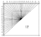
도 4는 HEVC에서의 33개의 방향성 인트라 예측 모드와 2개의 비방향성(non-directional) 인트라 예측 모드의 일례를 나타내는 도면이다.
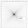
도 5는 JEM에서의 인트라 모드에 대한 예측 방향을 나타내는 도면이다. 실선은 JEM 모드의 서브 세트인 HEVC 인트라 모드 방향에 해당한다. 번호는 HEVC에 대한 모드 번호이다.
도 6은 위치 의존 인트라 예측 조합의 개략도이다.
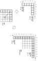
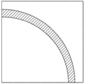
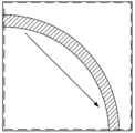
도 7a 내지 도 7d는 상이한 인트라 모드 파티션 방법을 비교하는 개략도이다. 도 7a: 원래의 블록; 도 7b: 하나의 CU 파티션; 도 7c: 4개의 CU 파티션; 도 7d: CU + PU 파티션.
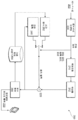
도 8은 제어 포인트 기반 인트라 예측 모듈을 포함하는 하이브리드 비디오 인코더의 블록도이다.
도 9는 제어 포인트 기반 인트라 예측 모듈을 포함하는 하이브리드 비디오 디코더의 블록도이다.
도 10은 인트라 예측 방향의 예시적인 제어 포인트 표현의 개략도이다.
도 11a 내지 도 11d는 2개의 제어 인트라 예측 방향이 적용되는 실시예들에서 제어 포인트의 선택의 개략도이다. 도 11a: 수평 제어 포인트 선택; 도 11b: 수직 제어 포인트 선택; 도 11c: 대각선 제어 포인트 선택; 도 11d: 안티 대각선 제어 포인트 선택.
도 12a 및 도 12b는 3개의 제어 포인트가 적용되는 실시예들에서 인트라 예측 방향 도출의 개략도이다. 도 12a: PU 레벨에서의 도출; 도 12b: TU 레벨에서 도출.
도 13은 예시적인 실시예에서 제어 인트라 예측 방향의 디코더 측 도출의 개략도이다.
도 14는 제어 포인트의 인트라 방향을 사용하는 인트라 예측 신호의 가중 조합을 사용하여 인트라 예측 샘플을 생성하는 개략도이다.
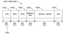
도 15는 코딩된 비트스트림 구조의 일례를 나타내는 도면이다.
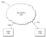
도 16은 예시적인 통신 시스템을 나타내는 도면이다.
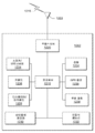
도 17은 일부 실시예들에서 인코더 또는 디코더로서 사용될 수 있는 예시적인 무선 송수신 유닛(wireless transmit/receive unit; WTRU)을 나타내는 도면이다.A more detailed understanding may be had from the following description, which is given by way of example and with reference to the accompanying drawings, which are briefly described below.
1 is a functional block diagram illustrating an example of a block-based video encoder.
2 is a functional block diagram illustrating an example of a block-based video decoder.
Fig. 3 is a diagram showing notations used in the present invention to describe reference samples in intra prediction; Fig.
4 is a diagram showing an example of 33 directional intra prediction modes and two non-directional intra prediction modes in the HEVC.
5 is a diagram showing a prediction direction for the intra mode in the JEM. The solid line corresponds to the HEVC intra mode direction, which is a subset of the JEM mode. The number is the mode number for HEVC.
6 is a schematic diagram of a position-dependent intra prediction combination.
7A to 7D are schematic diagrams comparing different intra mode partitioning methods. 7a: original block; 7b: one CU partition; Figure 7c: Four CU partitions; 7d: CU + PU partition.
8 is a block diagram of a hybrid video encoder including a control point based intra prediction module.
9 is a block diagram of a hybrid video decoder including a control point based intra prediction module.
10 is a schematic diagram of an exemplary control point representation of an intra-prediction direction.
Figures 11A-11D are schematic diagrams of the selection of control points in embodiments in which two control intra prediction directions are applied. 11a: horizontal control point selection; 11b: vertical control point selection; 11C: diagonal control point selection; 11d: Anti-diagonal control point selection.
12A and 12B are schematic diagrams of derivation of an intra-prediction direction in embodiments where three control points are applied. 12a: derivation at PU level; Figure 12b: Derived from the TU level.
13 is a schematic diagram of decoder side derivation of a control intra prediction direction in an exemplary embodiment;
14 is a schematic diagram for generating an intra prediction sample using a weighted combination of intra prediction signals using the intra direction of the control point.
15 is a diagram showing an example of a coded bit stream structure.
16 is a diagram illustrating an exemplary communication system.
17 is a diagram illustrating an exemplary wireless transmit / receive unit (WTRU) that may be used as an encoder or decoder in some embodiments.
예시적인 블록 기반 인코딩 및 디코딩 시스템 및 방법.Exemplary block-based encoding and decoding systems and methods.
본 명세서에 개시된 실시예들은 HEVC 및 JEM 소프트웨어와 마찬가지로, 블록 기반 하이브리드 비디오 코딩 프레임워크 상에 구축된다.The embodiments disclosed herein are built on a block-based hybrid video coding framework, similar to HEVC and JEM software.
도 1은 블록 기반 하이브리드 비디오 인코딩 시스템의 기능 블록도이다. 입력 비디오 신호(102)는 블록 단위로 처리된다. HEVC에서, 고해상도(1080p 이상) 비디오 신호를 효율적으로 압축하기 위해 확장된 블록 크기("코딩 유닛(coding unit)" 또는 CU라고 함)가 사용된다. HEVC에서는 CU는 64x64 픽셀까지 가능하며, JEM에서는 큰 해상도의 비디오(예를 들어, 720p 이상)의 인코딩을 위해 256x256까지의 더 큰 블록 크기가 허용된다. CU는 별도의 예측 방법이 적용되는 예측 유닛(prediction unit; PU)으로 더 분할될 수 있다. 각각의 입력 비디오 블록(MB 또는 CU)에 대해, 공간 예측(160) 및/또는 시간 예측(162)이 수행될 수 있다. 공간 예측(또는 "인트라 예측")은 동일한 비디오 픽처/슬라이스에서 이미 코딩된 이웃하는 블록으로부터의 픽셀을 사용하여 현재의 비디오 블록을 예측한다. 공간 예측은 비디오 신호에 내재하는 공간 중복을 줄인다. 시간 예측("인터 예측" 또는 "모션 보상 예측"이라고도 함)은 이미 코딩된 비디오 픽처로부터의 재구성된 픽셀을 사용하여 현재 비디오 블록을 예측한다. 시간 예측은 비디오 신호에 내재하는 시간 중복을 줄인다. 주어진 비디오 블록에 대한 시간 예측 신호는 보통 현재 블록과 그 기준 블록 사이의 모션의 양 및 방향을 나타내는 하나 이상의 모션 벡터에 의해 시그널링된다. 또한, (H.264/AVC 또는 HEVC와 같은 최근의 비디오 코딩 표준의 경우와 같이) 다수의 기준 픽처가 지원되는 경우, 각각의 비디오 블록에 대해, 그 기준 픽처 인덱스가 부가적으로 전송되고; 기준 인덱스는 시간 예측 신호가 기준 픽처 저장소(164)에서의 어느 기준 픽처로부터 왔는지를 식별하는 데 사용된다. 공간 및/또는 시간 예측 후에, 인코더 내의 모드 결정 블록(180)은 예를 들어 레이트 왜곡 최적화 방법에 기초하여 최상의 예측 모드를 선택한다. 그런 다음, 예측 블록은 현재 비디오 블록으로부터 차감되고(116); 예측 잔차는 타겟 비트 레이트를 달성하기 위해 변환(104) 및 양자화(106)를 사용하여 무상관화(de-correlate)된다. 양자화된 잔차 계수는 역양자화(110) 및 역변환(112)되어 재구성된 잔차를 형성하고, 그런 다음 재구성된 잔차는 예측 블록에 다시 가산되어(126), 재구성된 비디오 블록을 형성한다. 또한, 디블록킹(de-blocking) 필터 및 적응적 루프 필터(Adaptive Loop Filter)와 같은 인루프 필터링(166)이 재구성된 비디오 블록 상에 적용될 수 있고, 그 후 재구성된 비디오 블록은 기준 픽처 저장소(164)에 입력되어 미래의 비디오 블록을 코딩하는데 사용된다. 출력 비디오 비트스트림(120)을 형성하기 위해, 코딩 모드(인터 또는 인트라), 예측 모드 정보, 모션 정보 및 양자화된 잔차 계수는 모두 엔트로피 코딩 유닛(108)에 전송되어 추가로 압축되고 패킹되어 비트스트림을 형성한다.1 is a functional block diagram of a block-based hybrid video encoding system. The
도 2는 블록 기반 비디오 디코더의 기능 블록도이다. 비디오 비트스트림(202)은 우선 엔트로피 디코딩 유닛(208)에서 언패킹되고 엔트로피 디코딩된다. 코딩 모드 및 예측 정보는 예측 블록을 형성하기 위해 공간 예측 유닛(260)(인트라 코딩된 경우) 또는 시간 예측 유닛(262)(인터 코딩된 경우) 중 하나에 전송된다. 잔차 변환 계수는 역양자화 유닛(210) 및 역변환 유닛(212)에 전송되어 잔차 블록을 재구성한다. 예측 블록 및 잔차 블록은 226에서 함께 합산된다. 또한, 재구성된 블록은 기준 픽처 저장소(264)에 저장되기 전에 인루프 필터링을 거칠 수 있다. 그런 다음, 재구성된 비디오는 디스플레이 디바이스를 구동하기 위해 전송되며 미래의 비디오 블록을 예측하는 데도 사용된다.2 is a functional block diagram of a block-based video decoder. The
HEVC에서의At HEVC 인트라Intra 코딩 툴. Coding tools.
HEVC는 선행 비디오 코딩 표준에 비해 인트라 예측 효율을 향상시키는 여러 코딩 툴들을 통합한다. 이러한 인트라 코딩 툴은 점진적으로 변화하는 샘플 값을 갖는 부드러운 영역뿐만 아니라 상이한 방향 텍스처를 더 정확하게 모델링할 수 있다. 또한, 잠재적 블로킹 아티팩트가 있는 인위적인 에지의 도입을 피하기 위해 설계 중에 DC 및 직접 수평 및 수직 방향에 대한 생성된 인트라 예측의 경계 샘플 및 기준 샘플의 적응적 평활화를 수행하는 추가적인 노력이 이루어졌다.HEVC incorporates several coding tools to improve intra prediction efficiency over previous video coding standards. Such an intra coding tool can more accurately model the different directional textures as well as the soft areas with gradually changing sample values. Further efforts have been made to perform adaptive smoothing of the boundary samples and reference samples of the generated intra-prediction for DC and direct horizontal and vertical directions during design during the design to avoid introduction of artificial edges with potential blocking artifacts.
HEVC의 인트라 코딩에 사용되는 코딩 구조는 코덱의 전체 구조를 밀접하게 따른다. 특히, 하나의 픽처는 인트라 코딩을 수행하는 데 사용되는 기본 쿼드 트리(quad-tree) 분할 영역을 나타내는 다수의 CU로 분할된다. 하나의 CU 내에는 다수의 비중첩 예측 유닛(PU)이 정의될 수 있으며, 각각의 PU는 개별 인트라 예측 모드를 갖는 영역을 지정한다. HEVC에서, 하나의 인트라 코딩된 CU는 두 가지 유형의 PU 파티션, 즉 PART_2Nx2N 및 PART_NxN을 가질 수 있다. PART_2Nx2N은 CU 내의 모든 샘플이 동일한 인트라 예측 모드에 의해 예측된다는 것을 나타내고, PART_NxN은 CU가 4개의 동일한 크기의 PU로 분할된다는 것을 나타내며, 각각의 PU는 자신의 인트라 예측 모드에 의해 예측된다. 주어진 PU는 변환 유닛(transform unit; TU)의 쿼드 트리로 더 분할될 수 있으며, 각각의 TU는 TU 크기의 변환을 갖는 잔차 코딩을 적용하는 기본적인 연산 유닛이다. 부가적으로, HEVC 사양에서, HEVC에서의 모든 인트라 예측 모드의 예측 동작은 인트라 예측의 효율 개선을 위해 예측에 사용된 기준 샘플과 예측 샘플 간의 거리를 최소화하기 위해 TU 단위로 정의된다.The coding structure used for intra coding of HEVC closely follows the overall structure of the codec. In particular, one picture is divided into a number of CUs representing a basic quad-tree partition used to perform intra coding. A plurality of non-overlap prediction units (PU) can be defined in one CU, and each PU specifies an area having a separate intra prediction mode. In HEVC, one intra-coded CU may have two types of PU partitions, PART_2Nx2N and PART_NxN. PART_2Nx2N indicates that all samples in the CU are predicted by the same intra prediction mode, and PART_NxN indicates that the CU is divided into four equal-sized PUs, and each PU is predicted by its intra prediction mode. A given PU may be further divided into quad trees of a transform unit (TU), where each TU is a basic operation unit that applies residual coding with a transform of TU size. Additionally, in the HEVC specification, the prediction operation of all intraprediction modes in the HEVC is defined in units of TU to minimize the distance between the reference sample and the prediction sample used for the prediction to improve the efficiency of intra prediction.
가능한 인트라 예측 모드의 수 때문에, HEVC는 루마 인트라 예측 모드를 코딩할 때 5개의 최고 확률 모드(Most Probable Mode; MPM)를 고려한다. 5개의 MPM 중 2개가 먼저 상부 및 좌측 이웃하는 블록의 인트라 예측 모드를 검출하여 도출되고, 나머지 3개의 MPM은 평면(Planar), DC 및 수직 방향(26)으로 정의된다. 또한, 상부 및 좌측 블록이 동일한 각도 모드를 갖는 경우, 그 방향에 가장 가까운 2개의 이웃 각도 방향이 또한 MPM 리스트에 포함될 것이다.Because of the number of possible intra prediction modes, the HEVC considers the five most probable modes (MPM) when coding the luma intra prediction mode. Two of the five MPMs are derived by first detecting the intra-prediction mode of the upper and left neighboring blocks, and the remaining three MPMs are defined as planar, DC and
인트라 예측 모드. HEVC에서의 모든 인트라 예측 모드에 대해, (도 3에 도시된 바와 같이) 현재 TU의 상부 및 좌측으로부터 이전에 디코딩된 경계 샘플들의 동일한 세트가 예측에 사용된다. 33개의 상이한 각도 방향을 갖는 방향성 예측은 4x4 내지 32x32까지의 다양한 TU 크기에 대해 정의된다. 각도 방향 외에도, 평면 예측(경계에서 도출된 수평 및 수직 기울기를 갖는 점진적으로 변화하는 표면을 가정함) 및 DC 예측(평평한 표면을 가정함)이 또한 사용될 수 있다. 표 1은 모드 인덱스 및 각각의 모드 인덱스와 연관된 인트라 예측 모드를 지정한다. 도 4는 HEVC에서 정의된 바와 같은 기존의 인트라 예측 모드를 나타낸다. 크로마의 경우, 수평, 수직, 평면 및 DC 모드를 비트스트림으로 명시적으로 시그널링할 수 있다; 또한, 크로마 예측 모드는 DM 모드를 통해 루마 예측 모드와 동일하게 나타날 수 있다. Intra prediction mode . For all intra prediction modes in the HEVC, the same set of previously decoded boundary samples from the top and left of the current TU (as shown in Figure 3) is used for prediction. Directional predictions with 33 different angular directions are defined for various TU sizes from 4x4 to 32x32. In addition to the angular orientation, planar prediction (assuming progressively varying surfaces with horizontal and vertical gradients derived at the boundary) and DC prediction (assuming a flat surface) can also be used. Table 1 specifies the mode index and the intra prediction mode associated with each mode index. Figure 4 shows an existing intra prediction mode as defined in HEVC. For chroma, horizontal, vertical, plane and DC modes can be explicitly signaled to the bitstream; In addition, the chroma prediction mode may be the same as the luma prediction mode through the DM mode.

표 1. 인트라 예측 모드의 사양.Table 1. Intra prediction mode specifications.
기준 샘플 평활화. HEVC에서, 인트라 예측에 사용되는 기준 샘플은 때때로 TU 크기 및 인트라 예측의 방향성에 따라 3-탭 평활화 필터[1, 2, 1]/4에 의해 필터링된다. 32x32 TU의 경우, 직접 수평 및 수직을 제외한 모든 각도 모드가 필터링된 기준 샘플을 사용한다. 16x16 TU의 경우, 필터링된 기준 샘플을 사용하지 않는 인트라 모드는 수평 및 수직에 가장 가까운 4개의 모드(9, 11, 25 및 27)로 확장된다. 8x8 및 더 작은 TU의 경우, 대각선 모드(2, 18 및 34)만이 예측을 위해 필터링된 기준을 사용한다. 부가적으로, TU 크기가 8x8 이상인 경우, 기준 평활화가 또한 평면 모드에 적용된다. Reference sample smoothing . In the HEVC, the reference samples used for intra prediction are sometimes filtered by a 3-tap smoothing filter [1, 2, 1] / 4 depending on the TU size and the directionality of the intra prediction. For a 32x32 TU, all angle modes except direct horizontal and vertical use filtered reference samples. For a 16x16 TU, an intra mode that does not use the filtered reference sample extends to four modes (9, 11, 25, and 27) that are closest to horizontal and vertical. For 8x8 and smaller TU, only
JEM에서의 인트라 코딩 툴. 일반적으로, HEVC 인트라 코딩의 기본 구조는 JEM에서 변경되지 않고 남아있고, 확장된 인트라 예측 방향, 4-탭 인트라 보간, 확장된 경계 평활화, 위치 의존 인트라 예측 조합, 모드 의존 비분리형 2차 변환 및 적응적 기준 필터링을 포함하는, 인트라 예측과 관련된 몇몇 모듈들이 더 확장 및/또는 개선된다. 다음에서는 JEM의 여러 가지 인트라 코딩 툴을 간단히 검토한다. At JEM Intra coding tools . In general, the basic structure of HEVC intra coding remains unaltered in JEM and can be extended to include extended intra prediction directions, 4-tap intra-interpolation, extended boundary smoothing, position dependent intra prediction combinations, Several modules related to intra prediction, including adaptive filtering, are further expanded and / or improved. In the following, we will briefly review the various intra-coding tools of JEM.
확장된 인트라 예측 방향. 미가공 비디오에 존재하는 더 세밀한 에지 방향을 포착하기 위해, JEM에서는 각도 인트라 예측 모드의 수가 HEVC의 33에서 65로 확장된다. 도 5는 JEM에서 정의된 바와 같은 인트라 예측 모드를 나타내고, 여기서는 HEVC에 비해 새로운 방향성 모드가 점선으로 강조되고 평면 모드 및 DC 모드는 동일하게 유지된다. HEVC와 같이, 확장된 방향성 인트라 예측 모드는 모든 TU 크기 및 루마 및 크로마 인트라 예측 모두에 적용된다. Extended intra prediction direction . In order to capture the finer edge directions present in raw video, the number of angular intra prediction modes in JEM is extended from 33 to 65 in HEVC. Figure 5 shows an intra prediction mode as defined in JEM where a new directional mode is emphasized as a dotted line compared to HEVC and the planar mode and the DC mode remain the same. Like HEVC, the extended directional intra prediction mode applies to all TU size and luma and chroma intra prediction.
방향성 인트라 모드의 증가된 수를 수용하기 위해, 개선된 인트라 모드 코딩 방법은 6개의 MPM을 사용한다. 6개의 MPM의 세트를 도출하기 위해, 좌측 및 상부 이웃하는 블록의 인트라 모드가 체크된다. HEVC의 경우에서와 같이, 상부 및 좌측 이웃하는 블록의 인트라 모드를 직접 사용하는 대신에, 상부 이웃하는 행 및 좌측 이웃하는 열을 따라 가장 빈번하게 사용되는 인트라 모드가 계산되어, 좌측 및 상부 이웃 모드로서 각각 사용된다. 다음으로, 실제 6개의 MPM을 도출하기 위해, HEVC에서 사용된 것과 동일한 규칙이 적용되어 먼저 3개의 MPM을 획득하고; 그런 다음, 나머지 3개의 MPM은 MPM의 리스트에 이미 포함되어 있는 각도 모드에 (예측 방향으로) 가장 가까운 3개의 인트라 모드로 정의된다. 표 2는 현재 JEM에서 사용되는 MPM 도출 방법을 나타내며, 여기서 L 및 A는 각각 좌측 및 상부 이웃하는 블록의 가장 빈번하게 사용되는 인트라 예측 모드를 지정하고, Max 및 Min은 각각 좌측 및 상부 이웃하는 블록의 인트라 예측 모드의 최대 및 최소를 지정한다.To accommodate the increased number of directional intra modes, the improved intra mode coding method uses six MPMs. To derive a set of six MPMs, the intra mode of the left and top neighboring blocks is checked. Instead of directly using the intra modes of the upper and left neighboring blocks, as in the case of HEVC, the most frequently used intra modes along the upper neighbor row and the left neighbor column are computed so that the left and upper neighbor modes Respectively. Next, in order to derive the actual six MPMs, the same rules as those used in the HEVC are applied to obtain three MPMs first; The remaining three MPMs are then defined as the three intra modes closest to the angle mode (in the prediction direction) already included in the list of MPMs. Table 2 shows the MPM derivation method currently used in JEM, where L and A designate the most frequently used intra prediction modes of the left and top neighboring blocks, respectively, Max and Min are the left and top neighboring blocks The maximum and minimum of the intra prediction modes of the intra prediction mode.
R≠평면L <>
R ≠ plane
표 2. JEM에서의 6개의 MPM 도출.Table 2. Derivation of six MPMs in JEM.
기준 샘플 적응적 필터링. HEVC 인트라 예측에서, 일부 인트라 예측 모드의 경우 기준 샘플을 평활화하기 위해 저역 통과 필터[1, 2, 1]/4가 사용된다. 평활화 필터링이 적용되는 인트라 예측 모드의 수는 블록 크기 및 예측 모드에 의존한다. 특히, 32x32 블록의 경우, 수평 및 수직을 제외한 모든 각도 모드는 필터링된 기준을 사용하고; 16x16 블록의 경우, 필터링된 기준을 사용하지 않는 모드는 수평 및 수직에 가장 가까운 4개의 모드(9, 11, 25, 27)로 확장되며; 8x8 블록의 경우, 대각선 모드(2, 18, 34)만 필터링된 기준을 사용한다. 8x8 이상의 블록 크기의 경우, 평면 모드를 사용하는 경우에도 평활화가 적용된다. Reference sample adaptive Filtering . In HEVC intra prediction, low-pass filters [1, 2, 1] / 4 are used to smooth reference samples in some intra prediction modes. The number of intra prediction modes to which smoothing filtering is applied depends on the block size and the prediction mode. In particular, for 32x32 blocks, all angle modes except horizontal and vertical use filtered criteria; In the case of a 16x16 block, the modes that do not use the filtered reference extend to four modes (9, 11, 25, 27) that are closest to horizontal and vertical; For 8x8 blocks, only the diagonal mode (2, 18, 34) uses the filtered reference. For block sizes greater than 8x8, smoothing is also applied when using planar mode.
블록 크기 및 예측 방향성에 기초하여 선택적으로 기준 샘플 평활화를 적용하는 것은, 기준 샘플 어레이의 에지에 의해 야기된 윤곽 아티팩트를 감소시키도록 동작할 수 있다. JEM에서, 인트라 예측 효율을 향상시키기 위해, 기준 샘플 적응적 필터링(reference sample adaptive filtering; RASF)에 의해 인트라 예측을 위한 기준 샘플을 평활화하도록 이하와 같은 2 세트의 저역 통과 필터가 적용된다. Applying the reference sample smoothing selectively based on the block size and the predictive directionality can operate to reduce contour artifacts caused by the edges of the reference sample array. In JEM, to improve the intra prediction efficiency, the following two sets of low-pass filters are applied to smoothen the reference samples for intra prediction by reference sample adaptive filtering (RASF).
● 계수가 [1, 2, 1]/4인 3-탭 LPF(HEVC의 디폴트 기준 평활화 필터),● A 3-tap LPF (default reference smoothing filter of HEVC) with coefficients [1, 2, 1] / 4,
● 계수가 [2, 3, 6, 3, 2]/16인 5-탭 LPF.● A 5-tap LPF with coefficients of [2, 3, 6, 3, 2] / 16.
RSAF가 달성할 수 있는 이득을 최대화하기 위해, 2개의 기준 평활화 필터의 선택이 TU 레벨에서 수행된다.In order to maximize the gain that RSAF can achieve, the selection of two reference smoothing filters is performed at the TU level.
데이터 은닉(data hiding)은 주로 워터마킹에 사용되는 기술이다. HEVC에서, 이 방법은 TU 계수 그룹(coefficients group; CG)의 최상위 계수의 부호를 CG 계수의 절대값의 패리티에 숨기도록 적용되고, 이는 부호 비트 숨김(sign bits hiding; SBH)이라고 한다. RSAF 플래그 시그널링의 오버 헤드를 줄이기 위해, 주어진 TU에 대한 기준 필터링이 인에이블되는지 여부를 나타내는 플래그를 해당 TU의 변환 계수에 숨기기 위해 데이터 은닉이 사용된다. 주어진 TU의 모든 계수를 사용하는 SBH와 달리, RSAF는 TU 내의 홀수 위치에 있는 변환 계수만을 사용하여 필터링 플래그의 값을 숨긴다.Data hiding is a technique used primarily for watermarking. In HEVC, this method is applied to hide the sign of the highest coefficient of the TU coefficient group (CG) in the parity of the absolute value of the CG coefficient, which is called sign bits hiding (SBH). To reduce the overhead of RSAF flag signaling, data concealment is used to hide the flag indicating whether reference filtering for a given TU is enabled in the transform coefficients of that TU. Unlike the SBH which uses all the coefficients of a given TU, RSAF only hides the value of the filtering flag using the transform coefficients at odd positions in the TU.
위치 의존 인트라 예측 조합. HEVC에서, 예측 모드 및 블록 크기에 따라, 기준 경계 픽셀의 필터링되지 않은 세트 또는 필터링된 세트 중 어느 하나로부터 인트라 예측이 계산된다. 위치 의존 인트라 예측 조합(position dependent intra prediction combination; PDPC)은 필터링된 기준과 필터링되지 않은 기준으로부터 계산된 예측 샘플의 가중 조합을 사용하여 이 방법을 확장하고, 여기서 가중치는 예측 모드 및 픽셀 위치에 의존한다. 도 6에 도시된 바와 같이 인트라 예측기를 정의하기 위해 사용된 표기법에 기초하여, r 및 s는 각각 필터링되지 않은 기준 샘플 및 필터링된 기준 샘플을 나타낸다. q[x, y]는 HEVC에서 정의된 바와 같이 필터링된 기준 s로부터 도출된 방향성 예측이지만, DC 및 직접 수평 및 수직 인트라 방향에 대한 경계 필터를 디스에이블한다. 값 x 및 y는 블록 경계로부터의 수평 및 수직 거리이다. 우측 비트 시프트 연산을 나타내기 위해 ">>"를 사용하여, 필터링되지 않은 기준 샘플 r[x, y]의 가중된 값과 예측 신호 q[x, y]를 결합하는 새로운 예측 p[x, y]은 다음과 같이 도출된다. Location dependent intra prediction combination . In the HEVC, the intra prediction is calculated from either the unfiltered set of the reference boundary pixels or the filtered set, depending on the prediction mode and the block size. A position dependent intra prediction combination (PDPC) extends this method using a weighted combination of filtered and predicted samples calculated from unfiltered bases, where the weights depend on the prediction mode and the pixel location do. Based on the notation used to define the intra-predictor, as shown in FIG. 6, r and s denote the filtered and unfiltered reference samples, respectively. q [x, y] is the directional prediction derived from the filtered reference s as defined in HEVC, but disables the boundary filters for DC and direct horizontal and vertical intra directions. The values x and y are the horizontal and vertical distances from the block boundary. X [y] to combine the weighted value of the unfiltered reference sample r [x, y] with the prediction signal q [x, y] using ">>" to indicate the right bit shift operation. ] Is derived as follows.

여기서, ![]()
![]()
![]()
![]()
는 정규화 요소이다.Is a normalization factor.
필터링된 기준은 이항 저역 통과 필터를 사용하여 도출되는데, 이들이 정수 계산을 위해 쉽게 조정될 수 있고, 가우스 필터와 비슷하기 때문이다. 예측 파라미터(![]()
![]()
모드 의존 비분리형 2차 변환. 공간적으로 이웃하는 샘플들 간의 상관관계는 시간 영역에서의 상관관계보다 훨씬 적기 때문에, 일반적으로 인트라 예측으로부터 생성된 잔차 샘플 내에 강한 상관관계가 있다. 인트라 코딩 효율을 더욱 향상시키기 위해, 모드 의존 비분리형 2차 변환(non-separable secondary transform; NSST)이 현재 JEM에 적용된다. NSST는 인트라 예측의 각각의 4x4 변환 계수 블록에 비분리형 변환을 적용한다. 구체적으로, 0에서 3까지의 CU 레벨 인덱스는 명시적으로 어떤 미리 정의된 2차 변환이 적용되는지 식별하기 위해 시그널링된다. 인덱스가 0이면, 2차 변환이 사용되지 않고; 그렇지 않으면, 3개의 미리 정의된 4x4 비분리형 변환 중 하나가 사용된다. 하나의 TU의 각각의 4x4 계수 블록에 대해, CU-레벨 인덱스에 의해 식별된 4x4 비분리형 변환이 적용된다. 또한, CU 레벨 NSST 플래그는 현재 CU에 적어도 하나의 0이 아닌 변환 계수가 있는 경우에만 시그널링된다. mode Dependent non-separable quadratic transformation . Because the correlation between spatially neighboring samples is much less than the correlation in the time domain, there is generally a strong correlation within the residual samples generated from intra prediction. In order to further improve the intra coding efficiency, a mode-independent non-separable secondary transform (NSST) is currently applied to JEM. The NSST applies a non-separable transform to each 4x4 transform coefficient block of the intra prediction. Specifically, a CU level index from 0 to 3 is explicitly signaled to identify which predefined quadratic transformation is applied. If the index is 0, the secondary transformation is not used; Otherwise, one of the three predefined 4x4 non-separable transforms is used. For each 4x4 coefficient block of one TU, the 4x4 non-separable transform identified by the CU-level index is applied. Also, the CU level NSST flag is signaled only if there is at least one non-zero transform coefficient in the current CU.
비분리형 변환을 적용하기 위해, 하나의 4x4 입력 블록 X가 먼저 벡터 ![]()
![]()


비분리형 변환은 ![]()
![]()
![]()
![]()
![]()
![]()
크로마 인트라 예측을 위한 크로스 컴포넌트 예측. 크로스 컴포넌트 상관관계를 탐색하여 코딩 성능을 향상시킬 수 있다. JEM에서는, 크로마 인트라 예측을 위해 크로스 컴포넌트 선형 모델(Linear Model; LM) 예측 모드가 사용된다. LM 예측 모드에서, 다음과 같은 선형 모델을 사용하여 동일한 블록의 재구성된 루마 샘플에 기초하여 크로마 샘플을 예측한다. Chroma Cross component prediction for intra prediction . The cross-component correlation can be searched to improve the coding performance. In JEM, a cross component linear model (LM) prediction mode is used for chroma intra prediction. In the LM prediction mode, the following linear model is used to predict the chroma samples based on the reconstructed luma samples of the same block.
![]()
![]()
여기서, ![]()
![]()
![]()
![]()
![]()
![]()
![]()
![]()
부가적으로, LM 예측 모드는 또한 2개의 크로마 컴포넌트들 사이의 상관관계를 사용하는데, 즉 Cr 컴포넌트는 Cb 컴포넌트로부터 예측된다. 재구성된 샘플 신호를 사용하는 대신에, 크로스 컴포넌트 예측이 잔차 영역에 적용된다. 이는 최종 Cr 예측을 형성하기 위해 가중 재구성된 Cb 잔차를 원래의 Cr 인트라 예측에 합산함으로써 구현된다.Additionally, the LM prediction mode also uses the correlation between the two chroma components, i. E. The Cr component is predicted from the Cb component. Instead of using the reconstructed sample signal, cross-component prediction is applied to the residual region. This is implemented by adding the weighted reconstructed Cb residuals to the original Cr intra prediction to form a final Cr prediction.
![]()
![]()
스케일링 인자 ![]()
![]()
![]()
![]()
![]()
![]()
![]()
![]()
인트라Intra 예측 코딩 오버 헤드. Predictive coding overhead.
상기 논의된 바와 같이, 인트라 예측을 위해 지원되는 방향들의 수를 증가시킴으로써 HEVC 및 JEM에서의 인트라 코딩에 대해 높은 코딩 효율이 달성될 수 있다. 또한, CU는 다수의 비중첩 PU로 더 분할될 수 있고, 각각의 PU는 상이한 인트라 예측 모드를 가질 수 있다. 이러한 인트라 예측 방향의 PU 기반 표현은 특히 상이한 방향 에지를 갖는 영역에 대해 양호한 코딩 효율을 제공한다. 그러나 미가공 콘텐츠에서, 한 객체의 에지는 방향의 특정 범위를 따라 점진적으로 변화할 수 있고, 이는 사각형으로 제한되는 CU/PU 파티션의 형상과 항상 완벽하게 정렬하는 것은 아니다. 그러므로, 예측된 텍스처 방향을 객체의 실제 에지 방향과 정렬시키기 위해, 영역을 상이한 인트라 예측 방향을 갖는 작은 CU/PU로 분할할 때, 많은 양의 시그널링 오버 헤드(예를 들어, CU 파티션의 깊이, PU 파티션 유형 및 인트라 예측 방향를 나타내는 비트)가 소비된다. 전술한 문제를 설명하기 위해, 도 7a 내지 도 7d는 인트라 코딩을 위한 몇몇 파티션 방법의 비교를 도시한다. 도 7a 내지 도 7d에서, 현재 영역은 0°(직접 수평)에서 90°(직접 수직)까지 점진적으로 변화하는 에지를 따른 경계 샘플을 갖는 도 7a의 호형 객체(패턴화된 줄무늬로 둘러싸임)를 포함하는 16x16 블록인 것으로 가정된다. 도 7b에서, 전체 영역은 하나의 단일 인트라 예측 방향에 의해 하나의 CU(파선으로 둘러싸임)로서 코딩되지만; 블록 내에서 상이한 방향의 에지 상에 위치된 샘플은 정확하게 예측될 수 없다. 도 7c는 전체 영역을 4개의 CU(파선으로 둘러싸임)로 분할하고, 각각의 CU는 자신의 방향에 의해 예측되며; 결과적으로, 정확하게 예측된 샘플의 수는 증가한다. 도 7d는 CU(파선으로 둘러싸임)와 PU(점선으로 둘러싸임) 파티션이 모두 적용되는 파티션 구조를 도시한다. 이 방법은 각각의 CU/PU에 상이한 인트라 예측 모드를 할당함으로써 인트라 예측 정확도를 더욱 증가시킨다. 그러나 앞서 언급한 바와 같이, 이 방법의 불이익은 비트스트림에서 파티션 구조 및 인트라 예측 방향을 나타내기 위해 많은 수의 비트가 시그널링되어야 한다는 것이다.As discussed above, high coding efficiency can be achieved for intra coding in HEVC and JEM by increasing the number of directions supported for intra prediction. Further, the CU may be further divided into a plurality of non-overlapping PUs, and each PU may have a different intra prediction mode. This PU-based representation of the intra-prediction direction provides good coding efficiency especially for regions having different direction edges. In raw content, however, the edge of an object may gradually change along a particular range of orientations, which is not always perfectly aligned with the shape of the CU / PU partition bounded by the rectangle. Therefore, when splitting an area into small CUs / PUs with different intraprediction directions to align the predicted texture direction with the object's actual edge direction, a large amount of signaling overhead (e.g., depth of CU partitions, PU partition type and a bit indicating the intra prediction direction) are consumed. To illustrate the foregoing problem, Figures 7A-7D illustrate a comparison of some partitioning methods for intra-coding. In Figures 7A-7D, the current area is an arc object (surrounded by patterned stripes) of Figure 7A with boundary samples along edges that gradually change from 0 [deg.] (Direct horizontal) to 90 [deg. Lt; RTI ID = 0.0 > 16x16 < / RTI > In Figure 7b, the entire region is coded as one CU (surrounded by a dashed line) by one single intra prediction direction; Samples located on edges in different directions within a block can not be accurately predicted. FIG. 7C shows an entire area divided into four CUs (surrounded by dashed lines), each CU being predicted by its own direction; As a result, the number of correctly predicted samples increases. 7D shows a partition structure in which both a CU (surrounded by a dashed line) and a PU (surrounded by a dotted line) partition are applied. This method further increases intra prediction accuracy by assigning a different intra prediction mode to each CU / PU. However, as mentioned above, the disadvantage of this method is that a large number of bits must be signaled to indicate the partition structure and intra prediction direction in the bitstream.
제어 포인트 기반 Control point based 인트라Intra 예측. prediction.
예측 방향의 제어 포인트 표현에 기초한 인트라 코딩을 위한 시스템 및 방법이 본 명세서에 개시되어 있다. 제안된 시스템 및 방법은 블록 파티션 및 인트라 예측 모드의 시그널링 오버 헤드를 실질적으로 증가시키지 않으면서 인트라 예측 방향의 정밀도를 증가시킴으로써 인트라 코딩의 효율을 향상시킬 수 있다. 예시적인 방법에서, 비디오 블록 내의 샘플의 인트라 예측 방향은 현재 블록에 대한 제어 인트라 예측 방향의 세트로부터 도출된다. 또한, 제어 포인트 기반 인트라 예측이 인에이블되는지 여부를 나타내기 위해 플래그가 시그널링될 수 있다. 제어 포인트 기반 인트라 예측이 인에이블되는 경우, 현재 블록에 대한 제어 포인트의 인트라 모드는 디코더에 전송될 수 있고, 블록 내의 샘플의 인트라 모드는 제어 포인트 인트라 방향으로부터 도출된다. 현재 블록에서 샘플의 텍스처가 방향을 변경하는 경우, 제어 포인트 기반 인트라 예측은 블록 내부의 샘플에 대한 인트라 예측 방향의 양호한 추정을 제공할 수 있다. 제어 포인트 기반 인트라 예측 시스템 및 방법은 비교적 큰 인트라 코딩 유닛(CU) 및 예측 유닛(PU)을 사용할 수 있으므로, CU/PU 파티션 및 인트라 방향 정보를 시그널링하기 위해 사용되는 오버 헤드를 감소시킨다.Systems and methods for intra coding based on control point representations of prediction directions are disclosed herein. The proposed system and method can improve the efficiency of intra coding by increasing the precision of the intra prediction direction without substantially increasing the signaling overhead of the block partition and intra prediction modes. In an exemplary method, an intra-prediction direction of a sample in a video block is derived from a set of control intra-prediction directions for the current block. In addition, a flag may be signaled to indicate whether control point based intra prediction is enabled. When control point based intra prediction is enabled, the intra mode of the control point for the current block can be sent to the decoder, and the intra mode of the sample in the block is derived from the control point intra direction. If the texture of the sample in the current block changes direction, the control point based intra prediction can provide a good estimate of the intra prediction direction for the sample inside the block. The control point based intra prediction system and method can use a relatively large intra coding unit (CU) and prediction unit (PU), thereby reducing the overhead used to signal the CU / PU partition and intra direction information.
상기 논의된 바와 같이, PU 기반 인트라 방향 시그널링에 있어서, 인트라 방향의 적응은 PU 파티션의 정사각형 형상에 의해 제한된다. 로컬 객체 에지(들)은 블록 내에서 방향을 점진적으로 변화시킬 수 있기 때문에, 인트라 예측 방향을 로컬 객체 에지(들)과 정렬시키기 위해, 현재 블록을 작은 PU로 분할하기 위해서는 일반적으로 많은 양의 오버 헤드가 필요하다. 이 문제를 해결하기 위해, 인트라 예측 방향의 새로운 제어 포인트 기반 표현 방법이 본 명세서에 설명된다. 예시적인 실시예들은 블록 파티션 및 인트라 예측 방향의 시그널링 오버 헤드를 실질적으로 증가시키지 않으면서 인트라 예측 방향의 정밀도를 증가시킴으로써 인트라 코딩의 효율을 향상시킬 수 있다. 특히, 예시적인 실시예들에서, 하나 이상의 제어 포인트에서의 인트라 예측 방향이 주어진 비디오 블록에 대해 시그널링된다. 그런 다음, 인접한 샘플들(또는 블록들) 사이의 공간 상관관계를 사용함으로써, 현재 블록 내의 각각의 샘플(또는 샘플들의 서브 블록)의 인트라 예측 방향은 제어 포인트의 인트라 예측 방향으로부터 도출된다. As discussed above, for PU-based intra-directional signaling, the adaptation in the intra direction is limited by the square shape of the PU partitions. Since the local object edge (s) can incrementally change direction within a block, it is generally necessary to divide the current block into small PUs in order to align the intra-prediction direction with the local object edge (s) I need a head. To solve this problem, a new control point based representation method in intra prediction direction is described herein. The exemplary embodiments can improve the efficiency of intra coding by increasing the precision of the intra-prediction direction without substantially increasing the signaling overhead in the block partition and intra-prediction directions. In particular, in exemplary embodiments, an intra-prediction direction at one or more control points is signaled for a given video block. Then, by using spatial correlation between adjacent samples (or blocks), the intra-prediction direction of each sample (or sub-block of samples) in the current block is derived from the intra-prediction direction of the control point.
현재 블록 내의 샘플의 인트라 방향이 제어 포인트에서의 인트라 방향으로부터 직접 도출된다는 것을 고려하면, 블록 당 하나 또는 그 이상의 인트라 방향만 시그널링될 필요가 있기 때문에, 제안된 시스템 및 방법은 인트라 방향의 시그널링 오버 헤드가 비교적 적다. 또한, 제안된 표현 방법이 더 세밀한 세분성 레벨(예를 들어, 샘플 레벨 및 다양한 서브 블록 레벨)에서 인트라 예측 방향의 도출을 허용하기 때문에, 현재의 영역을 작은 CU/PU로 분할할 필요성이 적다. 이것은 큰 인트라 CU/PU의 사용을 증가시킬 수 있으며, 따라서 CU/PU 파티션을 시그널링하기 위해 사용되는 오버 헤드를 감소시킨다. 이들 2 가지 양태 모두는 제어 포인트 인트라 예측을 사용하여 코딩된 비디오 블록의 코딩 성능을 향상시킬 수 있다.Considering that the intra direction of a sample in the current block is derived directly from the intra direction at the control point, the proposed system and method require only one or more intra direction per block to be signaled, Is relatively small. In addition, there is less need to divide the current area into smaller CUs / PUs because the proposed rendering method allows derivation of the intra-prediction direction at a finer granularity level (e.g., sample level and various sub-block levels). This can increase the use of large intra CU / PUs, thus reducing the overhead used to signal the CU / PU partitions. Both of these aspects can improve the coding performance of coded video blocks using control point intra prediction.
제어 포인트 기반 Control point based 인트라Intra 예측 prediction 모드를Mode 사용한 Used 하이브리드hybrid 비디오 코딩. Video coding.
상기 설명된 바와 같이, 예시적인 제어 포인트 기반 인트라 예측 시스템 및 방법은 블록 파티션(예를 들어, CU, PU 및 TU 파티션) 및 인트라 예측 방향의 시그널링 오버 헤드를 감소시킬 수 있다. 제어 포인트 기반 인트라 예측 모델이 영역 내의 로컬 인트라 방향의 양호한 추정을 제공할 수 있는 경우, 블록 경계를 로컬 에지의 변화와 정렬시키기 위해 영역을 작은 CU/PU 파티션으로 분할할 필요가 없고; 또한, 영역 내의 인트라 예측 방향은 명시적으로 시그널링되는 대신에 제어 포인트에서의 방향으로부터 도출될 수 있다. 따라서, 압축 이득이 달성된다. 그러나, 제안된 제어 포인트 기반 인트라 예측 모델은 항상 충분히 정확하지 않을 수 있으며, 큰 예측 오류로 인하여 인트라 예측 효율을 저하시킬 수 있다. 따라서, 코딩 성능을 더욱 향상시키기 위해, 제안된 방법은 특정 블록 레벨에서 적응적으로 선택되도록 제안된다. 일부 실시예들에서, 현재 블록이 제어 포인트 인트라 예측 모드 또는 기존의 인트라 예측 모드 중 하나를 사용하여 예측되는 것을 나타내는 인코더 결정을 디코더에 전송하기 위해 비트스트림에서 플래그가 시그널링된다. 예를 들어, 현재 블록을 예측하는 데 제어 포인트 인트라 예측을 사용할지 여부를 결정하기 위해, 인코더는 HM 및 JEM에서 사용된 라그랑지안(Lagrangian) 최적화 방법과 유사한 방식으로 레이트 왜곡(Rate-Distortion; R-D) 최적화 결정을 사용할 수 있다.As described above, exemplary control point based intraprediction systems and methods can reduce the signaling overhead of block partitions (e.g., CU, PU and TU partitions) and intraprediction directions. If the control point-based intra prediction model can provide a good estimate of the local intra direction within the area, then it is not necessary to divide the area into small CU / PU partitions to align the block boundary with the change in the local edge; In addition, the intra-prediction direction within a region may be derived from the direction at the control point instead of being explicitly signaled. Thus, a compression gain is achieved. However, the proposed control point based intra prediction model may not always be sufficiently accurate, and may cause intra prediction error degradation due to a large prediction error. Therefore, in order to further improve the coding performance, the proposed method is proposed to be adaptively selected at a particular block level. In some embodiments, a flag is signaled in the bitstream to send an encoder decision to the decoder indicating that the current block is predicted using either the control point intra prediction mode or the existing intra prediction mode. For example, in order to determine whether to use control point intra prediction to predict the current block, the encoder uses Rate-Distortion (RD) in a manner similar to the Lagrangian optimization method used in HM and JEM, Optimization decisions can be used.
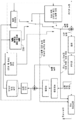
도 8은 제어 포인트 기반 인트라 예측 모듈을 구현하도록 구성된 예시적인 하이브리드 비디오 인코더의 기능 블록도이다. 인트라 코딩된 블록에 대해, 인코더는 종래의 인트라 예측 모드 및 제안된 방법으로부터 선택함으로써, 예를 들어, R-D 최적화를 사용함으로써 인트라 예측 모드를 추정한다. 기존의 비디오 인코더(도 1에 도시된 바와 같음)와 마찬가지로, 인트라 예측 모듈은 이웃하는 블록에 속하는 인접한 재구성된 샘플로부터 블록의 샘플을 예측함으로써 인트라 예측 신호를 생성한다. 원래의 신호는 인트라 예측 신호에 의해 차감되어 공간 중복을 제거하고 대응하는 잔차 신호를 생성한다. 변환 및 양자화는 잔차 신호에 적용되고, 그런 다음 잔차 신호는 엔트로피 코딩되어 비트스트림으로 출력된다. 재구성된 신호를 획득하기 위해, 재구성된 잔차 신호는 역양자화되고 이어서 역변환된다. 재구성된 잔차는 예측 신호에 가산된다. 또한, 인루프 필터링 프로세스, 예를 들어, 디블로킹(de-blocking), SAO 및 ALF가 출력을 위해 재구성된 비디오 신호에 적용된다. 상기 언급한 바와 같이, 코딩 이득을 향상시키기 위해, 제어 포인트 인트라 모드 예측 플래그(예를 들어, control_point_intra_prediction_mode_flag)가 주어진 블록 레벨(예를 들어, CU, PU 또는 TU 레벨)에서 시그널링되어 제안된 제어 포인트 기반 인트라 예측이 현재 블록에 적용되는지 여부를 나타낸다. 그것이 현재 블록에 적용되는 경우, 제어 포인트 기반 인트라 예측 모듈(802)이 본 명세서에 설명된 기술들을 사용하여 인트라 예측을 수행한다.8 is a functional block diagram of an exemplary hybrid video encoder configured to implement a control point based intra prediction module. For intra-coded blocks, the encoder estimates the intra-prediction mode by, for example, using R-D optimization by selecting from the conventional intra-prediction mode and the proposed method. Like the conventional video encoder (as shown in FIG. 1), the intra prediction module generates an intra prediction signal by predicting a sample of a block from adjacent reconstructed samples belonging to a neighboring block. The original signal is subtracted by the intra prediction signal to remove spatial redundancy and generate a corresponding residual signal. The transform and quantization are applied to the residual signal, and the residual signal is then entropy coded and output as a bit stream. To obtain the reconstructed signal, the reconstructed residual signal is dequantized and then inversely transformed. The reconstructed residual is added to the prediction signal. In addition, an in-loop filtering process, e. G. De-blocking, SAO and ALF, is applied to the reconstructed video signal for output. As mentioned above, in order to improve the coding gain, the control point intra mode prediction flag (e.g., control_point_intra_prediction_mode_flag) is signaled at a given block level (e.g., CU, PU or TU level) Indicates whether intra prediction is applied to the current block. If it applies to the current block, the control point based
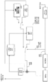
도 9는 제어 포인트 기반 인트라 예측 모듈을 구현하도록 구성된 하이브리드 비디오 디코더의 기능 블록도이다. 도 9의 디코더는 도 8의 인코더에 의해 생성된 비트스트림을 수신하도록 구성될 수 있다. 디코더에서, 비트스트림은 엔트로피 디코더에 의해 파싱된다. 잔차 계수는 역양자화되고 역변환되어 재구성된 잔차를 획득한다. 코딩 모드 및 예측 정보는 공간 예측 또는 시간 예측 중 어느 하나를 사용하여 예측 신호를 획득하기 위해 사용된다. 인트라 코딩된 블록에 대해, 제어 포인트 인트라 모드 예측 플래그(예를 들어, control_point_intra_prediction_mode_flag)가 참이면, 제어 포인트 기반 인트라 예측 모듈(902)을 사용하는 제안된 제어 포인트 기반 인트라 예측 방법에 의해 예측 신호가 생성되고; 그렇지 않으면, 예측 신호는 종래의 인트라 예측 프로세스에 의해 생성된다. 예측 신호 및 재구성된 잔차는 함께 합산되어 재구성된 비디오를 얻는다. 재구성된 비디오는 추가적으로 루프 필터링을 거칠 수 있고, 그 후 미래의 비디오 신호를 디코딩하는 데 사용되기 위해 및/또는 디스플레이되기 위해 기준 픽처 저장소에 저장된다.9 is a functional block diagram of a hybrid video decoder configured to implement a control point based intra prediction module. The decoder of Fig. 9 can be configured to receive the bit stream generated by the encoder of Fig. In the decoder, the bit stream is parsed by an entropy decoder. The residual coefficients are dequantized and inversely transformed to obtain reconstructed residuals. The coding mode and prediction information are used to obtain a prediction signal using either spatial prediction or temporal prediction. For the intra-coded block, if the control point intra mode prediction flag (e.g., control_point_intra_prediction_mode_flag) is true, a prediction signal is generated by the proposed control point based intra prediction method using the control point based
본 명세서에서 제안된 다양한 제어 포인트 기반 인트라 예측 인코딩 및 디코딩 방법들의 몇몇 특징들이 아래에서 보다 상세하게 설명된다. Some features of the various control point based intra prediction encoding and decoding methods proposed herein are described in more detail below.
제어 포인트 기반 Control point based 인트라Intra 예측 prediction 모드의Mode 방향 표현. Expression of direction.
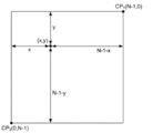
예시적인 코딩 프로세스에서, NxN 블록인 현재 CU를 고려하고, 도 10에 도시된 바와 같은 좌표계를 설정한다. 좌측 상단 코너 (0, 0), 우측 상단 코너 (N-1, 0) 및 좌측 하단 코너 (0, N-1) 각각은 CP0, CP1 및 CP2로 표시된 3개의 제어 포인트로서의 역할을 한다. 위치(x, y)에 위치하는 타겟 샘플은 인트라 예측 방향을 추정하고자 하는 현재 샘플을 지정한다. ![]()
![]()
![]()
![]()

여기서, ![]()
![]()
삼각형 보간이 사용되는 예시적인 실시예에서, 수학식(7)의 3개의 제어 포인트와 관련된 보간 커널 함수는 다음과 같다.In an exemplary embodiment in which triangular interpolation is used, the interpolation kernel function associated with the three control points in equation (7) is:

타겟 포인트가 CP1, CP0 및 CP2에 의해 형성된 삼각형 내에 위치하는 경우(도 10에서 그림자 영역 내의 샘플), 삼각형 보간 결과는 제어 포인트에 의해 제한된 범위 내에 있을 것이다. 타겟 포인트가 삼각형 밖에 있는 경우(도 10에서 빈 영역의 샘플), 삼각형 보간 결과는 외삽되고 제어 포인트에 의해 제한된 범위 밖에 있을 수 있기 때문에 유효한 범위로 클리핑될 수 있다.If the target point is located within a triangle formed by CP 1 , CP 0 and CP 2 (a sample in the shadow region in FIG. 10), the triangular interpolation result will be within a limited range by the control point. If the target point is outside a triangle (a sample of an empty area in FIG. 10), the triangular interpolation result may be clipped to a valid range because it may be extrapolated and out of the limited range by the control point.
다른 예에서, 이중 선형 보간이 사용된다. 이 경우, 3개의 제어 포인트의 보간 커널 함수는 다음과 같이 주어진다.In another example, bilinear interpolation is used. In this case, the interpolation kernel functions of the three control points are given as follows.

수학식(7) 내지 수학식(9)에 도시된 바와 같이, 제안된 제어 포인트 기반 인트라 방향 도출 방법의 보간 프로세스는 (N-1) 또는 (N-1)2에 의한 나누기를 수반할 수 있다. 비디오 블록 크기 N이 일반적으로 2의 거듭제곱인 것을 고려하면, (N-1) 또는 (N-1)2에 의한 나누기는 보통 비트 시프트 연산으로 구현될 수 없으므로 바람직하지 않은 계산 복잡성을 필요로 한다. 일부 실시예들에서, 나누기를 보다 효율적으로 수행하기 위해, 고정 소수점 근사치가 사용되어 결과를 계산할 수 있다. 일반성을 잃지 않고, (N-1)에 의한 나누기를 예로서 고려한다. 이 나누기는 2개의 정수 값 M과 B로 근사화될 수 있고, 다음과 같이 나타날 수 있다.As shown in the equations (7) to (9), the interpolation process of the proposed method of deriving the control point-based intra direction can involve division by (N-1) or (N-1) 2 . Considering that the video block size N is typically a power of two , division by (N-1) or (N-1) 2 usually can not be implemented with bit shift operations and therefore requires undesirable computational complexity . In some embodiments, a fixed-point approximation can be used to compute the result to more efficiently perform the division. Without loss of generality, the division by (N-1) is considered as an example. This division can be approximated by two integer values M and B, and can be expressed as:

따라서, 일부 실시예들에서, 나누기는 M에 의한 곱셈과 그 다음에 우측으로의 B의 비트 시프트로서 구현될 수 있다.Thus, in some embodiments, the division may be implemented as a multiplication by M followed by a bit shift of B to the right.
대안적으로, 일부 실시예들에서, 효율적인 나누기를 촉진하기 위해, 제어 포인트 위치는 이웃하는 블록들 사이에 약간 중첩될 수 있다. 구체적으로, 도 10에 정의된 바와 같은 좌표계를 사용하면, 좌측 상단 제어 포인트(CP0)의 위치는 (0,0)에서 변하지 않는다. 그러나 우측 상단 제어 포인트, 좌측 하단 제어 포인트(CP1 및 CP2)의 위치는 블록 경계를 교차하도록 하나의 추가 열과 하나의 추가 행만큼 각각 이동하여 새로운 위치(CP1 및 CP2)는 각각 현재 블록의 우측 및 하부의 이웃하는 블록에 속하는 (N, 0) 및 (0, N)이 될 것이다. 이에 대응하여, 수학식(7) 내지 수학식(9)의 (N-1)의 값은 이 조정 후에 N이 된다. 따라서, N이 2의 거듭제곱인 경우, 수학식(7) 내지 수학식(9)의 나누기는 비트 시프트를 사용하여 구현될 수 있다.Alternatively, in some embodiments, to facilitate efficient partitioning, the control point location may be slightly overlapping between neighboring blocks. Specifically, using the coordinate system as defined in Fig. 10, the position of the upper left control point CP 0 does not change at (0, 0). However, the upper-right control point, the lower left corner control point (CP 1 and CP 2) positioned to block new position by one mobile respectively by adding additional rows of heat and one to cross the border (CP 1 and CP 2) are each present block of (N, 0) and (0, N) belonging to the right and lower neighboring blocks of the block. Correspondingly, the value of (N-1) in the equations (7) to (9) becomes N after this adjustment. Thus, when N is a power of 2, the division of equations (7) through (9) can be implemented using bit shift.
또 다른 실시예에서, 제어 포인트(CP1 및 CP2)는 현재 블록의 우측 상단 코너 및 좌측 하단 코너, 즉 (N-1, 0) 및 (0, N-1)의 위치로부터 각각 획득되지만, 제어 포인트(CP0)는 현재 블록의 좌측 상단의 이웃하는 샘플, 즉 위치(-1, -1)로부터 획득된다. 이 방법으로, 수학식(7) 내지 수학식(9)의 분모가 N이 되고, N이 2의 거듭제곱인 경우, 나누기는 비트 시프트를 사용하여 구현될 수 있다.In yet another embodiment, the control point (CP 1 and CP 2) is the current block on the top right corner and bottom left corner, that is, (N-1, 0) and (0, N-1), but the obtained each from a position, The control point CP 0 is obtained from the neighboring sample at the upper left of the current block, i.e., the position (-1, -1). In this way, if the denominator of equations (7) to (9) is N and N is a power of 2, division can be implemented using bit shift.
제어 포인트의 선택.Selection of control points.
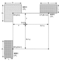
비디오 코딩에서, 인트라 방향의 코딩은 상당량의 비트를 취할 수 있으므로, 특히 낮은 비트 레이트에서 전반적인 코딩 성능에 영향을 미친다. 제어 인트라 방향의 시그널링 오버 헤드는 제안된 제어 포인트 표현의 장점을 무효화시킬 수 있다. 상이한 실시예들에서, 다양한 위치를 갖는 상이한 수의 제어 포인트가 선택될 수 있으며, 이는 비디오 콘텐츠의 상이한 코딩 성능을 초래할 수 있다. 보다 많은 제어 포인트를 사용하는 것은 하나의 비디오 블록 내에서 다양한 인트라 예측 방향의 보다 정확한 추정을 산출할 수 있다는 점에서 유리하다. 그러나 더 많은 수의 제어 포인트는 더 많은 제어 인트라 방향을 전송해야 한다는 것을 고려하면 증가된 오버 헤드로 이어진다. 한편, 제어 포인트의 수가 적으면 시그널링 오버 헤드를 줄일 수 있지만, 항상 정확한 인트라 예측 추정을 제공할 수 있는 것은 아니다. 따라서, 예시적인 실시예들은 상이한 비디오 콘텐츠에 대해 상이한 수의 제어 포인트가 선택될 수 있게 하고, 이러한 제어 포인트의 수는 적절한 시그널링 오버 헤드를 야기하면서 블록 내의 인트라 예측 방향의 정확한 추정을 위해 충분히 크다. 일 실시예에서, 현재 비디오 블록의 좌측 상단 코너 및 우측 상단 코너는 (도 11a에 도시된 바와 같이) 제안된 인트라 예측 도출 방법에 대한 제어 포인트로서 사용된다. 이중 선형 보간이 적용되는 경우, (수학식(9)에 나타난 바와 같은) 제어 포인트의 보간 커널 함수는 다음과 같이 나타낼 수 있다. In video coding, intra-directional coding can take a significant amount of bits, thus affecting overall coding performance, especially at low bit rates. The signaling overhead in the control intra direction may invalidate the advantage of the proposed control point representation. In different embodiments, a different number of control points with different positions may be selected, which may result in different coding performance of the video content. The use of more control points is advantageous in that a more accurate estimate of the various intra prediction directions within a video block can be computed. However, considering that a larger number of control points must transmit more control intra directions, this leads to increased overhead. On the other hand, if the number of control points is small, the signaling overhead can be reduced, but it is not always possible to provide an accurate intra prediction estimation. Thus, the exemplary embodiments allow different numbers of control points to be selected for different video content, and the number of such control points is large enough for accurate estimation of the intra-prediction direction within the block, resulting in appropriate signaling overhead. In one embodiment, the upper left corner and the upper right corner of the current video block are used as control points for the proposed intra prediction prediction derivation method (as shown in FIG. 11A). When bilinear interpolation is applied, the interpolation kernel function of the control point (as shown in equation (9)) can be expressed as:

2개의 제어 포인트가 수평적으로 획득된다는 것을 고려하면, 이 제어 포인트 선택은 수평 방향에서 지배적인 에지를 갖는 비디오 블록의 인트라 방향을 추정하는데 더 효율적이다. 다른 실시예에서, 현재 비디오 블록의 좌측 상단 코너 및 좌측 하단 코너는 (도 11b에 도시된 바와 같이) 제안된 인트라 예측 도출 방법에 대한 제어 포인트로서 사용된다. 이중 선형 보간이 적용되는 것으로 가정하면, (수학식(9)에 나타난 바와 같은) 제어 포인트의 보간 커널 함수는 다음과 같이 나타낼 수 있다.Considering that the two control points are obtained horizontally, this control point selection is more efficient in estimating the intra direction of a video block having a dominant edge in the horizontal direction. In another embodiment, the upper left corner and the lower left corner of the current video block are used as control points for the proposed intra prediction prediction derivation method (as shown in FIG. 11B). Assuming that bilinear interpolation is applied, the interpolation kernel function of the control point (as shown in equation (9)) can be expressed as:

2개의 제어 포인트가 수직적으로 획득되기 때문에, 이 제어 포인트 선택은 수직 방향에서 지배적인 에지를 갖는 비디오 블록의 인트라 방향을 추정하는데 더 효율적이다.Since the two control points are obtained vertically, this control point selection is more efficient in estimating the intra direction of a video block having a dominant edge in the vertical direction.
현재 비디오 블록의 좌측 상단 코너 및 우측 하단 코너가 (도 11c에 도시된 바와 같이) 제어 포인트로서 사용되는 실시예들에서, 보간 커널 함수는 다음과 같이 표현될 수 있다.In embodiments in which the upper left corner and the lower right corner of the current video block are used as control points (as shown in Figure 11C), the interpolation kernel function may be expressed as:

현재 비디오 블록의 우측 상단 코너 및 좌측 하단 코너가 (도 11d에 도시된 바와 같이) 제어 포인트로서 사용되는 경우, 보간 커널 함수는 다음과 같이 표현될 수 있다.If the upper right corner and the lower left corner of the current video block are used as control points (as shown in Figure 11D), then the interpolation kernel function can be expressed as:

제안된 제어 포인트 기반 인트라 예측 도출 방법은 3개의 제어 포인트 또는 2개의 제어 포인트와 같은 콘텐츠의 특성에 기초하여 코딩을 위한 다양한 수의 제어 포인트를 사용할 수 있다. 일부 실시예들에서, 제어 포인트 구성은 픽처 레벨 또는 슬라이스 레벨에서 시그널링된다. 예를 들어, 블록 내의 제어 포인트의 식별은 표 3과 같이 정의될 수 있고, 여기서 block_width 및 block_height는 제어 포인트가 적용되는 블록의 너비와 높이이다. 예시적인 제어 포인트 테이블이 표 4에 정의되어 있으며, 표 4는 제어 포인트의 수 및 각각의 제어 포인트의 위치를 지정한다. 픽처 레벨(예를 들어, 픽처 파라미터 세트) 및 시퀀스 레벨(예를 들어, 시퀀스 파라미터 세트)에서, 표 4에 정의된 다수의 제어 포인트 테이블이 시그널링될 수 있고, 이들은 "control_points_model_id"에 의해 구별될 수 있다. "control_points_model_id"는 또한 슬라이스 레벨 또는 코딩 블록 레벨(예를 들어, CTU, CU)에서 시그널링될 수 있다.The proposed control point based intra prediction prediction derivation method can use various numbers of control points for coding based on characteristics of contents such as three control points or two control points. In some embodiments, the control point configuration is signaled at a picture level or a slice level. For example, the identification of control points in a block can be defined as shown in Table 3, where block_width and block_height are the width and height of the block to which the control point is applied. An exemplary control point table is defined in Table 4, and Table 4 specifies the number of control points and the location of each control point. At a picture level (e.g., a picture parameter set) and a sequence level (e.g., a sequence parameter set), a number of control point tables defined in Table 4 can be signaled and they can be distinguished by "control_points_model_id" have. The " control_points_model_id " may also be signaled at a slice level or a coding block level (e.g., CTU, CU).
표 3. 제어 포인트의 인덱스.Table 3. Indexes for the control points.

표 4. 제어 포인트의 시그널링.Table 4. Signaling of control points.
control_points_model_id: 테이블에 시그널링된 control_point 모델의 ID를 나타냄 control_points_model_id : Indicates the ID of the signaled control_point model in the table
num_control_points: 이 모델에 대한 제어 포인트의 수를 지정함 num_control_points : Specifies the number of control points for this model
CP_Id: 제어 포인트의 표 3에 정의된 ID를 지정함 CP_Id : Specifies the ID defined in Table 3 of the control point.
pos_x: ID가 4인 경우 제어 포인트의 수평 위치를 지정함. 실제 위치는 (pos_x*block_width + 128)/256으로 계산된다. block_width는 블록의 너비이다. pos_x : Specifies the horizontal position of the control point when ID is 4. The actual position is calculated as (pos_x * block_width + 128) / 256. block_width is the width of the block.
pos_y: ID가 4인 경우 제어 포인트의 수직 위치를 지정함. 블록 내의 실제 위치는 (pos_x*block_height + 128)/256으로 계산된다. block_height는 블록의 높이이다. pos_y : Specifies the vertical position of the control point when ID is 4. The actual position in the block is calculated as (pos_x * block_height + 128) / 256. block_height is the height of the block.
수학식(10) 내지 수학식(13)에 관해서는, (N-1)에 의한 효율적인 나누기를 위해 상기 설명된 바와 같은 기술들이 또한 적용될 수 있다는 것을 유념해야 한다.It should be noted that with respect to equations (10) to (13), techniques described above for efficient division by (N-1) can also be applied.
도 11a 및 도 11b에 도시된 바와 같이, 상이한 제어 포인트를 선택하는 것은 상이한 지향성 특성을 나타내는 비디오 영역에 유리할 수 있다. 이러한 측면을 고려하여, 영역 기반 제어 포인트 적응이 적용될 수 있다. 구체적으로, 예시적인 방법에서, (도 11a에 도시된 바와 같은) 수평 제어 포인트 선택은 지배적인 수평 에지 정보를 갖는 영역에 대해 인에이블되고, (도 11b에 도시된 바와 같은) 수직 제어 포인트 선택은 지배적인 수직 에지 정보를 갖는 영역에 대해 인에이블된다. 에지가 수평도 수직도 아닌 비평면 영역에 대해서, (도 10에 도시된 바와 같은) 3개의 제어 포인트가 선택될 수 있다. 하나의 영역에서의 지배적인 에지 방향은 현재 비디오 블록의 재구성된 이웃하는 샘플로부터 결정될 수 있다. 일 실시예에서, 소벨(Sobel) 연산자는 이웃하는 재구성된 샘플의 수평 및 수직 도함수를 계산하는 데 사용된다.As shown in Figs. 11A and 11B, selecting different control points may be advantageous for a video area exhibiting different directivity characteristics. Considering this aspect, region-based control point adaptation can be applied. Specifically, in an exemplary method, a horizontal control point selection (as shown in FIG. 11A) is enabled for an area having dominant horizontal edge information, and a vertical control point selection (as shown in FIG. 11B) And is enabled for regions having dominant vertical edge information. For non-planar regions where the edge is neither horizontal nor vertical, three control points (as shown in Figure 10) may be selected. The dominant edge direction in one region may be determined from the reconstructed neighboring samples of the current video block. In one embodiment, the Sobel operator is used to compute the horizontal and vertical derivatives of neighboring reconstructed samples.

Gy와 Gx 사이의 비율이 미리 정의된 문턱값(T1)보다 큰 경우, 영역은 수평 에지 영역으로 분류될 수 있고; Gy와 Gx 사이의 비율이 미리 정의된 다른 문턱값(T2, T2 << T1)보다 작은 경우, 영역은 수직 에지 영역으로 분류될 수 있으며; 그렇지 않으면, 영역의 에지는 수평도 아니고 수직도 아닌 것으로 간주될 수 있다.If the ratio between G y and G x is greater than a predefined threshold (T 1 ), then the region may be classified as a horizontal edge region; If the ratio between G y and G x is less than another predefined threshold (T 2 , T 2 << T 1 ), then the region may be classified as a vertical edge region; Otherwise, the edge of the region may be considered not to be horizontal nor perpendicular.
다른 실시예에서, 현재 블록 내부의 텍스처의 가능한 방향은 MPM 세트로부터 도출될 수 있다. 예를 들어, MPM 세트의 다수 모드가 수평 방향을 나타내는 경우, 도 11a의 2개의 수평 제어 포인트가 사용될 수 있다. MPM 세트의 다수 모드가 수직 방향을 나타내는 경우, 도 11b의 2개의 수직 제어 포인트가 사용될 수 있다. MPM 모드로부터 수평 또는 수직의 강한 표시가 없는 경우, 도 10의 3개의 제어 포인트가 사용될 수 있다. In another embodiment, possible orientations of the texture within the current block may be derived from the MPM set. For example, if the multiple modes of the MPM set represent a horizontal direction, then the two horizontal control points of Figure 11A may be used. If multiple modes of the MPM set represent a vertical direction, the two vertical control points of FIG. 11B may be used. If there is no horizontal or vertical strong indication from the MPM mode, the three control points of FIG. 10 may be used.
제어 포인트에 기초한 Based on control points 인트라Intra 예측 방향 도출의 Prediction direction 세분성Granularity ..
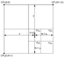
도 10 및 도 11a 내지 도 11d의 실시예들에서, 인트라 예측 방향은 (비디오 블록 내의 각각의 샘플이 자신의 인트라 방향을 가질 수 있도록) 샘플 유닛에 기초하여 도출되지만; 본 발명개시에 따른 인트라 방향 도출 방법은 CU 레벨, PU 레벨 및 TU 레벨과 같은 다양한 레벨에서 수행될 수 있고, 각각의 적응 레벨은 상이한 인트라 방향 적응 능력 및 인코딩/디코딩 복잡성을 제공할 수 있다. 예를 들어, 인트라 예측 방향이 TU 레벨에서 도출되면, 인코더/디코더는 각각의 TU마다 인트라 예측 모드를 도출하고, 하나의 TU 내의 샘플들은 동일한 도출된 인트라 방향을 사용할 것이다. 인트라 예측 방향이 PU에서 도출되면, 인코더 또는 디코더는 각각의 PU마다 인트라 방향을 도출할 필요가 있을 수 있으며, 해당 PU 내부의 모든 TU들은 자신들의 인트라 예측을 위해 동일한 도출된 인트라 방향을 사용할 것이다. 3개의 제어 포인트가 사용되는 경우, 도 12a 및 도 12b는 제안된 제어 포인트 기반 인트라 예측 방법을 위해 PU-레벨(도 12a) 및 TU-레벨(도 12b)에서의 인트라 예측 방향을 도출하는 경우를 도시하며, 여기서 실선 및 파선은 PU와 TU의 경계를 각각 도시한다. 도 12a에서, 타겟 블록은 예측 유닛(PU3)이고, 도 12b에서 타겟 블록은 변환 유닛(TU0)이다. 예시적인 실시예로서, 도 12a 및 도 12b에서, 타겟 블록의 중심 위치는 블록에 대한 인트라 방향을 도출하도록 대표 좌표로서 사용된다. 다른 실시예들에서, 다른 위치가 대표 좌표로서 선택될 수 있다. In the embodiments of Figures 10 and 11A-11D, the intra-prediction direction is derived based on the sample unit (so that each sample in the video block can have its own intra direction); The intra-direction derivation method according to the present disclosure can be performed at various levels such as CU level, PU level and TU level, and each adaptation level can provide different intra-directional adaptive ability and encoding / decoding complexity. For example, if the intra-prediction direction is derived at the TU level, the encoder / decoder derives the intra-prediction mode for each TU, and the samples in one TU will use the same derived intra direction. If the intra prediction direction is derived from the PU, then the encoder or decoder may need to derive the intra direction for each PU, and all TUs within that PU will use the same derived intra direction for their intra prediction. When three control points are used, FIGS. 12A and 12B illustrate the case of deriving the PU-level (FIG. 12A) and the TU-level (FIG. 12B) intraprediction direction for the proposed control point- Where solid lines and dashed lines show the boundaries of PU and TU, respectively. 12A, the target block is the prediction unit PU 3 , and the target block in Fig. 12B is the conversion unit TU 0 . In an exemplary embodiment, in Figures 12A and 12B, the center position of the target block is used as the representative coordinate to derive the intra direction for the block. In other embodiments, other positions may be selected as representative coordinates.
제어 포인트 기반 인트라 예측이 인에이블/디스에이블되는 레벨(예를 들어, control_point_intra_prediction_mode_flag 플래그가 시그널링되는 레벨 또는 제어 포인트가 정의되는 레벨)은 많은 실시예들에서 인트라 방향 도출 레벨보다 높다. 예를 들어, 제어 포인트 기반 인트라 예측은 CU 레벨에서 인에이블될 수 있는 반면, 대응하는 인트라 예측 도출은 PU 레벨, TU 레벨 또는 샘플 레벨에서 수행될 수 있다. 인트라 방향 도출이 제어 포인트를 정의하는 레벨에서 동일하게 수행되는 경우(예를 들어, 모두 CU 레벨), 제안된 방법은 단 하나의 제어 포인트만 필요하기 때문에 일반 인트라 모드로 퇴보하고, 이는 실제로는 블록의 시그널링된 인트라 예측 모드이다.The level at which control point based intraprediction is enabled / disabled (e.g., the level at which the control_point_intra_prediction_mode_flag flag is signaled or the level at which the control point is defined) is higher in many embodiments than the intra directional derived level. For example, control point based intraprediction can be enabled at the CU level, while corresponding intraprediction derivation can be performed at the PU level, TU level, or sample level. If the intra-direction derivation is performed identically at a level that defines the control point (e.g., all at the CU level), the proposed method reverts to the normal intra mode because only one control point is needed, Lt; / RTI > of FIG.
제어 포인트 Control point 인트라Intra 방향 예측 및 Direction prediction and 시그널링Signaling ..
제어 포인트의 인트라 방향의 시그널링 오버 헤드는 제안된 제어 포인트 기반 인트라 예측 모드의 전체 성능에 영향을 미친다. 시그널링 오버 헤드를 줄이기 위해, 본 발명개시의 일 실시예에서, 제어 포인트 인트라 방향을 시그널링하기 위해 HM 및 JEM에서의 기존의 인트라 모드 시그널링 방법을 직접 재사용하는 것이 제안된다. 특히, 각각의 제어 포인트에 대해, MPM 후보 세트는 그것의 좌측 및 상부 이웃의 DC, 평면 및 인트라 모드로부터 생성된다. 제어 인트라 방향이 MPM 후보 중 하나와 동일한 경우, 후보에 대응하는 인덱스만이 전송되고; 그렇지 않으면, 제어 인트라 방향은 고정 길이 코드를 사용하여 시그널링된다. 다른 실시예에서, 비각도(non-angular) 인트라 방향(DC 및 평면)이 제어 포인트 인트라 예측에서 사용되지 않기 때문에, 제어 포인트 기반 인트라 예측 모드가 인에이블될 때 각도 방향만을 포함함으로써 MPM 후보 리스트가 구성될 수 있다. The intra-directional signaling overhead of the control point affects the overall performance of the proposed control point-based intra-prediction mode. To reduce the signaling overhead, in one embodiment of the present disclosure, it is proposed to directly reuse the existing intra mode signaling method in HM and JEM to signal the control point intra direction. Specifically, for each control point, the MPM candidate set is generated from the DC, planar, and intra modes of its left and top neighbors. If the control intra direction is the same as one of the MPM candidates, only the index corresponding to the candidate is transmitted; Otherwise, the control intra direction is signaled using a fixed length code. In another embodiment, since the non-angular intra direction (DC and plane) is not used in the control point intraprediction, the MPM candidate list includes only the angular direction when the control point based intraprediction mode is enabled Lt; / RTI >
차동 코딩(differential coding)은 현대 비디오 코덱에서 다양한 구문 요소의 시그널링 오버 헤드를 감소시키기 위해 널리 사용된다. 예를 들어, HM 및 JEM에서, 차동 코딩은 효율적인 모션 벡터(MV) 코딩을 위해 사용되며, 여기서 하나의 MV는 그것의 공간적 및 시간적 이웃들 중 하나로부터 예측되고 나머지만 전송될 필요가 있다. 이웃하는 비디오 블록의 인트라 예측 방향과 강한 상관관계가 주어지면, 하나의 비디오 블록에 대해, 제어 포인트의 인트라 예측 방향은 매우 유사할 수 있다. 따라서, 본 발명개시의 일 실시예에서, 제어 포인트 인트라 방향을 시그널링하기 위해 차동 코딩을 사용하는 것이 제안된다. 보다 구체적으로는, 제어 포인트들 중 하나(예를 들어, 도 10 및 도 11의 CP0)는 기존의 MPM 기반 인트라 모드 예측 방법에 기초하여 먼저 시그널링된다. 그런 다음, 이 제어 포인트의 인트라 방향을 사용하여 다른 제어 포인트(예를 들면, 도 10 및 도 11의 CP1 및 CP2)의 인트라 방향을 예측한다. 이에 따라, 모드 간의 차이만 시그널링된다.Differential coding is widely used to reduce the signaling overhead of various syntax elements in modern video codecs. For example, in HM and JEM, differential coding is used for efficient motion vector (MV) coding, where one MV is predicted from one of its spatial and temporal neighbors and only the remainder needs to be transmitted. Given a strong correlation with the intra prediction direction of a neighboring video block, for one video block, the intra prediction direction of the control point may be very similar. Thus, in one embodiment of the present disclosure, it is proposed to use differential coding to signal the control point intra direction. More specifically, one of the control points (e.g., CP 0 in FIGS. 10 and 11) is signaled earlier based on the existing MPM-based intra mode prediction method. Then, the intra direction of this control point is used to predict the intra direction of other control points (e.g., CP 1 and CP 2 in FIGS. 10 and 11). Thus, only the difference between the modes is signaled.
제어 포인트 기반 Control point based 인트라Intra 예측 prediction 모드에In mode 대한 높은 정확도 High Accuracy for 인트라Intra 예측. prediction.
JEM에서, 각도 인트라 모드의 수는 65이다. 증가된 인트라 예측 정확도로부터 획득된 코딩 이득을 무효화시킬 수 있는 인트라 예측 모드의 시그널링 오버 헤드를 압도적으로 증가시키지 않으면서 증가된 인트라 예측 세분성을 제공하기 위해 65의 수가 선택된다. 본 명세서에 개시된 실시예들에서, 현재 블록 내부의 샘플의 인트라 방향은 제어 포인트로부터 도출되고, 비트스트림에서 현재 블록 내부의 이러한 도출된 인트라 방향(예를 들어, 수학식(7)을 사용함)에 대해 시그널링되는 어떠한 오버 헤드도 필요 없다. 따라서, 제어 포인트 기반 인트라 예측 모드가 인에이블될 때, 블록 내부의 이러한 샘플의 방향성 인트라 예측 모드의 수는 시그널링 비용없이 증가될 수 있다. 본 발명개시의 일 실시예에서, 미가공 비디오에서 에지 방향을 보다 정확하게 포착하기 위해, 제어 포인트 기반 인트라 예측 모드가 인에이블될 때, 더 세밀한 세분성 방향 표시로 각도 인트라 인트라 예측 모드의 수를 증가시키는 것이 제안된다.In JEM, the number of angular intra modes is 65. A number of 65 is selected to provide increased intra prediction granularity without overwhelming the signaling overhead of the intra prediction mode that may invalidate the coding gain obtained from the increased intra prediction accuracy. In the embodiments disclosed herein, the intra direction of a sample in the current block is derived from the control point and is derived from this derived intra direction in the current block (using, for example, equation (7)) in the bitstream No overhead is signaled for. Thus, when the control point based intra prediction mode is enabled, the number of directional intra prediction modes of this sample within the block can be increased without signaling cost. In one embodiment of the present disclosure, increasing the number of angular intra intra prediction modes with a finer granularity directional representation, when the control point based intra prediction mode is enabled, to more accurately capture the edge direction in raw video Is proposed.
HEVC에서, 부분적인 위치에서의 타겟 샘플이 하나의 기준 샘플로부터 예측될 때, 인트라 예측을 획득하기 위해 이중 선형 보간이 적용된다. 구체적으로, 위치 (x, y)에서의 각각의 예측된 샘플 P(x, y)는 선택된 예측 방향에 기초하여 그 위치를 픽셀의 기준 행에 투영하고, 예측된 샘플에 대한 값을 1/32 샘플 정확도로 보간함으로써 획득되고, 여기서, 정수 위치에서 2개의 가장 가까운 기준 샘플 Ri 및 Ri +1을 사용하여 이중 선형 보간이 수행된다.In HEVC, when a target sample at a partial position is predicted from one reference sample, bilinear interpolation is applied to obtain intra prediction. Specifically, each predicted sample P (x, y) at position (x, y) projects its position to the reference row of pixels based on the selected prediction direction and sets the value for the predicted sample to 1/32 With sample accuracy, where bilinear interpolation is performed using the two nearest reference samples R i and R i +1 at integer positions.
![]()
![]()
여기서, wy는 투영된 분분적인 위치를 포함하는 세그먼트를 지정하는 2개의 정수 기준 샘플 Ri 및 Ri +1 사이의 가중 파라미터이고, >>는 우측 비트 시프트 연산을 나타낸다. 기준 샘플 인덱스 i 및 wy는 선택된 인트라 예측 모드(1/32 샘플의 정밀도로 인트라 예측 방향의 탄젠트를 기술함)에 대응하는 투영 변위 d에 기초하여 다음과 같이 계산된다.Where w y is a weighting parameter between two integer reference samples R i and R i +1 that specifies the segment containing the projected fractional position and >> denotes the right bit shift operation. The reference sample indices i and w y are calculated as follows based on the projection displacement d corresponding to the selected intra prediction mode (describing the tangent of the intra prediction direction with a precision of 1/32 sample).

여기서, "&"는 비트와이즈 AND 연산을 나타낸다. 표 5는 상이한 인트라 예측 방향에 대한 투영 변위 d의 예시적인 값을 지정한다.Here, "&" represents a bitwise AND operation. Table 5 specifies exemplary values of the projection displacement d for different intra-prediction directions.

표 5. HEVC에서의 33개의 각도 인트라 예측 방향에 대한 인트라 예측 방향과 투영 변위 d 간의 매핑.Table 5. Mapping of intra-prediction direction to projection displacement d for 33 angular intra prediction directions in HEVC.
상기 논의된 바와 같이, 제어 포인트 인트라 예측 모드가 선택되면, 지원되는 각도 인트라 예측 방향의 수는 증가될 수 있다. 이에 상응하여, 기존의 1/32 샘플 정확도는 가능한 모든 방향성 인트라 예측을 세밀한 세분성으로 표현하기에는 불충분할 수 있다. 따라서, 본 발명개시의 일 실시예에서, 제안된 제어 포인트 기반 인트라 예측이 현재 비디오 블록에 대해 인에이블될 때, 인트라 보간 필터링의 정확도를 증가시키는 것이 제안된다. 2B를 보다 세밀한 세분성 인트라 예측을 위해 정의된 부분적인 샘플의 수로서 나타내면, (수학식(15)의) 이중 선형 필터링 프로세스 및 (수학식(16)의) 기준 샘플 인덱스 도출은 다음과 같이 표현될 수 있다.As discussed above, when the control point intra prediction mode is selected, the number of supported angular intra prediction directions can be increased. Correspondingly, the existing 1/32 sample accuracy may not be sufficient to represent all possible directional intra prediction with fine granularity. Thus, in one embodiment of the present disclosure, it is proposed to increase the accuracy of intra-interpolation filtering when the proposed control point-based intra prediction is enabled for the current video block. 2 B as the number of partial samples defined for finer granular intra prediction, the bilinear filtering process (of equation (15)) and the derivation of the reference sample index (of equation (16) .
![]()
![]()

또한, 증가된 인트라 예측 세분성의 탄젠트 값을 나타내기 위해, 투영 변위 d의 동적 범위가 또한 확대될 수 있다. 인트라 예측 방향의 수가 131(평면, DC 및 129개의 각도 인트라 방향을 포함함)이고 인트라 보간의 정확도가 1/64 샘플인 실시예에서, 표 6은 129개의 각도 인트라 예측 방향과 연관된 예시적인 투영 변위 값 d을 나타낸다.Also, to indicate the tangent value of the increased intra prediction granularity, the dynamic range of the projection displacement d can also be magnified. In an embodiment where the number of intra-prediction directions is 131 (including plane, DC and 129 angular intra directions) and the accuracy of intra-interpolation is 1/64 samples, Table 6 shows exemplary projection displacements associated with 129 angular intra- Represents the value d.

표 6. 129개의 각도 인트라 예측 방향에 대한 인트라 예측 방향과 투영 변위 d 간의 매핑.Table 6. Mapping between intraprediction direction and projection displacement d for 129 angular intra prediction directions.
다른 실시예에서, 증가된 각도 방향 세분성을 갖는 제어 포인트 기반 인트라 예측 방법은 다른 보간 방법과 조합하여 사용될 수 있다. 적용된 보간 필터의 계수로서 ![]()
![]()


여기서, H는 필터 계수를 표현하기 위한 비트 수이다. 수학식(19)에 나타난 바와 같이, 필터 계수 ![]()
![]()
하나의 인트라 블록이 제어 포인트 기반 인트라 예측 모드로 코딩되는 경우, 도출된 인트라 예측 방향은 MPM 후보 중 하나로서 사용되어 이웃하는 인트라 블록의 인트라 예측 모드를 예측할 수 있다. 따라서, 동일한 정밀도를 갖는 MPM 후보 및 예측된 인트라 예측 방향을 보장하기 위해서, 제어 포인트 코딩된 블록의 높은 정확도 인트라 예측 방향을 일반 인트라 모드의 인트라 예측 정확도로 반올림할 수 있다. 따라서, 본 발명개시의 일 실시예에서, 제어 포인트 코딩된 블록에 대해 보다 세밀한 세분성 인트라 예측(예를 들어, 129개의 각도 방향)이 인에이블될 때, 현재 블록의 높은 정확도 인트라 예측 모드를 이웃하는 인트라 블록의 인트라 예측 모드를 예측하기 위한 MPM 후보로서 저장하여 사용하기 전에, 대략적인 세분성(예를 들어, JEM에서의 65개의 각도 방향 및 HM에서의 33개의 각도 방향)의 가장 가까운 인트라 예측 모드로 반올림하는 것이 제안된다. 2개의 이웃하는 대략적인 정확도 인트라 방향이 높은 정확도 인트라 방향과 동일한 거리를 갖는 경우, 고정된 규칙(예를 들어, 작은 인트라 방향 인덱스를 갖는 대략적인 정확도 인트라 방향으로 항상 반올림하거나, 45도에 더 가까운 대략적인 정확도 인트라 방향으로 항상 반올림함)이 적용될 수 있다.When one intra block is coded in the control point-based intra prediction mode, the derived intra prediction direction can be used as one of the MPM candidates to predict the intra prediction mode of the neighboring intra block. Thus, in order to ensure the MPM candidates with the same precision and the predicted intra-prediction direction, the high-accuracy intra-prediction direction of the control-point coded block can be rounded to the intra-prediction accuracy of the normal intra mode. Thus, in one embodiment of the present disclosure, when a finer granular intra prediction (e.g., 129 angular directions) is enabled for a control point coded block, a high accuracy intra prediction mode of the current block is used as a neighboring Prediction mode of approximate granularity (for example, 65 angular directions in JEM and 33 angular directions in HM) before storing and using as an MPM candidate for predicting an intra-prediction mode of an intra block It is suggested to round off. If two neighboring coarse precision intra directions have the same distance as the high precision intra direction, they may always be rounded to a fixed rule (e.g., an approximate precision intra direction with a small intra direction index, or closer to 45 degrees The approximate accuracy is always rounded to the intra direction).
일부 실시예들에서, 인트라 방향이 명시적으로 시그널링되는 현재 블록의 제어 포인트에서의 시그널링된 인트라 예측 방향은 인접 블록의 인트라 방향을 예측하는 데 사용된다. 따라서, 인트라 모드의 시그널링 오버 헤드를 줄이기 위해, 현재 블록 우측의 이웃하는 블록의 MPM 리스트를 생성하기 위해 하나의 후보로서 우측 상단 제어 포인트(도 10에서의 CP1)의 인트라 방향을 사용하는 것이 제안되고; 유사하게, 현재 블록 아래의 이웃하는 블록의 MPM 리스트를 생성하기 위해 하나의 후보로서 좌측 하단 제어 포인트(도 10의 CP2)의 인트라 방향을 사용하는 것도 제안된다. 부가적으로, 본 발명개시의 일 실시예에서, 하나의 추가 MPM 후보로서 제어 포인트의 인트라 방향을 추가하고 MPM 리스트의 크기를 1만큼 증가시키는 것이 제안된다. 다른 실시예에서, MPM 인덱스의 시그널링 오버 헤드를 증가시키지 않기 위해, MPM 리스트의 크기가 변경되지 않도록 제어 포인트의 인트라 방향을 사용하여 기존의 MPM 후보 중 하나(예를 들어, MPM 리스트 내의 최종 후보)를 대체하는 것이 제안된다.In some embodiments, the signaled intra-prediction direction at the control point of the current block in which the intra direction is explicitly signaled is used to predict the intra direction of the adjacent block. Therefore, in order to reduce the signaling overhead of the intra mode, it is proposed to use the intra direction of the upper right control point (CP 1 in FIG. 10) as one candidate to generate the MPM list of the neighboring block on the right side of the current block Being; Similarly, it is also proposed to use the intra direction of the lower left control point (CP 2 of FIG. 10) as one candidate to generate an MPM list of neighboring blocks below the current block. Additionally, in one embodiment of the present disclosure, it is proposed to add the intro direction of the control point as one additional MPM candidate and increase the size of the MPM list by one. In an alternative embodiment, one of the existing MPM candidates (e.g., the last candidate in the MPM list) using the intra direction of the control point, so as not to increase the signaling overhead of the MPM index, Is proposed.
디코더 측 제어 포인트 도출.Decoder-side control point derivation.
상기 설명된 예시적인 방법들에서, 제어 포인트의 인트라 방향은 제어 포인트 기반 인트라 예측 모드를 위해 인코더로부터 디코더로 시그널링되고, 이는 무시할 수 없는 비트 수를 소비할 수 있고, 따라서 제안된 제어 포인트 기반 인트라 예측 모드의 전체 코딩 성능을 감소시킨다. 일부 실시예들에서, 디코더 측에서 현재 블록의 재구성된 이웃하는 샘플의 그룹(템플릿으로 지칭됨)에 기초하여 하나의 비디오 블록의 인트라 예측 모드를 추정하는 디코더 측 인트라 모드 도출(decoder-side intra mode derivation; DIMD) 접근법이 사용되어 인트라 예측 파라미터의 시그널링 오버 헤드를 감소시킬 수 있다. 인트라 방향을 제어하는 시그널링 오버 헤드를 감소시키기 위해, 본 발명개시의 일 실시예에서는 제안된 제어 포인트 기반 인트라 예측 방법에 DIMD 접근법을 적용하는 것이 제안된다. 이 경우, 제어 포인트의 인트라 방향은 명시적으로 시그널링되는 대신 DIMD를 사용하여 디코더 측에서 도출될 수 있다. 구체적으로, 제어 포인트 기반 인트라 예측이 인에이블될 때, 제어 포인트의 인트라 방향을 비트스트림으로 나타내는 대신에, 인코더/디코더는 현재 블록에 인접한 재구성된 샘플로부터 제어 포인트의 인트라 방향을 도출한다. 도 13은 제안된 디코더 측 제어 포인트 도출 방법을 도시한다. 선택된 제어 포인트(CP0, CP1 및 CP2)의 위치가 주어지면, 템플릿 샘플(3개의 제어 포인트에 대해 상이한 패턴화된 영역으로 표시됨)은 이미 재구성된 샘플 세트를 나타내고, 이는 대응하는 제어 포인트의 인트라 예측 방향을 도출하는 데 사용된다. 각각의 제어 포인트의 템플릿 샘플에 기초하여, 디코더 측 제어 인트라 방향 도출 방법은 각각의 인트라 예측 방향에 대해, 재구성된 템플릿 샘플과 템플릿의 예측 샘플 간의 비용을 계산하는 단계를 포함할 수 있다. 템플릿 비용은 이 둘 사이의 왜곡으로 측정될 수 있다. 그런 다음, 최소 비용을 산출하는 인트라 방향을 제어 인트라 방향으로 선택할 수 있다.In the exemplary methods described above, the intra direction of the control point is signaled from the encoder to the decoder for the control point based intraprediction mode, which can consume a non-negligible number of bits, and thus the proposed control point- Thereby reducing the overall coding performance of the mode. In some embodiments, a decoder-side intra mode (MPEG-2) decoder that estimates an intra-prediction mode of one video block based on a group of reconstructed neighboring samples (referred to as a template) derivation (DIMD) approach may be used to reduce the signaling overhead of intraprediction parameters. In order to reduce the signaling overhead for controlling the intra direction, it is proposed to apply the DIMD approach to the proposed control point based intra prediction method in an embodiment of the present invention. In this case, the intra direction of the control point may be derived at the decoder side using a DIMD instead of being explicitly signaled. Specifically, when control point based intra prediction is enabled, instead of representing the intra direction of the control point as a bit stream, the encoder / decoder derives the intra direction of the control point from the reconstructed sample adjacent to the current block. 13 shows a method of deriving the proposed decoder-side control point. Given the positions of the selected control points CP 0 , CP 1 and CP 2 , the template samples (represented by the different patterned regions for the three control points) represent already reconstructed sample sets, Is used to derive the intra prediction direction of the image. Based on the template samples of each control point, the decoder side control intra direction derivation method may comprise calculating, for each intra prediction direction, the cost between the reconstructed template sample and the predicted sample of the template. The template cost can be measured as the distortion between the two. Then, the direction of the intra to calculate the minimum cost can be selected in the control intra direction.
상이한 실시예들에서, 절대 차의 합(sum of absolute difference; SAD), 제곱 차의 합(sum of square difference; SSD) 및 절대 변환 차의 합(sum of absolute transformed difference; SATD)과 같은 상이한 비용 측정이 디코더 측 인트라 방향 도출 방법에 적용될 수 있다. 비용은 또한 템플릿에 포함된 작은 서브 블록 유닛(예컨대, 2x2 또는 4x4)의 비용 측정의 합으로서 측정될 수 있다.In different embodiments, different costs such as a sum of absolute difference (SAD), a sum of square difference (SSD), and a sum of absolute transformed difference (SATD) The measurement can be applied to the decoder-side intra-direction derivation method. The cost may also be measured as the sum of the cost measurements of the small sub-block units included in the template (e.g., 2x2 or 4x4).
템플릿 샘플의 선택은 블록의 인코딩/디코딩 순서에 따라 제한될 수 있다. 도 13에서, 각각의 제어 포인트 주변에서 가장 근접하게 재구성된 샘플이 템플릿으로서 사용된다. 실제로, 상이한 템플릿 크기가 사용될 수 있다. 많은 수의 템플릿 샘플은 코딩 잡음이 있을 때 인트라 방향의 보다 신뢰성 있는 추정을 야기할 수 있다. 그러나 큰 템플릿 크기는 템플릿 샘플과 모드가 추정되는 제어 포인트 위치 사이의 거리도 증가시킨다. 따라서, 거리가 증가함에 따라, 이러한 추정의 정확도는 감소될 수 있다(템플릿과 제어 포인트 간의 상관관계가 감소됨). 반면에, 작은 템플릿은 더 정확한 추정을 제공하지만 코딩 잡음에 더 민감할 수 있다. 그러므로, 로컬 에지의 방향을 정확하게 포착하기 위해 크기 제한을 초과하지 않으면서 잡음에 강할만큼 충분히 커야하는 최적의 템플릿 크기를 상이한 블록 크기에 대해 선택하는 것이 바람직하다. 일 실시예에서, 4x4 및 8x8 블록들에 대해 템플릿 크기 2(즉, 도 13에서 L = 2)가 사용되고, 16x16 및 더 큰 비디오 블록들에 대해 템플릿 크기 4(즉, L = 4)가 사용된다.The selection of template samples may be limited by the encoding / decoding order of the blocks. In Fig. 13, the closest reconstructed sample around each control point is used as a template. In practice, different template sizes may be used. A large number of template samples can cause more reliable estimation of the intra direction when coding noise is present. However, the large template size increases the distance between the template sample and the position of the control point at which the mode is estimated. Thus, as the distance increases, the accuracy of this estimation can be reduced (the correlation between the template and the control point is reduced). On the other hand, small templates provide more accurate estimates but may be more sensitive to coding noise. Therefore, it is desirable to select an optimal template size for different block sizes that must be large enough to resist noise without exceeding the size limit in order to accurately capture the direction of the local edge. In one embodiment, template size 2 (i.e., L = 2 in FIG. 13) is used for 4x4 and 8x8 blocks and template size 4 (i.e., L = 4) is used for 16x16 and larger video blocks .
본 발명개시의 다른 실시예들에서, 다른 디코더 측 인트라 모드 도출 기술을 포함하는 다른 인트라 모드 도출 방법이 예시적인 제어 포인트 기반 인트라 예측 방법에 사용될 수 있다.In other embodiments of the present disclosure, other intra mode derivation methods including other decoder side intra mode derivation techniques may be used in the exemplary control point based intra prediction method.
크로마Chroma 코딩에 대한 제어 포인트Control point for coding 기반 base 인트라Intra 예측. prediction.
인간 시각 시스템은 색상보다 밝기의 변화에 훨씬 민감하기 때문에, 비디오 코딩 시스템은 보통 루마 컴포넌트와 크로마 컴포넌트 사이의 양자화 파라미터(quantization parameter; QP) 델타 값을 조정함으로써, 크로마 컴포넌트보다 루마 컴포넌트에 더 많은 비트를 할당한다. 따라서, 크로마 컴포넌트는 루마 컴포넌트보다 훨씬 적은 상세 정보(예를 들어, 에지 및 텍스처)를 포함한다. 이 관찰에 기초하여, 루마 인트라 예측보다 크로마 인트라 예측에 대해 더 적은 제어 포인트를 시그널링할 수 있다. 반면에, 루마면과 크로마면 사이의 강한 상관관계를 고려할 때, 크로마 예측은 루마 예측과 동일한 인트라 예측 방향을 사용할 가능성이 높다. 따라서, 본 발명개시의 일 실시예에서, 제어 포인트 인트라 예측 모드가 하나의 비디오 블록에 대해 인에이블될 때, 인코더/디코더는 크로마 컴포넌트의 인트라 예측 방향을 도출하기 위해 루마 컴포넌트의 동일한 제어 포인트를 재사용함으로써, 동일한 인트라 예측 방향이 루마 및 크로마 컴포넌트 모두에 대해 사용될 것이다. 본 발명개시의 다른 실시예에서, 제어 포인트 기반 인트라 예측 모드가 인에이블될 때, 2개의 상이한 제어 포인트 세트가 루마 및 크로마 컴포넌트를 위해 디코더에 개별적으로 전송된다.Because the human visual system is much more sensitive to changes in brightness than color, the video coding system typically adjusts the quantization parameter (QP) delta value between the luma component and the chroma component, . Thus, a chroma component contains much less detail (e. G., Edges and textures) than a luma component. Based on this observation, fewer control points can be signaled for chroma intra prediction than luma intra prediction. On the other hand, given the strong correlation between the luma plane and the chroma plane, chroma prediction is likely to use the same intra prediction direction as luma prediction. Thus, in one embodiment of the present disclosure, when the control point intra prediction mode is enabled for one video block, the encoder / decoder reuses the same control point of the luma component to derive the intra prediction direction of the chroma component , The same intra prediction direction will be used for both luma and chroma components. In another embodiment of the present disclosure, when the control point based intra prediction mode is enabled, two different sets of control points are individually transmitted to the decoder for luma and chroma components.
제어 포인트 기반 Control point based 인트라Intra 모드mode 표현을 사용한 Using the expression 인트라Intra 예측 방법. Prediction method.
상기 설명된 예시적인 방법에서, 제어 포인트 기반 인트라 예측은 일반적으로 제어 포인트의 인트라 방향이 수학식(7)에 따라 현재 비디오 블록 내의 각각의 샘플(또는 서브 블록)마다 인트라 방향을 도출하기 위해 먼저 사용되는 방식으로 수행되고; 그런 다음, 도출된 인트라 방향을 사용하여 현재 블록의 예측 신호를 생성하기 위해 기존의 인트라 예측 프로세스(HEVC 또는 JEM에서 정의된 바와 같음)가 적용된다. 수학식(7)의 표기법을 재사용하고 IP(intraDir)는 인트라 예측 방향인 intraDir을 사용하여 인트라 예측을 수행하는 함수라고 가정하면, 상기 언급한 바와 같은 제어 포인트 기반 인트라 예측 프로세스는 다음과 같이 설명될 수 있다.In the exemplary method described above, the control point-based intra prediction is generally first used to derive the intra direction for each sample (or sub-block) in the current video block according to equation (7) Lt; / RTI > An existing intra prediction process (as defined in HEVC or JEM) is then applied to generate a prediction signal of the current block using the derived intra direction. Assuming that the notation of Equation (7) is reused and IP (intraDir) is a function for performing intra prediction using intraDir, which is an intra prediction direction, the control point based intra prediction process as described above will be described as follows .

일부 실시예들에서, 인트라 예측 연산 IP(·)은 선형 함수로서 매우 근접하게 근사화될 수 있고, 수학식(21)은 다음과 같이 근사 형태로 표현될 수 있다.In some embodiments, the intra prediction operation IP (·) can be approximated very closely as a linear function, and the equation (21) can be expressed in an approximate form as follows.

이 수학식에서, IP(IM(CPi))는 제어 포인트 CPi의 인트라 방향을 사용하여 하나의 샘플에 인트라 예측을 적용하는 것에 대응한다. 따라서, 수학식(22)에 기초하여, 제안된 제어 포인트 기반 인트라 예측 방법을 사용하는 다른 인트라 예측 방법이 사용될 수 있다. 이 방법에서, K개의 제어 포인트(CPi,i = 0, 1, K-1)가 주어지면, 인코더/디코더는 먼저 현재 블록에 대해 각각이 하나의 제어 포인트의 인트라 예측 방향 IM(CPi)을 사용하는 K개의 상이한 인트라 예측 신호를 생성하고; 그런 다음, 이러한 K개의 제어 포인트 기반 인트라 예측 신호들의 가중 조합을 사용하여 최종 인트라 예측이 획득되며, 여기서, 가중치는 수학식(7)에서 지정된 바와 같은 보간 커널 함수에 따라 계산될 수 있다. 현재 블록에 대해 3개의 제어 포인트가 사용되는 경우(K = 3), 도 14는 제어 포인트의 인트라 방향을 사용한 인트라 예측 신호의 가중 조합을 설명하기 위한 일례를 나타낸다. 수학식(22)에서, 가중치 인자는 타겟 샘플 (x, y)의 위치에 의존한다. 다른 실시예에서, 다른 가중치 인자(예를 들어, 위치 의존적이지 않거나 커널 함수를 사용하지 않음)가 상이한 제어 포인트로부터의 방향으로 생성된 인트라 예측 신호를 결합하기 위해 수학식(22)에 적용될 수 있다.In this equation, IP (IM (CP i )) corresponds to applying intra prediction to one sample using the intra direction of control point CP i . Therefore, based on equation (22), another intra prediction method using the proposed control point based intra prediction method can be used. In this method, given K control points (CP i , i = 0, 1, K-1), the encoder / decoder first determines the intra prediction direction IM (CP i ) K < / RTI > The final intra prediction is then obtained using a weighted combination of these K control point-based intra prediction signals, where the weights can be calculated according to an interpolation kernel function as specified in equation (7). Fig. 14 shows an example for explaining a weighted combination of intraprediction signals using the intra direction of the control point when three control points are used for the current block (K = 3). In Equation (22), the weighting factor depends on the position of the target sample (x, y). In another embodiment, other weighting factors (e.g., not position dependent or not using kernel functions) may be applied to equation (22) to combine the intra prediction signals generated in the direction from the different control points .
수학식(22)을 사용한 제어 포인트 기반 인트라 예측 방법은, 수학식(7)을 사용한 방법들과 비교하여, 제어 포인트에서의 인트라 예측 방향이 DC 및 평면과 같은 비각도 모드가 될 수 있도록 한다. 따라서, 제어 인트라 방향을 예측하기 위해 MPM 기반 인트라 모드 예측이 적용될 때, 각도 인트라 방향 및 비각도 인트라 방향을 모두 포함하는 MPM 후보 리스트를 생성할 수 있다.The control point-based intraprediction method using equation (22) allows the intraprediction direction at the control point to be a non-angular mode such as DC and plane, compared with methods using equation (7). Therefore, when the MPM-based intra mode prediction is applied to predict the control intra direction, an MPM candidate list including both the angular intra direction and the non-angular intra direction can be generated.
도 15는 코딩된 비트스트림 구조의 일례를 나타내는 개략도이다. 코딩된 비트스트림(1000)은 다수의 NAL(Network Abstraction layer, 네트워크 추상 계층) 유닛(1001)으로 구성된다. NAL 유닛은 코딩된 슬라이스(1006)와 같은 코딩된 샘플 데이터 또는 파라미터 세트 데이터, 슬라이스 헤더 데이터(1005) 또는 보충 강화 정보 데이터(1007)(SEI 메시지로서 지칭될 수 있음)와 같은 하이 레벨 구문 메타 데이터를 포함할 수 있다. 파라미터 세트는 다중 비트스트림 계층(예를 들어, 비디오 파라미터 세트(video parameter set; VPS)(1002))에 적용될 수 있거나, 한 계층 내의 코딩된 비디오 시퀀스(예를 들어, 시퀀스 파라미터 세트(sequence parameter set; SPS)(1003))에 적용될 수 있거나, 또는 하나의 코딩된 비디오 시퀀스 내의 다수의 코딩된 픽처(예를 들어, 픽처 파라미터 세트(picture parameter set; PPS)(1004))에 적용될 수 있는 필수 구문 요소를 포함하는 하이 레벨 구문 구조이다. 파라미터 세트는 비디오 비트스트림의 코딩된 픽처와 함께 전송되거나 다른 수단(신뢰성 있는 채널을 사용한 대역 외 전송, 하드 코딩 등 포함)을 통해 전송될 수 있다. 슬라이스 헤더(1005)는 또한 특정 슬라이스 또는 픽처 유형에 대해서만 관련이 있거나 비교적 작은 일부 픽처 관련 정보를 포함할 수 있는 하이 레벨 구문 구조이다. SEI 메시지(1007)는 디코딩 프로세스에 의해 필요하지 않을 수 있는 정보를 운반하지만, 픽처 출력 타이밍 또는 디스플레이뿐만 아니라 손실 검출 및 은폐와 같은 다양한 다른 목적을 위해 사용될 수 있다.15 is a schematic diagram showing an example of a coded bit stream structure. The coded bitstream 1000 is composed of a plurality of NAL (Network Abstraction Layer)
도 16은 통신 시스템의 일례를 나타내는 개략도이다. 통신 시스템(1300)은 인코더(1302), 통신 네트워크(1304) 및 디코더(1306)를 포함할 수 있다. 인코더(1302)는 유선 연결 또는 무선 연결일 수 있는 연결(1308)을 통해 네트워크(1304)와 통신할 수 있다. 인코더(1302)는 도 1의 블록 기반 비디오 인코더와 유사할 수 있다. 인코더(1302)는 단일 층 코덱(예를 들어, 도 1) 또는 다층 코덱을 포함할 수 있다. 예를 들어, 인코더(1302)는 픽처 레벨 ILP를 지원하는 다층(예를 들어, 2-계층) 스케일러블 코딩 시스템일 수 있다. 디코더(1306)는 유선 연결 또는 무선 연결일 수 있는 연결(1310)을 통해 네트워크(1304)와 통신할 수 있다. 디코더(1306)는 도 2의 블록 기반 비디오 디코더와 유사할 수 있다. 디코더(1306)는 단일 층 코덱(예를 들어, 도 2) 또는 다층 코덱을 포함할 수 있다. 예를 들어, 디코더(1306)는 픽처 레벨 ILP를 지원하는 다층(예를 들어, 2-계층) 스케일러블 디코딩 시스템일 수 있다.16 is a schematic diagram showing an example of a communication system. The
인코더(1302) 및/또는 디코더(1306)는 비제한적으로 디지털 텔레비전, 무선 브로드캐스트 시스템, 네트워크 요소/단말기, 콘텐츠 또는 웹 서버(예를 들어, 하이퍼 텍스트 전송 프로토콜(Hypertext Transfer Protocol; HTTP) 서버와 같음)와 같은 서버, 개인 휴대 정보 단말기(personal digital assistant; PDA), 랩톱 또는 데스크톱 컴퓨터, 태블릿 컴퓨터, 디지털 카메라, 디지털 녹음 장치, 비디오 게임 장치, 비디오 게임 콘솔, 셀룰러 또는 위성 무선 전화, 디지털 미디어 플레이어 등과 같은 다양한 유선 통신 장치 및/또는 무선 송수신 유닛(WTRU)에 통합될 수 있다.The encoder 1302 and / or the decoder 1306 may be connected to a digital television, a wireless broadcast system, a network element / terminal, a content or a web server (e.g., a Hypertext Transfer Protocol Personal digital assistant (PDA), laptop or desktop computer, tablet computer, digital camera, digital recording device, video game device, video game console, cellular or satellite wireless telephone, digital media player And / or a wireless transmit / receive unit (WTRU).
통신 네트워크(1304)는 적절한 유형의 통신 네트워크일 수 있다. 예를 들어, 통신 네트워크(1304)는 음성, 데이터, 비디오, 메시징, 방송 등과 같은 콘텐츠를 다수의 무선 사용자들에게 제공하는 다중 액세스 시스템일 수 있다. 통신 네트워크(1304)는 다수의 무선 사용자들이 무선 대역폭을 비롯한 시스템 리소스의 공유를 통해 이와 같은 콘텐츠에 액세스하는 것을 가능하게 할 수 있다. 예를 들어, 통신 네트워크(1304)는 코드 분할 다중 접속(code division multiple access; CDMA), 시분할 다중 접속(time division multiple access; TDMA), 주파수 분할 다중 접속(frequency division multiple access; FDMA), 직교 FDMA(orthogonal FDMA; OFDMA), 단일 반송파 FDMA(single-carrier FDMA; SC-FDMA) 등과 같은 하나 이상의 채널 액세스 방법들을 사용할 수 있다. 통신 네트워크(1304)는 다수의 연결된 통신 네트워크를 포함할 수 있다. 통신 네트워크(1304)는 인터넷 및/또는 셀룰러 네트워크, WiFi 핫스폿, 인터넷 접속 서비스(Internet Service Provider; ISP) 네트워크 등과 같은 하나 이상의 사설 상용 네트워크를 포함할 수 있다.
도 17은 본 명세서에 설명된 바와 같은 인코더 또는 디코더가 구현될 수 있는 예시적인 WTRU의 시스템 다이어그램이다. 도시된 바와 같이, 예시적인 WTRU(1202)는 프로세서(1218), 트랜스시버(1220), 송수신 요소(1222), 스피커/마이크로폰(1224), 키패드 또는 키보드(1226), 디스플레이/터치패드(1228), 비이동식 메모리(1230), 이동식 메모리(1232), 전원(1234), 글로벌 위치 시스템(global positioning system; GPS) 칩셋(1236), 및/또는 다른 주변 장치(1238)를 포함할 수 있다. WTRU(1202)는 본 실시예와 일치를 유지하면서 앞서 말한 요소들의 임의의 하위 조합을 포함할 수 있음을 이해할 것이다. 또한, 인코더(예를 들어, 인코더(100)) 및/또는 디코더(예를 들어, 디코더(200))가 통합되는 단말기는 도 17의 WTRU(1202)를 참조하여 본 명세서에 도시되고 설명된 요소들의 일부 또는 전부를 포함할 수 있다.17 is a system diagram of an exemplary WTRU in which an encoder or decoder as described herein may be implemented. As shown, the
프로세서(1218)는 범용 프로세서, 특수 목적 프로세서, 종래의 프로세서, 디지털 신호 프로세서(digital signal processor; DSP), 그래픽 처리 장치(graphics processing unit; GPU), 복수의 마이크로 프로세서, DSP 코어와 관련된 하나 이상의 마이크로 프로세서, 컨트롤러, 마이크로 컨트롤러, 주문형 집적 회로(Application Specific Integrated Circuit; ASIC), 필드 프로그래머블 게이트 어레이(Field Programmable Gate Array; FPGA) 회로, 임의의 다른 유형의 집적 회로(IC), 상태 머신(state machine) 등일 수 있다. 프로세서(1218)는 WTRU(1202)가 유선 및/또는 무선 환경에서 동작하는 것을 가능하게 하는 신호 코딩, 데이터 처리, 전력 제어, 입출력 처리 및/또는 임의의 다른 기능을 수행할 수 있다. 프로세서(1218)는 송수신 요소(1222)에 결합될 수 있는 트랜스시버(1220)에 결합될 수 있다. 도 17은 프로세서(1218)와 트랜스시버(1220)를 별도의 구성 요소로서 도시하였지만, 프로세서(1218)와 트랜스시버(1220)는 전자 패키지 및/또는 칩 내에 함께 통합될 수 있음을 이해할 것이다.The
송수신 요소(1222)는 무선 인터페이스(1215)를 통해 다른 단말기에 신호를 송신 및/또는 다른 단말기로부터 신호를 수신하도록 구성될 수 있다. 예를 들어, 하나 이상의 실시예들에서, 송수신 요소(1222)는 RF 신호를 송신 및/또는 수신하도록 구성된 안테나일 수 있다. 하나 이상의 실시예들에서, 송수신 요소(1222)는 예를 들어 IR, UV, 또는 가시광선 신호를 송신 및/또는 수신하도록 구성된 방사기/검출기일 수 있다. 하나 이상의 실시예들에서, 송수신 요소(1222)는 RF와 광 신호 모두를 송신 및/또는 수신하도록 구성될 수 있다. 송수신 요소(1222)는 무선 신호의 임의의 조합을 송신 및/또는 수신하도록 구성될 수 있음을 이해할 것이다.The
또한, 송수신 요소(1222)가 도 17에서 단일 요소로서 도시되어 있지만, WTRU(1202)는 임의의 수의 송수신 요소(1222)를 포함할 수 있다. 보다 구체적으로, WTRU(1202)는 MIMO 기술을 사용할 수 있다. 따라서, 일 실시예에서, WTRU(1202)는 무선 인터페이스(1215)를 통해 무선 신호를 송신 및 수신하기 위한 2개 이상의 송수신 요소(1222)(예컨대, 다중 안테나)를 포함할 수 있다.In addition, although the transmit / receive
트랜스시버(1220)는 송수신 요소(1222)에 의해 송신될 신호를 변조 및/또는 송수신 요소(1222)에 의해 수신되는 신호를 복조하도록 구성될 수 있다. 앞서 언급한 바와 같이, WTRU(1202)는 다중 모드 능력을 가질 수 있다. 따라서, 트랜스시버(1220)는 WTRU(1202)가 예를 들어 UTRA 및 IEEE 802.11와 같은 다중 RAT들을 통해 통신하는 것을 가능하게 하는 다중 트랜스시버를 포함할 수 있다.
WTRU(1202)의 프로세서(1218)는 스피커/마이크로폰(1224), 키패드(1226) 및/또는 디스플레이/터치패드(1228)(예컨대, 액정 디스플레이(liquid crystal display; LCD) 디스플레이 유닛 또는 유기 발광 다이오드(organic light-emitting diode; OLED) 디스플레이 유닛)에 결합될 수 있고, 이들로부터 사용자 입력 데이터를 수신할 수 있다. 프로세서(1218)는 또한 스피커/마이크로폰(1224), 키패드(1226) 및/또는 디스플레이/터치패드(1228)에 사용자 데이터를 출력할 수도 있다. 게다가, 프로세서(1218)는 비이동식 메모리(1230) 및/또는 이동식 메모리(1232)와 같은 임의의 유형의 적합한 메모리로부터 정보를 액세스하고, 이 메모리에 데이터를 저장할 수 있다. 비이동식 메모리(1230)는 랜덤 액세스 메모리(random-access memory; RAM), 판독 전용 메모리(read-only memory; ROM), 하드 디스크 또는 임의의 다른 유형의 메모리 저장 디바이스를 포함할 수 있다. 이동식 메모리(1232)는 가입자 식별 모듈(subscriber identity module; SIM) 카드, 메모리 스틱, 보안 디지털(Secure Digital; SD) 메모리 카드 등을 포함할 수 있다. 하나 이상의 실시예들에서, 프로세서(1218)는 서버 또는 홈 컴퓨터(도시되지 않음)와 같이, WTRU(1202) 상에 물리적으로 위치하지 않는 메모리로부터 정보를 액세스하고 이 메모리에 데이터를 저장할 수 있다.The
프로세서(1218)는 전원(1234)로부터 전력을 수신할 수 있고, WTRU(1202) 내의 다른 구성 요소에 전력을 분배 및/또는 제어하도록 구성될 수 있다. 전원(1234)은 WTRU(1202)에 전력을 공급하기 위한 임의의 적합한 디바이스일 수 있다. 예를 들어, 전원(1234)은 하나 이상의 건전지 배터리(예를 들어, 니켈-카드뮴(NiCd) 니켈-아연(NiZn), 니켈 금속 하이드라이드(NiMH), 리튬 이온(Li-ion) 등), 태양 전지, 연료 전지 등을 포함할 수 있다.The
프로세서(1218)는 WTRU(1202)의 현재 위치에 관한 위치 정보(예를 들어, 경도 및 위도)를 제공하도록 구성될 수 있는 GPS 칩셋(1236)에 결합될 수 있다. GPS 칩셋(1236)으로부터의 정보에 더하여 또는 대신에, WTRU(1202)는 단말기(예를 들어, 기지국)로부터 무선 인터페이스(1215)를 통해 위치 정보를 수신 및/또는 신호의 타이밍이 2개 이상의 인접한 기지국으로부터 수신되는 것에 기초하여 자신의 위치를 결정할 수 있다. WTRU(1202)는 실시예와 일치를 유지하면서 임의의 적합한 위치 결정 방법에 의해 위치 정보를 획득할 수 있다는 것이 이해될 것이다.The
프로세서(1218)는 추가의 특징, 기능 및/또는 유무선 연결성을 제공하는 하나 이상의 소프트웨어 및/또는 하드웨어 모듈을 포함할 수 있는 다른 주변 장치(1238)에 더욱 결합될 수 있다. 예를 들어, 주변 장치(1238)는 가속도계, 방향 센서, 모션 센서, 근접 센서, 전자 나침반, 위성 트랜스시버, 디지털 카메라 및/또는 비디오 레코더(예를 들어, 사진 및/또는 비디오용), 범용 직렬 버스(universal serial bus; USB) 포트, 진동 장치, 텔레비전 트랜스시버, 핸즈프리 헤드셋, 블루투스® 모듈, 주파수 변조(frequency modulated; FM) 무선 유닛, 및 디지털 뮤직 플레이어, 미디어 플레이어, 비디오 게임 플레이어 모듈, 인터넷 브라우저와 같은 소프트웨어 모듈 등을 포함할 수 있다.The
예로서, WTRU(1202)는 무선 신호를 송신 및/또는 수신하도록 구성될 수 있고, 사용자 장비(user equipment; UE), 이동국, 고정 또는 이동 가입자 유닛, 페이저, 셀룰러 전화기, 개인 휴대 정보 단말기(PDA), 스마트폰, 랩톱, 넷북, 테블릿 컴퓨터, 퍼스널 컴퓨터, 무선 센서, 가전제품, 또는 압축 비디오 통신을 수신하고 처리할 수 있는 임의의 다른 단말기를 포함할 수 있다.As an example, the
WTRU(1202) 및/또는 통신 네트워크(예를 들어, 통신 네트워크(1304))는 광대역 CDMA(wideband CDMA; WCDMA)를 사용하여 무선 인터페이스(1215)를 확립할 수 있는 범용 이동 통신 시스템(universal mobile telecommunications system; UMTS) 지상 무선 액세스(UMTS terrestrial radio access; UTRA)와 같은 무선 기술을 구현할 수 있다. WCDMA는 고속 패킷 액세스(high-speed packet access; HSPA) 및/또는 진화된 HSPA(evolved HSPA; HSPA+)와 같은 통신 프로토콜을 포함할 수 있다. HSPA는 고속 다운링크 패킷 액세스(high-speed downlink packet access; HSDPA) 및/또는 고속 업링크 패킷 액세스(high-speed uplink packet access; HSUPA)를 포함할 수 있다. WTRU(1202) 및/또는 통신 네트워크(예를 들어, 통신 네트워크(1304))는 롱 텀 에볼루션(long term evolution; LTE) 및/또는 LTE-A(LTE-advanced)를 사용하여 무선 인터페이스(1215)를 확립할 수 있는 E-UTRA(evolved UMTS terrestrial radio access)와 같은 무선 기술을 구현할 수 있다.The
WTRU(1202) 및/또는 통신 네트워크(예를 들어, 통신 네트워크(1304))는 IEEE 802.16(즉, 와이맥스(Worldwide Interoperability for Microwave Access; WiMAX)), CDMA2000, CDMA2000 1X, CDMA2000 EV-DO, IS-2000(Interim Standard 2000), IS-95, IS-856, GSM(Global System for Mobile Communication), EDGE(Enhanced Data rates for GSM Evolution), GERAN(GSM EDGE) 등과 같은 무선 기술을 구현할 수 있다. WTRU(1202) 및/또는 통신 네트워크(예를 들어, 통신 네트워크(1304))는 IEEE 802.11, IEEE 802.15 등과 같은 무선 기술을 구현할 수 있다.The
설명된 하나 이상의 실시예들의 다양한 하드웨어 요소들은 각각의 모듈과 관련하여 본 명세서에 설명된 다양한 기능을 이행(즉, 수행, 실행 등)하는 "모듈"로서 지칭된다는 것을 유념한다. 본 명세서에서 사용된 바와 같이, 모듈은 주어진 구현을 위해 당업자에게 적합한 것으로 간주되는 하드웨어(예를 들어, 하나 이상의 프로세서, 하나 이상의 마이크로 프로세서, 하나 이상의 마이크로 컨트롤러, 하나 이상의 마이크로 칩, 하나 이상의 주문형 집적 회로(ASIC), 하나 이상의 필드 프로그래머블 게이트 어레이(FPGA), 하나 이상의 메모리 디바이스)를 포함할 수 있다. 각각의 설명된 모듈은 또한 각각의 모듈에 의해 수행되는 것으로 설명된 하나 이상의 기능을 수행하기 위해 실행 가능한 명령어를 포함할 수 있으며, 이들 명령어는 하드웨어(즉, 하드 와이어드) 명령어, 펌웨어 명령어, 소프트웨어 명령어 등의 형태를 취하거나 이들을 포함할 수 있으며, 통상적으로 RAM, ROM 등으로 지칭되는 임의의 적절한 비일시적 컴퓨터 판독 가능 매체 또는 매체들에 저장될 수 있다는 것을 유념한다.It is noted that the various hardware elements of one or more of the described embodiments are referred to as " modules " that perform (i.e., perform, execute, etc.) various functions described herein with respect to each module. As used herein, a module may be implemented in hardware (e.g., one or more processors, one or more microprocessors, one or more microcontrollers, one or more microchips, one or more application specific integrated circuits (ASIC), one or more field programmable gate arrays (FPGA), one or more memory devices). Each described module may also include executable instructions for performing one or more functions described as being performed by respective modules, which may be hardware (i.e., hardwired) instructions, firmware instructions, software instructions Or the like, and may be stored in any suitable non-volatile computer-readable media or media, commonly referred to as RAM, ROM, and the like.
특징들 및 요소들이 특정한 조합으로 앞서 설명되었지만, 각각의 특징 또는 요소는 단독으로 사용될 수 있거나, 또는 다른 특징들 및 요소들과 임의의 조합으로 사용될 수 있다는 것을 관련 기술 분야의 당업자는 이해할 것이다. 게다가, 본 명세서에서 설명된 방법은, 컴퓨터 또는 프로세서에 의한 실행을 위해 컴퓨터 판독 가능 저장 매체에 통합된 컴퓨터 프로그램, 소프트웨어 또는 펌웨어로 구현될 수 있다. 컴퓨터 판독 가능 매체의 예로, 전자 신호(유무선 접속에 의해 송신됨) 및 컴퓨터 판독 가능 저장 매체를 들 수 있다. 컴퓨터 판독 가능 저장 매체의 예에는 ROM, RAM, 레지스터, 캐시 메모리, 반도체 메모리 장치, 내부 하드 디스크와 제거형 디스크와 같은 자기 매체, 광자기 매체, 및 CD-ROM 디스크, 디지털 다용도 디스크(digital versatile disk; DVD)와 같은 광학 매체가 포함될 수 있지만, 이에 한정되는 것은 아니다. WTRU, UE, 단말기, 기지국, RNC, 또는 임의의 호스트 컴퓨터에서 사용하기 위한 무선 주파수 트랜스시버를 구현하기 위해 소프트웨어와 함께 프로세서가 사용될 수 있다.While the features and elements have been described above in specific combinations, it will be understood by those skilled in the art that each feature or element may be used alone or in combination with other features and elements. In addition, the methods described herein may be implemented as a computer program, software, or firmware integrated into a computer-readable storage medium for execution by a computer or processor. Examples of computer readable media include electronic signals (transmitted by wire / wireless connections) and computer readable storage media. Examples of computer-readable storage media include magnetic media such as ROM, RAM, registers, cache memory, semiconductor memory devices, internal hard disks and removable disks, magneto-optical media, and CD- ROM disks, digital versatile disks ; DVD), but is not limited thereto. A processor may be used with the software to implement a radio frequency transceiver for use in a WTRU, UE, terminal, base station, RNC, or any host computer.
Claims (20)
적어도 현재 블록에 대해, 적어도 제 1 제어 포인트에 대한 제 1 인트라 방향 및 제 2 제어 포인트에 대한 제 2 인트라 방향을 식별하는 단계;
상기 현재 블록에서의 적어도 하나의 현재 샘플에 대해, 적어도 상기 제 1 인트라 방향 및 상기 제 2 인트라 방향으로부터 방향을 보간함으로써 상기 샘플에 대한 인트라 예측 방향을 도출하는 단계; 및
상기 도출된 인트라 예측 방향을 사용하여 인트라 예측으로 상기 샘플을 예측하는 단계
를 포함하는 비디오를 코딩하는 방법.A method of coding video in a bitstream, the video comprising a plurality of frames, each frame comprising a block of samples,
Identifying, for at least the current block, a first intra direction for at least a first control point and a second intra direction for a second control point;
Deriving an intra prediction direction for the sample by interpolating a direction from at least the first intra direction and the second intra direction for at least one current sample in the current block; And
Predicting the sample by intra prediction using the derived intra prediction direction
≪ / RTI >
상기 제 2 제어 포인트는 상기 가장 가능성 있는 모드 중 다수가 수직보다 수평인 경우, 상기 현재 블록의 우측 상단 코너에 있고,
상기 제 2 제어 포인트는 상기 가장 가능성 있는 모드 중 다수가 수평보다 수직인 경우, 상기 현재 블록의 좌측 하단 코너에 있는 것인, 비디오를 코딩하는 방법.7. The method of claim 6, wherein the location of the second control point is determined based on an intra mode in a list of the most probable modes for the current block, the list being based on an intra mode used to code neighboring blocks Lt; / RTI >
Wherein the second control point is located in the upper right corner of the current block when a plurality of the most probable modes are horizontal than vertical,
And wherein the second control point is at the lower left corner of the current block if the majority of the most probable modes are vertical to the horizontal.
상기 도출된 인트라 예측 방향을 사용하여 상기 현재 서브 블록의 모든 샘플을 예측하는 단계
를 더 포함하는 비디오를 코딩하는 방법.8. The method of one of claims 1 to 7, wherein the current sample is in a current sub-block of the current block,
Predicting all samples of the current sub-block using the derived intra prediction direction
≪ / RTI >
적어도 상기 제 1 인트라 방향 및 상기 제 2 인트라 방향으로부터 각각의 방향을 보간하여 서브 블록 각각에 대한 각각의 인트라 예측 방향을 도출하는 단계; 및
각각의 도출된 인트라 예측 방향을 사용하여 인트라 예측에 의해 서브 블록 각각에서 샘플을 예측하는 단계
를 더 포함하는 비디오를 코딩하는 방법.9. The apparatus of claim 8, wherein the current block comprises a plurality of subblocks of samples,
Interpolating respective directions from at least the first intra direction and the second intra direction to derive respective intraprediction directions for each of the subblocks; And
Estimating a sample in each of the subblocks by intraprediction using each derived intra prediction direction
≪ / RTI >
상기 제어 포인트에 인접한 템플릿 영역 내의 샘플로부터 적어도 상기 제 1 인트라 방향을 도출하는 단계
를 더 포함하는 비디오를 코딩하는 방법.13. The method according to any one of claims 1 to 3 or 5 to 12,
Deriving at least the first intra direction from a sample in a template region adjacent to the control point
≪ / RTI >
상기 샘플에 대한 예측 잔차를 결정하는 단계, 및
상기 비트스트림에서 상기 예측 잔차를 인코딩하는 단계
를 더 포함하는 비디오를 코딩하는 방법.17. A video encoder according to any one of claims 1 to 16,
Determining a prediction residual for the sample, and
Encoding the prediction residual in the bitstream
≪ / RTI >
상기 샘플에 대한 예측 잔차를 디코딩하는 단계, 및
상기 예측 잔차를 사용하여 상기 샘플을 재구성하는 단계
를 더 포함하는 비디오를 코딩하는 방법.17. The video decoder according to any one of claims 1 to 16,
Decoding the prediction residual for the sample, and
Reconstructing the sample using the prediction residual;
≪ / RTI >
적어도 현재 블록에 대해, 적어도 제 1 제어 포인트에 대한 제 1 인트라 방향 및 제 2 제어 포인트에 대한 제 2 인트라 방향을 식별하는 단계;
상기 현재 블록에서의 적어도 하나의 현재 샘플에 대해, 적어도 상기 제 1 인트라 방향 및 상기 제 2 인트라 방향으로부터 방향을 보간함으로써 상기 샘플에 대한 인트라 예측 방향을 도출하는 단계; 및
상기 도출된 인트라 예측 방향을 사용하여 인트라 예측으로 상기 샘플을 예측하는 단계
를 포함하는 기능을 수행하도록 동작 가능한 것인, 비디오를 인코딩하기 위한 인코더.An encoder for encoding video into a bitstream, the video comprising a plurality of frames, each frame comprising a block of samples,
Identifying, for at least the current block, a first intra direction for at least a first control point and a second intra direction for a second control point;
Deriving an intra prediction direction for the sample by interpolating a direction from at least the first intra direction and the second intra direction for at least one current sample in the current block; And
Predicting the sample by intra prediction using the derived intra prediction direction
The encoder being operable to perform a function comprising:
적어도 현재 블록에 대해, 적어도 제 1 제어 포인트에 대한 제 1 인트라 방향 및 제 2 제어 포인트에 대한 제 2 인트라 방향을 식별하는 단계;
상기 현재 블록에서의 적어도 하나의 현재 샘플에 대해, 적어도 상기 제 1 인트라 방향 및 상기 제 2 인트라 방향으로부터 방향을 보간함으로써 상기 샘플에 대한 인트라 예측 방향을 도출하는 단계; 및
상기 도출된 인트라 예측 방향을 사용하여 인트라 예측으로 상기 샘플을 예측하는 단계
를 포함하는 기능을 수행하도록 동작 가능한 것인, 비디오를 디코딩하기 위한 디코더.A decoder for decoding video from a bitstream, the video comprising a plurality of frames, each frame comprising a block of samples,
Identifying, for at least the current block, a first intra direction for at least a first control point and a second intra direction for a second control point;
Deriving an intra prediction direction for the sample by interpolating a direction from at least the first intra direction and the second intra direction for at least one current sample in the current block; And
Predicting the sample by intra prediction using the derived intra prediction direction
Wherein the decoder is operable to perform a function comprising: < RTI ID = 0.0 > a < / RTI >
Applications Claiming Priority (3)
| Application Number | Priority Date | Filing Date | Title |
|---|---|---|---|
| US201662332357P | 2016-05-05 | 2016-05-05 | |
| US62/332,357 | 2016-05-05 | ||
| PCT/US2017/031133 WO2017192898A1 (en) | 2016-05-05 | 2017-05-04 | Control-point based intra direction representation for intra coding |
Publications (1)
| Publication Number | Publication Date |
|---|---|
| KR20190015216A true KR20190015216A (en) | 2019-02-13 |
Family
ID=58709622
Family Applications (1)
| Application Number | Title | Priority Date | Filing Date |
|---|---|---|---|
| KR1020187031881A KR20190015216A (en) | 2016-05-05 | 2017-05-04 | Intra-directional representation based on control points for intra coding |
Country Status (6)
| Country | Link |
|---|---|
| US (1) | US10939096B2 (en) |
| EP (1) | EP3453173B1 (en) |
| JP (1) | JP2019519972A (en) |
| KR (1) | KR20190015216A (en) |
| CN (1) | CN109417625B (en) |
| WO (1) | WO2017192898A1 (en) |
Cited By (2)
| Publication number | Priority date | Publication date | Assignee | Title |
|---|---|---|---|---|
| WO2020242181A1 (en) * | 2019-05-27 | 2020-12-03 | 에스케이텔레콤 주식회사 | Intra mode candidate configuration method and image decoding device |
| WO2023014164A1 (en) * | 2021-08-05 | 2023-02-09 | 현대자동차주식회사 | Video encoding/decoding method and device |
Families Citing this family (72)
| Publication number | Priority date | Publication date | Assignee | Title |
|---|---|---|---|---|
| KR20240025714A (en) * | 2016-03-24 | 2024-02-27 | 엘지전자 주식회사 | Inter prediction method and apparatus in video coding system |
| US10368107B2 (en) * | 2016-08-15 | 2019-07-30 | Qualcomm Incorporated | Intra video coding using a decoupled tree structure |
| US20180103251A1 (en) * | 2016-10-07 | 2018-04-12 | Industrial Technology Research Institute | Method for selecting prediction mode of intra prediction, video encoding device and image processing apparatus |
| WO2018116925A1 (en) * | 2016-12-21 | 2018-06-28 | シャープ株式会社 | Intra prediction image generating device, image decoding device, and image coding device |
| WO2018216862A1 (en) * | 2017-05-24 | 2018-11-29 | 엘지전자 주식회사 | Method and device for decoding image according to intra prediction in image coding system |
| US10356411B2 (en) * | 2017-05-30 | 2019-07-16 | Google Llc | Adaptation of scan order entropy coding |
| CN114286112A (en) * | 2017-05-31 | 2022-04-05 | Lg 电子株式会社 | Method and apparatus for performing image decoding based on intra prediction in image encoding system |
| US11006109B2 (en) * | 2017-06-19 | 2021-05-11 | Lg Electronics Inc. | Intra prediction mode based image processing method, and apparatus therefor |
| US11134272B2 (en) * | 2017-06-29 | 2021-09-28 | Qualcomm Incorporated | Memory reduction for non-separable transforms |
| US10628165B2 (en) * | 2017-08-17 | 2020-04-21 | Agora Lab, Inc. | Gain control for multiple description coding |
| GB2571311B (en) * | 2018-02-23 | 2021-08-18 | Canon Kk | Methods and devices for improvement in obtaining linear component sample prediction parameters |
| US10771781B2 (en) * | 2018-03-12 | 2020-09-08 | Electronics And Telecommunications Research Institute | Method and apparatus for deriving intra prediction mode |
| US11611757B2 (en) | 2018-04-02 | 2023-03-21 | Qualcomm Incorproated | Position dependent intra prediction combination extended with angular modes |
| US11381834B2 (en) * | 2018-04-02 | 2022-07-05 | Hfi Innovation Inc. | Video processing methods and apparatuses for sub-block motion compensation in video coding systems |
| WO2019199149A1 (en) * | 2018-04-14 | 2019-10-17 | 엘지전자 주식회사 | Intra-prediction mode-based image processing method and device therefor |
| EP3562158A1 (en) * | 2018-04-27 | 2019-10-30 | InterDigital VC Holdings, Inc. | Method and apparatus for combined intra prediction modes |
| KR20210016581A (en) | 2018-06-05 | 2021-02-16 | 베이징 바이트댄스 네트워크 테크놀로지 컴퍼니, 리미티드 | Interaction between IBC and ATMVP |
| WO2019244117A1 (en) | 2018-06-21 | 2019-12-26 | Beijing Bytedance Network Technology Co., Ltd. | Unified constrains for the merge affine mode and the non-merge affine mode |
| JP7096374B2 (en) * | 2018-06-21 | 2022-07-05 | 北京字節跳動網絡技術有限公司 | Subblock motion vector inheritance between color components |
| EP3815359A1 (en) * | 2018-06-27 | 2021-05-05 | Fraunhofer-Gesellschaft zur Förderung der angewandten Forschung e.V. | Contour mode prediction |
| JP2021509789A (en) * | 2018-09-02 | 2021-04-01 | エルジー エレクトロニクス インコーポレイティド | Video signal coding / decoding method and equipment for that purpose |
| US10771778B2 (en) | 2018-09-14 | 2020-09-08 | Tencent America LLC | Method and device for MPM list generation for multi-line intra prediction |
| CN112703739B (en) * | 2018-09-19 | 2022-11-25 | 华为技术有限公司 | Method and apparatus for predicting most probable intra mode |
| WO2020065517A1 (en) | 2018-09-24 | 2020-04-02 | Beijing Bytedance Network Technology Co., Ltd. | Simplified history based motion vector prediction |
| EP3629579A1 (en) * | 2018-09-27 | 2020-04-01 | Ateme | Method for image processing and apparatus for implementing the same |
| EP3629580A1 (en) * | 2018-09-27 | 2020-04-01 | Ateme | Method for image processing and apparatus for implementing the same |
| KR20210089155A (en) | 2018-11-10 | 2021-07-15 | 베이징 바이트댄스 네트워크 테크놀로지 컴퍼니, 리미티드 | Rounding in the fairwise average candidate calculation |
| CN113170183B (en) * | 2018-11-22 | 2024-04-02 | 北京字节跳动网络技术有限公司 | Pruning method for inter prediction with geometric segmentation |
| US10778977B2 (en) | 2018-12-05 | 2020-09-15 | Qualcomm Incorporated | Triangle motion information for video coding |
| WO2020125804A1 (en) * | 2018-12-21 | 2020-06-25 | Beijing Bytedance Network Technology Co., Ltd. | Inter prediction using polynomial model |
| CN113261290B (en) | 2018-12-28 | 2024-03-12 | 北京字节跳动网络技术有限公司 | Motion prediction based on modification history |
| WO2020140220A1 (en) | 2019-01-02 | 2020-07-09 | Oppo广东移动通信有限公司 | Method and device for intraframe prediction, video coding device, and storage medium |
| WO2020145604A1 (en) * | 2019-01-08 | 2020-07-16 | 엘지전자 주식회사 | Intra prediction-based video coding method and device using mpm list |
| US11178427B2 (en) * | 2019-02-08 | 2021-11-16 | Qualcomm Incorporated | Dynamic sub-partition intra prediction for video coding |
| WO2020200277A1 (en) * | 2019-04-02 | 2020-10-08 | Beijing Bytedance Network Technology Co., Ltd. | Adaptive loop filtering in video processing |
| WO2020207491A1 (en) | 2019-04-12 | 2020-10-15 | Beijing Bytedance Network Technology Co., Ltd. | Calculation in matrix-based intra prediction |
| EP3939270A4 (en) | 2019-04-16 | 2022-05-11 | Beijing Bytedance Network Technology Co., Ltd. | Matrix derivation in intra coding mode |
| EP4304178A3 (en) | 2019-04-19 | 2024-03-06 | Beijing Bytedance Network Technology Co., Ltd. | Gradient calculation in different motion vector refinements |
| EP3949405A4 (en) * | 2019-04-19 | 2022-07-27 | Huawei Technologies Co., Ltd. | Method and apparatus for division-free intra-prediction |
| CN113906753B (en) | 2019-04-24 | 2023-12-01 | 字节跳动有限公司 | Constraint of quantized residual differential pulse codec modulation representation for codec video |
| EP3942799A4 (en) * | 2019-05-01 | 2022-06-08 | ByteDance Inc. | Intra coded video using quantized residual differential pulse code modulation coding |
| WO2020221372A1 (en) | 2019-05-01 | 2020-11-05 | Beijing Bytedance Network Technology Co., Ltd. | Context coding for matrix-based intra prediction |
| WO2020221373A1 (en) | 2019-05-01 | 2020-11-05 | Beijing Bytedance Network Technology Co., Ltd. | Matrix-based intra prediction using filtering |
| WO2020221374A1 (en) * | 2019-05-02 | 2020-11-05 | Beijing Bytedance Network Technology Co., Ltd. | Intra video coding using multiple reference filters |
| EP3948663A4 (en) | 2019-05-02 | 2022-06-08 | ByteDance Inc. | Coding mode based on a coding tree structure type |
| CN117176965A (en) * | 2019-05-11 | 2023-12-05 | 北京字节跳动网络技术有限公司 | Method, apparatus and system for video processing |
| CN113812152B (en) * | 2019-05-14 | 2023-10-03 | 北京字节跳动网络技术有限公司 | Filter selection for intra video coding |
| CN113841406A (en) * | 2019-05-20 | 2021-12-24 | 北京达佳互联信息技术有限公司 | Method and apparatus for video coding and decoding using triangle partitioning |
| US11523134B2 (en) | 2019-05-22 | 2022-12-06 | Lg Electronics Inc. | Image decoding method and device thereof |
| SG11202112517QA (en) | 2019-05-22 | 2021-12-30 | Beijing Bytedance Network Technology Co Ltd | Matrix-based intra prediction using upsampling |
| JP2022535726A (en) | 2019-05-31 | 2022-08-10 | 北京字節跳動網絡技術有限公司 | Constrained Upsampling Process in Matrix-Based Intra Prediction |
| JP7425808B2 (en) | 2019-06-04 | 2024-01-31 | 北京字節跳動網絡技術有限公司 | Conditional execution of motion candidate list construction process |
| KR102627821B1 (en) | 2019-06-04 | 2024-01-23 | 베이징 바이트댄스 네트워크 테크놀로지 컴퍼니, 리미티드 | Construction of motion candidate list using neighboring block information |
| JP2022534320A (en) | 2019-06-05 | 2022-07-28 | 北京字節跳動網絡技術有限公司 | Context Determination for Matrix-Based Intra Prediction |
| CN113994699B (en) | 2019-06-06 | 2024-01-12 | 北京字节跳动网络技术有限公司 | Motion candidate list construction for video coding and decoding |
| KR20220016844A (en) | 2019-06-07 | 2022-02-10 | 베이징 바이트댄스 네트워크 테크놀로지 컴퍼니, 리미티드 | Conditional signaling of reduced quadratic transform in video bitstreams |
| WO2020248925A1 (en) * | 2019-06-08 | 2020-12-17 | Beijing Bytedance Network Technology Co., Ltd. | History-based motion vector prediction with default parameters |
| WO2021008513A1 (en) | 2019-07-14 | 2021-01-21 | Beijing Bytedance Network Technology Co., Ltd. | Transform block size restriction in video coding |
| KR20220038682A (en) * | 2019-08-03 | 2022-03-29 | 베이징 바이트댄스 네트워크 테크놀로지 컴퍼니, 리미티드 | Selection of matrices for reduced quadratic transformation in video coding |
| CN114287133A (en) | 2019-08-14 | 2022-04-05 | 北京字节跳动网络技术有限公司 | Weighting factors for predictive sampling filtering in intra mode |
| WO2021027925A1 (en) * | 2019-08-14 | 2021-02-18 | Beijing Bytedance Network Technology Co., Ltd. | Position-dependent intra prediction sample filtering |
| WO2021032112A1 (en) | 2019-08-19 | 2021-02-25 | Beijing Bytedance Network Technology Co., Ltd. | Initialization for counter-based intra prediction mode |
| WO2021055114A1 (en) * | 2019-09-20 | 2021-03-25 | Alibaba Group Holding Limited | Method and system for signaling chroma quantization parameter offset |
| CN116527937A (en) | 2019-09-21 | 2023-08-01 | Lg电子株式会社 | Image decoding method, image encoding method, and data transmitting method |
| CN114450959A (en) | 2019-09-28 | 2022-05-06 | 北京字节跳动网络技术有限公司 | Geometric partitioning mode in video coding and decoding |
| WO2021068785A1 (en) * | 2019-10-06 | 2021-04-15 | Huawei Technologies Co., Ltd. | An encoder, a decoder and corresponding methods of unifying interplolation filter of luma and chroma components |
| WO2021068921A1 (en) | 2019-10-10 | 2021-04-15 | Beijing Bytedance Network Technology Co., Ltd. | Motion vector handling in geometry partition mode |
| KR20220082847A (en) | 2019-10-28 | 2022-06-17 | 베이징 바이트댄스 네트워크 테크놀로지 컴퍼니, 리미티드 | Syntax signaling and parsing based on color components |
| WO2021104433A1 (en) | 2019-11-30 | 2021-06-03 | Beijing Bytedance Network Technology Co., Ltd. | Simplified inter prediction with geometric partitioning |
| WO2021129694A1 (en) | 2019-12-24 | 2021-07-01 | Beijing Bytedance Network Technology Co., Ltd. | High level syntax for inter prediction with geometric partitioning |
| CN114868394A (en) * | 2020-06-30 | 2022-08-05 | 谷歌有限责任公司 | Gradient predictor for image compression |
| WO2023198112A1 (en) * | 2022-04-15 | 2023-10-19 | Mediatek Inc. | Method and apparatus of improvement for decoder-derived intra prediction in video coding system |
Family Cites Families (7)
| Publication number | Priority date | Publication date | Assignee | Title |
|---|---|---|---|---|
| US8724692B2 (en) * | 2010-01-08 | 2014-05-13 | Nokia Corporation | Apparatus, a method and a computer program for video coding |
| ES2459890B2 (en) * | 2011-04-25 | 2015-06-05 | Lg Electronics Inc. | Intra prediction method, and encoder and decoder that use it |
| CN106851270B (en) * | 2011-04-25 | 2020-08-28 | Lg电子株式会社 | Encoding apparatus and decoding apparatus performing intra prediction |
| TWI612801B (en) * | 2011-05-30 | 2018-01-21 | Funai Electric Co Ltd | Image coding device, image coding method and image coding program |
| WO2013189205A1 (en) * | 2012-06-22 | 2013-12-27 | Mediatek Inc. | Method and apparatus of adaptive intra prediction for inter-layer and inter-view coding |
| CN105163116B (en) * | 2015-08-29 | 2018-07-31 | 华为技术有限公司 | The method and apparatus of image prediction |
| EP3453174A1 (en) | 2016-05-06 | 2019-03-13 | VID SCALE, Inc. | Method and system for decoder-side intra mode derivation for block-based video coding |
-
2017
- 2017-05-04 CN CN201780027913.4A patent/CN109417625B/en active Active
- 2017-05-04 JP JP2018557926A patent/JP2019519972A/en not_active Withdrawn
- 2017-05-04 EP EP17723881.3A patent/EP3453173B1/en active Active
- 2017-05-04 WO PCT/US2017/031133 patent/WO2017192898A1/en unknown
- 2017-05-04 KR KR1020187031881A patent/KR20190015216A/en not_active Application Discontinuation
- 2017-05-04 US US16/097,115 patent/US10939096B2/en active Active
Cited By (2)
| Publication number | Priority date | Publication date | Assignee | Title |
|---|---|---|---|---|
| WO2020242181A1 (en) * | 2019-05-27 | 2020-12-03 | 에스케이텔레콤 주식회사 | Intra mode candidate configuration method and image decoding device |
| WO2023014164A1 (en) * | 2021-08-05 | 2023-02-09 | 현대자동차주식회사 | Video encoding/decoding method and device |
Also Published As
| Publication number | Publication date |
|---|---|
| JP2019519972A (en) | 2019-07-11 |
| EP3453173A1 (en) | 2019-03-13 |
| US10939096B2 (en) | 2021-03-02 |
| CN109417625A (en) | 2019-03-01 |
| EP3453173B1 (en) | 2021-08-25 |
| WO2017192898A1 (en) | 2017-11-09 |
| US20190104303A1 (en) | 2019-04-04 |
| CN109417625B (en) | 2023-02-28 |
Similar Documents
| Publication | Publication Date | Title |
|---|---|---|
| EP3453173B1 (en) | Control-point based intra direction representation for intra coding | |
| US20230319289A1 (en) | Method and system for decoder-side intra mode derivation for block-based video coding | |
| US10750172B2 (en) | Prediction systems and methods for video coding based on filtering nearest neighboring pixels | |
| US11134259B2 (en) | System and method for enhanced motion compensation using adaptive filtering | |
| US10694204B2 (en) | Systems and methods for motion compensated residual prediction | |
| KR102389348B1 (en) | Methods of decoding using skip mode and apparatuses for using the same | |
| KR102612975B1 (en) | Systems, devices and methods for improving inter prediction using optical flow | |
| US11381811B2 (en) | Method and apparatus for low-complexity bi-directional intra predication in video encoding and decoding | |
| JP2019534629A (en) | Image processing method and apparatus therefor | |
| JP7393550B2 (en) | Sample padding for cross-component adaptive loop filtering | |
| EP3410721A1 (en) | Method and apparatus for bi-directional intra prediction in video coding | |
| KR20210145823A (en) | Video coding method and system | |
| KR20210142610A (en) | How to derive AFFINE motion models | |
| US20220038688A1 (en) | Method and Apparatus of Encoding or Decoding Using Reference Samples Determined by Predefined Criteria | |
| EP3410724A1 (en) | Method and apparatus for signalling bi-directional intra prediction in video encoding and decoding | |
| CN111955006A (en) | Method and apparatus for intra prediction using composite reference array | |
| EP4268460A1 (en) | Temporal filter | |
| WO2024006231A1 (en) | Methods and apparatus on chroma motion compensation using adaptive cross-component filtering | |
| WO2024010832A1 (en) | Methods and apparatus on chroma motion compensation using adaptive cross-component filtering |
Legal Events
| Date | Code | Title | Description |
|---|---|---|---|
| A201 | Request for examination | ||
| WITB | Written withdrawal of application |