KR20210156301A - Systems and methods for non-rigid deformation of tissue for virtual navigation of interventional tools - Google Patents
Systems and methods for non-rigid deformation of tissue for virtual navigation of interventional tools Download PDFInfo
- Publication number
- KR20210156301A KR20210156301A KR1020217040900A KR20217040900A KR20210156301A KR 20210156301 A KR20210156301 A KR 20210156301A KR 1020217040900 A KR1020217040900 A KR 1020217040900A KR 20217040900 A KR20217040900 A KR 20217040900A KR 20210156301 A KR20210156301 A KR 20210156301A
- Authority
- KR
- South Korea
- Prior art keywords
- dimensional
- deformed
- processor
- dimensional model
- processing system
- Prior art date
Links
Images


Classifications
-
- A—HUMAN NECESSITIES
- A61—MEDICAL OR VETERINARY SCIENCE; HYGIENE
- A61B—DIAGNOSIS; SURGERY; IDENTIFICATION
- A61B34/00—Computer-aided surgery; Manipulators or robots specially adapted for use in surgery
- A61B34/10—Computer-aided planning, simulation or modelling of surgical operations
-
- A—HUMAN NECESSITIES
- A61—MEDICAL OR VETERINARY SCIENCE; HYGIENE
- A61B—DIAGNOSIS; SURGERY; IDENTIFICATION
- A61B34/00—Computer-aided surgery; Manipulators or robots specially adapted for use in surgery
- A61B34/20—Surgical navigation systems; Devices for tracking or guiding surgical instruments, e.g. for frameless stereotaxis
-
- A—HUMAN NECESSITIES
- A61—MEDICAL OR VETERINARY SCIENCE; HYGIENE
- A61B—DIAGNOSIS; SURGERY; IDENTIFICATION
- A61B34/00—Computer-aided surgery; Manipulators or robots specially adapted for use in surgery
- A61B34/30—Surgical robots
-
- G—PHYSICS
- G06—COMPUTING; CALCULATING OR COUNTING
- G06T—IMAGE DATA PROCESSING OR GENERATION, IN GENERAL
- G06T19/00—Manipulating 3D models or images for computer graphics
- G06T19/20—Editing of 3D images, e.g. changing shapes or colours, aligning objects or positioning parts
-
- A—HUMAN NECESSITIES
- A61—MEDICAL OR VETERINARY SCIENCE; HYGIENE
- A61B—DIAGNOSIS; SURGERY; IDENTIFICATION
- A61B34/00—Computer-aided surgery; Manipulators or robots specially adapted for use in surgery
- A61B34/10—Computer-aided planning, simulation or modelling of surgical operations
- A61B2034/101—Computer-aided simulation of surgical operations
- A61B2034/105—Modelling of the patient, e.g. for ligaments or bones
-
- A—HUMAN NECESSITIES
- A61—MEDICAL OR VETERINARY SCIENCE; HYGIENE
- A61B—DIAGNOSIS; SURGERY; IDENTIFICATION
- A61B34/00—Computer-aided surgery; Manipulators or robots specially adapted for use in surgery
- A61B34/10—Computer-aided planning, simulation or modelling of surgical operations
- A61B2034/107—Visualisation of planned trajectories or target regions
-
- A—HUMAN NECESSITIES
- A61—MEDICAL OR VETERINARY SCIENCE; HYGIENE
- A61B—DIAGNOSIS; SURGERY; IDENTIFICATION
- A61B34/00—Computer-aided surgery; Manipulators or robots specially adapted for use in surgery
- A61B34/20—Surgical navigation systems; Devices for tracking or guiding surgical instruments, e.g. for frameless stereotaxis
- A61B2034/2046—Tracking techniques
- A61B2034/2051—Electromagnetic tracking systems
-
- A—HUMAN NECESSITIES
- A61—MEDICAL OR VETERINARY SCIENCE; HYGIENE
- A61B—DIAGNOSIS; SURGERY; IDENTIFICATION
- A61B34/00—Computer-aided surgery; Manipulators or robots specially adapted for use in surgery
- A61B34/20—Surgical navigation systems; Devices for tracking or guiding surgical instruments, e.g. for frameless stereotaxis
- A61B2034/2046—Tracking techniques
- A61B2034/2061—Tracking techniques using shape-sensors, e.g. fiber shape sensors with Bragg gratings
-
- A—HUMAN NECESSITIES
- A61—MEDICAL OR VETERINARY SCIENCE; HYGIENE
- A61B—DIAGNOSIS; SURGERY; IDENTIFICATION
- A61B34/00—Computer-aided surgery; Manipulators or robots specially adapted for use in surgery
- A61B34/30—Surgical robots
- A61B2034/301—Surgical robots for introducing or steering flexible instruments inserted into the body, e.g. catheters or endoscopes
-
- G—PHYSICS
- G06—COMPUTING; CALCULATING OR COUNTING
- G06T—IMAGE DATA PROCESSING OR GENERATION, IN GENERAL
- G06T2210/00—Indexing scheme for image generation or computer graphics
- G06T2210/41—Medical
-
- G—PHYSICS
- G06—COMPUTING; CALCULATING OR COUNTING
- G06T—IMAGE DATA PROCESSING OR GENERATION, IN GENERAL
- G06T2219/00—Indexing scheme for manipulating 3D models or images for computer graphics
- G06T2219/20—Indexing scheme for editing of 3D models
- G06T2219/2021—Shape modification
Abstract
해부구조 변형을 모델링하는 방법은 기준 상태의 분기형 해부학적 구성물의 기준 3차원 모델을 수신하는 단계를 포함한다. 상기 방법은 분기형 해부학적 구성물의 변형된 상태의 변형된 3차원 모델을 생성하기 위해 3차원 변형 필드를 기준 3차원 모델에 적용하는 단계 및 분기형 해부학적 구성물의 변형된 상태의 변형된 3차원 모델의 영상을 동적으로 표시하는 단계를 더 포함한다.A method of modeling anatomical deformation includes receiving a reference three-dimensional model of a bifurcated anatomical construct in a reference state. The method comprises the steps of applying a three-dimensional deformation field to a reference three-dimensional model to generate a deformed three-dimensional model of the deformed state of the bifurcated anatomical construct and the deformed three-dimensional state of the deformed state of the bifurcated anatomical construct. The method further includes dynamically displaying the image of the model.
Description
본 개시내용은 최소 침습 절차를 수행하기 위해 환자 해부구조를 항행하기 위한 시스템 및 방법에 관한 것이고, 더 구체적으로는 표시를 위한 해부학적 통로 모델을 동적으로 변형시키기 위한 시스템 및 방법에 관한 것이다.The present disclosure relates to systems and methods for navigating patient anatomy to perform minimally invasive procedures, and more particularly to systems and methods for dynamically modifying anatomical passageways models for presentation.
최소 침습 의료 기술은 중재 절차 도중 손상되는 조직의 양을 감소시켜, 환자의 회복 시간, 불편함, 및 해로운 부작용을 감소시키도록 의도된다. 이러한 최소 침습 기술은 환자 해부구조의 자연적 구멍을 통해 또는 하나 이상의 수술적 절개부를 통해 행해질 수 있다. 이들 자연적 구멍이나 절개부를 통해, 임상의사는 목표 조직 위치에 도달하도록 중재 기구(수술, 진단, 치료 또는 생검 기구를 포함)를 삽입할 수 있다. 목표 조직 위치에 도달하기 위해, 최소 침습 중재 기구는 폐, 직장, 소장, 신장, 심장, 순환계 등 같은 해부학적 시스템 내의 자연적으로 또는 수술적으로 생성된 통로를 항행할 수 있다. 원격작동 중재 시스템은 환자 해부구조 내에 중재 기구를 삽입 및 위치결정하기 위해 사용될 수 있다. 중재 기구의 항행 중에, 해부학적 통로는 예를 들어 해부학적 움직임(예를 들어, 심장 움직임, 호흡 움직임) 또는 중재 기구에 의해 가해지는 힘에 의해 변형될 수 있다.Minimally invasive medical techniques are intended to reduce the amount of tissue damaged during interventional procedures, thereby reducing patient recovery time, discomfort, and deleterious side effects. This minimally invasive technique may be done through a natural opening in the patient's anatomy or through one or more surgical incisions. Through these natural openings or incisions, the clinician can insert interventional instruments (including surgical, diagnostic, therapeutic, or biopsy instruments) to reach the target tissue location. To reach a target tissue location, a minimally invasive interventional instrument may navigate naturally or surgically created passageways in anatomical systems such as lung, rectum, small intestine, kidney, heart, circulatory system, and the like. A teleoperated interventional system may be used to insert and position an interventional instrument within a patient anatomy. During navigation of the interventional instrument, the anatomical passageways may be deformed by, for example, anatomical movements (eg, cardiac movements, respiratory movements) or forces exerted by the interventional instruments.
중재 기구에 의해 실제 환자 해부학적 통로를 항행하면서 사용자에게 표시하기 위한 해부학적 통로 모델을 동적으로 변형시키기 위해서 시스템 및 방법이 필요하다.A system and method are needed to dynamically transform an anatomical passageway model for presentation to a user while navigating an actual patient anatomical passageway by an interventional instrument.
본 발명의 실시형태들이 상세한 설명에 이어지는 청구항에 의해 요약된다.Embodiments of the invention are summarized by the claims that follow the detailed description.
일 실시형태에서, 해부구조 변형을 모델링하는 방법은 기준 상태에서의 분기형 해부학적 구성물의 기준 3차원 모델을 수신하는 단계를 포함한다. 상기 방법은 분기형 해부학적 구성물의 변형된 상태의 변형된 3차원 모델을 생성하기 위해 3차원 변형 필드를 기준 3차원 모델에 적용하는 단계 및 분기형 해부학적 구성물의 변형된 상태의 변형된 3차원 모델의 영상을 동적으로 표시하는 단계를 더 포함한다.In one embodiment, a method of modeling anatomical deformation includes receiving a reference three-dimensional model of a bifurcated anatomical construct in a reference state. The method comprises the steps of applying a three-dimensional deformation field to a reference three-dimensional model to generate a deformed three-dimensional model of the deformed state of the bifurcated anatomical construct and the deformed three-dimensional state of the deformed state of the bifurcated anatomical construct. The method further includes dynamically displaying the image of the model.
다른 실시형태에서, 처리 시스템은 프로세서 및 컴퓨터 판독가능 명령이 저장되어 있는 메모리를 포함한다. 컴퓨터 판독가능 명령은, 프로세서에 의해 실행될 때, 시스템이 기준 상태의 분기형 해부학적 구성물의 기준 3차원 모델을 수신하게 한다. 명령은 또한 프로세서에 의해 실행될 때 시스템이 3차원 변형 필드를 기준 3차원 모델에 적용하여 분기형 해부학적 구성물의 변형된 상태의 변형된 3차원 모델을 생성하게 한다. 명령은 또한 프로세서에 의해 실행될 때 시스템이 분기형 해부학적 구성물의 변형된 상태의 변형된 3차원 모델의 영상을 동적으로 표시하게 한다.In another embodiment, a processing system includes a processor and a memory having computer readable instructions stored thereon. The computer readable instructions, when executed by the processor, cause the system to receive a reference three-dimensional model of the bifurcated anatomical construct in a reference state. The instructions, when executed by the processor, also cause the system to apply the three-dimensional deformation field to the reference three-dimensional model to generate a deformed three-dimensional model of the deformed state of the bifurcated anatomical construct. The instructions, when executed by the processor, also cause the system to dynamically display an image of the deformed three-dimensional model of the deformed state of the bifurcated anatomical construct.
본 개시내용의 추가적인 양태, 특징, 및 장점은 이하의 상세한 설명으로부터 명확해질 것이다.Additional aspects, features, and advantages of the present disclosure will become apparent from the following detailed description.
본 개시내용의 양태는 첨부된 도면과 함께 판독될 때 다음의 상세한 설명으로부터 가장 잘 이해된다. 업계의 표준 관례에 따르면, 다양한 특징부들이 축척에 맞게 도시되지 않았음이 강조된다. 사실, 다양한 특징부들의 치수는 설명을 명확하게 하기 위해 임의로 증가 또는 감소될 수 있다. 또한, 본 개시내용은 다양한 예에서 참조 번호 및/또는 문자를 반복할 수 있다. 이러한 반복은 간단 및 명료함을 위한 것이며 그 자체가 설명되는 다양한 실시형태들 및/또는 구성들 사이의 관계를 지시하는 것은 아니다.
도 1은 본 개시내용의 실시형태에 따른 원격로봇 중재 시스템이다.
도 2는 본 개시내용의 양태를 이용하는 중재 기구 시스템을 도시한다.
도 3은 변형된 상태에서의 해부구조 통로의 모델의 동적 표시를 생성하는 방법을 도시한다.
도 4는 기준 상태에서의 해부구조 통로의 3차원 용적 표현을 도시한다.
도 5는 도 4의 기준 모델에 기초한 골격 트리를 도시한다.
도 6은 도 4의 기준 모델에 기초한 기하학적 모델을 도시한다.
도 7은 제1 변형 상태에서의 해부구조 통로의 변형의 측정을 도시한다.
도 8은 제2 변형 상태에서의 해부구조 통로의 변형의 측정을 도시한다.
도 9는 해부구조 통로의 복합 변형에 기초한 골격 트리를 도시한다.
도 10은 해부구조 통로의 변형을 설명하는 변형 필드를 도시한다.
도 11은 복합 변형을 갖는 해부구조 통로의 3차원 기하학적 모델을 도시한다.
도 12는 복합 변형이 이루어진 도 4의 해부구조 통로의 3차원 용적 표현을 도시한다.
도 13은 중재 기구가 있는 도 12의 해부구조 통로의 변형된 3차원 용적 표현을 도시한다.
도 14는 그래픽 처리 유닛(GPU)을 사용하는 메시 모델 변형의 방법을 도시한다.Aspects of the present disclosure are best understood from the following detailed description when read in conjunction with the accompanying drawings. It is emphasized that, in accordance with standard industry practice, various features are not drawn to scale. In fact, the dimensions of various features may be arbitrarily increased or decreased for clarity of description. In addition, this disclosure may repeat reference numbers and/or letters in the various examples. This repetition is for the purpose of simplicity and clarity and does not in itself dictate a relationship between the various embodiments and/or configurations being described.
1 is a telerobot intervention system in accordance with an embodiment of the present disclosure;
2 illustrates an interventional instrument system utilizing aspects of the present disclosure;
3 shows a method for generating a dynamic representation of a model of an anatomical passageway in a deformed state.
Figure 4 shows a three-dimensional volume representation of an anatomical passageway in the reference state.
Fig. 5 shows a skeletal tree based on the reference model of Fig. 4;
6 shows a geometrical model based on the reference model of FIG. 4 .
7 shows a measurement of the deformation of the anatomical passageway in the first deformed state.
8 shows a measurement of the deformation of the anatomical passageway in the second deformed state.
Figure 9 shows a skeletal tree based on complex deformation of anatomical pathways.
Figure 10 depicts a deformation field describing deformation of an anatomical passageway.
11 shows a three-dimensional geometrical model of an anatomical passage with complex deformations.
Fig. 12 shows a three-dimensional volume representation of the anatomical passageway of Fig. 4 with complex deformations;
FIG. 13 shows a modified three-dimensional volume representation of the anatomical passageway of FIG. 12 with interventional instruments.
14 shows a method of mesh model deformation using a graphics processing unit (GPU).
본 발명의 양태의 다음의 상세한 설명에서, 개시되는 실시형태의 완전한 이해를 제공하기 위해 많은 구체적인 세부 사항이 설명된다. 그러나, 본 개시내용의 실시형태는 이러한 구체적인 세부 사항 없이 실시될 수 있다는 것이 통상의 기술자에게 명백할 것이다. 다른 경우에, 공지된 방법, 절차, 구성요소, 및 회로는 본 발명의 실시형태의 양태를 불필요하게 모호하게 하지 않도록 상세하게 설명되지 않았다. 필요 없는 설명 반복을 피하기 위해, 하나의 예시적인 실시형태에 따라서 설명되는 하나 이상의 구성요소 또는 작용은 다른 예시적인 실시형태로부터 적용되는 바에 따라 사용되거나 생략될 수 있다.In the following detailed description of aspects of the invention, numerous specific details are set forth in order to provide a thorough understanding of the disclosed embodiments. However, it will be apparent to one skilled in the art that embodiments of the present disclosure may be practiced without these specific details. In other instances, well-known methods, procedures, components, and circuits have not been described in detail so as not to unnecessarily obscure aspects of embodiments of the invention. To avoid unnecessary repetition of description, one or more components or acts described in accordance with one exemplary embodiment may be used or omitted as applicable from another exemplary embodiment.
이하의 실시형태는 3차원 공간에서의 다양한 기구와 그 상태와 관련한 기구의 부분들에 관하여 설명한다. 본원에서 사용되는 바와 같이, "위치"라는 용어는 3차원 공간(예를 들어, 직교 X, Y, Z 좌표를 따르는 3개의 병진 이동 자유도)에서의 대상 또는 대상의 일부분의 위치를 지칭한다. 본원에서 사용되는 바와 같이, "배향"이라는 용어는 대상 또는 대상의 일부분의 회전 배치(3개의 회전 자유도 - 예를 들어, 롤링, 피치, 및 요잉)를 지칭한다. 본원에서 사용되는 바와 같이, "자세"라는 용어는 적어도 하나의 병진 이동 자유도에서의 대상 또는 대상의 일부분의 위치 및 적어도 하나의 회전 자유도에서의 대상 또는 대상의 일부분의 배향을 지칭한다(6개까지의 총 자유도). 본원에서 사용되는 바와 같이, "형상"이라는 용어는 세장형 대상물을 따라 측정된 자세, 위치, 또는 배향의 세트를 지칭한다.The following embodiments describe various instruments in three-dimensional space and parts of the instruments in relation to their states. As used herein, the term “position” refers to the location of an object or portion of an object in three-dimensional space (eg, three degrees of translational freedom along Cartesian X, Y, Z coordinates). As used herein, the term “orientation” refers to the rotational arrangement of an object or portion of an object (three degrees of rotational freedom—eg, rolling, pitch, and yaw). As used herein, the term "posture" refers to the position of an object or portion of an object in at least one translational degree of freedom and the orientation of an object or portion of an object in at least one rotational degree of freedom (up to six degrees of freedom). of total degrees of freedom). As used herein, the term “shape” refers to a set of postures, positions, or orientations measured along an elongate object.
도면 중 도 1을 참조하면, 예를 들어, 외과, 진단, 치료, 또는 생검 시술에서 사용하기 위한 원격로봇 중재 시스템이 도면 부호 100에 의해 전체적으로 표시되어 있다. 설명될 바와 같이, 본 개시내용의 원격로봇 중재 시스템은 일반적으로 외과의사의 원격작동 제어 하에 있다. 그러나, 일부 절차 또는 하위절차에 대하여, 원격로봇 중재 시스템은 절차 또는 하위절차를 수행하도록 프로그램된 컴퓨터의 부분적 또는 전체적 제어 하에 있을 수 있다. 도 1에 도시된 바와 같이, 원격로봇 중재 시스템(100)은 일반적으로 환자(P)가 그 위에 위치되는 수술대(O)에 또는 그 부근에 장착된 로봇 조립체(102)를 포함한다. 중재 기구 시스템(104)은 로봇 조립체(102)에 작동식으로 결합된다. 조작자 입력 시스템(106)은 외과의사 또는 다른 유형의 임상의사(S)가 수술 부위를 관찰하고 중재 기구 시스템(104)의 작동을 제어할 수 있게 한다.Referring to FIG. 1 of the drawings, a telerobot intervention system for use, for example, in a surgical, diagnostic, therapeutic, or biopsy procedure is generally indicated by
조작자 입력 시스템(106)은, 통상적으로 수술대(O)와 동일한 방 안에 위치되는 외과의사의 콘솔에 위치될 수 있다. 그러나, 외과의사(S)는 환자(P)와 다른 방 또는 완전히 다른 건물에 위치될 수 있다는 것을 이해해야 한다. 조작자 입력 시스템(106)은 일반적으로 중재 기구 시스템(104)을 제어하는 하나 이상의 제어 장치(들)를 포함할 수 있다. 제어 장치(들)는 손잡이, 조이스틱, 트랙볼, 데이터 글러브, 트리거-건, 수동 제어기, 음성 인식 장치, 터치 스크린, 신체 움직임 또는 존재 센서 등과 같은, 임의의 개수의 다양한 입력 장치를 포함할 수 있다. 몇몇 실시형태에서, 제어 장치(들)에는 원격 현장감 또는 의사가 기구를 직접 제어하는 강한 느낌을 갖도록 제어 장치(들)가 기구와 일체라는 지각을 의사에게 제공하기 위해 로봇 조립체의 중재 기구와 동일한 자유도가 제공될 수 있다. 다른 실시형태에서, 제어 장치(들)는 관련된 중재 기구보다 더 많거나 더 적은 자유도를 가지며, 여전히 원격 현장감을 의사에게 제공할 수 있다. 몇몇 실시형태에서, 제어 장치(들)는 6 자유도로 이동하고 또한 기기를 작동시키는(예를 들어, 파지 조오를 폐쇄하고, 전기 전위를 전극에 인가하고, 의학적 치료, 등을 전달하는) 작동가능 핸들을 포함할 수 있는 수동 입력 장치이다.The
로봇 조립체(102)는 중재 기구 시스템(104)을 지지하고, 하나 이상의 논-서보 제어 링크의 운동학적 구조(예를 들어, 일반적으로 셋업 구조라 지칭되는 제 위치에 수동적으로 위치결정되고 로킹될 수 있는 하나 이상의 링크)와 로봇 조작기를 포함할 수 있다. 로봇 조립체(102)는 중재 기구(104) 상의 입력부들을 구동하는 복수의 작동기(예를 들어, 모터)를 포함한다. 이들 모터는 제어 시스템(예를 들어, 제어 시스템(112))으로부터의 명령에 응답하여 능동적으로 움직인다. 모터는 구동 시스템을 포함하고, 이 구동 시스템은 중재 기구(104)에 결합될 때 중재 기구를 자연적으로 또는 수술적으로 생성된 해부학적 구멍 내로 전진시킬 수 있고 그리고/또는 중재 기구의 원위 단부를 다중적 자유도로 이동시킬 수 있고, 이러한 다중적 자유도는 3개 선형 운동 자유도(예를 들어, X, Y, Z 카르테시안 축을 따른 선형 운동) 및 3개 회전 운동 자유도(예를 들어, X, Y, Z 카르테시안 축 둘레에서의 회전)를 포함할 수 있다. 추가로, 모터는 생검 장치 등의 조오에 조직을 파지하는 기구의 관절식 엔드 이펙터(end effector)를 작동시키기 위해 사용될 수 있다.The
또한, 로봇 중재 시스템(100)은 로봇 조립체의 기구에 대한 정보를 수신하기 위해 하나 이상의 하위시스템을 갖는 센서 시스템(108)을 포함한다. 이런 하위시스템은 위치 센서 시스템(예를 들어, 전자기(EM) 센서 시스템)과, 기구(104)의 가요성 본체를 따른 하나 이상의 세그먼트 및/또는 카테터 선단부의 위치, 배향, 속력, 자세 및/또는 형상을 결정하기 위한 형상 센서 시스템, 및/또는 카테터 시스템의 원위 단부로부터 영상을 포착하기 위한 가시화 시스템을 포함할 수 있다.The robotic
또한, 로봇 중재 시스템(100)은 센서 시스템(108)의 하위시스템에 의해 생성된 중재 기구(104)와 수술 부위의 영상을 표시하기 위한 표시장치 시스템(110)을 포함할 수 있다. 표시장치(110)와 조작자 입력 시스템(106)은 조작자가 실질적으로 실제 존재의 작업공간을 관찰하는 것처럼 조작자가 중재 기구 시스템(104) 및 조작자 입력 시스템(106)을 제어할 수 있도록 배향될 수 있다. 실제 존재는 조작자가 영상 위치에 물리적으로 존재하여 영상 시각으로부터 조직을 직접 관찰하는 것처럼 표시되는 조직 영상이 조작자에게 보여지는 것을 의미한다.The robotic
대안적으로 또는 추가적으로, 표시장치 시스템(110)은 컴퓨터 단층촬영(CT), 자기 공명 영상(MRI), 형광투시, 열조영, 초음파, 광 간섭 단층촬영(OCT), 열 영상, 임피던스 영상, 레이저 영상, 나노튜브 X-선 영상 등 같은 영상화 기술을 사용하여 수술 전에 또는 수술 중에 기록 및/또는 모델링된 수술 부위의 영상을 제시할 수 있다. 제시된 수술 전 또는 수술 중 영상은 2차원, 3차원 또는 4차원(예를 들어, 시간 기반 또는 속도 기반 정보 포함) 영상과 모델을 포함할 수 있다.Alternatively or additionally, the
일부 실시형태에서, 표시장치 시스템(110)은 수술 기구의 선단부의 장소에서 내부 수술 부위의 가상 영상을 외과의사에게 제시하도록 수술 전 또는 동시성 영상과 중재 기구의 실제 장소가 정합되는(예를 들어, 동적으로 참조되는) 가상 가시화 영상을 표시할 수 있다.In some embodiments, the
다른 실시형태에서, 표시장치 시스템(110)은 수술 부위에서 중재 기구의 가상 영상을 의사에게 제시하도록 이전 영상(수술 전 기록된 영상 포함) 또는 동시성 영상과 중재 기구의 실제 장소가 정합되어 있는 가상 가시화 영상을 표시할 수 있다. 중재 기구를 제어하는 외과의사를 돕도록 중재 기구(104)의 일부의 영상이 가상 영상 상에 중첩될 수 있다.In another embodiment, the
또한, 로봇 중재 시스템(100)은 제어 시스템(112)을 포함한다. 제어 시스템(112)은 중재 기구 시스템(104)과, 조작자 입력 시스템(106)과, 센서 시스템(108)과, 표시장치 시스템(110) 사이의 제어를 실행하기 위해서 적어도 하나의 메모리와 적어도 하나의 프로세서(미도시) 그리고 통상적으로는 복수의 프로세서를 포함한다. 또한, 제어 시스템(112)은 본 명세서에 설명된 방법 중 일부나 모두를 이행하도록 프로그래밍된 명령(예를 들어, 명령을 저장하는 컴퓨터 판독가능 매체)을 포함한다. 제어 시스템(112)은 도 1의 단순화된 개략도에서는 단일 블록으로서 도시되어 있지만, 시스템은 처리의 적어도 일부가 선택적으로 로봇 조립체(102) 상에서 또는 그 부근에서 실행되고, 일부가 조작자 입력 시스템(106)에서 실행되는 등의 상태로 다수의 데이터 처리 회로를 포함할 수 있다. 매우 다양한 집중식 또는 분산식 데이터 처리 아키텍처들 중 임의의 것이 채용될 수 있다. 유사하게, 프로그래밍된 명령은 다수의 분리된 프로그램 또는 서브루틴으로서 구현될 수 있거나, 본 개시내용에서 설명되는 로봇 시스템의 다수의 다른 양태로 통합될 수 있다. 일 실시형태에서, 제어 시스템(112)은 블루투스, IrDA, HomeRF, IEEE 802.11, DECT 및 와이어리스 텔레메트리(Wireless Telemetry) 등의 무선 통신 프로토콜을 지원한다.The robotic
일부 실시형태에서, 제어 시스템(112)은 중재 기구 시스템(104)으로부터의 힘 및 토크 피드백을 조작자 입력 시스템(106)을 위한 하나 이상의 대응 서보모터에 제공하도록 하나 이상의 서보 제어기를 포함할 수 있다. 서보 제어기(들)는 또한 신체 내의 개구를 통해 환자 신체 내의 내부 수술 부위로 연장하는 중재 기구(104)를 이동시킬 것을 로봇 조립체(102)에 지시하는 신호를 전송할 수 있다. 임의의 적합한 보편적인 서보 제어기 또는 특수화된 서보 제어기가 사용될 수 있다. 서보 제어기는 로봇 조립체(102)와 일체화되거나 그와 별개일 수 있다. 몇몇 실시형태에서, 서보 제어기 및 로봇 조립체는 환자의 신체에 인접하여 위치결정될 수 있는 로봇 아암 카트의 일부로서 제공된다.In some embodiments, the
제어 시스템(112)은 또한 중재 기구(104)에 대한 항행 보조를 제공하도록 가상 가시화 시스템을 추가로 포함할 수 있다. 가상 가시화 시스템을 사용한 가상 항행은 해부학적 통로의 3차원 구조와 관련하여 취득된 데이터세트에 대한 참조에 기초한다. 더 구체적으로, 가상 가시화 시스템은 컴퓨터 단층촬영(CT), 자기 공명 영상(MRI), 형광투시, 열조영, 초음파, 광 간섭 단층촬영(OCT), 열 영상, 임피던스 영상, 레이저 영상, 나노튜브 X-선 영상 등 같은 영상화 기술을 사용하여 기록 및/또는 모델링된 수술 부위의 영상을 처리한다. 소프트웨어는 기록된 영상을 부분적인 또는 전체적인 해부학적 장기 또는 해부학적 영역의 2차원 또는 3차원 모델로 변환하기 위해 사용된다. 모델은 통로들의 다양한 위치 및 형상과 이들의 연결성을 설명한다. 모델을 생성하는데 사용되는 영상은 임상 절차 동안 수술 전에 또는 수술 중에 기록될 수 있다. 대안 실시형태에서, 가상 시각화 시스템은 표준 모델(즉, 환자 특이적이지 않음) 또는 표준 모델 및 환자 특이적 데이터의 합성을 사용할 수 있다. 모델 및 모델에 의해 생성된 임의의 가상 영상은 하나 이상의 움직임 단계 동안(예를 들어, 폐의 흡기/호기 사이클 동안)의 변형가능한 해부구조 영역의 정적 자세를 나타낼 수 있다.
가상 항행 절차 도중, 센서 시스템(108)은 환자 해부구조에 관한 기구의 대략적 위치를 계산하기 위해 사용될 수 있다. 상기 위치는 환자 해부구조의 거시 수준 추적 영상 및 환자 해부구조의 가상 내부 영상 양자 모두를 생성하기 위해 사용될 수 있다. 가상 시각화 시스템으로부터의 것과 같은 수술 전에 기록된 수술 영상과 함께 중재 기구를 정합하여 표시하기 위해 광섬유 센서를 사용하는 다양한 시스템이 공지되어 있다. 예를 들어, 본원에 그 전체가 참조로 통합된, "영상-안내식 수술을 위한 해부학적 구조부의 모델의 동적 정합을 제공하는 의료 시스템"을 개시하는, 2011년 5월 13일 출원된 미국 특허 출원 제13/107,562호는 하나의 이러한 시스템을 개시한다.During the virtual navigation procedure, the
로봇 중재 시스템(100)은 선택적 작동 및 지원 시스템(미도시), 예컨대 조명 시스템, 조종 제어 시스템, 관주 시스템 및/또는 흡입 시스템을 더 포함할 수 있다. 대안 실시형태에서, 로봇 시스템은 1개를 초과하는 로봇 조립체 및/또는 1개를 초과하는 조작자 입력 시스템을 포함할 수 있다. 조작기 조립체의 정확한 개수는 다른 인자 중, 외과적 절차 및 수술실 내의 공간 제약에 의존할 것이다. 조작자 입력 시스템은 함께 위치될 수 있거나 분리된 위치에 위치결정될 수 있다. 다수의 조작자 입력 시스템은 1명을 초과하는 조작자가 하나 이상의 조작기 조립체를 다양한 조합으로 제어하도록 한다.
도 2는 로봇 중재 시스템(100)의 중재 기구 시스템(104)으로서 사용될 수 있는 중재 기구 시스템(200)을 나타낸다. 대안적으로, 중재 기구 시스템(200)은 비-로봇 탐색 절차를 위해, 또는 내시경검사 같은 통상적인 수조작 중재 기구를 동반하는 절차에 사용될 수 있다.2 shows an
기구 시스템(200)은 기구 본체(204)에 결합된 카테터 시스템(202)을 포함한다. 카테터 시스템(202)은 근위 단부(217)와 원위 단부 또는 선단부 부분(218)을 갖는 세장형 가요성 카테터 본체(216)를 포함한다. 일 실시형태에서, 가요성 본체(216)는 대략 3 mm의 외경을 갖는다. 다른 가요성 본체 외경은 더 크거나 더 작을 수 있다. 카테터 시스템(202)은 본체(216)를 따른 하나 이상의 세그먼트(224) 및/또는 원위 단부(218)의 카테터 팁의 위치, 배향, 속도, 자세 및/또는 형상을 결정하기 위해 형상 센서(222)를 선택적으로 포함할 수 있다. 원위 단부(218)와 근위 단부(217) 사이의 본체(216)의 전체 길이는 세그먼트(224)로 효과적으로 분할될 수 있다. 기구 시스템(200)이 로봇 중재 시스템(100)의 중재 기구 시스템(104)인 경우, 형상 센서(222)는 센서 시스템(108)의 구성요소일 수 있다. 기구 시스템(200)이 수동적으로 작동되거나 다른 방식으로 비로봇 절차를 위해 사용되는 경우, 형상 센서(222)는 추적 시스템에 결합될 수 있으며, 이 추적 시스템은 형상 센서와 정보교류하고 수신된 형상 데이터를 처리한다.The
형상 센서 시스템(222)은 가요성 카테터 본체(216)와 정렬된 광섬유를 포함할 수 있다(예를 들어, 내부 채널(미도시) 내에 제공되거나 외부적으로 장착됨). 일 실시형태에서, 광섬유는 약 200 ㎛의 직경을 갖는다. 다른 실시형태에서, 이 치수는 더 크거나 더 작을 수 있다.The
형상 센서 시스템(222)의 광섬유는 카테터 시스템(202)의 형상을 결정하기 위한 광섬유 굴곡 센서를 형성한다. 일 대안에서, 섬유 브래그 격자(Fiber Bragg Grating)(FBG)를 포함하는 광섬유가 하나 이상의 차원에서 구조의 변형 측정치를 제공하기 위해 사용된다. 3차원으로 광섬유의 형상 및 상대적 위치를 모니터링하기 위한 다양한 시스템 및 방법은 "광섬유 위치 및 형상 감지 디바이스 및 이에 관한 방법"을 개시하는, 2005년 7월 13일 출원된 미국 특허 출원 제11/180,389호, "광섬유 형상 및 상대 위치 감지"를 개시하는, 2004년 7월 16일 출원된 미국 가특허 출원 제60/588,336호, 및 "광섬유 굴곡 센서"를 개시하는, 1998년 6월 17일 출원된 미국 특허 제6,389,187호에 개시되며, 이들은 그 전체 내용이 본 명세서에 참조로 통합된다. 다른 대안예에서, 레일리(Rayleigh) 산란, 라만(Raman) 산란, 브릴루앙(Brillouin) 산란, 및 형광(Fluorescence) 산란과 같은 다른 변형 검지 기술을 채용한 센서가 적합할 수 있다. 다른 대안적 실시형태에서, 카테터의 형상은 다른 기술을 사용하여 결정될 수 있다. 예를 들어, 카테터의 원위 팁 자세의 이력이 항행 표시장치를 재충전하기기 위한 기간 또는 교호식 움직임(예를 들어, 흡기 및 호기)을 위한 기간보다 더 작은 시간 간격 동안 저장되는 경우, 자세 이력은 시간 간격에 걸친 디바이스의 형상을 재구성하기 위해 사용될 수 있다. 다른 예로서, 이력적 자세, 위치 또는 배향 데이터가 호흡 같은 교번적 움직임의 사이클을 따라 기구의 알려진 지점에 대해 저장될 수 있다. 이 저장된 데이터는 카테터에 대한 형상 정보를 발현하기 위해 사용될 수 있다. 대안적으로, 카테터를 따라 위치결정된 EM 센서들 같은 일련의 위치 센서들이 형상 감지를 위해 사용될 수 있다. 대안적으로, 특히 해부학적 통로가 대체로 정적인 경우, 절차 동안 기구 상의 EM 센서 같은 위치 센서로부터의 데이터의 이력이 기구의 형상을 나타내기 위해 사용될 수 있다. 대안적으로, 외부 자기장에 의해 제어되는 위치 또는 배향을 갖는 무선 장치가 형상 감지를 위해 사용될 수 있다. 그 위치의 이력은 항행된 통로에 대한 형상을 결정하기 위해 사용될 수 있다.The optical fibers of the
이러한 실시형태에서, 광섬유는 단일 클래딩 내에 다중 코어를 포함할 수 있다. 각 코어는 각 코어 내의 광이 다른 코어 내에서 운반되는 광과 크게 상호작용하지 않도록 코어를 분리시키는 충분한 거리 및 글래딩을 갖는 단일 모드식일 수 있다. 다른 실시형태에서, 코어의 수가 변할 수 있거나, 각 코어가 별개의 광섬유에 수용될 수 있다.In such embodiments, the optical fiber may include multiple cores within a single cladding. Each core may be single-mode with sufficient distance and glazing to separate the cores such that the light within each core does not significantly interact with light carried within the other core. In other embodiments, the number of cores may vary, or each core may be housed in a separate optical fiber.
일부 실시형태에서, FBG의 어레이가 각 코어 내에 제공된다. 각 FBG는 굴절 지수에 공간적 주기성을 생성하도록 코어의 굴절 지수의 일련의 변조부를 포함한다. 간격은 각 지수 변화로부터의 부분적 반사가 좁은 파장 대역에 대해 결맞음성으로 더해지고, 따라서 훨씬 더 넓은 대역을 통과하면서 이 좁은 파장 대역만을 반사하도록 선택될 수 있다. FBG의 제조 동안, 변조부는 알려진 거리만큼 이격되고, 그에 의해 알려진 파장 대역의 반사를 유발한다. 그러나, 섬유 코어에 변형이 유도될 때, 코어 내의 변형량에 따라 변조부의 간격이 변한다. 대안적으로, 후방산란이나 광섬유의 굴곡과 함께 변하는 다른 광학 현상이 각 코어 내의 변형을 결정하기 위해 사용될 수 있다.In some embodiments, an array of FBGs is provided within each core. Each FBG includes a series of modulators of the refractive index of the core to create a spatial periodicity in the refractive index. The spacing can be chosen such that the partial reflections from each exponential change add coherently to a narrow wavelength band, and thus reflect only this narrow wavelength band while passing through a much wider band. During fabrication of the FBG, the modulators are spaced apart by a known distance, thereby causing reflection of a known wavelength band. However, when strain is induced in the fiber core, the spacing of the modulators changes according to the amount of strain in the core. Alternatively, backscattering or other optical phenomena that change with bending of the optical fiber can be used to determine the strain within each core.
따라서, 변형을 측정하기 위해, 광을 섬유에 보내고, 복귀 광의 특성을 측정한다. 예를 들어, FBG는 섬유 상의 변형과 그 온도의 함수인 반사된 파장을 생성한다. 이 FBG 기술은 영국 브랙넬 소재의 Smart Fibres Ltd. 같은 다양한 출처로부터 상업적으로 입수할 수 있다. 로봇 수술을 위한 위치 센서의 FBG 기술의 사용은 "섬유 브래그 격자를 사용한 위치 센서를 포함하는 로봇 수술 시스템"을 개시하는, 2006년 7월 20일 출원된 미국 특허 제7,930,065호에 개시되고, 그 전체 내용이 본원에 참조로 통합된다.Thus, to measure the strain, light is sent to the fiber and the properties of the returned light are measured. For example, FBG produces a reflected wavelength that is a function of the strain on the fiber and its temperature. This FBG technology was developed by Smart Fibers Ltd of Bracknell, UK. It is commercially available from a variety of sources such as The use of FBG technology of position sensors for robotic surgery is disclosed in US Pat. No. 7,930,065, filed Jul. 20, 2006, which discloses “a robotic surgical system comprising a position sensor using a fiber Bragg grating,” in its entirety. The contents are incorporated herein by reference.
다중코어 섬유에 적용될 때, 광섬유의 굴곡은 각 코어 내의 파장 변화를 감시함으로써 측정될 수 있는 코어 상의 변형을 유도한다. 섬유 내에 축을 벗어나 배치된 둘 이상의 코어를 구비함으로써, 섬유의 굴곡은 각 코어 상에 상이한 변형을 유도한다. 이들 변형은 섬유의 국지적 굴곡 정도의 함수이다. 예를 들어, FBG를 포함하는 코어의 영역은 섬유가 굴곡되는 지점에 위치되는 경우 이들 지점에서의 굴곡량을 결정하기 위해 사용될 수 있다. FBG 영역의 알려진 간격과 조합된 이들 데이터는 섬유의 형상을 재구성하기 위해 사용될 수 있다. 이런 시스템은 버지니아주 블랙스버그 소재의 Luna Innovations. Inc.에 의해 설명되어 있다.When applied to multicore fibers, the bending of the optical fiber induces strain on the core, which can be measured by monitoring wavelength changes within each core. By having two or more cores disposed off-axis within the fiber, bending of the fiber induces a different strain on each core. These deformations are a function of the local degree of bending of the fiber. For example, regions of the core comprising FBG can be used to determine the amount of flex at the points where the fiber is flexed if located. These data combined with the known spacing of the FBG regions can be used to reconstruct the shape of the fiber. Such a system was developed by Luna Innovations of Blacksburg, Virginia. Inc. is described.
설명된 바와 같이, 광섬유는 카테터 시스템(202)의 적어도 일부의 형상을 감시하기 위해 사용될 수 있다. 더 구체적으로, 광섬유를 통과하는 광은 카테터 시스템(202)의 형상을 검출하고 이 정보를 이용하여 수술 절차를 보조하기 위해 처리된다. 센서 시스템(예를 들어, 센서 시스템(108))은 카테터 시스템(202)의 형상을 결정하기 위해 사용되는 광을 생성 및 검출하기 위한 정보교류 시스템을 포함할 수 있다. 이러한 정보는 그 후 중재 기구의 부분의 속도 및 가속 같은 다른 관련 변수를 결정하기 위해 사용될 수 있다. 이러한 감지는 로봇 시스템에 의해 작용되는 자유도에만 한정될 수 있거나, 수동적(예를 들어, 작용이 주어지지 않은, 관절부 사이의 강성 부재의 굴곡) 및 능동적(예를 들어, 작용이 주어진, 기구의 이동) 자유도 양자 모두에 적용될 수 있다. As described, the optical fiber may be used to monitor the shape of at least a portion of the
중재 기구 시스템은 선택적으로 위치 센서 시스템(220)을 포함할 수 있다. 위치 센서 시스템(220)은 외부적으로 생성된 전자기장에 노출될 수 있는 하나 이상의 전도성 코일을 포함하는 전자기(EM) 센서 시스템일 수 있다. EM 센서 시스템(220)의 각 코일은 외부적으로 생성된 전자기장에 대한 코일의 위치 및 배향에 의존한 특성을 갖는 유도된 전기 신호를 생성한다. 일 실시형태에서, EM 센서 시스템은 6개 자유도, 예를 들어, 3개의 위치 좌표(X, Y, Z)와 기초 지점의 피치, 요 및 롤을 나타내는 3개의 배향 각도를 측정하거나, 5개 자유도, 예를 들어, 3개의 위치 좌표(X, Y, Z)와 기초 지점의 피치 및 요를 나타내는 2개 배향 각도를 측정하도록 구성 및 위치결정될 수 있다. EM 센서 시스템의 추가 설명은 본 명세서에 전체 내용이 참조로 통합된, "추적되는 대상에 대한 수동 트랜스폰더를 갖는 6-자유도 추적 시스템"을 개시하는 1999년 8월 11일 출원된 미국 특허 제6,380,732호에 제공된다.The interventional instrument system may optionally include a
가요성 카테터 본체(216)는 보조 도구(226)를 수용하도록 크기설정 및 성형된 채널을 포함한다. 보조 도구는 예를 들어, 영상 포착 프로브, 생검 장치, 레이저 융제 섬유 또는 다른 수술, 진단 또는 치료 도구를 포함할 수 있다. 보조 도구는 외과용 메스(scalpel), 칼날, 광섬유 또는 전극 같은 단일 작동 부재를 갖는 엔드 이펙터를 포함할 수 있다. 다른 단부 이펙터는 예를 들어 겸자, 파지기, 가위 또는 클립 적용기 같은 한 쌍의 또는 복수의 작업 부재를 포함할 수 있다. 전기적으로 활성화되는 단부 이펙터의 예는 전자수술 전극, 트랜스듀서, 센서 등을 포함한다. 다양한 실시형태에서, 보조 도구(226)는 표시를 위해 처리되는 영상(비디오 영상 포함)을 포착하기 위해, 가요성 카테터 본체(216)의 원위 단부(218) 부근에 배치된 스테레오스코픽 또는 모노스코픽 카메라를 갖는 원위 부분을 포함하는 영상 포착 프로브일 수 있다. 영상 포착 프로브는 포착된 영상 데이터를 전송하기 위해 카메라에 결합된 케이블을 포함할 수 있다. 대안적으로, 영상 포착 기구는 영상화 시스템에 결합된 파이버스코프 같은 광섬유 다발일 수 있다. 영상 포착 기구는 단일 또는 다중 스펙트럼적일 수 있고, 예를 들어 가시 스펙트럼에서 영상 데이터를 포착하거나, 가시 및 적외 또는 자외 스펙트럼에서 영상 데이터를 포착한다.The
또한, 가요성 카테터 본체(216)는 예를 들어, 원위 단부의 점선 형태에 의해 도시된 바와 같이 원위 단부(218)를 제어가능하게 굴곡 또는 회전시키도록 원위 단부(218)와 기구 본체(204) 사이에서 연장하는 케이블, 링키지 또는 다른 조종 제어부(미도시)를 수납할 수 있다. 기구 시스템(200)이 로봇 조립체에 의해 작동되는 실시형태에서, 기구 본체(204)는 로봇 조립체의 동력식 구동 요소에 결합되는 구동 입력부를 포함할 수 있다. 기구 시스템(200)이 수동적으로 작동되는 실시형태에서, 기구 본체(204)는 파지 특징부, 수동 액추에이터 및 기구 시스템의 운동을 수동적으로 제어하기 위한 다른 구성요소를 포함할 수 있다. 카테터 시스템은 조향가능하거나 대안적으로 조향불가능할 수 있고, 기구 굴곡의 조작자 제어를 위한 어떠한 통합된 메커니즘도 갖지 않을 수 있다. 또한 또는 대안적으로, 가요성 본체(216)는 중재 기구가 그를 통해 목표 수술 장소에서 전개 및 사용되는 하나 이상의 루멘을 형성할 수 있다.The
다양한 실시형태에서, 중재 기구 시스템(200)은 폐의 검사, 진단, 생검 또는 처치에 사용하기 위한 기관지경 또는 기관지 카테터 같은 가요성 기관지 기구를 포함할 수 있다. 시스템은 또한 결장, 소장, 신장, 뇌, 심장, 순환계 등을 포함하는 임의의 다양한 해부학적 시스템에서, 자연적 또는 수술적으로 생성된 연결 통로를 통한 다른 조직의 처치 및 항행에 적합하다.In various embodiments, the
환자 내에서 절차를 실행하기 위해 중재 기구 시스템(200)을 사용할 때, 본원에 설명된 바와 같이, 절차에 관련된 다양한 형태의 데이터에 대한 동시적 접근로를 갖는 것이 외과의사에게 바람직할 수 있다. 예를 들어, 호흡 시스템 같은 해부구조의 특정 부분을 통한 중재 기구의 안내시, 내시경은 중재 기구 시스템(200)과 함께 해부구조를 통해 안전하게 끼워지기에 너무 클 수 있다. 이런 절차에서, 외과의사는 상술한 유형의 수술 전 또는 수술 중 영상의 표시로 내시경 카메라의 표시를 보완하거나 대체하기를 원할 수 있다. 추가적으로, 외과의사는 해부구조 내의 특정 목표 장소 또는 절차 부위에 대한 중재 기구의 장소를 나타내는 해부구조의 개괄적 표현의 표시로 내시경 카메라의 표시를 보완하기를 원할 수 있다.When using the
도 3은 변형된 상태에서의 해부구조 통로의 3차원 용적 표현의 동적 표시를 생성하는 방법(300)을 나타낸다. 302에서, 환자 해부구조의 해부구조 통로의 3차원 용적 표현(즉, 입체 모델)이 컴퓨터 단층촬영(CT), 자기 공명 영상(MRI), 형광투시, 열조영, 초음파, 광 간섭 단층촬영(OCT), 열 영상, 임피던스 영상, 레이저 영상, 나노튜브 X-선 영상 등 같은 기술을 사용하여 수술 전 또는 수술 중 생성된 영상으로부터 수신되거나 생성된다. 도 4는 방법(300)의 단계 302에서 수신 또는 생성된 바와 같은 환자 해구부조 통로의 3차원 용적 표현(400)의 적어도 일부를 나타낸다. 3차원 용적 표현(400)은 환자의 호흡 사이클의 완전 호기 상태 같은 기준 상태에서의 다양한 폐 통로(402)를 나타낸다.3 shows a
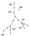
도 3을 다시 참고하면, 방법(300)은 304에서 기준 상태에서의 기준 모델로부터 노드 및 링키지의 낱낱의 강성적 기준 골격 트리를 생성하는 단계를 더 포함한다. 도 5는 3차원 용적 표현(400)에 기초한 골격 트리(420)를 나타내며 3차원 용적 표현(400)의 구조를 근사하기 위해 링키지(424)에 의해 상호연결된 복수의 노드(422)를 포함한다. 골격 트리(420)의 노드(402)는 중요한 굴곡부 또는 비틀림부의 지점 및/또는 해부구조 통로를 따르는 임의의 다른 지점에서의 해부구조 통로의 분기점에 위치될 수 있다. 노드는 일반적으로 해부구조 통로 내에 중심맞춤될 수 있지만, 대안 실시형태에서 통로 벽을 따라 또는 해부구조의 기준 구조와 관련한 다른 위치에 위치될 수 있다. 링키지(424)는 노드 사이에 연장되는 직선형 세그먼트이다. 링키지는 일반적으로 해부구조 통로 내에 중심맞춤되지만, 대안 실시형태에서 통로 벽을 따라 또는 해부구조의 기준 위치와 관련한 다른 위치에 위치될 수 있다.Referring back to FIG. 3 , the
도 3을 다시 참고하면, 방법(300)은 306에서 기준 기하학적 모델을 생성하는 단계를 더 포함할 수 있다. 일 실시형태에서, 도 6에 도시된 바와 같이, 기하학적 모델(450)은 해부구조 통로의 표면(내부 또는 외부)을 표현하는 복수의 삼각형(452)을 포함하는 다각형 메시 모델이다. 예를 들어, 해부학적 통로의 일부에 대한 메시 모델은 대략 130,000 개의 삼각형을 포함할 수 있다. 대안 실시형태에서, 다각형 메시 모델은 사변형 또는 다른 평평한, 볼록한, 또는 오목한 다각형을 포함할 수 있다. 메시 모델(450)의 각 정점은 골격 트리(420)의 노드(422) 중 하나에 결속될 수 있다. 따라서, 선택된 노드(422)에 결속된 메시 모델(450)의 각 정점은 또한 선택된 노드에 연결된 골격 링키지(424)에 결속된다.Referring again to FIG. 3 ,
도 3을 다시 참고하면, 방법(300)은 308에서 해부학적 움직임에 의한 해부구조 통로의 적어도 하나의 변형을 측정하는 단계를 더 포함한다. 환자 해부구조의 많은 영역은 통상적인 기능에 있어서 동적이다(예를 들어, 심장, 폐, 신장, 간, 혈관). 이 실시형태에서, 해부학적 움직임은 예를 들어 호흡 또는 심장 사이클에 의해 유발되는 폐의 순환적 해부학적 움직임일 수 있다. 변형은 기준 상태의 상태와 상이한 해부구조 사이클의 적어도 하나의 상태에서 측정된다. 예를 들어, 호흡 사이클에 대한 기준 상태가 완전 호기인 경우, 변형된 상태는 완전 흡기 상태에 있을 수 있다. 부가적으로 또는 대안적으로, 변형된 상태는 완전 흡기와 완전 호기 사이의 상태에서 발생할 수 있다. 해부구조 움직임이 심장 사이클로 인한 움직임을 포함하는 경우, 기준 상태는 예를 들어 조기 심확장 상태일 수 있고 변형된 상태는 심방 수축, 등용성 심실 수축, 심실 방출, 또는 등용성 심실 이완 상태 같은 심장 사이클의 다른 단계일 수 있다. 해부구조 통로의 변형은 앞서 설명된 영상화 기술 중 임의의 것을 사용한 수술 전 또는 수술 중 영상으로부터, 형상 센서 측정으로부터, 위치 센서 측정으로부터, 또는 움직임에 의한 변형을 측정하는 다른 공지된 방법에 의해 결정될 수 있다.Referring again to FIG. 3 , the
310에서, 방법(300)은 통로의 내부에 위치결정되는 중재 기구(예를 들어, 카테터(202))에 의해 적용되는 힘에 의한 해부구조 통로의 변형을 측정하는 단계를 포함한다. 중재 기구의 형상은 예를 들어 광학 형상 감지 섬유의 사용을 수반하는 기구 형상 감지를 위한 위에서 설명된 방법 중 임의의 것을 사용하여 감지될 수 있다.At 310 , the
312에서, 방법(300)은 해부학적 움직임 및 중재 기구의 영향에 의해 변형된 골격 트리를 생성하는 단계를 포함한다. 도 7은 해부구조 움직임에 의한 변형된 상태에서의 해부구조 통로의 골격 트리(460)를 나타낸다. 이 예시에서, 폐 통로는 완전 흡기의 변형된 상태에 있다. 변형된 골격(460)에서, 노드(422)의 위치 및 링키지(424)의 위치 및 배향은 변형된 상태의 영상화된 해부구조로부터 해부구조 통로와 정렬되도록 변형된다. 도 8은 해부구조 통로의 일부 내에서의 호기의 기준 상태에 있지만 중재 기구(472)에 의해 가해진 힘에 의한 변형된 상태에 있는 해부구조 통로의 골격 트리(470)를 나타낸다. 변형된 골격(470)에서, 노드(422)의 위치와 링키지(424)의 위치 및 배향은 중재 기구(472)에 대한 형상 측정에 기초하여 변형된다. 중재 기구(472)의 형상은 중재 기구가 위치되는 통로를 직접적으로 변형시킬 수 있지만 또한 통로를 연결하는 조직에 가해지는 힘에 의해 인접하는 통로를 간접적으로 변형시킬 수도 있다. 도 9는 해부구조 움직임(예를 들어, 완전 흡기, 도 7)과 중재 기구에 의해 가해진 힘(예를 들어, 도 8)의 조합에 의한 변형된 상태에서의 해부구조 통로의 골격 트리(480)를 나타낸다. 다양한 대안 실시형태에서, 다른 힘에 의해 유발되는 해부학적 통로의 변형이 복합 변형 골격 트리를 생성하기 위해 측정되고 사용될 수 있다.At 312 , the
도 3을 다시 참고하면, 방법(300)은 314에서 해부학적 움직임 및/또는 중재 기구 힘에 의한 측정된 변형을 기술하기 위해 변형 필드를 생성하는 단계를 더 포함한다. 예를 들어, 변형 필드는 기준 상태와 완전 변형 상태 사이의 일련의 중간 변형 상태에 있어서의 완전 호기 기준 상태로부터 완전 흡기 변형 상태까지의 해부학적 통로의 변형을 설명하는 3차원 필드 벡터 어레이를 포함할 수 있다. 도 10에 도시된 바와 같이, 변형 필드(490)는 골격 트리(480)로의 골격 트리(420)의 3차원 변형을 기술하는 3차원 필드 벡터 어레이를 포함할 수 있다.Referring again to FIG. 3 , the
도 3을 다시 참고하면, 방법(300)은 316에서 변형된 기하학적 모델을 생성하기 위해 기준 기하학적 모델에 변형 필드를 적용하는 단계를 더 포함한다. 일반적으로, 기준 메시 모델(450)의 각 정점에 대해, 변형 필드(490)의 내삽은 각 시간(t)에서 실행된다. 기준 메시 모델(450)로부터의 각 정점은 그 후 변형된 메시 모델(500)의 대응하는 정점으로 변환된다(도 11)Referring again to FIG. 3 , the
통상의 기술자에게 공지된 리니어 블렌드 스키닝(linear blend skinning)(LBS) 기술은 변형된 메시 모델의 생성에 사용될 수 있다. LBS 기술에 의해, 메시 모델(450)의 각 삼각형(452)의 각 정점은 정점의 변형에 책임이 있는 골격 트리(420)에 결속되어 있다. LBS 용어에서, 골격의 링키지는 "뼈"로 고려되며 "뼈 영향"을 제공한다. 각 정점에는 또한 정점에 영향을 주는 골격의 각 링키지에 대한 가중치(w i )가 할당될 수 있다. 가중 할당은 각 가중치에 대해 0≤w i ≤1 및 ∑w i =1이 되도록 된다. 가중치는 상이한 골격 자세를 생성한 후 메시가 변형될 때까지 가중치를 변화시킴으로써 실험적으로 구할 수 있다. 메시 모델(450)의 그 초기 자세로부터 각 정점(v)을 변형시키기 위해서, 골격 링키지에 의해 변형된 정점의 가중치 조합이 사용된다:Linear blend skinning (LBS) techniques known to those of ordinary skill in the art can be used to generate warped mesh models. With the LBS technique, each vertex of each
변형 식: 
여기서, N은 뼈 영향의 수이고, i는 골격의 링크이고, M은 골격 변형을 기술하는 변형 필드(490) 같은 절대 링크 변환 매트릭스이다.where N is the number of bone influences, i is the link of the skeleton, and M is an absolute link transformation matrix such as
가중을 결정하기 위한 예시적인 방법이 제공된다. 메시의 선택된 정점(v)에 대한 두 개의 링키지 영향(즉, 뼈 영향)에 의해, 변형 식에서 N=2이다. 정점(v)에 대한 w 1 및 w 2 를 결정하기 위해서, v에 대한 두 개의 최근접 링크가 선택된다. 제1 최근접 링크는 l 1 이고, 제2 최근접 링크는 l 2 이다. v와 l 1 (l 2 ) 사이의 거리는 v 와 l 1 (l 2 )의 지점 사이의 최단 유클리드 거리로서 규정되는 d v, l 1 (d v, l 2 )이다.An exemplary method for determining a weight is provided. With two linkage effects (i.e. bone effects) on the selected vertices v of the mesh, N=2 in the deformation equation. In order to determine the w 1 and w 2 for the vertex (v), the two nearest neighbor links to v is selected. The first nearest link is l 1 and the second nearest link is l 2 . v is the l 1 (l 2) d v , l 1 (d v, l 2) which is defined as the shortest Euclidian distance between the points v and the distance l 1 (l 2) between.
d v, l 1 및 d v, l 2 을 계산하기 위해서, 지점 P(정점(v)에서)와 세그먼트 S(즉, 골격의 링키지) 사이의 최단 거리가 P와 S의 끝점 중 하나 사이인지의 여부를 시험하기 위해 벡터의 내적이 적용된다. 이 시험은 다음과 같이 기술된다: d v, l 1 and d v, l 2 , to test whether the shortest distance between a point P (at the vertex v ) and a segment S (i.e., the linkage of the skeleton) is between one of the endpoints of P and S. The dot product of the vector is applied. This test is described as follows:

알고리즘은 또한 다음과 같이 표현될 수 있다.The algorithm can also be expressed as

따라서, w 1 및 w 2 는 d v, l 1 및 d v, l 2 의 표준화로서 계산될 수 있다:Thus, w 1 and w 2 can be calculated as the normalization of d v, l 1 and d v, l 2 :

따라서, 메시의 각 정점의 가중이 결정될 수 있고, 메시의 각 변형된 정점(v deformed )이 결정될 수 있다. 그래픽 처리 유닛(GPU)을 사용하는 메시 모델 변형의 실행이 도 14에 제공된다.Thus, the weight of each vertex of the mesh can be determined, and each deformed vertex v deformed of the mesh can be determined. An implementation of mesh model transformation using a graphics processing unit (GPU) is provided in FIG. 14 .
다시 도 3을 참고하면, 방법(300)은 318에서 도 12에 도시된 바와 같이 변형된 3차원 용적 표현(510)의 영상을 생성하기 위해 변형된 메시와 정렬되도록 기준 3차원 용적 표현(400)을 변형시키는 단계를 더 포함한다. Referring again to FIG. 3 , the
320에서, 중재 기구(472)의 영상과 함께 변형된 3차원 용적 표현(510) 또는 변형된 메시 모델(450)을 표시하는 복합 영상(520)(도 13)이 생성된다.At 320 , a composite image 520 ( FIG. 13 ) representing the warped three-
변형된 모델이 대략 실시간 표시 속도로 동적으로 표시될 수 있도록 변형된 메시 모델의 생성을 촉진시키기 위해, GPU를 사용하는 병행 계산 플랫폼 같은 소프트웨어 및/또는 하드웨어 기반 가속기가 사용될 수 있다. 이러한 계산 플랫폼에 의해, 기준 상태로부터 완전 변형 상태까지의 그리고 중간 변형 상태 모두를 포함하는 해부구조 통로의 변형된 영상이 표시될 수 있다. GPU는 1초당 대략 30개의 상이한 프레임의 속도로 그리고 몇몇 실시형태에서는 1초당 대략 50개의 상이한 프레임의 속도에서의 기준 및 변형 상태 영상의 표시를 가능하게 한다.Software and/or hardware-based accelerators, such as parallel computation platforms using GPUs, may be used to facilitate the creation of warped mesh models so that warped models can be displayed dynamically at approximately real-time display rates. With this computational platform, deformed images of the anatomical passageways can be displayed, both from the reference state to the fully deformed state and including all intermediate deformed states. The GPU enables display of reference and deformed state images at a rate of approximately 30 different frames per second and in some embodiments approximately 50 different frames per second.
도 14는 GPU(602)를 사용하는 메시 모델 변형[예를 들어, 방법(300)의 단계 316]의 방법(600)을 나타낸다. 604에서, 기준 상태의 메시 모델(예를 들어, 메시(450))은 중앙 처리 유닛(CPU)(606)에 제공된다. CPU(606)에서 동작하는 로더(608)가 메시 모델을 주 메모리(도시되지 않음)에 로드한다. 메모리로부터, 메시 모델은 GPU(602)에 전송된다.14 illustrates a
CPU에서 맵핑 단계(610)가 또한 실행된다. 도 15는 메시 공간(630)(예를 들어, 메시 모델(450)의 일부)과 3D 텍스처 메모리(612)에 저장되는 3D 텍스처 공간(632) 사이의 맵핑을 위한 맵핑 기술을 나타낸다. GPU(602)의 3D 텍스처 메모리(612)는 골격 트리의 각 노드 및 골격 노드 사이의 내삽 좌표에 대한 강체 변환을 저장한다. 3D 텍스처 메모리는 골격 노드에 대한 강체 변환을 저장하고 노드 사이의 좌표에 대한 변환을 내삽하는 신속하고 편리한 포맷을 제공한다. 내삽의 속도는 대략 실시간으로 골격 모델에 결속된 메시 모델의 변환 및 이동을 가능하게 한다. 골격의 많은 구성 노드에 걸친 강체 변환의 사용은 전체 메시 모델 공간에 걸친 비강체 변환에 근사한다. 3D 텍스처 메모리 공간(632)의 각 (T x, T y, T z ) 텍스처 공간 좌표는 메시 모델 공간(630)의 대응하는 메시 공간 좌표(M x, M y, M z )에 맵핑된다. (M x, M y, M z )에 대해서, 최근접 링크(l 1 (l 2 )) 및 가중치(w 1 (w 2 ))는 LBS 기술에 대해 위에서 기술된 것과 같이 결정된다. (M x, M y, M z )가 골격의 임의의 링크로부터 과도하게 멀리 있으면, w 1 =w 2 =0 이다. 메모리 공간을 절약하기 위해서, 맵핑 단계(610)의 출력물은 w 1 ≠0인 경우 그리고 w 1 ≠0인 경우에만 5개의 열을 갖는 맵핑 테이블(아래 도시됨)이다.A
![]()
![]()
맵핑 테이블은 각 변형에 대해 오직 한번 계산되면 될 수 있다. 맵핑 테이블은 GPU(602)로 이동된다.The mapping table can only be computed once for each transformation. The mapping table is moved to
각 시간 t에 대해, 비강체 변환(614)이 GPU(602)로 이동된다. 비강체 변환 알고리즘(614)은 노드가 변형된 골격 트리(480)에 기초하여 어떻게 이동되어야 하는지를 기술하기 위해 골격 트리(420)의 각 노드에 대한 강체 변형치를 계산하기 위해 사용된다. 616에서, 비강체 변환(614)은 골격 트리의 각 노드에 대한 변환을 계산하기 위해 GPU(602)에 의해 사용된다. 생성된 맵핑 테이블에 기초하여, 완전 변형 필드가 3D 텍스처 공간(632)의 각 내삽 좌표에 대해 변환된 골격 트리 노드로부터 전개된다. 3D 텍스처 메모리(612)는 3D 텍스처 공간(632)의 각 좌표에 대한 변환을 저장한다. 3D 텍스처 메모리(612)의 필드는 GPU에 의해 동시에 충전된다. GPU의 별도의 스레드(즉, 독립적으로 관리된 프로그래밍된 명령의 작은 시퀀스)가 3D 텍스처 메모리의 각 좌표에 대해 위에서 제공된 변형 식을 사용하여 변형 값을 계산하기 위해 작업한다. GPU의 3D 텍스처 메모리는 두 가지 목표의 역할을 한다. 첫 번째로, 텍스처의 치수는 모델 공간보다 훨씬 더 작다. 예를 들어, 3D 텍스처 메모리는 128 × 128 × 128 복셀 어레이를 사용할 수 있고, 모델 공간은 1024 × 1024 × 1024 복셀 어레이를 사용할 수 있다. 두 번째로, 선형 내삽과 함께 GPU의 3D 텍스처 메모리의 값을 가져오는 것은 매우 신속하다.For each time t , the
618에서, 메시 모델(450)의 각 정점에 작용하는 하나의 스레드에 의해, 스레드는 초기 메시 모델(450)의 정점의 위치에 대응하고 그것을 변형된 정점으로 변환하는 3D 텍스처 메모리(612)로부터 값을 가져온다(맵핑 테이블을 사용하여). 620에서, 기준 상태 정점의 각각에 대해 생성된 변형된 정점에 의해, 변형된 메시 모델이 생성되고 표시된다. 변형된 메시 모델의 표시는 환자 해부구조의 거의 실시간적인 변형에 대응하는 높은 표시 속도로 갱신되는 변형 메시 모델의 표시에 의해 동적으로 표현될 수 있다. 예를 들어, 표시의 속도는 1초당 대략 30 이상의 프레임일 수 있다. 따라서, 환자 해부구조를 통해 중재 기구를 항행시키는 임상의사는 환자 해부구조의 현재 변형 상태의 현재 영상을 제공받는다.At 618 , with one thread acting on each vertex of the
본 발명의 실시형태의 하나 이상의 요소는 제어 시스템(112) 같은 컴퓨터 시스템의 프로세서에서 실행되는 소프트웨어에서 실행될 수 있다. 소프트웨어에서 실행될 때, 본 발명의 실시형태의 요소는 본질적으로 필요한 임무를 수행하는 코드 세그먼트이다. 프로그램 또는 코드 세그먼트는, 전송 매체 또는 통신 링크를 통해 반송파로 구현되는 컴퓨터 데이터 신호에 의해 다운로드될 수 있었던 프로세서 판독가능 저장 매체 또는 장치에 저장될 수 있다. 프로세서 판독가능 저장 장치는 광학 매체, 반도체 매체, 및 자기 매체를 포함하는 정보를 저장할 수 있는 임의의 매체를 포함할 수 있다. 프로세서 판독가능 저장 정치 예는 전자 회로, 반도체 디바이스, 반도체 메모리 디바이스, 리드 온리 메모리(ROM), 플래시 메모리, 소거할 수 있는 프로그램 가능한 리드 온리 메모리(EPROM), 플로피 디스켓, CD-ROM, 광학 디스크, 하드 디스크 또는 다른 저장 디바이스를 포함하고, 코드 세그먼트는 인터넷, 인트라넷, 등의 컴퓨터 네트워크를 통해 다운로드 될 수 있다.One or more elements of an embodiment of the invention may be implemented in software running on a processor of a computer system, such as
제시된 프로세스 및 디스플레이는 본질적으로 임의의 특정 컴퓨터 또는 다른 장치와 관련될 수 없다는 점에 유의한다. 다양한 이러한 시스템을 위한 필요한 구조는 청구항의 요소로서 명확할 것이다. 또한, 본 발명의 실시형태는 임의의 특정 프로그래밍 언어를 참고하여 설명되지 않는다. 여기에 설명된 바와 같은 본 발명의 교시를 실행하기 위해 다양한 프로그래밍 언어가 사용될 수 있다는 것이 이해될 것이다.It should be noted that the presented processes and displays may not necessarily be related to any particular computer or other device. The necessary structure for a variety of such systems will be apparent as elements of the claims. In addition, embodiments of the present invention are not described with reference to any particular programming language. It will be understood that a variety of programming languages may be used to practice the teachings of the present invention as described herein.
본 발명의 소정의 예시적인 실시형태가 첨부 도면에 개시되고 도시되었으나, 이러한 실시형태는 광범위한 발명의 예시일 뿐이고 광범위한 발명에 대한 제약이 아니며, 본 발명의 실시형태는 도시되고 개시된 특성 구성 및 배열로 제한되지 않는데, 이는 통상의 기술자에게 다양한 다른 변형예가 발생할 수 있기 때문이라는 점을 이해해야 한다.While certain exemplary embodiments of the present invention have been disclosed and illustrated in the accompanying drawings, these embodiments are merely illustrative of the broad invention and not a limitation thereof, and the embodiments of the invention are not limited to the features, configurations and arrangements shown and disclosed. It is to be understood that this is not limiting, as various other modifications may occur to those skilled in the art.
Claims (15)
프로세서에 의해 기준 상태의 분기형 해부학적 구성물의 기준 3차원 모델을 수신하는 단계와,
프로세서에 의해 기준 3차원 모델 상의 지점에 대해 3차원 변형 필드를 내삽하는 단계와, 프로세서에 의해 기준 3차원 모델 상의 지점을 분기형 해부학적 구성물의 변형된 상태의 변형된 3차원 모델 상의 지점으로 변환하는 단계에 의해 분기형 해부학적 구성물의 변형된 상태의 변형된 3차원 모델을 생성하도록, 프로세서에 의해 3차원 변형 필드를 기준 3차원 모델에 적용하는 단계와,
프로세서에 의해 분기형 해부학적 구성물의 변형된 상태의 변형된 3차원 모델의 영상을 동적으로 표시하는 단계와,
프로세서에 의해 생성되는 분기형 해부학적 구성물의 기준 상태에 대한 기준 골격 트리와, 프로세서에 의해 생성되는 분기형 해부학적 구성물의 변형된 상태에 대한 변형된 골격 트리에 기초하여 기준 상태에서 변형된 상태로 변형을 설명하는 3차원 필드 벡터 어레이를 프로세서에 의해 생성하는 단계에 의해, 프로세서에 의해 3차원 변형 필드를 생성하는 단계를 포함하고,
3차원 변형 필드는 3차원 필드 벡터 어레이를 포함하는,
처리 시스템의 조작 방법.A method of operating a processing system comprising a processor,
receiving, by the processor, a reference three-dimensional model of the bifurcated anatomical construct in a reference state;
interpolating, by a processor, a three-dimensional deformation field with respect to a point on the reference three-dimensional model; and transforming, by the processor, a point on the reference three-dimensional model into a point on the deformed three-dimensional model of the deformed state of the bifurcated anatomical construct. applying the three-dimensional deformation field to the reference three-dimensional model by the processor to produce a deformed three-dimensional model of the deformed state of the bifurcated anatomical construct by the step of:
Dynamically displaying an image of the deformed three-dimensional model of the deformed state of the bifurcated anatomical construct by the processor;
from the reference state to the transformed state based on the reference skeletal tree for the reference state of the bifurcated anatomical construct generated by the processor and the modified skeletal tree for the deformed state of the bifurcated anatomical construct generated by the processor. generating, by the processor, a three-dimensional field vector array describing the deformation, the three-dimensional deformation field being generated by the processor;
The three-dimensional transformation field comprises an array of three-dimensional field vectors;
How to operate the processing system.
분기형 해부학적 구성물의 변형된 상태는 적어도 부분적으로 주기적 해부학적 움직임에 의해 유발되는,
처리 시스템의 조작 방법.According to claim 1,
wherein the deformed state of the bifurcated anatomical construct is caused, at least in part, by periodic anatomical movement;
How to operate the processing system.
분기형 해부학적 구성물의 변형된 상태는 적어도 부분적으로 분기형 해부학적 구성물 내에 위치결정되는 중재 기구에 의해 유발되는,
처리 시스템의 조작 방법.According to claim 1,
wherein the deformed state of the bifurcated anatomical construct is caused at least in part by an interventional instrument positioned within the bifurcated anatomical construct;
How to operate the processing system.
3차원 변형 필드를 기준 3차원 모델에 적용하는 단계는 그래픽 처리 유닛에서 실행되는,
처리 시스템의 조작 방법.According to claim 1,
wherein the step of applying the three-dimensional deformation field to the reference three-dimensional model is executed in a graphics processing unit;
How to operate the processing system.
프로세서에 의해 분기형 해부학적 구성물 내에 위치결정되는 중재 기구의 영상 및 분기형 해부학적 구성물의 변형된 상태의 변형된 3차원 모델의 영상을 포함하는 복합 영상을 표시하는 단계를 더 포함하는,
처리 시스템의 조작 방법.5. The method according to any one of claims 1 to 4,
further comprising displaying, by the processor, a composite image comprising an image of the interventional instrument positioned within the bifurcated anatomical construct and an image of the deformed three-dimensional model of the deformed state of the bifurcated anatomical construct;
How to operate the processing system.
기준 3차원 모델을 수신하는 단계는 3차원 메시 모델을 수신하는 단계를 포함하는,
처리 시스템의 조작 방법.5. The method according to any one of claims 1 to 4,
receiving the reference three-dimensional model comprises receiving a three-dimensional mesh model;
How to operate the processing system.
변형된 3차원 모델은 변형된 3차원 메시 모델을 포함하는,
처리 시스템의 조작 방법.5. The method according to any one of claims 1 to 4,
The deformed three-dimensional model comprises a deformed three-dimensional mesh model,
How to operate the processing system.
프로세서에 의해 분기형 해부학적 구성물의 변형된 상태의 변형된 3차원 모델을 생성하기 위해 3차원 변형 필드를 기준 3차원 모델에 적용하는 단계는, 프로세서에 의해 변형된 정점 세트를 생성하는 단계를 포함하고,
변형된 3차원 메시 모델은 변형된 정점 세트를 포함하는,
처리 시스템의 조작 방법.8. The method of claim 7,
applying, by the processor, the three-dimensional deformation field to the reference three-dimensional model to generate a deformed three-dimensional model of a deformed state of the bifurcated anatomical construct, comprising generating, by the processor, a set of deformed vertices do,
A warped three-dimensional mesh model comprising a set of warped vertices,
How to operate the processing system.
프로세서와,
컴퓨터 판독가능 명령이 저장되어 있는 메모리를 포함하고,
컴퓨터 판독가능 명령은 프로세서에 의해 실행될 때 처리 시스템이,
기준 상태의 분기형 해부학적 구성물의 기준 3차원 모델을 수신하게 하고,
기준 3차원 모델 상의 지점에 대해 3차원 변형 필드를 내삽하는 단계와, 기준 3차원 모델 상의 지점을 분기형 해부학적 구성물의 변형된 상태의 변형된 3차원 모델 상의 지점으로 변환하는 단계에 의해 분기형 해부학적 구성물의 변형된 상태의 변형된 3차원 모델을 생성하도록 3차원 변형 필드를 기준 3차원 모델에 적용하게 하고,
분기형 해부학적 구성물의 변형된 상태의 변형된 3차원 모델의 영상을 동적으로 표시하게 하고,
프로세서에 의해 생성되는 분기형 해부학적 구성물의 기준 상태에 대한 기준 골격 트리와, 프로세서에 의해 생성되는 분기형 해부학적 구성물의 변형된 상태에 대한 변형된 골격 트리에 기초하여 프로세서에 의해 기준 상태에서 변형된 상태로 변형을 설명하는 3차원 필드 벡터 어레이를 생성하는 단계에 의해, 3차원 변형 필드를 생성하게 하고,
3차원 변형 필드는 3차원 필드 벡터 어레이를 포함하는,
처리 시스템.processing system,
processor and
a memory having computer readable instructions stored thereon;
The computer readable instructions, when executed by the processor, cause the processing system to:
receive a reference three-dimensional model of the bifurcated anatomical construct in a reference state;
bifurcated by interpolating a three-dimensional deformation field with respect to a point on the reference three-dimensional model, and transforming the point on the reference three-dimensional model into a point on the deformed three-dimensional model of the deformed state of the bifurcated anatomical construct. apply the three-dimensional deformation field to the reference three-dimensional model to generate a deformed three-dimensional model of the deformed state of the anatomical construct;
to dynamically display the image of the deformed three-dimensional model of the deformed state of the bifurcated anatomical construct,
Deformation from the reference state by the processor based on the reference skeletal tree for the reference state of the branched anatomical construct generated by the processor and the modified skeletal tree for the deformed state of the branched anatomical construct generated by the processor generating a three-dimensional deformation field by generating a three-dimensional field vector array describing the deformation in the
The three-dimensional transformation field comprises an array of three-dimensional field vectors;
processing system.
분기형 해부학적 구성물의 변형된 상태는 적어도 부분적으로 주기적인 해부학적 움직임에 의해 유발되는,
처리 시스템.10. The method of claim 9,
wherein the deformed state of the bifurcated anatomical construct is caused, at least in part, by periodic anatomical movements;
processing system.
분기형 해부학적 구성물의 변형된 상태는 적어도 부분적으로 분기형 해부학적 구성물 내에 위치결정되는 중재 기구에 의해 유발되는,
처리 시스템.10. The method of claim 9,
wherein the deformed state of the bifurcated anatomical construct is caused at least in part by an interventional instrument positioned within the bifurcated anatomical construct;
processing system.
분기형 해부학적 구성물 내에 위치결정되는 중재 기구의 영상 및 분기형 해부학적 구성물의 변형된 상태의 변형된 3차원 모델의 영상을 포함하는 복합 영상을 표시하게 하는 것을 더 포함하는,
처리 시스템.12. The method according to any one of claims 9 to 11,
further comprising causing displaying a composite image comprising an image of an interventional instrument positioned within the bifurcated anatomical construct and an image of the deformed three-dimensional model of the deformed state of the bifurcated anatomical construct;
processing system.
기준 3차원 모델을 수신하게 하는 것은 3차원 메시 모델을 수신하게 하는 것을 포함하는,
처리 시스템.12. The method according to any one of claims 9 to 11,
receiving the reference three-dimensional model comprises receiving a three-dimensional mesh model;
processing system.
변형된 3차원 모델은 변형된 3차원 메시 모델을 포함하는,
처리 시스템.12. The method according to any one of claims 9 to 11,
The deformed three-dimensional model comprises a deformed three-dimensional mesh model,
processing system.
프로세서에 의해 분기형 해부학적 구성물의 변형된 상태의 변형된 3차원 모델을 생성하기 위해 3차원 변형 필드를 기준 3차원 모델에 적용하게 하는 것은, 프로세서에 의해 변형된 정점 세트를 생성하게 하는 것을 포함하고,
변형된 3차원 메시 모델은 변형된 정점 세트를 포함하는,
처리 시스템의 조작 방법.15. The method of claim 14,
Applying, by the processor, a three-dimensional deformation field to the reference three-dimensional model to generate a deformed three-dimensional model of a deformed state of the bifurcated anatomical construct comprises causing, by the processor, generating a set of deformed vertices. do,
A warped three-dimensional mesh model comprising a set of warped vertices,
How to operate the processing system.
Applications Claiming Priority (4)
| Application Number | Priority Date | Filing Date | Title |
|---|---|---|---|
| US201461935547P | 2014-02-04 | 2014-02-04 | |
| US61/935,547 | 2014-02-04 | ||
| KR1020167024042A KR20160118295A (en) | 2014-02-04 | 2015-02-03 | Systems and methods for non-rigid deformation of tissue for virtual navigation of interventional tools |
| PCT/US2015/014226 WO2015119935A1 (en) | 2014-02-04 | 2015-02-03 | Systems and methods for non-rigid deformation of tissue for virtual navigation of interventional tools |
Related Parent Applications (1)
| Application Number | Title | Priority Date | Filing Date |
|---|---|---|---|
| KR1020167024042A Division KR20160118295A (en) | 2014-02-04 | 2015-02-03 | Systems and methods for non-rigid deformation of tissue for virtual navigation of interventional tools |
Publications (1)
| Publication Number | Publication Date |
|---|---|
| KR20210156301A true KR20210156301A (en) | 2021-12-24 |
Family
ID=53778370
Family Applications (2)
| Application Number | Title | Priority Date | Filing Date |
|---|---|---|---|
| KR1020167024042A KR20160118295A (en) | 2014-02-04 | 2015-02-03 | Systems and methods for non-rigid deformation of tissue for virtual navigation of interventional tools |
| KR1020217040900A KR20210156301A (en) | 2014-02-04 | 2015-02-03 | Systems and methods for non-rigid deformation of tissue for virtual navigation of interventional tools |
Family Applications Before (1)
| Application Number | Title | Priority Date | Filing Date |
|---|---|---|---|
| KR1020167024042A KR20160118295A (en) | 2014-02-04 | 2015-02-03 | Systems and methods for non-rigid deformation of tissue for virtual navigation of interventional tools |
Country Status (6)
| Country | Link |
|---|---|
| US (6) | US10314656B2 (en) |
| EP (2) | EP3979210A1 (en) |
| JP (2) | JP2017511712A (en) |
| KR (2) | KR20160118295A (en) |
| CN (1) | CN106170265B (en) |
| WO (1) | WO2015119935A1 (en) |
Families Citing this family (103)
| Publication number | Priority date | Publication date | Assignee | Title |
|---|---|---|---|---|
| US8218847B2 (en) | 2008-06-06 | 2012-07-10 | Superdimension, Ltd. | Hybrid registration method |
| US8672837B2 (en) | 2010-06-24 | 2014-03-18 | Hansen Medical, Inc. | Methods and devices for controlling a shapeable medical device |
| US9057600B2 (en) | 2013-03-13 | 2015-06-16 | Hansen Medical, Inc. | Reducing incremental measurement sensor error |
| US9271663B2 (en) | 2013-03-15 | 2016-03-01 | Hansen Medical, Inc. | Flexible instrument localization from both remote and elongation sensors |
| US9629595B2 (en) | 2013-03-15 | 2017-04-25 | Hansen Medical, Inc. | Systems and methods for localizing, tracking and/or controlling medical instruments |
| US9014851B2 (en) | 2013-03-15 | 2015-04-21 | Hansen Medical, Inc. | Systems and methods for tracking robotically controlled medical instruments |
| US11020016B2 (en) | 2013-05-30 | 2021-06-01 | Auris Health, Inc. | System and method for displaying anatomy and devices on a movable display |
| KR20160118295A (en) | 2014-02-04 | 2016-10-11 | 인튜어티브 서지컬 오퍼레이션즈 인코포레이티드 | Systems and methods for non-rigid deformation of tissue for virtual navigation of interventional tools |
| US10772684B2 (en) * | 2014-02-11 | 2020-09-15 | Koninklijke Philips N.V. | Spatial visualization of internal mammary artery during minimally invasive bypass surgery |
| EP2923669B1 (en) | 2014-03-24 | 2017-06-28 | Hansen Medical, Inc. | Systems and devices for catheter driving instinctiveness |
| US9633431B2 (en) | 2014-07-02 | 2017-04-25 | Covidien Lp | Fluoroscopic pose estimation |
| US9603668B2 (en) | 2014-07-02 | 2017-03-28 | Covidien Lp | Dynamic 3D lung map view for tool navigation inside the lung |
| US10373719B2 (en) | 2014-09-10 | 2019-08-06 | Intuitive Surgical Operations, Inc. | Systems and methods for pre-operative modeling |
| EP3200718A4 (en) | 2014-09-30 | 2018-04-25 | Auris Surgical Robotics, Inc | Configurable robotic surgical system with virtual rail and flexible endoscope |
| US10314463B2 (en) | 2014-10-24 | 2019-06-11 | Auris Health, Inc. | Automated endoscope calibration |
| US9986983B2 (en) | 2014-10-31 | 2018-06-05 | Covidien Lp | Computed tomography enhanced fluoroscopic system, device, and method of utilizing the same |
| US10716525B2 (en) | 2015-08-06 | 2020-07-21 | Covidien Lp | System and method for navigating to target and performing procedure on target utilizing fluoroscopic-based local three dimensional volume reconstruction |
| US10674982B2 (en) | 2015-08-06 | 2020-06-09 | Covidien Lp | System and method for local three dimensional volume reconstruction using a standard fluoroscope |
| US10702226B2 (en) | 2015-08-06 | 2020-07-07 | Covidien Lp | System and method for local three dimensional volume reconstruction using a standard fluoroscope |
| AU2016323982A1 (en) | 2015-09-18 | 2018-04-12 | Auris Health, Inc. | Navigation of tubular networks |
| EP3352648B1 (en) | 2015-09-26 | 2022-10-26 | Boston Scientific Scimed Inc. | Multiple rhythm template monitoring |
| US10405766B2 (en) | 2015-09-26 | 2019-09-10 | Boston Scientific Scimed, Inc. | Method of exploring or mapping internal cardiac structures |
| EP3353753A1 (en) * | 2015-09-26 | 2018-08-01 | Boston Scientific Scimed Inc. | Systems and methods for anatomical shell editing |
| US10143526B2 (en) | 2015-11-30 | 2018-12-04 | Auris Health, Inc. | Robot-assisted driving systems and methods |
| JP6701232B2 (en) * | 2016-01-08 | 2020-05-27 | オリンパス株式会社 | Manipulator system and its driving method |
| US9898858B2 (en) * | 2016-05-18 | 2018-02-20 | Siemens Healthcare Gmbh | Human body representation with non-rigid parts in an imaging system |
| US9931025B1 (en) | 2016-09-30 | 2018-04-03 | Auris Surgical Robotics, Inc. | Automated calibration of endoscopes with pull wires |
| WO2018122946A1 (en) | 2016-12-27 | 2018-07-05 | オリンパス株式会社 | Shape acquisition method and control method for medical manipulator |
| US10244926B2 (en) | 2016-12-28 | 2019-04-02 | Auris Health, Inc. | Detecting endolumenal buckling of flexible instruments |
| US11793579B2 (en) | 2017-02-22 | 2023-10-24 | Covidien Lp | Integration of multiple data sources for localization and navigation |
| KR102558061B1 (en) | 2017-03-31 | 2023-07-25 | 아우리스 헬스, 인코포레이티드 | A robotic system for navigating the intraluminal tissue network that compensates for physiological noise |
| EP3613057A4 (en) * | 2017-04-18 | 2021-04-21 | Intuitive Surgical Operations, Inc. | Graphical user interface for planning a procedure |
| CN110831498B (en) | 2017-05-12 | 2022-08-12 | 奥瑞斯健康公司 | Biopsy device and system |
| US10022192B1 (en) | 2017-06-23 | 2018-07-17 | Auris Health, Inc. | Automatically-initialized robotic systems for navigation of luminal networks |
| WO2019005872A1 (en) | 2017-06-28 | 2019-01-03 | Auris Health, Inc. | Instrument insertion compensation |
| US10699448B2 (en) | 2017-06-29 | 2020-06-30 | Covidien Lp | System and method for identifying, marking and navigating to a target using real time two dimensional fluoroscopic data |
| US10426559B2 (en) | 2017-06-30 | 2019-10-01 | Auris Health, Inc. | Systems and methods for medical instrument compression compensation |
| CN111163697B (en) | 2017-10-10 | 2023-10-03 | 柯惠有限合伙公司 | System and method for identifying and marking targets in fluorescent three-dimensional reconstruction |
| US10145747B1 (en) | 2017-10-10 | 2018-12-04 | Auris Health, Inc. | Detection of undesirable forces on a surgical robotic arm |
| US10555778B2 (en) | 2017-10-13 | 2020-02-11 | Auris Health, Inc. | Image-based branch detection and mapping for navigation |
| US11058493B2 (en) | 2017-10-13 | 2021-07-13 | Auris Health, Inc. | Robotic system configured for navigation path tracing |
| JP7362610B2 (en) | 2017-12-06 | 2023-10-17 | オーリス ヘルス インコーポレイテッド | System and method for correcting uncommanded instrument rotation |
| AU2018384820A1 (en) | 2017-12-14 | 2020-05-21 | Auris Health, Inc. | System and method for estimating instrument location |
| KR20200101334A (en) | 2017-12-18 | 2020-08-27 | 아우리스 헬스, 인코포레이티드 | Method and system for tracking and navigation of instruments in the luminal network |
| JP6999824B2 (en) | 2018-01-17 | 2022-01-19 | オーリス ヘルス インコーポレイテッド | Surgical platform with adjustable arm support |
| US10893842B2 (en) | 2018-02-08 | 2021-01-19 | Covidien Lp | System and method for pose estimation of an imaging device and for determining the location of a medical device with respect to a target |
| US10905498B2 (en) | 2018-02-08 | 2021-02-02 | Covidien Lp | System and method for catheter detection in fluoroscopic images and updating displayed position of catheter |
| US10930064B2 (en) | 2018-02-08 | 2021-02-23 | Covidien Lp | Imaging reconstruction system and method |
| KR102014355B1 (en) * | 2018-02-20 | 2019-08-26 | (주)휴톰 | Method and apparatus for calculating location information of surgical device |
| WO2019164271A1 (en) * | 2018-02-20 | 2019-08-29 | (주)휴톰 | Virtual body model generation method and device |
| KR102500422B1 (en) | 2018-03-28 | 2023-02-20 | 아우리스 헬스, 인코포레이티드 | System and method for displaying the estimated position of an instrument |
| JP7214747B2 (en) | 2018-03-28 | 2023-01-30 | オーリス ヘルス インコーポレイテッド | System and method for position sensor alignment |
| EP3801190A4 (en) | 2018-05-30 | 2022-03-02 | Auris Health, Inc. | Systems and methods for location sensor-based branch prediction |
| EP3801280A4 (en) | 2018-05-31 | 2022-03-09 | Auris Health, Inc. | Robotic systems and methods for navigation of luminal network that detect physiological noise |
| MX2020012898A (en) | 2018-05-31 | 2021-02-26 | Auris Health Inc | Path-based navigation of tubular networks. |
| KR102455671B1 (en) | 2018-05-31 | 2022-10-20 | 아우리스 헬스, 인코포레이티드 | Image-Based Airway Analysis and Mapping |
| US11071591B2 (en) | 2018-07-26 | 2021-07-27 | Covidien Lp | Modeling a collapsed lung using CT data |
| US11705238B2 (en) | 2018-07-26 | 2023-07-18 | Covidien Lp | Systems and methods for providing assistance during surgery |
| US10881280B2 (en) | 2018-08-24 | 2021-01-05 | Auris Health, Inc. | Manually and robotically controllable medical instruments |
| JP7427654B2 (en) | 2018-09-17 | 2024-02-05 | オーリス ヘルス インコーポレイテッド | Systems and methods for performing associated medical procedures |
| US11944388B2 (en) | 2018-09-28 | 2024-04-02 | Covidien Lp | Systems and methods for magnetic interference correction |
| EP3856064A4 (en) | 2018-09-28 | 2022-06-29 | Auris Health, Inc. | Systems and methods for docking medical instruments |
| US11877806B2 (en) | 2018-12-06 | 2024-01-23 | Covidien Lp | Deformable registration of computer-generated airway models to airway trees |
| US11045075B2 (en) | 2018-12-10 | 2021-06-29 | Covidien Lp | System and method for generating a three-dimensional model of a surgical site |
| US11801113B2 (en) | 2018-12-13 | 2023-10-31 | Covidien Lp | Thoracic imaging, distance measuring, and notification system and method |
| US11617493B2 (en) | 2018-12-13 | 2023-04-04 | Covidien Lp | Thoracic imaging, distance measuring, surgical awareness, and notification system and method |
| EP3866718A4 (en) | 2018-12-20 | 2022-07-20 | Auris Health, Inc. | Systems and methods for robotic arm alignment and docking |
| JP2022515835A (en) | 2018-12-28 | 2022-02-22 | オーリス ヘルス インコーポレイテッド | Percutaneous sheath for robotic medical systems and methods |
| US11357593B2 (en) | 2019-01-10 | 2022-06-14 | Covidien Lp | Endoscopic imaging with augmented parallax |
| US11625825B2 (en) | 2019-01-30 | 2023-04-11 | Covidien Lp | Method for displaying tumor location within endoscopic images |
| US11564751B2 (en) | 2019-02-01 | 2023-01-31 | Covidien Lp | Systems and methods for visualizing navigation of medical devices relative to targets |
| US11925333B2 (en) | 2019-02-01 | 2024-03-12 | Covidien Lp | System for fluoroscopic tracking of a catheter to update the relative position of a target and the catheter in a 3D model of a luminal network |
| US11744643B2 (en) | 2019-02-04 | 2023-09-05 | Covidien Lp | Systems and methods facilitating pre-operative prediction of post-operative tissue function |
| WO2020163076A1 (en) | 2019-02-08 | 2020-08-13 | Auris Health, Inc. | Robotically controlled clot manipulation and removal |
| US11819285B2 (en) | 2019-04-05 | 2023-11-21 | Covidien Lp | Magnetic interference detection systems and methods |
| US11369448B2 (en) | 2019-04-08 | 2022-06-28 | Auris Health, Inc. | Systems, methods, and workflows for concomitant procedures |
| US20200375665A1 (en) * | 2019-05-31 | 2020-12-03 | Canon U.S.A., Inc. | Medical continuum robot and methods thereof |
| KR20220050151A (en) | 2019-08-15 | 2022-04-22 | 아우리스 헬스, 인코포레이티드 | Medical device having multiple bend sections |
| US11269173B2 (en) | 2019-08-19 | 2022-03-08 | Covidien Lp | Systems and methods for displaying medical video images and/or medical 3D models |
| WO2021038495A1 (en) | 2019-08-30 | 2021-03-04 | Auris Health, Inc. | Instrument image reliability systems and methods |
| WO2021038469A1 (en) * | 2019-08-30 | 2021-03-04 | Auris Health, Inc. | Systems and methods for weight-based registration of location sensors |
| US11931111B2 (en) | 2019-09-09 | 2024-03-19 | Covidien Lp | Systems and methods for providing surgical guidance |
| US11864935B2 (en) | 2019-09-09 | 2024-01-09 | Covidien Lp | Systems and methods for pose estimation of a fluoroscopic imaging device and for three-dimensional imaging of body structures |
| CN114630618A (en) | 2019-09-09 | 2022-06-14 | 马格尼司帝有限公司 | Method and apparatus for authenticating three-dimensional objects |
| CN114375182A (en) | 2019-09-10 | 2022-04-19 | 奥瑞斯健康公司 | System and method for kinematic optimization using shared robot degrees of freedom |
| US11627924B2 (en) | 2019-09-24 | 2023-04-18 | Covidien Lp | Systems and methods for image-guided navigation of percutaneously-inserted devices |
| EP4034349A1 (en) | 2019-09-26 | 2022-08-03 | Auris Health, Inc. | Systems and methods for collision detection and avoidance |
| KR20220123087A (en) | 2019-12-31 | 2022-09-05 | 아우리스 헬스, 인코포레이티드 | Alignment interface for transdermal access |
| EP4084721A4 (en) | 2019-12-31 | 2024-01-03 | Auris Health Inc | Anatomical feature identification and targeting |
| KR20220123076A (en) | 2019-12-31 | 2022-09-05 | 아우리스 헬스, 인코포레이티드 | Alignment Techniques for Transdermal Access |
| US11380060B2 (en) | 2020-01-24 | 2022-07-05 | Covidien Lp | System and method for linking a segmentation graph to volumetric data |
| US11847730B2 (en) | 2020-01-24 | 2023-12-19 | Covidien Lp | Orientation detection in fluoroscopic images |
| CN111627092B (en) * | 2020-05-07 | 2021-03-09 | 江苏原力数字科技股份有限公司 | Method for constructing high-strength bending constraint from topological relation |
| CN113926050A (en) * | 2020-06-29 | 2022-01-14 | 巴德阿克塞斯系统股份有限公司 | Automatic dimensional reference system for optical fibers |
| US11839969B2 (en) | 2020-06-29 | 2023-12-12 | Auris Health, Inc. | Systems and methods for detecting contact between a link and an external object |
| US11357586B2 (en) | 2020-06-30 | 2022-06-14 | Auris Health, Inc. | Systems and methods for saturated robotic movement |
| WO2022003493A1 (en) | 2020-06-30 | 2022-01-06 | Auris Health, Inc. | Robotic medical system with collision proximity indicators |
| US11950950B2 (en) | 2020-07-24 | 2024-04-09 | Covidien Lp | Zoom detection and fluoroscope movement detection for target overlay |
| US20240041535A1 (en) * | 2020-12-10 | 2024-02-08 | Magnisity Ltd. | Dynamic deformation tracking for navigational bronchoscopy |
| US11475632B1 (en) * | 2020-12-17 | 2022-10-18 | Neucures Inc | System and method for electro-anatomical mapping (EAM) based on a surface mesh |
| US20230013884A1 (en) * | 2021-07-14 | 2023-01-19 | Cilag Gmbh International | Endoscope with synthetic aperture multispectral camera array |
| WO2023037367A1 (en) * | 2021-09-09 | 2023-03-16 | Magnisity Ltd. | Self-steering endoluminal device using a dynamic deformable luminal map |
| WO2023218468A1 (en) * | 2022-05-12 | 2023-11-16 | Magnisity Ltd. | Curve inductive sensor |
Family Cites Families (30)
| Publication number | Priority date | Publication date | Assignee | Title |
|---|---|---|---|---|
| JP3510025B2 (en) | 1995-11-10 | 2004-03-22 | ジーイー横河メディカルシステム株式会社 | Ultrasound imaging device |
| WO1998036236A1 (en) | 1997-02-13 | 1998-08-20 | Super Dimension Ltd. | Six-degree tracking system |
| GB9713018D0 (en) | 1997-06-20 | 1997-08-27 | Secr Defence | Optical fibre bend sensor |
| JP2000182076A (en) * | 1998-12-16 | 2000-06-30 | Sony Corp | Data processor, data processing method and provision medium |
| EP1691666B1 (en) | 2003-12-12 | 2012-05-30 | University of Washington | Catheterscope 3d guidance and interface system |
| ATE482664T1 (en) | 2004-01-20 | 2010-10-15 | Koninkl Philips Electronics Nv | DEVICE AND METHOD FOR NAVIGATING A CATHETER |
| US7450743B2 (en) | 2004-01-21 | 2008-11-11 | Siemens Medical Solutions Usa, Inc. | Method and system of affine registration of inter-operative two dimensional images and pre-operative three dimensional images |
| US20060013523A1 (en) | 2004-07-16 | 2006-01-19 | Luna Innovations Incorporated | Fiber optic position and shape sensing device and method relating thereto |
| US7772541B2 (en) | 2004-07-16 | 2010-08-10 | Luna Innnovations Incorporated | Fiber optic position and/or shape sensing based on rayleigh scatter |
| US7781724B2 (en) | 2004-07-16 | 2010-08-24 | Luna Innovations Incorporated | Fiber optic position and shape sensing device and method relating thereto |
| US7930065B2 (en) | 2005-12-30 | 2011-04-19 | Intuitive Surgical Operations, Inc. | Robotic surgery system including position sensors using fiber bragg gratings |
| US20070231779A1 (en) | 2006-02-15 | 2007-10-04 | University Of Central Florida Research Foundation, Inc. | Systems and Methods for Simulation of Organ Dynamics |
| US8160332B2 (en) | 2006-10-03 | 2012-04-17 | Koninklijke Philips Electronics N.V. | Model-based coronary centerline localization |
| WO2008125910A2 (en) * | 2006-11-10 | 2008-10-23 | Superdimension, Ltd. | Adaptive navigation technique for navigating a catheter through a body channel or cavity |
| WO2008076910A1 (en) | 2006-12-15 | 2008-06-26 | The Board Of Trustees Of The Leland Stanford Junior University | Image mosaicing systems and methods |
| US8473030B2 (en) | 2007-01-12 | 2013-06-25 | Medtronic Vascular, Inc. | Vessel position and configuration imaging apparatus and methods |
| US20080193904A1 (en) * | 2007-02-14 | 2008-08-14 | University Of Central Florida Research Foundation | Systems and Methods for Simulation of Organ Dynamics |
| US20110093243A1 (en) * | 2007-11-14 | 2011-04-21 | Tawhai Merryn H | Method for multi-scale meshing of branching biological structures |
| US8400455B2 (en) * | 2008-01-11 | 2013-03-19 | Sony Corporation | Method and apparatus for efficient offset curve deformation from skeletal animation |
| US8219179B2 (en) | 2008-03-06 | 2012-07-10 | Vida Diagnostics, Inc. | Systems and methods for navigation within a branched structure of a body |
| US8218847B2 (en) | 2008-06-06 | 2012-07-10 | Superdimension, Ltd. | Hybrid registration method |
| KR101903307B1 (en) | 2009-03-26 | 2018-10-01 | 인튜어티브 서지컬 오퍼레이션즈 인코포레이티드 | System for providing visual guidance for steering a tip of an endoscopic device towards one or more landmarks and assisting an operator in endoscopic navigation |
| US8718338B2 (en) * | 2009-07-23 | 2014-05-06 | General Electric Company | System and method to compensate for respiratory motion in acquired radiography images |
| JP5586917B2 (en) * | 2009-10-27 | 2014-09-10 | キヤノン株式会社 | Information processing apparatus, information processing method, and program |
| EP2584965B1 (en) * | 2010-06-28 | 2016-04-13 | Koninklijke Philips N.V. | Real-time quality control of em calibration |
| WO2012025856A1 (en) * | 2010-08-23 | 2012-03-01 | Koninklijke Philips Electronics N.V. | Mapping system and method for medical procedures |
| US8900131B2 (en) | 2011-05-13 | 2014-12-02 | Intuitive Surgical Operations, Inc. | Medical system providing dynamic registration of a model of an anatomical structure for image-guided surgery |
| CN108542499B (en) * | 2012-05-14 | 2020-12-04 | 直观外科手术操作公司 | Systems and methods for deformation compensation using shape sensing |
| US10134167B2 (en) * | 2013-03-15 | 2018-11-20 | Dreamworks Animation Llc | Using curves to emulate soft body deformation |
| KR20160118295A (en) | 2014-02-04 | 2016-10-11 | 인튜어티브 서지컬 오퍼레이션즈 인코포레이티드 | Systems and methods for non-rigid deformation of tissue for virtual navigation of interventional tools |
-
2015
- 2015-02-03 KR KR1020167024042A patent/KR20160118295A/en not_active IP Right Cessation
- 2015-02-03 CN CN201580013286.XA patent/CN106170265B/en active Active
- 2015-02-03 EP EP21211424.3A patent/EP3979210A1/en active Pending
- 2015-02-03 KR KR1020217040900A patent/KR20210156301A/en not_active IP Right Cessation
- 2015-02-03 JP JP2016549757A patent/JP2017511712A/en active Pending
- 2015-02-03 WO PCT/US2015/014226 patent/WO2015119935A1/en active Application Filing
- 2015-02-03 EP EP15745879.5A patent/EP3102143A4/en not_active Ceased
- 2015-02-03 US US15/116,115 patent/US10314656B2/en active Active
-
2019
- 2019-05-07 US US16/405,438 patent/US10499993B2/en active Active
- 2019-11-07 JP JP2019201983A patent/JP6928059B2/en active Active
- 2019-11-12 US US16/681,003 patent/US10966790B2/en active Active
-
2021
- 2021-03-18 US US17/205,173 patent/US11376075B2/en active Active
-
2022
- 2022-06-01 US US17/830,111 patent/US11786311B2/en active Active
-
2023
- 2023-09-12 US US18/465,876 patent/US20240065769A1/en active Pending
Also Published As
| Publication number | Publication date |
|---|---|
| CN106170265A (en) | 2016-11-30 |
| JP6928059B2 (en) | 2021-09-01 |
| US10499993B2 (en) | 2019-12-10 |
| US20220378509A1 (en) | 2022-12-01 |
| US20190254752A1 (en) | 2019-08-22 |
| JP2017511712A (en) | 2017-04-27 |
| US20210236206A1 (en) | 2021-08-05 |
| EP3102143A1 (en) | 2016-12-14 |
| CN106170265B (en) | 2020-06-30 |
| US20240065769A1 (en) | 2024-02-29 |
| KR20160118295A (en) | 2016-10-11 |
| US11376075B2 (en) | 2022-07-05 |
| WO2015119935A1 (en) | 2015-08-13 |
| EP3102143A4 (en) | 2017-11-08 |
| US20170189118A1 (en) | 2017-07-06 |
| EP3979210A1 (en) | 2022-04-06 |
| US11786311B2 (en) | 2023-10-17 |
| US20200078095A1 (en) | 2020-03-12 |
| US10314656B2 (en) | 2019-06-11 |
| JP2020032230A (en) | 2020-03-05 |
| US10966790B2 (en) | 2021-04-06 |
Similar Documents
| Publication | Publication Date | Title |
|---|---|---|
| US11786311B2 (en) | Systems and methods for non-rigid deformation of tissue for virtual navigation of interventional tools | |
| US11678813B2 (en) | Systems and methods for deformation compensation using shape sensing | |
| US11737682B2 (en) | Systems and methods for registration of a medical device using a reduced search space | |
| US20220378517A1 (en) | Systems and methods for intelligently seeding registration | |
| KR102337440B1 (en) | Systems and methods for device-aware flexible tool registration |
Legal Events
| Date | Code | Title | Description |
|---|---|---|---|
| A107 | Divisional application of patent | ||
| A201 | Request for examination | ||
| E902 | Notification of reason for refusal | ||
| AMND | Amendment | ||
| E601 | Decision to refuse application | ||
| X091 | Application refused [patent] | ||
| AMND | Amendment | ||
| X601 | Decision of rejection after re-examination |