KR20210013562A - Method for preparing the top surface of an additive manufacturing platen by depositing a powder bed - Google Patents
Method for preparing the top surface of an additive manufacturing platen by depositing a powder bed Download PDFInfo
- Publication number
- KR20210013562A KR20210013562A KR1020207033517A KR20207033517A KR20210013562A KR 20210013562 A KR20210013562 A KR 20210013562A KR 1020207033517 A KR1020207033517 A KR 1020207033517A KR 20207033517 A KR20207033517 A KR 20207033517A KR 20210013562 A KR20210013562 A KR 20210013562A
- Authority
- KR
- South Korea
- Prior art keywords
- additive manufacturing
- building platform
- powder bed
- powder
- bed deposition
- Prior art date
Links
- 239000000843 powder Substances 0.000 title claims abstract description 145
- 238000004519 manufacturing process Methods 0.000 title claims abstract description 109
- 239000000654 additive Substances 0.000 title claims abstract description 98
- 230000000996 additive effect Effects 0.000 title claims abstract description 98
- 238000000034 method Methods 0.000 title claims abstract description 63
- 238000000151 deposition Methods 0.000 title claims abstract description 56
- 230000008021 deposition Effects 0.000 claims description 52
- 238000002360 preparation method Methods 0.000 claims description 18
- 239000002245 particle Substances 0.000 claims description 14
- 238000003892 spreading Methods 0.000 claims description 8
- 230000007480 spreading Effects 0.000 claims description 8
- 238000005137 deposition process Methods 0.000 abstract 1
- 238000010276 construction Methods 0.000 description 12
- 238000009826 distribution Methods 0.000 description 8
- 238000005488 sandblasting Methods 0.000 description 5
- 239000000463 material Substances 0.000 description 4
- 238000012545 processing Methods 0.000 description 4
- 238000010894 electron beam technology Methods 0.000 description 3
- 230000008569 process Effects 0.000 description 3
- 238000013519 translation Methods 0.000 description 3
- IJGRMHOSHXDMSA-UHFFFAOYSA-N Atomic nitrogen Chemical compound N#N IJGRMHOSHXDMSA-UHFFFAOYSA-N 0.000 description 2
- 230000008018 melting Effects 0.000 description 2
- 238000002844 melting Methods 0.000 description 2
- 230000009471 action Effects 0.000 description 1
- QVGXLLKOCUKJST-UHFFFAOYSA-N atomic oxygen Chemical compound [O] QVGXLLKOCUKJST-UHFFFAOYSA-N 0.000 description 1
- 238000004140 cleaning Methods 0.000 description 1
- 238000004880 explosion Methods 0.000 description 1
- 230000004927 fusion Effects 0.000 description 1
- 239000011261 inert gas Substances 0.000 description 1
- 238000003475 lamination Methods 0.000 description 1
- 238000003754 machining Methods 0.000 description 1
- 238000012423 maintenance Methods 0.000 description 1
- 230000014759 maintenance of location Effects 0.000 description 1
- 238000003801 milling Methods 0.000 description 1
- 239000000203 mixture Substances 0.000 description 1
- 230000004048 modification Effects 0.000 description 1
- 238000012986 modification Methods 0.000 description 1
- 229910052757 nitrogen Inorganic materials 0.000 description 1
- 230000003647 oxidation Effects 0.000 description 1
- 238000007254 oxidation reaction Methods 0.000 description 1
- 239000001301 oxygen Substances 0.000 description 1
- 229910052760 oxygen Inorganic materials 0.000 description 1
- 230000000717 retained effect Effects 0.000 description 1
- 239000000126 substance Substances 0.000 description 1
- 238000009827 uniform distribution Methods 0.000 description 1
Images


Classifications
-
- B—PERFORMING OPERATIONS; TRANSPORTING
- B29—WORKING OF PLASTICS; WORKING OF SUBSTANCES IN A PLASTIC STATE IN GENERAL
- B29C—SHAPING OR JOINING OF PLASTICS; SHAPING OF MATERIAL IN A PLASTIC STATE, NOT OTHERWISE PROVIDED FOR; AFTER-TREATMENT OF THE SHAPED PRODUCTS, e.g. REPAIRING
- B29C64/00—Additive manufacturing, i.e. manufacturing of three-dimensional [3D] objects by additive deposition, additive agglomeration or additive layering, e.g. by 3D printing, stereolithography or selective laser sintering
- B29C64/10—Processes of additive manufacturing
- B29C64/141—Processes of additive manufacturing using only solid materials
- B29C64/153—Processes of additive manufacturing using only solid materials using layers of powder being selectively joined, e.g. by selective laser sintering or melting
-
- B—PERFORMING OPERATIONS; TRANSPORTING
- B22—CASTING; POWDER METALLURGY
- B22F—WORKING METALLIC POWDER; MANUFACTURE OF ARTICLES FROM METALLIC POWDER; MAKING METALLIC POWDER; APPARATUS OR DEVICES SPECIALLY ADAPTED FOR METALLIC POWDER
- B22F1/00—Metallic powder; Treatment of metallic powder, e.g. to facilitate working or to improve properties
- B22F1/05—Metallic powder characterised by the size or surface area of the particles
-
- B—PERFORMING OPERATIONS; TRANSPORTING
- B22—CASTING; POWDER METALLURGY
- B22F—WORKING METALLIC POWDER; MANUFACTURE OF ARTICLES FROM METALLIC POWDER; MAKING METALLIC POWDER; APPARATUS OR DEVICES SPECIALLY ADAPTED FOR METALLIC POWDER
- B22F10/00—Additive manufacturing of workpieces or articles from metallic powder
- B22F10/20—Direct sintering or melting
- B22F10/28—Powder bed fusion, e.g. selective laser melting [SLM] or electron beam melting [EBM]
-
- B—PERFORMING OPERATIONS; TRANSPORTING
- B22—CASTING; POWDER METALLURGY
- B22F—WORKING METALLIC POWDER; MANUFACTURE OF ARTICLES FROM METALLIC POWDER; MAKING METALLIC POWDER; APPARATUS OR DEVICES SPECIALLY ADAPTED FOR METALLIC POWDER
- B22F10/00—Additive manufacturing of workpieces or articles from metallic powder
- B22F10/30—Process control
- B22F10/36—Process control of energy beam parameters
- B22F10/366—Scanning parameters, e.g. hatch distance or scanning strategy
-
- B—PERFORMING OPERATIONS; TRANSPORTING
- B22—CASTING; POWDER METALLURGY
- B22F—WORKING METALLIC POWDER; MANUFACTURE OF ARTICLES FROM METALLIC POWDER; MAKING METALLIC POWDER; APPARATUS OR DEVICES SPECIALLY ADAPTED FOR METALLIC POWDER
- B22F10/00—Additive manufacturing of workpieces or articles from metallic powder
- B22F10/60—Treatment of workpieces or articles after build-up
- B22F10/64—Treatment of workpieces or articles after build-up by thermal means
-
- B—PERFORMING OPERATIONS; TRANSPORTING
- B22—CASTING; POWDER METALLURGY
- B22F—WORKING METALLIC POWDER; MANUFACTURE OF ARTICLES FROM METALLIC POWDER; MAKING METALLIC POWDER; APPARATUS OR DEVICES SPECIALLY ADAPTED FOR METALLIC POWDER
- B22F12/00—Apparatus or devices specially adapted for additive manufacturing; Auxiliary means for additive manufacturing; Combinations of additive manufacturing apparatus or devices with other processing apparatus or devices
- B22F12/22—Driving means
- B22F12/224—Driving means for motion along a direction within the plane of a layer
-
- B—PERFORMING OPERATIONS; TRANSPORTING
- B22—CASTING; POWDER METALLURGY
- B22F—WORKING METALLIC POWDER; MANUFACTURE OF ARTICLES FROM METALLIC POWDER; MAKING METALLIC POWDER; APPARATUS OR DEVICES SPECIALLY ADAPTED FOR METALLIC POWDER
- B22F12/00—Apparatus or devices specially adapted for additive manufacturing; Auxiliary means for additive manufacturing; Combinations of additive manufacturing apparatus or devices with other processing apparatus or devices
- B22F12/40—Radiation means
- B22F12/41—Radiation means characterised by the type, e.g. laser or electron beam
-
- B—PERFORMING OPERATIONS; TRANSPORTING
- B22—CASTING; POWDER METALLURGY
- B22F—WORKING METALLIC POWDER; MANUFACTURE OF ARTICLES FROM METALLIC POWDER; MAKING METALLIC POWDER; APPARATUS OR DEVICES SPECIALLY ADAPTED FOR METALLIC POWDER
- B22F12/00—Apparatus or devices specially adapted for additive manufacturing; Auxiliary means for additive manufacturing; Combinations of additive manufacturing apparatus or devices with other processing apparatus or devices
- B22F12/60—Planarisation devices; Compression devices
-
- B—PERFORMING OPERATIONS; TRANSPORTING
- B23—MACHINE TOOLS; METAL-WORKING NOT OTHERWISE PROVIDED FOR
- B23K—SOLDERING OR UNSOLDERING; WELDING; CLADDING OR PLATING BY SOLDERING OR WELDING; CUTTING BY APPLYING HEAT LOCALLY, e.g. FLAME CUTTING; WORKING BY LASER BEAM
- B23K15/00—Electron-beam welding or cutting
- B23K15/0006—Electron-beam welding or cutting specially adapted for particular articles
-
- B—PERFORMING OPERATIONS; TRANSPORTING
- B23—MACHINE TOOLS; METAL-WORKING NOT OTHERWISE PROVIDED FOR
- B23K—SOLDERING OR UNSOLDERING; WELDING; CLADDING OR PLATING BY SOLDERING OR WELDING; CUTTING BY APPLYING HEAT LOCALLY, e.g. FLAME CUTTING; WORKING BY LASER BEAM
- B23K15/00—Electron-beam welding or cutting
- B23K15/002—Devices involving relative movement between electronbeam and workpiece
-
- B—PERFORMING OPERATIONS; TRANSPORTING
- B23—MACHINE TOOLS; METAL-WORKING NOT OTHERWISE PROVIDED FOR
- B23K—SOLDERING OR UNSOLDERING; WELDING; CLADDING OR PLATING BY SOLDERING OR WELDING; CUTTING BY APPLYING HEAT LOCALLY, e.g. FLAME CUTTING; WORKING BY LASER BEAM
- B23K15/00—Electron-beam welding or cutting
- B23K15/0026—Auxiliary equipment
-
- B—PERFORMING OPERATIONS; TRANSPORTING
- B23—MACHINE TOOLS; METAL-WORKING NOT OTHERWISE PROVIDED FOR
- B23K—SOLDERING OR UNSOLDERING; WELDING; CLADDING OR PLATING BY SOLDERING OR WELDING; CUTTING BY APPLYING HEAT LOCALLY, e.g. FLAME CUTTING; WORKING BY LASER BEAM
- B23K15/00—Electron-beam welding or cutting
- B23K15/0046—Welding
- B23K15/0086—Welding welding for purposes other than joining, e.g. built-up welding
-
- B—PERFORMING OPERATIONS; TRANSPORTING
- B23—MACHINE TOOLS; METAL-WORKING NOT OTHERWISE PROVIDED FOR
- B23K—SOLDERING OR UNSOLDERING; WELDING; CLADDING OR PLATING BY SOLDERING OR WELDING; CUTTING BY APPLYING HEAT LOCALLY, e.g. FLAME CUTTING; WORKING BY LASER BEAM
- B23K15/00—Electron-beam welding or cutting
- B23K15/0046—Welding
- B23K15/0093—Welding characterised by the properties of the materials to be welded
-
- B—PERFORMING OPERATIONS; TRANSPORTING
- B23—MACHINE TOOLS; METAL-WORKING NOT OTHERWISE PROVIDED FOR
- B23K—SOLDERING OR UNSOLDERING; WELDING; CLADDING OR PLATING BY SOLDERING OR WELDING; CUTTING BY APPLYING HEAT LOCALLY, e.g. FLAME CUTTING; WORKING BY LASER BEAM
- B23K15/00—Electron-beam welding or cutting
- B23K15/06—Electron-beam welding or cutting within a vacuum chamber
-
- B—PERFORMING OPERATIONS; TRANSPORTING
- B23—MACHINE TOOLS; METAL-WORKING NOT OTHERWISE PROVIDED FOR
- B23K—SOLDERING OR UNSOLDERING; WELDING; CLADDING OR PLATING BY SOLDERING OR WELDING; CUTTING BY APPLYING HEAT LOCALLY, e.g. FLAME CUTTING; WORKING BY LASER BEAM
- B23K15/00—Electron-beam welding or cutting
- B23K15/08—Removing material, e.g. by cutting, by hole drilling
-
- B—PERFORMING OPERATIONS; TRANSPORTING
- B23—MACHINE TOOLS; METAL-WORKING NOT OTHERWISE PROVIDED FOR
- B23K—SOLDERING OR UNSOLDERING; WELDING; CLADDING OR PLATING BY SOLDERING OR WELDING; CUTTING BY APPLYING HEAT LOCALLY, e.g. FLAME CUTTING; WORKING BY LASER BEAM
- B23K15/00—Electron-beam welding or cutting
- B23K15/10—Non-vacuum electron beam-welding or cutting
-
- B—PERFORMING OPERATIONS; TRANSPORTING
- B23—MACHINE TOOLS; METAL-WORKING NOT OTHERWISE PROVIDED FOR
- B23K—SOLDERING OR UNSOLDERING; WELDING; CLADDING OR PLATING BY SOLDERING OR WELDING; CUTTING BY APPLYING HEAT LOCALLY, e.g. FLAME CUTTING; WORKING BY LASER BEAM
- B23K26/00—Working by laser beam, e.g. welding, cutting or boring
- B23K26/08—Devices involving relative movement between laser beam and workpiece
-
- B—PERFORMING OPERATIONS; TRANSPORTING
- B23—MACHINE TOOLS; METAL-WORKING NOT OTHERWISE PROVIDED FOR
- B23K—SOLDERING OR UNSOLDERING; WELDING; CLADDING OR PLATING BY SOLDERING OR WELDING; CUTTING BY APPLYING HEAT LOCALLY, e.g. FLAME CUTTING; WORKING BY LASER BEAM
- B23K26/00—Working by laser beam, e.g. welding, cutting or boring
- B23K26/12—Working by laser beam, e.g. welding, cutting or boring in a special atmosphere, e.g. in an enclosure
- B23K26/123—Working by laser beam, e.g. welding, cutting or boring in a special atmosphere, e.g. in an enclosure in an atmosphere of particular gases
-
- B—PERFORMING OPERATIONS; TRANSPORTING
- B23—MACHINE TOOLS; METAL-WORKING NOT OTHERWISE PROVIDED FOR
- B23K—SOLDERING OR UNSOLDERING; WELDING; CLADDING OR PLATING BY SOLDERING OR WELDING; CUTTING BY APPLYING HEAT LOCALLY, e.g. FLAME CUTTING; WORKING BY LASER BEAM
- B23K26/00—Working by laser beam, e.g. welding, cutting or boring
- B23K26/12—Working by laser beam, e.g. welding, cutting or boring in a special atmosphere, e.g. in an enclosure
- B23K26/127—Working by laser beam, e.g. welding, cutting or boring in a special atmosphere, e.g. in an enclosure in an enclosure
-
- B—PERFORMING OPERATIONS; TRANSPORTING
- B23—MACHINE TOOLS; METAL-WORKING NOT OTHERWISE PROVIDED FOR
- B23K—SOLDERING OR UNSOLDERING; WELDING; CLADDING OR PLATING BY SOLDERING OR WELDING; CUTTING BY APPLYING HEAT LOCALLY, e.g. FLAME CUTTING; WORKING BY LASER BEAM
- B23K26/00—Working by laser beam, e.g. welding, cutting or boring
- B23K26/14—Working by laser beam, e.g. welding, cutting or boring using a fluid stream, e.g. a jet of gas, in conjunction with the laser beam; Nozzles therefor
- B23K26/144—Working by laser beam, e.g. welding, cutting or boring using a fluid stream, e.g. a jet of gas, in conjunction with the laser beam; Nozzles therefor the fluid stream containing particles, e.g. powder
-
- B—PERFORMING OPERATIONS; TRANSPORTING
- B23—MACHINE TOOLS; METAL-WORKING NOT OTHERWISE PROVIDED FOR
- B23K—SOLDERING OR UNSOLDERING; WELDING; CLADDING OR PLATING BY SOLDERING OR WELDING; CUTTING BY APPLYING HEAT LOCALLY, e.g. FLAME CUTTING; WORKING BY LASER BEAM
- B23K26/00—Working by laser beam, e.g. welding, cutting or boring
- B23K26/34—Laser welding for purposes other than joining
- B23K26/342—Build-up welding
-
- B—PERFORMING OPERATIONS; TRANSPORTING
- B23—MACHINE TOOLS; METAL-WORKING NOT OTHERWISE PROVIDED FOR
- B23K—SOLDERING OR UNSOLDERING; WELDING; CLADDING OR PLATING BY SOLDERING OR WELDING; CUTTING BY APPLYING HEAT LOCALLY, e.g. FLAME CUTTING; WORKING BY LASER BEAM
- B23K26/00—Working by laser beam, e.g. welding, cutting or boring
- B23K26/352—Working by laser beam, e.g. welding, cutting or boring for surface treatment
- B23K26/354—Working by laser beam, e.g. welding, cutting or boring for surface treatment by melting
-
- B—PERFORMING OPERATIONS; TRANSPORTING
- B23—MACHINE TOOLS; METAL-WORKING NOT OTHERWISE PROVIDED FOR
- B23K—SOLDERING OR UNSOLDERING; WELDING; CLADDING OR PLATING BY SOLDERING OR WELDING; CUTTING BY APPLYING HEAT LOCALLY, e.g. FLAME CUTTING; WORKING BY LASER BEAM
- B23K26/00—Working by laser beam, e.g. welding, cutting or boring
- B23K26/352—Working by laser beam, e.g. welding, cutting or boring for surface treatment
- B23K26/355—Texturing
-
- B—PERFORMING OPERATIONS; TRANSPORTING
- B23—MACHINE TOOLS; METAL-WORKING NOT OTHERWISE PROVIDED FOR
- B23K—SOLDERING OR UNSOLDERING; WELDING; CLADDING OR PLATING BY SOLDERING OR WELDING; CUTTING BY APPLYING HEAT LOCALLY, e.g. FLAME CUTTING; WORKING BY LASER BEAM
- B23K26/00—Working by laser beam, e.g. welding, cutting or boring
- B23K26/352—Working by laser beam, e.g. welding, cutting or boring for surface treatment
- B23K26/3568—Modifying rugosity
- B23K26/3584—Increasing rugosity, e.g. roughening
-
- B—PERFORMING OPERATIONS; TRANSPORTING
- B23—MACHINE TOOLS; METAL-WORKING NOT OTHERWISE PROVIDED FOR
- B23K—SOLDERING OR UNSOLDERING; WELDING; CLADDING OR PLATING BY SOLDERING OR WELDING; CUTTING BY APPLYING HEAT LOCALLY, e.g. FLAME CUTTING; WORKING BY LASER BEAM
- B23K26/00—Working by laser beam, e.g. welding, cutting or boring
- B23K26/352—Working by laser beam, e.g. welding, cutting or boring for surface treatment
- B23K26/359—Working by laser beam, e.g. welding, cutting or boring for surface treatment by providing a line or line pattern, e.g. a dotted break initiation line
-
- B—PERFORMING OPERATIONS; TRANSPORTING
- B23—MACHINE TOOLS; METAL-WORKING NOT OTHERWISE PROVIDED FOR
- B23K—SOLDERING OR UNSOLDERING; WELDING; CLADDING OR PLATING BY SOLDERING OR WELDING; CUTTING BY APPLYING HEAT LOCALLY, e.g. FLAME CUTTING; WORKING BY LASER BEAM
- B23K26/00—Working by laser beam, e.g. welding, cutting or boring
- B23K26/36—Removing material
- B23K26/362—Laser etching
- B23K26/364—Laser etching for making a groove or trench, e.g. for scribing a break initiation groove
-
- B—PERFORMING OPERATIONS; TRANSPORTING
- B29—WORKING OF PLASTICS; WORKING OF SUBSTANCES IN A PLASTIC STATE IN GENERAL
- B29C—SHAPING OR JOINING OF PLASTICS; SHAPING OF MATERIAL IN A PLASTIC STATE, NOT OTHERWISE PROVIDED FOR; AFTER-TREATMENT OF THE SHAPED PRODUCTS, e.g. REPAIRING
- B29C59/00—Surface shaping of articles, e.g. embossing; Apparatus therefor
- B29C59/16—Surface shaping of articles, e.g. embossing; Apparatus therefor by wave energy or particle radiation, e.g. infrared heating
-
- B—PERFORMING OPERATIONS; TRANSPORTING
- B29—WORKING OF PLASTICS; WORKING OF SUBSTANCES IN A PLASTIC STATE IN GENERAL
- B29C—SHAPING OR JOINING OF PLASTICS; SHAPING OF MATERIAL IN A PLASTIC STATE, NOT OTHERWISE PROVIDED FOR; AFTER-TREATMENT OF THE SHAPED PRODUCTS, e.g. REPAIRING
- B29C64/00—Additive manufacturing, i.e. manufacturing of three-dimensional [3D] objects by additive deposition, additive agglomeration or additive layering, e.g. by 3D printing, stereolithography or selective laser sintering
- B29C64/20—Apparatus for additive manufacturing; Details thereof or accessories therefor
- B29C64/245—Platforms or substrates
-
- B—PERFORMING OPERATIONS; TRANSPORTING
- B33—ADDITIVE MANUFACTURING TECHNOLOGY
- B33Y—ADDITIVE MANUFACTURING, i.e. MANUFACTURING OF THREE-DIMENSIONAL [3-D] OBJECTS BY ADDITIVE DEPOSITION, ADDITIVE AGGLOMERATION OR ADDITIVE LAYERING, e.g. BY 3-D PRINTING, STEREOLITHOGRAPHY OR SELECTIVE LASER SINTERING
- B33Y10/00—Processes of additive manufacturing
-
- B—PERFORMING OPERATIONS; TRANSPORTING
- B33—ADDITIVE MANUFACTURING TECHNOLOGY
- B33Y—ADDITIVE MANUFACTURING, i.e. MANUFACTURING OF THREE-DIMENSIONAL [3-D] OBJECTS BY ADDITIVE DEPOSITION, ADDITIVE AGGLOMERATION OR ADDITIVE LAYERING, e.g. BY 3-D PRINTING, STEREOLITHOGRAPHY OR SELECTIVE LASER SINTERING
- B33Y30/00—Apparatus for additive manufacturing; Details thereof or accessories therefor
-
- B—PERFORMING OPERATIONS; TRANSPORTING
- B33—ADDITIVE MANUFACTURING TECHNOLOGY
- B33Y—ADDITIVE MANUFACTURING, i.e. MANUFACTURING OF THREE-DIMENSIONAL [3-D] OBJECTS BY ADDITIVE DEPOSITION, ADDITIVE AGGLOMERATION OR ADDITIVE LAYERING, e.g. BY 3-D PRINTING, STEREOLITHOGRAPHY OR SELECTIVE LASER SINTERING
- B33Y70/00—Materials specially adapted for additive manufacturing
-
- B—PERFORMING OPERATIONS; TRANSPORTING
- B33—ADDITIVE MANUFACTURING TECHNOLOGY
- B33Y—ADDITIVE MANUFACTURING, i.e. MANUFACTURING OF THREE-DIMENSIONAL [3-D] OBJECTS BY ADDITIVE DEPOSITION, ADDITIVE AGGLOMERATION OR ADDITIVE LAYERING, e.g. BY 3-D PRINTING, STEREOLITHOGRAPHY OR SELECTIVE LASER SINTERING
- B33Y80/00—Products made by additive manufacturing
-
- B—PERFORMING OPERATIONS; TRANSPORTING
- B22—CASTING; POWDER METALLURGY
- B22F—WORKING METALLIC POWDER; MANUFACTURE OF ARTICLES FROM METALLIC POWDER; MAKING METALLIC POWDER; APPARATUS OR DEVICES SPECIALLY ADAPTED FOR METALLIC POWDER
- B22F10/00—Additive manufacturing of workpieces or articles from metallic powder
- B22F10/30—Process control
- B22F10/34—Process control of powder characteristics, e.g. density, oxidation or flowability
-
- B—PERFORMING OPERATIONS; TRANSPORTING
- B22—CASTING; POWDER METALLURGY
- B22F—WORKING METALLIC POWDER; MANUFACTURE OF ARTICLES FROM METALLIC POWDER; MAKING METALLIC POWDER; APPARATUS OR DEVICES SPECIALLY ADAPTED FOR METALLIC POWDER
- B22F12/00—Apparatus or devices specially adapted for additive manufacturing; Auxiliary means for additive manufacturing; Combinations of additive manufacturing apparatus or devices with other processing apparatus or devices
- B22F12/22—Driving means
- B22F12/222—Driving means for motion along a direction orthogonal to the plane of a layer
-
- B—PERFORMING OPERATIONS; TRANSPORTING
- B22—CASTING; POWDER METALLURGY
- B22F—WORKING METALLIC POWDER; MANUFACTURE OF ARTICLES FROM METALLIC POWDER; MAKING METALLIC POWDER; APPARATUS OR DEVICES SPECIALLY ADAPTED FOR METALLIC POWDER
- B22F12/00—Apparatus or devices specially adapted for additive manufacturing; Auxiliary means for additive manufacturing; Combinations of additive manufacturing apparatus or devices with other processing apparatus or devices
- B22F12/30—Platforms or substrates
-
- B—PERFORMING OPERATIONS; TRANSPORTING
- B22—CASTING; POWDER METALLURGY
- B22F—WORKING METALLIC POWDER; MANUFACTURE OF ARTICLES FROM METALLIC POWDER; MAKING METALLIC POWDER; APPARATUS OR DEVICES SPECIALLY ADAPTED FOR METALLIC POWDER
- B22F2304/00—Physical aspects of the powder
- B22F2304/10—Micron size particles, i.e. above 1 micrometer up to 500 micrometer
-
- B—PERFORMING OPERATIONS; TRANSPORTING
- B22—CASTING; POWDER METALLURGY
- B22F—WORKING METALLIC POWDER; MANUFACTURE OF ARTICLES FROM METALLIC POWDER; MAKING METALLIC POWDER; APPARATUS OR DEVICES SPECIALLY ADAPTED FOR METALLIC POWDER
- B22F2999/00—Aspects linked to processes or compositions used in powder metallurgy
-
- B—PERFORMING OPERATIONS; TRANSPORTING
- B29—WORKING OF PLASTICS; WORKING OF SUBSTANCES IN A PLASTIC STATE IN GENERAL
- B29C—SHAPING OR JOINING OF PLASTICS; SHAPING OF MATERIAL IN A PLASTIC STATE, NOT OTHERWISE PROVIDED FOR; AFTER-TREATMENT OF THE SHAPED PRODUCTS, e.g. REPAIRING
- B29C2791/00—Shaping characteristics in general
- B29C2791/004—Shaping under special conditions
- B29C2791/009—Using laser
-
- Y—GENERAL TAGGING OF NEW TECHNOLOGICAL DEVELOPMENTS; GENERAL TAGGING OF CROSS-SECTIONAL TECHNOLOGIES SPANNING OVER SEVERAL SECTIONS OF THE IPC; TECHNICAL SUBJECTS COVERED BY FORMER USPC CROSS-REFERENCE ART COLLECTIONS [XRACs] AND DIGESTS
- Y02—TECHNOLOGIES OR APPLICATIONS FOR MITIGATION OR ADAPTATION AGAINST CLIMATE CHANGE
- Y02P—CLIMATE CHANGE MITIGATION TECHNOLOGIES IN THE PRODUCTION OR PROCESSING OF GOODS
- Y02P10/00—Technologies related to metal processing
- Y02P10/25—Process efficiency
Landscapes
- Engineering & Computer Science (AREA)
- Physics & Mathematics (AREA)
- Mechanical Engineering (AREA)
- Optics & Photonics (AREA)
- Chemical & Material Sciences (AREA)
- Materials Engineering (AREA)
- Manufacturing & Machinery (AREA)
- Plasma & Fusion (AREA)
- Automation & Control Theory (AREA)
- Health & Medical Sciences (AREA)
- Toxicology (AREA)
- Thermal Sciences (AREA)
- General Health & Medical Sciences (AREA)
- Powder Metallurgy (AREA)
- Purses, Travelling Bags, Baskets, Or Suitcases (AREA)
Abstract
본 발명은 분말 베드를 침착시키는 것에 의한 적층 제조 플래튼(24)의 상부 표면(40)을 준비하는 방법에 관한 것이고, 그러한 방법은, 패턴(M)을 플래튼의 상부 표면의 적어도 하나의 지역 내에 프린팅(printing)하는 것에 의해서, 이러한 지역의 조도를 높이는 것으로 이루어진 적어도 하나의 단계를 포함한다. 본 발명에 따라, 패턴은, 분말의 베드를 침착하는 것에 의한 적층 제조 기계(10) 내에서 프린팅되고, 이어서 플래튼은 분말 베드 침착 프로세스를 이용하는 적층 제조를 위해서 이용된다.The present invention relates to a method of preparing an upper surface 40 of an additive manufacturing platen 24 by depositing a bed of powder, wherein the method comprises applying a pattern M to at least one area of the upper surface of the platen. And at least one step consisting of increasing the illuminance of this area by printing within. In accordance with the present invention, a pattern is printed in an additive manufacturing machine 10 by depositing a bed of powder, and then the platen is used for additive manufacturing using a powder bed deposition process.
Description
본 발명은, 하나 이상의 에너지 또는 열 공급원, 예를 들어 레이저 빔 및/또는 전자 빔 및/또는 다이오드를 이용하여 분말의 입자를 용융시키는 것에 의한 분말-기반의 적층 제조 분야에 관한 것이다.The present invention relates to the field of powder-based additive manufacturing by melting particles of a powder using one or more energy or heat sources, for example laser beams and/or electron beams and/or diodes.
더 구체적으로, 본 발명은 분말 베드 침착에 의한 적층 제조의 분야에 포함되고, 분말 베드 침착 적층 제조 기계 내측에서 다양한 적층 제조 분말의 층을 지지하는 구축 플랫폼(build platform)을 준비하기 위한 것이다.More specifically, the present invention is included in the field of additive manufacturing by powder bed deposition and is intended to prepare a build platform for supporting layers of various additive manufacturing powders inside a powder bed deposition additive manufacturing machine.
보다 더 구체적으로, 본 발명은 적층 제조 구축 플랫폼 상에 침착된 제1 분말 층의 품질을 개선하는 것을 목적으로 한다. 사실상, 분말 베드 침착에 의한 적층 제조의 맥락에서, 구축 플랫폼 상에 침착된 제1 분말 층의 품질은, 제조되는 물품과 이러한 구축 플랫폼 사이의 양호한 야금학적 본딩(bond)을 보장하는데 있어서 필수적이다.Even more specifically, the present invention aims to improve the quality of the first powder layer deposited on an additive manufacturing building platform. In fact, in the context of additive manufacturing by powder bed deposition, the quality of the first powder layer deposited on the building platform is essential to ensure a good metallurgical bond between the article being manufactured and this building platform.
제1 분말 층의 품질은, 구축 플랫폼의 상부 표면 상의 이러한 제1 분말 층의 분배 품질로서 이해될 수 있다. 더 구체적으로, 목적은, 적층 제조 구축 플랫폼의 전체 상부 표면에 걸쳐 균일하게 분배된 제1 분말 층을 획득하는 것이고, 다시 말해서 적층 제조 구축 플랫폼의 상부 표면의 모든 지점에서 실질적으로 일정한 분말 두께를 제공하는 제1 분말 층을 획득하는 것이다.The quality of the first powder layer can be understood as the distribution quality of this first powder layer on the upper surface of the building platform. More specifically, the objective is to obtain a first powder layer evenly distributed over the entire top surface of the additive manufacturing building platform, that is, providing a substantially constant powder thickness at all points of the top surface of the additive manufacturing building platform. To obtain a first powder layer.
다양한 매개변수: 분말의 입자 크기, 분말의 화학적 조성, 분말의 습도 정도, 분말을 확전(spread)시키기 위해서 사용되는 장치의 유형(예를 들어, 스크레이퍼(scraper) 또는 롤러), 구축 플랫폼의 상부 표면의 표면 마감 등이 이러한 제1 분말 층의 품질에 영향을 미칠 수 있다.Various parameters: the particle size of the powder, the chemical composition of the powder, the degree of moisture in the powder, the type of device used to spread the powder (e.g., a scraper or roller), the top surface of the building platform. The surface finish and the like may affect the quality of this first powder layer.
알려진 바와 같이, 적층 제조 구축 플랫폼은, 구축 플랫폼의 하부 표면과 상부 표면 사이에서 바람직한 유사 공차(parallelism tolerance)를 갖도록, 적층 제조 기계 내에 장착되기 전에, 가공되고 연마된다.As is known, the additive manufacturing building platform is machined and polished prior to being mounted in an additive manufacturing machine to have a desirable parallelism tolerance between the bottom and top surfaces of the build platform.
양호한-품질의 제1 층을 획득하기 위해서, 구축 플랫폼의 상부 표면의 조도(roughness)를 증가시키기 위해서 샌드블래스팅에 의해서 또는 가공(예를 들어, 밀링)에 의해서 구축 플랫폼의 상부 표면의 표면 조건을 저하(degrade)시키는 것이 실제로 알려져 있다. 이러한 방식으로 생성된 조도는, 분말 입자를 적층 제조 구축 플랫폼의 상부 표면 상에서 유지할 수 있게 하고, 그에 따라 구축 플랫폼 상에서의 제1 분말 층의 부착을 촉진할 수 있게 하고 그에 따라 제1의 균일하게 분배된 분말 층을 획득할 수 있게 한다.Surface condition of the top surface of the building platform by sandblasting or by machining (e.g. milling) to obtain a good-quality first layer, to increase the roughness of the top surface of the building platform. It is actually known to degrade. The roughness produced in this way makes it possible to keep the powder particles on the upper surface of the additive manufacturing building platform, thereby facilitating the adhesion of the first powder layer on the building platform and thus the first even distribution. Make it possible to obtain a layer of powder.
이러한 종래 기술의 2가지 방법은 샌드블래스팅 또는 가공 기계, 그리고 이러한 기계의 이용을 위해서 필요한 소모재를 필요로 한다는 단점을 갖는다.Both of these prior art methods have the disadvantage of requiring sandblasting or processing machines, and consumables necessary for use of these machines.
그에 따라, 본 발명은, 구축 플랫폼의 상부 표면의 조도를 높이기 위한 샌드블래스팅 또는 가공 기계 또는 소모재를 필요로 하지 않는, 분말 베드 침착에 의해서 적층 제조를 위한 구축 플랫폼을 준비하는 방법을 제공한다.Accordingly, the present invention provides a method of preparing a building platform for additive manufacturing by powder bed deposition, which does not require sandblasting or processing machinery or consumables to increase the roughness of the top surface of the building platform. .
이를 위해서, 본 발명은 분말 베드 침착에 의한 적층 제조를 위해서 구축 플랫폼의 상부 표면을 준비하는 방법에 관한 것으로서, 이러한 방법은 패턴을 구축 플랫폼의 상부 표면의 적어도 하나의 영역 상으로 각인(imprinting)하는 것에 의해서, 이러한 영역의 조도를 높이는 적어도 하나의 단계를 포함한다.To this end, the present invention relates to a method of preparing an upper surface of a building platform for additive manufacturing by powder bed deposition, wherein the method is to imprint a pattern onto at least one area of the upper surface of the building platform. By doing so, it comprises at least one step of increasing the illuminance of this area.
보다 특히, 준비 방법은, 패턴의 각인이 분말 베드 침착에 의한 적층 제조를 위한 기계 내측에서 이루어지는 것을 제공하고, 그 후에 구축 플랫폼은 분말 베드 침착에 의한 적층 제조를 위해서 이용되고, 패턴의 각인은, 분말의 층이 구축 플랫폼 위에서 확전되기 전에, 이루어진다. More particularly, the preparation method provides that the imprinting of the pattern is made inside the machine for additive manufacturing by powder bed deposition, after which the building platform is used for additive manufacturing by powder bed deposition, and the imprinting of the pattern, This is done before the layer of powder is spread over the building platform.
유리하게, 준비 방법은, 패턴이, 분말을 선택적으로 용융시키기 위해서 후속하여 이용되는 에너지 또는 열의 공급원과 동일한 공급원으로 구축 플랫폼의 상부 표면 상에 각인되는 것을 제공하고, 이러한 공급원은 바람직하게 적어도 하나의 레이저 빔을 방출하는 공급원이다.Advantageously, the method of preparation provides that the pattern is imprinted on the upper surface of the building platform with the same source of energy or heat that is subsequently used to selectively melt the powder, which source is preferably at least one It is a source that emits a laser beam.
본 발명에 따른 준비 방법은 또한:The preparation method according to the invention is also:
- 패턴이 구축 플랫폼의 상부 표면 위로 상승되는 것,-The pattern is raised above the upper surface of the building platform,
- 패턴이 적어도 하나의, 복수의 병치된 라인을 포함하는 것,-The pattern comprises at least one, a plurality of juxtaposed lines,
- 라인이 직선형이고, 평행하고, 서로 균일하게 이격되는 것,-The lines are straight, parallel, and evenly spaced from each other,
- 2개의 인접한 라인 사이의 간격이 1 내지 5 밀리미터인 것,-The spacing between two adjacent lines is 1 to 5 millimeters,
- 패턴이 병치된 라인의 제1 그룹 및 병치된 라인의 제2 그룹을 포함하고, 제1 그룹의 적어도 하나의 라인이 제2 그룹의 적어도 하나의 라인과 교차되는 것,-The pattern comprises a first group of juxtaposed lines and a second group of juxtaposed lines, wherein at least one line of the first group intersects at least one line of the second group,
- 제1 그룹의 라인이 직선형이고, 평행하며, 규칙적으로 이격되고, 제2 그룹의 라인이 직선형이고, 평행하며, 규칙적으로 이격되고, 패턴이 그리드의 형태를 취하도록 제1 그룹의 라인과 제2 그룹의 라인이 교차되는 것,-Lines of the first group are straight, parallel, regularly spaced apart, lines of the second group are straight, parallel, regularly spaced apart, and the lines of the first group are separated so that the pattern takes the form of a grid. Crossing of 2 groups of lines,
- 제1 그룹의 라인이 제2 그룹의 라인에 수직인 것,-The lines of the first group are perpendicular to the lines of the second group,
- 라인이 연속적인 것,-The line is continuous,
- 분말 베드 침착에 의해 적층 제조하기 위한 기계는 구축 플랫폼 위에서 길이방향으로 이동되는 적어도 하나의 분말 확전 장치를 포함하고, 패턴의 복수의 라인이, 길이방향에 수직이 아닌 횡방향에 평행하게 연장되는 것,-The machine for additive manufacturing by powder bed deposition comprises at least one powder spreading device which is moved longitudinally on the building platform, wherein a plurality of lines of the pattern extend parallel to the transverse direction rather than perpendicular to the longitudinal direction. that,
- 패턴의 복수의 라인이, 길이방향에 대한 시계방향 또는 반시계방향의 경사 각도가 25도 내지 65도인 횡방향에 평행하게 연장되는 것,-A plurality of lines of the pattern extending parallel to the transverse direction with an inclination angle of 25 to 65 degrees clockwise or counterclockwise with respect to the longitudinal direction,
- 패턴의 라인 중 제1 그룹의 라인이, 길이방향에 대해서 시계방향으로 45도로 경사진 제1 횡방향에 평행하게 연장되고, 패턴의 라인 중 제2 그룹의 라인이, 길이방향에 대해서 반시계방향으로 45도로 경사진 제2 횡방향에 평행하게 연장되는 것,-Among the lines of the pattern, the line of the first group extends parallel to the first transverse direction inclined at 45 degrees in the clockwise direction with respect to the longitudinal direction, and the line of the second group among the lines of the pattern is counterclockwise with respect to the longitudinal direction. Extending parallel to a second transverse direction inclined at 45 degrees in the direction,
- 패턴이 복수의 병치된 기본 셀을 포함하고, 각각의 기본 셀은 적어도 부분적으로 폐쇄된 윤곽을 가지는 것,-The pattern comprises a plurality of juxtaposed basic cells, each basic cell having an at least partially closed contour,
- 각각의 기본 셀의 윤곽이 그 길이의 적어도 50%에 걸쳐 폐쇄되는 것,-The contour of each basic cell is closed over at least 50% of its length,
- 각각의 기본 셀의 윤곽이 그 길이의 전체에 걸쳐 폐쇄되는 것,-The contour of each basic cell being closed over its entire length,
- 각각의 기본 셀의 표면적이 4 내지 25 mm2인 것,-The surface area of each basic cell from 4 to 25 mm 2 ,
- 패턴이 적층 제조 구축 플랫폼의 표면의 전부 상에 각인되는 것을 제공한다.-Provides that the pattern is imprinted on all of the surface of the additive manufacturing building platform.
본 발명은 또한, 이러한 준비 방법에 따라 실행되는, 구축 플랫폼을 준비하는 단계를 포함하는, 분말 베드 침착에 의해서 적층 제조를 하기 위한 프로세스를 포함한다.The invention also includes a process for additive manufacturing by powder bed deposition, comprising the step of preparing a building platform, carried out according to this preparation method.
본 발명의 추가적인 특징 및 장점이 이하의 설명에서 명확해질 것이다. 비제한적인 예로서 제공된 이러한 설명은 첨부 도면을 참조한다.Additional features and advantages of the present invention will become apparent from the following description. This description, provided as a non-limiting example, refers to the accompanying drawings.
도 1은 본 발명에 따른 적층 제조 기계의 개략적 정면도이다.
도 2는 본 발명에 따른 방법에 따른 구축 플랫폼 내로 각인된 패턴의 단면도이다.
도 3은 본 발명에 따른 방법에 따라 준비된 그리고 개방 유형의 패턴을 가지는 적층 제조 구축 플랫폼의 상면도이다.
도 4는 본 발명에 따른 방법에 따라 준비된 그리고 폐쇄 유형의 패턴을 가지는 적층 제조 구축 플랫폼의 상면도이다.
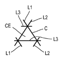
도 5는 삼각형-형상의 폐쇄형 기본 셀을 가지는 패턴의 상세도이다.
도 6은 크레넬형 라인(crenellated line) 및 부분적으로 폐쇄된 기본 셀로 구성된 패턴의 상세도이다.
도 7은 사인파형 라인 및 부분적으로 폐쇄된 기본 셀로 구성된 패턴의 상세도이다.
도 8은 타원형 형상의 폐쇄형 기본 셀로 구성된 패턴의 상세도이다.1 is a schematic front view of an additive manufacturing machine according to the present invention.
2 is a cross-sectional view of a pattern imprinted into a building platform according to the method according to the present invention.
3 is a top view of an additive manufacturing building platform prepared according to the method according to the present invention and having an open type pattern.
4 is a top view of an additive manufacturing building platform prepared according to the method according to the invention and having a closed type pattern.
5 is a detailed view of a pattern having a triangular-shaped closed basic cell.
6 is a detailed view of a pattern consisting of a crenellated line and a partially closed basic cell.
7 is a detailed view of a pattern consisting of sinusoidal lines and partially closed basic cells.
8 is a detailed view of a pattern composed of an oval-shaped closed basic cell.
본 발명은 분말 베드 침착에 의한 적층 제조의 프로세스의 구현을 위한 적층 제조 기계에서 이용되는 구축 플랫폼을 준비하기 위한 방법에 관한 것이다.The present invention relates to a method for preparing a building platform for use in an additive manufacturing machine for implementation of a process of additive manufacturing by powder bed deposition.
분말 베드 침착에 의한 적층 제조는, 서로 중첩된 적층 제조 분말의 다양한 층들의 선택적인 용융에 의해서 하나 이상의 물품이 제조되는 적층 제조 프로세스이다. 분말의 제1 층이 플랫폼과 같은 지지부 상으로 침착되고, 이어서 제조되는 물품 또는 물품들의 제1 수평 섹션을 따라 하나 이상의 에너지 또는 열 공급원을 이용하여 선택적으로 소결 또는 용융된다. 다음에, 분말의 제2 층이, 방금 용융 또는 소결된 분말의 제1 층 상으로 침착되고, 이러한 분말의 제2 층이 다시 선택적으로 소결 또는 용융되며, 제조되는 물품 또는 물품들의 마지막 수평 섹션의 제조에서 이용되는 마지막 분말의 층까지, 이러한 것이 계속된다.Additive manufacturing by powder bed deposition is an additive manufacturing process in which one or more articles are made by selective melting of various layers of additive manufacturing powder superimposed on each other. A first layer of powder is deposited onto a support, such as a platform, and then optionally sintered or melted using one or more energy or heat sources along a first horizontal section of the article or articles being manufactured. Next, a second layer of powder is deposited onto the first layer of powder that has just been melted or sintered, and the second layer of this powder is again selectively sintered or melted, and This continues until the last layer of powder used in manufacturing.
도 1은 분말의 베드를 침착시킴으로써 물품의 적층 제조를 구현할 수 있게 하는 적층 제조 기계(10)를 도시한다. 이러한 적층 제조 기계(10)는 구축 챔버(12), 및 하나 이상의 빔(16)을 통해서 구축 챔버(12) 내측에 침착된 적층 제조 분말의 층을 선택적으로 용융(융합)시키기 위해서 이용되는 열 또는 에너지의 적어도 하나의 공급원(14)을 포함한다.1 shows an
열 또는 에너지 공급원 또는 공급원들(14)은 하나 이상의 전자 빔 및/또는 하나 이상의 레이저 빔을 생산할 수 있는 공급원의 형태를 가질 수 있다. 이러한 공급원은, 예를 들어, 하나 이상의 전자총 및/또는 레이저 빔을 방출할 수 있는 하나 이상의 공급원이다. 선택적인 융합을 허용하기 위해서 그리고 그에 따라 에너지 또는 열의 빔 또는 빔들(16)이 이동될 수 있게 허용하기 위해서, 각각의 공급원(14)은 빔 또는 빔들(16)을 이동시키고 제어하기 위한 수단을 포함한다.The heat or energy source or
구축 챔버(12)는 폐쇄형 챔버이다. 이러한 구축 챔버(12)의 하나의 벽은, 챔버 내의 제조의 진행을 관찰할 수 있도록, 창을 포함할 수 있다. 이러한 구축 챔버(12)의 적어도 하나의 벽은 유지보수 또는 세정 동작을 위한 챔버 내측에의 접근을 제공하는 개구부를 포함하고, 이러한 개구부는 제조 사이클 중에 도어에 의해서 다시 밀봉 폐쇄될 수 있다. 제조 사이클 중에, 적층 제조 분말의 산화를 방지하기 위해서 및/또는 폭발 위험을 방지하기 위해서, 구축 챔버(12)는 질소와 같은 불활성 가스로 충진될 수 있다. 구축 챔버(12)는 산소의 진입을 방지하기 위해서 약간 과압으로 유지될 수 있거나, 분말이 외부로 빠져 나가는 것을 방지하기 위해서 또는 분말을 소결 또는 융합시키기 위해서 전자 빔이 챔버 내에서 이용될 때 진공 하에서 유지될 수 있다. The
구축 챔버(12) 내측에서, 적층 제조 기계(10)는: 수평 작업 평면(18), 및 작업 평면(18) 내에 위치되는 적어도 하나의 구축 구역(20)을 포함한다. 구축 구역(20)은 수평 작업 평면(18) 내에 만들어진 개구부(21)에 의해서 그리고 구축 슬리브(22) 및 구축 플랫폼(24)에 의해서 형성된다. 슬리브(22)는 작업 평면(18) 아래에서 수직으로 연장되고, 개구부(21)를 통해서 작업 평면(18) 내로 개방된다. 구축 플랫폼(24)은, 램(ram)과 같은 작동기(26)의 영향 하에서, 구측 슬리브(22) 내에서 수직으로 활주된다.Inside the
제조되는 물품 또는 물품들의 적층 제조에서 이용되는 분말의 여러 층을 생성하기 위해서, 적층 제조 기계는, 구축 챔버 내에 위치되는 구축 구역(20)에 근접하여 이동될 수 있는 2개의 이동 가능 분말 수용 표면(28)을 포함한다. 적층 제조 기계는 또한, 분말을 이동 가능 수용 표면(28)으로부터 구축 구역(20)을 향해서 확전시키는 역할을 하는 분말 확전 장치(30), 및 각각의 이동 가능 수용 표면(28) 위에 제공된 분말 분배 장치(32)를 포함한다.In order to produce the article being manufactured or several layers of powder used in the additive manufacturing of articles, the additive manufacturing machine has two movable powder receiving surfaces that can be moved close to the
확전 장치(30)는 캐리지(35)에 장착된 스크레이퍼 및/또는 하나 이상의 롤러(34)의 형태를 갖는다. 이러한 캐리지(35)는 구축 구역(20) 위에서 길이방향(D35)을 따라 병진운동으로 이동될 수 있게 장착된다. 길이방향(D35)을 따른 병진운동으로 구동되게 하기 위해서, 구축 챔버(12)의 내측에 또는 바람직하게 외측에 위치된 모터에 의해서 그리고 풀리 및 벨트와 같은 운동-전달 시스템을 통해서, 캐리지(35)가 동력 구동될(motorized) 수 있거나, 이동되게 설정될 수 있다.The
이동 가능 분말 수용 표면(28)은, 분말 확전 장치(30)의 캐리지(35)의 이동과 관련된 길이방향(D35)에 바람직하게 수직인 방향을 따라 병진운동으로 이동되게 장착된 활주부(36)의 형태를 취한다. 더 구체적으로, 활주부(36)는 후퇴 위치와 전개 위치 사이에서 이동될 수 있고, 후퇴 위치에서 이러한 활주부는 분말 확전 장치(30)의 궤적의 외측에 위치되고, 전개 위치에서 이러한 활주부는 적어도 부분적으로 분말 확전 장치(30)의 궤적 내로 연장된다.The movable
분말 분배 장치(32)는 각각의 활주부(36) 위에 제공되고, 그에 따라 각각의 이동 가능 수용 표면(28) 위에 제공된다.A
각각의 서랍부(drawer)(36)가, 구축 구역(20)에 근접한 구축 챔버(12)의 작업 평면(18) 내에 제공된 홈(38) 내에서 병진운동으로 이동되도록 장착된다. 각각의 슬롯(38)은, 각각의 활주부에 의해서 형성된 이동 가능 분말-수용 표면(28)이 작업 평면(18) 내에서 이동하도록 하는 방식으로, 배열된다. 다시 말해서, 활주부(36)가 전개 위치에 있을 때, 이러한 활주부에 의해서 형성된 수용 표면(28)은 작업 평면의 상부 표면(S18)의 연속으로 위치된다.Each
구축 구역(20) 부근에서 그리고 작업 평면(18) 내에서 병진운동으로 이동될 수 있게 장착됨으로써, 각각의 활주부(36)는 구축 구역(20)의 근접부에서 매우 적은 양의 공간을 차지한다.By being mounted to be translatable in the vicinity of the
각각의 이동 가능 수용 표면(28)이 병진운동적으로 이동될 수 있는 활주부의 형태를 가지기 때문에, 구축 구역(20)은 바람직하게 직사각형 형상이고 구축 플랫폼(24)은 바람직하게 평행육면체이다. 그러나, 구축 구역(20) 그리고 그에 따라 구축 플랫폼(24)은 또한, 예를 들어 원형, 계란형 또는 환형 형상과 같은, 제조되는 물품 또는 물품들의 형상에 보다 적합한 다른 형상을 가질 수 있다.Since each movable receiving
구축 플랫폼(24) 상에서 제1 분말 층을 생성하기 위해서, 분말 분배 장치(32)는 분말의 라인을 이동 가능 수용 표면(28) 상에 침착시킨다. 이를 위해서, 이동 가능 수용 표면(28)은 분말 분배 장치(32)의 아래에서 이동되고, 분말 분배 장치(32)는 적합한 그리고 제어된 유량의 분말을, 이동 가능 분말 수용 표면(28)이 아래에서 이동되는, 적어도 하나의 분배 지점에서 전달한다. 이어서, 분말 확전 장치의 스크레이퍼 및/또는 롤러(들)가 구축 플랫폼(24) 위의, 그리고 더 정확하게 이러한 플랫폼의 상부 표면(40) 상의 분말의 라인을 확전시킨다.In order to create a first powder layer on the
본 발명은, 이러한 구축 플랫폼 상에서 제1 분말 층의 균질한 분배를 보장하기 위한 적층 제조 구축 플랫폼(24)의 상부 표면(40)을 준비하기 위한 방법에 관한 것이다.The present invention relates to a method for preparing the
그러한 목적을 위해서, 준비 방법은, 구축 플랫폼(24)의 상부 표면(40)의 적어도 하나의 영역 상으로 패턴(M)을 각인하는 것에 의해서, 이러한 영역의 조도를 증가시키는 적어도 하나의 단계를 포함한다.For that purpose, the preparation method comprises at least one step of increasing the roughness of this area by imprinting the pattern M onto at least one area of the
또한, 본 발명에 따른 준비 방법은, 패턴(M)의 각인이 분말 베드 침착에 의한 적층 제조를 위한 기계(10) 내에서 이루어지는 것을 제공하고, 여기에서 구축 플랫폼(24)은 분말 베드 침착에 의한 적층 제조를 위해서 후속하여 이용된다. 본 발명에 따라, 패턴(M)을 각인하는 것은, 분말의 층이 구축 플랫폼(24) 위에서 확전되기 전에 이루어진다.Further, the preparation method according to the invention provides that the imprinting of the pattern M is made in a
샌드블래스팅 또는 가공 기계 그리고 소모재의 이용을 피하는 것에 의해서, 구축 플랫폼(24)의 준비 비용이 감소된다. 또한, 분말 베드 침착에 의한 적층 제조의 프로세스를 실행하기 위해서 후속하여 이용되는 기계 내에서 직접적으로 패턴(M)을 생성함으로써, 이러한 구축 플랫폼(24)을 준비하는데 필요한 시간이 또한 단축된다.By avoiding the use of sandblasting or processing machines and consumables, the cost of preparing the
더 구체적으로, 분말 베드 침착에 의한 적층 제조를 위한 기계(10)는 적층 제조 분말의 층을 선택적으로 용융시키기 위해서 이용되는 적어도 하나의 에너지 또는 열의 공급원(14)을 포함하고, 본 발명에 따른 준비 방법은, 분말을 선택적으로 용융시키기 위해서 후속하여 이용되는 에너지 또는 열의 공급원(14)으로, 패턴(M)이 구축 플랫폼의 상부 표면(40) 상에 각인되는 것을 제공한다.More specifically, the
보다 더 구체적으로, 분말 베드 침착에 의한 적층 제조를 위한 기계(10)는 적층 제조 분말의 층을 선택적으로 용융시키기 위해서 이용되는 적어도 하나의 레이저 빔(16)을 방출하는 적어도 하나의 공급원(14)을 포함하고, 패턴(M)은, 분말을 선택적으로 용융시키기 위해서 후속하여 이용되는 레이저 빔(16)으로, 구축 플랫폼(24)의 상부 표면(40) 상으로 각인된다.Even more specifically, the
분말을 선택적으로 용융시키기 위해서 후속하여 사용되는 레이저 빔(16)을 이용하는 것은, 패턴(M)의 생성에 있어서의 양호한 정밀도 및 이러한 패턴(M)의 생성에 있어서의 양호한 반복 가능성을 보장한다.Using the
패턴(M)의 생성에 있어서의 양호한 정밀도 및 이러한 패턴(M)의 생성에 있어서의 양호한 반복 가능성은 또한 기계 내의 구축 플랫폼의 장착에 의해서 보장되며, 그러한 장착은, 에너지 또는 열의 공급원(14)과 관련하여 구축 플랫폼을 참조하는 것(referencing), 그리고 그에 따라 에너지 또는 열의 공급원(14)에 대해서 구축 판을 정밀하게 배치하는 것을 암시한다.The good precision in the generation of the pattern M and the good repeatability in the generation of this pattern M are also ensured by the mounting of the building platform in the machine, which mounting is achieved with the
구축 플랫폼의 상부 표면(40) 상에서 분말 입자를 유지할 수 있게 하는, 조도 즉, 양각 형상을 생성하기 위해서, 준비 방법은 구축 플랫폼의 상부 표면 위로 상승되는 패턴(M)을 제공한다.In order to create a roughness, that is, a relief shape, which makes it possible to retain the powder particles on the
도 2는 레이저 빔(16)으로 구축 플랫폼의 상부 표면(40) 상에 패턴(M)을 생성하는 것을 도시한다. 반복 가능성 때문에, 패턴(M)과 구축 플랫폼(24)의 두께 사이의 치수적 비례는 고려되지 않고, 그러한 것은 실제에 상응하지 않는다. 더 구체적으로, 구축 플랫폼(24) 상의 빔의 충격 지점에서, 빔의 에너지에 의해서 구축 플랫폼의 재료가 용융되고 뒤쪽으로 밀려난다. 이는, 적어도 하나의, 도 2에 도시된 예에서 2개의 돌출부(P)에 의해서 상부 표면(40) 내에 형성된 패턴(M)을 초래한다. 이러한 돌출부는 구축 플랫폼의 재료로부터 형성된다. 이러한 돌출부(P)는 상부 표면(40) 위로 상승되고, 돌출부는, 적어도, 구축 플랫폼(24)의 상부 표면(40)에 평행한 방향으로 연장된다. 이러한 그리고 이들 돌출부(P)는 구축 플랫폼의 상부 표면(40) 내에서의 레이저 빔의 작용에 의해서 비워진(hollowed) 채널(G)에 접경될 수 있다. 스케일(scale)에 관한 생각을 제공하기 위해서, 구축 플랫폼(24)의 두께가 몇 센티미터일 때, 돌출부 또는 돌출부들(P)은 상부 표면(40) 위로 몇십 마이크로미터로 상승된다. 이러한 돌출부(P)는, 분말 확전 장치(30)가 작용할 때, 분말 입자가 판(24)의 상부 표면(40) 상에서 유지되게 할 수 있을 것이다.2 shows the creation of a pattern M on the
파워가 매우 감소된 레이저 빔으로 얻어지는 제1 변형예에 따라, 패턴(M)은, 재료를 뒤쪽으로 미는 것에 의해서 획득된 하나의 돌출부(P)에 의해서 구축 플랫폼(24)의 상부 표면(40) 위에 형성된다. 더 큰 파워의 레이저 빔으로 얻어지는 다른 변형예에 따라, 패턴(M)은 채널(G)에 접경되는 하나의 돌출부(P)에 의해서 또는 채널(G)의 양 측면에 위치되는 2개의 돌출부(P)에 의해서 구축 플랫폼(24)의 상부 표면(40) 위에 형성된다.According to a first variant obtained with a laser beam with very reduced power, the pattern M is the
도 3에 도시된 바와 같이, 패턴(M)은 적어도 하나의, 복수의 병치된 라인(L)을 포함한다. 도 3 및 도 4의 판독성(legibility) 때문에, 패턴(M)의 라인(L)과 구축 플랫폼(24)의 치수(길이 및 폭) 사이의 치수적 비례는 고려되지 않고, 그러한 것은 실제에 상응하지 않는다.As shown in FIG. 3, the pattern M includes at least one, a plurality of juxtaposed lines L. Because of the legibility of Figs. 3 and 4, the dimensional proportionality between the line L of the pattern M and the dimensions (length and width) of the
구축 플랫폼을 준비하는데 필요한 시간을 줄이기 위해서 그리고 구축 플랫폼(24) 상의 분말의 균일한 분배를 촉진하기 위해서, 라인(L)은 바람직하게 직선형이고, 평행하고, 서로 규칙적으로 이격된다.In order to reduce the time required to prepare the building platform and to promote even distribution of the powder on the
스케일에 관한 생각을 제공하기 위해서, 그리고 100 마이크로미터 미만의 입자 크기를 갖는 분말의 부착을 가능하게 하기 위해서, 2개의 인접 라인(L) 사이의 간격(E)은 바람직하게 1 내지 5 밀리미터이다.In order to give an idea of the scale, and to enable the adhesion of powders having a particle size of less than 100 micrometers, the spacing E between two adjacent lines L is preferably between 1 and 5 millimeters.
도 4에 도시된 바와 같이, 그리고 구축 플랫폼(24) 상의 분말의 균일한 분배를 더 촉진하기 위해서, 패턴(M)은 병치된 라인(L1)의 제1 그룹(G1) 및 병치된 라인(L2)의 제2 그룹(G2)을 포함하고, 제1 그룹의 적어도 하나의 라인(L1)은 제2 그룹의 적어도 하나의 라인(L2)과 교차된다.As shown in Fig. 4, and to further promote the even distribution of the powder on the
바람직하게, 제1 그룹(G1)의 라인(L1)이 직선형이고, 평행하며, 규칙적으로 이격되고, 제2 그룹(G2)의 라인(L2)이 직선형이고, 평행하며, 규칙적으로 이격되고, 패턴(M)이 그리드의 형태를 취하도록 제1 그룹의 라인과 제2 그룹의 라인이 교차된다. 이러한 종류의 그리드는, 구축 플랫폼(24) 상의 제1 분말 층의 부착을 크게 촉진하는 역할을 하는 복수의 기본 셀(CE)을 형성한다.Preferably, the lines L1 of the first group G1 are straight, parallel, and regularly spaced apart, and the lines L2 of the second group G2 are straight, parallel, regularly spaced, and patterned. The lines of the first group and the lines of the second group are intersected so that (M) takes the form of a grid. This kind of grid forms a plurality of basic cells CE that serve to greatly promote the adhesion of the first powder layer on the
또한 구축 플랫폼(24) 상의 분말의 균일한 분배를 더 촉진하기 위해서, 제1 그룹(G1)의 라인(L1)은 바람직하게 제2 그룹(G2)의 라인(L2)에 수직이다.In addition, in order to further promote even distribution of the powder on the
레이저의 작업 시간 그리고 그에 따라 구축 플랫폼(24)을 준비하기 위한 시간을 줄이기 위해서, 라인(L, L1, L2)은 바람직하게 연속적이다.In order to reduce the working time of the laser and thus the time to prepare the
분말 확전 장치(30)가 작용할 때 라인(L, L1, L2)이 분말 입자를 양호하게 유지할 수 있게 보장하기 위해서, 패턴(M)의 적어도 복수의 라인(L)은, 길이방향(D35)에 수직이지 않은 횡방향(DT)에 평행하게 연장된다.In order to ensure that the lines L, L1, L2 can hold the powder particles satisfactorily when the
바람직하게, 제1 그룹(G1)의 라인(L1) 및 제2 그룹(G2)의 라인(L2) 모두가, 길이방향(D35)에 수직이지 않은 각각의 횡방향(DT1 및 DT2)에 평행하게 연장된다.Preferably, both the line L1 of the first group G1 and the line L2 of the second group G2 are parallel to each of the transverse directions DT1 and DT2 that are not perpendicular to the longitudinal direction D35. Is extended.
분말 확전 장치(30)가 작용할 때 라인(L, L1, L2)이 분말 입자를 최적으로 유지할 수 있게 보장하기 위해서, 패턴(M)의 적어도 복수의 라인(L, L1, L2)이 횡방향(DT, DT1, DT2)에 평행하게 연장되고, 길이방향(D35)에 대한 그러한 횡방향(DT, DT1, DT2)의 시계방향 또는 반시계방향 경사 각도(α, α1, α2)는 25도 내지 65도이다.In order to ensure that the lines (L, L1, L2) can optimally hold the powder particles when the
(예를 들어 20 마이크로미터 미만의 매우 작은 입자 크기로 인해서, 또는 그 높은 습도로 인해서) 균일하게 확전시키기가 어려운 이러한 분말의 균일한 분배를 가능하게 할 수 있는 패턴(M)의 변형예에서, 패턴(M)의 라인 중 제1 그룹(G1)의 라인(L1)이 길이방향(D35)에 대해서 시계방향으로 45도로 경사진 제1 횡방향(DT1)에 평행하게 연장되고, 패턴(M)의 라인 중 제2 그룹(G2)의 라인(L2)이 길이방향(D35)에 대해서 반시계방향으로 45도로 경사진 제2 횡방향(DT2)에 평행하게 연장된다.In a variant of the pattern (M) that can enable a uniform distribution of such powders that are difficult to spread evenly (for example due to a very small particle size of less than 20 micrometers, or due to their high humidity), Among the lines of the pattern M, the line L1 of the first group G1 extends parallel to the first transverse direction DT1 inclined at 45 degrees in the clockwise direction with respect to the length direction D35, and the pattern M Of the lines of, the line L2 of the second group G2 extends parallel to the second transverse direction DT2 inclined at 45 degrees in the counterclockwise direction with respect to the length direction D35.
기본 셀(CE)을 증식시키기 위해서 그리고 도 5에 도시된 바와 같이, 서로 교차되는 라인(L1, L2, L3)의 그룹(G1, G2, G3)의 수를 증가시킬 수 있고, 예에서 3개의 라인의 그룹이 도시되어 있다. 이러한 예에서, 기본 셀(CE)은 삼각형 형상이다.In order to proliferate the base cells CE and as shown in Fig. 5, the number of groups (G1, G2, G3) of the lines (L1, L2, L3) intersecting each other can be increased, in the example 3 Groups of lines are shown. In this example, the basic cell CE has a triangular shape.
변형예로서, 비-선형적 라인을 이용하여 폐쇄된 또는 부분적으로 폐쇄된 기본 셀(CE)을 생성할 수 있다.As a variant, it is possible to create a closed or partially closed basic cell CE using a non-linear line.
도 6은, 크레넬형 라인(LC)을 이용하여 복수의 부분적으로 폐쇄된 기본 셀(CE)을 생성하는 예시적인 패턴(M)을 도시한다.FIG. 6 shows an exemplary pattern M for generating a plurality of partially closed basic cells CE by using the Cranel-shaped line LC.
도 7은, 사인파형 라인(LS)을 이용하여 복수의 부분적으로 폐쇄된 기본 셀(CE)을 생성하는 예시적인 패턴(M)을 도시한다.7 shows an exemplary pattern M for generating a plurality of partially closed basic cells CE using a sinusoidal line LS.
예를 들어 도 8에 도시된, 다른 변형예에서, 패턴(M)은, 실질적으로 기본 셀(CE)에 상응할 수 있는 복수의 기본 패턴(ME)에 의해서 형성된다. 기본 셀(CE)과 마찬가지로, 기본 패턴(ME)은 폐쇄된 또는 부분적으로 폐쇄된 윤곽을 가질 수 있다. 기본 셀(CE)과 마찬가지로, 기본 패턴(ME)은 상이한 형상들: 타원형(도 8), 원형, 다각형, 특히 평행사변형, 마름모형, 육각형 등의 형상일 수 있다.For example, as illustrated in FIG. 8, in another modification, the pattern M is formed by a plurality of basic patterns ME that may substantially correspond to the basic cells CE. Like the basic cell CE, the basic pattern ME may have a closed or partially closed contour. Like the basic cell CE, the basic pattern ME may be of different shapes: oval (FIG. 8), circular, polygonal, especially parallelogram, rhombus, hexagonal, and the like.
라인으로부터 또는 기본 패턴(ME)에 의해서 형성되든지 간에, 패턴(M)은 복수의 병치된 기본 셀(CE)을 포함하고, 각각의 기본 셀(CE)은, 구축 플랫폼 상에서 제1 분말 층을 효과적으로 유지할 수 있게 하기 위해서, 적어도 부분적으로 폐쇄된 윤곽(C)을 갖는다.Whether formed from a line or by a basic pattern ME, the pattern M includes a plurality of juxtaposed basic cells CE, and each basic cell CE effectively deposits a first layer of powder on the building platform. In order to be able to maintain it, it has an at least partially closed contour C.
구축 플랫폼(24) 상에서의 제1 분말 층의 양호한 부착을 보장하기 위해서, 각각의 기본 셀의 윤곽(C)이 그 길이의 적어도 50%에 걸쳐 폐쇄된다.In order to ensure good adhesion of the first powder layer on the
입자 크기가 100 마이크로미터 미만인 분말의 최적의 분배를 위해서, 각각의 기본 셀(CE)의 표면적은 4 내지 25 mm2이다.For optimal distribution of powders with a particle size of less than 100 micrometers, the surface area of each basic cell (CE) is 4 to 25 mm 2 .
일반적으로, 그 목적은, 분말 베드 침착에 의한 적층 제조 중에 구축 플랫폼(24)의 상부 표면(40)의 이용을 최적화하기 위한 것이다. 또한, 패턴(M)은 바람직하게 적층 제조 구축 플랫폼의 전체 상부 표면(40) 상으로 각인된다.In general, its purpose is to optimize the use of the
본 발명은, 전술한 준비 방법에 따라 준비되는, 분말 베드 침착에 의한 적층 제조를 위한 구축 플랫폼(24)을 포함한다. 재료의 제거에 의해서 조도를 생성하기 위한 샌드블래스팅 또는 가공을 거친 구축 플랫폼과 비교하면, 본 발명에 따라 준비된 구축 플랫폼(24)은, 구축 플랫폼의 상부 표면(40) 위로 상승된 돌출부(P)에 의해서 생성된 조도에 의해서 그리고 미세-홈 또는 미세 공동과 같은 중공형 형상보다 양호한 분말 입자의 유지를 제공하는 것에 의해서, 차별화된다. The present invention includes a
본 발명은 또한, 전술한 준비 방법에 따라 구현되는, 구축 플랫폼(24)을 준비하는 단계를 포함하는, 분말 베드 침착에 의한 적층 제조 프로세스를 포함한다. 그러한 제조 프로세스는 예를 들어 적층 제조 기계(10) 내에서 실시되고, 그러한 기계(10)는 구축 플랫폼(24), 이러한 구축 플랫폼 상에서 적층 제조 분말의 층을 확전시키기 위한 장치(30), 및 적층 제조 분말의 층을 선택적으로 용융시키기 위해서 이용되는 적어도 하나의 에너지 또는 열의 공급원(14)을 포함한다.The present invention also includes an additive manufacturing process by powder bed deposition, comprising the step of preparing the
이러한 제조 프로세스에 따라, 구축 플랫폼(24)은 적층 제조 기계(10) 내에 장착되고, 이어서 전술한 준비 방법에 따라 준비된다.According to this manufacturing process, the
또한 이러한 제조 프로세스에 따라, 구축 플랫폼(24)은 전술한 준비 방법에 따라 준비되고, 이어서 분말 베드 침착에 의해서 물품을 적층 제조하기 위해서 후속하여 이용된다.Also according to this manufacturing process, the
이상적으로, 이러한 제조 프로세스에 따라, 구축 플랫폼(24)은 적층 제조 기계(10) 내에 장착되고, 전술한 준비 방법에 따라 준비되고, 이어서 분말 베드 침착에 의해서 물품을 적층 제조하기 위해서 이용된다.Ideally, according to this manufacturing process, the
준비 방법, 이러한 방법으로 준비된 구축 플랫폼(24), 및 이러한 준비 방법을 포함하는 적층 제조 프로세스는, 50 마이크로미터 미만의 입자 크기를 갖는 분말과 함께 이용될 때, 특히 관심의 대상이 되는데, 이는, 분말의 입자 크기가 비교적 작을 때에도, 그러한 분말의 균질한 분배를 보장할 수 있기 때문이다.The preparation method, the
Claims (23)
분말 베드 침착에 의한 적층 제조를 위한 기계(10)는 적층 제조 분말의 층을 선택적으로 용융시키기 위해서 이용되는 적어도 하나의 에너지 또는 열의 공급원(14)을 포함하고, 패턴(M)은, 분말을 선택적으로 용융시키기 위해서 후속하여 이용되는 에너지 또는 열의 공급원으로, 구축 플랫폼의 상부 표면(40) 상에 각인되는, 분말 베드 침착에 의한 적층 제조를 위해서 구축 플랫폼(24)의 상부 표면(40)을 준비하기 위한 방법.The method of claim 1,
The machine 10 for additive manufacturing by powder bed deposition comprises at least one source of energy or heat 14 used to selectively melt a layer of additive manufacturing powder, and the pattern M selects the powder. To prepare the top surface 40 of the building platform 24 for additive manufacturing by powder bed deposition, imprinted on the top surface 40 of the building platform, as a source of energy or heat that is subsequently used to melt it. Way for you.
분말 베드 침착에 의한 적층 제조를 위한 기계(10)는 적층 제조 분말의 층을 선택적으로 용융시키기 위해서 이용되는 적어도 하나의 레이저 빔(16)을 방출하는 적어도 하나의 공급원(14)을 포함하고, 패턴(M)은, 분말을 선택적으로 용융시키기 위해서 후속하여 이용되는 레이저 빔으로, 구축 플랫폼의 상부 표면(40) 상으로 각인되는, 분말 베드 침착에 의한 적층 제조를 위해서 구축 플랫폼(24)의 상부 표면(40)을 준비하기 위한 방법.The method according to claim 1 or 2,
The machine 10 for additive manufacturing by powder bed deposition comprises at least one source 14 that emits at least one laser beam 16 used to selectively melt a layer of additive manufacturing powder, and the pattern (M) is the top surface of the building platform 24 for additive manufacturing by powder bed deposition, imprinted onto the top surface 40 of the building platform, with a laser beam subsequently used to selectively melt the powder. Method for preparing 40.
패턴(M)이 구축 플랫폼의 상부 표면(40) 위로 상승되는, 분말 베드 침착에 의한 적층 제조를 위해서 구축 플랫폼(24)의 상부 표면(40)을 준비하기 위한 방법.The method according to any one of claims 1 to 3,
A method for preparing the top surface 40 of the building platform 24 for additive manufacturing by powder bed deposition, wherein the pattern M is raised above the top surface 40 of the building platform.
패턴(M)이 적어도 하나의, 복수의 병치된 라인(L)을 포함하는, 분말 베드 침착에 의한 적층 제조를 위해서 구축 플랫폼(24)의 상부 표면(40)을 준비하기 위한 방법.The method according to any one of claims 1 to 4,
A method for preparing the top surface 40 of the building platform 24 for additive manufacturing by powder bed deposition, wherein the pattern M comprises at least one, a plurality of juxtaposed lines L.
라인(L)이 직선형이고, 평행하고, 서로 균일하게 이격되는, 분말 베드 침착에 의한 적층 제조를 위해서 구축 플랫폼(24)의 상부 표면(40)을 준비하기 위한 방법.The method of claim 5,
A method for preparing the top surface 40 of the building platform 24 for additive manufacturing by powder bed deposition, where the lines L are straight, parallel and evenly spaced from each other.
2개의 인접한 라인(L) 사이의 간격(E)이 1 내지 5 밀리미터인, 분말 베드 침착에 의한 적층 제조를 위해서 구축 플랫폼(24)의 상부 표면(40)을 준비하기 위한 방법.The method of claim 6,
A method for preparing the upper surface 40 of the building platform 24 for additive manufacturing by powder bed deposition, wherein the spacing E between two adjacent lines L is 1 to 5 millimeters.
패턴(M)은 병치된 라인(L1)의 제1 그룹(G1) 및 병치된 라인(L2)의 제2 그룹(G2)을 포함하고, 제1 그룹의 적어도 하나의 라인(L1)이 제2 그룹의 적어도 하나의 라인(L2)과 교차되는, 분말 베드 침착에 의한 적층 제조를 위해서 구축 플랫폼(24)의 상부 표면(40)을 준비하기 위한 방법.The method according to any one of claims 5 to 7,
The pattern M includes a first group G1 of the juxtaposed line L1 and a second group G2 of the juxtaposed line L2, and at least one line L1 of the first group is a second A method for preparing the upper surface 40 of the building platform 24 for additive manufacturing by powder bed deposition, intersecting at least one line L2 of the group.
제1 그룹(G1)의 라인(L1)은 직선형이고, 평행하며, 규칙적으로 이격되고, 제2 그룹(G2)의 라인(L2)은 직선형이고, 평행하며, 규칙적으로 이격되며, 패턴(M)이 그리드의 형태를 취하는 방식으로 제1 그룹의 라인과 제2 그룹의 라인이 교차되는, 분말 베드 침착에 의한 적층 제조를 위해서 구축 플랫폼(24)의 상부 표면(40)을 준비하기 위한 방법.The method of claim 8,
The lines L1 of the first group G1 are straight, parallel, and regularly spaced apart, and the lines L2 of the second group G2 are straight, parallel, and regularly spaced apart, and the pattern M A method for preparing the upper surface 40 of the building platform 24 for additive manufacturing by powder bed deposition, in which the lines of the first group and the lines of the second group intersect in a manner taking the form of this grid.
제1 그룹의 라인(L1)은 제2 그룹의 라인(L2)에 수직인, 분말 베드 침착에 의한 적층 제조를 위해서 구축 플랫폼(24)의 상부 표면(40)을 준비하기 위한 방법.The method of claim 9,
A method for preparing the upper surface 40 of the building platform 24 for additive manufacturing by powder bed deposition, wherein the first group of lines L1 is perpendicular to the second group of lines L2.
라인(L, L1, L2)은 연속적인, 분말 베드 침착에 의한 적층 제조를 위해서 구축 플랫폼(24)의 상부 표면(40)을 준비하기 위한 방법.The method according to any one of claims 5 to 10,
Lines L, L1, L2 are continuous, method for preparing the top surface 40 of the building platform 24 for additive manufacturing by powder bed deposition.
분말 베드 침착에 의해 적층 제조하기 위한 기계(10)는 구축 플랫폼 위에서 길이방향(D35)으로 이동되는 적어도 하나의 분말 확전 장치(30)를 포함하고, 패턴(M)의 복수의 라인(L, L1, L2)은, 길이방향(D35)에 수직이 아닌 횡방향(DT, DT1, DT2)에 평행하게 연장되는, 분말 베드 침착에 의한 적층 제조를 위해서 구축 플랫폼(24)의 상부 표면(40)을 준비하기 위한 방법.The method according to any one of claims 5 to 11,
The machine 10 for additive manufacturing by powder bed deposition comprises at least one powder spreading device 30 which is moved longitudinally (D35) on the building platform, and comprises a plurality of lines (L, L1) of the pattern (M). , L2) extends parallel to the transverse directions (DT, DT1, DT2) and not perpendicular to the longitudinal direction (D35), the upper surface 40 of the building platform 24 for additive manufacturing by powder bed deposition. How to prepare.
패턴(M)의 복수의 라인(L, L1, L2)은, 길이방향(D35)에 대한 시계방향 또는 반시계방향의 경사 각도(α, α1, α2)가 25도 내지 65도인 횡방향(DT, DT1, DT2)에 평행하게 연장되는, 분말 베드 침착에 의한 적층 제조를 위해서 구축 플랫폼(24)의 상부 표면(40)을 준비하기 위한 방법.The method of claim 12,
The plurality of lines (L, L1, L2) of the pattern (M) are in the lateral direction (DT , DT1, DT2). A method for preparing the top surface 40 of the building platform 24 for additive manufacturing by powder bed deposition, extending parallel to DT1, DT2).
패턴(M)의 라인 중 제1 그룹(G1)의 라인(L1)은, 길이방향(D35)에 대해서 시계방향으로 45도로 경사진 제1 횡방향(DT1)에 평행하게 연장되고, 패턴(M)의 라인 중 제2 그룹(G2)의 라인(L2)은, 길이방향(D35)에 대해서 반시계방향으로 45도로 경사진 제2 횡방향(DT2)에 평행하게 연장되는, 분말 베드 침착에 의한 적층 제조를 위해서 구축 플랫폼(24)의 상부 표면(40)을 준비하기 위한 방법.The method of claim 13,
Of the lines of the pattern M, the line L1 of the first group G1 extends parallel to the first transverse direction DT1 inclined at 45 degrees in the clockwise direction with respect to the longitudinal direction D35, and the pattern M The line L2 of the second group G2 of the lines of) extends parallel to the second transverse direction DT2, which is inclined at 45 degrees in the counterclockwise direction with respect to the longitudinal direction D35, by powder bed deposition. A method for preparing the top surface 40 of the building platform 24 for additive manufacturing.
패턴(M)은 복수의 병치된 기본 셀(CE)을 포함하고, 각각의 기본 셀은 적어도 부분적으로 폐쇄된 윤곽(C)을 가지는, 분말 베드 침착에 의한 적층 제조를 위해서 구축 플랫폼(24)의 상부 표면(40)을 준비하기 위한 방법.The method according to any one of claims 1 to 14,
The pattern (M) comprises a plurality of juxtaposed base cells (CE), each base cell having an at least partially closed contour (C) of the building platform 24 for additive manufacturing by powder bed deposition. Method for preparing the upper surface 40.
각각의 기본 셀의 윤곽(C)은 그 길이의 적어도 50%에 걸쳐 폐쇄되는, 분말 베드 침착에 의한 적층 제조를 위해서 구축 플랫폼(24)의 상부 표면(40)을 준비하기 위한 방법.The method of claim 15,
A method for preparing the top surface 40 of the building platform 24 for additive manufacturing by powder bed deposition, wherein the contour C of each basic cell is closed over at least 50% of its length.
각각의 기본 셀의 윤곽(C)은 그 길이의 전체에 걸쳐 폐쇄되는, 분말 베드 침착에 의한 적층 제조를 위해서 구축 플랫폼(24)의 상부 표면(40)을 준비하기 위한 방법.The method of claim 16,
A method for preparing the top surface 40 of the building platform 24 for additive manufacturing by powder bed deposition, wherein the contour C of each basic cell is closed throughout its length.
각각의 기본 셀(CE)의 표면적이 4 내지 25 mm2인, 분말 베드 침착에 의한 적층 제조를 위해서 구축 플랫폼(24)의 상부 표면(40)을 준비하기 위한 방법.The method according to any one of claims 15 to 17,
A method for preparing the top surface 40 of the building platform 24 for additive manufacturing by powder bed deposition, with a surface area of each base cell (CE) of 4-25 mm 2 .
패턴은 적층 제조 구축 플랫폼의 상부 표면(40)의 전부에 각인되는, 분말 베드 침착에 의한 적층 제조를 위해서 구축 플랫폼(24)의 상부 표면(40)을 준비하기 위한 방법.The method according to any one of claims 1 to 18,
A method for preparing the top surface 40 of the building platform 24 for additive manufacturing by powder bed deposition, wherein the pattern is imprinted on all of the top surface 40 of the additive manufacturing building platform.
구축 플랫폼(24)은 적층 제조 기계(10) 내에 장착되고, 이어서 제1항 내지 제19항 중 어느 한 항에 따른 준비 방법에 따라 준비되는, 분말 베드 침착에 의한 적층 제조를 위한 방법.The method of claim 20,
The building platform (24) is mounted in an additive manufacturing machine (10) and is then prepared according to the preparation method according to any one of claims 1 to 19. A method for additive manufacturing by powder bed deposition.
판(24)은 제1항 내지 제19항 중 어느 한 항에 따른 준비 방법에 따라 준비되고, 이어서 분말 베드 침착에 의한 물품의 적층 제조를 위해서 후속하여 이용되는, 분말 베드 침착에 의한 적층 제조를 위한 방법.The method of claim 20 or 21,
The plate (24) is prepared according to the preparation method according to any one of claims 1 to 19, followed by additive manufacturing by powder bed deposition, which is subsequently used for the additive manufacturing of articles by powder bed deposition. Way for you.
제조 방법에 의해서 이용되는 적층 제조 분말은 50 마이크로미터 미만의 입자 크기를 가지는, 분말 베드 침착에 의한 적층 제조를 위한 방법.The method according to any one of claims 20 to 22,
A method for additive manufacturing by powder bed deposition, wherein the additive manufacturing powder used by the manufacturing method has a particle size of less than 50 microns.
Applications Claiming Priority (3)
| Application Number | Priority Date | Filing Date | Title |
|---|---|---|---|
| FR1854445 | 2018-05-25 | ||
| FR1854445A FR3081375B1 (en) | 2018-05-25 | 2018-05-25 | METHOD FOR PREPARING THE UPPER SURFACE OF AN ADDITIVE MANUFACTURING TRAY BY POWDER BED DEPOSIT |
| PCT/FR2019/051194 WO2019224497A1 (en) | 2018-05-25 | 2019-05-23 | Method for preparing the upper surface of an additive manufacturing platen by depositing a bed of powder |
Publications (1)
| Publication Number | Publication Date |
|---|---|
| KR20210013562A true KR20210013562A (en) | 2021-02-04 |
Family
ID=63407371
Family Applications (1)
| Application Number | Title | Priority Date | Filing Date |
|---|---|---|---|
| KR1020207033517A KR20210013562A (en) | 2018-05-25 | 2019-05-23 | Method for preparing the top surface of an additive manufacturing platen by depositing a powder bed |
Country Status (7)
| Country | Link |
|---|---|
| US (1) | US20210213536A1 (en) |
| EP (1) | EP3802130A1 (en) |
| JP (1) | JP2021525313A (en) |
| KR (1) | KR20210013562A (en) |
| CN (1) | CN112188962A (en) |
| FR (1) | FR3081375B1 (en) |
| WO (1) | WO2019224497A1 (en) |
Families Citing this family (2)
| Publication number | Priority date | Publication date | Assignee | Title |
|---|---|---|---|---|
| EP3068929B2 (en) * | 2013-11-14 | 2021-09-22 | General Electric Company | Layered manufacturing of single crystal alloy components |
| US20230052299A1 (en) * | 2020-02-24 | 2023-02-16 | Hewlett-Packard Development Company, L.P. | Surface roughness application |
Family Cites Families (19)
| Publication number | Priority date | Publication date | Assignee | Title |
|---|---|---|---|---|
| JP3491627B2 (en) * | 2001-06-26 | 2004-01-26 | 松下電工株式会社 | Manufacturing method of three-dimensional shaped object |
| JP2008240074A (en) * | 2007-03-27 | 2008-10-09 | Matsushita Electric Works Ltd | Method for producing three-dimensional shaped molding |
| US9789540B2 (en) * | 2008-02-13 | 2017-10-17 | Materials Solutions Limited | Method of forming an article |
| GB2458745B (en) * | 2008-02-13 | 2013-03-20 | Materials Solutions | A method of forming an article |
| AU2012350466B2 (en) * | 2011-12-16 | 2015-11-26 | Herbert Jennissen | Substrate with a structured surface and methods for the production thereof, and methods for determining the wetting properties thereof |
| GB2500412A (en) * | 2012-03-21 | 2013-09-25 | Eads Uk Ltd | Build Plate for an additive manufacturing process |
| ES2670977T3 (en) * | 2013-02-14 | 2018-06-04 | Renishaw Plc. | Selective laser solidification apparatus and method |
| EP3200942A1 (en) * | 2014-10-01 | 2017-08-09 | Renishaw Plc. | Additive manufacturing apparatus and method |
| EP3228404A4 (en) * | 2014-12-30 | 2018-09-19 | Yuanmeng Precision Technology (Shenzhen) Institut | Multi-electron-beam melting and milling composite 3d printing apparatus |
| TWI726940B (en) * | 2015-11-20 | 2021-05-11 | 美商泰坦脊柱股份有限公司 | Processes for additively manufacturing orthopedic implants |
| CN105328913A (en) * | 2015-11-30 | 2016-02-17 | 天津清研智束科技有限公司 | Powder laying device and additive manufacturing device |
| DE102016207893A1 (en) * | 2016-05-09 | 2017-11-09 | Siemens Aktiengesellschaft | Construction platform for additive manufacturing and processes |
| CN105880594A (en) * | 2016-06-21 | 2016-08-24 | 广东电网有限责任公司电力科学研究院 | Copper alloy powder 3D printing method |
| JP6643643B2 (en) * | 2016-06-22 | 2020-02-12 | パナソニックIpマネジメント株式会社 | Manufacturing method of three-dimensional shaped object |
| CN105935769B (en) * | 2016-07-07 | 2017-11-28 | 四川三阳激光增材制造技术有限公司 | A kind of laser melting coating for 3D printing drip molding etches preparation method |
| JP6824652B2 (en) * | 2016-07-08 | 2021-02-03 | キヤノン株式会社 | 3D modeling method and 3D model manufacturing equipment |
| DE102016222555A1 (en) * | 2016-11-16 | 2018-05-17 | Siemens Aktiengesellschaft | Method for additive production of a component and computer-readable medium |
| CN206474675U (en) * | 2016-11-22 | 2017-09-08 | 上海航天精密机械研究所 | A kind of double scraper power spreading devices of increasing material manufacturing attritive powder |
| US20220168106A1 (en) * | 2019-04-11 | 2022-06-02 | Smith & Nephew, Inc. | Medical devices and methods for forming medical devices containing a build plate |
-
2018
- 2018-05-25 FR FR1854445A patent/FR3081375B1/en active Active
-
2019
- 2019-05-23 KR KR1020207033517A patent/KR20210013562A/en not_active Application Discontinuation
- 2019-05-23 CN CN201980034558.2A patent/CN112188962A/en active Pending
- 2019-05-23 EP EP19737816.9A patent/EP3802130A1/en active Pending
- 2019-05-23 US US17/058,311 patent/US20210213536A1/en active Pending
- 2019-05-23 JP JP2020565895A patent/JP2021525313A/en active Pending
- 2019-05-23 WO PCT/FR2019/051194 patent/WO2019224497A1/en unknown
Also Published As
| Publication number | Publication date |
|---|---|
| EP3802130A1 (en) | 2021-04-14 |
| US20210213536A1 (en) | 2021-07-15 |
| JP2021525313A (en) | 2021-09-24 |
| FR3081375B1 (en) | 2021-12-24 |
| CN112188962A (en) | 2021-01-05 |
| WO2019224497A1 (en) | 2019-11-28 |
| FR3081375A1 (en) | 2019-11-29 |
Similar Documents
| Publication | Publication Date | Title |
|---|---|---|
| RU2729279C1 (en) | Equipment for additive production using combined process of selective electron-beam melting and electron-beam cutting | |
| US20210114106A1 (en) | Selective material dispensing in additive manufacturing | |
| US10646924B2 (en) | Additive manufacturing using a recoater with in situ exchangeable recoater blades | |
| US10926336B2 (en) | Machine and method for powder-based additive manufacturing | |
| US20180311731A1 (en) | High throughput additive manufacturing system | |
| US10406749B2 (en) | Machine and method for powder based additive manufacturing | |
| EP2424707B1 (en) | Additive layer fabrication method | |
| EP3568247B1 (en) | Method and apparatus for continuously refreshing a recoater blade for additive manufacturing | |
| US20170072644A1 (en) | Array of printhead modules for additive manufacturing system | |
| JP6273578B2 (en) | Three-dimensional additive manufacturing apparatus and three-dimensional additive manufacturing method | |
| KR20180061137A (en) | Dispensing and Compressing Materials in Lamination Manufacturing | |
| CN107848208A (en) | The increasing material manufacturing being compacted using electrostatic | |
| US8961860B2 (en) | Laser build up method using vibration and apparatus | |
| KR20180061136A (en) | Selective deposition of powders in laminate manufacturing | |
| US20090033003A1 (en) | Method and Apparatus for the Production of a Workpiece of Exact Geometry | |
| CN107614246B (en) | Device for additive manufacturing of three-dimensional objects | |
| KR20210013562A (en) | Method for preparing the top surface of an additive manufacturing platen by depositing a powder bed | |
| CN111957968A (en) | Composite material increasing and decreasing machining forming device and method | |
| JP6639735B2 (en) | 3D modeling equipment | |
| JP2017530255A (en) | Parts for tire molds, especially powder-based additive manufacturing processes for lining blades | |
| WO2018111418A1 (en) | Additive manufacturing systems and methods | |
| KR20180103332A (en) | 3D laser printing apparatus having powder supplying method using wiper and roller structure | |
| JP2015030883A (en) | Method and apparatus for production of three-dimensional laminate formed object | |
| EP2246143A1 (en) | Additive layer fabrication method | |
| CN114269499A (en) | Recoating machine, lamination molding device provided with same, and lamination molding method |
Legal Events
| Date | Code | Title | Description |
|---|---|---|---|
| WITB | Written withdrawal of application |