KR20210000743A - An optical filter and spectrometer - Google Patents
An optical filter and spectrometer Download PDFInfo
- Publication number
- KR20210000743A KR20210000743A KR1020207037231A KR20207037231A KR20210000743A KR 20210000743 A KR20210000743 A KR 20210000743A KR 1020207037231 A KR1020207037231 A KR 1020207037231A KR 20207037231 A KR20207037231 A KR 20207037231A KR 20210000743 A KR20210000743 A KR 20210000743A
- Authority
- KR
- South Korea
- Prior art keywords
- filter
- optical
- interference coating
- thin film
- downstream
- Prior art date
Links
- 230000003287 optical effect Effects 0.000 title claims abstract description 211
- 238000011144 upstream manufacturing Methods 0.000 claims abstract description 94
- 238000000576 coating method Methods 0.000 claims description 49
- 239000011248 coating agent Substances 0.000 claims description 44
- 239000010409 thin film Substances 0.000 claims description 44
- 239000000758 substrate Substances 0.000 claims description 26
- 238000000034 method Methods 0.000 claims description 25
- 238000001914 filtration Methods 0.000 claims description 5
- 229920000642 polymer Polymers 0.000 claims description 2
- 230000005540 biological transmission Effects 0.000 abstract description 7
- 230000001629 suppression Effects 0.000 abstract description 3
- 230000003595 spectral effect Effects 0.000 description 44
- 238000001228 spectrum Methods 0.000 description 27
- 230000000875 corresponding effect Effects 0.000 description 15
- 238000009826 distribution Methods 0.000 description 8
- 230000002093 peripheral effect Effects 0.000 description 7
- 230000002238 attenuated effect Effects 0.000 description 5
- 239000000463 material Substances 0.000 description 5
- 230000004044 response Effects 0.000 description 5
- 239000011521 glass Substances 0.000 description 4
- 239000007787 solid Substances 0.000 description 4
- 230000007423 decrease Effects 0.000 description 3
- 238000005538 encapsulation Methods 0.000 description 3
- 238000005259 measurement Methods 0.000 description 3
- 238000012986 modification Methods 0.000 description 3
- 230000004048 modification Effects 0.000 description 3
- 238000004088 simulation Methods 0.000 description 3
- 238000010521 absorption reaction Methods 0.000 description 2
- 230000000903 blocking effect Effects 0.000 description 2
- 230000008859 change Effects 0.000 description 2
- 230000001419 dependent effect Effects 0.000 description 2
- 230000000694 effects Effects 0.000 description 2
- 238000009501 film coating Methods 0.000 description 2
- 238000009499 grossing Methods 0.000 description 2
- 238000005286 illumination Methods 0.000 description 2
- 230000010354 integration Effects 0.000 description 2
- 238000004382 potting Methods 0.000 description 2
- 238000012545 processing Methods 0.000 description 2
- 230000001902 propagating effect Effects 0.000 description 2
- 230000009467 reduction Effects 0.000 description 2
- 238000000926 separation method Methods 0.000 description 2
- 125000006850 spacer group Chemical group 0.000 description 2
- 238000003860 storage Methods 0.000 description 2
- 238000000411 transmission spectrum Methods 0.000 description 2
- 238000012935 Averaging Methods 0.000 description 1
- 241000195493 Cryptophyta Species 0.000 description 1
- 229910000530 Gallium indium arsenide Inorganic materials 0.000 description 1
- 230000002745 absorbent Effects 0.000 description 1
- 239000002250 absorbent Substances 0.000 description 1
- 230000001154 acute effect Effects 0.000 description 1
- 238000003491 array Methods 0.000 description 1
- 230000009286 beneficial effect Effects 0.000 description 1
- 230000008901 benefit Effects 0.000 description 1
- 239000000969 carrier Substances 0.000 description 1
- 238000000701 chemical imaging Methods 0.000 description 1
- 230000001143 conditioned effect Effects 0.000 description 1
- 238000001816 cooling Methods 0.000 description 1
- 230000002596 correlated effect Effects 0.000 description 1
- 238000013480 data collection Methods 0.000 description 1
- 238000000151 deposition Methods 0.000 description 1
- 238000001514 detection method Methods 0.000 description 1
- 230000006866 deterioration Effects 0.000 description 1
- 239000006185 dispersion Substances 0.000 description 1
- 230000009977 dual effect Effects 0.000 description 1
- 238000000295 emission spectrum Methods 0.000 description 1
- 230000007613 environmental effect Effects 0.000 description 1
- 238000005530 etching Methods 0.000 description 1
- 238000011049 filling Methods 0.000 description 1
- 239000010408 film Substances 0.000 description 1
- 229910052736 halogen Inorganic materials 0.000 description 1
- 150000002367 halogens Chemical class 0.000 description 1
- 238000003384 imaging method Methods 0.000 description 1
- 230000006872 improvement Effects 0.000 description 1
- 239000011261 inert gas Substances 0.000 description 1
- 238000002955 isolation Methods 0.000 description 1
- 238000004020 luminiscence type Methods 0.000 description 1
- 238000007493 shaping process Methods 0.000 description 1
- 230000004304 visual acuity Effects 0.000 description 1
Images


Classifications
-
- G—PHYSICS
- G01—MEASURING; TESTING
- G01J—MEASUREMENT OF INTENSITY, VELOCITY, SPECTRAL CONTENT, POLARISATION, PHASE OR PULSE CHARACTERISTICS OF INFRARED, VISIBLE OR ULTRAVIOLET LIGHT; COLORIMETRY; RADIATION PYROMETRY
- G01J3/00—Spectrometry; Spectrophotometry; Monochromators; Measuring colours
- G01J3/02—Details
- G01J3/0205—Optical elements not provided otherwise, e.g. optical manifolds, diffusers, windows
- G01J3/0229—Optical elements not provided otherwise, e.g. optical manifolds, diffusers, windows using masks, aperture plates, spatial light modulators or spatial filters, e.g. reflective filters
-
- G—PHYSICS
- G01—MEASURING; TESTING
- G01J—MEASUREMENT OF INTENSITY, VELOCITY, SPECTRAL CONTENT, POLARISATION, PHASE OR PULSE CHARACTERISTICS OF INFRARED, VISIBLE OR ULTRAVIOLET LIGHT; COLORIMETRY; RADIATION PYROMETRY
- G01J3/00—Spectrometry; Spectrophotometry; Monochromators; Measuring colours
- G01J3/02—Details
- G01J3/0205—Optical elements not provided otherwise, e.g. optical manifolds, diffusers, windows
- G01J3/0208—Optical elements not provided otherwise, e.g. optical manifolds, diffusers, windows using focussing or collimating elements, e.g. lenses or mirrors; performing aberration correction
-
- G—PHYSICS
- G01—MEASURING; TESTING
- G01J—MEASUREMENT OF INTENSITY, VELOCITY, SPECTRAL CONTENT, POLARISATION, PHASE OR PULSE CHARACTERISTICS OF INFRARED, VISIBLE OR ULTRAVIOLET LIGHT; COLORIMETRY; RADIATION PYROMETRY
- G01J3/00—Spectrometry; Spectrophotometry; Monochromators; Measuring colours
- G01J3/02—Details
- G01J3/0256—Compact construction
- G01J3/0259—Monolithic
-
- G—PHYSICS
- G01—MEASURING; TESTING
- G01J—MEASUREMENT OF INTENSITY, VELOCITY, SPECTRAL CONTENT, POLARISATION, PHASE OR PULSE CHARACTERISTICS OF INFRARED, VISIBLE OR ULTRAVIOLET LIGHT; COLORIMETRY; RADIATION PYROMETRY
- G01J3/00—Spectrometry; Spectrophotometry; Monochromators; Measuring colours
- G01J3/02—Details
- G01J3/0262—Constructional arrangements for removing stray light
-
- G—PHYSICS
- G01—MEASURING; TESTING
- G01J—MEASUREMENT OF INTENSITY, VELOCITY, SPECTRAL CONTENT, POLARISATION, PHASE OR PULSE CHARACTERISTICS OF INFRARED, VISIBLE OR ULTRAVIOLET LIGHT; COLORIMETRY; RADIATION PYROMETRY
- G01J3/00—Spectrometry; Spectrophotometry; Monochromators; Measuring colours
- G01J3/12—Generating the spectrum; Monochromators
- G01J3/26—Generating the spectrum; Monochromators using multiple reflection, e.g. Fabry-Perot interferometer, variable interference filters
-
- G—PHYSICS
- G01—MEASURING; TESTING
- G01J—MEASUREMENT OF INTENSITY, VELOCITY, SPECTRAL CONTENT, POLARISATION, PHASE OR PULSE CHARACTERISTICS OF INFRARED, VISIBLE OR ULTRAVIOLET LIGHT; COLORIMETRY; RADIATION PYROMETRY
- G01J3/00—Spectrometry; Spectrophotometry; Monochromators; Measuring colours
- G01J3/28—Investigating the spectrum
- G01J3/2803—Investigating the spectrum using photoelectric array detector
-
- G—PHYSICS
- G02—OPTICS
- G02B—OPTICAL ELEMENTS, SYSTEMS OR APPARATUS
- G02B5/00—Optical elements other than lenses
- G02B5/20—Filters
- G02B5/28—Interference filters
- G02B5/285—Interference filters comprising deposited thin solid films
-
- G—PHYSICS
- G01—MEASURING; TESTING
- G01J—MEASUREMENT OF INTENSITY, VELOCITY, SPECTRAL CONTENT, POLARISATION, PHASE OR PULSE CHARACTERISTICS OF INFRARED, VISIBLE OR ULTRAVIOLET LIGHT; COLORIMETRY; RADIATION PYROMETRY
- G01J3/00—Spectrometry; Spectrophotometry; Monochromators; Measuring colours
- G01J3/12—Generating the spectrum; Monochromators
- G01J2003/1213—Filters in general, e.g. dichroic, band
- G01J2003/1221—Mounting; Adjustment
-
- G—PHYSICS
- G01—MEASURING; TESTING
- G01J—MEASUREMENT OF INTENSITY, VELOCITY, SPECTRAL CONTENT, POLARISATION, PHASE OR PULSE CHARACTERISTICS OF INFRARED, VISIBLE OR ULTRAVIOLET LIGHT; COLORIMETRY; RADIATION PYROMETRY
- G01J3/00—Spectrometry; Spectrophotometry; Monochromators; Measuring colours
- G01J3/12—Generating the spectrum; Monochromators
- G01J2003/1226—Interference filters
- G01J2003/1234—Continuously variable IF [CVIF]; Wedge type
-
- G—PHYSICS
- G01—MEASURING; TESTING
- G01J—MEASUREMENT OF INTENSITY, VELOCITY, SPECTRAL CONTENT, POLARISATION, PHASE OR PULSE CHARACTERISTICS OF INFRARED, VISIBLE OR ULTRAVIOLET LIGHT; COLORIMETRY; RADIATION PYROMETRY
- G01J3/00—Spectrometry; Spectrophotometry; Monochromators; Measuring colours
- G01J3/28—Investigating the spectrum
- G01J3/2803—Investigating the spectrum using photoelectric array detector
- G01J2003/2813—2D-array
Abstract
상류 필터가 하류 필터에 대한 공간 필터로서 기능하도록 서로로부터 고정 거리에 스택되는 2개의 측면적 가변 밴드패스 필터들을 포함하는 광학 필터가 개시된다. 이것은 하류 필터에 충돌하는 경우 상류 필터에 의해 송신되는 경사 빔이 측면적으로 배치되기 때문에 발생한다. 측면적 배치는 상류 필터 및 하류 필터로의 경사 빔의 충돌 위치들에서의 송신 패스밴드들이 오버랩하지 않는 경우 경사 빔의 억제를 야기한다.An optical filter is disclosed comprising two laterally variable bandpass filters stacked at a fixed distance from each other such that the upstream filter functions as a spatial filter for the downstream filter. This occurs because the oblique beam transmitted by the upstream filter is disposed laterally when it collides with the downstream filter. The lateral arrangement causes suppression of the oblique beam when the transmission passbands at the collision positions of the oblique beam to the upstream filter and the downstream filter do not overlap.
Description
[0001] 본 개시 내용은 광학 컴포넌트들에 관한 것으로, 특히, 광학 필터들 및 분광계들에 관한 것이다.[0001] TECHNICAL FIELD The present disclosure relates to optical components and, in particular, to optical filters and spectrometers.
[0002] 광학 필터는 유입 광의 스펙트럼 밴드 또는 스펙트럼 컴포넌트를 선택하는데 사용된다. 하이 패스 필터는, 예를 들어, 필터의 에지 파장보다 긴 파장들에서 광을 선택한다. 반대로, 로우 패스 필터는 에지 파장보다 짧은 파장들에서 광을 선택한다. 밴드패스 필터는 별개의 타입의 필터이고, 이는 필터의 대역폭 내에서 필터의 중심 파장에 근접한 파장들에서 광을 선택한다. 튜닝가능한 밴드패스 필터는 광학 필터이고, 이 광학 필터의 중심 파장은 조정 또는 튜닝될 수 있다.[0002] Optical filters are used to select spectral bands or spectral components of incoming light. The high pass filter selects light at wavelengths longer than the filter's edge wavelength, for example. Conversely, the low pass filter selects light at wavelengths shorter than the edge wavelength. A bandpass filter is a separate type of filter, which selects light at wavelengths close to the center wavelength of the filter within the filter's bandwidth. The tunable bandpass filter is an optical filter, and the center wavelength of this optical filter can be tuned or tuned.
[0003] 분광계는 유입 광의 광학 스펙트럼을 측정한다. 스캐닝-타입 분광계는 하나 또는 그 초과의 튜닝가능한 밴드패스 필터들을 사용하여 유입 광의 상이한 스펙트럼 컴포넌트들을 선택할 수 있다. 스캐닝-타입 분광계는 광학 스펙트럼을 획득하도록 튜닝가능한 밴드패스 필터의 중심 파장을 스캐닝함으로써 동작한다. 대안적으로, 다색화기(polychromator)-타입 분광계는 광학 스펙트럼의 병렬 검출을 위한 검출기 어레이에 광학적으로 커플링된 파장-분산 엘리먼트를 사용한다. 그러나, 종래의 광학 필터들 및 분광계들은 전형적으로 크고 부피가 커서, 휴대용 디바이스들 및 애플리케이션들에서 그것들을 사용하는 것을 어렵게 한다.[0003] The spectrometer measures the optical spectrum of the incoming light. The scanning-type spectrometer can select different spectral components of the incoming light using one or more tunable bandpass filters. Scanning-type spectrometers operate by scanning the center wavelength of a tunable bandpass filter to obtain an optical spectrum. Alternatively, a polychromator-type spectrometer uses a wavelength-dispersing element optically coupled to an array of detectors for parallel detection of the optical spectrum. However, conventional optical filters and spectrometers are typically large and bulky, making it difficult to use them in portable devices and applications.
[0004] 위의 내용을 고려하면, 광학 필터들 및 분광계들에 대한 현재 해결책들 및 기술들과 연관된 중요한 문제들 및 단점들이 존재할 수 있다는 것이 이해될 수 있다.[0004] In view of the above, it can be understood that there may be significant problems and disadvantages associated with current solutions and techniques for optical filters and spectrometers.
[0005] 본 개시 내용에 따라, 2개 또는 그 초과의 측면적(laterally) 가변 밴드패스 필터들은 충돌(impinging) 빔 콜리메이션에 대한 요건들을 감소시키기 위해서, 또는 심지어, 테이퍼링된(tapered) 광 파이프 또는 또 다른 광 콜리메이팅 엘리먼트의 필요성을 완전하게 경감시키기 위해서 서로로부터 고정 거리에 스택될 수 있다. 2개의 측면적 가변 밴드패스 필터들이 함께 스택되는 경우, 상류 필터는 하류 필터에 대한 공간 필터로서 기능할 수 있다. 이것은 하류 필터에 충돌하는 경우 상류 필터에 의해 송신되는 경사 빔이 측면적으로 배치되기 때문에 발생한다. 상류 및 하류 필터들 상의 빔 충돌 위치들이 오버랩하지 않는 경우 상류 및 하류 필터들의 송신 파장들이 오버랩하지 않을 수 있어서 경사 빔들의 억제를 초래하기 때문에, 측면적 배치는 경사 빔의 억제를 초래할 수 있다. 이 효과에 기인하여, 상류 필터를 스트라이크(strike)하는 유입 빔의 콜리메이션의 정도에 대한 광학 필터의 스펙트럼 선택성의 의존도는 줄어들 수 있다.[0005] In accordance with the present disclosure, two or more laterally variable bandpass filters are used to reduce the requirements for impinging beam collimation, or even, a tapered light pipe or another They can be stacked at a fixed distance from each other to completely alleviate the need for optical collimating elements. When two laterally variable bandpass filters are stacked together, the upstream filter can function as a spatial filter for the downstream filter. This occurs because the oblique beam transmitted by the upstream filter is disposed laterally when it collides with the downstream filter. Since the transmission wavelengths of the upstream and downstream filters may not overlap, resulting in suppression of the oblique beams when the beam collision positions on the upstream and downstream filters do not overlap, the lateral arrangement may result in suppression of the oblique beam. Due to this effect, the dependence of the spectral selectivity of the optical filter on the degree of collimation of the incoming beam striking the upstream filter can be reduced.
[0006] 본 개시 내용의 양상에 따라, 상류 측면적 가변 밴드패스 광학 필터 및 하류 측면적 가변 밴드패스 광학 필터를 포함하는 광학 필터가 제공된다. 하류 측면적 가변 밴드패스 광학 필터는 상류 가변 밴드패스 광학 필터의 하류에 순차적으로 배치되고, 광학 빔의 광학 경로를 따라 거리 L만큼 분리된다. 상류 측면적 가변 밴드패스 광학 필터 및 하류 측면적 가변 밴드패스 광학 필터는 각각 광학 경로에 대해 횡단적인(transversal) 공통적 제 1 방향을 따라 상호 조정되는 방식으로 점차적으로 변화하는 밴드패스 중심 파장을 가진다. 광학 빔의 콜리메이션의 정도에 대한 광학 필터의 스펙트럼 선택성의 의존도는 광학 빔의 콜리메이션의 정도에 대한 하류 측면적 가변 밴드패스 광학 필터의 스펙트럼 선택성의 대응하는 의존도보다 적다.[0006] In accordance with an aspect of the present disclosure, an optical filter comprising an upstream lateral variable bandpass optical filter and a downstream lateral variable bandpass optical filter is provided. The downstream lateral variable bandpass optical filter is sequentially disposed downstream of the upstream variable bandpass optical filter, and is separated by a distance L along the optical path of the optical beam. The upstream lateral tunable bandpass optical filter and the downstream lateral tunable bandpass optical filter each have a bandpass center wavelength that changes gradually in a manner that is mutually tuned along a common first direction transversal to the optical path. The dependence of the spectral selectivity of the optical filter on the degree of collimation of the optical beam is less than the corresponding dependence of the spectral selectivity of the downstream lateral variable bandpass optical filter on the degree of collimation of the optical beam.
[0007] 하나의 예시적 실시예에서, the 중심 파장들 of the 상류 필터 및 하류 필터의 중심 파장들은 제 1 방향에서 단색적으로(monotonically), 예를 들어, 선형적으로 또는 비-선형적으로 증가한다. 상류 필터 및 하류 필터의 중심 파장들은 제 1 방향을 따라 χ-좌표에 대한 밴드패스 중심 파장의 실질적으로 동일한 의존도를 가질 수 있지만, 반드시 그러할 필요는 없다.[0007] In one exemplary embodiment, the center wavelengths of the upstream filter and the center wavelengths of the downstream filter increase monotonically, for example linearly or non-linearly in the first direction. The center wavelengths of the upstream filter and the downstream filter may have substantially the same dependence of the bandpass center wavelength on the χ-coordinate along the first direction, but need not be.
[0008] 본 개시 내용에 따라, 하류 측면적 가변 밴드패스 광학 필터의 광학 경로 하류에 배치되는 상기 광학 필터 및 광학 센서를 포함하는 광학 분광계가 추가로 제공된다. 광학 센서는 광검출기 어레이(photodetector array)를 포함할 수 있다. 하류 측면적 가변 밴드패스 광학 필터는 더 양호한 스펙트럼 선택성을 위해서, 광검출기 어레이와 접촉할 수 있다.[0008] In accordance with the present disclosure, there is further provided an optical spectrometer comprising the optical filter and the optical sensor disposed downstream of the optical path of the downstream lateral variable bandpass optical filter. The optical sensor may comprise a photodetector array. A downstream lateral variable bandpass optical filter can contact the photodetector array for better spectral selectivity.
[0009] 본 개시 내용의 또 다른 양상에 따라, 광학 경로를 따라 전파되는 광학 빔의 스펙트럼을 획득하기 위한 방법이 추가로 제공되고, 방법은: 상류 측면적 가변 밴드패스 광학 필터 및 하류 측면적 가변 밴드패스 광학 필터를 포함하는 광학 필터를 통해 광학 빔을 필터링하는 단계 ― 하류 측면적 가변 밴드패스 광학 필터는 상류 가변 밴드패스 광학 필터의 하류에 순차적으로 배치되고, 광학 빔의 광학 경로를 따라 거리 L만큼 분리되고, 상류 측면적 가변 밴드패스 광학 필터 및 하류 측면적 가변 밴드패스 광학 필터는 각각 광학 경로에 대해 횡단적인 공통적 제 1 방향을 따라 상호 조정되는 방식으로 점차적으로 변화하는 밴드패스 중심 파장을 가지고, 광학 빔의 콜리메이션의 정도에 대한 광학 필터의 스펙트럼 선택성의 의존도는 광학 빔의 콜리메이션의 정도에 대한 하류 측면적 가변 밴드패스 광학 필터의 스펙트럼 선택성의 대응하는 의존도보다 적음 ― ; 및 하류 필터의 하류에서 제 1 방향을 따르는 광학 전력 분포를 검출하는 단계를 포함한다.[0009] According to another aspect of the present disclosure, a method for obtaining a spectrum of an optical beam propagating along an optical path is further provided, the method comprising: an upstream lateral variable bandpass optical filter and a downstream lateral variable Filtering the optical beam through an optical filter comprising a bandpass optical filter-the downstream lateral variable bandpass optical filter is sequentially disposed downstream of the upstream variable bandpass optical filter, and a distance L along the optical path of the optical beam The upstream lateral tunable bandpass optical filter and the downstream lateral tunable bandpass optical filter each have a bandpass center wavelength that changes gradually in a manner that is mutually adjusted along a common first direction transverse to the optical path. , The dependence of the spectral selectivity of the optical filter on the degree of collimation of the optical beam is less than the corresponding dependence of the spectral selectivity of the downstream lateral variable bandpass optical filter on the degree of collimation of the optical beam; And detecting the optical power distribution along the first direction downstream of the downstream filter.
[0010]
이제, 예시적 실시예들이 도면들과 함께 설명될 것이다.
[0011]
도 1a는 종래의 선형적(linearly) 가변 필터를 예시한다.
[0012]
도 1b는 도 1a의 선형적 가변 필터에 기초하는 종래의 광학 분광계를 예시한다.
[0013]
도 2a는 한 쌍의 측면적 가변 밴드패스 필터들을 포함하는, 본 개시 내용에 따른 광학 필터를 예시한다.
[0014]
도 2b는 도 2a의 측면적 가변 밴드패스 필터들의 중심 파장 의존도들을 예시한다.
[0015]
도 2c는 광학 필터에 의해 공간 필터링의 원리를 예시하는, 도 2a의 광학 필터의 개략적 측면뷰이다.
[0016]
도 3은 광학 필터의 수광각(acceptance angle)을 도시하는 측단면뷰 내의 도 2a의 광학 필터를 예시한다.
[0017]
도 4a - 도 4e는 도 2a 및 도 3의 광학 필터들의 다양한 실시예들의 개략적 측면뷰들을 예시한다.
[0018]
도 5a - 도 5c는 본 개시 내용의 광학 필터들의 다양한 실시예들의 3차원 뷰들을 예시한다.
[0019]
도 6a는 도 2a, 도 3, 도 4a 내지 도 4e, 또는 도 5a 내지 도 5c의 광학 필터들 및 광검출기 어레이를 포함하는 분광계의 개략적 측단면뷰를 예시한다.
[0020]
도 6b는 도 2a, 도 3, 도 4d 또는 도 5a 내지 도 5c의 광학 필터들을 포함하는 밀폐형(sealed) 분광계의 개략적 측단면뷰를 예시한다.
[0021]
도 7a 내지 도 7d는 광검출기 어레이 상의 하류 필터의 실장(mounting) 구성들을 도시하는, 도 6a의 분광계의 다양한 실시예들의 부분적 측단면뷰들을 예시한다.
[0022]
도 8a는 경사진(tilted) 2D(two-dimensional) 검출기 어레이를 가지는 분광계 실시예의 평면뷰를 예시한다.
[0023]
도 8b는 도 8a의 2D 검출기 어레이의 픽셀들의 상이한 행들 상의 광학 전력 밀도 분포를 예시한다.
[0024]
도 8c는 본 개시 내용의 멀티-스펙트럼 분광계 실시예의 분해뷰(exploded view)를 예시한다.
[0025]
도 9a 및 도 9b는 도 2a, 도 3 및 도 4b의 광학 필터들의 광학 광선-추적 모델의 3차원 및 측면뷰들을 각각 예시한다.
[0026]
도 10은 상류 필터와 하류 필터 사이의 상이한 어퍼처수(numerical apertures) 및 거리들에서의 도 9a, 도 9b의 광학 광선-추적 모델의 시뮬레이팅된 광학 전력 분포들의 중첩뷰(superimposed view)를 예시한다.
[0027]
도 11a, 도 11b 및 도 11c는 1.0㎛, 1.3㎛ 및 1.6㎛의 파장들에서 시뮬레이팅된 검출된 광학 스펙트럼들을 각각 예시한다.
[0028]
도 12는 도 2a, 도 3a-도 3b 및 도 4b의 시뮬레이팅된 광학 필터들의 분해력(resolving power)을 도시하는 시뮬레이팅된 듀얼-라인 광학 스펙트럼을 예시한다.
[0029]
도 13은 테이퍼링된 광 파이프 콜리메이터 및 선형 가변 필터를 가지는 시뮬레이팅된 분광계의 멀티-파장 스펙트럼과 비교하여 도시되는 도 2a의 광학 필터를 가지는 시뮬레이팅된 분광계의 멀티-파장 스펙트럼을 예시한다.
[0030]
도 14는 필터-간 거리 L의 상이한 값들에서 도 2a의 광학 필터를 가지는 분광계를 통해 획득되는 멀티-파장 광원의 시뮬레이팅된 스펙트럼들을 예시한다.
[0031]
도 15a 및 도 15b는 도 6a의 분광계의 평면뷰(도 15b)를 예시한다.
[0032]
도 16은 도 15a 및 도 15b의 분광계를 통해 측정되는 단색 스펙트럼들을 예시한다.
[0033]
도 17은 도 15a, 도 15b의 분광계를 통해 측정되고 표준 MicroNIR™ 분광계를 통해 측정되는 도핑된 유리 샘플의 송신 스펙트럼과 비교되는 도핑된 유리 샘플의 광학 송신 스펙트럼들을 예시한다.[0010] Now, exemplary embodiments will be described in conjunction with the drawings.
[0011] Figure 1A illustrates a conventional linearly variable filter.
[0012] FIG. 1B illustrates a conventional optical spectrometer based on the linearly variable filter of FIG. 1A.
2A illustrates an optical filter according to the present disclosure, including a pair of lateral variable bandpass filters.
[0014] FIG. 2B illustrates the center wavelength dependencies of the lateral variable bandpass filters of FIG. 2A.
2C is a schematic side view of the optical filter of FIG. 2A, illustrating the principle of spatial filtering by the optical filter.
3 illustrates the optical filter of FIG. 2A in a side cross-sectional view showing the acceptance angle of the optical filter.
4A-4E illustrate schematic side views of various embodiments of the optical filters of FIGS. 2A and 3.
5A-5C illustrate three-dimensional views of various embodiments of optical filters of the present disclosure.
6A illustrates a schematic cross-sectional side view of a spectrometer including the optical filters and photodetector array of FIGS. 2A, 3, 4A-4E, or 5A-5C.
6B illustrates a schematic side cross-sectional view of a sealed spectrometer including the optical filters of FIGS. 2A, 3, 4D or 5A-5C.
7A-7D illustrate partial side cross-sectional views of various embodiments of the spectrometer of FIG. 6A showing mounting configurations of a downstream filter on a photodetector array.
8A illustrates a top view of a spectrometer embodiment having a tilted two-dimensional (2D) detector array.
[0023] FIG. 8B illustrates the optical power density distribution on different rows of pixels of the 2D detector array of FIG. 8A.
[0024] FIG. 8C illustrates an exploded view of a multi-spectral spectrometer embodiment of the present disclosure.
9A and 9B illustrate three-dimensional and side views, respectively, of an optical ray-tracking model of the optical filters of FIGS. 2A, 3 and 4B.
[0026] FIG. 10 is a superimposed view of simulated optical power distributions of the optical ray-tracking model of FIGS. 9A and 9B at different numerical apertures and distances between the upstream filter and the downstream filter. Illustrate.
11A, 11B and 11C illustrate detected optical spectra simulated at wavelengths of 1.0 μm, 1.3 μm and 1.6 μm, respectively.
[0028] FIG. 12 illustrates a simulated dual-line optical spectrum showing the resolving power of the simulated optical filters of FIGS. 2A, 3A-3B and 4B.
13 illustrates the multi-wavelength spectrum of a simulated spectrometer with the optical filter of FIG. 2A shown compared to the multi-wavelength spectrum of the simulated spectrometer with a tapered light pipe collimator and a linearly variable filter. .
14 illustrates simulated spectra of a multi-wavelength light source obtained through a spectrometer having the optical filter of FIG. 2A at different values of the inter-filter distance L. [0030] FIG.
15A and 15B illustrate a plan view (FIG. 15B) of the spectrometer of FIG. 6A.
16 illustrates monochromatic spectra measured through the spectrometer of FIGS. 15A and 15B.
[0033] FIG. 17 illustrates optical transmission spectra of a doped glass sample as measured through the spectrometer of FIGS. 15A, 15B and compared to that of a doped glass sample measured through a standard MicroNIR™ spectrometer.
[0034] 본 교시 내용들은 다양한 실시예들 및 예들과 함께 설명되지만, 본 교시 내용들이 이러한 실시예들에 제한되는 것이 의도되는 것은 아니다. 이에 반해, 본 교시 내용들은 당업자들에 의해 인식될 바와 같이, 다양한 대안들 및 등가물들을 포함한다.[0034] While the present teachings are described in conjunction with various embodiments and examples, it is not intended that the present teachings be limited to these embodiments. In contrast, the present teachings include various alternatives and equivalents, as will be appreciated by those skilled in the art.
[0035]
위에서 논의된 바와 같이, 종래의 광학 필터들 및 분광계들은 크고 부피가 커서, 이는 휴대용 광-감지 디바이스들 및 애플리케이션들에서 그들의 적용성을 제한한다. 선형적 가변 필터들은 파장 분리 기능을 제공하기 위해서 분광계들에서 사용된다. 도 1a를 참조하면, 종래의 선형적 가변 필터(10)는 상부(11), 중간(12) 및 하부(13) 백색 광 빔들을 포함하는 백색 광을 통해 조명될 수 있다. 상부(11), 중간(12) 및 하부(13) 광빔들은 각각의 상부(11A), 중간(12A) 및 하부(13A) 위치들에서 선형적 가변 필터(10)를 스트라이크할 수 있다. 선형적 가변 필터(10)는 χ-축(18)을 따라 선형적으로 변화하는 패스밴드의 중심 파장을 가질 수 있다. 예를 들어, 필터(10)는 상부 위치(11A)에서의 단파장 피크(11B); 중간 위치(12A)에서의 중간 파장 피크(12B); 및 하부 위치(13A)에서의 장파장 피크(13B)를 통과시킬 수 있다.[0035]
As discussed above, conventional optical filters and spectrometers are large and bulky, which limits their applicability in portable light-sensing devices and applications. Linearly variable filters are used in spectrometers to provide wavelength separation. Referring to FIG. 1A, a conventional linearly
[0036]
도 1a를 추가로 참조하여 도 1b를 참조하면, 종래의 분광계(19)는 선형적 가변 필터(10), 선형적 가변 필터(10)의 상류에 배치되는 테이퍼링된 광 파이프(14) 및 선형적 가변 필터(10)의 하류에 배치되는 광검출기들의 선형 어레이(15)를 포함할 수 있다. 동작 중에, 넌-콜리메이팅된(non-collimated) 유입 광(16)은 부분적으로 콜리메이팅된 광 빔(17)을 생성하기 위해서 광 파이프(14)에 의해 컨디셔닝될 수 있다. 선형적 가변 필터(10)는 도 1a를 참조하여 위에서 설명되는 바와 같은 상이한 파장들에서 광을 송신할 수 있다. 테이퍼링된 광 파이프(14)는 유입 광(16)의 입체각을 감소시킬 수 있으며, 그에 의해, 선형적 가변 필터(10)의 스펙트럼 선택성을 향상시킬 수 있다. 광검출기들의 선형 어레이(15)는 상이한 파장들에서 광의 광학 전력 레벨들을 검출할 수 있으며, 그에 의해, 유입 광(16)의 광학 스펙트럼(도시되지 않음)을 획득할 수 있다.[0036]
Referring to FIG. 1B with additional reference to FIG. 1A, the
[0037]
따라서, 분광계(19)의 크기를 감소시키는 것이 바람직할 수 있다. 테이퍼링된 광 파이프(14)는 종종 분광계(19)의 가장 큰 엘리먼트일 수 있다. 테이퍼링된 광 파이프(14)와 같은 콜리메이팅 엘리먼트는, 그것 없이는 선형적 가변 필터의 스펙트럼 선형성이 저하되기 때문에, 필요할 수 있다. 이것은 선형적 가변 필터(10)가 유전체 박막들(thin dielectric films)의 스택을 포함하기 때문에 발생할 수 있다. 박막 필터들의 파장-선택적 특성들은 일반적으로 유입 광의 입사각에 의존할 수 있는데, 이는 박막 필터들의 스펙트럼 선택성 및 파장 정확성을 저하시킬 수 있다.[0037]
Thus, it may be desirable to reduce the size of the
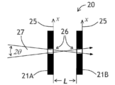
[0038]
도 2a 및 도 2b를 참조하면, 광학 필터(20)(도 2a)는 아래에서 설명되는 바와 같이 제공될 수 있다. 예를 들어, 광학 필터(20)는 광학 빔(23)의 광학 경로(22)에서 거리 L만큼 분리되는 순차적으로 배치되는 상류(21A) 및 하류(21B) 측면적 가변 밴드패스 광학 필터들을 포함할 수 있다. 도 2b에 도시되는 바와 같이, 상류(21A) 및 하류(21B) 필터들 각각은 χ-축들에 의해 표현되는 공통 제 1 방향(25)을 따라 상호 조정되는 방식으로 변화하는 밴드패스 중심 파장(![]()
![]()
![]()
![]()
![]()
![]()
![]()
![]()
![]()
![]()
![]()
![]()
![]()
![]()
![]()
![]()
[0039]
광학 필터(20)의 구성은 광학 빔(23)의 콜리메이션의 정도에 대한 광학 필터(20)의 스펙트럼 선택성의 의존도가 광학 빔(23)의 콜리메이션의 정도에 대한 하류 필터(21B)의 스펙트럼 선택성의 대응하는 의존도에 비해 줄어드는 것을 가능하게 할 수 있다. 광학 필터(20)의 이러한 성능 향상은 도 2c를 참조함으로써 이해될 수 있는 공간 필터링 효과로부터 발생할 수 있다. 파장(![]()
![]()
![]()
![]()
![]()
![]()
![]()
![]()
![]()
![]()
[0040]
도 2a의 광학 필터(20)의 동작은 측단면뷰에서 광학 필터(20)를 도시하는 도 3을 참조함으로써 추가로 설명될 수 있다. 도 3에서, 제 1 방향(25)은 수평적일 수 있고, 중심 파장(![]()
![]()
![]()
![]()
[0041]
![]()
![]()
[0042]
여기서, ![]()
![]()
![]()
![]()
![]()
![]()
![]()
![]()
[0043]
도 3의 예에서, 상류(21A) 및 하류(21B) 필터들은, 하류 필터(21B)의 레퍼런스 밴드패스 중심 파장(![]()
![]()
![]()
![]()
![]()
![]()
![]()
![]()
![]()
![]()
![]()
![]()
![]()
![]()
[0044]
도 3에 도시되는 기하학 구조에서, 좌측 주변 광선(31L)은 위치(![]()
![]()
![]()
![]()
![]()
![]()
![]()
![]()
![]()
![]()
![]()
![]()
![]()
![]()
![]()
![]()
![]()
![]()
![]()
![]()
[0045]
작은 각들 ![]()
![]()
[0046]
![]()
![]()
[0047]
![]()
![]()
[0048] 상류(21A) 및 하류(21B) 필터들 사이의 공간이 굴절 인덱스 n을 가지는 투명한 매체로 채워지는 경우, 수식 (3)은 [0048] When the space between the upstream (21A) and downstream (21B) filters is filled with a transparent medium having a refractive index n , Equation (3) is
[0048]
![]()
![]()
[0050]
수식 (4)는 필터-간 거리 L 사이의 대략적 관계, 필터-간 갭의 굴절 인덱스 n, 상류 필터(21A)의 대역폭과 관련된 제 1 방향(25)에 따른 측면 거리 ![]()
![]()
![]()
![]()
![]()
![]()
![]()
![]()
![]()
![]()
![]()
![]()
[0051]
![]()
![]()
[0052]
여기서, neff는 상류 필터(21A)의 유효 굴절 인덱스를 표현한다.Here, n eff represents the effective refractive index of the
[0053]
도 2b에서는 상류(21A) 및 하류(21B) 측면적 가변 밴드패스 필터들이 상기 수식 (1)에 의해 정의되는 바와 같이 선형적 가변 밴드패스 중심 파장들(![]()
![]()
![]()
![]()
![]()
![]()
![]()
![]()
![]()
![]()
[0054]
더 양호한 전체 스루풋에 대해, 하류 필터(21B)의 대역폭에 대응하는, 제 1 방향(25)을 따라 대응하는 측면 거리 ![]()
![]()
![]()
![]()
![]()
![]()
[0055] 상류(21A) 및/또는 하류(21B) 필터들은 2개, 3개 또는 그 초과의 상이한 재료들을 포함하는 박막 레이어 스택을 포함할 수 있는데, 예를 들어, 하이-인덱스 및/또는 흡수 레이어들이 상류(21A) 및 하류(21B) 필터들 각각의 전체 두께를 감소시키는데 사용될 수 있다. 게다가, 상류(21A) 및/또는 하류(21B) 필터들은, 회절 격자들, 예를 들어, 서브-파장 격자들, 다이크로익 폴리머들 등을 포함할 수 있다.[0055] Upstream (21A) and/or downstream (21B) filters may comprise a thin layer stack comprising two, three or more different materials, e.g., high-index and/or absorbent layers upstream. It can be used to reduce the overall thickness of each of the (21A) and downstream (21B) filters. In addition, the upstream (21A) and/or downstream (21B) filters may include diffraction gratings, such as sub-wavelength gratings, dichroic polymers, and the like.
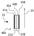
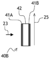
[0056]
도 4a를 참조하면, 광학 필터(40A)의 상류(21A) 및 하류(21B) 필터들은 연속적으로 접합(join)되는 각각의 기판들(42A 및 42B) 상에 증착되는 박막 웨지 간섭 코팅들(41A 및 41B)을 포함할 수 있다. 기판들(42A 및 42B)은 상류(41A) 및 하류(41B) 박막 웨지 간섭 코팅들 사이의 굴절 인덱스 n을 가지는 투명한 매체로서 기능할 수 있다. 도 4b를 참조하면, 단일 공통 기판(42)은 광학 필터(40B)에서 사용될 수 있고, 상류(41A) 및 하류(41B) 박막 웨지 간섭 코팅들은 공통 기판(42)의 반대 면들 상에 배치된다. 공통 기판(42)은 광학 필터(40C)의 상류(41A) 및 하류(41B) 박막 웨지 간섭 코팅들(필터들)이 서로에 대해 특정 각으로 배치되도록 도 4c에 도시되는 바와 같이 웨지될 수 있다. 이러한 경우, 거리 L은 제 1 방향(25)을 따라 변화할 수 있다. 거리 L 변화는 상류(41A) 및 하류(41B) 필터들 사이의 스펙트럼 슬로프 미스매치뿐만 아니라, 상류(41A) 및 하류(41B) 필터들 사이의 스펙트럼 라인폭 차가 관리되도록 도울 수 있다. 그 목적을 위해서, 굴절 인덱스 n은 또한 일정하거나 또는 변화하는 거리 L에서 제 1 방향(25)을 따라 변화할 수 있다.Referring to Figure 4a, the upstream (21A) and downstream (21B) filters of the optical filter (40A) is a thin film wedge interference coating deposited on each of the substrates (42A and 42B) to be joined in succession They may include 41A and 41B.
[0057]
도 4d는 상류(41A) 및 하류(41B) 박막 웨지 간섭 코팅들이 떨어져 이격된 관계에서 배치되는 서로 대면하고 있을 수 있는 광학 필터(40D)의 또 다른 구성을 예시한다. 도 4e의 광학 필터(40E)는 둘 다가 동일한 방향, 예를 들어, 이 경우, 광학 빔(23)을 향하는 박막 웨지 간섭 코팅들(41A 및 41B)을 포함하는 또 다른 실시예를 예시한다.[0057]
4D illustrates another configuration of an
[0058]
도 2a 및 도 4a 내지 도 4c를 추가로 참조하는 수식 (4)를 다시 참조하면, 값 L/n은 전형적으로 0.2mm보다 클 수 있다. 하나의 실시예에서, 값 L/n은 15mm보다 작을 수 있는데, 예를 들어, 0.2mm 내지 15mm일 수 있다. 거리 L은 실제 박막 코팅들, 예를 들어, 도 4a 내지 도 4c에서의 41A 및 41B 사이의 거리에 대응할 수 있으며, 기판들(42, 42A 및/또는 42B)이 박막 코팅들(41A 및 41B) 사이의 광학 경로(22)에 있는 경우, 이 기판들의 두께들을 포함할 수 있다는 것이 인식되어야 한다. 비-제한적 예시로서, 도 4b의 광학 필터(40B)에서, L은 기판(42)의 두께를 표현할 수 있고, n은 기판(42)의 굴절 인덱스를 표현할 수 있다.Referring again to Equation (4) with additional reference to FIGS. 2A and 4A to 4C, the value L / n may typically be greater than 0.2mm. In one embodiment, the value L / n may be less than 15 mm, for example, 0.2 mm to 15 mm. The distance L may correspond to the distance between the actual thin film coatings, for example 41A and 41B in FIGS. 4A to 4C, and the
[0059]
이제, 도 5a를 참조하면, 광학 필터(50A)는 도 2a의 광학 필터(20)와 유사할 수 있으며, 도 4a 내지 도 4e의 광학 필터들(40A 내지 40E)과 유사할 수 있다. 그러나, 도 5a의 광학 필터(50A)는 광학 경로(22)에 배치되는 어퍼처(51A)를 더 포함할 수 있다. 어퍼처(51A)는 제 1 방향(25)에서 변화하는 폭 d를 가질 수 있다. 어퍼처(51A)의 변화하는 폭 d의 하나의 기능은 광학 필터(5OA) 상에서의 광학 에너지 충돌의 양을 조정하는 것일 수 있고, 이는 상류(21A)/하류(21B) 필터들의 출력 송신의 크기의 파장 의존도, 및/또는 광검출기 어레이(도시되지 않음)의 스펙트럼 응답을 보상하는데 사용될 수 있다.[0059] Now, referring to FIG. 5A, the
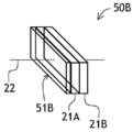
[0060]
보상 필터는 필터의 스펙트럼 응답 및/또는 광검출기(도시되지 않음)의 스펙트럼 응답의 더 정확한 제어를 위해서 이용될 수 있다. 도 5b를 참조하면, 광학 필터(50B)는 도 2a의 광학 필터(20)와 유사할 수 있으며, 도 4a 내지 도 4e의 광학 필터들(40A 내지 40E)과 유사할 수 있다. 스펙트럼 응답 평탄화 필터(51B)는 광학 필터(50B)의 스펙트럼 응답을 평탄화하기 위해서 광학 필터(50B)의 광학 경로(22)에 배치될 수 있다. 스펙트럼 평탄화 필터(50B)가 상류 필터(21A) 상에 배치되는 것으로 도 5b에 도시되지만, 스펙트럼 평탄화 필터(5OB)는 하류 필터(21B) 상에 그리고/또는 상류(21A) 및 하류(21B) 필터들 사이의 광학 경로(22)에 배치될 수 있다.[0060]
Compensation filters can be used for more precise control of the spectral response of the filter and/or of the photodetector (not shown). Referring to FIG. 5B, the
[0061]
이제, 도 5c를 참조하면, 광학 필터(50C)는 도 2a의 광학 필터(20)와 유사할 수 있으며, 도 4a 내지 도 4e의 광학 필터들(40A 내지 40E)과 유사할 수 있다. 그러나, 도 5c의 광학 필터(50C)는 광학 경로(22)에서 추가 필터(21C)를 더 포함할 수 있다. 추가 필터(21C)는 상류(21A) 및 하류(21B) 필터들의 밴드패스 중심 파장들을 통해 조정되는 방식으로 변화하는 밴드패스 중심 파장을 가질 수 있다. 추가 필터(21C)는 또한, 하이 패스 또는 로우 패스 측면적 가변 필터, 분산적 엘리먼트, 이를테면, 회절 격자, 스펙트럼으로의 코팅 및/또는 측면적 가변 흡수 등을 포함할 수 있다. 추가 필터(21C)의 기능은 유입 광의 입력 어퍼처수를 추가로 정의하는 것 및/또는 광학 필터(20)의 분해력을 추가로 향상시키는 것일 수 있다. 3개 초과의 측면적 가변 밴드패스 필터들(21A, 21B, ..., 21N) ― N은 임의의 정수를 표현함 ― 은 광학 필터(50C)에서 사용될 수 있다.[0061]
Now, referring to FIG. 5C, the
[0062]
도 2a를 추가로 참조하는 도 6a를 참조하면, 광학 분광계(60A)(도 6a)는 도 2a의 광학 필터(20) 및 하류 필터(21B)의 광학 경로(22) 하류에 배치되는 광검출기 어레이(61)를 포함할 수 있다. 광검출기 어레이(61)는 예를 들어, 광원(69)에 의해 발광되는 광학 빔(23)의 개별 스펙트럼 컴포넌트들의 광학 전력 레벨들을 검출하기 위해서 제 1 방향(25)을 따라 배치되는 픽셀들(62)을 가질 수 있다. 넓은 의미에서, "광원"이라는 용어는, 예를 들어, 흡수 측정들을 위한 실제 광원, 형광성 또는 스캐터링 샘플 등을 지칭할 수 있다. 예를 들어, 발광성 및/또는 스캐터링 샘플로부터 발생하는(originate) 광 빔(23)은 일반적으로 수렴(converging) 또는 발산(diverging) 광선들을 포함할 수 있다. 본원에서, "발산"이라는 용어는 광학 빔(23)을 포함하는 광선들이 동일한 단일 포인트로부터 발생한다는 것을 요구하지 않을 수 있다. 유사하게, "수렴"이라는 용어는 광학 빔(23)을 포함하는 광선들이 단일 포인트로 수렴하도록 요구하지 않을 수 있다. 도 2c 및 도 3을 참조하여 위에서 설명된 바와 같이, 상류(21A) 및 하류(21B) 밴드패스 측면적 가변 광학 필터들을 포함하는 광학 필터(20)의 듀얼-필터 구조는 광학 빔(23)의 콜리메이션의 정도에 대한 광학 분광계(60A)의 스펙트럼 선택성의 의존도의 감소를 초래할 수 있다. 다시 말해서, 상류 필터(21A)없이 단지 하류 필터(21B)만이 사용되었으면, 광학 분광계의 스펙트럼 선택성은 광학 빔(23)의 콜리메이션의 정도에 훨씬 더 의존할 수 있어서, 스펙트럼 선택성의 전반적 악화를 초래한다.[0062]
Referring to FIG. 6A with further reference to FIG. 2A, an
[0063]
광검출기 어레이(61)는 하류 필터(21B)와 직접 접촉할 수 있다. 광검출기 어레이(61)는 캡슐화(63)를 형성하도록 포팅(potting) 재료로 채워질 수 있다. 캡슐화(63)의 하나의 기능은 광학 필터(20)의 하류 필터(21B)의 클리어 어퍼처(64)를 가리지(obscure) 않으면서 광검출기 어레이(61)의 전자적 그리고/또는 열적 절연을 제공하는 것일 수 있다. 캡슐화(63)의 또 다른 기능은 충격, 습도 등으로부터 상류(21A) 및 하류(21B)의 에지들을 보호하는 것일 수 있다.[0063]
The
[0064]
도 2a 및 도 6a를 추가로 참조하는 도 6b를 참조하면, 광학 분광계(60B)(도 6b)는 도 2a의 광학 필터(20) 및 하류 필터(21B)의 광학 경로(22) 하류에 배치되는 광검출기 어레이(61)를 포함할 수 있다. 광학 분광계(60B)는 광학 빔(23)을 입력하기 위한, 광학 경로(22)에 배치되는 윈도우(67)를 가지는 인클로저(66)를 더 포함할 수 있다. 도시되는 실시예에서, 윈도우(67)는 상류 필터(21A)를 포함할 수 있고, 상류(21A) 및 하류(21B) 필터들은 갭(65), 예를 들어, 에어 갭에 의해 분리된다. 하류 필터(21B)는 광검출기 어레이(61) 바로 위에 실장될 수 있다. 하나의 실시예에서, 작은 갭 ― 예를 들어, 2mm보다 작음 ― 은 하류 필터(21B)와 광검출기 어레이(61) 사이에 존재할 수 있다.[0064]
6B with further reference to FIGS. 2A and 6A, an
[0065]
갭(65)은 광검출기 어레이(61)가 인클로저(66)로부터 열적으로 커플링해제되게 할 수 있고, 이는 결국 선택적 열전 쿨러(68)에 의해 광검출기 어레이(61)의 딥 쿨링을 가능하게 한다. 인클로저(66)는 더 양호한 신뢰성 및 환경적 안정성을 위해서 불활성 가스로 채워지고 그리고/또는 용봉될(hermetically sealed) 수 있다. 포커싱 엘리먼트(도시되지 않음)는 광검출기 어레이(61) 상에 광학 빔(23)을 포커싱하기 위해서 하류 필터(21B)와 광검출기 어레이(61) 사이의 광학 경로(22)에 제공될 수 있다. 광검출기 어레이(61) 이외의 센서가 사용될 수 있다. 비-제한적 예로서, 광검출기는 제 1 방향(25)에서 광학 필터(20)와 관련하여 변경될 수 있다.[0065]
The
[0066]
하류 필터(21B)의 실장 옵션들은 광검출기 어레이(61) 바로 위에 하류 필터(21B)의 박막 구조를 증착하는 것을 포함할 수 있다. 비-제한적 예로서, 도 7a 및 도 7b에서, 하류 필터(21B)는 광검출기 어레이(61)의 픽셀면(pixel side)(61A) 상에 증착될 수 있다. 일부 실시예들에서, 하류 필터(21B)는 2개의 차단 필터 섹션들(71) 및 2개의 차단 필터 섹션들(71) 사이의 밴드패스 필터 섹션(72)을 포함하는 웨지 박막 필터일 수 있다.[0066]
Mounting options of the
[0067]
구체적으로 도 7b에서, 광-흡수 마스크(73)는 미광으로부터 개별 픽셀들(62)을 보호하기 위해서 개별 픽셀들(62) 사이에 배치될 수 있다. 도 7c에서, 대안적 실장 옵션이 예시된다: 하류 필터(21B)가 광검출기 어레이(61)의 후면(61B) 상에 배치될 수 있다. 물론, 이 실장 옵션은 광검출기 어레이(61)의 기판(61C)이 광학 빔(23)에 투명하도록 요구할 수 있다. 유리하게, 후면-실장( back-mounting)은 드라이버 회로 칩(74)이 광검출기 어레이(61)의 픽셀면(61A)에 본딩된 플립-칩이 되게 할 수 있다. 도 7d를 참조하면, 하류 필터(21B)는, 예를 들어, 그루브들(76)로 주입되는 흑색 충전 재료(75)를 제공함으로써, 예를 들어, 복수의 병렬 그루브들(76)을 에칭함으로써 세그먼트화될 수 있고, 이것의 포지션은 광-흡수 마스크(73)의 바들(77)을 통해 조정될 수 있다.[0067]
Specifically, in FIG. 7B, the light-absorbing
[0068]
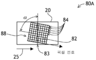
도 6a 및 도 6b를 추가로 참조하는 도 8a를 참조하면, 분광계(80A)는 부분적 평면뷰에 도시된다. 분광계(80A)는 분광계들(도 6a의 60A 및 도 6b의 60B)과 유사할 수 있다. 그러나, 분광계(도 8a의 80A)는 복수의 개별 광검출기 픽셀들(82)을 가지는 2D(two-dimensional) 광검출기 어레이(88)를 포함할 수 있다. 2D 광검출기 어레이(88)는, 단색 조명 시 스펙트럼 라인(83)이 2D 광검출기 어레이(88)의 픽셀들(82)의 행들(84)에 대해 각 α로 광검출기 어레이(31) 상에 형성되도록, 광학 필터(20)의 픽셀들(82)의 행들(84)에 관하여 예각 α만큼 회전 또는 클럭킹(clock)될 수 있다. 도 8a를 추가로 참조하는 도 8b를 참조하면, 각 α만큼의 회전 또는 클럭킹은 2D 광검출기 어레이(88)의 픽셀들(82)의 상이한 행들(84) 상의 광학 전력 밀도 분포들(85)이 서로로부터 오프셋되게 할 수 있다. 이러한 방식으로, 하나의 스펙트럼 대신에, 복수의 오프셋 스펙트럼들이 획득될 수 있고, 스펙트럼 분해능 및 파장 정확성이 증가하는 것을 가능하게 한다. 신호 대 잡음비는 또한, 예를 들어, 개별 광학 전력 밀도 분포들(85)을 디콘볼루팅(deconvoluting) 및 평균화함으로써 개선될 수 있다.[0068] Referring to FIG. 8A with further reference to FIGS. 6A and 6B,
[0069]
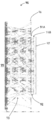
이제, 도 8c를 참조하면, 분광계(80C)는 도 8a의 분광계(80A)의 변형일 수 있다. 도 8c의 분광계(80C)는 또한, 2D 광검출기 어레이(88)를 포함할 수 있다. 도 8c에서, 2D 광검출기 어레이(88)는 도 8a에 도시되는 바와 같이 기울어질 수 있거나 또는 기울어지지 않을 수 있다. 도 8c의 분광계(80C)는, 즉, 광학 빔(23)의 광학 경로(22)에 횡단적인 제 1 방향(25)을 따라 상호 조정되는 방식으로 점차적으로 변화하는 밴드패스 중심 파장들을 가지는 도 2a의 광학 필터(20)의 대응하는 상류(21A) 및 하류(21B) 필터들과 유사한 상류(81A) 및 하류(81B) 필터들을 더 포함할 수 있다. 도 8c에서, 상류(81A) 및 하류(81B) 필터들 각각은 제 1 방향(25)과 수직인 제 2 방향(87)에서 나란히 배열되는 복수의 세그먼트들(89A-1, 89A-2, 89A-3(상류 필터(81A))... 및 89B-1, 89B-2, 89B-3(하류 필터(81B))를 포함할 수 있다. 상류 필터(81A)의 각각의 세그먼트(89A-1, 89A-2, 89A-3...)는 전용 파장 구역에서의 동작을 위해서 하류 필터(81B)의 세그먼트들(89B-1, 89B-2, 89B-3) 중 하나에 대응한다. 비-제한적 예로서, 제 1 쌍의 세그먼트들(89A-1 및 89B-1)은 1000nm 내지 1200nm의 파장 범위에서의 동작들을 위해서 구성될 수 있고, 제 2 쌍의 세그먼트들(89A-2 및 89B-2)은 1200nm 내지 1400nm의 파장 범위에서의 동작을 위해서 구성될 수 있고, 제 3 쌍의 세그먼트들(89A-3 및 89B-3)은 1400nm 내지 1600nm의 파장 범위에서의 동작을 위해서 구성될 수 있는 식이다. 파장 범위들은 인접할 필요가 없을 수 있다. 예를 들어, 다수의 세그먼트들은 가시 파장들 또는 근 IR(infrared), 중 IR, UV(ultraviolet) 및 심지어 연질 X-광선과 같은 다른 파장 구역들에 대해 제공될 수 있다. 따라서, 분광계(80C)는 멀티-스펙트럼 감지 및/또는 멀티-스펙트럼 이미징 애플리케이션들에 적합할 수 있다. 이 멀티-스펙트럼 감지/이미징 애플리케이션들은 당업자들에 의해 인식되는 바와 같이, 적합한 기판 및 코팅 재료들을 요구할 수 있다.[0069]
Referring now to FIG. 8C,
[0070]
도 2a를 다시 참조하면, 광학 경로(22)를 따라 전파되는 광학 빔(23)의 스펙트럼을 획득하기 위한 방법은 거리 L만큼 분리되는 상류(21A) 및 하류(21B) 측면적 가변 밴드패스 광학 필터들을 가지는 광학 필터(20)를 통해 광학 빔(23)을 필터링하는 단계를 포함할 수 있다. 도 2b에 예시되는 바와 같이, 상류(21A) 및 하류(21B) 필터들 각각은 광학 경로(22)에 횡단적인 공통 제 1 방향(25)을 따라 상호 조정되는 방식(예를 들어, 24A, 24B)으로 점차적으로 변화하는 밴드패스 중심 파장(![]()
![]()
[0071]
방법의 다음의 단계에서, 광학 전력 분포는 하류 필터(21B)의 하류에서 제 1 방향(25)을 따라 검출될 수 있다. 예를 들어, 도 6a, 도 6b 및 도 8a를 다시 참조하면, 광검출기 어레이(61)(도 6a, 6b) 또는 2D 광검출기 어레이(88)(도 8a)는 하류 필터(21B)의 하류에 배치될 수 있고, 광학 전력 분포는 광검출기 어레이들(61 또는 88)을 사용하여 검출될 수 있다. 도 6a 및 도 7a 내지 도 7c를 다시 참조하면, 하류 필터(21B)는 하류 필터(60A)의 클리어 어퍼처(64)를 가리지 않으면서 광검출기 어레이(61)를 절연하도록 포팅 재료로 채워질 수 있는 광검출기 어레이(61) 바로 위에 배치, 예를 들어, 증착될 수 있다.[0071]
In the next step of the method, the optical power distribution can be detected along the
[0072]
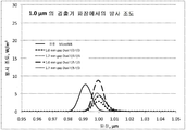
일부 실시예들에서, 광선-추적 시뮬레이션은 도 2a의 광학 필터(20A) 및 본 개시 내용의 유사한 필터들의 성능을 검증하도록 수행될 수 있다. 도 9a 및 도 9b를 참조하면, 광선-추적 모델(90)은 램버시안 광원(99), 직사각형 어퍼처(96), 상류 측면적 가변 밴드패스 필터(91A), 길이 L을 가지는 투명한 스페이서(92), 하류 측면적 가변 밴드패스 필터(91B) 및 광검출기(97)를 순서대로 포함할 수 있다. 광선-추적 모델(90)의 입력 파라미터들은 아래의 표 1에 요약된다. 예를 들어, 광선들(93)은 반복가능한 결과들을 획득하기 위해서 충분한 수로 추적되었다. 각각의 광선(93)은 미리 정의된 파장을 가졌으며, 미리 정의된 광학 전력을 전달하였다. 광학 전력 판독들은 도 2a에서 제 1 방향(25)에 대응하는 분산 방향(95)을 따라 정렬되는 광검출기(97)의 빈들에 누적되었다. 상수 파라미터들은 램버시안 광원(99)으로부터 3mm의 어퍼처(96)로의 거리; 6.6mm x 0.25mm의 광검출기(97)의 크기; 및 838과 동일한 광검출기(97)의 빈들의 수 또는 픽셀들을 포함하였다. 변화되는 파라미터들은 상류(91A) 및 하류(91B) 측면적 가변 밴드패스 필터들의 % 단위의 대역폭 및 F/# 단위의 NA, 및 투명한 스페이서(92)의 두께를 포함하였다. 램버시안 광원(99)은 0.95㎛; 1.05㎛; 1.15㎛; 1.25㎛; 1.35㎛; 1.45㎛; 1.55㎛; 및 1.65㎛의 8개의 파장들에서 광을 발광하였다.[0072]
In some embodiments, ray-trace simulation may be performed to verify the performance of optical filter 20A of FIG. 2A and similar filters of the present disclosure. 9A and 9B, the ray-tracking
[0073] [0073]

[0074]
도 10을 참조하면, 시뮬레이션 결과들은 도 9a, 도 9b의 광학 광선-추적 모델(90)의 광검출기(97)의 빈들에 누적되는 광학 전력 분포들의 형태로 제시된다. 상위 그래프(100)는 "레퍼런스 모델" ― 광 콜리메이션에 대한 테이퍼링된 광 파이프를 가지는 시뮬레이팅된 상업적으로 이용가능한 MicroNIR™ 분광계 ― 에 대응한다. 도면들(101 내지 104)은 위의 표 1의 레퍼런스 모델들 1 내지 4 각각에 대응한다.[0074]
Referring to FIG. 10, simulation results are presented in the form of optical power distributions accumulated in bins of the
[0075]
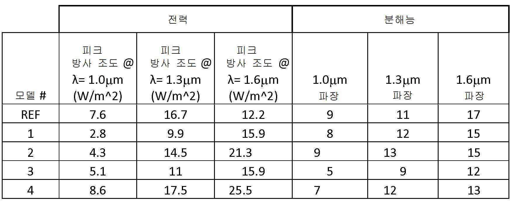
도 11a, 도 11b 및 도 11c를 참조하면, 더 상세한 스펙트럼 성능이 1.0㎛; 1.3㎛; 및 1.6㎛의 각각의 파장들에서 시뮬레이팅될 수 있다. 모델들 1 내지 4가 훨씬 더 양호한 파장 정확성 및 유사한 스펙트럼 선택성을 예시하였다는 것이 인식되어야 한다. 도 12를 참조하면, 모델들 1 및 3의 분해력은 0.12㎛ 분리에서의 1.3㎛에서 듀얼 스펙트럼 라인을 사용하여 설명된다. 도 10, 도 11a 내지 도 11c 및 도 12에 도시되는 결과들에서, 모델들 1 내지 4는 테이퍼링된 광 파이프 또는 또 다른 광 콜리메이팅 엘리먼트들을 가지지 않았지만, 모델들 1 내지 4는 수용가능한 스펙트럼 대역폭을 도시하였다는 것이 인식되어야 한다. 테이퍼링된 광 파이프가 레퍼런스 모델로부터 배제되는 경우, 레퍼런스 모델의 스펙트럼 선택성은 수용가능하게 낮아진다.[0075]
11A, 11B and 11C, a more detailed spectral performance is 1.0 μm; 1.3 μm; And at respective wavelengths of 1.6 μm. It should be appreciated that Models 1-4 demonstrated much better wavelength accuracy and similar spectral selectivity. Referring to Fig. 12, the resolution of
[0076] 아래의 표 2는 모델들 1-4의 획득된 시뮬레이팅된 성능을 요약한다.[0076] Table 2 below summarizes the obtained simulated performance of Models 1-4.
[0077] [0077]
[0078]
도 6a의 광학 필터(60A)의 성능은 시뮬레이션에 의해 검증될 수 있다. 어퍼처 부트, 테이퍼링된 광 파이프, InGaAs 다이오드 어레이를 포함하는 표준 MicroNIR™ 분광계의 성능은 또한, 레퍼런스를 제공하도록 시뮬레이팅되었다. 도 13을 참조하면, 표준 MicroNIR™ 분광계 성능은 0.1㎛만큼 분리되는 0.9㎛와 1.7㎛ 사이의 멀티-파장 신호의 점선 스펙트럼(131)에 의해 표현될 수 있다. 실선 스펙트럼(132)은 분광계(60A)의 시뮬레이팅된 성능을 예시하고, 이는 광학을 형상화하는 임의의 콜리메이팅 또는 광이 없다. 스펙트럼 피크들 사이의 일부 미광은 코팅으로 간주되며, 이는 사용되는 파장 범위에 대해 최적화되지 않는다. 둘 다의 측정들에 대한 조명 조건들이 동일하였다.[0078]
The performance of the
[0079]
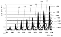
도 14를 참조하면, 멀티-파장 스펙트럼들(140A - 140G)은 0.2mm 내지 30mm의 범위를 가지는 필터-간 거리 L의 상이한 값들에서 도 2a의 광학 필터(20)를 사용하여 시뮬레이션에 의해 획득되었다. 필터-간 거리 L이 증가함에 따라, 필터 스루풋은 감소되고, 미광(141)의 대역-외 제거가 개선된다는 것이 인식되어야 한다. 이것은, 필터-간 거리 L이 증가함에 따라 광학 필터(20)(도 2c, 도 3)의 수광콘(20)은 감소되기 때문에, 발생할 수 있다.14,
[0080]
도 15a를 참조하면, 분광계(150)는 윈도우(152)를 가지는 하우징(151)을 포함할 수 있다. 광학 필터(153)는 하류 측면적 가변 필터(도시되지 않음)로부터 물리적으로 2.08mm 이격되는 상류 측면적 가변 필터(도시되지 않음)를 포함할 수 있다. 상류 필터(도 15a에 도시되지 않음)는 1300nm 및 900nm 내지 1700nm 범위의 중심 파장의 1.3%의 패스밴드를 가질 수 있다. 광학 필터(153)의 상위에 있는 상류 필터는 2mm의 폭, 8mm의 길이 및 1.1mm의 두께를 가질 수 있다. 하류 필터는 1300nm 및 900nm 내지 1700nm 범위의 중심 파장의 0.8%의 패스밴드를 가질 수 있다. 하류 필터는 1.4mm의 폭, 7.4mm의 길이 및 1.5mm의 두께를 가질 수 있다. 표준 128-픽셀 검출기 어레이(도시되지 않음)는 하류 필터로부터 80 마이크로미터 떨어져 배치되었다. 전자 드라이버(154)는 검출기 어레이를 드라이버(driver)하는데 사용되었다.[0080]
Referring to FIG. 15A, the
[0081]
광학 필터(153) 및 전자 드라이버(154)는 또한, 실선들(155)로 상징적으로 도시되는 바와 같은 도 15a의 확대뷰인 도 15b에 도시될 수 있다. 도 15b에 도시되는 바와 같이, 5mm의 길이를 가지는 스케일 바(156)가 사용될 수 있다.[0081]
The
[0082]
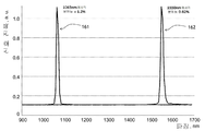
이제, 도 16을 참조하면, 발광 스펙트럼(161 및 162)은 도 15a 및 도 15b의 분광계(150)를 사용하여 획득되었다. 1064nm 및 1551nm의 파장들에서의 2개의 레이저원들의 발광은, 차례로, 스위칭가능한 발광 파장을 가지는 램버시안 조명원을 생성하기 위해서 적분구로 지향되었다. 광검출기 어레이의 적분 시간들은 조정되어서, 둘 다의 스펙트럼들이 동일한 피크 진폭을 가졌는데, 그 이유는 각각의 레이저가 상이한 전력 출력 레벨들을 가졌기 때문이다. 어떠한 다른 스펙트럼 또는 공간 필터들도 이 측정들을 위해서 사용되지 않았다. 적분구는 25mm 포트를 가졌으며, 상류 필터로부터 35mm 떨어져 배치되었다. 둘 다의 스펙트럼들(161 및 162)에서, 파장 분해능은 광검출기 어레이의 픽셀 구조에 의해 제한될 수 있다. 1065nm에서의 쓸모있는(instrumental) 3dB 대역폭은 ![]()
![]()
![]()
![]()
[0083]
도 17을 참조하면, 송신 스펙트럼들(171 및 172)은 할로겐 램프의 전방에 배치되는 NIST 추적가능한 송신 레퍼런스(이러한 경우, 조류 도핑된 유리 레퍼런스 WCT2065-025)를 사용하여 획득되었다. 실선으로 도시되는 제 1 스펙트럼(171)은 도 15a 및 도 15b의 분광계(150)를 사용하여 획득되었다. 제 2 스펙트럼(172)(점선으로 도시됨)은 미국 California주 Milpitas시의 JDS Uniphase Corporation에 의해 제조되는 표준 MicroNIR1700 분광계를 사용하여 획득되었다.[0083]
Referring to FIG. 17,
[0084]
둘 다의 경우들에서, 어두운-상태 레퍼런스 스펙트럼들은 광원을 차단함으로써 수집되었다. 밝은-상태 레퍼런스 스펙트럼들은 광학 경로로부터의 도핑된 유리 레퍼런스를 제거함으로써 수집되었다. 제 1 스펙트럼(171)이 제 2 스펙트럼(172)과 밀접하게 상관된다는 것이 보여질 수 있다. 제 1 스펙트럼(171)은 도 15a 및 도 15b의 분광계(150)의 전방에 배치되는 1mm 폭 어퍼처를 통해 획득되었다. 어퍼처 없이, 분해능은 약간 감소되었지만, 통합(데이터 수집) 시간은 3배 감소되었다.[0084]
In both cases, dark-state reference spectra were collected by blocking the light source. Bright-state reference spectra were collected by removing the doped glass reference from the optical path. It can be seen that the
[0085] 앞의 명세서에서, 다양한 실시예들은 첨부한 도면들을 참조하여 설명되었다, 그러나, 다음의 청구항들에서 기술되는 바와 같은 본 개시 내용의 더 넓은 범위로부터 벗어나지 않고 그것에 대해 다양한 수정들 및 변화들이 이루어질 수 있다는 것 그리고 추가 실시예들이 구현될 수 있다는 것이 자명할 것이다. 따라서, 명세서 및 도면들은, 제한적 의미라기 보다는 예시적인 것으로 간주될 것이다.[0085] In the preceding specification, various embodiments have been described with reference to the accompanying drawings, however, it is understood that various modifications and changes may be made thereto without departing from the broader scope of the disclosure as set forth in the following claims. And it will be apparent that further embodiments may be implemented. Accordingly, the specification and drawings will be regarded as illustrative rather than restrictive.
[0086] 이러한 점에서, 위에서 설명되는 바와 같은 본 개시 내용에 따른 광학 필터 및 분광계는 입력 데이터의 프로세싱 및 출력 데이터의 생성을 다소 수반할 수 있다는 점이 주목되어야 한다. 이러한 입력 데이터 프로세싱 및 출력 데이터 생성은 하드웨어 또는 소프트웨어로 구현될 수 있다. 예를 들어, 특정 전자 컴포넌트들은 위의 설명된 바와 같은 본 개시 내용에 따라 광학 필터 및/또는 분광계를 제공하는 것과 연관된 기능들을 구현하기 위한 프로세서, 모듈 또는 유사한 관련 회로에서 이용될 수 있다. 대안적으로, 명령들에 따라 동작하는 하나 또는 그 초과의 프로세서들은 위에서 설명되는 바와 같은 본 개시 내용과 연관된 기능들을 구현할 수 있다. 그런 경우라면, 그것은 이러한 명령들이 하나 또는 그 초과의 프로세서 판독가능한 저장 매체들(예를 들어, 자기 디스크 또는 다른 저장 매체) 상에 저장되거나, 또는 하나 또는 그 초과의 반송파들에서 구현되는 하나 또는 그 초과의 신호들을 통해 하나 또는 그 초과의 프로세서들에 송신될 수 있다는 본 개시 내용의 범위 내에 있다.[0086] In this regard, it should be noted that optical filters and spectrometers according to the present disclosure as described above may somewhat involve processing of input data and generation of output data. This input data processing and output data generation can be implemented in hardware or software. For example, certain electronic components may be used in a processor, module, or similar related circuit to implement functions associated with providing an optical filter and/or spectrometer in accordance with the present disclosure as described above. Alternatively, one or more processors operating in accordance with the instructions may implement functions associated with the present disclosure as described above. If so, it may be that such instructions are stored on one or more processor-readable storage media (e.g., magnetic disk or other storage media), or implemented on one or more carriers. It is within the scope of this disclosure that more signals may be transmitted to one or more processors.
[0087] 본 개시 내용은 본원에서 설명되는 특정 실시예들에 의한 범위 내에 제한되지 않을 것이다. 실제로, 본원에서 설명되는 것들과 더불어, 다른 다양한 실시예들 및 수정들은 위의 설명 및 첨부한 도면들로부터 당업자들에게 명백해질 것이다. 따라서, 이러한 다른 실시예들 및 수정들은 본 개시 내용의 범위 내에 속하는 것으로 의도된다. 추가로, 본 개시 내용은 특정 목적을 위해서 특정 환경에서 특정 구현의 문맥으로 본원에서 설명되었지만, 당업자들은 많은 목적들을 위해서 많은 환경들에 그것의 유용성이 제한되지 않고, 본 개시 내용이 이들에서 유익하게 구현될 수 있다는 것을 인식할 것이다. 따라서, 아래에서 기술되는 청구항들은 본원에서 설명되는 바와 같은 본 개시 내용의 전체 넓이 및 사상을 고려하여 해석되어야 한다.[0087] The present disclosure will not be limited within the scope of the specific embodiments described herein. Indeed, in addition to those described herein, various other embodiments and modifications will become apparent to those skilled in the art from the above description and the accompanying drawings. Accordingly, these other embodiments and modifications are intended to be within the scope of this disclosure. In addition, although the present disclosure has been described herein in the context of a specific implementation in a specific environment for a specific purpose, those skilled in the art are not limited in its usefulness to many environments for many purposes, and the disclosure will benefit It will be appreciated that it can be implemented. Accordingly, the claims set forth below should be interpreted in consideration of the overall breadth and spirit of the present disclosure as described herein.
Claims (20)
상기 광학 필터의 매체 상에 증착되는 제 1 박막 웨지 간섭 코팅(thin film wedged interference coating); 및
상기 광학 필터의 상기 매체 상에 증착되는 제 2 박막 웨지 간섭 코팅을 포함하고,
상기 제 1 박막 웨지 간섭 코팅은 상기 매체의 제 1 측면(side) 상에 증착되고 그리고 상기 제 2 박막 웨지 간섭 코팅은 광 빔의 광학 경로에 대하여 상기 매체의 반대쪽(opposite) 제 2 측면 상에 증착되거나, 또는
상기 매체는 상기 제 1 박막 웨지 간섭 코팅 및 상기 제 2 박막 웨지 간섭 코팅 사이에 위치되고,
상기 매체는 단일 공통 기판인, 광학 필터.As an optical filter,
A first thin film wedged interference coating deposited on the medium of the optical filter; And
A second thin film wedge interference coating deposited on the medium of the optical filter,
The first thin film wedge interference coating is deposited on a first side of the medium and the second thin film wedge interference coating is deposited on a second side of the medium opposite to the optical path of the light beam. Or
The medium is positioned between the first thin film wedge interference coating and the second thin film wedge interference coating,
Wherein the medium is a single common substrate.
상기 제 1 박막 웨지 간섭 코팅은, 상류(upstream) 박막 웨지 간섭 코팅인, 광학 필터.The method of claim 1,
Wherein the first thin film wedge interference coating is an upstream thin film wedge interference coating.
상기 광학 필터는 상류 필터 및 하류 필터를 포함하고,
상기 상류 필터는 상기 제 1 박막 웨지 간섭 코팅을 포함하고,
상기 하류 필터는 상기 제 2 박막 웨지 간섭 코팅을 포함하는, 광학 필터.The method of claim 1,
The optical filter comprises an upstream filter and a downstream filter,
The upstream filter comprises the first thin film wedge interference coating,
Wherein the downstream filter comprises the second thin film wedge interference coating.
상기 매체는 상기 제 1 박막 웨지 간섭 코팅 및 상기 제 2 박막 웨지 간섭 코팅 사이에서 굴절 인덱스 n을 갖는 투명 매체인, 광학 필터.The method of claim 1,
Wherein the medium is a transparent medium having a refractive index n between the first thin film wedge interference coating and the second thin film wedge interference coating.
상기 제 1 박막 웨지 간섭 코팅 및 상기 제 2 박막 웨지 간섭 코팅 사이의 거리 L는 변화하는, 광학 필터.The method of claim 1,
The optical filter, wherein the distance L between the first thin film wedge interference coating and the second thin film wedge interference coating varies.
상기 광학 필터의 기판 상에 증착되는 제 1 웨지 간섭 코팅(wedged interference coating); 및
상기 광학 필터의 상기 기판 상에 증착되는 제 2 웨지 간섭 코팅을 포함하고,
상기 제 1 웨지 간섭 코팅은 상기 기판의 제 1 측면 상에 증착되고 그리고 상기 제 2 웨지 간섭 코팅은 상기 기판의 반대쪽 제 2 측면 상에 증착되고,
상기 기판은 단일 공통 기판인, 광학 필터.As an optical filter,
A first wedge interference coating deposited on the substrate of the optical filter; And
A second wedge interference coating deposited on the substrate of the optical filter,
The first wedge interference coating is deposited on a first side of the substrate and the second wedge interference coating is deposited on a second side opposite of the substrate,
Wherein the substrate is a single common substrate.
상기 광학 필터는 상류 필터 및 하류 필터를 포함하고,
상기 상류 필터는 상기 제 1 웨지 간섭 코팅을 포함하고,
상기 하류 필터는 상기 제 2 웨지 간섭 코팅을 포함하는, 광학 필터.The method of claim 6,
The optical filter comprises an upstream filter and a downstream filter,
The upstream filter comprises the first wedge interference coating,
Wherein the downstream filter comprises the second wedge interference coating.
상기 제 1 웨지 간섭 코팅 및 상기 제 2 웨지 간섭 코팅 사이에 공간이 존재하는, 광학 필터.The method of claim 6,
An optical filter, wherein there is a space between the first wedge interference coating and the second wedge interference coating.
광학 경로에 배치되는 어퍼처(aperture)를 더 포함하는, 광학 필터.The method of claim 6,
The optical filter, further comprising an aperture disposed in the optical path.
상기 어퍼처의 폭은 변화하는, 광학 필터.The method of claim 9,
The optical filter, wherein the width of the aperture changes.
광학 빔을 필터링하는 단계를 포함하고,
상기 광학 빔은 광학 필터를 사용하여 필터링되고,
상기 광학 필터는,
상기 광학 필터의 기판 상에 증착되는 제 1 박막 웨지 간섭 코팅; 및
상기 광학 필터의 상기 기판 상에 증착되는 제 2 박막 웨지 간섭 코팅을 포함하고,
상기 제 1 박막 웨지 간섭 코팅은 상기 기판의 제 1 측면 상에 증착되고 그리고 상기 제 2 박막 웨지 간섭 코팅은 광 빔의 광학 경로에 대하여 상기 기판의 반대쪽 제 2 측면 상에 증착되거나, 또는
상기 기판는 상기 제 1 박막 웨지 간섭 코팅 및 상기 제 2 박막 웨지 간섭 코팅 사이에 위치되고,
상기 기판은 단일 공통 기판인, 방법.As a method,
Filtering the optical beam,
The optical beam is filtered using an optical filter,
The optical filter,
A first thin film wedge interference coating deposited on the substrate of the optical filter; And
A second thin film wedge interference coating deposited on the substrate of the optical filter,
The first thin film wedge interference coating is deposited on a first side of the substrate and the second thin film wedge interference coating is deposited on a second side opposite of the substrate with respect to the optical path of the light beam, or
The substrate is positioned between the first thin film wedge interference coating and the second thin film wedge interference coating,
Wherein the substrate is a single common substrate.
상기 기판은 상기 제 1 박막 웨지 간섭 코팅 및 상기 제 2 박막 웨지 간섭 코팅 사이에서 굴절 인덱스 n을 갖는 투명 매체를 포함하는, 방법.The method of claim 11,
Wherein the substrate comprises a transparent medium having a refractive index n between the first thin film wedge interference coating and the second thin film wedge interference coating.
상기 제 1 박막 웨지 간섭 코팅 및 상기 제 2 박막 웨지 간섭 코팅 사이에 공간이 존재하는, 방법.The method of claim 11,
A method, wherein a space exists between the first thin film wedge interference coating and the second thin film wedge interference coating.
상기 광학 필터는 상기 광학 경로에 배치되는 어퍼처를 더 포함하는, 방법.The method of claim 11,
The optical filter further comprising an aperture disposed in the optical path.
상기 제 1 박막 웨지 간섭 코팅 및 상기 제 2 박막 웨지 간섭 코팅 사이의 거리 L는 변화하는, 방법.The method of claim 11,
The method, wherein the distance L between the first thin film wedge interference coating and the second thin film wedge interference coating varies.
상기 제 1 박막 웨지 간섭 코팅은, 상류 박막 웨지 간섭 코팅인, 방법.The method of claim 11,
Wherein the first thin film wedge interference coating is an upstream thin film wedge interference coating.
상기 광학 필터는 상류 필터 및 하류 필터를 포함하고,
상기 상류 필터는 상기 제 1 박막 웨지 간섭 코팅을 포함하고,
상기 하류 필터는 상기 제 2 박막 웨지 간섭 코팅을 포함하는, 방법.The method of claim 11,
The optical filter comprises an upstream filter and a downstream filter,
The upstream filter comprises the first thin film wedge interference coating,
Wherein the downstream filter comprises the second thin film wedge interference coating.
상기 제 1 박막 웨지 간섭 코팅은 상기 제 2 박막 웨지 간섭 코팅에 대해 일정 각도로 배치되는, 광학 필터.The method of claim 1,
The optical filter, wherein the first thin film wedge interference coating is disposed at an angle with respect to the second thin film wedge interference coating.
상기 광학 경로에 배치되는 어퍼처를 더 포함하는, 광학 필터.The method of claim 1,
The optical filter further comprising an aperture disposed in the optical path.
상기 광학 필터는 상류 필터 및 하류 필터를 포함하고,
상기 상류 필터는 서브-파장 격자(sub-wavelength grating)를 포함하고,
상기 하류 필터는 다이크로익 폴리머(dichroic polymer)를 포함하는, 방법.The method of claim 11,
The optical filter comprises an upstream filter and a downstream filter,
The upstream filter includes a sub-wavelength grating,
Wherein the downstream filter comprises a dichroic polymer.
Applications Claiming Priority (4)
| Application Number | Priority Date | Filing Date | Title |
|---|---|---|---|
| US201461934547P | 2014-01-31 | 2014-01-31 | |
| US61/934,547 | 2014-01-31 | ||
| PCT/US2015/013415 WO2015116756A1 (en) | 2014-01-31 | 2015-01-29 | An optical filter and spectrometer |
| KR1020167022476A KR102197456B1 (en) | 2014-01-31 | 2015-01-29 | An optical filter and spectrometer |
Related Parent Applications (1)
| Application Number | Title | Priority Date | Filing Date |
|---|---|---|---|
| KR1020167022476A Division KR102197456B1 (en) | 2014-01-31 | 2015-01-29 | An optical filter and spectrometer |
Publications (2)
| Publication Number | Publication Date |
|---|---|
| KR20210000743A true KR20210000743A (en) | 2021-01-05 |
| KR102351001B1 KR102351001B1 (en) | 2022-01-12 |
Family
ID=53754601
Family Applications (2)
| Application Number | Title | Priority Date | Filing Date |
|---|---|---|---|
| KR1020167022476A KR102197456B1 (en) | 2014-01-31 | 2015-01-29 | An optical filter and spectrometer |
| KR1020207037231A KR102351001B1 (en) | 2014-01-31 | 2015-01-29 | An optical filter and spectrometer |
Family Applications Before (1)
| Application Number | Title | Priority Date | Filing Date |
|---|---|---|---|
| KR1020167022476A KR102197456B1 (en) | 2014-01-31 | 2015-01-29 | An optical filter and spectrometer |
Country Status (8)
| Country | Link |
|---|---|
| US (2) | US9625628B2 (en) |
| EP (1) | EP3100078B1 (en) |
| JP (3) | JP6490700B2 (en) |
| KR (2) | KR102197456B1 (en) |
| CN (2) | CN106461460B (en) |
| CA (1) | CA2938443C (en) |
| TW (2) | TWI641813B (en) |
| WO (1) | WO2015116756A1 (en) |
Families Citing this family (25)
| Publication number | Priority date | Publication date | Assignee | Title |
|---|---|---|---|---|
| US9733124B2 (en) * | 2013-04-18 | 2017-08-15 | BMG LABTECH, GmbH | Microplate reader with linear variable filter |
| KR102197456B1 (en) | 2014-01-31 | 2020-12-31 | 비아비 솔루션즈 아이엔씨. | An optical filter and spectrometer |
| JP6473367B2 (en) * | 2015-03-31 | 2019-02-20 | 三菱重工業株式会社 | Gas analysis system |
| US9945790B2 (en) | 2015-08-05 | 2018-04-17 | Viavi Solutions Inc. | In-situ spectral process monitoring |
| US10048127B2 (en) | 2015-08-05 | 2018-08-14 | Viavi Solutions Inc. | Optical filter and spectrometer |
| US9939587B2 (en) | 2015-08-28 | 2018-04-10 | Samsung Electronics Co., Ltd. | On-chip optical filter comprising Fabri-Perot resonator structure and spectrometer |
| DE102016218578A1 (en) * | 2016-09-27 | 2018-03-29 | Robert Bosch Gmbh | Optical sensor device, method for adjusting a spectral resolution of an optical sensor device and spectral measuring method |
| WO2018113939A1 (en) * | 2016-12-21 | 2018-06-28 | CSEM Centre Suisse d'Electronique et de Microtechnique SA - Recherche et Développement | Optical system |
| WO2018113938A1 (en) * | 2016-12-21 | 2018-06-28 | CSEM Centre Suisse d'Electronique et de Microtechnique SA - Recherche et Développement | Optical system |
| JP6806603B2 (en) * | 2017-03-17 | 2021-01-06 | 倉敷紡績株式会社 | Spectral filter and spectrophotometer |
| KR102364854B1 (en) | 2017-07-26 | 2022-02-18 | 삼성전자주식회사 | Spectrometer comprising light filter |
| WO2019027724A1 (en) * | 2017-08-02 | 2019-02-07 | The Charles Stark Draper Laboratory, Inc. | Bandpass optical filter |
| WO2019073881A1 (en) * | 2017-10-11 | 2019-04-18 | 富士フイルム株式会社 | Imaging device and image processing device |
| US11162843B2 (en) * | 2017-12-13 | 2021-11-02 | Trinamix Gmbh | Spectrometer device and system |
| JP2019132607A (en) * | 2018-01-29 | 2019-08-08 | 株式会社Jvcケンウッド | Spectrometer |
| US10962822B2 (en) * | 2018-06-06 | 2021-03-30 | Viavi Solutions Inc. | Liquid-crystal selectable bandpass filter |
| WO2020033518A1 (en) * | 2018-08-08 | 2020-02-13 | Arizona Board Of Regents On Behalf Of The University Of Arizona | Apertureless confocal microscopy devices and methods |
| US20200133012A1 (en) * | 2018-10-26 | 2020-04-30 | Viavi Solutions Inc. | Optical element and optical system |
| WO2020250272A1 (en) | 2019-06-10 | 2020-12-17 | 株式会社ニコン | Measurement device |
| US20220299367A1 (en) * | 2019-07-16 | 2022-09-22 | Ams International Ag | Reconstructing light wavelength spectrum with thin-film device |
| CN110530782A (en) * | 2019-09-25 | 2019-12-03 | 迈克医疗电子有限公司 | Eliminate the optical system and method for side-lobe signal interference |
| TWI716205B (en) | 2019-11-28 | 2021-01-11 | 財團法人工業技術研究院 | Power measuring protection method and laser protection system |
| TWI730862B (en) | 2020-08-03 | 2021-06-11 | 國立陽明交通大學 | Method of fabricating a thin film with a varying thickness |
| CN113093322B (en) * | 2021-03-30 | 2023-03-28 | 联合微电子中心有限责任公司 | CMOS image sensor, interference type optical filter and preparation method thereof |
| TWI819414B (en) * | 2021-11-24 | 2023-10-21 | 財團法人工業技術研究院 | Photoelectric sensing system and method thereof |
Citations (5)
| Publication number | Priority date | Publication date | Assignee | Title |
|---|---|---|---|---|
| JPH04213403A (en) * | 1990-02-14 | 1992-08-04 | Hewlett Packard Co <Hp> | Variable wavelength optical filter and sensor system |
| US5784158A (en) * | 1995-11-22 | 1998-07-21 | Lastek Laboratories Pty. Ltd. | Broad spectrum spectrometer apparatus |
| US6700690B1 (en) | 2000-10-02 | 2004-03-02 | Ocean Optics, Inc. | Tunable variable bandpass optical filter |
| US20100208348A1 (en) | 2008-08-22 | 2010-08-19 | Carestream Health, Inc. | Tunable spectral filtration device |
| JP2011253078A (en) * | 2010-06-03 | 2011-12-15 | Nikon Corp | Optical component and spectrophotometric apparatus |
Family Cites Families (77)
| Publication number | Priority date | Publication date | Assignee | Title |
|---|---|---|---|---|
| US4389096A (en) * | 1977-12-27 | 1983-06-21 | Matsushita Electric Industrial Co., Ltd. | Image display apparatus of liquid crystal valve projection type |
| JPS5760231A (en) | 1980-09-29 | 1982-04-12 | Hitachi Ltd | Multi-wavelength spectrometer |
| SE445389B (en) | 1982-06-28 | 1986-06-16 | Geotronics Ab | PROCEDURE AND DEVICE FOR RECEIVING METDATA FROM A CHEMICAL PROCESS |
| DE3719806A1 (en) | 1987-06-13 | 1988-12-22 | Basf Ag | FIBER OPTICAL SENSOR |
| EP0422448B1 (en) | 1989-09-29 | 1995-11-29 | Waters Investments Limited | Apparatus for measuring light absorbance or fluorescence in liquid samples |
| US5166755A (en) * | 1990-05-23 | 1992-11-24 | Nahum Gat | Spectrometer apparatus |
| US5218473A (en) * | 1990-07-06 | 1993-06-08 | Optical Coating Laboratories, Inc. | Leakage-corrected linear variable filter |
| US5272518A (en) | 1990-12-17 | 1993-12-21 | Hewlett-Packard Company | Colorimeter and calibration system |
| JPH04276527A (en) | 1991-03-04 | 1992-10-01 | Nippon Steel Corp | Thermometer in furnace |
| US5872655A (en) | 1991-07-10 | 1999-02-16 | Optical Coating Laboratory, Inc. | Monolithic linear variable filter and method of manufacture |
| JP3375147B2 (en) * | 1992-05-26 | 2003-02-10 | 浜松ホトニクス株式会社 | Semiconductor photodetector |
| JPH10213482A (en) * | 1997-01-28 | 1998-08-11 | Minolta Co Ltd | Color measuring apparatus |
| US5949082A (en) | 1998-03-23 | 1999-09-07 | Datex-Ohmeda, Inc. | Ceramic radiation source assembly with metalized seal for gas spectrometer |
| US6075611A (en) | 1998-05-07 | 2000-06-13 | Schlumberger Technology Corporation | Methods and apparatus utilizing a derivative of a fluorescene signal for measuring the characteristics of a multiphase fluid flow in a hydrocarbon well |
| JP3844886B2 (en) | 1998-07-28 | 2006-11-15 | 富士通株式会社 | Manufacturing method of optical filter |
| US6057925A (en) * | 1998-08-28 | 2000-05-02 | Optical Coating Laboratory, Inc. | Compact spectrometer device |
| US6836325B2 (en) | 1999-07-16 | 2004-12-28 | Textron Systems Corporation | Optical probes and methods for spectral analysis |
| AU777591B2 (en) | 1999-07-16 | 2004-10-21 | Textron Systems Corporation | Integrated optics block for spectroscopy |
| CA2392228A1 (en) * | 1999-11-19 | 2001-05-25 | Ming Xiao | Compact spectrofluorometer |
| DE60137599D1 (en) | 2000-03-10 | 2009-03-19 | Textron Systems Corp | OPTICAL PROBES AND METHODS FOR SPECTRAL ANALYSIS |
| US8565860B2 (en) | 2000-08-21 | 2013-10-22 | Biosensors International Group, Ltd. | Radioactive emission detector equipped with a position tracking system |
| JP2002247455A (en) * | 2001-02-20 | 2002-08-30 | Kureha Chem Ind Co Ltd | Image pickup member and image pickup device |
| JP2002268120A (en) * | 2001-03-14 | 2002-09-18 | Kureha Chem Ind Co Ltd | Optically functional filter member and image pickup device |
| US6785002B2 (en) * | 2001-03-16 | 2004-08-31 | Optical Coating Laboratory, Inc. | Variable filter-based optical spectrometer |
| JP2002277326A (en) | 2001-03-19 | 2002-09-25 | Nireco Corp | Spectrophotometric device |
| US7126682B2 (en) | 2001-04-11 | 2006-10-24 | Rio Grande Medical Technologies, Inc. | Encoded variable filter spectrometer |
| US6909548B2 (en) | 2001-06-13 | 2005-06-21 | Jds Uniphase Inc. | Optical filter using a linear variable filter with elliptical beam geometry |
| DE10204963A1 (en) | 2002-02-06 | 2003-08-14 | Isco Inc | Photometric probe for investigations on liquids and methods therefor |
| CN1518660A (en) | 2002-04-23 | 2004-08-04 | ǰ����� | Small packaged spectroslopic sensor unit |
| US6958693B2 (en) | 2002-05-24 | 2005-10-25 | Procter & Gamble Company | Sensor device and methods for using same |
| US20040004551A1 (en) | 2002-07-08 | 2004-01-08 | Early Gay M. | Fluid management system |
| WO2004111717A1 (en) | 2003-06-13 | 2004-12-23 | Nippon Telegraph And Telephone Corporation | Variable wavelength optical filter |
| US7061607B2 (en) | 2003-05-02 | 2006-06-13 | United Technologies Corporation | Engine spectrometer probe and method of use |
| JP2005043092A (en) | 2003-07-23 | 2005-02-17 | Kazumoto Onodera | Muddy water characteristics measuring instrument, water quality improving agent injector, and water purifying device |
| US7459713B2 (en) | 2003-08-14 | 2008-12-02 | Microptix Technologies, Llc | Integrated sensing system approach for handheld spectral measurements having a disposable sample handling apparatus |
| WO2005031292A1 (en) * | 2003-09-26 | 2005-04-07 | Tidal Photonics, Inc. | Apparatus and methods relating to enhanced spectral measurement systems |
| WO2005106415A1 (en) * | 2004-04-30 | 2005-11-10 | X-Rite, Incorporated | Color measurement engine with parallel detectors |
| US7423258B2 (en) | 2005-02-04 | 2008-09-09 | Baker Hughes Incorporated | Method and apparatus for analyzing a downhole fluid using a thermal detector |
| US7460247B1 (en) * | 2005-05-23 | 2008-12-02 | Sandia Corporation | Full spectrum optical safeguard |
| US7420663B2 (en) | 2005-05-24 | 2008-09-02 | Bwt Property Inc. | Spectroscopic sensor on mobile phone |
| US7530265B2 (en) | 2005-09-26 | 2009-05-12 | Baker Hughes Incorporated | Method and apparatus for elemental analysis of a fluid downhole |
| US7372039B2 (en) | 2005-12-20 | 2008-05-13 | Ecolab Inc. | Near UV absorption spectrometer and method for using the same |
| US20080285165A1 (en) * | 2007-05-14 | 2008-11-20 | Wu Kuohua Angus | Thin film filter system and method |
| FI20075622A0 (en) | 2007-09-07 | 2007-09-07 | Valtion Teknillinen | Spectrometer and method for measuring a moving sample |
| JP2009145224A (en) * | 2007-12-14 | 2009-07-02 | Konica Minolta Sensing Inc | Photometric device |
| JP2009271046A (en) * | 2008-04-08 | 2009-11-19 | Sony Corp | Light measuring device and optical system for measurement |
| JP2009276691A (en) * | 2008-05-16 | 2009-11-26 | Nippon Shinku Kogaku Kk | Optical element and manufacturing method |
| GB0809252D0 (en) | 2008-05-21 | 2008-06-25 | Ntnu Technology Transfer As | Underwater hyperspectral imaging |
| US8203769B2 (en) * | 2008-10-10 | 2012-06-19 | Xerox Corporation | In-line linear variable filter based spectrophotometer |
| US8314991B2 (en) | 2008-10-31 | 2012-11-20 | Cpfilms Inc. | Variable transmission composite interference filter |
| US7987712B2 (en) | 2008-12-10 | 2011-08-02 | Rosemount Aerospace Inc. | High temperature seal assembly for optical sensor |
| US9207348B2 (en) | 2009-05-28 | 2015-12-08 | Westerngeco L.L.C | Collision avoidance for instrumented probes deployed from a seismic vessel |
| JP5964235B2 (en) * | 2009-11-30 | 2016-08-03 | アイメックImec | Spectral imaging system |
| CN101900905A (en) | 2010-07-20 | 2010-12-01 | 友达光电股份有限公司 | Touch liquid crystal display |
| JP5810512B2 (en) | 2010-11-12 | 2015-11-11 | セイコーエプソン株式会社 | Optical device |
| US8476574B1 (en) * | 2011-03-31 | 2013-07-02 | Mutoh Industries Ltd. | Method of deconvolution of spectral data |
| JP6074860B2 (en) | 2011-04-27 | 2017-02-08 | 国立大学法人 岡山大学 | Cell incubator |
| WO2012176851A1 (en) * | 2011-06-24 | 2012-12-27 | 株式会社島津製作所 | Spectroscopic device |
| JP5643172B2 (en) * | 2011-10-17 | 2014-12-17 | 株式会社小松製作所 | Spectrometer with speckle reduction function for light receiving part |
| CN104040309B (en) | 2011-11-03 | 2019-06-07 | 威利食品有限公司 | Inexpensive spectrometric system for end user's food analysis |
| IN2014CN03172A (en) | 2011-11-04 | 2015-07-03 | Imec | |
| US8861106B2 (en) | 2011-12-02 | 2014-10-14 | Raytheon Company | Variable monochromatic uniform calibration source |
| US9013703B2 (en) | 2011-12-27 | 2015-04-21 | Horiba, Ltd. | Gas analyzing apparatus |
| CN103185637A (en) | 2011-12-28 | 2013-07-03 | 上海丰汇医学科技有限公司 | Optical system for spectrophotometer of biochemical analyzer |
| US9297749B2 (en) | 2012-03-27 | 2016-03-29 | Innovative Science Tools, Inc. | Optical analyzer for identification of materials using transmission spectroscopy |
| JP5988690B2 (en) | 2012-05-18 | 2016-09-07 | 浜松ホトニクス株式会社 | Spectroscopic sensor |
| CN102944305B (en) | 2012-11-12 | 2014-08-13 | 北京航空航天大学 | Spectral imaging method and spectrum imaging instrument of snapshot-type high throughput |
| WO2014089120A1 (en) | 2012-12-07 | 2014-06-12 | Integrated Plasmonics Corporation | Plasmonic spectroscopic sensor and cuvette therefor |
| CN103278861A (en) | 2013-05-16 | 2013-09-04 | 浙江大学 | Underwater hyperspectral imaging system |
| GB2529070B (en) | 2013-08-02 | 2017-07-12 | Verifood Ltd | Spectrometer comprising a plurality of isolated optical paths |
| AU2014330131A1 (en) | 2013-10-04 | 2016-05-05 | Massey University | In-situ optical density sensor |
| US20150153156A1 (en) * | 2013-12-03 | 2015-06-04 | Mvm Electronics, Inc. | High spatial and spectral resolution snapshot imaging spectrometers using oblique dispersion |
| KR102197456B1 (en) | 2014-01-31 | 2020-12-31 | 비아비 솔루션즈 아이엔씨. | An optical filter and spectrometer |
| US20150219484A1 (en) | 2014-02-03 | 2015-08-06 | Joseph Dehner | Sight glass assembly |
| ES2821944T3 (en) | 2014-04-09 | 2021-04-28 | Nch Corp | Biofilm growth detection system and procedure in water systems |
| US10048127B2 (en) | 2015-08-05 | 2018-08-14 | Viavi Solutions Inc. | Optical filter and spectrometer |
| US9945790B2 (en) | 2015-08-05 | 2018-04-17 | Viavi Solutions Inc. | In-situ spectral process monitoring |
-
2015
- 2015-01-29 KR KR1020167022476A patent/KR102197456B1/en active IP Right Grant
- 2015-01-29 CA CA2938443A patent/CA2938443C/en active Active
- 2015-01-29 EP EP15743537.1A patent/EP3100078B1/en active Active
- 2015-01-29 CN CN201580010174.9A patent/CN106461460B/en active Active
- 2015-01-29 WO PCT/US2015/013415 patent/WO2015116756A1/en active Application Filing
- 2015-01-29 KR KR1020207037231A patent/KR102351001B1/en active IP Right Grant
- 2015-01-29 JP JP2016549230A patent/JP6490700B2/en active Active
- 2015-01-29 US US14/608,356 patent/US9625628B2/en active Active
- 2015-01-29 CN CN201811373860.4A patent/CN109520618B/en active Active
- 2015-01-30 TW TW104103308A patent/TWI641813B/en active
- 2015-01-30 TW TW107135212A patent/TWI692622B/en active
-
2017
- 2017-04-17 US US15/488,948 patent/US10190910B2/en active Active
-
2019
- 2019-02-27 JP JP2019034471A patent/JP6818067B2/en active Active
-
2020
- 2020-12-25 JP JP2020216141A patent/JP7119059B2/en active Active
Patent Citations (5)
| Publication number | Priority date | Publication date | Assignee | Title |
|---|---|---|---|---|
| JPH04213403A (en) * | 1990-02-14 | 1992-08-04 | Hewlett Packard Co <Hp> | Variable wavelength optical filter and sensor system |
| US5784158A (en) * | 1995-11-22 | 1998-07-21 | Lastek Laboratories Pty. Ltd. | Broad spectrum spectrometer apparatus |
| US6700690B1 (en) | 2000-10-02 | 2004-03-02 | Ocean Optics, Inc. | Tunable variable bandpass optical filter |
| US20100208348A1 (en) | 2008-08-22 | 2010-08-19 | Carestream Health, Inc. | Tunable spectral filtration device |
| JP2011253078A (en) * | 2010-06-03 | 2011-12-15 | Nikon Corp | Optical component and spectrophotometric apparatus |
Also Published As
| Publication number | Publication date |
|---|---|
| CA2938443C (en) | 2021-01-26 |
| EP3100078A1 (en) | 2016-12-07 |
| JP2017506763A (en) | 2017-03-09 |
| EP3100078A4 (en) | 2017-09-06 |
| US20170219430A1 (en) | 2017-08-03 |
| KR102197456B1 (en) | 2020-12-31 |
| TWI692622B (en) | 2020-05-01 |
| EP3100078B1 (en) | 2023-10-11 |
| JP6490700B2 (en) | 2019-03-27 |
| US10190910B2 (en) | 2019-01-29 |
| TW201531674A (en) | 2015-08-16 |
| CN106461460B (en) | 2018-11-27 |
| CN109520618A (en) | 2019-03-26 |
| CN106461460A (en) | 2017-02-22 |
| US9625628B2 (en) | 2017-04-18 |
| TW201903368A (en) | 2019-01-16 |
| JP6818067B2 (en) | 2021-01-20 |
| JP2021073484A (en) | 2021-05-13 |
| KR102351001B1 (en) | 2022-01-12 |
| KR20160138385A (en) | 2016-12-05 |
| TWI641813B (en) | 2018-11-21 |
| CN109520618B (en) | 2021-02-26 |
| CA2938443A1 (en) | 2015-08-06 |
| JP2019105856A (en) | 2019-06-27 |
| WO2015116756A1 (en) | 2015-08-06 |
| JP7119059B2 (en) | 2022-08-16 |
| US20150219494A1 (en) | 2015-08-06 |
Similar Documents
| Publication | Publication Date | Title |
|---|---|---|
| KR102197456B1 (en) | An optical filter and spectrometer | |
| US10753793B2 (en) | Optical filter and spectrometer | |
| JP6410685B2 (en) | Optical demultiplexing system | |
| ES2799427T3 (en) | Optical filter element for devices to convert spectral information into location information | |
| US20090244711A1 (en) | Imaging filter | |
| US10145740B2 (en) | Sensing multiple peak wavelengths using combination of dual-band filters | |
| RU2725707C2 (en) | Filtering grid with reduced diffuse light scattering | |
| KR101710534B1 (en) | Optical system for sensors with optical method and sensors including the same optical system | |
| US20220244104A1 (en) | Spectral sensor module | |
| KR102359865B1 (en) | Spectrometers with self-compensation of misalignment | |
| KR101376290B1 (en) | Polychromator comprising multi reflection filter | |
| JP2018155645A (en) | Spectral filter unit and spectrophotometric device | |
| CN104303032A (en) | Spectral sensor |
Legal Events
| Date | Code | Title | Description |
|---|---|---|---|
| A107 | Divisional application of patent | ||
| E902 | Notification of reason for refusal | ||
| E701 | Decision to grant or registration of patent right | ||
| GRNT | Written decision to grant |