KR20200093603A - Optical designs and detector designs for improved resolution of lidar systems - Google Patents
Optical designs and detector designs for improved resolution of lidar systems Download PDFInfo
- Publication number
- KR20200093603A KR20200093603A KR1020207018298A KR20207018298A KR20200093603A KR 20200093603 A KR20200093603 A KR 20200093603A KR 1020207018298 A KR1020207018298 A KR 1020207018298A KR 20207018298 A KR20207018298 A KR 20207018298A KR 20200093603 A KR20200093603 A KR 20200093603A
- Authority
- KR
- South Korea
- Prior art keywords
- lens
- laser
- laser source
- detector
- return
- Prior art date
Links
- 230000003287 optical effect Effects 0.000 title claims abstract description 95
- 238000000034 method Methods 0.000 claims description 66
- 238000003384 imaging method Methods 0.000 claims description 50
- 238000001514 detection method Methods 0.000 claims description 37
- 239000007787 solid Substances 0.000 claims description 3
- 238000010586 diagram Methods 0.000 description 6
- 238000012986 modification Methods 0.000 description 5
- 230000004048 modification Effects 0.000 description 5
- 239000003990 capacitor Substances 0.000 description 3
- 230000000694 effects Effects 0.000 description 2
- 230000005499 meniscus Effects 0.000 description 2
- 239000004065 semiconductor Substances 0.000 description 2
- XUIMIQQOPSSXEZ-UHFFFAOYSA-N Silicon Chemical compound [Si] XUIMIQQOPSSXEZ-UHFFFAOYSA-N 0.000 description 1
- 201000009310 astigmatism Diseases 0.000 description 1
- 239000002131 composite material Substances 0.000 description 1
- 238000004519 manufacturing process Methods 0.000 description 1
- 238000002310 reflectometry Methods 0.000 description 1
- 229910052710 silicon Inorganic materials 0.000 description 1
- 239000010703 silicon Substances 0.000 description 1
Images


Classifications
-
- G—PHYSICS
- G01—MEASURING; TESTING
- G01S—RADIO DIRECTION-FINDING; RADIO NAVIGATION; DETERMINING DISTANCE OR VELOCITY BY USE OF RADIO WAVES; LOCATING OR PRESENCE-DETECTING BY USE OF THE REFLECTION OR RERADIATION OF RADIO WAVES; ANALOGOUS ARRANGEMENTS USING OTHER WAVES
- G01S7/00—Details of systems according to groups G01S13/00, G01S15/00, G01S17/00
- G01S7/48—Details of systems according to groups G01S13/00, G01S15/00, G01S17/00 of systems according to group G01S17/00
- G01S7/481—Constructional features, e.g. arrangements of optical elements
- G01S7/4814—Constructional features, e.g. arrangements of optical elements of transmitters alone
- G01S7/4815—Constructional features, e.g. arrangements of optical elements of transmitters alone using multiple transmitters
-
- G—PHYSICS
- G01—MEASURING; TESTING
- G01J—MEASUREMENT OF INTENSITY, VELOCITY, SPECTRAL CONTENT, POLARISATION, PHASE OR PULSE CHARACTERISTICS OF INFRARED, VISIBLE OR ULTRAVIOLET LIGHT; COLORIMETRY; RADIATION PYROMETRY
- G01J1/00—Photometry, e.g. photographic exposure meter
- G01J1/02—Details
- G01J1/04—Optical or mechanical part supplementary adjustable parts
- G01J1/0407—Optical elements not provided otherwise, e.g. manifolds, windows, holograms, gratings
- G01J1/0411—Optical elements not provided otherwise, e.g. manifolds, windows, holograms, gratings using focussing or collimating elements, i.e. lenses or mirrors; Aberration correction
-
- G—PHYSICS
- G01—MEASURING; TESTING
- G01S—RADIO DIRECTION-FINDING; RADIO NAVIGATION; DETERMINING DISTANCE OR VELOCITY BY USE OF RADIO WAVES; LOCATING OR PRESENCE-DETECTING BY USE OF THE REFLECTION OR RERADIATION OF RADIO WAVES; ANALOGOUS ARRANGEMENTS USING OTHER WAVES
- G01S17/00—Systems using the reflection or reradiation of electromagnetic waves other than radio waves, e.g. lidar systems
- G01S17/02—Systems using the reflection of electromagnetic waves other than radio waves
- G01S17/04—Systems determining the presence of a target
-
- G—PHYSICS
- G01—MEASURING; TESTING
- G01S—RADIO DIRECTION-FINDING; RADIO NAVIGATION; DETERMINING DISTANCE OR VELOCITY BY USE OF RADIO WAVES; LOCATING OR PRESENCE-DETECTING BY USE OF THE REFLECTION OR RERADIATION OF RADIO WAVES; ANALOGOUS ARRANGEMENTS USING OTHER WAVES
- G01S17/00—Systems using the reflection or reradiation of electromagnetic waves other than radio waves, e.g. lidar systems
- G01S17/02—Systems using the reflection of electromagnetic waves other than radio waves
- G01S17/06—Systems determining position data of a target
- G01S17/08—Systems determining position data of a target for measuring distance only
- G01S17/10—Systems determining position data of a target for measuring distance only using transmission of interrupted, pulse-modulated waves
- G01S17/26—Systems determining position data of a target for measuring distance only using transmission of interrupted, pulse-modulated waves wherein the transmitted pulses use a frequency-modulated or phase-modulated carrier wave, e.g. for pulse compression of received signals
-
- G—PHYSICS
- G01—MEASURING; TESTING
- G01S—RADIO DIRECTION-FINDING; RADIO NAVIGATION; DETERMINING DISTANCE OR VELOCITY BY USE OF RADIO WAVES; LOCATING OR PRESENCE-DETECTING BY USE OF THE REFLECTION OR RERADIATION OF RADIO WAVES; ANALOGOUS ARRANGEMENTS USING OTHER WAVES
- G01S17/00—Systems using the reflection or reradiation of electromagnetic waves other than radio waves, e.g. lidar systems
- G01S17/02—Systems using the reflection of electromagnetic waves other than radio waves
- G01S17/06—Systems determining position data of a target
- G01S17/08—Systems determining position data of a target for measuring distance only
- G01S17/32—Systems determining position data of a target for measuring distance only using transmission of continuous waves, whether amplitude-, frequency-, or phase-modulated, or unmodulated
- G01S17/34—Systems determining position data of a target for measuring distance only using transmission of continuous waves, whether amplitude-, frequency-, or phase-modulated, or unmodulated using transmission of continuous, frequency-modulated waves while heterodyning the received signal, or a signal derived therefrom, with a locally-generated signal related to the contemporaneously transmitted signal
-
- G—PHYSICS
- G01—MEASURING; TESTING
- G01S—RADIO DIRECTION-FINDING; RADIO NAVIGATION; DETERMINING DISTANCE OR VELOCITY BY USE OF RADIO WAVES; LOCATING OR PRESENCE-DETECTING BY USE OF THE REFLECTION OR RERADIATION OF RADIO WAVES; ANALOGOUS ARRANGEMENTS USING OTHER WAVES
- G01S17/00—Systems using the reflection or reradiation of electromagnetic waves other than radio waves, e.g. lidar systems
- G01S17/88—Lidar systems specially adapted for specific applications
- G01S17/89—Lidar systems specially adapted for specific applications for mapping or imaging
-
- G—PHYSICS
- G01—MEASURING; TESTING
- G01S—RADIO DIRECTION-FINDING; RADIO NAVIGATION; DETERMINING DISTANCE OR VELOCITY BY USE OF RADIO WAVES; LOCATING OR PRESENCE-DETECTING BY USE OF THE REFLECTION OR RERADIATION OF RADIO WAVES; ANALOGOUS ARRANGEMENTS USING OTHER WAVES
- G01S17/00—Systems using the reflection or reradiation of electromagnetic waves other than radio waves, e.g. lidar systems
- G01S17/88—Lidar systems specially adapted for specific applications
- G01S17/93—Lidar systems specially adapted for specific applications for anti-collision purposes
- G01S17/931—Lidar systems specially adapted for specific applications for anti-collision purposes of land vehicles
-
- G—PHYSICS
- G01—MEASURING; TESTING
- G01S—RADIO DIRECTION-FINDING; RADIO NAVIGATION; DETERMINING DISTANCE OR VELOCITY BY USE OF RADIO WAVES; LOCATING OR PRESENCE-DETECTING BY USE OF THE REFLECTION OR RERADIATION OF RADIO WAVES; ANALOGOUS ARRANGEMENTS USING OTHER WAVES
- G01S7/00—Details of systems according to groups G01S13/00, G01S15/00, G01S17/00
- G01S7/48—Details of systems according to groups G01S13/00, G01S15/00, G01S17/00 of systems according to group G01S17/00
- G01S7/481—Constructional features, e.g. arrangements of optical elements
- G01S7/4814—Constructional features, e.g. arrangements of optical elements of transmitters alone
-
- G—PHYSICS
- G01—MEASURING; TESTING
- G01S—RADIO DIRECTION-FINDING; RADIO NAVIGATION; DETERMINING DISTANCE OR VELOCITY BY USE OF RADIO WAVES; LOCATING OR PRESENCE-DETECTING BY USE OF THE REFLECTION OR RERADIATION OF RADIO WAVES; ANALOGOUS ARRANGEMENTS USING OTHER WAVES
- G01S7/00—Details of systems according to groups G01S13/00, G01S15/00, G01S17/00
- G01S7/48—Details of systems according to groups G01S13/00, G01S15/00, G01S17/00 of systems according to group G01S17/00
- G01S7/481—Constructional features, e.g. arrangements of optical elements
- G01S7/4817—Constructional features, e.g. arrangements of optical elements relating to scanning
-
- G—PHYSICS
- G02—OPTICS
- G02B—OPTICAL ELEMENTS, SYSTEMS OR APPARATUS
- G02B19/00—Condensers, e.g. light collectors or similar non-imaging optics
- G02B19/0004—Condensers, e.g. light collectors or similar non-imaging optics characterised by the optical means employed
- G02B19/0009—Condensers, e.g. light collectors or similar non-imaging optics characterised by the optical means employed having refractive surfaces only
- G02B19/0014—Condensers, e.g. light collectors or similar non-imaging optics characterised by the optical means employed having refractive surfaces only at least one surface having optical power
-
- G—PHYSICS
- G02—OPTICS
- G02B—OPTICAL ELEMENTS, SYSTEMS OR APPARATUS
- G02B19/00—Condensers, e.g. light collectors or similar non-imaging optics
- G02B19/0033—Condensers, e.g. light collectors or similar non-imaging optics characterised by the use
- G02B19/0047—Condensers, e.g. light collectors or similar non-imaging optics characterised by the use for use with a light source
- G02B19/0052—Condensers, e.g. light collectors or similar non-imaging optics characterised by the use for use with a light source the light source comprising a laser diode
-
- G—PHYSICS
- G02—OPTICS
- G02B—OPTICAL ELEMENTS, SYSTEMS OR APPARATUS
- G02B19/00—Condensers, e.g. light collectors or similar non-imaging optics
- G02B19/0033—Condensers, e.g. light collectors or similar non-imaging optics characterised by the use
- G02B19/0085—Condensers, e.g. light collectors or similar non-imaging optics characterised by the use for use with both a detector and a source
-
- G—PHYSICS
- G02—OPTICS
- G02B—OPTICAL ELEMENTS, SYSTEMS OR APPARATUS
- G02B27/00—Optical systems or apparatus not provided for by any of the groups G02B1/00 - G02B26/00, G02B30/00
- G02B27/09—Beam shaping, e.g. changing the cross-sectional area, not otherwise provided for
- G02B27/0938—Using specific optical elements
- G02B27/095—Refractive optical elements
- G02B27/0955—Lenses
- G02B27/0966—Cylindrical lenses
-
- G—PHYSICS
- G02—OPTICS
- G02B—OPTICAL ELEMENTS, SYSTEMS OR APPARATUS
- G02B27/00—Optical systems or apparatus not provided for by any of the groups G02B1/00 - G02B26/00, G02B30/00
- G02B27/30—Collimators
-
- G—PHYSICS
- G02—OPTICS
- G02B—OPTICAL ELEMENTS, SYSTEMS OR APPARATUS
- G02B7/00—Mountings, adjusting means, or light-tight connections, for optical elements
- G02B7/02—Mountings, adjusting means, or light-tight connections, for optical elements for lenses
- G02B7/04—Mountings, adjusting means, or light-tight connections, for optical elements for lenses with mechanism for focusing or varying magnification
Landscapes
- Physics & Mathematics (AREA)
- Engineering & Computer Science (AREA)
- General Physics & Mathematics (AREA)
- Electromagnetism (AREA)
- Computer Networks & Wireless Communication (AREA)
- Radar, Positioning & Navigation (AREA)
- Remote Sensing (AREA)
- Optics & Photonics (AREA)
- Spectroscopy & Molecular Physics (AREA)
- Optical Radar Systems And Details Thereof (AREA)
Abstract
광학 시스템은 제1 방향의 제1 폭 및 제1 방향에 직교하는 제2 방향의 제1 높이를 갖는 방출 영역을 갖는 레이저 소스를 포함하고, 제1 폭은 제1 높이보다 더 크다. 광학 시스템은, 음의 도수를 갖고 레이저 소스의 앞에 위치된 원통형 렌즈를 더 포함한다. 원통형 렌즈는, 원통형 렌즈의 도수 축이 제1 방향을 따르도록 배향된다. 원통형 렌즈는 레이저 소스에 의해 방출된 레이저 빔의 방출 영역을 가상 폭 및 가상 높이를 갖는 가상 방출 영역으로 변환하도록 구성되고, 여기서 가상 폭은 제1 폭 미만이다. 광학 시스템은, 원통형 렌즈로부터 다운스트림에 위치되고 레이저 빔을 원거리장을 향해 시준 및 지향시키도록 구성된 회전 대칭 렌즈를 더 포함한다.The optical system includes a laser source having an emission area having a first width in a first direction and a first height in a second direction orthogonal to the first direction, the first width being greater than the first height. The optical system further includes a cylindrical lens having a negative power and positioned in front of the laser source. The cylindrical lens is oriented such that the frequency axis of the cylindrical lens is along the first direction. The cylindrical lens is configured to convert the emitting area of the laser beam emitted by the laser source into a virtual emitting area having a virtual width and a virtual height, wherein the virtual width is less than the first width. The optical system further comprises a rotationally symmetrical lens positioned downstream from the cylindrical lens and configured to collimate and direct the laser beam towards the far field.

Description
[0001] 본 PCT 출원은 2017년 11월 30일에 출원된 미국 가특허 출원 제62/593,105호의 이점, 및 2018년 11월 28일에 출원되고 명칭이 "OPTICAL DESIGNS USING CYLINDRICAL LENSES FOR IMPROVED RESOLUTION IN LIDAR SYSTEMS"인 미국 특허 출원 제16/203,422호, 및 2018년 11월 28일에 출원되고 명칭이 "DETECTOR DESIGNS FOR IMPROVED RESOLUTION IN LIDAR SYSTEMS"인 미국 특허 출원 제16/203,430호를 우선권으로 주장하고, 이로써 상기 출원들의 전체 내용들은 인용에 의해 본원에 포함된다.[0001] This PCT application is an advantage of U.S. Provisional Patent Application No. 62/593,105 filed on November 30, 2017, and filed on November 28, 2018 and entitled "OPTICAL DESIGNS USING CYLINDRICAL LENSES FOR IMPROVED RESOLUTION IN LIDAR SYSTEMS" Priority is claimed to U.S. Patent Application No. 16/203,422, and U.S. Patent Application No. 16/203,430, filed on November 28, 2018 and entitled "DETECTOR DESIGNS FOR IMPROVED RESOLUTION IN LIDAR SYSTEMS" The entire contents are incorporated herein by reference.
[0002] 3-차원 센서들은 자율 주행 차량들, 드론들, 로봇 공학, 보안 애플리케이션들 등에 적용될 수 있다. 스캐닝 라이다 센서들(Scanning lidar sensors)은 알맞은 비용으로 이러한 애플리케이션들에 대해 적절한 양호한 각도 분해능을 달성할 수 있다. 그러나, 훨씬 더 양호한 분해능들을 갖는 라이다 시스템들 및 방법들이 필요로 된다. [0002] Three-dimensional sensors can be applied to autonomous vehicles, drones, robotics, security applications, and the like. Scanning lidar sensors can achieve good angular resolution suitable for these applications at a reasonable cost. However, there is a need for lidar systems and methods with much better resolutions.
[0003] 일부 실시예들에 따라, 광학 시스템은, 제1 방향의 제1 폭 및 제1 방향에 직교하는 제2 방향의 제1 높이를 갖는 방출 영역을 갖는 레이저 소스를 포함한다. 제1 폭은 제1 높이보다 더 크다. 광학 시스템은, 음의 도수(negative power)를 갖고 레이저 소스의 앞에 위치된 원통형 렌즈를 더 포함한다. 원통형 렌즈는, 원통형 렌즈의 도수 축(power axis)이 실질적으로 제1 방향을 따르도록 배향된다. 원통형 렌즈는 레이저 소스에 의해 방출된 레이저 빔의 방출 영역을 가상 폭 및 가상 높이를 갖는 가상 방출 영역으로 변환하도록 구성되고, 여기서 가상 폭은 레이저 소스의 방출 영역의 제1 폭 미만이다. 광학 시스템은 원통형 렌즈로부터 다운스트림에 위치된 회전 대칭 렌즈(rotationally symmetric lens)를 더 포함한다. 회전 대칭 렌즈는 레이저 빔을 원거리장(far-field)을 향해 시준 및 지향시키도록 구성된다. [0003] According to some embodiments, the optical system includes a laser source having an emission area having a first width in a first direction and a first height in a second direction orthogonal to the first direction. The first width is greater than the first height. The optical system further includes a cylindrical lens having a negative power and positioned in front of the laser source. The cylindrical lens is oriented such that the power axis of the cylindrical lens substantially follows the first direction. The cylindrical lens is configured to convert the emitting area of the laser beam emitted by the laser source into a virtual emitting area having a virtual width and virtual height, wherein the virtual width is less than the first width of the emitting area of the laser source. The optical system further includes a rotationally symmetric lens located downstream from the cylindrical lens. The rotationally symmetric lens is configured to collimate and direct the laser beam towards the far-field.
[0004] 일부 실시예들에 따라, 라이다 시스템은 복수의 레이저 펄스들을 방출하도록 구성된 레이저 소스를 포함한다. 레이저 소스는 제1 방향의 제1 폭 및 제1 방향에 직교하는 제2 방향의 제1 높이를 갖는 방출 영역을 갖는다. 제1 폭은 제1 높이보다 더 크다. 라이다 시스템은, 음의 도수를 갖고 레이저 소스의 앞에 위치된 원통형 렌즈를 더 포함한다. 원통형 렌즈는, 원통형 렌즈의 도수 축이 실질적으로 제1 방향을 따르도록 배향된다. 원통형 렌즈는 방출 영역을 가상 폭 및 가상 높이를 갖는 가상 방출 영역으로 변환하도록 구성되고, 여기서 가상 폭은 제1 폭 미만이다. 라이다 시스템은 원통형 렌즈로부터 다운스트림에 위치된 방출 렌즈를 더 포함한다. 방출 렌즈는 회전적으로 대칭적이고 복수의 레이저 펄스들을 하나 이상의 객체들을 향해 시준 및 지향시키도록 구성된다. 하나 이상의 객체들은 복수의 리턴 레이저 펄스들을 생성하기 위해 복수의 레이저 펄스들을 반사시킬 수 있다. 라이다 시스템은 수용 렌즈를 더 포함한다. 수용 렌즈는 회전적으로 대칭적이고, 복수의 리턴 레이저 펄스들 각각을 수신하고, 수용 렌즈의 초점 평면에서의 리턴 빔 스폿으로 포커싱하도록 구성된다. 라이다 시스템은 검출기를 더 포함한다. 검출기는 수용 렌즈의 초점 평면에 위치된 검출 표면을 갖고, 복수의 리턴 레이저 펄스들 각각을 수신하여 검출하도록 구성된다. 라이다 시스템은 레이저 소스 및 검출기에 커플링된 프로세서를 더 포함한다. 프로세서를 복수의 리턴 레이저 펄스들 각각에 대한 비행 시간을 결정하고, 복수의 리턴 레이저 펄스들 각각에 대한 결정된 비행 시간에 기반하여 하나 이상의 객체들의 3-차원 이미지를 구성하도록 구성된다.[0004] According to some embodiments, the lidar system includes a laser source configured to emit a plurality of laser pulses. The laser source has an emission region having a first width in the first direction and a first height in the second direction orthogonal to the first direction. The first width is greater than the first height. The lidar system further includes a cylindrical lens positioned at the front of the laser source with a negative power. The cylindrical lens is oriented such that the frequency axis of the cylindrical lens substantially follows the first direction. The cylindrical lens is configured to convert the emitting area into a virtual emitting area having a virtual width and virtual height, wherein the virtual width is less than the first width. The lidar system further includes an emitting lens positioned downstream from the cylindrical lens. The emitting lens is rotationally symmetric and is configured to collimate and direct multiple laser pulses towards one or more objects. One or more objects may reflect a plurality of laser pulses to generate a plurality of return laser pulses. The lidar system further includes a receiving lens. The receiving lens is rotationally symmetrical and is configured to receive each of a plurality of return laser pulses and focus to a return beam spot in the focal plane of the receiving lens. The lidar system further includes a detector. The detector has a detection surface located in the focal plane of the receiving lens, and is configured to receive and detect each of the plurality of return laser pulses. The lidar system further includes a processor coupled to the laser source and detector. The processor is configured to determine a flight time for each of the plurality of return laser pulses, and to construct a three-dimensional image of one or more objects based on the determined flight time for each of the plurality of return laser pulses.
[0005] 일부 실시예들에 따라, 3-차원 이미징 방법은 레이저 소스 및 원통형 렌즈를 일제히(in unison) 병진운동시키는 단계를 포함한다. 레이저 소스는 방출 평면의 복수의 방출 위치들 각각으로 병진운동된다. 레이저 소스는 제1 높이 및 제1 높이보다 더 큰 제1 폭을 갖는 방출 영역을 갖는다. 원통형 렌즈는 음의 도수를 갖고 레이저 소스의 앞에 위치된다. 원통형 렌즈는, 원통형 렌즈의 도수 축이 실질적으로 폭 방향이 되도록 배향된다. 방법은, 레이저 소스를 사용하여, 복수의 레이저 펄스들을 방출하는 단계를 더 포함한다. 복수의 레이저 펄스들 각각은 복수의 방출 위치들 중 개개의 방출 위치에서 방출된다. 방법은, 방출 렌즈를 사용하여, 복수의 레이저 펄스들을 하나 이상의 객체들을 향해 시준 및 지향시키는 단계를 더 포함한다. 하나 이상의 객체들은 복수의 리턴 레이저 펄스들을 생성하기 위해 복수의 레이저 펄스들 각각을 반사시킬 수 있다. 방법은, 수용 렌즈를 사용하여, 복수의 리턴 레이저 펄스들 각각을 수신하여, 검출 평면의 복수의 대응하는 검출 위치들에 포커싱하는 단계를 더 포함한다. 각각의 대응하는 검출 위치는 개개의 방출 위치와 결합(conjugate)한다. 방법은, 검출기를 검출 평면의 복수의 대응하는 검출 위치들 각각으로 병진운동시키는 단계, 및 검출기를 사용하여, 복수의 검출 위치들의 각각의 개개의 검출 위치에서 복수의 리턴 레이저 펄스들의 각각의 개개의 리턴 레이저 펄스를 검출하는 단계를 더 포함한다. 방법은, 프로세서를 사용하여, 복수의 리턴 레이저 펄스들 각각에 대한 비행 시간을 결정하는 단계, 및 프로세서를 사용하여, 복수의 리턴 레이저 펄스들 각각에 대한 비행 시간에 기반하여 하나 이상의 객체들의 3-차원 이미지를 구성하는 단계를 더 포함한다.[0005] According to some embodiments, a three-dimensional imaging method includes translating a laser source and a cylindrical lens in unison. The laser source is translated to each of a plurality of emission positions in the emission plane. The laser source has an emission area having a first height and a first width greater than the first height. The cylindrical lens has a negative frequency and is positioned in front of the laser source. The cylindrical lens is oriented such that the frequency axis of the cylindrical lens is substantially in the width direction. The method further includes emitting a plurality of laser pulses using a laser source. Each of the plurality of laser pulses is emitted at an individual emission position among the plurality of emission positions. The method further includes collimating and directing the plurality of laser pulses towards the one or more objects, using the emitting lens. The one or more objects can reflect each of the plurality of laser pulses to generate a plurality of return laser pulses. The method further includes receiving each of the plurality of return laser pulses using the receiving lens and focusing the plurality of corresponding detection locations in the detection plane. Each corresponding detection position is conjugated to an individual emission position. The method comprises translating the detector to each of the plurality of corresponding detection locations in the detection plane, and using the detector, each individual of the plurality of return laser pulses at each individual detection location of the plurality of detection locations. And detecting the return laser pulse. The method comprises using a processor to determine a flight time for each of the plurality of return laser pulses, and using the processor, based on the flight time for each of the plurality of return laser pulses 3- The method further includes constructing a dimensional image.
[0006] 일부 실시예들에 따라, 라이다 시스템은 전자기 신호를 반송(carry)하는 레이저 빔을 방출하도록 구성된 레이저 소스, 및 레이저 빔을 레이저 빔의 시야 내의 하나 이상의 객체들을 향해 시준 및 지향시키도록 구성된 방출 렌즈를 포함한다. 하나 이상의 객체들은 리턴 레이저 빔을 생성하기 위해 레이저 빔을 반사시킬 수 있다. 라이다 시스템은 리턴 레이저 빔을 수신하고, 수용 렌즈의 초점 평면에서의 리턴 빔 스폿으로 포커싱하도록 구성된 수용 렌즈, 및 검출기를 더 포함한다. 검출기는 수용 렌즈의 초점 평면에서 어레이로서 배열된 복수의 광 센서들을 포함한다. 각각의 개개의 광 센서는 개개의 감지 영역을 갖고, 레이저 빔의 시야의 개개의 섹션에 대응하는 리턴 레이저 빔의 개개의 부분을 수신하고 검출하도록 구성된다. 라이다 시스템은 레이저 소스 및 검출기에 커플링된 프로세서를 더 포함한다. 프로세서는, 검출기의 개개의 광 센서에서 검출된 리턴 레이저 빔의 각각의 개개의 부분에 대한 개개의 비행 시간을 결정하고, 그리고 리턴 레이저 빔의 각각의 개개의 부분에 대한 개개의 비행 시간에 기반하여 하나 이상의 객체들의 3-차원 이미지를 구성하도록 구성된다.[0006] According to some embodiments, the lidar system comprises a laser source configured to emit a laser beam that carries an electromagnetic signal, and an emission lens configured to collimate and direct the laser beam towards one or more objects in the field of view of the laser beam. It includes. One or more objects may reflect the laser beam to produce a return laser beam. The lidar system further includes a receiving lens configured to receive the return laser beam and focus the return beam spot in the focal plane of the receiving lens, and a detector. The detector includes a plurality of optical sensors arranged as an array in the focal plane of the receiving lens. Each individual optical sensor has an individual sensing area and is configured to receive and detect an individual portion of the return laser beam corresponding to an individual section of the laser beam's field of view. The lidar system further includes a processor coupled to the laser source and detector. The processor determines the individual flight times for each individual part of the return laser beam detected at the individual optical sensors of the detector, and is based on the individual flight times for each individual part of the return laser beam. It is configured to construct a three-dimensional image of one or more objects.
[0007] 일부 실시예들에 따라, 3-차원 이미징 방법은, 레이저 소스를 사용하여, 레이저펄스를 방출하는 단계, 및 방출 렌즈를 사용하여 레이저 펄스를 레이저 펄스의 시야 내의 하나 이상의 객체들을 향해 시준 및 지향시키는 단계를 포함한다. 하나 이상의 객체들은 리턴 레이저 펄스를 생성하기 위해 레이저 펄스를 반사시킬 수 있다. 방법은, 수용 렌즈를 사용하여, 리턴 레이저 펄스를 수신하고, 수용 렌즈의 초점 평면에서의 리턴 빔 스폿으로 포커싱하는 단계를 더 포함한다. 방법은, 수용 렌즈의 초점 평면에서 어레이로서 배열된 복수의 광 센서들을 포함하는 검출기를 사용하여, 각각의 개개의 광 센서에서 수신된 리턴 레이저 펄스의 개개의 부분을 검출하는 단계를 더 포함한다. 리턴 레이저 펄스의 개개의 부분은 레이저 펄스의 시야의 개개의 섹션에 대응한다. 방법은, 레이저 소스 및 검출기에 커플링된 프로세서를 사용하여, 리턴 레이저 펄스의 각각의 개개의 부분에 대한 비행 시간을 결정하는 단계, 및 리턴 레이저 펄스의 각각의 개개의 부분에 대한 비행 시간에 기반하여 하나 이상의 객체들의 3-차원 이미지를 구성하는 단계를 더 포함한다.[0007] According to some embodiments, a three-dimensional imaging method includes using a laser source to emit a laser pulse, and collimating and directing a laser pulse towards one or more objects within a field of view of the laser pulse using an emitting lens. Steps. One or more objects can reflect the laser pulse to generate a return laser pulse. The method further includes receiving the return laser pulse using the receiving lens and focusing the return beam spot in the focal plane of the receiving lens. The method further includes detecting an individual portion of the return laser pulse received at each individual optical sensor, using a detector comprising a plurality of optical sensors arranged as an array in the focal plane of the receiving lens. Each part of the return laser pulse corresponds to an individual section of the field of view of the laser pulse. The method is based on determining the flight time for each individual portion of the return laser pulse, using a processor coupled to the laser source and detector, and the flight time for each individual portion of the return laser pulse. The method further includes constructing a three-dimensional image of one or more objects.
[0008] 일부 실시예들에 따라, 라이다 시스템은 전자기 신호를 반송하는 레이저 빔을 방출하도록 구성된 레이저 소스, 및 레이저 빔을 레이저 빔의 시야 내의 하나 이상의 객체들을 향해 시준 및 지향시키도록 구성된 렌즈를 포함한다. 하나 이상의 객체들은 리턴 레이저 빔을 생성하기 위해 레이저 빔을 반사시킬 수 있다. 렌즈는 리턴 레이저 빔을 수신하고, 렌즈의 초점 평면에서의 리턴 빔 스폿으로 포커싱하도록 추가로 구성된다. 라이다 시스템은 검출기를 더 포함한다. 검출기는 렌즈의 초점 평면에서 어레이로서 배열된 복수의 광 센서들을 포함한다. 각각의 개개의 광 센서는 개개의 감지 영역을 갖고, 레이저 빔의 시야의 개개의 섹션에 대응하는 리턴 레이저 빔의 개개의 부분을 수신하고 검출하도록 구성된다. 라이다 시스템은 레이저 소스 및 검출기에 커플링된 프로세서를 더 포함한다. 프로세서는, 검출기의 개개의 광 센서에서 검출된 리턴 레이저 빔의 각각의 개개의 부분에 대한 개개의 비행 시간을 결정하고, 그리고 리턴 레이저 빔의 각각의 개개의 부분에 대한 개개의 비행 시간에 기반하여 하나 이상의 객체들의 3-차원 이미지를 구성하도록 구성된다.[0008] According to some embodiments, the lidar system includes a laser source configured to emit a laser beam that carries an electromagnetic signal, and a lens configured to collimate and direct the laser beam toward one or more objects in the field of view of the laser beam. One or more objects may reflect the laser beam to produce a return laser beam. The lens is further configured to receive the return laser beam and focus the return beam spot in the focal plane of the lens. The lidar system further includes a detector. The detector includes a plurality of optical sensors arranged as an array in the focal plane of the lens. Each individual optical sensor has an individual sensing area and is configured to receive and detect an individual portion of the return laser beam corresponding to an individual section of the field of view of the laser beam. The lidar system further includes a processor coupled to the laser source and detector. The processor determines the individual flight times for each individual part of the return laser beam detected at the individual optical sensors of the detector, and is based on the individual flight times for each individual part of the return laser beam. It is configured to construct a three-dimensional image of one or more objects.
[0009]
도 1은 본 발명의 일부 실시예들에 따라, 3-차원 이미징을 위한 라이다 센서를 개략적으로 예시한다.
[0010]
도 2는, 세장형 방출 영역 및 수평 및 수직 방향들의 상이한 발산 각도들을 갖는 레이저 소스를 개략적으로 예시한다.
[0011]
도 3a 및 3b는 라이다 시스템에서 레이저 빔을 시준하기 위한 광학 시스템을 개략적으로 예시한다.
[0012]
도 4a-4b는 본 발명의 일부 실시예들에 따른, 라이다 시스템에서 레이저 빔을 시준하기 위한 광학 시스템을 개략적으로 예시한다.
[0013]
도 5a-5d는 본 발명의 일부 실시예들에 따른, 원거리장 빔 스폿 형상(far-field beam spot shape)에 대한 원통형 렌즈의 효과를 개략적으로 예시한다.
[0014]
도 6a는 본 발명의 일부 실시예들에 따른 라이다 시스템에 사용될 수 있는 레이저 소스 및 원통형 렌즈의 예시적인 구성을 개략적으로 예시한다.
[0015]
도 6b는 본 발명의 일부 실시예들에 따른 레이저 소스 및 원통형 렌즈의 다른 예시적인 구성을 개략적으로 예시한다.
[0016]
도 7a는 본 발명의 일부 실시예들에 따른 라이다 시스템에서 레이저 빔을 시준하기 위한 광학 시스템의 단면도를 예시한다.
[0017]
도 7b는 본 발명의 일부 실시예들에 따른, 2개의 레이저 소스들을 포함하는 라이다 시스템에서 레이저 빔들을 시준하기 위한 광학 시스템의 단면도를 예시한다.
[0018]
도 8은 본 발명의 일부 실시예들에 따른, 라이다 시스템을 사용한 3-차원 이미징의 방법을 예시하는 간략화된 흐름도를 도시한다.
[0019]
도 9는 본 발명의 일부 실시예들에 따른 라이다 시스템을 개략적으로 예시한다.
[0020]
도 10a는 본 발명의 일부 실시예들에 따른 검출기 구성을 예시한다.
[0021]
도 10b는 단일 광 센서를 포함하는 검출기를 예시한다.
[0022]
도 11a-11c는 본 발명의 일부 실시예들에 따른, 도 9 및 10에 예시된 예에 대한 레이저 펄스들의 타이밍도들을 개략적으로 예시한다.
[0023]
도 12a는 본 발명의 일부 실시예들에 따른 검출기의 개략적인 평면도를 도시한다.
[0024]
도 12b는 본 발명의 일부 실시예들에 따른 검출기의 개략적인 평면도를 도시한다.
[0025]
도 13은 본 발명의 일부 실시예들에 따른 라이다 시스템을 개략적으로 예시한다.
[0026]
도 14는 본 발명의 일부 실시예들에 따라, 라이다 시스템을 사용한 3-차원 이미징의 방법을 예시하는 간략화된 흐름도를 도시한다.1 schematically illustrates a lidar sensor for 3-dimensional imaging, in accordance with some embodiments of the present invention.
2 schematically illustrates a laser source with elongated emission regions and different divergence angles in horizontal and vertical directions.
3A and 3B schematically illustrate an optical system for collimating a laser beam in a lidar system.
4A-4B schematically illustrate an optical system for collimating a laser beam in a lidar system, according to some embodiments of the invention.
5A-5D schematically illustrate the effect of a cylindrical lens on a far-field beam spot shape, according to some embodiments of the invention.
6A schematically illustrates an exemplary configuration of a laser source and a cylindrical lens that can be used in a lidar system according to some embodiments of the invention.
6B schematically illustrates another exemplary configuration of a laser source and a cylindrical lens in accordance with some embodiments of the present invention.
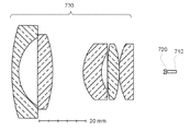
7A illustrates a cross-sectional view of an optical system for collimating a laser beam in a lidar system according to some embodiments of the invention.
7B illustrates a cross-sectional view of an optical system for collimating laser beams in a lidar system comprising two laser sources, according to some embodiments of the invention.
8 shows a simplified flow diagram illustrating a method of 3-dimensional imaging using a lidar system, in accordance with some embodiments of the present invention.
9 schematically illustrates a lidar system in accordance with some embodiments of the present invention.
10A illustrates a detector configuration according to some embodiments of the invention.
10B illustrates a detector that includes a single light sensor.
11A-11C schematically illustrate timing diagrams of laser pulses for the example illustrated in FIGS. 9 and 10, according to some embodiments of the invention.
12A shows a schematic top view of a detector according to some embodiments of the invention.
12B shows a schematic top view of a detector according to some embodiments of the invention.
13 schematically illustrates a lidar system in accordance with some embodiments of the present invention.
14 shows a simplified flow diagram illustrating a method of 3-dimensional imaging using a lidar system, in accordance with some embodiments of the present invention.
[0027] 본 발명은 일반적으로 3-차원 이미징을 위한 라이다 시스템들 및 방법들에 관한 것이다. 보다 구체적으로, 본 발명은 라이다 시스템들에서 개선된 분해능들을 위한 광학 및 검출기 설계들 및 방법들에 관한 것이다. 단지 예로서, 본 발명의 실시예들은, 비대칭 방출 영역 및 비대칭 발산 각도들을 갖는 레이저 소스에 의해 방출된 레이저 빔을 투사하기 위한 광학 시스템을 제공한다. 광학 시스템은, 레이저 소스의 앞에 배치된 음의 도수(예컨대, 평면-오목 원통형 렌즈(plano-concave cylindrical lens))를 갖는 원통형 렌즈를 포함할 수 있다. 원통형 렌즈는, 레이저 소스의 방출 영역을 실질적으로 대칭적이고 물리적 방출 영역보다 더 작은 가상 방출 영역으로 변환하도록 구성될 수 있다. 회전 대칭 투사 렌즈(예컨대, 구면 렌즈)와 결합하여, 원통형 렌즈 없이 달성될 것보다 더 작은 대칭적 원거리장 빔 스폿(또는 리턴 빔 스폿)이 달성될 수 있다. 라이다 시스템의 분해능이 원거리장 빔 스폿 크기에 의존할 수 있기 때문에, 이러한 광학 시스템은 라이다 시스템의 분해능을 개선할 수 있다. 본 발명의 실시예들은 또한 광 센서들의 어레이를 포함하는 검출기를 제공한다. 어레이 내의 각각의 광 센서는 리턴 레이저 빔 중 일부를 수신하고 검출하도록 구성될 수 있다. 이러한 검출기를 갖는 라이다 시스템은 단일 광 센서를 갖는 검출기와 비교하여 향상된 분해능들을 제공(afford)할 수 있다.[0027] The present invention relates generally to lidar systems and methods for three-dimensional imaging. More specifically, the present invention relates to optical and detector designs and methods for improved resolutions in lidar systems. By way of example only, embodiments of the present invention provide an optical system for projecting a laser beam emitted by a laser source having an asymmetric emission region and asymmetric divergence angles. The optical system may include a cylindrical lens having a negative frequency (eg, a plano-concave cylindrical lens) disposed in front of the laser source. The cylindrical lens can be configured to convert the emitting region of the laser source into a substantially symmetrical and smaller emitting region than the physical emitting region. In combination with a rotationally symmetrical projection lens (eg, spherical lens), a smaller symmetrical far field beam spot (or return beam spot) can be achieved than would be achieved without a cylindrical lens. Since the resolution of the lidar system can depend on the far field beam spot size, such an optical system can improve the resolution of the lidar system. Embodiments of the invention also provide a detector comprising an array of light sensors. Each optical sensor in the array can be configured to receive and detect a portion of the return laser beam. A lidar system with such a detector can provide improved resolution compared to a detector with a single light sensor.
[0028]
도 1은 본 발명의 일부 실시예들에 따라 3-차원 이미징을 위한 라이다 센서(100)를 개략적으로 예시한다. 라이다 센서(100)는 방출 렌즈(130) 및 수용 렌즈(140)를 포함한다. 라이다 센서(100)는 실질적으로 방출 렌즈(130)의 후방 초점 평면에 배치된 레이저 소스(110a)를 포함한다. 레이저 소스(110a)는 방출 렌즈(130)의 후방 초점 평면의 개개의 방출 위치로부터 레이저 펄스(120)를 방출하도록 동작한다. 방출 렌즈(130)는 라이다 센서(100)의 앞에 위치된 객체(150)를 향해 레이저 펄스(120)를 시준 및 지향시키도록 구성된다. 레이저 소스(110a)의 주어진 방출 위치에 대해, 시준된 레이저 펄스(120')는 객체(150)를 향해 대응하는 각도로 지향된다. [0028]
1 schematically illustrates a
[0029]
레이저 펄스(120)는 객체(150)로부터 반사될 수 있고, 이로써 수용 렌즈(140)를 향해 지향된 리턴 레이저 펄스(122)를 생성한다. 수용 렌즈(140)는 리턴 레이저 펄스(122)를 수용 렌즈(140)의 초점 평면의 대응하는 검출 위치에 포커싱하도록 구성된다. 라이다 센서(100)는 실질적으로 수용 렌즈(140)의 초점 평면에 배치된 검출기(160a)를 더 포함한다. 검출기(160a)는 대응하는 검출 위치에서 리턴 레이저 펄스(122)를 수신 및 검출하도록 구성된다. 검출기(160a)의 대응하는 검출 위치는 레이저 소스(110a)의 개개의 방출 위치와 결합(conjugate)된다. [0029]
The
[0030]
레이저 펄스(120)는 짧은 지속기간, 예컨대 100ns 펄스 폭일 수 있다. 라이다 센서(100)는 레이저 소스(110a) 및 검출기(160a)에 커플링된 프로세서(190)를 더 포함한다. 프로세서(190)는 리턴 레이저 펄스(122)의 TOF(time of flight)를 결정하도록 구성된다. 리턴 레이저 펄스(122)가 광속으로 이동하기 때문에, 라이다 센서(100)와 객체(150) 사이의 거리는 결정된 비행 시간에 기반하여 결정될 수 있다. [0030]
The
[0031]
일부 실시예들에 따라, 방출 렌즈(130) 및 수용 렌즈(140)가 고정될 수 있다. 레이저 소스(110a)는 방출 렌즈(130)의 후방 초점 평면의 복수의 방출 위치들로 래스터 스캐닝될 수 있고, 복수의 방출 위치들에서 복수의 레이저 펄스들을 방출하도록 구성된다. 개개의 방출 위치에서 방출된 각각의 레이저 펄스는 방출 렌즈(130)에 의해 시준되고 객체(150)를 향하여 개개의 각도로 지향되고, 객체(150)의 표면 상의 대응하는 지점에 입사한다. 따라서, 레이저 소스(110a)가 방출 렌즈(130)의 후방 초점 평면의 특정 영역 내에서 래스터 스캐닝될 때, 객체(150) 상의 대응하는 객체 영역이 스캐닝된다. 검출기(160a)는 수용 렌즈(140)의 초점 평면의 복수의 대응하는 검출 위치로 래스터 스캐닝된다. 검출기(160a)의 스캐닝은 레이저 소스(110a)의 스캐닝과 동기적으로 수행되어서, 검출기(160a) 및 레이저 소스(110a)는 임의의 주어진 시간에 항상 서로 결합된다. [0031]
According to some embodiments, the emitting
[0032]
개개의 방출 위치에서 방출된 각각의 레이저 펄스에 대한 비행 시간을 결정함으로써, 라이다 센서(100)로부터 객체(150)의 표면 상의 각각의 대응하는 지점까지의 거리가 결정될 수 있다. 일부 실시예들에서, 프로세서(190)는 각각의 방출 위치에서 레이저 소스(110a)의 위치를 검출하는 포지션 인코더에 커플링된다. 방출 위치에 기반하여, 시준된 레이저 펄스(120')의 각도가 결정될 수 있다. 객체(150)의 표면 상의 대응하는 지점의 X-Y 좌표는 라이다 센서(100)에 대한 각도 및 거리에 기반하여 결정될 수 있다. 따라서, 객체(150)의 3-차원 이미지는 라이다 센서(100)로부터 객체(150)의 표면 상의 다양한 지점들까지의 측정된 거리들에 기반하여 구성될 수 있다. 일부 실시예들에서, 3-차원 이미지는 지점 클라우드, 즉, 객체(150)의 표면 상의 지점들의 X, Y 및 Z 좌표들의 세트로서 표현될 수 있다. [0032]
By determining the flight time for each laser pulse emitted at an individual emission location, the distance from the
[0033]
대안적인 실시예들에서, 레이저 소스(110a) 및 검출기(160a)는 고정될 수 있다. 방출 렌즈(130)는 레이저 소스(110a)에 대해 스캐닝될 수 있고, 수용 렌즈(140)는 방출 렌즈(130)의 스캐닝과 동기적으로 검출기(160a)에 대하여 스캐닝될 수 있다. 일부 추가의 실시예들에서, 레이저 소스(110a) 및 검출기(160a)는 적어도 제1 방향으로 스캐닝될 수 있는 한편, 방출 렌즈(130) 및 수용 렌즈(140)는 적어도 제2 방향으로 스캐닝된다. 예컨대, 레이저 소스(110a) 및 검출기(160a)는 수평 방향으로 스캐닝될 수 있는 반면에, 방출 렌즈(130) 및 수용 렌즈(140)는 수직 방향으로 스캐닝될 수 있다. 일부 실시예들에서, 레이저 소스(110a) 및 검출기(160a)는 2개의 방향들로 스캐닝되는 반면에, 방출 렌즈(130) 및 수용 렌즈(140)는 또한 2개의 방향들로 스캐닝된다. 일부 실시예들에서, 레이저 소스(110a) 및 검출기(160a)는 리사주 패턴으로 2개의 방향들로 스캐닝될 수 있다. 방출 렌즈(130) 및 수용 렌즈(140)는 또한 리사주 패턴으로 2개의 방향들로 스캐닝될 수 있다.[0033]
In alternative embodiments,
[0034]
일부 실시예들에서, 레이저 소스(110a)는 FMCW(frequency-modulated continuous-wave) 레이저 빔을 방출하도록 구성될 수 있고, 프로세서(190)는 리턴 레이저 빔을 복조함으로써 객체(150)와 라이다 센서(100) 사이의 거리를 결정하도록 구성될 수 있다. [0034]
In some embodiments, the
[0035]
일부 실시예들에서, 방출 렌즈(130) 및 수용 렌즈(140)는 동일한 렌즈를 포함할 수 있고; 즉, 단일 렌즈는 레이저 소스(110a)에 의해 방출된 레이저 펄스(120)를 시준하여 객체(150)를 향해 지향시킬 뿐만 아니라, 리턴 레이저 펄스(122)를 검출기(160a)에 포커싱하도록 구성될 수 있다. [0035]
In some embodiments, the emitting
[0036] 일부 실시예들에서, 검출기의 포화를 방지하거나, 눈-안전성을 개선하거나, 전체 전력 소비를 감소시키기 위해, 리턴 레이저 펄스의 강도가 측정되고 동일한 방출 지점으로부터 후속 레이저 펄스들의 파워를 조정하는 데 사용된다. 레이저 펄스의 파워는 레이저 펄스의 지속기간, 레이저에 인가된 전압 또는 전류, 또는 레이저에 전력을 공급하는 데 사용되는 커패시터에 저장된 전하를 변동시킴으로써 변동될 수 있다. 후자의 경우, 커패시터에 저장된 전하는 커패시터에 대한 충전 시간, 충전 전압 또는 충전 전류를 변동시킴으로써 변동될 수 있다. 일부 실시예들에서, 강도는 또한 이미지에 다른 차원을 추가하기 위해 사용될 수 있다. 예컨대, 이미지는 반사도(또는 밝기)뿐만 아니라 X, Y 및 Z 좌표들을 포함할 수 있다. [0036] In some embodiments, the intensity of the return laser pulse is measured and used to adjust the power of subsequent laser pulses from the same emission point to prevent saturation of the detector, improve eye-safety, or reduce overall power consumption do. The power of the laser pulse can be varied by varying the duration of the laser pulse, the voltage or current applied to the laser, or the charge stored in the capacitor used to power the laser. In the latter case, the charge stored in the capacitor can be varied by varying the charging time, charging voltage or charging current for the capacitor. In some embodiments, intensity can also be used to add another dimension to the image. For example, the image may include X, Y and Z coordinates as well as reflectivity (or brightness).
[0037]
라이다 센서(100)의 AFOV(angular field of view)는 레이저 소스(110a)의 스캐닝 범위 및 방출 렌즈(130)의 초점 길이에 기반하여 다음과 같이 추정될 수 있고:[0037]
The angular field of view (AFOV) of the
![]()
![]()
여기서 h는 특정 방향을 따른 레이저 소스(110a)의 스캔 범위이고, f는 방출 렌즈(130)의 초점 길이이다. 주어진 스캔 범위(h)에 대해, 더 짧은 초점 길이들은 더 넓은 AFOV들을 생성할 것이다. 주어진 초점 길이(f)에 대해, 더 큰 스캔 범위들은 더 넓은 AFOV들을 생성할 것이다. Where h is the scan range of the
[0038]
일부 실시예들에서, 라이다 센서(100)는 방출 렌즈(130)의 후방 초점 평면에 어레이로서 배치된 다수의 레이저 소스들을 포함할 수 있어서, 각각의 개별 레이저 소스의 스캔 범위를 비교적 작게 유지하면서 더 큰 총 AFOV가 달성될 수 있다. 따라서, 라이다 센서(100)는 수용 렌즈(140)의 초점 평면에 어레이로서 배치된 다수의 검출기들을 포함할 수 있으며, 각각의 검출기는 개개의 레이저 소스와 결합된다. 예컨대, 라이다 센서(100)는 도 1에 예시된 바와 같이 제2 레이저 소스(110b) 및 제2 검출기(160b)를 포함할 수 있다. 다른 실시예들에서, 라이다 센서(100)는 4개의 레이저 소스들 및 4개의 검출기들, 또는 8개의 레이저 소스들 및 8개의 검출기들을 포함할 수 있다. 일 실시예에서, 라이다 센서(100)는 4×2 어레이로서 배열된 8개의 레이저 소스들 및 4×2 어레이로서 배열된 8개의 검출기들을 포함할 수 있어서, 라이다 센서(100)는 수직 방향에서 그의 AFOV보다 수평 방향에서 더 넓은 AFOV를 가질 수 있다. 다양한 실시예들에 따라, 라이다 센서(100)의 총 AFOV는 방출 렌즈의 초점 길이, 각각의 레이저 소스의 스캔 범위 및 레이저 소스들의 수에 의존하여 약 5도 내지 약 15도, 또는 약 15도 내지 약 45도, 또는 약 45도 내지 약 90 도의 범위에 있을 수 있다. [0038]
In some embodiments, the
[0039]
레이저 소스(110a)는 자외선, 가시 또는 근적외선 파장 범위들의 레이저 펄스들을 방출하도록 구성될 수 있다. 각각의 레이저 펄스의 에너지는 대략 마이크로줄(microjoule) 정도일 수 있으며, 이는 일반적으로 KHz 범위의 반복 레이트들에 대해 눈에 안전한 것으로 간주된다. 약 1500nm보다 큰 파장들에서 동작하는 레이저 소스들에 대해, 에너지 레벨들은, 눈이 그러한 파장에 포커싱하지 않기 때문에 더 높아질 수 있다. 검출기(160a)는 실리콘 애벌랜치 광 센서(silicon avalanche photo sensor), 광전자 증배기, PIN 다이오드, 또는 다른 반도체 센서들을 포함할 수 있다.[0039]
The
[0040]
일부 레이저 소스들, 예컨대, 고체 상태 레이저들은 근거리장뿐만 아니라 원거리장에서도 비대칭 방출 영역 및 비대칭 빔 프로파일을 가질 수 있다. 도 2는 세장형 방출 영역(220)을 갖는 레이저 소스(210), 예컨대, 반도체 레이저 소스를 개략적으로 예시한다. 방출 영역(220)은 수직 방향의 높이(h), 및 높이(h)보다 더 큰 수평 방향의 폭(w)을 가질 수 있다. 예컨대, 라이다 시스템에 사용되는 고체 상태 레이저에 대해, 높이(h)는 약 10㎛일 수 있고, 폭(w)은 약 200㎛일 수 있다. 방출 영역(220)이 도 2에서 직사각형 형상을 갖는 것으로 예시되지만, 방출 영역(220)은 둥근 코너들을 갖는 직사각형 형상 또는 타원 형상을 가질 수 있다.[0040]
Some laser sources, such as solid state lasers, can have an asymmetric emission region and an asymmetric beam profile not only in the near field but also in the far field. 2 schematically illustrates a
[0041]
이러한 레이저 소스들에 의해 방출된 레이저 빔은 또한 수평 및 수직 방향들에서 상이한 발산 각도들을 가질 수 있다. 도 2에 예시된 바와 같이, (예컨대, 접선 평면(tangential plane)에서) 수평 방출 팬(240)은 각도(φ1)(이는 본원에서 각도 발산으로 지칭될 수 있음)를 마주 대하고(subtend), (예컨대, 시상면(sagittal plane)에서) 수직 방출 팬(230)은 φ1보다 큰 각도(φ2)를 마주 대할 수 있다. 예컨대, 수평 방출 팬(240)의 각도 발산(φ1)은 약 10도이고, 수직 방출 팬(230)의 각도 발산(φ2)은 약 25 도일 수 있다. 다시 말해서, 광 빔은 수평 방향에서 더 큰 소스 치수 및 더 작은 발산을 가지며, 수직 방향에서 더 작은 소스 치수 및 더 큰 발산을 갖는다. 레이저 빔이 수직 방향으로 더 빨리 발산하기 때문에, 수직 방향은 고속 축으로 지칭될 수 있고, 수평 방향은 저속 축으로 지칭될 수 있다. The laser beam emitted by these laser sources may also have different divergence angles in horizontal and vertical directions. As illustrated in FIG. 2, the horizontal discharge fan 240 (eg, in a tangential plane) faces the angle φ 1 (which may be referred to herein as angular divergence). , The vertical discharge fan 230 (eg, in a sagittal plane) may face an angle φ 2 greater than φ 1 . For example, the angle divergence φ 1 of the
[0042]
위에 설명된 바와 같은 레이저 빔의 비대칭 방출 영역 및 비대칭 각도 발산은, 구면 렌즈들 또는 비구면 렌즈들과 같은 회전 대칭 렌즈들을 사용하여 수평 및 수직 방향들 둘 모두로 레이저 빔을 시준하는 것을 더 어렵게 만들 수 있다. 도 3a 및 3b는 라이다 시스템에서 레이저 빔을 시준하기 위한 광학 시스템을 개략적으로 예시한다. 광학 시스템은 레이저 소스(210)의 앞에 위치된 구면 렌즈(310)를 포함한다(구면 렌즈(310)는, 예컨대, 도 1에 예시된 방출 렌즈(130)일 수 있다). 도 3a는 수평 방출 팬에 대한 광 경로들을 예시하고, 도 3b는 수직 방출 팬에 대한 광 경로들을 예시한다. [0042]
The asymmetric emission area and asymmetric angle divergence of the laser beam as described above can make it more difficult to collimate the laser beam in both horizontal and vertical directions using rotationally symmetric lenses such as spherical lenses or aspherical lenses. have. 3A and 3B schematically illustrate an optical system for collimating a laser beam in a lidar system. The optical system includes a
[0043]
도 3b에 예시된 바와 같이, 레이저 소스(210)의 방출 표면이 렌즈(310)의 대략 후방 초점 평면에 위치되면, 수직 방출 팬의 광선들은 렌즈(310)에 의해 실질적으로 시준될 수 있고; 즉, 광학 경로를 따라 렌즈(310) 뒤의 광선들은 서로 거의 평행할 수 있다. 반면에, 도 3a에 예시된 바와 같이, 렌즈(310)의 도수가 수평 방출 팬을 시준하기에는 너무 클 수 있기 때문에, 수평 방출 팬의 광선들은 광학 경로를 따라 렌즈(310) 뒤에 수렴될 수 있고, 수평 방출 팬은 수직 방출 팬의 발산 각도(φ2)보다 더 작은 발산 각도(φ1)를 갖는다. 다시 말해서, 수평 방출 팬을 시준하기 위해, 렌즈(310)의 도수보다 더 작은 도수(따라서 더 긴 초점 길이)를 갖는 렌즈가 요구될 수 있다. As illustrated in FIG. 3B, when the emitting surface of the
[0044]
위에 설명된 바와 같은 레이저 소스의 비대칭 방출 영역 및 비대칭 발산 각도들로 인해, 라이다 시스템에서 검출기 상에 이미징된 리턴 빔 스폿은 또한 비대칭적일 수 있다. 예컨대, 도 1에 예시된 라이다 시스템(100)에서, 구면 방출 렌즈(130)에 의해, 객체(150)에서의 원거리장 빔 스폿은 비대칭적일 수 있고; 결과적으로, 구면 수용 렌즈(140)에 의해 검출기(160a) 상에 이미징된 리턴 빔 스폿은 또한 비대칭적일 수 있다. 라이다 시스템의 각도 분해능이 리턴 빔 스폿 크기에 의존할 수 있기 때문에, 비대칭 리턴 빔 스폿은 라이다 시스템의 분해능을 제한할 수 있다.[0044]
Due to the asymmetric emission region and the asymmetric divergence angles of the laser source as described above, the return beam spot imaged on the detector in the lidar system can also be asymmetric. For example, in the
I. 개선된 분해능을 위한 광학 설계들I. Optical designs for improved resolution
[0045]
본 발명의 일부 실시예들에 따라, 음의 도수를 갖는 원통형 렌즈는, 수평 및 수직 방향들에서 비교적 균일한 각도 분해능을 달성하기 위해, 회전 대칭 방출 렌즈와 결합하여, 사용될 수 있다. 도 4a-4b는 일부 실시예들에 따른 라이다 시스템에서 레이저 빔을 투사하기 위한 광학 시스템을 개략적으로 예시한다. 광학 시스템은 레이저 소스(210)의 앞에 위치된 평면-오목 원통형 렌즈(410)를 포함한다. 원통형 렌즈(410)의 도수 축은 실질적으로 수평 방향을 따를 수 있다. 즉, 원통형 렌즈(410)는, 도 4a에 예시된 바와 같이, 수평 방향으로 0이 아닌 도수를 가질 수 있고, 도 4b에 예시된 바와 같이, 수직 방향으로 거의 도수가 없다. [0045]
According to some embodiments of the present invention, a cylindrical lens with a negative power may be used in combination with a rotationally symmetrical emitting lens, to achieve relatively uniform angular resolution in horizontal and vertical directions. 4A-4B schematically illustrate an optical system for projecting a laser beam in a lidar system according to some embodiments. The optical system includes a planar-concave
[0046]
도 4a에 예시된 바와 같이, 원통형 렌즈(410)는 수평 방출 팬의 각도 발산을 φ1로부터 φ1'로 확장시키도록 구성될 수 있다. 확장된 수평 방출 팬은, 실제 폭(w) 미만인 가상 폭(w')을 갖는 가상 방출 영역으로부터 방출되는 것처럼 보일 수 있다. 일부 실시예들에서, 원통형 렌즈(410)는, 가상 폭(w')이 수직 방출 팬의 높이(h)와 실질적으로 동일하도록 구성될 수 있다. [0046] As illustrated in Figure 4a, the
[0047]
도 4b에 예시된 바와 같이, 원통형 렌즈(410)가 수직 방향에서 어떠한 광학 도수도 갖지 않기 때문에, 수직 방출 팬의 각도 발산(φ2)은 원통형 렌즈(410)에 의해 영향을 받지 않는다. 일부 실시예들에서, 수평 방출 팬의 확장된 각도 발산(φ1')은 수직 방출 팬의 각도 발산(φ2)과 실질적으로 동일할 수 있다. 따라서, 수평 방출 팬 및 수직 방출 팬 둘 모두는, 도 4a-4b에 예시된 바와 같이, 렌즈(310)에 의해 시준될 수 있다. As illustrated in FIG. 4B, since the
[0048]
비록 도 4a-4b가 원통형 렌즈(410)가 평면-오목 형상을 갖는 예시적인 실시예를 도시하지만, 일부 실시예들에 따라, 다른 타입들의 원통형 렌즈(예컨대, 이중 오목 원통형 렌즈 또는 메니스커스(meniscus) 원통형 렌즈)가 사용될 수 있다. [0048]
Although FIGS. 4A-4B show an exemplary embodiment in which the
[0049]
도 5a-5d는, 원통형 렌즈(410)가 원거리장 빔 스폿 형상에 가질 수 있는 효과를 개략적으로 예시한다. 도 5a 및 5c에 예시된 바와 같이, 원통형 렌즈(410) 없이, 원거리장 빔 스폿(510)은 비대칭 방출 영역 및 비대칭 발산 각도들로 인해 수평 방향으로 연장될 수 있다. 도 5b에 예시된 바와 같이, 레이저 소스(210)와 방출 렌즈(310) 사이에 원통형 렌즈(410)를 삽입함으로써, 수평 방출 팬의 광선들뿐만 아니라 수직 방출 팬(도시되지 않음)의 광선들이 시준될 수 있다. 결과적으로, 원거리장 빔 스폿(520)은, 도 5d에 예시된 바와 같이, 수평 및 수직 방향들로 실질적으로 대칭적일 수 있다.[0049]
5A-5D schematically illustrate the effect that the
[0050] 통상적으로, 양의 도수를 갖는 원통형 렌즈(예컨대, 평면-볼록 원통형 렌즈)는, 레이저 빔을 원형화(circularize)하기 위해 레이저와 구면 시준 렌즈 사이에 배치된다. 예컨대, 양의 도수를 갖는 원통형 렌즈는, 수직 방출 팬의 발산 각도를 감소시키기 위해 도수 축이 수직 방향으로 정렬되도록 배향될 수 있다. 결과적으로, 레이저 빔을 시준하기 위해, 도 4a 및 4b에 예시된 구성과 비교하여, 초점 길이가 증가된 시준 렌즈가 요구될 수 있다. 시준 렌즈의 더 긴 초점 길이는 라이다 시스템의 더 큰 물리적 크기로 이어질 수 있고, 따라서 라이다 시스템의 제조 비용이 증가시킬 수 있다.[0050] Typically, a cylindrical lens with a positive frequency (eg, a plano-convex cylindrical lens) is placed between the laser and a spherical collimating lens to circularize the laser beam. For example, a cylindrical lens having a positive frequency can be oriented such that the frequency axis is aligned in the vertical direction to reduce the divergence angle of the vertical emission fan. Consequently, in order to collimate the laser beam, a collimating lens with increased focal length may be required, compared to the configuration illustrated in FIGS. 4A and 4B. The longer focal length of the collimating lens can lead to a larger physical size of the lidar system, thus increasing the manufacturing cost of the lidar system.
[0051]
음의 도수를 갖는 원통형 렌즈를 사용하는 것이 스캐닝 라이다 시스템에서 특히 유리할 수 있다. 예컨대, 도 1에 예시된 스캐닝 라이다 시스템에서, 방출 렌즈(130) 및 수용 렌즈(140)는 고정되는 반면에, 레이저 소스들(110a 및 110b) 및 검출기들(160a 및 160b)은 방출 렌즈(130) 및 수용 렌즈(140)의 초점 평면들에서 각각 스캐닝된다. 스캐닝 거리는 주어진 각도 FOV(field of view)를 달성하기 위해 방출 렌즈(130)의 초점 길이에 비례할 수 있다. 따라서, 초점 길이가 더 짧은 방출 렌즈(130)를 사용함으로써, 동일한 FOV를 유지하면서 스캐닝 거리가 단축될 수 있다.[0051]
The use of a cylindrical lens with a negative frequency can be particularly advantageous in a scanning lidar system. For example, in the scanning lidar system illustrated in FIG. 1, the
[0052]
도 6a는, 라이다 시스템에 사용될 수 있는 레이저 소스(610) 및 원통형 렌즈(640)의 예시적인 구성을 개략적으로 예시한다. 레이저 소스(610)는 투명 커버(630)에 의해 캡슐화된 레이저 다이(620)를 포함할 수 있다. 일부 실시예들에 따라, 원통형 렌즈(640)의 초점 길이는 약 -0.2 mm 내지 약 -5 mm의 범위일 수 있다. 평면-오목 형상을 갖는 원통형 렌즈(640)에 대해, 도 6a에 예시된 바와 같이, 오목한 표면의 곡률의 반경은 약 -0.1 mm 내지 약 -2 mm의 범위(예컨대, 약 -0.5 mm)일 수 있다. 원통형 렌즈(640)는, 레이저 다이(620)의 방출 표면으로부터 약 0.2mm 내지 약 5mm 범위(예컨대, 약 1mm)의 거리(d)에 배치될 수 있다. 원통형 렌즈의 특정 바람직하지 않은 광학 효과들(예컨대, 수평 및 수직 방향들에서 약간 상이한 최상의 초점 평면들, 이는 난시(astigmatism)로 지칭될 수 있음)을 최소화하기 위해, 원통형 렌즈(640)를 레이저 다이(620)의 방출 표면에 매우 근접하게 배치하는 것이 유리할 수 있다. 원통형 렌즈(640)와 레이저 다이(620)의 방출 표면 사이의 거리(d)는 원통형 렌즈(640)의 초점 길이와 유사하지만 동일하지 않을 수 있으며, 원통형 렌즈(640)의 두께 및 원통형 렌즈(640)의 형상(예컨대, 원통형 렌즈(640)가 평면 오목형인지 또는 이중 오목형인지)에 의존할 수 있다.[0052]
6A schematically illustrates an exemplary configuration of a
[0053]
도 6b는 일부 실시예들에 따른, 레이저 소스(650) 및 원통형 렌즈(670)의 다른 예시적인 구성을 개략적으로 예시한다. 여기서, 원통형 렌즈(670)는 레이저 다이(660)를 캡슐화하는 커버 내에서 직접 몰딩된다. 일부 실시예들에서, 원통형 렌즈(670)의 초점 길이는 약 -0.1 mm 내지 약 -2 mm의 범위일 수 있다. 오목한 표면의 정점(apex)과 레이저 다이(660)의 방출 표면 사이의 거리(d')는 약 0.1 mm 내지 약 2 mm의 범위일 수 있다. 거리(d')는 원통형 렌즈(670)의 초점 길이와 유사하지만 동일하지 않을 수 있다.[0053]
6B schematically illustrates another example configuration of a
[0054]
도 7a는 일부 실시예들에 따른 라이다 시스템에서 레이저 빔을 투사하기 위한 광학 시스템의 단면도를 예시한다. 원통형 렌즈(720)는 레이저 소스(710)(예컨대, 레이저 다이오드)의 앞에 배치된다. 구면 방출 렌즈(730)는 원통형 렌즈(720)의 앞에 위치된다. 방출 렌즈(730)는 몇몇의 렌즈 컴포넌트들을 포함하는 복합 렌즈일 수 있다. 일부 실시예들에서, 방출 렌즈(730)는 약 5 mm 내지 약 50 mm의 범위(예컨대, 약 16 mm)의 초점 길이를 가질 수 있다. 방출 렌즈(730)의 직경(예컨대, 개구)은 약 5 mm 내지 약 100 mm의 범위(예컨대, 40 mm)일 수 있다. [0054]
7A illustrates a cross-sectional view of an optical system for projecting a laser beam in a lidar system according to some embodiments. The
[0055]
일부 실시예들에서, 라이다 시스템은, 어레이로 배열된 단일 구면 방출 렌즈에 의해 투사되는 다수의 레이저 소스들을 포함할 수 있다. 이러한 경우들에서, 각각의 레이저 소스는 그 자신의 원통형 렌즈와 페어링될 수 있다. 도 7b는, 라이다 시스템이 2개의 레이저 소스들(710a 및 710b)을 포함하는 예시적인 실시예를 예시한다. 제1 원통형 렌즈(720a)는 제1 레이저 소스(710a)와 페어링되고, 제2 원통형 렌즈(720b)는 제2 레이저 소스(710b)와 페어링된다. 2개의 레이저 소스들(710a 및 710b)은 동일한 구면 방출 렌즈(730)를 공유한다.[0055]
In some embodiments, the lidar system may include multiple laser sources projected by a single spherical emission lens arranged in an array. In these cases, each laser source can be paired with its own cylindrical lens. 7B illustrates an exemplary embodiment in which the lidar system includes two
[0056]
도 8은 본 발명의 일부 실시예들에 따라, 라이다 시스템을 이용한 3-차원 이미징의 방법(800)을 예시하는 간략화된 흐름도를 도시한다.[0056]
8 shows a simplified flow diagram illustrating a
[0057]
방법(800)은, 802에서, 레이저 소스 및 원통형 렌즈를 일제히 병진운동시키는 단계를 포함할 수 있다. 레이저 소스는 방출 평면의 복수의 방출 위치들 각각으로 병진운동된다. 레이저 소스는 제1 높이 및 제1 높이보다 더 큰 제1 폭을 갖는 방출 영역을 갖는다. 원통형 렌즈는 음의 도수를 갖고 레이저 소스의 앞에 위치된다. 원통형 렌즈는, 원통형 렌즈의 도수 축이 실질적으로 폭 방향이 되도록 배향된다. 원통형 렌즈는 레이저 소스의 방출 영역을 가상 폭 및 가상 높이를 갖는 가상 방출 영역으로 변환하도록 구성될 수 있고, 여기서 가상 폭은 방출 영역의 제1 폭 미만이다. 원통형 렌즈는 평면-오목 원통형 렌즈 또는 이중-오목 원통형 렌즈일 수 있다. 일부 실시예들에서, 원통형 렌즈는 레이저 소스와 단일 패키지로 통합될 수 있다.[0057]
[0058]
방법(800)은, 804에서, 레이저 소스를 사용하여, 복수의 레이저 펄스들을 방출하는 단계를 더 포함할 수 있다. 복수의 레이저 펄스들 각각은 복수의 방출 위치들 중 개개의 방출 위치에서 방출된다. 방법(800)은, 806에서, 방출 렌즈를 사용하여, 복수의 레이저 펄스들을 하나 이상의 객체들을 향해 시준 및 지향시키는 단계를 더 포함할 수 있다. 하나 이상의 객체들은 복수의 리턴 레이저 펄스들을 생성하기 위해 복수의 레이저 펄스들 각각을 반사시킬 수 있다.[0058]
[0059]
방법(800)은, 808에서, 수용 렌즈를 사용하여, 복수의 리턴 레이저 펄스들 각각을 수신하여, 검출 평면의 복수의 대응하는 검출 위치들에 포커싱하는 단계를 더 포함할 수 있다. 각각의 대응하는 검출 위치는 개개의 방출 위치와 결합(conjugate)한다. 일부 실시예들에서, 수용 렌즈 및 송신 렌즈는 동일한 렌즈, 즉, 복수의 레이저 펄스들을 하나 이상의 객체들을 향해 시준 및 지향시킬 뿐만 아니라, 복수의 리턴 레이저 펄스들을 포커싱하도록 구성된 동일한 렌즈일 수 있다.[0059]
The
[0060]
방법(800)은, 810에서, 검출기를 검출 평면의 복수의 대응하는 검출 위치들 각각으로 병진운동시키는 단계; 및 812에서, 검출기를 사용하여, 복수의 검출 위치들의 각각의 개개의 검출 위치에서 복수의 리턴 레이저 펄스들의 각각의 개개의 리턴 레이저 펄스를 검출하는 단계를 더 포함할 수 있다.[0060]
[0061]
방법(800)은, 814에서, 프로세서를 사용하여, 복수의 리턴 레이저 펄스들 각각에 대한 비행 시간을 결정하는 단계, 및 816에서, 프로세서를 사용하여, 복수의 리턴 레이저 펄스들 각각에 대한 비행 시간에 기반하여 하나 이상의 객체들의 3-차원 이미지를 구성하는 단계를 더 포함할 수 있다.[0061]
[0062] 일부 실시예들에서, 레이저 소스 및 검출기 각각은 하나의 차원에서 또는 2개의 차원들에서 병진운동된다. 일부 실시예들에서, 레이저 소스 및 검출기는 리사주 패턴(Lissajous pattern)으로 2개의 방향들로 스캐닝될 수 있다. 일부 실시예들에서, 방출 렌즈 및 수용 렌즈는 고정되는 반면에, 레이저 소스 및 검출기는 병진운동된다. [0062] In some embodiments, each of the laser source and detector is translated in one dimension or in two dimensions. In some embodiments, the laser source and detector can be scanned in two directions in a Lissajous pattern. In some embodiments, the emitting lens and receiving lens are fixed, while the laser source and detector are translated.
[0063]
일부 다른 실시예들에서, 방법(800)은 방출 렌즈의 광학 축에 실질적으로 직교하는 평면에서 레이저 소스에 대해 방출 렌즈를 병진운동시키는 단계; 및 방출 렌즈의 병진운동과 동기적으로 평면에서 검출기에 대해 수용 렌즈를 병진운동시키는 단계를 더 포함할 수 있다. 일부 실시예들에서, 방출 렌즈 및 수용 렌즈 각각은 하나의 차원에서 또는 2개의 차원들에서 병진운동된다. 일부 실시예들에서, 방출 렌즈 및 수신 렌즈는 리사주 패턴으로 2개의 방향들로 스캐닝될 수 있다.[0063]
In some other embodiments,
[0064] 도 8에 예시된 특정 단계들은 본 발명의 일부 실시예들에 따라, 라이다 시스템을 사용하여 3차원 이미징을 수행하는 특정한 방법을 제공한다는 것이 인식되어야 한다. 또한, 단계들의 다른 시퀀스들이 대안적 실시예들에 따라 수행될 수 있다. 예컨대, 본 발명의 대안적인 실시예들은, 위에서 약술된 단계들을 상이한 순서로 수행할 수 있다. 더욱이, 도 8에 예시된 개별 단계들은, 개별 단계에 적절한 바와 같은 다양한 시퀀스들로 수행될 수 있는 다수의 서브-단계들을 포함할 수 있다. 또한, 특정한 애플리케이션들에 의존하여 부가적인 단계들이 부가될 수 있고 일부 단계들이 제거될 수 있다. 당업자는, 다수의 변동들, 수정들, 및 대안들을 인식할 것이다.[0064] It should be appreciated that the specific steps illustrated in FIG. 8 provide a specific method of performing three-dimensional imaging using a lidar system, in accordance with some embodiments of the present invention. Also, other sequences of steps may be performed according to alternative embodiments. For example, alternative embodiments of the present invention may perform the steps outlined above in a different order. Moreover, the individual steps illustrated in FIG. 8 can include multiple sub-steps that can be performed in various sequences as appropriate for the individual step. Also, depending on the specific applications, additional steps may be added and some steps may be removed. Those skilled in the art will recognize a number of variations, modifications, and alternatives.
II. 개선된 분해능을 위한 검출기 설계들II. Detector designs for improved resolution
[0065]
일부 실시예들에 따라, 라이다 시스템의 분해능을 개선하기 위한 다른 접근법이 검출기 측에서 구현될 수 있다. 도 5a 및 5c에 예시된 바와 같이, 원통형 렌즈를 사용하지 않고서, 원거리장 빔 스폿(510)은 수평 방향으로 연장될 수 있다. 결과적으로, 검출기(예컨대, 도 1에 예시된 검출기(160a 또는 160b)) 상의 수용 렌즈(예컨대, 도 1에 예시된 수용 렌즈(140))에 의해 형성된 원거리장 빔 스폿(510)의 이미지는 또한 수평 방향으로 연장될 수 있다. [0065]
According to some embodiments, another approach to improving the resolution of the lidar system can be implemented at the detector side. 5A and 5C, the far-
[0066]
도 9는 일부 실시예들에 따른 라이다 시스템(900)을 개략적으로 예시한다. 도 1에 예시된 라이다 시스템(100)과 유사하게, 라이다 시스템(900)은 레이저 소스(910) 및 레이저 소스(910)에 의해 방출된 레이저 빔을 시준하기 위한 방출 렌즈(930)를 포함할 수 있다. 시준된 레이저 빔은 하나 이상의 객체들(950a 및 950b)로부터 반사될 수 있다. 라이다 시스템(900)은 리턴 레이저 빔을 포커싱하기 위한 수용 렌즈(940), 및 포커싱된 리턴 레이저 빔을 검출하기 위해 수용 렌즈(940)의 초점 평면에 위치된 검출기(920)를 더 포함할 수 있다. 위에서 논의된 바와 같이, 방출된 레이저 빔의 비대칭 프로파일로 인해, 검출기(920)에서 리턴 레이저 빔의 포커싱된 스폿이 연장될 수 있다. 도 10은, 수평 방향으로 연장된 수용 렌즈(940)의 초점 평면에서 이미징된 리턴 빔 스폿(1010)을 개략적으로 예시한다.[0066]
9 schematically illustrates a
[0067]
일부 실시예들에 따라, 검출기(920)는 광 센서들의 어레이를 포함할 수 있다. 예컨대, 검출기(920)는, 수평 방향으로 1-차원 어레이로서 나란히 배열된 2개의 광 센서들(922a 및 922b)을 포함할 수 있다. 도 9 및 10에 예시된 바와 같이, 각각의 광 센서(922a 또는 922b)는 리턴 빔 스폿(1010)의 일부를 커버하는 감지 영역을 갖는다. 따라서, 제1 광 센서(922a)는 리턴 레이저 빔의 좌측 절반을 검출할 수 있고, 제2 광 센서(922b)는 리턴 레이저 빔의 우측 절반을 검출할 수 있다. [0067]
According to some embodiments,
[0068]
예시적인 예로서, 도 9는, 레이저 빔이 원거리장에서 레이저 빔의 FOV(960) 내에 위치된 2개의 객체들(950a 및 950b)(예컨대, 2명의 사람들) 상에 투사될 수 있음을 도시한다. 원거리장에서의 레이저 스폿 크기는, 레이저 소스의 방출 영역의 치수와 레이저 소스로부터 객체까지의 거리를 곱하고 방출 렌즈(930)의 초점 길이로 나눠진 크기와 대략 동일할 수 있다. 제1 객체(950a)로부터 반사된 리턴 레이저 빔의 제1 부분(실선들로 예시된 광선들로 표현됨)은 리턴 빔 스폿(1010)의 좌측 절반에 이미징될 수 있고; 제2 객체(950b)로부터 반사된 리턴 레이저 빔의 제2 부분(점선들로 예시된 광선들로 표현됨)은 리턴 빔 스폿(1010)의 우측 절반에 이미징될 수 있다. 도 9 및 10a에 예시된 바와 같이, 제1 광 센서(922a)는 제1 객체(950a)로부터 반사된 리턴 레이저 빔의 제1 부분을 검출할 수 있고, 제2 광 센서(922b)는 제2 객체(950b)로부터 반사된 리턴 레이저 빔의 제2 부분을 검출할 수 있다. 따라서, 라이다 시스템(900)은 2개의 객체들(950a 및 950b)을 분석할 수 있다. "수직" 및 "수평" 배향들이 도면들 및 설명의 맥락에서 스위칭될 수 있거나, 배향이 당업자에게 명백한 바와 같이 임의로 회전될 수 있음이 이해되어야 한다.[0068]
As an illustrative example, FIG. 9 shows that a laser beam can be projected onto two
[0069]
비교를 위해, 도 10b는, 전체 리턴 빔 스폿(1010)을 포함하는 감지 영역을 갖는 단일 광 센서(1030)를 포함하는 검출기(1020)를 예시한다. 이 구성에서, 단일 리턴 레이저 펄스가 검출기(1020)에 의해 검출될 수 있기 때문에, 라이다 시스템(900)은 2개의 객체들(950a 및 950b)을 분석할 수 없을 수 있다. 따라서, 도 9 및 10a에 예시된 바와 같이 수평 방향으로 어레이로서 배열된 2개의 광 센서들(922a 및 922b)을 가짐으로써, 수평 방향의 라이다 시스템(900)의 분해능은 단일 광 센서(1030)를 갖는 검출기(1020)과 비교하여 대략 2 배가 될 수 있다.[0069]
For comparison, FIG. 10B illustrates a
[0070]
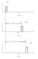
일부 실시예들에 따라, 검출기(920)는 개별 광 센서들에 대한 별개의 출력들을 가질 수 있어서, 각각의 광 센서에 의해 검출된 리턴 레이저 펄스의 각각의 부분에 대한 비행 시간이 독립적으로 결정될 수 있다. 도 11a-11c는 도 9 및 10에 예시된 예에 대한 레이저 펄스들의 타이밍도들을 개략적으로 예시한다. 도 11a에 예시된 바와 같이, 레이저 펄스(1110)는 제1 시간 인스턴스(t1)에서 레이저 소스(910)에 의해 방출될 수 있다. 레이저 펄스(1110)는 제1 객체(950a) 및 제2 객체(950b)로부터 반사될 수 있다. 도 11b에 예시된 바와 같이, 제1 객체(950a)로부터 반사된 리턴 레이저 펄스의 제1 부분은 제2 시간 인스턴스(t2)에서 제1 광 센서(922a)에 의해 검출될 수 있다. t1과 t2 사이의 경과된 시간은 Δt1로 결정될 수 있다. 라이다 시스템(900)과 제1 객체(950a) 사이의 거리(L1)는 Δt1에 기반하여 결정될 수 있다. 유사하게, 도 11c에 예시된 바와 같이, 제2 객체(950b)로부터 반사된 리턴 레이저 펄스의 제2 부분은 제3 시간 인스턴스(t3)에서 제2 광 센서(922b)에 의해 검출될 수 있다. t1과 t3 사이의 경과된 시간은 Δt2로 결정될 수 있다. 라이다 시스템(900)과 제2 객체(950b) 사이의 거리(L2)는 Δt2에 기반하여 결정될 수 있다. 따라서, 별개의 출력들을 갖는 검출기(920)에서 2개의 광 센서들(922a 및 922b)을 가짐으로써, 라이다 시스템(900)은 2개의 객체들(950a 및 950b)의 상이한 거리들(L1 및 L2)을 분석할 수 있다. According to some embodiments, the
[0071]
도 12a는 일부 실시예들에 따른 검출기(1210)의 개략적인 평면도를 도시한다. 검출기(1210)는 광 센서들(1212a 및 1212b)을 포함하는 1×2 어레이와 같은 광 센서들의 1 차원 어레이를 포함할 수 있다. 광 센서들의 1×2 어레이가 도 12a에 예시되지만, 검출기(1210)는 광 센서들의 1×3 어레이, 광 센서들의 1×4 어레이 등을 포함할 수 있다. 예컨대, 1×3 어레이를 사용함으로써, 어레이 방향의 분해능의 대략 3 배의 개선이 달성될 수 있다.[0071]
12A shows a schematic top view of a
[0072]
도 12b는 일부 실시예들에 따른 검출기(1220)의 개략적인 평면도를 도시한다. 검출기(1220)는 광 센서들(1222a-1222f)을 포함하는 2×3 어레이와 같은 2-차원 어레이를 포함할 수 있다. 따라서, 일 방향의 분해능의 대략 2 배의 개선, 및 직교 방향의 분해능의 대략 3 배의 개선이 달성될 수 있다. 비록 광 센서들의 2×3 어레이가 도 12b에 예시되지만, 검출기(1220)는 다양한 실시예들에 따라 광 센서들의 2×4 어레이, 광 센서들의 2×5 어레이, 또는 다른 구성들을 포함할 수 있다. [0072]
12B shows a schematic top view of a
[0073]
일부 실시예들에서, 광 센서들의 어레이는, 어레이의 총 표면적이 수용 렌즈(940)에 의해 형성된 리턴 레이저 빔의 이미지 스폿의 표면적과 대략 일치하도록 구성될 수 있다. 예컨대, 이미지 스폿이 1×2 종횡비를 갖는 경우, 검출기는 광 센서들의 1×2 어레이 또는 광 센서들의 2×4 어레이를 포함할 수 있다(각각의 광 센서의 표면 영역이 정사각형이라고 가정함). 광 센서들 사이의 소용없는 공간(dead space)은 검출 효율의 손실을 피하기 위해 유리하게 감소되거나 최소화될 수 있다. [0073]
In some embodiments, the array of optical sensors can be configured such that the total surface area of the array approximately matches the surface area of the image spot of the return laser beam formed by the receiving
[0074] 다양한 실시예들에 따라, 광 센서들은 포토다이오드들, 포토트랜지스터들, 포토레지스터들, 광전자 증배관들(photomultiplier tubes), 마이크로채널 플레이트 검출기들, CCD(charge-coupled device)들 등을 포함할 수 있다.[0074] According to various embodiments, light sensors may include photodiodes, phototransistors, photoresistors, photomultiplier tubes, microchannel plate detectors, charge-coupled devices (CCDs), and the like. have.
[0075] 일부 다른 실시예들에 따라, 바이-셀 또는 쿼드-셀 검출기가 사용될 수 있다. 이러한 경우들에서, 검출기는, 광이 검출기에 입사되는 위치들에 대응하는 다수의 출력들을 갖도록 설계된 단일 검출기를 포함한다. [0075] According to some other embodiments, a bi-cell or quad-cell detector can be used. In these cases, the detector includes a single detector designed to have multiple outputs corresponding to locations where light is incident on the detector.
[0076]
위에 설명된 어레이 검출기 개념은, 다수의 레이저 소스들 및 다수의 검출기들을 포함하는 라이다 시스템들로 확장될 수 있다. 이러한 경우들에서, 각각의 레이저 소스는 그 자신의 어레이 검출기와 페어링될 수 있다. 예컨대, 도 1을 참조하면, 제1 레이저 소스(110a)는 제1 검출기(160a)와 페어링될 수 있고, 제2 레이저 소스(110b)는 제2 검출기(160b)와 페어링될 수 있고, 여기서 제1 검출기(160a) 및 제2 검출기(160b) 각각은 광 센서 어레이를 포함한다. [0076]
The array detector concept described above can be extended to lidar systems comprising multiple laser sources and multiple detectors. In these cases, each laser source can be paired with its own array detector. For example, referring to FIG. 1, the
[0077] 일부 실시예들에 따라, 어레이 검출기는, 추가의 분해능 개선을 위해, (예컨대, 도 4a-4b, 6a-6b 및 7을 참조하여 위에 논의된 바와 같이) 원통형 렌즈를 포함하는 시준 광학 시스템과 결합하여 라이다 시스템에서 사용될 수 있다.[0077] According to some embodiments, the array detector is combined with a collimating optical system comprising a cylindrical lens (eg, as discussed above with reference to FIGS. 4A-4B, 6A-6B and 7) for further resolution improvement. Therefore, it can be used in a lidar system.
[0078]
도 13은 본 발명의 일부 실시예들에 따른 라이다 시스템(1300)을 개략적으로 예시한다. 라이다 시스템(1300)은 레이저 소스(1310) 및 검출기(1320)를 포함한다. 도 1 및 9에 예시된 바와 같이 별개의 방출 렌즈 및 수용 렌즈를 갖는 것 대신에, 라이다 시스템(1300)은, 레이저 소스(1310)에 의해 방출된 레이저 빔을 시준할 뿐만 아니라, 하나 이상의 객체들로부터 반사된 리턴 레이저 빔을 포커싱하기 위한 단일 렌즈(1330)를 포함한다. 라이다 시스템(1300)은 레이저 소스(1310)와 렌즈(1310) 사이에 위치된 빔 스플리터(1350)를 포함할 수 있다. 빔 스플리터(1350)는 레이저 소스(1310)에 의해 방출된 레이저 빔을 부분적으로 투과시키고, 리턴 레이저 빔을 검출기(1320)를 향해 부분적으로 반사시키도록 구성될 수 있다. [0078]
13 schematically illustrates a
[0079]
일부 실시예들에서, 라이다 시스템(1300)은 레이저 소스(1310)의 앞에 위치된 선택적 원통형 렌즈(1340)를 더 포함할 수 있다. 원통형 렌즈(1340)는 도 4a 및 4b에 예시된 원통형 렌즈(410)와 유사한 음의 도수를 갖는다. 도 4a 및 4b와 관련하여 위에서 설명된 바와 같이, 원통형 렌즈(1340)는, 도 5d에 예시된 바와 같이, 비교적 대칭적인 원거리장 빔 스폿을 발생시킬 수 있다.[0079]
In some embodiments, the
[0080]
일부 실시예들에서, 검출기(1320)는 도 9, 10a 및 12a-12b에 예시된 검출기(920)와 유사하게, 어레이로서 배열된 복수의 광 센서들(1322 및 1324)을 포함할 수 있다. 도 9와 관련하여 위에서 설명된 바와 같이, 각각의 광 센서(1322 또는 1324)는 리턴 레이저 빔의 개개의 부분을 검출하도록 구성될 수 있다. 원통형 렌즈(1340) 및 어레이 검출기(1320) 둘 모두를 가짐으로써, 라이다 시스템(1300)은 원통형 렌즈만을 포함하는 라이다 시스템 또는 어레이 검출기만을 포함하는 라이다 시스템보다 훨씬 더 양호한 분해능을 달성할 수 있다.[0080]
In some embodiments,
[0081]
도 14는 본 발명의 일부 실시예들에 따라, 라이다 시스템을 이용한 3-차원 이미징의 방법(1400)을 예시하는 간략화된 흐름도를 도시한다.[0081]
14 shows a simplified flow diagram illustrating a
[0082]
방법(1400)은, 1402에서, 레이저 소스를 사용하여, 레이저 펄스를 방출하는 단계; 및 1404에서, 방출 렌즈를 사용하여 레이저 펄스를 레이저 펄스의 시야 내의 하나 이상의 객체들을 향해 시준 및 지향시키는 단계를 포함할 수 있다. 하나 이상의 객체들은 리턴 레이저 펄스를 생성하기 위해 레이저 펄스를 반사시킬 수 있다.[0082]
[0083]
방법(1400)은, 1406에서, 수용 렌즈를 사용하여, 리턴 레이저 펄스를 수신하고, 수용 렌즈의 초점 평면에서의 리턴 빔 스폿으로 포커싱하는 단계; 및 1408에서, 수용 렌즈의 초점 평면에서 어레이로서 배열된 복수의 광 센서들을 포함하는 검출기를 사용하여, 각각의 개개의 광 센서에서 수신된 리턴 레이저 펄스의 개개의 부분을 검출하는 단계를 더 포함할 수 있다. 리턴 레이저 펄스의 개개의 부분은 레이저 펄스의 시야의 개개의 섹션에 대응한다.[0083]
[0084]
방법(1400)은, 1410에서, 레이저 소스 및 검출기에 커플링된 프로세서를 사용하여, 리턴 레이저 펄스의 각각의 개개의 부분에 대한 비행 시간을 결정하는 단계; 및 1412에서, 프로세서를 사용하여, 리턴 레이저 펄스의 각각의 개개의 부분에 대한 비행 시간에 기반하여 하나 이상의 객체들의 3-차원 이미지를 구성하는 단계를 더 포함할 수 있다.[0084]
[0085] 일부 실시예들에서, 검출기의 각각의 개개의 광 센서는 리턴 레이저 펄스의 개개의 부분을 수신하기 위한 개개의 감지 영역을 갖는다. 복수의 광 센서들은, 복수의 광 센서들의 총 감지 영역이 리턴 빔 스폿과 실질적으로 매칭하도록 배열된다.[0085] In some embodiments, each individual optical sensor of the detector has an individual sensing area for receiving an individual portion of the return laser pulse. The plurality of light sensors are arranged such that the total sensing area of the plurality of light sensors substantially matches the return beam spot.
[0086]
일부 실시예들에서, 방법(1400)은 방출 렌즈의 광학 축에 실질적으로 직교하는 방출 평면의 복수의 방출 위치들을 통해 레이저 소스를 병진운동시키는 단계, 및 수용 렌즈의 초점 평면의 복수의 검출 위치들을 통해 검출기를 병진운동시키는 단계를 더 포함할 수 있다. 복수의 검출 위치들의 각각의 개개의 검출 위치는 복수의 방출 위치들의 개개의 방출 위치에 대응한다. 일부 실시예들에서, 레이저 소스 및 검출기 각각은 하나의 차원에서 또는 2개의 차원들에서 병진운동된다. 일부 실시예들에서, 레이저 소스 및 검출기는 리사주 패턴으로 2개의 방향들로 스캐닝될 수 있다. 일부 실시예들에서, 방출 렌즈 및 수용 렌즈는 고정되는 반면에, 레이저 소스 및 검출기는 병진운동된다. [0086]
In some embodiments,
[0087]
일부 다른 실시예들에서, 방법(1400)은, 방출 렌즈의 광학 축에 실질적으로 직교하는 평면에서 레이저 소스에 대해 방출 렌즈를 병진운동시키는 단계; 및 방출 렌즈의 병진운동과 동기적으로 평면에서 검출기에 대해 수용 렌즈를 병진운동시키는 단계를 더 포함할 수 있다. 일부 실시예들에서, 방출 렌즈 및 수용 렌즈 각각은 하나의 차원에서 또는 2개의 차원들에서 병진운동된다. 일부 실시예들에서, 방출 렌즈 및 수신 렌즈는 리사주 패턴으로 2개의 방향들로 스캐닝될 수 있다. 일부 실시예들에서, 레이저 소스 및 검출기는 또한, 방출 렌즈 및 수용 렌즈가 병진운동되는 동안에, 서로에 관련하여 동기적으로 병진운동된다.[0087]
In some other embodiments, the
[0088]
일부 추가의 실시예들에서, 방법(1400)은, 방출 렌즈의 광학 축에 실질적으로 직교하는 제1 방향으로 레이저 소스 및 검출기를 동기적으로 병진운동시키는 단계; 및 제1 방향에 직교하고 방출 렌즈의 광학 축에 실질적으로 직교하는 제2 방향으로 방출 렌즈 및 수용 렌즈를 동기적으로 병진운동시키는 단계를 더 포함할 수 있다. 당업자는, 다수의 변동들, 대안들, 및 수정들을 인식할 것이다.[0088]
In some further embodiments, the
[0089] 도 14에 예시된 특정 단계들은 본 발명의 일부 실시예들에 따라, 라이다 시스템을 사용하여 3차원 이미징을 수행하는 특정한 방법을 제공한다는 것이 인지되어야 한다. 또한, 단계들의 다른 시퀀스들이 대안적 실시예들에 따라 수행될 수 있다. 예컨대, 본 발명의 대안적인 실시예들은, 위에서 약술된 단계들을 상이한 순서로 수행할 수 있다. 더욱이, 도 14에 예시된 개별 단계들은, 개별 단계에 적절한 바와 같은 다양한 시퀀스들로 수행될 수 있는 다수의 서브-단계들을 포함할 수 있다. 또한, 특정한 애플리케이션들에 의존하여 부가적인 단계들이 부가될 수 있고 일부 단계들이 제거될 수 있다. 당업자는, 다수의 변동들, 수정들, 및 대안들을 인식할 것이다.[0089] It should be appreciated that the specific steps illustrated in FIG. 14 provide a specific method of performing three-dimensional imaging using a lidar system, in accordance with some embodiments of the present invention. Also, other sequences of steps may be performed according to alternative embodiments. For example, alternative embodiments of the present invention may perform the steps outlined above in a different order. Moreover, the individual steps illustrated in FIG. 14 can include multiple sub-steps that can be performed in various sequences as appropriate to the individual step. Also, depending on the specific applications, additional steps may be added and some steps may be removed. Those skilled in the art will recognize a number of variations, modifications, and alternatives.
[0090] 특정 실시예들의 특정 세부사항들은, 본 발명의 실시예들의 사상 및 범위를 벗어나지 않고서, 임의의 적합한 방식으로 결합될 수 있다. 그러나, 본 발명의 다른 실시예들은 각각의 개별 양상, 또는 이들 개별 양상들의 특정 조합들에 관련된 특정 실시예들에 관한 것일 수 있다.[0090] Certain details of specific embodiments may be combined in any suitable way without departing from the spirit and scope of embodiments of the invention. However, other embodiments of the invention may relate to each individual aspect, or specific embodiments related to specific combinations of these individual aspects.
[0091] 단수 형태의 언급은, 달리 구체적으로 명시되지 않는 한, "하나 이상"을 의미하는 것으로 의도된다.[0091] References in the singular form are intended to mean "one or more", unless specifically stated otherwise.
[0092] 범위들은 본원에서 "약" 하나의 특정 값으로부터 그리고/또는 "약" 다른 특정 값으로 표현될 수 있다. "약"이라는 용어는 본원에서 대략, 부근에서(in the region of), 거의(roughly) 또는 쯤(around)을 의미하는 것으로 사용된다. "약"이라는 용어는 수치 범위에 관련하여 사용될 때, 이것은 제시된 수치 값들의 위 및 아래로 경계를 확장시킴으로써 그 범위를 수정한다. 일반적으로, "약"이라는 용어는 본원에서 언급된 값의 위 및 아래의 수치 값을 10 %의 변동만큼 수정하는 데 사용된다. 이러한 범위가 표현될 때, 다른 실시예는 하나의 특정 값으로부터 그리고/또는 다른 특정 값까지를 포함한다. 유사하게, "약"을 선행하여 사용함으로써 값들이 근사치들로 표현될 때, 특정된 값이 다른 실시예를 형성하는 것으로 이해될 것이다. 범위들 각각의 종료점들이 범위에 포함된다는 것이 추가로 이해될 것이다.[0092] Ranges can be expressed herein as from “about” one particular value and/or to “about” another particular value. The term "about" is used herein to mean approximately, in the region of, roughly, or around. When the term "about" is used in reference to a numerical range, it modifies that range by extending the boundaries above and below the numerical values presented. In general, the term "about" is used to correct numerical values above and below the values mentioned herein by a variation of 10%. When such a range is expressed, other embodiments include from one particular value and/or to another particular value. Similarly, when values are expressed as approximations by using “about” in advance, it will be understood that the specified value forms another embodiment. It will be further understood that the endpoints of each of the ranges are included in the range.
[0093] 본 발명의 예시적인 실시예들의 위의 설명은 예시 및 설명을 목적으로 제시되었다. 본 발명을 설명된 바로 그 형태로 제한하거나 완전한 것으로 의도되지 않고, 위의 교시를 고려하여 많은 수정들 및 변형들이 가능하다. 실시예들은 본 발명의 원리들 및 그의 실제 적용들을 설명하기 위해 선택되고 설명되었고, 이로써 당업자들이 본 발명을 다양한 실시예들에서 그리고 고려되는 특정 용도에 적합한 다양한 수정들로 활용할 수 있게 한다. [0093] The above description of exemplary embodiments of the invention has been presented for purposes of illustration and description. It is not intended to be exhaustive or to limit the invention to the exact form described, and many modifications and variations are possible in light of the above teachings. The embodiments have been selected and described to illustrate the principles of the invention and its practical applications, thereby enabling those skilled in the art to utilize the invention in various embodiments and with various modifications suitable for the particular application under consideration.
Claims (45)
음의 도수(negative power)를 갖고 상기 레이저 소스의 앞에 위치된 원통형 렌즈 ― 상기 원통형 렌즈는, 상기 원통형 렌즈의 도수 축(power axis)이 실질적으로 상기 제1 방향을 따르도록 배향되고, 상기 원통형 렌즈는 상기 레이저 소스에 의해 방출된 레이저 빔의 상기 방출 영역을 가상 폭 및 가상 높이를 갖는 가상 방출 영역으로 변환하도록 구성되고, 상기 가상 폭은 상기 제1 폭 미만임 ― ; 및
상기 원통형 렌즈로부터 다운스트림에 위치된 회전 대칭 렌즈(rotationally symmetric lens)를 포함하고,
상기 회전 대칭 렌즈는 상기 레이저 빔을 원거리장(far-field)을 향해 시준 및 지향시키도록 구성되는,
광학 시스템.A laser source having an emission region having a first width in a first direction and a first height in a second direction orthogonal to the first direction, wherein the first width is greater than the first height;
Cylindrical lens with negative power and located in front of the laser source, the cylindrical lens being oriented such that the power axis of the cylindrical lens is substantially along the first direction, and the cylindrical lens Is configured to convert the emitting area of the laser beam emitted by the laser source into a virtual emitting area having a virtual width and a virtual height, wherein the virtual width is less than the first width; And
And a rotationally symmetric lens located downstream from the cylindrical lens,
The rotationally symmetric lens is configured to collimate and direct the laser beam towards a far-field,
Optical system.
상기 레이저 소스는 고체 상태 레이저 소스를 포함하는,
광학 시스템. According to claim 1,
The laser source comprises a solid state laser source,
Optical system.
상기 원통형 렌즈는 상기 레이저 소스와 단일 패키지로 통합되는,
광학 시스템.According to claim 2,
The cylindrical lens is integrated in a single package with the laser source,
Optical system.
상기 레이저 소스, 상기 원통형 렌즈 및 상기 회전 대칭 렌즈는 라이다 시스템(lidar system)에서 사용되는,
광학 시스템. According to claim 1,
The laser source, the cylindrical lens and the rotationally symmetric lens are used in a lidar system,
Optical system.
상기 레이저 소스 및 상기 원통형 렌즈는, 상기 레이저 빔을 스캐닝하기 위해 상기 회전 대칭 렌즈의 초점 평면에서 일제히(in unison) 병진운동되도록 구성되는,
광학 시스템. According to claim 4,
The laser source and the cylindrical lens are configured to translate in unison in a focal plane of the rotationally symmetrical lens to scan the laser beam,
Optical system.
상기 레이저 소스 옆에 배열된 제2 레이저 소스 ― 이로써 상기 레이저 소스 및 상기 제2 레이저 소스는 레이저 어레이를 형성함 ― ; 및
상기 제2 레이저 소스의 앞에 위치되고, 상기 제2 레이저 소스에 의해 방출된 제2 레이저 빔의 제2 방출 영역을 제2 가상 방출 영역으로 변환하도록 구성된 제2 원통형 렌즈를 더 포함하고,
상기 회전 대칭 렌즈는 상기 제2 레이저 빔을 상기 원거리장을 향해 시준 및 지향시키도록 추가로 구성되는,
광학 시스템. According to claim 4,
A second laser source arranged next to the laser source, whereby the laser source and the second laser source form a laser array; And
A second cylindrical lens positioned in front of the second laser source and configured to convert a second emission region of the second laser beam emitted by the second laser source into a second virtual emission region,
The rotationally symmetric lens is further configured to collimate and direct the second laser beam towards the far field,
Optical system.
음의 도수를 갖고 상기 레이저 소스의 앞에 위치된 원통형 렌즈 ― 상기 원통형 렌즈는, 상기 원통형 렌즈의 도수 축이 실질적으로 상기 제1 방향을 따르도록 배향되고, 상기 원통형 렌즈는 상기 방출 영역을 가상 폭 및 가상 높이를 갖는 가상 방출 영역으로 변환하도록 구성되고, 상기 가상 폭은 상기 제1 폭 미만임 ― ;
상기 원통형 렌즈로부터 다운스트림에 위치된 방출 렌즈 ― 상기 방출 렌즈는 회전적으로 대칭적이고 상기 복수의 레이저 펄스들을 하나 이상의 객체들을 향해 시준 및 지향시키도록 구성되고, 상기 하나 이상의 객체들은 복수의 리턴 레이저 펄스들을 생성하기 위해 상기 복수의 레이저 펄스들을 반사시킴 ― ;
회전 대칭적인 수용 렌즈 ― 상기 수용 렌즈는 상기 복수의 리턴 레이저 펄스들 각각을 수신하고, 상기 수용 렌즈의 초점 평면에서의 리턴 빔 스폿으로 포커싱하도록 구성됨 ― ;
상기 수용 렌즈의 상기 초점 평면에 위치된 검출 표면을 갖고, 상기 복수의 리턴 레이저 펄스들 각각을 수신 및 검출하도록 구성된 검출기; 및
상기 레이저 소스 및 상기 검출기에 커플링된 프로세서를 포함하고,
상기 프로세서는:
상기 복수의 리턴 레이저 펄스들 각각에 대한 비행 시간(time of flight)을 결정하고; 그리고
상기 복수의 리턴 레이저 펄스들 각각에 대한 상기 결정된 비행 시간에 기반하여 상기 하나 이상의 객체들의 3-차원 이미지를 구성하도록 구성되는,
3-차원 이미징을 위한 라이다 시스템. A laser source configured to emit a plurality of laser pulses, the laser source having an emission region having a first width in a first direction and a first height in a second direction orthogonal to the first direction, the first width being the Greater than the first height ―;
Cylindrical lens positioned at the front of the laser source with a negative power, wherein the cylindrical lens is oriented such that the frequency axis of the cylindrical lens is substantially along the first direction, the cylindrical lens imagining the emission area and Configured to convert to a virtual emission region having a virtual height, the virtual width being less than the first width;
An emission lens located downstream from the cylindrical lens, the emission lens is rotationally symmetrical and is configured to collimate and direct the plurality of laser pulses towards one or more objects, the one or more objects generating multiple return laser pulses Reflecting the plurality of laser pulses to generate;
A rotationally symmetric receiving lens, wherein the receiving lens is configured to receive each of the plurality of return laser pulses and focus to a return beam spot in the focal plane of the receiving lens;
A detector having a detection surface located in the focal plane of the receiving lens and configured to receive and detect each of the plurality of return laser pulses; And
A processor coupled to the laser source and the detector,
The processor:
Determine a time of flight for each of the plurality of return laser pulses; And
Configured to construct a three-dimensional image of the one or more objects based on the determined flight time for each of the plurality of return laser pulses,
Lidar system for 3-dimensional imaging.
상기 원통형 렌즈는 상기 레이저 소스와 단일 패키지로 통합되는,
3-차원 이미징을 위한 라이다 시스템. The method of claim 7,
The cylindrical lens is integrated in a single package with the laser source,
Lidar system for 3-dimensional imaging.
상기 레이저 소스는, 상기 원통형 렌즈와 함께, 복수의 방출 위치들을 통해 상기 라이다 시스템의 광학 축에 실질적으로 직교하는 적어도 하나의 방향으로 병진운동되도록 구성되고, 상기 복수의 레이저 펄스들 각각은 상기 복수의 방출 위치들 중 개개의 방출 위치에서 방출되고,
상기 검출기는 상기 수용 렌즈의 초점 평면의 복수의 검출 위치들을 통해 상기 적어도 하나의 방향으로 병진운동되도록 구성되고,
상기 복수의 검출 위치들의 각각의 개개의 검출 위치는 상기 복수의 방출 위치들의 개개의 방출 위치에 대응하고,
상기 레이저 소스 및 상기 검출기는 서로에 관련하여 동기적으로 병진운동되는,
3-차원 이미징을 위한 라이다 시스템. The method of claim 7,
The laser source, together with the cylindrical lens, is configured to translate in at least one direction substantially orthogonal to the optical axis of the lidar system through a plurality of emission positions, each of the plurality of laser pulses being the plurality Is emitted at each of the emission sites of,
The detector is configured to translate in at least one direction through a plurality of detection positions of a focal plane of the receiving lens,
Each individual detection position of the plurality of detection positions corresponds to an individual emission position of the plurality of emission positions,
The laser source and the detector are synchronously translated in relation to each other,
Lidar system for 3-dimensional imaging.
상기 레이저 소스 및 상기 검출기 각각은 2개의 방향들로 병진운동되도록 구성되는,
3-차원 이미징을 위한 라이다 시스템. The method of claim 9,
Each of the laser source and the detector is configured to translate in two directions,
Lidar system for 3-dimensional imaging.
상기 레이저 소스 및 상기 검출기 각각은 리사주 패턴(Lissajous pattern)으로 병진운동되도록 구성되는,
3-차원 이미징을 위한 라이다 시스템. The method of claim 10,
Each of the laser source and the detector is configured to translate in a Lissajous pattern,
Lidar system for 3-dimensional imaging.
상기 방출 렌즈는, 상기 방출 렌즈의 광학 축에 실질적으로 직교하는 적어도 하나의 방향으로 상기 레이저 소스에 대해 병진운동되도록 구성되고, 그리고
상기 수용 렌즈는 상기 적어도 하나의 방향으로 상기 검출기에 대해 병진운동되도록 구성되고,
상기 방출 렌즈 및 상기 수용 렌즈는 서로에 관련하여 동기적으로 병진운동되는,
3-차원 이미징을 위한 라이다 시스템. The method of claim 7,
The emitting lens is configured to translate relative to the laser source in at least one direction substantially orthogonal to the optical axis of the emitting lens, and
The receiving lens is configured to translate with respect to the detector in the at least one direction,
The emitting lens and the receiving lens are synchronously translated in relation to each other,
Lidar system for 3-dimensional imaging.
상기 방출 렌즈 및 상기 수용 렌즈 각각은 2개의 방향들로 병진운동되는,
3-차원 이미징을 위한 라이다 시스템. The method of claim 12,
Each of the emitting lens and the receiving lens is translated in two directions,
Lidar system for 3-dimensional imaging.
상기 방출 렌즈 및 상기 수용 렌즈 각각은 리사주 패턴으로 병진운동되는,
3-차원 이미징을 위한 라이다 시스템. The method of claim 13,
Each of the emitting lens and the receiving lens is translated in a Lissajous pattern,
Lidar system for 3-dimensional imaging.
상기 레이저 소스 및 상기 검출기는, 상기 라이다 시스템의 광학 축에 실질적으로 직교하는 적어도 제1 방향으로 동기적으로 병진운동되도록 구성되고, 그리고
상기 방출 렌즈 및 상기 수용 렌즈는, 상기 라이다 시스템의 광학 축에 실질적으로 직교하는 적어도 제2 방향으로 동기적으로 병진운동되도록 구성되는,
3-차원 이미징을 위한 라이다 시스템. The method of claim 7,
The laser source and the detector are configured to synchronously translate in at least a first direction substantially orthogonal to the optical axis of the lidar system, and
The emitting lens and the receiving lens are configured to synchronously translate in at least a second direction substantially orthogonal to the optical axis of the lidar system,
Lidar system for 3-dimensional imaging.
상기 레이저 소스를 사용하여 복수의 레이저 펄스들을 방출하는 단계 ― 상기 복수의 레이저 펄스들 각각은 상기 복수의 방출 위치들의 개개의 방출 위치에서 방출됨 ― ;
방출 렌즈를 사용하여, 상기 복수의 레이저 펄스들을 하나 이상의 객체들을 향해 시준 및 지향시키는 단계 ― 상기 하나 이상의 객체들은 복수의 리턴 레이저 펄스들을 생성하기 위해 상기 복수의 레이저 펄스들 각각을 반사시킴 ― ;
수용 렌즈를 사용하여, 상기 복수의 리턴 레이저 펄스들 각각을 수신하고, 검출 평면의 복수의 대응하는 검출 위치들에 포커싱하는 단계 ― 각각의 대응하는 검출 위치는 개개의 방출 위치와 결합(conjugate)함 ― ;
검출기를 상기 검출 평면의 상기 복수의 대응하는 검출 위치들 각각으로 병진운동시키는 단계;
상기 검출기를 사용하여, 상기 복수의 검출 위치들의 각각의 개개의 검출 위치에서 상기 복수의 리턴 레이저 펄스들의 각각의 개개의 리턴 레이저 펄스를 검출하는 단계;
프로세서를 사용하여, 상기 복수의 리턴 레이저 펄스들 각각에 대한 비행 시간(time of flight)을 결정하는 단계; 및
상기 프로세서를 사용하여, 상기 복수의 리턴 레이저 펄스들 각각에 대한 비행 시간에 기반하여 상기 하나 이상의 객체들의 3-차원 이미지를 구성하는 단계를 포함하는,
3-차원 이미징 방법. Translating the laser source and the cylindrical lens in unison—the laser source has an emission region having a first height and a first width greater than the first height, the cylindrical lens having a negative power and of the laser source Positioned in front, the cylindrical lens is oriented such that the frequency axis of the cylindrical lens is substantially in the width direction, and the laser source is translated into each of a plurality of emission positions in the emission plane;
Emitting a plurality of laser pulses using the laser source, each of the plurality of laser pulses being emitted at an individual emission position of the plurality of emission positions;
Collimating and directing the plurality of laser pulses towards one or more objects, using an emitting lens, the one or more objects reflecting each of the plurality of laser pulses to generate a plurality of return laser pulses;
Receiving each of the plurality of return laser pulses using a receiving lens, and focusing on a plurality of corresponding detection positions in the detection plane, each corresponding detection position being associated with an individual emission position ―;
Translating a detector to each of the plurality of corresponding detection positions of the detection plane;
Using the detector, detecting each individual return laser pulse of the plurality of return laser pulses at each respective detection position of the plurality of detection locations;
Determining a time of flight for each of the plurality of return laser pulses using a processor; And
Using the processor, constructing a three-dimensional image of the one or more objects based on flight time for each of the plurality of return laser pulses,
3-dimensional imaging method.
상기 수용 렌즈 및 상기 방출 렌즈는 동일한 렌즈를 포함하는,
3-차원 이미징 방법. The method of claim 16,
The receiving lens and the emitting lens include the same lens,
3-dimensional imaging method.
상기 원통형 렌즈는 상기 레이저 소스의 상기 방출 영역을 가상 폭 및 가상 높이를 갖는 가상 방출 영역으로 변환하도록 구성되고,
상기 가상 폭은 상기 방출 영역의 제1 폭 미만인,
3-차원 이미징 방법. The method of claim 16,
The cylindrical lens is configured to convert the emitting area of the laser source into a virtual emitting area having a virtual width and virtual height,
The virtual width is less than the first width of the emission region,
3-dimensional imaging method.
상기 레이저 소스 및 상기 검출기는 상기 방출 렌즈의 광학 축에 실질적으로 직교하는 적어도 제1 방향으로 병진운동되는,
3-차원 이미징 방법. The method of claim 16,
The laser source and the detector are translated in at least a first direction substantially orthogonal to the optical axis of the emitting lens,
3-dimensional imaging method.
상기 방출 렌즈의 광학 축에 실질적으로 직교하는 적어도 제2 방향으로 상기 방출 렌즈 및 상기 수용 렌즈를 동기적으로 병진운동시키는 단계를 더 포함하는,
3-차원 이미징 방법. The method of claim 19,
Synchronously translating the emitting lens and the receiving lens in at least a second direction substantially orthogonal to the optical axis of the emitting lens,
3-dimensional imaging method.
상기 레이저 소스 및 상기 검출기 각각은 2개의 차원들에서 병진운동되는,
3-차원 이미징 방법. The method of claim 16,
Each of the laser source and the detector is translated in two dimensions,
3-dimensional imaging method.
상기 레이저 소스 및 상기 검출기 각각은 리사주 패턴으로 병진운동되도록 구성되는,
3-차원 이미징 방법. The method of claim 21,
Each of the laser source and the detector is configured to translate in a Lissajous pattern,
3-dimensional imaging method.
상기 원통형 렌즈는 상기 레이저 소스와 단일 패키지로 통합되는,
3-차원 이미징 방법. The method of claim 16,
The cylindrical lens is integrated in a single package with the laser source,
3-dimensional imaging method.
상기 레이저 빔을 상기 레이저 빔의 시야 내의 하나 이상의 객체들을 향해 시준 및 지향시키도록 구성된 방출 렌즈 ― 상기 하나 이상의 객체들은 리턴 레이저 빔을 생성하기 위해 상기 레이저 빔을 반사시킴 ― ;
상기 리턴 레이저 빔을 수신하고, 상기 수용 렌즈의 초점 평면에서의 리턴 빔 스폿으로 포커싱하도록 구성된 수용 렌즈;
상기 수용 렌즈의 초점 평면에서 어레이로서 배열된 복수의 광 센서들(photo sensors)을 포함하는 검출기 ― 각각의 개개의 광 센서는 개개의 감지 영역을 갖고, 상기 레이저 빔의 시야의 개개의 섹션에 대응하는 상기 리턴 레이저 빔의 개개의 부분을 수신하고 검출하도록 구성됨 ― ; 및
상기 레이저 소스 및 상기 검출기에 커플링된 프로세서를 포함하고,
상기 프로세서는:
상기 검출기의 상기 개개의 광 센서에서 검출된 상기 리턴 레이저 빔의 각각의 개개의 부분에 대한 개개의 비행 시간을 결정하고; 그리고
상기 리턴 레이저 빔의 각각의 개개의 부분에 대한 상기 개개의 비행 시간에 기반하여 상기 하나 이상의 객체들의 3-차원 이미지를 구성하도록 구성되는,
3-차원 이미징을 위한 라이다 시스템. A laser source configured to emit a laser beam that carries an electromagnetic signal;
An emission lens configured to collimate and direct the laser beam towards one or more objects in the field of view of the laser beam, wherein the one or more objects reflect the laser beam to produce a return laser beam;
A receiving lens configured to receive the return laser beam and focus the return beam spot in a focal plane of the receiving lens;
A detector comprising a plurality of photo sensors arranged as an array in the focal plane of the receiving lens, each individual optical sensor having an individual sensing area and corresponding to an individual section of the field of view of the laser beam Configured to receive and detect individual parts of the return laser beam; And
A processor coupled to the laser source and the detector,
The processor:
Determine an individual flight time for each individual portion of the return laser beam detected at the respective optical sensor of the detector; And
Configured to construct a three-dimensional image of the one or more objects based on the respective flight time for each individual part of the return laser beam,
Lidar system for 3-dimensional imaging.
상기 복수의 광 센서들은, 상기 복수의 광 센서들의 총 감지 영역이 상기 리턴 빔 스폿과 실질적으로 매칭하도록 배열되는,
3-차원 이미징을 위한 라이다 시스템. The method of claim 24,
The plurality of light sensors are arranged such that the total sensing area of the plurality of light sensors substantially matches the return beam spot,
Lidar system for 3-dimensional imaging.
상기 복수의 광 센서들은 1-차원 또는 2-차원인 상기 어레이로서 배열되는,
3-차원 이미징을 위한 라이다 시스템. The method of claim 24,
The plurality of optical sensors are arranged as the array, which is one-dimensional or two-dimensional,
Lidar system for 3-dimensional imaging.
상기 복수의 광 센서들은 2개의 광 센서들을 포함하는,
3-차원 이미징을 위한 라이다 시스템. The method of claim 26,
The plurality of optical sensors includes two optical sensors,
Lidar system for 3-dimensional imaging.
상기 방출 렌즈 및 상기 수용 렌즈는 동일한 렌즈를 포함하는,
3-차원 이미징을 위한 라이다 시스템. The method of claim 24,
The emitting lens and the receiving lens include the same lens,
Lidar system for 3-dimensional imaging.
제2 시야를 커버하기 위해 상기 레이저 소스에 의해 방출된 상기 레이저 빔을 스캐닝하기 위한 스캐닝 메커니즘을 더 포함하는,
3-차원 이미징을 위한 라이다 시스템. The method of claim 24,
And a scanning mechanism for scanning the laser beam emitted by the laser source to cover a second field of view,
Lidar system for 3-dimensional imaging.
상기 스캐닝 메커니즘은 회전 프레임을 포함하고, 상기 레이저 소스, 상기 방출 렌즈, 상기 수용 렌즈 및 상기 검출기는 상기 회전 프레임 상에 장착되는,
3-차원 이미징을 위한 라이다 시스템. The method of claim 29,
The scanning mechanism includes a rotating frame, wherein the laser source, the emitting lens, the receiving lens and the detector are mounted on the rotating frame,
Lidar system for 3-dimensional imaging.
상기 스캐닝 메커니즘은 상기 레이저 빔을 반사시키도록 구성된 회전 미러 또는 MEMS(micro-electro-mechanical systems) 미러를 포함하는,
3-차원 이미징을 위한 라이다 시스템. The method of claim 29,
The scanning mechanism comprises a rotating mirror or micro-electro-mechanical systems (MEMS) mirror configured to reflect the laser beam,
Lidar system for 3-dimensional imaging.
상기 스캐닝 메커니즘은 상기 라이다 시스템의 광학 축에 실질적으로 직교하는 평면에서 상기 방출 렌즈 및 상기 수용 렌즈를 동기적으로 병진운동시키도록 구성되는,
3-차원 이미징을 위한 라이다 시스템. The method of claim 29,
The scanning mechanism is configured to synchronously translate the emitting lens and the receiving lens in a plane substantially orthogonal to the optical axis of the lidar system,
Lidar system for 3-dimensional imaging.
상기 스캐닝 메커니즘은:
상기 라이다 시스템의 광학 축에 실질적으로 직교하는 평면에서 상기 방출 렌즈에 대해 상기 레이저 소스를 병진운동시키고; 그리고
상기 레이저 소스의 병진운동과 동기적으로 상기 평면에서 상기 수용 렌즈에 대해 상기 검출기를 병진운동시키도록 구성되는,
3-차원 이미징을 위한 라이다 시스템. The method of claim 29,
The scanning mechanism is:
Translating the laser source relative to the emitting lens in a plane substantially perpendicular to the optical axis of the lidar system; And
Configured to translate the detector relative to the receiving lens in the plane synchronously with the translational motion of the laser source,
Lidar system for 3-dimensional imaging.
상기 스캐닝 메커니즘은:
상기 라이다 시스템의 광학 축에 실질적으로 직교하는 평면에서 적어도 제1 방향으로 상기 레이저 소스 및 상기 검출기를 동기적으로 병진운동시키고; 그리고
상기 평면에서 적어도 제2 방향으로 상기 방출 렌즈 및 상기 수용 렌즈를 동기적으로 병진운동시키도록 구성되는,
3-차원 이미징을 위한 라이다 시스템. The method of claim 29,
The scanning mechanism is:
Synchronously translating the laser source and the detector in at least a first direction in a plane substantially orthogonal to the optical axis of the lidar system; And
Configured to synchronously translate the emitting lens and the receiving lens in at least a second direction in the plane,
Lidar system for 3-dimensional imaging.
상기 레이저 빔은 레이저 펄스 또는 FMCW(frequency-modulated continuous wave)를 포함하는,
3-차원 이미징을 위한 라이다 시스템. The method of claim 24,
The laser beam comprises a laser pulse or a frequency-modulated continuous wave (FMCW),
Lidar system for 3-dimensional imaging.
방출 렌즈를 사용하여 상기 레이저 펄스를 상기 레이저 펄스의 시야 내의 하나 이상의 객체들을 향해 시준 및 지향시키는 단계 ― 상기 하나 이상의 객체들은 리턴 레이저 펄스를 생성하기 위해 상기 레이저 펄스를 반사시킴 ― ;
수용 렌즈를 사용하여, 상기 리턴 레이저 펄스를 수신하고, 상기 수용 렌즈의 초점 평면에서의 리턴 빔 스폿으로 포커싱하는 단계;
상기 수용 렌즈의 초점 평면에서 어레이로서 배열된 복수의 광 센서들을 포함하는 검출기를 사용하여, 각각의 개개의 광 센서에서 수신된 상기 리턴 레이저 펄스의 개개의 부분을 검출하는 단계 ― 상기 리턴 레이저 펄스의 개개의 부분은 상기 레이저 펄스의 시야의 개개의 섹션에 대응함 ― ;
상기 레이저 소스 및 상기 검출기에 커플링된 프로세서를 사용하여, 상기 리턴 레이저 펄스의 각각의 개개의 부분에 대한 비행 시간을 결정하는 단계; 및
상기 프로세서를 사용하여, 상기 리턴 레이저 펄스의 각각의 개개의 부분에 대한 상기 비행 시간에 기반하여 상기 하나 이상의 객체들의 3-차원 이미지를 구성하는 단계를 포함하는,
3-차원 이미징 방법. Emitting a laser pulse using a laser source;
Collimating and directing the laser pulse towards one or more objects in the field of view of the laser pulse using an emitting lens, the one or more objects reflecting the laser pulse to produce a return laser pulse;
Receiving the return laser pulse using an accommodating lens, and focusing it with a return beam spot in the focal plane of the accommodating lens;
Detecting an individual portion of the return laser pulse received at each individual optical sensor, using a detector comprising a plurality of optical sensors arranged as an array in the focal plane of the receiving lens, Each part corresponds to an individual section of the field of view of the laser pulse;
Determining a flight time for each individual portion of the return laser pulse using a processor coupled to the laser source and the detector; And
Using the processor, constructing a three-dimensional image of the one or more objects based on the flight time for each individual portion of the return laser pulse,
3-dimensional imaging method.
각각의 개개의 광 센서는 상기 리턴 레이저 펄스의 개개의 부분을 수신하기 위한 개개의 감지 영역을 갖고, 그리고
상기 복수의 광 센서들은, 상기 복수의 광 센서들의 총 감지 영역이 상기 리턴 빔 스폿과 실질적으로 매칭하도록 배열되는,
3-차원 이미징 방법. The method of claim 36,
Each individual optical sensor has an individual sensing area for receiving an individual portion of the return laser pulse, and
The plurality of light sensors are arranged such that the total sensing area of the plurality of light sensors substantially matches the return beam spot,
3-dimensional imaging method.
상기 리턴 빔 스폿은 제1 검출기 방향의 폭 및 상기 제1 검출기 방향에 직교하는 제2 검출기 방향의 높이를 갖고,
상기 높이는 상기 폭과 상이한,
3-차원 이미징 방법. The method of claim 37,
The return beam spot has a width in a first detector direction and a height in a second detector direction orthogonal to the first detector direction,
The height is different from the width,
3-dimensional imaging method.
상기 복수의 광 센서들은 1-차원 또는 2-차원인 상기 어레이로서 배열되는,
3-차원 이미징 방법. The method of claim 36,
The plurality of optical sensors are arranged as the array, which is one-dimensional or two-dimensional,
3-dimensional imaging method.
상기 방출 렌즈의 광학 축에 실질적으로 직교하는 적어도 제1 방향을 따라 복수의 방출 위치들을 통해 상기 레이저 소스를 병진운동시키는 단계; 및
적어도 상기 제1 방향을 따라 복수의 검출 위치들을 통해 상기 검출기를 병진운동시키는 단계를 더 포함하고,
상기 복수의 검출 위치들의 각각의 개개의 검출 위치는 상기 복수의 방출 위치들의 개개의 방출 위치에 대응하고,
상기 레이저 소스 및 상기 검출기는 서로에 관련하여 동기적으로 병진운동되는,
3-차원 이미징 방법. The method of claim 36,
Translating the laser source through a plurality of emission positions along at least a first direction substantially perpendicular to an optical axis of the emission lens; And
Further comprising translating the detector through a plurality of detection positions along at least the first direction,
Each individual detection position of the plurality of detection positions corresponds to an individual emission position of the plurality of emission positions,
The laser source and the detector are synchronously translated in relation to each other,
3-dimensional imaging method.
상기 레이저 소스 및 상기 검출기 각각은 2개의 방향들을 따라 병진운동되는,
3-차원 이미징 방법. The method of claim 36,
Each of the laser source and the detector is translated along two directions,
3-dimensional imaging method.
상기 방출 렌즈의 광학 축에 실질적으로 직교하는 적어도 제1 방향을 따라 상기 레이저 소스에 대해 상기 방출 렌즈를 병진운동시키는 단계; 및
적어도 상기 제1 방향을 따라 상기 검출기에 대해 상기 수용 렌즈를 병진운동시키는 단계를 더 포함하고,
상기 방출 렌즈 및 상기 수용 렌즈는 서로에 관련하여 동기적으로 병진운동되는,
3-차원 이미징 방법. The method of claim 36,
Translating the emitting lens relative to the laser source along at least a first direction substantially orthogonal to the optical axis of the emitting lens; And
Further comprising translating the receiving lens with respect to the detector along at least the first direction,
The emitting lens and the receiving lens are synchronously translated in relation to each other,
3-dimensional imaging method.
상기 방출 렌즈 및 상기 수용 렌즈 각각은 2개의 방향들을 따라 병진운동되는,
3-차원 이미징 방법. The method of claim 42,
Each of the emitting lens and the receiving lens is translated along two directions,
3-dimensional imaging method.
상기 방출 렌즈의 광학 축에 실질적으로 직교하는 적어도 제1 방향으로 상기 레이저 소스 및 상기 검출기를 동기적으로 병진운동시키는 단계; 및
상기 방출 렌즈의 광학 축에 실질적으로 직교하는 적어도 제2 방향으로 상기 방출 렌즈 및 상기 수용 렌즈를 동기적으로 병진운동시키는 단계를 더 포함하는,
3-차원 이미징 방법. The method of claim 36,
Synchronously translating the laser source and the detector in at least a first direction substantially orthogonal to the optical axis of the emitting lens; And
Synchronously translating the emitting lens and the receiving lens in at least a second direction substantially orthogonal to the optical axis of the emitting lens,
3-dimensional imaging method.
상기 레이저 빔을 상기 레이저 빔의 시야 내의 하나 이상의 객체들을 향해 시준 및 지향시키도록 구성된 렌즈 ― 상기 하나 이상의 객체들은 리턴 레이저 빔을 생성하기 위해 상기 레이저 빔을 반사시키고, 상기 렌즈는 상기 리턴 레이저 빔을 수신하고 상기 렌즈의 초점 평면에서의 리턴 빔 스폿으로 포커싱하도록 추가로 구성됨 ― ;
상기 렌즈의 초점 평면에서 어레이로서 배열된 복수의 광 센서들을 포함하는 검출기 ― 각각의 개개의 광 센서는 개개의 감지 영역을 갖고, 상기 레이저 빔의 시야의 개개의 섹션에 대응하는 상기 리턴 레이저 빔의 개개의 부분을 수신하고 검출하도록 구성됨 ― ; 및
상기 레이저 소스 및 상기 검출기에 커플링된 프로세서를 포함하고,
상기 프로세서는:
상기 검출기의 상기 개개의 광 센서에서 검출된 상기 리턴 레이저 빔의 각각의 개개의 부분에 대한 개개의 비행 시간을 결정하고; 그리고
상기 리턴 레이저 빔의 각각의 개개의 부분에 대한 상기 개개의 비행 시간에 기반하여 상기 하나 이상의 객체들의 3-차원 이미지를 구성하도록 구성되는,
3-차원 이미징을 위한 라이다 시스템.A laser source configured to emit a laser beam that carries an electromagnetic signal;
Lens configured to collimate and direct the laser beam towards one or more objects in the field of view of the laser beam, wherein the one or more objects reflect the laser beam to produce a return laser beam, and the lens reflects the return laser beam Further configured to receive and focus with a return beam spot in the focal plane of the lens;
A detector comprising a plurality of optical sensors arranged as an array in the focal plane of the lens, each individual optical sensor having an individual sensing area and corresponding to an individual section of the field of view of the laser beam. Configured to receive and detect individual parts; And
A processor coupled to the laser source and the detector,
The processor:
Determine an individual flight time for each individual portion of the return laser beam detected at the respective optical sensor of the detector; And
Configured to construct a three-dimensional image of the one or more objects based on the respective flight time for each individual part of the return laser beam,
Lidar system for 3-dimensional imaging.
Applications Claiming Priority (7)
| Application Number | Priority Date | Filing Date | Title |
|---|---|---|---|
| US201762593105P | 2017-11-30 | 2017-11-30 | |
| US62/593,105 | 2017-11-30 | ||
| US16/203,430 US11592530B2 (en) | 2017-11-30 | 2018-11-28 | Detector designs for improved resolution in lidar systems |
| US16/203,422 US11585902B2 (en) | 2017-11-30 | 2018-11-28 | Optical designs using cylindrical lenses for improved resolution in lidar systems |
| US16/203,430 | 2018-11-28 | ||
| US16/203,422 | 2018-11-28 | ||
| PCT/US2018/062994 WO2019108752A2 (en) | 2017-11-30 | 2018-11-29 | Optical designs and detector designs for improved resolution in lidar systems |
Publications (2)
| Publication Number | Publication Date |
|---|---|
| KR20200093603A true KR20200093603A (en) | 2020-08-05 |
| KR102626258B1 KR102626258B1 (en) | 2024-01-16 |
Family
ID=66632998
Family Applications (1)
| Application Number | Title | Priority Date | Filing Date |
|---|---|---|---|
| KR1020207018298A KR102626258B1 (en) | 2017-11-30 | 2018-11-29 | Optical designs and detector designs for improved resolution in LiDAR systems |
Country Status (6)
| Country | Link |
|---|---|
| US (2) | US11585902B2 (en) |
| EP (1) | EP3717937A4 (en) |
| JP (1) | JP7319690B2 (en) |
| KR (1) | KR102626258B1 (en) |
| CN (1) | CN111566512B (en) |
| WO (1) | WO2019108752A2 (en) |
Families Citing this family (13)
| Publication number | Priority date | Publication date | Assignee | Title |
|---|---|---|---|---|
| US11585902B2 (en) | 2017-11-30 | 2023-02-21 | Cepton Technologies, Inc. | Optical designs using cylindrical lenses for improved resolution in lidar systems |
| US11592527B2 (en) | 2018-02-16 | 2023-02-28 | Cepton Technologies, Inc. | Systems for incorporating LiDAR sensors in a headlamp module of a vehicle |
| CN111751838A (en) * | 2019-03-28 | 2020-10-09 | 上海小瞳智能科技有限公司 | Miniature solid-state laser radar and data processing method thereof |
| RU2719424C1 (en) * | 2019-09-16 | 2020-04-17 | Александр Алексеевич Семенов | Machine vision system with electromagnetic beam deflection |
| RU2762744C2 (en) | 2019-12-23 | 2021-12-22 | Общество с ограниченной ответственностью "Яндекс Беспилотные Технологии" | METHODS AND SYSTEMS FOR DETECTING USING LIDAR (LiDAR) WITH FIBER-OPTICAL MATRIX |
| CN111413686A (en) * | 2020-05-18 | 2020-07-14 | 武汉天眸光电科技有限公司 | Laser radar optical system and laser radar |
| KR102588354B1 (en) * | 2021-03-08 | 2023-10-13 | 한국알프스 주식회사 | Optical phase array LiDAR having improved scan performance |
| CN113721250A (en) * | 2021-08-30 | 2021-11-30 | 中国电子科技集团公司第四十四研究所 | Discrete visual field laser short-range detection front-end device |
| CN113640819A (en) * | 2021-09-15 | 2021-11-12 | 上海禾赛科技有限公司 | Laser radar |
| CN113985386A (en) * | 2021-12-28 | 2022-01-28 | 四川吉埃智能科技有限公司 | Adjustable laser radar optical receiving device |
| WO2023182371A1 (en) * | 2022-03-25 | 2023-09-28 | 株式会社小糸製作所 | Lighting device, active sensor, object identification system, and vehicle lamp fitting |
| US20230314791A1 (en) * | 2022-04-01 | 2023-10-05 | Stmicroelectronics International N.V. | Scanner laser optics for lidar |
| US20240125940A1 (en) * | 2022-10-12 | 2024-04-18 | Lg Innotek Co., Ltd. | Systems and methods for variable-resolution refinement of geiger mode lidar |
Citations (2)
| Publication number | Priority date | Publication date | Assignee | Title |
|---|---|---|---|---|
| KR20050069060A (en) * | 2003-12-30 | 2005-07-05 | 현대자동차주식회사 | System for preventing rear-ending for vehicle |
| KR20140145482A (en) * | 2013-06-13 | 2014-12-23 | 주식회사 만도 | Tof camera for vehicle |
Family Cites Families (48)
| Publication number | Priority date | Publication date | Assignee | Title |
|---|---|---|---|---|
| JPS606487B2 (en) | 1977-02-15 | 1985-02-19 | キヤノン株式会社 | Beam shaping optical system |
| US4203652A (en) * | 1977-02-15 | 1980-05-20 | Canon Kabushiki Kaisha | Beam shaping optical system |
| JPH0694990A (en) * | 1992-09-11 | 1994-04-08 | Sadao Nakai | Condensing optical system for semiconductor |
| JPH08307006A (en) | 1995-05-11 | 1996-11-22 | Ricoh Co Ltd | Semiconductor laser |
| US6830189B2 (en) | 1995-12-18 | 2004-12-14 | Metrologic Instruments, Inc. | Method of and system for producing digital images of objects with subtantially reduced speckle-noise patterns by illuminating said objects with spatially and/or temporally coherent-reduced planar laser illumination |
| US7028899B2 (en) | 1999-06-07 | 2006-04-18 | Metrologic Instruments, Inc. | Method of speckle-noise pattern reduction and apparatus therefore based on reducing the temporal-coherence of the planar laser illumination beam before it illuminates the target object by applying temporal phase modulation techniques during the transmission of the plib towards the target |
| JPH11118419A (en) | 1997-10-13 | 1999-04-30 | Oki Electric Ind Co Ltd | Displacement gauge and three-dimensional shape measuring apparatus |
| JP3169074B2 (en) | 1998-09-25 | 2001-05-21 | 日本電気株式会社 | Laser radar device |
| US6959869B2 (en) | 1999-06-07 | 2005-11-01 | Metrologic Instruments, Inc. | Automatic vehicle identification (AVI) system employing planar laser illumination and imaging (PLIIM) based subsystems |
| US20020135831A1 (en) | 2001-03-23 | 2002-09-26 | Park Kisoo | Anamorphic optical collimator for laser diode |
| JP3772700B2 (en) | 2001-07-12 | 2006-05-10 | 日産自動車株式会社 | Obstacle detection device |
| JP4205886B2 (en) * | 2002-04-02 | 2009-01-07 | Hoya株式会社 | Objective lens for optical head, optical head and optical disk apparatus using the same |
| JP2005019804A (en) * | 2003-06-27 | 2005-01-20 | Toyota Motor Corp | Semiconductor laser device |
| US20060221459A1 (en) | 2005-04-01 | 2006-10-05 | Sagan Stephen F | Optical system for projecting a line of illumination from an array of lasers |
| US7544945B2 (en) | 2006-02-06 | 2009-06-09 | Avago Technologies General Ip (Singapore) Pte. Ltd. | Vertical cavity surface emitting laser (VCSEL) array laser scanner |
| DE102009029364A1 (en) * | 2009-09-11 | 2011-03-24 | Robert Bosch Gmbh | Measuring device for measuring a distance between the measuring device and a target object by means of optical measuring radiation |
| US9098931B2 (en) * | 2010-08-11 | 2015-08-04 | Apple Inc. | Scanning projectors and image capture modules for 3D mapping |
| US8596823B2 (en) | 2010-09-07 | 2013-12-03 | Coherent, Inc. | Line-projection apparatus for arrays of diode-laser bar stacks |
| US9323063B2 (en) | 2011-04-29 | 2016-04-26 | Dhpc Technologies, Inc. | Free-space combining of laser beam radiation |
| JP5740321B2 (en) | 2012-02-02 | 2015-06-24 | 株式会社東芝 | Distance measuring device, distance measuring method and control program |
| CA2871502C (en) | 2012-04-26 | 2021-06-08 | Neptec Design Group Ltd. | High speed 360 degree scanning lidar head |
| KR20140091342A (en) | 2013-01-11 | 2014-07-21 | 삼성테크윈 주식회사 | Panoramic scan ladar and panoramic laser scanning method |
| US9086273B1 (en) | 2013-03-08 | 2015-07-21 | Google Inc. | Microrod compression of laser beam in combination with transmit lens |
| US8836922B1 (en) | 2013-08-20 | 2014-09-16 | Google Inc. | Devices and methods for a rotating LIDAR platform with a shared transmit/receive path |
| US10203399B2 (en) | 2013-11-12 | 2019-02-12 | Big Sky Financial Corporation | Methods and apparatus for array based LiDAR systems with reduced interference |
| JP2016109517A (en) | 2014-12-04 | 2016-06-20 | リコーインダストリアルソリューションズ株式会社 | Laser radar device |
| US20150192677A1 (en) * | 2014-01-03 | 2015-07-09 | Quanergy Systems, Inc. | Distributed lidar sensing system for wide field of view three dimensional mapping and method of using same |
| US10061111B2 (en) | 2014-01-17 | 2018-08-28 | The Trustees Of Columbia University In The City Of New York | Systems and methods for three dimensional imaging |
| CN104020474B (en) * | 2014-05-06 | 2016-08-24 | 南京大学 | A kind of laser three-dimensional imaging optical transmitting and receiving system |
| JP6476062B2 (en) | 2014-06-19 | 2019-02-27 | 株式会社Screenホールディングス | Light irradiation apparatus and drawing apparatus |
| US9854226B2 (en) * | 2014-12-22 | 2017-12-26 | Google Inc. | Illuminator for camera system having three dimensional time-of-flight capture with movable mirror element |
| US9553423B2 (en) * | 2015-02-27 | 2017-01-24 | Princeton Optronics Inc. | Miniature structured light illuminator |
| US9574936B2 (en) * | 2015-03-24 | 2017-02-21 | Sharper Shape Oy | Planar imaging sensor having plural photo detector groups with different detection windows |
| US10063849B2 (en) | 2015-09-24 | 2018-08-28 | Ouster, Inc. | Optical system for collecting distance information within a field |
| DE112016005125B4 (en) * | 2015-11-09 | 2022-06-15 | Mitsubishi Electric Corporation | Optical projection instrument and headlight device |
| EP3411660A4 (en) | 2015-11-30 | 2019-11-27 | Luminar Technologies, Inc. | Lidar system with distributed laser and multiple sensor heads and pulsed laser for lidar system |
| US9823118B2 (en) | 2015-12-26 | 2017-11-21 | Intel Corporation | Low power, high resolution solid state LIDAR circuit |
| US10627490B2 (en) * | 2016-01-31 | 2020-04-21 | Velodyne Lidar, Inc. | Multiple pulse, LIDAR based 3-D imaging |
| EP3417340A1 (en) | 2016-02-16 | 2018-12-26 | NLIGHT, Inc. | Passively aligned single element telescope for improved package brightness |
| JP7258554B2 (en) * | 2016-03-21 | 2023-04-17 | ベロダイン ライダー ユーエスエー,インコーポレイテッド | Three-dimensional imaging based on LIDAR with variable irradiation field density |
| US10451740B2 (en) | 2016-04-26 | 2019-10-22 | Cepton Technologies, Inc. | Scanning lidar systems for three-dimensional sensing |
| US10683987B2 (en) | 2016-04-28 | 2020-06-16 | Nichia Corporation | Light emitting device, light irradiation device including the light emitting device, and light emitting unit |
| CN109791201B (en) * | 2016-09-30 | 2023-04-04 | 奇跃公司 | Projector with spatial light modulation |
| US10677896B2 (en) | 2017-06-02 | 2020-06-09 | Qualcomm Incorporated | Resolution enhancement for scanning LIDAR/LADAR |
| US11294035B2 (en) * | 2017-07-11 | 2022-04-05 | Nuro, Inc. | LiDAR system with cylindrical lenses |
| CN207037244U (en) | 2017-08-04 | 2018-02-23 | 大连理工大学 | A kind of device of diode laser light beam collimation |
| US11585902B2 (en) | 2017-11-30 | 2023-02-21 | Cepton Technologies, Inc. | Optical designs using cylindrical lenses for improved resolution in lidar systems |
| US20220091236A1 (en) * | 2020-08-10 | 2022-03-24 | Cepton Technologies, Inc. | Techniques for detecting and mitigating interference among multiple lidar sensors |
-
2018
- 2018-11-28 US US16/203,422 patent/US11585902B2/en active Active
- 2018-11-28 US US16/203,430 patent/US11592530B2/en active Active
- 2018-11-29 EP EP18884348.6A patent/EP3717937A4/en active Pending
- 2018-11-29 JP JP2020529120A patent/JP7319690B2/en active Active
- 2018-11-29 CN CN201880085629.7A patent/CN111566512B/en active Active
- 2018-11-29 WO PCT/US2018/062994 patent/WO2019108752A2/en unknown
- 2018-11-29 KR KR1020207018298A patent/KR102626258B1/en active IP Right Grant
Patent Citations (2)
| Publication number | Priority date | Publication date | Assignee | Title |
|---|---|---|---|---|
| KR20050069060A (en) * | 2003-12-30 | 2005-07-05 | 현대자동차주식회사 | System for preventing rear-ending for vehicle |
| KR20140145482A (en) * | 2013-06-13 | 2014-12-23 | 주식회사 만도 | Tof camera for vehicle |
Also Published As
| Publication number | Publication date |
|---|---|
| US11585902B2 (en) | 2023-02-21 |
| US20190162858A1 (en) | 2019-05-30 |
| CN111566512A (en) | 2020-08-21 |
| WO2019108752A3 (en) | 2020-03-26 |
| KR102626258B1 (en) | 2024-01-16 |
| JP2021504707A (en) | 2021-02-15 |
| US11592530B2 (en) | 2023-02-28 |
| US20190162857A1 (en) | 2019-05-30 |
| JP7319690B2 (en) | 2023-08-02 |
| EP3717937A4 (en) | 2021-08-11 |
| EP3717937A2 (en) | 2020-10-07 |
| CN111566512B (en) | 2024-09-10 |
| WO2019108752A2 (en) | 2019-06-06 |
Similar Documents
| Publication | Publication Date | Title |
|---|---|---|
| KR102626258B1 (en) | Optical designs and detector designs for improved resolution in LiDAR systems | |
| US10481266B2 (en) | Multi-range three-dimensional imaging systems | |
| US11764539B2 (en) | Transmitting device for a LIDAR scanner having a scanning mirror covered by a cover element | |
| JP7355171B2 (en) | Optical device, distance measuring device using the same, and moving object | |
| JP7505789B2 (en) | Lidar system including a transceiver array | |
| EP3206074B1 (en) | Scanning optical system and light projection and reception device | |
| CN110312947B (en) | Lidar sensor for detecting objects | |
| JP2019056689A (en) | Photoelectric sensor and method of detecting objects in monitoring area | |
| US20200150418A1 (en) | Distance measurement device and mobile body | |
| US20230305113A1 (en) | Light detection device | |
| US20230258780A1 (en) | Light detection device | |
| CN110140060A (en) | Optical module, laser radar system and equipment for laser radar system | |
| CN108885260B (en) | Time-of-flight detector with single axis scanning | |
| US11762066B2 (en) | Multi-beam scanning system | |
| WO2023077864A1 (en) | Variable field of view scanning system and method therefor | |
| US20210302543A1 (en) | Scanning lidar systems with flood illumination for near-field detection | |
| JP2023138001A (en) | Lidar device, and lidar device control method | |
| JPWO2021043851A5 (en) |
Legal Events
| Date | Code | Title | Description |
|---|---|---|---|
| A201 | Request for examination | ||
| E902 | Notification of reason for refusal | ||
| E701 | Decision to grant or registration of patent right | ||
| GRNT | Written decision to grant |