KR20200090585A - Elctrically conductive hybrid membrane, making method thereof, secondary battery and electronic device comprising the same - Google Patents
Elctrically conductive hybrid membrane, making method thereof, secondary battery and electronic device comprising the same Download PDFInfo
- Publication number
- KR20200090585A KR20200090585A KR1020190007795A KR20190007795A KR20200090585A KR 20200090585 A KR20200090585 A KR 20200090585A KR 1020190007795 A KR1020190007795 A KR 1020190007795A KR 20190007795 A KR20190007795 A KR 20190007795A KR 20200090585 A KR20200090585 A KR 20200090585A
- Authority
- KR
- South Korea
- Prior art keywords
- electrically conductive
- film
- conductive composite
- conductive particles
- mpa
- Prior art date
Links
- 239000012528 membrane Substances 0.000 title claims abstract description 117
- 238000000034 method Methods 0.000 title claims description 63
- 239000002245 particle Substances 0.000 claims abstract description 173
- 239000002131 composite material Substances 0.000 claims abstract description 150
- 239000000758 substrate Substances 0.000 claims abstract description 131
- 239000000463 material Substances 0.000 claims abstract description 89
- 239000007787 solid Substances 0.000 claims abstract description 54
- 238000004519 manufacturing process Methods 0.000 claims abstract description 28
- PXHVJJICTQNCMI-UHFFFAOYSA-N Nickel Chemical compound [Ni] PXHVJJICTQNCMI-UHFFFAOYSA-N 0.000 claims description 51
- 150000002500 ions Chemical class 0.000 claims description 45
- 229910052751 metal Inorganic materials 0.000 claims description 34
- 239000002184 metal Substances 0.000 claims description 34
- 150000001875 compounds Chemical class 0.000 claims description 32
- 238000001723 curing Methods 0.000 claims description 25
- -1 acrylic compound Chemical class 0.000 claims description 24
- 230000008569 process Effects 0.000 claims description 24
- 238000003825 pressing Methods 0.000 claims description 22
- 229910052759 nickel Inorganic materials 0.000 claims description 21
- 239000010931 gold Substances 0.000 claims description 20
- 229910052737 gold Inorganic materials 0.000 claims description 17
- PCHJSUWPFVWCPO-UHFFFAOYSA-N gold Chemical compound [Au] PCHJSUWPFVWCPO-UHFFFAOYSA-N 0.000 claims description 16
- HBBGRARXTFLTSG-UHFFFAOYSA-N Lithium ion Chemical compound [Li+] HBBGRARXTFLTSG-UHFFFAOYSA-N 0.000 claims description 12
- 229910001416 lithium ion Inorganic materials 0.000 claims description 12
- KDLHZDBZIXYQEI-UHFFFAOYSA-N Palladium Chemical compound [Pd] KDLHZDBZIXYQEI-UHFFFAOYSA-N 0.000 claims description 10
- XEEYBQQBJWHFJM-UHFFFAOYSA-N iron Substances [Fe] XEEYBQQBJWHFJM-UHFFFAOYSA-N 0.000 claims description 10
- 239000010936 titanium Substances 0.000 claims description 10
- 239000004593 Epoxy Substances 0.000 claims description 9
- 230000001070 adhesive effect Effects 0.000 claims description 9
- 239000010949 copper Substances 0.000 claims description 9
- 229910052742 iron Inorganic materials 0.000 claims description 8
- 150000002739 metals Chemical class 0.000 claims description 7
- 239000010955 niobium Substances 0.000 claims description 7
- 229910052719 titanium Inorganic materials 0.000 claims description 7
- 229910052802 copper Inorganic materials 0.000 claims description 6
- 229910052732 germanium Inorganic materials 0.000 claims description 6
- 229910001414 potassium ion Inorganic materials 0.000 claims description 6
- VSZWPYCFIRKVQL-UHFFFAOYSA-N selanylidenegallium;selenium Chemical compound [Se].[Se]=[Ga].[Se]=[Ga] VSZWPYCFIRKVQL-UHFFFAOYSA-N 0.000 claims description 6
- 239000000126 substance Substances 0.000 claims description 6
- ISWSIDIOOBJBQZ-UHFFFAOYSA-N Phenol Chemical compound OC1=CC=CC=C1 ISWSIDIOOBJBQZ-UHFFFAOYSA-N 0.000 claims description 5
- RYGMFSIKBFXOCR-UHFFFAOYSA-N Copper Chemical compound [Cu] RYGMFSIKBFXOCR-UHFFFAOYSA-N 0.000 claims description 4
- 229910052787 antimony Inorganic materials 0.000 claims description 4
- 229910052797 bismuth Inorganic materials 0.000 claims description 4
- 229910052735 hafnium Inorganic materials 0.000 claims description 4
- 229910052758 niobium Inorganic materials 0.000 claims description 4
- 229910052763 palladium Inorganic materials 0.000 claims description 4
- 229910052709 silver Inorganic materials 0.000 claims description 4
- 239000011701 zinc Substances 0.000 claims description 4
- JLVVSXFLKOJNIY-UHFFFAOYSA-N Magnesium ion Chemical compound [Mg+2] JLVVSXFLKOJNIY-UHFFFAOYSA-N 0.000 claims description 3
- 239000004642 Polyimide Substances 0.000 claims description 3
- 239000004793 Polystyrene Substances 0.000 claims description 3
- BQCADISMDOOEFD-UHFFFAOYSA-N Silver Chemical compound [Ag] BQCADISMDOOEFD-UHFFFAOYSA-N 0.000 claims description 3
- RTAQQCXQSZGOHL-UHFFFAOYSA-N Titanium Chemical compound [Ti] RTAQQCXQSZGOHL-UHFFFAOYSA-N 0.000 claims description 3
- PTFCDOFLOPIGGS-UHFFFAOYSA-N Zinc dication Chemical compound [Zn+2] PTFCDOFLOPIGGS-UHFFFAOYSA-N 0.000 claims description 3
- WATWJIUSRGPENY-UHFFFAOYSA-N antimony atom Chemical compound [Sb] WATWJIUSRGPENY-UHFFFAOYSA-N 0.000 claims description 3
- JCXGWMGPZLAOME-UHFFFAOYSA-N bismuth atom Chemical compound [Bi] JCXGWMGPZLAOME-UHFFFAOYSA-N 0.000 claims description 3
- GNPVGFCGXDBREM-UHFFFAOYSA-N germanium atom Chemical compound [Ge] GNPVGFCGXDBREM-UHFFFAOYSA-N 0.000 claims description 3
- VBJZVLUMGGDVMO-UHFFFAOYSA-N hafnium atom Chemical compound [Hf] VBJZVLUMGGDVMO-UHFFFAOYSA-N 0.000 claims description 3
- 229910001425 magnesium ion Inorganic materials 0.000 claims description 3
- 238000013008 moisture curing Methods 0.000 claims description 3
- GUCVJGMIXFAOAE-UHFFFAOYSA-N niobium atom Chemical compound [Nb] GUCVJGMIXFAOAE-UHFFFAOYSA-N 0.000 claims description 3
- 229920001721 polyimide Polymers 0.000 claims description 3
- 229920002223 polystyrene Polymers 0.000 claims description 3
- 239000004332 silver Substances 0.000 claims description 3
- 229910001415 sodium ion Inorganic materials 0.000 claims description 3
- 229910052715 tantalum Inorganic materials 0.000 claims description 3
- GUVRBAGPIYLISA-UHFFFAOYSA-N tantalum atom Chemical compound [Ta] GUVRBAGPIYLISA-UHFFFAOYSA-N 0.000 claims description 3
- 238000001029 thermal curing Methods 0.000 claims description 3
- 229910052739 hydrogen Inorganic materials 0.000 claims description 2
- 239000001257 hydrogen Substances 0.000 claims description 2
- 230000004888 barrier function Effects 0.000 abstract description 14
- 239000010408 film Substances 0.000 description 202
- 239000010410 layer Substances 0.000 description 133
- 230000000052 comparative effect Effects 0.000 description 73
- 238000010438 heat treatment Methods 0.000 description 42
- 239000002585 base Substances 0.000 description 30
- 239000007773 negative electrode material Substances 0.000 description 20
- 229910052744 lithium Inorganic materials 0.000 description 17
- 239000000203 mixture Substances 0.000 description 15
- 229910000664 lithium aluminum titanium phosphates (LATP) Inorganic materials 0.000 description 12
- 239000011572 manganese Substances 0.000 description 12
- 229910052782 aluminium Inorganic materials 0.000 description 11
- 238000005259 measurement Methods 0.000 description 11
- 239000007774 positive electrode material Substances 0.000 description 11
- NIXOWILDQLNWCW-UHFFFAOYSA-N acrylic acid group Chemical class C(C=C)(=O)O NIXOWILDQLNWCW-UHFFFAOYSA-N 0.000 description 9
- 229920000620 organic polymer Polymers 0.000 description 9
- 239000011230 binding agent Substances 0.000 description 8
- 238000000576 coating method Methods 0.000 description 8
- 239000006258 conductive agent Substances 0.000 description 8
- 229910052760 oxygen Inorganic materials 0.000 description 8
- WHXSMMKQMYFTQS-UHFFFAOYSA-N Lithium Chemical compound [Li] WHXSMMKQMYFTQS-UHFFFAOYSA-N 0.000 description 7
- 239000004820 Pressure-sensitive adhesive Substances 0.000 description 7
- 238000010586 diagram Methods 0.000 description 7
- 238000011156 evaluation Methods 0.000 description 7
- 239000001301 oxygen Substances 0.000 description 7
- 238000001878 scanning electron micrograph Methods 0.000 description 7
- 239000002904 solvent Substances 0.000 description 7
- 229920001169 thermoplastic Polymers 0.000 description 7
- 239000004416 thermosoftening plastic Substances 0.000 description 7
- OKTJSMMVPCPJKN-UHFFFAOYSA-N Carbon Chemical compound [C] OKTJSMMVPCPJKN-UHFFFAOYSA-N 0.000 description 6
- CURLTUGMZLYLDI-UHFFFAOYSA-N Carbon dioxide Chemical compound O=C=O CURLTUGMZLYLDI-UHFFFAOYSA-N 0.000 description 6
- 239000003522 acrylic cement Substances 0.000 description 6
- XAGFODPZIPBFFR-UHFFFAOYSA-N aluminium Chemical compound [Al] XAGFODPZIPBFFR-UHFFFAOYSA-N 0.000 description 6
- QVGXLLKOCUKJST-UHFFFAOYSA-N atomic oxygen Chemical compound [O] QVGXLLKOCUKJST-UHFFFAOYSA-N 0.000 description 6
- 239000011248 coating agent Substances 0.000 description 6
- 239000011247 coating layer Substances 0.000 description 6
- 238000004132 cross linking Methods 0.000 description 6
- 229910052748 manganese Inorganic materials 0.000 description 6
- 229920001187 thermosetting polymer Polymers 0.000 description 6
- 229910052720 vanadium Inorganic materials 0.000 description 6
- 229920001328 Polyvinylidene chloride Polymers 0.000 description 5
- 239000000853 adhesive Substances 0.000 description 5
- 229910052804 chromium Inorganic materials 0.000 description 5
- 239000004020 conductor Substances 0.000 description 5
- 239000007789 gas Substances 0.000 description 5
- 239000005033 polyvinylidene chloride Substances 0.000 description 5
- 238000002360 preparation method Methods 0.000 description 5
- 229920000089 Cyclic olefin copolymer Polymers 0.000 description 4
- 229910045601 alloy Inorganic materials 0.000 description 4
- 239000000956 alloy Substances 0.000 description 4
- 239000003792 electrolyte Substances 0.000 description 4
- 239000004973 liquid crystal related substance Substances 0.000 description 4
- 229910052749 magnesium Inorganic materials 0.000 description 4
- 239000011777 magnesium Substances 0.000 description 4
- 229920000139 polyethylene terephthalate Polymers 0.000 description 4
- 238000007086 side reaction Methods 0.000 description 4
- 229920005992 thermoplastic resin Polymers 0.000 description 4
- 239000010409 thin film Substances 0.000 description 4
- 229910000314 transition metal oxide Inorganic materials 0.000 description 4
- 229910052799 carbon Inorganic materials 0.000 description 3
- 229910002092 carbon dioxide Inorganic materials 0.000 description 3
- 239000001569 carbon dioxide Substances 0.000 description 3
- 239000000919 ceramic Substances 0.000 description 3
- 125000005442 diisocyanate group Chemical group 0.000 description 3
- 238000009826 distribution Methods 0.000 description 3
- 238000011835 investigation Methods 0.000 description 3
- 150000002989 phenols Chemical class 0.000 description 3
- 229910052698 phosphorus Inorganic materials 0.000 description 3
- 229910052761 rare earth metal Inorganic materials 0.000 description 3
- 229910052710 silicon Inorganic materials 0.000 description 3
- 239000007790 solid phase Substances 0.000 description 3
- 238000003892 spreading Methods 0.000 description 3
- 230000007480 spreading Effects 0.000 description 3
- 229910052712 strontium Inorganic materials 0.000 description 3
- 229910052717 sulfur Inorganic materials 0.000 description 3
- 238000012360 testing method Methods 0.000 description 3
- 239000012815 thermoplastic material Substances 0.000 description 3
- 229910052718 tin Inorganic materials 0.000 description 3
- XLYOFNOQVPJJNP-UHFFFAOYSA-N water Substances O XLYOFNOQVPJJNP-UHFFFAOYSA-N 0.000 description 3
- 229910001868 water Inorganic materials 0.000 description 3
- CSCPPACGZOOCGX-UHFFFAOYSA-N Acetone Chemical compound CC(C)=O CSCPPACGZOOCGX-UHFFFAOYSA-N 0.000 description 2
- 229910010707 LiFePO 4 Inorganic materials 0.000 description 2
- PEEHTFAAVSWFBL-UHFFFAOYSA-N Maleimide Chemical compound O=C1NC(=O)C=C1 PEEHTFAAVSWFBL-UHFFFAOYSA-N 0.000 description 2
- 239000002033 PVDF binder Substances 0.000 description 2
- 239000004743 Polypropylene Substances 0.000 description 2
- NPYPAHLBTDXSSS-UHFFFAOYSA-N Potassium ion Chemical compound [K+] NPYPAHLBTDXSSS-UHFFFAOYSA-N 0.000 description 2
- 238000003848 UV Light-Curing Methods 0.000 description 2
- 239000002390 adhesive tape Substances 0.000 description 2
- 229910052783 alkali metal Inorganic materials 0.000 description 2
- 150000001340 alkali metals Chemical class 0.000 description 2
- 229910052784 alkaline earth metal Inorganic materials 0.000 description 2
- 150000001342 alkaline earth metals Chemical class 0.000 description 2
- 229910003481 amorphous carbon Inorganic materials 0.000 description 2
- 229910052785 arsenic Inorganic materials 0.000 description 2
- 238000005452 bending Methods 0.000 description 2
- 229910052796 boron Inorganic materials 0.000 description 2
- 229910052795 boron group element Inorganic materials 0.000 description 2
- 229910052791 calcium Inorganic materials 0.000 description 2
- 229910052800 carbon group element Inorganic materials 0.000 description 2
- 239000003575 carbonaceous material Substances 0.000 description 2
- 230000008859 change Effects 0.000 description 2
- 239000011651 chromium Substances 0.000 description 2
- 229910017052 cobalt Inorganic materials 0.000 description 2
- 239000010941 cobalt Substances 0.000 description 2
- GUTLYIVDDKVIGB-UHFFFAOYSA-N cobalt atom Chemical compound [Co] GUTLYIVDDKVIGB-UHFFFAOYSA-N 0.000 description 2
- 229920001940 conductive polymer Polymers 0.000 description 2
- 238000005336 cracking Methods 0.000 description 2
- 230000007547 defect Effects 0.000 description 2
- 239000006185 dispersion Substances 0.000 description 2
- 238000001035 drying Methods 0.000 description 2
- 238000010292 electrical insulation Methods 0.000 description 2
- 238000005530 etching Methods 0.000 description 2
- 229910052731 fluorine Inorganic materials 0.000 description 2
- 239000011888 foil Substances 0.000 description 2
- 229910052733 gallium Inorganic materials 0.000 description 2
- 239000000499 gel Substances 0.000 description 2
- 239000011521 glass Substances 0.000 description 2
- 229910002804 graphite Inorganic materials 0.000 description 2
- 239000010439 graphite Substances 0.000 description 2
- 229910021385 hard carbon Inorganic materials 0.000 description 2
- 229930195733 hydrocarbon Natural products 0.000 description 2
- 150000002430 hydrocarbons Chemical class 0.000 description 2
- 230000006872 improvement Effects 0.000 description 2
- IQPQWNKOIGAROB-UHFFFAOYSA-N isocyanate group Chemical group [N-]=C=O IQPQWNKOIGAROB-UHFFFAOYSA-N 0.000 description 2
- 229910052745 lead Inorganic materials 0.000 description 2
- 229910044991 metal oxide Inorganic materials 0.000 description 2
- 150000004706 metal oxides Chemical class 0.000 description 2
- 238000002156 mixing Methods 0.000 description 2
- 229910052750 molybdenum Inorganic materials 0.000 description 2
- 229920000642 polymer Polymers 0.000 description 2
- 229920000307 polymer substrate Polymers 0.000 description 2
- 229920001296 polysiloxane Polymers 0.000 description 2
- 229920002981 polyvinylidene fluoride Polymers 0.000 description 2
- 239000000843 powder Substances 0.000 description 2
- 238000012545 processing Methods 0.000 description 2
- 238000003672 processing method Methods 0.000 description 2
- 229910052706 scandium Inorganic materials 0.000 description 2
- 239000002356 single layer Substances 0.000 description 2
- 229910021384 soft carbon Inorganic materials 0.000 description 2
- 239000012798 spherical particle Substances 0.000 description 2
- XOLBLPGZBRYERU-UHFFFAOYSA-N tin dioxide Chemical compound O=[Sn]=O XOLBLPGZBRYERU-UHFFFAOYSA-N 0.000 description 2
- OGIDPMRJRNCKJF-UHFFFAOYSA-N titanium oxide Inorganic materials [Ti]=O OGIDPMRJRNCKJF-UHFFFAOYSA-N 0.000 description 2
- 229910052723 transition metal Inorganic materials 0.000 description 2
- 150000003624 transition metals Chemical class 0.000 description 2
- 150000003673 urethanes Chemical class 0.000 description 2
- 239000011800 void material Substances 0.000 description 2
- 229910052727 yttrium Inorganic materials 0.000 description 2
- 229910052726 zirconium Inorganic materials 0.000 description 2
- 239000012956 1-hydroxycyclohexylphenyl-ketone Substances 0.000 description 1
- 229920002799 BoPET Polymers 0.000 description 1
- 229910052684 Cerium Inorganic materials 0.000 description 1
- 229920000742 Cotton Polymers 0.000 description 1
- 101150096839 Fcmr gene Proteins 0.000 description 1
- 229910005793 GeO 2 Inorganic materials 0.000 description 1
- 229910012851 LiCoO 2 Inorganic materials 0.000 description 1
- 229910015645 LiMn Inorganic materials 0.000 description 1
- 229910013705 LiNi 1-x Mn Inorganic materials 0.000 description 1
- SECXISVLQFMRJM-UHFFFAOYSA-N N-Methylpyrrolidone Chemical compound CN1CCCC1=O SECXISVLQFMRJM-UHFFFAOYSA-N 0.000 description 1
- 229910017796 Sb Si—Y Inorganic materials 0.000 description 1
- VYPSYNLAJGMNEJ-UHFFFAOYSA-N Silicium dioxide Chemical compound O=[Si]=O VYPSYNLAJGMNEJ-UHFFFAOYSA-N 0.000 description 1
- XUIMIQQOPSSXEZ-UHFFFAOYSA-N Silicon Chemical compound [Si] XUIMIQQOPSSXEZ-UHFFFAOYSA-N 0.000 description 1
- 229910020997 Sn-Y Inorganic materials 0.000 description 1
- 229910008859 Sn—Y Inorganic materials 0.000 description 1
- FKNQFGJONOIPTF-UHFFFAOYSA-N Sodium cation Chemical compound [Na+] FKNQFGJONOIPTF-UHFFFAOYSA-N 0.000 description 1
- NINIDFKCEFEMDL-UHFFFAOYSA-N Sulfur Chemical compound [S] NINIDFKCEFEMDL-UHFFFAOYSA-N 0.000 description 1
- UCKMPCXJQFINFW-UHFFFAOYSA-N Sulphide Chemical compound [S-2] UCKMPCXJQFINFW-UHFFFAOYSA-N 0.000 description 1
- RLTFLELMPUMVEH-UHFFFAOYSA-N [Li+].[O--].[O--].[O--].[V+5] Chemical compound [Li+].[O--].[O--].[O--].[V+5] RLTFLELMPUMVEH-UHFFFAOYSA-N 0.000 description 1
- XHCLAFWTIXFWPH-UHFFFAOYSA-N [O-2].[O-2].[O-2].[O-2].[O-2].[V+5].[V+5] Chemical compound [O-2].[O-2].[O-2].[O-2].[O-2].[V+5].[V+5] XHCLAFWTIXFWPH-UHFFFAOYSA-N 0.000 description 1
- FDLZQPXZHIFURF-UHFFFAOYSA-N [O-2].[Ti+4].[Li+] Chemical compound [O-2].[Ti+4].[Li+] FDLZQPXZHIFURF-UHFFFAOYSA-N 0.000 description 1
- 239000002313 adhesive film Substances 0.000 description 1
- 230000002411 adverse Effects 0.000 description 1
- 239000006183 anode active material Substances 0.000 description 1
- 229910021383 artificial graphite Inorganic materials 0.000 description 1
- 239000012298 atmosphere Substances 0.000 description 1
- 229910001423 beryllium ion Inorganic materials 0.000 description 1
- 230000015572 biosynthetic process Effects 0.000 description 1
- MQDJYUACMFCOFT-UHFFFAOYSA-N bis[2-(1-hydroxycyclohexyl)phenyl]methanone Chemical compound C=1C=CC=C(C(=O)C=2C(=CC=CC=2)C2(O)CCCCC2)C=1C1(O)CCCCC1 MQDJYUACMFCOFT-UHFFFAOYSA-N 0.000 description 1
- 229910021475 bohrium Inorganic materials 0.000 description 1
- 229910052793 cadmium Inorganic materials 0.000 description 1
- 239000011329 calcined coke Substances 0.000 description 1
- 239000006229 carbon black Substances 0.000 description 1
- UBAZGMLMVVQSCD-UHFFFAOYSA-N carbon dioxide;molecular oxygen Chemical compound O=O.O=C=O UBAZGMLMVVQSCD-UHFFFAOYSA-N 0.000 description 1
- NKCVNYJQLIWBHK-UHFFFAOYSA-N carbonodiperoxoic acid Chemical compound OOC(=O)OO NKCVNYJQLIWBHK-UHFFFAOYSA-N 0.000 description 1
- 239000006182 cathode active material Substances 0.000 description 1
- 239000003610 charcoal Substances 0.000 description 1
- 238000005056 compaction Methods 0.000 description 1
- 238000010924 continuous production Methods 0.000 description 1
- 239000011258 core-shell material Substances 0.000 description 1
- 238000006471 dimerization reaction Methods 0.000 description 1
- 229920006332 epoxy adhesive Polymers 0.000 description 1
- 230000001747 exhibiting effect Effects 0.000 description 1
- 239000010419 fine particle Substances 0.000 description 1
- 230000004927 fusion Effects 0.000 description 1
- 229910021473 hassium Inorganic materials 0.000 description 1
- GPRLSGONYQIRFK-UHFFFAOYSA-N hydron Chemical compound [H+] GPRLSGONYQIRFK-UHFFFAOYSA-N 0.000 description 1
- XLYOFNOQVPJJNP-UHFFFAOYSA-M hydroxide Chemical compound [OH-] XLYOFNOQVPJJNP-UHFFFAOYSA-M 0.000 description 1
- 238000007654 immersion Methods 0.000 description 1
- 229910052738 indium Inorganic materials 0.000 description 1
- 239000003999 initiator Substances 0.000 description 1
- 229910010272 inorganic material Inorganic materials 0.000 description 1
- 239000011147 inorganic material Substances 0.000 description 1
- 229910052741 iridium Inorganic materials 0.000 description 1
- 229910052746 lanthanum Inorganic materials 0.000 description 1
- 229910000686 lithium vanadium oxide Inorganic materials 0.000 description 1
- 125000005439 maleimidyl group Chemical group C1(C=CC(N1*)=O)=O 0.000 description 1
- WPBNNNQJVZRUHP-UHFFFAOYSA-L manganese(2+);methyl n-[[2-(methoxycarbonylcarbamothioylamino)phenyl]carbamothioyl]carbamate;n-[2-(sulfidocarbothioylamino)ethyl]carbamodithioate Chemical compound [Mn+2].[S-]C(=S)NCCNC([S-])=S.COC(=O)NC(=S)NC1=CC=CC=C1NC(=S)NC(=O)OC WPBNNNQJVZRUHP-UHFFFAOYSA-L 0.000 description 1
- 238000000691 measurement method Methods 0.000 description 1
- 239000006051 mesophase pitch carbide Substances 0.000 description 1
- 238000012986 modification Methods 0.000 description 1
- 230000004048 modification Effects 0.000 description 1
- 229910021382 natural graphite Inorganic materials 0.000 description 1
- 239000011368 organic material Substances 0.000 description 1
- 229910052762 osmium Inorganic materials 0.000 description 1
- 230000002093 peripheral effect Effects 0.000 description 1
- 230000000704 physical effect Effects 0.000 description 1
- 229910052697 platinum Inorganic materials 0.000 description 1
- BASFCYQUMIYNBI-UHFFFAOYSA-N platinum Substances [Pt] BASFCYQUMIYNBI-UHFFFAOYSA-N 0.000 description 1
- 229910052699 polonium Inorganic materials 0.000 description 1
- 229920003229 poly(methyl methacrylate) Polymers 0.000 description 1
- 229920002239 polyacrylonitrile Polymers 0.000 description 1
- 239000003505 polymerization initiator Substances 0.000 description 1
- 239000004926 polymethyl methacrylate Substances 0.000 description 1
- 229920001155 polypropylene Polymers 0.000 description 1
- 239000004810 polytetrafluoroethylene Substances 0.000 description 1
- 229920001343 polytetrafluoroethylene Polymers 0.000 description 1
- 229910052700 potassium Inorganic materials 0.000 description 1
- 238000007639 printing Methods 0.000 description 1
- 230000005855 radiation Effects 0.000 description 1
- 150000002910 rare earth metals Chemical class 0.000 description 1
- 230000009467 reduction Effects 0.000 description 1
- 230000004044 response Effects 0.000 description 1
- 229910052702 rhenium Inorganic materials 0.000 description 1
- 229910052703 rhodium Inorganic materials 0.000 description 1
- 229910052707 ruthenium Inorganic materials 0.000 description 1
- 229910021481 rutherfordium Inorganic materials 0.000 description 1
- 229910021477 seaborgium Inorganic materials 0.000 description 1
- 229910052711 selenium Inorganic materials 0.000 description 1
- 239000010703 silicon Substances 0.000 description 1
- 229910052814 silicon oxide Inorganic materials 0.000 description 1
- 239000010944 silver (metal) Substances 0.000 description 1
- 229910052708 sodium Inorganic materials 0.000 description 1
- 239000011734 sodium Substances 0.000 description 1
- 238000005507 spraying Methods 0.000 description 1
- 229910001220 stainless steel Inorganic materials 0.000 description 1
- 239000010935 stainless steel Substances 0.000 description 1
- 229920003048 styrene butadiene rubber Polymers 0.000 description 1
- 150000004763 sulfides Chemical class 0.000 description 1
- 239000011593 sulfur Substances 0.000 description 1
- 229910052713 technetium Inorganic materials 0.000 description 1
- 229910052714 tellurium Inorganic materials 0.000 description 1
- 238000012546 transfer Methods 0.000 description 1
- 229910052721 tungsten Inorganic materials 0.000 description 1
- 238000009281 ultraviolet germicidal irradiation Methods 0.000 description 1
- 229910001935 vanadium oxide Inorganic materials 0.000 description 1
- 229920005609 vinylidenefluoride/hexafluoropropylene copolymer Polymers 0.000 description 1
- 238000004804 winding Methods 0.000 description 1
- 229910052725 zinc Inorganic materials 0.000 description 1
Images


Classifications
-
- H—ELECTRICITY
- H01—ELECTRIC ELEMENTS
- H01M—PROCESSES OR MEANS, e.g. BATTERIES, FOR THE DIRECT CONVERSION OF CHEMICAL ENERGY INTO ELECTRICAL ENERGY
- H01M10/00—Secondary cells; Manufacture thereof
- H01M10/05—Accumulators with non-aqueous electrolyte
- H01M10/052—Li-accumulators
-
- H—ELECTRICITY
- H01—ELECTRIC ELEMENTS
- H01B—CABLES; CONDUCTORS; INSULATORS; SELECTION OF MATERIALS FOR THEIR CONDUCTIVE, INSULATING OR DIELECTRIC PROPERTIES
- H01B5/00—Non-insulated conductors or conductive bodies characterised by their form
- H01B5/16—Non-insulated conductors or conductive bodies characterised by their form comprising conductive material in insulating or poorly conductive material, e.g. conductive rubber
-
- H—ELECTRICITY
- H01—ELECTRIC ELEMENTS
- H01B—CABLES; CONDUCTORS; INSULATORS; SELECTION OF MATERIALS FOR THEIR CONDUCTIVE, INSULATING OR DIELECTRIC PROPERTIES
- H01B13/00—Apparatus or processes specially adapted for manufacturing conductors or cables
- H01B13/0026—Apparatus for manufacturing conducting or semi-conducting layers, e.g. deposition of metal
-
- H—ELECTRICITY
- H01—ELECTRIC ELEMENTS
- H01L—SEMICONDUCTOR DEVICES NOT COVERED BY CLASS H10
- H01L24/00—Arrangements for connecting or disconnecting semiconductor or solid-state bodies; Methods or apparatus related thereto
- H01L24/01—Means for bonding being attached to, or being formed on, the surface to be connected, e.g. chip-to-package, die-attach, "first-level" interconnects; Manufacturing methods related thereto
- H01L24/26—Layer connectors, e.g. plate connectors, solder or adhesive layers; Manufacturing methods related thereto
- H01L24/27—Manufacturing methods
-
- H—ELECTRICITY
- H01—ELECTRIC ELEMENTS
- H01L—SEMICONDUCTOR DEVICES NOT COVERED BY CLASS H10
- H01L24/00—Arrangements for connecting or disconnecting semiconductor or solid-state bodies; Methods or apparatus related thereto
- H01L24/01—Means for bonding being attached to, or being formed on, the surface to be connected, e.g. chip-to-package, die-attach, "first-level" interconnects; Manufacturing methods related thereto
- H01L24/26—Layer connectors, e.g. plate connectors, solder or adhesive layers; Manufacturing methods related thereto
- H01L24/28—Structure, shape, material or disposition of the layer connectors prior to the connecting process
- H01L24/29—Structure, shape, material or disposition of the layer connectors prior to the connecting process of an individual layer connector
-
- H—ELECTRICITY
- H01—ELECTRIC ELEMENTS
- H01M—PROCESSES OR MEANS, e.g. BATTERIES, FOR THE DIRECT CONVERSION OF CHEMICAL ENERGY INTO ELECTRICAL ENERGY
- H01M10/00—Secondary cells; Manufacture thereof
- H01M10/05—Accumulators with non-aqueous electrolyte
- H01M10/052—Li-accumulators
- H01M10/0525—Rocking-chair batteries, i.e. batteries with lithium insertion or intercalation in both electrodes; Lithium-ion batteries
-
- H—ELECTRICITY
- H01—ELECTRIC ELEMENTS
- H01M—PROCESSES OR MEANS, e.g. BATTERIES, FOR THE DIRECT CONVERSION OF CHEMICAL ENERGY INTO ELECTRICAL ENERGY
- H01M10/00—Secondary cells; Manufacture thereof
- H01M10/05—Accumulators with non-aqueous electrolyte
- H01M10/054—Accumulators with insertion or intercalation of metals other than lithium, e.g. with magnesium or aluminium
-
- H—ELECTRICITY
- H01—ELECTRIC ELEMENTS
- H01M—PROCESSES OR MEANS, e.g. BATTERIES, FOR THE DIRECT CONVERSION OF CHEMICAL ENERGY INTO ELECTRICAL ENERGY
- H01M10/00—Secondary cells; Manufacture thereof
- H01M10/05—Accumulators with non-aqueous electrolyte
- H01M10/056—Accumulators with non-aqueous electrolyte characterised by the materials used as electrolytes, e.g. mixed inorganic/organic electrolytes
- H01M10/0561—Accumulators with non-aqueous electrolyte characterised by the materials used as electrolytes, e.g. mixed inorganic/organic electrolytes the electrolyte being constituted of inorganic materials only
- H01M10/0562—Solid materials
-
- H01M2/145—
-
- H—ELECTRICITY
- H01—ELECTRIC ELEMENTS
- H01M—PROCESSES OR MEANS, e.g. BATTERIES, FOR THE DIRECT CONVERSION OF CHEMICAL ENERGY INTO ELECTRICAL ENERGY
- H01M4/00—Electrodes
- H01M4/02—Electrodes composed of, or comprising, active material
- H01M4/62—Selection of inactive substances as ingredients for active masses, e.g. binders, fillers
- H01M4/624—Electric conductive fillers
- H01M4/626—Metals
-
- H—ELECTRICITY
- H01—ELECTRIC ELEMENTS
- H01M—PROCESSES OR MEANS, e.g. BATTERIES, FOR THE DIRECT CONVERSION OF CHEMICAL ENERGY INTO ELECTRICAL ENERGY
- H01M50/00—Constructional details or processes of manufacture of the non-active parts of electrochemical cells other than fuel cells, e.g. hybrid cells
- H01M50/40—Separators; Membranes; Diaphragms; Spacing elements inside cells
- H01M50/403—Manufacturing processes of separators, membranes or diaphragms
-
- H—ELECTRICITY
- H01—ELECTRIC ELEMENTS
- H01M—PROCESSES OR MEANS, e.g. BATTERIES, FOR THE DIRECT CONVERSION OF CHEMICAL ENERGY INTO ELECTRICAL ENERGY
- H01M50/00—Constructional details or processes of manufacture of the non-active parts of electrochemical cells other than fuel cells, e.g. hybrid cells
- H01M50/40—Separators; Membranes; Diaphragms; Spacing elements inside cells
- H01M50/409—Separators, membranes or diaphragms characterised by the material
- H01M50/446—Composite material consisting of a mixture of organic and inorganic materials
-
- H—ELECTRICITY
- H01—ELECTRIC ELEMENTS
- H01L—SEMICONDUCTOR DEVICES NOT COVERED BY CLASS H10
- H01L2224/00—Indexing scheme for arrangements for connecting or disconnecting semiconductor or solid-state bodies and methods related thereto as covered by H01L24/00
- H01L2224/01—Means for bonding being attached to, or being formed on, the surface to be connected, e.g. chip-to-package, die-attach, "first-level" interconnects; Manufacturing methods related thereto
- H01L2224/26—Layer connectors, e.g. plate connectors, solder or adhesive layers; Manufacturing methods related thereto
- H01L2224/27—Manufacturing methods
- H01L2224/271—Manufacture and pre-treatment of the layer connector preform
- H01L2224/2711—Shaping
-
- H—ELECTRICITY
- H01—ELECTRIC ELEMENTS
- H01L—SEMICONDUCTOR DEVICES NOT COVERED BY CLASS H10
- H01L2224/00—Indexing scheme for arrangements for connecting or disconnecting semiconductor or solid-state bodies and methods related thereto as covered by H01L24/00
- H01L2224/01—Means for bonding being attached to, or being formed on, the surface to be connected, e.g. chip-to-package, die-attach, "first-level" interconnects; Manufacturing methods related thereto
- H01L2224/26—Layer connectors, e.g. plate connectors, solder or adhesive layers; Manufacturing methods related thereto
- H01L2224/28—Structure, shape, material or disposition of the layer connectors prior to the connecting process
- H01L2224/29—Structure, shape, material or disposition of the layer connectors prior to the connecting process of an individual layer connector
- H01L2224/29001—Core members of the layer connector
- H01L2224/29099—Material
- H01L2224/29198—Material with a principal constituent of the material being a combination of two or more materials in the form of a matrix with a filler, i.e. being a hybrid material, e.g. segmented structures, foams
- H01L2224/29199—Material of the matrix
- H01L2224/29286—Material of the matrix with a principal constituent of the material being a non metallic, non metalloid inorganic material
-
- H—ELECTRICITY
- H01—ELECTRIC ELEMENTS
- H01L—SEMICONDUCTOR DEVICES NOT COVERED BY CLASS H10
- H01L2224/00—Indexing scheme for arrangements for connecting or disconnecting semiconductor or solid-state bodies and methods related thereto as covered by H01L24/00
- H01L2224/01—Means for bonding being attached to, or being formed on, the surface to be connected, e.g. chip-to-package, die-attach, "first-level" interconnects; Manufacturing methods related thereto
- H01L2224/26—Layer connectors, e.g. plate connectors, solder or adhesive layers; Manufacturing methods related thereto
- H01L2224/28—Structure, shape, material or disposition of the layer connectors prior to the connecting process
- H01L2224/29—Structure, shape, material or disposition of the layer connectors prior to the connecting process of an individual layer connector
- H01L2224/29001—Core members of the layer connector
- H01L2224/29099—Material
- H01L2224/29198—Material with a principal constituent of the material being a combination of two or more materials in the form of a matrix with a filler, i.e. being a hybrid material, e.g. segmented structures, foams
- H01L2224/29199—Material of the matrix
- H01L2224/2929—Material of the matrix with a principal constituent of the material being a polymer, e.g. polyester, phenolic based polymer, epoxy
-
- H—ELECTRICITY
- H01—ELECTRIC ELEMENTS
- H01M—PROCESSES OR MEANS, e.g. BATTERIES, FOR THE DIRECT CONVERSION OF CHEMICAL ENERGY INTO ELECTRICAL ENERGY
- H01M4/00—Electrodes
- H01M4/02—Electrodes composed of, or comprising, active material
- H01M2004/026—Electrodes composed of, or comprising, active material characterised by the polarity
- H01M2004/027—Negative electrodes
-
- H—ELECTRICITY
- H01—ELECTRIC ELEMENTS
- H01M—PROCESSES OR MEANS, e.g. BATTERIES, FOR THE DIRECT CONVERSION OF CHEMICAL ENERGY INTO ELECTRICAL ENERGY
- H01M4/00—Electrodes
- H01M4/02—Electrodes composed of, or comprising, active material
- H01M2004/026—Electrodes composed of, or comprising, active material characterised by the polarity
- H01M2004/028—Positive electrodes
-
- H—ELECTRICITY
- H01—ELECTRIC ELEMENTS
- H01M—PROCESSES OR MEANS, e.g. BATTERIES, FOR THE DIRECT CONVERSION OF CHEMICAL ENERGY INTO ELECTRICAL ENERGY
- H01M2300/00—Electrolytes
- H01M2300/0017—Non-aqueous electrolytes
- H01M2300/0065—Solid electrolytes
-
- H—ELECTRICITY
- H01—ELECTRIC ELEMENTS
- H01M—PROCESSES OR MEANS, e.g. BATTERIES, FOR THE DIRECT CONVERSION OF CHEMICAL ENERGY INTO ELECTRICAL ENERGY
- H01M2300/00—Electrolytes
- H01M2300/0085—Immobilising or gelification of electrolyte
-
- H—ELECTRICITY
- H01—ELECTRIC ELEMENTS
- H01M—PROCESSES OR MEANS, e.g. BATTERIES, FOR THE DIRECT CONVERSION OF CHEMICAL ENERGY INTO ELECTRICAL ENERGY
- H01M2300/00—Electrolytes
- H01M2300/0088—Composites
- H01M2300/0094—Composites in the form of layered products, e.g. coatings
-
- Y—GENERAL TAGGING OF NEW TECHNOLOGICAL DEVELOPMENTS; GENERAL TAGGING OF CROSS-SECTIONAL TECHNOLOGIES SPANNING OVER SEVERAL SECTIONS OF THE IPC; TECHNICAL SUBJECTS COVERED BY FORMER USPC CROSS-REFERENCE ART COLLECTIONS [XRACs] AND DIGESTS
- Y02—TECHNOLOGIES OR APPLICATIONS FOR MITIGATION OR ADAPTATION AGAINST CLIMATE CHANGE
- Y02E—REDUCTION OF GREENHOUSE GAS [GHG] EMISSIONS, RELATED TO ENERGY GENERATION, TRANSMISSION OR DISTRIBUTION
- Y02E60/00—Enabling technologies; Technologies with a potential or indirect contribution to GHG emissions mitigation
- Y02E60/10—Energy storage using batteries
Landscapes
- Chemical & Material Sciences (AREA)
- Engineering & Computer Science (AREA)
- Chemical Kinetics & Catalysis (AREA)
- Electrochemistry (AREA)
- General Chemical & Material Sciences (AREA)
- Manufacturing & Machinery (AREA)
- Materials Engineering (AREA)
- Inorganic Chemistry (AREA)
- Microelectronics & Electronic Packaging (AREA)
- Power Engineering (AREA)
- Computer Hardware Design (AREA)
- Composite Materials (AREA)
- Physics & Mathematics (AREA)
- Condensed Matter Physics & Semiconductors (AREA)
- General Physics & Mathematics (AREA)
- Laminated Bodies (AREA)
Abstract
Description
전기 전도성 복합막, 그 제조 방법, 이를 포함하는 이차전지와 전자기기에 관한 것이다.It relates to an electrically conductive composite film, a method of manufacturing the same, a secondary battery and an electronic device including the same.
고용량 및 고출력을 나타내는 이차전지의 필요성이 증대함에 따라. LiB를 비롯한 각종 이차전지가 연구되고 있다. 금속-산소, 금속-공기, 기타 금속과 기체 혼합물에 의해 구성되는 이차전지, 및 전고체 전지는 예를 들어 상기 금속으로 사용되는 리튬 등의 낮은 원자 번호에 기인한 원자 밀도와 높은 환원 능력에 의하여 기존 리튬이온 전지보다 3 배에서 5 배 가량 높은 이론 비(比)에너지를 가질 수 있다.As the need for secondary batteries exhibiting high capacity and high power increases. Various secondary batteries including LiB are being studied. Secondary batteries composed of metal-oxygen, metal-air, and other metal and gas mixtures, and all-solid-state batteries are due to their atomic density and high reduction capacity due to low atomic numbers such as lithium used as the metal. It can have a theoretical specific energy of 3 to 5 times higher than that of a conventional lithium ion battery.
상기와 같은 유형의 전지의 양극에서는 금속 원자(예를 들어 리튬 원자)가 산화되어 이온(예를 들어 리튬 이온)과 전자를 형성하고, 생성된 이온은 전해질에 의해 음극으로 이동하여 기체와 반응한다. In the positive electrode of the battery of this type, metal atoms (for example, lithium atoms) are oxidized to form ions (for example, lithium ions) and electrons, and the generated ions move to the negative electrode by the electrolyte and react with the gas. .
상기 전해질과 양극 사이에는, 상기 이온은 통과할 수 있으면서도 수분 등은 투과하지 못하도록 하는 전기 전도성 복합막이 배치될 수 있다. 이와 같은 전기 전도성 복합막은 양극과 음극 사이에 이온을 제외한 다른 물질의 교환을 차단할 수 있으며, 이에 따라 다른 물질이 양극, 및/또는 음극에 전달되어 부반응을 형성하는 것을 방지할 수 있다.Between the electrolyte and the anode, an electrically conductive composite membrane may be disposed to allow the ions to pass through but not to transmit moisture or the like. Such an electrically conductive composite membrane may block the exchange of other materials except ions between the positive electrode and the negative electrode, thereby preventing other materials from being transferred to the positive electrode and/or the negative electrode to form side reactions.
한편, 액정 디스플레이, 유기 발광 디스플레이 등과 같은 전자기기에는 예컨대 액정 패널, 및/또는 유기발광 다이오드 패널과 구동 집적 회로의 접속 재료로서 이방성 도전 필름(Anisotropic conductive film)이 널리 활용되고 있다. 이러한 이방성 도전 필름은 기본적으로 인접한 구성들과는 전기적 절연성을 갖되, 접속된 상기 패널과 구동 집적 회로 사이를 전기적으로 연결시켜 주는 기능을 수행한다.Meanwhile, an anisotropic conductive film is widely used in electronic devices such as liquid crystal displays and organic light emitting displays, for example, as a connection material between a liquid crystal panel and/or an organic light emitting diode panel and a driving integrated circuit. The anisotropic conductive film basically has electrical insulation with adjacent components, but performs an electrical connection between the connected panel and the driving integrated circuit.
위와 같이 전기 전도성 (이온, 및/또는 전자 전도성)을 갖는 막은 이온 및/또는 전자에 대한 높은 전도성, 대면적으로 가공 가능할 정도의 가공성과 기계적인 유연성, 및 물, 산소, 이산화탄소 등 반응성 물질에 대한 배리어성이 요구된다. Membranes having electrical conductivity (ion, and/or electron conductivity) as described above have high conductivity to ions and/or electrons, processability to a large extent and mechanical flexibility, and to reactive materials such as water, oxygen, and carbon dioxide. Barrier property is required.
가공성과 유연성, 및 배리어성이 모두 우수한 전기 전도성 복합막을 제공하고자 한다.An object of the present invention is to provide an electrically conductive composite film having excellent processability, flexibility, and barrier properties.
또한, 상기 전기 전도성 복합막을 간편한 방법으로 제조할 수 있는 제조 방법을 제공하고자 한다.In addition, it is intended to provide a manufacturing method capable of manufacturing the electrically conductive composite film by a simple method.
한편, 상기 전기 전도성 복합막을 포함하여 이온 전도성과 전극의 부반응이 최소화될 수 있는 이차전지, 및/또는 상기 전기 전도성 복합막을 포함하여 내부 구성요소들이 간단히 접속될 수 있는 전자기기를 제공하고자 한다. On the other hand, it is intended to provide an electronic device in which internal components including the electrically conductive composite film and internal components including the electrically conductive composite film can be easily connected, and/or a secondary battery capable of minimizing side reactions of ionic conductivity and electrodes.
일 구현예에 따른 전기 전도성 복합막은 경화성 재료를 포함하는 고체 막 기재, 상기 고체 막 기재에 배치되어 있는 전기 전도성 입자를 포함하되, 상기 고체 막 기재의 탄성률은 10 MPa 내지 1000 MPa 이고, 상기 전기 전도성 입자는 상기 고체 막 기재의 양 면으로 각각 노출되어 있을 수 있다.The electrically conductive composite membrane according to one embodiment includes a solid membrane substrate including a curable material, and electrically conductive particles disposed on the solid membrane substrate, wherein the solid film has an elastic modulus of 10 MPa to 1000 MPa and the electrically conductive membrane. The particles may be exposed on both sides of the solid membrane substrate.
상기 고체 막 기재는 절연성을 가질 수 있다. The solid film substrate may have insulating properties.
상기 경화성 재료는 열 경화성 재료, 자외선 경화성 재료, 및 습기 경화성 재료 중에서 선택되는 하나 이상을 포함할 수 있다.The curable material may include at least one selected from a heat curable material, an ultraviolet curable material, and a moisture curable material.
상기 경화성 재료는 점착성을 가질 수 있다. The curable material may have adhesive properties.
상기 전도성 입자는 육각 형태로 배열되어 있을 수 있다. The conductive particles may be arranged in a hexagonal shape.
상기 경화성 재료는 아크릴계 화합물, 에폭시계 화합물, 우레탄계 화합물, 페놀계 화합물, 또는 이들의 조합을 포함할 수 있다.The curable material may include an acrylic compound, an epoxy compound, a urethane compound, a phenol compound, or a combination thereof.
상기 고체 막 기재의 두께는 상기 전도성 입자의 직경 이하일 수 있다.The thickness of the solid membrane substrate may be less than or equal to the diameter of the conductive particles.
상기 전도성 입자는 이온 전도성 입자, 전자 전도성 입자, 또는 이들의 조합을 포함할 수 있다.The conductive particles may include ion conductive particles, electron conductive particles, or a combination thereof.
상기 이온 전도성 입자는 리튬 이온, 나트륨 이온, 수소 이온, 칼륨 이온, 철 이온, 아연 이온, 마그네슘 이온, 칼륨 이온 중 적어도 하나의 이온을 전도할 수 있는 것일 수 있다.The ion conductive particles may be capable of conducting at least one of lithium ions, sodium ions, hydrogen ions, potassium ions, iron ions, zinc ions, magnesium ions, and potassium ions.
상기 이온 전도성 입자는 1×10⁻⁵ S/cm 내지 1×10⁻³ S/cm의 이온 전도성을 나타낼 수 있다.The ion conductive particles may exhibit an ion conductivity of 1×10 -5 S/cm to 1×10 -3 S/cm.
상기 이온 전도성 입자는 ZrO2, AlO3, 및 하기 화학식 1 내지 화학식 4 로 표현되는 화합물 중 적어도 하나를 포함할 수 있다.The ion-conductive particles may include at least one of ZrO 2 , AlO 3 , and compounds represented by the following Chemical Formulas 1 to 4.
[화학식 1] [Formula 1]
Li3La(2/3-x)TiO3 Li 3 La (2/3-x) TiO 3
[화학식 2][Formula 2]
LiyLa3M1 2O12 Li y La 3 M 1 2 O 12
[화학식 3][Formula 3]
Li(2-2z)Zn(1-z)GeO4 Li (2-2z) Zn (1-z) GeO 4
[화학식 4][Formula 4]
LiM2 2(PO4)3 LiM 2 2 (PO 4 ) 3
상기 화학식 1 내지 화학식 4에서,In Chemical Formulas 1 to 4,
M1은 지르코늄(Zr), 니오븀(Nb), 탄탈륨(Ta), 안티몬(Sb), 및 비스무트(Bi) 중에서 선택되는 하나 이상의 원소이고,M 1 is one or more elements selected from zirconium (Zr), niobium (Nb), tantalum (Ta), antimony (Sb), and bismuth (Bi),
M2는 저머늄(Ge), 티타늄(Ti), 하프늄(Hf), 및 지르코늄(Zr) 중에서 선택되는 하나 이상의 원소이고,M 2 is one or more elements selected from germanium (Ge), titanium (Ti), hafnium (Hf), and zirconium (Zr),
0 ≤ x ≤ 2/3, 5 ≤ y ≤ 7, 및 0 ≤ z < 1 이다.0 ≤ x ≤ 2/3, 5 ≤ y ≤ 7, and 0 ≤ z <1.
상기 전자 전도성 입자는 탄성체, 및 상기 탄성체 표면에 형성된 금속층을 포함할 수 있다.The electronically conductive particles may include an elastic body and a metal layer formed on the elastic body surface.
상기 탄성체는 폴리스티렌계 화합물, 에폭시계 화합물, 폴리이미드계 화합물, 페놀계 화합물, 또는 이들의 조합을 포함할 수 있다. The elastic body may include a polystyrene-based compound, an epoxy-based compound, a polyimide-based compound, a phenol-based compound, or a combination thereof.
상기 금속층은 금(Au), 은(Ag), 니켈(Ni), 팔라듐(Pd), 구리(Cu), 또는 이들의 조합을 포함할 수 있다.The metal layer may include gold (Au), silver (Ag), nickel (Ni), palladium (Pd), copper (Cu), or a combination thereof.
상기 금속층은 2 이상의 층을 포함하며,The metal layer includes two or more layers,
상기 2 이상의 층은 서로 다른 금속을 포함할 수 있다.The two or more layers may include different metals.
한편, 전술한 전기 전도성 복합막의 제조 방법으로, 막 기재 형성층 위에 상기 전기 전도성 입자를 배치하고, 상기 막 기재 형성층과 상기 전기 전도성 입자를 가압하고, 상기 막 기재 형성층을 경화하는 과정을 포함하여 수행하는, 전기 전도성 복합막의 제조 방법이 제공될 수 있다.On the other hand, as a method of manufacturing the above-mentioned electrically conductive composite film, the method includes disposing the electrically conductive particles on a film substrate forming layer, pressing the film substrate forming layer and the electrically conductive particles, and curing the film substrate forming layer. , A method of manufacturing an electrically conductive composite film may be provided.
상기 가압은 상온보다 높은 온도에서 수행할 수 있다.The pressurization may be performed at a temperature higher than room temperature.
상기 가압은 50 ℃ 내지 300 ℃ 의 온도로 1 MPa 내지 100 MPa의 압력으로 수행할 수 있다. The pressurization may be performed at a pressure of 1 MPa to 100 MPa at a temperature of 50°C to 300°C.
상기 경화 전, 상기 가압된 상기 막 기재 형성층의 탄성률은 100 kPa 이하일 수 있다. Before the curing, the elastic modulus of the pressed film-forming layer may be 100 kPa or less.
상기 가압 전, 상기 막 기재 형성층의 박리 강도는 0.05 N/25mm 이상일 수 있다.Before the pressurization, the peel strength of the film base layer may be 0.05 N/25 mm or more.
상기 경화는 자외선 경화 과정, 열 경화 과정, 습기 경화 과정 중 적어도 어느 하나를 포함할 수 있다. The curing may include at least one of an ultraviolet curing process, a thermal curing process, and a moisture curing process.
상기 전기 전도성 입자를 배치하기 전의 상기 막 기재 형성층의 두께를 t라 하고, 상기 전도성 입자의 직경을 D라 하면, 상기 t와 D는 하기 수학식 1의 관계를 만족할 수 있다.If the thickness of the film base forming layer before arranging the electrically conductive particles is t and the diameter of the conductive particles is D, then t and D may satisfy the relationship of Equation 1 below.
[수학식 1][Equation 1]
t ≤0.4 x Dt ≤0.4 x D
또 다른 구현예에 따른 이차전지는 양극과 음극; 및 상기 양극과 상기 음극 사이에 개재되어 있는 전술한 전기 전도성 복합막을 포함할 수 있다.A secondary battery according to another embodiment includes an anode and a cathode; And it may include the above-mentioned electrically conductive composite film interposed between the positive electrode and the negative electrode.
혹은 또 다른 구현예에 따른 전자기기는 전술한 전기 전도성 복합막을 포함할 수 있다.Alternatively, the electronic device according to another embodiment may include the above-described electrically conductive composite film.
가공성과 유연성, 이온 전도성, 및 배리어성이 모두 우수한 전기 전도성 복합막을 제공할 수 있다. 또한, 상기 전기 전도성 복합막을 비교적 간편한 방법을 통해 제조 가능하므로, 전기 전도성 복합막의 대량 생산성을 확보할 수 있다. It is possible to provide an electrically conductive composite film having excellent processability, flexibility, ion conductivity, and barrier properties. In addition, since the electrically conductive composite film can be manufactured through a relatively simple method, mass productivity of the electrically conductive composite film can be secured.
한편 상기 전기 전도성 복합막을 포함하는 이차전지는 이온 전도성이 우수한 한편, 전극의 부반응이 최소화되므로 개선된 효율 및 수명을 나타낼 수 있다.On the other hand, the secondary battery including the electrically conductive composite film has excellent ion conductivity, and since side reactions of the electrode are minimized, it may exhibit improved efficiency and life.
또한, 상기 전기 전도성을 복합막을 포함하는 전자 기기는 접속된 상기 패널과 구동 집적 회로 사이의 전기 전도성이 우수하다.In addition, the electronic device including the electrically conductive composite film has excellent electrical conductivity between the connected panel and the driving integrated circuit.
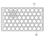
도 1은 일 구현예에 따른 전기 전도성 복합막의 개략도이고,
도 2는 일 구현예에 따른 전기 전도성 복합막의 양 면 중 어느 한 면에서 바라본 평면도이고,
도 3은 일 구현예에 따른 전기 전도성 복합막의 제조 공정을 설명하기 위한 공정도이고,
도 4는 전자 전도성 입자가 막 기재 형성층에 가장 밀집한 구조를 갖도록 배치할 경우를 나타낸 개략도이고,
도 5는 일 구현예에 따른 전기 전도성 복합막 내 전자 전도성 입자의 표면 노출 여부를 전자 전도성 입자 직경-막 기재 형성층의 가압 전 두께 관계와 함께 나타낸 그래프이고,
도 6은 일 구현예에 따른 전기 전도성 복합막을 포함하는 이차전지를 나타낸 개략도이고,
도 7은 일 구현예에 따른 전기 전도성 복합막을 포함하는 전자기기를 나타낸 개략도이고,
도 8은 비교예 4에 따른 전기 전도성 복합막의 하부면을 나타낸 SEM 이미지이고,
도 9 내지 도 10은 실시예 13에 따른 전기 전도성 복합막의 상부면(도 9)과 하부면(도 10)을 나타낸 SEM 이미지이고,
도 11 내지 도 12는 비교예 14에 따른 전기 전도성 복합막의 상부면(도 11)과 하부면(도 12)을 나타낸 SEM 이미지이다.1 is a schematic diagram of an electrically conductive composite membrane according to one embodiment,
2 is a plan view seen from either side of both sides of an electrically conductive composite membrane according to one embodiment,
3 is a process diagram for explaining the manufacturing process of the electrically conductive composite membrane according to one embodiment,
Figure 4 is a schematic diagram showing a case where the electron conductive particles are arranged to have the most dense structure on the film base layer,
5 is a graph showing whether the surface of the electron-conducting particles in the electrically-conductive composite film according to an embodiment is exposed together with the thickness of the electron-conducting particle diameter-thickness of the film substrate forming layer,
6 is a schematic view showing a secondary battery including an electrically conductive composite membrane according to one embodiment,
7 is a schematic diagram showing an electronic device including an electrically conductive composite membrane according to one embodiment,
8 is a SEM image showing the lower surface of the electrically conductive composite film according to Comparative Example 4,
9 to 10 are SEM images showing an upper surface (FIG. 9) and a lower surface (FIG. 10) of the electrically conductive composite film according to Example 13,
11 to 12 are SEM images showing an upper surface (FIG. 11) and a lower surface (FIG. 12) of the electrically conductive composite film according to Comparative Example 14.
이하, 실시예에 대하여 본 기술분야에서 통상의 지식을 가진 자가 용이하게 실시할 수 있도록 상세히 설명한다. 그러나 여러 가지 상이한 형태로 구현될 수 있으며 여기에서 설명하는 실시예에 한정되지 않는다.Hereinafter, embodiments will be described in detail so that those skilled in the art can easily implement them. However, it can be implemented in many different forms and is not limited to the embodiments described herein.
도면에서 여러 층 및 영역을 명확하게 표현하기 위하여 두께를 확대하여 나타내었다. 명세서 전체를 통하여 유사한 부분에 대해서는 동일한 도면 부호를 붙였다. 층, 막, 영역, 판 등의 부분이 다른 부분 "위에" 있다고 할 때, 이는 다른 부분 "바로 위에" 있는 경우 뿐만 아니라 그 중간에 또 다른 부분이 있는 경우도 포함한다. 반대로 어떤 부분이 다른 부분 "바로 위에" 있다고 할 때에는 중간에 다른 부분이 없는 것을 뜻한다.In the drawings, thicknesses are enlarged to clearly represent various layers and regions. The same reference numerals are used for similar parts throughout the specification. When a portion of a layer, film, region, plate, etc. is said to be “above” another portion, this includes not only the case “directly above” the other portion but also another portion in between. Conversely, when one part is "just above" another part, it means that there is no other part in the middle.
또한, 본 기재에서 입자의 입경에 관해서는, 계측법에 의해 수치화하여 집단의 평균 크기를 표현하는 방법이 있지만, 범용적으로 사용되는 것으로 분포의 최대값을 나타내는 모드 직경, 적분 분포 곡선의 중앙값에 상당하는 메디안 직경, 각종 평균 직경(수평균, 길이 평균, 면적 평균, 질량 평균, 체적 평균 등)등이 있고 본 발명에 있어서는 특별히 언급하지 않는 한 평균 입경이란 수평균 직경이고, D50(분포율이 50% 되는 지점의 입경)을 측정한 것을 의미한다.In addition, in the present description, there is a method of expressing the average size of the population by digitizing with a measurement method for the particle diameter of the particles, but it is used universally and corresponds to the median value of the mode diameter and the integral distribution curve indicating the maximum value of the distribution. There are various median diameters, various average diameters (number average, length average, area average, mass average, volume average, etc.) and the average particle diameter is the number average diameter and D50 (distribution ratio is 50%) unless otherwise specified in the present invention. It means the measurement of the particle size of the point.
본 기재에서 전기 전도성이란, 전하를 띄는 캐리어(carrier) 가 이동하여 접촉한 두 구성요소 사이에 전류가 흐르도록 하는 성질을 의미한다. 상기 캐리어의 예시로는 전자, 이온 등을 들 수 있다.In the present description, electrical conductivity refers to a property in which a carrier carrying a charge moves so that an electric current flows between two contacted components. Examples of the carrier include electrons and ions.
이차전지 및/또는 전자기기에 있어 특정 캐리어(예를 들어 리튬 이온 등의 이온이나 전자)만을 선택적으로 전도하기 위한 전기 전도막은, 대면적으로 가공 가능할 정도의 가공성, 기계적인 유연성, 상기 캐리어에 대한 높은 전도성, 및 물, 산소, 이산화탄소 등 반응성 물질에 대한 배리어성이 모두 요구된다. In a secondary battery and/or an electronic device, an electrically conductive film for selectively conducting only a specific carrier (for example, ions or electrons such as lithium ions) has a processability to a large area, mechanical flexibility, and flexibility for the carrier. High conductivity and barrier properties to reactive materials such as water, oxygen and carbon dioxide are all required.
그러나, 기존에 전기 전도막으로 사용되는 소재들 중, 상기 물성을 모두 만족하는 소재는 존재하지 않는다. 기존에 사용되던 소재들로는 유기 겔, 유기 폴리머, 무기 비산화물, 세라믹 글래스 등이 있다.However, among the materials used as the electrically conductive film, there is no material that satisfies all the above properties. Materials used in the past include organic gels, organic polymers, inorganic non-oxides, and ceramic glass.
예를 들어 유기 겔의 경우, 기계적인 강도가 약하고 기체에 취약하며, 전기 전도성을 나타내지 않는다. 유기 폴리머의 경우 기계적 강도 및 유연성이 우수한 편이고, 기체에 대한 배리어성 또한 우수한 편이나, 전기 전도성을 나타내지 않는다. 무기 비산화물의 경우는 전기 전도성이 양호한 편이지만, 흡습성을 가지며, 산소 등과도 반응할 수 있어 배리어성을 만족시키지 못한다. 세라믹 글라스의 경우는 전기 전도성이 우수한 편이지만, 세라믹 특성 상 취성이 강하므로 기계적 강도와 유연성이 낮고, 두께를 증가시키지 않으면 대면적화하기 어렵다.For example, in the case of organic gels, the mechanical strength is weak, the gas is vulnerable, and does not exhibit electrical conductivity. In the case of an organic polymer, mechanical strength and flexibility are excellent, and a barrier property to a gas is also excellent, but does not show electrical conductivity. In the case of the inorganic non-oxide, electrical conductivity is good, but it has hygroscopicity and can react with oxygen and the like, and thus does not satisfy barrier properties. In the case of ceramic glass, electrical conductivity tends to be excellent, but due to the characteristics of ceramics, it has low brittleness and low mechanical strength and flexibility, and it is difficult to increase the area without increasing the thickness.
상기 기존 소재들을 대체하기 위한 방안으로, 유기/무기 또는 유기/무기/금속 하이브리드 전기 전도막이 제안되었다. 상기 유기/무기 하이브리드 전기 전도막은 무기 또는 무기/금속 하이브리드 전기 전도재료를 통해 열안정성과 전기 전도성을 확보하고, 유기 폴리머를 통해 가공성, 유연성, 기타 기계적 물성을 확보한다. As a method to replace the existing materials, an organic/inorganic or organic/inorganic/metal hybrid electrical conductive film has been proposed. The organic/inorganic hybrid electrical conductive film secures thermal stability and electrical conductivity through an inorganic or inorganic/metal hybrid electrical conductive material, and secures processability, flexibility, and other mechanical properties through an organic polymer.
그러나 상기 유기/무기 또는 유기/무기/금속 하이브리드 전기 전도막은 막 형성 시 습식(wet) 공정을 이용한다. 따라서 유기 폴리머를 도포 후 잔여 유기 폴리머 부분을 에칭하여 제거하는 등의 공정을 거쳐야 하므로 대량 생산성을 확보하기 어렵다. However, the organic/inorganic or organic/inorganic/metal hybrid electrical conductive film uses a wet process when forming a film. Therefore, it is difficult to secure mass productivity since a process such as etching and removing the remaining organic polymer portion is required after applying the organic polymer.
이를 개선하기 위한 방안으로 진공 조건 하에서 무기 또는 무기/금속 하이브리드 전기 전도재료의 배치 및 유기 폴리머의 도포, 및 건조 공정 중 그리드(grid)를 배치하는 방안을 고려해 볼 수도 있으나, 그리드 아래로 유기 폴리머의 침투가 잘 이루어지지 않을 수도 있으며, 상기 전기 전도재료가 유기 폴리머에 의해 덮혀져 버릴 우려도 있다. 따라서, 이와 같은 제조 방법은 전체 공정 조건을 제어하기 까다롭고, 대량생산성에도 적합하지 않다.As a method to improve this, it is possible to consider the arrangement of the inorganic or inorganic/metal hybrid electrical conductive material under vacuum conditions, the application of the organic polymer, and the arrangement of the grid during the drying process. It may not be well penetrated, there is a fear that the electrically conductive material is covered with an organic polymer. Therefore, such a manufacturing method is difficult to control the overall process conditions, and is not suitable for mass productivity.
한편, 다른 개선 방안으로 열가소성 유기 폴리머에 상기 전도 재료를 배치하고 양 면을 가압하는 방안을 고려해 볼 수도 있으나, 열가소성 유기 폴리머는 너무 유연하여 가압 후 박리가 어렵고, 보이드(void), 크랙(crack) 등의 막 내부 및/또는 표면 결함이 발생할 가능성이 있다. On the other hand, as another improvement method, a method of disposing the conductive material on the thermoplastic organic polymer and pressing both sides may be considered, but the thermoplastic organic polymer is too flexible to peel after pressing, and voids and cracks There is a possibility of defects in the inner and/or surface of the film.
따라서, 가공성과 유연성 및 배리어성이 모두 우수하면서도, 간단한 방법을 이용하여 제조할 수 있어 대량 생산성을 구비한 전기 전도성 복합막의 필요성이 증대되고 있다.Accordingly, there is an increasing need for an electrically conductive composite film having both mass productivity and being able to be manufactured using a simple method while being excellent in both processability, flexibility, and barrier properties.
일 구현예에 따르면, 상기 가공성, 유연성 및 배리어성을 모두 가지면서도, 기존 제조 공정들 대비 복잡한 공정 조건 제어 없이도 간단하게 제조 가능하여 대량 생산성을 갖춘 전기 전도성 복합막, 및 그 제조 방법을 제공할 수 있다.According to one embodiment, while having all of the processability, flexibility and barrier properties, it is possible to provide an electrically conductive composite membrane having mass productivity by simply manufacturing without complicated process condition control compared to existing manufacturing processes, and a method for manufacturing the same have.
이하, 일 구현예에 따른 전기 전도성 복합막의 구성을 설명한다.Hereinafter, the configuration of the electrically conductive composite membrane according to one embodiment will be described.
도 1은 일 구현예에 따른 전기 전도성 복합막의 개략도이다.1 is a schematic diagram of an electrically conductive composite membrane according to one embodiment.
도 1을 참고하면, 일 구현예에 따른 전기 전도성 복합막(10)은 경화성 재료를 포함하는 고체 막 기재(110), 및 상기 고체 막 기재(110)에 배치되어 있는 전기 전도성 입자(120)를 포함한다.Referring to FIG. 1, the electrically conductive
일 구현예에서, 상기 전기 전도성 입자(120)는 상기 고체 막 기재(110)의 양 면으로 각각 노출되어 있을 수 있다. 즉, 상기 전기 전도성 입자(120)는 상기 고체 막 기재(110)의 대향하는 양 면 (도 1 기준, 막 기재의 상부면과 하부면) 각각으로 노출되어 있을 수 있다.In one embodiment, the electrically
전기 전도성 복합막 중 이온 전도막의 경우, 이차전지의 양극과 음극 사이에 배치되며, 상기 대향면은 상기 양극, 음극과 각각 마주보도록 배치된다. 따라서, 양극과 음극 사이에서 이러한 이온 전도막이 수분 등을 차단하되, 이온(예를 들어 리튬 이온 등)만 선택적으로 통과시키기 위해서는 이온 전도성을 갖는 부분이 이온 전도막의 양 면에 노출될 필요가 있다. In the case of the ion conductive film of the electrically conductive composite film, it is disposed between the positive electrode and the negative electrode of the secondary battery, and the opposite surfaces are disposed to face the positive electrode and the negative electrode, respectively. Therefore, between the positive electrode and the negative electrode, such an ion-conducting film blocks moisture and the like, but in order to selectively pass only ions (for example, lithium ions), it is necessary that portions having ion conductivity are exposed on both sides of the ion-conducting film.
한편, 전기 전도성 복합막 중 전자 전도막의 경우, 전자기기 내 두 구성요소들, 예컨대 상기 패널과 구동 집적 회로를 서로 연결하도록 배치된다. 이 경우, 전자 전도막은 패널과 구동 집적 회로와 각각 접속된 부분은 서로 물리적/전기적으로 연결시켜주되, 그 외 전자 전도막과 접촉하는 다른 부분이나 인접한 구성요소들과의 관계는 전기적으로 절연되어야 할 필요가 있다. On the other hand, in the case of the electronic conductive film of the electrically conductive composite film, two components in the electronic device, for example, the panel and the driving integrated circuit are arranged to connect each other. In this case, the electronic conductive film is connected to the panel and the driving integrated circuit, respectively, and the parts connected to each other are physically and electrically connected to each other, but the relationship with other parts or adjacent components that are in contact with the electronic conductive film should be electrically insulated. There is a need.
단, 일 구현예에 따른 전기 전도성 복합막(10)은 전술한 바와 같이 전기 전도성 입자(120)가 고체 막 기재(110)의 양 면으로 각각 노출되어 있으므로, 이를 통해 일 구현예에 따른 전기 전도성 복합막(10)이 이온 및/또는 전자만을 선택적으로 통과시키는 기능을 수행할 수 있다.However, in the electrically conductive
일 구현예에서, 고체 막 기재(110)는 전기 전도성 입자(120)와의 관계에서 전기 전도성 입자(120)의 배열을 유지할 수 있다. 일 구현예에서, 고체 막 기재(110)는 절연성을 가질 수 있다. 이에 따라 고체 막 기재(110)가 형성된 부분은 이온 및/또는 전자의 교환을 차단하되, 전기 전도성 입자(120)를 통해 선택적으로 이온 및/또는 전자가 통과될 수 있다.In one embodiment, the
고체 막 기재(110)는 전기 전도성 입자(120)를 제외한 다른 부분에서 불필요하게 이온 및/또는 전자가 통과되지 못하도록 전기적으로 절연성을 가질 수 있다. 또한, 고체 막 기재(110)는 수분, 산소, 이산화탄소 등 기체들에 대한 배리어성을 가질 수 있다.The
일 구현예에서, 고체 막 기재(110)는 상기 경화성 재료를 포함할 수 있다. 일 구현예에서, 상기 경화성 재료는 고체 막 기재(110)를 이루고 있는 주요 성분이다. 이에 따라, 고체 막 기재(110)가 경화 공정을 통해 고체 상을 공고히 유지할 수 있다. In one embodiment, the
예를 들어, 고체 막 기재(110)는 상기 경화성 재료로 이루어진 것일 수 있으나, 경우에 따라 상기 경화성 재료를 주 성분으로 하되 추가로 중합 개시제 등 공지된 다양한 유/무기물들을 더 포함할 수도 있다. For example, the
또한, 상기 경화성 재료는 고체 막 기재(110)에 적절한 수준의 유연성(flexibility)을 부여하면서도, 열가소성 재료 대비 막 자체의 결함 (보이드, 크랙 등)의 발생 확률을 크게 낮추어 줄 수 있다.In addition, while the curable material imparts an appropriate level of flexibility to the
일 구현예에서, 상기 경화성 재료는 경화를 통해 고체 상을 갖게 되는 재료이면 무방하며, 구체적인 경화 방법 등으로 제한되는 것은 아니다. 예를 들어, 상기 경화성 재료로는 열 경화성 재료, 자외선 경화성 재료, 및 습기 경화성 재료 중에서 선택되는 하나 이상을 포함할 수 있다. 일 구현예에서, 경화성 재료는 전술한 열 경화성, 자외선 경화성, 습기 경화성 중 서로 다른 경화성을 갖는 2종 이상의 재료를 포함할 수 있다. In one embodiment, the curable material may be any material that has a solid phase through curing, and is not limited to a specific curing method or the like. For example, the curable material may include at least one selected from heat curable materials, ultraviolet curable materials, and moisture curable materials. In one embodiment, the curable material may include two or more materials having different curability among the above-described heat curable, ultraviolet curable, and moisture curable.
상기 경화성 재료의 구체적인 예시로는 아크릴계 화합물, 에폭시계 화합물, 우레탄계 화합물, 페놀계 화합물, 또는 이들의 조합을 들 수 있다. Specific examples of the curable material include acrylic compounds, epoxy compounds, urethane compounds, phenol compounds, or combinations thereof.
예를 들어, 경화성 재료로는 아크릴계 화합물을 사용할 수 있다. 비제한적인 예시로, 아크릴계 화합물은 아크릴기 외에 내부에 다양한 가교기들을 1종 이상 포함하고 있을 수도 있다. 상기 가교기의 예시로는 이소시아네이트기, 디이소시아네이트기, 말레이미드기 등을 들 수 있다. For example, an acrylic compound can be used as the curable material. As a non-limiting example, the acrylic compound may include one or more various crosslinking groups therein in addition to the acrylic group. Examples of the crosslinking group include an isocyanate group, a diisocyanate group, and a maleimide group.
한편, 상기 경화성 재료는 소정의 탄성을 가지고 있을 수 있다. 상기 탄성은 온도 변화에 따라 달라질 수는 있으나, 상기 경화성 재료의 탄성에 의하여 경화가 완료되어 고체 상을 갖게 된 고체 막 기재(110)의 상온(25 ℃)에서의 탄성률은 예를 들어 10 MPa 이상, 예를 들어 20 MPa 이상, 예를 들어 30 MPa 이상, 예를 들어 40 MPa 이상, 예를 들어 50 MPa 이상, 예를 들어 60 MPa 이상이고, 예를 들어 1000 MPa 이하, 예를 들어 900 MPa 이하, 예를 들어 800 MPa 이하, 예를 들어 700 MPa 이하, 예를 들어 600 MPa 이하, 예를 들어 500 MPa 이하, 예를 들어 400 MPa 이하, 예를 들어 300 MPa 이하, 예를 들어 200 MPa 이하, 예를 들어 100 MPa 이하이며, 예를 들어 10 MPa 내지 1000 MPa, 예를 들어 20 MPa 내지 1000 MPa, 예를 들어 30 MPa 내지 1000 MPa, 예를 들어 30 MPa 내지 900 MPa, 예를 들어 40 MPa 내지 800 MPa, 예를 들어 40 MPa 내지 700 MPa, 예를 들어 40 MPa 내지 600 MPa, 예를 들어 40 MPa 내지 500 MPa, 예를 들어 40 MPa 내지 400 MPa, 예를 들어 50 MPa 내지 300 MPa, 예를 들어 50 MPa 내지 200 MPa 일 수 있다. 상기 경화성 재료의 경화 후 탄성률이 전술한 범위를 만족할 경우, 고체 막 기재(110)가 적정 수준의 탄성과 유연성을 모두 갖게 될 수 있다. On the other hand, the curable material may have a predetermined elasticity. The elasticity may vary depending on the temperature change, but the elastic modulus at room temperature (25° C.) of the
한편, 상기 경화성 재료의 경화 전 탄성률 또한 온도 변화에 따라 달라질 수 있다. 예컨대, 상기 경화성 재료는 상온(25 ℃)에서 예를 들어 200 kPa 이하, 예를 들어 190 kPa 이하, 예를 들어 180 kPa 이하, 예를 들어 170 kPa 이하, 예를 들어 160 kPa 이하일 수 있으며, 상온보다 다소 높은 온도, 예컨대 50 ℃ 내지 200 ℃ 의 온도 구간에서 예를 들어 100 kPa 이하, 예를 들어 90 kPa 이하의 탄성률을 가질 수 있다. 경화성 재료의 경화 전 탄성률이 전술한 범위를 만족하는 경우, 후술할 전기 전도성 입자(120)를 막 기재 형성층에 용이하게 배치할 수 있다. On the other hand, the elastic modulus before curing of the curable material may also be changed according to a temperature change. For example, the curable material may be, for example, 200 kPa or less at room temperature (25° C.), for example, 190 kPa or less, for example 180 kPa or less, for example 170 kPa or less, for example 160 kPa or less, It may have an elastic modulus of, for example, 100 kPa or less, for example, 90 kPa or less, at a slightly higher temperature, for example, in a temperature range of 50°C to 200°C. When the elastic modulus before curing of the curable material satisfies the above-described range, the electrically
한편, 상기 경화성 재료는 점착성을 가지고 있을 수 있다. 상기 경화성 재료가 점착성을 더 가질 경우, 후술할 전기 전도성 입자(120)가 상기 경화성 재료를 포함하는 막 기재 형성층에 소정의 배열을 이루도록 배치될 수 있다. 상기 전기 전도성 입자(120)의 구체적인 배열에 대해서는 후술한다.Meanwhile, the curable material may have adhesive properties. When the curable material further has an adhesive property, the electrically
한편, 일 구현예에서 전기 전도성 입자(120)가 고체 막 기재(110) 양 면에 각각 노출될 수 있기 위해서는, 고체 막 기재(110)의 두께가 적어도 전기 전도성 입자(120)의 직경 이하일 필요가 있다.On the other hand, in one embodiment, in order for the electrically
예를 들어, 고체 막 기재(110)는 전기 전도성 입자(120)의 직경의 90% 이하, 예를 들어 80% 이하, 예를 들어 70% 이하, 예를 들어 60% 이하, 예를 들어 50% 이하, 예를 들어 40% 이하의 두께를 가질 수 있고, 예를 들어 적어도 20% 이상, 예를 들어 30% 이상의 두께를 가질 수 있다. 고체 막 기재(110)가 전술한 범위를 만족할 경우, 전기 전도성 복합막(10)이 우수한 전기 전도성, 기계적 강도, 및 배리어성을 나타낼 수 있다.For example, the
일 구현예예서, 전기 전도성 입자(120)는 전술한 바와 같이 전기 전도성 복합막(10)의 양 면으로 이온 및/또는 전자를 이동시키는 기능을 수행한다. 일 구현예에 따르면 전기 전도성 입자(120)가 고체 막 기재(110) 양 면으로 노출되어야 전기 전도성을 가질 수 있으므로, 전기 전도성 입자(120)는 모노 레이어로 구성되는 것이 바람직하다.In one embodiment, the electrically
도 2는 일 구현예에 따른 전기 전도성 복합막의 양 면 중 어느 한 면에서 바라본 평면도이다.2 is a plan view viewed from either side of both sides of an electrically conductive composite membrane according to one embodiment.
도 2를 참조하면, 전기 전도성 입자(120)는 고체 막 기재(110)에서 소정의 배열을 이루도록 배치되어 있을 수 있다. 예를 들어, 상기 전도성 입자(120)는 육각 형태로 배열되어 있을 수 있다. Referring to FIG. 2, the electrically
일 구현예에서, 상기 소정의 배열은 전기 전도성 입자(120)가 최대한 밀집하도록 배치된 배열일 수 있다. 예컨대, 전기 전도성 입자(120)는 육각 밀집(hexagonal close-packed) 형태의 배열을 이루고 있을 수 있다. 이 경우, 단위 체적 당 전기 전도성 입자(120)가 차지하는 체적이 증가함으로써, 전기 전도성 복합막(10)의 양 면으로 노출되는 전기 전도성 입자(120)의 면적도 증가하게 된다. 그 결과, 전기 전도성이 향상된 전기 전도성 복합막(10)을 제공할 수 있다. In one embodiment, the predetermined arrangement may be an arrangement in which the electrically
다만, 전기 전도성 입자(120)의 구체적인 배치나 배열이 전술한 바에 한정되는 것은 아니며, 전기 전도성 입자(120)가 고체 막 기재(110)의 양 면에 각각 노출된다는 조건 하에 전기 전도성 입자(120)의 종류, 전기 전도성 복합막(10)의 적용 분야, 고체 막 기재(110)를 이루는 경화성 재료의 소재, 및 점착 강도(또는 박리 강도) 등에 따라 다양한 배열이나 배치를 이루고 있을 수도 있다.However, the specific arrangement or arrangement of the electrically
일 구현예에서, 전기 전도성 입자(120)는 이온 전도성 입자, 전자 전도성 입자, 또는 이들의 조합을 포함할 수 있다. 일 구현예에서, 전기 전도성 입자(120)가 이온 전도성 입자를 포함하는 경우 전기 전도성 복합막(10)이 이온 전도성을 나타내고, 전자 전도성 입자를 포함하는 경우 전기 전도성 복합막(10)이 전자 전도성을 나타낼 수 있다.In one embodiment, the electrically
전기 전도성 복합막(10)이 이온 전도성을 나타낼 경우, 전기 전도성 입자(120)는 예를 들어 리튬 이온, 나트륨 이온, 수소 이온, 칼륨 이온, 철 이온, 아연 이온, 마그네슘 이온, 칼륨 이온 중 적어도 하나의 이온을 전도할 수 있는 것일 수 있다.When the electrically conductive
일 구현예에서, 상기 전기 전도성 입자(120)는 전술한 이온에 대하여, 적어도 10-6 S/cm 이상, 예를 들어 10-5 S/cm 이상의 이온 전도성을 나타낼 수 있고, 예를 들어 1×10⁻³ S/cm 이하, 예를 들어 1×10⁻⁴ S/cm 이하의 이온 전도성을 나타낼 수 있으며, 예를 들어 1×10⁻⁵ S/cm 내지 1×10⁻³ S/cm, 예를 들어 1×10⁻⁴ S/cm 가량의 이온 전도성을 나타낼 수 있다. 일 구현예에서, 상기 범위의 이온 전도성은 리튬 이온에 대한 이온 전도성일 수 있다. 다만, 일 구현예가 반드시 이에 제한되는 것은 아니며, 전술한 종류의 이온들에 대해서도 전술한 범위 내의 우수한 이온 전도성을 나타낼 수 있다.In one embodiment, the electrically
일 구현예에서, 상기 전기 전도성 입자(120)는 황화물, 산화물, 또는 이들의 조합을 포함할 수 있다. In one embodiment, the electrically
일 구현예에서 황화물이란 황 원소가 금속, 산소, 탄화수소 등과 결합하여 형성된 물질을 폭넓게 일컫는다. In one embodiment, sulfide refers to a material in which sulfur is formed by combining metal, oxygen, hydrocarbons, and the like.
일 구현예에서 산화물이란 산소 원소가 금속, 탄화수소 등과 결합하여 형성된 물질을 폭넓게 일컫는다. 일 구현예에서, 상기 산화물의 구체예로는 ZrO2, AlO3, 및 하기 화학식 1 내지 화학식 4 로 표현되는 화합물을 들 수 있다. 즉, 일 구현예에 따른 상기 전기 전도성 입자(120)는 ZrO2, AlO3, 및 하기 화학식 1 내지 화학식 4 로 표현되는 화합물 중 적어도 하나를 포함하는 것일 수 있다. In one embodiment, the oxide refers to a material formed by combining oxygen elements with metals, hydrocarbons, and the like. In one embodiment, specific examples of the oxide include ZrO 2 , AlO 3 , and compounds represented by Formulas 1 to 4 below. That is, the electrically
[화학식 1][Formula 1]
Li3La(2/3-x)TiO3 Li 3 La (2/3-x) TiO 3
[화학식 2][Formula 2]
LiyLa3M1 2O12 Li y La 3 M 1 2 O 12
[화학식 3][Formula 3]
Li(2-2z)Zn(1-z)GeO4 Li (2-2z) Zn (1-z) GeO 4
[화학식 4][Formula 4]
LiM2 2(PO4)3 LiM 2 2 (PO 4 ) 3
상기 화학식 1 내지 화학식 4에서,In Chemical Formulas 1 to 4,
M1은 지르코늄(Zr), 니오븀(Nb), 탄탈륨(Ta), 안티몬(Sb), 및 비스무트(Bi) 중에서 선택되는 하나 이상의 원소이고,M 1 is one or more elements selected from zirconium (Zr), niobium (Nb), tantalum (Ta), antimony (Sb), and bismuth (Bi),
M2는 저머늄(Ge), 티타늄(Ti), 하프늄(Hf), 및 지르코늄(Zr) 중에서 선택되는 하나 이상의 원소이고,M 2 is one or more elements selected from germanium (Ge), titanium (Ti), hafnium (Hf), and zirconium (Zr),
0 ≤ x ≤ 2/3, 5 ≤ y ≤ 7, 및 0 ≤ z < 1 이다.0 ≤ x ≤ 2/3, 5 ≤ y ≤ 7, and 0 ≤ z <1.
전기 전도성 입자(120)는 전도 대상 이온의 종류에 따라 전술한 화학식 1 내지 화학식 4로 표현되는 화합물 중 어느 하나만을 사용할 수도 있고, 이들을 2 이상 혼합하여 사용할 수도 있다.The electrically
한편, 전기 전도성 복합막(10)이 전자 전도성을 나타낼 경우, 전기 전도성 입자(120)는 예를 들어 탄성체, 및 상기 탄성체 표면에 형성된 금속층을 포함하고 있을 수 있다. 예를 들어, 상기 전기 전도성 입자(120)는 탄성체로 이루어진 코어 표면에 금속 쉘층이 형성된 코어-쉘 구조를 가질 수 있다. Meanwhile, when the electrically conductive
상기 탄성체는 소정의 탄성을 가지는 재료면 특별히 제한되지 않으나, 예를 들어 폴리스티렌계 화합물, 에폭시계 화합물, 폴리이미드계 화합물, 페놀계 화합물, 또는 이들의 조합을 포함할 수 있다. The elastic body is not particularly limited as long as it has a material having a predetermined elasticity, but may include, for example, a polystyrene-based compound, an epoxy-based compound, a polyimide-based compound, a phenol-based compound, or a combination thereof.
상기 탄성체 표면에 형성되는 금속층은 전기 전도성 입자(120)에 소정의 전기 전도성을 부여한다. 상기 금속층은 단일 층일 수도 있고, 2 이상의 다중 층일 수도 있다. The metal layer formed on the surface of the elastic body imparts a predetermined electrical conductivity to the electrically
예를 들어, 금속층에 포함되는 금속으로는 예를 들어 금(Au), 은(Ag), 니켈(Ni), 팔라듐(Pd), 구리(Cu), 또는 이들의 조합을 포함할 수 있다. 상기 금속은 단일 금속일 수도 있고, 전술한 금속의 2 이상의 얼로이일 수도 있다.For example, the metal included in the metal layer may include, for example, gold (Au), silver (Ag), nickel (Ni), palladium (Pd), copper (Cu), or a combination thereof. The metal may be a single metal, or may be two or more alloys of the aforementioned metals.
한편, 금속층이 2 이상의 다중층일 경우, 2 이상의 층은 서로 다른 금속을 포함하고 있을 수 있다. On the other hand, when the metal layer is a multiple layer of two or more, the two or more layers may include different metals.
예를 들어, 상기 전기 전도성 입자(120)는 에폭시계 화합물과 페놀계 화합물을 포함하는 탄성체의 표면에 니켈층과 금층이 순차 형성된 것일 수 있다. For example, the electrically
다만, 일 구현예가 이에 제한되는 것은 아니고, 전기 전도성 입자(120)에 요구되는 전기 전도성 정도에 따라 금속의 종류, 층 수 등을 다양하게 변형 가능하다.However, one embodiment is not limited thereto, and various types of metals, number of layers, and the like may be modified according to the degree of electrical conductivity required for the electrically
일 구현예에 다른 전기 전도성 복합막(10)은 고체 막 기재(110)의 두께와 전기 전도성 입자(120)의 직경, 및/또는 소재 등에 따라 달라질 수 있지만, 예를 들어 5 ㎛ 이상, 예를 들어 10 ㎛ 이상, 예를 들어 15 ㎛ 이상, 예를 들어 20 ㎛ 이상의 두께를 가질 수 있고, 예를 들어 50 ㎛ 이하, 예를 들어 45 ㎛ 이하, 예를 들어 40 ㎛ 이하, 예를 들어 35 ㎛ 이하, 예를 들어 30 ㎛ 이하, 예를 들어 25 ㎛ 이하의 두께를 가질 수 있으며, 예를 들어 5 ㎛ 내지 50 ㎛, 예를 들어 20 ㎛ 내지 90 ㎛ 의 두께를 가질 수 있다.The electrically conductive
일 구현예에 따른 전기 전도성 복합막(10)이 전술한 범위 내의 두께를 가질 경우, 기계적 강도와 배리어성이 우수하면서도 유연성과 가공성을 우수하게 유지할 수 있다. When the electrically conductive
이상에서 살펴본 바와 같이, 일 구현예에 따른 전기 전도성 복합막(10)은 막의 양 면으로 노출된 전기 전도성 입자(120)를 통해 이온 및/또는 전자의 이동이 가능하며, 나머지 수분, 산소, 이산화탄소 등 물질의 이동을 차단할 수 있다. 또한, 일 구현예에 따른 전기 전도성 복합막(10)은 고체 막 기재(110)의 두께와 전기 전도성 입자(120) 직경간의 관계를 규정함으로써 우수한 기계적 강도와 유연성, 및 배리어성을 확보할 수 있으며, 전기 전도성 입자(120)에 기인한 우수한 전기 전도성을 함께 나타낼 수 있다.As described above, the electrically conductive
이하, 일 구현예에 따른 전기 전도성 복합막의 제조 방법을 설명한다.Hereinafter, a method of manufacturing an electrically conductive composite membrane according to one embodiment will be described.
도 3은 일 구현예에 따른 전기 전도성 복합막의 제조 공정을 설명하기 위한 공정도이다.3 is a process diagram for explaining a manufacturing process of an electrically conductive composite membrane according to one embodiment.
일 구현예에 따른 전기 전도성 복합막의 제조 방법은, 막 기재 형성층 위에 상기 전기 전도성 입자를 배치하고, 상기 막 기재 형성층과 상기 전기 전도성 입자를 가압하고, 상기 막 기재 형성층을 경화하는 과정을 포함하여 수행할 수 있다.A method of manufacturing an electrically conductive composite film according to an embodiment is performed by disposing the electrically conductive particles on a film substrate forming layer, pressing the film substrate forming layer and the electrically conductive particles, and curing the film substrate forming layer. can do.
전기 전도성 복합막의 제조 공정은 도 3을 기준으로 좌측에서부터 우측을 향해 순차적으로 진행될 수 있다.The manufacturing process of the electrically conductive composite film may be sequentially performed from left to right based on FIG. 3.
상기 전기 전도성 복합막의 제조 공정은 이송부와 롤에 의해 연속적으로 진행되는 공정을 포함할 수 있다. 이 경우, 막 기재 형성층의 하부면은 하부 이형 기재에 의해 지지되고 있을 수 있다. 상기 하부 이형 기재는 도 3에 나타난 제조 공정과 같이 연속적으로 이송되거나 권취될 수 있는 기재이면 특별히 제한되지 않으며, PET, 및/또는 실리콘 처리된 PET 등의 폴리머 기재일 수 있다.The manufacturing process of the electrically conductive composite film may include a process that is continuously performed by a transfer part and a roll. In this case, the lower surface of the film substrate forming layer may be supported by the lower release substrate. The lower release substrate is not particularly limited as long as it is a substrate that can be continuously transported or wound, such as the manufacturing process shown in FIG. 3, and may be a polymer substrate such as PET, and/or silicone-treated PET.
우선, 전기 전도성 입자 배치 과정에서는 미리 준비된 막 기재 형성층 위에 전기 전도성 입자를 소정의 배열을 갖도록 배치한다. First, in the process of arranging the electrically conductive particles, the electrically conductive particles are disposed on the previously prepared film base layer to have a predetermined arrangement.
우선, 막 기재 형성층의 상부면을 덮고 있는 상부 이형 기재를 박리한다. 상기 상부 이형 기재는 전술한 하부 이형 기재와 마찬가지로 연속적으로 이송되거나 권취될 수 있는 기재이면 특별히 제한되지 않으며, PET, 및/또는 실리콘 처리된 PET 등의 폴리머 기재일 수 있다. 이후, 상부면이 노출된 막 기재 형성층에 전기 전도성 입자를 공급한다. 상기 전기 전도성 입자는, 예를 들어 막 기재 형성층의 상부면으로 산포될 수 있다. 전기 전도성 입자의 산포 과정에서 전기 전도성 입자를 전술한 바와 같이 소정의 배열을 갖도록 배열할 수 있다. First, the upper release substrate covering the upper surface of the film substrate forming layer is peeled off. The upper release substrate is not particularly limited as long as it is a substrate that can be continuously transported or wound like the lower release substrate described above, and may be a polymer substrate such as PET, and/or silicone-treated PET. Subsequently, the electrically conductive particles are supplied to the film base layer on which the upper surface is exposed. The electrically conductive particles may be dispersed, for example, on the upper surface of the film base layer. In the process of dispersing the electrically conductive particles, the electrically conductive particles may be arranged to have a predetermined arrangement as described above.
일 구현예에서 막 기재 형성층은 점착성을 가질 수 있으며, 예를 들어 가압 전인 전기 전도성 입자 배치 과정에서의 막 기재 형성층의 박리 강도는 특별히 제한되지 않으나, 적어도 0.05 N/25mm 이상, 예를 들어 0.5 N/25mm 이상, 예를 들어 1 N/25mm 이상, 예를 들어 2 N/25mm 이상, 예를 들어 3 N/25mm 이상, 예를 들어 4 N/25mm 이상, 예를 들어 5 N/25mm 이상인 것이 바람직하다. 상기 막 기재 형성층의 박리 강도가 전술한 범위를 만족할 경우, 배열된 전기 전도성 입자는 최초 배열된 위치를 이탈하지 않고 유지할 수 있다.In one embodiment, the film substrate forming layer may have adhesiveness, for example, the peel strength of the film substrate forming layer in the process of placing the electrically conductive particles before pressurization is not particularly limited, but is at least 0.05 N/25 mm or more, for example 0.5 N /25mm or more, for example 1 N/25mm or more, for example 2N/25mm or more, for example 3N/25mm or more, for example 4N/25mm or more, for example 5N/25mm or more Do. When the peel strength of the film substrate forming layer satisfies the above-described range, the electrically conductive particles arranged can be maintained without leaving the initially arranged position.
한편, 일 구현예에서 상기 막 기재 형성층은 전기 전도성 입자(120)가 배치됨에 따라, 아르키메데스의 원리에 의해 배치된 전기 전도성 입자의 체적에 해당하는 만큼 초기 두께 대비 두꺼워질 수 있다. 따라서, 일 구현예에서, 상기 막 기재 형성층의 초기 두께는 이 점을 고려하여 미리 소정의 두께로 준비될 수 있다.Meanwhile, in one embodiment, as the electrically
구체적으로, 상기 전기 전도성 입자(120)를 배치하기 전의 상기 막 기재 형성층의 두께를 t라 하고, 상기 전도성 입자(120)의 직경을 D라 하면, 상기 t와 D는 하기 수학식 1의 관계를 만족할 수 있다.Specifically, when the thickness of the film base forming layer before placing the electrically
[수학식 1][Equation 1]
t ≤0.4 x Dt ≤0.4 x D
상기 수학식 1은 하기 산출과정을 통해 얻어질 수 있다. Equation 1 may be obtained through the following calculation process.
도 4는 전자 전도성 입자가 막 기재 형성층에 가장 밀집한 구조를 갖도록 배치할 경우를 나타낸 개략도이다.4 is a schematic view showing a case in which the electron conductive particles are disposed to have the most dense structure on the film substrate forming layer.
우선, 막 기재 형성층에 직경 D의 이상적인 구형 입자인 전기 전도성 입자(120)가 도 4와 같이 이상적인 육각 밀집 형태로 배열한다고 가정한다. 이 경우, 이웃한 두 전기 전도성 입자끼리의 중심을 연결한 거리는 D가 되고, 이웃한 세 전기 전도성 입자끼리의 중심을 연결한 삼각형의 높이는 ![]()
![]()
여기서 전기 전도성 입자를 가로로 N개, 세로로 M개 배열할 경우, 구형 입자의 체적은 하기 수학식 A와 같다.Here, when N electrically conductive particles are arranged horizontally and M vertically, the volume of the spherical particles is as shown in Equation A below.
[수학식 A][Equation A]

한편, 전기 전도성 입자가 배열된 후의 막 기재 형성층의 체적은 하기 수학식 B와 같다.On the other hand, the volume of the film base forming layer after the electrically conductive particles are arranged is as in Equation B below.
[수학식 B][Equation B]

다만, 여기서 막 기재 형성층의 초기 두께 t에 대해, 전기 전도성 입자가 배열된 후의 막 기재 형성층의 두께를 t'라 하면, 상기 t/t'의 관계는 하기 수학식 C를 만족한다.However, if the thickness of the film substrate forming layer after the electrically conductive particles are arranged with respect to the initial thickness t of the film substrate forming layer is t', the relationship between t/t' satisfies Equation C below.
[수학식 C][Equation C]

단, 전기 전도성 입자 배열 후 막 기재 형성층의 두께 t'는 전기 전도성 입자 직경 D을 초과해서는 안되므로, 상기 수학식 C에서 t'에 D를 대입한 후, t와 D의 관계로 정리하면, 전술한 수학식 1이 도출될 수 있다.However, since the thickness t'of the film substrate forming layer after the arrangement of the electrically conductive particles should not exceed the diameter D of the electrically conductive particles, in the equation C, after substituting D for t', the relationship between t and D is summarized above. Equation 1 can be derived.
이후, 전기 전도성 입자가 배열된 막 기재 형성층에 박리해 두었던 상부 이형 필름을 다시 피복한 다음, 석션(suction)을 이용하여 막 기재 형성층에 배열되지 않은 잔여 전기 전도성 입자들을 빨아들여 제거한다. 단, 상기 석션은 전기 전도성 입자의 산포 정도 등에 따라 따라 생략 가능하다. Subsequently, the upper release film that has been peeled off on the membrane substrate forming layer on which the electrically conductive particles are arranged is coated again, and then the remaining electrically conductive particles not arranged on the membrane substrate forming layer are sucked and removed using a suction. However, the suction may be omitted depending on the degree of dispersion of the electrically conductive particles.
도 5는 일 구현예에 따른 전기 전도성 복합막 내 전자 전도성 입자의 표면 노출 여부를 전자 전도성 입자 직경-막 기재 형성층의 가압 전 두께 관계와 함께 나타낸 그래프이다.5 is a graph showing whether the surface of the electron-conducting particles in the electrically-conductive composite film according to an embodiment is exposed together with the thickness of the electron-conductive particle diameter-thickness of the film base layer.
도 5에서는 전자 전도성 입자로 Li1.3Al0.3Ti1.7(PO4)3 (LATP) 입자와 ZrO2 입자를 사용하되, 경화성 소재로 이소시아네이트기를 함유한 아크릴계 점착제를 사용하였으며, 가압 및 가열 시간 조건은 각각 60 MPa, 150 ℃, 3 분이고, 경화 조건(자외선 조사량)은 500 mJ/cm2 이다.In FIG. 5, Li 1.3 Al 0.3 T i1.7 (PO 4 ) 3 (LATP) particles and ZrO 2 particles are used as the electron conductive particles, but an acrylic pressure-sensitive adhesive containing an isocyanate group is used as a curable material. Is 60 MPa, 150° C., and 3 minutes, respectively, and curing conditions (ultraviolet radiation dose) are 500 mJ/cm 2 .
도 5를 참조하면, 전술한 식 1을 만족하지 않을 경우 전기 전도성 입자가 고체 막 기재에 파묻히거나(sinking), 어느 한 면만 노출 (one side only)되는 것을 확인할 수 있다. 또한, 전기 전도성 복합막 양 면이 노출(both side)되는 시점은 전기 전도성 입자의 종류에 따라 다소 다르지만, 공통적으로 전술한 식 1을 만족하는 경우부터 전자 전도성 입자가 안정적으로 고체 막 기재의 양 면으로 노출될 수 있는 것을 확인할 수 있다.Referring to FIG. 5, it can be confirmed that when the above-mentioned Equation 1 is not satisfied, the electrically conductive particles are buried in a solid membrane substrate or exposed on one side only. In addition, the time when both sides of the electrically conductive composite film are exposed (both side) is somewhat different depending on the type of the electrically conductive particles, but the electron conductive particles are stably both sides of the solid film substrate from the case where Equation 1 is satisfied in common. It can be confirmed that can be exposed.
이후, 전기 전도성 입자가 배열된 막 기재 형성층의 양 면을 가압 수단을 이용해 가압하는 과정을 수행할 수 있다.Thereafter, a process of pressing both surfaces of the membrane substrate forming layer on which the electrically conductive particles are arranged may be performed using a pressing means.
일 구현예에서, 상기 가압은 상온보다 높은 온도에서 수행할 수 있다. 구체적으로, 상기 전기 전도성 입자가 배열된 막 기재 형성층의 압밀 시, 상기 막 기재 형성층을 가열할 수 있다. 예를 들어, 전기 전도성 입자가 배열된 막 기재 형성층의 양 면에 생략 가능한 열 전도성 금속판 (예컨대 알루미늄 판)을 배치한 후, 가열 가능한 프레스 등으로 함께 가압하는 동시에, 소정의 온도로 가열할 수 있다.In one embodiment, the pressurization may be performed at a temperature higher than room temperature. Specifically, upon compaction of the film substrate forming layer on which the electrically conductive particles are arranged, the film substrate forming layer may be heated. For example, after arranging a thermally conductive metal plate (for example, an aluminum plate) which can be omitted on both sides of the film base forming layer on which the electrically conductive particles are arranged, it can be heated together at a predetermined temperature while being pressed together with a heatable press or the like. .
탄성률이 비교적 높은 소재의 경우, 단순한 가압만으로는 전도성 입자가 상부면과 하부면으로 각각 노출되지 못하고 어느 한 면(특히 하부면)이 고체 막 기재에 의해 덮히게 될 우려가 있다. 그러나, 일 구현예에 따르면, 상기 전기 전도성 입자가 배열된 막 기재 형성층을 가압과 동시에 가열함으로써, 막 기재 형성층의 탄성률을 다소 낮추어 전기 전도성 입자가 양 면에 노출될 수 있도록 할 수 있다. In the case of a material having a relatively high modulus of elasticity, the conductive particles may not be exposed to the upper and lower surfaces by simply pressing, and there is a fear that one surface (especially the lower surface) may be covered by the solid film substrate. However, according to one embodiment, by heating the film-forming layer on which the electrically conductive particles are arranged simultaneously with pressurization, the elastic modulus of the film substrate-forming layer may be lowered to allow the electrically conductive particles to be exposed on both sides.
상기 가압 및 가열된 막 기재 형성층의 탄성률은 포함된 경화성 재료의 종류 등에 따라 달라질 수 있으나, 60 ℃ 내지 250 ℃의 온도에서 예를 들어 100 kPa 이하, 예를 들어 90 kPa 이하의 탄성률을 나타낼 수 있다. 상기 탄성률 범위는 전술한 고체 막 기재(110)의 탄성률 범위 대비 매우 낮은 값이다.The elastic modulus of the pressurized and heated film base layer may vary depending on the type of the curable material included, but may exhibit an elastic modulus of, for example, 100 kPa or less, for example, 90 kPa or less at a temperature of 60°C to 250°C. . The elastic modulus range is a very low value compared to the elastic modulus range of the aforementioned
일 구현예에서, 상기 가압은 적어도 1 MPa 이상, 예를 들어 5 MPa 이상, 예를 들어 10 MPa 이상, 예를 들어 20 MPa 이상, 예를 들어 30 MPa 이상에서 수행할 수 있고, 예를 들어 100 MPa 이하, 예를 들어 90 MPa 이하, 예를 들어 80 MPa 이하, 예를 들어 70 MPa 이하에서 수행할 수 있으며, 예를 들어 1 MPa 내지 100 MPa, 예를 들어 5 MPa 내지 100 MPa, 예를 들어 10 MPa 내지 100 MPa, 예를 들어 20 MPa 내지 100 MPa, 압력으로 수행될 수 있다.In one embodiment, the pressing may be performed at least 1 MPa or more, for example 5 MPa or more, for example 10 MPa or more, for example 20 MPa or more, for example 30 MPa or more, for example 100 MPa or less, for example 90 MPa or less, for example 80 MPa or less, for example 70 MPa or less, for example 1 MPa to 100 MPa, for example 5 MPa to 100 MPa, for example 10 MPa to 100 MPa, for example 20 MPa to 100 MPa, can be performed at a pressure.
상기 가압 공정 중 가압력이 1 MPa 미만일 경우 전기 전도성 입자(120)가 막 상부면과 하부면으로 각각 노출되지 못하고 고체 막 기재(110)에 의해 덮히게 될 우려가 있고, 100 MPa 을 초과할 경우 전기 전도성 입자(120)가 손상될 우려가 있다.When the pressing force during the pressing process is less than 1 MPa, there is a possibility that the electrically
상기 가열은 적어도 상온(25 ℃) 이상의 온도, 예를 들어 50 ℃ 이상, 예를 들어 60 ℃ 이상, 예를 들어 70 ℃ 이상, 예를 들어 80 ℃ 이상에서 수행할 수 있고, 예를 들어 300 ℃ 이하, 예를 들어 250 ℃ 이하, 예를 들어 200 ℃ 이하에서 수행할 수 있으며, 예를 들어 50 ℃ 내지 300 ℃, 예를 들어 50 ℃ 내지 250 ℃, 예를 들어 60 ℃ 내지 250 ℃, 예를 들어 70 ℃ 내지 250 ℃ 예를 들어 80 ℃ 내지 250 ℃, 예를 들어 80 ℃ 내지 200 ℃에서 수행할 수 있다.The heating may be carried out at a temperature of at least room temperature (25 °C) or higher, for example 50 °C or higher, for example 60 °C or higher, for example 70 °C or higher, for example 80 °C or higher, for example 300 °C Below, for example, it may be carried out at 250 °C or less, for example, 200 °C or less, for example, 50 °C to 300 °C, for example, 50 °C to 250 °C, for example, 60 °C to 250 °C, for example For example, it may be performed at 70°C to 250°C, for example, 80°C to 250°C, for example, 80°C to 200°C.
또한, 상기 가열은 예를 들어 10 초 이상, 예를 들어 15 초 이상, 예를 들어 20 초 이상, 예를 들어 30 초 이상, 예를 들어 1 분 이상 수행할 수 있고, 예를 들어 10 분 이하, 예를 들어 9 분 이하, 예를 들어 8 분 이하, 예를 들어 7 분 이하 수행할 수 있으며, 예를 들어 15 초 내지 10 분, 예를 들어 30 초 내지 10 분, 예를 들어 1 분 내지 10 분, 예를 들어 1 분 내지 9 분, 예를 들어 1 분 내지 8 분, 예를 들어 1 분 내지 7 분 수행할 수 있다. In addition, the heating may be performed, for example, 10 seconds or more, for example, 15 seconds or more, for example, 20 seconds or more, for example, 30 seconds or more, for example, 1 minute or more, and for example, 10 minutes or less , For example 9 minutes or less, for example 8 minutes or less, for example 7 minutes or less, for example 15 seconds to 10 minutes, for example 30 seconds to 10 minutes, for example 1 minute to 10 minutes, for example 1 minute to 9 minutes, for example 1 minute to 8 minutes, for example 1 minute to 7 minutes.
전술한 가열 온도 및/또는 시간이 너무 적으면 막 기재 형성층의 탄성률을 전기 전도성 입자(120)가 삽입될 정도로 낮추기 어려울 수 있으므로 전기 전도성 입자(120)가 막 상부면과 하부면으로 각각 노출되지 못하고 고체 막 기재(110)에 의해 덮히게 될 우려가 있고, 너무 많으면 막 기재 형성층 및/또는 전기 전도성 입자(120)가 손상될 우려가 있다. If the above-mentioned heating temperature and/or time is too small, it may be difficult to lower the elastic modulus of the film substrate forming layer to such an extent that the electrically
가압 및 가열이 완료되면, 가압된 막 기재 형성층을 경화 수단을 이용하여 경화한다. 상기 경화 수단은 자외선 경화 수단, 열 경화 수단, 습기 경화 수단, 또는 이들의 조합을 포함할 수 있으며, 막 기재 형성층에 포함된 경화성 재료의 경화성에 따라 상기 경화 수단을 1종 이상 이용할 수 있다. When pressurization and heating are completed, the pressurized film base forming layer is cured using a curing means. The curing means may include an ultraviolet curing means, a thermal curing means, a moisture curing means, or a combination thereof, and one or more of the curing means may be used depending on the curability of the curable material included in the film base layer.
이후, 경화가 완료되면 상부 이형 기재와 하부 이형 기재를 각각 박리함으로써, 일 구현예에 따른 전기 전도성 복합막(10)을 제조할 수 있다. 일 구현예에서 상기 상부 이형 기재와 하부 이형 기재의 박리 순서는 제한되지 않으며, 동시에 박리를 수행할 수도 있다.Subsequently, when curing is completed, the upper release substrate and the lower release substrate are peeled, respectively, to thereby prepare the electrically conductive
한편, 제조된 전기 전도성 복합막(10)은 기계적 강도와 유연성이 우수하므로, 상부/하부 이형 기재 박리 후 권취 롤을 이용하여 권취할 수 있다. On the other hand, the manufactured electrically conductive
이상에서 살펴본 바와 같이, 일 구현예에 따른 전기 전도성 복합막의 제조 방법은 진공 등 분위기 조건을 맞춰야 할 필요가 없으므로 기존 습식 공정 대비 전체적인 공정 조건의 제어가 용이한 것은 물론, 연속적인 공정을 통해 전기 전도성 복합막을 제조할 수 있으므로 대량생산성 또한 우수하다.As described above, the manufacturing method of the electrically conductive composite membrane according to one embodiment does not need to adjust the atmosphere conditions such as vacuum, so that it is easy to control the overall process conditions compared to the existing wet process, and it is also electrically conductive through a continuous process. Since a composite membrane can be produced, mass productivity is also excellent.
이하, 일 구현예에 따른 전기 전도성 복합막을 포함하는 이차전지를 설명한다.Hereinafter, a secondary battery including an electrically conductive composite film according to an embodiment will be described.
도 6은 일 구현예에 따른 전기 전도성 복합막을 포함하는 이차전지를 나타낸 개략도이다.6 is a schematic view showing a secondary battery including an electrically conductive composite membrane according to an embodiment.
도 6을 참고하면, 일 구현예에 따른 이차전지(1)는 양극(11), 음극(12), 양극(11)과 음극(12) 사이에 개재되어 있는 전기 전도성 복합막(10)을 포함한다. Referring to FIG. 6, a secondary battery 1 according to an embodiment includes an
먼저, 음극(12)이 준비된다.First, the
상기 음극(12)으로서 리튬금속 박막이 사용될 수도 있고, 집전체 및 상기 집전체 상에 배치되는 음극활물질층을 포함할 수도 있다. 예를 들어, 상기 음극(12)은 리튬금속 박막이 집전체인 전도성 기판 상에 배치된 상대로 사용될 수 있다. 상기 리튬금속 박막이 집전체와 일체를 형성할 수 있다.A lithium metal thin film may be used as the
상기 음극(12)에서 집전체는 스테인레스 스틸, 구리, 니켈, 철 및 코발트로 이루어진 군에서 선택된 하나일 수 있으나, 반드시 이들로 한정되지 않으며, 당해 기술분야에서 사용될 수 있는 전도성이 우수한 금속성 기판이라면 모두 가능하다. 예를 들어, 집전체는 전도성 산화물 기판, 전도성 고분자 기판 등일 수 있다. 또한, 집전체는 기판 전체가 전도성 재료로 이루어진 구조 외에 절연성 기판의 일 표면 상에 전도성 금속, 전도성 금속산화물, 전도성 고분자가 코팅된 형태 등 다양한 구조를 가질 수 있다. 상기 집전체는 유연성 기판일 수 있다. 따라서, 집전체는 쉽게 굽혀질 수 있다. 또한, 굽혀진 후에, 집전체는 원래 형태로 복원이 용이할 수 있다.The current collector in the
또한, 상기 음극(12)은 리튬금속 외에 다른 음극활물질을 추가적으로 포함할 수 있다. 상기 음극(12)은 리튬금속과 다른 음극활물질의 합금, 리튬금속과 다른 음극활물질의 복합체 또는 리튬금속과 다른 음극활물질의 혼합물일 수 있다.In addition, the
상기 음극(12)에 추가될 수 있는 다른 음극활물질로는 예를 들어, 리튬과 합금 가능한 금속, 전이금속 산화물, 비전이금속산화물 및 탄소계 재료로 이루어진 군에서 선택된 하나 이상을 포함할 수 있다.Other negative electrode active materials that may be added to the
예를 들어, 상기 리튬과 합금가능한 금속은 Si, Sn, Al, Ge, Pb, Bi, Sb Si-Y 합금(상기 Y는 알칼리 금속, 알칼리 토금속, 13족 원소, 14족 원소, 전이금속, 희토류 원소 또는 이들의 조합 원소이며, Si는 아님), Sn-Y 합금(상기 Y는 알칼리 금속, 알칼리 토금속, 13족 원소, 14족 원소, 전이금속, 희토류 원소 또는 이들의 조합 원소이며, Sn은 아님) 등일 수 있다. 상기 원소 Y로는 Mg, Ca, Sr, Ba, Ra, Sc, Y, Ti, Zr, Hf, Rf, V, Nb, Ta, Db, Cr, Mo, W, Sg, Tc, Re, Bh, Fe, Pb, Ru, Os, Hs, Rh, Ir, Pd, Pt, Cu, Ag, Au, Zn, Cd, B, Al, Ga, Sn, In, Ti, Ge, P, As, Sb, Bi, S, Se, Te, Po, 또는 이들의 조합일 수 있다.For example, the metal alloyable with lithium is Si, Sn, Al, Ge, Pb, Bi, Sb Si-Y alloy (where Y is an alkali metal, alkaline earth metal, group 13 element, group 14 element, transition metal, rare earth) Element or a combination thereof, not Si), Sn-Y alloy (where Y is an alkali metal, alkaline earth metal, group 13 element, group 14 element, transition metal, rare earth element, or a combination element thereof, not Sn) ). The elements Y are Mg, Ca, Sr, Ba, Ra, Sc, Y, Ti, Zr, Hf, Rf, V, Nb, Ta, Db, Cr, Mo, W, Sg, Tc, Re, Bh, Fe, Pb, Ru, Os, Hs, Rh, Ir, Pd, Pt, Cu, Ag, Au, Zn, Cd, B, Al, Ga, Sn, In, Ti, Ge, P, As, Sb, Bi, S, Se, Te, Po, or a combination thereof.
예를 들어, 상기 전이금속 산화물은 리튬 티탄 산화물, 바나듐 산화물, 리튬 바나듐 산화물 등일 수 있다.For example, the transition metal oxide may be lithium titanium oxide, vanadium oxide, lithium vanadium oxide, or the like.
예를 들어, 상기 비전이금속 산화물은 SnO2, SiOx(0<x<2) 등일 수 있다.For example, the non-transition metal oxide may be SnO2, SiOx (0<x<2), or the like.
상기 탄소계 재료로는 결정질 탄소, 비정질 탄소 또는 이들의 혼합물일 수 있다. 상기 결정질 탄소는 무정형, 판상, 린편상(flake), 구형 또는 섬유형의 천연 흑연 또는 인조 흑연과 같은 흑연일 수 있으며, 상기 비정질 탄소는 소프트 카본(soft carbon: 저온 소성 탄소) 또는 하드 카본(hard carbon), 메조페이스 피치(mesophase pitch) 탄화물, 소성된 코크스 등일 수 있다.The carbon-based material may be crystalline carbon, amorphous carbon, or a mixture thereof. The crystalline carbon may be amorphous, plate-like, lean flakes (flake), spherical or fibrous natural graphite or graphite such as artificial graphite, and the amorphous carbon is soft carbon (soft carbon: low temperature calcined carbon) or hard carbon (hard carbon) carbon), mesophase pitch carbide, calcined coke, and the like.
다르게는, 상기 음극(12)은 리튬금속 대신에 다른 음극활물질을 포함할 수 있다. 상기 음극(12)은 리튬금속 대신에 종래의 일반적인 음극활물질, 도전제, 바인더 및 용매를 포함하는 음극활물질 조성물을 사용하여 제조될 수 있다.Alternatively, the
예를 들어, 종래의 일반적인 음극활물질 조성물이 제조된 후, 집전체 위에 직접 코팅되어 음극 극판이 얻어지거나, 별도의 지지체 상에 캐스팅되고 상기 지지체로부터 박리시킨 음극활물질 필름이 집전체에 라미네이션되어 음극 극판이 얻어질 수 있다. 상기 음극은 상기에서 열거한 형태에 한정되지 않고 당해 기술분야에서 사용될 수 있는 모든 다른 형태일 수 있다. 예를 들어, 상기 음극은 집전체 상에 종래의 일반적인 음극활물질, 전해액 등을 포함하는 음극활물질 잉크가 추가적으로 잉크젯 방식 등으로 인쇄되어 제조될 수 있다.For example, after the conventional general negative electrode active material composition is prepared, a negative electrode plate is obtained by being directly coated on a current collector, or a negative electrode active material film cast on a separate support and peeled from the support is laminated to the current collector to form a negative electrode plate This can be obtained. The negative electrode is not limited to the types listed above and may be any other form that can be used in the art. For example, the negative electrode may be prepared by additionally printing a negative electrode active material ink including a conventional common negative electrode active material, an electrolyte, etc. on the current collector by an inkjet method or the like.
상기 종래의 일반적인 음극활물질은 분말 형태일 수 있다. 상기 분말 형태의 음극활물질은 음극활물질 조성물 또는 음극활물질 잉크에 적용될 수 있다.The conventional common anode active material may be in powder form. The negative electrode active material in powder form may be applied to the negative electrode active material composition or the negative electrode active material ink.
상기 도전제로는 카본블랙, 흑연미립자 등이 사용될 수 있으나, 이들로 한정되지 않으며, 당해 기술분야에서 도전제로 사용될 수 있는 것이라면 모두 사용될 수 있다.Carbon black, graphite fine particles, and the like may be used as the conductive agent, but are not limited thereto, and any material that can be used as a conductive agent in the art may be used.
상기 바인더로는 비닐리덴 플루오라이드/헥사플루오로프로필렌 코폴리머, 폴리비닐리덴플루오라이드(PVDF), 폴리아크릴로니트릴, 폴리메틸메타크릴레이트, 폴리테트라플루오로에틸렌 및 그 혼합물 또는 스티렌 부타디엔 고무계 폴리머 등이 사용될 수 있으나 이들로 한정되지 않으며 당해 기술분야에서 바인더로 사용될 수 있는 것이라면 모두 사용될 수 있다.The binder includes vinylidene fluoride/hexafluoropropylene copolymer, polyvinylidene fluoride (PVDF), polyacrylonitrile, polymethylmethacrylate, polytetrafluoroethylene and mixtures thereof, or styrene butadiene rubber polymer. This can be used, but is not limited to these and can be used as long as it can be used as a binder in the art.
상기 용매로는 N-메틸피롤리돈, 아세톤 또는 물 등이 사용될 수 있으나 이들로 한정되지 않으며 당해 기술분야에서 사용될 수 있는 것이라면 모두 사용될 수 있다.As the solvent, N-methylpyrrolidone, acetone, water, or the like may be used, but is not limited thereto, and may be used as long as it can be used in the art.
상기 종래의 일반적인 음극활물질, 도전제, 바인더 및 용매의 함량은 이차전지, 특히 리튬이차전지에서 통상적으로 사용되는 수준이다. 이차전지의 용도 및 구성에 따라 상기 도전제, 바인더 및 용매 중 하나 이상이 생략될 수 있다.The content of the conventional common negative electrode active material, conductive agent, binder and solvent is a level commonly used in secondary batteries, especially lithium secondary batteries. Depending on the use and configuration of the secondary battery, one or more of the conductive agent, binder, and solvent may be omitted.
다음으로, 양극(11)이 다음과 같이 제조될 수 있다.Next, the
상기 양극(11)은 상기 음극활물질 대신에 양극활물질로 사용하는 것을 제외하고는 음극활물질 조성물과 동일한 방법을 제조될 수 있다.The
양극활물질 조성물에서 도전제, 바인더 및 용매는 음극활물질 조성물의 경우와 동일한 것을 사용할 수 있다. 양극활물질, 도전제, 바인더 및 용매를 혼합하여 양극활물질 조성물을 준비한다. 상기 양극활물질 조성물을 알루미늄 집전체상에 직접 코팅 및 건조하여 양극활물질층이 형성된 양극 극판을 제조할 수 있다. 다르게는, 상기 양극활물질 조성물을 별도의 지지체상에 캐스팅한 다음, 이 지지체로부터 박리하여 얻은 필름을 상기 알루미늄 집전체 상에 라미네이션하여 양극활물질층이 형성된 양극 극판을 제조할 수 있다.In the positive electrode active material composition, the same conductive agent, binder, and solvent may be used as those of the negative electrode active material composition. A positive electrode active material composition is prepared by mixing a positive electrode active material, a conductive agent, a binder, and a solvent. The positive electrode active material composition may be directly coated and dried on an aluminum current collector to produce a positive electrode plate on which a positive electrode active material layer is formed. Alternatively, the positive electrode active material composition may be cast on a separate support, and then a film obtained by peeling from the support may be laminated on the aluminum current collector to produce a positive electrode plate on which a positive electrode active material layer is formed.
상기 양극활물질은 리튬함유 금속산화물로서, 당업계에서 통상적으로 사용되는 것이면 제한 없이 모두 사용될 수 있다. 예를 들어, 코발트, 망간, 니켈, 및 이들의 조합에서 선택되는 금속과 리튬과의 복합 산화물 중 1종 이상의 것을 사용할 수 있으며, 그 구체적인 예로는, LiaA1-bBbD2(상기 식에서, 0.90 ≤ a ≤ 1.8, 및 0 ≤ b ≤ 0.5이다); LiaE1-bBbO2-cDc(상기 식에서, 0.90 ≤ a ≤ 1.8, 0 ≤ b ≤ 0.5, 0 ≤ c ≤ 0.05이다); LiE2-bBbO4-cDc(상기 식에서, 0 ≤ b ≤ 0.5, 0 ≤ c ≤ 0.05이다); LiaNi1-b-cCobBcDα(상기 식에서, 0.90 ≤ a ≤ 1.8, 0 ≤ b ≤ 0.5, 0 ≤ c ≤ 0.05, 0 < α ≤ 2이다); LiaNi1-b-cCobBcO2-αFα(상기 식에서, 0.90 ≤ a ≤ 1.8, 0 ≤ b ≤ 0.5, 0 ≤ c ≤ 0.05, 0 < α < 2이다); LiaNi1-b-cCobBcO2-αF2(상기 식에서, 0.90 ≤ a ≤ 1.8, 0 ≤ b ≤ 0.5, 0 ≤ c ≤ 0.05, 0 < α < 2이다); LiaNi1-b-cMnbBcDα(상기 식에서, 0.90 ≤ a ≤ 1.8, 0 ≤ b ≤ 0.5, 0 ≤ c ≤ 0.05, 0 < α ≤ 2이다); LiaNi1-b-cMnbBcO2-αFα(상기 식에서, 0.90 ≤ a ≤ 1.8, 0 ≤ b ≤ 0.5, 0 ≤ c ≤ 0.05, 0 < α < 2이다); LiaNi1-b-cMnbBcO2-αF2(상기 식에서, 0.90 ≤ a ≤ 1.8, 0 ≤ b ≤ 0.5, 0 ≤ c ≤ 0.05, 0 < α < 2이다); LiaNibEcGdO2(상기 식에서, 0.90 ≤ a ≤ 1.8, 0 ≤ b ≤ 0.9, 0 ≤ c ≤ 0.5, 0.001 ≤ d ≤ 0.1이다.); LiaNibCocMndGeO2(상기 식에서, 0.90 ≤ a ≤ 1.8, 0 ≤ b ≤ 0.9, 0 ≤ c ≤ 0.5, 0 ≤ d ≤0.5, 0.001 ≤ e ≤ 0.1이다.); LiaNiGbO2(상기 식에서, 0.90 ≤ a ≤ 1.8, 0.001 ≤ b ≤ 0.1이다.); LiaCoGbO2(상기 식에서, 0.90 ≤ a ≤ 1.8, 0.001 ≤ b ≤ 0.1이다.); LiaMnGbO2(상기 식에서, 0.90 ≤ a ≤ 1.8, 0.001 ≤ b ≤ 0.1이다.); LiaMn2GbO4(상기 식에서, 0.90 ≤ a ≤ 1.8, 0.001 ≤ b ≤ 0.1이다.); QO2; QS2; LiQS2; V2O5; LiV2O5; LiIO2; LiNiVO4; Li(3-f)J2(PO4)3(0 ≤ f ≤ 2); Li(3-f)Fe2(PO4)3(0 ≤ f ≤ 2); LiFePO4의 화학식 중 어느 하나로 표현되는 화합물을 사용할 수 있다:The positive electrode active material is a lithium-containing metal oxide, and can be used without limitation as long as it is commonly used in the art. For example, cobalt, manganese, nickel, and metals selected from a combination thereof and one or more of a complex oxide of lithium may be used, and specific examples thereof include Li a A 1-b B b D 2 (above In the formula, 0.90≦a≦1.8, and 0≦b≦0.5); Li a E 1-b B b O 2-c D c (where 0.90 ≤ a ≤ 1.8, 0 ≤ b ≤ 0.5, 0 ≤ c ≤ 0.05); LiE 2-b B b O 4-c D c (where 0 ≤ b ≤ 0.5, 0 ≤ c ≤ 0.05); Li a Ni 1-bc Co b B c D α (where 0.90 ≤ a ≤ 1.8, 0 ≤ b ≤ 0.5, 0 ≤ c ≤ 0.05, 0 <α ≤ 2); Li a Ni 1-bc Co b B c O 2-α F α (where 0.90 ≤ a ≤ 1.8, 0 ≤ b ≤ 0.5, 0 ≤ c ≤ 0.05, 0 <α <2); Li a Ni 1-bc Co b B c O 2-α F 2 (where 0.90 ≤ a ≤ 1.8, 0 ≤ b ≤ 0.5, 0 ≤ c ≤ 0.05, 0 <α <2); Li a Ni 1-bc Mn b B c D α (where 0.90 ≤ a ≤ 1.8, 0 ≤ b ≤ 0.5, 0 ≤ c ≤ 0.05, 0 <α ≤ 2); Li a Ni 1-bc Mn b B c O 2-α F α (where 0.90 ≤ a ≤ 1.8, 0 ≤ b ≤ 0.5, 0 ≤ c ≤ 0.05, 0 <α <2); Li a Ni 1-bc Mn b B c O 2-α F 2 (where 0.90 ≤ a ≤ 1.8, 0 ≤ b ≤ 0.5, 0 ≤ c ≤ 0.05, 0 <α <2); Li a Ni b E c G d O 2 (In the above formula, 0.90 ≤ a ≤ 1.8, 0 ≤ b ≤ 0.9, 0 ≤ c ≤ 0.5, 0.001 ≤ d ≤ 0.1.); Li a Ni b Co c Mn d GeO 2 (where 0.90 ≤ a ≤ 1.8, 0 ≤ b ≤ 0.9, 0 ≤ c ≤ 0.5, 0 ≤ d ≤ 0.5, 0.001 ≤ e ≤ 0.1); Li a NiG b O 2 (in the above formula, 0.90 ≤ a ≤ 1.8, 0.001 ≤ b ≤ 0.1.); Li a CoG b O 2 (in the above formula, 0.90 ≤ a ≤ 1.8, 0.001 ≤ b ≤ 0.1.); Li a MnG b O 2 (in the above formula, 0.90 ≤ a ≤ 1.8, 0.001 ≤ b ≤ 0.1); Li a Mn 2 G b O 4 (in the above formula, 0.90 ≤ a ≤ 1.8, 0.001 ≤ b ≤ 0.1.); QO 2 ; QS 2 ; LiQS 2 ; V 2 O 5 ; LiV 2 O 5 ; LiIO 2 ; LiNiVO 4 ; Li (3-f) J 2 (PO 4 ) 3 (0 ≤ f ≤ 2); Li (3-f) Fe 2 (PO 4 ) 3 (0 ≤ f ≤ 2); Compounds represented by any one of the formulas of LiFePO 4 can be used:
상기 화학식에 있어서, A는 Ni, Co, Mn, 또는 이들의 조합이고; B는 Al, Ni, Co, Mn, Cr, Fe, Mg, Sr, V, 희토류 원소 또는 이들의 조합이고; D는 O, F, S, P, 또는 이들의 조합이고; E는 Co, Mn, 또는 이들의 조합이고; F는 F, S, P, 또는 이들의 조합이고; G는 Al, Cr, Mn, Fe, Mg, La, Ce, Sr, V, 또는 이들의 조합이고; Q는 Ti, Mo, Mn, 또는 이들의 조합이고; I는 Cr, V, Fe, Sc, Y, 또는 이들의 조합이며; J는 V, Cr, Mn, Co, Ni, Cu, 또는 이들의 조합이다.In the above formula, A is Ni, Co, Mn, or a combination thereof; B is Al, Ni, Co, Mn, Cr, Fe, Mg, Sr, V, rare earth elements or combinations thereof; D is O, F, S, P, or a combination thereof; E is Co, Mn, or a combination thereof; F is F, S, P, or a combination thereof; G is Al, Cr, Mn, Fe, Mg, La, Ce, Sr, V, or combinations thereof; Q is Ti, Mo, Mn, or a combination thereof; I is Cr, V, Fe, Sc, Y, or combinations thereof; J is V, Cr, Mn, Co, Ni, Cu, or a combination thereof.
예를 들어, 양극활물질로서 LiCoO2, LiMnxO2x(x=1, 2), LiNi1-xMnxO2x(0<x<1), Ni1-x-yCoxMnyO2 (0≤x≤0.5, 0≤y≤0.5), LiFePO4 등이 사용될 수 있다.For example, as a cathode active material, LiCoO 2 , LiMn x O 2x (x=1, 2), LiNi 1-x Mn x O 2x (0<x<1), Ni 1-xy Co x Mn y O 2 (0 ≤x≤0.5, 0≤y≤0.5), LiFePO 4 and the like can be used.
물론 상기 화합물 표면에 코팅층을 갖는 것도 사용할 수 있고, 또는 상기 화합물과 코팅층을 갖는 화합물을 혼합하여 사용할 수도 있다. 이 코팅층은 코팅 원소의 옥사이드, 하이드록사이드, 코팅 원소의 옥시하이드록사이드, 코팅 원소의 옥시카보네이트, 또는 코팅 원소의 하이드록시카보네이트의 코팅 원소 화합물을 포함할 수 있다. 이들 코팅층을 이루는 화합물은 비정질 또는 결정질일 수 있다. 상기 코팅층에 포함되는 코팅 원소로는 Mg, Al, Co, K, Na, Ca, Si, Ti, V, Sn, Ge, Ga, B, As, Zr 또는 이들의 혼합물을 사용할 수 있다. 코팅층 형성 공정은 상기 화합물에 이러한 원소들을 사용하여 양극 활물질의 물성에 악영향을 주지 않는 방법(예를 들어 스프레이 코팅, 침지법 등)으로 코팅할 수 있으면 어떠한 코팅 방법을 사용하여도 무방하며, 이에 대하여는 당해 분야에 종사하는 사람들에게 잘 이해될 수 있는 내용이므로 자세한 설명은 생략하기로 한다.Of course, a compound having a coating layer on the surface of the compound may also be used, or a compound having a coating layer and the compound may be mixed and used. The coating layer may include a coating element oxide, a hydroxide, a coating element oxyhydroxide, a coating element oxycarbonate, or a coating element hydroxycarbonate coating element compound. The compounds constituting these coating layers may be amorphous or crystalline. As a coating element included in the coating layer, Mg, Al, Co, K, Na, Ca, Si, Ti, V, Sn, Ge, Ga, B, As, Zr or a mixture thereof can be used. The coating layer forming process may use any coating method as long as it can be coated with a method that does not adversely affect the properties of the positive electrode active material by using these elements in the compound (for example, spray coating, immersion method, etc.). Since it can be well understood by people in the field, detailed description will be omitted.
상기 양극활물질, 도전제, 바인더 및 용매의 함량은 이차전지, 특히 리튬이차전지에서 통상적으로 사용하는 수준이다.The content of the positive electrode active material, the conductive agent, the binder and the solvent is a level commonly used in secondary batteries, particularly lithium secondary batteries.
다음으로, 전술한 전기 전도성 복합막(10)이 준비된다. 전기 전도성 복합막(10)의 구성은 전술한 바와 같으며, 음극(12)과 양극(11) 사이에 삽입되어 이온을 제외한 물질의 이동을 차단하고 이온을 선택적으로 이동시킬 수 있다.Next, the aforementioned electrically conductive
이상에서 살펴본 바와 같이, 일 구현예에 따른 이차전지(1)는 전술한 전기 전도성 복합막(10)을 세퍼레이터 및/또는 세퍼레이터 겸 전해질로 사용하는 전고체 전지일 수 있다. 즉, 일 구현예에 따른 전기 전도성 복합막(10)을 전고체 전지용 세퍼레이터로 사용하더라도, 이차전지(1)가 전술한 바와 같이 우수한 전기화학적 특성을 가질 수 있다.As described above, the secondary battery 1 according to one embodiment may be an all-solid-state battery using the aforementioned electrically conductive
아울러, 일 구현예에 따른 이차전지(1)는 전술한 전기 전도성 복합막(10)에 기인한 우수한 이온 전도성을 갖는 한편, 전극의 부반응이 최소화되므로 개선된 효율 및 수명을 나타낼 수 있다.In addition, the secondary battery 1 according to one embodiment has excellent ionic conductivity due to the above-described electrically conductive
이하, 일 구현예에 따른 전기 전도성 복합막을 포함하는 전자기기를 설명한다.Hereinafter, an electronic device including an electrically conductive composite film according to an embodiment will be described.
도 7은 일 구현예에 따른 전기 전도성 복합막을 포함하는 전자기기를 나타낸 개략도이다.7 is a schematic diagram showing an electronic device including an electrically conductive composite membrane according to an embodiment.
도 7을 참조하면, 일 구현예에 따른 전자기기(2)는 디스플레이 패널(21)과 구동 집적 회로(22)를 물리적, 전기적으로 연결하고 있다. Referring to FIG. 7, the
상기 디스플레이 패널(21)은 적어도 박막 트랜지스터를 포함하는 어레이 기판, 어레이 기판과 대향하여 배치되는 대향 기판을 포함할 수 있다. 상기 디스플레이 패널(21)이 액정 디스플레이 패널일 경우, 어레이 기판과 대향 기판 사이에는 액정층이 개재되어 있을 수 있다. 또는 디스플레이 패널(21)이 유기 발광 디스플레이 패널일 경우, 어레이 기판과 대향 기판 사이에는 유기발광소자가 개재되어 있을 수 있다.The
구동 집적 회로(22)는 상기 어레이 기판의 주변 영역에 형성된 패드와 연결되어, 외부 장치를 통해 인가되는 제어 신호에 반응하여 어레이 기판을 구동하기 위한 구동 신호를 출력한다. The driving
이상에서 살펴본 바와 같이, 일 구현예에 따른 전자기기(2)는 전술한 전기 전도성 복합막(10)을 이방성 도전 필름으로 사용하는 디스플레이 기기일 수 있다. 즉, 일 구현예에 따른 전기 전도성 복합막(10)은 전자 전도성이 우수하므로, 디스플레이 기기 내 구성요소들을 전기적으로 연결하는 이방성 도전 필름으로도 용이하게 사용할 수 있다.As described above, the
이하, 실시예를 통하여 일 구현예에 따른 전기 전도성 복합막의 제조 및 이를 제조된 전기 전도성 복합막의 물성을 더욱 상세하게 설명하도록 한다. 그러나 하기 실시예들에 의하여 본 발명의 기술적 특징이 한정되는 것은 아니다.Hereinafter, the manufacture of the electrically conductive composite membrane according to one embodiment and the physical properties of the electrically conductive composite membrane prepared according to the embodiment will be described in more detail through examples. However, the technical features of the present invention are not limited by the following examples.
실시예 1과 비교예 1 내지 비교예 3에 따른 전기 전도성 복합막의 제조, 및 전자 전도성 평가 Preparation of the electrically conductive composite membranes according to Example 1 and Comparative Examples 1 to 3, and evaluation of electronic conductivity
실시예 1 Example 1
전기 전도성 입자로 직경 약 50 ㎛ (49.5 ㎛ 내지 50.5 ㎛) 이고, 에폭시계 화합물과 페놀계 화합물을 포함하는 탄성체 코어의 표면에 니켈층과 금층이 순차 형성(니켈층의 두께 + 금층의 두께 = 0.22 ㎛) 된 전자 전도성 입자(세키스이화성 社, AU-250)를 사용한다. 막 기재 형성층은 경화성 재료로 디이소시아네이트기를 포함하는 아크릴계 점착제 (토소 社, 코로네이트 L45E) 와 광중합 개시제인 1-히드록시-시클로헥실-페닐-케톤 (BASF 社, 이르카큐어 184)이 혼합된 것을 사용한다. 상기 막 기재 형성층의 상/하부면은 각각 이형 필름(실리콘 처리된 PET 필름)으로 피복되어 있다. 초기 막 기재 형성층의 두께는 15 ㎛이다.An electrically conductive particle having a diameter of about 50 μm (49.5 μm to 50.5 μm) and sequentially forming a nickel layer and a gold layer on the surface of an elastic core containing an epoxy compound and a phenolic compound (thickness of the nickel layer + thickness of the gold layer = 0.22 Μm) of electronically conductive particles (Sekisui Chemical Co., AU-250) is used. The film substrate forming layer is a curable material in which an acrylic pressure-sensitive adhesive containing a diisocyanate group (Toso Corporation, Coronate L45E) and a photopolymerization initiator 1-hydroxy-cyclohexyl-phenyl-ketone (BASF Corporation, Ircacure 184) are mixed. use. The upper and lower surfaces of the film base forming layer are each coated with a release film (silicon-treated PET film). The thickness of the initial film base forming layer is 15 μm.
이후, 막 기재 형성층의 상부를 덮은 이형 필름을 박리한 다음, 막 기재 형성층 상부 표면에 전술한 전자 전도성 입자를 20 mm x 20 mm 면적에 산포한다. 산포 후, 박리했던 이형 필름으로 막 기재 형성층 상부면을 다시 피복한다. Thereafter, the release film covering the upper portion of the film substrate forming layer is peeled off, and then the above-mentioned electron conductive particles are scattered on the surface of the film substrate forming layer in an area of 20 mm x 20 mm. After spreading, the top surface of the film base layer is again covered with the release film that has been peeled off.
이후, 입자가 산포된 점착 필름을 두께 4 mm 의 알루미늄 판 2장 사이에 위치시키고, 유압식 가열 프레스 (Cerver 社)를 이용하여 60 MPa, 150 ℃조건으로 3 분 동안 가열 및 가압한다. 이후, 가열 및 가압된 샘플들을 꺼내 상온(25 ℃)까지 자연 냉각한 다음, UV 조사기 (Heraeus 社, Fusion UV Light Hammer)로 자외선을 조사 (조사량: 2000 mJ/cm2)하여 막 기재 형성층을 경화한다.Thereafter, the adhesive film in which the particles are scattered is placed between two aluminum plates having a thickness of 4 mm, and heated and pressurized for 3 minutes at 60 MPa and 150° C. conditions using a hydraulic heat press (Cerver). Thereafter, the heated and pressurized samples are taken out, naturally cooled to room temperature (25° C.), and then irradiated with ultraviolet rays using a UV irradiator (Heraeus, Fusion UV Light Hammer) (irradiation amount: 2000 mJ/cm 2 ) to cure the film base layer do.
이후, 경화된 샘플의 상/하부면을 덮고 있던 이형 필름들을 박리하여 실시예 1에 따른 전기 전도성 복합막을 제조한다. Thereafter, the release films covering the upper and lower surfaces of the cured sample were peeled to prepare an electrically conductive composite film according to Example 1.
비교예 1 Comparative Example 1
초기 막 기재 형성층 두께를 50 ㎛으로 변경한 것을 제외하고는, 전술한 실시예 1과 동일한 방법을 이용하여 비교예 1에 따른 전기 전도성 복합막을 제조한다.An electrically conductive composite film according to Comparative Example 1 was prepared using the same method as Example 1 described above, except that the thickness of the initial film substrate forming layer was changed to 50 μm.
비교예 2 Comparative Example 2
초기 막 기재 형성층 두께를 30 ㎛으로 변경한 것을 제외하고는, 전술한 실시예 1과 동일한 방법을 이용하여 비교예 2에 따른 전기 전도성 복합막을 제조한다.An electrically conductive composite film according to Comparative Example 2 was prepared using the same method as Example 1 described above, except that the thickness of the initial film substrate forming layer was changed to 30 μm.
비교예 3 Comparative Example 3
전기 전도성 입자의 도포를 생략하는 것을 제외하고는, 전술한 실시예 1과 동일한 방법을 이용하여 비교예 3에 따른 전기 전도성 복합막을 제조한다.An electrically conductive composite membrane according to Comparative Example 3 was prepared using the same method as Example 1 described above, except that the application of the electrically conductive particles was omitted.
제조된 실시예 1과 비교예 1 내지 3에 따른 전기 전도성 복합막 중앙부를 10 mmx10 mm로 자른 다음, 저항 측정기를 이용하여 샘플의 측정 가능한 한계 저항치 (M Ω)를 측정한다.The center of the electrically conductive composite membrane according to the prepared Examples 1 and Comparative Examples 1 to 3 was cut to 10 mm x 10 mm, and then the measurable limit resistance (M Ω) of the sample was measured using a resistance meter.
실시예 1과 비교예 1 내지 3의 각종 제원과 저항 측정 결과는 표 1에 정리하여 나타낸다.Various specifications and resistance measurement results of Example 1 and Comparative Examples 1 to 3 are summarized in Table 1.
조사 전UV
Before investigation
조사 후UV
After investigation
결과evaluation
result
표 1을 참조하면, 초기 막 기재 형성층 두께 t와 전기 전도성 입자 직경 D 사이에 전술한 수학식 1을 만족하는 실시예 1의 경우가 전기 전도성을 나타냈으며, 비교예 1 내지 3은 전기 전도성을 측정할 수 없었다. Referring to Table 1, in the case of Example 1 that satisfies Equation 1 described above between the initial film substrate forming layer thickness t and the electrically conductive particle diameter D, Comparative Examples 1 to 3 measure electrical conductivity. I couldn't.
구체적으로, 비교예 3은 전기 전도성 입자 자체가 없어 전기 전도성이 나타나지 않았으며, 비교예 1과 비교예 2의 경우는 상기 t/d의 관계가 0.4를 초과함에 따라 전기 전도성 입자가 고체 막 기재 양 면에 노출되지 못하는 것을 알 수 있다. Specifically, in Comparative Example 3, the electrical conductivity was not found due to the absence of the electrically conductive particles themselves, and in the case of Comparative Examples 1 and 2, the electrical conductivity particles were based on the amount of the solid membrane as the relationship between the t/ds exceeded 0.4. You can see that it is not exposed to cotton.
한편, 30 ㎛의 두께를 갖는 알루미늄 호일의 한계 저항이 0.37 Ω인 점을 감안하면, 실시예 1에 따른 전기 전도성 복합막은 알루미늄 호일과 유사한 수준의 우수한 전기 전도성을 나타내는 것을 알 수 있다.On the other hand, considering that the limit resistance of the aluminum foil having a thickness of 30 μm is 0.37 Ω, it can be seen that the electrically conductive composite film according to Example 1 exhibits excellent electrical conductivity similar to that of the aluminum foil.
실시예 2 내지 실시예 3과 비교예 4 내지 비교예 5에 따른 전기 전도성 복합막의 제조, 및 이온 전도성 평가 Preparation of the electrically conductive composite membranes according to Examples 2 to 3 and Comparative Examples 4 to 5, and evaluation of ion conductivity
실시예 2 Example 2
전기 전도성 입자로 직경 약 33 ㎛ (28 ㎛ 내지 33 ㎛) 인 LATP 입자를 체로 걸러 사용하고, 초기 막 기재 형성층 두께를 15 ㎛으로 변경하며, 가압 및 가열 조건을 60 MPa, 130 ℃, 3 분으로, 자외선 조사량을 500 mJ/cm2으로 변경하는 것을 제외하고는 전술한 실시예 1과 동일한 방법을 이용하여 실시예 2에 따른 전기 전도성 복합막을 제조한다.As the electrically conductive particles, LATP particles having a diameter of about 33 μm (28 μm to 33 μm) are sieved, the initial film substrate forming layer thickness is changed to 15 μm, and pressurization and heating conditions are 60 MPa, 130° C., 3 minutes. , Except for changing the ultraviolet irradiation dose to 500 mJ / cm 2 to prepare an electrically conductive composite membrane according to Example 2 using the same method as in Example 1 described above.
실시예 3 Example 3
막 기재 형성층을 위한 재료로 말레이미드의 광이량화 반응으로 100 ℃ 이상에서 가열 가교할 수 있는 열경화성 아크릴계 점착제 (TOAGOSEI 社, Aronix UVP-1211)를 사용하고(초기 두께: 15 ㎛), 자외선 조사를 생략하는 것을 제외하고는 전술한 실시예 2와 동일한 방법을 이용하여 실시예 3에 따른 전기 전도성 복합막을 제조한다.As a material for the film base layer, a thermosetting acrylic adhesive (TOAGOSEI, Aronix UVP-1211) capable of heat crosslinking at 100° C. or higher by light dimerization reaction of maleimide is used (initial thickness: 15 μm), and ultraviolet irradiation is performed. An electrically conductive composite membrane according to Example 3 was prepared using the same method as Example 2 described above, except that it was omitted.
비교예 4 Comparative Example 4
막 기재 형성층을 위한 재료로 열가소성 수지인 폴리비닐리덴 클로라이드 (PVDC, 아사이카세이 社, 사란랩)을 사용하고 (초기 두께: 10 ㎛), 가압 없이 150 ℃로 3 분 동안 가열하는 것을 제외하고는 전술한 실시예 2와 동일한 방법을 이용하여 비교예 4에 따른 전기 전도성 복합막을 제조한다.As the material for the film substrate forming layer, a polyvinylidene chloride (PVDC, Asai Kasei Co., Saran Lab), which is a thermoplastic resin, is used (initial thickness: 10 μm), and is heated except for heating for 3 minutes at 150° C. without pressing. An electrically conductive composite membrane according to Comparative Example 4 was prepared using the same method as in Example 2.
비교예 5 Comparative Example 5
실시예 2에 개시된 LATP 입자를 수용성 접착 테이프에 산포한 다음, 시클로올레핀폴리머(COP) 필름 (일본 제온社, ZEONOR 1060R) 함유 용액을 도포한 후 90 ℃, 20 분 조건으로 건조하는 작업을 5 회 반복한다 (초기 두께: 10 ㎛). 이후, 이 막의 표면을 식각액으로 식각하여 LATP 입자를 시클로올레핀폴리머 필름 양 면으로 노출시킨 다음, 수용성 접착 테이프를 박리하여 비교예 5에 따른 전기 전도성 복합막을 제조한다.After spreading the LATP particles disclosed in Example 2 on a water-soluble adhesive tape, and then applying a solution containing a cycloolefin polymer (COP) film (ZEONOR 1060R, Xeon, Japan), drying was performed 5 times at 90° C. for 20 minutes. Repeat (initial thickness: 10 μm). Thereafter, the surface of the film was etched with an etchant to expose the LATP particles on both sides of the cycloolefin polymer film, and then the water-soluble adhesive tape was peeled to prepare an electrically conductive composite film according to Comparative Example 5.
실시예 2 내지 3과 비교예 4 내지 5에 따른 전기 전도성 복합막의 상부면과 하부면을 각각 SEM 으로 촬영하여 막 기재의 보이드 발생 여부를 확인한다.The upper and lower surfaces of the electrically conductive composite films according to Examples 2 to 3 and Comparative Examples 4 to 5 were photographed by SEM, respectively, to confirm whether or not voids were generated in the membrane substrate.
한편, 상기 전기 전도성 복합막의 제조 과정 중, 입자 산포 후의 막 기재 형성층과 이형 필름의 박리 강도를 25℃, 180° 박리, 300 mm/분 조건 하에 측정한다.On the other hand, during the manufacturing process of the electrically conductive composite film, the peel strength of the film base forming layer and the release film after particle dispersion is measured under conditions of 25° C., 180° peeling, and 300 mm/min.
한편, 상기 전기 전도성 복합막에 대하여, 교류 임피던스법으로 와버그 임피던스(warburg impedance)를 측정하여 리튬 이온 전도 여부를 평가한다.On the other hand, with respect to the electrically conductive composite film, warping impedance is measured by an AC impedance method to evaluate whether lithium ion conducts.
실시예 2 내지 3과 비교예 4 내지 5의 각종 제원, 막 기재 내부의 보이드 발생 여부, 막 기재 형성층의 박리 강도, 및 리튬 이온 전도 여부는 표 2에 정리하여 나타낸다.Various specifications of Examples 2 to 3 and Comparative Examples 4 to 5, whether voids were generated inside the membrane substrate, peel strength of the membrane substrate formation layer, and lithium ion conduction are summarized in Table 2.
표 2를 참조하면, 경화성 재료를 이용하여 막 기재 형성층을 구성한 실시예 2와 3의 경우가, 열가소성 소재를 이용하여 막 기재 형성층을 구성한 비교예 4 내지 5 대비 리튬 이온 전도성이 우수하고, 박리 강도가 높으며 보이드가 발생하지 않는 것을 확인할 수 있다. 이를 통해, 실시예 2 내지 3의 경우가 비교예 4 내지 5 대비 안정성 및 양산성이 높음을 확인할 수 있다.Referring to Table 2, in the case of Examples 2 and 3 in which the film base layer was formed using a curable material, lithium ion conductivity was superior to Comparative Examples 4 to 5 in which the film base layer was formed using a thermoplastic material, and the peel strength was excellent. It is high and it can be confirmed that voids do not occur. Through this, it can be seen that Examples 2 to 3 have higher stability and mass productivity compared to Comparative Examples 4 to 5.
도 8은 비교예 4에 따른 전기 전도성 복합막의 하부면을 나타낸 SEM 이미지이다.8 is an SEM image showing a lower surface of the electrically conductive composite film according to Comparative Example 4.
도 8을 참조하면, 비교예 4와 같이 열가소성 수지를 이용하여 막 기재 형성층을 구성할 경우, 지나치게 높은 탄성률로 인해 전기 전도성 입자가 막 기재 형성용 조성물에 제대로 삽입되지 못한 결과 전기 전도성 입자가 하부면으로 제대로 노출되지 못하는 것은 물론이고, 하부면에 도 8에 나타난 것과 같은 보이드가 다수 생성되는 것을 확인할 수 있다.Referring to FIG. 8, when a membrane substrate forming layer is formed using a thermoplastic resin as in Comparative Example 4, the electrically conductive particles are not properly inserted into the composition for forming a membrane substrate due to an excessively high modulus of elasticity. As well as not being properly exposed, it can be seen that a number of voids as shown in FIG. 8 are generated on the lower surface.
실시예 4 내지 실시예 7과 비교예 6 내지 비교예 8에 따른 전기 전도성 복합막의 제조, 및 제반 물성 평가 Preparation of electrically conductive composite membranes according to Examples 4 to 7 and Comparative Examples 6 to 8, and evaluation of various properties
실시예 4 Example 4
초기 막 기재 형성층 두께를 15 ㎛으로 변경하고, 가압 및 가열 조건을 60 MPa, 130 ℃, 3 분으로, 자외선 광량을 500 mJ/cm2으로 변경한 것을 제외하고는 전술한 실시예 1과 동일한 방법을 이용하여 실시예 4에 따른 전기 전도성 복합막을 제조한다.The same method as in Example 1 described above, except that the thickness of the initial film substrate forming layer was changed to 15 μm, and the pressure and heating conditions were changed to 60 MPa, 130° C., and 3 minutes, and the amount of ultraviolet light was changed to 500 mJ/cm 2 . An electrically conductive composite membrane according to Example 4 is prepared using.
실시예 5 Example 5
막 기재 형성층을 위한 재료로 일액 경화형 에폭시 접착제 (열경화성, 세메다인 社, EP138)를 사용하고(초기 두께: 15 ㎛), 자외선 조사를 생략하는 것을 제외하고는 전술한 실시예 1과 동일한 방법을 이용하여 실시예 5에 따른 전기 전도성 복합막을 제조한다.As the material for the film substrate forming layer, a one-component curing type epoxy adhesive (thermosetting, Semedine Co., EP138) was used (initial thickness: 15 μm), and the same method as in Example 1 was used except that ultraviolet irradiation was omitted. Thus, an electrically conductive composite membrane according to Example 5 was prepared.
실시예 6 Example 6
막 기재 형성층을 위한 재료로 NCO기 말단의 프리폴리머를 주성분으로 하는 습기경화형 일액형 접착제 (세메다인 社, UM700)를 이형 필름 위에 약 10 ㎛의 두께로 블레이드 도포 방식을 이용하여 도포한다. 도포된 접착제의 면적 20 mm x 20 mm 에 실시예 1에서 사용한 전기 전도성 입자를 산포한 후, 이형 필름을 산포된 면에 피복한 다음, 실시예 1에서 사용한 유압식 가열 프레스를 이용해 60 MPa, 23 ℃, 120 분간 가열하지 않고 가압을 수행한다. 이후, 입자 산포면을 피복하던 이형 필름을 박리하여 60 분 방치하여 습기를 흡수시키고, 나머지 이형 필름도 박리하고 60 분간 방치하여 습기를 흡수시킴으로써 실시예 6에 따른 전기 전도성 복합막을 제조한다.As a material for the film substrate forming layer, a moisture-curable one-component adhesive (SEmedane, UM700) containing NCO group-terminal prepolymer as a main component is coated on a release film with a thickness of about 10 μm using a blade coating method. After dispersing the electrically conductive particles used in Example 1 in an area of 20 mm x 20 mm of the applied adhesive, the release film was coated on the scattered surface, and then 60 MPa, 23°C using the hydraulic heat press used in Example 1 Pressurize without heating for 120 minutes. Thereafter, the release film covering the particle scattering surface was peeled off and left for 60 minutes to absorb moisture, and the remaining release film was peeled off and left for 60 minutes to absorb moisture to prepare the electrically conductive composite film according to Example 6.
실시예 7 Example 7
막 기재 형성층을 위한 재료로 변성 페놀계 접착제 (열경화성, 세메다인 社, 세메다인110)를 이형 필름 위에 약 20 ㎛의 두께로 습식 막을 도포한 다음, 23 ℃에서 3 시간 동안 자연 건조하여 막 두께 10 ㎛의 막 기재 형성층을 제작한다. 이후, 도포된 접착제의 면적 20 mm x 20 mm 에 실시예 1에서 사용한 전기 전도성 입자를 산포한 후, 이형 필름을 산포된 면에 피복한 다음, 실시예 1에서 사용한 유압식 가열 프레스를 이용해 60 MPa, 180 ℃, 30 분간 가열 및 가압하고, 이형 필름들을 박리함으로써 실시예 7에 따른 전기 전도성 복합막을 제조한다.As a material for the film base layer, a modified phenolic adhesive (thermosetting, semedine, semedine 110) is coated on a release film with a thickness of about 20 μm, and then dried naturally at 23° C. for 3 hours to achieve a film thickness of 10 A film-forming layer of µm is prepared. Thereafter, after spreading the electrically conductive particles used in Example 1 on an area of 20 mm x 20 mm of the applied adhesive, the release film was coated on the scattered surface, and then 60 MPa, using the hydraulic heating press used in Example 1, An electrically conductive composite membrane according to Example 7 was prepared by heating and pressing at 180° C. for 30 minutes, and peeling the release films.
비교예 6 Comparative Example 6
막 기재 형성층을 위한 재료로 비교예 4에서 사용한 열가소성 수지인 PVDC를 사용하고, 자외선 조사를 생략하는 것을 제외하고는 전술한 실시예 1과 동일한 방법을 이용하여 비교예 6에 따른 전기 전도성 복합막을 제조한다.An electrically conductive composite film according to Comparative Example 6 was prepared by using the same method as Example 1 described above, except that PVDC, which is the thermoplastic resin used in Comparative Example 4, was used as a material for the film base layer and omitting ultraviolet irradiation. do.
비교예 7 Comparative Example 7
막 기재 형성층을 위한 재료로 비교예 5에서 사용한 열가소성 수지인 COP를 사용하고, 가압 및 가열 조건을 60 MPa, 260 ℃, 5 분으로 변경하며, 자외선 조사를 생략하는 것을 제외하고는 전술한 실시예 1과 동일한 방법을 이용하여 비교예 7에 따른 전기 전도성 복합막을 제조한다.COP, which is the thermoplastic resin used in Comparative Example 5, was used as a material for the film base layer, and the pressurization and heating conditions were changed to 60 MPa, 260°C, and 5 minutes, and the above-described embodiment was except that ultraviolet irradiation was omitted. An electrically conductive composite membrane according to Comparative Example 7 was prepared using the same method as 1.
비교예 8 Comparative Example 8
막 기재 형성층을 위한 재료로 폴리프로필렌 (TORAY 社, TORAYFAN® 2500H, 30 ㎛)을 사용하고 (초기 두께: 30 ㎛), 가압 및 가열 조건을 60 MPa, 170 ℃, 5 분으로 변경하며, 자외선 조사를 생략하는 것을 제외하고는 전술한 실시예 1과 동일한 방법을 이용하여 비교예 8에 따른 전기 전도성 복합막을 제조한다.Polypropylene (TORAY,
제조된 실시예 4 내지 7과 비교예 6 내지 8에 따른 전기 전도성 복합막 에 대하여 전술한 방식과 동일한 방식으로 막 기재 내부의 보이드 발생 여부, 막 기재 형성층의 박리 강도, 및 한계 저항치를 측정한다.For the electrically conductive composite membranes according to the prepared Examples 4 to 7 and Comparative Examples 6 to 8, voids in the membrane substrate, peel strength of the membrane substrate forming layer, and limit resistance were measured in the same manner as described above.
또한, 상기 전기 전도성 복합막의 상/하부면에 대한 SEM 이미지를 측정하여, 전기 전도성 입자가 고체 막 기재 양 면에 노출되는지 여부를 관찰한다.In addition, by measuring the SEM image of the upper / lower surface of the electrically conductive composite film, it is observed whether the electrically conductive particles are exposed on both sides of the solid membrane substrate.
추가로, 상기 전기 전도성 복합막에 대하여 JIS.K. 5600-5-1에 따른 원통형 맨드릴법을 이용하여 유연성 평가를 실시한다. 구체적으로, 직경 5 mm의 맨드릴을 이용하여 전술한 굴곡 시험(bend test)을 10회 실시하고, 굴곡 시험이 완료된 전도성 복합막 표면에 균열 및/또는 손상이 발생하였는지 여부를 평가한다. In addition, JIS.K. Flexibility evaluation is carried out using the cylindrical mandrel method according to 5600-5-1. Specifically, the above-mentioned bend test is performed 10 times using a mandrel having a diameter of 5 mm, and whether a crack and/or damage has occurred on the surface of the conductive composite film on which the bend test is completed is evaluated.
이때, 전도성 복합막 표면에 균열 및/또는 손상이 발생하지 않는 경우를 "○"으로, 균열 및/또는 손상이 발생하거나 굴곡 테스트 자체가 불가능한 경우 등을 모두 "X"로 분류한다.At this time, the case where the crack and/or damage does not occur on the surface of the conductive composite film is classified as "○", and the case where the crack and/or damage occurs or the bending test itself is impossible is classified as "X".
실시예 4 내지 7과 비교예 6 내지 8의 각종 제원과 각종 물성 측정 결과는 표 3에 정리하여 나타낸다.The results of measuring various specifications and properties of Examples 4 to 7 and Comparative Examples 6 to 8 are summarized in Table 3.
(N/25mm)20
(N/25mm)
(N/25mm)75
(N/25mm)
(N/25mm)5
(N/25mm)
(N/25mm)50
(N/25mm)
(굴곡 불가)X
(Not bendable)
(줄무늬 발생)X
(Stripes occur)
표 3을 참조하면, 경화성 재료를 사용한 실시예들의 경우가, 열가소성 재료를 사용한 비교예들 대비 막 기재 형성층의 박리 강도가 더 높고 유연하며, 전기 전도성 입자들이 고체 막 기재 양 면으로 노출되어 전기 전도성(전자 전도성)을 가지는 것을 확인할 수 있다. Referring to Table 3, in the case of the examples using the curable material, the peel strength of the membrane substrate forming layer is higher and more flexible than the comparative examples using the thermoplastic material, and the electrically conductive particles are exposed on both sides of the solid membrane substrate to be electrically conductive. It can be confirmed that it has (electronic conductivity).
비교예들의 경우 막 기재 형성층의 박리 강도도 낮고, 막 기재 표면에 다수의 보이드가 발생되며, 막 기재 양 면으로 전기 전도성 입자들이 노출되지 못하여 전기 전도성 또한 나타내지 못하는 것을 확인할 수 있다.In the case of the comparative examples, it can be confirmed that the peel strength of the membrane substrate forming layer is also low, a number of voids are generated on the surface of the membrane substrate, and the electrically conductive particles are not exposed on both sides of the membrane substrate, and thus electrical conductivity is not exhibited.
실시예 8 내지 실시예 12와 비교예 9 내지 비교예 13에 따른 전기 전도성 복합막의 제조, 및 제반 물성 평가 Preparation of the electrically conductive composite membranes according to Examples 8 to 12 and Comparative Examples 9 to 13, and evaluation of various properties
실시예 8 Example 8
전기 전도성 입자로 실시예 2에서 사용한 LATP 입자를 사용하고, 막 형성층용 재료로 실시예 1에서 사용한 아크릴계 점착제를 사용하며(초기 두께: 15 ㎛), 가압 및 가열 조건 및 자외선 조사량을 변경한 것을 제외하고는 전술한 실시예 1과 동일한 방법을 이용하여 실시예 8에 따른 전기 전도성 복합막을 제조한다.The LATP particles used in Example 2 were used as the electrically conductive particles, and the acrylic pressure-sensitive adhesive used in Example 1 was used as the material for the film-forming layer (initial thickness: 15 μm), except that the pressure and heating conditions and the UV irradiation amount were changed. Then, an electrically conductive composite membrane according to Example 8 was prepared using the same method as Example 1 described above.
실시예 9 Example 9
전기 전도성 입자로 직경이 약 50 ㎛인 ZrO2 입자를 사용하고, 가압 및 가열 조건을 변경한 것을 제외하고는 전술한 실시예 1과 동일한 방법을 이용하여 실시예 9에 따른 전기 전도성 복합막을 제조한다.An electrically conductive composite membrane according to Example 9 was prepared using the same method as Example 1 described above, except that ZrO 2 particles having a diameter of about 50 μm were used as the electrically conductive particles, and pressure and heating conditions were changed. .
실시예 10 Example 10
가압 및 가열 조건 및 자외선 조사량을 변경한 것을 제외하고는 전술한 실시예 1과 동일한 방법을 이용하여 실시예 10에 따른 전기 전도성 복합막을 제조한다.An electrically conductive composite membrane according to Example 10 was prepared using the same method as Example 1 described above, except that the pressing and heating conditions and the ultraviolet irradiation amount were changed.
실시예 11 Example 11
막 형성층용 재료로 실시예 1에서 사용한 아크릴계 점착제 대비 디이소시아네이트기 중량이 1.3 배인 아크릴계 점착제를 사용하며, 가압 및 가열 조건 및 자외선 조사량을 변경한 것을 제외하고는 전술한 실시예 1과 동일한 방법을 이용하여 실시예 11에 따른 전기 전도성 복합막을 제조한다.As the material for the film forming layer, an acrylic pressure-sensitive adhesive having a diisocyanate group weight of 1.3 times as compared with the acrylic pressure-sensitive adhesive used in Example 1 is used, and the same method as in Example 1 is used except that the pressure and heating conditions and the ultraviolet irradiation amount are changed. Thus, an electrically conductive composite membrane according to Example 11 was prepared.
실시예 12 Example 12
막 형성층용 재료로 실시예 3에서 사용한 아크릴계 점착제를 사용하며 가압 및 가열 조건을 변경한 것을 제외하고는 전술한 실시예 1과 동일한 방법을 이용하여 실시예 12에 따른 전기 전도성 복합막을 제조한다.An electrically conductive composite film according to Example 12 was prepared using the same method as in Example 1, except that the acrylic pressure-sensitive adhesive used in Example 3 was used as the material for the film forming layer and the pressure and heating conditions were changed.
비교예 9 Comparative Example 9
가압 및 가열 조건을 변경한 것을 제외하고는 전술한 실시예 9와 동일한 방법을 이용하여 비교예 9에 따른 전기 전도성 복합막을 제조한다.An electrically conductive composite membrane according to Comparative Example 9 was prepared using the same method as Example 9 described above, except that the pressing and heating conditions were changed.
비교예 10 Comparative Example 10
막 형성층용 재료로 실시예 3에서 사용한 아크릴계 점착제를 사용하며, 가압 및 가열 조건 및 자외성 조사량을 변경한 것을 제외하고는 전술한 실시예 8과 동일한 방법을 이용하여 비교예 10에 따른 전기 전도성 복합막을 제조한다.An electrically conductive composite according to Comparative Example 10, using the same method as in Example 8, except that the acrylic pressure-sensitive adhesive used in Example 3 was used as the material for the film forming layer, and the pressure and heating conditions and the ultraviolet irradiation dose were changed. A membrane is prepared.
비교예 11 Comparative Example 11
가압 및 가열 조건을 변경하고 자외선 조사를 생략한 것을 제외하고는 전술한 실시예 8과 동일한 방법을 이용하여 비교예 11에 따른 전기 전도성 복합막을 제조한다.An electrically conductive composite membrane according to Comparative Example 11 was prepared using the same method as in Example 8, except that the pressing and heating conditions were changed and ultraviolet irradiation was omitted.
비교예 12 Comparative Example 12
막 형성층 재료, 가압 및 가열 조건 및 자외선 조사량을 변경한 것을 제외하고는 전술한 실시예 10과 동일한 방법을 이용하여 비교예 12에 따른 전기 전도성 복합막을 제조한다.An electrically conductive composite film according to Comparative Example 12 was prepared using the same method as Example 10 described above, except that the film forming layer material, the pressure and heating conditions, and the ultraviolet irradiation amount were changed.
막 형성층용 재료로는 전술한 실시예 1에서 사용한 아크릴계 점착제 대비 고분자 주쇄의 중량 기준 가교 밀도가 0.7 배이고, 실시예 3에서 사용한 아크릴계 점착제 대비 말레이미드 중량이 1.3배이며, UV 경화 전에는 가교밀도가 낮으나 UV 경화 후 실시예 3에서 사용한 아크릴계 점착제보다 높은 가교성을 나타내는 아크릴계 점착제를 사용한다. As the material for the film forming layer, the crosslinking density by weight of the polymer main chain compared to the acrylic adhesive used in Example 1 was 0.7 times, the maleimide weight compared to the acrylic adhesive used in Example 3 was 1.3 times, and the crosslinking density was low before UV curing. After UV curing, an acrylic adhesive showing higher crosslinking property than the acrylic adhesive used in Example 3 is used.
비교예 13 Comparative Example 13
가압 및 가열 조건 및 자외선 조사량을 변경한 것을 제외하고는 전술한 실시예 12와 동일한 방법을 이용하여 비교예 13에 따른 전기 전도성 복합막을 제조한다An electrically conductive composite membrane according to Comparative Example 13 was prepared using the same method as Example 12 described above, except that the pressing and heating conditions and the ultraviolet irradiation amount were changed.
실시예 8 내지 13과 비교예 9 내지 13에 대하여 전술한 방식과 동일한 방식으로 막 기재 형성층의 가압 및 가열 전의 박리 강도, 전기 전도성 입자의 노출 정도, 유연성, 및 한계 저항치를 평가한다.For Examples 8 to 13 and Comparative Examples 9 to 13, the peel strength before pressurization and heating of the membrane substrate forming layer, the degree of exposure of the electrically conductive particles, the flexibility, and the limit resistance were evaluated in the same manner as described above.
실시예 8 내지 13과 비교예 9 내지 13의 각종 제원과 각종 물성 측정 결과는 표 4에 정리하여 나타낸다.The results of measuring various specifications and properties of Examples 8 to 13 and Comparative Examples 9 to 13 are summarized in Table 4.
8Example
8
9Example
9
9Comparative example
9
10Comparative example
10
11Comparative example
11
초기 두께 [t]Film forming layer
Initial thickness [t]
입자Electrical conductivity
particle
(가열 전)Peel strength
(Before heating)
가압heating,
Pressure
Modulus of elasticity
조사전UV
Before investigation
(크랙 발생)X
(Cracking)
(막 강도부족)X
(Insufficient membrane strength)
(크랙 발생)X
(Cracking)
표 4를 참조하면, 가압 및 가열 과정에서 막 형성층용 재료가 약 100kPa 이하의 탄성률을 갖도록 조절되는 실시예들의 경우가 전기 전도성 입자가 고체 막 기재 양 면으로 노출되기 용이하고 우수한 전자 전도성을 가지며 (실시예 10 내지 12의 경우), 경화 후에도 상온(25 ℃)에서 우수한 탄성률을 나타내는 것을 확인할 수 있다. 아울러, 전기 전도성 입자로 전자 전도성 입자, 이온 전도성 입자 중 어느 것을 사용하더라도, 전술한 바와 같은 결과를 얻을 수 있는 것을 확인할 수 있다.Referring to Table 4, in the case of embodiments in which the material for the film forming layer is adjusted to have an elastic modulus of about 100 kPa or less during the pressing and heating process, the electrically conductive particles are easily exposed to both sides of the solid film substrate and have excellent electronic conductivity ( In the case of Examples 10 to 12), it can be confirmed that even after curing, it exhibits excellent elastic modulus at room temperature (25°C). In addition, it can be seen that even if either of the electron conductive particles and the ion conductive particles are used as the electrically conductive particles, the results as described above can be obtained.
실시예 13 과 비교예 14에 따른 전기 전도성 복합막의 제조, 및 표면 특성과 전기 특성 평가 Preparation of the electrically conductive composite membrane according to Example 13 and Comparative Example 14, and evaluation of surface properties and electrical properties
실시예 13 Example 13
막 형성층용 재료로 경화성 아크릴계 점착체 (TOAGOSEI 社, Aronix UVP-1301)을 사용하고, 가압, 및 가열 조건과 자외선 조사량을 변경한 것을 제외하고는 전술한 실시예 1과 동일한 방법을 이용하여 실시예 13에 따른 전기 전도성 복합막을 제조한다.Example using the same method as in Example 1, except that a curable acrylic adhesive (TOAGOSEI, Aronix UVP-1301) was used as the material for the film forming layer, and the pressure and heating conditions and the ultraviolet irradiation amount were changed. An electrically conductive composite membrane according to 13 is prepared.
비교예 14 Comparative Example 14
가압, 및 가열 조건을 변경한 것을 제외하고는 전술한 실시예 13과 동일한 방법을 이용하여 비교예 14에 따른 전기 전도성 복합막을 제조한다.An electrically conductive composite membrane according to Comparative Example 14 was prepared using the same method as Example 13 described above, except that the pressing and heating conditions were changed.
실시예 13과 비교예 14에 따른 전기 전도성 복합막 상부면과 하부면을 각각 SEM 으로 관찰하고, 그 결과를 도 9 내지 도 12 에 나타낸다.The upper and lower surfaces of the electrically conductive composite film according to Example 13 and Comparative Example 14 were observed by SEM, respectively, and the results are shown in FIGS. 9 to 12.
아울러, 전술한 방식과 동일한 방식으로 실시예 13과 비교예 14에 따른 전기 전도성 복합막의 한계저항치를 평가한다.In addition, the limiting resistance values of the electrically conductive composite membranes according to Example 13 and Comparative Example 14 were evaluated in the same manner as described above.
실시예 13과 비교예 14의 각종 제원과 각종 물성 측정 결과는 표 5에 정리하여 나타낸다.The results of measurement of various specifications and properties of Examples 13 and 14 are summarized in Table 5.
도 9 내지 도 10은 실시예 13에 따른 전기 전도성 복합막의 상부면(도 9)과 하부면(도 10)을 나타낸 SEM 이미지이고, 도 11 내지 도 12는 비교예 14에 따른 전기 전도성 복합막의 상부면(도 11)과 하부면(도 12)을 나타낸 SEM 이미지이다.9 to 10 are SEM images showing an upper surface (FIG. 9) and a lower surface (FIG. 10) of the electrically conductive composite film according to Example 13, and FIGS. 11 to 12 are upper portions of the electrically conductive composite film according to Comparative Example 14. It is an SEM image showing the surface (FIG. 11) and the lower surface (FIG. 12).
표 5와 도 9 내지 도 12를 참조하면, 우선 실시예 13에 따른 전기 전도성 복합막은 우수한 전기 전도성을 나타내는 것은 물론, 상/하부면 모두 전기 전도성 입자가 고르게 노출되어 있으며, 전기 전도성 입자가 소정의 조밀한 배열을 이루고 있는 것 또한 확인할 수 있다.Referring to Table 5 and FIGS. 9 to 12, first of all, the electrically conductive composite film according to Example 13 exhibits excellent electrical conductivity, as well as uniformly exposed electrically conductive particles on both the upper and lower surfaces, and the electrically conductive particles It can also be seen that it is a compact arrangement.
반면, 비교예 14의 경우, 상부면의 전기 전도성 입자가 하부면 대비 더 돌출되어 있는 것은 물론, 하부면에 노출된 전기 전도성 입자의 비율이 실시예 대비 낮은 것을 알 수 있다. 이에 따라 비교예 13은 실시예 14 대비 낮은 저항값을 나타내는 것을 확인할 수 있다.On the other hand, in Comparative Example 14, it can be seen that the electrically conductive particles on the upper surface protrude more than the lower surface, and the proportion of the electrically conductive particles exposed on the lower surface is lower than in the Examples. Accordingly, it can be confirmed that Comparative Example 13 exhibited a lower resistance value than Example 14.
따라서, 전술한 실험예들로부터, 일 구현예에 따른 전기 전도성 복합막은 우수한 전기 전도성과 기계적 강도, 유연성, 및 배리어성 등이 모두 우수함을 확인할 수 있다. Accordingly, it can be confirmed from the above-described experimental examples that the electrically conductive composite film according to one embodiment has excellent electrical conductivity, mechanical strength, flexibility, and barrier properties.
이상에서 본 발명의 바람직한 실시예들에 대하여 상세하게 설명하였지만 본 발명의 권리 범위는 이에 한정되는 것은 아니고 다음의 청구 범위에서 정의하고 있는 본 발명의 기본 개념을 이용한 당업자의 여러 변형 및 개량 형태 또한 본 발명의 권리 범위에 속하는 것이다.Although the preferred embodiments of the present invention have been described in detail above, the scope of rights of the present invention is not limited thereto, and various modifications and improvements of those skilled in the art using the basic concept of the present invention defined in the following claims are also provided. It belongs to the scope of the invention.
1: 이차전지
2: 전자기기
10: 전기 전도성 복합막
11: 양극
12: 음극
21: 디스플레이 패널
22: 구동 집적 회로
110: 고체 막 기재
120: 이온 전도성 입자1: secondary battery 2: electronic equipment
10: electrically conductive composite film 11: anode
12: cathode 21: display panel
22: driving integrated circuit 110: solid film base
120: ion conductive particles
Claims (24)
상기 고체 막 기재에 배치되어 있는 전기 전도성 입자를 포함하되,
상기 고체 막 기재의 탄성률은 10 MPa 내지 1000 MPa 이고,
상기 전기 전도성 입자는 상기 고체 막 기재의 양 면으로 각각 노출되어 있는, 전기 전도성 복합막.Solid membrane substrate comprising a curable material,
Including the electrically conductive particles disposed on the solid membrane substrate,
The elastic modulus of the solid membrane substrate is 10 MPa to 1000 MPa,
The electrically conductive particles are respectively exposed on both sides of the solid film substrate, the electrically conductive composite film.
상기 고체 막 기재는 절연성을 가지는, 전기 전도성 복합막.In claim 1,
The solid film substrate has an insulating property, an electrically conductive composite film.
상기 경화성 재료는 열 경화성 재료, 자외선 경화성 재료, 및 습기 경화성 재료 중에서 선택되는 하나 이상을 포함하는, 전기 전도성 복합막.In claim 1,
The curable material includes at least one selected from a heat curable material, an ultraviolet curable material, and a moisture curable material, an electrically conductive composite film.
상기 경화성 재료는 점착성을 가지는, 전기 전도성 복합막.In claim 1,
The curable material has an adhesive property, an electrically conductive composite film.
상기 전도성 입자는 육각 형태로 배열되어 있는, 전기 전도성 복합막.In claim 4,
The conductive particles are arranged in a hexagonal shape, an electrically conductive composite membrane.
상기 경화성 재료는 아크릴계 화합물, 에폭시계 화합물, 우레탄계 화합물, 페놀계 화합물, 또는 이들의 조합을 포함하는, 전기 전도성 복합막.In claim 1,
The curable material includes an acrylic compound, an epoxy compound, a urethane compound, a phenol compound, or a combination thereof, an electrically conductive composite membrane.
상기 고체 막 기재의 두께는 상기 전도성 입자의 직경 이하인, 전기 전도성 복합막.In claim 1,
The thickness of the solid film substrate is less than the diameter of the conductive particles, the electrically conductive composite film.
상기 전도성 입자는 이온 전도성 입자, 전자 전도성 입자, 또는 이들의 조합을 포함하는, 전기 전도성 복합막.In claim 1,
The conductive particles include ion conductive particles, electron conductive particles, or a combination thereof, an electrically conductive composite membrane.
상기 이온 전도성 입자는 리튬 이온, 나트륨 이온, 수소 이온, 칼륨 이온, 철 이온, 아연 이온, 마그네슘 이온, 칼륨 이온 중 적어도 하나의 이온을 전도할 수 있는 것인, 전기 전도성 복합막.In claim 8,
The ion conductive particles are capable of conducting at least one of lithium ions, sodium ions, hydrogen ions, potassium ions, iron ions, zinc ions, magnesium ions, and potassium ions.
상기 이온 전도성 입자는 1×10⁻⁵ S/cm 내지 1×10⁻³ S/cm의 이온 전도성을 나타내는, 전기 전도성 복합막.In claim 1,
The ion conductive particles exhibit an ion conductivity of 1×10 -5 S/cm to 1×10 -3 S/cm, and an electrically conductive composite membrane.
상기 이온 전도성 입자는 ZrO2, AlO3, 및 하기 화학식 1 내지 화학식 4 로 표현되는 화합물 중 적어도 하나를 포함하는, 전기 전도성 복합막.
[화학식 1]
Li3La(2/3-x)TiO3
[화학식 2]
LiyLa3M1 2O12
[화학식 3]
Li(2-2z)Zn(1-z)GeO4
[화학식 4]
LiM2 2(PO4)3
상기 화학식 1 내지 화학식 4에서,
M1은 지르코늄(Zr), 니오븀(Nb), 탄탈륨(Ta), 안티몬(Sb), 및 비스무트(Bi) 중에서 선택되는 하나 이상의 원소이고,
M2는 저머늄(Ge), 티타늄(Ti), 하프늄(Hf), 및 지르코늄(Zr) 중에서 선택되는 하나 이상의 원소이고,
0 ≤ x ≤ 2/3, 5 ≤ y ≤ 7, 및 0 ≤ z < 1 이다.In claim 8,
The ion-conducting particles include ZrO 2 , AlO 3 , and at least one of compounds represented by Formulas 1 to 4 below.
[Formula 1]
Li 3 La (2/3-x) TiO 3
[Formula 2]
Li y La 3 M 1 2 O 12
[Formula 3]
Li (2-2z) Zn (1-z) GeO 4
[Formula 4]
LiM 2 2 (PO 4 ) 3
In Chemical Formulas 1 to 4,
M 1 is one or more elements selected from zirconium (Zr), niobium (Nb), tantalum (Ta), antimony (Sb), and bismuth (Bi),
M 2 is one or more elements selected from germanium (Ge), titanium (Ti), hafnium (Hf), and zirconium (Zr),
0 ≤ x ≤ 2/3, 5 ≤ y ≤ 7, and 0 ≤ z <1.
상기 전자 전도성 입자는 탄성체, 및 상기 탄성체 표면에 형성된 금속층을 포함하는, 전기 전도성 복합막.In claim 8,
The electronically conductive particles include an elastic body and a metal layer formed on the surface of the elastic body, the electrically conductive composite film.
상기 탄성체는 폴리스티렌계 화합물, 에폭시계 화합물, 폴리이미드계 화합물, 페놀계 화합물, 또는 이들의 조합을 포함하는, 전기 전도성 복합막.In claim 10,
The elastic body includes a polystyrene-based compound, an epoxy-based compound, a polyimide-based compound, a phenol-based compound, or a combination thereof, an electrically conductive composite membrane.
상기 금속층은 금(Au), 은(Ag), 니켈(Ni), 팔라듐(Pd), 구리(Cu), 또는 이들의 조합을 포함하는, 전기 전도성 복합막.In claim 10,
The metal layer includes gold (Au), silver (Ag), nickel (Ni), palladium (Pd), copper (Cu), or a combination thereof, an electrically conductive composite film.
상기 금속층은 2 이상의 층을 포함하며,
상기 2 이상의 층은 서로 다른 금속을 포함하는, 전기 전도성 복합막.In claim 10,
The metal layer includes two or more layers,
The two or more layers include different metals, an electrically conductive composite film.
막 기재 형성층 위에 상기 전기 전도성 입자를 배치하고,
상기 막 기재 형성층과 상기 전기 전도성 입자를 가압하고,
상기 막 기재 형성층을 경화하는 과정을 포함하여 수행하는, 전기 전도성 복합막의 제조 방법.A method for producing an electrically conductive composite membrane according to any one of claims 1 to 15,
The electrically conductive particles are disposed on the film substrate forming layer,
Pressing the film base layer and the electrically conductive particles,
A method of manufacturing an electrically conductive composite film, including performing a process of curing the film base layer.
상기 가압은 상온보다 높은 온도에서 수행하는, 전기 전도성 복합막의 제조 방법.In claim 16,
The pressing is performed at a temperature higher than room temperature, the method of manufacturing an electrically conductive composite membrane.
상기 가압은 50 ℃ 내지 300 ℃ 의 온도로 1 MPa 내지 100 MPa의 압력으로 수행하는, 전기 전도성 복합막의 제조 방법.In claim 17,
The pressing is performed at a pressure of 1 MPa to 100 MPa at a temperature of 50°C to 300°C, and a method of manufacturing an electrically conductive composite membrane.
상기 경화 전, 상기 가압된 상기 막 기재 형성층의 탄성률은 100 kPa 이하인, 전기 전도성 복합막의 제조 방법.In claim 17,
Before the curing, the elastic modulus of the pressurized film base layer is 100 kPa or less, a method of manufacturing an electrically conductive composite film.
상기 가압 전, 상기 막 기재 형성층의 박리 강도는 0.05 N/25mm 이상인, 전기 전도성 복합막의 제조 방법.In claim 16,
Before the pressing, the peel strength of the film base layer is 0.05 N/25 mm or more, a method of manufacturing an electrically conductive composite film.
상기 경화는 자외선 경화 과정, 열 경화 과정, 습기 경화 과정 중 적어도 어느 하나를 포함하는, 전기 전도성 복합막의 제조 방법.In claim 16,
The curing includes at least one of an ultraviolet curing process, a thermal curing process, and a moisture curing process, the method of manufacturing an electrically conductive composite film.
상기 전기 전도성 입자를 배치하기 전의 상기 막 기재 형성층의 두께를 t라 하고, 상기 전도성 입자의 직경을 D라 하면,
상기 t와 D는 하기 수학식 1의 관계를 만족하는, 전기 전도성 복합막의 제조 방법:
[수학식 1]
t ≤0.4 x DIn claim 16,
If the thickness of the film base forming layer before placing the electrically conductive particles is t, and the diameter of the conductive particles is D,
Wherein t and D satisfy the relationship of the following equation (1), the method of manufacturing an electrically conductive composite film:
[Equation 1]
t ≤0.4 x D
음극; 및
상기 음극과 상기 양극 사이에 개재되어 있는 제1항 내지 제15항 중 어느 한 항에 따른 전기 전도성 복합막을 포함하는, 이차전지.anode;
cathode; And
A secondary battery comprising the electrically conductive composite film according to any one of claims 1 to 15 interposed between the negative electrode and the positive electrode.
Priority Applications (4)
| Application Number | Priority Date | Filing Date | Title |
|---|---|---|---|
| KR1020190007795A KR102608245B1 (en) | 2019-01-21 | 2019-01-21 | Elctrically conductive hybrid membrane, making method thereof, secondary battery and electronic device comprising the same |
| US16/734,549 US11581613B2 (en) | 2019-01-21 | 2020-01-06 | Electrically conductive hybrid membrane, making method thereof, secondary battery and electronic device comprising the same |
| CN202010017024.3A CN111463392A (en) | 2019-01-21 | 2020-01-08 | Electrically conductive hybrid film, method for producing same, secondary battery and electronic device comprising same |
| US17/986,462 US20230092959A1 (en) | 2019-01-21 | 2022-11-14 | Electrically conductive hybrid membrane, making method thereof, secondary battery and electronic device comprising the same |
Applications Claiming Priority (1)
| Application Number | Priority Date | Filing Date | Title |
|---|---|---|---|
| KR1020190007795A KR102608245B1 (en) | 2019-01-21 | 2019-01-21 | Elctrically conductive hybrid membrane, making method thereof, secondary battery and electronic device comprising the same |
Publications (2)
| Publication Number | Publication Date |
|---|---|
| KR20200090585A true KR20200090585A (en) | 2020-07-29 |
| KR102608245B1 KR102608245B1 (en) | 2023-11-29 |
Family
ID=71610120
Family Applications (1)
| Application Number | Title | Priority Date | Filing Date |
|---|---|---|---|
| KR1020190007795A KR102608245B1 (en) | 2019-01-21 | 2019-01-21 | Elctrically conductive hybrid membrane, making method thereof, secondary battery and electronic device comprising the same |
Country Status (3)
| Country | Link |
|---|---|
| US (2) | US11581613B2 (en) |
| KR (1) | KR102608245B1 (en) |
| CN (1) | CN111463392A (en) |
Cited By (2)
| Publication number | Priority date | Publication date | Assignee | Title |
|---|---|---|---|---|
| WO2022019664A1 (en) | 2020-07-21 | 2022-01-27 | 주식회사 엘지에너지솔루션 | Device and method for controlling output of parallel multi-pack module |
| WO2022124550A1 (en) * | 2020-12-10 | 2022-06-16 | 포항공과대학교 산학협력단 | Stretchable acf, method for manufacturing same, and interfacial bonding member and device comprising same |
Families Citing this family (4)
| Publication number | Priority date | Publication date | Assignee | Title |
|---|---|---|---|---|
| KR102356609B1 (en) | 2020-09-21 | 2022-02-07 | 엘지전자 주식회사 | Fan apparatus for Air conditioner |
| US20220093958A1 (en) * | 2020-09-24 | 2022-03-24 | International Business Machines Corporation | Ion-conducting membrane for batteries |
| CN113422158B (en) * | 2021-08-23 | 2021-10-29 | 天津大学 | Secondary battery, multifunctional diaphragm and preparation method |
| CN116742278B (en) * | 2023-08-14 | 2023-10-24 | 中材锂膜(宜宾)有限公司 | Separator, preparation method thereof, electrochemical cell using separator and electricity utilization device |
Citations (3)
| Publication number | Priority date | Publication date | Assignee | Title |
|---|---|---|---|---|
| KR20120077909A (en) * | 2010-12-31 | 2012-07-10 | 제일모직주식회사 | Anisotropic conductive film composition |
| JP2015527722A (en) * | 2012-08-29 | 2015-09-17 | コーニング インコーポレイテッド | Ion conductive composite electrolyte |
| KR101940166B1 (en) * | 2016-04-14 | 2019-01-18 | 삼성에스디아이 주식회사 | Composition for forming poroun heat-resistance layer, separator comprising the porous heat-resistance layer, and electrochemical battery using the separator |
Family Cites Families (15)
| Publication number | Priority date | Publication date | Assignee | Title |
|---|---|---|---|---|
| US4183988A (en) * | 1978-11-16 | 1980-01-15 | General Electric Company | Solid ion-conductive electrolyte |
| US4247499A (en) | 1979-05-18 | 1981-01-27 | General Electric Company | Methods of forming a solid ion-conductive electrolyte |
| US4977007A (en) | 1986-09-19 | 1990-12-11 | Matsushita Electrical Indust. Co. | Solid electrochemical element and production process therefor |
| JPH11345629A (en) | 1998-03-31 | 1999-12-14 | Canon Inc | Secondary battery and production of the same |
| JP2003064324A (en) | 2001-06-11 | 2003-03-05 | Hitachi Chem Co Ltd | Anisotropic electroconductive adhesive film, connection method for circuit board using the same and circuit board connected body |
| JP4839622B2 (en) * | 2005-01-31 | 2011-12-21 | 日立化成工業株式会社 | Adhesive film and laminate comprising the same |
| US20060280912A1 (en) | 2005-06-13 | 2006-12-14 | Rong-Chang Liang | Non-random array anisotropic conductive film (ACF) and manufacturing processes |
| US7820022B2 (en) | 2005-11-28 | 2010-10-26 | General Electric Company | Photoelectrochemical cell and method of manufacture |
| KR102155696B1 (en) | 2013-09-13 | 2020-09-15 | 삼성전자주식회사 | Composite membrane, preparing method thereof, and lithium air battery including the same |
| US9520627B2 (en) | 2014-03-06 | 2016-12-13 | International Business Machines Corporation | Ion conducting hybrid membranes |
| EP3041066B1 (en) | 2014-12-19 | 2017-11-29 | Samsung Electronics Co., Ltd | Composite membrane, preparation method thereof, anode structure including the composite membrane, and lithium secondary battery including the anode structure |
| US9979009B2 (en) * | 2015-12-17 | 2018-05-22 | Intel Corporation | Energy storage device having a laser weld |
| JP7274811B2 (en) | 2016-05-05 | 2023-05-17 | デクセリアルズ株式会社 | anisotropic conductive film |
| JP6685837B2 (en) | 2016-05-30 | 2020-04-22 | 旭化成株式会社 | Method for producing solid electrolyte particle membrane |
| JP2018006297A (en) | 2016-07-08 | 2018-01-11 | 旭化成株式会社 | Lithium ion conductor |
-
2019
- 2019-01-21 KR KR1020190007795A patent/KR102608245B1/en active IP Right Grant
-
2020
- 2020-01-06 US US16/734,549 patent/US11581613B2/en active Active
- 2020-01-08 CN CN202010017024.3A patent/CN111463392A/en active Pending
-
2022
- 2022-11-14 US US17/986,462 patent/US20230092959A1/en active Pending
Patent Citations (3)
| Publication number | Priority date | Publication date | Assignee | Title |
|---|---|---|---|---|
| KR20120077909A (en) * | 2010-12-31 | 2012-07-10 | 제일모직주식회사 | Anisotropic conductive film composition |
| JP2015527722A (en) * | 2012-08-29 | 2015-09-17 | コーニング インコーポレイテッド | Ion conductive composite electrolyte |
| KR101940166B1 (en) * | 2016-04-14 | 2019-01-18 | 삼성에스디아이 주식회사 | Composition for forming poroun heat-resistance layer, separator comprising the porous heat-resistance layer, and electrochemical battery using the separator |
Cited By (3)
| Publication number | Priority date | Publication date | Assignee | Title |
|---|---|---|---|---|
| WO2022019664A1 (en) | 2020-07-21 | 2022-01-27 | 주식회사 엘지에너지솔루션 | Device and method for controlling output of parallel multi-pack module |
| WO2022124550A1 (en) * | 2020-12-10 | 2022-06-16 | 포항공과대학교 산학협력단 | Stretchable acf, method for manufacturing same, and interfacial bonding member and device comprising same |
| KR20220082446A (en) * | 2020-12-10 | 2022-06-17 | 포항공과대학교 산학협력단 | Stretchable anisotropic conductive film, method of manufacturing the same, interface interconnection material comprising the same and elements comprising the same |
Also Published As
| Publication number | Publication date |
|---|---|
| US20230092959A1 (en) | 2023-03-23 |
| CN111463392A (en) | 2020-07-28 |
| US20200235362A1 (en) | 2020-07-23 |
| KR102608245B1 (en) | 2023-11-29 |
| US11581613B2 (en) | 2023-02-14 |
Similar Documents
| Publication | Publication Date | Title |
|---|---|---|
| KR102608245B1 (en) | Elctrically conductive hybrid membrane, making method thereof, secondary battery and electronic device comprising the same | |
| JP6995155B2 (en) | Manufacturing method of bipolar lithium ion battery and bipolar lithium ion battery | |
| KR101519436B1 (en) | Electrode for non-aqueous electrolyte secondary battery, non-aqueous electrolyte secondary battery, and method for manufacturing the same | |
| KR102118212B1 (en) | Novel separators for electrochemical systems | |
| JP5321788B2 (en) | Secondary battery current collector, secondary battery negative electrode, secondary battery and electronic device | |
| US20150171398A1 (en) | Electrochemical separators with inserted conductive layers | |
| KR101265193B1 (en) | Secondary battery and method of fabricating of the secondary battery | |
| KR101886358B1 (en) | All solid state battery having LATP-containing cathode electrode composite and manufacturing method the same | |
| JP2006261008A (en) | Inorganic solid electrolyte battery and manufacturing method of the same | |
| US9843072B2 (en) | Secondary battery | |
| KR20200134688A (en) | High energy density all-solid state battery and process for preparing thereof | |
| JP2002117851A (en) | Carbon material, negative electrode for secondary lithium ion battery, and secondary lithium ion battery | |
| KR20170100356A (en) | Electrode assembly, lithium battery including the same, and method of manufacturing the electrode assembly | |
| KR20130126583A (en) | Non-aqueous electrolyte secondary battery | |
| KR20180005990A (en) | Unit cell, and preparation method thereof | |
| KR20200034284A (en) | Polymer solid electrolyte and all-solid-state battery comprising the same | |
| JP4152279B2 (en) | Negative electrode for lithium ion secondary battery and lithium ion secondary battery | |
| CN110858661A (en) | Positive electrode assembly of lithium ion battery, preparation method of positive electrode assembly and all-solid-state lithium battery | |
| US20210384558A1 (en) | Sodium Secondary Battery and Manufacturing Method Thereof | |
| JP2020024779A (en) | Electrode for secondary battery, secondary battery, and manufacturing method thereof | |
| KR20230018141A (en) | Composition for solid electrolyte and methods for manufacturing all-solid state secondary battery using the same | |
| KR101846748B1 (en) | Method for continuous preparation of positive electrode for all solid battery | |
| JP7271621B2 (en) | All-solid secondary battery | |
| KR20240015998A (en) | Flexible solid electrolyte membrane for all solid state battery, all solid state battery comprising the same, and manufacturing method thereof | |
| CN117501508A (en) | Battery cell |
Legal Events
| Date | Code | Title | Description |
|---|---|---|---|
| A201 | Request for examination | ||
| E902 | Notification of reason for refusal | ||
| E701 | Decision to grant or registration of patent right | ||
| GRNT | Written decision to grant |