KR20200066672A - Optical components and optical systems - Google Patents
Optical components and optical systems Download PDFInfo
- Publication number
- KR20200066672A KR20200066672A KR1020207012907A KR20207012907A KR20200066672A KR 20200066672 A KR20200066672 A KR 20200066672A KR 1020207012907 A KR1020207012907 A KR 1020207012907A KR 20207012907 A KR20207012907 A KR 20207012907A KR 20200066672 A KR20200066672 A KR 20200066672A
- Authority
- KR
- South Korea
- Prior art keywords
- optical
- layer
- reflective polarizer
- interfering
- average
- Prior art date
Links
- 230000003287 optical effect Effects 0.000 title claims abstract description 610
- 230000010287 polarization Effects 0.000 claims abstract description 127
- 239000000853 adhesive Substances 0.000 claims abstract description 102
- 230000001070 adhesive effect Effects 0.000 claims abstract description 95
- 239000010410 layer Substances 0.000 claims description 445
- 230000002452 interceptive effect Effects 0.000 claims description 181
- 239000012788 optical film Substances 0.000 claims description 85
- 239000012790 adhesive layer Substances 0.000 claims description 37
- 238000002834 transmittance Methods 0.000 claims description 34
- 238000000034 method Methods 0.000 claims description 23
- 230000036961 partial effect Effects 0.000 claims description 23
- 229920000642 polymer Polymers 0.000 claims description 21
- 230000003746 surface roughness Effects 0.000 claims description 15
- 238000010521 absorption reaction Methods 0.000 claims description 13
- 230000001902 propagating effect Effects 0.000 claims description 5
- 239000010408 film Substances 0.000 description 52
- 239000000463 material Substances 0.000 description 11
- 230000000903 blocking effect Effects 0.000 description 10
- 229920003229 poly(methyl methacrylate) Polymers 0.000 description 10
- 239000004926 polymethyl methacrylate Substances 0.000 description 10
- 229920000139 polyethylene terephthalate Polymers 0.000 description 9
- 239000005020 polyethylene terephthalate Substances 0.000 description 9
- 239000000758 substrate Substances 0.000 description 9
- 238000001746 injection moulding Methods 0.000 description 8
- 238000000465 moulding Methods 0.000 description 8
- 229920000515 polycarbonate Polymers 0.000 description 8
- 239000004417 polycarbonate Substances 0.000 description 8
- 239000000975 dye Substances 0.000 description 7
- 239000011112 polyethylene naphthalate Substances 0.000 description 6
- 238000003856 thermoforming Methods 0.000 description 6
- 239000011248 coating agent Substances 0.000 description 5
- 238000000576 coating method Methods 0.000 description 5
- -1 polyethylene terephthalate Polymers 0.000 description 5
- 238000007666 vacuum forming Methods 0.000 description 5
- 230000037303 wrinkles Effects 0.000 description 5
- 229920000106 Liquid crystal polymer Polymers 0.000 description 4
- 239000004977 Liquid-crystal polymers (LCPs) Substances 0.000 description 4
- NIXOWILDQLNWCW-UHFFFAOYSA-N acrylic acid group Chemical group C(C=C)(=O)O NIXOWILDQLNWCW-UHFFFAOYSA-N 0.000 description 4
- 238000012417 linear regression Methods 0.000 description 4
- 238000004519 manufacturing process Methods 0.000 description 4
- 230000007935 neutral effect Effects 0.000 description 4
- 238000001579 optical reflectometry Methods 0.000 description 4
- 125000006850 spacer group Chemical group 0.000 description 4
- 229920001634 Copolyester Polymers 0.000 description 3
- 239000006117 anti-reflective coating Substances 0.000 description 3
- 230000015572 biosynthetic process Effects 0.000 description 3
- 230000007547 defect Effects 0.000 description 3
- 238000010586 diagram Methods 0.000 description 3
- 230000005499 meniscus Effects 0.000 description 3
- 229910052751 metal Inorganic materials 0.000 description 3
- 239000002184 metal Substances 0.000 description 3
- 239000000203 mixture Substances 0.000 description 3
- 229920003207 poly(ethylene-2,6-naphthalate) Polymers 0.000 description 3
- 229920006254 polymer film Polymers 0.000 description 3
- LYCAIKOWRPUZTN-UHFFFAOYSA-N Ethylene glycol Chemical compound OCCO LYCAIKOWRPUZTN-UHFFFAOYSA-N 0.000 description 2
- 238000002835 absorbance Methods 0.000 description 2
- 230000000712 assembly Effects 0.000 description 2
- 238000000429 assembly Methods 0.000 description 2
- 238000001816 cooling Methods 0.000 description 2
- 238000000151 deposition Methods 0.000 description 2
- 238000009826 distribution Methods 0.000 description 2
- 230000009977 dual effect Effects 0.000 description 2
- 230000005684 electric field Effects 0.000 description 2
- 230000000704 physical effect Effects 0.000 description 2
- 238000002310 reflectometry Methods 0.000 description 2
- 230000000717 retained effect Effects 0.000 description 2
- 239000004831 Hot glue Substances 0.000 description 1
- 241000233805 Phoenix Species 0.000 description 1
- 239000004820 Pressure-sensitive adhesive Substances 0.000 description 1
- 239000002253 acid Substances 0.000 description 1
- 230000006978 adaptation Effects 0.000 description 1
- 229910052782 aluminium Inorganic materials 0.000 description 1
- XAGFODPZIPBFFR-UHFFFAOYSA-N aluminium Chemical compound [Al] XAGFODPZIPBFFR-UHFFFAOYSA-N 0.000 description 1
- 239000001000 anthraquinone dye Substances 0.000 description 1
- 239000000987 azo dye Substances 0.000 description 1
- 229920001577 copolymer Polymers 0.000 description 1
- YPHMISFOHDHNIV-FSZOTQKASA-N cycloheximide Chemical compound C1[C@@H](C)C[C@H](C)C(=O)[C@@H]1[C@H](O)CC1CC(=O)NC(=O)C1 YPHMISFOHDHNIV-FSZOTQKASA-N 0.000 description 1
- 230000001419 dependent effect Effects 0.000 description 1
- 239000003814 drug Substances 0.000 description 1
- 229940079593 drug Drugs 0.000 description 1
- 238000005516 engineering process Methods 0.000 description 1
- 239000012847 fine chemical Substances 0.000 description 1
- 239000011521 glass Substances 0.000 description 1
- WGCNASOHLSPBMP-UHFFFAOYSA-N hydroxyacetaldehyde Natural products OCC=O WGCNASOHLSPBMP-UHFFFAOYSA-N 0.000 description 1
- 230000031700 light absorption Effects 0.000 description 1
- 230000000670 limiting effect Effects 0.000 description 1
- 239000004973 liquid crystal related substance Substances 0.000 description 1
- 230000013011 mating Effects 0.000 description 1
- 239000000155 melt Substances 0.000 description 1
- 229920000728 polyester Polymers 0.000 description 1
- 230000001681 protective effect Effects 0.000 description 1
- 230000002829 reductive effect Effects 0.000 description 1
- 229910052709 silver Inorganic materials 0.000 description 1
- 239000004332 silver Substances 0.000 description 1
- 239000002904 solvent Substances 0.000 description 1
- 229920001187 thermosetting polymer Polymers 0.000 description 1
- 239000010409 thin film Substances 0.000 description 1
- XLYOFNOQVPJJNP-UHFFFAOYSA-N water Substances O XLYOFNOQVPJJNP-UHFFFAOYSA-N 0.000 description 1
Images


Classifications
-
- G—PHYSICS
- G02—OPTICS
- G02B—OPTICAL ELEMENTS, SYSTEMS OR APPARATUS
- G02B5/00—Optical elements other than lenses
- G02B5/30—Polarising elements
- G02B5/3025—Polarisers, i.e. arrangements capable of producing a definite output polarisation state from an unpolarised input state
- G02B5/3033—Polarisers, i.e. arrangements capable of producing a definite output polarisation state from an unpolarised input state in the form of a thin sheet or foil, e.g. Polaroid
- G02B5/3041—Polarisers, i.e. arrangements capable of producing a definite output polarisation state from an unpolarised input state in the form of a thin sheet or foil, e.g. Polaroid comprising multiple thin layers, e.g. multilayer stacks
- G02B5/305—Polarisers, i.e. arrangements capable of producing a definite output polarisation state from an unpolarised input state in the form of a thin sheet or foil, e.g. Polaroid comprising multiple thin layers, e.g. multilayer stacks including organic materials, e.g. polymeric layers
-
- G—PHYSICS
- G02—OPTICS
- G02B—OPTICAL ELEMENTS, SYSTEMS OR APPARATUS
- G02B1/00—Optical elements characterised by the material of which they are made; Optical coatings for optical elements
- G02B1/10—Optical coatings produced by application to, or surface treatment of, optical elements
- G02B1/14—Protective coatings, e.g. hard coatings
-
- G—PHYSICS
- G02—OPTICS
- G02B—OPTICAL ELEMENTS, SYSTEMS OR APPARATUS
- G02B27/00—Optical systems or apparatus not provided for by any of the groups G02B1/00 - G02B26/00, G02B30/00
- G02B27/01—Head-up displays
- G02B27/017—Head mounted
- G02B27/0172—Head mounted characterised by optical features
-
- G—PHYSICS
- G02—OPTICS
- G02B—OPTICAL ELEMENTS, SYSTEMS OR APPARATUS
- G02B27/00—Optical systems or apparatus not provided for by any of the groups G02B1/00 - G02B26/00, G02B30/00
- G02B27/28—Optical systems or apparatus not provided for by any of the groups G02B1/00 - G02B26/00, G02B30/00 for polarising
- G02B27/283—Optical systems or apparatus not provided for by any of the groups G02B1/00 - G02B26/00, G02B30/00 for polarising used for beam splitting or combining
-
- G—PHYSICS
- G02—OPTICS
- G02B—OPTICAL ELEMENTS, SYSTEMS OR APPARATUS
- G02B5/00—Optical elements other than lenses
- G02B5/30—Polarising elements
- G02B5/3083—Birefringent or phase retarding elements
Abstract
만곡된 제1 주 표면을 갖는 제1 광학 요소 및 제1 광학 요소의 만곡된 제1 주 표면에 접합되고 정합되는 광학 스택을 포함하는 광학 시스템이 기술된다. 광학 스택은, 제1 편광 상태를 갖는 광을 실질적으로 투과시키고 직교하는 제2 편광 상태를 갖는 광을 실질적으로 반사시키는 반사 편광기, 및 반사 편광기에 접합되고 실질적으로 평행한 서로 반대편에 있는 제1 및 제2 주 표면들을 포함하는 비접착성 가요성 광학 층을 포함한다. 비접착성 가요성 광학 층 상의 적어도 하나의 위치는 광학 지연도가 약 550 nm의 파장에서 약 100 nm 미만 또는 약 200 nm 초과이다.An optical system is described that includes a first optical element having a curved first major surface and an optical stack bonded and mated to the curved first major surface of the first optical element. The optical stack includes a reflective polarizer that substantially transmits light having a first polarization state and substantially reflects light having an orthogonal second polarization state, and first and opposite opposing and substantially parallel polarizers to the reflective polarizer. And a non-adhesive flexible optical layer comprising second major surfaces. At least one location on the non-adhesive flexible optical layer has an optical retardance of less than about 100 nm or greater than about 200 nm at a wavelength of about 550 nm.
Description
반사 편광기가 다양한 광학 시스템에 사용된다. 일부 광학 시스템은 렌즈의 표면 상에 배치된 반사 편광기를 이용한다. 다른 광학 시스템은, 2개의 프리즘들 사이에 배치된 반사 편광기를 포함하는 편광 빔 스플리터(polarizing beam splitter)를 포함한다.Reflective polarizers are used in a variety of optical systems. Some optical systems use reflective polarizers disposed on the surface of the lens. Another optical system includes a polarizing beam splitter comprising a reflective polarizer disposed between two prisms.
본 발명의 일부 태양에서, 만곡된 제1 주 표면을 포함하는 제1 광학 요소 및 제1 광학 요소의 만곡된 제1 주 표면에 접합되고 정합되는 광학 스택(optical stack)을 포함하는 광학 시스템이 제공된다. 광학 스택은, 제1 편광 상태를 갖는 광을 실질적으로 투과시키고 직교하는 제2 편광 상태를 갖는 광을 실질적으로 반사시키는 반사 편광기, 및 반사 편광기에 접합되고 실질적으로 평행한 서로 반대편에 있는 제1 및 제2 주 표면들을 포함하는 비접착성 가요성 광학 층을 포함한다. 비접착성 가요성 광학 층 상의 적어도 하나의 위치는 광학 지연도가 약 550 nm의 파장에서 약 100 nm 미만 또는 약 200 nm 초과이다.In some aspects of the invention, there is provided an optical system comprising a first optical element comprising a curved first major surface and an optical stack bonded and mated to the curved first major surface of the first optical element do. The optical stack includes a reflective polarizer that substantially transmits light having a first polarization state and substantially reflects light having an orthogonal second polarization state, and first and opposite opposing and substantially parallel polarizers to the reflective polarizer. And a non-adhesive flexible optical layer comprising second major surfaces. At least one location on the non-adhesive flexible optical layer has an optical retardance of less than about 100 nm or greater than about 200 nm at a wavelength of about 550 nm.
본 발명의 일부 태양에서, 제1 빗면을 포함하는 제1 프리즘, 제1 빗면에 대면하는 제2 빗면을 포함하는 제2 프리즘, 및 제1 빗면과 제2 빗면 사이에 배치되고 그에 접착된 광학 스택을 포함하는 편광 빔 스플리터(PBS)가 제공된다. 광학 스택은, 제1 편광 상태를 갖는 광을 실질적으로 투과시키고 직교하는 제2 편광 상태를 갖는 광을 실질적으로 반사시키는 반사 편광기, 반사 편광기에 접합되고 실질적으로 평행한 서로 반대편에 있는 제1 및 제2 주 표면들을 포함하는 비접착성 가요성 광학 층, 및 반사 편광기와 비접착성 가요성 광학 층 사이에 배치되고 반사 편광기를 비접착성 가요성 광학 층에 접합하는 접착제 층을 포함한다. 비접착성 가요성 광학 층 상의 적어도 하나의 위치는 광학 지연도가 약 100 nm 미만 또는 약 200 nm 초과이다.In some aspects of the invention, a first prism comprising a first inclined plane, a second prism comprising a second inclined plane facing the first inclined plane, and an optical stack disposed between and adhered to the first and second inclined planes A polarizing beam splitter (PBS) is provided. The optical stack includes a reflective polarizer that substantially transmits light having a first polarization state and substantially reflects light having a second orthogonal second polarization state, the first and the first being bonded to the reflective polarizer and substantially parallel to each other. A non-adhesive flexible optical layer comprising two major surfaces, and an adhesive layer disposed between the reflective polarizer and the non-adhesive flexible optical layer and bonding the reflective polarizer to the non-adhesive flexible optical layer. At least one location on the non-adhesive flexible optical layer has an optical retardation of less than about 100 nm or greater than about 200 nm.
본 발명의 일부 태양에서, 적어도 하나의 방향에서의 광학 굴절력(optical power)을 갖는 제1 광학 렌즈 및 제1 광학 렌즈에 접착된 광학 스택을 포함하는 렌즈 조립체가 제공된다. 광학 스택은, 제1 편광 상태를 갖는 광을 실질적으로 투과시키고 직교하는 제2 편광 상태를 갖는 광을 실질적으로 반사시키는 반사 편광기, 반사 편광기에 접합되고 실질적으로 평행한 서로 반대편에 있는 제1 및 제2 주 표면들을 포함하는 비접착성 가요성 광학 층, 및 반사 편광기와 비접착성 가요성 광학 층 사이에 배치되고 반사 편광기를 비접착성 가요성 광학 층에 접합하는 접착제 층을 포함한다. 비접착성 가요성 광학 층 상의 적어도 하나의 위치는 광학 지연도가 약 100 nm 미만 또는 약 200 nm 초과이다.In some aspects of the invention, a lens assembly is provided that includes a first optical lens having optical power in at least one direction and an optical stack adhered to the first optical lens. The optical stack includes a reflective polarizer that substantially transmits light having a first polarization state and substantially reflects light having a second orthogonal second polarization state, the first and the first being bonded to the reflective polarizer and substantially parallel to each other. A non-adhesive flexible optical layer comprising two major surfaces, and an adhesive layer disposed between the reflective polarizer and the non-adhesive flexible optical layer and bonding the reflective polarizer to the non-adhesive flexible optical layer. At least one location on the non-adhesive flexible optical layer has an optical retardation of less than about 100 nm or greater than about 200 nm.
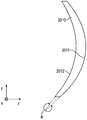
본 발명의 일부 태양에서, 적어도 하나의 방향에서의 광학 굴절력 및 만곡된 제1 주 표면을 포함하는 제1 광학 렌즈, 및 제1 광학 렌즈의 제1 주 표면에 접착된 일체로 형성된 반사 편광기를 포함하는 렌즈 조립체가 제공된다. 일체로 형성된 반사 편광기는 복수의 간섭 층을 포함하며, 각각의 간섭 층은 주로 광학 간섭에 의해 광을 반사시키거나 투과시킨다. 적어도 하나의 간섭 층은 적어도 하나의 위치에서 실질적으로 일축 배향된다. 반사 편광기는 제1 편광 상태를 갖는 광을 실질적으로 투과시키고 직교하는 제2 편광 상태를 갖는 광을 실질적으로 반사시킨다. 제1 주 표면은 최대 투영된 치수(D) 및 대응하는 최대 새그(sag)(S)를 갖는 활성 영역을 포함하며, 여기서 S/D ≥ 0.03이다. 반사 편광기의 평균 두께는 약 50 마이크로미터 초과이다.In some aspects of the invention, a first optical lens comprising an optical refractive power in at least one direction and a curved first major surface, and an integrally formed reflective polarizer adhered to the first major surface of the first optical lens A lens assembly is provided. The integrally formed reflective polarizer comprises a plurality of interfering layers, each interfering layer reflecting or transmitting light mainly by optical interference. The at least one interfering layer is substantially uniaxially oriented in at least one location. The reflective polarizer substantially transmits light having a first polarization state and substantially reflects light having an orthogonal second polarization state. The first major surface comprises an active area with a maximum projected dimension (D) and a corresponding maximum sag (S), where S/D≧0.03. The average thickness of the reflective polarizer is greater than about 50 micrometers.
본 발명의 일부 태양에서, 복수의 간섭 층 및 적어도 하나의 비간섭 층을 포함하는 광학 필름이 제공된다. 각각의 간섭 층은 주로 광학 간섭에 의해 광을 반사시키거나 투과시킨다. 적어도 하나의 비간섭 층은 복수의 간섭 층과 일체로 형성되고, 주로 광학 간섭에 의해 광을 반사시키거나 투과시키지 않는다. 복수의 간섭 층의 평균 총 두께는 약 20 마이크로미터 내지 약 70 마이크로미터이다. 적어도 하나의 비간섭 층의 평균 총 두께는 약 40 마이크로미터 내지 약 100 마이크로미터이다. 미리결정된 파장 범위에서의 실질적 수직 입사광에 대해, 복수의 간섭 층은 제1 편광 상태에 대한 평균 광학 투과율이 약 85% 초과이고 직교하는 제2 편광 상태에 대한 평균 광학 반사율이 약 80% 초과이다.In some aspects of the invention, an optical film is provided that includes a plurality of interfering layers and at least one non-interfering layer. Each interfering layer reflects or transmits light primarily by optical interference. The at least one non-interfering layer is integrally formed with the plurality of interfering layers, and does not reflect or transmit light mainly due to optical interference. The average total thickness of the plurality of interfering layers is from about 20 micrometers to about 70 micrometers. The average total thickness of the at least one non-interfering layer is from about 40 micrometers to about 100 micrometers. For substantially normal incident light in a predetermined wavelength range, the plurality of interfering layers has an average optical transmittance for the first polarization state of greater than about 85% and an average optical reflectance for an orthogonal second polarization state greater than about 80%.
본 발명의 일부 태양에서, 일체로 형성된 반사 편광기 및 반사 편광기의 만곡된 최외부 주 표면 상에 직접 형성되고 그에 정합되는 광학 요소를 포함하는 반사 편광기 조립체가 제공된다.In some aspects of the present invention, a reflective polarizer assembly is provided that includes an integrally formed reflective polarizer and an optical element formed and mated directly on the curved outermost major surface of the reflective polarizer.
일체로 형성된 반사 편광기는 약 50 마이크로미터 초과의 평균 두께를 가지며 복수의 간섭 층을 포함하며, 각각의 간섭 층은 주로 광학 간섭에 의해 광을 반사시키거나 투과시킨다. 적어도 하나의 간섭 층은 적어도 하나의 위치에서 실질적으로 일축 배향된다. 일체로 형성된 반사 편광기는 만곡된 최외부 주 표면을 갖는다.The integrally formed reflective polarizer has an average thickness greater than about 50 micrometers and includes a plurality of interfering layers, each interfering layer reflecting or transmitting light primarily by optical interference. The at least one interfering layer is substantially uniaxially oriented in at least one location. The integrally formed reflective polarizer has a curved outermost major surface.
본 발명의 일부 태양에서, 적어도 하나의 방향에서의 광학 굴절력 및 원치 않는 특징을 갖는 만곡된 제1 주 표면을 갖는 제1 광학 렌즈, 서로 반대편에 있는 최외부 제1 및 제2 주 표면들을 갖는 일체로 형성된 반사 편광기, 및 일체로 형성된 반사 편광기의 제1 주 표면을 제1 광학 렌즈의 제1 주 표면에 접합하는 접착제 층을 포함하는 렌즈 조립체가 제공된다. 일체로 형성된 반사 편광기는 복수의 간섭 층을 포함하며, 각각의 간섭 층은 주로 광학 간섭에 의해 광을 반사시키거나 투과시킨다. 접합은 제1 광학 렌즈의 제1 주 표면의 원치 않는 특징없음을 보상한다. 일체로 형성된 반사 편광기의 최외부 제2 표면은 원하는 특징을 갖는다.In some aspects of the invention, a first optical lens having a curved first major surface with optical power in at least one direction and unwanted features, integral with outermost first and second major surfaces opposite each other A lens assembly is provided comprising a reflective polarizer formed of and an adhesive layer bonding a first major surface of the integrally formed reflective polarizer to a first major surface of a first optical lens. The integrally formed reflective polarizer comprises a plurality of interfering layers, each interfering layer reflecting or transmitting light mainly by optical interference. Bonding compensates for the unwanted features of the first major surface of the first optical lens. The outermost second surface of the integrally formed reflective polarizer has desired characteristics.
본 발명의 일부 태양에서, 적어도 하나의 방향에서의 광학 굴절력이 0 초과인 적어도 하나의 렌즈, 미리결정된 파장 범위에서의 실질적 수직 입사광에 대한 평균 광학 반사율이 30% 이상인 부분 반사기, 및 미리결정된 파장 범위에서의 제1 편광 상태를 갖는 광을 실질적으로 투과시키고 미리결정된 파장 범위에서의 직교하는 제2 편광 상태를 갖는 광을 실질적으로 반사시키는 반사 편광기를 포함하는 광학 시스템이 제공된다. 광학 시스템은 광학 축을 갖는다. 광학 축을 따라 전파하는 광선은 실질적으로 굴절되지 않고서 적어도 하나의 렌즈, 부분 반사기 및 반사 편광기를 통과한다. 제2 편광 상태 및 미리결정된 파장 범위 내의 파장을 가지며 광학 축 상에 중심을 둔 약 100도 내지 약 160도의 전체 원추각을 갖는 광의 입사 원추(incident cone)에 대해, 제1 편광 상태를 갖는 제1 광 성분 및 제2 편광 상태를 갖는 제2 광 성분을 갖는 입사광이 광학 시스템에서 나온다. 제1 광 성분의 평균 세기 대 제2 광 성분의 평균 세기의 비는 약 100 초과이다.In some aspects of the invention, at least one lens having an optical power of refraction greater than 0 in at least one direction, a partial reflector having an average optical reflectivity of at least 30% for substantially normal incident light in a predetermined wavelength range, and a predetermined wavelength range An optical system is provided that includes a reflective polarizer that substantially transmits light having a first polarization state at and substantially reflects light having an orthogonal second polarization state in a predetermined wavelength range. The optical system has an optical axis. The light beam propagating along the optical axis passes through at least one lens, a partial reflector and a reflective polarizer without being substantially refracted. For an incident cone of light having a second polarization state and a wavelength within a predetermined wavelength range and having a total cone angle of about 100 degrees to about 160 degrees centered on the optical axis, a first having a first polarization state The incident light having the light component and the second light component having the second polarization state exits the optical system. The ratio of the average intensity of the first light component to the average intensity of the second light component is greater than about 100.
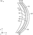
도 1은 광학 컴포넌트의 개략 단면도이다.
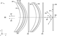
도 2는 광학 시스템의 개략 단면도이다.
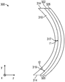
도 3은 광학 컴포넌트의 개략 단면도이다.
도 4 내지 도 6b는 광학 시스템의 개략 단면도이다.
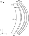
도 7은 광학 컴포넌트의 개략 단면도이다.
도 8 및 도 9는 편광 빔 스플리터의 개략 단면도이다.
도 10은 광학 시스템의 개략 단면도이다.
도 11은 일체로 형성된 반사 편광기의 개략 단면도이다.
도 12 및 도 13은 광학 필름의 개략 단면도이다.
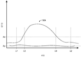
도 14a는 반사 편광기의 층 수의 함수로서의 층 두께의 개략도이다.
도 14b 및 도 14c는 간섭 층의 2개의 패킷을 포함하는 반사 편광기에 대한 층 두께 대 층 수의 플롯이다.
도 15 및 도 16은 렌즈 조립체의 개략 단면도이다.
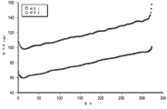
도 17은 반사 편광기의 투과율의 개략 플롯이다.
도 18은 반사 편광기의 반사율의 개략 플롯이다.
도 19는 반사 편광기의 흡수율의 개략 플롯이다.
도 20은 광학 요소의 개략 단면도이다.1 is a schematic cross-sectional view of an optical component.
2 is a schematic cross-sectional view of an optical system.
3 is a schematic cross-sectional view of an optical component.
4 to 6B are schematic cross-sectional views of an optical system.
7 is a schematic cross-sectional view of an optical component.
8 and 9 are schematic cross-sectional views of a polarizing beam splitter.
10 is a schematic cross-sectional view of an optical system.
11 is a schematic cross-sectional view of an integrally formed reflective polarizer.
12 and 13 are schematic sectional views of the optical film.
14A is a schematic diagram of the layer thickness as a function of the number of layers of the reflective polarizer.
14B and 14C are plots of layer thickness versus number of layers for a reflective polarizer comprising two packets of the interfering layer.
15 and 16 are schematic cross-sectional views of a lens assembly.
17 is a schematic plot of transmittance of a reflective polarizer.
18 is a schematic plot of reflectance of a reflective polarizer.
19 is a schematic plot of the absorbance of a reflective polarizer.
20 is a schematic cross-sectional view of an optical element.
하기 설명에서, 본 명세서의 일부를 형성하고 다양한 실시 형태가 예시로서 도시되어 있는 첨부 도면을 참조한다. 도면은 반드시 축척대로 그려진 것은 아니다. 다른 실시 형태가 고려되며 본 발명의 범주 또는 사상으로부터 벗어남이 없이 이루어질 수 있다는 것이 이해되어야 한다. 따라서, 하기의 상세한 설명은 제한적 의미로 해석되어서는 안 된다.In the following description, reference is made to the accompanying drawings, which form a part hereof and show various embodiments as examples. Drawings are not necessarily drawn to scale. It should be understood that other embodiments are contemplated and can be made without departing from the scope or spirit of the invention. Therefore, the following detailed description should not be construed in a limiting sense.
본 발명의 광학 컴포넌트는 반사 편광기 필름, 반사 편광기 조립체, 렌즈 조립체, 및 편광 빔 스플리터(PBS)와 같은 광학 필름을 포함한다. 본 발명의 광학 시스템은 본 발명의 광학 컴포넌트를 포함하는 광학 시스템을 포함한다. 일부 경우에, 광학 시스템은 절첩형 광학계 설계를 이용한다. 본 발명의 일부 실시 형태에 따르면, 광학 스택 내에 반사 편광기를 갖는 비접착성 가요성 광학 층을 포함하고/하거나 두꺼운 다층 광학 필름 반사 편광기를 사용하는 것이, 예를 들어, 반사 편광기가 더 높은 새그 대 직경 비로 만곡되게 할 수 있고, 형성 공정에서 나타나는 결함 없이 적합한 성능을 유지할 수 있다는 것이 밝혀졌다. 예를 들어, 부분 반사기 및 본 발명의 광학 스택 또는 반사 편광기를 포함하는 절첩형 광학계 설계를 이용하는 광학 시스템이, 본 명세서의 어딘가 다른 곳에서 추가로 기술되는 바와 같은 종래의 광학 스택 또는 반사 편광기를 사용하는 것과 비교하여 더 높은 편광 콘트라스트(polarization contrast)를 달성할 수 있다는 것이 밝혀졌다. 다른 예로서, 본 발명의 광학 스택 또는 반사 편광기를 포함하는 편광 빔 스플리터(PBS)를 이용하는 광학 시스템이, 종래의 PBS를 사용하는 광학 시스템과 비교하여 개선된 콘트라스트 및 결함 없이 PBS를 제조하는 개선된 능력을 제공한다는 것이 밝혀졌다.Optical components of the present invention include reflective polarizer films, reflective polarizer assemblies, lens assemblies, and optical films such as polarized beam splitters (PBS). The optical system of the present invention includes an optical system including the optical component of the present invention. In some cases, the optical system uses a foldable optical system design. According to some embodiments of the invention, using a non-adhesive flexible optical layer with a reflective polarizer in the optical stack and/or using a thick multilayer optical film reflective polarizer, for example, It has been found that it can be curved at a ratio of diameters, and can maintain suitable performance without defects that appear in the forming process. For example, an optical system using a collapsible optics design that includes a partial reflector and an optical stack or reflective polarizer of the present invention uses a conventional optical stack or reflective polarizer as further described elsewhere herein. It has been found that it is possible to achieve a higher polarization contrast as compared to that. As another example, an optical system using a polarization beam splitter (PBS) comprising the optical stack or reflective polarizer of the present invention is an improved method of producing PBS without improved contrast and defects compared to an optical system using conventional PBS. It turns out to provide power.
실질적으로 일축 배향되지 않은 반사 편광기 필름(예를 들어, 3M Company(미국 미네소타주 세인트 폴 소재)로부터 입수가능한 듀얼 브라이트니스 인핸스먼트 필름(Dual Brightness Enhancement Film, DBEF))은 총 두께가 100 마이크로미터 초과일 수 있지만, 실질적으로 일축 배향된 필름(예를 들어, 3M Company로부터 입수가능한 어드밴스드 폴라라이징 필름(Advanced Polarizing Films, APF))은 전형적으로 훨씬 더 얇다. 예를 들어, APF 필름은 두께가 전형적으로 약 35 마이크로미터 미만이다. 본 발명에 따르면, 두꺼운(예컨대, 약 50 마이크로미터 초과의 두께의) 실질적으로 일축 배향된 반사 편광기 필름이, 예를 들어 만곡된 형상으로 형성되고 본 명세서의 어딘가 다른 곳에서 추가로 기술되는 바와 같은 광학 시스템에 사용될 때 개선된 특성을 제공한다는 것이 밝혀졌다. 개선된 특성은 개선된 기계적 특성 및 개선된 광학 특성을 포함한다. 개선된 기계적 특성은, 필름 내에 결함(예컨대, 좌굴(buckling)로부터의 주름)을 생성하지 않고서 더 높은 곡률 또는 더 높은 새그 대 직경 비로의 개선된 성형성을 포함한다. 개선된 광학 특성은, 본 명세서의 어딘가 다른 곳에서 추가로 기술되는 바와 같은 절첩형 광학계 설계를 이용하는 광학 시스템에 사용될 때의 개선된 편광 콘트라스트를 포함한다. 일부 경우에, 광학 특성의 개선은, 더 두꺼운 필름 또는 광학 스택이 만곡된 형상으로 형성될 때 반사 편광기 필름의 원하는 광학 특성을 더 양호하게 보존하는 것으로부터 야기된다. 대안적으로, 또는 추가로, 광학 특성의 개선은, 개선된 반사 편광기 필름에서 시작하는 것으로부터 (그를 형성하기 전에) 야기될 수 있다. 예를 들어, 본 명세서의 어딘가 다른 곳에서 추가로 기술되는 바와 같이 일부 간섭 층에 이색성 염료를 포함시키고/시키거나 추가의 간섭 층을 포함함으로써, 감소된 차단 상태 투과율을 갖는 반사 편광기 필름이 제공될 수 있다.Reflective polarizer films that are not substantially uniaxially oriented (e.g., Dual Brightness Enhancement Film (DBEF) available from 3M Company, St. Paul, Minn.) have a total thickness greater than 100 micrometers. Although it may be, substantially uniaxially oriented films (eg, Advanced Polarizing Films (APF) available from 3M Company) are typically much thinner. For example, APF films are typically less than about 35 micrometers thick. According to the present invention, a thick (eg, greater than about 50 micrometer thick) substantially uniaxially oriented reflective polarizer film is formed, for example, in a curved shape and as further described elsewhere herein. It has been found to provide improved properties when used in optical systems. Improved properties include improved mechanical properties and improved optical properties. Improved mechanical properties include improved formability at higher curvature or higher sag to diameter ratio without creating defects (eg, wrinkles from buckling) in the film. The improved optical properties include improved polarization contrast when used in optical systems that utilize a foldable optical system design as further described elsewhere herein. In some cases, the improvement in optical properties results from better preserving the desired optical properties of the reflective polarizer film when a thicker film or optical stack is formed into a curved shape. Alternatively, or additionally, an improvement in optical properties can result from starting (before forming) the improved reflective polarizer film. For example, by including a dichroic dye in some interfering layers and/or including an additional interfering layer as described further elsewhere herein, a reflective polarizer film with reduced blocking transmittance is provided. Can be.
두꺼운 반사 편광기 필름을 사용하는 것에 더하여 또는 그 대신에, 형성 전에 반사 편광기에 비접착성 가요성 광학 필름을 접합하는 것이 물리적 특성을 개선하는 것으로 밝혀졌다. 반사 편광기의 두께는, (예컨대, 동일한 또는 대략 동일한 두께 범위를 갖는 간섭 층의 2개의 패킷을 사용함으로써) 주어진 두께 범위 내의 추가적인 간섭 층을 포함함으로써 그리고/또는 비간섭 층의 두께를 증가시킴으로써 증가될 수 있다.In addition to or instead of using thick reflective polarizer films, bonding non-adhesive flexible optical films to reflective polarizers prior to formation has been found to improve physical properties. The thickness of the reflective polarizer can be increased by including additional interfering layers within a given thickness range (eg, by using two packets of interfering layers having the same or approximately the same thickness range) and/or increasing the thickness of the non-interfering layer. Can be.
일부 실시 형태에서, 반사 편광기는, 높은 콘트라스트를 제공하기 위해 교번하는 중합체 간섭 층의 2개 이상의 패킷을 포함한다. 그러한 반사 편광기는, 2017년 3월 6일자로 출원되고, 이로써, 그것이 본 발명과 상충되지 않을 정도로 본 명세서에 참고로 포함된 미국 가특허 출원 제62/467712호(Haag 등)에 추가로 기재되어 있다. "패킷"이라는 용어는, 패킷 내에 형성된(예컨대, 순차적으로 배열된) 어떠한 스페이서 또는 비간섭 층도 없는 교번하는 간섭 층의 연속 세트를 지칭하는 데 사용된다. 일부 예에서, 스페이서, 비간섭 층, 또는 다른 층이 주어진 스택/패킷의 외부에 추가되어서, 패킷 내의 간섭 층의 교번 패턴을 붕괴시킴이 없이 필름의 외측 층을 형성할 수 있다. 일부 실시 형태에서, 2개의 상이한 패킷 내의 간섭 층의 두께 분포는 반사 편광기의 콘트라스트 비를 증가시키기 위해 실질적으로 중첩된다(예컨대, 양쪽 모두는 동일한 미리결정된 파장 범위를 커버한다). 일부 실시 형태에서, 반사 편광기는 100 이상, 또는 200 이상, 또는 500 이상, 또는 1000 이상, 또는 2000 이상의 콘트라스트 비(통과 편광 상태의 수직 입사광의 투과율을 차단 편광 상태의 수직 입사광의 투과율로 나눈 값)를 갖는다. 이와 비교하여, 종래의 다층 광학 필름 반사 편광기는 종종 약 50 이하의 콘트라스트 비를 갖는다.In some embodiments, the reflective polarizer includes two or more packets of alternating polymer interference layers to provide high contrast. Such a reflective polarizer is filed on March 6, 2017, whereby it is further described in U.S. Provisional Patent Application No. 62/467712 (Haag et al.), incorporated herein by reference to such an extent that it does not conflict with the present invention. have. The term "packet" is used to refer to a continuous set of alternating interfering layers without any spacers or non-interfering layers formed in the packet (eg, arranged sequentially). In some examples, spacers, non-interfering layers, or other layers can be added outside of a given stack/packet to form the outer layer of the film without disrupting the alternating pattern of interfering layers in the packet. In some embodiments, the thickness distribution of the interfering layers in two different packets is substantially overlapped (eg, both cover the same predetermined wavelength range) to increase the contrast ratio of the reflective polarizer. In some embodiments, the reflective polarizer has a contrast ratio of 100 or more, or 200 or more, or 500 or more, or 1000 or more, or 2000 or more (transmittance of normal incident light in a passing polarization state divided by transmittance of vertical incident light in a blocking polarization state) Have In comparison, conventional multilayer optical film reflective polarizers often have a contrast ratio of about 50 or less.
도 1은 만곡된 제1 주 표면(111) 및 반대편 제2 주 표면(112)을 갖는 제1 광학 요소(110); 및 제1 광학 요소(110)의 만곡된 제1 주 표면(111)에 접합되고 정합되는 광학 스택(120)을 포함하는 광학 컴포넌트(100)의 개략 단면도이다. 일부 실시 형태에서, 광학 스택(120)은 선택적인 접착제 층(132)을 통해 광학 요소(110)에 접합된다. 일부 실시 형태에서, 광학 스택(120)은, 광학 요소(110)가 예를 들어 인서트 성형 공정에 의해 광학 스택(120) 상에 일체로 형성됨으로써 광학 요소(110)에 접합되고, 선택적인 접착제 층(132)은 생략된다. 광학 스택(120)은 제1 및 제2 층들(122, 126)을 포함한다. 제1 층(122)은 서로 반대편에 있는 제1 및 제2 주 표면들(123, 124)을 가지며, 제2 층(126)은 서로 반대편에 있는 제1 및 제2 주 표면들(127, 128)을 갖는다. 일부 실시 형태에서, 제1 및 제2 층들(122, 126)은 선택적인 접착제 층(130)을 통해 서로 접합된다. 일부 실시 형태에서, 제1 및 제2 층들(122, 126)은 서로 일체로 형성됨으로써 서로 접합되고, 선택적인 접착제 층(130)은 생략된다.1 shows a first
본 명세서에 사용되는 바와 같이, 제2 요소와 "일체로 형성된" 제1 요소란, 제1 및 제2 요소들이 별도로 제조된 후에 후속하여 결합되기보다는 오히려 함께 제조되는 것을 의미한다. 일체로 형성되는 것은, 제1 요소를 제조하는 것, 이어서 제1 요소 상에 제2 요소를 제조하는 것을 포함한다. 복수의 층을 포함하는 반사 편광기는, 층들이 별도로 제조된 후 후속하여 결합되기보다는 오히려 함께 제조되는 (예컨대, 용융물 스트림으로서 조합되고 이어서 냉각 롤 상으로 캐스팅되어 층들 각각을 갖는 캐스트 필름을 형성하고, 이어서 캐스트 필름을 배향하는) 경우 일체로 형성된다.As used herein, a first element that is “one-piece” with a second element means that the first and second elements are manufactured separately, and then joined together rather than subsequently joined. Integrally formed includes manufacturing a first element, followed by manufacturing a second element on the first element. A reflective polarizer comprising a plurality of layers is formed separately (e.g., as a melt stream and then cast onto a cooling roll) to form a cast film having each of the layers, rather than being separately produced and subsequently joined together, then cast onto a cooling roll, If the cast film is then oriented) it is formed integrally.
본 명세서에 사용되는 임의의 접착제 층은 평균 두께가 약 1 마이크로미터 내지 약 50 마이크로미터일 수 있다. 접착제 층은, 예를 들어 감압 접착제, 핫 멜트 접착제, 열경화성 접착제, 용매계 접착제, 및 수계 접착제 중 하나 이상일 수 있거나 이를 포함할 수 있다. 일부 실시 형태에서, 접착제 층은, 본 명세서의 어딘가 다른 곳에 추가로 기재된 바와 같이 바로 인접한 층에 실질적으로 굴절률 매칭된다. 일부 실시 형태에서, 접착제 층은 광학적으로 투명한 접착제 층이다. 적합한 광학적으로 투명한 접착제에는, 예를 들어 3M Company로부터 입수가능한 것들(예컨대, 각각 1 밀(mil) 및 2 밀의 두께인 3M 옵티컬리 클리어 어드히시브(3M Optically Clear Adhesive) 8171 및 8172) 및 Norland Products Inc.(미국 뉴저지주 크랜버리 소재)로부터 입수가능한 놀랜드 옵티컬 어드히시브즈(Norland Optical Adhesives)가 포함된다.Any adhesive layer used herein can have an average thickness from about 1 micrometer to about 50 micrometers. The adhesive layer can be or include, for example, one or more of pressure sensitive adhesives, hot melt adhesives, thermosetting adhesives, solvent-based adhesives, and water-based adhesives. In some embodiments, the adhesive layer is substantially refractive index matched to the immediately adjacent layer, as further described elsewhere herein. In some embodiments, the adhesive layer is an optically transparent adhesive layer. Suitable optically clear adhesives include, for example, those available from 3M Company (e.g., 3M Optically Clear Adhesive 8171 and 8172, 1 mil and 2 mil thick, respectively) and Norland Products Norland Optical Adhesives, available from Inc. (Cranbury, NJ).
일부 실시 형태에서, 제1 층(122)은 제1 편광 상태를 갖는 광을 실질적으로 투과시키고 직교하는 제2 편광 상태를 갖는 광을 실질적으로 반사시키는 반사 편광기이고; 제2 층(126)은, 반사 편광기에 접합되고, 실질적으로 평행한 서로 반대편에 있는 제1 및 제2 주 표면들(127, 128)을 갖는 비접착성 가요성 광학 층이다. 일부 실시 형태에서, 제2 층(126)은 제1 편광 상태를 갖는 광을 실질적으로 투과시키고 직교하는 제2 편광 상태를 갖는 광을 실질적으로 반사시키는 반사 편광기이고; 제1 층(122)은, 반사 편광기에 접합되고, 실질적으로 평행한 서로 반대편에 있는 제1 및 제2 주 표면들(123, 124)을 갖는 비접착성 가요성 광학 층이다.In some embodiments,
일부 실시 형태에서, 제2 층(126)은 제1 층(122)에 이형가능하게 접합된 라이너이다. 광학 필름을 보호하기 위해 광학 필름을 만곡된 형상으로 형성하기 전에 이형 라이너가 광학 필름에 적용될 수 있다. 이형 라이너들 중 하나는 광학 필름 상에 렌즈 또는 다른 광학 요소를 성형하기 전에 제거될 수 있고, 다른 이형 라이너는 광학 필름을 보호하기 위해(예컨대, 몰드가, 몰드로부터 광학 필름 상으로 표면 텍스처를 부여하거나 긁지 않도록) 유지될 수 있다. 광학 필름에 접합되어 있지만 광학 필름을 실질적으로 손상시키지 않고서 광학 필름으로부터 깨끗하게 제거될 수 있는 라이너는 광학 필름에 이형가능하게 접합되는 것으로 기술될 수 있고 이형 라이너로서 기술될 수 있다. 일부 실시 형태에서, 광학 필름에 이형가능하게 접합되는 라이너는 광학 필름에 대한 가시적인 손상 없이 광학 필름으로부터 제거될 수 있다. 이형가능하게 접합된 라이너는, 기재에 강하게 접합되지만 광학 필름에는 약하게 접합되는 접착제 층을 갖는 기재를 포함할 수 있다. 예를 들어, 라이너는, 접착제에 대한 그의 접합을 증가시키도록 처리된 표면을 갖는 기재에 적용되는 낮은 점착성 접착제의 얇은 층을 포함할 수 있다. 다른 적합한 라이너에는, 예를 들어 미국 특허 제6,991,695호(Tait 등)에 기재된 바와 같이 광학 필름에 정전기적으로 접합되는 것들이 포함된다. 적합한 라이너의 일례는 Sun A Kaken Co, Ltd.로부터 입수가능한 OCPET NSA33T이다.In some embodiments, the
비접착성 가요성 광학 층의 제1 및 제2 주 표면들은, 비접착성 가요성 광학 층이 무시해도 될 정도의 광학 굴절력을 갖도록 주 표면들이 평행에 충분히 가까운 경우 또는 제1 및 제2 주 표면들의 80% 이상에 걸친 각각의 쌍의 대향 지점들에서의 기울기들이 30도 이하만큼 상이한 경우 실질적으로 평행한 것으로 기술될 수 있다. 일부 실시 형태에서, 제1 및 제2 주 표면들의 80% 이상, 또는 85% 이상, 또는 90% 이상에 걸친 각각의 쌍의 대향 지점들의 기울기들은 20도 이하, 또는 10도 이하, 또는 5도 이하만큼 상이하다. 대향 지점들은, 비접착성 가요성 광학 층의 두께 방향을 따른 선을 따른 지점들을 지칭하며, 여기서 선은 제1 및 제2 주 표면들 중 적어도 하나에 수직이다. 일부 실시 형태에서, 비접착성 가요성 광학 층은, 원하는 형상으로 형성되기 전에 평행한 주 표면을 가졌지만, 형성으로부터 야기되는 층의 두께 변화로 인해 형성 후에는 정확하게 평행하지 않을 수 있는 표면을 가졌다.The first and second major surfaces of the non-adhesive flexible optical layer, if the major surfaces are sufficiently close to parallel or the first and second major surfaces so that the non-adhesive flexible optical layer has negligible optical refractive power. It can be described as being substantially parallel if the inclinations at the opposing points of each pair over 80% or more of are different by 30 degrees or less. In some embodiments, the slopes of the opposing points of each pair spanning 80% or more, or 85% or more, or 90% or more of the first and second major surfaces are 20 degrees or less, or 10 degrees or less, or 5 degrees or less As different as Opposing points refer to points along a line along the thickness direction of the non-adhesive flexible optical layer, where the line is perpendicular to at least one of the first and second major surfaces. In some embodiments, the non-adhesive flexible optical layer had a major surface that was parallel before being formed into a desired shape, but a surface that could not be exactly parallel after formation due to a change in the thickness of the layer resulting from the formation. .
반사 편광기는 미리결정된 파장 범위에서, 직교하는 제1 및 제2 편광 상태들 중 하나(예컨대, x-축을 따른 전기장을 갖는 제1 편광 상태)를 갖는 광을 실질적으로 반사시키고, 제1 및 제2 편광 상태들 중 다른 하나(예컨대, y-축을 따른 전기장을 갖는 제2 편광 상태)를 갖는 광을 실질적으로 투과시킨다. 반사 편광기는, 반사 편광기의 일 면으로부터 반사 편광기 상에 수직으로 입사되고 미리결정된 파장 범위에서의 제1 편광 상태를 갖는 광의 60% 이상이 반사 편광기를 통해 투과되는 경우 미리결정된 파장 범위에서의 제1 편광 상태를 갖는 광을 실질적으로 투과시키는 것으로 칭해질 수 있다. 일부 실시 형태에서, 미리결정된 파장 범위에서의 제1 편광 상태를 갖는 광의 70% 이상, 또는 80% 이상, 또는 85% 이상이 편광기를 통해 투과된다. 반사 편광기는, 반사 편광기의 일 면으로부터 반사 편광기 상에 수직으로 입사되고 미리결정된 파장에서의 제2 편광 상태를 갖는 광의 60% 이상이 반사 편광기로부터 반사되는 경우 미리결정된 파장 범위에서의 제2 편광 상태를 갖는 광을 실질적으로 반사시키는 것으로 칭해질 수 있다. 일부 실시 형태에서, 미리결정된 파장 및 제2 편광 상태를 갖는 광의 70% 이상, 또는 80% 이상, 또는 85% 이상이 편광기로부터 반사된다. 일부 실시 형태에서, 본 명세서의 어딘가 다른 곳에서 추가로 기술되는 바와 같이, 반사 편광기는 제2 편광 상태를 갖는 광을 부분적으로 흡수하는 층을 포함할 수 있다.The reflective polarizer substantially reflects light having one of orthogonal first and second polarization states (eg, a first polarization state having an electric field along the x-axis) at a predetermined wavelength range, and the first and second Light having another of the polarization states (eg, a second polarization state with an electric field along the y-axis) is substantially transmitted. The reflective polarizer is first in the predetermined wavelength range when at least 60% of light having a first polarization state in a predetermined wavelength range and incident on the reflective polarizer from one side of the reflective polarizer is transmitted through the reflective polarizer. It can be said to substantially transmit light having a polarization state. In some embodiments, 70% or more, or 80% or more, or 85% or more of light having a first polarization state in a predetermined wavelength range is transmitted through the polarizer. The reflective polarizer is a second polarization state in a predetermined wavelength range when 60% or more of light having a second polarization state at a predetermined wavelength and incident on the reflective polarizer from one side of the reflective polarizer is reflected from the reflective polarizer. It may be referred to as substantially reflecting light having a. In some embodiments, 70% or more, or 80% or more, or 85% or more of light having a predetermined wavelength and a second polarization state is reflected from the polarizer. In some embodiments, the reflective polarizer may include a layer that partially absorbs light having a second polarization state, as further described elsewhere herein.
미리결정된 파장 범위는, 광학 시스템이 동작하도록 설계되는 파장 범위일 수 있다. 예를 들어, 미리결정된 파장 범위는 가시 범위(400 nm 내지 700 nm)일 수 있다. 다른 예로서, 미리결정된 파장 범위는 하나 이상의 가시 파장 범위를 포함할 수 있다. 예를 들어, 미리결정된 파장 범위는 하나 초과의 좁은 파장 범위의 조합(예컨대, 디스플레이 패널의 발광 색상에 대응하는 분리된 적색, 녹색 및 청색 파장 범위의 조합)일 수 있다. 그러한 파장 범위는 미국 특허 출원 공개 제2017/0068100호(Ouderkirk 등)에 추가로 기재되어 있으며, 이는 이로써 본 발명과 상충되지 않을 정도로 본 명세서에 참고로 포함된다. 일부 실시 형태에서, 미리결정된 파장 범위는, 가시 파장 범위뿐만 아니라 다른 파장 범위(예컨대, 적외선(예컨대, 근적외선(약 700 nm 내지 약 2500 nm)), 또는 자외선(예컨대, 근자외선(약 300 nm 내지 약 400 nm)))를 포함한다.The predetermined wavelength range may be a wavelength range in which the optical system is designed to operate. For example, the predetermined wavelength range may be a visible range (400 nm to 700 nm). As another example, the predetermined wavelength range can include one or more visible wavelength ranges. For example, the predetermined wavelength range may be a combination of more than one narrow wavelength range (eg, a combination of separate red, green and blue wavelength ranges corresponding to the emission color of the display panel). Such wavelength ranges are further described in US Patent Application Publication No. 2017/0068100 (Ouderkirk et al.), which is hereby incorporated by reference to the extent that it does not conflict with the present invention. In some embodiments, the predetermined wavelength range is not only the visible wavelength range, but also other wavelength ranges (eg, infrared (eg, near infrared (about 700 nm to about 2500 nm)), or ultraviolet (eg, near ultraviolet (about 300 nm to) About 400 nm))).
본 발명의 광학 시스템에 사용되는 반사 편광기는 임의의 적합한 유형의 반사 편광기일 수 있다. 반사 편광기는, 예를 들어 미국 특허 제5,882,774호(Jonza 등), 및 미국 특허 제6,609,795호(Weber 등)에 기재된 것들과 같은 중합체 다층 광학 필름일 수 있다. 반사 편광기는 실질적으로 일축 배향될 수 있다. 반사 편광기 또는 반사 편광기 내의 층은, 그것이 하나의 면내 방향으로 실질적으로 배향되고, 직교하는 면내 방향으로 실질적으로 배향되지 않고 두께 방향으로 실질적으로 배향되지 않는 경우 실질적으로 일축 배향된다. 실질적으로 일축 배향된 반사 편광기는 3M Company로부터 상표명 어드밴스드 폴라라이징 필름 또는 APF로 입수가능하다. 다른 유형의 다층 광학 필름 반사 편광기(예컨대, 3M Company로부터 입수가능한 듀얼 브라이트니스 인핸스먼트 필름 또는 DBEF)가 또한 사용될 수 있다. DBEF 필름은 직교하는 면내 방향에서보다 하나의 면내 방향으로 실질적으로 더 많이 배향되고, 또한 두께 방향으로의 배향을 나타낸다. DBEF 필름은, "실질적으로 일축 배향된 것"이 본 명세서에서 사용된 바와 같이 실질적으로 일축 배향되어 있지는 않다.The reflective polarizer used in the optical system of the present invention can be any suitable type of reflective polarizer. The reflective polarizer can be, for example, a polymer multilayer optical film such as those described in US Pat. No. 5,882,774 (Jonza et al.), and US Pat. No. 6,609,795 (Weber et al.). The reflective polarizer can be substantially uniaxially oriented. The reflective polarizer or the layer within the reflective polarizer is substantially uniaxially oriented if it is substantially oriented in one in-plane direction and not substantially oriented in the orthogonal in-plane direction and not substantially oriented in the thickness direction. A substantially uniaxially oriented reflective polarizer is available from 3M Company under the trade name Advanced Polarizing Film or APF. Other types of multilayer optical film reflective polarizers (eg dual brightness enhancement films or DBEFs available from 3M Company) can also be used. The DBEF film is oriented substantially more in one in-plane direction than in the orthogonal in-plane direction, and also exhibits orientation in the thickness direction. The DBEF film is not substantially "uniaxially oriented" as used herein, as used herein.
일부 실시 형태에서, 만곡된 형상으로 형성하기 전의 반사 편광기는, 그것이 0.7 이상, 또는 0.8 이상, 또는 0.85 이상의 일축 특성의 정도(U)를 갖는다는 점에서 실질적으로 일축 배향되고, 여기서 U = (1/MDDR - 1) / (TDDR1/2 - 1)이며, 이때 MDDR은 기계 방향 연신비(machine direction draw ratio)로서 정의되고, TDDR은 횡방향 연신비(transverse direction draw ratio)로서 정의된다. 그러한 실질적으로 일축 배향된 다층 광학 필름은, 이로써, 본 발명과 상충되지 않을 정도로 본 명세서에 참고로 포함되는 미국 특허 출원 공개 제2010/0254002호(Merrill 등)에 기재되어 있고, 복수의 교번하는 제1 및 제2 중합체 층들을 포함할 수 있으며, 이때 제1 중합체 층은 굴절률이 길이 방향(예컨대, x-방향) 및 두께 방향(예컨대, z-방향)에서는 실질적으로 동일하지만 폭 방향(예컨대, y-방향)에서는 실질적으로 상이하다. 예를 들어, x-방향 및 z-방향에서의 굴절률들의 차이의 절대값은 0.02 미만 또는 0.01 미만일 수 있고, x-방향 및 y-방향에서의 굴절률들의 차이의 절대값은 0.05 초과 또는 0.10 초과일 수 있다. 달리 명시된 경우를 제외하고는, 굴절률은 550 nm의 파장에서의 굴절률을 지칭한다. 만곡된 형상으로 형성한 후에, 반사 편광기는 적어도 하나의 위치에서 실질적으로 일축 배향되는 적어도 하나의 층을 가질 수 있다. 일부 실시 형태에서, 적어도 하나의 위치에서의 적어도 하나의 층은, 그 층의 두께를 따른 제1 방향에서의 제1 굴절률, 제1 방향에 직교하는 제2 방향에서의 제2 굴절률, 및 제1 및 제2 방향들에 직교하는 제3 방향에서의 제3 굴절률을 가지며, 제1 굴절률과 제3 굴절률의 차이의 절대값은 약 0.02 미만, 또는 약 0.01 미만이고, 제2 굴절률과 제3 굴절률의 차이의 절대값은 약 0.05 초과, 또는 약 0.10 초과이다. 일부 실시 형태에서, 만곡된 형상으로 형성된 후에, 반사 편광기는 복수의 위치에서 실질적으로 일축 배향되는 적어도 하나의 층을 갖는다.In some embodiments, the reflective polarizer before forming into a curved shape is substantially uniaxially oriented in that it has a degree of uniaxial property U of at least 0.7, or at least 0.8, or at least 0.85, where U = (1 / MDDR - 1) / (
본 발명에 따르면, 종래의 실질적으로 일축 배향된 반사 편광기 필름보다 실질적으로 더 두꺼운 실질적으로 일축 배향된 반사 편광기 필름이, 만곡된 형상으로 형성되고 본 명세서의 어딘가 다른 곳에서 추가로 기술되는 바와 같은 광학 시스템에 사용될 때 개선된 특성을 제공한다는 것이 밝혀졌다. 일부 실시 형태에서, 반사 편광기의 평균 두께는 약 50 마이크로미터 초과, 또는 약 60 마이크로미터 초과, 또는 약 70 마이크로미터 초과이다.According to the present invention, a substantially uniaxially oriented reflective polarizer film that is substantially thicker than a conventional substantially uniaxially oriented reflective polarizer film is formed into a curved shape and is optically described elsewhere elsewhere herein. It has been found to provide improved properties when used in systems. In some embodiments, the average thickness of the reflective polarizer is greater than about 50 micrometers, or greater than about 60 micrometers, or greater than about 70 micrometers.
반사 편광기 또는 미러 필름 내의 더 높은 굴절률의 간섭 층에 적합한 재료에는, 예를 들어 폴리에틸렌 나프탈레이트(PEN), PEN 및 폴리에스테르를 함유하는 공중합체(예컨대, 폴리에틸렌 테레프탈레이트(PET) 또는 다이벤조산), 글리콜 개질된 폴리에틸렌 테레프탈레이트가 포함된다. 반사 편광기 또는 미러 필름 내의 더 낮은 굴절률의 간섭 층에 적합한 재료에는, 예를 들어 PEN에 기초한 코폴리에스테르, PET에 기초한 코폴리에스테르, 폴리카르보네이트(PC), 또는 이들 3가지 부류의 재료들의 블렌드가 포함된다. 원하는 수의 층들로 높은 반사율을 달성하기 위해, 인접한 미세층들은 차단 축을 따라 편광된 광에 대한 굴절률들의 차이가 예를 들어, 0.2 이상인 것을 나타낼 수 있다.Materials suitable for higher refractive index interfering layers in reflective polarizers or mirror films include, for example, polyethylene naphthalate (PEN), copolymers containing PEN and polyesters (e.g. polyethylene terephthalate (PET) or dibenzoic acid), Glycol modified polyethylene terephthalate. Materials suitable for lower refractive index interfering layers in reflective polarizers or mirror films include, for example, copolyesters based on PEN, copolyesters based on PET, polycarbonates (PC), or these three classes of materials. Blends are included. To achieve high reflectivity with a desired number of layers, adjacent microlayers may indicate that the difference in refractive indices for light polarized along the blocking axis is, for example, 0.2 or more.
비접착성 가요성 광학 층은, 인접한 층들을 함께 접합하고 가요성인 접착제가 아닌 광학 층이다. 일부 경우에, D = (1/12) Et3/(1-μ2)에 의해 주어지는 층의 굴곡 강성의 관점에서 층의 가요성을 특성화하는 것이 편리한데, 여기서 t는 층 두께이고, E는 영률(Young's modulus)이고, μ는 푸아송비(Poisson ratio)이다. 일부 실시 형태에서, 비접착성 가요성 광학 층은 굴곡 강성이 100 N-m 미만, 또는 50 N-m 미만, 또는 20 N-m 미만, 또는 10 N-m 미만, 또는 5 N-m 미만, 또는 3 N-m 미만, 또는 1 N-m 미만, 또는 0.5 N-m 미만이다.The non-adhesive flexible optical layer is an optical layer that bonds adjacent layers together and is not a flexible adhesive. In some cases, it is convenient to characterize the flexibility of a layer in terms of the flexural stiffness of the layer given by D = (1/12) Et 3 /(1-μ 2 ), where t is the layer thickness and E is Young's modulus, μ is the Poisson ratio. In some embodiments, the non-adhesive flexible optical layer has a flexural stiffness of less than 100 Nm, or less than 50 Nm, or less than 20 Nm, or less than 10 Nm, or less than 5 Nm, or less than 3 Nm, or less than 1 Nm, Or less than 0.5 Nm.
비접착성 가요성 광학 층은, 예를 들어 중합체 필름, 반사 방지 코팅, 흡수 편광기, 중성 밀도 필터, 지연기, 염색된 필름, 광학 필터, 전기 회로를 포함하는 필름, 전극, 적외선 반사 필름, 다층 광학 필름, 및 확산기 중 하나 이상일 수 있거나 이를 포함할 수 있다. 일부 실시 형태에서, 비접착성 가요성 광학 층은 광학적으로 투명한 필름 기재, 예컨대 폴리에틸렌 테레프탈레이트(PET), 폴리에틸렌 나프탈레이트(PEN), 또는 폴리메틸메타크릴레이트(PMMA)이다. 필름 또는 접착제 층은, 그것이 미리결정된 파장 범위(예컨대, 400 nm 내지 700 nm)에서의 비편광된 수직 입사광의 투과율이 80% 이상이고 탁도가 20% 미만인 경우 광학적으로 투명한 것으로 기술될 수 있다. 일부 실시 형태에서, 비접착성 가요성 광학 층은, 400 nm 내지 700 nm의 파장 범위에서의 비편광된 수직 입사광의 투과율이 85% 이상이고 탁도가 10% 미만, 또는 5% 미만인 광학적으로 투명한 필름이다. 일부 실시 형태에서, 비접착성 가요성 광학 층은 염색된 필름 및/또는 광학 필터이고, 투과된 광의 일부 태양(예컨대, 색상 또는 세기)을 조정하는 데 사용된다. 예를 들어, 필터를 통해 투과되는 모든 가시광의 세기를 감소시키기 위해 중성 밀도 필터가 포함될 수 있다. 예를 들어, 전기 회로가 디스플레이 요소 또는 터치 감응형 요소를 제어하는 데 사용될 수 있다. 예를 들어, 액정 디스플레이 요소를 어둡게 하기 위해 전극이 포함될 수 있다. 일부 실시 형태에서, 비접착성 가요성 광학 층은 본 명세서의 어딘가 다른 곳에 추가로 기재된 바와 같은 이형 라이너이다. 일부 실시 형태에서, 이형 라이너는, 예를 들어 PET 기재를 포함한다.Non-adhesive flexible optical layers include, for example, polymer films, anti-reflective coatings, absorbing polarizers, neutral density filters, retarders, dyed films, optical filters, films comprising electrical circuits, electrodes, infrared reflective films, multilayers One or more of an optical film, and a diffuser. In some embodiments, the non-adhesive flexible optical layer is an optically transparent film substrate, such as polyethylene terephthalate (PET), polyethylene naphthalate (PEN), or polymethylmethacrylate (PMMA). The film or adhesive layer can be described as optically transparent when it has a transmittance of 80% or more and less than 20% turbidity of unpolarized vertical incident light in a predetermined wavelength range (eg, 400 nm to 700 nm). In some embodiments, the non-adhesive flexible optical layer is an optically transparent film having a transmittance of at least 85% and a haze of less than 10%, or less than 5% of unpolarized vertical incident light in a wavelength range of 400 nm to 700 nm. to be. In some embodiments, the non-adhesive flexible optical layer is a dyed film and/or optical filter and is used to adjust some aspect (eg, color or intensity) of transmitted light. For example, a neutral density filter may be included to reduce the intensity of all visible light transmitted through the filter. For example, electrical circuits can be used to control display elements or touch-sensitive elements. For example, electrodes may be included to darken the liquid crystal display element. In some embodiments, the non-adhesive flexible optical layer is a release liner as further described elsewhere herein. In some embodiments, the release liner includes, for example, a PET substrate.
일부 실시 형태에서, 제1 광학 요소(110)는 강성이다. 예를 들어, 제1 광학 요소(110)는, 제1 광학 요소(110)가 0.5 lb(2.2 뉴턴(Newton)) 힘의 인가 하에서 인지가능하게 휘어지지 않는 충분한 두께로 유리 재료 또는 중합체 재료로 제조될 수 있다. 일부 실시 형태에서, 제1 광학 요소(110)는 비접착성 가요성 광학 층(제1 층(122) 및 제2 층(126) 중 하나)보다 덜 가요성이다. 예를 들어, 제1 광학 요소(110)는 강성일 수 있는 반면, 비접착성 가요성 광학 층은 가요성 필름(예컨대, 0.5 lb 힘의 인가 하에서 인지가능하게 휘어지거나 접히는 필름)일 수 있다.In some embodiments, first
광학 컴포넌트(100)는 광학 시스템 내의 컴포넌트로서 사용될 수 있거나, 또는 광학 시스템 그 자체인 것으로 간주될 수 있다. 일부 실시 형태에서, 광학 요소(110)는 광학 렌즈이고, 광학 컴포넌트(100)는 렌즈 조립체이다. 일부 실시 형태에서, 광학 렌즈는 적어도 하나의 방향에서의 광학 굴절력을 갖는다. 예를 들어, 광학 렌즈는, 도 1의 x-y-z 좌표계를 참조하여, y-방향에서의 광학 굴절력을 갖는 원통형 렌즈일 수 있다. 다른 예로서, 광학 렌즈는 2개의 상호 직교하는 방향(예컨대, x-방향 및 y-방향)으로 만곡될 수 있고, 2개의 상호 직교하는 방향(예컨대, x-방향 및 y-방향)에서의 광학 굴절력을 가질 수 있다. 일부 실시 형태에서, 광학 렌즈는 실질적으로 평면인 표면을 갖는다(예컨대, 제2 주 표면(112)은 평면형일 수 있다). 표면의 80% 이상에 걸친 각각의 지점이 표면의 최대 측방향 치수의 5배 이상인 곡률 반경을 갖는 경우, 그 표면은 실질적으로 평면형이다. 일부 실시 형태에서, 실질적으로 평면인 표면은, 곡면의 80% 이상, 또는 90% 이상, 또는 95% 이상에 걸친 각각의 지점에서의 곡률 반경이, 표면의 최대 측방향 치수의 5배 이상, 또는 10배 이상, 또는 20배 이상, 또는 50배 이상이다.The
도 2는 렌즈 조립체(200)를 포함하는 광학 시스템(201)의 개략 단면도이다. 렌즈 조립체(200)는 광학 컴포넌트(100)에 대응할 수 있고, 제1 렌즈(210), 및 제1 렌즈(210)의 만곡된 주 표면 상에 배치되고 그에 정합되는 광학 스택(220)을 포함한다. 광학 스택(220)은 제1 층(222) 및 제2 층(226)을 포함한다. 선택적인 접착제 층이 제1 층(222)과 제2 층(226) 사이에 그리고/또는 광학 스택(220)과 제1 렌즈(210) 사이에 배치될 수 있다. 일부 실시 형태에서, 제1 및 제2 층들(222, 226) 중 하나는 반사 편광기이고, 제1 및 제2 층들(222, 226) 중 다른 하나는 비접착성 가요성 광학 층이다. 광학 시스템(201)은 지연기(235), 지연기(239), 및 제2 렌즈(240)를 추가로 포함하며, 제2 렌즈는 제2 렌즈(240)의 주 표면 상에 배치된 부분 반사기(242)를 갖는다. 일부 실시 형태에서, 광학 시스템(201)은 디스플레이(250)에 의해 방출된 이미지를 관찰 위치(265)에 디스플레이하도록 구성된다.2 is a schematic cross-sectional view of an
일부 실시 형태에서, 제1 렌즈(210) 및 제1 광학 스택(220)은 제2 렌즈(240)로부터 이격되어 있다. 일부 실시 형태에서, 제1 렌즈(210)는 실질적으로 비평행한 제1 및 제2 주 표면들을 갖는 제1 광학 요소이고, 제2 렌즈(240)는 실질적으로 비평행한 제1 및 제2 주 표면들을 갖는 제2 광학 요소이다. 렌즈의 제1 및 제2 주 표면들은, 렌즈가 무시할 수 없는 광학 굴절력을 갖도록 주 표면들이 충분히 상이한 경우 또는 제1 및 제2 주 표면들 상의 적어도 한 쌍의 대향 지점들에서의 기울기들이 10도 이상만큼 상이한 경우 실질적으로 비평행한 것으로 기술될 수 있다. 일부 실시 형태에서, 제1 및 제2 주 표면들 상의 적어도 한 쌍의 대향 지점들에서의 기울기들은 20도 이상 또는 30도 이상만큼 상이하다. 대향 지점들은, 렌즈의 두께 방향을 따른 선을 따른 지점들을 지칭하며, 여기서 선은 제1 및 제2 주 표면들 중 하나에 수직이다. 프리즘의 제1 및 제2 주 표면들은, 표면들 사이의 각도가 약 20도 이상인 경우에 실질적으로 비평행한 것으로 기술될 수 있다. 일부 실시 형태에서, 프리즘의 실질적으로 비평행한 제1 주 표면과 제2 주 표면 사이의 각도는 약 30도 이상이다.In some embodiments,
광학 시스템(201)의 다른 구성이 가능하다. 일부 실시 형태에서, 지연기(235)는 제1 렌즈(210)의 반대편에 있는 광학 스택(220) 상에 배치될 수 있거나, 또는 부분 반사기(242)의 반대편에 있는 제2 렌즈(240) 상에 배치될 수 있다. 일부 실시 형태에서, 지연기(239)는 부분 반사기(242) 상에 배치될 수 있거나, 또는 디스플레이(250) 상에 배치될 수 있다. 일부 실시 형태에서, 제1 및 제2 렌즈들(210, 240)은 (예컨대, 하나의 주 표면 상의 부분 반사기(242) 및 반대편 주 표면 상의 광학 스택(220)을 갖는) 단일 렌즈로 대체된다. 또 다른 실시 형태에서, 2개 초과의 렌즈가 포함된다. 광학 시스템을 위한 다른 가능한 배열은 미국 특허 출원 공개 제2017/0068100호(Ouderkirk 등)에 기재되어 있다. 광학 스택(220)은, 미국 특허 출원 공개 제2017/0068100호(Ouderkirk 등)에 기재된 임의의 실시 형태에서의 반사 편광기 대신에 사용될 수 있다.Other configurations of
일부 실시 형태에서, 디스플레이(250)는 반사 편광기의 차단 편광 상태의 광을 방출하고, 지연기(235, 239)는 디스플레이에 의해 방출된 광이 먼저 차단 편광 상태에서 반사 편광기 상에 입사되도록 배치된다. 예를 들어, 지연기(235, 239)는 서로에 대해 약 90도로 배향된 진상축(fast axis)을 가질 수 있다. 지연기(235, 239)는 각각 미리결정된 파장 범위 내의 적어도 하나의 파장에서의 1/4 파장 지연기일 수 있다. 다른 구성이 또한 가능하다. 예를 들어, 지연기(235, 239)는 그들 각각의 진상축이 정렬된 1/4 파장 지연기일 수 있다. 이 경우에, 디스플레이(250)는 반사 편광기의 통과 편광 상태의 광을 방출할 수 있어, 광이 먼저 차단 상태에서 반사 편광기 상에 입사되도록 한다.In some embodiments, the
지연기(235 및/또는 239)는 기재 또는 렌즈 상의 코팅일 수 있거나, 또는 지연기 필름일 수 있고, 예를 들어, 미국 특허 출원 공개 US 2002/0180916호(Schadt 등), US 2003/028048호(Cherkaoui 등) 및 US 2005/0072959호(Moia 등)에 기재된 선형 광중합성 중합체(LPP) 재료 및 액정 중합체(LCP) 재료를 포함하는 임의의 적합한 재료로 형성될 수 있다. 적합한 LPP 재료는 ROP-131 EXP 306 LPP를 포함하고, 적합한 LCP 재료는 ROF-5185 EXP 410 LCP를 포함하며, 이들 둘 모두는 스위스 알슈빌 소재의 Rolic Technologies로부터 입수가능하다. 일부 실시 형태에서, 지연기(235)는 미리결정된 파장 범위(예컨대, 400 nm 내지 700 nm) 내의 적어도 하나의 파장에서의 1/4 파장 지연기이다.The
부분 반사기(242)는 임의의 적합한 부분 반사기일 수 있고, 예를 들어 미리결정된 파장 범위에서의 평균 광학 반사율이 20% 이상 또는 30% 이상일 수 있다. 예를 들어, 부분 반사기는 투명한 기재(예컨대, 렌즈에 이어서 접착될 수 있는 필름, 또는 기재는 렌즈일 수 있음) 상에 금속(예컨대, 은 또는 알루미늄)의 얇은 층을 코팅함으로써 구성될 수 있다. 부분 반사기는 또한, 예를 들어, 렌즈 기재의 표면 상으로 박막 유전체 코팅을 침착시킴으로써, 또는 표면 상에 금속 코팅과 유전체 코팅의 조합을 침착시킴으로써 형성될 수 있다. 일부 실시 형태에서, 부분 반사기는, 미리결정된 파장 또는 미리결정된 파장 범위에서의 평균 광학 반사율 및 평균 광학 투과율이 각각 20% 내지 80%의 범위에 있거나, 또는 각각 30% 내지 70%의 범위에 있거나, 또는 각각 40% 내지 60%의 범위에 있거나, 또는 각각 45% 내지 55%의 범위에 있다. 부분 반사기는, 예를 들어 하프 미러(half mirror)일 수 있다. 미리결정된 파장 범위에서의 평균 광학 반사율 및 평균 광학 투과율은, 각각, 달리 지시되지 않는 한, 수직 입사 시 결정되는, 미리결정된 파장 범위에 걸친 그리고 광학 반사율 및 광학 투과율의 편광에 걸친 비가중 평균을 지칭한다. 일부 실시 형태에서, 부분 반사기는 반사 편광기일 수 있거나, 또는 편광 의존적 반사율을 가질 수 있다. 그러나, 수직 입사 광학 반사율 및 광학 투과율은 입사광의 편광 상태에 독립적이거나 실질적으로 독립적인 것이 전형적으로 바람직하다. 그러한 편광 독립성은, 예를 들어 실질적으로 등방성인 금속 층 및/또는 유전체 층을 사용하여 얻어질 수 있다.The
일부 실시 형태에서, 비접착성 가요성 광학 층은 낮은 지연도 또는 높은 지연도 중 어느 하나를 갖는 것이 바람직하다. 비접착성 가요성 광학 층(예컨대, 층(226))이 반사 편광기(예컨대, 층(222))와 부분 반사기(242) 사이에 배치되는 실시 형태에서, 비접착성 가요성 광학 층은 낮은 지연도를 갖는 것이 전형적으로 바람직하다. 일부 실시 형태에서, 비접착성 가요성 광학 층의 적어도 하나의 위치는 광학 지연도가 약 100 nm 미만, 또는 약 80 nm 미만, 또는 약 60 nm 미만, 또는 약 40 nm 미만, 또는 약 30 nm 미만, 또는 약 20 nm 미만, 또는 약 10 nm 미만, 또는 약 5 nm 미만이다. 비접착성 가요성 광학 층(예컨대, 층(222))이 반사 편광기(예컨대, 층(226))와 부분 반사기(242) 사이의 영역의 외측에 배치되는 실시 형태에서, 비접착성 가요성 광학 층은 높은 지연도를 갖는 것이 바람직할 수 있다. 예를 들어, 폴리에틸렌 테레프탈레이트(PET) 층은, 층의 배향 정도(예컨대, 일축 또는 이축) 및 두께에 따라 높은 지연도를 가질 수 있다. 일부 실시 형태에서, 비접착성 가요성 광학 층의 적어도 하나의 위치는 광학 지연도가 약 200 nm 초과, 또는 약 400 nm 초과, 또는 약 800 nm 초과, 또는 약 1000 nm 초과, 또는 약 2000 nm 초과, 또는 약 3000 nm 초과, 또는 약 4000 nm 초과이다.In some embodiments, it is preferred that the non-adhesive flexible optical layer has either low or high retardation. In embodiments in which the non-adhesive flexible optical layer (eg, layer 226) is disposed between the reflective polarizer (eg, layer 222) and the
층의 일정 위치에서의 광학 지연도는, 그 위치에서 층 상에 수직으로 입사되는 층을 통해 투과되는 광의 위상 지연도이다. 위상 지연도는 2개의 직교 편광된 광선에 대한 최대 위상 차이이다. 입사 광선의 파장은 달리 명시되지 않는 한 약 550 nm이다. 지연도는, 예를 들어 통상의 제조 변동으로 인해 위치에 따라 변할 수 있다. 일부 실시 형태에서, 비접착성 가요성 광학 층의 각각의 위치는 본 명세서의 어딘가 다른 곳에 기술된 범위들 중 임의의 범위의 광학 지연도를 갖는다.The optical retardation at a certain position of the layer is the phase retardation of light transmitted through the layer perpendicularly incident on the layer at that position. The phase retardation is the maximum phase difference for two orthogonally polarized light rays. The wavelength of the incident light is about 550 nm unless otherwise specified. The delay may vary depending on the location, for example due to typical manufacturing variations. In some embodiments, each location of the non-adhesive flexible optical layer has an optical retardation in any of the ranges described elsewhere herein.
일부 실시 형태에서, 제1 및 제2 렌즈들(210, 240) 각각은 적어도 하나의 방향에서의 광학 굴절력이 0 초과이다. 일부 실시 형태에서, 부분 반사기(242)는 미리결정된 파장 범위에서의 실질적 수직 입사광에 대해 30% 이상의 평균 광학 반사율을 갖는다. 일부 실시 형태에서, 반사 편광기(제1 및 제2 층들(222, 226) 중 하나)는 미리결정된 파장 범위에서의 제1 편광 상태를 갖는 광을 실질적으로 투과시키고, 미리결정된 파장 범위에서의 직교하는 제2 편광 상태를 갖는 광을 실질적으로 반사시킨다. 광학 시스템(201)은 광학 축(260)을 가지는데, 이 광학 축은, 광학 축(260)을 따라 전파하는 광선(261)이 실질적으로 굴절되지 않고서 제1 렌즈(210), 제2 렌즈(240), 부분 반사기(242) 및 반사 편광기를 통과하는 축인 것으로 이해될 수 있다. 실질적으로 굴절되지 않는다는 것은, 표면 상에 입사되는 광선과 그 표면을 통하여 투과되는 광선 사이의 각도가 15도 이하인 것을 의미한다. 일부 실시 형태에서, 광학 축(260)을 따라 전파하는 광선은, 광학 시스템(201)의 임의의 주 표면에서 10도 초과, 또는 5도 초과, 또는 3도 초과, 또는 2도 초과만큼 굴절되지 않고서 제1 렌즈(210), 제2 렌즈(240), 부분 반사기(242), 및 반사 편광기를 통과한다.In some embodiments, each of the first and
일부 실시 형태에서, 광학 시스템(201)은 입사광을 수신하고 광을 관찰 위치(265)에 있는 관찰자에게 송신하도록 구성된다. 광학 시스템(201)에서 나오는 광은 제1 및 제2 광 성분들(255, 257)에 의해 개략적으로 예시되어 있다.In some embodiments,
본 발명의 광학 스택 및 반사 편광기는 광학 시스템이 종래의 광학 시스템보다 더 높은 편광 콘트라스트를 달성하게 한다는 것이 밝혀졌다. 일부 실시 형태에서, 제2 편광 상태(반사 편광기에 대한 차단 상태) 및 미리결정된 파장 범위 내의 파장을 가지며 광학 축(260) 상에 중심을 둔 약 100도 내지 약 160도의 전체 원추각(θ)을 갖는 광(253)의 입사 원추에 대해, 제1 편광 상태(반사 편광기의 통과 상태)를 갖는 제1 광 성분(255) 및 제2 편광 상태를 갖는 제2 광 성분(257)을 갖는 입사광이 광학 시스템에서 나온다. 일부 실시 형태에서, 제1 광 성분(255)의 평균 세기 대 제2 광 성분(257)의 평균 세기의 비는 약 100 초과, 또는 약 110 초과, 또는 약 120 초과, 또는 약 130 초과이다.It has been found that the optical stack and reflective polarizer of the present invention allows the optical system to achieve a higher polarization contrast than conventional optical systems. In some embodiments, a total cone angle θ of about 100 degrees to about 160 degrees centered on the
도 3은 많은 방식으로 광학 컴포넌트(100)와 유사한 광학 컴포넌트(300)의 개략 단면도이다. 광학 컴포넌트(300)는 제1 광학 요소(310), 및 제1 광학 요소(310)의 만곡된 주 표면에 접합되고 정합되는 광학 스택(320)을 포함한다. 광학 스택(320)은 제1 및 제2 층들(322, 326)을 포함하며, 이들 중 하나는 반사 편광기일 수 있고, 다른 하나는 비접착성 가요성 광학 층일 수 있다. 일부 실시 형태에서, 제1 및 제2 층들(322, 326)은 서로 일체로 형성되어 있다. 다른 실시 형태에서, 접착제 층이 제1 및 제2 층들(322, 326)을 서로 접착시키는 데 사용될 수 있다. 일부 실시 형태에서, 제1 광학 요소(310)는 광학 스택(320)과 일체로 형성되고, 다른 실시 형태에서, 광학 스택(320)은 제1 광학 요소(310)에 접착된다. 제1 광학 요소(310)는, 제1 광학 요소(310)의 에지(314)로부터 더 먼 위치(317)에서 더 얇고(두께 t1), 제1 광학 요소(310)의 에지(314)에 더 가까운 다른 위치(319)에서 더 두껍다(두께 t2). 이와 비교하여, 광학 컴포넌트(100)에서, 제1 광학 요소(110)는, 제1 광학 요소(110)의 에지로부터 더 먼 위치에서 더 두껍고, 제1 광학 요소(110)의 에지에 더 가까운 다른 위치에서 더 얇다.3 is a schematic cross-sectional view of
일부 실시 형태에서, 제1 광학 요소(310) 또는 다른 광학 요소(예컨대, 제2 광학 요소 또는 비접착성 가요성 광학 층)의 평균 두께는 약 50 마이크로미터 내지 약 500 마이크로미터 또는 약 50 마이크로미터 내지 약 100 마이크로미터의 범위에 있다. 요소 또는 층의 평균 두께는 요소 또는 층의 총 면적에 걸친 두께의 비가중 평균이다.In some embodiments, the average thickness of the first
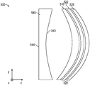
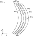
도 4는, 예를 들어 광학 컴포넌트(100)에 대해 기술된 바와 같을 수 있는 광학 스택(420) 및 제1 광학 요소(410)를 포함하는 광학 시스템(400)의 개략 단면도이다. 광학 스택(420)은 제1 및 제2 층들(422, 426)을 포함하며, 이들 중 하나는 반사 편광기일 수 있고, 다른 하나는 비접착성 가요성 광학 층일 수 있다. 제1 및 제2 층들(422, 426)은 (예컨대, 광학적으로 투명한 접착제로) 함께 접합될 수 있고, 광학 스택은 제1 광학 요소(410)에 (예컨대, 광학적으로 투명한 접착제로) 접합될 수 있다. 광학 시스템(400)은, 제1 광학 요소(410)에 인접하고 실질적으로 비평행한 제1 및 제2 주 표면들(443, 444)을 포함하는 제2 광학 요소(440)를 추가로 포함한다. 예시된 실시 형태에서, 제1 광학 요소(410) 및 제2 광학 요소(440)는 접착제 층(434)을 통해 함께 접합된다. 다른 실시 형태에서, 제1 및 제2 광학 요소들(410, 440)은 서로로부터 이격되어 있다. 이는 광학 시스템(500)의 개략 단면도인 도 5에 예시되어 있다. 요소(510, 520, 522, 526)는 각각 요소(410, 420, 422, 426)에 대응한다. 광학 시스템(500)은, 제1 광학 요소(510)에 인접하게 배치되고 그로부터 이격되어 있고 서로 반대편에 있는 제1 및 제2 주 표면들(543, 544)을 갖는 제2 광학 요소(540)를 포함한다. 예시된 실시 형태에서, 제2 주 표면(544)은 실질적으로 평면형이다.4 is a schematic cross-sectional view of an
일부 실시 형태에서, 광학 스택은 제1 광학 요소와 제2 광학 요소 사이에 배치된다. 이는 광학 시스템(600)의 개략 단면도인 도 6a에 예시되어 있다. 요소(610, 620, 622, 626)는 각각 요소(410, 420, 422, 426)에 대응한다. 광학 시스템(600)은, 제1 광학 요소(610)에 인접하게 배치되고 실질적으로 비평행한 제1 및 제2 주 표면들(643, 644)을 갖는 제2 광학 요소(640)를 포함한다. 광학 스택(620)은 제1 광학 요소(610)와 제2 광학 요소(640) 사이에 배치된다. 예시된 실시 형태에서, 광학 스택(620)은 제2 광학 요소(640)의 제2 주 표면(644) 상에 배치되고 그에 정합된다. 다른 실시 형태에서, 광학 스택(620)은 제2 주 표면(644)에 정합되지 않을 수 있고/있거나 제2 광학 요소(640)는 광학 스택(620)으로부터 이격될 수 있다. 예시된 실시 형태에서, 광학 스택(620)은 제1 및 제2 광학 요소들(610, 640) 각각의 주 표면(각각, 611, 644)에 접착된다. 다른 실시 형태에서, 광학 스택(620)은 제1 및 제2 광학 요소들(610, 640) 중 하나에 접착되고 그들 중 다른 하나에는 접착되지 않을 수 있다. 일부 실시 형태에서, 광학 스택(620)은, 예를 들어, 인서트 성형 공정을 통해 제1 및/또는 제2 광학 요소들(610, 640)과 일체로 형성될 수 있다.In some embodiments, the optical stack is disposed between the first optical element and the second optical element. This is illustrated in FIG. 6A, which is a schematic sectional view of the
일부 실시 형태에서, 제2 광학 요소(640)는, 실질적으로 평행한 서로 반대편에 있는 주 표면들을 갖는 제2 광학 층으로 대체된다. 이는 광학 시스템(600b)의 개략 단면도인 도 6b에 예시되어 있다. 광학 시스템(600b)은, 제2 광학 층(640b)이 제2 광학 요소(640) 대신에 사용되는 것을 제외하고는 광학 시스템(600)에 대응한다. 광학 스택(620b)은 제1 및 제2 층들(622, 626) 및 제2 광학 층(640b)을 포함한다. 일부 실시 형태에서, 제1 층(622)은 제1 비접착성 가요성 광학 층이고, 제2 층(626)은 반사 편광기이고, 제2 광학 층(640b)은 제2 비접착성 가요성 광학 층이다. 제2 광학 층(640b)의 서로 반대편에 있는 주 표면들(643b, 644b)은 실질적으로 평행할 수 있다.In some embodiments, the second
일부 실시 형태에서, 제1 광학 요소는 제1 광학 렌즈이고, 제2 광학 요소(포함되어 있는 경우)는 제2 광학 렌즈이다. 일부 실시 형태에서, 제1 광학 렌즈 및 제2 광학 렌즈(포함되어 있는 경우)는, 양면 볼록(biconvex), 평볼록(plano-convex), 정의 메니스커스(positive meniscus), 부의 메니스커스(negative meniscus), 평오목(plano-concave) 또는 양면 오목(biconcave) 렌즈들로 이루어진 군으로부터 독립적으로 선택될 수 있다. 다른 실시 형태에서, 광학 요소(들)는 광학 프리즘이다.In some embodiments, the first optical element is a first optical lens and the second optical element (if included) is a second optical lens. In some embodiments, the first optical lens and the second optical lens (if included) are biconvex, plano-convex, positive meniscus, negative meniscus ( negative meniscus, plano-concave or biconcave lenses. In other embodiments, the optical element(s) is an optical prism.
도 7은 만곡된 제1 주 표면(711)을 갖는 제1 광학 요소(710), 및 만곡된 제1 주 표면(711)에 접합되고 정합되는 광학 스택(720)을 포함하는 광학 컴포넌트(700)의 개략 단면도이다. 광학 스택(720) 및 제1 및 제2 광학 층들(722, 726)은 각각 광학 스택(120) 및 제1 및 제2 광학 층들(722, 726)에 대응할 수 있고 그에 대해 기술된 바와 같을 수 있다. 예를 들어, 일부 실시 형태에서, 제1 및 제2 광학 층들(722, 726) 중 하나는 반사 편광기이고, 제1 및 제2 광학 층들(722, 726) 중 다른 하나는 비접착성 가요성 광학 층이다. 광학 컴포넌트(700)는 광학 시스템 내의 컴포넌트일 수 있거나, 또는 광학 시스템 그 자체인 것으로 간주될 수 있다. 일부 실시 형태에서, 광학 컴포넌트(700)는 편광 빔 스플리터(PBS)이다.7 shows an
예시된 실시 형태에서, 제1 광학 요소(710)는 제1 및 제2 면들(712, 713), 및 제1 만곡된 주 표면(711)을 갖는 빗면을 갖는 제1 광학 프리즘이다. 제1 면(712)과 제2 면(713) 사이의 각도(α1)는 약 85도 내지 약 95도의 범위에 있을 수 있다. 제1 면(712)과 제1 만곡된 주 표면(711) 사이의 각도(α2)는 약 40도 내지 약 50도의 범위에 있을 수 있고, 제2 면(713)과 제1 만곡된 주 표면(711) 사이의 각도(α3)는 약 40도 내지 약 50도의 범위에 있을 수 있다. 일부 실시 형태에서, 제1 광학 요소(710)는, 실질적으로 직교하는 제1 및 제2 면들(712, 713), 및 제1 및 제2 면들(712, 713) 각각과 실질적으로 45도(예컨대, 40도 내지 50도)로 교차하는 빗면(제1 만곡된 주 표면(711)을 갖는 면)을 갖는다.In the illustrated embodiment, the first
광학 요소의 제1 주 표면과 제2 주 표면 사이의 각도는, 예를 들어 제1 주 표면과 제2 주 표면이 에지에서 만나는 실시 형태에서 이들이 만나는 표면들 사이의 각도이다. 제1 및 제2 주 표면들이 만나지 않고 광학 요소의 부 표면을 제공하는 광학 요소의 에지에서 서로 분리되어 있는 실시 형태에서, 제1 주 표면과 제2 주 표면 사이의 각도는, 에지에서의 제1 및 제2 주 표면들에 접하는 선들 사이의 각도로서 정의될 수 있다. 이는 제1 및 제2 주 표면들(2011, 2012)을 갖는 광학 요소(2010)의 개략 단면도인 도 20에 예시되어 있다. 제1 및 제2 주 표면들(2010, 2011)은 그들 사이에 각도(φ)를 형성한다. 일부 실시 형태에서, φ는 약 45도 미만 또는 약 35도 미만이다. 일부 실시 형태에서, φ는 약 10도 초과 또는 약 20도 초과이다.The angle between the first major surface and the second major surface of the optical element is, for example, the angle between the surfaces they meet in an embodiment where the first major surface and the second major surface meet at the edge. In embodiments in which the first and second major surfaces do not meet and are separated from each other at the edge of the optical element that provides the minor surface of the optical element, the angle between the first and second major surfaces is the first at the edge. And angles between lines abutting the second major surfaces. This is illustrated in FIG. 20, which is a schematic cross-sectional view of
일부 실시 형태에서, 광학 요소의 제1 및 제2 주 표면들은 그들 사이에 약 20도 내지 약 120도의 범위의 각도를 형성한다. 프리즘의 경우에, 각도는, 예를 들어 프리즘의 기하학적 구조, 및 프리즘의 어느 면(제1 주 표면) 상에 광학 스택 또는 반사 편광기가 배치되는지에 따라 약 45도 또는 약 90도일 수 있다. 광학 렌즈의 경우에, 각도는, 예를 들어 약 20도 내지 약 40도일 수 있다.In some embodiments, the first and second major surfaces of the optical element form an angle between about 20 degrees and about 120 degrees between them. In the case of a prism, the angle can be, for example, about 45 degrees or about 90 degrees, depending on the geometry of the prism, and on which side of the prism (the first major surface) the optical stack or reflective polarizer is placed. In the case of an optical lens, the angle can be, for example, from about 20 degrees to about 40 degrees.
도 8은, 제1 빗면(811)을 갖는 제1 프리즘(810); 제1 빗면(811)에 대면하는 제2 빗면(844)을 갖는 제2 프리즘(840); 및 제1 빗면(811)과 제2 빗면(844) 사이에 배치되고 그에 접착된 광학 스택(820)을 포함하는 편광 빔 스플리터(800)의 개략 단면도이다. 광학 스택(820)은 접착제 층(832)을 통해 제1 빗면(811)에 접착되고 접착제 층(834)을 통해 제2 빗면(844)에 접착된다. 광학 스택(820)의 제1 및 제2 층들(822, 826)은 접착제 층(830)을 통해 서로 접착된다. 광학 스택(820)은, 예를 들어 광학 스택(120)에 대응할 수 있다. 예를 들어, 일부 실시 형태에서, 광학 스택(820)은, 제1 편광 상태를 갖는 광을 실질적으로 투과시키고 직교하는 제2 편광 상태를 갖는 광을 실질적으로 반사시키는 반사 편광기(제1 및 제2 층들(822, 826) 중 하나); 및 반사 편광기에 접합되고, 실질적으로 평행한 서로 반대편에 있는 제1 및 제2 주 표면들을 갖는 비접착성 가요성 광학 층(제1 및 제2 층들(822, 826)들 중 다른 하나)을 포함한다. 접착제 층(830)은 반사 편광기와 비접착성 가요성 광학 층 사이에 배치되고 반사 편광기를 비접착성 가요성 광학 층에 접합한다.8 shows a
도 9는, 제1 및 제2 프리즘들(910, 940)의 빗면이 실질적으로 평면형이고 광학 스택(920)이 실질적으로 평면형인 것을 제외하고는 많은 방식으로 편광 빔 스플리터(800)와 유사한 편광 빔 스플리터(900)의 개략 단면도이다. 광학 스택(920)의 층은, 광학 스택(920)의 층이 실질적으로 평면형인 것을 제외하고는 광학 스택(820)에 대해 기술된 바와 같을 수 있다. 예를 들어, 광학 스택(920)은, 접착제 층을 통해 함께 접합된 반사 편광기 및 비접착성 가요성 광학 층을 포함할 수 있다. 광학 스택(920)은, 각각의 접착제 층을 통해 제1 및 제2 프리즘들(910, 940) 각각에 접합될 수 있다.FIG. 9 shows a polarization beam similar to the
일부 실시 형태에서, 광학 스택(820 또는 920)은 제2 비접착성 가요성 광학 층을 포함한다. 예를 들어, 광학 스택(820 또는 920)은 광학 스택(620b)에 대응할 수 있고, 제1 비접착성 가요성 광학 층과 제2 비접착성 가요성 광학 층 사이에 배치된 반사 편광기를 포함할 수 있다.In some embodiments,
일부 실시 형태에서, 편광 빔 스플리터는 제1 및 제2 프리즘들을 포함하며, 여기서 프리즘들 중 하나는 만곡된 빗면을 가지며 다른 하나의 프리즘은 실질적으로 평면인 빗면을 갖는다. 이러한 경우에, 광학 스택은 하나의 빗면에 정합할 수 있거나, 또는 어떠한 빗면에도 정합하지 않을 수 있고, 광학 스택을, 그것이 정합하지 않는 빗면에 접합하기 위해 불균일한 두께를 갖는 접착제 층이 사용될 수 있다.In some embodiments, the polarizing beam splitter includes first and second prisms, where one of the prisms has a curved bevel and the other prism has a substantially planar bevel. In this case, the optical stack can be mated to one bevel, or not to any bevel, and an adhesive layer having a non-uniform thickness can be used to bond the optical stack to the bevel that it does not match. .
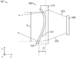
도 10은 렌즈 조립체(1000) 및 디스플레이 패널(1050)을 포함하는 광학 시스템(1001)의 개략 단면도이다. 렌즈 조립체(1000)는 만곡된 제1 주 표면(1011) 및 적어도 하나의 방향에서의 광학 굴절력을 갖는 제1 광학 렌즈(1010)를 포함한다. 렌즈 조립체(1000)는 제1 주 표면(1011) 상에 배치된 광학 층(1020)을 추가로 포함한다. 일부 실시 형태에서, 광학 층(1020)은 제1 주 표면(1011)에 접착되고 그에 정합된다. 일부 실시 형태에서, 광학 층(1020)은 본 명세서의 어딘가 다른 곳에 기술된 임의의 광학 스택이다. 예를 들어, 일부 실시 형태에서, 광학 층(1020)은 제1 편광 상태를 갖는 광을 실질적으로 투과시키고 직교하는 제2 편광 상태를 갖는 광을 실질적으로 반사시키는 반사 편광기를 포함하고; (예컨대, 접착제 층을 통해) 반사 편광기에 접합되고 실질적으로 평행한 서로 반대편에 있는 제1 및 제2 주 표면들을 갖는 비접착성 가요성 광학 층을 포함한다. 일부 실시 형태에서, 광학 층(1020)은 복수의 간섭 층을 포함하는 일체로 형성된 반사 편광기이며, 여기서 각각의 간섭 층은 주로 광학 간섭에 의해 광을 반사시키거나 투과시킨다. 일부 실시 형태에서, 반사 편광기는 제1 광학 렌즈(1010)의 제1 주 표면(1011)에 접착된다.10 is a schematic cross-sectional view of an
디스플레이 패널(1050)은, 최대 투영된 치수(D) 및 대응하는 최대 새그(S)를 갖는 제1 주 표면(1011)의 활성 영역을 결정하는 광(1073)을 방출한다. D는, 평면에 걸쳐 그리고 평면 내의 치수들에 걸쳐 최대화된, 평면 상으로의 활성 영역의 투영의 최대 치수이다. S는, 투영된 치수가 최대화되는 평면에 직교하는 방향으로 측정되는 최대 새그이다. 예시된 실시 형태에서, 투영된 치수는 z-축을 따른 S 및 x-y 평면에서의 최대값이다. 광학 시스템(1001)이 광학 축을 갖는 실시 형태에서, 최대 투영된 치수는 전형적으로, 투영이 광학 축에 수직인 평면 상으로의 것일 때 발생하고, 최대 새그는 전형적으로 광학 축을 따른다. 일부 실시 형태에서, S/D는 약 0.03 이상, 또는 약 0.05 이상, 또는 약 0.1 이상이다. 일부 실시 형태에서, S/D는 약 0.5 이하이다.The
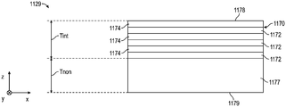
도 11은 복수의 간섭 층(1170) 및 비간섭 층(1177)을 포함하는 일체로 형성된 반사 편광기(1129)의 개략 단면도이다. 일부 실시 형태에서, 복수의 간섭 층은 교번하는 중합체 층(1172, 1174)을 포함한다. 예시된 실시 형태에서, 단일 비간섭 층(1177)이 포함된다. 간섭 층은, 간섭 층의 반사율 및 투과율이 광학 간섭에 의해 합리적으로 기술될 수 있거나 또는 광학 간섭으로부터 야기되는 것으로 합리적으로 정확하게 모델링될 수 있을 때 주로 광학 간섭에 의해 광을 반사 또는 투과시키는 것으로 기술될 수 있다. 그러한 간섭 층은, 예를 들어, 미국 특허 제5,882,774호(Jonza 등), 및 미국 특허 제6,609,795호(Weber 등)에 기술되어 있다. 상이한 굴절률을 갖는 간섭 층의 인접한 쌍은, 그 쌍이, 조합된 광학 두께(굴절률 × 물리적 두께)가 광의 파장의 1/2일 때 광학 간섭에 의해 광을 반사시킨다. 간섭 층은 전형적으로 물리적 두께가 약 200 나노미터 미만이다. 비간섭 층은, 간섭을 통한 가시광의 반사에 기여하기에는 너무 큰 광학 두께를 갖는다. 전형적으로, 비간섭 층은 물리적 두께가 1 마이크로미터 이상이다. 일부 실시 형태에서, 하나 초과의 비간섭 층이 포함된다. 일부 실시 형태에서, 복수의 간섭 층(1170)은 적어도 하나의 비간섭 층(1177)의 동일한 면 상에 배치된다. 일부 실시 형태에서, 적어도 하나의 비간섭 층(예시된 실시 형태에서의 비간섭 층(1177))은 복수의 간섭 층(1170)과 일체로 형성되고, 주로 광학 간섭에 의해 광을 반사시키거나 투과시키지 않는다. 일부 실시 형태에서, 비간섭 층(1177)은 본 명세서의 어딘가 다른 곳에서 추가로 기술되는 바와 같은 비접착성 가요성 광학 층이다. 일부 실시 형태에서, 반사 편광기(1129)는, 본 명세서의 어딘가 다른 곳에서 추가로 기술되는 바와 같이, 제1 주 면(1178)으로부터 입사하는 차단 상태의 광에 대한 반사율이, 제2 주 면(1179)으로부터 입사하는 차단 상태의 광에 대한 반사율과는 상이하다.11 is a schematic cross-sectional view of an integrally formed
복수의 간섭 층(1170)의 평균 총 두께는 Tint이고, 적어도 하나의 비간섭 층(1177)의 평균 총 두께는 Tnon이다. 일부 실시 형태에서, Tint는 약 20 마이크로미터 내지 약 70 마이크로미터의 범위 내에 있고, Tnon은 약 40 마이크로미터 내지 약 100 마이크로미터의 범위 내에 있다. 총 두께는, 예를 들어 하나 이상의 비간섭 층의 표면이 구조화되는 경우에 변할 수 있다. 총 두께는 또한, 예를 들어 통상의 제조 변동으로 인해 변할 수 있다. 평균 총 두께는 층의 면적에 걸친 두께의 비가중 평균이다. 일부 실시 형태에서, 반사 편광기의 평균 총 두께(Tint+Tnon)는 50 마이크로미터 이상, 60 마이크로미터 이상, 또는 70 마이크로미터 이상이다. 일부 실시 형태에서, 반사 편광기(1129)는 실질적으로 일축 배향된다. 일부 실시 형태에서, 층(1172)은, 예를 들어 x-축을 따라 실질적으로 일축 배향되고, 층(1174)은 실질적으로 등방성이다. 이 경우에, 수직 입사광에 대한 차단 편광 상태는 전형적으로, 광이 x-축을 따라 편광된 편광 상태이고, 수직 입사광에 대한 통과 편광 상태는 전형적으로, 광이 y-축을 따라 편광된 편광 상태이다.The average total thickness of the plurality of
도 12는 복수의 간섭 층(1270), 및 복수의 간섭 층(1270)과 일체로 형성된 적어도 하나의 비간섭 층(1277a, 1277b)을 포함하는 광학 필름(1229)의 개략도이다. 적어도 하나의 비간섭 층(1277a, 1277b)의 평균 총 두께는 비간섭 층(1277a, 1277b)의 두께의 합계이다. 광학 필름(1229)은, 예를 들어 광학 렌즈와 같은 광학 요소에 이 필름을 접착하는 데 사용될 수 있는 접착제 층(1232)을 추가로 포함한다. 광학 필름(1229)은 복수의 간섭 층(1270)의 각각의 면 상에 적어도 하나의 비간섭 층을 포함한다. 일부 실시 형태에서, 미리결정된 파장 범위에서의 실질적 수직 입사광에 대해, 복수의 간섭 층(1270)은 제1 편광 상태에 대한 평균 광학 투과율이 약 85% 초과이고 직교하는 제2 편광 상태에 대한 평균 광학 반사율이 약 80% 초과이다.12 is a schematic diagram of an
도 13은 제1 패킷(1370-1) 및 제2 패킷(1370-2)으로 배열되는 복수의 간섭 층, 및 복수의 간섭 층과 일체로 형성된 복수의 비간섭 층(1377a, 1377b, 1277c)을 포함하는 광학 필름(1329)의 개략도이다. 적어도 하나의 비간섭 층(1377b)이 복수의 간섭 층 중 2개의 간섭 층들(1370a, 1370b) 사이에 배치된다. 광학 필름(1329)은, 본 명세서의 어딘가 다른 곳에서 추가로 기술되는 바와 같이 평균 광학 투과율 및 반사율을 갖는 반사 편광기일 수 있다. 일부 실시 형태에서, 제1 패킷(1370-1) 및 제2 패킷(1370-2)은, 중첩되는 두께 분포를 갖는다.13 illustrates a plurality of interference layers arranged in the first packet 1370-1 and the second packet 1370-2, and a plurality of
일부 실시 형태에서, 광학 필름(1229 또는 1329)은, 실질적으로 일축 배향되고 반사 편광기의 평균 총 두께(Tint+Tnon)가 50 마이크로미터 이상, 또는 60 마이크로미터 이상, 또는 70 마이크로미터 이상인 반사 편광기이다.In some embodiments, the
일부 실시 형태에서, 적어도 하나의 비간섭 층은, 실질적으로 평행한 서로 반대편에 있는 제1 및 제2 주 표면들을 포함하는 비접착성 가요성 광학 층을 포함하며, 비접착성 가요성 광학 층은 본 명세서의 어딘가 다른 곳에 기술된 범위(예컨대, 100 nm 미만 또는 200 nm 초과) 중 임의의 범위의 광학 지연도를 갖는다.In some embodiments, the at least one non-interfering layer comprises a non-adhesive flexible optical layer comprising first and second major surfaces that are substantially parallel to each other and opposite, wherein the non-adhesive flexible optical layer is It has an optical retardation in any of the ranges described elsewhere herein (eg, less than 100 nm or more than 200 nm).
일부 실시 형태에서, 반사 편광기는 N개의 순차적으로 번호부여된 층을 포함하며, 이때 각각의 층은 두께가 약 200 nm 미만이다. 예를 들어, 간섭 층(1170)은, 비간섭 층(1177)에 바로 인접한 층에 대한 1에서 제1 주 면(1178)에 바로 인접한 층에 대한 N까지 순차적으로 번호가 부여될 수 있다. 일부 실시 형태에서, N은 200 초과 약 800 미만의 정수이다. 도 14a는 층 수의 함수로서의 층 두께(1407)를 개략적으로 예시한다. 평균 기울기(m)를 갖는 피팅된 곡선(1409)이 또한 예시되어 있다. 피팅된 곡선(1409)은 층 수의 함수로서의 반사 편광기의 층 두께에 적용되는 최적 회귀(best-fit regression)이다. 일부 실시 형태에서, 제1 층으로부터 제N 층까지 연장되는 영역에서의 피팅된 곡선의 평균 기울기(m)는 약 0.2 nm 미만이다. 일부 실시 형태에서, N개의 순차적으로 번호부여된 층은, 반사 편광기 내의 스택/패킷의 일부를 형성하지 않는 임의의 비간섭 층, 스페이서 층, 또는 다른 선택적인 광학 층을 배제한다. 일부 실시 형태에서, 피팅된 곡선(1409)은 최적 선형 회귀, 최적 비-선형 회귀, 최적 다항 회귀, 및 최적 지수 회귀 중 하나 이상이다. 일부 실시 형태에서, 최적 회귀는 선형 최소 제곱 피팅(linear least-squares fit)이고, 평균 기울기는 선형 최소 제곱 피팅의 기울기이다. 일부 실시 형태에서, 추가 층이 층 수 1에 인접한 단부 및/또는 층 수 N의 단부에 포함된다. 추가 층은, 예를 들어, 제1 층으로부터 제N 층까지의 대략 선형 추세선을 따르지 않을 수 있고, 미국 특허 출원 공개 제2005/0243425호(Wheatley 등)에 기재된 바와 같이 예리한 대역 에지를 제공하도록 포함될 수 있다.In some embodiments, the reflective polarizer comprises N sequentially numbered layers, each layer having a thickness of less than about 200 nm. For example, the interfering
일부 실시 형태에서, 반사 편광기는 복수의 패킷(예컨대, 패킷(1370-1, 1370-2))을 포함하며, 여기서 각각의 패킷은, 실질적으로 연속적인 곡선인 층 두께 대 층 수를 갖는다. 도 14b는 2개의 패킷(패킷 1 및 패킷 2)을 포함하는 반사 편광기에 대한 층 두께 대 층 수를 예시한다. 일부 실시 형태에서, 두께 프로파일은 실질적으로 중첩된다(예컨대, 패킷 1의 두께 범위의 50% 초과가 패킷 2의 두께 범위의 50% 초과와 중첩된다). 다른 실시 형태에서, 두께 범위에서의 중첩이 거의 또는 전혀 없다. 도 14b에서, 2개의 패킷에 대한 두께 프로파일은 실질적으로 중첩된다. 도 14c는 2개의 패킷(패킷 1 및 패킷 2)을 포함하는 반사 편광기에 대한 층 두께 대 층 수를 예시하며, 여기서 2개의 패킷의 두께 범위에서는 중첩이 거의 또는 실질적으로 전혀 없다. 도 14b에서, 제1 패킷의 간섭 층은 1에서 325까지 번호가 부여되고, 제2 패킷의 간섭 층은 326에서 700까지 번호가 부여된다. 도 14c에서, 제1 및 제2 패킷들 각각의 간섭 층은 1에서 325까지 번호가 부여된다. 일부 실시 형태에서, 각각의 패킷은, 두께 프로파일에 대한 피팅된 곡선의 평균 기울기(m)가 약 0.2 nm 미만인 층 두께 프로파일을 갖는다.In some embodiments, the reflective polarizer includes a plurality of packets (eg, packets 1370-1, 1370-2), where each packet has a layer thickness versus number of layers that is a substantially continuous curve. 14B illustrates layer thickness versus number of layers for a reflective polarizer comprising two packets (
일부 실시 형태에서, 층 두께 프로파일은, 순차적으로 번호부여된 간섭 층의 층 수의 함수로서 각각의 패킷의 두께 프로파일에 적용되는 최적 선형 방정식에 의해 특징지어질 수 있다. 일부 실시 형태에서, 각각의 패킷은 유사한 기울기(예컨대, 서로의 20% 이내)를 갖는 최적 두께 프로파일을 갖는다. 일부 실시 형태에서, 반사 편광기 내의 모든 패킷에 대한 최적 선형 회귀의 평균 기울기들 간의 최대 차이는 약 20% 미만이다. 그러한 반사 편광기는 2017년 3월 6일자로 출원된 미국 가특허 출원 제62/467712호(Haag 등)에 추가로 기재되어 있다.In some embodiments, the layer thickness profile can be characterized by an optimal linear equation applied to the thickness profile of each packet as a function of the number of layers of sequentially numbered interfering layers. In some embodiments, each packet has an optimal thickness profile with similar slopes (eg, within 20% of each other). In some embodiments, the maximum difference between the average slopes of the optimal linear regression for all packets in the reflective polarizer is less than about 20%. Such reflective polarizers are further described in U.S. Provisional Patent Application No. 62/467712 (Haag et al.), filed March 6, 2017.
도 15는 만곡된 제1 주 표면(1511)을 갖는 제1 광학 렌즈(1510), 서로 반대편에 있는 최외부 제1 및 제2 주 표면들(1563, 1567)을 갖는 광학 필름(1520), 및 광학 필름(1520)의 제1 주 표면(1523)을 제1 광학 렌즈(1510)의 제1 주 표면(1511)에 접합하는 접착제 층(1532)을 포함하는 렌즈 조립체(1500)의 개략 단면도이다. 일부 실시 형태에서, 제1 광학 렌즈(1510)의 제1 주 표면(1511)은 원치 않는 특징(예컨대, 곡률 또는 표면 조도)을 가지며, 접합은 제1 광학 렌즈(1510)의 제1 주 표면(1511)의 원치 않는 특징을 보상한다. 일부 실시 형태에서, 광학 필름(1520)은 본 명세서의 어딘가 다른 곳에서 추가로 기술되는 바와 같이 반사 편광기 및 반사 편광기에 접합되는 비접착성 가요성 광학 층을 포함하는 광학 스택이다. 일부 실시 형태에서, 광학 필름(1520)은 일체로 형성된 반사 편광기이거나 이를 포함한다. 일부 실시 형태에서, 일체로 형성된 반사 편광기는 복수의 간섭 층을 포함하며, 각각의 간섭 층은 주로 광학 간섭에 의해 광을 반사시키거나 투과시킨다.15 is a first
일부 실시 형태에서, 제1 광학 렌즈(1510)의 제1 주 표면(1511)은, 표면 곡률을 포함하는 원치 않는 특징을 갖는다. 예를 들어, 일부 실시 형태에서, 제1 광학 렌즈(1510)의 만곡된 제1 주 표면(1511)은 원치 않는 곡률 1/R1을 가지며, 여기서 R1은 제1 주 표면(1511)의 곡률 반경이다. 일부 실시 형태에서, 광학 필름(1520)을 제1 주 표면(1511)에 접합하는 것은 원치 않는 곡률을 보상하는데, 이는 광학 필름(1520)의 최외부 제2 주 표면(1567)이 원하는 곡률 1/R2를 가질 수 있기 때문이며, 여기서 R2는 최외부 제2 주 표면(1567)의 곡률 반경이다.In some embodiments, the first
도 16은 만곡된 제1 주 표면(1611)을 갖는 제1 광학 렌즈(1610); 복수의 간섭 층을 포함하고 - 각각의 간섭 층은 주로 광학 간섭에 의해 광을 반사시키거나 투과시킴 -, 서로 반대편에 있는 최외부 제1 및 제2 주 표면들(1663, 1667)을 갖는 일체로 형성된 반사 편광기(1620); 및 일체로 형성된 반사 편광기(1620)의 제1 주 표면(1623)을 제1 광학 렌즈(1610)의 제1 주 표면(1611)에 접합하는 접착제 층(1632)을 포함하는 렌즈 조립체(1600)의 개략 단면도이다. 예시된 실시 형태에서, 제1 광학 렌즈(1610)의 제1 주 표면(1611)은 평균 표면 조도를 포함하는 원치 않는 특징을 갖는다. 일체로 형성된 반사 편광기(1620)를 제1 광학 렌즈(1610)에 접합하는 것은, 원하는 평균 표면 조도를 제공함으로써 제1 광학 렌즈(1610)의 제1 주 표면(1611)의 원치 않는 평균 표면 조도를 보상한다. 일부 실시 형태에서, 일체로 형성된 반사 편광기는, 반사 편광기를 포함하는 본 명세서의 어딘가 다른 곳에 기술된 광학 스택으로 대체되고, 적어도 하나의 비접착성 가요성 광학 층이 제1 광학 렌즈에 접합된다. 제1 광학 렌즈의 반대편에 있는 광학 스택의 최외부 주 표면은 최외부 제2 표면(1667)에 대해 본 명세서에 기술된 특성을 가질 수 있다.16 is a first
일부 실시 형태에서, 평균 표면 조도는, 평균 표면(표면 조도를 무시한 매끄러운 표면)으로부터의 표면의 편차의 절대값의 평균인 조도 파라미터(Ra)이다. 일부 실시 형태에서, 제1 주 표면(1611)은 평균 표면 조도(Ra)가 약 200 nm 초과, 또는 약 150 nm 초과이고, 최외부 제2 표면(1667)은 표면 조도(Ra)가 약 100 nm 미만, 또는 약 50 nm 미만이다. 일부 실시 형태에서, 제1 주 표면(1611)은 광학적으로 매끄럽지 않고(예컨대, 광이 표면 조도로 인해 산란될 수 있음), 제2 주 표면(1667)은 광학적으로 매끄럽다.In some embodiments, the average surface roughness is the roughness parameter Ra, which is the average of the absolute values of the deviations of the surface from the average surface (smooth surface ignoring the surface roughness). In some embodiments, the first
일부 실시 형태에서, 렌즈 조립체 또는 광학 스택 또는 광학 시스템 내의 2개 이상의 층(예컨대, 2개의 바로 인접한 층)은 실질적으로 굴절률 매칭된다. 실질적으로 굴절률 매칭된 층은, 굴절률들의 차이의 절대값이 약 0.20 미만이 되도록 하는 굴절률을 갖는다. 굴절률은, 달리 명시되지 않는 한, 550 nm의 파장에서 결정된다.In some embodiments, two or more layers (eg, two immediately adjacent layers) in a lens assembly or optical stack or optical system are substantially refractive index matched. The substantially matched refractive index layer has a refractive index such that the absolute value of the difference between the refractive indices is less than about 0.20. The refractive index is determined at a wavelength of 550 nm, unless otherwise specified.
일부 실시 형태에서, 제1 광학 렌즈(1610)의 굴절률과 접착제 층(1632)의 굴절률 간의 차이의 절대값은 약 0.20 미만, 또는 약 0.15 미만, 또는 약 0.10 미만, 또는 약 0.08 미만, 또는 약 0.06 미만, 또는 약 0.04 미만, 또는 약 0.02 미만, 또는 약 0.01 미만일 수 있다. 접착제 층이 광학 스택 또는 반사 편광기를 렌즈 또는 프리즘과 같은 광학 요소에 접합하는 본 명세서에 기술된 실시 형태들 중 임의의 실시 형태에서, 광학 요소의 굴절률과 접착제 층의 굴절률 간의 차이의 절대값은 이들 범위 중 임의의 범위에 있을 수 있다.In some embodiments, the absolute value of the difference between the refractive index of the first
일부 실시 형태에서, 본 발명의 광학 필름(예컨대, 광학 스택, 반사 편광기), 또는 광학 필름 내의 복수의 간섭 층은 제1 편광 상태에 대한 평균 광학 투과율이 약 85% 초과이고, 직교하는 제2 편광 상태에 대한 평균 광학 반사율이 약 80% 초과이다. 일부 실시 형태에서, 광학 필름의 일 면 또는 양 면들로부터 광학 필름 상에 수직으로 입사하는 광에 대해 제1 편광 상태에 대한 평균 광학 투과율은 약 85% 초과이다. 일부 실시 형태에서, 광학 필름의 일 면 또는 양 면들로부터 광학 필름 상에 수직으로 입사하는 광에 대해 제2 편광 상태에 대한 평균 광학 반사율은 약 80% 초과이다. 일부 실시 형태에서, 광학 필름은 제2 편광 상태에 대한 평균 광학 흡수가 약 2%, 또는 5%, 또는 10% 초과여서, 미리결정된 파장 범위에서의 실질적 수직 입사광에 대해, 광학 필름은 광학 필름의 제1 주 면으로부터 입사하는 광에 대한 더 큰 평균 광학 반사율 및 광학 필름의 반대편 제2 주 면으로부터 입사하는 광에 대한 더 작은 평균 광학 반사율을 갖게 된다. 다른 실시 형태에서, 평균 광학 흡수는 약 1% 미만이어서, 평균 광학 투과율 및 평균 광학 반사율이 광학 필름의 어느 하나의 면에서 대략 동일하도록 된다. 예를 들어, 도 11을 참조하면, 비간섭 층(1177)에 더 가까운 간섭 층(1170)의 일부는 비간섭 층(1177)으로부터 더 먼 층보다 제2 편광 상태에 대한 흡수율이 더 높을 수 있어서, 광학 필름은 제1 주 면(1178) 상에 입사하는 제2 편광 상태를 갖는 광에 대한 평균 반사율이 제2 주 면(1179) 상에 입사하는 제2 편광 상태를 갖는 광의 더 높은 흡수로 인해 제2 주 면(1179) 상에 입사하는 제2 편광 상태를 갖는 광에 대한 것보다 더 크게 된다.In some embodiments, the optical film of the present invention (eg, optical stack, reflective polarizer), or a plurality of interfering layers in an optical film has an average optical transmittance for a first polarization state of greater than about 85%, orthogonal second polarization The average optical reflectance for the state is greater than about 80%. In some embodiments, the average optical transmittance for the first polarization state is greater than about 85% for light incident perpendicularly onto the optical film from one or both sides of the optical film. In some embodiments, the average optical reflectance for the second polarization state is greater than about 80% for light incident vertically on one or both sides of the optical film on the optical film. In some embodiments, the optical film has an average optical absorption for a second polarization state of greater than about 2%, or 5%, or 10%, such that for substantially normal incident light in a predetermined wavelength range, the optical film is It has a larger average optical reflectance for light incident from the first major plane and a smaller average optical reflectance for light incident from the second major plane opposite the optical film. In other embodiments, the average optical absorption is less than about 1%, such that the average optical transmittance and average optical reflectance are approximately the same on either side of the optical film. For example, referring to FIG. 11, a portion of the interfering
광학 필름의 서로 반대편에 있는 주 면들 상에 입사하는 광의 평균 광학 반사율의 차이는, 광학 필름의 복수의 간섭 층 중의 적어도 일부 층에 광 흡수 분자를 포함시킴으로써 달성될 수 있다. 일부 실시 형태에서, 복수의 간섭 층은 실질적으로 제2 편광 상태를 따라 배향된 복수의 광 흡수 분자를 포함한다. 일부 실시 형태에서, 복수의 광 흡수 분자는 적어도 부분적으로 미리결정된 파장 범위 내의 흡수 대역을 갖는다. 광 흡수 분자는, 필름을 연신(예컨대, 실질적으로 일축 연신)함으로써 필름을 배향하기 전에 필름 내의 층 중 적어도 일부에 광 흡수 분자를 포함시킴으로써 그를 따라 배향될 수 있다. 이어서, 광 흡수 분자는 필름이 연신될 때 정렬될 수 있다. 일부 실시 형태에서, 복수의 간섭 층은 복수의 교번하는 더 높은 굴절률의 제1 층 및 더 낮은 굴절률의 제2 층을 포함한다. 예를 들면, 층(1174)은 더 높은 굴절률의 층일 수 있고, 층(1172)은 더 낮은 굴절률의 층일 수 있다. 일부 실시 형태에서, 제1 층은, 미리결정된 파장 범위 내의 적어도 하나의 파장에 대해 제2 층보다 실질적으로 더 큰 광 흡수성이다. 예를 들어, 제1 층은 흡수율이 제2 층의 흡수율의 2배 이상, 또는 5배 이상, 또는 10배 이상일 수 있다. 일부 실시 형태에서, 제1 층은 실질적으로 더 높은 농도의 광 흡수 분자를 갖고, 제2 층은 실질적으로 더 낮은 농도의 광 흡수 분자를 갖는다. 광 흡수 분자를 포함하는 반사 편광기는, 예를 들어 미국 특허 출원 공개 제2016/0306086호(Haag 등) 및 미국 특허 제6,096,375호(Ouderkirk 등)에 기재되어 있으며, 이들 각각은 본 발명에 모순되지 않는 정도로 본 명세서에 참고로 포함된다.The difference in the average optical reflectance of light incident on major opposing sides of the optical film can be achieved by including light absorbing molecules in at least some of the plurality of interfering layers of the optical film. In some embodiments, the plurality of interfering layers comprises a plurality of light absorbing molecules oriented substantially along a second polarization state. In some embodiments, the plurality of light absorbing molecules has an absorption band at least partially within a predetermined wavelength range. The light absorbing molecules can be oriented accordingly by including the light absorbing molecules in at least a portion of the layers in the film before orienting the film by stretching (eg, substantially uniaxially stretching) the film. The light absorbing molecules can then be aligned when the film is stretched. In some embodiments, the plurality of interfering layers includes a plurality of alternating higher refractive index first layers and a lower refractive index second layer. For example,
적합한 광 흡수 분자에는 일본 소재의 Mitsui Fine Chemicals로부터 입수가능한 안트라퀴논 염료, 아조 염료, 및 이색성 염료(예컨대, PD-325H, PD-335H, PD-104 및 PD-318H)가 포함된다. 복수의 광 흡수 분자는 복수의 공통 유형의 분자(예컨대, 단일 유형의 이색성 염료)일 수 있거나, 또는 복수의 상이한 유형의 분자(예컨대, 이색성 염료의 혼합물)를 포함할 수 있다.Suitable light absorbing molecules include anthraquinone dyes, azo dyes, and dichroic dyes (eg PD-325H, PD-335H, PD-104 and PD-318H) available from Mitsui Fine Chemicals of Japan. The plurality of light absorbing molecules can be a plurality of common types of molecules (eg, a single type of dichroic dye), or can include a plurality of different types of molecules (eg, a mixture of dichroic dyes).
도 17은 반사 편광기의 일 면으로부터 반사 편광기 상에 수직으로 입사하는 광에 대해 반사 편광기의 통과 상태 및 차단 상태에 대한 반사 편광기의 투과율의 개략 플롯이다. 투과율은 반사 편광기의 다른 면으로부터 반사 편광기 상에 수직으로 입사하는 광에 대해 실질적으로 동일할 수 있다. λ1 내지 λ2의 미리결정된 파장 범위 내의 파장들에 걸친 투과율의 평균은 통과 상태에서 Tp이고, 차단 상태에서 Tb이다. 일부 실시 형태에서, λ1은 약 400 nm이고, λ2는 약 700 nm이다. 일부 실시 형태에서, Tp는 약 80% 초과, 또는 약 85% 초과, 또는 90% 초과이다. 일부 실시 형태에서, Tb는 약 10% 이하, 또는 약 5% 이하, 또는 약 2% 이하, 또는 약 1% 이하, 또는 약 0.5% 이하이다. 일부 실시 형태에서, 반사 편광기의 일 면 상에 입사하는 광에 대한 Tp 및 Tb는 이들 조건 중 적어도 하나를 만족하고, 일부 실시 형태에서, 반사 편광기의 각각의 면 상에 입사하는 광에 대한 Tp 및 Tb는 이들 조건 중 적어도 하나를 만족한다.17 is a schematic plot of the transmittance of a reflective polarizer with respect to a pass state and a blocked state of the reflective polarizer for light incident perpendicularly onto the reflective polarizer from one side of the reflective polarizer. The transmittance can be substantially the same for light incident vertically onto the reflective polarizer from the other side of the reflective polarizer. The average of transmittance over wavelengths within a predetermined wavelength range of λ1 to λ2 is Tp in the pass state and Tb in the cutoff state. In some embodiments, λ1 is about 400 nm and λ2 is about 700 nm. In some embodiments, Tp is greater than about 80%, or greater than about 85%, or greater than 90%. In some embodiments, Tb is about 10% or less, or about 5% or less, or about 2% or less, or about 1% or less, or about 0.5% or less. In some embodiments, Tp and Tb for light incident on one side of the reflective polarizer satisfy at least one of these conditions, and in some embodiments, Tp and Tp for light incident on each side of the reflective polarizer Tb satisfies at least one of these conditions.
도 18은 반사 편광기의 일 면으로부터 반사 편광기 상에 수직으로 입사하는 광에 대해 반사 편광기의 통과 상태 및 차단 상태에 대한 반사 편광기의 반사율의 개략 플롯이다. 반사율은 반사 편광기의 다른 면으로부터 반사 편광기 상에 수직으로 입사하는 광에 대해 실질적으로 동일할 수 있거나, 또는, 예를 들어 이색성 염료의 존재로 인해 상이할 수 있다. λ1 내지 λ2의 미리결정된 파장 범위 내의 파장들에 걸친 반사율의 평균은 통과 상태에서 Rp이고, 차단 상태에서 Rb이다. 일부 실시 형태에서, Rb는 약 75% 초과, 또는 약 80% 초과, 또는 약 85% 초과, 또는 약 90% 초과이다. 일부 실시 형태에서, Rp는 약 20% 이하, 또는 약 15% 이하, 또는 약 10% 이하, 또는 약 5% 이하이다. 일부 실시 형태에서, 반사 편광기의 일 면 상에 입사하는 광에 대한 Rp 및 Rb는 이들 조건 중 적어도 하나를 만족하고, 일부 실시 형태에서, 반사 편광기의 각각의 면 상에 입사하는 광에 대한 Rp 및 Rb는 이들 조건 중 적어도 하나를 만족한다.18 is a schematic plot of the reflectance of the reflective polarizer versus the pass state and the blocking state of the reflective polarizer for light perpendicularly incident on the reflective polarizer from one side of the reflective polarizer. The reflectance can be substantially the same for light perpendicularly incident on the reflective polarizer from the other side of the reflective polarizer, or can be different, for example due to the presence of a dichroic dye. The average of reflectance over wavelengths within a predetermined wavelength range of λ1 to λ2 is Rp in the pass state and Rb in the cutoff state. In some embodiments, Rb is greater than about 75%, or greater than about 80%, or greater than about 85%, or greater than about 90%. In some embodiments, Rp is about 20% or less, or about 15% or less, or about 10% or less, or about 5% or less. In some embodiments, Rp and Rb for light incident on one side of the reflective polarizer satisfy at least one of these conditions, and in some embodiments, Rp and Rp for light incident on each side of the reflective polarizer Rb satisfies at least one of these conditions.
도 19는 복수의 광 흡수 분자를 포함하는 반사 편광기의 일 면으로부터 반사 편광기 상에 수직으로 입사하는 광에 대한 반사 편광기의 통과 상태 및 차단 상태에 대한 반사 편광기의 흡수율의 개략 플롯이다. 흡수율은 광 흡수 염료의 존재로 인해 반사 편광기의 다른 면으로부터 반사 편광기 상에 수직으로 입사하는 광마다 상이할 수 있다. λ1 내지 λ2의 미리결정된 파장 범위 내의 파장들에 걸친 흡수율의 평균은 통과 상태에서 Ap이고, 차단 상태에서 Ab이다. 일부 실시 형태에서, Ap는 약 3% 이하, 또는 약 2% 이하, 또는 약 1% 이하이다. 일부 실시 형태에서, Ab는 약 2% 초과, 또는 약 5% 초과, 또는 약 10% 초과이다. 일부 실시 형태에서, 반사 편광기의 일 면 상에 입사하는 광에 대한 Ap 및 Ab는 이들 조건 중 적어도 하나를 만족하고, 일부 실시 형태에서, 반사 편광기의 각각의 면 상에 입사하는 광에 대한 Ap 및 Ab는 이들 조건 중 적어도 하나를 만족한다. 일부 실시 형태에서, 복수의 광 흡수 분자는 λ3 내지 λ4의 흡수 대역(1904)을 갖는다. 일부 실시 형태에서, λ3 내지 λ4의 파장 범위는 적어도 부분적으로 λ1 내지 λ2의 미리결정된 파장 범위 내에 있다. 일부 실시 형태에서, λ3 내지 λ4의 파장 범위는 전체적으로 λ1 내지 λ2의 미리결정된 파장 범위 내에 있고, 일부 실시 형태에서 λ3 내지 λ4의 파장 범위는 λ1보다 더 낮은 파장으로 연장되고/되거나 λ2보다 더 큰 파장으로 연장된다.FIG. 19 is a schematic plot of the absorbance of a reflective polarizer with respect to a pass-through state and a blocking state of the reflective polarizer with respect to light vertically incident on the reflective polarizer from one side of the reflective polarizer comprising a plurality of light absorbing molecules. The absorption rate can be different for each light incident vertically onto the reflective polarizer from the other side of the reflective polarizer due to the presence of the light absorbing dye. The average of absorption rates over wavelengths within a predetermined wavelength range of λ1 to λ2 is Ap in the pass state and Ab in the cutoff state. In some embodiments, Ap is about 3% or less, or about 2% or less, or about 1% or less. In some embodiments, Ab is greater than about 2%, or greater than about 5%, or greater than about 10%. In some embodiments, Ap and Ab for light incident on one side of the reflective polarizer satisfy at least one of these conditions, and in some embodiments, Ap and for light incident on each side of the reflective polarizer Ab satisfies at least one of these conditions. In some embodiments, the plurality of light absorbing molecules has an
일부 실시 형태에서, 광학 필름은 광학 필름의 제1 주 면으로부터 입사하는 광에 대한 더 큰 평균 광학 반사율 및 광학 필름의 반대편 제2 주 면으로부터 입사하는 광에 대한 더 작은 평균 광학 반사율을 갖는다. 일부 실시 형태에서, 디스플레이에 의해 방출된 이미지를 관찰 위치에 디스플레이하기 위한 광학 시스템이 제공된다. 광학 시스템은 광학 필름을 포함하며, 여기서 광학 필름의 제1 주 면은 디스플레이에 대면하고 광학 필름의 제2 주 면은 관찰 위치에 대면한다. 예를 들어, 도 2를 참조하면, 층(226)은, 광학 필름의 제1 주 면(디스플레이(250)에 대면하는 면)으로부터 입사하는 광에 대한 더 큰 평균 광학 반사율 및 광학 필름의 반대편 제2 주 면(층(222)에 대면하는 면)으로부터 입사하는 광에 대한 더 작은 평균 광학 반사율을 갖는 반사 편광기일 수 있다. 이는, 본 명세서의 어딘가 다른 곳에서 추가로 기술되는 바와 같이, 이색성 염료가 광학 필름의 일부 층에 포함될 때 일어날 수 있다.In some embodiments, the optical film has a larger average optical reflectance for light incident from the first major side of the optical film and a smaller average optical reflectance for light incident from the second major side opposite the optical film. In some embodiments, an optical system for displaying an image emitted by a display at a viewing position is provided. The optical system includes an optical film, wherein the first major side of the optical film faces the display and the second major side of the optical film faces the viewing position. For example, referring to FIG. 2, the
일부 실시 형태에서, 반사 편광기 또는 반사 편광기를 포함하는 광학 스택은 만곡된 형상으로 형성된다. 일부 실시 형태에서, 형상화된 반사 편광기 또는 형상화된 광학 스택은 광학 접착제를 사용하여 광학 요소의 만곡된 표면에 접합된다. 다른 실시 형태에서, 예를 들어, 미국 특허 출원 공개 제2017/0068100호(Ouderkirk 등)에 전반적으로 기재된 바와 같이, 인서트 성형을 통해 형상화된 반사 편광기 또는 형상화된 광학 스택 상에 직접 광학 요소가 형성된다.In some embodiments, the reflective polarizer or optical stack comprising the reflective polarizer is formed in a curved shape. In some embodiments, the shaped reflective polarizer or shaped optical stack is bonded to the curved surface of the optical element using an optical adhesive. In another embodiment, an optical element is formed directly on a shaped reflective polarizer or shaped optical stack through insert molding, for example, as generally described in US Patent Application Publication No. 2017/0068100 (Ouderkirk et al.). .
반사 편광기 또는 광학 스택은, 예를 들어, 미국 특허 출원 공개 제2017/0068100호(Ouderkirk 등)에 전반적으로 기재된 바와 같이, 열성형을 통해 형상화될 수 있다. 적합한 열성형 시스템에는 MAAC Machinery Corporation(미국 일리노이주 캐럴 스트림 소재)으로부터 입수가능한 진공 형성 시스템, 및 Hy-Tech Forming Systems (USA), Inc.(미국 애리조나주 피닉스 소재)로부터 입수가능한 가압 형성 시스템이 포함된다.The reflective polarizer or optical stack can be shaped through thermoforming, for example, as generally described in US Patent Application Publication No. 2017/0068100 (Ouderkirk et al.). Suitable thermoforming systems include vacuum forming systems available from MAAC Machinery Corporation (Carrel Stream, IL), and press forming systems available from Hy-Tech Forming Systems (USA), Inc. (Phoenix, Arizona, USA). do.
"약"과 같은 용어는 그것이 본 명세서에서 사용되고 기술된 맥락에서 당업자에 의해 이해될 것이다. 특징부 크기, 양 및 물리적 특성을 표현하는 양에 적용되는 바와 같은 "약"의 사용은, 그것이 본 명세서에서 사용되고 기술된 맥락에서 당업자에게 달리 명백하지 않다면, "약"은 명시된 값의 10% 이내를 의미하는 것으로 이해될 것이다. 명시된 값이 약으로서 주어진 양은 정확하게 그러한 명시된 값일 수 있다. 예를 들어, 본 명세서에서 사용되고 기술된 맥락에서 당업자에게 달리 명백하지 않다면, 약 1의 값을 갖는 양은 그 양이 0.9 내지 1.1의 값을 갖고, 그 값이 1일 수 있음을 의미한다.Terms such as “about” will be understood by those skilled in the art in the context in which it is used and described herein. The use of “about” as applied to amounts expressing feature size, amount, and physical properties, unless about otherwise apparent to those skilled in the art in the context used and described herein, “about” is within 10% of the stated value It will be understood to mean. The amount given by a specified value as a drug can be exactly that specified value. For example, unless otherwise apparent to those skilled in the art in the context of being used and described herein, an amount having a value of about 1 means that the amount has a value from 0.9 to 1.1, and the value can be 1.
"실질적으로"와 같은 용어는 그것이 본 명세서에서 사용되고 기술된 맥락에서 당업자에 의해 이해될 것이다. "실질적으로 평행한"의 사용이 그것이 본 명세서에서 사용되고 기술된 맥락에서 당업자에게 달리 명백하지 않다면, "실질적으로 평행한"은 평행의 30도 이내를 의미할 것이다. 서로에 대해 실질적으로 평행한 것으로 기술된 방향 또는 표면은, 일부 실시 형태에서, 평행의 20도 이내, 또는 10도 이내일 수 있거나, 평행하거나 공칭상 평행할 수 있다. "실질적으로 수직인"의 사용이 그것이 본 명세서에서 사용되고 기술된 맥락에서 당업자에게 달리 명백하지 않다면, "실질적으로 수직인"은 수직의 30도 이내를 의미할 것이다. 실질적으로 수직인 것으로 기술된 방향은, 일부 실시 형태에서, 수직의 20도 이내, 또는 10도 이내일 수 있거나, 수직이거나 공칭상 수직일 수 있다.Terms such as “substantially” will be understood by those skilled in the art in the context in which it is used and described herein. “Substantially parallel” will mean within 30 degrees of parallelism unless the use of “substantially parallel” is otherwise apparent to those skilled in the art in the context in which it is used and described herein. Directions or surfaces described as being substantially parallel to each other, in some embodiments, may be within 20 degrees, or within 10 degrees of parallelism, or may be parallel or nominally parallel. “Substantially vertical” will mean within 30 degrees of vertical unless the use of “substantially vertical” is otherwise apparent to those skilled in the art in the context in which it is used and described herein. The directions described as being substantially vertical may, in some embodiments, be within 20 degrees, or within 10 degrees of the vertical, or vertical or nominally vertical.
하기는 본 발명의 예시적인 실시 형태들의 목록이다.The following is a list of exemplary embodiments of the invention.
실시 형태 1은 광학 시스템으로서, 광학 시스템은
만곡된 제1 주 표면을 포함하는 제1 광학 요소; 및A first optical element comprising a curved first major surface; And
제1 광학 요소의 만곡된 제1 주 표면에 접합되고 정합되는 광학 스택을 포함하고, 광학 스택은,An optical stack bonded and mated to a curved first major surface of the first optical element, the optical stack comprising:
제1 편광 상태를 갖는 광을 실질적으로 투과시키고 직교하는 제2 편광 상태를 갖는 광을 실질적으로 반사시키는 반사 편광기; 및A reflective polarizer that substantially transmits light having a first polarization state and substantially reflects light having an orthogonal second polarization state; And
반사 편광기에 접합되고 실질적으로 평행한 서로 반대편에 있는 제1 및 제2 주 표면들을 포함하는 비접착성 가요성 광학 층 - 비접착성 가요성 광학 층 상의 적어도 하나의 위치는 광학 지연도가 약 550 nm의 파장에서 약 100 nm 미만 또는 약 200 nm 초과임 - 을 포함한다.Non-adhesive flexible optical layer comprising first and second major surfaces opposing and substantially parallel to the reflective polarizer-at least one location on the non-adhesive flexible optical layer has an optical retardation of about 550 less than about 100 nm or greater than about 200 nm at a wavelength of nm.
실시 형태 2는, 제1 광학 요소가 제2 주 표면을 추가로 포함하고, 제1 광학 요소의 제1 및 제2 주 표면들은 그들 사이에 약 20도 내지 약 120도의 범위의 각도를 형성하는, 실시 형태 1의 광학 시스템이다.Embodiment 2, wherein the first optical element further comprises a second major surface, and the first and second major surfaces of the first optical element form an angle between them in a range from about 20 degrees to about 120 degrees, It is the optical system of
실시 형태 3은, 제1 광학 요소가 2개의 상호 직교하는 방향에서의 광학 굴절력을 갖는 제1 광학 렌즈를 포함하는, 실시 형태 1의 광학 시스템이다.Embodiment 3 is the optical system of
실시 형태 4는, 제1 광학 요소가 제1 광학 프리즘을 포함하는, 실시 형태 1의 광학 시스템이다.Embodiment 4 is the optical system of
실시 형태 5는, 제1 광학 요소에 인접하고 실질적으로 비평행한 제1 및 제2 주 표면들을 포함하는 제2 광학 요소를 추가로 포함하는, 실시 형태 1의 광학 시스템이다.Embodiment 5 is the optical system of
실시 형태 6은, 반사 편광기가 N개의 순차적으로 번호부여된 층을 포함하고, N은 200 초과 800 미만인 정수이고, 각각의 층은 약 200 nm 미만의 평균 두께를 갖고, 피팅된 곡선은 층 수의 함수로서 반사 편광기의 층 두께에 적용되는 최적 회귀이고, 제1 층으로부터 제N 층까지 연장되는 영역에서의 피팅된 곡선의 평균 기울기는 약 0.2 nm 미만인, 실시 형태 1의 광학 시스템이다.Embodiment 6, wherein the reflective polarizer comprises N sequentially numbered layers, N is an integer greater than 200 and less than 800, each layer has an average thickness of less than about 200 nm, and the fitted curve is the number of layers. It is the optical system of
실시 형태 7은, 광학 지연도가 약 80 nm 미만, 또는 약 60 nm 미만, 또는 약 40 nm 미만, 또는 약 30 nm 미만, 또는 약 20 nm 미만, 또는 약 10 nm 미만, 또는 약 5 nm 미만인, 실시 형태 1의 광학 시스템이다.Embodiment 7 has an optical retardation of less than about 80 nm, or less than about 60 nm, or less than about 40 nm, or less than about 30 nm, or less than about 20 nm, or less than about 10 nm, or less than about 5 nm, It is the optical system of
실시 형태 8은, 광학 지연도가 약 400 nm 초과, 또는 약 800 nm 초과, 또는 약 1000 nm 초과, 또는 약 2000 nm 초과, 또는 약 3000 nm 초과, 또는 약 4000 nm 초과인, 실시 형태 1의 광학 시스템이다.Embodiment 8 is the optical of
실시 형태 9는, 비접착성 가요성 광학 층이 중합체 필름, 반사 방지 코팅, 흡수 편광기, 중성 밀도 필터, 지연기, 염색된 필름, 광학 필터, 전기 회로를 포함하는 필름, 전극, 적외선 반사 필름, 다층 광학 필름, 및 확산기 중 하나 이상을 포함하는, 실시 형태 1의 광학 시스템이다.Embodiment 9 is a non-adhesive flexible optical layer is a polymer film, an antireflective coating, an absorbing polarizer, a neutral density filter, a retarder, a dyed film, an optical filter, a film comprising an electrical circuit, an electrode, an infrared reflective film, It is an optical system of
실시 형태 10은, 비접착성 가요성 광학 층이 이형 라이너인, 실시 형태 1의 광학 시스템이다.Embodiment 10 is the optical system of
실시 형태 11은, 반사 편광기가 중합체 다층 광학 필름이며, 중합체 다층 광학 필름은,In Embodiment 11, the reflective polarizer is a polymer multilayer optical film, and the polymer multilayer optical film is
복수의 간섭 층 - 각각의 간섭 층은 주로 광학 간섭에 의해 광을 반사시키거나 투과시키고, 복수의 간섭 층의 평균 총 두께는 약 20 마이크로미터 내지 약 70 마이크로미터임 -; 및A plurality of interfering layers, each interfering layer mainly reflecting or transmitting light by optical interference, the average total thickness of the plurality of interfering layers being from about 20 micrometers to about 70 micrometers; And
복수의 간섭 층과 일체로 형성되고 주로 광학 간섭에 의해 광을 반사시키거나 투과시키지 않는 적어도 하나의 비간섭 층 - 적어도 하나의 비간섭 층의 평균 총 두께는 약 40 마이크로미터 내지 약 100 마이크로미터여서, 미리결정된 파장 범위에서의 실질적 수직 입사광에 대해, 복수의 간섭 층은 제1 편광 상태에 대한 평균 광학 투과율이 약 85% 초과이며 제2 편광 상태에 대한 평균 광학 반사율이 약 80% 초과로 됨 - 을 포함하는, 실시 형태 1의 광학 시스템이다.At least one non-interfering layer formed integrally with the plurality of interfering layers and not primarily reflecting or transmitting light by optical interference-the average total thickness of the at least one non-interfering layer is from about 40 micrometers to about 100 micrometers, , For substantially normal incident light in a predetermined wavelength range, the plurality of interfering layers have an average optical transmittance for the first polarization state of greater than about 85% and an average optical reflectance for the second polarization state greater than about 80%- It is the optical system of
실시 형태 12는 편광 빔 스플리터(PBS)로서, PBS는Embodiment 12 is a polarizing beam splitter (PBS), PBS
제1 빗면을 포함하는 제1 프리즘;A first prism comprising a first inclined surface;
제1 빗면에 대면하는 제2 빗면을 포함하는 제2 프리즘; 및A second prism comprising a second inclined plane facing the first inclined plane; And
제1 빗면과 제2 빗면 사이에 배치되고 그에 접착된 광학 스택을 포함하고, 광학 스택은,And an optical stack disposed between and adhered to the first and second bevels, the optical stack comprising:
제1 편광 상태를 갖는 광을 실질적으로 투과시키고 직교하는 제2 편광 상태를 갖는 광을 실질적으로 반사시키는 반사 편광기;A reflective polarizer that substantially transmits light having a first polarization state and substantially reflects light having an orthogonal second polarization state;
반사 편광기에 접합되고 실질적으로 평행한 서로 반대편에 있는 제1 및 제2 주 표면들을 포함하는 비접착성 가요성 광학 층 - 비접착성 가요성 광학 층 상의 적어도 하나의 위치는 광학 지연도가 약 100 nm 미만 또는 약 200 nm 초과임 -; 및Non-adhesive flexible optical layer comprising first and second major surfaces opposite to each other and substantially parallel to the reflective polarizer-at least one location on the non-adhesive flexible optical layer has an optical retardation of about 100 less than or greater than about 200 nm -; And
반사 편광기와 비접착성 가요성 광학 층 사이에 배치되고 반사 편광기를 비접착성 가요성 광학 층에 접합하는 접착제 층을 포함한다.And an adhesive layer disposed between the reflective polarizer and the non-adhesive flexible optical layer and bonding the reflective polarizer to the non-adhesive flexible optical layer.
실시 형태 13은, 제1 및 제2 빗면들 중 적어도 하나가 만곡되어 있는, 실시 형태 12의 PBS이다.Embodiment 13 is the PBS of Embodiment 12, wherein at least one of the first and second bevels is curved.
실시 형태 14는, 반사 편광기가 복수의 간섭 층을 포함하고, 각각의 간섭 층은 주로 광학 간섭에 의해 광을 반사시키거나 투과시키는, 실시 형태 12의 PBS이다.Embodiment 14 is the PBS of Embodiment 12, wherein the reflective polarizer comprises a plurality of interfering layers, each interfering layer mainly reflecting or transmitting light by optical interference.
실시 형태 15는, 반사 편광기가 N개의 순차적으로 번호부여된 층을 포함하고, N은 200 초과 800 미만인 정수이고, 각각의 층은 약 200 nm 미만의 평균 두께를 갖고, 피팅된 곡선은 층 수의 함수로서 반사 편광기의 층 두께에 적용되는 최적 회귀이고, 제1 층으로부터 제N 층까지 연장되는 영역에서의 피팅된 곡선의 평균 기울기는 약 0.2 nm 미만인, 실시 형태 12의 PBS이다.Embodiment 15 includes N sequentially numbered layers with reflective polarizers, N is an integer greater than 200 and less than 800, each layer having an average thickness of less than about 200 nm, and the fitted curve is the number of layers. It is the PBS of Embodiment 12, which is the optimal regression applied to the layer thickness of the reflective polarizer as a function, and the average slope of the fitted curve in the region extending from the first layer to the Nth layer is less than about 0.2 nm.
실시 형태 16은, 반사 편광기가 중합체 다층 광학 필름이며, 중합체 다층 광학 필름은,In Embodiment 16, the reflective polarizer is a polymer multilayer optical film, and the polymer multilayer optical film is
복수의 간섭 층 - 각각의 간섭 층은 주로 광학 간섭에 의해 광을 반사시키거나 투과시키고, 복수의 간섭 층의 평균 총 두께는 약 20 마이크로미터 내지 약 70 마이크로미터임 -; 및A plurality of interfering layers, each interfering layer mainly reflecting or transmitting light by optical interference, the average total thickness of the plurality of interfering layers being from about 20 micrometers to about 70 micrometers; And
복수의 간섭 층과 일체로 형성되고 주로 광학 간섭에 의해 광을 반사시키거나 투과시키지 않는 적어도 하나의 비간섭 층 - 적어도 하나의 비간섭 층의 평균 총 두께는 약 40 마이크로미터 내지 약 100 마이크로미터여서, 미리결정된 파장 범위에서의 실질적 수직 입사광에 대해, 복수의 간섭 층은 제1 편광 상태에 대한 평균 광학 투과율이 약 85% 초과이며 제2 편광 상태에 대한 평균 광학 반사율이 약 80% 초과로 됨 - 을 포함하는, 실시 형태 12의 PBS이다.At least one non-interfering layer formed integrally with the plurality of interfering layers and not primarily reflecting or transmitting light by optical interference-the average total thickness of the at least one non-interfering layer is from about 40 micrometers to about 100 micrometers, , For substantially normal incident light in a predetermined wavelength range, the plurality of interfering layers has an average optical transmittance for the first polarization state of greater than about 85% and an average optical reflectance for the second polarization state greater than about 80%- It is PBS of Embodiment 12 containing.
실시 형태 17은 렌즈 조립체로서, 렌즈 조립체는Embodiment 17 is a lens assembly, wherein the lens assembly
적어도 하나의 방향에서의 광학 굴절력을 포함하는 제1 광학 렌즈; 및A first optical lens comprising optical refractive power in at least one direction; And
제1 광학 렌즈에 접착된 광학 스택을 포함하고, 광학 스택은,An optical stack attached to the first optical lens, the optical stack,
제1 편광 상태를 갖는 광을 실질적으로 투과시키고 직교하는 제2 편광 상태를 갖는 광을 실질적으로 반사시키는 반사 편광기;A reflective polarizer that substantially transmits light having a first polarization state and substantially reflects light having an orthogonal second polarization state;
반사 편광기에 접합되고 실질적으로 평행한 서로 반대편에 있는 제1 및 제2 주 표면들을 포함하는 비접착성 가요성 광학 층 - 비접착성 가요성 광학 층 상의 적어도 하나의 위치는 광학 지연도가 약 100 nm 미만 또는 약 200 nm 초과임 -; 및Non-adhesive flexible optical layer comprising first and second major surfaces opposite to each other and substantially parallel to the reflective polarizer-at least one location on the non-adhesive flexible optical layer has an optical retardation of about 100 less than or greater than about 200 nm -; And
반사 편광기와 비접착성 가요성 광학 층 사이에 배치되고 반사 편광기를 비접착성 가요성 광학 층에 접합하는 접착제 층을 포함한다.And an adhesive layer disposed between the reflective polarizer and the non-adhesive flexible optical layer and bonding the reflective polarizer to the non-adhesive flexible optical layer.
실시 형태 18은, 비접착성 가요성 광학 층이 중합체 필름, 반사 방지 코팅, 흡수 편광기, 중성 밀도 필터, 지연기, 염색된 필름, 광학 필터, 전기 회로를 포함하는 필름, 전극, 적외선 반사 필름, 다층 광학 필름, 및 확산기 중 하나 이상을 포함하는, 실시 형태 17의 렌즈 조립체이다.Embodiment 18 is a non-adhesive flexible optical layer, a polymer film, an antireflective coating, an absorbing polarizer, a neutral density filter, a retarder, a dyed film, an optical filter, a film comprising an electrical circuit, an electrode, an infrared reflective film, Lens assembly of embodiment 17, comprising at least one of a multilayer optical film and a diffuser.
실시 형태 19는, 비접착성 가요성 광학 층이 이형 라이너인, 실시 형태 17의 렌즈 조립체이다.Embodiment 19 is the lens assembly of embodiment 17, wherein the non-adhesive flexible optical layer is a release liner.
실시 형태 20은, 반사 편광기가 중합체 다층 광학 필름이며, 중합체 다층 광학 필름은,In
복수의 간섭 층 - 각각의 간섭 층은 주로 광학 간섭에 의해 광을 반사시키거나 투과시키고, 복수의 간섭 층의 평균 총 두께는 약 20 마이크로미터 내지 약 70 마이크로미터임 -; 및A plurality of interfering layers, each interfering layer mainly reflecting or transmitting light by optical interference, the average total thickness of the plurality of interfering layers being from about 20 micrometers to about 70 micrometers; And
복수의 간섭 층과 일체로 형성되고 주로 광학 간섭에 의해 광을 반사시키거나 투과시키지 않는 적어도 하나의 비간섭 층 - 적어도 하나의 비간섭 층의 평균 총 두께는 약 40 마이크로미터 내지 약 100 마이크로미터여서, 미리결정된 파장 범위에서의 실질적 수직 입사광에 대해, 복수의 간섭 층은 제1 편광 상태에 대한 평균 광학 투과율이 약 85% 초과이며 제2 편광 상태에 대한 평균 광학 반사율이 약 80% 초과로 됨 - 을 포함하는, 실시 형태 17의 렌즈 조립체이다.At least one non-interfering layer formed integrally with the plurality of interfering layers and not primarily reflecting or transmitting light by optical interference-the average total thickness of the at least one non-interfering layer is from about 40 micrometers to about 100 micrometers, , For substantially normal incident light in a predetermined wavelength range, the plurality of interfering layers have an average optical transmittance for the first polarization state of greater than about 85% and an average optical reflectance for the second polarization state greater than about 80%- It is the lens assembly of Embodiment 17 containing a.
실시 형태 21은, 반사 편광기가 복수의 간섭 층을 포함하고, 각각의 간섭 층은 주로 광학 간섭에 의해 광을 반사시키거나 투과시켜, 미리결정된 파장 범위에서의 실질적 수직 입사광에 대해, 복수의 간섭 층은 제1 편광 상태에 대한 평균 광학 투과율이 약 85% 초과이고, 제2 편광 상태에 대한 평균 광학 반사율이 약 80% 초과이고, 제2 편광 상태에 대한 평균 광학 흡수가 약 2% 초과여서, 미리결정된 파장 범위에서의 실질적 수직 입사광에 대해, 광학 필름은 반사 편광기의 제1 주 면으로부터 입사하는 광에 대한 더 큰 평균 광학 반사율 및 반사 편광기의 반대편 제2 주 면으로부터 입사하는 광에 대한 더 작은 평균 광학 반사율을 갖게 되는, 실시 형태 17의 렌즈 조립체이다.In
실시 형태 22는 렌즈 조립체로서, 렌즈 조립체는
적어도 하나의 방향에서의 광학 굴절력 및 만곡된 제1 주 표면을 포함하는 제1 광학 렌즈; 및A first optical lens comprising an optical refractive power in at least one direction and a curved first major surface; And
복수의 간섭 층을 포함하는 일체로 형성된 반사 편광기 - 각각의 간섭 층은 주로 광학 간섭에 의해 광을 반사시키거나 투과시키고, 적어도 하나의 간섭 층은 적어도 하나의 위치에서 실질적으로 일축 배향되고, 반사 편광기는 제1 광학 렌즈의 제1 주 표면에 접착되고, 반사 편광기는 제1 편광 상태를 갖는 광을 실질적으로 투과시키고 직교하는 제2 편광 상태를 갖는 광을 실질적으로 반사시킴 - 를 포함하고, 제1 주 표면은 최대 투영된 치수(D) 및 대응하는 최대 새그(S)를 갖는 활성 영역을 포함하며, S/D ≥ 0.03이며, 반사 편광기의 평균 두께는 약 50 마이크로미터 초과이다.An integrally formed reflective polarizer comprising a plurality of interfering layers, each interfering layer mainly reflecting or transmitting light by optical interference, the at least one interfering layer being substantially uniaxially oriented in at least one location, the reflective polarizer Is attached to the first major surface of the first optical lens, the reflective polarizer substantially transmits light having the first polarization state and substantially reflects light having the second orthogonal second polarization state, and the first The main surface includes an active area with a maximum projected dimension (D) and a corresponding maximum sag (S), S/D≧0.03, and the average thickness of the reflective polarizer is greater than about 50 micrometers.
실시 형태 23은, 반사 편광기가 복수의 간섭 층과 일체로 형성되고 주로 광학 간섭에 의해 광을 반사시키거나 투과시키지 않는 적어도 하나의 비간섭 층을 추가로 포함하고, 적어도 하나의 비간섭 층의 평균 총 두께는 약 40 마이크로미터 내지 약 100 마이크로미터이고, 복수의 간섭 층의 평균 총 두께는 약 20 마이크로미터 내지 약 70 마이크로미터인, 실시 형태 22의 렌즈 조립체이다.
실시 형태 24는 광학 필름으로서, 광학 필름은
복수의 간섭 층 - 각각의 간섭 층은 주로 광학 간섭에 의해 광을 반사시키거나 투과시키고, 복수의 간섭 층의 평균 총 두께는 약 20 마이크로미터 내지 약 70 마이크로미터임 -; 및A plurality of interfering layers, each interfering layer mainly reflecting or transmitting light by optical interference, the average total thickness of the plurality of interfering layers being from about 20 micrometers to about 70 micrometers; And
복수의 간섭 층과 일체로 형성되고 주로 광학 간섭에 의해 광을 반사시키거나 투과시키지 않는 적어도 하나의 비간섭 층 - 적어도 하나의 비간섭 층의 평균 총 두께는 약 40 마이크로미터 내지 약 100 마이크로미터여서, 미리결정된 파장 범위에서의 실질적 수직 입사광에 대해, 복수의 간섭 층은 제1 편광 상태에 대한 평균 광학 투과율이 약 85% 초과이며 직교하는 제2 편광 상태에 대한 평균 광학 반사율이 약 80% 초과로 됨 - 을 포함한다.At least one non-interfering layer formed integrally with the plurality of interfering layers and not primarily reflecting or transmitting light by optical interference-the average total thickness of the at least one non-interfering layer is from about 40 micrometers to about 100 micrometers, , For substantially vertical incident light in a predetermined wavelength range, the plurality of interfering layers has an average optical transmittance for the first polarization state of greater than about 85% and an average optical reflectance for an orthogonal second polarization state of greater than about 80%. Yes-includes.
실시 형태 25는, 적어도 하나의 비간섭 층이, 실질적으로 평행한 서로 반대편에 있는 제1 및 제2 주 표면들을 포함하는 비접착성 가요성 광학 층을 포함하고, 비접착성 가요성 광학 층 상의 적어도 하나의 위치는 광학 지연도가 약 100 nm 미만 또는 약 200 nm 초과인, 실시 형태 24의 광학 필름이다.Embodiment 25 includes a non-adhesive flexible optical layer, wherein the at least one non-interfering layer comprises first and second major surfaces that are substantially parallel to each other and opposite each other, and on the non-adhesive flexible optical layer. The at least one position is the optical film of
실시 형태 26은, 제2 편광 상태를 갖는 미리결정된 파장 범위에서의 실질적 수직 입사광에 대한 평균 광학 흡수가 약 2% 초과여서, 미리결정된 파장 범위에서의 실질적 수직 입사광에 대해, 광학 필름은 광학 필름의 제1 주 면으로부터 입사하는 광에 대한 더 큰 평균 광학 반사율 및 광학 필름의 반대편 제2 주 면으로부터 입사하는 광에 대한 더 작은 평균 광학 반사율을 갖게 되는, 실시 형태 24의 광학 필름이다.Embodiment 26 has an average optical absorption for substantially normal incident light in a predetermined wavelength range having a second polarization state of greater than about 2%, so that for substantially vertical incident light in a predetermined wavelength range, the optical film is It is the optical film of
실시 형태 27은 반사 편광기 조립체로서, 반사 편광기 조립체는Embodiment 27 is a reflective polarizer assembly, wherein the reflective polarizer assembly
약 50 마이크로미터 초과의 평균 두께를 갖고 복수의 간섭 층을 포함하는 일체로 형성된 반사 편광기 - 각각의 간섭 층은 주로 광학 간섭에 의해 광을 반사시키거나 투과시키고, 적어도 하나의 간섭 층은 적어도 하나의 위치에서 실질적으로 일축 배향되고, 일체로 형성된 반사 편광기는 만곡된 최외부 주 표면을 포함함 -; 및 반사 편광기의 만곡된 최외부 주 표면 상에 직접 형성되고 그에 정합되는 광학 요소를 포함한다.An integrally formed reflective polarizer having an average thickness greater than about 50 micrometers and comprising a plurality of interfering layers, each interfering layer reflecting or transmitting light primarily by optical interference, and the at least one interfering layer at least one A reflective polarizer that is substantially uniaxially oriented in position and integrally formed includes a curved outermost major surface -; And an optical element formed directly on and conforming to the curved outermost major surface of the reflective polarizer.
실시 형태 28은, 일체로 형성된 반사 편광기가 복수의 간섭 층과 일체로 형성되고 주로 광학 간섭에 의해 광을 반사시키거나 투과시키지 않는 적어도 하나의 비간섭 층을 추가로 포함하고, 적어도 하나의 비간섭 층의 평균 총 두께는 약 40 마이크로미터 내지 약 100 마이크로미터이고, 복수의 간섭 층의 평균 총 두께는 약 20 마이크로미터 내지 약 70 마이크로미터인, 실시 형태 27의 반사 편광기 조립체이다.Embodiment 28 further comprises at least one non-interfering layer in which the integrally formed reflective polarizer is integrally formed with the plurality of interfering layers and does not mainly reflect or transmit light by optical interference, and the at least one non-interfering The reflective total polarizer assembly of embodiment 27, wherein the average total thickness of the layers is between about 40 micrometers and about 100 micrometers, and the average total thickness of the plurality of interfering layers is between about 20 micrometers and about 70 micrometers.
실시 형태 29는, 미리결정된 파장 범위에서의 실질적 수직 입사광에 대해, 복수의 간섭 층이 제1 편광 상태에 대한 평균 광학 투과율이 약 85% 초과이고, 직교하는 제2 편광 상태에 대한 평균 광학 반사율이 약 80% 초과이고, 제2 편광 상태에 대한 평균 광학 흡수가 약 2% 초과여서, 미리결정된 파장 범위에서의 실질적 수직 입사광에 대해, 일체로 형성된 반사 편광기는 반사 편광기의 제1 주 면으로부터 입사하는 광에 대한 더 큰 평균 광학 반사율 및 반사 편광기의 반대편 제2 주 면으로부터 입사하는 광에 대한 더 작은 평균 광학 반사율을 갖게 되는, 실시 형태 27의 반사 편광기 조립체이다.In Embodiment 29, for substantially vertical incident light in a predetermined wavelength range, the plurality of interfering layers have an average optical transmittance of greater than about 85% for the first polarization state, and an average optical reflectance for the orthogonal second polarization state. Greater than about 80% and the average optical absorption for the second polarization state is greater than about 2%, so that for substantially normal incident light in a predetermined wavelength range, the integrally formed reflective polarizer enters from the first major surface of the reflective polarizer. It is the reflective polarizer assembly of embodiment 27 that will have a larger average optical reflectance for light and a smaller average optical reflectance for light incident from the second major surface opposite the reflective polarizer.
실시 형태 30은 렌즈 조립체로서, 렌즈 조립체는Embodiment 30 is a lens assembly, wherein the lens assembly
적어도 하나의 방향에서의 광학 굴절력 및 원치 않는 특징을 갖는 만곡된 제1 주 표면을 갖는 제1 광학 렌즈;A first optical lens having a curved first major surface having optical refractive power and unwanted characteristics in at least one direction;
복수의 간섭 층을 포함하는 일체로 형성된 반사 편광기 - 각각의 간섭 층은 주로 광학 간섭에 의해 광을 반사시키거나 투과시키고, 일체로 형성된 반사 편광기는 서로 반대편에 있는 최외부 제1 및 제2 주 표면들을 포함함-; 및Integrally formed reflective polarizers comprising a plurality of interfering layers-each interfering layer mainly reflects or transmits light by optical interference, and the integrally formed reflective polarizers are the outermost first and second major surfaces opposite each other Includes-; And
일체로 형성된 반사 편광기의 제1 주 표면을 제1 광학 렌즈의 제1 주 표면에 접합하는 접착제 층 - 접합은 제1 광학 렌즈의 제1 주 표면의 원치 않는 특징없음을 보상하고, 일체로 형성된 반사 편광기의 최외부 제2 표면은 원하는 특징을 가짐 - 을 포함한다.An adhesive layer that bonds the first major surface of the integrally formed reflective polarizer to the first major surface of the first optical lens-bonding compensates for unwanted features of the first major surface of the first optical lens, and integrally formed reflection And the outermost second surface of the polarizer having desired characteristics.
실시 형태 31은, 원치 않는 특징이 표면 곡률을 포함하고, 제1 광학 렌즈의 만곡된 제1 주 표면은 원치 않는 곡률을 가지며, 일체로 형성된 반사 편광기의 최외부 제2 표면은 원하는 곡률을 갖는, 실시 형태 30의 렌즈 조립체이다.Embodiment 31, wherein the unwanted features include surface curvature, the curved first major surface of the first optical lens has an undesired curvature, and the outermost second surface of the integrally formed reflective polarizer has a desired curvature, Lens assembly of Embodiment 30.
실시 형태 32는, 원치 않는 특징이 평균 표면 조도를 포함하고, 만곡된 제1 주 표면은 원치 않는 평균 표면 조도를 가지며, 일체로 형성된 반사 편광기의 최외부 제2 표면은 원하는 평균 표면 조도를 갖는, 실시 형태 30의 렌즈 조립체이다.Embodiment 32, wherein the unwanted features include average surface roughness, the curved first major surface has an unwanted average surface roughness, and the outermost second surface of the integrally formed reflective polarizer has the desired average surface roughness, Lens assembly of Embodiment 30.
실시 형태 33은, 최외부 제2 표면은 광학적으로 매끄럽지만, 만곡된 제1 주 표면은 광학적으로 매끄럽지 않은, 실시 형태 32의 렌즈 조립체이다.Embodiment 33 is the lens assembly of embodiment 32, wherein the outermost second surface is optically smooth, while the curved first major surface is not optically smooth.
실시 형태 34는 광학 시스템으로서,Embodiment 34 is an optical system,
적어도 하나의 방향에서의 광학 굴절력이 0 초과인 적어도 하나의 렌즈;At least one lens having an optical refractive power greater than zero in at least one direction;
미리결정된 파장 범위에서의 실질적 수직 입사광에 대한 평균 광학 반사율이 30% 이상인 부분 반사기; 및A partial reflector having an average optical reflectance of 30% or more for substantially vertical incident light in a predetermined wavelength range; And
미리결정된 파장 범위에서의 제1 편광 상태를 갖는 광을 실질적으로 투과시키고 미리결정된 파장 범위에서의 직교하는 제2 편광 상태를 갖는 광을 실질적으로 반사시키는 반사 편광기를 포함하고, 광학 시스템은 광학 축을 가지며, 광학 축을 따라 전파하는 광선은 실질적으로 굴절되지 않고서 적어도 하나의 렌즈, 부분 반사기 및 반사 편광기를 통과하여, 제2 편광 상태 및 미리결정된 파장 범위 내의 파장을 가지며 광학 축 상에 중심을 둔 약 100도 내지 약 160도의 전체 원추각을 갖는 광의 입사 원추에 대해, 제1 편광 상태를 갖는 제1 광 성분 및 제2 편광 상태를 갖는 제2 광 성분을 갖는 입사광이 광학 시스템에서 나오게 되고, 제1 광 성분의 평균 세기 대 제2 광 성분의 평균 세기의 비는 약 100 초과이다.A reflective polarizer substantially transmitting light having a first polarization state in a predetermined wavelength range and substantially reflecting light having an orthogonal second polarization state in a predetermined wavelength range, the optical system having an optical axis , The light beam propagating along the optical axis passes through at least one lens, a partial reflector and a reflective polarizer substantially without refraction, having a second polarization state and a wavelength within a predetermined wavelength range and centered on the optical axis about 100 degrees For an incident cone of light having an overall cone angle of about 160 degrees, incident light having a first light component having a first polarization state and a second light component having a second polarization state is emitted from the optical system, and the first light component The ratio of the average intensity of the average intensity of the second light component is greater than about 100.
실시 형태 35는, 광학 스택이 반사 편광기 및 반사 편광기에 접합된 비접착성 가요성 광학 층을 포함하는, 실시 형태 34의 광학 시스템이다.Embodiment 35 is the optical system of embodiment 34, wherein the optical stack comprises a reflective polarizer and a non-adhesive flexible optical layer bonded to the reflective polarizer.
실시 형태 36은, 적어도 하나의 렌즈가 만곡된 제1 주 표면을 포함하는 제1 렌즈를 포함하고, 광학 스택은 만곡된 제1 주 표면에 접합되고 정합되는, 실시 형태 35의 광학 시스템이다.Embodiment 36 is the optical system of embodiment 35, wherein the at least one lens comprises a first lens that includes a curved first major surface, and the optical stack is bonded and mated to the curved first major surface.
실시 형태 37은, 반사 편광기가 중합체 다층 광학 필름이며, 중합체 다층 광학 필름은,In the 37th embodiment, the reflective polarizer is a polymer multilayer optical film, and the polymer multilayer optical film is
복수의 간섭 층 - 각각의 간섭 층은 주로 광학 간섭에 의해 광을 반사시키거나 투과시키고, 복수의 간섭 층의 평균 총 두께는 약 20 마이크로미터 내지 약 70 마이크로미터임 -; 및A plurality of interfering layers, each interfering layer mainly reflecting or transmitting light by optical interference, the average total thickness of the plurality of interfering layers being from about 20 micrometers to about 70 micrometers; And
복수의 간섭 층과 일체로 형성되고 주로 광학 간섭에 의해 광을 반사시키거나 투과시키지 않는 적어도 하나의 비간섭 층 - 적어도 하나의 비간섭 층의 평균 총 두께는 약 40 마이크로미터 내지 약 100 마이크로미터여서, 미리결정된 파장 범위에서의 실질적 수직 입사광에 대해, 복수의 간섭 층은 제1 편광 상태에 대한 평균 광학 투과율이 약 85% 초과이며 제2 편광 상태에 대한 평균 광학 반사율이 약 80% 초과로 됨 - 을 포함하는, 실시 형태 34의 광학 시스템이다.At least one non-interfering layer formed integrally with the plurality of interfering layers and not primarily reflecting or transmitting light by optical interference-the average total thickness of the at least one non-interfering layer is from about 40 micrometers to about 100 micrometers, , For substantially normal incident light in a predetermined wavelength range, the plurality of interfering layers have an average optical transmittance for the first polarization state of greater than about 85% and an average optical reflectance for the second polarization state greater than about 80%- It is the optical system of embodiment 34, containing a.
실시 형태 38은, 반사 편광기가 일체로 형성되고 복수의 간섭 층을 포함하고, 각각의 간섭 층은 주로 광학 간섭에 의해 광을 반사시키거나 투과시키고, 반사 편광기는 만곡된 제1 주 표면에 접착되고, 만곡된 제1 주 표면은 최대 투영된 치수(D) 및 대응하는 최대 새그(S)를 갖는 활성 영역을 포함하며, S/D ≥ 0.03인, 실시 형태 34의 광학 시스템이다.Embodiment 38, the reflective polarizer is integrally formed and includes a plurality of interfering layers, each interfering layer reflects or transmits light mainly by optical interference, and the reflective polarizer is adhered to the curved first major surface , The curved first major surface is the optical system of embodiment 34, comprising an active area having a maximum projected dimension (D) and a corresponding maximum sag (S), with an S/D≧0.03.
실시 형태 39는, 반사 편광기의 평균 두께가 약 50 마이크로미터 초과인, 실시 형태 34의 광학 시스템이다.Embodiment 39 is the optical system of embodiment 34, wherein the average thickness of the reflective polarizer is greater than about 50 micrometers.
실시예Example
반사 편광기 1
복굴절성 반사 편광기 광학 필름을 다음과 같이 제조하였다. 2개의 다층 광학 패킷을 공압출하였으며, 이때 각각의 패킷은 폴리에틸렌 나프탈레이트(PEN)와 저굴절률 등방성 층의 325개의 교번하는 층으로 구성되었으며, 이러한 저굴절률 등방성 층은 굴절률이 약 1.57이고 일축 배향시 실질적으로 등방성으로 유지되도록 폴리카르보네이트와 코폴리에스테르(PC:coPET)의 블렌드로 제조하였으며, 여기서 PC:coPET 몰비는 대략 42.5 몰% PC 및 57.5 몰% coPET이고, Tg가 섭씨 105도이다. 이러한 등방성 재료는, 연신 후에 두 비연신 방향으로의 그의 굴절률이 비연신 방향으로의 복굴절 재료의 굴절률과 실질적으로 일치되어 유지되는 반면 연신 방향으로 복굴절 층과 및 비복굴절 층 사이에 굴절률의 실질적인 불일치가 존재하도록 선택하였다. PEN 및 PC/coPET 중합체를 별도의 압출기로부터 다층 공압출 피드블록으로 공급하였으며, 여기서 그것들을, 총 652개의 층에 대해, 325개의 교번하는 광학 층의 패킷(각각 "패킷 1" 및 "패킷 2") + 적층된 광학 패킷의 외측의, PC/coPET의 더 두꺼운 보호 경계 층으로 조립하였다. 필름을 미국 특허 제6,916,440호(Jackson 등)에 기재된 바와 같이 포물선형 텐터(tenter)에서 실질적으로 일축 연신하였다. 필름을 약 150℃의 온도에서 약 6의 연신비로 연신하였다.A birefringent reflective polarizer optical film was prepared as follows. Two multi-layer optical packets were co-extruded, where each packet consisted of 325 alternating layers of polyethylene naphthalate (PEN) and a low refractive index isotropic layer, the low refractive index isotropic layer having a refractive index of about 1.57 and uniaxial orientation It was prepared from a blend of polycarbonate and copolyester (PC:coPET) to remain substantially isotropic, where the PC:coPET molar ratio is approximately 42.5 mol% PC and 57.5 mol% coPET, and the Tg is 105 degrees Celsius. Such an isotropic material, after stretching, maintains its refractive index in both non-stretching directions substantially coincident with the refractive index of the birefringent material in the non-stretching direction, while the substantial mismatch of the refractive index between the birefringent layer and the non-birefringent layer in the stretching direction is maintained. Choose to exist. PEN and PC/coPET polymers were fed from a separate extruder into a multi-layer coextrusion feedblock, where, for a total of 652 layers, packets of 325 alternating optical layers ("
반사 편광기 1에 대한 이러한 층 두께 프로파일은 패킷 1 및 패킷 2가 표시된 상태로 도 14b에 도시되어 있다. 최소 제곱 선형 회귀를 사용하여 패킷 1의 평균 기울기는 대략 0.17 nm/층이었고 패킷 2의 평균 기울기는 대략 0.18 nm/층이었으며, 이는 대략 6%의 2개의 패킷에 대한 각자의 기울기에 있어서의 차이를 보인다. 반사 편광기 1은 커패시턴스 게이지(capacitance gauge)에 의해 측정될 때 결과적인 총 두께가 대략 63.2 μm이고, 통과 상태에서의 투과율이 90%이고, 차단 상태에서의 투과율이 0.015%였다. 간섭 층의 총 두께는 54.2 마이크로미터였고, 비간섭 층은 2.2 마이크로미터 및 3.5 마이크로미터의 두께를 각각 갖는 최외부 층(예컨대, 비간섭 층(1377a, 1377c)에 대응함), 및 3.3 마이크로미터의 두께를 갖는 내부 스페이서 층(예컨대, 비간섭 층(1377b)에 대응함)을 포함하였다.This layer thickness profile for
실시예 1Example 1
반사 편광기 1을 1 밀 두께의 3M 8171 광학적으로 투명한 접착제(미국 미네소타주 세인트 폴 소재의 3M Company로부터 입수가능함)를 사용하여 75 마이크로미터 두께의 폴리메틸메타크릴레이트(PMMA) 필름에 라미네이팅하였다. 생성된 라미네이트를 진공 형성 공정을 이용하여 0.026의 새그 대 직경 비를 갖는 만곡된 형상으로 열성형하였다. 인서트 성형 공정에서 라미네이트 상에 광학 등급 아크릴을 사출 성형함으로써 라미네이트 상에 렌즈를 형성하였다. 미국 특허 출원 공개 제2017/0068100호(Ouderkirk 등)에 기재된 바와 같이 열성형 및 사출 성형을 수행하였다. 형성 공정 동안 라미네이트의 주름이 관찰되지 않았다.The
실시예 2Example 2
반사 편광기 1을 1 밀 두께의 3M 8171 광학적으로 투명한 접착제(미국 미네소타주 세인트 폴 소재의 3M Company로부터 입수가능함)를 사용하여 75 마이크로미터 두께의 폴리메틸메타크릴레이트(PMMA) 필름에 라미네이팅하였다. 생성된 라미네이트를 진공 형성 공정을 이용하여 0.13의 새그 대 직경 비를 갖는 만곡된 형상으로 열성형하였다. 인서트 성형 공정에서 라미네이트 상에 광학 등급 아크릴을 사출 성형함으로써 라미네이트 상에 렌즈를 형성하였다. 미국 특허 출원 공개 제2017/0068100호(Ouderkirk 등)에 기재된 바와 같이 열성형 및 사출 성형을 수행하였다. 형성 공정 동안 라미네이트의 주름이 관찰되지 않았다.The
실시예 3Example 3
반사 편광기 1을 1 밀 두께의 3M 8171 광학적으로 투명한 접착제(미국 미네소타주 세인트 폴 소재의 3M Company로부터 입수가능함)를 사용하여 2개의 75 마이크로미터 두께의 폴리메틸메타크릴레이트(PMMA) 필름들 사이에 라미네이팅하였다. 생성된 라미네이트를 진공 형성 공정을 이용하여 0.026의 새그 대 직경 비를 갖는 만곡된 형상으로 열성형하였다. 실시예 3의 라미네이트는 실시예 1의 라미네이트와 비교하여 더 양호한 허용오차로 그의 원하는 형상을 유지하였다. 인서트 성형 공정에서 라미네이트 상에 광학 등급 아크릴을 사출 성형함으로써 라미네이트 상에 렌즈를 형성하였다. 미국 특허 출원 공개 제2017/0068100호(Ouderkirk 등)에 기재된 바와 같이 열성형 및 사출 성형을 수행하였다. 형성 공정 동안 라미네이트의 주름이 관찰되지 않았다.
실시예 4Example 4
반사 편광기 1을 1 밀 두께의 3M 8171 광학적으로 투명한 접착제(미국 미네소타주 세인트 폴 소재의 3M Company로부터 입수가능함)를 사용하여 2개의 75 마이크로미터 두께의 폴리메틸메타크릴레이트(PMMA) 필름들 사이에 라미네이팅하였다. 생성된 라미네이트를 진공 형성 공정을 이용하여 0.13의 새그 대 직경 비를 갖는 만곡된 형상으로 열성형하였다. 실시예 4의 라미네이트는 실시예 2의 라미네이트와 비교하여 더 양호한 허용오차로 그의 원하는 형상을 유지하였다. 인서트 성형 공정에서 라미네이트 상에 광학 등급 아크릴을 사출 성형함으로써 라미네이트 상에 렌즈를 형성하였다. 미국 특허 출원 공개 제2017/0068100호(Ouderkirk 등)에 기재된 바와 같이 열성형 및 사출 성형을 수행하였다. 형성 공정 동안 라미네이트의 주름이 관찰되지 않았다.
도면 내의 요소에 대한 설명은 달리 지시되지 않는 한, 다른 도면 내의 대응하는 요소에 동등하게 적용되는 것으로 이해되어야 한다. 특정 실시 형태가 본 명세서에 예시되고 기술되어 있지만, 당업자는 본 발명의 범주로부터 벗어나지 않고서 다양한 대안 및/또는 등가의 구현예가 도시 및 기술된 특정 실시 형태를 대신할 수 있다는 것을 이해할 것이다. 본 출원은 본 명세서에 논의된 구체적인 실시 형태의 임의의 개조 또는 변형을 포함하도록 의도된다. 따라서, 본 발명은 오직 청구범위 및 이의 등가물에 의해서만 제한되는 것으로 의도된다.It should be understood that description of elements in the drawings applies equally to corresponding elements in other drawings, unless otherwise indicated. Although specific embodiments are illustrated and described herein, those skilled in the art will understand that various alternatives and/or equivalent implementations may substitute for the specific embodiments shown and described without departing from the scope of the invention. This application is intended to cover any adaptations or variations of the specific embodiments discussed herein. Accordingly, it is intended that the present invention be limited only by the claims and their equivalents.
Claims (19)
만곡된 제1 주 표면을 포함하는 제1 광학 요소; 및
제1 광학 요소의 만곡된 제1 주 표면에 접합되고 정합되는 광학 스택(optical stack)을 포함하고, 광학 스택은,
제1 편광 상태를 갖는 광을 실질적으로 투과시키고 직교하는 제2 편광 상태를 갖는 광을 실질적으로 반사시키는 반사 편광기; 및
반사 편광기에 접합되고 실질적으로 평행한 서로 반대편에 있는 제1 및 제2 주 표면들을 포함하는 비접착성 가요성 광학 층 - 비접착성 가요성 광학 층 상의 적어도 하나의 위치는 광학 지연도가 약 550 nm의 파장에서 약 100 nm 미만 또는 약 200 nm 초과임 - 을 포함하는, 광학 시스템.As an optical system,
A first optical element comprising a curved first major surface; And
An optical stack bonded and mated to a curved first major surface of the first optical element, the optical stack comprising:
A reflective polarizer that substantially transmits light having a first polarization state and substantially reflects light having an orthogonal second polarization state; And
Non-adhesive flexible optical layer comprising first and second major surfaces opposing and substantially parallel to the reflective polarizer-at least one location on the non-adhesive flexible optical layer has an optical retardation of about 550 an optical system comprising less than about 100 nm or greater than about 200 nm at a wavelength of nm.
복수의 간섭 층 - 각각의 간섭 층은 주로 광학 간섭에 의해 광을 반사시키거나 투과시키고, 복수의 간섭 층의 평균 총 두께는 약 20 마이크로미터 내지 약 70 마이크로미터임 -; 및
복수의 간섭 층과 일체로 형성되고 주로 광학 간섭에 의해 광을 반사시키거나 투과시키지 않는 적어도 하나의 비간섭 층 - 적어도 하나의 비간섭 층의 평균 총 두께는 약 40 마이크로미터 내지 약 100 마이크로미터여서, 미리결정된 파장 범위에서의 실질적 수직 입사광에 대해, 복수의 간섭 층은 제1 편광 상태에 대한 평균 광학 투과율이 약 85% 초과이며 제2 편광 상태에 대한 평균 광학 반사율이 약 80% 초과로 됨 - 을 포함하는, 광학 시스템.The method of claim 1, wherein the reflective polarizer is a polymer multilayer optical film, the polymer multilayer optical film,
A plurality of interfering layers, each interfering layer mainly reflecting or transmitting light by optical interference, the average total thickness of the plurality of interfering layers being from about 20 micrometers to about 70 micrometers; And
At least one non-interfering layer formed integrally with the plurality of interfering layers and not primarily reflecting or transmitting light by optical interference-the average total thickness of the at least one non-interfering layer is from about 40 micrometers to about 100 micrometers, , For substantially normal incident light in a predetermined wavelength range, the plurality of interfering layers have an average optical transmittance for the first polarization state of greater than about 85% and an average optical reflectance for the second polarization state greater than about 80%- Including, optical system.
제1 빗면을 포함하는 제1 프리즘;
제1 빗면에 대면하는 제2 빗면을 포함하는 제2 프리즘; 및
제1 빗면과 제2 빗면 사이에 배치되고 그에 접착된 광학 스택을 포함하고, 광학 스택은,
제1 편광 상태를 갖는 광을 실질적으로 투과시키고 직교하는 제2 편광 상태를 갖는 광을 실질적으로 반사시키는 반사 편광기;
반사 편광기에 접합되고 실질적으로 평행한 서로 반대편에 있는 제1 및 제2 주 표면들을 포함하는 비접착성 가요성 광학 층 - 비접착성 가요성 광학 층 상의 적어도 하나의 위치는 광학 지연도가 약 100 nm 미만 또는 약 200 nm 초과임 -; 및
반사 편광기와 비접착성 가요성 광학 층 사이에 배치되고 반사 편광기를 비접착성 가요성 광학 층에 접합하는 접착제 층을 포함하는, PBS.As a polarizing beam splitter (PBS),
A first prism comprising a first inclined surface;
A second prism comprising a second inclined plane facing the first inclined plane; And
And an optical stack disposed between and adhered to the first and second bevels, the optical stack comprising:
A reflective polarizer that substantially transmits light having a first polarization state and substantially reflects light having an orthogonal second polarization state;
Non-adhesive flexible optical layer comprising first and second major surfaces opposite to each other and substantially parallel to the reflective polarizer-at least one location on the non-adhesive flexible optical layer has an optical retardation of about 100 less than or greater than about 200 nm -; And
PBS comprising an adhesive layer disposed between the reflective polarizer and the non-adhesive flexible optical layer and bonding the reflective polarizer to the non-adhesive flexible optical layer.
복수의 간섭 층 - 각각의 간섭 층은 주로 광학 간섭에 의해 광을 반사시키거나 투과시키고, 복수의 간섭 층의 평균 총 두께는 약 20 마이크로미터 내지 약 70 마이크로미터임 -; 및
복수의 간섭 층과 일체로 형성되고 주로 광학 간섭에 의해 광을 반사시키거나 투과시키지 않는 적어도 하나의 비간섭 층 - 적어도 하나의 비간섭 층의 평균 총 두께는 약 40 마이크로미터 내지 약 100 마이크로미터여서, 미리결정된 파장 범위에서의 실질적 수직 입사광에 대해, 복수의 간섭 층은 제1 편광 상태에 대한 평균 광학 투과율이 약 85% 초과이며 제2 편광 상태에 대한 평균 광학 반사율이 약 80% 초과로 됨 - 을 포함하는, PBS.The method of claim 6, wherein the reflective polarizer is a polymer multilayer optical film, the polymer multilayer optical film,
A plurality of interfering layers, each interfering layer mainly reflecting or transmitting light by optical interference, the average total thickness of the plurality of interfering layers being from about 20 micrometers to about 70 micrometers; And
At least one non-interfering layer formed integrally with the plurality of interfering layers and not primarily reflecting or transmitting light by optical interference-the average total thickness of the at least one non-interfering layer is from about 40 micrometers to about 100 micrometers, , For substantially normal incident light in a predetermined wavelength range, the plurality of interfering layers have an average optical transmittance for the first polarization state of greater than about 85% and an average optical reflectance for the second polarization state greater than about 80%- Containing, PBS.
적어도 하나의 방향에서의 광학 굴절력을 포함하는 제1 광학 렌즈; 및
제1 광학 렌즈에 접착된 광학 스택을 포함하고, 광학 스택은,
제1 편광 상태를 갖는 광을 실질적으로 투과시키고 직교하는 제2 편광 상태를 갖는 광을 실질적으로 반사시키는 반사 편광기;
반사 편광기에 접합되고 실질적으로 평행한 서로 반대편에 있는 제1 및 제2 주 표면들을 포함하는 비접착성 가요성 광학 층 - 비접착성 가요성 광학 층 상의 적어도 하나의 위치는 광학 지연도가 약 100 nm 미만 또는 약 200 nm 초과임 -; 및
반사 편광기와 비접착성 가요성 광학 층 사이에 배치되고 반사 편광기를 비접착성 가요성 광학 층에 접합하는 접착제 층을 포함하는, 렌즈 조립체.As a lens assembly,
A first optical lens comprising optical refractive power in at least one direction; And
An optical stack attached to the first optical lens, the optical stack,
A reflective polarizer that substantially transmits light having a first polarization state and substantially reflects light having an orthogonal second polarization state;
Non-adhesive flexible optical layer comprising first and second major surfaces opposite to each other and substantially parallel to the reflective polarizer-at least one location on the non-adhesive flexible optical layer has an optical retardation of about 100 less than or greater than about 200 nm -; And
And an adhesive layer disposed between the reflective polarizer and the non-adhesive flexible optical layer and bonding the reflective polarizer to the non-adhesive flexible optical layer.
적어도 하나의 방향에서의 광학 굴절력 및 만곡된 제1 주 표면을 포함하는 제1 광학 렌즈; 및
복수의 간섭 층을 포함하는 일체로 형성된 반사 편광기 - 각각의 간섭 층은 주로 광학 간섭에 의해 광을 반사시키거나 투과시키고, 적어도 하나의 간섭 층은 적어도 하나의 위치에서 실질적으로 일축 배향되고, 반사 편광기는 제1 광학 렌즈의 제1 주 표면에 접착되고, 반사 편광기는 제1 편광 상태를 갖는 광을 실질적으로 투과시키고 직교하는 제2 편광 상태를 갖는 광을 실질적으로 반사시킴 - 를 포함하고,
제1 주 표면은 최대 투영된 치수(D) 및 대응하는 최대 새그(sag)(S)를 갖는 활성 영역을 포함하며, S/D ≥ 0.03이며,
반사 편광기의 평균 두께는 약 50 마이크로미터 초과인, 렌즈 조립체.As a lens assembly,
A first optical lens comprising an optical refractive power in at least one direction and a curved first major surface; And
An integrally formed reflective polarizer comprising a plurality of interfering layers, each interfering layer mainly reflecting or transmitting light by optical interference, the at least one interfering layer being substantially uniaxially oriented in at least one location, the reflective polarizer Is attached to the first major surface of the first optical lens, and the reflective polarizer substantially transmits light having the first polarization state and substantially reflects light having the orthogonal second polarization state.
The first major surface comprises an active area with a maximum projected dimension (D) and a corresponding maximum sag (S), S/D ≥ 0.03,
The lens assembly, wherein the average thickness of the reflective polarizer is greater than about 50 micrometers.
복수의 간섭 층 - 각각의 간섭 층은 주로 광학 간섭에 의해 광을 반사시키거나 투과시키고, 복수의 간섭 층의 평균 총 두께는 약 20 마이크로미터 내지 약 70 마이크로미터임 -; 및
복수의 간섭 층과 일체로 형성되고 주로 광학 간섭에 의해 광을 반사시키거나 투과시키지 않는 적어도 하나의 비간섭 층 - 적어도 하나의 비간섭 층의 평균 총 두께는 약 40 마이크로미터 내지 약 100 마이크로미터여서, 미리결정된 파장 범위에서의 실질적 수직 입사광에 대해, 복수의 간섭 층은 제1 편광 상태에 대한 평균 광학 투과율이 약 85% 초과이며 직교하는 제2 편광 상태에 대한 평균 광학 반사율이 약 80% 초과로 됨 - 을 포함하는, 광학 필름.As an optical film,
A plurality of interfering layers, each interfering layer mainly reflecting or transmitting light by optical interference, the average total thickness of the plurality of interfering layers being from about 20 micrometers to about 70 micrometers; And
At least one non-interfering layer formed integrally with the plurality of interfering layers and not primarily reflecting or transmitting light by optical interference-the average total thickness of the at least one non-interfering layer is from about 40 micrometers to about 100 micrometers, , For substantially vertical incident light in a predetermined wavelength range, the plurality of interfering layers has an average optical transmittance for the first polarization state of greater than about 85% and an average optical reflectance for an orthogonal second polarization state of greater than about 80%. Yes-containing, optical film.
약 50 마이크로미터 초과의 평균 두께를 갖고 복수의 간섭 층을 포함하는 일체로 형성된 반사 편광기 - 각각의 간섭 층은 주로 광학 간섭에 의해 광을 반사시키거나 투과시키고, 적어도 하나의 간섭 층은 적어도 하나의 위치에서 실질적으로 일축 배향되고, 일체로 형성된 반사 편광기는 만곡된 최외부 주 표면을 포함함 -; 및
반사 편광기의 만곡된 최외부 주 표면 상에 직접 형성되고 그에 정합되는 광학 요소를 포함하는, 반사 편광기 조립체.A reflective polarizer assembly,
An integrally formed reflective polarizer having an average thickness greater than about 50 micrometers and comprising a plurality of interfering layers, each interfering layer reflecting or transmitting light primarily by optical interference, and the at least one interfering layer at least one A reflective polarizer that is substantially uniaxially oriented in position and integrally formed includes a curved outermost major surface -; And
A reflective polarizer assembly comprising an optical element formed directly on and conforming to the curved outermost major surface of the reflective polarizer.
적어도 하나의 방향에서의 광학 굴절력 및 원치 않는 특징을 갖는 만곡된 제1 주 표면을 갖는 제1 광학 렌즈;
복수의 간섭 층을 포함하는 일체로 형성된 반사 편광기 - 각각의 간섭 층은 주로 광학 간섭에 의해 광을 반사시키거나 투과시키고, 일체로 형성된 반사 편광기는 서로 반대편에 있는 최외부 제1 및 제2 주 표면들을 포함함-; 및
일체로 형성된 반사 편광기의 제1 주 표면을 제1 광학 렌즈의 제1 주 표면에 접합하는 접착제 층 - 접합은 제1 광학 렌즈의 제1 주 표면의 원치 않는 특징없음을 보상하고, 일체로 형성된 반사 편광기의 최외부 제2 표면은 원하는 특징을 가짐 - 을 포함하는, 렌즈 조립체.As a lens assembly,
A first optical lens having a curved first major surface having optical refractive power and unwanted characteristics in at least one direction;
Integrally formed reflective polarizers comprising a plurality of interfering layers-each interfering layer mainly reflects or transmits light by optical interference, and the integrally formed reflective polarizers are the outermost first and second major surfaces opposite each other Includes-; And
An adhesive layer that bonds the first major surface of the integrally formed reflective polarizer to the first major surface of the first optical lens-bonding compensates for unwanted features of the first major surface of the first optical lens, and integrally formed reflection A lens assembly comprising the outermost second surface of the polarizer having desired characteristics.
적어도 하나의 방향에서의 광학 굴절력이 0 초과인 적어도 하나의 렌즈;
미리결정된 파장 범위에서의 실질적 수직 입사광에 대한 평균 광학 반사율이 30% 이상인 부분 반사기; 및
미리결정된 파장 범위에서의 제1 편광 상태를 갖는 광을 실질적으로 투과시키고 미리결정된 파장 범위에서의 직교하는 제2 편광 상태를 갖는 광을 실질적으로 반사시키는 반사 편광기를 포함하고, 광학 시스템은 광학 축을 가지며, 광학 축을 따라 전파하는 광선은 실질적으로 굴절되지 않고서 적어도 하나의 렌즈, 부분 반사기 및 반사 편광기를 통과하여, 제2 편광 상태 및 미리결정된 파장 범위 내의 파장을 가지며 광학 축 상에 중심을 둔 약 100도 내지 약 160도의 전체 원추각을 갖는 광의 입사 원추에 대해, 제1 편광 상태를 갖는 제1 광 성분 및 제2 편광 상태를 갖는 제2 광 성분을 갖는 입사광이 광학 시스템에서 나오게 되고, 제1 광 성분의 평균 세기 대 제2 광 성분의 평균 세기의 비는 약 100 초과인, 광학 시스템.As an optical system,
At least one lens having an optical refractive power greater than zero in at least one direction;
A partial reflector having an average optical reflectance of 30% or more for substantially vertical incident light in a predetermined wavelength range; And
A reflective polarizer substantially transmitting light having a first polarization state in a predetermined wavelength range and substantially reflecting light having an orthogonal second polarization state in a predetermined wavelength range, the optical system having an optical axis , The light beam propagating along the optical axis passes through at least one lens, a partial reflector and a reflective polarizer substantially without refraction, having a second polarization state and a wavelength within a predetermined wavelength range and centered on the optical axis about 100 degrees For an incident cone of light having an overall cone angle of about 160 degrees, incident light having a first light component having a first polarization state and a second light component having a second polarization state is emitted from the optical system, and the first light component Wherein the ratio of the average intensity of the average intensity of the second light component is greater than about 100.
복수의 간섭 층 - 각각의 간섭 층은 주로 광학 간섭에 의해 광을 반사시키거나 투과시키고, 복수의 간섭 층의 평균 총 두께는 약 20 마이크로미터 내지 약 70 마이크로미터임 -; 및
복수의 간섭 층과 일체로 형성되고 주로 광학 간섭에 의해 광을 반사시키거나 투과시키지 않는 적어도 하나의 비간섭 층 - 적어도 하나의 비간섭 층의 평균 총 두께는 약 40 마이크로미터 내지 약 100 마이크로미터여서, 미리결정된 파장 범위에서의 실질적 수직 입사광에 대해, 복수의 간섭 층은 제1 편광 상태에 대한 평균 광학 투과율이 약 85% 초과이며 제2 편광 상태에 대한 평균 광학 반사율이 약 80% 초과로 됨 - 을 포함하는, 광학 시스템.The method of claim 18, wherein the reflective polarizer is a polymer multilayer optical film, the polymer multilayer optical film,
A plurality of interfering layers, each interfering layer mainly reflecting or transmitting light by optical interference, the average total thickness of the plurality of interfering layers being from about 20 micrometers to about 70 micrometers; And
At least one non-interfering layer formed integrally with the plurality of interfering layers and not primarily reflecting or transmitting light by optical interference-the average total thickness of the at least one non-interfering layer is from about 40 micrometers to about 100 micrometers, , For substantially normal incident light in a predetermined wavelength range, the plurality of interfering layers have an average optical transmittance for the first polarization state of greater than about 85% and an average optical reflectance for the second polarization state greater than about 80%- Including, optical system.
Applications Claiming Priority (5)
| Application Number | Priority Date | Filing Date | Title |
|---|---|---|---|
| US201762569942P | 2017-10-09 | 2017-10-09 | |
| US62/569,942 | 2017-10-09 | ||
| US201762577203P | 2017-10-26 | 2017-10-26 | |
| US62/577,203 | 2017-10-26 | ||
| PCT/IB2018/057570 WO2019073330A2 (en) | 2017-10-09 | 2018-09-28 | Optical components and optical systems |
Publications (1)
| Publication Number | Publication Date |
|---|---|
| KR20200066672A true KR20200066672A (en) | 2020-06-10 |
Family
ID=63965709
Family Applications (1)
| Application Number | Title | Priority Date | Filing Date |
|---|---|---|---|
| KR1020207012907A KR20200066672A (en) | 2017-10-09 | 2018-09-28 | Optical components and optical systems |
Country Status (6)
| Country | Link |
|---|---|
| US (1) | US20200319388A1 (en) |
| JP (2) | JP2020537194A (en) |
| KR (1) | KR20200066672A (en) |
| CN (1) | CN111344613B (en) |
| TW (1) | TW201928404A (en) |
| WO (1) | WO2019073330A2 (en) |
Families Citing this family (12)
| Publication number | Priority date | Publication date | Assignee | Title |
|---|---|---|---|---|
| CN111316146B (en) | 2017-10-10 | 2022-06-03 | 3M创新有限公司 | Curved reflective polarizing film and method of forming the same |
| JP7326287B2 (en) | 2017-12-20 | 2023-08-15 | スリーエム イノベイティブ プロパティズ カンパニー | Optical Stacks and Polarizing Beamsplitters |
| JP2021514074A (en) * | 2018-02-19 | 2021-06-03 | スリーエム イノベイティブ プロパティズ カンパニー | Optical film device |
| US11327381B2 (en) * | 2018-03-23 | 2022-05-10 | National Institute Of Advanced Industrial Science And Technology | Light beam switching element, assembly of same, and control method for same |
| CN110208951A (en) * | 2019-07-19 | 2019-09-06 | 业成科技(成都)有限公司 | Wear the thin light optical system of virtual reality display device |
| KR102496849B1 (en) * | 2019-12-27 | 2023-02-07 | 한국광기술원 | Augmented Reality Optical Device and System with Minimized Exposure of Augmented Reality Image |
| WO2022123364A1 (en) * | 2020-12-11 | 2022-06-16 | 3M Innovative Properties Company | Optical lens including optical film bonded to lens substrate |
| WO2022130056A1 (en) * | 2020-12-14 | 2022-06-23 | 3M Innovative Properties Company | Optical systems |
| CN116615675A (en) * | 2020-12-21 | 2023-08-18 | 3M创新有限公司 | Reflective polarizer |
| CN116997835A (en) * | 2021-03-26 | 2023-11-03 | 3M创新有限公司 | Optical film and optical system |
| WO2023157947A1 (en) * | 2022-02-18 | 2023-08-24 | 富士フイルム株式会社 | Optical laminate, optical lens, virtual reality display device, optical anisotropic film, shaped body, reflective circular polarizer, non-planar reflective circular polarizer, laminated optical body, and composite lens |
| WO2024009267A1 (en) * | 2022-07-08 | 2024-01-11 | Hypervision Ltd | Apparatus, and system of an optical lens |
Family Cites Families (33)
| Publication number | Priority date | Publication date | Assignee | Title |
|---|---|---|---|---|
| US6160597A (en) | 1993-02-17 | 2000-12-12 | Rolic Ag | Optical component and method of manufacture |
| US5882774A (en) * | 1993-12-21 | 1999-03-16 | Minnesota Mining And Manufacturing Company | Optical film |
| US6096375A (en) | 1993-12-21 | 2000-08-01 | 3M Innovative Properties Company | Optical polarizer |
| US6080467A (en) * | 1995-06-26 | 2000-06-27 | 3M Innovative Properties Company | High efficiency optical devices |
| US6531230B1 (en) * | 1998-01-13 | 2003-03-11 | 3M Innovative Properties Company | Color shifting film |
| US6157490A (en) | 1998-01-13 | 2000-12-05 | 3M Innovative Properties Company | Optical film with sharpened bandedge |
| US6075651A (en) * | 1999-01-28 | 2000-06-13 | Kaiser Electro-Optics, Inc. | Compact collimating apparatus |
| US6449093B2 (en) * | 1999-10-12 | 2002-09-10 | 3M Innovative Properties Company | Optical bodies made with a birefringent polymer |
| GB9930557D0 (en) | 1999-12-23 | 2000-02-16 | Rolic Ag | Optically active materials |
| EP1227347A1 (en) | 2001-01-29 | 2002-07-31 | Rolic AG | Optical device and method for manufacturing same |
| US6916440B2 (en) | 2001-05-31 | 2005-07-12 | 3M Innovative Properties Company | Processes and apparatus for making transversely drawn films with substantially uniaxial character |
| US6609795B2 (en) | 2001-06-11 | 2003-08-26 | 3M Innovative Properties Company | Polarizing beam splitter |
| US6991695B2 (en) | 2002-05-21 | 2006-01-31 | 3M Innovative Properties Company | Method for subdividing multilayer optical film cleanly and rapidly |
| US20040227994A1 (en) * | 2003-05-16 | 2004-11-18 | Jiaying Ma | Polarizing beam splitter and projection systems using the polarizing beam splitter |
| JPWO2007138910A1 (en) * | 2006-05-31 | 2009-10-01 | コニカミノルタオプト株式会社 | Polarizing plate protective film and manufacturing method thereof, polarizing plate and manufacturing method thereof, liquid crystal display device |
| KR101633133B1 (en) * | 2008-03-31 | 2016-06-23 | 쓰리엠 이노베이티브 프로퍼티즈 컴파니 | Low layer count reflective polarizer with optimized gain |
| US8817371B1 (en) * | 2008-08-01 | 2014-08-26 | Simon Andrew Boothroyd | Polarizing beam splitters |
| US8792165B2 (en) * | 2008-12-22 | 2014-07-29 | 3M Innovative Properties Company | Internally patterned multilayer optical films with multiple birefringent layers |
| WO2012099794A2 (en) * | 2011-01-18 | 2012-07-26 | 3M Innovative Properties Company | Optical film stack |
| US20130208353A1 (en) * | 2012-01-23 | 2013-08-15 | Jeremy Huddleston | Lwir imaging lens, image capturing system having the same, and associated methods |
| JP2013200452A (en) * | 2012-03-26 | 2013-10-03 | Seiko Instruments Inc | Polarizing lens and head-mounted display using the same |
| CN102749670A (en) * | 2012-07-02 | 2012-10-24 | 杭州科汀光学技术有限公司 | Broadband prism multilayer film polarizing beam splitter |
| US9851576B2 (en) * | 2012-08-15 | 2017-12-26 | 3M Innovative Properties Company | Polarizing beam splitter plates providing high resolution images and systems utilizing such polarizing beam splitter plates |
| WO2015085114A1 (en) * | 2013-12-06 | 2015-06-11 | 3M Innovative Properties Company | Multilayer reflective polarizer with embedded absorbing elements |
| JP6329248B2 (en) * | 2014-03-19 | 2018-05-23 | 帝人株式会社 | Reflective polarizing film for liquid crystal display polarizing plate, polarizing plate for liquid crystal display comprising the same, optical member for liquid crystal display, and liquid crystal display |
| US9507066B2 (en) * | 2014-06-30 | 2016-11-29 | Microsoft Technology Licensing, Llc | Eyepiece for near eye display system |
| KR20160085970A (en) * | 2015-01-08 | 2016-07-19 | 삼성디스플레이 주식회사 | Liquid crystal display |
| CN106154622B (en) * | 2015-04-22 | 2019-12-10 | 群创光电股份有限公司 | Mirror display device |
| US9599761B1 (en) * | 2015-09-03 | 2017-03-21 | 3M Innovative Properties Company | Thermoformed multilayer reflective polarizer |
| CN109073916A (en) * | 2016-04-28 | 2018-12-21 | 卡尔蔡司光学国际有限公司 | High refractive index polarising glass eyeglass |
| JP2017227879A (en) * | 2016-06-21 | 2017-12-28 | 富士フイルム株式会社 | Half mirror and mirror having image display function |
| US10520734B1 (en) * | 2017-06-22 | 2019-12-31 | Apple Inc. | Optical system |
| US11409105B2 (en) * | 2017-07-24 | 2022-08-09 | Mentor Acquisition One, Llc | See-through computer display systems |
-
2018
- 2018-09-28 JP JP2020540858A patent/JP2020537194A/en active Pending
- 2018-09-28 WO PCT/IB2018/057570 patent/WO2019073330A2/en active Application Filing
- 2018-09-28 CN CN201880072995.9A patent/CN111344613B/en active Active
- 2018-09-28 KR KR1020207012907A patent/KR20200066672A/en not_active Application Discontinuation
- 2018-09-28 US US16/650,519 patent/US20200319388A1/en active Pending
- 2018-10-08 TW TW107135360A patent/TW201928404A/en unknown
-
2023
- 2023-06-05 JP JP2023092021A patent/JP2023113784A/en active Pending
Also Published As
| Publication number | Publication date |
|---|---|
| WO2019073330A3 (en) | 2019-06-13 |
| CN111344613A (en) | 2020-06-26 |
| US20200319388A1 (en) | 2020-10-08 |
| JP2020537194A (en) | 2020-12-17 |
| CN111344613B (en) | 2022-09-27 |
| JP2023113784A (en) | 2023-08-16 |
| TW201928404A (en) | 2019-07-16 |
| WO2019073330A2 (en) | 2019-04-18 |
Similar Documents
| Publication | Publication Date | Title |
|---|---|---|
| KR20200066672A (en) | Optical components and optical systems | |
| US11846792B2 (en) | High contrast optical film and devices including the same | |
| US20200159025A1 (en) | Lens with embedded multilayer optical film for near-eye display systems | |
| US11156757B2 (en) | High contrast optical film and devices including the same | |
| US10859741B2 (en) | Display laminate with single packet biaxially birefringent reflective polarizer | |
| US11543572B2 (en) | Curved reflective polariser films and methods of shaping | |
| JP7076710B2 (en) | Polarizer laminate | |
| KR20200076691A (en) | Optical film and polarizing beam splitter | |
| KR20200100066A (en) | Optical stack and polarized beam splitter | |
| CN116997835A (en) | Optical film and optical system |
Legal Events
| Date | Code | Title | Description |
|---|---|---|---|
| A201 | Request for examination | ||
| E902 | Notification of reason for refusal | ||
| E601 | Decision to refuse application |