CN111344613B - Optical component and optical system - Google Patents
Optical component and optical system Download PDFInfo
- Publication number
- CN111344613B CN111344613B CN201880072995.9A CN201880072995A CN111344613B CN 111344613 B CN111344613 B CN 111344613B CN 201880072995 A CN201880072995 A CN 201880072995A CN 111344613 B CN111344613 B CN 111344613B
- Authority
- CN
- China
- Prior art keywords
- optical
- layer
- reflective polarizer
- interference
- light
- Prior art date
- Legal status (The legal status is an assumption and is not a legal conclusion. Google has not performed a legal analysis and makes no representation as to the accuracy of the status listed.)
- Active
Links
Images


Classifications
-
- G—PHYSICS
- G02—OPTICS
- G02B—OPTICAL ELEMENTS, SYSTEMS OR APPARATUS
- G02B1/00—Optical elements characterised by the material of which they are made; Optical coatings for optical elements
- G02B1/10—Optical coatings produced by application to, or surface treatment of, optical elements
- G02B1/14—Protective coatings, e.g. hard coatings
-
- G—PHYSICS
- G02—OPTICS
- G02B—OPTICAL ELEMENTS, SYSTEMS OR APPARATUS
- G02B27/00—Optical systems or apparatus not provided for by any of the groups G02B1/00 - G02B26/00, G02B30/00
- G02B27/01—Head-up displays
- G02B27/017—Head mounted
- G02B27/0172—Head mounted characterised by optical features
-
- G—PHYSICS
- G02—OPTICS
- G02B—OPTICAL ELEMENTS, SYSTEMS OR APPARATUS
- G02B27/00—Optical systems or apparatus not provided for by any of the groups G02B1/00 - G02B26/00, G02B30/00
- G02B27/28—Optical systems or apparatus not provided for by any of the groups G02B1/00 - G02B26/00, G02B30/00 for polarising
- G02B27/283—Optical systems or apparatus not provided for by any of the groups G02B1/00 - G02B26/00, G02B30/00 for polarising used for beam splitting or combining
-
- G—PHYSICS
- G02—OPTICS
- G02B—OPTICAL ELEMENTS, SYSTEMS OR APPARATUS
- G02B5/00—Optical elements other than lenses
- G02B5/30—Polarising elements
- G02B5/3025—Polarisers, i.e. arrangements capable of producing a definite output polarisation state from an unpolarised input state
- G02B5/3033—Polarisers, i.e. arrangements capable of producing a definite output polarisation state from an unpolarised input state in the form of a thin sheet or foil, e.g. Polaroid
- G02B5/3041—Polarisers, i.e. arrangements capable of producing a definite output polarisation state from an unpolarised input state in the form of a thin sheet or foil, e.g. Polaroid comprising multiple thin layers, e.g. multilayer stacks
- G02B5/305—Polarisers, i.e. arrangements capable of producing a definite output polarisation state from an unpolarised input state in the form of a thin sheet or foil, e.g. Polaroid comprising multiple thin layers, e.g. multilayer stacks including organic materials, e.g. polymeric layers
-
- G—PHYSICS
- G02—OPTICS
- G02B—OPTICAL ELEMENTS, SYSTEMS OR APPARATUS
- G02B5/00—Optical elements other than lenses
- G02B5/30—Polarising elements
- G02B5/3083—Birefringent or phase retarding elements
Abstract
The invention describes an optical system comprising: a first optical element having a curved first major surface; and an optical stack bonded to and conforming to the curved first major surface of the first optical element. The optical stack includes a reflective polarizer that substantially transmits light having a first polarization state and substantially reflects light having an orthogonal second polarization state, and a non-adhesive flexible optical layer bonded to the reflective polarizer and including first and second substantially parallel and opposing major surfaces. At least one location on the non-adhesive flexible optical layer has an optical retardation of less than about 100nm or greater than about 200nm at a wavelength of about 550 nm.
Description
Background
Reflective polarizers are used in a variety of optical systems. Some optical systems utilize a reflective polarizer disposed on a lens surface. Other optical systems include a polarizing beam splitter that includes a reflective polarizer disposed between two prisms.
Disclosure of Invention
In some aspects of the present description, an optical system is provided that includes a first optical element having a curved first major surface, and an optical stack bonded to and conforming to the curved first major surface of the first optical element. The optical stack includes a reflective polarizer that substantially transmits light having a first polarization state and substantially reflects light having an orthogonal second polarization state, and a non-adhesive flexible optical layer bonded to the reflective polarizer and including first and second substantially parallel and opposing major surfaces. At least one location on the non-adhesive flexible optical layer has an optical retardation of less than about 100nm or greater than about 200nm at a wavelength of about 550 nm.
In some aspects of the present description, a Polarizing Beam Splitter (PBS) is provided that includes a first prism having a first oblique side, a second prism having a second oblique side facing the first oblique side, and an optical stack disposed between and adhered to the first oblique side and the second oblique side. The optical stack includes a reflective polarizer that substantially transmits light having a first polarization state and substantially reflects light having an orthogonal second polarization state, a non-adhesive flexible optical layer bonded to the reflective polarizer and including first and second substantially parallel and opposing major surfaces, and an adhesive layer disposed between and bonding the reflective polarizer to the non-adhesive flexible optical layer. At least one location on the non-adhesive flexible optical layer has an optical retardation of less than about 100nm or greater than about 200 nm.
In some aspects of the present description, a lens assembly is provided that includes a first optical lens having an optical power in at least one direction and an optical stack adhered to the first optical lens. The optical stack includes a reflective polarizer that substantially transmits light having a first polarization state and substantially reflects light having an orthogonal second polarization state, a non-adhesive flexible optical layer bonded to the reflective polarizer and including first and second substantially parallel and opposing major surfaces, and an adhesive layer disposed between and bonding the reflective polarizer to the non-adhesive flexible optical layer. At least one location on the non-adhesive flexible optical layer has an optical retardation of less than about 100nm or greater than about 200 nm.
In some aspects of the present description, a lens assembly is provided that includes a first optical lens having optical power in at least one direction and including a curved first major surface, and an integrally formed reflective polarizer adhered to the first major surface of the first optical lens. The integrally formed reflective polarizer includes a plurality of interference layers, each of which reflects or transmits light primarily by optical interference. The at least one interference layer is substantially uniaxially oriented in at least one location. The reflective polarizer substantially transmits light having a first polarization state and substantially reflects light having an orthogonal second polarization state. The first main surface comprises an active area with a maximum projected dimension D and a corresponding maximum sag S, wherein S/D ≧ 0.03. The reflective polarizer has an average thickness greater than about 50 microns.
In some aspects of the present description, an optical film is provided that includes a plurality of interference layers and at least one non-interference layer. Each interference layer reflects or transmits light primarily by optical interference. The at least one non-interference layer is integrally formed with the plurality of interference layers and does not reflect or transmit light primarily by optical interference. The plurality of interference layers has an average total thickness of about 20 microns to about 70 microns. The at least one non-interference layer has an average total thickness of about 40 microns to about 100 microns. The plurality of interference layers have an average optical transmission greater than about 85% for a first polarization state and an average optical reflectance greater than about 80% for an orthogonal second polarization state for substantially normally incident light within a predetermined wavelength range.
In some aspects of the present description, a reflective polarizer assembly is provided that includes an integrally formed reflective polarizer, and an optical element formed directly on and conforming to an outermost curved major surface of the reflective polarizer.
The integrally formed reflective polarizer has an average thickness greater than about 50 microns and includes a plurality of interference layers, each interference layer reflecting or transmitting light primarily by optical interference. The at least one interference layer is substantially uniaxially oriented in at least one location. The integrally formed reflective polarizer has an outermost curved major surface.
In some aspects of the present description, there is provided a lens assembly comprising a first optical lens, an integrally formed reflective polarizer, and an adhesive layer; wherein the first optical lens has optical power in at least one direction and has a curved first major surface having undesirable characteristics, the integrally formed reflective polarizer has opposing first and second outermost major surfaces, and the adhesive layer bonds the first major surface of the integrally formed reflective polarizer to the first major surface of the first optical lens. The integrally formed reflective polarizer includes a plurality of interference layers, each of which reflects or transmits light primarily by optical interference. The bonding compensates for the undesirable characteristic of the first major surface of the first optical lens. The second outermost surface of the integrally formed reflective polarizer has desired properties.
In some aspects of the present description, an optical system is provided that includes at least one lens, a partial reflector, and a reflective polarizer; wherein the at least one lens has a refractive power greater than zero in at least one direction, the partial reflector has an average optical reflectivity of at least 30% for substantially normally incident light within a predetermined wavelength range, the reflective polarizer substantially transmits light having a first polarization state within the predetermined wavelength range and substantially reflects light having an orthogonal second polarization state within the predetermined wavelength range. The optical system has an optical axis. Light rays propagating along the optical axis pass through the at least one lens, the partial reflector, and the reflective polarizer without being substantially refracted. For an incident light cone having a second polarization state and a wavelength within a predetermined wavelength range and centered on light on the optical axis at a full cone angle of about 100 degrees to about 160 degrees, the incident light exits from the optical system, the exiting light has a first light component having the first polarization state and a second light component having the second polarization state. A ratio of the average intensity of the first light component to the average intensity of the second light component is greater than about 100.
Drawings
FIG. 1 is a schematic cross-sectional view of an optical component;
FIG. 2 is a schematic cross-sectional view of an optical system;
FIG. 3 is a schematic cross-sectional view of an optical component;
fig. 4 to 6B are schematic sectional views of the optical system;
FIG. 7 is a schematic cross-sectional view of an optical component;
fig. 8 to 9 are schematic cross-sectional views of a polarizing beam splitter;
FIG. 10 is a schematic cross-sectional view of an optical system;
FIG. 11 is a schematic cross-sectional view of an integrally formed reflective polarizer;
fig. 12 to 13 are schematic cross-sectional views of optical films;
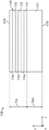
FIG. 14A is a schematic illustration of layer thicknesses as a function of the number of layers of a reflective polarizer;
FIGS. 14B-14C are graphs of layer thickness versus number of layers for a reflective polarizer comprising two interference layer groupings;
FIGS. 15-16 are schematic cross-sectional views of a lens assembly;
FIG. 17 is a schematic representation of the transmittance of a reflective polarizer;
FIG. 18 is a schematic representation of the reflectivity of a reflective polarizer;
FIG. 19 is a schematic of the absorbance of a reflective polarizer; and is
Fig. 20 is a schematic cross-sectional view of an optical element.
Detailed Description
In the following description, reference is made to the accompanying drawings, which form a part hereof and in which is shown by way of illustration various embodiments. The figures are not necessarily to scale. It is to be understood that other embodiments are contemplated and may be made without departing from the scope or spirit of the present description. The following detailed description is, therefore, not to be taken in a limiting sense.
The optical components of the present description include optical films such as reflective polarizer films, reflective polarizer assemblies, lens assemblies, and Polarizing Beam Splitters (PBSs). The optical system of the present specification includes an optical system incorporating the optical member of the present specification. In some cases, the optical system utilizes a folded optic design. In accordance with some embodiments of the present description, it has been found that including a non-adhesive flexible optical layer with a reflective polarizer in an optical stack and/or using a thick multilayer optical film reflective polarizer can allow the reflective polarizer to be bent, for example, to a higher sag diameter ratio and maintain suitable performance without defects during formation. For example, it has been found that optical systems utilizing folded optic designs incorporating the optical stacks or reflective polarizers of the present description and partial reflectors can achieve higher polarization contrast than using conventional optical stacks or reflective polarizers as further described elsewhere herein. As another example, it has been found that optical systems utilizing Polarizing Beam Splitters (PBSs) incorporating the optical stacks or reflective polarizers of the present description provide improved contrast, as well as improved ability to manufacture defect-free PBSs, as compared to optical systems using conventional PBSs.
While reflective polarizer films that are not substantially uniaxially oriented, such as the reflective polarizing brightness enhancement film (DBEF) available from 3M corporation of st paul, MN, usa, can have a total thickness of greater than 100 microns, substantially uniaxially oriented films, such as the Advanced Polarizing Film (APF) available from 3M corporation, are typically much thinner. For example, APF films typically have a thickness of less than about 35 microns. In accordance with the present description, it has been found that thick (e.g., greater than about 50 microns thick) substantially uniaxially-oriented reflective polarizer films provide improved properties when formed, for example, into a curved shape and used in optical systems as further described elsewhere herein. The improved properties include improved mechanical properties and improved optical properties. Improved mechanical properties include improved formability to achieve higher curvature or higher sag diameter ratio without creating defects in the film (e.g., from buckling-induced wrinkles). The improved optical properties include improved polarization contrast when used in optical systems utilizing folded optic designs as further described elsewhere herein. In some cases, the improvement in optical properties is due to the thicker film or optical stack better retaining the desired optical properties of the reflective polarizer film when formed into a curved shape. Alternatively or in addition, the improvement in optical properties may result from the improved reflective polarizer film (prior to formation). For example, reflective polarizer films having reduced block state transmission may be provided by incorporating dichroic dyes into some interference layers and/or including additional interference layers, as further described elsewhere herein.
In addition to or instead of using a thick reflective polarizer film, it has been found that bonding a non-adhesive flexible optical film to a reflective polarizer prior to formation improves physical properties. The thickness of the reflective polarizer may be increased by including additional interference layers within a given thickness range (e.g., by using two interference layer groupings having the same or approximately the same thickness range) and/or by increasing the thickness of the non-interference layers.
In some embodiments, the reflective polarizer includes two or more alternating polymer interference layer groupings to provide high contrast. Such reflective polarizers are further described in U.S. provisional patent application 62/467712(Haag et al), filed on 3/6/2017 and hereby incorporated by reference to the extent not inconsistent with this specification. The term "grouping" is used to refer to a contiguous set of alternating interference layers, absent any spacers or non-interference layers formed within the grouping (e.g., arranged sequentially). In some examples, spacers, non-interference layers, or other layers may be added to the outside of a given stack/packet, forming the outer layer of the film without disrupting the alternating pattern of interference layers in the packet. In some embodiments, the thickness profiles of the interference layers in two different groupings substantially overlap (e.g., both cover the same predetermined wavelength range) in order to increase the contrast ratio of the reflective polarizer. In some embodiments, the reflective polarizer has a contrast ratio (transmission of normally incident light of the pass polarization state divided by transmission of normally incident light of the block polarization state) of at least 100, or at least 200, or at least 500, or at least 1000, or at least 2000. In contrast, conventional multilayer optical film reflective polarizers typically have a contrast ratio of about 50 or less.
Fig. 1 is a schematic cross-sectional view of an optical component 100 comprising: a first optical element 110 having a curved first major surface 111 and an opposing second major surface 112; and an optical stack 120 bonded to and conforming to the curved first major surface 111 of the first optical element 110. In some embodiments, optical stack 120 is bonded to optical element 110 by an optional adhesive layer 132. In some embodiments, optical stack 120 is bonded to optical element 110 as a result of optical element 110 being integrally formed on optical stack 120, for example, by an insert molding process, and optional adhesive layer 132 is omitted. Optical stack 120 includes a first layer 122 and a second layer 126. The first layer 122 has opposing first 123 and second 124 major surfaces and the second layer 126 has opposing first 127 and second 128 major surfaces. In some embodiments, the first layer 122 and the second layer 126 are bonded to each other by an optional adhesive layer 130. In some embodiments, the first layer 122 and the second layer 126 are bonded to each other by being integrally formed with each other, and the optional adhesive layer 130 is omitted.
As used herein, a first element "integrally formed" with a second element means that the first and second elements are manufactured together rather than separately and then joined. Integrally forming includes fabricating a first component and then fabricating a second component on the first component. The reflective polarizer comprising the plurality of layers is integrally formed if the layers are fabricated together (e.g., as a melt stream combination and then cast onto a chill roll to form a cast film with each of the layers and then the cast film is oriented) rather than being fabricated separately and then joined.
Any of the adhesive layers used herein can have an average thickness of from about 1 micron to about 50 microns. The adhesive layer may be or include, for example, one or more of a pressure sensitive adhesive, a hot melt adhesive, a thermosetting adhesive, a solvent based adhesive, and a water based adhesive. In some embodiments, the adhesive layer is substantially index matched to the immediately adjacent layer, as further described elsewhere herein. In some embodiments, the adhesive layer is an optically clear adhesive. Suitable optically clear adhesives include, for example, those available from 3M company (e.g., 3M optically clear adhesives 8171 and 8172, 1 mil and 2 mil thick, respectively) and Norland optical adhesives available from Norland Products inc.
In some embodiments, first layer 122 is a reflective polarizer that substantially transmits light having a first polarization state and substantially reflects light having an orthogonal second polarization state; and the second layer 126 is a non-adhesive flexible optical layer bonded to the reflective polarizer and having first and second substantially parallel and opposing major surfaces 127, 128. In some embodiments, the second layer 126 is a reflective polarizer that substantially transmits light having a first polarization state and substantially reflects light having an orthogonal second polarization state; and first layer 122 is a non-adhesive flexible optical layer bonded to the reflective polarizer and having first 123 and second 124 substantially parallel and opposing major surfaces.
In some embodiments, the second layer 126 is a liner releasably bonded to the first layer 122. A release liner may be applied to the optical film to protect the optical film prior to forming the optical film into a curved shape. One of the release liners may be removed prior to molding a lens or other optical element onto the optical film, and the other release liner may remain to protect the optical film (e.g., so that the mold does not cause scratching or apply a surface texture from the mold onto the optical film). A liner that is bonded to an optical film but can be cleanly removed from the optical film without substantially damaging the optical film can be described as being peelably bonded to the optical film and can be described as a release liner. In some embodiments, a liner releasably bonded to an optical film can be removed from the optical film without causing visible damage to the optical film. A releasably-bonded liner can include a substrate having an adhesive layer that is strongly bonded to the substrate, but weakly bonded to the optical film. For example, the liner may include a thin layer of low tack adhesive applied to a substrate having a surface treated to increase its bonding with the adhesive. Other suitable liners include those that are electrostatically bonded to the optical film as described, for example, in U.S. patent 6,991,695(Tait et al). One example of a suitable gasket is ocet NSA33T available from Sun chemical company (Sun a Kaken Co, Ltd).
The two major surfaces of the non-adhesive flexible optical layer can be described as substantially parallel if they are sufficiently close to parallel that the non-adhesive flexible optical layer has negligible refractive power, or if the slopes at each pair of opposing points on at least 80% of the first and second major surfaces differ by no more than 30 degrees. In some embodiments, the slopes of each pair of opposing points on at least 80%, or at least 85%, or at least 90% of the first major surface and the second major surface differ by no more than 20 degrees, or no more than 10 degrees, or no more than 5 degrees. The opposite point refers to a point along a line in the thickness direction of the non-adhesive flexible optical layer, wherein the line is perpendicular to at least one of the first major surface and the second major surface. In some embodiments, the non-adhesive flexible optical layer has major surfaces that are parallel prior to forming into the desired shape, but after forming, the surfaces are not perfectly parallel due to the thickness variation of the layer caused by the forming.
Within the predetermined wavelength range, the reflective polarizer substantially reflects light having one of orthogonal first and second polarization states (e.g., a first polarization state with an electric field along the x-axis) and substantially transmits light having the other of the first and second polarization states (e.g., a second polarization state with an electric field along the y-axis). A reflective polarizer may be considered to substantially transmit light having a first polarization state within a predetermined wavelength range if at least 60% of the light having the first polarization state and normally incident on the reflective polarizer from one side of the reflective polarizer is transmitted through the reflective polarizer. In some embodiments, at least 70%, or at least 80%, or at least 85% of light having the first polarization state within the predetermined wavelength range is transmitted through the polarizer. The reflective polarizer may be considered to substantially reflect light having the second polarization state within the predetermined wavelength range if at least 60% of the light having the second polarization state in the predetermined wavelength and normally incident on the reflective polarizer from one side of the reflective polarizer is reflected from the reflective polarizer. In some embodiments, at least 70%, or at least 80%, or at least 85% of the light having the second polarization state and the predetermined wavelength is reflected from the polarizer. In some embodiments, the reflective polarizer can include a layer that partially absorbs light having the second polarization state, as further described elsewhere herein.
The predetermined wavelength range may be a wavelength range in which the optical system is designed to operate. For example, the predetermined wavelength range may be a visible light range (400nm to 700 nm). As another example, the predetermined wavelength range may include one or more visible wavelength ranges. For example, the predetermined wavelength range may be a union of more than one narrow wavelength range (e.g., a union of disjoint red, green, and blue wavelength ranges corresponding to the emission color of the display panel). Such wavelength ranges are described in U.S. patent application publication 2017/0068100(Ouderkirk et al), which is hereby incorporated by reference to the extent that it does not contradict the present specification. In some embodiments, the predetermined wavelength range includes other wavelength ranges, such as infrared (e.g., near infrared (about 700nm to about 2500nm)) or ultraviolet (e.g., near ultraviolet (about 300nm to about 400nm)) as well as visible wavelength ranges.
The reflective polarizer used in the optical system of the present description may be any suitable type of reflective polarizer. The reflective polarizer can be a polymeric multilayer optical film such as those described in U.S. Pat. No. 5,882,774(Jonza et al) and U.S. Pat. No. 6,609,795(Weber et al). The reflective polarizer may be substantially uniaxially oriented. A layer in a reflective polarizer or reflective polarizer is substantially uniaxially oriented if the layer is substantially oriented in one in-plane direction and not substantially oriented in an orthogonal in-plane direction and not substantially oriented in a thickness direction. Substantially uniaxially oriented reflective polarizers are available from 3M Company (3M Company) under the trade name Advanced Polarizing Film or APF. Other types of multilayer optical film reflective polarizers (e.g., reflective polarizing brightness enhancement film or DBEF available from 3M company) can also be used. The DBEF film is oriented much more in one in-plane direction than in the orthogonal in-plane direction and also exhibits orientation in the thickness direction. In accordance with "substantially uniaxially oriented" as used herein, the DBEF film is not substantially uniaxially oriented.
In some embodiments, the reflective polarizer is substantially uniaxially oriented prior to forming the curved shape because it has a degree of uniaxiality U of at least 0.7, or at least 0.8, or at least 0.85, where U ═ 1/MDDR-1)/(TDDR 1/2 -1), wherein MDDR is defined as the machine direction stretch ratio and TDDR is defined as the cross direction stretch ratio. Such substantially uniaxially oriented multilayer optical films are described in U.S. Pat. No. 2010/0254002(Merrill et al, supra)So as not to be inconsistent with this specification and hereby incorporated herein), and may include a plurality of alternating first polymer layers and second polymer layers, wherein the first polymer layers have a refractive index that is substantially the same along a length direction (e.g., x-direction) and a thickness direction (e.g., z-direction), but substantially different from a refractive index along a width direction (e.g., y-direction). For example, the absolute value of the difference between the refractive indices in the x-direction and the z-direction may be less than 0.02 or less than 0.01, and the absolute value of the difference between the refractive indices in the x-direction and the y-direction may be greater than 0.05 or greater than 0.10. Unless otherwise indicated, refractive index refers to the refractive index at a wavelength of 550 nm. After forming the curved shape, the reflective polarizer may have at least one layer that is substantially uniaxially oriented in at least one location. In some embodiments, the at least one layer has, at the at least one location, a first refractive index in a first direction along the layer thickness, a second refractive index in a second direction orthogonal to the first direction, and a third refractive index in a third direction orthogonal to the first and second directions, an absolute value of a difference between the first and third refractive indices is less than about 0.02, or less than about 0.01, and an absolute value of a difference between the second and third refractive indices is greater than about 0.05, or greater than about 0.10. In some embodiments, after forming the curved shape, the reflective polarizer has at least one layer that is substantially uniaxially oriented at a plurality of locations.
In accordance with the present description, it has been found that substantially uniaxially oriented reflective polarizer films that are significantly thicker than conventional substantially uniaxially oriented reflective polarizer films provide improved properties when formed into curved shapes and used in optical systems, as further described elsewhere herein. In some embodiments, the reflective polarizer has an average thickness of greater than about 50 microns, or greater than about 60 microns, or greater than about 70 microns.
Suitable materials for the higher index interference layer in the reflective polarizer or mirror film include, for example, polyethylene naphthalate (PEN), copolymers containing PEN and polyester (e.g., polyethylene terephthalate (PET) or dibenzoic acid), glycol-modified polyethylene terephthalate. Suitable materials for the lower index interference layer in the reflective polarizer or mirror film include, for example, PEN-based copolyesters, PET-based copolyesters, Polycarbonates (PCs), or blends of the three types of materials. To achieve high reflectivity with a desired number of layers, adjacent microlayers may, for example, exhibit a refractive index difference of at least 0.2 for light polarized along the block axis.
A non-adhesive flexible optical layer is an optical layer that is not an adhesive that bonds adjacent layers together and is flexible. In some cases, it is convenient to characterize the flexibility of the layer in terms of its bending stiffness, which is defined by D ═ Et (1/12) Et 3 /(1-μ 2 ) Where t is the layer thickness, E is the Young's modulus, and μ is the Poisson's ratio. In some embodiments, the non-adhesive flexible optical layer has a bending stiffness of less than 100N-m, or less than 50N-m, or less than 20N-m, or less than 10N-m, or less than 5N-m, or less than 3N-m, or less than 1N-m, or less than 0.5N-m.
The non-adhesive flexible optical layer may be or include, for example, one or more of a polymer film, an anti-reflective coating, an absorbing polarizer, a neutral density filter, a retarder, a dyed film, an optical filter, a film containing circuitry, an electrode, an infrared-reflective film, a multilayer optical film, and a diffuser. In some embodiments, the non-adhesive flexible optical layer is an optically clear film substrate, such as polyethylene terephthalate (PET), polyethylene naphthalate (PEN), or polymethyl methacrylate (PMMA). A film or adhesive layer may be described as optically clear if it has at least 80% transmission and less than 20% haze for unpolarized normally incident light within a predetermined wavelength range (e.g., 400nm to 700 nm). In some embodiments, the non-adhesive flexible optical layer is an optically clear film having a transmission of at least 85% for unpolarized normally incident light in the wavelength range of 400nm to 700nm and a haze of less than 10%, or less than 5%. In some embodiments, the non-adhesive flexible optical layer is a dyed film and/or an optical filter, and is used to adjust some aspect of transmitted light (e.g., color or intensity). For example, a neutral density filter may be included to reduce the intensity of all visible light transmitted through the filter. The circuit may be used, for example, to control a display element or a touch sensitive element. Electrodes may be included for, for example, darkening the liquid crystal display element. In some embodiments, the non-adhesive flexible optical layer is a release liner as further described elsewhere herein. In some embodiments, the release liner comprises, for example, a PET substrate.
In some embodiments, the first optical element 110 is rigid. For example, the first optical element 110 may be made of a glass material or a polymer material having a thickness sufficient that the first optical element 110 does not significantly bend when a force of 0.5 pounds (2.2 newtons) is applied. In some embodiments, the first optical element 110 is less flexible than the non-adhesive flexible optical layer (one of the first layer 122 and the second layer 126). For example, the first optical element 110 may be rigid, while the non-adhesive flexible optical layer may be a flexible film (e.g., a film that bends or folds when a force of 0.5 pounds is applied).
Fig. 2 is a schematic cross-sectional view of an optical system 201 including a lens assembly 200. Lens assembly 200 may correspond to optical component 100 and includes a first lens 210 and an optical stack 220 disposed on and conforming to a curved major surface of first lens 210. The optical stack 220 includes a first layer 222 and a second layer 226. Optional adhesive layers may be disposed between the first layer 222 and the second layer 226 and/or between the optical stack 220 and the first lens 210. In some implementations, one of the first layer 222 and the second layer 226 is a reflective polarizer and the other of the first layer 222 and the second layer 226 is a non-adhesive flexible optical layer. Optical system 201 also includes retarder 235, retarder 239, and second lens 240 having partial reflector 242 disposed on a major surface of second lens 240. In some embodiments, optical system 201 is adapted to display an image emitted by display 250 to viewing position 265.
In some embodiments, first lens 210 and first optical stack 220 are spaced apart from second lens 240. In some embodiments, first lens 210 is a first optical element having first and second substantially non-parallel major surfaces, and second lens 240 is a second optical element having first and second substantially non-parallel major surfaces. The first and second major surfaces of the lens may be described as being substantially non-parallel if the first and second major surfaces are sufficiently different such that the lens has a non-negligible refractive power, or if the slopes at least one pair of opposing points on the first and second major surfaces differ by at least 10 degrees. In some embodiments, the slopes at least one pair of opposing points on the first major surface and the second major surface differ by at least 20 degrees or at least 30 degrees. The opposite point refers to a point along a straight line in the lens thickness direction, wherein the straight line is perpendicular to one of the first main surface and the second main surface. The first and second major surfaces of the prism may be described as being substantially non-parallel if the angle between the first and second major surfaces is at least about 20 degrees. In some embodiments, the angle between the first and second substantially non-parallel major surfaces of the prism is at least about 30 degrees.
Other configurations of the optical system 201 are possible. In some embodiments, retarder 235 may be disposed on optical stack 220 opposite first lens 210, or may be disposed on second lens 240 opposite partial reflector 242. In some embodiments, retarder 239 may be disposed on partial reflector 242, or may be disposed on display 250. In some embodiments, first lens 210 and second lens 240 are replaced by a single lens (e.g., with partial reflector 242 on one major surface and optical stack 220 on the opposite major surface). In still other embodiments, more than two lenses are included. Other possible arrangements of optical systems are described in U.S. patent application publication 2017/0068100(Ouderkirk et al). Optical stack 220 may be used in place of the reflective polarizer in any of the embodiments described in U.S. patent application publication 2017/0068100(Ouderkirk et al).
In some embodiments, display 250 emits light of the block polarization state of the reflective polarizer, and retarders 235 and 239 are arranged such that light emitted by the display is first incident on the reflective polarizer in the block polarization state. For example, retarders 235 and 239 may have fast axes oriented approximately 90 degrees with respect to each other. Retarders 235 and 239 may be quarter-wave retarders at least one wavelength within a predetermined range of wavelengths. Other configurations are also possible. For example, retarders 235 and 239 may be quarter-wave retarders whose respective fast axes are aligned. In this case, the display 250 may emit light of the pass polarization state of the reflective polarizer such that the light is first incident on the reflective polarizer in the block state.
The retarders 235 and/or 239 may be coatings on a substrate or lens, or may be retarder films, and may be formed of any suitable material, including Linear Photopolymerizable Polymer (LPP) materials and Liquid Crystal Polymer (LCP) materials described, for example, in U.S. patent application publications US2002/0180916(Schadt et al), US 2003/028048(Cherkaoui et al), and US 2005/0072959(Moia et al). Suitable LPP materials include ROP-131EXP 306LPP and suitable LCP materials include ROF-5185EXP 410LCP, both of which are available from Rosic Technologies, Allschwil, Switzerland, Oishulville, Switzerland, Inc. In some embodiments, retarder 235 is a quarter-wave retarder at least one wavelength within a predetermined wavelength range (e.g., 400nm to 700 nm).
The partial reflector 242 may be any suitable partial reflector and may, for example, have an average optical reflectivity of at least 20% or at least 30% over a predetermined wavelength range. For example, a partial reflector may be constructed by coating a thin layer of metal (e.g., silver or aluminum) on a transparent substrate (e.g., a film that may be subsequently adhered to a lens, or the substrate may be a lens). The partial reflector may also be formed by, for example, depositing a thin film dielectric coating onto the surface of the lens substrate, or by depositing a combination of metal and dielectric coatings onto the surface. In some embodiments, the partial reflector has an average optical reflectance and an average optical transmittance at a predetermined wavelength or within a predetermined wavelength range, each of the average optical reflectance and the average optical transmittance being in a range of 20% to 80%, or each of 30% to 70%, or each of 40% to 60%, or each of 45% to 55%. The partial reflector may be, for example, a half mirror. Unless otherwise indicated, average optical reflectance and average optical transmittance within a predetermined wavelength range refer to unweighted averages over the predetermined wavelength range and polarization of optical reflectance and optical transmittance, respectively, determined at normal incidence. In some implementations, the partial reflector can be a reflective polarizer or can have a polarization dependent reflectivity. However, it is generally preferred that the normal incidence optical reflectivity and optical transmission be independent, or substantially independent, of the polarization state of the incident light. Such polarization independence can be obtained using, for example, substantially isotropic metal layers and/or dielectric layers.
In some embodiments, it is preferred that the non-adhesive flexible optical layer have low or high retardation. In embodiments where a non-adhesive flexible optical layer (e.g., layer 226) is disposed between the reflective polarizer (e.g., layer 222) and the partial reflector 242, it is generally preferred that the non-adhesive flexible optical layer have low retardation. In some embodiments, at least one location of the non-adhesive flexible optical layer has an optical retardation of less than about 100nm, or less than about 80nm, or less than about 60nm, or less than about 40nm, or less than about 30nm, or less than about 20nm, or less than about 10nm, or less than about 5 nm. In embodiments where the non-adhesive flexible optical layer (e.g., layer 222) is disposed outside of a region between the reflective polarizer (e.g., layer 226) and the partial reflector 242, it may be preferred that the non-adhesive flexible optical layer have a high retardance. For example, a polyethylene terephthalate (PET) layer may have a high retardation depending on the thickness of the layer and the degree of orientation (e.g., uniaxial or biaxial). In some embodiments, at least one location of the non-adhesive flexible optical layer has an optical retardation of greater than about 200nm, or greater than about 400nm, or greater than about 800nm, or greater than about 1000nm, or greater than about 2000nm, or greater than about 3000nm, or less than about 4000 nm.
The optical retardation at a location of a layer is the phase retardation of light transmitted through the layer normally incident on the layer at that location. The phase retardation is the maximum difference in the phase of two orthogonally polarized rays. The wavelength of the incident light is about 550nm, unless otherwise specified. For example, the delay may vary with position due to common manufacturing variations. In some embodiments, each location of the non-adhesive flexible optical layer has an optical retardation within any range described elsewhere herein.
In some embodiments, each of first lens 210 and second lens 240 has greater than zero diopters in at least one direction. In some embodiments, partial reflector 242 has an average optical reflectance of at least 30% for substantially normal incidence light within a predetermined wavelength range. In some embodiments, the reflective polarizer (one of the first layer 222 and the second layer 226) substantially transmits light having a first polarization state within a predetermined wavelength range and substantially reflects light having an orthogonal second polarization state within the predetermined wavelength range. Optical system 201 has an optical axis 260, which may be understood as an axis along which a light ray 261 propagates through first lens 210, second lens 240, partial reflector 242, and the reflective polarizer without being substantially refracted, along optical axis 260. By substantially non-refracted is meant that the angle between a ray incident on the surface and a ray transmitted through the surface does not exceed 15 degrees. In some embodiments, light rays propagating along optical axis 260 pass through first and second lenses 210, 240, partial reflector 242, and the reflective polarizer while being refracted by no more than 10 degrees, or no more than 5 degrees, or no more than 3 degrees, or no more than 2 degrees at any major surface of optical system 201.
In some embodiments, the optical system 201 is adapted to receive incident light and transmit the light to an observer at an observation location 265. The light exiting the optical system 201 is schematically illustrated by a first light component 255 and a second light component 257.
It has been found that the optical stacks and reflective polarizers of the present description allow optical systems to achieve higher polarization contrast than conventional optical systems. In some embodiments, for an incident light cone of light 253 centered on the optical axis 260 having a second polarization state (a block state for the reflective polarizer) and a wavelength within a predetermined wavelength range and at a full cone angle θ of about 100 degrees to about 160 degrees, the incident light exits the optical system with a first light component 255 having a first polarization state (a pass state for the reflective polarizer) and a second light component 257. In some embodiments, the ratio of the average intensity of the first light component 255 to the average intensity of the second light component 257 is greater than about 100, or greater than about 110, or greater than about 120, or greater than about 130.
Fig. 3 is a schematic cross-sectional view of an optical component 300 that is similar in many respects to optical component 100. Optical component 300 includes a first optical element 310 and an optical stack 320 bonded to and conforming to a curved major surface of first optical element 310. The optical stack 320 includes a first layer 322 and a second layer 326, one of which can be a reflective polarizer and the other can be a non-adhesive flexible optical layer. In some embodiments, first layer 322 and second layer 326 are integrally formed with one another. In other embodiments, an adhesive layer may be used to adhere first layer 322 and second layer 326 to one another. In some embodiments, the first optical element 310 is integrally formed with the optical stack 320, and in other embodiments, the optical stack 320 is adhered to the first optical element 310. The first optical element 310 is thinner at a location 317 remote from the edge 314 of the first optical element 310 (thickness t1) and thicker at another location 319 closer to the edge 314 of the first optical element 310 (thickness t 2). In contrast, in the optical component 100, the first optical element 110 is thicker at a position distant from an edge of the first optical element 110, and is thinner at another position closer to the edge of the first optical element 110.
In some embodiments, the average thickness of the first optical element 310 or other optical elements (e.g., the second optical element or the non-adhesive flexible optical layer) is in a range from about 50 microns to about 500 microns or from about 50 microns to about 100 microns. The average thickness of an element or layer is an unweighted average of the thickness over the total area of the element or layer.
Fig. 4 is a schematic cross-sectional view of an optical system 400 that includes a first optical element 410 and an optical stack 420, which may be, for example, as described for optical component 100. The optical stack 420 includes a first layer 422 and a second layer 426, one of which can be a reflective polarizer and the other can be a non-adhesive flexible optical layer. The first layer 422 and the second layer 426 can be bonded together (e.g., with an optically clear adhesive) and the optical stack can be bonded to the first optical element 410 (e.g., with an optically clear adhesive). The optical system 400 further includes a second optical element 440 adjacent the first optical element 410 and including a first major surface 443 and a second major surface 444 that are substantially non-parallel. In the illustrated embodiment, the first optical element 410 and the second optical element 440 are bonded together by an adhesive layer 434. In other embodiments, the first optical element 410 and the second optical element 440 are spaced apart from each other. This is illustrated in fig. 5, which is a schematic cross-sectional view of an optical system 500. Elements 510, 520, 522, and 526 correspond to elements 410, 420, 422, and 426, respectively. The optical system 500 includes a second optical element 540 disposed adjacent to and spaced apart from the first optical element 510 and having opposing first and second major surfaces 543, 544. In the illustrated embodiment, the second major surface 544 is substantially planar.
In some embodiments, the optical stack is disposed between the first optical element and the second optical element. This is illustrated in fig. 6A, which is a schematic cross-sectional view of optical system 600. Elements 610, 620, 622, and 626 correspond to elements 410, 420, 422, and 426, respectively. Optical system 600 includes a second optical element 640 disposed adjacent to first optical element 610 and having first and second substantially non-parallel major surfaces 643 and 644. The optical stack 620 is disposed between the first optical element 610 and the second optical element 640. In the illustrated embodiment, optical stack 620 is disposed on and conforms to second major surface 644 of second optical element 640. In other embodiments, optical stack 620 may not conform to second major surface 644 and/or second optical element 640 may be spaced apart from optical stack 620. In the illustrated embodiment, optical stack 620 is adhered to a major surface (611 and 644, respectively) of each of first optical element 610 and second optical element 640. In other embodiments, optical stack 620 may be adhered to one of first optical element 610 and second optical element 640 without adhering to the other. In some embodiments, optical stack 620 can be integrally formed with first optical element 610 and/or second optical element 640 via, for example, an insert molding process.
In some embodiments, second optical element 640 is replaced with a second optical layer having substantially parallel and opposing major surfaces. This is illustrated in fig. 6B, which is a schematic cross-sectional view of optical system 600B. Optical system 600b corresponds to optical system 600 except that a second optical layer 640b is used in place of second optical element 640. The optical stack 620b includes first and second layers 622 and 626 and a second optical layer 640 b. In some embodiments, the first layer 622 is a first non-adhesive flexible optical layer, the second layer 626 is a reflective polarizer, and the second optical layer 640b is a second non-adhesive flexible optical layer. Opposing major surfaces 643b and 644b of second optical layer 640b may be substantially parallel.
In some embodiments, the first optical element is a first optical lens and the second optical element (if included) is a second optical lens. In some embodiments, the first optical lens and the second optical lens (if included) may be independently selected from a biconvex lens, a plano-convex lens, a positive meniscus lens, a negative meniscus lens, a plano-concave lens, or a biconcave lens. In other embodiments, the optical element is an optical prism.
Fig. 7 is a schematic cross-sectional view of an optical component 700 that includes a first optical element 710 having a curved first major surface 711 and an optical stack 720 bonded to and conforming to the curved first major surface 711. The optical stack 720 and the first and second optical layers 722, 726 can correspond to the optical stack 120 and the first and second optical layers 722, 726, respectively, and are as described for the optical stack 120 and the first and second optical layers 722, 726. For example, in some implementations, one of the first optical layer 722 and the second optical layer 726 is a reflective polarizer and the other of the first optical layer 722 and the second optical layer 726 is a non-adhesive flexible optical layer. The optical component 700 may be a component in an optical system or may be considered to be the optical system itself. In some embodiments, optical component 700 is a Polarizing Beam Splitter (PBS).
In the illustrated embodiment, first optical element 710 is a first optical prism having a first side 712 and a second side 713 and a hypotenuse side having a first curved major surface 711. The angle α 1 between the first side 712 and the second side 713 may be in a range of about 85 degrees to about 95 degrees. An angle α 2 between the first side 712 and the first curved major surface 711 may be in a range of about 40 degrees to about 50 degrees, and an angle α 3 between the second side 713 and the first curved major surface 711 may be in a range of about 40 degrees to about 50 degrees. In some embodiments, the first optical element 710 has a first side 712 and a second side 713 that are substantially orthogonal, and a hypotenuse side (the side having the first curved major surface 711) that intersects each of the first side 712 and the second side 713 at approximately 45 degrees (e.g., 40 to 50 degrees).
In embodiments where, for example, the first and second major surfaces of the optical element meet at an edge, the angle between the first and second major surfaces of the optical element is the angle between them at the intersection of the two surfaces. In embodiments where the first and second major surfaces do not meet but are separated from each other at an edge of the optical element providing the minor surface of the optical element, the angle between the first and second major surfaces may be defined as the angle between lines tangent to the first and second major surfaces at the edge. This is illustrated in fig. 20, which is a schematic cross-sectional view of an optical element 2010 having a first major surface 2011 and a second major surface 2012. First major surface 2010 and second major surface 2011 form an angle φ between them. In some embodiments, φ is less than about 45 degrees, or less than about 35 degrees. In some embodiments, φ is greater than about 10 degrees, or greater than about 20 degrees.
In some embodiments, an angle in a range of about 20 degrees to about 120 degrees is formed between the first major surface and the second major surface of the optical element. In the case of a prism, this angle may be, for example, about 45 degrees or about 90 degrees, depending on the geometry of the prism and on which side (first major surface) of the prism the optical stack or reflective polarizer is disposed. For an optical lens, the angle may be, for example, about 20 degrees to about 40 degrees.
Fig. 8 is a schematic cross-sectional view of a polarizing beam splitter 800, comprising: a first prism 810 having a first hypotenuse 811; a second prism 840 having a second hypotenuse 844 facing the first hypotenuse 811; and an optical stack 820 disposed between and adhered to first and second oblique sides 811 and 844. The optical stack 820 is adhered to the first oblique side 811 by an adhesive layer 832 and to the second oblique side 844 by an adhesive layer 834. The first layer 822 and the second layer 826 of the optical stack 820 are adhered to each other by an adhesive layer 830. The optical stack 820 may correspond to, for example, the optical stack 120. For example, in some embodiments, the optical stack 820 includes a reflective polarizer (one of the first layer 822 and the second layer 826) that substantially transmits light having a first polarization state and substantially reflects light having an orthogonal second polarization state; and a non-adhesive flexible optical layer (the other of the first layer 822 and the second layer 826) bonded to the reflective polarizer and having first and second substantially parallel and opposing major surfaces. An adhesive layer 830 is disposed between the reflective polarizer and the non-adhesive flexible optical layer and bonds the reflective polarizer to the non-adhesive flexible optical layer.
FIG. 9 is a schematic cross-sectional view of a polarizing beam splitter 900 that is similar in many respects to polarizing beam splitter 800, except that the hypotenuses of first prism 910 and second prism 940 are substantially flat and optical stack 920 is substantially flat. The layers of optical stack 920 may be as described for optical stack 820, except that the layers of optical stack 920 are substantially planar. For example, optical stack 920 may include a reflective polarizer and a non-adhesive flexible optical layer bonded together by an adhesive layer. Optical stack 920 may be bonded to each of first prism 910 and second prism 940 by a respective adhesive layer.
In some embodiments, the optical stack 820 or 920 includes a second non-adhesive flexible optical layer. For example, optical stack 820 or 920 can correspond to optical stack 620b and can include a reflective polarizer disposed between a first non-adhesive flexible optical layer and a second non-adhesive flexible optical layer.
In some embodiments, the polarizing beam splitter comprises a first prism and a second prism, wherein one prism has a curved hypotenuse and the other prism has a substantially flat hypotenuse. In this case, the optical stack may or may not conform to one or both of the oblique sides, and an adhesive layer having a non-uniform thickness may be used to bond the optical stack to the oblique side to which the optical stack does not conform.
Fig. 10 is a schematic cross-sectional view of an optical system 1001 including a lens assembly 1000 and a display panel 1050. Lens assembly 1000 includes a first optical lens 1010 having optical power in at least one direction and having a curved first major surface 1011. Lens assembly 1000 also includes an optical layer 1020 disposed on first major surface 1011. In some embodiments, optical layer 1020 is adhered to and conforms to first major surface 1011. In some embodiments, optical layer 1020 is any optical stack described elsewhere herein. For example, in some embodiments, optical layer 1020 comprises a reflective polarizer that substantially transmits light having a first polarization state and substantially reflects light having an orthogonal second polarization state; and includes a non-adhesive flexible optical layer bonded (e.g., via an adhesive layer) to the reflective polarizer and having first and second substantially parallel and opposing major surfaces. In some embodiments, optical layer 1020 is an integrally formed reflective polarizer comprising a plurality of interference layers, wherein each interference layer reflects or transmits light primarily by optical interference. In some embodiments, the reflective polarizer is adhered to a first major surface 1011 of the first optical lens 1010.
The display panel 1050 emits light 1073 that defines an active area of the first major surface 1011 having a maximum projected dimension D and a corresponding maximum sag S. D is the maximum size of the region of action projected onto a plane at the maximum in the plane and at the maximum size in the plane. S is the maximum sag measured in the direction orthogonal to the plane where the projected dimension is maximized. In the illustrated embodiment, the projected dimension is a maximum in the x-y plane, and S is a maximum along the z-axis. In embodiments where the optical system 1001 has an optical axis, the maximum projected dimension typically occurs when projected onto a plane perpendicular to the optical axis, and the maximum sag typically is along the optical axis. In some embodiments, the S/D is greater than or equal to about 0.03, or greater than or equal to about 0.05, or greater than or equal to about 0.1. In some embodiments, the S/D is not greater than about 0.5.
Fig. 11 is a schematic cross-sectional view of an integrally formed reflective polarizer 1129 that includes a plurality of interference layers 1170 and a non-interference layer 1177. In some embodiments, the plurality of interference layers includes alternating polymer layers 1172 and 1174. In the illustrated embodiment, a single non-interference layer 1177 is included. An interference layer may be described as reflecting or transmitting light primarily by optical interference when the reflectivity and transmissivity of the interference layer can be reasonably accurately described by optical interference or modeled as a result of optical interference. Such interference layers are described, for example, in U.S. Pat. No. 5,882,774(Jonza et al) and U.S. Pat. No. 6,609,795(Weber et al). When adjacent pairs of interference layers having different refractive indices have a combined optical thickness (refractive index multiplied by physical thickness) of 1/2 that is the wavelength of the light, the pair of interference layers reflect the light by optical interference. The interference layer typically has a physical thickness of less than about 200 nanometers. The non-interference layer has an optical thickness too large to reflect visible light via interference. Typically, the non-interference layer has a physical thickness of at least 1 micron. In some embodiments, more than one non-interference layer is included. In some implementations, the plurality of interference layers 1170 are disposed on the same side of the at least one non-interference layer 1177. In some embodiments, at least one non-interference layer (in the illustrated embodiment, non-interference layer 1177) is integrally formed with the plurality of interference layers 1170 and does not primarily reflect or transmit light by optical interference. In some embodiments, the non-interference layer 1177 is a non-adhesive flexible optical layer as further described elsewhere herein. In some embodiments, the reflective polarizer 1129 has a different reflectivity for light in the light blocking state incident from the first major side 1178 than light in the light blocking state incident from the second major side 1179, as further described elsewhere herein.
The average total thickness of the plurality of interference layers 1170 is Tint and the average total thickness of the at least one non-interference layer 1177 is Tnon. In some embodiments, Tint is in the range of about 20 microns to about 70 microns, and Tnon is in the range of about 40 microns to about 100 microns. For example, if the surface of one or more non-interference layers is structured, the total thickness may vary. The overall thickness may also vary due to common manufacturing variations. The average total thickness is an unweighted average of the thickness over the area of the layer. In some embodiments, the reflective polarizer has an average total thickness (Tint + Tnon) of at least 50 microns, or at least 60 microns, or at least 70 microns. In some implementations, the reflective polarizer 1129 is substantially uniaxially oriented. In some embodiments, layer 1172 is substantially uniaxially oriented, e.g., along the x-axis, and layer 1174 is substantially isotropic. In this case, the block polarization state of normally incident light is generally the polarization state of light polarized along the x-axis, and the pass polarization state of normally incident light is generally the polarization state of light polarized along the y-axis.
Fig. 12 is a schematic diagram of an optical film 1229 that includes a plurality of interference layers 1270 and at least one non-interference layer 1277a and 1277b that is integrally formed with the plurality of interference layers 1270. The average total thickness of the at least one non-interference layers 1277a and 1277b is the sum of the thicknesses of the non-interference layers 1277a and 1277 b. The optical film 1229 also includes an adhesive layer 1232 that can be used, for example, to adhere the film to an optical element, such as an optical lens. Optical film 1229 includes at least one non-interference layer on each side of the plurality of interference layers 1270. In some embodiments, for substantially normal incidence light within a predetermined wavelength range, plurality of interference layers 1270 has an average optical transmittance of greater than about 85% for a first polarization state and an average optical reflectance of greater than about 80% for an orthogonal second polarization state.
FIG. 13 is a schematic representation of an optical film 1329 that includes a plurality of interference layers arranged in a first subgroup 1370-1 and a second subgroup 1370-2, and a plurality of non-interference layers 1377a, 1377b, and 1277c integrally formed with the plurality of interference layers. At least one non-interference layer 1377b is disposed between two interference layers 1370a and 1370b of the plurality of interference layers. Optical film 1329 can be a reflective polarizer having an average optical transmittance and an average optical reflectance as further described elsewhere herein. In some embodiments, first sub-set 1370-1 and second sub-set 1370-2 have overlapping thickness distributions.
In some embodiments, optical film 1229 or 1329 is a reflective polarizer that is substantially uniaxially oriented and has an average total thickness (Tint + Tnon) of at least 50 micrometers, or at least 60 micrometers, or at least 70 micrometers.
In some embodiments, the at least one non-adhesive flexible optical layer comprises a non-adhesive flexible optical layer comprising first and second substantially parallel and opposing major surfaces, the non-adhesive flexible optical layer having an optical retardation within any range described elsewhere herein (e.g., less than 100nm or greater than 200 nm).
In some embodiments, the reflective polarizer includes N sequentially numbered layers, wherein each layer has a thickness of less than about 200 nm. For example, the interference layers 1170 may be numbered in this order: the layer immediately adjacent to the non-interference layer 1177 is coded as 1 and the layer immediately adjacent to the first major side 1178 is coded as N. In some embodiments, N is an integer greater than 200 and less than 800. Fig. 14A schematically shows layer thickness 1407 as a function of layer number. Also shown is a fitted curve 1409 having an average slope m. Fitted curve 1409 is the best fit regression of layer thicknesses as a function of layer number applied to the reflective polarizer. In some embodiments, the average slope m of the fitted curve in the region extending from the first layer to the nth layer is less than about 0.2 nm. In some embodiments, the N sequentially numbered layers do not include any non-interference layers, spacer layers, or other optional optical layers that do not form stacks/packets in the reflective polarizer. In some embodiments, the fitted curve 1409 is one or more of a best fit linear regression, a best fit non-linear regression, a best fit polynomial regression, and a best fit exponential regression. In some embodiments, the best fit regression is a linear least squares fit and the average slope is the slope of the linear least squares fit. In some embodiments, an additional layer is included at one end adjacent to layer number 1 and/or at one end adjacent to layer number N. The additional layers may not follow an approximately linear trend from the first layer to the nth layer and are included to provide sharp band edges, as described, for example, in U.S. patent application publication No. 2005/0243425 (Wheatley et al).
In some embodiments, the reflective polarizer includes a plurality of groupings (e.g., groupings 1370-1 and 1370-2), where each grouping has a layer thickness versus layer number that is a substantially continuous curve. Fig. 14B shows the layer thickness versus layer number for a reflective polarizer comprising two packets (packet 1 and packet 2). In some embodiments, the thickness profiles substantially overlap (e.g., greater than 50% of the thickness range of grouping 1 overlaps greater than 50% of the thickness range of grouping 2). In other embodiments, there is little overlap in the thickness ranges. As shown in fig. 14B, the thickness profiles of the two groupings substantially overlap. Fig. 14C shows the layer thickness versus layer number for a reflective polarizer comprising two packets (packet 1 and packet 2) with little or substantially no overlap in the thickness ranges of the two packets. In fig. 14B, the interference layers of the first packet have numbers from 1 to 325, and the interference layers of the second packet have numbers from 326 to 700. In fig. 14C, the interference layer of each of the first and second packets has a number from 1 to 325. In some embodiments, each packet has a layer thickness profile whose fitted curve has an average slope m of less than about 0.2 nm.
In some embodiments, the layer thickness profile may be characterized by a best-fit linear equation applied to the thickness profile of each grouping, where the thickness profile is a function of the number of layers of the sequentially numbered interference layers. In some embodiments, each grouping has a best-fit thickness profile with similar slopes (e.g., within 20% of each other). In some embodiments, the maximum difference between the average slopes of the best-fit linear regression for all packets within the reflective polarizer is less than about 20%. Such reflective polarizers are further described in U.S. provisional patent application 62/467712(Haag et al) filed 3, 6, 2017.
Fig. 15 is a schematic cross-sectional view of a lens assembly 1500 that includes a first optical lens 1510 having a curved first major surface 1511, an optical film 1520 having opposing outermost first major surface 1563 and outermost second major surface 1567, and an adhesive layer 1532 that bonds a first major surface 1523 of the optical film 1520 to the first major surface 1511 of the first optical lens 1510. In some embodiments, the first major surface 1511 of the first optical lens 1510 has undesirable characteristics (e.g., curvature or surface roughness), and the bonding compensates for the undesirable characteristics of the first major surface 1511 of the first optical lens 1510. In some embodiments, optical film 1520 is an optical stack that includes a reflective polarizer and a non-adhesive flexible optical layer bonded to the reflective polarizer, as further described elsewhere herein. In some implementations, the optical film 1520 is or includes an integrally formed reflective polarizer. In some embodiments, the integrally formed reflective polarizer includes multiple interference layers, each of which reflects or transmits light primarily by optical interference.
In some embodiments, the first major surface 1511 of the first optical lens 1510 has undesirable characteristics, including surface curvature. For example, in some embodiments, the curved first major surface 1511 of the first optical lens 1510 has an undesirable curvature of 1/R1, where R1 is the radius of curvature of the first major surface 1511. In some embodiments, the incorporation of optical film 1520 to first major surface 1511 compensates for this undesired curvature because outermost second major surface 1567 of optical film 1520 may have a desired curvature of 1/R2, where R2 is the radius of curvature of outermost second major surface 1567.
FIG. 16 is a schematic cross-sectional view of lens assembly 1600, which includes: a first optical lens 1610 having a curved primary first surface 1611; integrally formed reflective polarizer 1620 comprising a plurality of interference layers, wherein each interference layer reflects or transmits light primarily by optical interference and has opposing first 1663 and second 1667 outermost major surfaces; and an adhesive layer 1632 bonding the first major surface 1623 of the integrally formed reflective polarizer 1620 to the first major surface 1611 of the first optical lens 1610. In the illustrated embodiment, first major surface 1611 of first optical lens 1610 has undesirable characteristics, including average surface roughness. The combination of the integrally formed reflective polarizer 1620 and the first optical lens 1610 compensates for the undesired average surface roughness of the first major surface 1611 of the first optical lens 1610 by providing a desired average surface roughness. In some embodiments, the integrally formed reflective polarizer is replaced with an optical stack described elsewhere herein that includes a reflective polarizer and at least one non-adhesive flexible optical layer bonded to the first optical lens. The outermost major surface of the optical stack opposite the first optical lens can have the properties described herein for second outermost surface 1667.
In some embodiments, the average surface roughness is the roughness parameter Ra, which is the average of the absolute values of the deviations of the surface from an average surface (a smooth surface neglecting surface roughness). In some embodiments, first major surface 1611 has an average surface roughness Ra of greater than about 200nm, or greater than about 150nm, and second outermost surface 1667 has a surface roughness Ra of less than about 100nm, or less than 50 nm. In some embodiments, first major surface 1611 is not optically smooth (e.g., light may scatter due to surface roughness), while second major surface 1667 is optically smooth.
In some embodiments, two or more layers (e.g., two immediately adjacent layers) in a lens assembly or optical stack or optical system are substantially index matched. The substantially index-matched layer has a refractive index such that the absolute value of the difference in refractive indices is less than about 0.20. Unless otherwise indicated, the refractive index is determined at a wavelength of 550 nm.
In some embodiments, the absolute value of the difference between the refractive indices of the first optical lens 1610 and the adhesive layer 1632 is less than about 0.20, or less than about 0.15, or less than about 0.10, or less than about 0.08, or less than about 0.06, or less than about 0.04, or less than about 0.02, or less than about 0.01. In any of the embodiments described herein where the adhesive layer joins the optical stack or reflective polarizer to an optical element, such as a lens or prism, the absolute value of the difference between the refractive indices of the optical element and the adhesive layer can be within any of these ranges.
In some embodiments, an optical film (e.g., optical stack, reflective polarizer) or a plurality of interference layers in an optical film of the present description has an average optical transmission of greater than about 85% for a first polarization state and an average optical reflectance of greater than about 80% for an orthogonal second polarization state. In some embodiments, the average optical transmission is greater than about 85% for a first polarization state of light normally incident on the optical film from one or both sides of the optical film. In some embodiments, the average optical reflectivity is greater than about 80% for the second polarization state of light normally incident on the optical film from one or both sides of the optical film. In some embodiments, the optical film has an average optical absorption for the second polarization state that is greater than about 2%, or 5%, or 10%, such that for substantially normally incident light within a predetermined wavelength range, the optical film has a greater average optical reflectance for light incident from a first major side of the optical film and a lesser average optical reflectance for light incident from an opposite second major side of the optical film. In other embodiments, the average optical absorption is less than about 1% such that the average optical transmittance and the average optical reflectance are about the same from either side of the optical film. For example, referring to fig. 11, some of the interference layers 1170 closer to the non-interference layer 1177 may have a higher absorbance of the second polarization state than layers further from the non-interference layer 1177, such that the optical film has a greater average reflectance for light having the second polarization state incident on the first major side surface 1178 than for light having the second polarization state incident on the second major side surface 1179 due to the higher absorbance of light having the second polarization state incident on the second major side surface 1179.
The difference in average optical reflectivity of light incident on opposite major sides of the optical film may be achieved by including light absorbing molecules in at least some of the plurality of interference layers of the optical film. In some embodiments, the plurality of interference layers comprises a plurality of light absorbing molecules substantially oriented along the second polarization state. In some embodiments, the plurality of light absorbing molecules have an absorption band at least partially within a predetermined wavelength range. The light absorbing molecules may be oriented by including the light absorbing molecules in at least some layers of the film before the film is oriented by stretching (e.g., substantially uniaxially stretching) the film. The light absorbing molecules can then be aligned when the film is stretched. In some embodiments, the plurality of interference layers comprises a plurality of alternating higher index first layers and lower index second layers. For example, layer 1174 may be a higher index layer and layer 1172 may be a lower index layer. In some embodiments, the first layer absorbs substantially more light than the second layer for at least one wavelength within the predetermined range of wavelengths. For example, the absorbance of the first layer may be at least 2 times, or at least 5 times, or at least 10 times the absorbance of the second layer. In some embodiments, the first layer has a substantially higher concentration of light absorbing molecules and the second layer has a substantially lower concentration of light absorbing molecules. Reflective polarizers incorporating light absorbing molecules are described, for example, in U.S. patent application publication 2016/0306086(Haag et al) and U.S. patent 6,096,375(Ouderkirk et al), each of which is incorporated herein by reference to the extent not inconsistent with this specification.
Suitable light absorbing molecules include anthraquinone dyes, azo dyes, and dichroic dyes (e.g., PD-325H, PD-335H, PD-104 and PD-318H) available from Mitsui Fine Chemicals, Japan. The plurality of light absorbing molecules may be a plurality of common types of molecules (e.g., a dichroic dye), or may include a plurality of different types of molecules (e.g., a mixture of dichroic dyes).
FIG. 17 is a schematic representation of the transmittance of a reflective polarizer in its pass and block states for light normally incident on the reflective polarizer from one side of the reflective polarizer. The transmittance may be substantially the same for light normally incident on the reflective polarizer from the other side of the reflective polarizer. The average value of the transmittance at wavelengths within a predetermined wavelength range from λ 1 to λ 2 is Tp in the light transmissive state and Tb in the light blocking state. In some embodiments, λ 1 is about 400nm, and λ 2 is about 700 nm. In some embodiments, Tp is greater than about 80%, or greater than about 85%, or greater than about 90%. In some embodiments, Tb is no more than about 10%, or no more than about 5%, or no more than about 2%, or no more than about 1%, or no more than about 0.5%. In some embodiments, at least one of these conditions is met for Tp and Tb of light incident on one side of the reflective polarizer, and in some embodiments at least one of these conditions is met for Tp and Tb of light incident on each side of the reflective polarizer.
FIG. 18 is a schematic representation of the reflectance of a reflective polarizer in its pass and block states for light normally incident on the reflective polarizer from one side of the reflective polarizer. The reflectivity may be substantially the same for light normally incident on the reflective polarizer from the other side of the reflective polarizer, or may be different, for example, due to the presence of dichroic dyes. The average value of the reflectance at a wavelength within a predetermined wavelength range from λ 1 to λ 2 is Rp in the light transmitting state and Rb in the light blocking state. In some embodiments, Rb is greater than about 75%, or greater than about 80%, or greater than about 85%, or greater than about 90%. In some embodiments, Rp is no more than about 20%, or no more than about 15%, or no more than about 10%, or no more than about 5%. In some embodiments, at least one of these conditions is met for Rp and Rb of light incident on one side of the reflective polarizer, and in some embodiments, at least one of these conditions is met for Rp and Rb of light incident on each side of the reflective polarizer.
FIG. 19 is a schematic representation of the absorbance of a reflective polarizer incorporating a plurality of light absorbing molecules in the pass and block states of the reflective polarizer for light normally incident on the reflective polarizer from one side of the reflective polarizer. For light normally incident on the reflective polarizer from the other side of the reflective polarizer, the absorbance may be different due to the presence of the light absorbing dye. The average value of absorbance at a wavelength within a predetermined wavelength range from λ 1 to λ 2 is Ap in the light transmitting state and Ab in the light blocking state. In some embodiments, Ap is no more than about 3%, or no more than about 2%, or no more than about 1%. In some embodiments, Ab is greater than about 2%, or greater than about 5%, or greater than about 10%. In some embodiments, at least one of these conditions is met for Ap and Ab for light incident on one side of the reflective polarizer, and in some embodiments, at least one of these conditions is met for Ap and Ab for light incident on each side of the reflective polarizer. In some embodiments, the plurality of light absorbing molecules has an absorption band 1904 from λ 3 to λ 4. In some embodiments, the wavelength range from λ 3 to λ 4 is at least partially within a predetermined wavelength range from λ 1 to λ 2. In some embodiments, the wavelength range from λ 3 to λ 4 is entirely within the predetermined wavelength range from λ 1 to λ 2, and in some embodiments, the wavelength range from λ 3 to λ 4 extends to wavelengths less than λ 1 and/or to wavelengths greater than λ 2.
In some embodiments, the optical film has a greater average optical reflectivity for light incident from a first major side of the optical film and a lesser average optical reflectivity for light incident from an opposite second major side of the optical film. In some embodiments, an optical system for displaying an image emitted by a display to a viewing position is provided. The optical system includes the optical film, where a first major side of the optical film faces a display and a second major side of the optical film faces a viewing position. For example, referring to FIG. 2, layer 226 may be a reflective polarizer that has a greater average optical reflectivity for light incident from a first major side of the optical film (the side facing display 250) and a lesser average optical reflectivity for light incident from a second, opposite major side of the optical film (the side facing layer 222). This occurs when dichroic dyes are included in some layers of the optical film, as further described elsewhere herein.
In some embodiments, the reflective polarizer or an optical stack including the reflective polarizer forms a curved shape. In some embodiments, the shaped reflective polarizer or shaped optical stack is bonded to the curved surface of the optical element using an optical adhesive. In other embodiments, the optical element is formed directly onto the shaped reflective polarizer or shaped optical stack by insert molding as generally described, for example, in U.S. patent application publication 2017/0068100(Ouderkirk et al).
The reflective polarizer or optical stack can be shaped via thermoforming, for example, as generally described in U.S. patent application publication 2017/0068100(Ouderkirk et al). Suitable thermoforming Systems include vacuum Forming Systems available from MAAC Machinery Corporation of Karlington, Illinois, IL and press Forming Systems available from Hy-Tech Forming Systems (USA), Inc., Phoenix, AZ, Phoenix, Ehrlich.
Terms such as "about" will be understood by those of ordinary skill in the art in the context of the use and description herein. If the use of "about" in the context of the use and description herein is unclear to one of ordinary skill in the art as applied to quantities expressing feature sizes, quantities, and physical attributes, then "about" will be understood to mean within 10% of the stated value. An amount given as about a specified value may be exactly the specified value. For example, if it is not clear to a person of ordinary skill in the art in the context of the use and description in this specification, an amount having a value of about 1 means that the amount has a value between 0.9 and 1.1, and the value can be 1.
A person of ordinary skill in the art will understand terms such as "substantially" in the context of what is used and described in this specification. If the use of "substantially parallel" is not clear to one of ordinary skill in the art in the context of the use and description in this specification, "substantially parallel" will mean within 30 degrees of parallel. In some embodiments, directions or surfaces that are described as being substantially parallel to each other may be within 20 degrees, or within 10 degrees of parallel, or may be parallel or nominally parallel. If the use of "substantially vertical" is not clear to one of ordinary skill in the art in the context of the use and description in this specification, "substantially vertical" will mean within 30 degrees of normal. In some embodiments, a direction described as substantially perpendicular may be within 20 degrees or within 10 degrees of normal, or may be normal or a nominal normal.
The following is a list of exemplary embodiments of the present specification.
Embodiment 1 is an optical system, comprising:
a first optical element comprising a curved first major surface; and
an optical stack bonded to and conforming to the curved first major surface of the first optical element, and comprising:
a reflective polarizer substantially transmitting light having a first polarization state and substantially reflecting light having an orthogonal second polarization state; and
a non-adhesive flexible optical layer bonded to the reflective polarizer and comprising first and second substantially parallel and opposing major surfaces, at least one location on the non-adhesive flexible optical layer having an optical retardation of less than about 100nm or greater than about 200nm at a wavelength of about 550 nm.
Embodiment 2 is the optical system of embodiment 1, wherein the first optical element further comprises a second major surface, an angle in a range of about 20 degrees to about 120 degrees being formed between the first major surface and the second major surface of the first optical element.
Embodiment 3 is the optical system of embodiment 1, wherein the first optical element comprises a first optical lens having optical power in two mutually orthogonal directions.
Embodiment 4 is the optical system of embodiment 1, wherein the first optical element comprises a first optical prism.
Embodiment 5 is the optical system of embodiment 1, further comprising a second optical element adjacent to the first optical element and comprising first and second major surfaces that are substantially non-parallel.
Embodiment 6 is the optical system of embodiment 1, wherein the reflective polarizer comprises N sequentially numbered layers, N being an integer greater than 200 and less than 800, each layer having an average thickness less than about 200nm, the fitted curve being a best fit regression of the layer thicknesses as a function of the number of layers applied to the reflective polarizer, the fitted curve having an average slope in a region extending from the first layer to the nth layer of less than about 0.2 nm.
Embodiment 7 is the optical system of embodiment 1, wherein the optical retardation is less than about 80nm, or less than about 60nm, or less than about 40nm, or less than about 30nm, or less than about 20nm, or less than about 10nm, or less than about 5 nm.
Embodiment 8 is the optical system of embodiment 1, wherein the optical retardation is greater than about 400nm, or greater than about 800nm, or greater than about 1000nm, or greater than about 2000nm, or greater than about 3000nm, or greater than about 4000 nm.
Embodiment 9 is the optical system of embodiment 1, wherein the non-adhesive flexible optical layer comprises one or more of a polymer film, an anti-reflective coating, an absorbing polarizer, a neutral density filter, a retarder, a dyed film, an optical filter, a film comprising an electrical circuit, an electrode, an infrared reflective film, a multilayer optical film, and a diffuser.
Embodiment 11 is the optical system of embodiment 1, wherein the reflective polarizer is a polymeric multilayer optical film comprising:
a plurality of interference layers, each interference layer reflecting or transmitting light primarily by optical interference, the plurality of interference layers having an average total thickness of about 20 microns to about 70 microns; and
at least one non-interference layer integrally formed with the plurality of interference layers and that does not primarily reflect or transmit light by optical interference, the at least one non-interference layer having an average total thickness of about 40 microns to about 100 microns such that the plurality of interference layers has an average optical transmittance for a first polarization state of greater than about 85% and an average optical reflectance for a second polarization state of greater than about 80% for substantially normally incident light within a predetermined wavelength range.
Embodiment 12 is a Polarizing Beam Splitter (PBS), comprising:
a first prism including a first hypotenuse;
a second prism including a second hypotenuse facing the first hypotenuse; and
an optical stack disposed between and adhered to the first and second oblique edges, the optical stack comprising:
a reflective polarizer substantially transmitting light having a first polarization state and substantially reflecting light having an orthogonal second polarization state;
a non-adhesive flexible optical layer bonded to the reflective polarizer and comprising first and second substantially parallel and opposing major surfaces, at least one location on the non-adhesive flexible optical layer having an optical retardation of less than about 100nm or greater than about 200 nm; and
an adhesive layer disposed between the reflective polarizer and the non-adhesive flexible optical layer and bonding the reflective polarizer to the non-adhesive flexible optical layer.
Embodiment 13 is the PBS of embodiment 12, wherein at least one of the first oblique side and the second oblique side is curved.
Embodiment 14 is the PBS of embodiment 12, wherein the reflective polarizer comprises a plurality of interference layers, each interference layer reflecting or transmitting light primarily by optical interference.
Embodiment 15 is the PBS of embodiment 12, wherein the reflective polarizer comprises N sequentially numbered layers, N being an integer greater than 200 and less than 800, each layer having an average thickness less than about 200nm, the fitted curve being a best fit regression of the layer thicknesses as a function of the number of layers applied to the reflective polarizer, the fitted curve having an average slope in a region extending from the first layer to the nth layer of less than about 0.2 nm.
Embodiment 16 is the PBS of embodiment 12, wherein the reflective polarizer is a polymeric multilayer optical film comprising:
a plurality of interference layers, each interference layer reflecting or transmitting light primarily by optical interference, the plurality of interference layers having an average total thickness of about 20 microns to about 70 microns; and
at least one non-interference layer integrally formed with the plurality of interference layers and that does not primarily reflect or transmit light by optical interference, the at least one non-interference layer having an average total thickness of about 40 microns to about 100 microns such that the plurality of interference layers has an average optical transmittance for a first polarization state of greater than about 85% and an average optical reflectance for a second polarization state of greater than about 80% for substantially normally incident light within a predetermined wavelength range.
Embodiment 17 is a lens assembly, comprising:
a first optical lens having diopter in at least one direction;
and
an optical stack adhered to the first optical lens and comprising:
a reflective polarizer substantially transmitting light having a first polarization state and substantially reflecting light having an orthogonal second polarization state;
a non-adhesive flexible optical layer bonded to the reflective polarizer and comprising first and second substantially parallel and opposing major surfaces, at least one location on the non-adhesive flexible optical layer having an optical retardation of less than about 100nm or greater than about 200 nm; and
an adhesive layer disposed between the reflective polarizer and the non-adhesive flexible optical layer and bonding the reflective polarizer to the non-adhesive flexible optical layer.
Embodiment 18 is the lens assembly of embodiment 17, wherein the non-adhesive flexible optical layer comprises one or more of a polymer film, an anti-reflective coating, an absorbing polarizer, a neutral density filter, a retarder, a dyed film, an optical filter, a film comprising an electrical circuit, an electrode, an infrared-reflective film, a multilayer optical film, and a diffuser.
Embodiment 19 is the lens assembly of embodiment 17, wherein the non-adhesive flexible optical layer is a release liner.
a plurality of interference layers, each interference layer reflecting or transmitting light primarily by optical interference, the plurality of interference layers having an average total thickness of about 20 microns to about 70 microns; and
at least one non-interference layer integrally formed with the plurality of interference layers and that does not primarily reflect or transmit light by optical interference, the at least one non-interference layer having an average total thickness of about 40 microns to about 100 microns such that the plurality of interference layers has an average optical transmittance for a first polarization state of greater than about 85% and an average optical reflectance for a second polarization state of greater than about 80% for substantially normally incident light within a predetermined wavelength range.
a first optical lens having optical power in at least one direction and comprising a curved first major surface; and
an integrally formed reflective polarizer comprising a plurality of interference layers, each interference layer reflecting or transmitting light primarily by optical interference, at least one interference layer being substantially uniaxially oriented in at least one location, the reflective polarizer adhered to the first major surface of the first optical lens, the reflective polarizer substantially transmitting light having a first polarization state and substantially reflecting light having an orthogonal second polarization state,
wherein the first main surface comprises an active area with a maximum projected dimension D and a corresponding maximum sag S, S/D ≥ 0.03; and is
The reflective polarizer has an average thickness greater than about 50 microns.
a plurality of interference layers, each interference layer reflecting or transmitting light primarily by optical interference, the plurality of interference layers having an average total thickness of about 20 microns to about 70 microns; and
at least one non-interference layer integrally formed with the plurality of interference layers and that does not primarily reflect or transmit light by optical interference, the at least one non-interference layer having an average total thickness of about 40 microns to about 100 microns such that for substantially normally incident light within a predetermined wavelength range, the plurality of interference layers have an average optical transmission of greater than about 85% for a first polarization state and an average optical reflection of greater than about 80% for an orthogonal second polarization state.
Embodiment 25 is the optical film of embodiment 24, wherein at least one non-interference layer comprises a non-adhesive flexible optical layer having first and second substantially parallel and opposing major surfaces, at least one location on the non-adhesive flexible optical layer having an optical retardation of less than about 100nm or greater than about 200 nm.
Embodiment 26 is the optical film of embodiment 24, the optical film having an average optical absorption greater than about 2% for substantially normally incident light having the second polarization state over a predetermined wavelength range, such that for substantially normally incident light over the predetermined wavelength range, the optical film has a greater average optical reflectance for light incident from a first major side of the optical film and a lesser average optical reflectance for light incident from an opposite second major side of the optical film.
Embodiment 27 is a reflective polarizer assembly, comprising:
an integrally formed reflective polarizer having an average thickness greater than about 50 microns and comprising a plurality of interference layers, each interference layer reflecting or transmitting light primarily by optical interference, at least one interference layer being substantially uniaxially oriented in at least one location, the integrally formed reflective polarizer comprising an outermost curved major surface; and
an optical element formed directly on and conforming to the outermost curved major surface of the reflective polarizer.
Embodiment 28 is the reflective polarizer assembly of embodiment 27, wherein the integrally formed reflective polarizer further comprises at least one non-interference layer integrally formed with the plurality of interference layers and that does not primarily reflect or transmit light by optical interference, the at least one non-interference layer having an average total thickness of about 40 microns to about 100 microns, the plurality of interference layers having an average total thickness of about 20 microns to about 70 microns.
Embodiment 29 is the reflective polarizer assembly of embodiment 27, wherein the plurality of interference layers have an average optical transmittance for a first polarization state of greater than about 85%, an average optical reflectance for an orthogonal second polarization state of greater than about 80%, and an average optical absorptance for the second polarization state for substantially normally incident light within the predetermined wavelength range, such that the integrally formed reflective polarizer has a greater average optical reflectance for light incident from a first major side of the reflective polarizer and a lesser average optical reflectance for light incident from an opposite second major side of the reflective polarizer for substantially normally incident light within the predetermined wavelength range.
Embodiment 30 is a lens assembly comprising:
a first optical lens having optical power in at least one direction and having a curved first major surface having an undesirable characteristic;
an integrally formed reflective polarizer comprising a plurality of interference layers, each interference layer reflecting or transmitting light primarily by optical interference, the integrally formed reflective polarizer comprising opposing first and second outermost major surfaces; and
an adhesive layer bonding the first major surface of the integrally formed reflective polarizer to the first major surface of the first optical lens, the bonding compensating for the undesirable characteristic of the first major surface of the first optical lens, the second outermost surface of the integrally formed reflective polarizer having the desirable characteristic.
Embodiment 31 is the lens assembly of embodiment 30, wherein the undesirable characteristic includes surface curvature, the curved first major surface of the first optical lens has the undesirable curvature, and the second outermost surface of the integrally formed reflective polarizer has the desirable curvature.
Embodiment 32 is the lens assembly of embodiment 30, wherein the undesirable characteristic includes an average surface roughness, the curved first major surface has an undesirable average surface roughness, and the second outermost surface of the integrally formed reflective polarizer has a desirable average surface roughness.
Embodiment 33 is the lens assembly of embodiment 32, wherein the second outermost surface is optically smooth, but the curved first major surface is not optically smooth.
Embodiment 34 is an optical system, comprising:
at least one lens having a diopter greater than zero in at least one direction;
a partial reflector having an average optical reflectivity of at least 30% for substantially normally incident light within a predetermined wavelength range; and
a reflective polarizer substantially transmitting light having a first polarization state within a predetermined wavelength range and substantially reflecting light having an orthogonal second polarization state within the predetermined wavelength range, the optical system having an optical axis, the light rays propagating along the optical axis passing through the at least one lens, the partial reflector and the reflective polarizer substantially without being refracted such that for an incident cone of light centered on the optical axis having the second polarization state and a wavelength within the predetermined wavelength range and at a full cone angle of about 100 degrees to about 160 degrees, the incident light exits the optical system, the exiting light having a first light component and a second light component, the first light component having the first polarization state and the second light component having the second polarization state, a ratio of an average intensity of the first light component to an average intensity of the second light component being greater than about 100.
Embodiment 35 is the optical system of embodiment 34, wherein an optical stack comprises the reflective polarizer and a non-adhesive flexible optical layer bonded to the reflective polarizer.
Embodiment 36 is the optical system of embodiment 35, wherein the at least one lens comprises a first lens comprising a curved first major surface, the optical stack being bonded to and conforming to the curved first major surface.
Embodiment 37 is the optical system of embodiment 34, wherein the reflective polarizer is a polymeric multilayer optical film comprising:
a plurality of interference layers, each interference layer reflecting or transmitting light primarily by optical interference, the plurality of interference layers having an average total thickness of about 20 microns to about 70 microns; and
at least one non-interference layer integrally formed with the plurality of interference layers and that does not primarily reflect or transmit light by optical interference, the at least one non-interference layer having an average total thickness of about 40 microns to about 100 microns such that the plurality of interference layers has an average optical transmittance for a first polarization state of greater than about 85% and an average optical reflectance for a second polarization state of greater than about 80% for substantially normally incident light within a predetermined wavelength range.
Embodiment 38 is the optical system of embodiment 34, wherein the reflective polarizer is integrally formed and includes a plurality of interference layers each reflecting or transmitting light primarily by optical interference, the reflective polarizer adhered to the curved first major surface, the curved first major surface including an active area having a maximum projected dimension D and a corresponding maximum sag S, S/D ≧ 0.03.
Embodiment 39 is the optical system of embodiment 34, wherein the reflective polarizer has an average thickness of greater than about 50 microns.
Examples
Reflective polarizer 1
Birefringent reflective polarizer optical films were prepared as follows. Two multi-layer light packets were coextruded, where each packet comprised 325 alternating layers of polyethylene naphthalate (PEN) and one low index isotropic layer comprised of a blend of polycarbonate and copolyester (PC: coPET) such that the refractive index was about 1.57 and remained substantially isotropic when uniaxially oriented, with a PC: coPET molar ratio of about 42.5 mole% PC and 57.5 mole% coPET, and a Tg of 105 degrees celsius. Such an isotropic material is selected such that after stretching its refractive indices in the two non-stretched directions remain substantially matched to the refractive indices of the birefringent material in the non-stretched direction, while in the stretched direction the refractive indices between the birefringent layer and the non-birefringent layer are substantially mismatched. PEN and PC coPET polymers were fed from separate extruders to a multilayer coextrusion feedblock where the polymers were assembled into packets of 325 alternating optical layers ("packet 1" and "packet 2") plus a thicker PC/coPET protective boundary layer on the outside of the stacked optical packets, for a total of 652 layers. The film is stretched substantially uniaxially in a parabolic tenter frame as described in U.S. patent 6,916,440(Jackson et al). The film was drawn to a draw ratio of about 6 at a temperature of about 150 ℃.
This layer thickness profile of the reflective polarizer 1 is shown in fig. 14B, where groupings 1 and 2 are indicated. Using least squares linear regression, the average slope of packet 1 was about 0.17 nm/layer and the average slope of packet 2 was about 0.18 nm/layer, thus exhibiting a corresponding slope difference of about 6% for both packets. The reflective polarizer 1 had a resulting total thickness of about 63.2 μm as measured by a capacitance gauge, a transmission of 90% in the clear state, and a transmission of 0.015% in the block state. The total thickness of the interference layers is 54.2 microns, the non-interference layers including the outermost layers (e.g., corresponding to non-interference layers 1377a and 1377c) have thicknesses of 2.2 microns and 3.5 microns, respectively, and the inner spacer layer (e.g., corresponding to non-interference layer 1377b) has a thickness of 3.3 microns.
Example 1
The reflective polarizer 1 was laminated to a 75 micron thick Polymethylmethacrylate (PMMA) film using a 1 mil thick 3M 8171 optically clear adhesive available from 3M Company, st. paul, MN, st. The resulting laminate was thermoformed into a curved shape having a sag diameter ratio of 0.026 using a vacuum forming process. The lens is formed onto the laminate by injection molding optical grade acrylic onto the laminate in an insert molding process. Thermoforming and injection molding were performed as described in U.S. patent application publication 2017/0068100(Ouderkirk et al). No wrinkling of the laminate was observed during the forming process.
Example 2
The reflective polarizer 1 was laminated to a 75 micron thick Polymethylmethacrylate (PMMA) film using a 1 mil thick 3M 8171 optically clear adhesive available from 3M Company, st. paul, MN, st. The resulting laminate was thermoformed into a curved shape having a sag diameter ratio of 0.13 using a vacuum forming process. The lens is formed onto the laminate by injection molding optical grade acrylic onto the laminate in an insert molding process. Thermoforming and injection molding were performed as described in U.S. patent application publication 2017/0068100(Ouderkirk et al). No wrinkles of the laminate were observed during the forming process.
Example 3
The reflective polarizer 1 was laminated between two 75 micron thick Polymethylmethacrylate (PMMA) films using a 1 mil thick 3M 8171 optically clear adhesive (available from 3M Company, st. paul, MN, st.) available from 3M Company of saint paul, minnesota. The resulting laminate was thermoformed into a curved shape having a sag diameter ratio of 0.026 using a vacuum forming process. The laminate of example 3 maintained its desired shape to better tolerances than the laminate of example 1. The lens is formed onto the laminate by injection molding optical grade acrylic onto the laminate in an insert molding process. Thermoforming and injection molding were performed as described in U.S. patent application publication 2017/0068100(Ouderkirk et al). No wrinkles of the laminate were observed during the forming process.
Example 4
The reflective polarizer 1 was laminated between two 75 micron thick Polymethylmethacrylate (PMMA) films using a 1 mil thick 3M 8171 optically clear adhesive (available from 3M Company, st. paul, MN, st.) available from 3M Company of saint paul, minnesota. The resulting laminate was thermoformed into a curved shape having a sag diameter ratio of 0.13 using a vacuum forming process. The laminate of example 4 maintained its desired shape to better tolerances than the laminate of example 2. The lens is formed onto the laminate by injection molding optical grade acrylic onto the laminate in an insert molding process. Thermoforming and injection molding were performed as described in U.S. patent application publication 2017/0068100(Ouderkirk et al). No wrinkles of the laminate were observed during the forming process.
Unless otherwise indicated, descriptions with respect to elements in the figures should be understood to apply equally to corresponding elements in other figures. Although specific embodiments have been illustrated and described herein, it will be appreciated by those of ordinary skill in the art that a variety of alternate and/or equivalent implementations may be substituted for the specific embodiments shown and described without departing from the scope of the present disclosure. This application is intended to cover any adaptations or variations of the specific embodiments discussed herein. Accordingly, the disclosure is intended to be limited only by the claims and the equivalents thereof.
Claims (9)
1. An optical system, comprising:
a first optical element comprising a curved first major surface; and
an optical stack bonded to and conforming by deformation to the curved first major surface of the first optical element, and comprising:
a reflective polarizer substantially transmitting light having a first polarization state and substantially reflecting light having an orthogonal second polarization state, the reflective polarizer being substantially uniaxially oriented prior to being deformed; and
a non-adhesive flexible optical layer bonded to the reflective polarizer, the non-adhesive flexible optical layer having a bending stiffness less than that of the first optical element and comprising first and second substantially parallel and opposing major surfaces prior to deformation and first and second substantially non-parallel and opposing major surfaces after deformation, wherein substantially parallel means that slopes at each pair of opposing points on at least 80% of the first and second major surfaces differ by no more than 5 degrees and substantially non-parallel means that slopes at least one pair of opposing points on the first and second major surfaces differ by more than 5 degrees, the opposing points being points along a straight line in the thickness direction of the non-adhesive flexible optical layer, wherein the line is perpendicular to at least one of the first major surface and the second major surface, and wherein at least one location on the non-adhesive flexible optical layer has an optical retardation of greater than 400nm at a wavelength of 550 nm.
2. The optical system of claim 1, wherein the first optical element comprises a first optical lens having optical power in two mutually orthogonal directions.
3. The optical system of claim 1, wherein the first optical element comprises a first optical prism.
4. The optical system of claim 1, wherein the reflective polarizer comprises N sequentially numbered layers, N being an integer greater than 200 and less than 800, each layer having an average thickness less than 200nm, a fitted curve being a best fit regression of layer thicknesses as a function of number of layers applied to the reflective polarizer, the fitted curve having an average slope in a region extending from a first layer to an nth layer of less than 0.2 nm.
5. The optical system of claim 1, wherein the reflective polarizer is a polymeric multilayer optical film comprising:
a plurality of interference layers, each interference layer reflecting or transmitting light primarily by optical interference, an average total thickness of the plurality of interference layers being 20 to 70 microns; and
at least one non-interference layer integrally formed with the plurality of interference layers and that does not primarily reflect or transmit light by optical interference, the at least one non-interference layer having an average total thickness of 40 to 100 microns such that for substantially normal incidence light within a predetermined wavelength range the plurality of interference layers have an average optical transmission of greater than 85% for the first polarization state and an average optical reflection of greater than 80% for the second polarization state.
6. A Polarizing Beam Splitter (PBS), comprising:
a first prism comprising a curved first hypotenuse;
a second prism including a curved second hypotenuse facing the curved first hypotenuse; and
an optical stack disposed between, adhered to, and conforming to by deformation the curved first and second oblique sides, the optical stack comprising:
a reflective polarizer substantially transmitting light having a first polarization state and substantially reflecting light having an orthogonal second polarization state, the reflective polarizer being substantially uniaxially oriented prior to deformation;
a non-adhesive flexible optical layer bonded to the reflective polarizer, the non-adhesive flexible optical layer having a bending stiffness less than the bending stiffness of the first and second prisms, and the non-adhesive flexible optical layer comprising first and second substantially parallel and opposing major surfaces prior to deformation and first and second substantially non-parallel and opposing major surfaces after deformation, wherein substantially parallel means that slopes at each pair of opposing points on at least 80% of the first and second major surfaces differ by no more than 5 degrees, substantially non-parallel means that slopes at least one pair of opposing points on the first and second major surfaces differ by more than 5 degrees, the opposing points being points along a straight line in a thickness direction of the non-adhesive flexible optical layer, wherein the line is perpendicular to at least one of the first major surface and the second major surface, and wherein at least one location on the non-adhesive flexible optical layer has an optical retardation of less than 100nm or greater than 400 nm; and
an adhesive layer disposed between the reflective polarizer and the non-adhesive flexible optical layer and bonding the reflective polarizer to the non-adhesive flexible optical layer.
7. The PBS of claim 6, wherein the reflective polarizer comprises N sequentially numbered layers, N being an integer greater than 200 and less than 800, each layer having an average thickness less than 200nm, a fitted curve being a best-fit regression of layer thicknesses as a function of number of layers applied to the reflective polarizer, the fitted curve having an average slope in a region extending from a first layer to an nth layer of less than 0.2 nm.
8. The PBS of claim 6, wherein the reflective polarizer is a polymeric multilayer optical film comprising:
a plurality of interference layers, each interference layer reflecting or transmitting light primarily by optical interference, an average total thickness of the plurality of interference layers being 20 to 70 microns; and
at least one non-interference layer integrally formed with the plurality of interference layers and that does not primarily reflect or transmit light by optical interference, the at least one non-interference layer having an average total thickness of 40 to 100 microns such that for substantially normally incident light within a predetermined wavelength range the plurality of interference layers have an average optical transmission of greater than 85% for the first polarization state and an average optical reflection of greater than 80% for the second polarization state.
9. A lens assembly, comprising:
a first optical lens comprising a curved first major surface and having optical power in at least one direction; and
an optical stack adhered to the first optical lens and conforming to the curved first major surface of the first optical lens by deformation, and comprising:
a reflective polarizer substantially transmitting light having a first polarization state and substantially reflecting light having an orthogonal second polarization state, the reflective polarizer being substantially uniaxially oriented prior to deformation;
a non-adhesive flexible optical layer bonded to the reflective polarizer, the non-adhesive flexible optical layer having a bending stiffness less than a bending stiffness of the first optical lens, and the non-adhesive flexible optical layer comprising first and second substantially parallel and opposing major surfaces prior to deformation and first and second substantially non-parallel and opposing major surfaces after deformation, wherein substantially parallel means that slopes at each pair of opposing points on at least 80% of the first and second major surfaces differ by no more than 5 degrees, substantially non-parallel means that slopes at least one pair of opposing points on the first and second major surfaces differ by more than 5 degrees, the opposing points being points along a line in the thickness direction of the non-adhesive flexible optical layer, wherein the line is perpendicular to at least one of the first major surface and the second major surface, and wherein at least one location on the non-adhesive flexible optical layer has an optical retardation of less than 100nm or greater than 400 nm; and
an adhesive layer disposed between the reflective polarizer and the non-adhesive flexible optical layer and bonding the reflective polarizer to the non-adhesive flexible optical layer.
Applications Claiming Priority (5)
| Application Number | Priority Date | Filing Date | Title |
|---|---|---|---|
| US201762569942P | 2017-10-09 | 2017-10-09 | |
| US62/569,942 | 2017-10-09 | ||
| US201762577203P | 2017-10-26 | 2017-10-26 | |
| US62/577,203 | 2017-10-26 | ||
| PCT/IB2018/057570 WO2019073330A2 (en) | 2017-10-09 | 2018-09-28 | Optical components and optical systems |
Publications (2)
| Publication Number | Publication Date |
|---|---|
| CN111344613A CN111344613A (en) | 2020-06-26 |
| CN111344613B true CN111344613B (en) | 2022-09-27 |
Family
ID=63965709
Family Applications (1)
| Application Number | Title | Priority Date | Filing Date |
|---|---|---|---|
| CN201880072995.9A Active CN111344613B (en) | 2017-10-09 | 2018-09-28 | Optical component and optical system |
Country Status (6)
| Country | Link |
|---|---|
| US (1) | US20200319388A1 (en) |
| JP (2) | JP2020537194A (en) |
| KR (1) | KR20200066672A (en) |
| CN (1) | CN111344613B (en) |
| TW (1) | TW201928404A (en) |
| WO (1) | WO2019073330A2 (en) |
Families Citing this family (12)
| Publication number | Priority date | Publication date | Assignee | Title |
|---|---|---|---|---|
| CN111316146B (en) | 2017-10-10 | 2022-06-03 | 3M创新有限公司 | Curved reflective polarizing film and method of forming the same |
| JP7326287B2 (en) | 2017-12-20 | 2023-08-15 | スリーエム イノベイティブ プロパティズ カンパニー | Optical Stacks and Polarizing Beamsplitters |
| JP2021514074A (en) * | 2018-02-19 | 2021-06-03 | スリーエム イノベイティブ プロパティズ カンパニー | Optical film device |
| US11327381B2 (en) * | 2018-03-23 | 2022-05-10 | National Institute Of Advanced Industrial Science And Technology | Light beam switching element, assembly of same, and control method for same |
| CN110208951A (en) * | 2019-07-19 | 2019-09-06 | 业成科技(成都)有限公司 | Wear the thin light optical system of virtual reality display device |
| KR102496849B1 (en) * | 2019-12-27 | 2023-02-07 | 한국광기술원 | Augmented Reality Optical Device and System with Minimized Exposure of Augmented Reality Image |
| US20240012179A1 (en) * | 2020-12-11 | 2024-01-11 | 3M Innovative Properties Company | Optical Lens Including Optical Film Bonded to Lens Substrate |
| WO2022136974A1 (en) * | 2020-12-21 | 2022-06-30 | 3M Innovative Properties Company | Reflective polarizer |
| CN116745658A (en) * | 2020-12-14 | 2023-09-12 | 3M创新有限公司 | Optical system |
| WO2022200904A1 (en) * | 2021-03-26 | 2022-09-29 | 3M Innovative Properties Company | Optical film and optical system |
| WO2023157947A1 (en) * | 2022-02-18 | 2023-08-24 | 富士フイルム株式会社 | Optical laminate, optical lens, virtual reality display device, optical anisotropic film, shaped body, reflective circular polarizer, non-planar reflective circular polarizer, laminated optical body, and composite lens |
| WO2024009267A1 (en) * | 2022-07-08 | 2024-01-11 | Hypervision Ltd | Apparatus, and system of an optical lens |
Citations (5)
| Publication number | Priority date | Publication date | Assignee | Title |
|---|---|---|---|---|
| US6075651A (en) * | 1999-01-28 | 2000-06-13 | Kaiser Electro-Optics, Inc. | Compact collimating apparatus |
| CN102016659A (en) * | 2008-03-31 | 2011-04-13 | 3M创新有限公司 | Low layer count reflective polarizer with optimized gain |
| US8817371B1 (en) * | 2008-08-01 | 2014-08-26 | Simon Andrew Boothroyd | Polarizing beam splitters |
| CN106062597A (en) * | 2014-03-19 | 2016-10-26 | 帝人株式会社 | Reflective polarizing film for liquid-crystal-display polarizer, liquid-crystal-display polarizer comprising same, liquid-crystal-display optical element, and liquid-crystal display |
| US9581827B1 (en) * | 2015-09-03 | 2017-02-28 | 3M Innovative Properties Company | Optical system |
Family Cites Families (28)
| Publication number | Priority date | Publication date | Assignee | Title |
|---|---|---|---|---|
| US6160597A (en) | 1993-02-17 | 2000-12-12 | Rolic Ag | Optical component and method of manufacture |
| US5882774A (en) | 1993-12-21 | 1999-03-16 | Minnesota Mining And Manufacturing Company | Optical film |
| US6096375A (en) | 1993-12-21 | 2000-08-01 | 3M Innovative Properties Company | Optical polarizer |
| US6080467A (en) * | 1995-06-26 | 2000-06-27 | 3M Innovative Properties Company | High efficiency optical devices |
| US6531230B1 (en) * | 1998-01-13 | 2003-03-11 | 3M Innovative Properties Company | Color shifting film |
| US6157490A (en) | 1998-01-13 | 2000-12-05 | 3M Innovative Properties Company | Optical film with sharpened bandedge |
| US6449093B2 (en) * | 1999-10-12 | 2002-09-10 | 3M Innovative Properties Company | Optical bodies made with a birefringent polymer |
| GB9930557D0 (en) | 1999-12-23 | 2000-02-16 | Rolic Ag | Optically active materials |
| EP1227347A1 (en) | 2001-01-29 | 2002-07-31 | Rolic AG | Optical device and method for manufacturing same |
| US6939499B2 (en) | 2001-05-31 | 2005-09-06 | 3M Innovative Properties Company | Processes and apparatus for making transversely drawn films with substantially uniaxial character |
| US6609795B2 (en) | 2001-06-11 | 2003-08-26 | 3M Innovative Properties Company | Polarizing beam splitter |
| US6991695B2 (en) | 2002-05-21 | 2006-01-31 | 3M Innovative Properties Company | Method for subdividing multilayer optical film cleanly and rapidly |
| US20040227994A1 (en) * | 2003-05-16 | 2004-11-18 | Jiaying Ma | Polarizing beam splitter and projection systems using the polarizing beam splitter |
| US20090185112A1 (en) * | 2006-05-31 | 2009-07-23 | Konica Minolta Opto, Inc. | Polarizing plate protective film and method for manufacturing the same, polarizing plate and method for manufacturing the same, and liquid crystal display device |
| JP5746045B2 (en) * | 2008-12-22 | 2015-07-08 | スリーエム イノベイティブ プロパティズ カンパニー | Internal pattern forming multilayer optical film having a plurality of birefringent layers |
| KR101911111B1 (en) * | 2011-01-18 | 2018-10-24 | 쓰리엠 이노베이티브 프로퍼티즈 컴파니 | Optical film stack |
| US20130208353A1 (en) * | 2012-01-23 | 2013-08-15 | Jeremy Huddleston | Lwir imaging lens, image capturing system having the same, and associated methods |
| JP2013200452A (en) * | 2012-03-26 | 2013-10-03 | Seiko Instruments Inc | Polarizing lens and head-mounted display using the same |
| CN102749670A (en) * | 2012-07-02 | 2012-10-24 | 杭州科汀光学技术有限公司 | Broadband prism multilayer film polarizing beam splitter |
| EP3032300A1 (en) * | 2012-08-15 | 2016-06-15 | 3M Innovative Properties Company | Polarizing beam splitter plates providing high resolution images and systems utilizing such polarizing beam splitter plates |
| WO2015085114A1 (en) * | 2013-12-06 | 2015-06-11 | 3M Innovative Properties Company | Multilayer reflective polarizer with embedded absorbing elements |
| US9507066B2 (en) * | 2014-06-30 | 2016-11-29 | Microsoft Technology Licensing, Llc | Eyepiece for near eye display system |
| KR20160085970A (en) * | 2015-01-08 | 2016-07-19 | 삼성디스플레이 주식회사 | Liquid crystal display |
| CN106154622B (en) * | 2015-04-22 | 2019-12-10 | 群创光电股份有限公司 | Mirror display device |
| ES2897912T3 (en) * | 2016-04-28 | 2022-03-03 | Zeiss Carl Vision Int Gmbh | Polarized lens for high refractive index glasses |
| JP2017227879A (en) * | 2016-06-21 | 2017-12-28 | 富士フイルム株式会社 | Half mirror and mirror having image display function |
| US10520734B1 (en) * | 2017-06-22 | 2019-12-31 | Apple Inc. | Optical system |
| US11409105B2 (en) * | 2017-07-24 | 2022-08-09 | Mentor Acquisition One, Llc | See-through computer display systems |
-
2018
- 2018-09-28 CN CN201880072995.9A patent/CN111344613B/en active Active
- 2018-09-28 JP JP2020540858A patent/JP2020537194A/en active Pending
- 2018-09-28 WO PCT/IB2018/057570 patent/WO2019073330A2/en active Application Filing
- 2018-09-28 KR KR1020207012907A patent/KR20200066672A/en not_active Application Discontinuation
- 2018-09-28 US US16/650,519 patent/US20200319388A1/en active Pending
- 2018-10-08 TW TW107135360A patent/TW201928404A/en unknown
-
2023
- 2023-06-05 JP JP2023092021A patent/JP2023113784A/en active Pending
Patent Citations (5)
| Publication number | Priority date | Publication date | Assignee | Title |
|---|---|---|---|---|
| US6075651A (en) * | 1999-01-28 | 2000-06-13 | Kaiser Electro-Optics, Inc. | Compact collimating apparatus |
| CN102016659A (en) * | 2008-03-31 | 2011-04-13 | 3M创新有限公司 | Low layer count reflective polarizer with optimized gain |
| US8817371B1 (en) * | 2008-08-01 | 2014-08-26 | Simon Andrew Boothroyd | Polarizing beam splitters |
| CN106062597A (en) * | 2014-03-19 | 2016-10-26 | 帝人株式会社 | Reflective polarizing film for liquid-crystal-display polarizer, liquid-crystal-display polarizer comprising same, liquid-crystal-display optical element, and liquid-crystal display |
| US9581827B1 (en) * | 2015-09-03 | 2017-02-28 | 3M Innovative Properties Company | Optical system |
Also Published As
| Publication number | Publication date |
|---|---|
| WO2019073330A2 (en) | 2019-04-18 |
| KR20200066672A (en) | 2020-06-10 |
| WO2019073330A3 (en) | 2019-06-13 |
| TW201928404A (en) | 2019-07-16 |
| JP2023113784A (en) | 2023-08-16 |
| JP2020537194A (en) | 2020-12-17 |
| US20200319388A1 (en) | 2020-10-08 |
| CN111344613A (en) | 2020-06-26 |
Similar Documents
| Publication | Publication Date | Title |
|---|---|---|
| CN111344613B (en) | Optical component and optical system | |
| CN110383123B (en) | High contrast optical film and device including the same | |
| US10859741B2 (en) | Display laminate with single packet biaxially birefringent reflective polarizer | |
| JP7076710B2 (en) | Polarizer laminate | |
| US11543572B2 (en) | Curved reflective polariser films and methods of shaping | |
| JP7423609B2 (en) | optical film | |
| TW201518792A (en) | Multilayer reflective polarizer | |
| CN112585511A (en) | Optical system | |
| US20220146728A1 (en) | Optical film and glass laminate | |
| US20230204839A1 (en) | Optical Film | |
| CN112424657B (en) | Optical film comprising an infrared reflector and a multilayer reflective polarizer with a crystalline low refractive index layer | |
| US20200355859A1 (en) | Multilayer Reflective Polarizer with Crystalline Low Index Layers | |
| CN116997835A (en) | Optical film and optical system | |
| JP2024056995A (en) | Multilayer reflective polarizer with crystalline low refractive index layer | |
| US20210325587A1 (en) | Multilayer reflective polarizer with crystalline low index layers |
Legal Events
| Date | Code | Title | Description |
|---|---|---|---|
| PB01 | Publication | ||
| PB01 | Publication | ||
| SE01 | Entry into force of request for substantive examination | ||
| SE01 | Entry into force of request for substantive examination | ||
| GR01 | Patent grant | ||
| GR01 | Patent grant |