CN111316146B - Curved reflective polarizing film and method of forming the same - Google Patents
Curved reflective polarizing film and method of forming the same Download PDFInfo
- Publication number
- CN111316146B CN111316146B CN201880072331.2A CN201880072331A CN111316146B CN 111316146 B CN111316146 B CN 111316146B CN 201880072331 A CN201880072331 A CN 201880072331A CN 111316146 B CN111316146 B CN 111316146B
- Authority
- CN
- China
- Prior art keywords
- reflective polarizer
- edge
- location
- axis
- center
- Prior art date
- Legal status (The legal status is an assumption and is not a legal conclusion. Google has not performed a legal analysis and makes no representation as to the accuracy of the status listed.)
- Active
Links
Images


Classifications
-
- G—PHYSICS
- G02—OPTICS
- G02B—OPTICAL ELEMENTS, SYSTEMS OR APPARATUS
- G02B5/00—Optical elements other than lenses
- G02B5/30—Polarising elements
- G02B5/3025—Polarisers, i.e. arrangements capable of producing a definite output polarisation state from an unpolarised input state
- G02B5/3033—Polarisers, i.e. arrangements capable of producing a definite output polarisation state from an unpolarised input state in the form of a thin sheet or foil, e.g. Polaroid
- G02B5/3041—Polarisers, i.e. arrangements capable of producing a definite output polarisation state from an unpolarised input state in the form of a thin sheet or foil, e.g. Polaroid comprising multiple thin layers, e.g. multilayer stacks
- G02B5/305—Polarisers, i.e. arrangements capable of producing a definite output polarisation state from an unpolarised input state in the form of a thin sheet or foil, e.g. Polaroid comprising multiple thin layers, e.g. multilayer stacks including organic materials, e.g. polymeric layers
-
- B—PERFORMING OPERATIONS; TRANSPORTING
- B32—LAYERED PRODUCTS
- B32B—LAYERED PRODUCTS, i.e. PRODUCTS BUILT-UP OF STRATA OF FLAT OR NON-FLAT, e.g. CELLULAR OR HONEYCOMB, FORM
- B32B7/00—Layered products characterised by the relation between layers; Layered products characterised by the relative orientation of features between layers, or by the relative values of a measurable parameter between layers, i.e. products comprising layers having different physical, chemical or physicochemical properties; Layered products characterised by the interconnection of layers
- B32B7/03—Layered products characterised by the relation between layers; Layered products characterised by the relative orientation of features between layers, or by the relative values of a measurable parameter between layers, i.e. products comprising layers having different physical, chemical or physicochemical properties; Layered products characterised by the interconnection of layers with respect to the orientation of features
- B32B7/035—Layered products characterised by the relation between layers; Layered products characterised by the relative orientation of features between layers, or by the relative values of a measurable parameter between layers, i.e. products comprising layers having different physical, chemical or physicochemical properties; Layered products characterised by the interconnection of layers with respect to the orientation of features using arrangements of stretched films, e.g. of mono-axially stretched films arranged alternately
-
- G—PHYSICS
- G02—OPTICS
- G02B—OPTICAL ELEMENTS, SYSTEMS OR APPARATUS
- G02B27/00—Optical systems or apparatus not provided for by any of the groups G02B1/00 - G02B26/00, G02B30/00
- G02B27/10—Beam splitting or combining systems
- G02B27/14—Beam splitting or combining systems operating by reflection only
- G02B27/141—Beam splitting or combining systems operating by reflection only using dichroic mirrors
-
- G—PHYSICS
- G02—OPTICS
- G02B—OPTICAL ELEMENTS, SYSTEMS OR APPARATUS
- G02B27/00—Optical systems or apparatus not provided for by any of the groups G02B1/00 - G02B26/00, G02B30/00
- G02B27/10—Beam splitting or combining systems
- G02B27/14—Beam splitting or combining systems operating by reflection only
- G02B27/142—Coating structures, e.g. thin films multilayers
-
- G—PHYSICS
- G02—OPTICS
- G02B—OPTICAL ELEMENTS, SYSTEMS OR APPARATUS
- G02B5/00—Optical elements other than lenses
- G02B5/30—Polarising elements
- G02B5/3025—Polarisers, i.e. arrangements capable of producing a definite output polarisation state from an unpolarised input state
- G02B5/3033—Polarisers, i.e. arrangements capable of producing a definite output polarisation state from an unpolarised input state in the form of a thin sheet or foil, e.g. Polaroid
- G02B5/3041—Polarisers, i.e. arrangements capable of producing a definite output polarisation state from an unpolarised input state in the form of a thin sheet or foil, e.g. Polaroid comprising multiple thin layers, e.g. multilayer stacks
-
- G—PHYSICS
- G02—OPTICS
- G02B—OPTICAL ELEMENTS, SYSTEMS OR APPARATUS
- G02B6/00—Light guides; Structural details of arrangements comprising light guides and other optical elements, e.g. couplings
- G02B6/24—Coupling light guides
- G02B6/26—Optical coupling means
- G02B6/27—Optical coupling means with polarisation selective and adjusting means
- G02B6/2706—Optical coupling means with polarisation selective and adjusting means as bulk elements, i.e. free space arrangements external to a light guide, e.g. polarising beam splitters
- G02B6/2713—Optical coupling means with polarisation selective and adjusting means as bulk elements, i.e. free space arrangements external to a light guide, e.g. polarising beam splitters cascade of polarisation selective or adjusting operations
-
- G—PHYSICS
- G02—OPTICS
- G02B—OPTICAL ELEMENTS, SYSTEMS OR APPARATUS
- G02B6/00—Light guides; Structural details of arrangements comprising light guides and other optical elements, e.g. couplings
- G02B6/24—Coupling light guides
- G02B6/26—Optical coupling means
- G02B6/28—Optical coupling means having data bus means, i.e. plural waveguides interconnected and providing an inherently bidirectional system by mixing and splitting signals
- G02B6/293—Optical coupling means having data bus means, i.e. plural waveguides interconnected and providing an inherently bidirectional system by mixing and splitting signals with wavelength selective means
- G02B6/29346—Optical coupling means having data bus means, i.e. plural waveguides interconnected and providing an inherently bidirectional system by mixing and splitting signals with wavelength selective means operating by wave or beam interference
- G02B6/29361—Interference filters, e.g. multilayer coatings, thin film filters, dichroic splitters or mirrors based on multilayers, WDM filters
-
- G—PHYSICS
- G02—OPTICS
- G02B—OPTICAL ELEMENTS, SYSTEMS OR APPARATUS
- G02B17/00—Systems with reflecting surfaces, with or without refracting elements
- G02B17/08—Catadioptric systems
- G02B17/0856—Catadioptric systems comprising a refractive element with a reflective surface, the reflection taking place inside the element, e.g. Mangin mirrors
-
- G—PHYSICS
- G02—OPTICS
- G02B—OPTICAL ELEMENTS, SYSTEMS OR APPARATUS
- G02B27/00—Optical systems or apparatus not provided for by any of the groups G02B1/00 - G02B26/00, G02B30/00
- G02B27/01—Head-up displays
- G02B27/0101—Head-up displays characterised by optical features
- G02B2027/013—Head-up displays characterised by optical features comprising a combiner of particular shape, e.g. curvature
Abstract
Shaped optical films and methods of shaping optical films are described. The method includes securing at least a portion of a perimeter of the optical film in a first plane such that the secured portions do not move relative to each other; and stretching the optical film by displacing a portion of the optical film in at least a first direction perpendicular to the first plane such that one of a radial stretch and a circumferential stretch of the optical film is substantially constant from a center to the periphery of the optical film and the other of the radial stretch and the circumferential stretch of the optical film varies substantially from the center to the periphery of the optical film. The optical film may be a reflective polarizer comprising a plurality of alternating polymer layers.
Description
Technical Field
The present invention relates to curved reflective polarizing films and methods of forming the same.
Background
Optical films such as reflective polarizing films are used in a variety of optical systems. In some cases, the optical film may be curved.
Disclosure of Invention
In some aspects of the present description, a method of shaping an optical film comprising a plurality of alternating polymer layers is provided. The method comprises the following steps: fixing at least a portion of a perimeter of the optical film in a first plane such that the fixed portions do not move relative to each other; and stretching the optical film by displacing a portion of the optical film in at least a first direction perpendicular to the first plane such that one of a radial stretch and a circumferential stretch of the optical film is substantially constant from a center to a periphery of the optical film and the other of the radial stretch and the circumferential stretch of the optical film varies substantially from the center to the periphery of the optical film.
In some aspects of the present description, a method of shaping an optical film comprising a plurality of alternating polymer layers is provided. The method comprises the following steps: disposing the optical film such that at least a first portion of the optical film is disposed substantially in a first plane adjacent to the curved mold surface; and stretching the optical film to conform the first portion of the optical film to at least a portion of the curved mold surface such that each point in the first portion has a location on the curved surface that lies within a cone having an apex at the location of the point in the first plane prior to the stretching step, wherein the cone is centered along an axis perpendicular to the first plane and has a cone angle of no more than 10 degrees.
In some aspects of the present description, the optical film formed by the methods of the present description is a reflective polarizer. In some aspects of the present description, shaped reflective polarizers produced by the methods of shaping optical films described herein are provided.
In some aspects of the present description, a curved reflective polarizer is provided. The reflective polarizer includes a plurality of polymer layers stretched and shaped in at least orthogonal first and second directions such that at least one location on the curved reflective polarizer has a radius of curvature in a range of about 6mm to about 1000mm in each of the first and second directions. For normally incident light having a predetermined wavelength, each location on the reflective polarizer has a maximum reflectance greater than about 70% for the block polarization state and a maximum transmittance greater than about 70% for the orthogonal pass polarization state. The thickness of the reflective polarizer is at least 5% greater at the center of the reflective polarizer than at least one edge location. The thickness of the reflective polarizer decreases substantially monotonically from the center of the reflective polarizer to at least one edge location.
In some aspects of the present description, a curved reflective polarizer is provided. The reflective polarizer includes a plurality of polymer layers stretched and shaped in at least orthogonal first and second directions such that at least one location on the curved reflective polarizer has a radius of curvature in a range from about 6mm to about 1000mm in each of the first and second directions. For normally incident light having a predetermined wavelength, each location on the reflective polarizer has a maximum reflectance greater than about 70% for the block polarization state and a maximum transmittance greater than about 70% for the orthogonal pass polarization state. The thickness of the reflective polarizer is at least 5% less at the center of the reflective polarizer than at least one edge location. The thickness of the reflective polarizer increases substantially monotonically from the center of the reflective polarizer to at least one edge location.
In some aspects of the present description, a curved reflective polarizer is provided. The reflective polarizer includes a plurality of polymer layers stretched and shaped in at least orthogonal first and second directions such that at least one location on the curved reflective polarizer has a radius of curvature in a range of about 6mm to about 1000mm in each of the first and second directions. For normally incident light having a predetermined wavelength in the first reflection band, each location on the reflective polarizer has a maximum reflectance greater than about 70% and a corresponding minimum transmittance of less than about 5% for the block polarization state and a maximum transmittance of greater than about 70% for the orthogonal pass polarization state. The long wavelength band edge of the first reflection band is at least 5% greater at the center of the reflective polarizer than at least one edge location. The long wavelength band edges of the reflective polarizer decrease substantially monotonically from the center of the reflective polarizer to at least one edge location.
In some aspects of the present description, a curved reflective polarizer is provided. The reflective polarizer includes a plurality of polymer layers stretched and shaped in at least orthogonal first and second directions such that at least one location on the curved reflective polarizer has a radius of curvature in a range of about 6mm to about 1000mm in each of the first and second directions. For normally incident light having a predetermined wavelength in the first reflection band, each location on the reflective polarizer has a maximum reflectance greater than about 70% and a corresponding minimum transmittance of less than about 5% for the block polarization state and a maximum transmittance of greater than about 70% for the orthogonal pass polarization state. The long wavelength band edge of the first reflection band is at least 5% less at the center of the reflective polarizer than at least one edge location. The long wavelength band edge of the reflective polarizer increases substantially monotonically from the center of the reflective polarizer to at least one edge location.
In some aspects of the present description, a curved reflective polarizer is provided. The reflective polarizer includes a plurality of alternating polymeric interference layers. Each polymeric interference layer reflects or transmits light primarily by optical interference. At least one location on the curved reflective polarizer has a radius of curvature in a range from about 6mm to about 1000 mm. For light having a predetermined wavelength and incident on the reflective polarizer in a direction parallel to the axis, each location on the reflective polarizer has a maximum reflectance greater than about 70% for the block polarization state, a maximum transmittance greater than about 70% for the orthogonal pass polarization state, and a minimum transmittance for the block polarization state, the axes being perpendicular to and passing through the reflective polarizer at a central location such that for orthogonal first and second axes intersecting each other at the central location of the reflective polarizer and orthogonal third and fourth axes intersecting each other at the central location of the reflective polarizer, the angle between the first and third axes is about 45 degrees, the minimum transmittance of the reflective polarizer for the block polarization state: a first position T1 along a first axis between the central position and the first edge of the reflective polarizer; a second position along a second axis between the central position and the second edge of the reflective polarizer is T2; a third position along a third axis between the central position and the third edge of the reflective polarizer is T3; and T4 at a fourth location along a fourth axis between the center position and the fourth edge of the reflective polarizer. The maximum values of T1 and T2 are less than the minimum values of T3 and T4.
In some aspects of the present description, a curved reflective polarizer is provided. The reflective polarizer includes a plurality of alternating polymeric interference layers. Each polymeric interference layer reflects or transmits light primarily by optical interference. At least one location on the curved reflective polarizer has a radius of curvature in a range from about 6mm to about 1000 mm. For light having a predetermined wavelength and incident on the reflective polarizer in a direction parallel to an axis perpendicular to and passing through the reflective polarizer at a central location, each location on the reflective polarizer has a maximum reflectance greater than about 70% for a block polarization state, a maximum transmittance greater than about 70% for an orthogonal pass polarization state, and a minimum transmittance for the block polarization state. For a continuous first portion of the reflective polarizer extending between different first and second edges of the reflective polarizer, having a minimum width of at least 3% of a maximum lateral dimension of the reflective polarizer and defining disjoint second and third portions of the reflective polarizer, a minimum transmission of the reflective polarizer for a block polarization state is higher at each location in at least 70% of the first portion than at each location in at least 70% of the second portion and at least 70% of the third portion.
In some aspects of the present description, a curved reflective polarizer is provided that includes a plurality of polymer layers. At least one location on the curved reflective polarizer has a radius of curvature in a range from about 6mm to about 1000 mm. For light having a predetermined wavelength and incident on the reflective polarizer in a direction parallel to the optical axis perpendicular to and passing through the reflective polarizer at a central location, each location on the reflective polarizer has a maximum reflectance greater than about 0.7 for a block polarization state, a maximum transmittance greater than about 0.7 for an orthogonal pass polarization state, and a minimum transmittance for the block polarization state. The region of the reflective polarizer within a radius R from the optical axis has a maximum change in minimum transmission of the block polarization state in a range of about 0.001 to about 0.005. The reflective polarizer has a maximum radius Rm from the optical axis, and R is in the range of 0.4 to 0.7 times Rm.
In some aspects of the present description, a curved reflective polarizer comprising a plurality of polymer layers is provided. At least one location on the curved reflective polarizer has a radius of curvature in a range from about 6mm to about 1000 mm. For light having a predetermined wavelength and incident on the reflective polarizer in a direction parallel to an axis perpendicular to and passing through the reflective polarizer at the central location, each location on the reflective polarizer has a maximum reflectance greater than about 0.7 for the block polarization state and a maximum transmittance greater than about 0.7 for the orthogonal pass polarization state. The maximum transmittances for the pass polarization states of the at least one first location and the at least one second location differ from each other by at least 3.8%, wherein the at least one first location and the at least one second location are near an edge of the reflective polarizer and form an angle in a range of about 70 degrees to about 110 degrees with respect to a center location.
In some aspects of the present description, a curved reflective polarizer is provided that includes a plurality of polymer layers. At least one location on the curved reflective polarizer has a radius of curvature in a range from about 6mm to about 1000 mm. For light having a predetermined wavelength and incident on the reflective polarizer in a direction parallel to an axis perpendicular to and passing through the reflective polarizer at a central location, each location on the reflective polarizer has a maximum reflectance greater than about 0.7 for a block polarization state and a maximum transmittance greater than about 0.7 for an orthogonal pass polarization state. The maximum transmission for the pass polarization state of at least one first location and at least one second location differ from each other by at least 3.8%, wherein the at least one first location is near the center location and the at least one second location is near the edge of the reflective polarizer.
In some aspects of the present description, a curved reflective polarizer is provided that includes a plurality of polymer layers. At least one location on the curved reflective polarizer has a radius of curvature in a range from about 6mm to about 1000 mm. For light having a predetermined wavelength and incident on the reflective polarizer in a direction parallel to an axis perpendicular to and passing through the reflective polarizer at a central location, each location on the reflective polarizer has a maximum reflectance greater than about 70% for a block polarization state and a maximum transmittance greater than about 70% for an orthogonal pass polarization state. In plan view, the maximum transmission for the pass polarization state at each of at least 70% of the locations in the substantially rectangular region centered substantially centrally is within 1.5% of the maximum transmission for the pass polarization state at the center of the reflective polarizer, and the maximum transmission for the pass polarization state at least most of the locations of the reflective polarizer outside of the substantially rectangular region is at least 1.5% lower than the maximum transmission for the pass polarization state at the center of the reflective polarizer.
In some aspects of the present description, a curved reflective polarizer is provided that includes a plurality of alternating polymeric interference layers. Each polymeric interference layer reflects or transmits light primarily by optical interference. At least one location on the curved reflective polarizer has a radius of curvature in a range from about 6mm to about 1000 mm. For light having a predetermined wavelength, each location on the reflective polarizer has a maximum reflectance greater than about 70% for the block polarization state, a maximum transmittance greater than about 70% for the orthogonal pass polarization state, and a minimum transmittance for the block polarization state. For orthogonal first and second axes that intersect each other at a central location of the reflective polarizer, the maximum transmission of the reflective polarizer for the pass polarization state: tc at the center position; at a first edge location along the first axis proximate to the first edge of the reflective polarizer, T1; at a second edge position along the first axis proximate a second edge of the reflective polarizer opposite the first edge, T2; a third edge location T3 near the third edge of the reflective polarizer along the second axis; and at a fourth edge position along the second axis proximate to a fourth edge of the reflective polarizer opposite the third edge is T4. Tc is greater than the maximum values of T1 and T2, and less than the minimum values of T3 and T4.
In some aspects of the present description, a curved reflective polarizer is provided. The reflective polarizer includes a plurality of polymer layers stretched and shaped in at least orthogonal first and second directions such that at least one location on the curved reflective polarizer has a radius of curvature in a range of about 6mm to about 1000mm in each of the first and second directions. For light having a predetermined wavelength and incident on the reflective polarizer in a direction parallel to an axis perpendicular to and passing through the reflective polarizer at a central location, each location on the reflective polarizer has a maximum reflectance greater than about 70% and a corresponding minimum transmittance less than about 5% for the block polarization state. In a projection on a plane tangent to the reflective polarizer at a center of the reflective polarizer, the block polarization state at the at least one first edge location is rotated clockwise with respect to the block polarization state at the center of the reflective polarizer, and the block polarization state at the at least one second edge location is rotated counterclockwise with respect to the block polarization state at the center of the reflective polarizer, wherein the at least one first edge location and the at least one second edge location form an angle in a range of about 70 degrees to about 110 degrees with respect to the center of the reflective polarizer.
In some aspects of the present description, a curved reflective polarizer is provided. The reflective polarizer includes a plurality of polymer layers stretched and shaped in at least orthogonal first and second directions such that at least one location on the curved reflective polarizer has a radius of curvature in a range of about 6mm to about 1000mm in each of the first and second directions. For light having a predetermined wavelength and incident on the reflective polarizer in a direction parallel to an axis perpendicular to and passing through the reflective polarizer at the center of the reflective polarizer, each location on the reflective polarizer has a maximum reflectance greater than about 70% and a corresponding minimum transmittance less than about 5% for the block polarization state. In a projection on a plane tangent to the reflective polarizer at a center of the reflective polarizer, the block polarization states of the at least one first edge location and the at least one second edge location are rotated relative to each other by greater than 2 degrees, the at least one first edge location and the at least one second edge location making an angle in a range of about 70 degrees to about 110 degrees relative to the center of the reflective polarizer.
In some aspects of the present description, a curved reflective polarizer is provided. The reflective polarizer includes a plurality of polymer layers stretched and shaped in at least orthogonal first and second directions such that at least one location on the curved reflective polarizer has a radius of curvature in a range of about 6mm to about 1000mm in each of the first and second directions. For light having a predetermined wavelength and incident on the reflective polarizer in a direction parallel to an optical axis perpendicular to and passing through the reflective polarizer at a center of the reflective polarizer, each location on the reflective polarizer has a maximum reflectance greater than about 70% and a corresponding minimum transmittance less than about 5% for a block polarization state, such that in a projection on a plane tangent to the reflective polarizer at the center of the reflective polarizer, an area of the reflective polarizer within a radius R from the optical axis has a maximum change in the block polarization state: for R less than R1, the maximum change is less than about 1 degree; and for R greater than R2, the maximum change is greater than about 2 degrees. The reflective polarizer has a maximum radius Rm from the optical axis. R1 is at least 0.4Rm and R2 is greater than R1 and no more than 0.95 Rm.
In some aspects of the present description, a curved reflective polarizer is provided that includes a plurality of alternating polymeric interference layers. Each polymeric interference layer reflects or transmits light primarily by optical interference. At least one location on the curved reflective polarizer has a radius of curvature in a range from about 6mm to about 1000 mm. For light having a predetermined wavelength and incident on the reflective polarizer in a direction parallel to an optical axis perpendicular to and passing through the reflective polarizer at the center of the reflective polarizer, each location on the reflective polarizer has a maximum reflectance greater than about 70% for the block polarization state, a maximum transmittance greater than about 70% for the orthogonal pass polarization state, and a circular dichroic attenuation. For orthogonal first and second axes that intersect each other at a central location of the reflective polarizer, the circular diattenuation of the reflective polarizer: at the center position, CDc; CD1 at a first edge location along the first axis proximate to the first edge of the reflective polarizer; CD2 at a second edge location along the first axis proximate to a second edge of the reflective polarizer opposite the first edge; CD3 at a third edge location along the second axis proximate to the third edge of the reflective polarizer; and CD4 at a fourth edge location along the second axis proximate to a fourth edge of the reflective polarizer opposite the third edge. The CDc is less than the minimum of CD3 and CD4 and greater than the maximum of CD1 and CD 1.
In some aspects of the present description, a curved reflective polarizer is provided. The reflective polarizer includes a plurality of polymer layers stretched and shaped in at least orthogonal first and second directions such that at least one location on the curved reflective polarizer has a radius of curvature in a range of about 6mm to about 1000mm in each of the first and second directions. For light having a predetermined wavelength and incident on the reflective polarizer in a direction parallel to an optical axis perpendicular to and passing through the reflective polarizer at a center of the reflective polarizer, each location on the reflective polarizer has a maximum reflectance greater than about 70% and a corresponding minimum transmittance less than about 5% for a block light polarization state. The maximum change in circular dichroism for a region of the reflective polarizer having an area less than or equal to the total area of the reflective polarizer is at least 0.04.
In some aspects of the present description, a curved reflective polarizer is provided. The reflective polarizer includes a plurality of polymer layers stretched and shaped in at least orthogonal first and second directions such that at least one location on the curved reflective polarizer has a radius of curvature in a range of about 6mm to about 1000mm in each of the first and second directions. For light having a predetermined wavelength and incident on the reflective polarizer in a direction parallel to an optical axis perpendicular to and through the reflective polarizer at a center of the reflective polarizer such that a maximum change in circular diattenuation of a region of the reflective polarizer having an area greater than half of a total area of the reflective polarizer is no more than 0.015, each location on the reflective polarizer has a maximum reflectance greater than about 70% and a corresponding minimum transmittance less than about 5% for a block light polarization state.
In some aspects of the present description, a curved reflective polarizer is provided. The reflective polarizer includes a plurality of polymer layers stretched and shaped in at least orthogonal first and second directions such that at least one location on the curved reflective polarizer has a radius of curvature in a range of about 6mm to about 1000mm in each of the first and second directions. For light having a predetermined wavelength and incident on the reflective polarizer in a direction parallel to an optical axis perpendicular to and passing through the reflective polarizer at a center of the reflective polarizer such that a maximum absolute value of circular diattenuation of a region of the reflective polarizer having an area greater than half of a total area of the reflective polarizer does not exceed 0.007, each location on the reflective polarizer has a maximum reflectance greater than about 70% and a corresponding minimum transmittance less than about 5% for a block light polarization state.
In some aspects of the present description, a curved reflective polarizer is provided. The reflective polarizer includes a plurality of polymer layers stretched and shaped in at least orthogonal first and second directions such that at least one location on the curved reflective polarizer has a radius of curvature in a range of about 6mm to about 1000mm in each of the first and second directions. For light having a predetermined wavelength and incident on the reflective polarizer in a direction parallel to an optical axis perpendicular to and passing through the reflective polarizer at a center of the reflective polarizer, each location on the reflective polarizer has a maximum reflectance greater than about 70% and a corresponding minimum transmittance less than about 5% for a block polarization state, such that in a projection on a plane tangent to the reflective polarizer at the center of the reflective polarizer, a region of the reflective polarizer within a radius R from the optical axis has a maximum change in the block polarization state that is less than about 1 degree for R less than 0.8 Rm.
Drawings
FIG. 1 is a schematic cross-sectional view of an optical film;
FIG. 2 is a schematic front view of an optical film;
FIG. 3A is a schematic cross-sectional view of a first mold having a curved mold surface;
3B-3C are schematic cross-sectional views of an optical film disposed between the first mold and the second mold of FIG. 3A;
fig. 3D is a schematic cross-sectional view illustrating a portion of the optical film of fig. 3B-3C conforming to a curved mold surface of a first mold;
FIG. 3E is a schematic cross-sectional view of the formed optical film shown in FIG. 3D;
FIG. 3F is a schematic cross-sectional view of a first mold having a curved mold surface;
FIG. 4A is a schematic top view of an optical film;
FIG. 4B is a schematic side view of the optical film of FIG. 4A disposed on a mold;
fig. 4C is a schematic side view of the optical film of fig. 4A-4B, wherein a portion of the optical film conforms to at least a portion of a curved mold surface;
FIG. 4D is a schematic side view of an optical film disposed on a mold;
FIG. 4E is a schematic side view of the mold;
FIG. 5 is a schematic front view of a curved reflective polarizer;
FIG. 6 is a schematic illustration of the thickness of a reflective polarizer from a center position to an edge position;
FIG. 7 is a schematic illustration of the thickness of another reflective polarizer from a center position to an edge position;
FIG. 8 is a schematic representation of the reflectance of a reflective polarizer as a function of wavelength;
FIG. 9 is a schematic of the transmittance of a reflective polarizer as a function of wavelength;
FIG. 10 is a schematic illustration of a long wavelength band edge from a center position to an edge position of a reflective polarizer;
FIG. 11 is a schematic of the long wavelength band edge from a center position to an edge position of another reflective polarizer;
FIG. 12 is a schematic cross-sectional view of an integrally formed reflective polarizer;
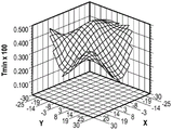
FIGS. 13-15 are schematic diagrams of the minimum transmission (Tmin) of the reflective polarizer in front plan view;
FIG. 16 is a schematic front view of a reflective polarizer;
FIG. 17 is a schematic representation of the maximum variation in Tmin in the region of the reflective polarizer between the center of the reflective polarizer and the optical axis through the reflective polarizer at a radius R from the center perpendicular to the reflective polarizer;
FIGS. 18-19 are schematic front plan views of a reflective polarizer showing possible changes in the block polarization state;
FIG. 20 is a schematic illustration of the maximum change in the block axis orientation in the region of the reflective polarizer between the center of the reflective polarizer and the optical axis through the reflective polarizer at a radius R from the center perpendicular to the reflective polarizer;
FIGS. 21-22 schematically illustrate possible modes of maximum transmission (Tmax) of the reflective polarizer in front plan view;
FIG. 23 is a schematic diagram of circular dichroism attenuation at a predetermined wavelength of a reflective polarizer in a front plan view;
FIG. 24 is a schematic illustration of the maximum change in circular dichroism for a region of the reflective polarizer between the center of the reflective polarizer and a radius R from the optical axis perpendicular to the reflective polarizer passing through the center of the reflective polarizer;
fig. 25 to 26 are schematic cross-sectional views of the optical system;
FIG. 27 is a graph of the ratio of the thickness of a formed reflective polarizer to the corresponding thickness of the formed reflective polarizer prior to formation;
FIG. 28 is a graph of radial stretch ratio and circumferential stretch ratio of an optical film formed during pressing;
FIG. 29 is a graph of radial stretch ratio and circumferential stretch ratio of an optical film formed during draw down;
FIG. 30 is a perspective view of a shaped reflective polarizer having five samples cut from the reflective polarizer;
FIG. 31 is a graph of block state transmission for samples cut from a reflective polarizer shaped during pressing;
FIG. 32 is a graph of block state transmission for a sample cut from a reflective polarizer shaped during pulldown;
33A-33D are graphs of the diattenuation orientation of a sample of a reflective polarizer shaped during pulldown;
FIGS. 34A-34D are graphs of the diattenuation orientation of a shaped reflective polarizer sample during pressing;
FIG. 35 is a scaled view of the change in the transmission axis of a shaped reflective polarizing film during a pulldown process;
FIG. 36 is a scaled view of the change in the transmission axis of a reflective polarizing film formed during pressing;
FIG. 37A is a graph of the average in the region with radius R of the diattenuation orientation of the reflective polarizer sample;
FIG. 37B is a graph of the maximum change in the R region with the radius of the diattenuation orientation of the reflective polarizer sample;
FIGS. 38A-38D are graphs of transmission of pass axes for samples of reflective polarizers formed during a pulldown process;
FIGS. 39A-39D are graphs of transmission of the pass axis of a sample of a reflective polarizer formed during pressing;
FIG. 40A is a graph of the average in the region with the maximum pass axis transmission radius R of a reflective polarizer sample;
FIG. 40B is a graph of the maximum variation in the region with the pass axis transmission radius R of a reflective polarizer sample;
41A-41D are graphs of block axis transmission for samples of reflective polarizers formed during pulldown;
42A-42D are graphs of block axis transmission of a sample reflective polarizer formed during pressing;
FIG. 43A is a graph of the average in the region with the maximum block axis transmission radius R of a reflective polarizer sample;
FIG. 43B is a graph of the maximum change in area with block axis transmission radius R of a reflective polarizer sample;
44A-44D are graphs of linear dichroic attenuation of a sample reflective polarizer shaped during pulldown;
45A-45D are graphs of linear dichroic attenuation of a sample reflective polarizer shaped during pressing;
FIG. 46A is a graph of the average value in the region of radius R with the maximum linear dichroic attenuation for a reflective polarizer sample;
FIG. 46B is a graph of the maximum change in the region of radius R with linear diattenuation of the reflective polarizer sample;
FIGS. 47A-47D are graphs of circular diattenuation of a sample of a reflective polarizer shaped during pulldown;
FIGS. 48A-48B are graphs of the circular diattenuation of a sample of a reflective polarizer shaped during a pressing process;
FIG. 49A is a graph of the average in a region with radius R of the circular diattenuation of the reflective polarizer sample;
FIG. 49B is a graph of the maximum change in the region of radius R of the circular diattenuation with a reflective polarizer sample;
FIG. 50 is a graph of layer thickness as a function of layer number for a reflective polarizer including two sets of interference layers; and is
Fig. 51 is a schematic cross-sectional view of an optical stack.
Detailed Description
In the following description, reference is made to the accompanying drawings, which form a part hereof and in which is shown by way of illustration various embodiments. The figures are not necessarily to scale. It is to be understood that other embodiments are contemplated and may be made without departing from the scope or spirit of the present description. The following detailed description is, therefore, not to be taken in a limiting sense.
It is known to thermoform optical films by stretching the film onto a mold surface. According to some aspects of the present description, it has been found that providing certain constraints to the stretching of an optical film can result in desirable optical properties of the film. According to some embodiments, a method of shaping an optical film is provided in which one (but not the other) of the radial stretch and the circumferential stretch of the optical film is substantially constant as the film is stretched into a usable shape. In some embodiments, the optical film is a reflective polarizer. In other embodiments, the optical film may be, for example, a mirror film. It has been found that when the reflective polarizer is stretched such that the radial stretch is substantially constant, various properties of the resulting shaped and curved reflective polarizer, further described elsewhere herein, are desirable for some applications; also, when the reflective polarizer is stretched such that the circumferential stretch is substantially constant, various characteristics of the resulting shaped and curved reflective polarizer, further described elsewhere herein, are desirable for some applications. Some of the properties resulting from holding radial stretch substantially constant may differ from those resulting from holding circumferential stretch constant, while other properties may be similar.
Substantially constant stretch from the center to the periphery of the optical film may be understood to mean that the maximum strain from the center to the periphery is at most 5% greater than the minimum strain from the center to the periphery. Substantially varying stretch from the center to the periphery of the optical film may be understood to mean that the maximum strain from the center to the periphery is at least 5% greater than the minimum strain from the center to the periphery. In some embodiments, a substantially constant stretch of the optical film from the center to the periphery of the optical film has a change in stretch from the center to the periphery of less than 5%, or less than 4%, or less than 3%, or less than 2%, or less than 1%. In some embodiments, stretch of the optical film that varies substantially from the center to the periphery of the optical film has a change in stretch of at least 5%, or at least 8%, or at least 10%, or at least 15%, or at least 20% from the center to the periphery.
Optical films (e.g., reflective polarizers) can be formed in a shape that is curved about two orthogonal axes, and can have a curved shape, such as a lens surface. After the optical film is shaped, an optical lens may be formed on the optical film by, for example, insert molding. Lenses having optical films may be used in optical systems that utilize folded optical paths, such as those described, for example, in U.S. patent 9,557,568(Ouderkirk et al), which is hereby incorporated by reference to the extent that it does not contradict this specification. Such optical systems typically include a partial reflector adjacent to and spaced apart from a reflective polarizer, and a retarder disposed between the partial reflector and the reflective polarizer. Folded optical paths are provided for such optical systems because light rays can pass through a partial reflector, reflect from a reflective polarizer back to a partial reflector, reflect from a partial reflector, and then pass through a reflective polarizer. It is often desirable for the reflective polarizer in such optical systems to be curved about two orthogonal axes. The methods described herein may provide a reflective polarizer suitable for use in a folded optical system or other optical system where a curved reflective polarizer is desired (e.g., on a curved surface of a prism in a polarizing beam splitter). When the reflective polarizer is formed as a shaped curved reflective polarizer curved about two orthogonal axes, various optical characteristics of the reflective polarizer (e.g., a change in the location of one or more of the minimum transmission of light having a block polarization state, the block axis, linear dichroic, circular dichroic, thickness of the reflective polarizer, and band edge) are typically changed by the forming process. In some cases, some modes of the altered optical characteristic are preferred over other modes. Which mode is preferred may depend on the design of the optical system. For example, spatial variations in one or more characteristics of the reflective polarizer may compensate or partially compensate for spatial variations in characteristics of other optical elements in the optical system, and preferred spatial variations in one or more characteristics of the reflective polarizer may depend on the other optical elements in the optical system.
Fig. 1 is a schematic cross-sectional view of a formed optical film 100. Optical film 100 has a center 105, a perimeter 107, and a border portion 108. Perimeter 107 is the perimeter of portion 106 of optical film 100, which portion of optical film 100 may be or include the active portion of the optical film when used in, for example, an optical system. The border portion 108 is adjacent to the perimeter 107 and may be a portion of the optical film 100 that is clamped or otherwise secured as the optical film 100 is formed. Show that is wornAn axis 111 through the center 105 and a plane 112 perpendicular to the axis 111. The axis is perpendicular to optical film 100 at center 105. Optical film 100 has a maximum lateral dimension of 2Rm and a maximum sag of S. The radial distance from center 105 along the contour of optical film 100 is r. The radial direction is along the radial distance. The circumferential direction is a direction along a contour line of the optical film perpendicular to the radial direction. The circumferential direction in the shown cross-section is parallel to the y-axis, see the x-y-z coordinate system of fig. 1. Points on the optical film may be described using a radial arc length distance R, using a cylindrical coordinate radius R from axis 111, or using an angle phi between axis 111 and a line segment from the center of curvature of optical film 100 to a point on optical film 100. In the illustrated embodiment, optical film 100 has a radius of curvature Rc. In some embodiments, optical film 100 is aspheric and has a radius of curvature that varies with R or R. The angle phi has a maximum value phimax. In some embodiments, the optical film is used in an optical system, and axis 111 is the optical axis of the optical system. Angle 2 phimaxWhich may be understood as the field of view (FOV) of optical film 100. In some embodiments, the border portion 108 of the optical film 100 is removed prior to using the optical film 100 in an optical system.
The properties of the optical film may be specified for light incident perpendicularly on the optical film or light incident on the optical film in a direction parallel to an axis that is perpendicular to the optical film at a central location and passes through the optical film. For example, the properties of optical film 100 at location 110 may be specified for light 199 perpendicular to optical film 100 at location 110, and/or the properties of optical film 100 may be specified for light 198 incident on optical film 100 at location 110 in a direction parallel to axis 111. In some cases, the characteristics of the reflective polarizer may be specified for normally incident light 199 as well as light 198 incident on optical film 100 in a direction parallel to axis 111. For example, the transmittance and reflectance of light polarized along the block and pass axes may be specified for both light 199 and light 198. Reflectivity and transmissivity or other optical characteristics may be determined for light incident on optical film 100 from either side of optical film 100. In the illustrated embodiment, the optical film 100 protrudes toward the incident light 198 and the incident light 199. If the direction of the incident light is not specified, it can be assumed that the light is normally incident on the film. Unless otherwise specified, transmittance and reflectance or other optical properties are determined for light incident on the reflective polarizer from one side of the reflective polarizer (the side of the reflective polarizer that is convex toward incident light as shown in fig. 1).
The center position of the curved optical film may be regarded as a point on the optical film at a maximum distance from a reference plane, wherein the reference plane is a plane that does not intersect the optical film and is disposed such that at least a majority of the optical film is concave toward the reference plane, and the reference plane is such that the optical film has a maximum projected area in the reference plane.
Fig. 2 is a schematic front view of an optical film 200 that is curved about two mutually orthogonal axes (x-axis and y-axis). Optical film 200 has a center 205 and a perimeter 207. The radial direction 204 is from the center 205 generally toward the periphery 207. The circumferential direction 206 is orthogonal to the radial direction 204. The center 205 of the optical film 200 may coincide with the optical axis of the optical film 200 or a location where the optical axis of an optical system including the optical film 200 intersects the optical film 200. Shows the azimuth angle In some cases, it may be desirable to characterize
 optical film 200 in terms of an azimuthal average quantity, such as azimuthal average thickness or azimuthal average band edge wavelength. The azimuthal average magnitude is an unweighted average of the magnitude of the fixed radius (distance from center 205) over the azimuth. The azimuthal extent may depend on the radius. For example, for small radii, azimuths in the illustrated embodiment In the range of zero to 2 pi and the azimuthal average magnitude can be expressed as the magnitude is in
 The integral from 0 to 2 pi is divided by 2 pi. For large radii, azimuth
 May extend over only some subset of the
 range 0 to 2 pi. For example, for plus or minus a radius near the edge in the x-direction, azimuth in the illustrated embodiment Is a relatively narrow range centered at 0 and pi radians.
Stretching in the radial direction may be induced by a radial strain epsilonrRelative radial draw ratio λrIs characterized by λr=1+εr. Similarly, stretching in the circumferential direction may be accomplished by a strain εθRelative circumferential draw ratio λθIs characterized by λθ=1+εθ. In some embodiments, the optical film is disc-shaped or has a disc-shaped portion prior to being shaped to conform to a portion of a spherical surface having a radius of curvature Rc. In the case of axisymmetric deformation, the radial draw ratio λrAnd a circumferential draw ratio λθIs related by the following formula:

for more general deformations, the draw ratio λrAnd λθEquation 1 may not be satisfied. In the conventional thermoforming method, λrAnd λθBoth varying from a center 205 to a periphery 207. According to some embodiments of the present description, it has been found advantageous to utilize where λrAnd λθOne (but not the other) is a substantially constant formation process during formation.
In some implementations, the optical film 200 may not be rotationally symmetric about an axis through the center 205 that is perpendicular to the optical film 200 at the center 205. In this case, λrAnd λθOne (but not the other) may be substantially constant in at least one direction from the center 205 to the periphery 207. In some embodiments, λrAnd λθOne (but not the other) along each from center 205 to perimeter 207The directions are substantially constant. This may be the case, for example, when optical film 200 is rotationally symmetric about an axis passing through center 205.
In some embodiments, the mold is used in a method of shaping an optical film. In some embodiments, at least a portion of the perimeter of the optical film is secured in the plane by securing at least a portion of the border portion of the optical film between a portion of the first mold and a portion of the second mold. In some embodiments, the first mold has a curved mold surface, and pressure (e.g., air pressure) is used to displace a portion of the optical film such that the optical film conforms to the curved mold surface. The positioning of the film in place and/or securing of a portion of the optical film is typically preformed prior to stretching the optical film.
Fig. 3A is a schematic cross-sectional view of a first mold 360 having a curved mold surface 362. The first mold 360 may be manufactured via a machining operation (e.g., using diamond turning). Mold 360 and other molds described herein may be made of, for example, aluminum or aluminum alloys, stainless steel, tool steel, or other suitable alloys. In some embodiments, the mold is made of a porous material (e.g., porous aluminum) that includes open pores to allow air to flow through the mold (e.g., by drawing a vacuum). Curved die surface 362 has a maximum lateral dimension D, a maximum sag S, and a sag diameter ratio S/D. In some embodiments, S/D is at least 0.05, or at least 0.1, or at least 0.2, and may be less than 0.5 or less than 0.4. In some embodiments, the curved mold surface 362 has a first radius of curvature Rs that best fits a spherical surface, and in some embodiments, ranges from about 30mm to about 1000 mm. In some embodiments, the ratio of sag S to the first radius of curvature Rs of the best-fit sphere is in the range of about 0.02 to about 0.2, or in the range of about 0.02 to about 0.15, or in the range of about 0.02 to about 0.12, or in the range of about 0.03 to about 0.12, or in the range of 0.04 to about 0.12. In some embodiments, the optical film 300 has a sag radius ratio in any of these ranges after being formed into a curved shape.
Fig. 3B is a schematic cross-sectional view of a first mold 360 and a second mold 370 having mold surfaces 372, with an optical film 300 disposed between the first mold 360 and the second mold 370, with at least a portion of the perimeter 307 of the optical film 300 fixed in the first plane 312 such that the fixed portions do not move relative to each other. In some embodiments, the fixed portion is the entire perimeter 307. Since the border portion 308 of the optical film 300 is secured between a portion of the first mold 360 and a portion of the second mold 370, the perimeter 307 is secured. In other embodiments, only a portion of the perimeter 307 is secured. For example, the first mold 360 and the second mold may include one or more channels in which the perimeter 307 is not secured. This is shown in the cross-section of fig. 3C, for example, where channel 381 is shown and a portion of optical film 300 directly overlying channel 381 is not secured between first mold 360 and second mold 370. In the illustrated embodiment, the boundary portion 308 is disposed in a first plane 312. In other embodiments, perimeter 307 or at least a portion of perimeter 307 is disposed in plane 312, but boundary portion 308 is not completely disposed in first plane 312 due to, for example, the slope of first mold 360 and second mold 370 along boundary portion 308.
In some embodiments, second mold 370 is heated and pressure is applied in space 380 between first mold 360 and optical film 300 to force optical film 300 into contact with mold surface 372 of second mold 370, thereby heating optical film 300. Pressure (e.g., air pressure) may be applied through a channel (not shown) between the first mold 360 and the optical film 300. In other embodiments, optical film 300 is preheated prior to placement between first mold 360 and second mold 370, and/or first mold 360 is heated and the optical film is heated as it conforms to curved mold surface 362.
In some embodiments, the optical film 300 is heated to a temperature greater than the glass transition temperature of the optical film 300 prior to stretching and forming the film. The glass transition temperature of the optical film 300 may refer to the glass transition temperature of any layer of the optical film 300. For example, the glass transition temperature of the optical film 300 may be the highest glass transition temperature of any of the layers of the optical film 300, may be the lowest glass transition temperature of any of the layers of the optical film 300, may be the glass transition temperature of the birefringent interference layer of the optical film 300 when the optical film 300 includes alternating non-birefringent and birefringent layers, or the glass transition temperature of the optical film 300 may be the glass transition temperature of the higher refractive index interference layer of the optical film 300 when the optical film 300 includes alternating higher and lower refractive index interference layers.
In some embodiments, the optical film 300 is stretched by displacing a portion of the optical film 300 in at least a first direction (z-direction) perpendicular to the first plane 312 such that the radial stretch of the optical film is substantially constant from the center 305 to the perimeter 307 of the optical film 300 and the circumferential stretch of the optical film varies substantially from the center 305 to the perimeter 307 of the optical film 300. The portion of the optical film displaced relative to the perimeter 307 generally includes a portion near the center 305 of the optical film 300. In some embodiments, pressure is used to displace a portion of optical film 300. In some embodiments, after heating optical film 300, pressure (e.g., air pressure) is applied in space 382 between optical film 300 and second mold 370 through channel 381 to cause optical film 300 to conform or at least partially conform to curved mold surface 362, as shown in fig. 3D. In some embodiments, the first mold 360 is porous. In some embodiments, a vacuum or partial vacuum is pulled through first mold 360 to help conform optical film 300 to curved mold surface 362. In this case, a vacuum or partial vacuum is drawn into the space 380 between the optical film 300 and the first mold 360.
The optical film 300 is then removed from the first mold 360 and the second mold 370. Fig. 3E shows the resulting shaped optical film 300. In a subsequent processing step, a lens or other optical element may be injection molded onto the optical film 300. The border portion 308 of the optical film 300 may be removed before or after the injection molding step.
In some embodiments, at least one location 310 on the optical film 300 has a radius of curvature R1 in each of the orthogonal first and second directions (e.g., x-direction and y-direction) in a range from about 6mm to about 1000mm, or in a range from about 12mm to about 500 mm. In some embodiments, each location on the optical film 300 has a radius of curvature in a range from about 6mm to about 1000mm, or in a range from about 12mm to about 500mm, along each of the orthogonal first and second directions (e.g., x-and y-directions). In some embodiments, the radii of curvature in the first and second directions are different, but each is in the range of about 6mm to about 1000mm, or in the range of about 12mm to about 500 mm. In some embodiments, the radii of curvature in the first and second directions are substantially equal.
Fig. 3F is a schematic view of a mold 360b that corresponds to the first mold 360 and may be used in place of the first mold 360. The mold 360b has a curved mold surface 362b and at least one transition region 364. For example, the at least one transition region 364 can be a single continuous region around the edge of the curved mold surface 362 b. The at least one transition region 364 generally has a smoothly varying curvature from the curved mold surface 362b to the flat boundary portion 396. At least one transition region 364 can be included to prevent or reduce stress concentrations in the optical film. It has been found that this allows for the formation of an optical film at a reduced pressure as compared to using a mold that does not include at least one transition region 364. The mold 360b may be porous, such as described for the first mold 360.
In some embodiments, the mold is used in a method of shaping an optical film. In some embodiments, at least a portion of the perimeter of the optical film is fixed in a plane by clamping a portion of the optical film such that the fixed portions do not move relative to each other. In some embodiments, the mold has a curved mold surface, and the mold and the optical film are moved relative to each other to displace a portion of the optical film relative to a fixed portion of the perimeter such that the optical film conforms to the curved mold surface.
Fig. 4A is a schematic top view of an optical film 400 having a center 405, a perimeter 407, and a border portion 408. Fig. 4B is a schematic side view of optical film 400 disposed over mold 460. At least a portion of boundary portion 408 is clamped in clamp 473 to secure at least a portion of perimeter 407 in first plane 412 (parallel to the x-y plane). Mold 460 has a curved mold surface 462.
In some embodiments, the optical film 400 is stretched by displacing a portion of the optical film 400 in at least a first direction (z-direction) perpendicular to the first plane 412 such that the circumferential stretch of the optical film 400 is substantially constant from the center 405 to the periphery 407 of the optical film 400 and the radial stretch of the optical film 400 varies substantially from the center 405 to the periphery 407 of the optical film 400. In some embodiments, a portion of the optical film 400 near the center of the optical film 400 is displaced by varying the distance between the curved mold surface 462 and the perimeter 407 of the optical film 400 in the first direction such that at least a portion of the optical film 400 near the center 405 of the optical film 400 contacts the curved mold surface 462. The distance between curved mold surface 462 and perimeter edge 407 may be varied by moving mold 460 toward optical film 400 and/or by moving clamp 473 that secures at least a portion of perimeter edge 407 toward mold 460. Fig. 4C is a schematic side view of optical film 400 and mold 460 after clamp 473 and mold 460 and the mold have moved relative to each other. At least a portion of optical film 400 conforms to at least a portion of curved mold surface 462. In some embodiments, a vacuum or partial vacuum is drawn into the region 477 between the mold 460 and the optical film 400. In some embodiments, mold 460 is in sealed compartment 493 and pressure is applied to optical film 400 opposite mold 460. For example, air pressure may be applied in region 491. Pulling a vacuum and/or applying pressure may be done to help conform optical film 400 to curved mold surface 462.
In some embodiments, the optical film 400 has a radius of curvature within any of the ranges described elsewhere herein. For example, at least one location on optical film 400 may have a radius of curvature in a range from about 6mm to about 1000mm along each of the orthogonal first and second directions, as described for optical film 300.
Fig. 4D is a schematic diagram of how points in the optical film 400 map to points on the curved mold surface 462 according to some embodiments of the present description. First portion 488 of optical film 400 conforms to at least a portion 468 of curved mold surface 462 during stretching of optical film 400. In some embodiments, optical film 400 is disposed such that at least first portion 488 is disposed substantially in first plane 412 adjacent to curved mold surface 462. The first plane 412 may be positioned at a distance (in the z-direction in fig. 4D) from the closest point on the curved mold surface 462 that is in the range of zero to 100 times the sag of the curved mold surface 462 or the sag of the portion 468 of the curved mold surface 462. In some embodiments, optical film 400 is then stretched to conform first portion 488 of the optical film to at least a portion 468 of curved mold surface 462. This stretching may be performed as shown and described in fig. 4A-4C. In some embodiments, stretching is such that each point 480 in first portion 488 has a location 482 on curved mold surface 462 that lies within cone 484, which prior to stretching has an apex 485 at location 481 of point 480 in first plane 412. In some embodiments, the cone 484 is centered along an axis 486 perpendicular to the first plane 412 and has a cone angle σ of no more than 10 degrees, or no more than 5 degrees.
A film or portion of a film can be said to be substantially in a plane if the film or portion is in the plane, or if the maximum deviation of the film or portion from the plane is no more than 20% of the maximum lateral dimension of the film or portion (the maximum dimension in the front plan view). In some embodiments, the maximum deviation of the film or portion from the plane is no more than 10% or no more than 5% of the maximum lateral dimension.
Fig. 4E is a schematic view of a mold 460b corresponding to mold 460 and that may be used in place of mold 460. Mold 460b has a curved mold surface 462b and at least one transition area 464. For example, the at least one transition area 464 can be a single continuous area around the edge of the curved die surface 462 b. At least one transition area 464 can have a smoothly varying curvature from curved mold surface 462b to boundary portion 496. At least one transition region 464 may be included to prevent or reduce stress concentrations in the optical film. The desired shape of transition region 464 may depend on the location of clip 473 when optical film 400 is at least partially conformed to curved mold surface 462 b. It has been found that this allows for the formation of an optical film at a reduced pressure as compared to using a mold that does not include at least one transition region 464.
FIG. 5 is a schematic front view of a curved reflective polarizer 500. In some implementations, the curved reflective polarizer 500 includes a plurality of polymer layers stretched and shaped at least in orthogonal first and second directions 520 and 530 such that at least one location on the curved reflective polarizer has a radius of curvature in a range of about 6mm to about 1000mm or in a range of about 12mm to about 500mm in each of the first and second directions 520 and 530. In some embodiments, each location 10 on the reflective polarizer 500 has a maximum reflectance greater than about 70% for the block polarization state 20. In some implementations, each location 10 on the reflective polarizer 500 has a maximum throw ratio for the orthogonal pass polarization state 30 of greater than about 70%. In some embodiments, each location 10 on the reflective polarizer 500 has a minimum transmission of less than about 5% for the block polarization state 20. For normally incident light at a predetermined wavelength, a predetermined range of wavelengths, or a predetermined plurality of wavelengths (e.g., a wavelength range of 400nm to 700nm) or above the reflection band of the reflective polarizer 500, the maximum reflectance, maximum transmittance, and minimum transmittance may be within these ranges. Alternatively or additionally, for light of a predetermined wavelength, a predetermined range of wavelengths, or a predetermined plurality of wavelengths, or light incident on the reflective band of the reflective polarizer 500 in a direction parallel to an axis perpendicular to and passing through the reflective polarizer at the center of the reflective polarizer, the maximum reflectance, the maximum transmittance, and the minimum transmittance may be within these ranges. The reflectance and transmittance may be expressed as a fraction rather than a percentage. For example, a reflectance of 70% or a transmittance of 70% is equivalent to a reflectance of 0.7 or a transmittance of 0.7, respectively.
The predetermined wavelength range may be a wavelength range over which an optical system including the optical film is designed to operate. For example, the predetermined wavelength range may be the visible range (400nm to 700 nm). As another example, the predetermined wavelength range may include one or more visible wavelength ranges. For example, the predetermined wavelength range may be a union of more than one narrow wavelength range (e.g., a union of disjoint red, green, and blue wavelength ranges corresponding to the emission color of the display panel). Such wavelength ranges are further described in U.S. patent publication 2017/0068100(Ouderkirk et al), which is hereby incorporated by reference to the extent that it does not contradict the present specification. In some embodiments, the predetermined wavelength range includes other wavelength ranges (e.g., infrared (e.g., near infrared (about 700nm to about 2500nm)) or ultraviolet (e.g., near ultraviolet (about 300nm to about 400nm)) as well as visible wavelength ranges.
In some implementations, the thickness of reflective polarizer 500 is at least 5% greater at the center 505 of the reflective polarizer than at least one edge location (e.g., edge locations 50, 51, 52, and 53 near edges 60, 61, 62, and 63, respectively). For example, in some embodiments, the thickness is greater at the center 505 than at least one edge location when the reflective polarizer 500 is shaped during a process in which the circumferential stretch is substantially constant and the radial stretch varies substantially with radial position. Suitable processes include those described as shown in fig. 4A through 4E. In some implementations, the thickness of the reflective polarizer 500 decreases substantially monotonically from the center 505 to at least one edge location of the reflective polarizer 500.
An edge position near an edge refers to a position on the reflective polarizer that is closer to the edge of the reflective polarizer than to the center of the reflective polarizer. In some embodiments, the arc length from the edge to the edge location is less than 50%, or less than 40%, or less than 30%, or less than 20% or less than 10% of the arc length from the center to the edge location.
In some implementations, the thickness of the reflective polarizer 500 is at least 5% less at the center 505 of the reflective polarizer than at least one edge location (e.g., edge locations 50, 51, 52, and 53). For example, in some embodiments, the thickness is less at the center 505 than at least one edge location when the reflective polarizer 500 is shaped during radial stretch is substantially constant and circumferential stretch varies substantially with radial position. In some embodiments, the forming process is as described and illustrated in fig. 3A through 3F. In some implementations, the thickness of the reflective polarizer 500 increases substantially monotonically from the center 505 to at least one edge location of the reflective polarizer 500.
In some embodiments, for light having a predetermined wavelength and incident on the reflective polarizer in a direction parallel to the axis (z-axis), each location 10 on the reflective polarizer 500 has a maximum reflectance greater than about 0.7 for the block polarization state 20 and a maximum transmittance greater than about 0.7 for the orthogonal pass polarization state 30 that is perpendicular to and passes through the reflective polarizer 500 at the central location 505 such that the maximum transmittances for the pass polarization state 30 for at least one first location (e.g., location 52 or location 55) and at least one second location (e.g., location 50) differ from each other by at least 3.8%, or at least 4%, or at least 4.2%, or at least 4.4%, or at least 4.5%. In some embodiments, the maximum transmission for the pass polarization state 30 for the at least one first location and the at least one second location differ from each other (e.g., (greater minus lesser)/greater multiplied by 100%) by no more than 6%, or no more than 5.5%, or no more than 5.0%. For example, the maximum transmittance at the first position may be 0.90, and the maximum transmittance at the second position may be 0.86. In this case, the maximum transmittances differ from each other by (0.90-0.86)/0.90 x 100%, being about 4.4%.
In some embodiments, the at least one first location and the at least one second location (e.g., locations 52 and 50) are proximate to an edge (60 and 62, respectively) of reflective polarizer 500 and form an angle θ in a range of about 70 degrees to about 110 degrees with respect to center 505. In this case, the maximum transmission change is characteristic of the process of forming the reflective polarizer, where the radial stretch is substantially constant. In some embodiments, the maximum transmission for the pass polarization state 30 for the first location (e.g., location 52) is no less than 0.83, and the maximum transmission for the pass polarization state for the second location (e.g., location 50) is no more than 0.81.
In some embodiments, at least one first location (e.g., location 55) is near center location 505 (closer to center location 505 than to the nearest edge) and at least one second location (e.g., location 50) is near the edge of reflective polarizer 500. In this case, the maximum transmission change is characteristic of the process of forming the reflective polarizer, where the circumferential stretch is substantially constant. In some embodiments, the maximum transmission for the pass polarization state at the first location is no less than 0.89, and the maximum transmission for the pass polarization state at the second location is no more than 0.87.
FIG. 6 is a schematic illustration of the thickness of a reflective polarizer from a center position to an edge position. The center position has a thickness of Tc and the edge position has a thickness of Te. In some embodiments, Tc is at least 5% greater than Te. This condition can be expressed as (Tc-Te)/Te ≧ 0.05. In some embodiments, (Tc-Te)/Te ≧ 0.1, or 0.15 or 0.2. In the illustrated embodiment, the thickness decreases substantially monotonically from the center position to the edge position. In some embodiments, the thickness variation is produced by forming the reflective polarizer during a substantially constant circumferential stretch. Suitable processes include those described and illustrated in fig. 4A-4E, which may be referred to as a pulldown process. In some embodiments, the thickness decreases substantially monotonically from the center to the at least one edge location along an arc from the center to each of the at least one edge location. In some embodiments, the thickness decreases substantially monotonically from the center to the edge along an arc from the center to each location near the edge. In some cases, it is useful to characterize the thickness in terms of an azimuthal average of the thickness. In some implementations, the azimuthal average thickness is greater at the center of the reflective polarizer than at edge locations of the at least one edge location. In some implementations, the azimuthal average thickness decreases substantially monotonically from the center to the edge location of the reflective polarizer. In some embodiments, the azimuthal average thickness corresponds to the thickness depicted in fig. 6.
If the amount at any of the larger intermediate points in the range (such as the thickness or band edge wavelength) is less than or about equal to the amount at any of the smaller intermediate points in the range, it can be said that the amount decreases substantially monotonically over a range from a first end point of the range (e.g., the center position of the reflective polarizer) to a second end point of the range (e.g., the edge position of the reflective polarizer). Similarly, if the amount at any greater intermediate point in the range is greater than or about equal to the amount at any lesser intermediate point in the range, it can be said that the amount substantially monotonically increases in the range from the first end of the range to the second end of the range. For an amount that varies with position over a range (e.g., thickness or band edge wavelength over a range of positions from a center position to an edge position), the amount at a point may be said to be about equal to a value (e.g., the amount at another point) if the amount at that point is equal to that value, or if the amount at that point is within a range of that value plus or minus the maximum of the amount within the range minus 5% of the minimum. The quantities described as being substantially monotonically decreasing or substantially monotonically increasing may be monotonically decreasing or monotonically increasing, respectively. The quantities described as substantially monotonically decreasing or substantially monotonically increasing may be strictly monotonically decreasing or strictly monotonically increasing, respectively. If f (x 2). ltoreq.f (x1) for any x1 and x2 that satisfy x2 ≧ x1, the function f (x) of variable x is monotonically decreasing. If f (x2) < f (x1) for any x1 and x2 that satisfy x2> x1, the function f (x) of variable x decreases strictly monotonically. Similarly, if f (x2) ≧ f (x1) for any x1 and x2 that satisfy x2 ≧ x1, the function f (x) of variable x is monotonically increasing; and if f (x2) > f (x1) for any x1 and x2 within the range satisfying x2> x1, the function f (x) of the variable x strictly monotonically increases.
FIG. 7 is a schematic illustration of the thickness of a reflective polarizer from a center position to an edge position. The center position has a thickness of Tc and the edge position has a thickness of Te. In some embodiments, Tc is at least 5% less than Te. This condition can be expressed as (Te-Tc)/Te.gtoreq.0.05. In some embodiments, (Te-Tc)/Te ≧ 0.1, or 0.15 or 0.2. In the illustrated embodiment, the thickness increases substantially monotonically from the center position to the edge position. In some embodiments, the thickness variation is produced by forming the reflective polarizer during radial stretching to be substantially constant. Suitable processes include those described and illustrated in fig. 3A through 3F, which may be referred to as pressurized processes. In some cases, it is useful to characterize the thickness in terms of an azimuthal average of the thickness. In some implementations, the azimuthal average thickness is less at a center of the reflective polarizer than at an edge location of the at least one edge location. In some implementations, the azimuthal average thickness increases substantially monotonically from the center to the edge location of the reflective polarizer. In some embodiments, the azimuthal average thickness corresponds to the thickness depicted in fig. 7.
FIG. 8 is a schematic illustration of the reflectance as a function of wavelength for light perpendicularly incident on a reflective polarizer in either a block or pass polarization state. A predetermined wavelength range from λ 1 to λ 2 is shown. The average reflectivity at a predetermined wavelength for normally incident light having the block polarization state is Rb, which may be at least 70%, or at least 80%, or at least 85% or at least 90%. The average reflectance at a predetermined wavelength for normally incident light having a pass polarization state is Rp, which may be less than 20%, or less than 15%, or less than 10%, or less than 5%. The reflective polarizer has a reflection band 847 with a long wavelength band edge λ 3. The reflection band typically has both long and short wavelength band edges, where the reflectivity drops off rapidly. In an exemplary embodiment, the short wavelength band edge is less than λ 1, and the long wavelength band edge λ 3 is greater than λ 2. The band edge can be determined for normally incident light while the reflective polarizer is convex toward the incident light.
FIG. 9 is a schematic illustration of the transmittance as a function of wavelength of a reflective polarizer for light perpendicularly incident on the reflective polarizer in either a block or pass polarization state. The average transmission at a predetermined wavelength (from λ 1 to λ 2) for normally incident light having a pass polarization state is Tp, which may be at least 70%, or at least 80%, or at least 85% or at least 90%. The average transmission at a predetermined wavelength for normally incident light having the block polarization state is Tb, which may be less than 10%, or less than 5%, or less than 3%, or less than 2%, or less than 1%, or less than 0.5%.
Several different criteria may be used to define the exact wavelength of the band edge. The spatial variation pattern exhibited by the band edges (e.g., monotonically decreasing or monotonically increasing with radius) is generally not dependent on the precise criteria used. The band-edge wavelengths can be considered, for example, as wavelengths where the reflectivity for normally incident light with block polarization state is reduced to 1/2Rb or where the transmittance for normally incident light with block polarization state is increased to 10%. Unless otherwise indicated, band edges may be understood to refer to wavelengths at which the transmission increases to 10% for normally incident light having a block polarization state.
FIG. 10 is a schematic of a long wavelength band edge from a center position to an edge position of a reflective polarizer. The center position has a long wavelength band edge of λ c, and the edge position has a long wavelength band edge of λ e. In some embodiments, λ c is at least 5% greater than λ e. This condition can be expressed as (λ c- λ e)/λ e ≧ 0.05. In some embodiments, (λ c- λ e)/λ e ≧ 0.1, or 0.15 or 0.2. In the illustrated embodiment, the long wavelength band edge decreases substantially monotonically from a center position to an edge position. In some embodiments, the long wavelength band edge variation is produced by forming a reflective polarizer during a substantially constant circumferential stretch. Suitable processes include those described and illustrated in fig. 4A through 4E. In some cases, it is useful to characterize the long wavelength band edge in terms of the azimuthal average of the long wavelength band edge. In some implementations, the azimuthally averaged long wavelength band edge is greater at the center of the reflective polarizer than at an edge location of the at least one edge location. In some implementations, the azimuthally averaged long wavelength band edge decreases substantially monotonically from the center to the edge position of the reflective polarizer. In some implementations, the azimuthally averaged long wavelength band edge corresponds to the long wavelength band edge depicted in fig. 10.
FIG. 11 is a schematic of a long wavelength band edge from a center position to an edge position of a reflective polarizer. The center position has a long wavelength band edge of λ c, and the edge position has a long wavelength band edge of λ e. In some embodiments, λ c is at least 5% less than λ e. This condition can be expressed as (λ e- λ c)/λ e ≧ 0.05. In some embodiments, (λ e- λ c)/λ e ≧ 0.1, or 0.15 or 0.2. In the illustrated embodiment, the long wavelength band edge increases substantially monotonically from a center position to an edge position. In some embodiments, the long wavelength band edge variation is produced by forming a reflective polarizer during radial stretching to be substantially constant. Suitable processes include those described and illustrated in fig. 3A through 3F. In some implementations, the azimuthally averaged long wavelength band edge is smaller at the center of the reflective polarizer than at an edge location of the at least one edge location. In some implementations, the azimuthally averaged long wavelength band edge increases substantially monotonically from the center to the edge position of the reflective polarizer. In some embodiments, the azimuthal average long wavelength band edge corresponds to the long wavelength band edge depicted in figure 11.
Fig. 12 is a schematic cross-sectional view of an integrally formed reflective polarizer 1200 that includes a plurality of interference layers 1234 and non-interference layers 1233. In some embodiments, the plurality of interference layers includes alternating polymer layers 1236 and 1237. In the illustrated embodiment, a single non-interference layer 1233 is included. An interference layer may be described as reflecting or transmitting light primarily by optical interference when the reflectivity and transmissivity of the interference layer can be reasonably described by optical interference, or can be reasonably accurately modeled as it results from optical interference. Such interference layers are described, for example, in U.S. Pat. No. 5,882,774(Jonza et al) and U.S. Pat. No. 6,609,795(Weber et al). When a pair of adjacent interference layers having different refractive indices have a combined optical thickness (refractive index multiplied by physical thickness) of 1/2 wavelengths of light, the pair reflects light by optical interference. The interference layer typically has a physical thickness of less than about 200 nanometers. The non-interference layer has an optical thickness too large to reflect visible light via interference. Typically, the non-interference layer has a physical thickness of at least 1 micron. In some embodiments, more than one non-interference layer is included. In some embodiments, the plurality of interference layers 1234 are disposed on the same side of at least one non-interference layer 1233. In some embodiments, at least one non-interference layer (non-interference layer 1233 in the illustrated embodiment) is integrally formed with the plurality of interference layers 1234 and does not reflect or transmit light primarily by optical interference. In some embodiments, the non-interference layer 1233 is a non-tacky flexible optical layer, as further described elsewhere herein.
Suitable materials for the higher index interference layer in a reflective polarizing film, such as reflective polarizer 1200, include, for example, polyethylene naphthalate (PEN), a copolymer containing PEN and a polyester (e.g., polyethylene terephthalate (PET) or dibenzoic acid), ethylene glycol-modified polyethylene terephthalate. Suitable materials for the lower index interference layer in a reflective polarizing film, such as reflective polarizer 1200, include, for example, PEN-based copolyesters, PET-based copolyesters, Polycarbonate (PC), or blends of the three types of materials. To achieve high reflectivity with a desired number of layers, adjacent microlayers may exhibit a refractive index difference for light polarized along the block axis of at least 0.2, for example.
As used herein, a first element "integrally formed" with a second element means that the first and second elements are manufactured together, rather than separately, and then the two elements are subsequently joined. Integrally forming includes fabricating a first component and then fabricating a second component on the first component. A reflective polarizer comprising multiple layers is integrally formed if the layers are fabricated together (e.g., casting a film from a combined melt stream, and then orienting the cast film) rather than separately and then the layers are subsequently joined.
In some embodiments, reflective polarizer 1200 has a different reflectivity for light incident in the block state from first major side 1238 than for light incident in the block state from second major side 1239, as further described elsewhere herein.
The average total thickness of the plurality of interference layers 1234 is Tint and the average total thickness of the at least one non-interference layer 1233 is Tnon. In some embodiments, Tint is in the range of about 20 microns to about 70 microns, and Tnon is in the range of about 40 microns to about 100 microns. If the surface of one or more non-interference layers is structured, the total thickness may vary. The overall thickness may also vary due to, for example, common manufacturing variations. The average total thickness is an unweighted average of the thickness over the area of the layers. In some embodiments, the reflective polarizer has an average total thickness (Tint + Tnon) of at least 50 microns, or at least 60 microns, or at least 70 microns.
In some embodiments, at least one of the interference layers is substantially uniaxially oriented prior to forming the film into the curved shape. For example, each of the layers 1237 may be substantially uniaxially oriented. A layer in a reflective polarizer or reflective polarizer is substantially uniaxially oriented if the layer is substantially oriented in an in-plane direction and substantially unoriented in an orthogonal in-plane direction and substantially unoriented in a thickness direction. Substantially uniaxially oriented reflective polarizers are available from 3M company (3M company) under the trade name Advanced Polarizing Film or APF. Other types of multilayer optical film reflective polarizers (e.g., reflective polarizing brightness enhancement film or DBEF available from 3M company) can also be used. The DBEF film is oriented substantially more in the in-plane direction than in the orthogonal in-plane direction, and also exhibits orientation in the thickness direction. DBEF films are not substantially uniaxially oriented as "substantially uniaxially oriented" as used herein.
In some implementations, the reflective polarizer is substantially uniaxially oriented prior to forming the curved shape because the reflective polarizer has a degree of uniaxiality U of at least 0.7, or at least 0.8, or at least 0.85, where U ═ (1/MDDR-1)/(TDDR)1/2-1), MDDR is defined as the machine direction stretch ratio and TDDR is defined as the cross direction stretch ratio. Such substantially uniaxially oriented multilayer optical films are described in U.S. patent 2010/0254002(Merrill et al), which is hereby incorporated by reference to the extent not inconsistent with this specification, and may include a plurality of alternating first and second polymer layers, the first polymer layer havingThe refractive index is substantially the same in the length direction (e.g., x-direction) and the thickness direction (e.g., z-direction) but substantially different from the refractive index in the width direction (e.g., y-direction). For example, the absolute value of the difference between the refractive indices in the x-direction and the z-direction may be less than 0.02 or less than 0.01, and the absolute value of the difference between the refractive indices in the x-direction and the y-direction may be greater than 0.05 or greater than 0.10. Unless otherwise indicated, refractive index refers to the refractive index at a wavelength of 550 nm. After forming the curved shape, the reflective polarizer may have at least one layer that is substantially uniaxially oriented in at least one location. In some embodiments, at least one layer at least one location has a first refractive index in a first direction along the thickness of the layer, a second refractive index in a second direction orthogonal to the first direction, and a third refractive index in a third direction orthogonal to the first and second directions, and the absolute value of the difference between the first and third refractive indices is less than about 0.02 or less than about 0.01, and the absolute value of the difference between the second and third refractive indices is greater than about 0.05 or greater than about 0.10. In some implementations, after forming the curved shape, the reflective polarizer has at least one layer that is substantially uniaxially oriented at a plurality of locations.
While reflective polarizing films that are not substantially uniaxially oriented (e.g., DBEF films) can have a total thickness greater than 100 microns, substantially uniaxially oriented films (e.g., APF films) are typically much thinner. For example, APF films typically have a thickness of less than about 35 microns. In accordance with the present description, thick (e.g., greater than about 50 microns thick) substantially uniaxially-oriented reflective polarizing films have been found to provide improved properties when formed into curved shapes and used in optical systems, as further described elsewhere herein. The improved properties include improved mechanical properties and improved optical properties. The improved mechanical properties include improved formability to achieve higher curvature or higher sag diameter ratio without creating defects in the film. The improved optical properties include improved polarization contrast when used in optical systems utilizing folded optical designs, as further described elsewhere herein. In addition to or instead of using a thick reflective polarizing film, it has been found that a non-stick flexible optical film is bonded to the reflective polarizer prior to formation to improve physical properties. The thickness of the reflective polarizer may be increased by including additional interference layers within a given thickness range and/or by increasing the thickness of the non-interference layers.
In some embodiments, the reflective polarizer includes two or more alternating polymer interference layer groupings to provide high contrast. Such reflective polarizers are further described in U.S. provisional patent application 62/467712(Haag et al), filed on 2017, 3, 6, which is hereby incorporated by reference to the extent not inconsistent with this specification. In some embodiments, the reflective polarizer includes a plurality of packets, wherein each packet has a substantially continuous curve of layer thickness as a function of layer number. Fig. 50 shows the variation of layer thickness with layer number for a reflective polarizer comprising two packets (packet 1 and packet 2). In some embodiments, the thickness profiles substantially overlap (e.g., greater than 50% of the thickness range of grouping 1 overlaps with greater than 50% of the thickness range of grouping 2). In other embodiments, there is little or no overlap in the thickness ranges.
After the reflective polarizer is shaped, the previously uniaxially oriented layer or layers may no longer be uniaxially oriented in all positions. However, in some embodiments, after formation, at least one layer is substantially uniaxially oriented in at least one location. For example, the reflective polarizing film may be radially stretched during the formation of the film, and radially stretched at a position along a curve from the center position of the reflective polarizer. For example, referring to fig. 19, in some embodiments, at least one layer (e.g., corresponding to layer 1237 and/or layer 1236 depicted in fig. 12) is substantially uniaxially oriented at center 1905 and location 1910-5. In the embodiment shown in FIG. 19, the orientation at location 1910-5 is along block axis 1910b-5, which is parallel to block axis 1905b at center 1905 when projected onto the x-y plane. In some embodiments, the reflective polarizer is substantially uniaxially oriented at least one of a central location of the reflective polarizer and a location remote from the central location of the reflective polarizer.
In some embodiments, for light having a predetermined wavelength and incident normally on the reflective polarizer or in a direction parallel to an axis passing through the center of the reflective polarizer and perpendicular to the reflective polarizer, each location on the reflective polarizer has a maximum reflectance for the block polarization state, a maximum transmittance for the orthogonal pass polarization state, and a minimum transmittance for the block polarization state. In some embodiments, the maximum reflectance is greater than about 70%. In some embodiments, the maximum transmission is greater than about 70%. In some embodiments, the minimum transmission is less than about 5%.
Fig. 13 is a schematic diagram of a minimum transmission (Tmin) of a reflective polarizer 1300 to block a polarization state of light at a predetermined wavelength (e.g., about 550nm) according to some embodiments of the present description. The illustrated Tmin may be determined for light parallel to the z-axis or for normally incident light, with the reflective polarizer projecting toward the incident light. Contour lines 1372 for constant Tmin are shown. It has been found that the illustrated contour lines 1372 are characteristic of reflective polarizing films formed into curved shapes using a method in which circumferential stretching is substantially constant, according to some embodiments.
Orthogonal first and second axes 1320, 1330 that intersect each other at a central location 1305 of the reflective polarizer 1300 and orthogonal third and fourth axes 1325, 1335 that intersect each other at the central location 1305 of the reflective polarizer 1300 are shown. The angle ξ between the first axis 1320 and the third axis 1325 is about 45 degrees. In some implementations, Tmin is small and substantially constant along the first axis 1320 and the second axis 1330, and substantially increases away from the center position 1305 along each of the third axis 1325 and the fourth axis 1335. In some implementations, the blocking axis of the reflective polarizer 1300 at the center position 1305 is along the second axis 1330.
In some embodiments, the minimum transmission for the block polarization state of the reflective polarizer 1300: t1 at first position 1313 along first axis 1320 between center position 1305 and first edge 1360 of reflective polarizer 1300; a second position 1315 along a second axis 1330 between center position 1305 and second edge 1362 of reflective polarizer 1300 at T2; a third location 1317 along a third axis 1325 between the central location 1305 and the third edge 1374 of the reflective polarizer is T3; and T4 at a fourth location 1319 along a fourth axis 1335 between the center location 1305 and the fourth edge 1378 of the reflective polarizer 1300. In some embodiments, the maximum values of T1 and T2 are less than the minimum values of T3 and T4. In some embodiments, the minimum transmission for the block polarization state of the reflective polarizer 1300: a fifth position 1314 along a first axis 1320 between a center position 1305 and a fifth edge 1361 of the reflective polarizer 1300 opposite the first edge 1360 is T5; a sixth position 1316 along a second axis 1330 between the central position 1305 of the reflective polarizer and a sixth edge 1363 opposite the second edge 1362 is T6; a seventh location 1318 along a third axis 1325 between the center location 1305 of the reflective polarizer 1300 and a seventh edge 1375 opposite the third edge 1374 is T7; at an eighth location 1321 along fourth axis 1335 between center location 1305 and an eighth edge 1379 opposite fourth edge 1378 of reflective polarizer 1300 is T8. In some embodiments, the maximum value of T1, T2, T5, and T6 is less than the minimum value of T3, T4, T7, and T8.
In some implementations, the minimum transmission Tmin for the block polarization state of the reflective polarizer 1300 is substantially 4 times rotationally symmetric about an optical axis (parallel to the z-axis) perpendicular to the reflective polarizer with respect to a center position 1305 through the reflective polarizer 1300. An amount is n times rotationally symmetric if the amount is symmetric in all rotations of about 360 degrees/n, where n is an integer greater than 1. A quantity characterizing a reflective polarizer may be described as substantially symmetric under symmetry operations (e.g., reflection about an axis or plane or rotation through an angle) if the quantity at each point in at least 70% of the surface area of the reflective polarizer differs from the quantity at the corresponding point determined by the symmetry operations by no more than 20% of the maximum variation of the quantity. For example, if Tmin at each point in at least 70% of the surface area of the reflective polarizer differs by no more than 20% of the maximum variation of Tmin from the minimum transmission at the corresponding point determined by rotation of each of 90, 180, and 270 degrees about the optical axis, the minimum transmission (Tmin) of the reflective polarizer 1300 is substantially 4-fold symmetric about the optical axis. The maximum change in Tmin is the maximum Tmin minus the minimum Tmin of the reflective polarizer. In some embodiments, the amount at each point of at least 70%, or at least 80%, or at least 90%, or at least 95% of the surface area of the reflective polarizer differs from the amount at the corresponding point determined by the symmetry operation by no more than 20%, or no more than 15%, or no more than 10%, or no more than 5% of the maximum variation of the amount.
In some implementations, Tmin is substantially symmetric in reflection about any one or more of the first axis 1320, the second axis 1330, the third axis 1325, and the fourth axis 1335. Reflection about an axis refers to reflection about an axis in a plan view or reflection about an axis projected onto a plane perpendicular to an optical axis passing through the center of the reflective polarizer and perpendicular to the reflective polarizer. Reflection symmetry can also be characterized by reflection about a plane. The quantities described as symmetrical or anti-symmetrical about an axis may also be symmetrical or anti-symmetrical about a plane containing the axis and the optical axis of the reflective polarizer. In some implementations, Tmin is substantially symmetric, under reflection, about each of one or more planes including the optical axis and any of the first axis 1320, the second axis 1330, the third axis 1325, and the fourth axis 1335.
In other embodiments, Tmin is relatively larger in a first portion of the reflective polarizer along a third axis 1325 and decreases away from that portion along a fourth axis 1335. This is schematically illustrated in fig. 14.
Fig. 14 is a schematic diagram of a minimum transmission (Tmin) of a reflective polarizer 1400 blocking a polarization state of light at a predetermined wavelength according to some embodiments of the present description. The illustrated Tmin may be determined for light parallel to the z-axis or for normally incident light, with the reflective polarizer projecting toward the incident light. Contour lines 1472a and 1472b for a constant Tmin are shown. A continuous first portion 1471 of the reflective polarizer 1400 extends between a first end 1474 and a second end 1475 of the reflective polarizer 1400 and has at least 3%, or at least 5%, or at least 8%, or at least 10% of the maximum lateral dimension D (maximum dimension in front plan view) of the reflective polarizer 1400. In some embodiments, the width W is no more than 80%, or no more than 70%, or no more than 60%, or no more than 50% or no more than 40% of D. The first portion 1471 defines the unbonded second and third portions 1466, 1476 of the reflective polarizer 1400 as a portion of the reflective polarizer 1400 that is not included in the first portion 1471. In some embodiments, Tmin is generally larger in the first portion 1471 and smaller in the second and third portions 1466, 1476. It has been found that this behavior of Tmin is a characteristic of reflective polarizing films formed into curved shapes using a process in which radial stretching is substantially constant according to some embodiments. Tmin is generally greater in the first portion 1471 and generally less in the second and third portions 1466, 1476, which may be understood to mean that the minimum transmission for the block polarization state of the reflective polarizer 1400 is higher at each location greater than 50% of the first portion 1471 than at each location greater than 50% of the second portion 1466 and greater than 50% of the third portion 1476. In other words, for a first region in the first portion 1471, a second region in the second portion 1466, and a third region in the third portion 1476, where the first region is greater than 50% of the total area of the first portion 1471, the second region is greater than 50% of the total area of the second portion 1466, and the third region is greater than 50% of the total area of the third portion 1476, the minimum transmittance of the reflective polarizer 1400 for the block polarization state is higher at each location in the first region than at each location in the second and third regions. The first region, the second region, and/or the third region may be continuous or discontinuous. In some embodiments, the minimum transmission of the reflective polarizer 1400 for the block polarization state is higher at each location that is greater than 60%, or 70%, or 80%, or 90% of the first portion 1471 than at each location that is greater than 60%, or 70%, or 80%, or 90% of the second portion 1466 and at each location that is greater than 60%, or 70%, or 80%, or 90% of the third portion 1476.
The first portion 1471 may extend in a substantially constant direction as schematically shown in fig. 14, or the first portion 1471 may have a curved shape. In embodiments where the first portion 1471 extends substantially along the constant direction, the minimum transmission of the block polarization state (Tmin) may be substantially symmetric about the constant direction under reflection, or may be substantially symmetric about a plane containing the optical axis (parallel to the z-axis) and the constant direction under reflection. In embodiments where the first portion has a curved shape, Tmin may not have an axis of symmetry or a plane of symmetry. Fig. 15 is a schematic diagram of Tmin at a predetermined wavelength for a reflective polarizer 1500 according to some embodiments of the present description. Elements 1571, 1574, 1575, 1572a, 1572b, 1566, and 1576 are as described for elements 1571, 1574, 1575, 1572a, 1572b, 1566, and 1576, respectively, except that first portion 1571 extends along a curve between first end 1574 and second end 1575 of reflective polarizer 1500. The reflective polarizers of fig. 14 to 15 may have a light blocking axis parallel to the y-axis at the center of the reflective polarizer.
In some cases, the reflective polarizers of the present description can be characterized by a range of amounts of a region as a function of the region. The range of the amount of the region is the maximum value of the amount in the region minus the minimum value of the amount in the region, and may be referred to as the maximum change in the amount of the region. In some cases, it is useful to consider the area within the arc length R of the center of the reflective polarizer or within the radius R (cylindrical coordinate distance from an axis passing through the center of the reflective polarizer; see, e.g., FIG. 1) of the center of the reflective polarizer. FIG. 16 is a schematic front plan view of a reflective polarizer 1600 having a center position 1605 and having a region 1627 within a radius R from the center position 1605 perpendicular to the optical axis of the reflective polarizer 1600 through the reflective polarizer 1600. The reflective polarizer 1600 has a maximum radius Rm from the optical axis. In some cases, the region 1627 may be characterized by the area of the region 1627 of the reflective polarizer 1600 (the area of the curved surface) rather than the radius R.
FIG. 17 is a schematic representation of the maximum variation in Tmin in the region of the reflective polarizer between the center of the reflective polarizer and the optical axis through the reflective polarizer at a distance of radius R from the center perpendicular to the reflective polarizer. Curve 1726 is the range of Tmin within a region having a radius R (see, e.g., region 1627 depicted in fig. 16) for a reflective polarizer formed into a curved shape using a method in which the circumferential stretch of the film is substantially constant. Curve 1723 is the range of Tmin within the region having radius R for a reflective polarizer formed into a curved shape using a method in which the radial stretch of the film is substantially constant. In some embodiments, since R is in the range of 0.4 to 0.7 times the maximum radius Rm, the maximum change in minimum transmission (expressed as a fraction rather than a percentage) of the block polarization state is in the range of about 0.001 to about 0.005. In some embodiments, the maximum change in minimum transmission for the block polarization state is in the range of about 0.001 to about 0.003 (e.g., for curve 1723) for an R/Rm of about 0.6. In some embodiments, the maximum change in minimum transmission for the block polarization state is in the range of about 0.001 to about 0.003 (e.g., for curve 1726) for an R/Rm of about 0.6.
Another quantity that can be used to characterize a reflective polarizer is the change in the polarization state of the block light. For example, the relative orientation of the block axes at different locations may be specified, and/or the maximum change in block polarization state may be specified in a region of the reflective polarizer between the center of the reflective polarizer and a radius R from the optical axis passing through the center of the reflective polarizer perpendicular to the reflective polarizer. The block polarization state or block axis can be described by the direction or orientation projected onto a plane perpendicular to the optical axis through the center of the reflective polarizer perpendicular to the reflective polarizer. The angular change in this direction is a change in the polarization state of the block light and can be expressed in degrees. The block axis may be determined for light parallel to an axis passing through and perpendicular to the center of the reflective polarizer, which is convex toward the incident light.
FIG. 18 is a schematic front plan view of a reflective polarizer 1800 showing possible changes in the block polarization state. The center 1805 of the reflective polarizer 1800 has a block polarization state characterized by a block axis 1805 b. Positions 1810-1, 1810-2, 1810-3, and 1810-4 have block polarization states characterized by block axes 1810b-1, 1810b-2, 1810b-3, and 1810b-4, respectively. The change in the block axis can be quantified by the angle between the block axis and the block axis 1805b at the center 1805, as determined in projection onto a plane (x-y plane) orthogonal to an axis perpendicular to the reflective polarizer 1800 through the center 1805. This plane can be considered to be a plane tangent to the reflective polarizer 1800 at the center 1805. The angles α 1 and α 2 of the light blocking axes 1810b-1 and 1810b-2 are shown. In the illustrated embodiment, clockwise rotation relative to the block axis 1805b can be considered positive, such that α 1 is positive and α 2 is negative. The locations 1910-1, 1910-2, 1910-3, and 1910-4 may be edge locations (closer to the edge than to the center 1805 of the reflective polarizer 1800). The first and second locations 1810-1 and 1810-2 can comprise an angle θ in a range of about 70 degrees to about 110 degrees relative to a center 1805 of the reflective polarizer 1800. Third and fourth locations 1810-3 and 1810-4, and/or second and third locations 1810-2 and 1810-3 and/or first and fourth locations 1810-1 and 1810-4 may similarly make an angle in a range of about 70 degrees to about 110 degrees with respect to the center 1805 of the reflective polarizer.
FIG. 19 is a schematic front plan view of a reflective polarizer 1900 showing another possible change in the block polarization state. The center 1905 of the reflective polarizer 1900 has a block polarization state characterized by a block axis 1905 b. Locations 1910-1, 1910-2, 1910-3, 1910-4 and 1910-5 have block polarization states characterized by block axes 1910b-1, 1910b-2, 1910b-3, 1910b-4 and 1910b-4, respectively. The angles α 1 and α 2 of the blocking axes 1910b-1 and 1810b-2 are shown. In the embodiment shown in fig. 19, angles α 1 and α 2 have opposite signs than the corresponding angles of the embodiment shown in fig. 18. The embodiment of fig. 18 represents a reflective polarizer formed using a method in which the radial stretch is substantially constant, and fig. 19 represents a reflective polarizer formed using a method in which the circumferential stretch is substantially constant. In some embodiments, at least one layer in the reflective polarizer 1900 is substantially uniaxially oriented at the center 1905 and at the location 1910-5, as further described elsewhere herein. Similarly, in some embodiments, at least one layer in the reflective polarizer 1800 is substantially uniaxially oriented in at least one location.
In some embodiments, the block polarization state of the at least one first edge location is rotated clockwise relative to the block polarization state at the center of the reflective polarizer and the block polarization state of the at least one second edge location is rotated counterclockwise relative to the block polarization state at the center of the reflective polarizer, the at least one first location and the at least one second location making an angle θ in a range of about 70 degrees to about 110 degrees relative to the center of the reflective polarizer. In some implementations, the second position is defined by the first position being rotated clockwise by an angle θ about an optical axis passing through a center of the reflective polarizer. For example, the position 1810-2 can be defined by the position 1810-1 being rotated clockwise by an angle θ about an optical axis (parallel to the z-axis) passing through the center 1805 of the reflective polarizer 1800. In some implementations, the second position is defined by the first position being rotated counterclockwise by an angle θ about an optical axis passing through the center of the reflective polarizer. For example, the position 1910-1 may be defined by the rotation of the position 1910-2 counterclockwise by an angle θ about an optical axis (parallel to the z-axis) passing through the center 1905 of the reflective polarizer 1900.
In some embodiments, the block polarization state of at least one first edge location is rotated clockwise by at least 0.2 degrees, or at least 0.5 degrees, or at least 1 degree, or at least 1.5 degrees, relative to the block polarization state at the center of the reflective polarizer. In some embodiments, the block polarization state of at least one first edge location is rotated clockwise by no more than 4 degrees, or no more than 3.5 degrees, or no more than 3 degrees, relative to the block polarization state at the center of the reflective polarizer. In some embodiments, the block polarization state of the at least one second edge location is rotated counterclockwise by at least 0.2 degrees, or at least 0.5 degrees, or at least 1 degree, or at least 1.5 degrees, relative to the block polarization state at the center of the reflective polarizer. In some embodiments, the block polarization state of at least one second edge location is rotated clockwise by no more than 4 degrees, or no more than 3.5 degrees, or no more than 3 degrees, relative to the block polarization state at the center of the reflective polarizer. In some embodiments, the block polarization states of the at least one first edge location and the at least one second edge location are rotated relative to each other by greater than 2 degrees or greater than 2.5 degrees. Unless otherwise indicated, rotation relative to each other refers to non-negative rotation. In some embodiments, the block polarization states of the at least one first edge location and the at least one second edge location are rotated relative to each other by no more than 7 degrees, or no more than 6 degrees, or no more than 5 degrees. In some embodiments, the light blocking polarization states of the at least one third edge location and the at least one fourth edge location are rotated relative to each other by less than 2 degrees or less than 1.5 degrees.
In some embodiments, the block polarization state of the at least one third edge location is rotated clockwise with respect to the block polarization state at the center of the reflective polarizer, and the block polarization state of the at least one fourth edge location is rotated counterclockwise with respect to the block polarization state at the center of the reflective polarizer. For example, block polarization axis 1810b-3 is rotated clockwise with respect to block polarization axis 1805b at center 1805, and block polarization axis 1810b-4 is rotated counterclockwise with respect to block polarization axis 1805b at center 1805. As another example, block polarization axis 1910b-4 is rotated clockwise with respect to block polarization axis 1905b at center 1905, and block polarization axis 1910b-3 is rotated counterclockwise with respect to block polarization axis 1905b at center 1905. In some embodiments, the at least one first location and the at least one third location form an angle in a range of about 160 degrees to about 180 degrees with respect to a center of the reflective polarizer, and the at least one second location and the at least one fourth location form an angle in a range of about 160 degrees to about 180 degrees with respect to the center of the reflective polarizer.
FIG. 20 is a graph of the maximum change in the axis of block in the region of the reflective polarizer between the center of the reflective polarizer and the optical axis through the reflective polarizer at a distance of radius R from the center perpendicular to the optical axis of the reflective polarizer. Curve 2026 is the maximum change in block polarization state within the region having radius R (see, e.g., region 1627 depicted in fig. 16) of a reflective polarizer formed into a curved shape using a method in which the circumferential stretch of the film is substantially constant. Curve 2023 is the maximum change in block polarization state within the region having radius R of a reflective polarizer formed into a curved shape using a method in which the radial stretch of the film is substantially constant. In some embodiments, the maximum change in the block polarization state: the maximum change is less than about 1 degree for R less than R1 and greater than about 2 degrees for R greater than R2, where R1 is at least 0.4Rm and R2 is greater than R1 and no more than 0.95Rm, or no more than 0.9 Rm. In some embodiments, R1 is about 0.45Rm and R2 is about 0.7 Rm. In some embodiments, the maximum change is greater than about 3 degrees for R greater than 0.75 Rm. In some embodiments, the maximum change is greater than about 3.5 degrees for R greater than 0.85 Rm. In some embodiments, R1 is about 18mm, R2 is about 28mm, and Rm is about 41.5 mm. In some embodiments, the maximum change in R equal to Rm is no more than 7 degrees, or no more than 6 degrees, or no more than 5 degrees.
In some embodiments, the reflective polarizer has a maximum change in the block polarization state of less than about 1 degree, or less than about 0.8 degrees, or less than about 0.6 degrees, or less than about 0.5 degrees, or less than about 0.4 degrees or less than about 0.3 degrees, in a region of the reflective polarizer within a radius R from the optical axis of the reflective polarizer, where R is less than 0.8Rm, or less than 0.9Rm, or less than or equal to the maximum change. This may be accomplished, for example, by cutting a portion of the reflective polarizer near the center of the reflective polarizer (e.g., portion 2026 of the reflective polarizer within radius R1 from the center of the reflective polarizer). In some embodiments, the reflective polarizer or cut portions of the reflective polarizer have a maximum sag diameter ratio of about 0.1 or greater, or about 0.15 or greater, or about 0.18 or greater.
Fig. 21-22 schematically illustrate possible modes of maximum transmission (Tmax) of a reflective polarizer according to some embodiments of the present description occurring at a pass polarization state having a predetermined wavelength. The Tmax shown may be determined for light parallel to the z-axis or for normally incident light, with the reflective polarizer projecting towards the incident light. According to some embodiments, the embodiment of fig. 21 represents a reflective polarizer formed using a method in which the circumferential stretch is substantially constant, and fig. 22 represents a reflective polarizer formed using a method in which the radial stretch is substantially constant.
Fig. 21 is a schematic diagram of the maximum transmission of a transmissive polarization state of a reflective polarizer 2100 at a predetermined wavelength according to some embodiments of the present description. A contour 2172 is shown having a substantially rectangular shape and a constant Tmax substantially centered at the center 2105 of the reflective polarizer 2100. The substantially rectangular shape typically has a length and a width, with the width being less than or equal to the length. The substantially rectangular shape is a rectangular or near-rectangular shape that may have rounded corners and/or curved sides with a radius of curvature of at least 5 times the length of the sides, the rounded corners having a radius of curvature that does not exceed 1/5 the width of the rectangle. The substantially rectangular shape is substantially centered in the center of the reflective polarizer if the distance between the center of the reflective polarizer and the center of the substantially rectangular shape does not exceed 1/5 the width of the rectangle. In some embodiments, the maximum transmission for the pass polarization state at each of the locations of at least 70%, or at least 80%, or at least 90%, or 100% in region 2127 within contour 2172 is within 2%, or within 1.5%, or within 1.0% of the maximum transmission for the pass polarization state at center 2105 of reflective polarizer 2100. For example, the center 2105 can have a maximum transmission of 0.90, and each location in the region 2127 can have a maximum transmission in the range of 0.89 to 0.91, such that each location in the region 2127 has a maximum transmission that is within 1.11% (0.01/0.90 x 100%) of the maximum transmission for the pass polarization state at the center 2105 of the reflective polarizer 2100.
At least a specified percentage of locations in the region have a characteristic if the characteristic is satisfied in all of the region for at least the specified percentage of the total area of the region. For example, the maximum transmittance for the polarization state of transmitted light in the entire region may be determined by measuring the maximum transmittance at a sufficient number of points in the region to determine the maximum transmittance for the entire region by interpolation between the points at which the maximum transmittance is measured. If the maximum transmission determined in this way is within 1% of the maximum transmission at the central point of at least 70% of the area (continuous or discontinuous) of the total area of the region, then the maximum transmission is within 1% of the maximum transmission at the central point of at least 70% of the positions in the region.
In some embodiments, the maximum transmission for the pass polarization state of the reflective polarizer 2100 at least a majority, or at least 60%, or at least 70%, or at least 80%, of the locations outside of region 2127 is at least 1% lower, or at least 1.5% lower, or at least 2% lower than the maximum transmission for the pass polarization state at the center 2105 of the reflective polarizer 2100.
In some embodiments, the light blocking axis at the center 2105 of the reflective polarizer 2100 is along the second axis 2130. In some embodiments, region 2127 has a length L of the block polarization state that is substantially parallel to at least half of the maximum lateral dimension D of reflective polarizer 2100. In some embodiments, region 2127 has a width W of the light-transmissive polarization state that is substantially parallel to at least 25% of the maximum lateral dimension D of reflective polarizer 2100.
Fig. 22 is a schematic diagram of the maximum transmission of the reflective polarizer 2200 at a predetermined wavelength (e.g., about 550nm) for the pass polarization state according to some embodiments of the present description. A contour 2272 for a constant Tmax is shown. The orthogonal first axis 2220 and second axis 2230 intersect each other at a center location 2205 of the reflective polarizer 2200. In some embodiments, the maximum transmission of the reflective polarizer for the pass polarization state is: tc at center position 2205; t1 at a first edge location 2213 along first axis 2220 near a first edge 2260 of the reflective polarizer 2200; t2 at a second edge position 2214 along the first axis 2220 proximate a second edge 2261 of the reflective polarizer 2200 opposite the first edge 2260; t3 at a third edge position 2215 along the second axis 2230 near a third edge 2262 of the reflective polarizer; and T4 at a fourth edge location 2216 along the second axis 2230 proximate to a fourth edge 2263 of the reflective polarizer 2200 opposite the third edge 2262. In some embodiments, Tc is greater than the maximum of T1 and T2, and less than the minimum of T3 and T4.
In some implementations, Tmax is substantially symmetric in reflection about one or both of first axis 2220 and second axis 2230. In some implementations, Tmax is, in reflection, substantially symmetric about an optical axis included parallel to the z-axis at center position 2205 and including one or both of first axis 2220 and second axis 2230. In some implementations, the block axis at the center 2205 of the reflective polarizer 2200 is along the second axis 2230.
The linear dichroic attenuation is given by (Tmax-Tmin)/(Tmax + Tmin). In some embodiments, the spatial variation of the linear diattenuation is controlled by the spatial variation of Tmin. The contour plot for linear diattenuation may look similar to the contour plot for Tmin, with regions of relatively higher Tmin corresponding to regions of relatively low linear diattenuation and regions of relatively lower Tmin corresponding to regions of relatively higher linear diattenuation. In some embodiments, the linear diathermy attenuation is not less than about 0.98, or not less than 0.985, or not less than 0.99 when R is at least about 0.4Rm, or at least about 0.5Rm, or at least about 0.6Rm, or in the range of 0.4 to 0.7 times Rm for a region of the reflective polarizer that is within a radius R from an optical axis perpendicular to the reflective polarizer through a center of the reflective polarizer. In some embodiments, the maximum change in linear diattenuation for a region of the reflective polarizer within a radius R from an optical axis perpendicular to the reflective polarizer through a center of the reflective polarizer is no more than about 0.015, or no more than 0.01, or no more than 0.008 when R is at least about 0.4Rm, or at least about 0.5Rm, or at least about 0.6Rm, or in the range of 0.4 to 0.7 times Rm.
Fig. 23 is a schematic diagram of circular dichroic attenuation of a reflective polarizer 2300 at a predetermined wavelength, according to some embodiments of the present description. Circular diattenuation means (T)R-TL)/(TR+TL) Wherein T isRAnd TLThe transmission of right-and left-handed circularly polarized incident light, respectively. The circular dichroic attenuation shown may be determined for light parallel to the z-axis or for normally incident light, with the reflective polarizer bulging towards the incident light. A contour 2372 of constant circular diattenuation is shown. It has been found that the illustrated contour lines 2372 are a feature of a reflective polarizing film formed into a curved shape using a method in which circumferential stretching is substantially constant, according to some embodiments.
Orthogonal first axis 2325 and second axis 2335 that intersect each other at central location 2305 of reflective polarizer 2300 and orthogonal third axis 2320 and fourth axis 2330 that intersect each other at central location 2305 of reflective polarizer 2300 are shown. In the illustrated embodiment, the light blocking state at central location 2305 is along a fourth axis 2330. The angle ξ between the first axis 2325 and the third axis 2320 is about 45 degrees. In some embodiments, the circular diattenuation is near zero and substantially constant along the third axis 2320 and the fourth axis 2330; generally decreasing away from the central location 2305 in each direction along the first axis 2325; and generally increases away from central location 2305 in each direction along second axis 2335. In some embodiments, the circular diattenuation of the reflective polarizer 2300: at the center position, CDc; CD1 at a first edge location 2317 along a first axis 2325 that is proximate to a first edge 2374 of the reflective polarizer; CD2 at a second edge location 2318 along the first axis 2325 near a second edge 2375 of the reflective polarizer 2300 that is opposite the first edge 2374; CD3 at a third edge location 2319 along a second axis 2335 near a third edge 2378 of the reflective polarizer; and CD4 at a fourth edge location 2321 along the second axis 2335 near a fourth edge 2379 of the reflective polarizer that is opposite the third edge. In some embodiments, Tc is less than the minimum of CD3 and CD4, and greater than the maximum of CD1 and CD 2. In some embodiments, each of CD1 and CD2 is a negative number, and each of CD3 and CD4 is a positive number.
In some implementations, the circular dichroic attenuation is substantially symmetric about the first axis 2325 under reflection. In some embodiments, the circular dichroism attenuation is substantially symmetric about the second axis 2335 under reflection. In some implementations, the circular dichroism attenuation is substantially symmetric in reflection about each of the first axis 2325 and the second axis 2335. In some implementations, the circular dichroism attenuation is substantially antisymmetric in reflection about the third axis 2320. In some embodiments, the circular dichroism attenuation is substantially antisymmetric in reflection about the fourth axis 2330. In some implementations, the circular dichroism attenuation is substantially antisymmetric in reflection about each of the third axis 2320 and the fourth axis 2330.
FIG. 24 is a schematic illustration of the maximum change in circular dichroism for a region of the reflective polarizer between the center of the reflective polarizer and a radius R from the optical axis perpendicular to the reflective polarizer through the center of the reflective polarizer. Curve 2426 is the maximum change in circular diattenuation within a region having a radius R (see, e.g., region 1627 depicted in fig. 16) for a reflective polarizer formed into a curved shape using a method in which the circumferential stretch of the film is substantially constant. Curve 2423 is the maximum change in circular diattenuation in the region having radius R for a reflective polarizer formed into a curved shape using a method in which the radial stretching of the film is substantially constant. The area of the reflective polarizer may be defined in terms of the area of the reflective polarizer rather than the radius R. The region may or may not be circular and may or may not be centered in the center of the reflective polarizer.
In some implementations, the maximum change in circular dichroic attenuation for regions of the reflective polarizer having an area less than or equal to the total area of the reflective polarizer is at least 0.04, or at least 0.06, or at least 0.07, or at least 0.08, or at least 0.09. In some embodiments, the maximum change in circular dichroism is no more than 0.15 or no more than 0.12 when the area of the region is equal to the total area of the reflective polarizer. For example, the reflective polarizer may have a maximum change in circular dichroic attenuation as shown by curve 2426, and the maximum change in circular dichroic attenuation for a region within radius R3 (which may have an area greater than half the total area of the reflective polarizer) may be at least 0.04. In some embodiments, the area of the region is about 0.3 times the total area, and the maximum variation is at least 0.06. In some embodiments, the area of the region is about 0.5 times the total area, and the maximum variation is at least 0.07. In some embodiments, the area of the region is the total area, and the maximum variation is at least 0.09.
In some embodiments, the maximum change in circular dichroism is no more than 0.015, or no more than 0.01, or no more than 0.008, or no more than 0.006 for a region of the reflective polarizer having an area greater than half of the total area of the reflective polarizer. For example, the reflective polarizer may have a maximum change in circular dichroic attenuation as shown by curve 2423, and a region within radius R3 (which may have an area greater than half the total area of the reflective polarizer) may have a maximum change in circular dichroic attenuation of no more than 0.015. In some embodiments, the maximum absolute value of circular diattenuation in this region is no more than 0.007, or no more than 0.005, or no more than 0.004, or no more than 0.003. In some embodiments, the maximum circular diattenuation is about equal to the negative of the minimum circular diattenuation, and the maximum absolute value of the circular diattenuation is about half of the maximum change in the circular diattenuation. In some embodiments, the area of the region is at least 70% or at least 80% of the total area of the reflective polarizer. In some embodiments, the area of the region is the total area of the reflective polarizer, and the maximum change in circular dichroic attenuation or the maximum absolute value of circular dichroic attenuation is within any of the respective aforementioned ranges. In some embodiments, the area of the region is the total area of the reflective polarizer, and the maximum change in circular dichroism is no more than 0.01. In some embodiments, the area of this region is the total area of the reflective polarizer, and the maximum absolute value of the circular dichroism attenuation is no more than 0.005.
In some embodiments, the range of circular diattenuation of the reflective polarizer formed in the method of substantially constant circumferential stretching is substantially greater than the range of circular diattenuation of the unformed film. In some embodiments, the range of circular diattenuation of the reflective polarizer formed in the method of substantially constant radial stretch is substantially equal to the range of circular diattenuation of the unformed film.
In some embodiments, the reflective polarizers of the present description are used in optical stacks that include a reflective polarizer and at least one non-stick flexible optical layer bonded to the reflective polarizer. In some embodiments, the optical system includes an optical stack bonded to and conforming to the curved first major surface of the optical element. The optical system may also include a partial reflector adjacent to and spaced apart from the reflective polarizer, and may include a retarder disposed between the reflective polarizer and the partial reflector. In some embodiments, an optical system includes a reflective polarizer of the present description (with or without a non-adhesive flexible optical layer), and further includes a partial reflector adjacent to and spaced apart from the reflective polarizer, and may include a retarder disposed between the reflective polarizer and the partial reflector.
Any of the reflective polarizers described herein can be characterized by a shape that best fits a spherical radius of curvature. The best-fit spherical radius of curvature for a surface is the radius of a sphere that minimizes the squared distance from the sphere to the surface along the normal to the sphere. The best-fit spherical radius of curvature may be determined using conventional least squares fitting techniques. The best-fit spherical radius of curvature of an optical film (such as a reflective polarizing film) is the best-fit spherical radius of curvature of a major surface of the film. In some embodiments, the reflective polarizer has a best-fit spherical radius of curvature of at least 6mm, or at least 10mm, or at least 15mm, or at least 20mm, or at least 25mm, or at least 30 mm. In some embodiments, the reflective polarizer has a best-fit spherical radius of curvature of no more than 1000mm, or no more than 500mm, or no more than 250mm, or no more than 200mm, or no more than 150 mm.
Fig. 25 is a schematic cross-sectional view of an optical system 2500 that includes a first optical element 2510 having a curved first major surface 2511 and an opposing second major surface 2512; and an optical stack 2520 bonded to and conforming to the curved first major surface 2511 of the first optical element 2510. In some embodiments, optical stack 2520 is bonded to optical element 2510 by an optional adhesive layer 2532. In some implementations, the optical stack 2520 is bonded to the optical element 2510 by integrally forming the optical element 2510 on the optical stack 2520 by, for example, an insert molding process, and the optional adhesive layer 2532 is omitted. The optical stack 2520 includes a first layer 2522 and a second layer 2526. The first layer 2522 has first and second opposing major surfaces 2523 and 2524, and the second layer 2526 has first and second opposing major surfaces 2527 and 2528. In some embodiments, first layer 2522 and second layer 2526 are bonded to each other by an optional adhesive layer 2530. In some embodiments, first layer 2522 and second layer 2526 are bonded to each other by being integrally formed with each other, and optional adhesive layer 2530 is omitted.
In some embodiments, the first layer 2522 is a reflective polarizer of the present description; and second layer 2526 is a non-adhesive flexible optical layer bonded to the reflective polarizer and having first and second substantially parallel opposing major surfaces 2527 and 2528. In some embodiments, the second layer 2526 is a reflective polarizer of the present description; and first layer 2522 is a non-adhesive flexible optical layer bonded to the reflective polarizer and having first and second substantially parallel, opposing major surfaces 2523 and 2524.
The non-tacky flexible optical layer may be or include, for example, one or more of a polymer film, an anti-reflective coating, an absorbing polarizer, a neutral density filter, a retarder, a dyed film, an optical filter, a film comprising circuitry, electrodes, an infrared reflective film, a multilayer optical film, and a diffuser. In some embodiments, the non-adhesive flexible optical layer is an optically clear film substrate, such as polyethylene terephthalate (PET) or polyethylene naphthalate (PEN) or Polymethylmethacrylate (PMMA). A film or adhesive layer may be described as optically transparent if it has a transmission of at least 80% of unpolarized normally incident light within a predetermined wavelength range (e.g., 400nm to 700nm) and has a haze of less than 20%. In some embodiments, the non-tacky flexible optical layer is an optically clear film having a transmission of at least 85% of unpolarized normally incident light in the wavelength range of 400nm to 700nm and a haze of less than 10%. In some embodiments, the non-tacky flexible optical layer is a dyed film and/or an optical filter, and is used to modulate some aspect (e.g., color or intensity) of transmitted light. For example, a neutral density filter may be included to reduce the intensity of all visible light transmitted through the filter. The circuit may be used, for example, to control a display element or a touch sensitive element. Electrodes may be included for example to darken the liquid crystal display element.
In some embodiments, at least one location of the non-tacky flexible optical layer has an optical retardation of less than about 100nm, or less than about 80nm, or less than about 60nm, or less than about 40nm, or less than about 30nm, or less than about 20nm, or less than about 10nm, or less than about 5 nm. In some embodiments, at least one location of the non-tacky flexible optical layer has an optical retardation of greater than about 200nm, or greater than about 400nm, or greater than about 800nm, or greater than about 1000nm, or greater than about 2000nm, or greater than about 3000nm, or greater than about 4000 nm. The optical retardation at a location of a layer is the phase retardation of a light ray transmitted through the layer at that location that is normally incident on the layer. If the layer is a polarizer, the phase retardation of normally incident light having the pass polarization state of the polarizer is determined. The wavelength of the incident light is about 550nm, unless otherwise specified. The delay may vary with location due to, for example, ordinary manufacturing variations. In some implementations, each position of the non-adhesive flexible optical layer has an optical retardation within one of the ranges described above for at least one position.
In some embodiments, optical element 2510 is an optical lens and optical system 2500 is a lens assembly. In some embodiments, the optical lens has optical power in at least one direction. For example, the optical lens may be a cylindrical lens with optical power in the y-direction, see the x-y-z coordinate system of FIG. 25. As another example, the optical lens may be curved in two mutually orthogonal directions (e.g., x-direction and y-direction) and may have diopter in two mutually orthogonal directions (e.g., x-direction and y-direction). In some implementations, the optical lens has a substantially planar surface (e.g., second major surface 2512 can be planar).
Fig. 26 is a schematic cross-sectional view of an optical system 2601 including a lens assembly 2600. Lens assembly 2600 can correspond to optical component 2500 and includes a first lens 2610 and an optical stack 2620 disposed on and conforming to a curved major surface of first lens 2610. Optical stack 2620 includes a first layer 2622 and a second layer 2626. An optional adhesive layer may be disposed between first layer 2622 and second layer 2626 and/or between optical stack 2620 and first lens 2610. In some embodiments, one of the first layer 2622 and the second layer 2626 is a reflective polarizer of the present description, and the other of the first layer 2622 and the second layer 2626 is a non-adhesive flexible optical layer. The optical system 2601 further includes a retarder 2635, a retarder 2639, a second lens 2640 having a partial reflector 2642 disposed on a major surface of the second lens 2640. In some embodiments, the optical system 2601 is adapted to display an image emitted by the display 2650 to the viewing position 2665.
Any of the adhesive layers may have an average thickness of from about 1 micron to about 50 microns. The adhesive layer may be or include, for example, one or more of a pressure sensitive adhesive, a hot melt adhesive, a thermosetting adhesive, a solvent based adhesive, and a water based adhesive. In some embodiments, the adhesive layer is substantially index matched to an immediately adjacent layer. In some embodiments, the adhesive layer is an optically clear adhesive layer. Suitable optically clear adhesives include, for example, Norland optical adhesives available from 3M Company (3M Company) (e.g., 3M optically clear adhesives 8171 and 8172 that are 1 mil thick and 2 mil thick, respectively) and Norland Products inc (Norland Products inc., Cranbury, NJ).
In some embodiments, the non-adhesive flexible optical layer has first and second substantially parallel major surfaces. The first and second major surfaces of the non-adhesive flexible optical layer may be described as substantially parallel if they are sufficiently close to parallel such that the non-adhesive flexible optical layer has negligible refractive power, or if the slopes at each of a pair of opposing points on at least 80% of the first and second major surfaces differ by no more than 30 degrees. In some embodiments, the slopes at each pair of opposing points on at least 80%, or at least 85%, or at least 90% of the first major surface and the second major surface differ by no more than 20 degrees or by no more than 30 degrees. The relative point refers to a point along a line along a thickness direction of the non-adhesive flexible optical layer, where the line is perpendicular to at least one of the first major surface and the second major surface.
In some embodiments, first lens 2610 and first optical stack 2620 are spaced apart from second lens 2640. In some embodiments, the first lens 2610 is a first optical element having first and second major surfaces that are substantially non-parallel, and the second lens 2640 is a second optical element having first and second major surfaces that are substantially non-parallel. Two major surfaces of a lens may be described as substantially non-parallel if the two major surfaces are sufficiently different such that the lens has a non-negligible refractive power, or if the slopes at least one pair of opposing points on the first and second major surfaces differ by at least 10 degrees. In some embodiments, the slopes at least one pair of opposing points on the first major surface and the second major surface differ by at least 20 degrees or at least 30 degrees. The opposite point refers to a point along a line in the thickness direction of the lens, wherein the line is perpendicular to one of the first and second main surfaces. The first and second major surfaces of the prism are substantially non-parallel if the angle between the two surfaces is at least about 20 degrees.
Other configurations of the optical system 2601 are possible. In some embodiments, retarder 2635 may be disposed on optical stack 2620 opposite first lens 2610, or may be disposed on second lens 2640 opposite partial reflector 2642. In some embodiments, the retarder 2639 may be disposed on the partial reflector 2642 or may be disposed on the display 2650. In some embodiments, first lens 2610 and second lens 2640 are replaced by a single lens (e.g., partial reflector 2642 on one major surface and optical stack 2620 on the opposite major surface). In still other embodiments, more than two lenses are included. Other possible arrangements of optical systems are described in U.S. patent application publication 2017/0068100(Ouderkirk et al). Optical stack 2620 can be used in place of the reflective polarizer in any of the embodiments described in U.S. patent application publication 2017/0068100(Ouderkirk et al).
In some embodiments, the display 2650 emits light in the block polarization state of the reflective polarizer, and the retarders 2635 and 2639 are disposed such that light emitted by the display is first incident on the reflective polarizer in the block polarization state. For example, retarders 2635 and 2639 may have fast axes oriented approximately 90 degrees with respect to each other. Retarders 2635 and 2639 may each be a quarter-wave retarder at least one wavelength within a predetermined wavelength range. Other configurations are also possible. For example, retarders 2635 and 2639 may be quarter-wave retarders, with the respective fast axes of the two retarders aligned. In this case, the display 2650 may emit light in the pass polarization state of the reflective polarizer such that the light is first incident on the reflective polarizer in the block state.
The retarders 2635 and/or 2639 may be coatings on the substrate or lens, or may be retarder films, and may be formed of any suitable material including Linear Photopolymerizable Polymer (LPP) materials and Liquid Crystal Polymer (LCP) materials described, for example, in U.S. patent application publications US2002/0180916(Schadt et al), US 2003/028048(Cherkaoui et al), and US2005/0072959(Moia et al). Suitable LPP materials include ROP-131EXP 306LPP and suitable LCP materials include ROF-5185EXP 410LCP, both available from Rosich Technologies, Allschwil, Switzerland. In some embodiments, retarder 2635 is a quarter-wave retarder at least one wavelength of a predetermined wavelength range (e.g., 400nm to 700 nm).
In some implementations, each of the first lens 2610 and the second lens 2640 has a refractive power greater than zero in at least one direction. In some implementations, the partial reflector 2642 has an average optical reflectance of at least 30% for substantially normally incident light within a predetermined wavelength range. In some implementations, the reflective polarizer (one of the first layer 2622 and the second layer 2626) substantially transmits light having a first polarization state within a predetermined wavelength range and substantially reflects light having a second polarization state within the predetermined wavelength range. Optical system 2601 has an optical axis 2660, which can be understood as the axis along which a light ray 2661 propagating along optical axis 2660 passes through first lens 2610, second lens 2640, partial reflector 2642, and the reflective polarizer without being substantially refracted. By substantially non-refracted is meant that the angle between a ray incident on the surface and a ray transmitted through the surface does not exceed 15 degrees. In some embodiments, light rays propagating along optical axis 2660 pass through first lens 2610, second lens 2640, partial reflector 2642, and the reflective polarizer while being refracted by no more than 10 degrees, or no more than 5 degrees, or no more than 3 degrees, or no more than 2 degrees at any major surface of optical system 2601.
In some embodiments, optical system 2601 is adapted to receive incident light and transmit the light to an observer at viewing position 2665. The light exiting the optical system 2601 is schematically illustrated by a first optical component 2655 and a second optical component 2657.
It has been found that the optical stacks and reflective polarizers of the present description allow optical systems to achieve higher polarization contrast than conventional optical systems. In some embodiments, for an incident light cone 2653 having a second polarization state (the block state of the reflective polarizer) and a wavelength in a predetermined wavelength range and centered on the optical axis 2660 at a full cone angle θ of about 100 degrees to about 160 degrees, the incident light exits the optical system having a first optical component 2655 and a second optical component 2657, the first optical component 2655 having a first polarization state (the pass polarization state of the reflective polarizer) and the second optical component 2657 having a second polarization state, a ratio of an average intensity of the first optical component 2655 to an average intensity of the second optical component 2657 is greater than about 100, or greater than about 110, or greater than about 120, or greater than about 130.
Any of the reflective polarizers of the present specification may be used in any of the OPTICAL COMPONENTS AND OPTICAL SYSTEMS described in U.S. provisional patent application 62/569942 entitled "OPTICAL COMPONENTS AND OPTICAL SYSTEMS," filed on 2017, 10, 9, hereby incorporated by reference to the extent not inconsistent with the present specification.
Any of the optical films may include a release liner on one side of the optical film or a release liner on each of two opposing sides of the optical film. For example, any of optical films 100, 300, and 400 may include one or more release liners. As another example, layer 1233 of the reflective polarizer 1200 may be a release liner, rather than a layer coextruded with the interference layer 1234. Prior to forming the optical film into the curved shape, one or more release liners may be applied to the optical film to protect the optical film (e.g., so that surface texture from the mold is not imprinted onto the optical film).
A liner that is bonded to an optical film but can be cleanly removed from the optical film without substantially damaging the optical film can be described as being peelably bonded to the optical film and can be described as a release liner. In some embodiments, the liner releasably bonded to the optical film can be removed from the optical film without visible damage to the optical film. The releasably bonded liner may include a substrate having an adhesive layer that is firmly bonded to the substrate, but slightly bonded to the optical film. For example, the liner may include a thin layer of low tack adhesive applied to a substrate having a surface treated to increase its adhesion to the adhesive. Other suitable liners include, for example, those that are electrostatically bonded to the optical film as described in U.S. patent 6,991,695(Tait et al). An example of a suitable gasket is OCPET NSA33T available from shanying chemical company, Sun a Kaken Co, Ltd.
Fig. 51 is a schematic cross-sectional view of an optical stack 5000, which can also be described as an optical film, that includes an optical film 5100 (which can be a reflective polarizer) and first and second additional layers 5111, 5122 that conform to the optical film 5100. Optical stack 5000 can be formed into the curved shape shown using any of the methods described elsewhere herein. In some implementations, one of the first and second additional layers 5111 and 5122 is omitted. In some implementations, one or both of the first additional layer 5111 and the second additional layer 5122 are not integrally formed with the optical film 5100. In some embodiments, one or both of the first additional layer 5111 and the second additional layer 5122 are liners that are conformable and releasably adhered to the optical film 5100. The optical film 5100 may be, for example, any of the reflective polarizers described elsewhere herein.
Terms such as "about" will be understood by those of ordinary skill in the art in the context of the use and description herein. If the use of "about" in the context of the use and description in this specification is not clear to a person of ordinary skill in the art to express characteristic dimensions, quantities, and quantities of physical attributes, then "about" will be understood to mean within 10% of the stated value. An amount given as about a specified value may be exactly the specified value. For example, if it is not clear to a person of ordinary skill in the art in the context of the use and description in this specification, an amount having a value of about 1 means that the amount has a value between 0.9 and 1.1, and the value can be 1.
Terms such as "substantially" will be understood by those of ordinary skill in the art in the context of the use and description in this specification. If the use of "substantially parallel" is not clear to one of ordinary skill in the art in the context of the use and description herein, then "substantially parallel" will mean within 30 degrees of parallel. In some embodiments, directions or surfaces described as being substantially parallel to each other may be within 20 degrees, or within 10 degrees of parallel, or may be parallel or nominally parallel.
The following is a list of exemplary embodiments of the present specification.
Embodiment 7 is the reflective polarizer of embodiment 6, wherein for orthogonal first and second axes that intersect each other at a central location of the reflective polarizer and orthogonal third and fourth axes that intersect each other at the central location of the reflective polarizer, an angle between the first and third axes is about 45 degrees, the minimum transmission of the reflective polarizer for the block polarization state:
a first position T1 along the first axis between the center position and a first edge of the reflective polarizer;
a second position along the second axis between the center position and a second edge of the reflective polarizer is T2;
a third position along the third axis between the center position and a third edge of the reflective polarizer is T3; and is
At a fourth location along the fourth axis between the center position and a fourth edge of the reflective polarizer is T4,
wherein the maximum values of T1 and T2 are less than the minimum values of T3 and T4.
a fifth position along the first axis between the center position of the reflective polarizer and a fifth edge opposite the first edge is T5;
a sixth position along the second axis between the center position of the reflective polarizer and a sixth edge opposite the second edge is T6;
a seventh position along the third axis between the center position of the reflective polarizer and a seventh edge opposite the third edge is T7; and is
An eighth position along the fourth axis between the central position of the reflective polarizer and an eighth edge opposite the fourth edge is T8,
wherein the maximum of T1, T2, T5, and T6 is less than the minimum of T3, T4, T7, and T8.
wherein the reflective polarizer has a maximum radius Rm from the optical axis and R is in the range of 0.4 to 0.7 times Rm.
a first position T1 along the first axis between the center position and a first edge of the reflective polarizer;
a second position along the second axis between the center position and a second edge of the reflective polarizer is T2;
a third position along the third axis between the center position and a third edge of the reflective polarizer is T3; and is provided with
At a fourth location along the fourth axis between the center position and a fourth edge of the reflective polarizer is T4,
wherein the maximum values of T1 and T2 are less than the minimum values of T3 and T4.
a fifth position along the first axis between the center position of the reflective polarizer and a fifth edge opposite the first edge is T5;
a sixth position along the second axis between the center position of the reflective polarizer and a sixth edge opposite the second edge is T6;
a seventh position along the third axis between the center position of the reflective polarizer and a seventh edge opposite the third edge is T7; and is
An eighth position along the fourth axis between the central position of the reflective polarizer and an eighth edge opposite the fourth edge is T8,
wherein the maximum of T1, T2, T5, and T6 is less than the minimum of T3, T4, T7, and T8.
Embodiment 13 is the reflective polarizer of embodiment 10, wherein a region of the reflective polarizer within a radius R from an optical axis perpendicular to the reflective polarizer passing through a center of the reflective polarizer has a maximum change in the minimum transmission of the block polarization state in a range from about 0.001 to about 0.005,
wherein the reflective polarizer has a maximum radius Rm from the optical axis and R is in the range of 0.4 to 0.7 times Rm.
wherein the reflective polarizer has a maximum radius Rm from the optical axis and R is in the range of 0.4 to 0.7 times Rm.
Embodiment 16 is the reflective polarizer of embodiment 11, wherein in plan view, the maximum transmission for the pass polarization state at each of at least 70% of the locations in the substantially rectangular region substantially centered at the center is within 1.5% of the maximum transmission for the pass polarization state at the center of the reflective polarizer, and the maximum transmission for the pass polarization state at least a majority of the locations of the reflective polarizer outside of the substantially rectangular region is at least 1.5% lower than the maximum transmission for the pass polarization state at the center of the reflective polarizer.
Embodiment 17 is the reflective polarizer of embodiment 1, wherein in a projection on a plane tangent to the reflective polarizer at a center of the reflective polarizer, a block polarization state for at least one first edge location is rotated clockwise with respect to the block polarization state at the center of the reflective polarizer and a block polarization state for at least one second edge location is rotated counterclockwise with respect to the block polarization state at the center of the reflective polarizer, the at least one first edge location and the at least one second edge location forming an angle in a range from about 70 degrees to about 110 degrees with respect to the center of the reflective polarizer.
for R less than R1, the maximum change is less than about 1 degree; and is
For R greater than R2, the maximum change is greater than about 2 degrees,
wherein the reflective polarizer has a maximum radius from the optical axis Rm, R1 is at least 0.4Rm, R2 is greater than R1 and no more than 0.95 Rm.
at the central position is CDc;
a CD1 at a first edge location along the first axis proximate to a first edge of the reflective polarizer;
CD2 at a second edge location along the first axis proximate to a second edge of the reflective polarizer opposite the first edge;
a CD3 at a third edge location along the second axis proximate to a third edge of the reflective polarizer; and is
A CD4 at a fourth edge location along the second axis proximate a fourth edge of the reflective polarizer opposite the third edge;
wherein the CDc is less than the minimum of CD3 and CD4 and greater than the maximum of CD1 and CD 1.
Embodiment 23 is the reflective polarizer of embodiment 1, wherein a maximum absolute value of circular diattenuation of a region of the reflective polarizer having an area less than or equal to a total area of the reflective polarizer is at least 0.02.
Implementation 26 is the reflective polarizer of implementation 25, wherein the long wavelength spectral band edge of the reflective polarizer substantially monotonically increases from the center of the reflective polarizer to the at least one edge position.
Embodiment 27 is the reflective polarizer of embodiment 25, wherein an azimuthal average of the long wavelength spectral band edge of the reflective polarizer increases substantially monotonically from the center of the reflective polarizer to the at least one edge location.
wherein the reflective polarizer has a maximum radius Rm from the optical axis and R is in the range of 0.4 to 0.7 times Rm.
Embodiment 29 is the reflective polarizer of embodiment 24, wherein a maximum change in linear diattenuation of the reflective polarizer within a radius R from an optical axis perpendicular to the reflective polarizer passing through a center of the reflective polarizer is no more than about 0.01,
wherein the reflective polarizer has a maximum radius Rm from the optical axis and R is in the range of 0.4 to 0.7 times Rm.
Embodiment 32 is the reflective polarizer of embodiment 31, wherein the second maximum transmittances for the pass polarization states for at least one first location and at least one second location that are proximate to an edge of the reflective polarizer and that form an angle in a range from about 70 degrees to about 110 degrees with respect to the center of the reflective polarizer differ from each other by at least 3.8%.
Embodiment 33 is the reflective polarizer of embodiment 31, wherein for orthogonal first and second axes that intersect each other at the center of the reflective polarizer, the second maximum transmission of the reflective polarizer for the pass polarization state:
tc at said center;
at a first edge location along the first axis proximate to a first edge of the reflective polarizer, T1;
at a second edge position along the first axis proximate to a second edge of the reflective polarizer opposite the first edge, T2;
at a third edge position along the second axis proximate to a third edge of the reflective polarizer, T3; and is provided with
A fourth edge position T4 along the second axis proximate to a fourth edge of the reflective polarizer opposite the third edge;
wherein Tc is greater than the maximum values of T1 and T2 and less than the minimum values of T3 and T4.
Embodiment 34 is the reflective polarizer of embodiment 24, wherein in a projection on a plane tangent to the reflective polarizer at the center of the reflective polarizer, the block polarization states of at least one first edge location and at least one second edge location, which form an angle in a range of about 70 degrees to about 110 degrees with respect to the center of the reflective polarizer, are rotated greater than 2 degrees with respect to each other.
for R less than R1, the maximum change is less than about 1 degree; and is
For R greater than R2, the maximum change is greater than about 2 degrees,
wherein the reflective polarizer has a maximum radius from the optical axis Rm, R1 is at least 0.4Rm, R2 is greater than R1 and no more than 0.95 Rm.
Embodiment 36 is a curved reflective polarizer comprising a plurality of polymer layers stretched and shaped in at least orthogonal first and second directions such that at least one location on the curved reflective polarizer has a radius of curvature in a range from about 6mm to about 1000mm in each of the first and second directions, each location on the reflective polarizer has a maximum reflectance greater than about 70% and a corresponding minimum transmittance less than about 5% for a block polarization state and a maximum transmittance greater than about 70% for an orthogonal pass polarization state for normally incident light in a first reflection band having a predetermined wavelength, wherein a long wavelength band edge of the first reflection band is at least 5% greater at a center of the reflective polarizer than at least one edge location, and wherein the long wavelength band edge of the reflective polarizer is from the center of the reflective polarizer To the at least one edge position is substantially monotonically decreasing.
Embodiment 38 is the reflective polarizer of embodiment 37, wherein the azimuthal average long wavelength band edge decreases substantially monotonically from the center to the edge position of the reflective polarizer.
Embodiment 39 is a curved reflective polarizer comprising a plurality of polymer layers stretched and shaped in at least orthogonal first and second directions such that at least one location on the curved reflective polarizer has a radius of curvature in a range from about 6mm to about 1000mm in each of the first and second directions, each location on the reflective polarizer has a maximum reflectance greater than about 70% and a corresponding minimum transmittance less than about 5% for a block polarization state and a maximum transmittance greater than about 70% for an orthogonal pass polarization state for normally incident light in a first reflection band having a predetermined wavelength, wherein a long wavelength band edge of the first reflection band is at least 5% less at a center of the reflective polarizer than at least one edge location, and wherein the long wavelength band edge of the reflective polarizer is from the center of the reflective polarizer To the at least one edge position substantially monotonically increasing.
Embodiment 41 is the reflective polarizer of embodiment 40, wherein the azimuthal average long wavelength band edge increases substantially monotonically from the center to the edge position of the reflective polarizer.
Embodiment 42 is a curved reflective polarizer comprising a plurality of alternating polymeric interference layers, each polymeric interference layer reflecting or transmitting light primarily by optical interference, at least one location on the curved reflective polarizer having a radius of curvature in a range from about 6mm to about 1000mm, wherein for light having a predetermined wavelength and incident on the reflective polarizer in a direction parallel to an axis, each location on the reflective polarizer has a maximum reflectance greater than about 70% for a block polarization state, a maximum transmittance greater than about 70% for an orthogonal pass polarization state, and a minimum transmittance for the block polarization state, the axis being perpendicular to the reflective polarizer at a central location and passing through the reflective polarizer such that for orthogonal first and second axes that intersect each other at the central location of the reflective polarizer and for a first axis and a second axis that intersect each other at the central location of the reflective polarizer, and for a second axis that is perpendicular to each other at the central location of the reflective polarizer Orthogonal third and fourth axes intersecting each other at a center location, the angle between the first and third axes being about 45 degrees, the minimum transmission of the reflective polarizer for the block polarization state:
a first position T1 along the first axis between the center position and a first edge of the reflective polarizer;
a second position along the second axis between the center position and a second edge of the reflective polarizer is T2;
a third position along the third axis between the center position and a third edge of the reflective polarizer is T3; and is
At a fourth location along the fourth axis between the center position and a fourth edge of the reflective polarizer is T4,
wherein the maximum values of T1 and T2 are less than the minimum values of T3 and T4.
Embodiment 43 is the reflective polarizer of embodiment 42, wherein the minimum transmission of the reflective polarizer for the block polarization state:
a fifth position along the first axis between the center position of the reflective polarizer and a fifth edge opposite the first edge is T5;
a sixth position along the second axis between the center position of the reflective polarizer and a sixth edge opposite the second edge is T6;
a seventh position along the third axis between the center position of the reflective polarizer and a seventh edge opposite the third edge is T7; and is
An eighth position along the fourth axis between the central position of the reflective polarizer and an eighth edge opposite the fourth edge is T8,
wherein the maximum of T1, T2, T5, and T6 is less than the minimum of T3, T4, T7, and T8.
Implementation 44 is the reflective polarizer of implementation 42, wherein the minimum transmission of the reflective polarizer for the block polarization state is substantially symmetric in reflection about each of the first axis and the second axis.
Embodiment 46 is a curved reflective polarizer comprising a plurality of alternating polymeric interference layers, each polymeric interference layer reflecting or transmitting light primarily by optical interference, at least one location on the curved reflective polarizer having a radius of curvature in a range from about 6mm to about 1000mm, each location on the reflective polarizer having a maximum reflectance greater than about 70% for a block polarization state, a maximum transmittance greater than about 70% for an orthogonal pass polarization state, and a minimum transmittance for the block polarization state for light having a predetermined wavelength and incident on the reflective polarizer in a direction parallel to an axis that is perpendicular to the reflective polarizer at a central location and passes through the reflective polarizer, for a continuous first portion of the reflective polarizer extending between different first and second edges of the reflective polarizer, having a minimum width of at least 3% of a maximum lateral dimension of the reflective polarizer and defining disjoint second and third portions of the reflective polarizer, the minimum transmittance of the reflective polarizer for the block polarization state being higher at each location in at least 70% of the first portion than at each location in at least 70% of the second portion and at least 70% of the third portion.
Embodiment 47 is the reflective polarizer of embodiment 46, wherein the minimum transmission of the reflective polarizer for the block polarization state is higher at each location in at least 80% of the first portion than at each location in at least 80% of the second portion and at each location in at least 80% of the third portion.
Embodiment 48 is the reflective polarizer of embodiment 46, wherein the minimum width of the first portion is at least 5% of the maximum lateral dimension of the reflective polarizer.
Embodiment 49 is the reflective polarizer of embodiment 46, wherein the minimum width of the first portion is no more than 80% of the maximum lateral dimension of the reflective polarizer.
Embodiment 54 is the reflective polarizer of embodiment 53, wherein the maximum transmittances for the pass polarization states for the at least one first location and the at least one second location differ from each other by no more than 6.0%.
Embodiment 56 is the reflective polarizer of embodiment 55, wherein the substantially rectangular area has a length of the block polarization state substantially parallel to at least half of a maximum lateral dimension of the reflective polarizer.
Embodiment 57 is the reflective polarizer of embodiment 55, wherein the substantially rectangular area has a width of the light-transmissive polarization state that is substantially parallel to at least 25% of a maximum lateral dimension of the reflective polarizer.
Embodiment 58 is a curved reflective polarizer comprising a plurality of alternating polymeric interference layers, each polymeric interference layer reflecting or transmitting light primarily by optical interference, at least one location on the curved reflective polarizer having a radius of curvature in a range from about 6mm to about 1000mm, each location on the reflective polarizer having, for light having a predetermined wavelength, a maximum reflectance greater than about 70% for a block polarization state, a maximum transmittance greater than about 70% for an orthogonal pass polarization state, and a minimum transmittance for the block polarization state, such that for orthogonal first and second axes that intersect each other at a central location of the reflective polarizer, the maximum transmittance of the reflective polarizer for the pass polarization state:
tc at said central position;
at a first edge location along the first axis proximate to a first edge of the reflective polarizer, T1;
at a second edge position along the first axis proximate to a second edge of the reflective polarizer opposite the first edge, T2;
at a third edge position along the second axis proximate to a third edge of the reflective polarizer, T3; and is
A fourth edge position T4 along the second axis proximate to a fourth edge of the reflective polarizer opposite the third edge;
wherein Tc is greater than the maximum values of T1 and T2 and less than the minimum values of T3 and T4.
Embodiment 59 is the curved reflective polarizer of embodiment 58, wherein the maximum transmission is substantially symmetric about the first axis in reflection and substantially symmetric about the second axis in reflection.
Embodiment 64 is a curved reflective polarizer comprising a plurality of polymer layers stretched and shaped in at least orthogonal first and second directions such that at least one location on the curved reflective polarizer has a radius of curvature in a range from about 6mm to about 1000mm in each of the first and second directions, each location on the reflective polarizer having, for light having a predetermined wavelength and incident on the reflective polarizer in a direction parallel to an axis perpendicular to and passing through the reflective polarizer at a center of the reflective polarizer such that in a projection on a plane tangent to the reflective polarizer at the center of the reflective polarizer, greater than about 70% of a maximum reflectance and less than about 5% for a block polarization state, the block polarization states of at least one first edge location and at least one second edge location are rotated greater than 2 degrees relative to each other, the at least one first edge location and the at least one second edge location forming an angle in a range of about 70 degrees to about 110 degrees relative to the center of the reflective polarizer.
Embodiment 65 is the reflective polarizer of embodiment 64, wherein in the projection on the plane tangent to the reflective polarizer at the center of the reflective polarizer, the block polarization states of at least one third edge location and at least one fourth edge location are rotated less than 2 degrees relative to each other, the at least one third location and the at least one fourth location making an angle in a range of about 70 degrees to about 110 degrees relative to the center of the reflective polarizer.
Embodiment 66 is the reflective polarizer of embodiment 64, wherein the block polarization states of the at least one first edge location and the at least one second edge location are rotated relative to each other by no more than 7 degrees in the projection on the plane tangent to the reflective polarizer at the center of the reflective polarizer.
Embodiment 67 is the reflective polarizer of embodiment 64, wherein the block polarization state of the at least one first edge location is rotated clockwise relative to the block polarization state at the center of the reflective polarizer and the block polarization state of the at least one second edge location is rotated counterclockwise relative to the block polarization state at the center of the reflective polarizer.
for R less than R1, the maximum change is less than about 1 degree; and is
For R greater than R2, the maximum change is greater than about 2 degrees,
wherein the reflective polarizer has a maximum radius from the optical axis Rm, R1 is at least 0.4Rm, R2 is greater than R1 and no more than 0.95 Rm.
Embodiment 69 is the reflective polarizer of embodiment 68, wherein R1 is about 0.45Rm and R2 is about 0.7 Rm.
Embodiment 70 is the reflective polarizer of embodiment 68, wherein the maximum change is greater than about 3 degrees for R greater than 0.75 Rm.
Embodiment 71 is the reflective polarizer of embodiment 68, wherein the maximum change is no more than 7 degrees for R equal to Rm.
Embodiment 72 is a curved reflective polarizer comprising a plurality of alternating polymeric interference layers, each polymeric interference layer reflecting or transmitting light primarily by optical interference, at least one location on the curved reflective polarizer having a radius of curvature in a range from about 6mm to about 1000mm, each location on the reflective polarizer having a maximum reflectance greater than about 70% for a block polarization state, a maximum transmittance greater than about 70% for an orthogonal pass polarization state, and a circular diathermy attenuation for light having a predetermined wavelength and incident on the reflective polarizer in a direction parallel to an optical axis perpendicular to and passing through the reflective polarizer at a center of the reflective polarizer such that for orthogonal first and second axes that intersect each other at the center of the reflective polarizer, the circular diattenuation of the reflective polarizer:
at the central position is CDc;
a CD1 at a first edge location along the first axis proximate to a first edge of the reflective polarizer;
CD2 at a second edge location along the first axis proximate to a second edge of the reflective polarizer opposite the first edge;
a CD3 at a third edge location along the second axis proximate to a third edge of the reflective polarizer; and is
A CD4 at a fourth edge location along the second axis proximate to a fourth edge of the reflective polarizer opposite the third edge;
wherein the CDc is less than the minimum of CD3 and CD4 and greater than the maximum of CD1 and CD 1.
Implementation 73 is the reflective polarizer of implementation 72, wherein the circular dichroic attenuation is substantially symmetric in reflection about each of the first axis and the second axis.
Embodiment 74 is the reflective polarizer of embodiment 72, wherein for orthogonal third and fourth axes that intersect each other at the central location of the reflective polarizer, an angle between the first and third axes is about 45 degrees, the circular dichroism attenuation being substantially symmetric in reflection about each of the third and fourth axes.
Embodiment 75 is a curved reflective polarizer comprising a plurality of polymer layers stretched and shaped in at least orthogonal first and second directions, such that at least one location on the curved reflective polarizer has a radius of curvature in a range from about 6mm to about 1000mm along each of the first and second directions, for light having a predetermined wavelength and incident on the reflective polarizer in a direction parallel to the optical axis, each location on the reflective polarizer has a maximum reflectance greater than about 70% and a corresponding minimum transmittance less than about 5% for a block polarization state, the optical axis is perpendicular to and passes through the reflective polarizer at a center of the reflective polarizer, such that a maximum change in circular dichroism for a region of the reflective polarizer having an area less than or equal to a total area of the reflective polarizer is at least 0.04.
Embodiment 76 is a curved reflective polarizer comprising a plurality of polymer layers stretched and shaped in at least orthogonal first and second directions, such that at least one location on the curved reflective polarizer has a radius of curvature in a range from about 6mm to about 1000mm along each of the first and second directions, for light having a predetermined wavelength and incident on the reflective polarizer in a direction parallel to the optical axis, each location on the reflective polarizer has a maximum reflectance greater than about 70% and a corresponding minimum transmittance less than about 5% for a block polarization state, the optical axis is perpendicular to and passes through the reflective polarizer at a center of the reflective polarizer, such that the maximum change in circular dichroism for a region of the reflective polarizer having an area greater than half of the total area of the reflective polarizer is no more than 0.015.
Embodiment 77 is a curved reflective polarizer comprising a plurality of polymer layers stretched and shaped in at least orthogonal first and second directions, such that at least one location on the curved reflective polarizer has a radius of curvature in a range from about 6mm to about 1000mm along each of the first and second directions, for light having a predetermined wavelength and incident on the reflective polarizer in a direction parallel to the optical axis, each location on the reflective polarizer has a maximum reflectance greater than about 70% and a corresponding minimum transmittance less than about 5% for a block polarization state, the optical axis is perpendicular to and passes through the reflective polarizer at a center of the reflective polarizer, such that the maximum absolute value of the circular diattenuation of a region of the reflective polarizer having an area greater than half the total area of the reflective polarizer is no more than 0.007.
Embodiment 78 is the reflective polarizer of any of embodiments 1-77, wherein the reflective polarizer comprises at least one layer substantially uniaxially oriented at one or more locations.
Embodiment 79 is the reflective polarizer of any of embodiments 1-77, wherein the reflective polarizer comprises at least one layer having at least one location where an absolute value of a difference between a first refractive index in a first direction along a thickness of the at least one layer and a second refractive index in an orthogonal second direction is less than about 0.02, and an absolute value of a difference between the second refractive index and a third refractive index in a third direction orthogonal to the first direction and the second direction is greater than about 0.05.
a first lens;
a second lens, each of the first and second lenses having a diopter greater than zero in at least one direction;
a partial reflector having an average optical reflectivity of at least 30% for substantially normally incident light within a predetermined wavelength range; and
the reflective polarizer of any of embodiments 1-79, the optical system having an optical axis along which light rays propagating through the first lens, the second lens, the partial reflector, and the reflective polarizer are substantially not refracted such that for an incident light cone having the block polarization state and wavelengths within the predetermined range of wavelengths and centered on the optical axis at a full cone angle from about 100 degrees to about 160 degrees, the incident light exits from an optical system having a first optical component having the pass polarization state and a second optical component having the block polarization state, the ratio of the average intensity of the first optical component to the average intensity of the second optical component being greater than about 100.
Embodiment 81 is a method of shaping an optical film comprising a plurality of alternating polymer layers, the method comprising the steps of:
fixing at least a portion of a perimeter of the optical film in a first plane such that the fixed portions do not move relative to each other; and
stretching the optical film by displacing a portion of the optical film in at least a first direction perpendicular to the first plane such that one of a radial stretch and a circumferential stretch of the optical film is substantially constant from a center to the periphery of the optical film and the other of the radial stretch and the circumferential stretch of the optical film varies substantially from the center to the periphery of the optical film.
disposing the optical film such that at least a first portion of the optical film is disposed substantially in a first plane adjacent to a curved mold surface; and
stretching the optical film to conform the first portion of the optical film to at least a portion of the curved mold surface such that each point in the first portion has a location on the curved surface that lies within a cone having an apex at the location of the point in the first plane prior to the stretching step, the cone being centered along an axis perpendicular to the first plane and having a cone angle of no more than 10 degrees.
Examples
The reflective polarizer is thermoformed into a base 8 lens shape using the pressing process shown in fig. 3A-3F and the pulling down process shown in fig. 4A-4C.
The reflective polarizing film was manufactured as follows. Two multi-layer light packets were coextruded, each packet comprising 325 alternating layers of polyethylene naphthalate (PEN) and one low index isotropic layer composed of a blend of polycarbonate and copolyester (PC: coPET) such that the refractive index was about 1.57 and remained substantially isotropic when uniaxially oriented, with a PC: coPET molar ratio of about 42.5 mole% Pc and 57.5 mole% coPET, and having a Tg of 105 degrees Celsius. Such an isotropic material is selected such that after stretching, the refractive indices of the material in the two non-stretched directions remain substantially matched to the refractive indices of the birefringent material in the non-stretched direction, while in the stretched direction there is a substantial mismatch between the refractive indices of the birefringent layer and the non-birefringent layer. PEN and PC coPET polymers were fed from separate extruders into a multilayer coextrusion feedblock where the polymers were assembled into packets of 325 alternating optical layers ("packet 1" and "packet 2") plus a thicker PC/coPET protective boundary layer on the outside of the stacked light packets, for a total of 652 layers. The film was stretched substantially uniaxially in a parabolic tenter as described in U.S. patent 6,916,440(Jackson et al). The film is stretched at a temperature of about 150 ℃ to a stretch ratio of about 6. The layer thickness profile of the resulting reflective polarizer is shown in FIG. 50 and indicates subgroup 1 and subgroup 2. The reflective polarizer had a resulting thickness, as measured by a capacitance thickness gauge, of about 65 μm. A protective olefin liner is applied to each side of the reflective polarizer.
The base 8 lens shape has a spherical radius of curvature Rc (see FIG. 1) of 65.3mm, a diameter 2Rm of 83mm, phi of 39.5 degreesmax14.9mm sag S and 0.179 sag diameter ratio.
The molds used in the pressing process and the drawing process are aluminum molds which are machined to provide curved main surfaces corresponding to the lens shape of the base 8. Porous aluminum is used for the first mold 360 so that a vacuum can be pulled through the mold. During the pull down, a vacuum is drawn in region 477 and no positive pressure is added in region 491.
The pressing process was carried out on a Forming machine from Hy-tech Forming Systems (USA), Phoenix, AZ, Phoenix, USA. Two pieces of 2.5 mil thick additional liner were laminated to both sides of the reflective polarizing film. A piece of film greater than 6 "x 6" was cut from the laminated reflective polarizing film. The film sheet was placed on top of a bottom platen in a forming machine, which comprised a negative form machined from porous aluminum and maintained at a temperature of 80 ° f. The upper flat laminate, preheated to 350 ° f, was then closed over the lower laminate, holding the edges of the film in place. A pressure of 60psi was applied to the bottom side of the membrane (through the porous aluminum) to press the membrane against an upper flat heated platen. The pressure was held for 6 seconds. The bottom side pressure was released and 475psi pressure was applied to the top side of the film to expand the film into the lower negative. The pressure was held for 6 seconds and the formed part (with formed liner) was then removed from the machine.
The pulldown process was carried out on a vacuum forming machine from MAAC Machinery Corporation, Carol Stream, IL. The reflective polarizer of the 8 "x 8" square sheet was cut and the olefin liner removed. The film was placed in a set of four grips that grip all four edges of the film. The film and grip were slid back to place under a heated platen preheated to a temperature of 380 ° f. The frame with the membrane was then slid to place the center of the membrane over the (male) base 8 form (positioned slightly above the flat base) which was held at a temperature of 100 ° f. The template (and base) is then moved up into the film until the film is in contact with the base. After the template reaches its final position, a vacuum is pulled (the port is in the seam between the template and the flat base) to draw the film more tightly against the template. After a few seconds of contact, the clamp is opened and the formed part is removed.
Fig. 27 to 29 show the thickness divided by the initial thickness and the stretch ratio determined based on the modeling of equation 1. Fig. 28 shows the stretch ratio of the film formed during the pull-down process, and fig. 29 shows the stretch ratio of the film formed during the pressing process. For modeling purposes, phimaxExtending to 45 degrees. The pressing process produces the thinnest film at the center, which increases in thickness monotonically with the angle phi. The pull-down process produces a film that is thickest at the center, with the thickness of the film decreasing monotonically with phi. In the film formed during the pressing, the stretching ratio is substantially constant in the radial direction, but is not substantially constant in the circumferential direction. In the film formed during the drawing down, the stretching ratio is substantially constant in the circumferential direction, but is not substantially constant in the radial direction.
The measured thickness of the reflective polarizer samples formed by the pressing process ranged from about 52 microns near the center of the reflective polarizer to about 57 microns closer to the edges of the reflective polarizer. The measured thickness of the reflective polarizer samples formed by the pulldown process ranged from about 65 microns near the center of the reflective polarizer to about 52 microns closer to the edges of the reflective polarizer. Table 1 lists the determined thicknesses of the samples formed according to the pressing process and the pulling down process. The thicknesses are listed at different positions determined by the x and y coordinates of the cylindrical radial coordinate R and the azimuth angle. The block axis is along the y-axis at the center of the sample.
Table 1: thickness distribution


As shown in fig. 30, portions having a diameter of 22mm were cut in a center (C), north (N), south (S), east (E), and west (W) pattern from the formed reflective polarizer sample. The Transverse Direction (TD), which is the blocking direction of the reflective polarizer, is the east-west direction from the center. The block state transmission as a function of wavelength was measured at normal incidence using a Lambda950 spectrophotometer (available from PerkinElmer, Waltham, MA) from walthem, MA. Fig. 31-32 show block state transmission plots near the long wavelength band edges at the center, north, south, east, and west positions for samples formed using the pressing process and the pulling down process, respectively. The long wavelength band edge is determined as the wavelength at which the block state transmission reaches 10%. The results of the long wavelength band edge in nm are reported in table 2.
Table 2: long wavelength band edge (nm)
| Position of | Applying pressure | Pull-down |
| Center of a ship | 688 | 831 |
| North China | 719 | 804 |
| Western medicine | 717 | 831 |
| South China | 726 | 821 |
| East | 725 | 828 |
Using an Axometrics AxoscanTMMuller matrix polarizers (available from Axometrics, inc., Huntsville, AL, hunt.) further characterize the optical properties of reflective polarizers formed by the pressing process and the pull-down process. The measurement is performed with the light source incident toward the formed film (e.g., incident light 198 of fig. 1) in a direction parallel to the optical axis passing through the center of the film and the reflective polarizer bulging out toward the incident light. Where the reflective polarizer samples were oriented in the Transverse Direction (TD) along the y-axis at the center of the sample, various amounts were plotted with respect to the x-axis and the y-axis. The x-axis and y-axis in the exemplary contour and three-dimensional surface plots are cartesian coordinates measuring the distance from the center of the formed film in mm in plan view. The first and second samples are formed during the pressing process and the drawing down process. These samples were from different parts of the same reflective polarizing film. For each quantity measured, 20 measurements were made at each position using a beam of about 2mm diameter and averaged. The average is smoothed by replacing each value at a location with the average of nine measurements in a3 by 3 grid centered on that location. The reported data covers the area of the formed sample within 30mm from the center of the formed sample.
Fig. 33A-33D show the diattenuation orientation of a sample of a reflective polarizer formed during a pulldown process. Fig. 33A and 33B are a contour plot and a three-dimensional surface plot, respectively, of a first-formed sample, and fig. 33C and 33D are a contour plot and a three-dimensional surface plot, respectively, of a second-formed sample. The diattenuation orientation is equivalent to the pass axis orientation.
Fig. 34A-34D show the diattenuation orientations of the reflective polarizer samples formed during the pressing process. Fig. 34A and 34B are a contour plot and a three-dimensional surface plot, respectively, of a first formed sample, and fig. 34C and 34D are a contour plot and a three-dimensional surface plot, respectively, of a second formed sample.
Fig. 35 to 36 show the change in transmission axis of the reflective polarizer samples formed in the pull-down process and the pressing process, respectively. The angular displacement is scaled by a factor of 10 (e.g., in a formed film, a line 10 degrees from vertical is oriented 1 degree from vertical) so that the change is clearly visible.
Fig. 37A is a graph of the average diattenuation orientation (in degrees) in the area of the formed reflective polarizer sample as a function of the cylindrical radial coordinate R (see, e.g., fig. 1) of the area of the sample formed by the pressurization process (Pres) and the pull-down Process (PD). Fig. 37B is a plot of the maximum change (maximum minus minimum) in diattenuation orientation (in degrees) relative to the diattenuation orientation at the center of the reflective polarizer sample in this region as a function of the cylindrical radial coordinate R.
Fig. 38A-38D show the transmission axis transmission (Tmax) of the reflective polarizer samples formed during the pulldown process. Fig. 38A and 38B are a contour plot and a three-dimensional surface plot, respectively, of the first-formed sample, and fig. 38C and 38D are a contour plot and a three-dimensional surface plot, respectively, of the second-formed sample. These graphs show Tmax multiplied by 100 so that the numbers represent percentages.
Fig. 39A to 39D show the transmission axis transmission (Tmax) of the reflective polarizing film formed during pressing. Fig. 39A and 39B are a contour plot and a three-dimensional surface plot, respectively, of a first formed sample, and fig. 39C and 39D are a contour plot and a three-dimensional surface plot, respectively, of a second formed sample. These graphs show Tmax multiplied by 100 so that the numbers represent percentages.
Fig. 40A is a plot of the average Tmax (multiplied by 100%) in the region of the formed reflective polarizer samples as a function of the cylindrical radial coordinate R (see, e.g., fig. 1) of the region of the samples formed by the pressing process (Pres) and the pull-down Process (PD). FIG. 40B is a plot of the maximum change in Tmax (maximum Tmax percent minus minimum Tmax percent) in this region as a function of the cylindrical radial coordinate R.
Fig. 41A-41D show block axis transmission (Tmin) of a reflective polarizer sample formed during a pulldown process. Fig. 41A and 41B are a contour plot and a three-dimensional surface plot, respectively, of a first formed sample, and fig. 41C and 41D are a contour plot and a three-dimensional surface plot, respectively, of a second formed sample. These graphs show Tmin multiplied by 100 so that the numbers represent percentages. The Tmin measurements from the Axometrics polarizer were below the reported instrument noise floor. However, it is believed that the relative change in Tmin shown in these graphs is primarily a result of the characteristics of the reflective polarizer sample and not measurement error.
Fig. 42A to 42D show the block axis transmission (Tmin) of the reflective polarizing film formed in the pressing process. Fig. 42A and 42B are a contour plot and a three-dimensional surface plot, respectively, of the first-formed sample, and fig. 42C and 42D are a contour plot and a three-dimensional surface plot, respectively, of the second-formed sample. These graphs show Tmin multiplied by 100 so that the numbers represent percentages.
Fig. 43A is a plot of the average Tmin (multiplied by 100%) in the region of the formed reflective polarizer sample as a function of the cylindrical radial coordinate R (see, e.g., fig. 1) of the region of the sample formed by the pressurization process (Pres) and the pull-down Process (PD). FIG. 43B is a plot of the maximum variation in Tmin (maximum Tmin percent minus minimum Tmin percent) as a function of the cylindrical radial coordinate R in this region.
Fig. 44A-44D show the linear diattenuation of the reflective polarizer samples formed during the pulldown process. Fig. 44A and 44B are a contour plot and a three-dimensional surface plot, respectively, of the first-formed sample, and fig. 44C and 44D are a contour plot and a three-dimensional surface plot, respectively, of the second-formed sample. These graphs show linear diattenuation multiplied by 100.
Fig. 45A to 45D show linear dichroic attenuation of a reflective polarizing film formed during pressurization. Fig. 45A and 45B are a contour plot and a three-dimensional surface plot, respectively, of the first-formed sample, and fig. 45C and 45D are a contour plot and a three-dimensional surface plot, respectively, of the second-formed sample. These graphs show linear diattenuation multiplied by 100.
Fig. 46A is a graph of the average linear dichroic attenuation in the region of the formed reflective polarizer sample as a function of the cylindrical radial coordinate R (see, e.g., fig. 1) of the region of the sample formed by the pressurization process (Pres) and the pull-down Process (PD). FIG. 46B is a plot of the maximum change (maximum minus minimum) in linear diattenuation as a function of the cylindrical radial coordinate R in this region.
Fig. 47A-47D show the circular diattenuation of the reflective polarizer samples formed during the pulldown process. Fig. 47A and 47B are a contour plot and a three-dimensional surface plot, respectively, of the first-formed sample, and fig. 47C and 47D are a contour plot and a three-dimensional surface plot, respectively, of the second-formed sample. These graphs show circular diattenuation multiplied by 100.
Fig. 48A-48B show the circular diattenuation of the reflective polarizer samples formed during the pulldown process. Fig. 48A is a three-dimensional surface plot of a first formed sample, and fig. 48B is a three-dimensional surface plot of a second formed sample. These graphs show circular diattenuation multiplied by 100.
Fig. 49A is a graph of the average circular dichroism in the area of the formed reflective polarizer sample as a function of the cylindrical radial coordinate R (see, e.g., fig. 1) of the area of the sample formed by the pressurization process (Pres) and the pull-down Process (PD). FIG. 49B is a plot of the maximum change (maximum minus minimum) in circular diattenuation as a function of the cylindrical radial coordinate R in this region.
Unless otherwise indicated, the description for an element in a drawing should be understood to apply equally to a corresponding element in other drawings. Although specific embodiments have been illustrated and described herein, it will be appreciated by those of ordinary skill in the art that a variety of alternate and/or equivalent implementations may be substituted for the specific embodiments shown and described without departing from the scope of the present disclosure. This application is intended to cover any adaptations or variations of the specific embodiments discussed herein. Accordingly, the disclosure is intended to be limited only by the claims and the equivalents thereof.
Claims (6)
1. A curved reflective polarizer comprising a plurality of polymer layers stretched and shaped in at least orthogonal first and second directions such that at least one location on the curved reflective polarizer has a radius of curvature in a range of 6mm to 1000mm in each of the first and second directions, each location on the reflective polarizer has a maximum reflectance greater than 70% for a block polarization state and a maximum transmittance greater than 70% for an orthogonal pass polarization state for normally incident light having a predetermined wavelength, wherein a thickness of the reflective polarizer is at least 5% greater at a center of the reflective polarizer than at least one edge location, and wherein the thickness of the reflective polarizer decreases monotonically from the center to the at least one edge location of the reflective polarizer, for light having the predetermined wavelength and incident on the reflective polarizer in a direction parallel to an axis that is perpendicular to and passes through the reflective polarizer at the center of the reflective polarizer and that has a minimum transmission for the block polarization state of less than 5%, for light having the predetermined wavelength and that is incident on the reflective polarizer in a direction parallel to the axis, and for orthogonal first and second axes that intersect each other at the center of the reflective polarizer and orthogonal third and fourth axes that intersect each other at the center of the reflective polarizer, an angle between the first and third axes is 45 degrees, the minimum transmission of the reflective polarizer for the block polarization state:
a first position T1 along the first axis between the center position and a first edge of the reflective polarizer;
a second position along the second axis between the center position and a second edge of the reflective polarizer is T2;
a third position along the third axis between the center position and a third edge of the reflective polarizer is T3; and is
At a fourth location along the fourth axis between the center position and a fourth edge of the reflective polarizer is T4,
wherein the maximum values of T1 and T2 are less than the minimum values of T3 and T4.
2. A curved reflective polarizer comprising a plurality of polymer layers stretched and shaped in at least orthogonal first and second directions such that at least one location on the curved reflective polarizer has a radius of curvature in a range of 6mm to 1000mm in each of the first and second directions, each location on the reflective polarizer has a maximum reflectance greater than 70% for a block polarization state and a maximum transmittance greater than 70% for an orthogonal pass polarization state for normally incident light having a predetermined wavelength, wherein a thickness of the reflective polarizer is at least 5% less at a center of the reflective polarizer than at least one edge location, and wherein the thickness of the reflective polarizer monotonically increases from the center to the at least one edge location of the reflective polarizer, for light having the predetermined wavelength and incident on the reflective polarizer in a direction parallel to an axis, the axis perpendicular to and passing through the reflective polarizer at the center of the reflective polarizer, and for orthogonal first and second axes that intersect each other at the center of the reflective polarizer, the second maximum transmittance of the reflective polarizer for the pass polarization state at each location on the reflective polarizer is greater than 70 percent for light having the predetermined wavelength and incident on the reflective polarizer in a direction parallel to the axis:
tc at said center;
at a first edge location along the first axis proximate to a first edge of the reflective polarizer, T1;
at a second edge position along the first axis proximate to a second edge of the reflective polarizer opposite the first edge, T2;
at a third edge position along the second axis proximate to a third edge of the reflective polarizer, T3; and is
A fourth edge position T4 along the second axis proximate to a fourth edge of the reflective polarizer opposite the third edge;
wherein Tc is greater than the maximum values of T1 and T2 and less than the minimum values of T3 and T4.
3. A curved reflective polarizer comprising a plurality of polymer layers stretched and shaped in at least orthogonal first and second directions such that at least one location on the curved reflective polarizer has a radius of curvature in a range of 6mm to 1000mm in each of the first and second directions, each location on the reflective polarizer having a maximum reflectance greater than 70% and a corresponding minimum transmittance less than 5% for a block polarization state and a maximum transmittance greater than 70% for an orthogonal pass polarization state for normally incident light in a first reflection band having a predetermined wavelength, wherein a long wavelength band edge of the first reflection band is at least 5% greater at a center of the reflective polarizer than at least one edge location, and
wherein the long wavelength spectral band edge of the reflective polarizer monotonically decreases from the center of the reflective polarizer to the at least one edge location, for light having the predetermined wavelength and incident on the reflective polarizer in a direction parallel to the axis, each location on the reflective polarizer has a second minimum transmission of less than 5% for the block polarization state, the axis is perpendicular to and passes through the reflective polarizer at the center of the reflective polarizer, and for first and second orthogonal axes that intersect each other at a central location of the reflective polarizer and third and fourth orthogonal axes that intersect each other at the central location of the reflective polarizer, an angle between the first axis and the third axis is 45 degrees, the second minimum transmission of the reflective polarizer for the block polarization state is:
a first position T1 along the first axis between the center position and a first edge of the reflective polarizer;
a second position along the second axis between the center position and a second edge of the reflective polarizer is T2;
a third position along the third axis between the center position and a third edge of the reflective polarizer is T3; and is
At a fourth location along the fourth axis between the center position and a fourth edge of the reflective polarizer is T4,
wherein the maximum values of T1 and T2 are less than the minimum values of T3 and T4.
4. A curved reflective polarizer comprising a plurality of polymer layers stretched and shaped in at least orthogonal first and second directions such that at least one location on the curved reflective polarizer has a radius of curvature in a range of 6mm to 1000mm in each of the first and second directions, each location on the reflective polarizer having a maximum reflectance greater than 70% and a corresponding minimum transmittance less than 5% for a block polarization state and a maximum transmittance greater than 70% for an orthogonal pass polarization state for normally incident light in a first reflection band having a predetermined wavelength, wherein a long wavelength band edge of the first reflection band is at least 5% less at a center of the reflective polarizer than at least one edge location, and wherein the long wavelength band edge of the reflective polarizer is from the center to the at least one edge of the reflective polarizer Monotonically increasing in position, each position on the reflective polarizer having a second maximum transmission for the pass polarization state of greater than 70% for light having the predetermined wavelength and incident on the reflective polarizer in a direction parallel to an axis perpendicular to and passing through the reflective polarizer at the center of the reflective polarizer, and for orthogonal first and second axes intersecting each other at the center of the reflective polarizer, the second maximum transmission for the pass polarization state of the reflective polarizer:
tc at said center;
at a first edge location along the first axis proximate to a first edge of the reflective polarizer, T1;
at a second edge position along the first axis proximate to a second edge of the reflective polarizer opposite the first edge, T2;
at a third edge position along the second axis proximate to a third edge of the reflective polarizer, T3; and is
A fourth edge position T4 along the second axis proximate to a fourth edge of the reflective polarizer opposite the third edge;
wherein Tc is greater than the maximum values of T1 and T2 and less than the minimum values of T3 and T4.
5. A curved reflective polarizer comprising a plurality of alternating polymeric interference layers, each polymeric interference layer reflecting or transmitting light by optical interference, at least one location on the curved reflective polarizer having a radius of curvature in the range 6mm to 1000mm, wherein for light having a predetermined wavelength and incident on the reflective polarizer in a direction parallel to an axis, each location on the reflective polarizer has a maximum reflectance greater than 70% for a block polarization state, a maximum transmittance greater than 70% for an orthogonal pass polarization state, and a minimum transmittance for the block polarization state, the axes being perpendicular to the reflective polarizer at a central location and passing through the reflective polarizer such that for orthogonal first and second axes intersecting each other at a central location of the reflective polarizer and a positive axis intersecting each other at the central location of the reflective polarizer A third axis and a fourth axis intersecting, the angle between the first axis and the third axis being 45 degrees, the minimum transmission of the reflective polarizer for the block polarization state:
a first position T1 along the first axis between the center position and a first edge of the reflective polarizer;
a second position along the second axis between the center position and a second edge of the reflective polarizer is T2;
a third position along the third axis between the center position and a third edge of the reflective polarizer is T3; and is
At a fourth location along the fourth axis between the center position and a fourth edge of the reflective polarizer is T4,
wherein the maximum values of T1 and T2 are less than the minimum values of T3 and T4.
6. A curved reflective polarizer comprising a plurality of alternating polymeric interference layers, each polymeric interference layer reflecting or transmitting light by optical interference, at least one location on the curved reflective polarizer having a radius of curvature in the range of 6mm to 1000mm, each location on the reflective polarizer having, for light of a predetermined wavelength, a maximum reflectance greater than 70% for a block polarization state, a maximum transmittance greater than 70% for an orthogonal pass polarization state, and a minimum transmittance for the block polarization state, such that for orthogonal first and second axes intersecting each other at a central location of the reflective polarizer, the maximum transmittance of the reflective polarizer for the pass polarization state:
tc at said central position;
at a first edge location along the first axis proximate to a first edge of the reflective polarizer, T1;
at a second edge position along the first axis proximate to a second edge of the reflective polarizer opposite the first edge, T2;
at a third edge position along the second axis proximate to a third edge of the reflective polarizer, T3; and is
A fourth edge position T4 along the second axis proximate to a fourth edge of the reflective polarizer opposite the third edge;
wherein Tc is greater than the maximum values of T1 and T2 and less than the minimum values of T3 and T4.
Applications Claiming Priority (5)
| Application Number | Priority Date | Filing Date | Title |
|---|---|---|---|
| US201762570428P | 2017-10-10 | 2017-10-10 | |
| US62/570,428 | 2017-10-10 | ||
| US201762577474P | 2017-10-26 | 2017-10-26 | |
| US62/577,474 | 2017-10-26 | ||
| PCT/IB2018/057569 WO2019073329A1 (en) | 2017-10-10 | 2018-09-28 | Curved reflective polariser films and methods of shaping |
Publications (2)
| Publication Number | Publication Date |
|---|---|
| CN111316146A CN111316146A (en) | 2020-06-19 |
| CN111316146B true CN111316146B (en) | 2022-06-03 |
Family
ID=63963313
Family Applications (1)
| Application Number | Title | Priority Date | Filing Date |
|---|---|---|---|
| CN201880072331.2A Active CN111316146B (en) | 2017-10-10 | 2018-09-28 | Curved reflective polarizing film and method of forming the same |
Country Status (6)
| Country | Link |
|---|---|
| US (2) | US11543572B2 (en) |
| JP (2) | JP7462555B2 (en) |
| KR (1) | KR20200066675A (en) |
| CN (1) | CN111316146B (en) |
| TW (1) | TWI801429B (en) |
| WO (1) | WO2019073329A1 (en) |
Families Citing this family (7)
| Publication number | Priority date | Publication date | Assignee | Title |
|---|---|---|---|---|
| CN113927879A (en) | 2017-10-27 | 2022-01-14 | 3M创新有限公司 | Shaped optical film, method of shaping optical film, and curved reflective polarizer |
| FR3075466B1 (en) * | 2017-12-15 | 2020-05-29 | Stmicroelectronics (Grenoble 2) Sas | ELECTRONIC CIRCUIT BOX COVER |
| AU2018402566B2 (en) * | 2018-01-19 | 2023-01-05 | Raytheon Canada Limited | Flat optical combiner with embedded off-axis aspheric mirror for compact reflex sights |
| CN112218753A (en) * | 2018-06-04 | 2021-01-12 | 3M创新有限公司 | Thermoformed wear-resistant multilayer optical film and method of making same |
| US20190383910A1 (en) * | 2018-06-19 | 2019-12-19 | Analog Devices, Inc. | Liquid crystal polymer optics for lidar systems |
| CN112068236B (en) * | 2020-09-16 | 2022-09-13 | 京东方科技集团股份有限公司 | Polaroid structure, module structure, manufacturing method of module structure and display device |
| KR20230139025A (en) | 2022-03-25 | 2023-10-05 | 주식회사 비노크 | Method for manufacturing optical composition glass of virtual reality |
Citations (3)
| Publication number | Priority date | Publication date | Assignee | Title |
|---|---|---|---|---|
| CN102906605A (en) * | 2010-05-21 | 2013-01-30 | 3M创新有限公司 | Partially reflecting multilayer optical films with reduced color |
| CN103389536A (en) * | 2012-05-10 | 2013-11-13 | 三星电子株式会社 | Multilayered optical film, manufacturing method thereof, and display device |
| CN106062597A (en) * | 2014-03-19 | 2016-10-26 | 帝人株式会社 | Reflective polarizing film for liquid-crystal-display polarizer, liquid-crystal-display polarizer comprising same, liquid-crystal-display optical element, and liquid-crystal display |
Family Cites Families (20)
| Publication number | Priority date | Publication date | Assignee | Title |
|---|---|---|---|---|
| US6160597A (en) | 1993-02-17 | 2000-12-12 | Rolic Ag | Optical component and method of manufacture |
| US5882774A (en) | 1993-12-21 | 1999-03-16 | Minnesota Mining And Manufacturing Company | Optical film |
| US6788463B2 (en) | 1998-01-13 | 2004-09-07 | 3M Innovative Properties Company | Post-formable multilayer optical films and methods of forming |
| US6749427B1 (en) * | 1998-07-31 | 2004-06-15 | 3M Innovative Properties Company | Dental articles including post-formable multilayer optical films |
| GB9930557D0 (en) | 1999-12-23 | 2000-02-16 | Rolic Ag | Optically active materials |
| EP1227347A1 (en) | 2001-01-29 | 2002-07-31 | Rolic AG | Optical device and method for manufacturing same |
| US6916440B2 (en) | 2001-05-31 | 2005-07-12 | 3M Innovative Properties Company | Processes and apparatus for making transversely drawn films with substantially uniaxial character |
| US6609795B2 (en) | 2001-06-11 | 2003-08-26 | 3M Innovative Properties Company | Polarizing beam splitter |
| US6991695B2 (en) | 2002-05-21 | 2006-01-31 | 3M Innovative Properties Company | Method for subdividing multilayer optical film cleanly and rapidly |
| JP2005031614A (en) * | 2003-06-19 | 2005-02-03 | Konica Minolta Opto Inc | Method for manufacturing optical compensation film, optical compensation film, polarizing plate and liquid crystal display device |
| US20060226583A1 (en) * | 2005-04-04 | 2006-10-12 | Marushin Patrick H | Light directing film |
| CN102282014B (en) * | 2008-11-19 | 2015-01-21 | 3M创新有限公司 | Reflective film combinations with output confinement in both polar and azimuthal directions and related constructions |
| JP2012215866A (en) * | 2011-03-29 | 2012-11-08 | Sumitomo Bakelite Co Ltd | Manufacturing method of polarizing lens, polarizing lens, anti-glair product, and protective product |
| KR102242153B1 (en) | 2013-09-30 | 2021-04-20 | 쓰리엠 이노베이티브 프로퍼티즈 컴파니 | Polymeric multilayer optical film |
| US9599761B1 (en) | 2015-09-03 | 2017-03-21 | 3M Innovative Properties Company | Thermoformed multilayer reflective polarizer |
| KR20180004707A (en) | 2016-06-09 | 2018-01-12 | 쓰리엠 이노베이티브 프로퍼티즈 컴파니 | Optical system |
| US11327324B2 (en) | 2016-06-09 | 2022-05-10 | 3M Innovative Properties Company | Display system and light guide |
| EP3593180A1 (en) | 2017-03-06 | 2020-01-15 | 3M Innovative Properties Company | High contrast optical film and devices including the same |
| JP2020537194A (en) | 2017-10-09 | 2020-12-17 | スリーエム イノベイティブ プロパティズ カンパニー | Optical components and optical systems |
| JP2021514074A (en) | 2018-02-19 | 2021-06-03 | スリーエム イノベイティブ プロパティズ カンパニー | Optical film device |
-
2018
- 2018-09-28 CN CN201880072331.2A patent/CN111316146B/en active Active
- 2018-09-28 US US16/652,626 patent/US11543572B2/en active Active
- 2018-09-28 WO PCT/IB2018/057569 patent/WO2019073329A1/en active Application Filing
- 2018-09-28 KR KR1020207012947A patent/KR20200066675A/en not_active Application Discontinuation
- 2018-09-28 JP JP2020520222A patent/JP7462555B2/en active Active
- 2018-10-09 TW TW107135515A patent/TWI801429B/en active
-
2022
- 2022-11-30 US US18/060,033 patent/US20230089314A1/en active Pending
-
2023
- 2023-09-07 JP JP2023144906A patent/JP2023171753A/en active Pending
Patent Citations (3)
| Publication number | Priority date | Publication date | Assignee | Title |
|---|---|---|---|---|
| CN102906605A (en) * | 2010-05-21 | 2013-01-30 | 3M创新有限公司 | Partially reflecting multilayer optical films with reduced color |
| CN103389536A (en) * | 2012-05-10 | 2013-11-13 | 三星电子株式会社 | Multilayered optical film, manufacturing method thereof, and display device |
| CN106062597A (en) * | 2014-03-19 | 2016-10-26 | 帝人株式会社 | Reflective polarizing film for liquid-crystal-display polarizer, liquid-crystal-display polarizer comprising same, liquid-crystal-display optical element, and liquid-crystal display |
Also Published As
| Publication number | Publication date |
|---|---|
| CN111316146A (en) | 2020-06-19 |
| JP2023171753A (en) | 2023-12-05 |
| JP2020537177A (en) | 2020-12-17 |
| US11543572B2 (en) | 2023-01-03 |
| US20200241187A1 (en) | 2020-07-30 |
| KR20200066675A (en) | 2020-06-10 |
| US20230089314A1 (en) | 2023-03-23 |
| JP7462555B2 (en) | 2024-04-05 |
| TWI801429B (en) | 2023-05-11 |
| TW201923414A (en) | 2019-06-16 |
| WO2019073329A1 (en) | 2019-04-18 |
Similar Documents
| Publication | Publication Date | Title |
|---|---|---|
| CN111316146B (en) | Curved reflective polarizing film and method of forming the same | |
| US20220011557A1 (en) | Optical system | |
| CN111344613B (en) | Optical component and optical system | |
| TWI637198B (en) | Polymeric multilayer optical film | |
| KR20180018665A (en) | An optical stack comprising a reflective-absorbing polarizer | |
| KR20200051814A (en) | Partial reflector to correct color shift | |
| US20230003929A1 (en) | Optical film device | |
| US11865808B2 (en) | Shaped optical films and methods of shaping optical films | |
| US20210271011A1 (en) | Preserving In-Plane Function of Polarization Laminates in a Forming Process | |
| WO2019220377A1 (en) | Shaped optical film | |
| JP6324096B2 (en) | Polarizing beam splitter and method of manufacturing polarization separating element | |
| TW202406714A (en) | Optical functional film, optical laminate, molding, method for producing optical member, otpical member, virtual reality display, optical film, molding method |
Legal Events
| Date | Code | Title | Description |
|---|---|---|---|
| PB01 | Publication | ||
| PB01 | Publication | ||
| SE01 | Entry into force of request for substantive examination | ||
| SE01 | Entry into force of request for substantive examination | ||
| GR01 | Patent grant | ||
| GR01 | Patent grant |