KR20200060705A - Stretch member and disposable wear article having the stretch member - Google Patents
Stretch member and disposable wear article having the stretch member Download PDFInfo
- Publication number
- KR20200060705A KR20200060705A KR1020207003283A KR20207003283A KR20200060705A KR 20200060705 A KR20200060705 A KR 20200060705A KR 1020207003283 A KR1020207003283 A KR 1020207003283A KR 20207003283 A KR20207003283 A KR 20207003283A KR 20200060705 A KR20200060705 A KR 20200060705A
- Authority
- KR
- South Korea
- Prior art keywords
- sheet
- elastic
- sheet layer
- joints
- joint
- Prior art date
Links
Images


Classifications
-
- B—PERFORMING OPERATIONS; TRANSPORTING
- B29—WORKING OF PLASTICS; WORKING OF SUBSTANCES IN A PLASTIC STATE IN GENERAL
- B29C—SHAPING OR JOINING OF PLASTICS; SHAPING OF MATERIAL IN A PLASTIC STATE, NOT OTHERWISE PROVIDED FOR; AFTER-TREATMENT OF THE SHAPED PRODUCTS, e.g. REPAIRING
- B29C66/00—General aspects of processes or apparatus for joining preformed parts
- B29C66/70—General aspects of processes or apparatus for joining preformed parts characterised by the composition, physical properties or the structure of the material of the parts to be joined; Joining with non-plastics material
- B29C66/72—General aspects of processes or apparatus for joining preformed parts characterised by the composition, physical properties or the structure of the material of the parts to be joined; Joining with non-plastics material characterised by the structure of the material of the parts to be joined
- B29C66/729—Textile or other fibrous material made from plastics
- B29C66/7294—Non woven mats, e.g. felt
-
- A—HUMAN NECESSITIES
- A61—MEDICAL OR VETERINARY SCIENCE; HYGIENE
- A61F—FILTERS IMPLANTABLE INTO BLOOD VESSELS; PROSTHESES; DEVICES PROVIDING PATENCY TO, OR PREVENTING COLLAPSING OF, TUBULAR STRUCTURES OF THE BODY, e.g. STENTS; ORTHOPAEDIC, NURSING OR CONTRACEPTIVE DEVICES; FOMENTATION; TREATMENT OR PROTECTION OF EYES OR EARS; BANDAGES, DRESSINGS OR ABSORBENT PADS; FIRST-AID KITS
- A61F13/00—Bandages or dressings; Absorbent pads
- A61F13/15—Absorbent pads, e.g. sanitary towels, swabs or tampons for external or internal application to the body; Supporting or fastening means therefor; Tampon applicators
- A61F13/45—Absorbent pads, e.g. sanitary towels, swabs or tampons for external or internal application to the body; Supporting or fastening means therefor; Tampon applicators characterised by the shape
- A61F13/49—Absorbent articles specially adapted to be worn around the waist, e.g. diapers
- A61F13/49007—Form-fitting, self-adjusting disposable diapers
- A61F13/49009—Form-fitting, self-adjusting disposable diapers with elastic means
-
- A—HUMAN NECESSITIES
- A61—MEDICAL OR VETERINARY SCIENCE; HYGIENE
- A61F—FILTERS IMPLANTABLE INTO BLOOD VESSELS; PROSTHESES; DEVICES PROVIDING PATENCY TO, OR PREVENTING COLLAPSING OF, TUBULAR STRUCTURES OF THE BODY, e.g. STENTS; ORTHOPAEDIC, NURSING OR CONTRACEPTIVE DEVICES; FOMENTATION; TREATMENT OR PROTECTION OF EYES OR EARS; BANDAGES, DRESSINGS OR ABSORBENT PADS; FIRST-AID KITS
- A61F13/00—Bandages or dressings; Absorbent pads
- A61F13/15—Absorbent pads, e.g. sanitary towels, swabs or tampons for external or internal application to the body; Supporting or fastening means therefor; Tampon applicators
- A61F13/15577—Apparatus or processes for manufacturing
- A61F13/15585—Apparatus or processes for manufacturing of babies' napkins, e.g. diapers
-
- A—HUMAN NECESSITIES
- A61—MEDICAL OR VETERINARY SCIENCE; HYGIENE
- A61F—FILTERS IMPLANTABLE INTO BLOOD VESSELS; PROSTHESES; DEVICES PROVIDING PATENCY TO, OR PREVENTING COLLAPSING OF, TUBULAR STRUCTURES OF THE BODY, e.g. STENTS; ORTHOPAEDIC, NURSING OR CONTRACEPTIVE DEVICES; FOMENTATION; TREATMENT OR PROTECTION OF EYES OR EARS; BANDAGES, DRESSINGS OR ABSORBENT PADS; FIRST-AID KITS
- A61F13/00—Bandages or dressings; Absorbent pads
- A61F13/15—Absorbent pads, e.g. sanitary towels, swabs or tampons for external or internal application to the body; Supporting or fastening means therefor; Tampon applicators
- A61F13/15577—Apparatus or processes for manufacturing
- A61F13/15699—Forming webs by bringing together several webs, e.g. by laminating or folding several webs, with or without additional treatment of the webs
-
- A—HUMAN NECESSITIES
- A61—MEDICAL OR VETERINARY SCIENCE; HYGIENE
- A61F—FILTERS IMPLANTABLE INTO BLOOD VESSELS; PROSTHESES; DEVICES PROVIDING PATENCY TO, OR PREVENTING COLLAPSING OF, TUBULAR STRUCTURES OF THE BODY, e.g. STENTS; ORTHOPAEDIC, NURSING OR CONTRACEPTIVE DEVICES; FOMENTATION; TREATMENT OR PROTECTION OF EYES OR EARS; BANDAGES, DRESSINGS OR ABSORBENT PADS; FIRST-AID KITS
- A61F13/00—Bandages or dressings; Absorbent pads
- A61F13/15—Absorbent pads, e.g. sanitary towels, swabs or tampons for external or internal application to the body; Supporting or fastening means therefor; Tampon applicators
- A61F13/45—Absorbent pads, e.g. sanitary towels, swabs or tampons for external or internal application to the body; Supporting or fastening means therefor; Tampon applicators characterised by the shape
- A61F13/49—Absorbent articles specially adapted to be worn around the waist, e.g. diapers
- A61F13/49007—Form-fitting, self-adjusting disposable diapers
- A61F13/49009—Form-fitting, self-adjusting disposable diapers with elastic means
- A61F13/49014—Form-fitting, self-adjusting disposable diapers with elastic means the elastic means is located at the side panels
-
- A—HUMAN NECESSITIES
- A61—MEDICAL OR VETERINARY SCIENCE; HYGIENE
- A61F—FILTERS IMPLANTABLE INTO BLOOD VESSELS; PROSTHESES; DEVICES PROVIDING PATENCY TO, OR PREVENTING COLLAPSING OF, TUBULAR STRUCTURES OF THE BODY, e.g. STENTS; ORTHOPAEDIC, NURSING OR CONTRACEPTIVE DEVICES; FOMENTATION; TREATMENT OR PROTECTION OF EYES OR EARS; BANDAGES, DRESSINGS OR ABSORBENT PADS; FIRST-AID KITS
- A61F13/00—Bandages or dressings; Absorbent pads
- A61F13/15—Absorbent pads, e.g. sanitary towels, swabs or tampons for external or internal application to the body; Supporting or fastening means therefor; Tampon applicators
- A61F13/45—Absorbent pads, e.g. sanitary towels, swabs or tampons for external or internal application to the body; Supporting or fastening means therefor; Tampon applicators characterised by the shape
- A61F13/49—Absorbent articles specially adapted to be worn around the waist, e.g. diapers
- A61F13/49007—Form-fitting, self-adjusting disposable diapers
- A61F13/49009—Form-fitting, self-adjusting disposable diapers with elastic means
- A61F13/4902—Form-fitting, self-adjusting disposable diapers with elastic means characterised by the elastic material
-
- A—HUMAN NECESSITIES
- A61—MEDICAL OR VETERINARY SCIENCE; HYGIENE
- A61F—FILTERS IMPLANTABLE INTO BLOOD VESSELS; PROSTHESES; DEVICES PROVIDING PATENCY TO, OR PREVENTING COLLAPSING OF, TUBULAR STRUCTURES OF THE BODY, e.g. STENTS; ORTHOPAEDIC, NURSING OR CONTRACEPTIVE DEVICES; FOMENTATION; TREATMENT OR PROTECTION OF EYES OR EARS; BANDAGES, DRESSINGS OR ABSORBENT PADS; FIRST-AID KITS
- A61F13/00—Bandages or dressings; Absorbent pads
- A61F13/15—Absorbent pads, e.g. sanitary towels, swabs or tampons for external or internal application to the body; Supporting or fastening means therefor; Tampon applicators
- A61F13/45—Absorbent pads, e.g. sanitary towels, swabs or tampons for external or internal application to the body; Supporting or fastening means therefor; Tampon applicators characterised by the shape
- A61F13/49—Absorbent articles specially adapted to be worn around the waist, e.g. diapers
- A61F13/496—Absorbent articles specially adapted to be worn around the waist, e.g. diapers in the form of pants or briefs
-
- A—HUMAN NECESSITIES
- A61—MEDICAL OR VETERINARY SCIENCE; HYGIENE
- A61F—FILTERS IMPLANTABLE INTO BLOOD VESSELS; PROSTHESES; DEVICES PROVIDING PATENCY TO, OR PREVENTING COLLAPSING OF, TUBULAR STRUCTURES OF THE BODY, e.g. STENTS; ORTHOPAEDIC, NURSING OR CONTRACEPTIVE DEVICES; FOMENTATION; TREATMENT OR PROTECTION OF EYES OR EARS; BANDAGES, DRESSINGS OR ABSORBENT PADS; FIRST-AID KITS
- A61F13/00—Bandages or dressings; Absorbent pads
- A61F13/15—Absorbent pads, e.g. sanitary towels, swabs or tampons for external or internal application to the body; Supporting or fastening means therefor; Tampon applicators
- A61F13/51—Absorbent pads, e.g. sanitary towels, swabs or tampons for external or internal application to the body; Supporting or fastening means therefor; Tampon applicators characterised by the outer layers
- A61F13/515—Absorbent pads, e.g. sanitary towels, swabs or tampons for external or internal application to the body; Supporting or fastening means therefor; Tampon applicators characterised by the outer layers characterised by the interconnection of the topsheet and the backsheet
-
- B—PERFORMING OPERATIONS; TRANSPORTING
- B29—WORKING OF PLASTICS; WORKING OF SUBSTANCES IN A PLASTIC STATE IN GENERAL
- B29C—SHAPING OR JOINING OF PLASTICS; SHAPING OF MATERIAL IN A PLASTIC STATE, NOT OTHERWISE PROVIDED FOR; AFTER-TREATMENT OF THE SHAPED PRODUCTS, e.g. REPAIRING
- B29C65/00—Joining or sealing of preformed parts, e.g. welding of plastics materials; Apparatus therefor
- B29C65/02—Joining or sealing of preformed parts, e.g. welding of plastics materials; Apparatus therefor by heating, with or without pressure
- B29C65/08—Joining or sealing of preformed parts, e.g. welding of plastics materials; Apparatus therefor by heating, with or without pressure using ultrasonic vibrations
- B29C65/083—Joining or sealing of preformed parts, e.g. welding of plastics materials; Apparatus therefor by heating, with or without pressure using ultrasonic vibrations using a rotary sonotrode or a rotary anvil
- B29C65/086—Joining or sealing of preformed parts, e.g. welding of plastics materials; Apparatus therefor by heating, with or without pressure using ultrasonic vibrations using a rotary sonotrode or a rotary anvil using a rotary anvil
-
- B—PERFORMING OPERATIONS; TRANSPORTING
- B29—WORKING OF PLASTICS; WORKING OF SUBSTANCES IN A PLASTIC STATE IN GENERAL
- B29C—SHAPING OR JOINING OF PLASTICS; SHAPING OF MATERIAL IN A PLASTIC STATE, NOT OTHERWISE PROVIDED FOR; AFTER-TREATMENT OF THE SHAPED PRODUCTS, e.g. REPAIRING
- B29C66/00—General aspects of processes or apparatus for joining preformed parts
- B29C66/01—General aspects dealing with the joint area or with the area to be joined
- B29C66/05—Particular design of joint configurations
- B29C66/10—Particular design of joint configurations particular design of the joint cross-sections
- B29C66/11—Joint cross-sections comprising a single joint-segment, i.e. one of the parts to be joined comprising a single joint-segment in the joint cross-section
- B29C66/112—Single lapped joints
- B29C66/1122—Single lap to lap joints, i.e. overlap joints
-
- B—PERFORMING OPERATIONS; TRANSPORTING
- B29—WORKING OF PLASTICS; WORKING OF SUBSTANCES IN A PLASTIC STATE IN GENERAL
- B29C—SHAPING OR JOINING OF PLASTICS; SHAPING OF MATERIAL IN A PLASTIC STATE, NOT OTHERWISE PROVIDED FOR; AFTER-TREATMENT OF THE SHAPED PRODUCTS, e.g. REPAIRING
- B29C66/00—General aspects of processes or apparatus for joining preformed parts
- B29C66/01—General aspects dealing with the joint area or with the area to be joined
- B29C66/05—Particular design of joint configurations
- B29C66/20—Particular design of joint configurations particular design of the joint lines, e.g. of the weld lines
- B29C66/21—Particular design of joint configurations particular design of the joint lines, e.g. of the weld lines said joint lines being formed by a single dot or dash or by several dots or dashes, i.e. spot joining or spot welding
-
- B—PERFORMING OPERATIONS; TRANSPORTING
- B29—WORKING OF PLASTICS; WORKING OF SUBSTANCES IN A PLASTIC STATE IN GENERAL
- B29C—SHAPING OR JOINING OF PLASTICS; SHAPING OF MATERIAL IN A PLASTIC STATE, NOT OTHERWISE PROVIDED FOR; AFTER-TREATMENT OF THE SHAPED PRODUCTS, e.g. REPAIRING
- B29C66/00—General aspects of processes or apparatus for joining preformed parts
- B29C66/01—General aspects dealing with the joint area or with the area to be joined
- B29C66/344—Stretching or tensioning the joint area during joining
-
- B—PERFORMING OPERATIONS; TRANSPORTING
- B29—WORKING OF PLASTICS; WORKING OF SUBSTANCES IN A PLASTIC STATE IN GENERAL
- B29C—SHAPING OR JOINING OF PLASTICS; SHAPING OF MATERIAL IN A PLASTIC STATE, NOT OTHERWISE PROVIDED FOR; AFTER-TREATMENT OF THE SHAPED PRODUCTS, e.g. REPAIRING
- B29C66/00—General aspects of processes or apparatus for joining preformed parts
- B29C66/40—General aspects of joining substantially flat articles, e.g. plates, sheets or web-like materials; Making flat seams in tubular or hollow articles; Joining single elements to substantially flat surfaces
- B29C66/41—Joining substantially flat articles ; Making flat seams in tubular or hollow articles
- B29C66/43—Joining a relatively small portion of the surface of said articles
- B29C66/433—Casing-in, i.e. enclosing an element between two sheets by an outlined seam
-
- B—PERFORMING OPERATIONS; TRANSPORTING
- B29—WORKING OF PLASTICS; WORKING OF SUBSTANCES IN A PLASTIC STATE IN GENERAL
- B29C—SHAPING OR JOINING OF PLASTICS; SHAPING OF MATERIAL IN A PLASTIC STATE, NOT OTHERWISE PROVIDED FOR; AFTER-TREATMENT OF THE SHAPED PRODUCTS, e.g. REPAIRING
- B29C66/00—General aspects of processes or apparatus for joining preformed parts
- B29C66/80—General aspects of machine operations or constructions and parts thereof
- B29C66/81—General aspects of the pressing elements, i.e. the elements applying pressure on the parts to be joined in the area to be joined, e.g. the welding jaws or clamps
- B29C66/814—General aspects of the pressing elements, i.e. the elements applying pressure on the parts to be joined in the area to be joined, e.g. the welding jaws or clamps characterised by the design of the pressing elements, e.g. of the welding jaws or clamps
- B29C66/8141—General aspects of the pressing elements, i.e. the elements applying pressure on the parts to be joined in the area to be joined, e.g. the welding jaws or clamps characterised by the design of the pressing elements, e.g. of the welding jaws or clamps characterised by the surface geometry of the part of the pressing elements, e.g. welding jaws or clamps, coming into contact with the parts to be joined
- B29C66/81427—General aspects of the pressing elements, i.e. the elements applying pressure on the parts to be joined in the area to be joined, e.g. the welding jaws or clamps characterised by the design of the pressing elements, e.g. of the welding jaws or clamps characterised by the surface geometry of the part of the pressing elements, e.g. welding jaws or clamps, coming into contact with the parts to be joined comprising a single ridge, e.g. for making a weakening line; comprising a single tooth
- B29C66/81429—General aspects of the pressing elements, i.e. the elements applying pressure on the parts to be joined in the area to be joined, e.g. the welding jaws or clamps characterised by the design of the pressing elements, e.g. of the welding jaws or clamps characterised by the surface geometry of the part of the pressing elements, e.g. welding jaws or clamps, coming into contact with the parts to be joined comprising a single ridge, e.g. for making a weakening line; comprising a single tooth comprising a single tooth
-
- B—PERFORMING OPERATIONS; TRANSPORTING
- B29—WORKING OF PLASTICS; WORKING OF SUBSTANCES IN A PLASTIC STATE IN GENERAL
- B29C—SHAPING OR JOINING OF PLASTICS; SHAPING OF MATERIAL IN A PLASTIC STATE, NOT OTHERWISE PROVIDED FOR; AFTER-TREATMENT OF THE SHAPED PRODUCTS, e.g. REPAIRING
- B29C66/00—General aspects of processes or apparatus for joining preformed parts
- B29C66/80—General aspects of machine operations or constructions and parts thereof
- B29C66/81—General aspects of the pressing elements, i.e. the elements applying pressure on the parts to be joined in the area to be joined, e.g. the welding jaws or clamps
- B29C66/814—General aspects of the pressing elements, i.e. the elements applying pressure on the parts to be joined in the area to be joined, e.g. the welding jaws or clamps characterised by the design of the pressing elements, e.g. of the welding jaws or clamps
- B29C66/8141—General aspects of the pressing elements, i.e. the elements applying pressure on the parts to be joined in the area to be joined, e.g. the welding jaws or clamps characterised by the design of the pressing elements, e.g. of the welding jaws or clamps characterised by the surface geometry of the part of the pressing elements, e.g. welding jaws or clamps, coming into contact with the parts to be joined
- B29C66/81433—General aspects of the pressing elements, i.e. the elements applying pressure on the parts to be joined in the area to be joined, e.g. the welding jaws or clamps characterised by the design of the pressing elements, e.g. of the welding jaws or clamps characterised by the surface geometry of the part of the pressing elements, e.g. welding jaws or clamps, coming into contact with the parts to be joined being toothed, i.e. comprising several teeth or pins, or being patterned
-
- B—PERFORMING OPERATIONS; TRANSPORTING
- B29—WORKING OF PLASTICS; WORKING OF SUBSTANCES IN A PLASTIC STATE IN GENERAL
- B29C—SHAPING OR JOINING OF PLASTICS; SHAPING OF MATERIAL IN A PLASTIC STATE, NOT OTHERWISE PROVIDED FOR; AFTER-TREATMENT OF THE SHAPED PRODUCTS, e.g. REPAIRING
- B29C66/00—General aspects of processes or apparatus for joining preformed parts
- B29C66/80—General aspects of machine operations or constructions and parts thereof
- B29C66/83—General aspects of machine operations or constructions and parts thereof characterised by the movement of the joining or pressing tools
- B29C66/834—General aspects of machine operations or constructions and parts thereof characterised by the movement of the joining or pressing tools moving with the parts to be joined
- B29C66/8351—Jaws mounted on rollers, cylinders, drums, bands, belts or chains; Flying jaws
- B29C66/83511—Jaws mounted on rollers, cylinders, drums, bands, belts or chains; Flying jaws jaws mounted on rollers, cylinders or drums
-
- B—PERFORMING OPERATIONS; TRANSPORTING
- B32—LAYERED PRODUCTS
- B32B—LAYERED PRODUCTS, i.e. PRODUCTS BUILT-UP OF STRATA OF FLAT OR NON-FLAT, e.g. CELLULAR OR HONEYCOMB, FORM
- B32B27/00—Layered products comprising a layer of synthetic resin
- B32B27/12—Layered products comprising a layer of synthetic resin next to a fibrous or filamentary layer
-
- B—PERFORMING OPERATIONS; TRANSPORTING
- B32—LAYERED PRODUCTS
- B32B—LAYERED PRODUCTS, i.e. PRODUCTS BUILT-UP OF STRATA OF FLAT OR NON-FLAT, e.g. CELLULAR OR HONEYCOMB, FORM
- B32B27/00—Layered products comprising a layer of synthetic resin
- B32B27/32—Layered products comprising a layer of synthetic resin comprising polyolefins
-
- B—PERFORMING OPERATIONS; TRANSPORTING
- B32—LAYERED PRODUCTS
- B32B—LAYERED PRODUCTS, i.e. PRODUCTS BUILT-UP OF STRATA OF FLAT OR NON-FLAT, e.g. CELLULAR OR HONEYCOMB, FORM
- B32B5/00—Layered products characterised by the non- homogeneity or physical structure, i.e. comprising a fibrous, filamentary, particulate or foam layer; Layered products characterised by having a layer differing constitutionally or physically in different parts
- B32B5/02—Layered products characterised by the non- homogeneity or physical structure, i.e. comprising a fibrous, filamentary, particulate or foam layer; Layered products characterised by having a layer differing constitutionally or physically in different parts characterised by structural features of a fibrous or filamentary layer
- B32B5/022—Non-woven fabric
-
- B—PERFORMING OPERATIONS; TRANSPORTING
- B32—LAYERED PRODUCTS
- B32B—LAYERED PRODUCTS, i.e. PRODUCTS BUILT-UP OF STRATA OF FLAT OR NON-FLAT, e.g. CELLULAR OR HONEYCOMB, FORM
- B32B7/00—Layered products characterised by the relation between layers; Layered products characterised by the relative orientation of features between layers, or by the relative values of a measurable parameter between layers, i.e. products comprising layers having different physical, chemical or physicochemical properties; Layered products characterised by the interconnection of layers
- B32B7/04—Interconnection of layers
- B32B7/12—Interconnection of layers using interposed adhesives or interposed materials with bonding properties
-
- A—HUMAN NECESSITIES
- A61—MEDICAL OR VETERINARY SCIENCE; HYGIENE
- A61F—FILTERS IMPLANTABLE INTO BLOOD VESSELS; PROSTHESES; DEVICES PROVIDING PATENCY TO, OR PREVENTING COLLAPSING OF, TUBULAR STRUCTURES OF THE BODY, e.g. STENTS; ORTHOPAEDIC, NURSING OR CONTRACEPTIVE DEVICES; FOMENTATION; TREATMENT OR PROTECTION OF EYES OR EARS; BANDAGES, DRESSINGS OR ABSORBENT PADS; FIRST-AID KITS
- A61F13/00—Bandages or dressings; Absorbent pads
- A61F13/15—Absorbent pads, e.g. sanitary towels, swabs or tampons for external or internal application to the body; Supporting or fastening means therefor; Tampon applicators
- A61F13/15577—Apparatus or processes for manufacturing
- A61F2013/15821—Apparatus or processes for manufacturing characterized by the apparatus for manufacturing
- A61F2013/15861—Apparatus or processes for manufacturing characterized by the apparatus for manufacturing for bonding
- A61F2013/15878—Apparatus or processes for manufacturing characterized by the apparatus for manufacturing for bonding by thermal bonding
- A61F2013/15886—Apparatus or processes for manufacturing characterized by the apparatus for manufacturing for bonding by thermal bonding by spot bonding
-
- A—HUMAN NECESSITIES
- A61—MEDICAL OR VETERINARY SCIENCE; HYGIENE
- A61F—FILTERS IMPLANTABLE INTO BLOOD VESSELS; PROSTHESES; DEVICES PROVIDING PATENCY TO, OR PREVENTING COLLAPSING OF, TUBULAR STRUCTURES OF THE BODY, e.g. STENTS; ORTHOPAEDIC, NURSING OR CONTRACEPTIVE DEVICES; FOMENTATION; TREATMENT OR PROTECTION OF EYES OR EARS; BANDAGES, DRESSINGS OR ABSORBENT PADS; FIRST-AID KITS
- A61F13/00—Bandages or dressings; Absorbent pads
- A61F13/15—Absorbent pads, e.g. sanitary towels, swabs or tampons for external or internal application to the body; Supporting or fastening means therefor; Tampon applicators
- A61F13/45—Absorbent pads, e.g. sanitary towels, swabs or tampons for external or internal application to the body; Supporting or fastening means therefor; Tampon applicators characterised by the shape
- A61F13/49—Absorbent articles specially adapted to be worn around the waist, e.g. diapers
- A61F13/49007—Form-fitting, self-adjusting disposable diapers
- A61F13/49009—Form-fitting, self-adjusting disposable diapers with elastic means
- A61F13/4902—Form-fitting, self-adjusting disposable diapers with elastic means characterised by the elastic material
- A61F2013/49022—Form-fitting, self-adjusting disposable diapers with elastic means characterised by the elastic material being elastomeric sheet
-
- B—PERFORMING OPERATIONS; TRANSPORTING
- B29—WORKING OF PLASTICS; WORKING OF SUBSTANCES IN A PLASTIC STATE IN GENERAL
- B29C—SHAPING OR JOINING OF PLASTICS; SHAPING OF MATERIAL IN A PLASTIC STATE, NOT OTHERWISE PROVIDED FOR; AFTER-TREATMENT OF THE SHAPED PRODUCTS, e.g. REPAIRING
- B29C66/00—General aspects of processes or apparatus for joining preformed parts
- B29C66/80—General aspects of machine operations or constructions and parts thereof
- B29C66/83—General aspects of machine operations or constructions and parts thereof characterised by the movement of the joining or pressing tools
- B29C66/834—General aspects of machine operations or constructions and parts thereof characterised by the movement of the joining or pressing tools moving with the parts to be joined
- B29C66/8341—Roller, cylinder or drum types; Band or belt types; Ball types
- B29C66/83411—Roller, cylinder or drum types
- B29C66/83415—Roller, cylinder or drum types the contact angle between said rollers, cylinders or drums and said parts to be joined being a non-zero angle
-
- B—PERFORMING OPERATIONS; TRANSPORTING
- B29—WORKING OF PLASTICS; WORKING OF SUBSTANCES IN A PLASTIC STATE IN GENERAL
- B29L—INDEXING SCHEME ASSOCIATED WITH SUBCLASS B29C, RELATING TO PARTICULAR ARTICLES
- B29L2031/00—Other particular articles
- B29L2031/48—Wearing apparel
- B29L2031/4871—Underwear
- B29L2031/4878—Diapers, napkins
Abstract
[과제] 탄성 시트의 신축 구조에서, 신축 방향의 신축 응력이 낮아, 이것을 흡수성 물품에 적용했을 경우에 착용감이 우수한 것을 제공한다.
[해결 수단] 통기성을 갖는 제1 시트층 및 통기성을 갖는 제2 시트층의 사이에 탄성 필름(30)이 적층되고, 제1 시트층 및 제2 시트층이 간격을 두고 배열된 다수의 시트 접합부에서, 탄성 필름(30)을 관통하는 접합 구멍(31)을 통해 접합된 탄성 시트 신축 구조를 구비하고 있으며, 접합부는 제1 접합부(40) 및 제2 접합부(41)를 가지며, 제1 접합부(40)의 열은 신축 방향(ED)으로 간격을 두고 다수 형성되어 있으며, 이들 제1 접합부(40)의 열 간에 짧은 길이의 제2 접합부(41)의 열이 형성되어 있다.[Task] In the elastic structure of the elastic sheet, the elastic stress in the stretching direction is low, and when this is applied to an absorbent article, it provides an excellent fit.
[Solutions] A plurality of sheet joints in which an elastic film 30 is laminated between the first sheet layer having breathability and the second sheet layer having breathability, and the first sheet layer and the second sheet layer are arranged at intervals. In, the elastic sheet 30 has an elastic sheet stretched structure joined through a bonding hole 31 penetrating through the elastic film 30, the bonding portion has a first bonding portion 40 and the second bonding portion 41, the first bonding portion ( A plurality of columns of 40) are spaced apart in the stretching direction (ED), and a row of second lengths of the second joint 41 is formed between the rows of the first joints 40.
Description
본 발명은 탄성 시트 등의 탄성 시트가 제1 시트층 및 제2 시트층에서 끼워진 신축 구조를 갖는 신축 부재 및 이 신축 부재를 갖는 일회용 착용 물품에 관한 것이다.The present invention relates to a stretchable member having an elastic structure in which an elastic sheet such as an elastic sheet is sandwiched between the first sheet layer and the second sheet layer, and a disposable wearing article having the stretch member.
일회용 기저귀 등의 일회용 착용 물품에서는, 신체 표면에의 피트성을 향상시키기 위해서, 다리 둘레나 몸통 둘레 등의 적소에 신축성을 부여하는 것이 일반적이다. 신축성을 부여하기 위한 수법으로서는, 종래, 실고무 등의 세장형 탄성 부재를 그 장변 방향으로 신장한 상태에서 설치하는 수법이 널리 채택되었지만, 어느 정도의 폭으로 신축성을 부여하고 싶은 경우에는, 실고무를 폭에 간격을 두고 나란히 배치한 상태에서 고정시키는 양태가 채택되었다. 또한, 더욱 면으로서의 피트성이 우수한 것으로서, 탄성 시트를 신축성 부여 방향으로 신장한 상태에서 설치하는 수법도 본 출원인의 것도 포함하여 제안되어 있다(예를 들면, 특허문헌 1 및 특허문헌 2 참조).In a disposable wearing article such as a disposable diaper, it is common to provide elasticity in place, such as a leg circumference or a trunk circumference, in order to improve fit to a body surface. As a method for imparting elasticity, conventionally, a technique in which an elongated elastic member such as a thread rubber is elongated in the direction of its long side has been widely adopted, but when it is desired to impart elasticity to a certain extent, the actual rubber An aspect in which the elements were fixed in a state of being arranged side by side at intervals of a width was adopted. In addition, as a more excellent fit as a surface, a method of installing the elastic sheet in a stretched state in the direction in which it is stretched is also proposed, including those of the present applicant (see, for example,
이 탄성 필름에 의한 신축 구조(이하, 탄성 시트 신축 구조라고도 함)는 신축 영역이 부직포로 구성되는 제1 시트층과 부직포로 구성되는 제2 시트층의 사이에 탄성 필름이 적층되어 구성됨과 동시에, 탄성 필름이 그들의 표면을 따라 신축 방향으로 신장된 상태에서, 제1 시트층 및 제2 시트층이 신축 방향 및 이와 직교하는 방향으로 각각 간격을 두고 배열된 다수의 점 형상 시트 접합부에서, 탄성 필름을 관통하는 접합 구멍을 통해 접합되어 이루어지는 것이다.The elastic structure formed by the elastic film (hereinafter also referred to as an elastic sheet elastic structure) is composed of an elastic film laminated between a first sheet layer composed of a non-woven fabric and a second sheet layer composed of a non-woven fabric. In the state in which the elastic films are stretched in the stretching direction along their surfaces, the first sheet layer and the second sheet layer are stretched in the stretching direction and orthogonal to each other at a plurality of point-shaped sheet joints arranged at intervals, the elastic film It is made by joining through a through hole.
이러한 탄성 시트 신축 구조는 자연 길이 상태에서는, 시트 접합부 사이에서 탄성 필름이 수축하기 때문에, 시트 접합부의 간격이 좁아져, 제1 시트층 및 제2 시트층에서 시트 접합부 간에 신축 방향과 교차하는 방향으로 연장되는 수축 주름이 형성된다.Since the elastic film contracts between the sheet joints in the natural length state of the elastic sheet expansion and contraction structure, the gap between the sheet joints becomes narrow, and the first sheet layer and the second sheet layer intersect with the stretching direction between the sheet joints. Extended shrinking wrinkles are formed.
반대로 신장 시에는, 시트 접합부 사이에서 탄성 필름이 신장함에 따라, 시트 접합부의 간격 및 제1 시트층 및 제2 시트층에서 수축 주름이 퍼져, 제1 시트층 및 제2 시트층의 완전 전개 상태까지 탄성 신장이 가능해진다. 이 탄성 시트 신축 구조는 면적(面的) 피트성이 우수한 것은 물론, 제1 시트층 및 제2 시트층과 탄성 필름의 면에서의 접합이 없으면서 제1 시트층 및 제2 시트층의 접합도 극히 적기 때문에 매우 유연하며, 또한, 탄성 필름의 접합 구멍이 두께 방향의 통기성 향상에도 기여한다는 이점이 있다.Conversely, during stretching, as the elastic film stretches between the sheet bonding portions, the gap between the sheet bonding portions and shrinking wrinkles spread in the first sheet layer and the second sheet layer, to the fully developed state of the first sheet layer and the second sheet layer. Elastic elongation becomes possible. This elastic sheet expansion and contraction structure not only has excellent surface fit, but also provides a very good bonding between the first sheet layer and the second sheet layer and the first sheet layer and the second sheet layer without bonding on the surface of the elastic film. Because it is small, it is very flexible, and also has the advantage that the bonding hole of the elastic film also contributes to the improvement of the air permeability in the thickness direction.
그러나, 상기 종래의 탄성 시트 신축 구조를 채택할 경우, 자칫하면 폭 방향의 신축 응력이 강하여, 예를 들면 팬티형 일회용 기저귀에 적용했을 경우에 과도하게 강하게 조이게 된다는 착용자도 많이 존재한다.However, when adopting the conventional elastic sheet stretch structure, there are many wearers that the stretch stress in the width direction is strong and excessively tightened when applied to, for example, a panty-type disposable diaper.
따라서, 본 발명의 주요 과제는 탄성 시트의 신축 구조에서, 신축 방향의 신축 응력이 낮아, 이것을 흡수성 물품에 적용했을 경우에 착용감이 우수한 것을 제공하는 것에 있다.Accordingly, the main problem of the present invention is to provide an elastic sheet having a low stretching stress in the stretching direction in an elastic structure, and providing an excellent fit when applied to an absorbent article.
상기 과제를 해결한 본 발명의 신축 부재는,The stretchable member of the present invention that solves the above problems,
통기성을 갖는 제1 시트층 및 통기성을 갖는 제2 시트층의 사이에 탄성 시트가 개재되고, 상기 제1 시트층 및 제2 시트층이, 간격을 두고 배열된 다수의 시트 접합부에서, 탄성 시트를 관통하는 접합 구멍을 통해 또는 상기 탄성 시트를 통해 접합된, 탄성 시트 신축 구조를 구비하고 있고,An elastic sheet is interposed between the first sheet layer having air permeability and the second sheet layer having air permeability, and the plurality of sheet joints in which the first sheet layer and the second sheet layer are arranged at intervals, provide elastic sheet. It has an elastic sheet expansion and contraction structure, bonded through the through-hole or through the elastic sheet,
상기 탄성 시트 신축 구조를 나타내는 신축 영역은, 상기 탄성 시트의 수축력에 의해 신축 방향으로 신축 가능하며,The stretchable region showing the elastic sheet stretchable structure is stretchable in the stretchable direction by the shrinking force of the elastic sheet,
상기 접합부는 제1 접합부 및 제2 접합부를 갖고,The junction has a first junction and a second junction,
상기 신축 방향과 교차하는 각도가 45도∼135도의 범위에서 정렬된 정렬 방향을 따라, 상기 제1 접합부가 간격을 둔 제1 접합부 열이 형성되어 있으며,A first junction row spaced apart from the first junction is formed along an alignment direction in which an angle intersecting the stretching direction is aligned in a range of 45 degrees to 135 degrees,
상기 제1 접합부 열에서 상기 제1 접합부는 상기 신축 방향과 직교하는 직교 방향 기준의 길이가 0.3∼7.0㎜로 형성되고,In the column of the first junction, the first junction is formed in a length of 0.3 to 7.0 mm in an orthogonal direction standard perpendicular to the stretching direction,
상기 제1 접합부 열은, 상기 신축 방향 기준의 형성 피치가 2.0∼20.0㎜로 형성되며,The first joining column row is formed in a pitch of 2.0 to 20.0 mm based on the stretching direction.
상기 제1 접합부 열에서 인접하는 상기 제1 접합부 상호 관계가 정해지는, 상기 직교 방향 기준에서의 거리로서,As the distance in the orthogonal direction reference, the mutual relationship between the adjacent first junctions in the first junction column is determined,
(인접하는 제1 접합부 간의 이간 거리)/(접합부의 일점부터 인접하는 제1 접합부가 대응하는 일점까지의 거리)의 비율이 백분율로 5∼60%이며,The ratio of (distance between adjacent first junctions) / (distance from one point of the junction to the corresponding one of the adjacent first junctions) is 5 to 60% as a percentage,
상기 제1 접합부 열은 상기 신축 방향으로 간격을 두고 다수 형성되어 있고,The first junction column is formed in a plurality of spaced apart in the stretching direction,
이들 상기 제1 접합부 열 간에, 상기 제1 접합부의 길이보다 짧은 길이의 제2 접합부가 상기 정렬 방향으로 다수 형성되어 있는, 것을 특징으로 하는 것이다.It is characterized in that a plurality of second joints having a length shorter than the length of the first joints are formed in the alignment direction between the first joints.
본 발명의 탄성 시트의 신축 구조에서는, 신축 방향의 신축 응력이 낮아진다. 게다가, 제1 접합부 열 간에, 신축 방향과 교차하는 정렬 방향(직교 방향)으로 연장되는 수축 주름이 바람직한 양태로 형성되게 된다.In the elastic structure of the elastic sheet of the present invention, the stretching stress in the stretching direction is lowered. Moreover, between the rows of the first joints, shrinking wrinkles extending in the alignment direction (orthogonal direction) intersecting with the stretching direction are formed in a preferred mode.
이에 대해서는 나중에 실시형태와 함께 추가 설명한다.This will be further described later with embodiments.
상기 제1 접합부 열 간에, 상기 제2 접합부가 상기 정렬 방향으로 간격을 둔 다수의 제2 접합부 열이 형성되어 있는 형태가 바람직하다.It is preferable that a plurality of second joint rows are formed between the first joint rows and the second joints are spaced in the alignment direction.
제2 접합부 열이 형성되어 있으면, 제2 접합부 열 내에서, 정렬 방향으로 반복되는 수축 주름이 되므로, 외관상 미관이 우수한 것이 된다.When the second joint row is formed, the shrinkage wrinkles are repeated in the alignment direction within the second joint row, so that the appearance is excellent in appearance.
더욱이, 상기 제2 접합부 열 내에 상기 제1 접합부의 길이 및 그 이상의 길이의 접합부는 형성되어 있지 않은 형태가 보다 바람직하다.Moreover, it is more preferable that a form in which the length of the first joint is longer than the length of the second joint is not formed in the row of the second joint.
만일, 상기 제2 접합부 열 내에 상기 제1 접합부의 길이 및 그 이상의 길이의 접합부가 형성된 경우에는 신축 방향의 신축 응력이 낮아지며, 또한, 그 접합 부분의 길이 범위가 주름이 불형성되는 범위가 되어, 외관 저하의 요인이 된다.If, in the row of the second joint, a joint having a length greater than or equal to the length of the first joint is formed, the stretching stress in the stretching direction is lowered, and the length range of the joint is a range in which wrinkles are not formed. It causes the appearance to deteriorate.
이에 대하여, 그러한 접합부는 형성되지 않는 양태이면, 신축 방향의 신축 응력이 낮아짐과 동시에, 정렬 방향으로 충분한 길이의 수축 주름이 형성되게 되기 때문에, 미관이 우수하고, 유연성을 가진 신축 부재 또는 흡수성 물품이라는 소구력이 강한 것이 된다.On the other hand, in the case where such a joint is not formed, the elastic stress in the stretching direction is lowered, and at the same time, the shrinkage wrinkles of a sufficient length are formed in the alignment direction. It has a strong appeal.
본 발명과 관련되는 신축 부재는 일회용 착용 물품의 부재로서 편입시킬 수 있다.The stretchable member according to the present invention can be incorporated as a member of a disposable wearable article.
이상과 같이, 본 발명에 따르면, 탄성 시트의 신축 구조에서, 신축 방향의 신축 응력이 낮아져, 이 신축 부재를 일회용 착용 물품에 적용했을 경우에 착용감이 우수한 것이 된다.As described above, according to the present invention, in the elastic structure of the elastic sheet, the stretching stress in the stretching direction is lowered, and when this elastic member is applied to a disposable wearing article, the feeling of wearing becomes excellent.
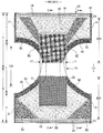
도 1은 전개 상태의 팬티 타입 일회용 기저귀의 평면도(내면 측)이다.
도 2는 전개 상태의 팬티 타입 일회용 기저귀의 평면도(외면 측)이다.
도 3은 전개 상태의 팬티 타입 일회용 기저귀의 주요부만 나타내는 평면도이다.
도 4의 (a)는 도 1의 C-C단면도, (b)는 도 1의 E-E단면도이다.
도 5는 도 1의 A-A단면도이다.
도 6은 도 1의 B-B단면도이다.
도 7은 전개 상태의 팬티 타입 일회용 기저귀에서 신축 영역의 주요부 평면도(내면 측)이다.
도 8의 (a)는 도 1의 C-C선에 대응하는 단면도, (b)는 도 1의 E-E선에 대응하는 단면도이다.
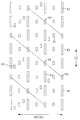
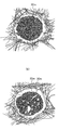
도 9는 특허문헌 1이 개시하는 접합부 배열을 나타내는 평면도 및 단면도이다.
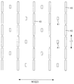
도 10은 특허문헌 2가 개시하는 접합부 배열을 나타내는 평면도이다.
도 11은 설명용 참고예로서의 접합부 배열을 나타내는 평면도이다.
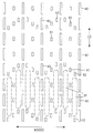
도 12는 본 발명의 접합부 배열의 제1 실시예를 나타내는 것으로서, (a)는 평면도, (b)는 B-B단면도이다.
도 13은 본 발명의 접합부 배열의 제2 실시예를 나타내는 평면도이다.
도 14는 본 발명의 접합부 배열의 제3 실시예를 나타내는 평면도이다.
도 15는 본 발명의 접합부 배열의 제4 실시예를 나타내는 평면도이다.
도 16은 본 발명의 접합부 배열의 제5 실시예를 나타내는 평면도이다.
도 17은 본 발명의 접합부 배열의 제6 실시예를 나타내는 평면도이다.
도 18은 본 발명의 접합부 배열의 제7 실시예를 나타내는 평면도이다.
도 19는 본 발명의 접합부 배열의 제8 실시예를 나타내는 평면도이다.
도 20은 본 발명의 접합부 배열의 제9 실시예를 나타내는 평면도이다.
도 21은 본 발명의 접합부 배열의 제10 실시예를 나타내는 평면도이다.
도 22는 본 발명의 접합부 배열의 제11 실시예를 나타내는 평면도이다.
도 23은 본 발명의 접합부 배열의 제12 실시예를 나타내는 평면도이다.
도 24는 본 발명의 접합부에서의 접합 형태예를 나타내는 단면도이다.
도 25는 접합 형태예를 나타내는 설명용 단면도이다.
도 26은 접합 형태예를 나타내는 평면도이다.
도 27은 신축 부재의 제조용 초음파 실링 장치의 개략도이다.1 is a plan view (inner side) of a panty-type disposable diaper in a deployed state.
Fig. 2 is a plan view (outer side) of a panty-type disposable diaper in a deployed state.
3 is a plan view showing only the main part of the panty-type disposable diaper in the deployed state.
4 (a) is a cross-sectional view taken along line CC in FIG. 1, and (b) is a cross-sectional view taken along line EE in FIG. 1.
5 is a cross-sectional view taken along line AA of FIG. 1.
6 is a cross-sectional view taken along line BB of FIG. 1.
Fig. 7 is a plan view (inner side) of a main part of an elastic region in a panty-type disposable diaper in a deployed state.
8 (a) is a cross-sectional view corresponding to the CC line in FIG. 1, and (b) is a cross-sectional view corresponding to the EE line in FIG.
9 is a plan view and a cross-sectional view showing an arrangement of joints disclosed in
10 is a plan view showing an arrangement of joints disclosed in Patent Document 2.
11 is a plan view showing an arrangement of joints as a reference example for explanation.
12 is a view showing a first embodiment of the arrangement of the junction of the present invention, (a) is a plan view, (b) is a BB cross-sectional view.
13 is a plan view showing a second embodiment of the junction arrangement of the present invention.
14 is a plan view showing a third embodiment of the arrangement of the joints of the present invention.
15 is a plan view showing a fourth embodiment of the arrangement of the joints of the present invention.
16 is a plan view showing a fifth embodiment of the arrangement of the joints of the present invention.
17 is a plan view showing a sixth embodiment of the arrangement of joints of the present invention.
18 is a plan view showing a seventh embodiment of the junction arrangement of the present invention.
19 is a plan view showing an eighth embodiment of the junction arrangement of the present invention.
20 is a plan view showing a ninth embodiment of the arrangement of joints of the present invention.
21 is a plan view showing a tenth embodiment of the arrangement of joints of the present invention.
22 is a plan view showing an eleventh embodiment of the arrangement of the joints of the present invention.
23 is a plan view showing a twelfth embodiment of an arrangement of joints of the present invention.
24 is a cross-sectional view showing an example of a bonding mode at the bonding portion of the present invention.
25 is a cross-sectional view illustrating an example of a bonding mode.
26 is a plan view showing an example of a bonding mode.
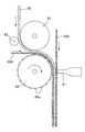
27 is a schematic view of an ultrasonic sealing device for manufacturing a stretchable member.
이하, 본 발명의 일 실시형태에 대하여 첨부 도면을 참조하면서 상세히 설명한다. 또한, 단면도 중의 점 모양 부분은 핫멜트 접착제 등의 접합 수단을 나타내고 있다.Hereinafter, one embodiment of the present invention will be described in detail with reference to the accompanying drawings. In addition, the dot-shaped portion in the sectional view shows bonding means such as a hot melt adhesive.
도 1∼도 6은 본 발명의 일회용 착용 물품의 일 예로서의 팬티 타입 일회용 기저귀를 나타내고 있다. 부호 LD(종방향)는 전후 방향을, WD는 폭 방향을 나타내고 있다.1 to 6 show a panty-type disposable diaper as an example of a disposable wearing article of the present invention. The symbol LD (longitudinal direction) indicates the front-rear direction, and WD indicates the width direction.
이 팬티 타입 일회용 기저귀(이하, 간단히 기저귀라고도 함)는, 앞몸판(F) 및 뒷몸판(B)을 구성하는 외장체(20)와, 이 외장체(20)의 내면에 고정되어 일체화된 내장체(10)를 갖고 있으며, 내장체(10)는 액 투과성 탑 시트(11)와 액 불투과성 시트(12)의 사이에 흡수체(13)가 개재되어 구성되는 것이다. 제조 시에는, 외장체(20)의 내면(상면)에 대하여 내장체(10)의 이면이 핫멜트 접착제 등의 접합 수단에 의해 접합된 후에, 내장체(10) 및 외장체(20)가 앞몸판(F) 및 뒷몸판(B)의 경계인 전후 방향(LD)(종방향)의 중앙에서 작게 접어져서, 그 양측부가 상호 열 용착 또는 핫멜트 접착제 등으로 접합되어 사이드 실링부(21)가 형성됨으로써, 웨이스트 개구 및 좌우 한 쌍의 다리 개구가 형성된 팬티 타입 일회용 기저귀가 된다.This panty-type disposable diaper (hereinafter also simply referred to as a diaper) includes an
(내장체의 구조예)(Structural example)
내장체(10)는 도 4∼도 6에 나타내는 바와 같이, 액 투과성 탑 시트(11)와, 폴리에틸렌 등으로 구성되는 액 불투과성 시트(12)의 사이에 흡수체(13)를 개재시킨 구조를 갖고 있으며, 탑 시트(11)를 투과한 배설액을 흡수 유지하는 것이다. 내장체(10)의 평면 형상은 특별히 한정되지 않지만, 도 1에 나타나는 바와 같이, 거의 직사각형으로 하는 것이 일반적이다.4 to 6, the
흡수체(13)의 겉측(피부 측)을 덮는 액 투과성 탑 시트(11)로서는, 유공 또는 무공 부직포나 다공성 플라스틱 시트 등이 적합하게 사용된다. 부직포를 구성하는 소재 섬유는 폴리에틸렌 또는 폴리프로필렌 등의 올레핀계, 폴리에스테르계, 폴리아미드계 등의 합성섬유 외에, 레이온이나 큐프라 등의 재생섬유, 면 등의 천연섬유로 할 수 있으며, 스펀 레이스법, 스펀 본드법, 써멀 본드법, 멜트 블로운법, 니들 펀치법 등 적당한 가공법으로 얻어진 부직포를 사용할 수 있다. 이들 가공법 중, 스펀 레이스법은 유연성, 드레이프성이 풍부한 점에서 우수하고, 써멀 본드법은 부피가 크고 소프트한 점에서 우수하다. 액 투과성 탑 시트(11)에 다수의 투과 구멍을 형성한 경우에는, 오줌 등이 신속하게 흡수되게 되어, 드라이 터치성이 우수한 것이 된다. 액 투과성 탑 시트(11)는 흡수체(13)의 측연부를 말아넣어 흡수체(13)의 이측까지 연재되어 있다.As the liquid-
흡수체(13)의 이측(비피부 접촉 측)을 덮는 액 불투과성 시트(12)는 폴리에틸렌 또는 폴리프로필렌 등의 액 불투과성 플라스틱 시트가 사용되지만, 최근에는 땀이 차는 것을 방지하는 측면에서 투습성을 갖는 것이 적합하게 사용된다. 이 차수·투습성 시트는 예를 들면, 폴리에틸렌이나 폴리프로필렌 등의 올레핀 수지 중에 무기 충전재를 용융 혼련하여 시트를 형성한 후, 1축 또는 2축 방향으로 연신함으로써 얻어지는 미다공성 시트이다.The liquid-
흡수체(13)로서는, 공지의 것, 예를 들면 펄프 섬유의 적섬체, 셀룰로오스 아세테이트 등의 필라멘트의 집합체, 혹은 부직포를 기본으로 하여, 필요에 따라 고흡수성 폴리머를 혼합, 고착 등 하여 구성되는 것을 사용할 수 있다. 이 흡수체(13)는 형상 및 폴리머 유지 등을 위해서, 필요에 따라 크레이프지 등의 액 투과성 및 액 유지성을 갖는 포장 시트(14)로 포장할 수 있다.As the
흡수체(13)의 형상은 고간부에 전후 양측보다 폭이 좁은 잘록 부분(13N)을 갖는 거의 모래시계형으로 형성되어 있다. 잘록 부분(13N)의 치수는 적당히 정할 수 있지만, 잘록 부분(13N)의 전후 방향 길이는 기저귀 전체 길이의 20∼50% 정도로 할 수 있고, 그 가장 좁은 부분의 폭은 흡수체(13)의 전체 폭의 40∼60% 정도로 할 수 있다. 이러한 잘록 부분(13N)을 가질 경우에, 내장체(10)의 평면 형상이 거의 직사각형으로 되어 있으면, 내장체(10)에서 흡수체(13)의 잘록 부분(13N)과 대응하는 부분에 흡수체(13)를 갖지 않는 무흡수체 측부(17)가 형성된다.The shape of the
액 불투과성 시트(12)는 액 투과성 탑 시트(11)와 함께 흡수체(13)의 폭 방향 양측에서 이측으로 되접어 꺾여 있다. 이 액 불투과성 시트(12)로서는, 배변이나 오줌 등의 갈색이 나오지 않도록 불투명한 것을 사용하는 것이 바람직하다. 불투명화로서는, 플라스틱 중에 탄산칼슘, 산화티탄, 산화아연, 화이트 카본, 클레이, 탈크, 황산바륨 등의 안료나 충전재를 내첨하여 필름화한 것이 적합하게 사용된다.The liquid-
내장체(10)의 양측부에는 다리 둘레에 피트되는 입체 개더(90)가 형성되어 있다. 이 입체 개더(90)는 도 5 및 도 6에 나타나는 바와 같이, 내장체(10)의 이면 측부에 고정된 고정부(91)와, 이 고정부(91)로부터 내장체(10)의 옆쪽을 거쳐 내장체(10)의 표면의 측부 위까지 연재하는 본체부(92)와, 본체부(92)의 전후 단부가 도복 상태에서 내장체(10)의 표면(도시한 형태에서는 탑 시트(11))의 측부에 고정되어 형성된 도복 부분(93)과, 이 도복 부분(93) 간이 비고정으로 되어 형성된 자유 부분(94)을 갖고 있다. 이들 각 부분은 부직포 등의 시트를 되접어 꺽어 이중 시트로 한 개더 시트(95)에 의해 형성되어 있다. 개더 시트(95)는 내장체(10)의 전후 방향 전체에 걸쳐 설치되어 있고, 도복 부분(93)은 무흡수체 측부(17)보다 전측 및 후측에 마련되며, 자유 부분(94)은 무흡수체 측부(17)의 전후 양측에 연재되어 있다. 또한, 이중 개더 시트(95) 사이에는 자유 부분의 선단부 등에 세장형 개더 탄성 부재(96)가 배치되어 있다. 개더 탄성 부재(96)는 제품 상태에 있어서, 도 5에 나타내는 바와 같이, 탄성 수축력에 의해 자유 부분(94)을 끌어올리기 위한 것이다.On both sides of the
도 5 및 도 6에 나타내는 형태에서는, 도복 비신축 부분(97) 이외에서는 개더 탄성 부재(96)의 위치의 핫멜트 접착제를 통해 개더 탄성 부재(96)가 개더 시트(95)에 접착 고정됨과 동시에, 개더 시트(95)의 대향면이 접합되어 있지만, 도복 비신축 부분(97)에서는, 개더 탄성 부재(96)의 위치에 핫멜트 접착제가 없으며, 따라서, 개더 탄성 부재(96)와 개더 시트(95)가 접착되어 있지 않아, 개더 탄성 부재(96)를 갖는 위치에서 개더 시트(95)의 대향면이 접합되어 있지 않은 것이다.In the form shown in FIGS. 5 and 6, the gather
도 5 및 도 6에 나타나는 입체 개더(90)는 본체부(92)가 되접어 꺾여 있지 않은 형태이다.The three-dimensional gather 90 shown in FIGS. 5 and 6 is in a form in which the
개더 탄성 부재(96)로서는, 통상 사용되는 스티렌계 고무, 올레핀계 고무, 우레탄계 고무, 에스테르계 고무, 폴리우레탄, 폴리에틸렌, 폴리스티렌, 스티렌 부타디엔, 실리콘, 폴리에스테르 등의 소재를 사용할 수 있다. 또한, 외측으로부터 잘 안보이게 하기 위해서, 굵기는 925dtex 이하, 텐션은 150∼350%, 간격은 7.0㎜ 이하로 하여 배치하는 것이 좋다. 또한, 개더 탄성 부재(96)로서는, 도시한 형태와 같은 실 모양 외에, 어느 정도의 폭을 갖는 테이프형인 것을 사용할 수도 있다.As the gather
상술한 개더 시트(95)를 구성하는 소재 섬유도 액 투과성 탑 시트(11)와 마찬가지로, 폴리에틸렌 또는 폴리프로필렌 등의 올레핀계, 폴리에스테르계, 폴리아미드계 등의 합성섬유 외에, 레이온이나 큐프라 등의 재생섬유, 면 등의 천연섬유로 할 수 있으며, 스펀 본드법, 써멀 본드법, 멜트 블로운법, 니들 펀치법 등 적당한 가공방법으로 얻어진 부직포를 사용할 수 있지만, 특히나 땀이 차는 것을 방지하기 위해 평량을 억제하여 통기성이 우수한 부직포를 사용하는 것이 좋다. 더욱이, 개더 시트(95)에 대해서는, 오줌 등의 투과를 방지함과 동시에, 발진을 방지하면서 피부에의 감촉성(드라이감)을 높이기 위해 실리콘계, 파라핀 금속계, 알킬 크로믹 클로라이드계 발수제 등을 코팅한 발수 처리 부직포를 사용하는 것이 바람직하다.Similar to the liquid-
도 3∼도 6에 나타내는 바와 같이, 내장체(10)는 그 이면이 내외 고정 영역(10B)(사선 영역)에서, 외장체(20)의 내면에 대하여 핫멜트 접착제 등으로 접합된다. 이 내외 고정 영역(10B)은 적당히 정할 수 있어, 내장체(10)의 폭 방향(WD)의 거의 전체로 할 수도 있지만, 폭 방향 양단부는 외장체(20)에 고정시키지 않는 것이 바람직하다.3 to 6, the inner surface of the
(외장체의 구조예)(Structure example of exterior body)
외장체(20)는 흡수체(13)의 측연보다 바깥쪽에 연재되어 있다. 외장체(20)는 도시한 형태와 같이, 고간부에서 외장체(20)의 측연이 내장체(10)의 측연보다 폭 방향 중앙 측에 위치하고 있어도, 또한 폭 방향 외측에 위치하고 있어도 좋다. 또한, 외장체(20)는 사이드 실링부(21)와 대응하는 전후 방향 범위인 몸통 둘레부(T)와, 앞몸판(F)의 몸통 둘레부(T) 및 뒷몸판(B)의 몸통 둘레부(T) 사이의 전후 방향 범위인 중간부(L)를 갖는다.The
그리고, 도시한 형태의 외장체(20)에서는, 그 중간부(L)의 전후 방향 중간을 제외하고, 도 2 및 도 4∼도 6에 나타나는 바와 같이, 제1 시트층(20A) 및 제2 시트층(20B)의 사이에 탄성 시트, 예를 들면, 탄성 필름(30)이 개재됨과 동시에, 도 9에 나타나는 바와 같이, 제1 시트층(20A) 및 제2 시트층(20B)이 간격을 두고 배열된 다수의 시트 접합부(40)에서 탄성 필름(30)을 관통하는 접합 구멍(31)을 통해 접합된 탄성 시트 신축 구조(20X)를 갖고 있다.In addition, in the illustrated
상기 기저귀에의 적용 형태에서는, 탄성 시트(도 9의 예에서는 탄성 필름(30))의 신축 방향(ED)은 기저귀의 폭 방향(WD)으로 되어 있다.In the application form to the diaper, the stretching direction ED of the elastic sheet (the
제1 시트층(20A) 및 제2 시트층(20B)은 탄성 필름(30)의 접합 구멍(31)을 통해서가 아니라, 탄성 필름(30)을 통해 간접적으로 접합되어 있어도 좋다. 외장체(20)의 평면 형상은 중간부(L)의 폭 방향 양 측연이 각각 개구를 형성하도록 오목형 다리 둘레 라인(29)에 의해 형성되어 있으며, 전체적으로 모래시계를 닮은 형상을 이루고 있다. 외장체(20)는 앞몸판(F) 및 뒷몸판(B)에서 개별적으로 형성하여, 양자가 고간부에서 기저귀의 전후 방향(LD)으로 이간하도록 배치해도 좋다.The
도 1 및 도 2에 나타내는 형태는, 탄성 시트 신축 구조(20X)가 웨이스트 단부(23)까지 연재되어 있는 형태이지만, 웨이스트 단부(23)에 탄성 시트 신축 구조(20X)를 사용하면, 웨이스트 단부(23)의 조임이 불충분해지는 등, 필요에 따라, 도 7 및 도 8에 나타내는 바와 같이, 웨이스트 단부(23)에는 탄성 시트 신축 구조(20X)를 마련하지 않고, 종래의 세장형 웨이스트부 탄성 부재(24)에 의한 신축 구조를 마련할 수도 있다. 웨이스트부 탄성 부재(24)는 전후 방향(LD)으로 간격을 두고 배치된 복수의 실고무 등의 세장형 탄성 부재로서, 신체의 몸통 둘레를 조이도록 신축력을 주는 것이다. 웨이스트부 탄성 부재(24)는 간격을 조밀하게 하여 실질적으로 한 묶음으로서 배치되는 것이 아니라, 소정의 신축 존을 형성하도록 전후 방향으로 3∼8㎜ 정도의 간격을 두고 3개 이상, 바람직하게는 5개 이상 배치된다. 웨이스트부 탄성 부재(24)의 고정 시의 신장율은 적당히 정할 수 있지만, 통상의 성인용인 경우, 230∼320% 정도로 할 수 있다. 웨이스트부 탄성 부재(24)는 도시한 예에서는 실고무를 사용하였지만, 예를 들면 평고무 등, 다른 세장형 신축 부재를 사용해도 좋다. 도시하지 않지만, 웨이스트 단부(23)에 탄성 필름(30)을 마련함과 동시에, 탄성 필름(30)과 겹치는 위치에 세장형 웨이스트부 탄성 부재(24)를 마련하여, 양쪽 탄성 부재에 의한 신축 구조로 할 수도 있다. 또한, 도시한 형태에서는, 외장체(20)에서 다리 개구의 테두리 부분에는 다리 개구를 따라 연장되는 세장형 탄성 부재는 마련되어 있지 않지만, 해당 테두리 부분에서 탄성 필름(30)과 겹치는 위치에, 또는 해당 테두리 부분의 탄성 필름(30) 대신 세장형 탄성 부재를 마련할 수도 있다.1 and 2, the elastic
다른 형태로서는, 도시하지 않지만, 앞몸판(F)의 몸통 둘레부(T)와 뒷몸판(B)의 몸통 둘레부(T) 사이의 중간부(L)에는 탄성 시트 신축 구조(20X)를 마련하지 않는 형태로 하거나, 앞몸판(F)의 몸통 둘레부(T) 내부터 중간부(L)를 거쳐 뒷몸판(B)의 몸통 둘레부(T) 내까지 전후 방향(LD)으로 연속적으로 탄성 시트 신축 구조(20X)를 마련하거나, 앞몸판(F) 및 뒷몸판(B) 중 어느 한쪽에만 탄성 시트 신축 구조(20X)를 마련하거나 하는 등, 적당한 변형도 가능하다.As another form, although not shown, an elastic sheet
(접합부의 형태)(Type of joint)
본 발명에서는, 접합부의 배치에 특징을 갖는다. 이 특징을 분명히 하기 위해서, 종래예의 접합부의 배치에 대해서 구체적으로 설명해둔다.In the present invention, the arrangement of the joints is characterized. In order to clarify this characteristic, the arrangement | positioning of the junction part of a prior art example is demonstrated concretely.
도 9는 특허문헌 1에 대표예로서 나타난 것이다.9 is a representative example in
즉, 접합부(40)군은 지그재그형 배열이 되고, 접합부(40)는 신축 방향과 직교하는 방향으로 가늘고 길면서 신축 방향의 중앙을 지나는 중앙선에 관하여 선 대칭(도 9의 (a)에서 좌우 대칭)인 형상으로 되어 있으며, 접합부(40)의 신축 방향의 폭(40x)은 바람직하게는 0.2∼0.4㎜가 되고, 신축 방향으로 나열되는 접합부(40)의 간격(d1)은 3∼12.9㎜, 보다 바람직하게는 5∼6.4㎜가 되고, 신축 방향과 직교하는 방향으로 나열되는 접합부(40)의 간격(d2)은 2∼10.5㎜, 보다 바람직하게는 2.3∼4.6㎜가 된 것이다.That is, the group of
이와 같이, 신축 방향의 폭(40x)이 현저히 좁은 접합부(40)가, 신축 방향으로 어느 정도 넓은 이간 간격(d1)으로 지그재그형으로 배열됨과 동시에, 탄성 필름(30)의 수축력이 각 접합부(40)에 대하여 직접적으로 작용하여, 탄성 필름(30)의 접합 구멍(31)의 위치에 각 접합부(40)의 배치·간격이 제대로 유지되는 결과, 유연성이 저하되기 어렵다. 또한, 주름(25f)이 신축 방향과 직교하는 방향을 따라 대부분 곧바로 연장되고 게다가, 그 주름(25f)과 주름(25f)의 사이에 접합부(40)가 가려져서 눈에 띄지 않게 된다. 따라서, 유연성 저하를 억제하면서, 보다 옷감에 가까운 외관의 탄성 시트 신축 구조(20X)가 된다.As described above, the joining
이에 대하여 접합부(40)의 배열은 지그재그형 배열이지만, 접합부(40)의 형상을 원형으로 하면, 주름의 주름(25f)과 주름(25f)의 사이에 접합부(40)가 뚜렷하게 시인될 뿐만 아니라, 주름(25f)이 접합부(40)를 크게 돌아 들어가도록 하여 신축 방향과 직교하는 방향으로 신장하기 때문에, 전체적으로 파선형 주름(25f)이 형성되어, 옷감과 같은 외관을 얻지 못하는 경향이 있다.On the other hand, the arrangement of the
이러한 관점에서, 접합부(40)의 형상은 신축 방향과 직교하는 방향으로 가늘고 긴 것이 바람직하다. 그런데, 접합부(40)의 신축 방향과 직교하는 방향의 최대 길이가 너무 짧거나 너무 길거나 하면, 주름(25f)의 직선성이 저하되거나 유연성이 저하되거나 할 우려가 있다. 따라서, 이들 치수는 적당히 정할 수 있지만, 접합부(40)의 신축 방향과 직교하는 방향의 길이(40y)는 0.4∼3.2㎜, 특히 0.7∼1.4㎜인 것이 바람직하다고 여겨지고 있다.From this viewpoint, it is preferable that the shape of the
한편, 특허문헌 2에서는, 도 10의 (a), (b)에 나타내는 두 예 모두, 신축성 필름의 개구부(약간 종으로 긴 직사각형으로 도시되어 있음)의 배열은 마찬가지로 지그재그형 배열이며, (b)의 예에서는 작은 원형의 부접합부가 직사각형의 주개구부 간에 배치되어 있는 것이다. (b)의 예에서도 지그재그형 배열 사상에 근거하는 것이다.On the other hand, in Patent Document 2, in both of the examples shown in Figs. 10A and 10B, the arrangement of the openings of the stretchable film (shown as a long rectangle with a slight bell) is similarly a zigzag arrangement, and (b) In the example, a small circular sub-joint is arranged between the rectangular main openings. The example in (b) is also based on the zigzag arrangement idea.
그리고, 각 개구부의 배치 및 치수는 도 10에 기재한 치수 범위(단위는 ㎜임)인 것이 주로 외관, 촉감 및 통기성 등의 점이 바람직하다고 여기고 있다.In addition, it is considered that the arrangement and dimensions of each opening are preferably in the dimensional range (unit is mm) described in FIG. 10, preferably in terms of appearance, touch, and breathability.
특허문헌 1 및 2의 양 발명은 종으로 긴 개구부를 개시함과 동시에, 지그재그형 배치를 개시하고 있다.Both inventions of
그러나, 종래예에서는, 신축 방향과 직교하는 방향의 탄성 필름의 개구부 간의 이간 간격이 크게 설정되어 있기 때문에, 신축 방향의 신축 응력이 높아, 예를 들면, 팬티형 일회용 기저귀에 적용한 경우에 과도하게(폭 방향으로) 강하게 조이게 된다고 느끼는 착용자도 많이 존재한다.However, in the conventional example, since the spacing between the openings of the elastic films in the direction perpendicular to the stretching direction is large, the stretching stress in the stretching direction is high, for example, excessive (width) when applied to a panty-type disposable diaper. There are also many wearers who feel that they are tightening strongly.
여기서, 개구부 길이(B)가 0.3∼0.7㎜, 이간 간격(H)이 0.6∼1.4㎜로 되어 있지만, 이것을 본 발명과 관련되는,Here, although the opening length B is 0.3 to 0.7 mm, and the spacing H is 0.6 to 1.4 mm, this relates to the present invention.
(인접하는 제1 접합부 간의 이간 거리)/(접합부의 일점부터 인접하는 제1 접합부가 대응하는 일점까지의 거리)의 백분율을 계산해 보면, (0.3∼0.7㎜)/(0.6∼1.4㎜)=21.4∼183%로, 계산상의 하한치는 작지만, 현실적으로는 큰 값을 상정하고 있는 것이라고 생각된다.When calculating the percentage of (distance between adjacent first joints) / (distance from one point of the joint to the corresponding one of the adjacent first joints), (0.3 to 0.7 mm) / (0.6 to 1.4 mm) = 21.4 It is considered that the lower limit of calculation is small at -183%, but in reality, a large value is assumed.
이에 대하여, 본 발명자는 도 11에 나타내는 바와 같이, 신축 방향과 직교하는 방향(도면에서는 상하 방향: 부호 LD의 방향)의 탄성 필름의 개구부 간의 이간 간격을 작게 설정하면 신축 방향의 신축 응력을 작게 할 수 있으며, 이로써, 팬티형 일회용 기저귀에 적용한 경우에 약한 조임력에 의해 착용자에 대하여 쉽게 피트시키는 것이 가능하다는 것을 알았다.On the other hand, as shown in Fig. 11, the present inventor can reduce the stretching stress in the stretching direction by setting the separation distance between the openings of the elastic films in the direction orthogonal to the stretching direction (upward and downward directions in the drawing: the direction of the sign LD). It has been found that, when applied to a panty-type disposable diaper, it is possible to easily fit the wearer by a weak tightening force.
이 이유는 개구부는 외부로부터의 폭 방향(탄성 필름의 신축 방향)으로 작은 신장력을 주는 것만으로, 도 9와 같이 폭 방향으로 개구하여 접합 구멍(31)이 되는데 비하여, 개구부 간의 신축 방향과 직교하는 이간 간격 영역에서는, 폭 방향으로 신장시켰다 하더라도 개구부는 존재하지 않기 때문에, 탄성 필름의 신장 응력이 그대로 수축력이 되어 착용자를 조이게 되기 때문이라고 생각된다.The reason is that the opening only gives a small stretching force in the width direction (extension direction of the elastic film) from the outside, and opens in the width direction as shown in Fig. 9 to become the joining
도 11에 나타내는 형태는 착용자에 대하여 쉽게 피트시킬 수 있는 것 외에, 접합부가 차지하는 면적율, 폭 방향으로 신장한 사용 상태에서는 접합 구멍이 차지하는 면적율이 높아지므로 통기성이 우수하다는 이점도 초래된다.In addition to being easily fit to the wearer in the form shown in FIG. 11, the area ratio occupied by the joint portion and the area ratio occupied by the joint hole are increased in the use state extended in the width direction, which also leads to an advantage of excellent breathability.
그러나, 도 11의 (a)에 나타내는 형태인 제품에서의 사용 형태에서는, 직교 방향(LD)을 따른 접합부(40, 40…)의 열과, 이것과 신축 방향(ED)(폭 방향)으로 이간하는 인접하는 접합부(40, 40…)의 열과의 이간 영역에 직교 방향(LD)을 따른 주름이 형성된다. 이 주름(25F)은 도 11의 (b)에 나타내는 바와 같이, 단지 똑같은 산 형상이다. 즉, 특허문헌 1에 나타나며, 여기에 도 9의 (c)에 나타내는 횡단면과 다르다.However, in the form of use in a product which is the form shown in Fig. 11 (a), the rows of the
도 11에 나타내는 형태를 제품의 신축 영역 전체적으로 디자인 관점에서 보았을 때, 직교 방향(LD)으로 긴 주름(25F)이 신축 방향(ED)(폭 방향)으로 똑같은 반복으로 형성되어 있을 뿐, 자칫하면 단순한 디자인이고, 상품의 어필성이 부족한 것이 된다.When the shape shown in FIG. 11 is viewed from a design point of view as a whole of the elastic region of the product, the
본 발명은 제1 접합부 및 제2 접합부를 갖고, 구체적으로는 특허청구범위에 기재된 구성으로서, 각종 형태를 포함하고, 또한, 각종 형태의 조합도 포함하는 것이다.This invention has a 1st bonding part and a 2nd bonding part, Specifically, as a structure as described in a claim, it includes various forms, and also the combination of various forms.
지면의 형편상, 이하, 대표예에 대해서 차례로 설명한다.For convenience of the paper, a representative example will be described below in order.
<제1 실시예><First Example>
도 12에 나타내는 제1 실시예와 관련되는 신축 부재에서는, 통기성을 갖는 제1 시트층 및 통기성을 갖는 제2 시트층의 사이에 탄성 시트가 개재되고, 상기 제1 시트층 및 제2 시트층이 간격을 두고 배열된 다수의 시트 접합부에서, 탄성 시트를 관통하는 접합 구멍을 통해 또는 상기 탄성 시트를 통해 접합된 탄성 시트 신축 구조를 구비하고 있다.In the elastic member according to the first embodiment shown in Fig. 12, an elastic sheet is interposed between the first sheet layer having air permeability and the second sheet layer having air permeability, and the first sheet layer and the second sheet layer are interposed. In a plurality of sheet joints arranged at intervals, an elastic sheet expansion and contraction structure joined through a bonding hole penetrating through the elastic sheet or through the elastic sheet is provided.
또한, 상기 탄성 시트 신축 구조를 나타내는 신축 영역은 상기 탄성 시트의 수축력에 의해 신축 방향으로 신축 가능하다.In addition, the stretchable region showing the elastic sheet stretchable structure is stretchable in the stretchable direction by the shrinking force of the elastic sheet.
본 발명에서는, 상기 접합부는 제1 접합부(40, 40…) 외에, 제2 접합부(41, 41…)를 갖는다.In the present invention, the joining portion has second joining
제1 접합부(40, 40…)는 직교 방향(LD)을 따라 간격을 두고 배열되며, 제1 접합부 열이 형성되어 있다.The first joining
나중에 예를 들면 제8 실시예로서 도 19에 의해 설명하는 바와 같이, 제1 접합부(40, 40…)열은 직교 방향(LD)을 따르지 않고, 신축 방향(ED)과 교차하는 각도(θ)가 45도∼135도의 범위에서 경사져 있어도 된다.As will be explained later by, for example, FIG. 19 as an eighth embodiment, the first joining
제1 실시예에서는 교차하는 각도(θ)가 90도인 예이다.In the first embodiment, the intersecting angle θ is an example of 90 degrees.
제1 접합부(40)는 직교 방향 기준의 길이(L)가 0.3∼7.0㎜, 바람직하게는 0.5∼5.0㎜, 특히 바람직하게는 0.7∼2.5㎜로 형성된다.The first joining
또한, 제1 접합부(40, 40…)열은 신축 방향(ED) 기준의 형성 피치(S0)가 2.0∼20.0㎜, 바람직하게는 3.0∼15.0㎜, 특히 바람직하게는 4.0∼10.0㎜로 형성된다.In addition, the rows of the first joining
더욱이, 제1 접합부(40, 40…)열에서 인접하는 제1 접합부(40, 40) 상호 관계가 정하는 직교 방향(LD) 기준에서의 거리로서,Moreover, as the distance in the orthogonal direction (LD) reference determined by the mutual relationship between the adjacent
(인접하는 제1 접합부 간의 이간 거리(d))/(접합부의 일점부터 인접하는 제1 접합부가 대응하는 일점까지의 거리(P))의 비율의 백분율(R)이 5∼60%, 바람직하게는 10∼45%, 특히 바람직하게는 20∼35%가 된다.The percentage (R) of the ratio of (distance (d) between adjacent first junctions) / (distance (P) from one point of the junction to the corresponding one of the adjacent first junctions) is 5 to 60%, preferably Is 10 to 45%, particularly preferably 20 to 35%.
이 백분율이 과도하게 높으면, 제품에 적용했을 경우, 폭 방향(신축 방향)의 신축 응력이 높아 착용 물품으로서 적절한 피트성을 얻기 어렵다.When this percentage is excessively high, when applied to a product, the stretching stress in the width direction (stretching direction) is high, and it is difficult to obtain appropriate fit properties as a worn article.
또한, 백분율이 과도하게 낮으면, 직교 방향(LD)으로 인접하는 제1 접합부(40, 40) 상호가 제조 과정에서 연속화될 가능성을 배제할 수 없음과 동시에, 보다 근본적으로는, 접합부를 형성하는 앤빌 및 가열 혼에 과도하게 설비적 부담이 가, 안정 조업을 저해하게 된다.In addition, if the percentage is excessively low, it is impossible to exclude the possibility that the
제2 접합부(41, 41)열 내에는 제1 접합부(40)의 길이(L) 및 그 이상의 길이의 접합부는 형성되어 있지 않은 것이 바람직하다. 이 관점에서도, 도 10의 양태와는 완전히 다른 것이다.It is preferable that the length L of the
상기 제1 실시예에서는, 대표적으로 다음의 이점 또는 특징을 나타내는 것이 된다.In the first embodiment, representatively, the following advantages or characteristics are exhibited.
(1) 상기 백분율(R)이 낮기 때문에, 신축 방향의 신축 응력이 낮아, 유연한 신장을 가진 신축 시트 부재가 되며, 이것을 흡수성 물품에 적용했을 경우에 착용감이 우수한 것이 된다.(1) Since the above-mentioned percentage (R) is low, the stretching stress in the stretching direction is low, which makes the elastic sheet member having a flexible elongation, and when this is applied to an absorbent article, it becomes excellent in wearing comfort.
게다가, 개구율이 높아지기 때문에, 통기성이 높아진다.Moreover, since the aperture ratio is increased, breathability is increased.
(2) 제1 접합부(40, 40…)열 뿐만 아니라, 제2 접합부(41, 41…)열이 형성되어 있기 때문에, 제1 접합부(40, 40…)열과 제2 접합부(41, 41…)열의 사이에 열간 플리츠(R)를 형성할 수 있다.(2) Since not only the rows of the
(3) 제2 접합부(41)는 제1 접합부(40)보다 작은 면적을 나타내기 때문에, 모양형인 것으로 보인다.(3) Since the second joining
(4) 제1 접합부(40, 40…)열과 제2 접합부(41, 41…)열의 사이에 열간 플리츠(R)를 형성할 수 있는 것은 제1 접합부(40, 40…)열과 제1 접합부(40, 40…)열의 사이에 2개의 열간 플리츠를 형성할 수 있는 것을 의미한다. 그렇지만, 제2 접합부(41, 41…)열에서는 제2 접합부(41, 41) 상호의 간격이 길기 때문에, 앤빌 및 가열 혼에 과도하게 설비적 부담이 가지 않고 플리츠를 형성할 수 있는 것을 의미한다. 그 결과, 도 11과 같이, 제1 접합부(40, 40…)열만으로 열간 플리츠를 형성하는 경우와 비교하여, 단위면적당 가는 폭으로 다수의 플리츠를 설비 부담을 주지 않고 형성할 수 있다.(4) What can form the hot pleats R between the 1st row of
이렇게 하여, 착용자의 피부에 대한 접촉 면적이 저감되어, 쾌적성 향상과 부드러움 향상을 도모할 수 있다.In this way, the contact area of the wearer's skin is reduced, thereby improving comfort and improving softness.
<제2 실시예><Second Example>
도 13에 나타내는 바와 같이, 제2 접합부(41, 41…)군을 제1 접합부(40, 40)의 직교 방향(LD)의 상호 간에 배치할 수 있다. 이 경우, 제1 접합부(40)의 길이(L)가 짧아도, 제2 접합부(41)가 위치함으로써, 신축 응력을 저감시킬 수 있다.As shown in FIG. 13, the
<제3 실시예><Example 3>
도 14에 나타내는 바와 같이, 제2 접합부(41)는 제1 접합부(40)에 대하여 1대 1로 인접시키는 것이 아니라, 예를 들면, 2개의 제1 접합부(40, 40)에 대하여 1개의 제2 접합부(41)를 인접 배치하는 형태로 할 수 있다.As shown in FIG. 14, the
<제4 실시예><Fourth Example>
도 15에 나타내는 바와 같이, 제1 접합부(40, 40…)열과 제2 접합부(41, 41…)열의 사이에, 직교 방향(LD)의 이간 간격이 긴 제3 접합부(42, 42…)열을 형성할 수 있다.As shown in Fig. 15, between the first and second
제3 접합부(42)의 형성에 의해, 제1 실시예에서 나타낸 열간 플리츠(R)를, 직교 방향(LD)으로 분단한 대플리츠(bf)를 형성할 수 있다.By forming the
제3 접합부(42)와 제1 접합부(40, 40…)열의 사이에 소플리츠(sf)를 형성할 수 있다.The pleats sf can be formed between the 3rd joining
열간 플리츠(R)가 분단한 플리츠군은 신축 부재의 굽힘 강성이 낮아(구부러지기 쉬워), 신체의 움직임에 대한 추종성이 양호한 것이 된다.The pleated group in which the hot pleats R are divided is low in bending stiffness of the elastic member (easy to bend), so that the followability to the movement of the body is good.
<제5 실시예><Example 5>
도 16에 나타내는 바와 같이, 제3 접합부(42)의 위치를 제2 접합부(41)과 함께 비스듬히 배열함으로써, 비스듬한 배열의 대플리츠(bf)군을 형성할 수 있어, 디자인성이 높은 것이 된다.As shown in Fig. 16, by arranging the positions of the third joining
<제6 실시예><Example 6>
도 17에 나타내는 바와 같이, 제1 접합부(40, 40…)열에 제4 접합부(43)를 삽입 배치할 수 있다. 이 경우, 제4 접합부(43, 43…)군은 신축 방향(ED)을 따르는 것 외에, 도시한 바와 같이, 비스듬한 배치로 할 수 있다. 이 경우, 제4 접합부(43)의 면적은 제1 접합부(40) 면적의 5% 이상이고 50% 이하가 바람직하다.As shown in FIG. 17, the
<제7 실시예><Example 7>
도 18에 나타내는 바와 같이, 제1 접합부(40) 자체가 경사져 있어도 된다. 제2 접합부(42)도 경사져 있어도 된다.18, the
본 발명에서는, 접합부 길이는 직교 방향(LD)을 기준으로 하기 때문에, 도 18에 나타내는 바와 같이, 제1 접합부(40)의 길이(L)는 한 변의 중앙부터 다른 변의 중앙부까지의 직교 방향(LD) 길이가 접합부 길이가 된다.In the present invention, since the length of the joint is based on the orthogonal direction LD, as shown in FIG. 18, the length L of the first joint 40 is the orthogonal direction LD from the center of one side to the center of the other side ) Length is the length of the joint.
이간 간격도 변의 중앙과 대향하는 변의 중앙과의 직교 방향(LD) 거리가 이간 거리(d)가 된다.The distance between the centers of the sides and the orthogonal direction (LD) between the centers of the opposite sides becomes the separation distance (d).
<제8 실시예><Example 8>
도 19에 나타내는 바와 같이, 제1 접합부(40) 및 제2 접합부(42)가 모두 경사져 있어, 각 접합부의 열은 직교 방향(LD)을 따르지 않고, 신축 방향(ED)과 교차하는 각도(θ)가 45도∼135도의 범위에서 경사져 있는 예를 나타내고 있다. 교차하는 각도(θ)는 바람직하게는 50도∼130도, 특히 바람직하게는 60도∼120도이다.As shown in FIG. 19, both the
이 접합부 열이, 직교 방향(LD)을 따르지 않고, 신축 방향(ED)과 교차하여 경사져 있는 이점은, 도 18에 나타내는 제7 실시예를 비교하면 분명해진다. 즉, 도 19에 나타내는 예에서는, 직교 방향(LD) 선상에 대한, 예를 들면 제1 접합부(40, 40) 간의 이간 간격이, 도 18에 나타내는 제7 실시예보다 꽤 큰 것이 이점을 초래하는 원인이다.The advantage that this junction row does not follow the orthogonal direction LD and is inclined crossing the stretching direction ED becomes apparent when comparing the seventh embodiment shown in FIG. 18. That is, in the example shown in Fig. 19, it is advantageous that the separation between the
즉, 예를 들면, 시트 접합부(40)에서 제1 시트층(20A) 및 제2 시트층(20B)의 접합은 히트 실링이나 초음파 실링 등의 소재 용착에 의한 접합 수단에 의해 이루어지는 것이 바람직하다.That is, for example, the bonding of the
연속 생산인 경우에는, 앤빌 롤과 초음파 혼의 사이에 초음파에 의한 실링 용융을 실시하지만, 에너지 로스를 막기 위해서, 앤빌 롤의 축선 방향 전체에 시트에 대하여 초음파 혼도 밀접되어 있는 것이 중요해지지만, 이 때문에 선 접촉하는 모선을 따라 도 12의 접합부(40, 40…)열과 같이 앤빌 롤 볼록부 비율이 큰 패턴을 형성할 경우에는 큰 초음파 출력을 낼 필요가 있으며, 이를 위해 선 접촉하는 모선을 따라 과대한 밀접력을 작용시키는 것에서는 설비측 부담이 크다.In the case of continuous production, although sealing melting by ultrasonic waves is performed between the anvil roll and the ultrasonic horn, it is important that the ultrasonic horn is also close to the sheet in the entire axial direction of the anvil roll to prevent energy loss. When a pattern having a large anvil roll convex portion ratio is formed, such as a row of
이에 대하여, 도 19에 나타내는 제8 실시예의 경우(일반적으로 경사 배치인 경우)에는, 직교 방향(LD)의 선상에 위치하는 접합부가 차지하는 비율이 작아져, 안정된 선압이 되므로, 설비 부담은 작아져, 안정 조업이 가능하다.On the other hand, in the case of the eighth embodiment shown in Fig. 19 (generally in the case of inclined arrangement), the proportion occupied by the joints located on the line in the orthogonal direction LD decreases, resulting in a stable line pressure, so that the equipment burden is reduced. , Stable operation is possible.
도 19에 나타내는 제8 실시예에서는, 제1 접합부(40)(및 제2 접합부(42))가 경사져 있기 때문에) 디자인성이 우수한 주름 및 플리츠를 형성할 수 있는 이점도 함께 갖고 있다.In the eighth embodiment shown in Fig. 19, the first joining portion 40 (and the second joining
<제9 실시예><Example 9>
도 20에 나타내는 제9 실시예는 제1 접합부(40, 40…)열 및 제2 접합부(41, 41…)열을 신축 방향 ED 방향으로 치우치는 파형 곡선을 따르는 양태로 한 것이다.The ninth embodiment shown in Fig. 20 is a mode in which the rows of the first joining
파형 곡선의 배열은 미관이 우수한 것이 된다.The arrangement of the waveform curve is excellent in aesthetics.
<제10 실시예><Example 10>
도 21에 나타내는 제10 실시예는 대플리츠(bf)가 직교 방향(LD)으로 치우치는 파형 곡선을 따르는 양태로 한 것이다. 이 파형 곡선의 배열도 미관이 우수한 것이 된다.The tenth embodiment shown in FIG. 21 is such that the pleats bf follow a waveform curve biased in the orthogonal direction LD. The arrangement of the waveform curve is also excellent.
<제11 실시예><Eleventh Example>
도 22에 나타내는 제11 실시예는 제1 접합부(40, 40…)열 및 제2 접합부(41, 41…)열을 신축 방향 ED 방향으로 치우치는 파형 곡선을 따름과 동시에, 경사지는 대플리츠(bf)가 직교 방향(LD)으로 치우치는 파형 곡선을 따르는 양태로 한 것이다. 이 파형 곡선의 배열은 복잡한 플리츠 형성이 가능하며, 미관이 우수한 것이 된다.The eleventh embodiment shown in FIG. 22 follows a waveform curve that biases the
추가로, 본 발명의 실시형태를 설명한다.In addition, embodiments of the present invention will be described.
개개의 시트 접합부(40) 및 접합 구멍(31)의 자연 길이 상태에서의 형상은 기술한 직사각형 외에 적당히 정할 수 있다. 예를 들면, 도 23에 일 예를 나타내는 바와 같이, 볼록렌즈형(도 23의 (a) 참조), 마름모형(도 23의 (b) 참조), 오목렌즈형(도 23의 (c) 참조), 타원형(도 23의 (d) 참조) 외에, 진원형, 삼각형, 다각형 혹은 별 모양, 구름 모양 등, 임의의 형상으로 할 수 있다.The shape of the individual
접합 구멍(31)은 주로 접합부(40, 41, 42, 43)의 형상과, 제조 단계 또는 신축 정도와 관계된다.The joining
시트 접합부(40)에서 제1 시트층(20A) 및 제2 시트층(20B)의 접합은 탄성 필름(30)에 형성된 접합 구멍(31)을 통해 접합되는 경우, 적어도 시트 접합부(40)에서 제1 시트층(20A) 및 제2 시트층(20B) 간 이외에서는, 제1 시트층(20A) 및 제2 시트층(20B)은 탄성 필름(30)과 접합되어 있지 않은 것이 바람직하다.When the bonding of the
시트 접합부(40)에서 제1 시트층(20A) 및 제2 시트층(20B)의 접합 수단은 특별히 한정되지 않는다. 예를 들면, 시트 접합부(40)에서 제1 시트층(20A) 및 제2 시트층(20B)의 접합은 핫멜트 접착제에 의해 이루어져 있어도, 히트 실링이나 초음파 실링 등의 소재 용착에 의한 접합 수단에 의해 이루어져 있어도 좋다.The bonding means of the
시트 접합부(40)에서 제1 시트층(20A) 및 제2 시트층(20B)이 탄성 필름(30)의 접합 구멍(31)을 통해 접합되는 경우, 시트 접합부(40)가 소재 용착에 의해 형성되는 형태는 시트 접합부(40)에서 제1 시트층(20A) 및 제2 시트층(20B) 중 적어도 한쪽의 대부분 또는 일부의 용융 고체화물(20m)만으로 제1 시트층(20A) 및 제2 시트층(20B)이 접합되는 제1 용착 형태(도 24의 (a) 참조), 시트 접합부(40)에서 탄성 필름(30)의 전부 혹은 대부분 또는 일부의 용융 고체화물(30m)만으로 제1 시트층(20A) 및 제2 시트층(20B)이 접합되는 제2 용착 형태(도 24의 (b) 참조) 및 이들 양자가 조합된 제3 용착 형태(도 24의 (c) 참조) 중 어느 하나여도 좋지만, 제2, 제3 용착 형태가 바람직하다.When the
특히 바람직한 것은, 제1 시트층(20A) 및 제2 시트층(20B)의 일부 용융 고체화물(20m)과, 시트 접합부(40)에서 탄성 필름(30)의 전부 혹은 대부분의 용융 고체화물(30m)에 의해 제1 시트층(20A) 및 제2 시트층(20B)이 접합되는 형태이다. 또한, 도 26의 (b)에 나타나는 제3 용착 형태에서는, 흑색으로 비치고 있는 제1 시트층(20A) 또는 제2 시트층(20B)의 섬유 용융 고체화물(20m) 간에, 백색으로 비치고 있는 탄성 필름(30)의 용융 고체화물(30m)이 보이는데 대하여, 도 26의 (a)에 나타나는 제1 용착 형태에서는, 제1 시트층(20A) 또는 제2 시트층(20B)의 섬유 용융 고체화물(20m) 간에 탄성 필름의 용융 고체화물은 보이지 않는다.Particularly preferred are some of the
제1 접착 형태나 제3 접착 형태와 같이, 제1 시트층(20A) 및 제2 시트층(20B) 중 적어도 한쪽의 대부분 또는 일부의 용융 고체화물(20m)을 접착제로 하여 제1 시트층(20A) 및 제2 시트층(20B)을 접합할 경우, 제1 시트층(20A) 및 제2 시트층(20B)의 일부는 용융하지 않는 편이 시트 접합부(40)가 경질화되지 않기 때문에 바람직하다.Like the first adhesive form or the third adhesive form, the first sheet layer (20 m) of at least one of the
또한, 제1 시트층(20A) 및 제2 시트층(20B)이 부직포일 때에는, 제1 시트층(20A) 및 제2 시트층(20B)의 일부가 용융하지 않는 것에는, 시트 접합부(40)의 전섬유에 대해서 심(芯)(복합섬유에서의 심 뿐만 아니라 단성분 섬유의 중심 부분을 포함함)은 남지만, 그 주위 부분(복합섬유에서의 초 뿐만 아니라 단성분 섬유의 표층 측 부분을 포함함)은 용융하는 형태나, 일부 섬유는 전혀 용융하지 않지만, 나머지 섬유는 전부가 용융하거나 또는 심은 남지만, 그 주위 부분은 용융하는 형태를 포함한다.In addition, when the
제2 용착 형태 및 제3 용착 형태와 같이, 탄성 필름(30)의 용융 고체화물(30m)을 접착제로 하여 제1 시트층(20A) 및 제2 시트층(20B)을 접합하면, 박리 강도가 높은 것이 된다. 제2 용착 형태에서는, 제1 시트층(20A) 및 제2 시트층(20B) 중 적어도 한쪽의 융점이 탄성 필름(30)의 융점 및 시트 접합부(40) 형성 시의 가열 온도보다 높은 조건 하에서, 제1 시트층(20A) 및 제2 시트층(20B) 간에 탄성 필름(30)을 끼워서, 시트 접합부(40)가 되는 부위를 가압·가열하여, 탄성 필름(30)만을 용융함으로써 제조할 수 있다.Like the second welding form and the third welding form, when the
한편, 제3 용착 형태에서는, 제1 시트층(20A) 및 제2 시트층(20B) 중 적어도 한쪽의 융점이 탄성 필름(30)의 융점보다 높은 조건 하에서, 제1 시트층(20A) 및 제2 시트층(20B) 간에 탄성 필름(30)을 끼워서, 시트 접합부(40)가 되는 부위를 가압·가열하여, 제1 시트층(20A) 및 제2 시트층(20B) 중 적어도 한쪽과 탄성 필름(30)을 용융함으로써 제조할 수 있다.On the other hand, in the third welding form, under the condition that the melting point of at least one of the
이러한 관점에서, 탄성 필름(30)의 융점은 80∼145℃ 정도인 것이 바람직하고, 제1 시트층(20A) 및 제2 시트층(20B)의 융점은 85∼190℃ 정도, 특히 150∼190℃ 정도인 것이 바람직하며, 제1 시트층(20A) 및 제2 시트층(20B)의 융점과 탄성 필름(30)의 융점과의 차이는 60∼90℃ 정도인 것이 바람직하다. 또한, 가열 온도는 100∼150℃ 정도로 하는 것이 바람직하다.From this viewpoint, the melting point of the
제2 용착 형태 및 제3 용착 형태에서는, 제1 시트층(20A) 및 제2 시트층(20B)이 부직포일 때에는, 탄성 필름(30)의 용융 고체화물(30m)은 도 25의 (c)에 나타내는 바와 같이, 시트 접합부(40)에서 제1 시트층(20A) 및 제2 시트층(20B)의 두께 방향 전체에 걸쳐 섬유 간에 침투하고 있어도 좋지만, 도 25의 (a)에 나타내는 바와 같이, 두께 방향 중간까지 섬유 간에 침투하는 형태, 또는 도 25의 (b)에 나타내는 바와 같이, 제1 시트층(20A) 및 제2 시트층(20B)의 섬유 간에 거의 침투하지 않는 형태 쪽이 시트 접합부(40)의 유연성이 높은 것이 된다.In the second welding form and the third welding form, when the
도 27은 제2 용착 형태 및 제3 용착 형태를 형성하기에 적합한 초음파 실링 장치의 예를 나타내고 있다. 이 초음파 실링 장치에서는, 시트 접합부(40)의 형성 시에, 외면에 시트 접합부(40)의 패턴으로 형성한 돌기부(60a)를 갖는 앤빌 롤(60)과 초음파 혼(61)의 사이에 제1 시트층(20A), 탄성 필름(30) 및 제2 시트층(20B)을 보낸다. 이 때, 예를 들면 상류 측 탄성 필름(30)의 송출 구동 롤(63) 및 닙 롤(62)에 의한 송출 이송 속도를 앤빌 롤(60) 및 초음파 혼(61) 이후의 이송 속도보다 느리게 함으로써, 송출 구동 롤(63) 및 닙 롤(62)에 의한 닙 위치부터 앤빌 롤(60) 및 초음파 혼(61)에 의한 실링 위치까지의 경로에서, 탄성 필름(30)을 MD 방향(머신 방향, 흐름 방향)으로 소정의 신장율까지 신장한다. 이 탄성 필름(30)의 신장율은 앤빌 롤(60) 및 송출 구동 롤(63)의 속도차를 선택함으로써 설정할 수 있으며, 예를 들면, 300%∼500% 정도로 할 수 있다. 62는 닙 롤이다.27 shows an example of an ultrasonic sealing device suitable for forming a second welding form and a third welding form. In this ultrasonic sealing device, at the time of forming the
앤빌 롤(60)과 초음파 혼(61)의 사이에 보내진 제1 시트층(20A), 탄성 필름(30) 및 제2 시트층(20B)은 이 순서로 적층된 상태에서, 돌기부(60a)와 초음파 혼(61)의 사이에 가압하면서, 초음파 혼(61)의 초음파 진동 에너지에 의해 가열하여, 탄성 필름(30)만을 용융하거나 또는 제1 시트층(20A) 및 제2 시트층(20B) 중 적어도 한쪽과 탄성 필름(30)을 용융함으로써, 탄성 필름(30)에 접합 구멍(31)을 형성함과 동시에, 그 접합 구멍(31)을 통해 제1 시트층(20A) 및 제2 시트층(20B)을 접합한다. 따라서, 이 경우에는 앤빌 롤(60)의 돌기부(60a)의 크기, 형상, 이간 간격, 롤 길이 방향 및 롤 둘레 방향의 배치 패턴 등을 선정함으로써, 시트 접합부(40)의 면적율을 선택할 수 있다.The
접합 구멍(31)이 형성되는 이유는 반드시 명확하지는 않지만, 탄성 필름(30)에서 앤빌 롤(60)의 돌기부(60a)와 대응하는 부분이 용융하여 주위로부터 이탈함으로써 개공하는 것이라고 생각된다. 이 때, 탄성 필름(30)에서 신축 방향(ED)으로 나열되는 인접하는 접합 구멍(31) 간의 부분은 도 9의 (a) 및 도 11의 (a)에 나타내는 바와 같이, 접합 구멍(31)에 의해 신축 방향 양측 부분으로부터 절단되어, 수축 방향 양측의 지탱을 잃게 되기 때문에, 수축 방향과 직교하는 방향의 연속성을 유지할 수 있는 범위에서, 신축 방향(ED)과 직교하는 방향(LD)의 중앙 측만큼 신축 방향 중앙 측에 균형을 이룰 때까지 수축하여, 접합 구멍(31)이 신축 방향(ED)으로 확대된다.Although the reason for the formation of the
제1 시트층(20A) 및 제2 시트층(20B)의 구성재는 시트형인 것이면 특별히 한정 없이 사용할 수 있지만, 통기성 및 유연성 관점에서 부직포를 사용하는 것이 바람직하다. 부직포는 그 원료 섬유가 무엇인지는 특별히 한정되지 않는다. 예를 들면, 폴리에틸렌이나 폴리프로필렌 등의 올레핀계, 폴리에스테르계, 폴리아미드계 등의 합성섬유, 레이온이나 큐프라 등의 재생섬유, 면 등의 천연섬유 등이나, 이들로부터 2종 이상이 사용된 혼합섬유, 복합섬유 등을 예시할 수 있다. 더욱이, 부직포는 어떠한 가공에 의해 제조된 것이어도 된다.The constituent materials of the
가공 방법으로서는, 공지의 방법, 예를 들면, 스펀 레이스법, 스펀 본드법, 써멀 본드법, 멜트 블로운법, 니들 펀치법, 에어 스루법, 포인트 본드법 등을 예시할 수 있다. 부직포를 사용할 경우, 그 평량은 10∼25g/㎡ 정도로 하는 것이 바람직하다. 또한, 제1 시트층(20A) 및 제2 시트층(20B)의 일부 또는 전부는 1장의 자재를 되접어 꺽어 대향시킨 한 쌍의 층이어도 된다. 예를 들면, 도시한 형태와 같이, 웨이스트 단부(23)에서는, 외측에 위치하는 구성재를 제2 시트층(20B)으로 하고, 또한 그 웨이스트 개구 테두리에서 내면 측으로 되접어 꺽어 구성되는 되접어 꺾은 부분(20C)을 제1 시트층(20A)으로 하여, 그 사이에 탄성 필름(30)을 개재시킴과 동시에, 그 이외의 부분에서는 내측에 위치하는 구성재를 제1 시트층(20A)으로 하고, 외측에 위치하는 구성재를 제2 시트층(20B)으로 하여, 그 사이에 탄성 필름(30)을 개재시킬 수 있다. 물론, 전후 방향(LD)의 전체에 걸쳐 제1 시트층(20A)의 구성재 및 제2 시트층(20B)의 구성재를 개별적으로 마련하여, 구성재를 되접어 꺽지 않고, 제1 시트층(20A)의 구성재 및 제2 시트층(20B)의 구성재 간에 탄성 필름(30)을 개재시킬 수도 있다.As a processing method, a well-known method, for example, a spun lace method, a spun bond method, a thermal bond method, a melt blown method, a needle punch method, an air through method, a point bond method, etc. can be illustrated. When using a nonwoven fabric, the basis weight is preferably about 10 to 25 g / m 2. In addition, a part or all of the
탄성 필름(30)은 특별히 한정되는 것이 아니라, 그 자체 탄성을 갖는 열 가소성 수지 필름이면, 무공인 것 외에, 통기를 위해 다수의 구멍이나 슬릿이 형성된 것도 사용할 수 있다. 특히, 폭 방향(WD)(신축 방향 ED, MD 방향)에서의 인장 강도가 8∼25N/35㎜, 전후 방향(LD)(신축 방향과 직교하는 방향 LD, CD 방향)에서의 인장 강도가 5∼20N/35㎜, 폭 방향(WD)에서의 인장 신도가 450∼1050% 및 전후 방향(LD)에서의 인장 신도가 450∼1400%인 탄성 필름(30)이면 바람직하다. 탄성 필름(30)의 두께는 특별히 한정되지 않지만, 20∼40㎛ 정도인 것이 바람직하다.The
(신축 영역)(Extension area)
외장체(20)에서 탄성 시트 신축 구조(20X)를 갖는 영역은 폭 방향(WD)으로 신축 가능한 신축 영역을 갖고 있다. 신축 영역(80)에서는, 탄성 필름(30)이 폭 방향(WD)을 따라 직선적으로 연속하는 부분(32)(도 12 참조)을 갖고 있으며, 또한 탄성 필름(30)의 수축력에 의해 폭 방향(WD)으로 수축하고 있음과 동시에, 폭 방향(WD)으로 신장 가능하게 되어 있다. 보다 구체적으로는, 탄성 필름(30)을 폭 방향(WD)으로 신장한 상태에서, 폭 방향(WD) 및 이와 직교하는 전후 방향(LD)(신축 방향과 직교하는 방향(LD))으로 각각 간격을 두고 탄성 필름(30)의 접합 구멍(31)을 통해 제1 시트층(20A) 및 제2 시트층(20B)를 접합하여, 다수의 시트 접합부(40)를 형성함으로써, 탄성 시트 신축 구조(20X)를 형성함과 동시에, 신축 영역(80)에서는 탄성 필름(30)이 폭 방향(WD)을 따라 직선적으로 연속하는 부분(32)을 갖도록 접합 구멍(31)을 배치함으로써, 이러한 신축성을 부여할 수 있다.The region having the elastic sheet
신축 영역은 자연 길이 상태에서는, 도 9 및 도 12의 (b)에 나타내는 바와 같이, 시트 접합부(40) 간의 제1 시트층(20A) 및 제2 시트층(20B)이 서로 이간하는 방향으로 부풀어, 전후 방향(LD)으로 연장되는 수축 주름(25F, 25F)이 형성되고, 폭 방향(WD)으로 어느 정도 신장한 장착 상태에서도, 수축 주름(25F)은 신장되지만, 남게 되어 있다. 또한, 도시한 형태와 같이, 제1 시트층(20A) 및 제2 시트층(20B)은 적어도 시트 접합부(40)에서 제1 시트층(20A) 및 제2 시트층(20B) 간 이외에서는 탄성 필름(30)과 접합되어 있지 않으면, 장착 상태를 상정한 도 9의 (c) 및 제1 시트층(20A) 및 제2 시트층(20B)의 전개 상태를 상정한 도 9의 (a)로부터도 알 수 있는 바와 같이, 이러한 상태에서는, 탄성 필름(30)에서의 접합 구멍(31)과, 시트 접합부(40)의 사이에 간극이 형성되어, 탄성 필름(30)의 소재가 무공 필름이나 시트이더라도, 이 간극에 의해 통기성이 부가된다. 또한, 자연 길이 상태에서는, 탄성 필름(30)의 추가 수축에 의해 접합 구멍(31)이 오므라들어, 접합 구멍(31)과 시트 접합부(40)의 사이에 간극이 거의 형성되지 않는다.In the stretched region in the natural length state, as shown in Figs. 9 and 12 (b), the
신축 영역(80)의 폭 방향(WD)의 탄성 한계 신장은 200% 이상(바람직하게는 265∼295%)으로 하는 것이 바람직하다. 신축 영역(80)의 탄성 한계 신장은 제조 시의 탄성 필름(30)의 신장율에 의해 거의 정해지지만, 이것을 기본으로 하여, 폭 방향(WD)의 수축을 저해하는 요인에 의해 저하된다. 이러한 저해 요인의 주된 것은 폭 방향(WD)에서 단위길이당 차지하는 시트 접합부(40)의 길이(L)의 비율이며, 이 비율이 커질수록 탄성 한계 신장이 저하된다. 통상의 경우, 시트 접합부(40)의 길이(L)는 시트 접합부(40)의 면적율과 상관이 있기 때문에, 신축 영역(80)의 탄성 한계 신장은 시트 접합부(40)의 면적율로 조정할 수 있다.The elastic limit elongation in the width direction WD of the
신축 영역(80)의 신장 응력은 주로 탄성 필름(30)이 폭 방향(WD)을 따라 직선적으로 연속하는 부분(32)(도 12의 (a) 참조)의 직교 방향(LD) 거리(이간 거리(d))의 총합으로 조정할 수 있다.The elongation stress of the
신축 영역(80)에서 시트 접합부(40)의 면적율 및 개개의 시트 접합부(40)의 면적은 적당히 정할 수 있지만, 통상의 경우, 다음의 범위 내로 하는 것이 바람직하다.The area ratio of the
시트 접합부(40)의 면적: 0.14∼3.5㎟(특히, 0.14∼1.0㎟)Area of the sheet joint 40: 0.14 to 3.5 mm2 (especially 0.14 to 1.0 mm2)
시트 접합부(40)의 면적율: 1.8∼19.1%(특히, 1.8∼10.6%)Area ratio of sheet joint 40: 1.8 to 19.1% (especially 1.8 to 10.6%)
이와 같이, 신축 영역(80)의 탄성 한계 신장 및 신장 응력은 시트 접합부(40)의 면적으로 조정할 수 있기 때문에, 도 7에 나타내는 바와 같이, 신축 영역(80) 내에 시트 접합부(40)의 면적율이 다른 복수의 영역을 마련하여, 부위에 따라 피트성을 변화시킬 수 있다. 도 7에 나타내는 형태에서는, 앞몸판(F)에서 다리의 허벅다리를 따라 비스슴한 방향으로 연장되는 영역(81) 및 다리 개구의 테두리부 영역(82)은 그 이외의 영역에 비하여 시트 접합부(40)의 면적율이 높고, 따라서, 신장 응력이 약하여, 유연하게 신축하는 영역으로 되어 있다. 또한, 뒷몸판(B)에서 엉덩뼈 대향 영역(83) 및 다리 개구의 테두리부 영역(82)도 그 이외의 영역에 비하여 시트 접합부(40)의 면적율이 높고, 따라서, 신장 응력이 약하여, 유연하게 신축하는 영역으로 되어 있다.As described above, since the elastic limit elongation and elongation stress of the
(비신축 영역)(Non-stretch area)
외장체(20)에서 탄성 시트 신축 구조(20X)를 갖는 영역에는, 도 7에 나타내는 바와 같이, 신축 영역(80)의 적어도 폭 방향 일방 측에 비신축 영역(70)을 마련할 수 있다. 신축 영역(80) 및 비신축 영역(70)의 배치는 적당히 정할 수 있다. 본 실시형태와 같은 팬티 타입 일회용 기저귀의 외장체(20)의 경우, 흡수체(13)와 겹치는 부분은 신축이 불필요한 영역이기 때문에, 도시한 형태와 같이, 흡수체(13)와 겹치는 부분의 일부 또는 전부(내외 고정 영역(10B)의 거의 전체를 포함하는 것이 바람직하다)를 비신축 영역(70)으로 하는 것은 바람직하다. 물론, 흡수체(13)와 겹치는 영역으로부터 그 폭 방향(WD) 또는 전후 방향(LD)에 위치하는 흡수체(13)와 겹치지 않는 영역에 걸쳐 비신축 영역(70)을 마련할 수도 있고, 흡수체(13)와 겹치지 않는 영역에만 비신축 영역(70)을 마련할 수도 있다.In the region having the elastic sheet
비신축 영역(70)은 탄성 필름(30)은 폭 방향(WD)으로 연속하지만, 접합 구멍(31)의 존재에 의해 폭 방향(WD)을 따라 직선적으로 연속하는 부분을 갖지 않는 영역으로 되어 있다. 따라서, 탄성 필름(30)을 폭 방향(WD)으로 신장한 상태에서, 폭 방향(WD) 및 이와 직교하는 전후 방향(LD)으로 각각 간격을 두고, 탄성 필름(30)의 접합 구멍(31)을 통해 제1 시트층(20A) 및 제2 시트층(20B)을 접합하여, 다수의 시트 접합부(40)를 형성함으로써, 신축 영역(80) 및 비신축 영역(70) 양자를 포함하는 탄성 시트 신축 구조(20X) 전체를 형성한다 하더라도, 비신축 영역(70)에서는, 탄성 필름(30)이 폭 방향(WD)을 따라 직선적으로 연속하지 않기 때문에, 탄성 필름(30)의 수축력이 제1 시트층(20A) 및 제2 시트층(20B)에 거의 작용하지 않아, 신축성이 거의 소실되어, 탄성 한계 신장은 100%에 가까워지는 것이다.The
이러한 비신축 영역(70)에서는, 제1 시트층(20A) 및 제2 시트층(20B)이 간격을 두고 배열된 다수의 시트 접합부(40)에서 접합되어 있고, 시트 접합부(40)가 연속적으로 되지 않기 때문에, 유연성 저하는 방지된다.In the
비신축 영역(70)에서 탄성 필름(30)에서의 접합 구멍(31)의 배열 패턴은 적당히 정할 수 있다.The arrangement pattern of the
비신축 영역에서 시트 접합부(40)의 면적율 및 개개의 시트 접합부(40)의 면적은 적당히 정할 수 있지만, 통상의 경우, 다음의 범위 내로 하면, 각 시트 접합부(40)의 면적이 작으며, 또한 시트 접합부(40)의 면적율이 낮음으로써 비신축 영역(70)이 딱딱해지지 않기 때문에 바람직하다.The area ratio of the
시트 접합부(40)의 면적: 0.10∼0.75㎟(특히, 0.10∼0.35㎟)Area of the sheet joint 40: 0.10 to 0.75 mm 2 (especially 0.10 to 0.35 mm 2)
시트 접합부(40)의 면적율: 4∼13%(특히, 5∼10%)Area ratio of sheet joint 40: 4 to 13% (especially 5 to 10%)
상기 예에서는, 탄성 시트로서 탄성 필름을 사용하고 있다. 그러나, 탄성 부직포를 사용할 수도 있다. 또한, 탄성 필름의 일측 또는 양측에 탄성 부직포를 마련하여, 이것을 1 시트층(20A)과 제2 시트층(20B)의 사이에 개재시킬 수 있다.In the above example, an elastic film is used as the elastic sheet. However, an elastic nonwoven fabric can also be used. Further, an elastic nonwoven fabric may be provided on one side or both sides of the elastic film, and this may be interposed between the 1
<명세서 중의 용어 설명><Description of terms in the specification>
명세서 중 이하의 용어는 명세서 중에 특별히 기재가 없는 한, 이하의 의미를 갖는 것이다.The following terms in the specification have the following meanings unless otherwise specified in the specification.
·「앞몸판」「뒷몸판」은 팬티 타입 일회용 기저귀의 전후 방향 중앙을 경계로 하여 각각 전측 및 후측 부분을 의미한다. 또한, 고간부는 팬티 타입 일회용 기저귀의 전후 방향 중앙을 포함하는 전후 방향 범위를 의미하며, 흡수체가 잘록 부분을 가질 경우에는 해당 잘록 부분을 갖는 부분의 전후 방향 범위를 의미한다.-"Front body board" and "Back body board" mean the front and rear parts, respectively, with the center of the front-rear direction of the panty-type disposable diaper as a boundary. In addition, the groin portion means a front-rear direction range including a center in the front-rear direction of the panty-type disposable diaper, and when the absorber has a concave portion, it means a front-rear direction range of a portion having the convex portion.
·「탄성 한계 신장」이란, 신축 방향(ED)에서의 탄성 한계(바꾸어 말하면, 제1 시트층 및 제2 시트층이 완전히 전개한 상태)의 신장을 의미하고, 탄성 한계 시의 길이를 자연 길이를 100%로 하였을 때의 백분율로 나타내는 것이다.-"Elastic limit elongation" means the elongation of the elastic limit (in other words, the state in which the first sheet layer and the second sheet layer are fully deployed) in the stretching direction ED, and the length at the elastic limit is the natural length. This is expressed as a percentage when 100% is used.
·「면적율」이란 단위면적에 차지하는 대상 부분의 비율을 의미하고, 대상 영역(예를 들면 신축 영역(80), 비신축 영역(70))에서 대상 부분(예를 들면 시트 접합부(40), 접합 구멍(31)의 개구, 통기 구멍)의 총합 면적을 해당 대상 영역의 면적에서 빼서 백분율로 나타내는 것으로서, 특히 신축 구조를 갖는 영역에서의 「면적율」이란, 신축 방향(ED)으로 탄성 한계까지 신장한 상태의 면적율을 의미하는 것이다. 대상 부분이 간격을 두고 다수 마련되는 형태에서는, 대상 부분이 10개 이상 포함되는 크기로 대상 영역을 설정하여, 면적율을 구하는 것이 바람직하다.-"Area area" means the proportion of the target portion occupied by the unit area, and the target portion (for example, the sheet bonding portion 40) in the target region (for example, the
·「신장율」은 자연 길이를 100%로 하였을 때의 값을 의미한다.・ "Elongation rate" means the value when the natural length is 100%.
·「평량」은 다음과 같이 하여 측정되는 것이다. 시료 또는 시험편을 예비 건조시킨 후, 표준 상태(시험 장소는 온도 23±1℃, 상대습도 50±2%)의 시험실 또는 장치 내에 방치하여 항량이 된 상태로 한다. 예비 건조는 시료 또는 시험편을 온도 100℃의 환경에서 항량으로 하는 것을 말한다. 또한, 공정 수분율이 0.0%인 섬유에 대해서는, 예비 건조를 실시하지 않아도 된다. 항량이 된 상태의 시험편으로부터 시료 채취용 형판(100㎜×100㎜)을 사용하여, 100㎜×100㎜ 치수의 시료를 잘라낸다. 시료의 중량을 측정하고, 100배하여 1평방미터당의 무게를 산출하여 평량으로 한다.・ "Basic weight" is measured as follows. After pre-drying the sample or test piece, it is left in a laboratory or apparatus in a standard state (temperature of the test is 23 ± 1 ° C, relative humidity of 50 ± 2%), and is brought to a constant weight. Pre-drying refers to making the sample or test piece a constant weight in an environment at a temperature of 100 ° C. Moreover, it is not necessary to perform pre-drying about the fiber whose process water content is 0.0%. A sample having a dimension of 100 mm x 100 mm is cut out from the test piece in the constant weight state by using a sample collecting plate (100 mm x 100 mm). The weight of the sample is measured, 100 times, and the weight per square meter is calculated to be the basis weight.
·흡수체의 「두께」는 주식회사 오자키제작소의 두께 측정기(피콕, 다이얼 시크니스 게이지 대형 타입, 형식 J-B(측정 범위 0∼35㎜) 또는 형식 K-4(측정 범위 0∼50㎜))를 사용하여 시료와 두께 측정기를 수평으로 하여 측정한다.The thickness of the absorber is measured by Ozaki Co., Ltd.'s thickness meter (Peacock, dial chicness gauge large type, model JB (
·상기 이외의 「두께」는 자동 두께 측정기(KES-G5 핸디 압축 계측 프로그램)를 사용하여 하중: 0.098N/㎠ 및 가압 면적: 2㎠의 조건 하에서 자동 측정한다.-The "thickness" other than the above is automatically measured under the conditions of load: 0.098 N / cm2 and pressurized area: 2cm2 using an automatic thickness meter (KES-G5 Handy Compression Measurement Program).
·「인장 강도」및 「인장 신도(파단 신장)」는 시험편을 폭 35㎜×길이 80㎜의 직사각형으로 하는 것 이외에는, JIS K7127:1999 「플라스틱-인장 특성의 시험 방법-」에 준하여, 초기 척 간격(표선간 거리)을 50㎜로 하고, 인장 속도를 300㎜/min로 하여 측정되는 값을 의미한다. 인장 시험기로서는, 예를 들면 SHIMADZU사제의 AUTOGRAPH AGS-G100N을 사용할 수 있다.-"Tensile strength" and "Tensile elongation (break elongation)" are initial chucks in accordance with JIS K7127: 1999 "Plastic-Tensile property test method-", except that the test piece is rectangular with a width of 35 mm x a length of 80 mm It means a value measured by setting the interval (distance between the marked lines) to 50 mm and the tensile speed to 300 mm / min. As the tensile tester, for example, AUTOGRAPH_AGS-G100N manufactured by SHIMADZU can be used.
·「신장 응력」이란, JIS K7127:1999 「플라스틱-인장 특성의 시험 방법-」에 준하여, 초기 척 간격(표선 간 거리)을 50㎜로 하고, 인장 속도를 300㎜/min로 하는 인장 시험에 의해, 탄성 영역 내에서 신장할 때에 측정되는 인장 응력(N/35㎜)을 의미하며, 신장의 정도는 시험 대상에 의해 적당히 결정할 수 있다. 시험편은 폭 35㎜, 길이 80㎜ 이상의 직사각형으로 하는 것이 바람직하지만, 폭 35㎜의 시험편을 잘라낼 수 없는 경우에는, 절단 가능한 폭으로 시험편을 작성하여, 측정치를 폭 35㎜로 환산한 값으로 한다. 또한, 대상 영역이 작아, 충분한 시험편을 채취할 수 없는 경우라도, 신장 응력의 대소를 비교한다면, 적당히 작은 시험편으로도 동 치수의 시험편을 사용하는 한 적어도 비교는 가능하다. 인장 시험기로서는, 예를 들면 SHIMADZU사제의 AUTOGRAPH AGS-G100N을 사용할 수 있다.The "extension stress" refers to a tensile test in which the initial chuck interval (distance between the marked lines) is 50 mm and the tensile speed is 300 mm / min according to JIS K7127: 1999 "Plastic-tensile property test method". By this, it means the tensile stress (N / 35 mm) measured when elongating in the elastic region, and the degree of elongation can be appropriately determined by the test object. The test piece is desirably a rectangle having a width of 35 mm and a length of 80 mm or more, but when a test piece having a width of 35 mm cannot be cut out, a test piece is prepared with a cuttable width, and the measured value is converted into a value of 35 mm. In addition, even when the target area is small and sufficient specimens cannot be collected, at least the comparison is possible as long as the specimens of the same size are used even if the specimens of moderately small sizes are compared when comparing the magnitude of the elongation stress. As the tensile tester, for example, AUTOGRAPH_AGS-G100N manufactured by SHIMADZU can be used.
·「전개 상태」란 수축이나 이완 없이 평탄하게 전개한 상태를 의미한다.· "Unfolded state" means a state that is flatly developed without contraction or relaxation.
·각 부의 치수는 특별히 기재가 없는 한, 자연 길이 상태가 아니라 전개 상태에서의 치수를 의미한다.-The dimensions of each part refer to the dimensions in the expanded state, not in the natural length state, unless otherwise specified.
·시험이나 측정에서 환경 조건에 대한 기재가 없을 경우, 그 시험이나 측정은 표준 상태(시험 장소는 온도 23±1℃, 상대습도 50±2%)의 시험실 또는 장치 내에서 실시하는 것으로 한다.・ If there is no description of environmental conditions in the test or measurement, the test or measurement shall be carried out in a laboratory or apparatus in a standard state (temperature of the test is 23 ± 1 ℃ and relative humidity of 50 ± 2%).
[산업상의 이용 가능성][Industrial availability]
본 발명은 탄성 시트 신축 구조를 적용 가능한 신축 영역을 갖는 것인 한, 상기 예와 같은 팬티 타입 일회용 기저귀 외에, 테이프 타입, 패드 타입 등의 각종 일회용 기저귀, 생리용 냅킨, 수영이나 물장난용 일회용 착용 물품 등, 일회용 착용 물품 전반에 이용할 수 있는 것이다.The present invention, as long as it has a stretchable area to which an elastic sheet stretch structure can be applied, in addition to the disposable diapers such as the above-described example, various disposable diapers such as tape type and pad type, sanitary napkins, disposable wearing articles for swimming or playing in the water Etc., it can be used for overall disposable wearing articles.
10 내장체
10B 내외 고정 영역
11 탑 시트
12 액 불투과성 시트
13 흡수체
13N 잘록 부분
14 포장 시트
17 무흡수체 측부
20 외장체
20A 제1 시트층
20B 제2 시트층
20C 되접어 꺾은 부분
20X 탄성 시트 신축 구조
21 사이드 실링부
23 웨이스트 단부
24 웨이스트부 탄성 부재
25F, 25f 수축 주름
29 다리 둘레 라인
30 탄성 필름
31 접합 구멍
33 통기 구멍
40 시트 접합부(제1 접합부)
41 제2 접합부
42 제3 접합부
43 제4 접합부
70 비신축 영역
80 신축 영역
90 입체 개더
93 도복 부분
94 자유 부분
95 개더 시트
96 개더 탄성 부재
B 뒷몸판
ED 신축 방향(폭 방향)
F 앞몸판
L 중간부
LD 직교 방향(전후 방향)
T 몸통 둘레부
sf 소플리츠
bf 대플리츠10 Inside and outside fixed
11
13
14
20
20B
20X elastic sheet expansion and
23
25F, 25f
30
33
41 Second joint 42 Third joint
43 4th joint 70 Non-stretch area
80 expansion and
93
95 gather
B Backboard ED stretching direction (width direction)
F Front body L Middle part
LD Orthogonal direction (front-to-back direction) T body circumference
sf pleated bf pleated
Claims (4)
상기 탄성 시트 신축 구조를 나타내는 신축 영역은, 상기 탄성 시트의 수축력에 의해 신축 방향으로 신축 가능하며,
상기 접합부는 제1 접합부 및 제2 접합부를 갖고,
상기 신축 방향과 교차하는 각도가 45도∼135도의 범위에서 정렬한 정렬 방향을 따라, 상기 제1 접합부가 간격을 둔 제1 접합부 열이 형성되어 있으며,
상기 제1 접합부 열에서 상기 제1 접합부는, 상기 신축 방향과 직교하는 직교 방향 기준의 길이가 0.3∼7.0㎜로 형성되고,
상기 제1 접합부 열은 상기 신축 방향 기준의 형성 피치가 2.0∼20.0㎜로 형성되며,
상기 제1 접합부 열에서 인접하는 상기 제1 접합부 상호 관계가 정해지는 상기 직교 방향 기준에서의 거리로서,
(인접하는 제1 접합부 간의 이간 거리)/(접합부의 한 점부터 인접하는 제1 접합부가 대응하는 한 점까지의 거리)의 비율이 백분율로 5∼60%이고,
상기 제1 접합부 열은 상기 신축 방향으로 간격을 두고 다수 형성되어 있으며,
이들 상기 제1 접합부 열 간에, 상기 제1 접합부의 길이보다 짧은 길이의 제2 접합부가 상기 정렬 방향으로 다수 형성되어 있는 것을 특징으로 하는 신축 부재.An elastic sheet is interposed between the first sheet layer having air permeability and the second sheet layer having air permeability, and the plurality of sheet joints in which the first sheet layer and the second sheet layer are arranged at intervals, the elastic sheet It has an elastic sheet expansion and contraction structure, bonded through the through-hole or through the elastic sheet,
The stretchable region showing the elastic sheet stretchable structure is stretchable in the stretchable direction by the shrinking force of the elastic sheet,
The junction has a first junction and a second junction,
A first row of junctions spaced apart from the first junction is formed along an alignment direction in which an angle intersecting the stretching direction is aligned in a range of 45 degrees to 135 degrees,
In the row of the first joining portion, the first joining portion is formed in a length of 0.3 to 7.0 mm in an orthogonal direction reference perpendicular to the stretching direction,
The first joining column has a pitch of 2.0 to 20.0 mm formed based on the stretching direction.
As a distance in the orthogonal direction reference in which the mutual relationship between the adjacent first junctions in the first junction column is determined,
The ratio of (distance between adjacent first junctions) / (distance from one point of the junction to the corresponding one of the adjacent first junctions) is 5 to 60% as a percentage,
A plurality of rows of the first junctions are spaced apart in the stretching direction,
A stretchable member characterized in that a plurality of second joints having a length shorter than the length of the first joints are formed in the alignment direction between the first joints.
상기 제1 접합부 열 간에, 상기 제2 접합부가 상기 정렬 방향으로 간격을 둔 다수의 제2 접합부 열이 형성되어 있는, 신축 부재.According to claim 1,
A stretchable member in which a plurality of second joint rows spaced in the alignment direction are formed between the first joint rows.
상기 제2 접합부 열 내에 상기 제1 접합부의 길이 및 그 이상의 길이의 접합부는 형성되어 있지 않은, 신축 부재.According to claim 2,
A stretchable member in which the length of the first joint and the length of the length of the first joint are not formed in the row of the second joint.
상기 앞몸판 및 뒷몸판 중 적어도 한쪽에서 상기 외장체는, 적어도 전후 방향의 일부 범위에서 상기 사이드 실링부 간에 대응하는 폭 방향 범위에 걸쳐, 상기 탄성 시트 신축 구조를, 그 신축 영역의 신축 방향이 폭 방향이 되도록 구비하고 있는 것을 특징으로 하는 일회용 착용 물품.An integral exterior body covering from the front body board to the rear body board, or an exterior body provided separately on the front body board and the back body board, and an interior body installed on the middle part in the width direction of the exterior body, and on both sides of the front and rear of the groin, and the front body board A side sealing portion in which both side portions of the exterior body in the body and both side portions of the exterior body in the rear body board are joined, and a waist opening and a pair of left and right leg openings, wherein the exterior body is provided in claims 1 to 3. A panty-type disposable wearing article having the stretchable member according to any one of claims
In at least one of the front body board and the back body board, the exterior body extends the elastic sheet expansion and contraction structure in the width direction range corresponding to between the side sealing portions in at least a part of the front-rear direction, and the stretching direction of the elastic region is wide. Disposable wearing article characterized in that it is provided so as to be oriented.
Applications Claiming Priority (3)
| Application Number | Priority Date | Filing Date | Title |
|---|---|---|---|
| JPJP-P-2017-187179 | 2017-09-27 | ||
| JP2017187179A JP6546237B2 (en) | 2017-09-27 | 2017-09-27 | Telescopic member and disposable wearing article having the telescopic member |
| PCT/JP2018/031281 WO2019065024A1 (en) | 2017-09-27 | 2018-08-24 | Elastic member and disposable wearable item having this elastic member |
Publications (2)
| Publication Number | Publication Date |
|---|---|
| KR20200060705A true KR20200060705A (en) | 2020-06-01 |
| KR102516436B1 KR102516436B1 (en) | 2023-03-31 |
Family
ID=65901689
Family Applications (1)
| Application Number | Title | Priority Date | Filing Date |
|---|---|---|---|
| KR1020207003283A KR102516436B1 (en) | 2017-09-27 | 2018-08-24 | Stretchable member and disposable wearable article having the stretchable member |
Country Status (7)
| Country | Link |
|---|---|
| US (1) | US11760035B2 (en) |
| EP (1) | EP3689307B1 (en) |
| JP (1) | JP6546237B2 (en) |
| KR (1) | KR102516436B1 (en) |
| CN (1) | CN110868978B (en) |
| RU (1) | RU2761786C2 (en) |
| WO (1) | WO2019065024A1 (en) |
Families Citing this family (5)
| Publication number | Priority date | Publication date | Assignee | Title |
|---|---|---|---|---|
| US10568776B2 (en) | 2016-08-12 | 2020-02-25 | The Procter & Gamble Company | Method and apparatus for assembling absorbent articles |
| US11944522B2 (en) | 2019-07-01 | 2024-04-02 | The Procter & Gamble Company | Absorbent article with ear portion |
| CN113133869A (en) * | 2020-12-23 | 2021-07-20 | 盟迪股份有限公司 | Stretch bonded laminates and methods of producing machine direction stretch bonded laminates |
| US20230050850A1 (en) * | 2021-08-16 | 2023-02-16 | It's Personal Girl, Inc. | Garment |
| WO2023127472A1 (en) * | 2021-12-27 | 2023-07-06 | 株式会社瑞光 | Laminate |
Citations (8)
| Publication number | Priority date | Publication date | Assignee | Title |
|---|---|---|---|---|
| JPH1029259A (en) * | 1996-07-17 | 1998-02-03 | Kao Corp | Laminated sheet and its production |
| US5851935A (en) * | 1996-08-29 | 1998-12-22 | Bba Nonwovens Simpsonville, Inc. | Cross-directionally stretchable elastomeric fabric laminated by thermal spot bonding |
| JP2003507585A (en) * | 1999-08-13 | 2003-02-25 | ファースト・クオリティ・ノンウォーヴンズ・インコーポレイテッド | Improved nonwoven fabric with asymmetric bonding structure |
| JP2015204982A (en) | 2014-04-18 | 2015-11-19 | 日本製紙クレシア株式会社 | Underpants type absorbent article |
| WO2016121976A1 (en) * | 2015-01-30 | 2016-08-04 | 大王製紙株式会社 | Absorbent article and method for producing same |
| JP5967736B1 (en) | 2015-03-31 | 2016-08-10 | 大王製紙株式会社 | Absorbent articles |
| JP2017093732A (en) * | 2015-11-20 | 2017-06-01 | 花王株式会社 | Absorbent article |
| JP2017121387A (en) * | 2016-01-07 | 2017-07-13 | 花王株式会社 | Absorbent article |
Family Cites Families (7)
| Publication number | Priority date | Publication date | Assignee | Title |
|---|---|---|---|---|
| JPS5967736U (en) | 1982-10-12 | 1984-05-08 | 三菱電機株式会社 | Simultaneous intake and exhaust ventilation system |
| WO2006001737A1 (en) * | 2004-06-28 | 2006-01-05 | Sca Hygiene Products Ab | Absorbent article with improved leakage security and fit |
| JP6065290B2 (en) * | 2014-09-26 | 2017-01-25 | 大王製紙株式会社 | Method for forming stretchable structure of absorbent article, and stretchable structure of absorbent article |
| US10377115B2 (en) * | 2015-01-30 | 2019-08-13 | Diao Paper Corporation | Method of manufacturing stretchable sheet |
| JP5956667B1 (en) * | 2015-11-18 | 2016-07-27 | 大王製紙株式会社 | Pants-type disposable diaper |
| WO2017086327A1 (en) * | 2015-11-20 | 2017-05-26 | 花王株式会社 | Absorbent article |
| JP6762132B2 (en) | 2016-04-28 | 2020-09-30 | スリーエム イノベイティブ プロパティズ カンパニー | Elastic materials and hygiene products |
-
2017
- 2017-09-27 JP JP2017187179A patent/JP6546237B2/en active Active
-
2018
- 2018-08-24 CN CN201880045700.9A patent/CN110868978B/en active Active
- 2018-08-24 KR KR1020207003283A patent/KR102516436B1/en active IP Right Grant
- 2018-08-24 EP EP18860202.3A patent/EP3689307B1/en active Active
- 2018-08-24 WO PCT/JP2018/031281 patent/WO2019065024A1/en unknown
- 2018-08-24 RU RU2020107709A patent/RU2761786C2/en active
- 2018-08-24 US US16/637,516 patent/US11760035B2/en active Active
Patent Citations (8)
| Publication number | Priority date | Publication date | Assignee | Title |
|---|---|---|---|---|
| JPH1029259A (en) * | 1996-07-17 | 1998-02-03 | Kao Corp | Laminated sheet and its production |
| US5851935A (en) * | 1996-08-29 | 1998-12-22 | Bba Nonwovens Simpsonville, Inc. | Cross-directionally stretchable elastomeric fabric laminated by thermal spot bonding |
| JP2003507585A (en) * | 1999-08-13 | 2003-02-25 | ファースト・クオリティ・ノンウォーヴンズ・インコーポレイテッド | Improved nonwoven fabric with asymmetric bonding structure |
| JP2015204982A (en) | 2014-04-18 | 2015-11-19 | 日本製紙クレシア株式会社 | Underpants type absorbent article |
| WO2016121976A1 (en) * | 2015-01-30 | 2016-08-04 | 大王製紙株式会社 | Absorbent article and method for producing same |
| JP5967736B1 (en) | 2015-03-31 | 2016-08-10 | 大王製紙株式会社 | Absorbent articles |
| JP2017093732A (en) * | 2015-11-20 | 2017-06-01 | 花王株式会社 | Absorbent article |
| JP2017121387A (en) * | 2016-01-07 | 2017-07-13 | 花王株式会社 | Absorbent article |
Also Published As
| Publication number | Publication date |
|---|---|
| WO2019065024A1 (en) | 2019-04-04 |
| US11760035B2 (en) | 2023-09-19 |
| EP3689307A1 (en) | 2020-08-05 |
| JP6546237B2 (en) | 2019-07-17 |
| RU2761786C2 (en) | 2021-12-13 |
| US20200214363A1 (en) | 2020-07-09 |
| RU2020107709A3 (en) | 2021-10-27 |
| RU2020107709A (en) | 2021-10-27 |
| JP2019058540A (en) | 2019-04-18 |
| EP3689307B1 (en) | 2023-04-19 |
| CN110868978A (en) | 2020-03-06 |
| CN110868978B (en) | 2022-02-22 |
| EP3689307A4 (en) | 2021-06-16 |
| KR102516436B1 (en) | 2023-03-31 |
Similar Documents
| Publication | Publication Date | Title |
|---|---|---|
| TWI737822B (en) | Disposable wearing articles and manufacturing method thereof | |
| KR102512662B1 (en) | Stretchable member and disposable wearable article having the stretchable member | |
| JP6331199B2 (en) | Absorbent articles | |
| KR20200060705A (en) | Stretch member and disposable wear article having the stretch member | |
| JP7296192B2 (en) | Pants type disposable wearing article | |
| JP6049228B1 (en) | Absorbent articles | |
| JP2017064225A5 (en) | ||
| WO2017169381A1 (en) | Underpants-type disposable diaper | |
| KR102586585B1 (en) | Elastic member and disposable wearing article having this elastic member | |
| JP5967735B1 (en) | Pants-type disposable diaper | |
| JP6370965B1 (en) | Pants-type disposable diaper | |
| JP6396549B1 (en) | Disposable wearing items | |
| JP7169759B2 (en) | Pants type disposable wearing article | |
| JP6681866B2 (en) | Elastic member and pants-type disposable wearing article having the elastic member | |
| KR20210016345A (en) | Disposable wearables | |
| KR20200060706A (en) | Stretch member and disposable wear article having the stretch member | |
| JP2019166217A (en) | Disposable wearing article | |
| JP2019166217A5 (en) | ||
| JP7161438B2 (en) | Stretchable member and underpants-type disposable wearing article having this stretchable member | |
| KR102519499B1 (en) | Stretchable member and disposable wearable article having the stretchable member | |
| JP6442017B1 (en) | Disposable wearing items | |
| JP5980399B1 (en) | Pants-type disposable diaper | |
| KR20200060708A (en) | Stretch member, disposable wearable article having stretch member, and method for manufacturing stretch member | |
| JP2019162234A (en) | Stretchable member and disposable wearing article comprising the same |
Legal Events
| Date | Code | Title | Description |
|---|---|---|---|
| E701 | Decision to grant or registration of patent right | ||
| GRNT | Written decision to grant |