WO2023127472A1 - Laminate - Google Patents
Laminate Download PDFInfo
- Publication number
- WO2023127472A1 WO2023127472A1 PCT/JP2022/045638 JP2022045638W WO2023127472A1 WO 2023127472 A1 WO2023127472 A1 WO 2023127472A1 JP 2022045638 W JP2022045638 W JP 2022045638W WO 2023127472 A1 WO2023127472 A1 WO 2023127472A1
- Authority
- WO
- WIPO (PCT)
- Prior art keywords
- laminate
- width direction
- joints
- side edge
- joint portion
- Prior art date
Links
Images


Classifications
-
- A—HUMAN NECESSITIES
- A61—MEDICAL OR VETERINARY SCIENCE; HYGIENE
- A61F—FILTERS IMPLANTABLE INTO BLOOD VESSELS; PROSTHESES; DEVICES PROVIDING PATENCY TO, OR PREVENTING COLLAPSING OF, TUBULAR STRUCTURES OF THE BODY, e.g. STENTS; ORTHOPAEDIC, NURSING OR CONTRACEPTIVE DEVICES; FOMENTATION; TREATMENT OR PROTECTION OF EYES OR EARS; BANDAGES, DRESSINGS OR ABSORBENT PADS; FIRST-AID KITS
- A61F13/00—Bandages or dressings; Absorbent pads
- A61F13/15—Absorbent pads, e.g. sanitary towels, swabs or tampons for external or internal application to the body; Supporting or fastening means therefor; Tampon applicators
- A61F13/45—Absorbent pads, e.g. sanitary towels, swabs or tampons for external or internal application to the body; Supporting or fastening means therefor; Tampon applicators characterised by the shape
- A61F13/49—Absorbent articles specially adapted to be worn around the waist, e.g. diapers
-
- A—HUMAN NECESSITIES
- A61—MEDICAL OR VETERINARY SCIENCE; HYGIENE
- A61F—FILTERS IMPLANTABLE INTO BLOOD VESSELS; PROSTHESES; DEVICES PROVIDING PATENCY TO, OR PREVENTING COLLAPSING OF, TUBULAR STRUCTURES OF THE BODY, e.g. STENTS; ORTHOPAEDIC, NURSING OR CONTRACEPTIVE DEVICES; FOMENTATION; TREATMENT OR PROTECTION OF EYES OR EARS; BANDAGES, DRESSINGS OR ABSORBENT PADS; FIRST-AID KITS
- A61F13/00—Bandages or dressings; Absorbent pads
- A61F13/15—Absorbent pads, e.g. sanitary towels, swabs or tampons for external or internal application to the body; Supporting or fastening means therefor; Tampon applicators
- A61F13/51—Absorbent pads, e.g. sanitary towels, swabs or tampons for external or internal application to the body; Supporting or fastening means therefor; Tampon applicators characterised by the outer layers
-
- B—PERFORMING OPERATIONS; TRANSPORTING
- B32—LAYERED PRODUCTS
- B32B—LAYERED PRODUCTS, i.e. PRODUCTS BUILT-UP OF STRATA OF FLAT OR NON-FLAT, e.g. CELLULAR OR HONEYCOMB, FORM
- B32B27/00—Layered products comprising a layer of synthetic resin
- B32B27/12—Layered products comprising a layer of synthetic resin next to a fibrous or filamentary layer
-
- B—PERFORMING OPERATIONS; TRANSPORTING
- B32—LAYERED PRODUCTS
- B32B—LAYERED PRODUCTS, i.e. PRODUCTS BUILT-UP OF STRATA OF FLAT OR NON-FLAT, e.g. CELLULAR OR HONEYCOMB, FORM
- B32B7/00—Layered products characterised by the relation between layers; Layered products characterised by the relative orientation of features between layers, or by the relative values of a measurable parameter between layers, i.e. products comprising layers having different physical, chemical or physicochemical properties; Layered products characterised by the interconnection of layers
- B32B7/04—Interconnection of layers
- B32B7/05—Interconnection of layers the layers not being connected over the whole surface, e.g. discontinuous connection or patterned connection
Definitions
- the present invention relates to a stretchable laminate that can be used as part of disposable wearing articles such as disposable diapers and pants.
- An elastic resin material containing a thermoplastic resin as a main component is extruded into a film, cooled, then laminated with a base sheet on at least one side of the film, and intermittently heat-sealed between the film and the base sheet. It has been attempted to produce stretchable composite sheets or stretchable laminates.
- the resin material in a molten state immediately after extruding the film shrinks in the width direction perpendicular to the extrusion direction due to necking, and after cooling, the film on both side edges in the width direction shrinks.
- the stretch stress (mechanical properties) of the stretchable composite sheet is different in the width direction.
- the object of the present invention is to obtain a stretchable composite sheet that can reduce the waste of materials and has a small variation in elongation stress, that is, to obtain a stretchable laminate.
- the laminate of the present invention is a laminate W in which a thermoplastic elastomer film F having greater elasticity in the stretching direction Ds than in the width direction Dw orthogonal to the stretching direction Ds and nonwoven fabric sheets S1 and S2 are laminated together.
- the elastomer film F and the sheets S1 and S2 are heat-sealed and laminated at each joint 8 intermittently arranged in the width direction Dw and the stretch direction Ds,
- the sum of the lengths of the joint portions 8 in the width direction Dw at the side edge portions AE per unit area of the laminate at at least one side edge portion AE in the width direction Dw is It is larger than the sum of the lengths in the width direction Dw of the joint portions 8 at the non-side edge Ac in the width direction Dw per unit area of the laminate W.
- the pair of nonwoven fabric sheets and the elastomer film F are heat-sealed to each other at the joint 8 .
- the periphery of the joint portion 8 of the elastomer film F is broken during heat-sealing, or is broken during re-stretching such as when worn, and holes appear when the elastomer film F is stretched. Since the elastomer film is missing in the opening, the opening is greatly elongated in the stretching direction Ds with a small tensile force.
- the magnitude of this elongation increases as the length of the opening in the width direction Dw increases.
- the length of the opening in the width direction Dw is approximately the length of the joint 8 . Therefore, the larger the sum of the lengths of the joints 8 in the width direction Dw, the greater the expansion of the laminate in the stretching direction Ds with a smaller tensile force.
- part of the side edges of the laminate may be cut off.
- the side edge portion means a region near the edge of the laminate and in which the sum of the lengths in the width direction Dw of the joint portion is greater than the sum of the lengths in the width direction of another joint portion,
- Non-side edge means a portion other than the side edge.
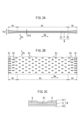
- FIG. 1 is a perspective view showing one embodiment of the laminate of the present invention.
- the upper nonwoven fabric sheet is drawn flat.
- the elastomer films and sheets are enlarged in the thickness direction and drawn thicker than they actually are, in order to facilitate understanding of the structure of the laminate.
- 2A is a cross-sectional view of the same laminate
- FIG. 2B is a partial plan view of the laminate
- FIG. 2C is an enlarged partial cross-sectional view of a joint and its surroundings.
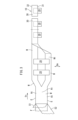
- FIG. 3 is a conceptual diagram showing an example of a method for manufacturing a worn article.
- FIG. 4A is a plan view showing an example of a worn article
- FIG. 4A is a plan view showing an example of a worn article
- FIG. 4B is an enlarged plan view showing a part of the waist portion
- FIG. 4C is a longitudinal sectional view of the same.
- the joints are colored in gray for easy viewing, and the elastomer film is given a dot pattern.
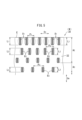
- FIG. 5 is an enlarged plan view showing a part of the waist portion.
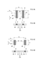
- 6A is an enlarged plan view showing the first joint portion
- FIG. 6B is a sectional view thereof
- FIG. 6C is an enlarged plan view showing a third joint portion
- FIG. 6D is a sectional view thereof.
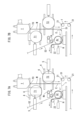
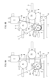
- 7A and 7B are layout diagrams showing an example of a process for forming film pass lines.
- 8A and 8B are layout diagrams showing an example of a process for forming pass lines for a film, respectively.
- 9A and 9B are schematic layout diagrams respectively showing an embodiment of the laminate manufacturing method and apparatus of the present invention.
- the length L of each joint 8 in the width direction Dw is longer than that of the joint 8 in the expansion and contraction direction Ds.
- the length of the joint in the expansion and contraction direction may be longer than the length in the width direction, but in this case, the effect of reducing the variation in the extension stress in the width direction is reduced.
- the length of the joint portion in the width direction longer than the length in the stretching direction, it is easy to obtain the effect of reducing the variation in the stretching stress in the width direction.
- the lengths L 1 and L 2 of the width direction Dw at the side edges AE are set longer than the length L 3 of the width direction Dw at the non-side edges Ac.
- the length in the width direction of the side edge portion becomes long, and it becomes easier to further reduce the variation in the above-described elongation stress in the width direction.
- the degree of necking is greater nearer the edges of the laminate, and the elastomeric film is often thicker nearer the edges.
- first joints 8 1 and second joints 8 2 intermittently arranged in the stretching direction Ds are provided in the side edges AE .
- the first joints 8-1 are provided at positions closest to the edge E of the side edges AE
- the row of the second joints 8-2 is provided next to the row of the first joints 8-1 . good too.
- the length L1 of the first joint portion 81 in the width direction Dw is longer than the length L2 of the second joint portion 82 in the width direction Dw.
- the first joint portion closest to the edge of the laminate has a longer width in the width direction than the second joint portion in the adjacent row, so that the closer to the edge, the thicker the elastomer film. Variation can be reduced.
- the non-side edge Ac is provided with a plurality of third joints 83 ,
- the length L2 of the second joint portion 82 in the width direction Dw is longer than the length L3 of the third joint portion 83 in the width direction Dw. In this case, it is possible to further reduce the variation in tensile stress between the side edges and the non-side edges.
- the arrangement pitch P1 of the joints 8 in the expansion/contraction direction Ds at the side edges AE is more than the arrangement pitch P3 of the joints 8 in the expansion/contraction direction Ds in the non-side edges Ac. , P2 are set small.
- the pitch of the joining portions By setting the pitch of the joining portions in this way, the sum of the lengths of the side edges can be set larger than the sum of the lengths of the non-side edges.
- the arrangement pitch P1 of the first joint portions 81 in the expansion / contraction direction Ds is smaller than the arrangement pitch P2 of the second joint portions 82 in the expansion/contraction direction Ds.
- the arrangement pitch of the first joints closest to the edge of the laminate is smaller than that of the second joints in the adjacent row, so that the closer to the edge the thicker the elastomer film, the greater the variation in tensile stress. obtain.
- the arrangement pitch P3 of the second joints 82 in the expansion/contraction direction Ds is greater than the arrangement pitch P3 in the expansion/contraction direction Ds of the third joints 83 in one row of the non-side edge portions Ac. 2 is small. In this case, it is possible to further reduce the variation in tensile stress between the side edges and the non-side edges.
- the first area ratio ⁇ 1 of the area of the joint portion 8 at the side edge portion AE to the unit area of the laminate at at least one side edge portion AE in the width direction Dw is It is larger than a second area ratio ⁇ 2 of the area of the joint portion 8 at the non-side edge portion Ac to the unit area of the laminate W at the non-side edge portion Ac in the width direction Dw.
- the joints in the present invention will be described.
- the elastomer film and the sheet are heat-sealed to each other, thereby maintaining the laminated state of the film and the sheet.
- the joint where both are heat-sealed to each other is in a loose state where the prestress generated during manufacturing is removed. Therefore, the joints reduce the susceptibility to shrinkage of the laminate.
- part of the resin component of the elastomer film enters between the fibers of the nonwoven fabric sheet, and the mechanically effective thickness of the film is reduced. Therefore, each joint has less resistance to elongation than its surroundings. Therefore, when the laminate is pulled in the stretching direction, it easily stretches.
- the joints can be said to be in a "saggy state" in the no-load state because of the characteristics of the joints that reduce the easiness of contraction of the laminate and facilitate the elongation thereof.
- the first area ratio ⁇ 1 of the joint at the side edge is greater than the second area ratio ⁇ 2 at the non-side edge. That is, the side edge has a larger area ratio of the joint than the non-side edge. Since the area ratio of the joint is large in this way, even if the side edge is thicker than the non-side edge due to necking, the "slack" joint reduces the drag of the side edge. , can be approximated to the non-side edge drag. Therefore, the variation in elongation stress in the width direction of the laminate is reduced.
- each joint portion 8 of a plurality of joint portions 8 in which the nonwoven fabric sheets S1 and S2 and the elastomer film F are heat-sealed to each other is formed by heat-sealing the sheets S1 and S2 and the elastomer film F to each other. including a fused region ⁇ ,
- the elastomer film F is broken at a boundary line 80 defining the fused region ⁇ .
- the opening 8H defined by the boundary line 80 expands greatly when the laminate is stretched in the stretching direction Ds. Therefore, the side edges having the joints 8 that are long in the width direction Dw tend to stretch even though the elastomer film F is thick.
- the thickness Th1 of the elastomer film F at the at least one side edge AE may be greater than the thickness Th3 of the elastomer film F at the non-side edge Ac.
- a part of the resin forming the elastomer film F enters between the plurality of fibers forming the nonwoven fabric sheets S1 and S2.
- the thickness of the elastomer film F at the joint portion 8 is thinner than the thickness of the elastomer film F at the non-joint portion 9 around the joint portion 8 .
- This thin film reduces the resistance to elongation at each joint, thus facilitating smaller variations in elongational stress in the elastomeric film.
- the laminate may constitute at least part of the waistline of the disposable wearing article, and the at least one side edge AE may be the upper edge or the lower edge of the waistline.
- This elastic laminate can be used for various purposes.
- a case where the present laminate is applied to a disposable diaper (an example of a wearable article) will be exemplified and explained below.
- a diaper includes a waist portion that covers the wearer's torso and a crotch portion that covers the wearer's crotch.
- the laminate is used for the waist portion.
- the laminate W shown in FIGS. 4A to 4C is formed by sandwiching a thermoplastic and stretchable elastomer film F between a pair of breathable nonwoven fabric sheets S1 and S2 containing thermoplastic fibers. be.
- the pair of nonwoven fabric sheets S1 and S2 and the film F are connected to each other at a number of joints 8 shown in FIG . They are heat-sealed and laminated.
- the laminate W can be used, for example, for flaps and girths of disposable diapers. In that case, the waist direction is the stretch direction Ds.
- Each joint 8 may be formed by vibration energy of an ultrasonic horn, or may be formed by heating with a heating roll.
- FIG. 4A shows a wearable article 10.
- the wearing article 10 has an absorbent main body 20 and a waist portion 30 .
- the absorbent main body 20 is long in the longitudinal direction orthogonal to the waistline direction.
- the worn article may be a pants type as shown in FIG. 4A, or may be a diaper type.
- the absorbent main body 20 is provided with an absorbent core (not shown). This absorbent core absorbs bodily fluids.
- the absorbent core is sandwiched between the topsheet and the backsheet. Each sheet and absorbent core are laminated together.
- the top sheet is made of a liquid-permeable thin nonwoven fabric and covers the skin surface of the absorbent core.
- a cuff (not shown) may be provided on the top sheet.
- the back sheet covers the non-skin surface of the absorbent core and is made of a liquid-impermeable resin sheet.
- a waist part 30 is attached to the longitudinal end of the absorbent main body 20 .
- the waist portion 30 is formed of a stretchable laminate W, extends in the wearer's waist direction, and is configured to cover the wearer's waist.
- the absorbent body 20 is configured to cover the crotch area of the wearer.
- FIG. 4B and 4C show structural examples of the laminated body W forming the waist portion 30.
- FIG. 4B and 4C show structural examples of the laminated body W forming the waist portion 30.
- first and second joints 8 1 , 8 2 are provided in a plurality of rows and a plurality of columns (two columns) on the upper edge 32 of the waist portion 30 .
- the vertically long third joints 83 are provided in a plurality of rows and a plurality of columns (in a matrix) on the lower portion 31 of the waist portion 30 .
- the joints 8 are intermittently arranged in the waistline direction and intermittently arranged in the longitudinal direction.
- a non-side edge portion Ac is formed in a region (intermediate portion) between a pair of side edge portions AE and AE .
- the laminate W shown in FIG. 1 includes a thermoplastic elastomer film F having greater elasticity in the stretching direction Ds than in the width direction Dw perpendicular to the stretching direction Ds, and first and second nonwoven fabric sheets S1 and S2. Laminated.
- the elastomer film F is sandwiched between a pair of sheets S1 and S2, but the number of nonwoven fabric sheets may be one.
- the thickness Th1 of the elastomer film F at the side edges AE on both sides is greater than the thickness Th3 of the elastomer film F at the non-side edges Ac.
- the joints 8 colored in gray are intermittently arranged in the width direction Dw and the stretch direction Ds. They are fused and laminated to each other.
- the thickness of the elastomer film F at the joint 8 is substantially thinner than the thickness of the elastomer film F at the non-joint portion 9 surrounding the joint 8 .
- the substantially thinned elastomeric film F reduces the elongation stress of the laminate W. As shown in FIG.
- each joint 8 in the width direction Dw corresponds to expansion and contraction of the joint 8. longer than that in direction Ds. That is, each joint 8 is, for example, a rectangle elongated in the width direction Dw. Each joint portion 8 having such a shape can easily reduce variations in stress in the width direction Dw generated in the laminate W. As shown in FIG.
- the sum ⁇ 1 of the first lengths and the sum ⁇ 2 of the second lengths are set as follows.
- Sum of first lengths ⁇ 1 The sum of the lengths of the joints 8 in the width direction Dw at at least one side edge AE in the width direction Dw per unit area of the laminate at the side edge AE .
- Sum of second lengths ⁇ 2 Sum of lengths of joint portions 8 in the width direction Dw at the non-side edges Ac in the width direction Dw per unit area of the laminate W at the non-side edges Ac.
- the first length sum ⁇ 1 defined above is greater than the second length sum ⁇ 2.
- the length L of each joint 8 and the pitch P of arrangement are set as follows. For the sake of convenience, subscripts are not attached when collectively referring to joints, lengths, and arrangement pitches.
- Each joint 8 may be rhombic, elliptical, hourglass-shaped, or the like. Also, the shape of each joint 8 may be a mixture of two or more shapes.
- the side edges A to E are provided with at least two rows of first joints 8-1 and second joints 8-2 intermittently arranged in the stretching direction Ds.
- the first joint portion 8-1 is provided at a position closest to the edge E in the side edge portions AE
- the row of the second joint portions 8-2 is provided next to the row of the first joint portions 8-1 .
- the non-side edge Ac is provided with a plurality of rows and a plurality of columns of third joints 83 .
- a fourth joint portion 84 having the same shape and size as the third joint portion 83 may be provided in a partial region of the side edge portions AE .
- the lengths and arrangement pitches of the first, second and third joints 8 are set as follows.
- the length of each joint 8 in the width direction Dw is set as follows.
- the lengths L 1 and L 2 in the width direction Dw at the side edges AE are longer than the length L 3 in the width direction Dw at the non-side edges Ac.
- the length L1 of the first joint portion 8-1 in the width direction Dw is greater than the length L2 of the second joint portion 82 in the width direction Dw.
- the lengths L 1 and L 2 of the first and second joint portions 8 1 and 8 2 in the width direction Dw are longer than the length L 3 of the third joint portion 8 3 in the width direction Dw.
- the length L2 of the second joint portion 8-2 may be longer than the length L1 of the first joint portion 8-1 .
- the arrangement pitch of the joint portions 8 in the width direction Dw is set as follows.
- the arrangement pitches P 1 and P 2 of the joints 8 in the stretch direction Ds at the side edges AE are smaller than the arrangement pitch P 3 of the joints 8 in the stretch direction Ds at the non-side edges Ac.
- the arrangement pitch P1 of the first joints 81 in the expansion/contraction direction Ds is smaller than the arrangement pitch P2 of the second joints 82 in the expansion/contraction direction Ds.
- the arrangement pitch P in the expansion and contraction direction Ds of the first and second joints 8 1 and 8 2 is greater than the arrangement pitch P 3 in the expansion and contraction direction Ds of the third joint 8 3 in one row of the non-side edge Ac.
- the arrangement pitch P2 of the second joints 8-2 may be smaller than the arrangement pitch P1 of the first joints 8-1 .
- it is desirable that the joints 8 are arranged in a zigzag manner so as not to be too close to each other.
- the lengths L 1 , L 2 and L 3 of the first, second and third joints need not be the same.
- the length L1 of the first joint portion may vary.
- each arrangement pitch P 1 , P 2 or P 3 may also vary.
- each of a plurality of joints 8 in which the nonwoven fabric sheets S1 and S2 and the elastomer film F are heat-sealed to each other is composed of the sheets S1 and S2 and the elastomer film F. are heat-sealed together.
- the elastomeric film F is in a broken state.
- the pair of non-woven fabric sheets S1 and S2 and the elastomer film F are heat-sealed to each other at the joints 8 colored in gray.
- the periphery of the joint 8 of the elastomer film F is broken during heat-sealing, or when it is re-stretched such as when worn.
- a hole 8H appears. Therefore, as can be seen by comparing FIGS. 6A and 6C, the longer the lengths L 1 to L 3 of the joints 8, the larger the openings 8H and the easier the laminate to stretch.
- first area ratio ⁇ 1 and the second area ratio ⁇ 2 are defined as follows.
- First area ratio ⁇ 1 Area ratio of the area of the joint portion 8 on at least one side edge AE in the width direction Dw to the unit area of the laminate at the side edge AE .
- Second area ratio ⁇ 2 Area ratio of the area of the joint portion 8 at the non-side edge Ac to the unit area of the laminate W at the non-side edge Ac.
- the first area ratio ⁇ 1 defined above is greater than the second area ratio ⁇ 2.
- Nip rolls sandwich the elastomer film F between two sheets (continuous nonwoven fabric) S1 and S2 having a pair of side edges AE extending in the conveying direction, and the first sheet S1 and the second sheet S2 and the elastomer film and F overlap each other to form a laminate W. As shown in FIG.
- the welding and joining may be heat sealing (heat welding) or welding by ultrasonic energy.
- the laminate W having the pair of side edges AE is slit along the transport direction by a slitter (not shown) while being transported in the transport direction.
- the laminate W becomes a pair of waistline continuities that form the front and rear waistlines 30 . That is, the laminate W having a non-side edge portion Ac between a pair of side edge portions AE as shown in FIG. be done.
- the two waistline continuities (laminates W) are relatively moved in the width direction Dw so as to separate from each other in the width direction Dw orthogonal to the conveying direction.
- the absorbent main body 20 straddles the pair of waistline continuities and partially overlaps each waistline continuum. Arranged (constructed) to form a continuous laminate W1.
- the continuous laminated body W1 is folded in two at the absorbent main body 20 so that the pair of waistline continuous bodies (laminated body W) overlap each other.
- Second seals are formed at end portions in the conveying direction of portions that become the front and rear waist portions 30, and the pair of waist continuous bodies are welded and joined to each other.
- This welding and joining may be welding by ultrasonic energy of an ultrasonic horn, or may be heat sealing.
- the continuous laminate W1 is cut into sizes (units) for individual wearing articles 10 along imaginary cutting lines indicated by two-dot chain lines. That is, in order to produce individual wearing articles 10 one after another, the continuous laminate W1 is cut one after another between the absorbent main bodies 20 adjacent to each other in the conveying direction. By this cutting, individual pants-type wearing articles 10 shown in FIG. 4A are obtained.
- the laminate thus forms at least a portion of the waistline portion 30 of the disposable wearing article, each of the side edges AE being an upper edge portion 32 of the waistline portion.
- FIG. 9B shows a steady state operation in which laminates W are continuously produced.
- the discharge section T is a well-known extruder called a T-die, and a molten thermoplastic elastomer (resin) is temporarily stored in the T-die.
- the T-die continuously produces the pre-elastomer M by ejecting a melted resin that becomes the pre-elastomer (an example of the film raw material) M from its ejection port TO.
- the pre-elastomer M discharged from the discharge port TO is caught on the outer peripheral surface of the first cooling roll T1 and is temporarily cooled, and is transported toward the outer peripheral surface of the second cooling roll T2 below the first cooling roll T1. be done.
- the pre-elastomer M is generally solidified and has elasticity (stretchability) as an elastomer film (an example of a thermoplastic film) F.
- the pre-elastomer M directed toward the second cooling roll T2 is secondary cooled by the outer peripheral surface of the second cooling roll T2. As a result, the pre-elastomer M is completely solidified into an elastomer film (elastic film) F.
- the secondarily cooled elastomer film F is sandwiched between the second cooling roll T2 and the nip roll Nr, and then directed to the joining roll Ar.
- the peripheral speed (conveyance speed) of the joining roll Ar is higher than that of the second cooling roll T2, so that the elastomer film F is stretched in the conveying direction between the nip roll Nr and the joining roll Ar.
- the molten resin becomes an elastomer film (thermoplastic film) F through the state of a pre-elastomer (film raw material) M.
- a pre-elastomer film raw material
- the molten resin as a substance transitions to the pre-elastomer M or transitions from the pre-elastomer M to the elastomer film F varies depending on the glass transition temperature, the thickness of the resin, and the room temperature. isn't it.
- the molten resin turns into a pre-elastomer M immediately after exiting the discharge port TO, and although it looks like a solid at first glance, it may have properties similar to a liquid without elasticity.
- the pre-elastomer M is changed to the elastomer film F at the portion where it is pulled downstream from the nip roll Nr, but when it becomes the elastomer film F after coming into contact with the second cooling roll T2 upstream of the nip roll Nr, There are various cases, such as the case where the elastomer film F is formed after coming into contact with one cooling roll T1.
- the film pass line 3 is a transport path for the film in which at least a portion of the film is in a pre-elastomer (film raw material) M state.
- first and second sheets S1 and S2 made of nonwoven fabric are supplied to the joining roll Ar.
- Each sheet S1, S2 is supplied to the joining roll Ar along a first pass line 1 or a second pass line 1A for sheets, respectively.
- the elastomer film F is introduced to the joining roll Ar while being sandwiched between the pair of sheets S1 and S2.
- a pair of sheets S1 and S2 and an elastomer film F are joined to each other by an ultrasonic horn H and stacked to form a laminate W.
- the laminated body W may be produced by heat welding with a heating roll instead of ultrasonic bonding with the ultrasonic horn H.
- the production of the laminate W is carried out continuously, but there are cases where the production is temporarily stopped due to size changes and the like. In this case, the formation of the film pass lines shown in FIGS. 7A to 9A is performed on the new elastomeric film F.
- FIG. 7A to 9A the formation of the film pass lines shown in FIGS. 7A to 9A is performed on the new elastomeric film F.
- Each cooling roll T1, T2 in FIG. 8B is rotatably supported by a slide base 6, and horizontally moved along a guider 4 by a cylinder 5 as shown in FIGS. 8B and 9A. be moved.
- Each cooling roll T1, T2 is rotationally driven at a peripheral speed Vs by a motor (not shown).
- the joining roll Ar is rotationally driven at a peripheral speed V higher than the peripheral speed Vs by a motor (not shown).
- each cooling roll T1, T2 is provided so as to be able to come into contact with and separate from the suspended pre-elastomer M in FIG. 7A.
- the ultrasonic horn H repeatedly vibrates the joining roll Ar with ultrasonic waves as shown in FIG.
- the laminate W is produced by bonding. That is, both the sheets S1 and S2 and the elastomer film F are conveyed while overlapping each other along the outer peripheral surface of the joining roll Ar, and the ultrasonic horn H vibrates the joining roll Ar with ultrasonic waves, thereby causing both the sheets S1 and S2 and the elastomer Ultrasonic energy is applied to the film F to bond and laminate the nonwoven fabric sheet and the elastomer film.
- This bonding is carried out by heat-sealing the elastomeric film F heated by ultrasonic energy to the non-woven fabric sheet.
- the film and sheet are joined while a tensile force acts on them due to the speed difference between the peripheral speed Vs of the second cooling roll T2 and the peripheral speed V of the joining roll Ar. Therefore, the elastomer film F softened by increasing the temperature is stretched in the stretching direction Ds of FIGS. 8H is formed on the elastomeric film F of the laminate W.
- the preferred embodiment has been described with reference to the drawings, but those skilled in the art will easily envision various changes and modifications within the obvious scope upon looking at this specification.
- the lower edge of the girth may have side edge structures.
- the upper and lower edges of the waist portion may have a side edge structure without slitting the laminate into two.
- the junction may be circular, square, or the like. Accordingly, such changes and modifications are intended to be within the scope of the invention as defined by the appended claims.
- the present invention can be used to manufacture laminates for wearing articles such as disposable diapers.
Abstract
This laminate is obtained by laminating a thermoplastic elastomer film, having greater stretchability in the stretching direction than in the width direction perpendicular to the stretching direction, and a nonwoven fabric sheet to each other, wherein: in each of joining sections which are intermittently arranged in the width direction and the stretching direction, the elastomer film and the nonwoven fabric sheet are laminated by thermal fusion; the sum of the width-direction lengths of the respective joining sections in at least one side edge section per unit area of the laminate in said side edge section in the width direction is greater than the sum of the width-direction lengths of the respective joining sections in a non-side edge section per unit area of the laminate in said non-side edge section in the width direction.
Description
本発明は使い捨てオムツやパンツなどの使い捨て着用物品の一部に利用できる伸縮性を有する積層体に関する。
The present invention relates to a stretchable laminate that can be used as part of disposable wearing articles such as disposable diapers and pants.
熱可塑性樹脂を主成分とする弾性樹脂材料をフィルム状に押し出し、冷却した後にフィルムの少なくとも一面側に基材シートを積層し、フィルムと基材シートとを間欠的に熱融着することで、伸縮性複合シートつまり伸縮性を有する積層体を生成することがなされている。
An elastic resin material containing a thermoplastic resin as a main component is extruded into a film, cooled, then laminated with a base sheet on at least one side of the film, and intermittently heat-sealed between the film and the base sheet. It has been attempted to produce stretchable composite sheets or stretchable laminates.
このような伸縮性複合シートを形成する際、フィルムを押し出した直後において溶融状態にある樹脂材料はネッキングにより押し出し方向に直交する幅方向に収縮し、冷却後は幅方向の両側縁部のフィルムの厚みが厚くなってしまい、その結果、伸縮性複合シートの伸長応力(力学的性質)が幅方向で異なることになる。
When forming such a stretchable composite sheet, the resin material in a molten state immediately after extruding the film shrinks in the width direction perpendicular to the extrusion direction due to necking, and after cooling, the film on both side edges in the width direction shrinks. As a result, the stretch stress (mechanical properties) of the stretchable composite sheet is different in the width direction.
伸長応力が均一な伸縮性複合シートを得るために、フィルムの厚みが厚い領域の複合シートの部位を全て切り取ることも考えられるが、こうすると材料の無駄が大きくなる。
In order to obtain a stretchable composite sheet with a uniform elongation stress, it is conceivable to cut off all the regions of the composite sheet where the film is thick, but this leads to a large waste of material.
本発明の目的は、材料の無駄を小さくでき、かつ、伸長応力のバラツキが小さい伸縮性複合シートつまり、伸縮性を有する積層体を得ることである。
The object of the present invention is to obtain a stretchable composite sheet that can reduce the waste of materials and has a small variation in elongation stress, that is, to obtain a stretchable laminate.
本発明の積層体は、伸縮方向Dsに直交する幅方向Dwよりも前記伸縮方向Dsに伸縮性が大きい熱可塑性のエラストマーフィルムFと、不織布のシートS1,S2とが互いに積層された積層体Wであって、
前記幅方向Dwおよび伸縮方向Dsに間欠的に配置された各接合部8において、前記エラストマーフィルムFと前記シートS1,S2とが互いに熱融着されて積層され、
前記幅方向Dwの少なくとも一方の側縁部AEにおける積層体の単位面積当りの当該側縁部AEにおける前記各接合部8の前記幅方向Dwの長さの和が、
前記幅方向Dwの非側縁部Acにおける積層体Wの単位面積当りの当該非側縁部Acにおける前記各接合部8の前記幅方向Dwの長さの和よりも大きい。 The laminate of the present invention is a laminate W in which a thermoplastic elastomer film F having greater elasticity in the stretching direction Ds than in the width direction Dw orthogonal to the stretching direction Ds and nonwoven fabric sheets S1 and S2 are laminated together. and
The elastomer film F and the sheets S1 and S2 are heat-sealed and laminated at each joint 8 intermittently arranged in the width direction Dw and the stretch direction Ds,
The sum of the lengths of the joint portions 8 in the width direction Dw at the side edge portions AE per unit area of the laminate at at least one side edge portion AE in the width direction Dw is
It is larger than the sum of the lengths in the width direction Dw of the joint portions 8 at the non-side edge Ac in the width direction Dw per unit area of the laminate W.
一対の不織布のシートとエラストマーフィルムFとは、接合部8において、互いに熱融着されている。エラストマーフィルムFの接合部8の周囲は熱融着時に破断したり、あるいは、着用時等の再伸長時に破断し、エラストマーフィルムFの伸長状態では開孔が現れる。この開孔はエラストマーフィルムが欠損しているため、小さな引張力で前記伸縮方向Dsに大きく伸びる。
The pair of nonwoven fabric sheets and the elastomer film F are heat-sealed to each other at the joint 8 . The periphery of the joint portion 8 of the elastomer film F is broken during heat-sealing, or is broken during re-stretching such as when worn, and holes appear when the elastomer film F is stretched. Since the elastomer film is missing in the opening, the opening is greatly elongated in the stretching direction Ds with a small tensile force.
この伸びの大きさは、開孔の前記幅方向Dwの長さが長い程大きくなる。この開孔の幅方向Dwの長さは接合部8の長さに近似した長さとなる。したがって、接合部8の幅方向Dwの長さの和が大きい程、小さな引張力で前記伸縮方向Dsに積層体が大きく伸びる。
The magnitude of this elongation increases as the length of the opening in the width direction Dw increases. The length of the opening in the width direction Dw is approximately the length of the joint 8 . Therefore, the larger the sum of the lengths of the joints 8 in the width direction Dw, the greater the expansion of the laminate in the stretching direction Ds with a smaller tensile force.
また、フィルムの厚みが厚い領域の積層体の部位を全て切り取る必要もないから、材料の無駄が著しく大きくなることもない。
In addition, since it is not necessary to cut off all the portions of the laminate in the region where the film is thick, the material is not wasted significantly.
なお、製品の見栄えを良くするためなどの観点から、積層体の側縁部の一部は切断除去されてもよい。
From the viewpoint of improving the appearance of the product, part of the side edges of the laminate may be cut off.
本発明において側縁部とは、積層体の縁に近く、かつ、接合部の幅方向Dwの長さの和が別の接合部の幅方向の長さの和よりも大きい領域を意味し、非側縁部とは側縁部以外の部分を意味する。
In the present invention, the side edge portion means a region near the edge of the laminate and in which the sum of the lengths in the width direction Dw of the joint portion is greater than the sum of the lengths in the width direction of another joint portion, Non-side edge means a portion other than the side edge.
好ましくは、前記各接合部8の前記幅方向Dwの長さLが当該接合部8の前記伸縮方向Dsのそれよりも長い。
Preferably, the length L of each joint 8 in the width direction Dw is longer than that of the joint 8 in the expansion and contraction direction Ds.
接合部の伸縮方向の長さを幅方向の長さよりも長くしてもよいが、この場合、伸長応力に関し、幅方向についてバラツキを小さくする効果が薄れる。これに対し、接合部の幅方向の長さを伸縮方向の長さよりも長くすることで、伸長応力に関し、幅方向についてバラツキを小さくする効果を得易い。
The length of the joint in the expansion and contraction direction may be longer than the length in the width direction, but in this case, the effect of reducing the variation in the extension stress in the width direction is reduced. On the other hand, by making the length of the joint portion in the width direction longer than the length in the stretching direction, it is easy to obtain the effect of reducing the variation in the stretching stress in the width direction.
好ましくは、前記非側縁部Acにおける前記幅方向Dwの長さL3よりも、前記側縁部AEにおける前記幅方向Dwの長さL1,L2を長く設定する。
Preferably, the lengths L 1 and L 2 of the width direction Dw at the side edges AE are set longer than the length L 3 of the width direction Dw at the non-side edges Ac.
この場合、側縁部における幅方向の長さが長くなり、前述の伸長応力に関し、幅方向についてのバラツキを更に小さくし易くなる。
In this case, the length in the width direction of the side edge portion becomes long, and it becomes easier to further reduce the variation in the above-described elongation stress in the width direction.
ネッキングの度合いは、積層体の縁に近い程大きく、エラストマーフィルムは、縁に近づくに従い厚くなっている場合が多い。
The degree of necking is greater nearer the edges of the laminate, and the elastomeric film is often thicker nearer the edges.
そのため、たとえば、前記側縁部AEにおいて前記伸縮方向Dsに間欠的に配置された少なくとも2列の第1接合部81および第2接合部82が設けられ、
前記第1接合部81は前記側縁部AEの最も縁Eに近い位置に設けられ、第2接合部82の列は前記第1接合部81の列の隣に設けられていてもよい。 Therefore, for example, at least two rows of first joints 8 1 and second joints 8 2 intermittently arranged in the stretching direction Ds are provided in the side edges AE ,
The first joints 8-1 are provided at positions closest to the edge E of the side edges AE , and the row of the second joints 8-2 is provided next to the row of the first joints 8-1 . good too.
この場合、好ましくは、前記第2接合部82の前記幅方向Dwの長さL2よりも、前記第1接合部81の前記幅方向Dwの長さL1が長い。
このように、積層体の最も縁に近い位置の第1接合部が隣の列の第2接合部に比べ幅方向の長さが長いことにより、縁に近い程、厚いエラストマーフィルムの伸長応力のバラツキを小さくし得る。 In this case, preferably, the length L1 of the first joint portion 81 in the width direction Dw is longer than the length L2 of the second joint portion 82 in the width direction Dw.
In this way, the first joint portion closest to the edge of the laminate has a longer width in the width direction than the second joint portion in the adjacent row, so that the closer to the edge, the thicker the elastomer film. Variation can be reduced.
更に好ましくは、前記非側縁部Acには第3接合部83が複数設けられ、
前記第3接合部83の前記幅方向Dwの長さL3よりも、前記第2接合部82の前記幅方向Dwの長さL2が長い。
この場合、側縁部と非側縁部とで伸長応力のバラツキを更に小さくすることができる。 More preferably, the non-side edge Ac is provided with a plurality of third joints 83 ,
The length L2 of the second joint portion 82 in the width direction Dw is longer than the length L3 of the third joint portion 83 in the width direction Dw.
In this case, it is possible to further reduce the variation in tensile stress between the side edges and the non-side edges.
好ましくは、前記非側縁部Acにおける前記伸縮方向Dsについての前記接合部8の配置ピッチP3よりも、前記側縁部AEにおける前記伸縮方向Dsについての前記接合部8の配置ピッチP1,P2を小さく設定する。
このように、接合部のピッチを設定すれば、側縁部の前記長さの和を非側縁部の前記長さの和よりも大きく設定し得る。 Preferably, the arrangement pitch P1 of the joints 8 in the expansion/contraction direction Ds at the side edges AE is more than the arrangement pitch P3 of the joints 8 in the expansion/contraction direction Ds in the non-side edges Ac. , P2 are set small.
By setting the pitch of the joining portions in this way, the sum of the lengths of the side edges can be set larger than the sum of the lengths of the non-side edges.
好ましくは、前記第2接合部82の前記伸縮方向Dsの配置ピッチP2よりも、前記第1接合部81の前記伸縮方向Dsの配置ピッチP1が小さい。
このように、積層体の最も縁に近い位置の第1接合部が隣の列の第2接合部に比べ配置ピッチが小さいことにより、縁に近い程厚いエラストマーフィルムの伸長応力のバラツキを小さくし得る。 Preferably, the arrangement pitch P1 of the first joint portions 81 in the expansion / contraction direction Ds is smaller than the arrangement pitch P2 of the second joint portions 82 in the expansion/contraction direction Ds.
In this way, the arrangement pitch of the first joints closest to the edge of the laminate is smaller than that of the second joints in the adjacent row, so that the closer to the edge the thicker the elastomer film, the greater the variation in tensile stress. obtain.
好ましくは、前記非側縁部Acの1つの列における前記第3接合部83の前記伸縮方向Dsの配置ピッチP3よりも、前記第2接合部82の前記伸縮方向Dsの配置ピッチP2が小さい。
この場合、側縁部と非側縁部とで伸長応力のバラツキを更に小さくすることができる。 Preferably, the arrangement pitch P3 of the second joints 82 in the expansion/contraction direction Ds is greater than the arrangement pitch P3 in the expansion/contraction direction Ds of the third joints 83 in one row of the non-side edge portions Ac. 2 is small.
In this case, it is possible to further reduce the variation in tensile stress between the side edges and the non-side edges.
好ましくは、前記幅方向Dwの少なくとも一方の側縁部AEにおける積層体の単位面積に対する当該側縁部AEにおける前記接合部8の面積の第1面積比α1が、
前記幅方向Dwの非側縁部Acにおける積層体Wの単位面積に対する当該非側縁部Acにおける前記接合部8の面積の第2面積比α2よりも大きい。 Preferably, the first area ratio α1 of the area of the joint portion 8 at the side edge portion AE to the unit area of the laminate at at least one side edge portion AE in the width direction Dw is
It is larger than a second area ratio α2 of the area of the joint portion 8 at the non-side edge portion Ac to the unit area of the laminate W at the non-side edge portion Ac in the width direction Dw.
ここで、本発明における接合部について説明する。
各接合部においては、エラストマーフィルムとシートが互いに熱融着されており、これにより上記フィルムとシートとが積層された状態が維持される。両者が互いに熱融着された接合部は、製造時に生じたプレストレスが除去された緩んだ状態となっている。したがって、接合部は積層体の縮み易さを緩和する。
また、接合部においては、エラストマーフィルムの樹脂成分の一部が不織布のシートの繊維間に入り込んでおり、前記フィルムの力学的に有効な厚さが小さくなっている。そのため、各接合部はその周囲の部分に比べ、伸びに対する抗力が小さくなっている。したがって、積層体を伸縮方向に引っ張ったときに伸び易い。 Here, the joints in the present invention will be described.
At each junction, the elastomer film and the sheet are heat-sealed to each other, thereby maintaining the laminated state of the film and the sheet. The joint where both are heat-sealed to each other is in a loose state where the prestress generated during manufacturing is removed. Therefore, the joints reduce the susceptibility to shrinkage of the laminate.
Moreover, at the joint portion, part of the resin component of the elastomer film enters between the fibers of the nonwoven fabric sheet, and the mechanically effective thickness of the film is reduced. Therefore, each joint has less resistance to elongation than its surroundings. Therefore, when the laminate is pulled in the stretching direction, it easily stretches.
以上のように接合部は積層体の縮み易さを緩和し、かつ、伸び易くする特性から、無負荷状態において、接合部は“たるんだ状態”であるといえる。
As described above, the joints can be said to be in a "saggy state" in the no-load state because of the characteristics of the joints that reduce the easiness of contraction of the laminate and facilitate the elongation thereof.
ここで、側縁部における接合部の第1面積比α1は、非側縁部における第2面積比α2よりも大きい。つまり、側縁部は非側縁部に比べ接合部の面積比が大きい。このように接合部の面積比が大きいため、側縁部は非側縁部に比べ、ネッキングにより肉厚となっていても、“たるんだ状態”の接合部が側縁部の抗力を低下させ、非側縁部の抗力に近づけることができる。したがって、積層体の幅方向について伸長応力のバラツキが小さくなる。
Here, the first area ratio α1 of the joint at the side edge is greater than the second area ratio α2 at the non-side edge. That is, the side edge has a larger area ratio of the joint than the non-side edge. Since the area ratio of the joint is large in this way, even if the side edge is thicker than the non-side edge due to necking, the "slack" joint reduces the drag of the side edge. , can be approximated to the non-side edge drag. Therefore, the variation in elongation stress in the width direction of the laminate is reduced.
好ましくは、前記不織布のシートS1,S2と前記エラストマーフィルムFとが互いに熱融着された複数の接合部8の各接合部8は前記シートS1,S2および前記エラストマーフィルムFが互いに熱融着された融着領域αを含み、
前記融着領域αを定義する境界ライン80において、前記エラストマーフィルムFが破断した状態である。
この場合、前述のように、積層体が伸縮方向Dsに伸びる際に境界ライン80で定義される開孔8Hが大きく拡がる。そのため、幅方向Dwに長い接合部8を有する側縁部はエラストマーフィルムFが肉厚であるにもかかわらず伸び易い。 Preferably, each joint portion 8 of a plurality of joint portions 8 in which the nonwoven fabric sheets S1 and S2 and the elastomer film F are heat-sealed to each other is formed by heat-sealing the sheets S1 and S2 and the elastomer film F to each other. including a fused region α,
The elastomer film F is broken at aboundary line 80 defining the fused region α.
In this case, as described above, theopening 8H defined by the boundary line 80 expands greatly when the laminate is stretched in the stretching direction Ds. Therefore, the side edges having the joints 8 that are long in the width direction Dw tend to stretch even though the elastomer film F is thick.
前記融着領域αを定義する境界ライン80において、前記エラストマーフィルムFが破断した状態である。
この場合、前述のように、積層体が伸縮方向Dsに伸びる際に境界ライン80で定義される開孔8Hが大きく拡がる。そのため、幅方向Dwに長い接合部8を有する側縁部はエラストマーフィルムFが肉厚であるにもかかわらず伸び易い。 Preferably, each joint portion 8 of a plurality of joint portions 8 in which the nonwoven fabric sheets S1 and S2 and the elastomer film F are heat-sealed to each other is formed by heat-sealing the sheets S1 and S2 and the elastomer film F to each other. including a fused region α,
The elastomer film F is broken at a
In this case, as described above, the
積層体において、前記少なくとも一方の側縁部AEにおける前記エラストマーフィルムFの厚さTh1が、前記非側縁部Acにおける前記エラストマーフィルムFの厚さTh3よりも大きくてもよい。
In the laminate, the thickness Th1 of the elastomer film F at the at least one side edge AE may be greater than the thickness Th3 of the elastomer film F at the non-side edge Ac.
好ましくは、前記各接合部8において、前記エラストマーフィルムFを構成する樹脂の一部が、前記不織布のシートS1,S2を構成する複数の繊維の間に入り込んでいる。
Preferably, at each joint 8, a part of the resin forming the elastomer film F enters between the plurality of fibers forming the nonwoven fabric sheets S1 and S2.
この場合、前記接合部8における前記エラストマーフィルムFの厚さが、当該接合部8の周囲の非接合部9における前記エラストマーフィルムFの厚さよりも薄い。
In this case, the thickness of the elastomer film F at the joint portion 8 is thinner than the thickness of the elastomer film F at the non-joint portion 9 around the joint portion 8 .
このようにフィルムが薄いため、各接合部における伸びに対する抗力が小さくなり、したがって、エラストマーフィルムの伸長応力のバラツキを小さくすることが容易になる。
This thin film reduces the resistance to elongation at each joint, thus facilitating smaller variations in elongational stress in the elastomeric film.
たとえば、前記積層体は使い捨て着用物品の胴回り部の少なくとも一部を構成し、前記少なくとも一方の側縁部AEは前記胴回り部における上縁部または下縁部であってもよい。
For example, the laminate may constitute at least part of the waistline of the disposable wearing article, and the at least one side edge AE may be the upper edge or the lower edge of the waistline.
この場合、胴回り部の上縁部や下縁部において伸長応力が大きくなるとういう事態を回避することができ、着用感が向上する。
In this case, it is possible to avoid a situation in which the extension stress is increased at the upper edge and the lower edge of the waist portion, and the wearing comfort is improved.
1つの前記各実施態様または下記の実施例に関連して説明および/または図示した特徴は、1つまたはそれ以上の他の実施態様または他の実施例において同一または類似な形で、および/または他の実施態様または実施例の特徴と組み合わせて、または、その代わりに利用することができる。
Features described and/or illustrated in connection with one of the foregoing embodiments or examples below may be the same or analogous in one or more other embodiments or examples, and/or Features of other embodiments or examples may be used in combination with or in place of them.
本発明は、添付の図面を参考にした以下の好適な実施例の説明からより明瞭に理解されるであろう。しかし、実施例および図面は単なる図示および説明のためのものであり、本発明の範囲を定めるために利用されるべきものではない。本発明の範囲は請求の範囲によってのみ定まる。添付図面において、複数の図面における同一の部品番号は、同一または相当部分を示す。
なお、本明細書のカタカナ表記の一部には、その意味をより明瞭にするために英単語を()書で併記している。 The present invention will be more clearly understood from the following description of preferred embodiments with reference to the accompanying drawings. However, the examples and drawings are for illustration and description only and should not be used to define the scope of the invention. The scope of the invention is defined only by the claims. In the accompanying drawings, the same part number in multiple drawings indicates the same or corresponding part.
In addition, in some of the katakana notations in this specification, English words are also written in parentheses in order to make the meaning clearer.
以下、本発明の一実施例を図面にしたがって説明する。
An embodiment of the present invention will be described below with reference to the drawings.
本伸縮性積層体は、種々の用途に用いることができる。以下、本積層体を使い捨てオムツ(着用物品の一例)に適用した場合について例示して説明する。オムツは、着用者の胴を覆う胴回り部と、着用者の股間を覆う股部とを備えている。積層体は、胴回り部に用いられる。
This elastic laminate can be used for various purposes. A case where the present laminate is applied to a disposable diaper (an example of a wearable article) will be exemplified and explained below. A diaper includes a waist portion that covers the wearer's torso and a crotch portion that covers the wearer's crotch. The laminate is used for the waist portion.
伸縮積層体を使い捨てオムツに用いた場合の詳しい構造は例えば、US2013/0110073A1(WO2012/017817A1)に開示されており、これらの開示の全てがここに組み込まれる。
A detailed structure in the case of using a stretchable laminate for a disposable diaper is disclosed, for example, in US2013/0110073A1 (WO2012/017817A1), and all of these disclosures are incorporated herein.
図4A~図4Cに示す積層体Wは熱可塑性繊維を含む通気性を有する一対の不織布のシートS1,S2の間に熱可塑性で、かつ、伸縮性を有するエラストマーフィルムFが挟まれて形成される。
The laminate W shown in FIGS. 4A to 4C is formed by sandwiching a thermoplastic and stretchable elastomer film F between a pair of breathable nonwoven fabric sheets S1 and S2 containing thermoplastic fibers. be.
一対の不織布のシートS1,S2とフィルムFとは、図4Bに示す多数の接合部8(以下、接合部81,82,83を総称する場合などにおいては接合部8という)において互いに熱融着されて積層されている。積層体Wは例えば使い捨てオムツのフラップや胴回り部に用いることができる。その場合、胴回り方向が伸縮方向Dsとなる。
The pair of nonwoven fabric sheets S1 and S2 and the film F are connected to each other at a number of joints 8 shown in FIG . They are heat-sealed and laminated. The laminate W can be used, for example, for flaps and girths of disposable diapers. In that case, the waist direction is the stretch direction Ds.
各接合部8は超音波ホーンの振動エネルギーにより形成されてもよいし、加熱ロールにより昇温されて形成されてもよい。
Each joint 8 may be formed by vibration energy of an ultrasonic horn, or may be formed by heating with a heating roll.
本積層体の詳細な説明に先立って着用物品の一例について説明する。
図4Aは着用物品10を示す。
この図に示すように、着用物品10は、吸収性本体20および胴回り部30を備えている。吸収性本体20は、胴回り方向に直交する縦方向に長い。着用物品は図4Aのパンツ型であってもよいし、オムツ型であってもよい。 An example of the wearing article will be described prior to detailed description of the laminate.
FIG. 4A shows awearable article 10. FIG.
As shown in this figure, the wearingarticle 10 has an absorbent main body 20 and a waist portion 30 . The absorbent main body 20 is long in the longitudinal direction orthogonal to the waistline direction. The worn article may be a pants type as shown in FIG. 4A, or may be a diaper type.
図4Aは着用物品10を示す。
この図に示すように、着用物品10は、吸収性本体20および胴回り部30を備えている。吸収性本体20は、胴回り方向に直交する縦方向に長い。着用物品は図4Aのパンツ型であってもよいし、オムツ型であってもよい。 An example of the wearing article will be described prior to detailed description of the laminate.
FIG. 4A shows a
As shown in this figure, the wearing
吸収性本体20には図示しない吸収コアが設けられている。この吸収コアは体液を吸収する。吸収コアは、トップシートとバックシートとの間で挟まれている。各シートおよび吸収コアは互いに積層されている。
The absorbent main body 20 is provided with an absorbent core (not shown). This absorbent core absorbs bodily fluids. The absorbent core is sandwiched between the topsheet and the backsheet. Each sheet and absorbent core are laminated together.
トップシートは透液性の薄い不織布からなり、吸収コアの肌面を覆う。このトップシートの上には図示しないカフが設けられていてもよい。
The top sheet is made of a liquid-permeable thin nonwoven fabric and covers the skin surface of the absorbent core. A cuff (not shown) may be provided on the top sheet.
バックシートは吸収コアの非肌面を覆い、液不透過性の樹脂シートからなる。吸収性本体20の縦方向の端部には、胴回り部30が貼り付けられている。
The back sheet covers the non-skin surface of the absorbent core and is made of a liquid-impermeable resin sheet. A waist part 30 is attached to the longitudinal end of the absorbent main body 20 .
胴回り部30は伸縮性の積層体Wにより形成され着用者の胴回り方向に延び着用者の胴を覆うように構成されている。吸収性本体20は着用者の股間を覆うように構成されている。
The waist portion 30 is formed of a stretchable laminate W, extends in the wearer's waist direction, and is configured to cover the wearer's waist. The absorbent body 20 is configured to cover the crotch area of the wearer.
図4Bおよび図4Cは胴回り部30を構成する積層体Wの構造例を示す。
4B and 4C show structural examples of the laminated body W forming the waist portion 30. FIG.
縦長の第1および第2接合部81,82は胴回り部30の上縁部32に複数行および複数列(2列)設けられている。縦長の第3接合部83は胴回り部30の下部31に複数行および複数列(マトリクス状に)設けられている。各接合部8は胴回り方向に間欠的に配置され、かつ、縦方向に間欠的に配置されている。
Longitudinal first and second joints 8 1 , 8 2 are provided in a plurality of rows and a plurality of columns (two columns) on the upper edge 32 of the waist portion 30 . The vertically long third joints 83 are provided in a plurality of rows and a plurality of columns (in a matrix) on the lower portion 31 of the waist portion 30 . The joints 8 are intermittently arranged in the waistline direction and intermittently arranged in the longitudinal direction.
つぎに、積層体Wの構造の詳細を説明する。
図1に示す積層体Wにおいては、一対の側縁部AE,AEの間の領域(中間部)に非側縁部Acが形成されている。 Next, the details of the structure of the laminate W will be described.
In the laminate W shown in FIG. 1, a non-side edge portion Ac is formed in a region (intermediate portion) between a pair of side edge portions AE and AE .
図1に示す積層体Wにおいては、一対の側縁部AE,AEの間の領域(中間部)に非側縁部Acが形成されている。 Next, the details of the structure of the laminate W will be described.
In the laminate W shown in FIG. 1, a non-side edge portion Ac is formed in a region (intermediate portion) between a pair of side edge portions AE and AE .
図1に示す積層体Wは、伸縮方向Dsに直交する幅方向Dwよりも伸縮方向Dsに伸縮性が大きい熱可塑性のエラストマーフィルムFと、不織布の第1および第2シートS1,S2とが互いに積層されている。本例の場合、エラストマーフィルムFは一対のシートS1,S2にサンドイッチされているが不織布のシートは1枚であってもよい。
The laminate W shown in FIG. 1 includes a thermoplastic elastomer film F having greater elasticity in the stretching direction Ds than in the width direction Dw perpendicular to the stretching direction Ds, and first and second nonwoven fabric sheets S1 and S2. Laminated. In the case of this example, the elastomer film F is sandwiched between a pair of sheets S1 and S2, but the number of nonwoven fabric sheets may be one.
両側の側縁部AEにおけるエラストマーフィルムFの厚さTh1は、非側縁部AcにおけるエラストマーフィルムFの厚さTh3よりも大きい。
The thickness Th1 of the elastomer film F at the side edges AE on both sides is greater than the thickness Th3 of the elastomer film F at the non-side edges Ac.
図1において、グレーで着色して示す各接合部8は、幅方向Dwおよび伸縮方向Dsに間欠的に配置され、これらの各接合部8において、エラストマーフィルムFとシートS1,S2とが互いに熱融着されて互いに積層されている。
In FIG. 1, the joints 8 colored in gray are intermittently arranged in the width direction Dw and the stretch direction Ds. They are fused and laminated to each other.
図2Cに網点で示すように、各接合部8において、エラストマーフィルムFを構成する樹脂成分の一部は、不織布のシートS1,S2を構成する複数の繊維の間に入り込んでいる。したがって、接合部8におけるエラストマーフィルムFの厚さは、当該接合部8の周囲の非接合部9におけるエラストマーフィルムFの厚さよりも実質的に薄い。
As indicated by halftone dots in FIG. 2C, at each joint 8, part of the resin component forming the elastomeric film F enters between the plurality of fibers forming the nonwoven fabric sheets S1 and S2. Therefore, the thickness of the elastomer film F at the joint 8 is substantially thinner than the thickness of the elastomer film F at the non-joint portion 9 surrounding the joint 8 .
このように実質的に薄くなったエラストマーフィルムFは、積層体Wの伸長応力を小さくする。
The substantially thinned elastomeric film F reduces the elongation stress of the laminate W. As shown in FIG.
図1に示すように、各接合部8の幅方向Dwの長さL(以下、長さL1,L2,L3を総称する場合等は長さLという)は当該接合部8の伸縮方向Dsのそれよりも長い。すなわち、各接合部8は幅方向Dwに長い例えば長方形である。こうした形状の各接合部8は、積層体Wに生じる幅方向Dwの応力のバラツキを小さくし易い。
As shown in FIG. 1, the length L of each joint 8 in the width direction Dw (hereinafter referred to as length L when collectively referring to lengths L 1 , L 2 , and L 3 ) corresponds to expansion and contraction of the joint 8. longer than that in direction Ds. That is, each joint 8 is, for example, a rectangle elongated in the width direction Dw. Each joint portion 8 having such a shape can easily reduce variations in stress in the width direction Dw generated in the laminate W. As shown in FIG.
ここで、第1長さの和Σ1および第2長さの和Σ2について下記のように設定する。
第1長さの和Σ1:幅方向Dwの少なくとも一方の側縁部AEにおける積層体の単位面積当りの当該側縁部AEにおける各接合部8の幅方向Dwの長さの和。
第2長さの和Σ2:幅方向Dwの非側縁部Acにおける積層体Wの単位面積当りの当該非側縁部Acにおける各接合部8の幅方向Dwの長さの和。 Here, the sum Σ1 of the first lengths and the sum Σ2 of the second lengths are set as follows.
Sum of first lengths Σ1: The sum of the lengths of the joints 8 in the width direction Dw at at least one side edge AE in the width direction Dw per unit area of the laminate at the side edge AE .
Sum of second lengths Σ2: Sum of lengths of joint portions 8 in the width direction Dw at the non-side edges Ac in the width direction Dw per unit area of the laminate W at the non-side edges Ac.
上記のように定義された第1長さの和Σ1は、第2長さの和Σ2よりも大きい。このような長さの和の関係に設定するために、本例では各接合部8の長さLや配置のピッチPについて以下のように設定されている。
接合部、長さおよび配置ピッチの各々について総称する場合等は、便宜上、下付数字を添えない。 The first length sum Σ1 defined above is greater than the second length sum Σ2. In order to set such a relationship of the sum of lengths, in this example, the length L of each joint 8 and the pitch P of arrangement are set as follows.
For the sake of convenience, subscripts are not attached when collectively referring to joints, lengths, and arrangement pitches.
なお、各接合部8は、ひし形,だ円形状・砂時計型などであってもよい。また、各接合部8の形状は2種類以上の形状が混合されていてもよい。
Each joint 8 may be rhombic, elliptical, hourglass-shaped, or the like. Also, the shape of each joint 8 may be a mixture of two or more shapes.
図1において、前記側縁部AEには前記伸縮方向Dsに間欠的に配置された少なくとも2列の第1接合部81および第2接合部82が設けられている。この第1接合部81は側縁部AEにおける最も縁Eに近い位置に設けられ、第2接合部82の列は第1接合部81の列の隣に設けられている。
一方、非側縁部Acには第3接合部83が複数行かつ複数列設けられている。なお、本例のように、側縁部AEの一部の領域には第3接合部83と同じ形状、大きさの第4接合部84が設けられていてもよい In FIG. 1, the side edges A to E are provided with at least two rows of first joints 8-1 and second joints 8-2 intermittently arranged in the stretching direction Ds. The first joint portion 8-1 is provided at a position closest to the edge E in the side edge portions AE , and the row of the second joint portions 8-2 is provided next to the row of the first joint portions 8-1 .
On the other hand, the non-side edge Ac is provided with a plurality of rows and a plurality of columns of third joints 83 . Note that, as in this example, a fourthjoint portion 84 having the same shape and size as the third joint portion 83 may be provided in a partial region of the side edge portions AE .
一方、非側縁部Acには第3接合部83が複数行かつ複数列設けられている。なお、本例のように、側縁部AEの一部の領域には第3接合部83と同じ形状、大きさの第4接合部84が設けられていてもよい In FIG. 1, the side edges A to E are provided with at least two rows of first joints 8-1 and second joints 8-2 intermittently arranged in the stretching direction Ds. The first joint portion 8-1 is provided at a position closest to the edge E in the side edge portions AE , and the row of the second joint portions 8-2 is provided next to the row of the first joint portions 8-1 .
On the other hand, the non-side edge Ac is provided with a plurality of rows and a plurality of columns of third joints 83 . Note that, as in this example, a fourth
前述のような長さの和の関係を得るために、本例では、以下のように第1、第2および第3接合部8の長さや配置ピッチを設定した。
In order to obtain the relationship of the sum of the lengths as described above, in this example, the lengths and arrangement pitches of the first, second and third joints 8 are set as follows.
例えば、各接合部8の幅方向Dwの長さは以下のように設定されている。
図1において、非側縁部Acにおける前記幅方向Dwの長さL3よりも、側縁部AEにおける前記幅方向Dwの長さL1,L2が大きい。更に詳しくは、第2接合部82の前記幅方向Dwの長さL2よりも、第1接合部81の前記幅方向Dwの長さL1が大きい。また、第3接合部83の前記幅方向Dwの長さL3よりも、第1および第2接合部81,82の前記幅方向Dwの長さL1,L2が大きい。なお、第2接合部82の長さL2が第1接合部81の長さL1よりも大きくてもよい。 For example, the length of each joint 8 in the width direction Dw is set as follows.
In FIG. 1, thelengths L 1 and L 2 in the width direction Dw at the side edges AE are longer than the length L 3 in the width direction Dw at the non-side edges Ac. More specifically, the length L1 of the first joint portion 8-1 in the width direction Dw is greater than the length L2 of the second joint portion 82 in the width direction Dw. Moreover, the lengths L 1 and L 2 of the first and second joint portions 8 1 and 8 2 in the width direction Dw are longer than the length L 3 of the third joint portion 8 3 in the width direction Dw. The length L2 of the second joint portion 8-2 may be longer than the length L1 of the first joint portion 8-1 .
図1において、非側縁部Acにおける前記幅方向Dwの長さL3よりも、側縁部AEにおける前記幅方向Dwの長さL1,L2が大きい。更に詳しくは、第2接合部82の前記幅方向Dwの長さL2よりも、第1接合部81の前記幅方向Dwの長さL1が大きい。また、第3接合部83の前記幅方向Dwの長さL3よりも、第1および第2接合部81,82の前記幅方向Dwの長さL1,L2が大きい。なお、第2接合部82の長さL2が第1接合部81の長さL1よりも大きくてもよい。 For example, the length of each joint 8 in the width direction Dw is set as follows.
In FIG. 1, the
一方、各接合部8の幅方向Dwの配置ピッチは以下のように設定されている。
図1において、非側縁部Acにおける伸縮方向Dsについての接合部8の配置ピッチP3よりも、側縁部AEにおける伸縮方向Dsについての接合部8の配置ピッチP1,P2が小さい。更に詳しくは、第2接合部82の伸縮方向Dsの配置ピッチP2よりも、第1接合部81の伸縮方向Dsの配置ピッチP1が小さい。また、非側縁部Acの1つの列における第3接合部83の伸縮方向Dsの配置ピッチP3よりも、第1および第2接合部81,82の伸縮方向Dsの配置ピッチP1,P2が小さい。なお、第2接合部82の配置ピッチP2が第1接合部81の配置ピッチP1よりも小さくてもよい。
なお、各接合部8は互いに接近しすぎないように千鳥状に配列するのが望ましい。 On the other hand, the arrangement pitch of the joint portions 8 in the width direction Dw is set as follows.
In FIG. 1, the arrangement pitches P 1 and P 2 of the joints 8 in the stretch direction Ds at the side edges AE are smaller than the arrangement pitch P 3 of the joints 8 in the stretch direction Ds at the non-side edges Ac. . More specifically, the arrangement pitch P1 of the first joints 81 in the expansion/contraction direction Ds is smaller than the arrangement pitch P2 of the second joints 82 in the expansion/contraction direction Ds. In addition, the arrangement pitch P in the expansion and contraction direction Ds of the first and second joints 8 1 and 8 2 is greater than the arrangement pitch P 3 in the expansion and contraction direction Ds of the third joint 8 3 in one row of the non-side edge Ac. 1 and P2 are small. The arrangement pitch P2 of the second joints 8-2 may be smaller than the arrangement pitch P1 of the first joints 8-1 .
In addition, it is desirable that the joints 8 are arranged in a zigzag manner so as not to be too close to each other.
なお、各第1、第2および第3接合部の長さL1,L2,L3は、それぞれ、同一である必要はない。例えば第1接合部の長さL1にバラツキがあってもよい。
また、各配置ピッチP1,P2またはP3についても同様にバラツキがあってもよい。 It should be noted that the lengths L 1 , L 2 and L 3 of the first, second and third joints need not be the same. For example, the length L1 of the first joint portion may vary.
Further, each arrangement pitch P 1 , P 2 or P 3 may also vary.
また、各配置ピッチP1,P2またはP3についても同様にバラツキがあってもよい。 It should be noted that the lengths L 1 , L 2 and L 3 of the first, second and third joints need not be the same. For example, the length L1 of the first joint portion may vary.
Further, each arrangement pitch P 1 , P 2 or P 3 may also vary.
図5,図6A~図6Dに示すように、不織布のシートS1,S2とエラストマーフィルムFとが互いに熱融着された複数の接合部8の各接合部8はシートS1,S2およびエラストマーフィルムFが互いに熱融着された融着領域αを含む。この融着領域αを定義する境界ライン80において、エラストマーフィルムFは破断した状態である。
As shown in FIGS. 5 and 6A to 6D, each of a plurality of joints 8 in which the nonwoven fabric sheets S1 and S2 and the elastomer film F are heat-sealed to each other is composed of the sheets S1 and S2 and the elastomer film F. are heat-sealed together. At the boundary line 80 defining this fused region α, the elastomeric film F is in a broken state.
一対の不織布のシートS1,S2とエラストマーフィルムFとは、グレーで着色した接合部8において、互いに熱融着されている。エラストマーフィルムFの接合部8の周囲は熱融着時に破断したり、あるいは、着用時等の再伸長時に破断し、図5,図6Bおよび図6DのエラストマーフィルムFの伸長状態では破線で示す開孔8Hが現れる。したがって、図6Aおよび図6Cを比較すると分かるように、接合部8の長さL1~L3が長い程、開孔8Hが大きく、積層体が伸び易い。
The pair of non-woven fabric sheets S1 and S2 and the elastomer film F are heat-sealed to each other at the joints 8 colored in gray. The periphery of the joint 8 of the elastomer film F is broken during heat-sealing, or when it is re-stretched such as when worn. A hole 8H appears. Therefore, as can be seen by comparing FIGS. 6A and 6C, the longer the lengths L 1 to L 3 of the joints 8, the larger the openings 8H and the easier the laminate to stretch.
ここで、第1面積比α1および第2面積比α2について下記のように定義する。
第1面積比α1:幅方向Dwの少なくとも一方の側縁部AEにおける積層体の単位面積に対する当該側縁部AEにおける接合部8の面積の面積比。
第2面積比α2:非側縁部Acにおける積層体Wの単位面積に対する当該非側縁部Acにおける接合部8の面積の面積比。
上記のように定義された第1面積比α1は第2面積比α2よりも大きい。 Here, the first area ratio α1 and the second area ratio α2 are defined as follows.
First area ratio α1: Area ratio of the area of the joint portion 8 on at least one side edge AE in the width direction Dw to the unit area of the laminate at the side edge AE .
Second area ratio α2: Area ratio of the area of the joint portion 8 at the non-side edge Ac to the unit area of the laminate W at the non-side edge Ac.
The first area ratio α1 defined above is greater than the second area ratio α2.
つぎに、積層体Wから胴回り部を得て、着用物品を生成する方法の一例について簡単に説明する。
図3に示すように、搬送方向に延びるエラストマーフィルムFが搬送方向に伸張された状態で搬送方向に搬送される。 Next, an example of a method of producing a worn article by obtaining a waistline portion from the laminate W will be briefly described.
As shown in FIG. 3, the elastomer film F extending in the transport direction is stretched in the transport direction and transported in the transport direction.
図示しないニップロールは搬送方向に延びる一対の側縁部AEを有する2枚のシート(連続不織布)S1,S2の間にエラストマーフィルムFを挟むと共に、第1シートS1,第2シートS2とエラストマーフィルムFとが互いに重なるように接合して積層体Wを生成する。
Nip rolls (not shown) sandwich the elastomer film F between two sheets (continuous nonwoven fabric) S1 and S2 having a pair of side edges AE extending in the conveying direction, and the first sheet S1 and the second sheet S2 and the elastomer film and F overlap each other to form a laminate W. As shown in FIG.
すなわち、図1の前記伸縮方向Dsに間欠的に、かつ、前記幅方向Dwに間欠的に前記シートS1,S2とエラストマーフィルムFが多数の第1~第3接合部81,82,83で互いに溶着接合される。ここで、溶着接合はヒートシール(熱溶着)であってもよいし、超音波エネルギーによる溶着であってもよい。
1 intermittently in the stretching direction Ds and intermittently in the width direction Dw . are welded together. Here, the welding and joining may be heat sealing (heat welding) or welding by ultrasonic energy.
図3に示すように、前記一対の側縁部AEを有する積層体Wは搬送方向に搬送されながら搬送方向に沿ってスリッタ(図示せず)でスリットされる。これにより、積層体Wは前後の胴回り部30となる一対の胴回り連続体となる。すなわち、図1のように一対の側縁部AEの間に非側縁部Acを有する積層体Wは、図4Bの一方の側縁部が上縁部32となった胴回り部30に加工される。図3の前記スリット後、搬送方向に直交する幅方向Dwに互いに離間するように、2つの胴回り連続体(積層体W)が幅方向Dwに相対移動される。
As shown in FIG. 3, the laminate W having the pair of side edges AE is slit along the transport direction by a slitter (not shown) while being transported in the transport direction. As a result, the laminate W becomes a pair of waistline continuities that form the front and rear waistlines 30 . That is, the laminate W having a non-side edge portion Ac between a pair of side edge portions AE as shown in FIG. be done. After the slitting in FIG. 3, the two waistline continuities (laminates W) are relatively moved in the width direction Dw so as to separate from each other in the width direction Dw orthogonal to the conveying direction.
その後、一対の胴回り連続体が互いに概ね平行に搬送方向に搬送されながら、吸収性本体20が一対の胴回り連続体に跨り、かつ、各胴回り連続体に一部において重なるように吸収性本体20が配置(架設)されて、連続積層体W1が生成される。
After that, while the pair of waistline continuities are conveyed in the transport direction generally parallel to each other, the absorbent main body 20 straddles the pair of waistline continuities and partially overlaps each waistline continuum. Arranged (constructed) to form a continuous laminate W1.
その後、図3に示すように、連続積層体W1は前記一対の胴回り連続体(積層体W)同士が互いに重なるように、吸収性本体20において2つに折り畳まれる。
Thereafter, as shown in FIG. 3, the continuous laminated body W1 is folded in two at the absorbent main body 20 so that the pair of waistline continuous bodies (laminated body W) overlap each other.
前後の胴回り部30となる部分の搬送方向の端部において、サイドシールがなされ、一対の胴回り連続体同士が互いに溶着接合される。なお、この溶着接合は超音波ホーンの超音波エネルギーによる溶着であってもよいし、ヒートシールであってもよい。
Side seals are formed at end portions in the conveying direction of portions that become the front and rear waist portions 30, and the pair of waist continuous bodies are welded and joined to each other. This welding and joining may be welding by ultrasonic energy of an ultrasonic horn, or may be heat sealing.
その後、前記連続積層体W1は二点鎖線で示す仮想の切断線に沿って個々の着用物品10ごとの大きさ(単位)に切り取られる。すなわち、個々の着用物品10を次々に生成するために、連続積層体W1が搬送方向に互いに隣り合う吸収性本体20同士の間において次々に切断される。この切断により、図4Aに示す個々のパンツ型着用物品10が得られる。
After that, the continuous laminate W1 is cut into sizes (units) for individual wearing articles 10 along imaginary cutting lines indicated by two-dot chain lines. That is, in order to produce individual wearing articles 10 one after another, the continuous laminate W1 is cut one after another between the absorbent main bodies 20 adjacent to each other in the conveying direction. By this cutting, individual pants-type wearing articles 10 shown in FIG. 4A are obtained.
こうして、積層体は使い捨て着用物品の胴回り部30の少なくとも一部を構成し、各側縁部AEは胴回り部における上縁部32となる。
The laminate thus forms at least a portion of the waistline portion 30 of the disposable wearing article, each of the side edges AE being an upper edge portion 32 of the waistline portion.
つぎに、積層体Wの製造方法および装置の一例について説明する。
Next, an example of a method and an apparatus for manufacturing the laminate W will be described.
図9Bは連続的に積層体Wを生成する定常運転時を示す。この図において吐出部TはTダイと呼ばれる周知の押出成形機で、溶融状態の熱可塑性エラストマー(樹脂)がTダイに一時的に貯留されている。Tダイは、その吐出口TOからプレエラストマー(フィルム原料の一例)Mとなる溶融状態の樹脂をフィルム状に吐出してプレエラストマーMを連続的に生成する。
FIG. 9B shows a steady state operation in which laminates W are continuously produced. In this figure, the discharge section T is a well-known extruder called a T-die, and a molten thermoplastic elastomer (resin) is temporarily stored in the T-die. The T-die continuously produces the pre-elastomer M by ejecting a melted resin that becomes the pre-elastomer (an example of the film raw material) M from its ejection port TO.
前記吐出口TOから吐出されたプレエラストマーMは第1冷却ロールT1の外周面に巻き込まれて一時冷却されると共に、第1冷却ロールT1の下方の第2冷却ロールT2の外周面に向かって搬送される。これにより、プレエラストマーMは概ね固化してエラストマーフィルム(熱可塑性フィルムの一例)Fとしての弾性(伸縮性)を持つようになる。
The pre-elastomer M discharged from the discharge port TO is caught on the outer peripheral surface of the first cooling roll T1 and is temporarily cooled, and is transported toward the outer peripheral surface of the second cooling roll T2 below the first cooling roll T1. be done. As a result, the pre-elastomer M is generally solidified and has elasticity (stretchability) as an elastomer film (an example of a thermoplastic film) F.
前記第2冷却ロールT2に向かったプレエラストマーMは第2冷却ロールT2の外周面によって二次冷却される。これにより、プレエラストマーMは完全に固化してエラストマーフィルム(弾性フィルム)Fとなる。
The pre-elastomer M directed toward the second cooling roll T2 is secondary cooled by the outer peripheral surface of the second cooling roll T2. As a result, the pre-elastomer M is completely solidified into an elastomer film (elastic film) F.
前記二次冷却されたエラストマーフィルムFは第2冷却ロールT2とニップロールNrとの間で挟まれた後、接合ロールArに向かう。接合ロールArは第2冷却ロールT2よりも周速度(搬送速度)が大きく、そのため、エラストマーフィルムFはニップロールNrと接合ロールArとの間で搬送方向に伸張される。
The secondarily cooled elastomer film F is sandwiched between the second cooling roll T2 and the nip roll Nr, and then directed to the joining roll Ar. The peripheral speed (conveyance speed) of the joining roll Ar is higher than that of the second cooling roll T2, so that the elastomer film F is stretched in the conveying direction between the nip roll Nr and the joining roll Ar.
このように、溶融樹脂はプレエラストマー(フィルム原料)Mの状態を経てエラストマーフィルム(熱可塑性フィルム)Fとなる。ここで、物質としての溶融樹脂からプレエラストマーMへの遷移やプレエラストマーMからエラストマーフィルムFへの遷移をどの時点で呈するかは、ガラス転移温度や樹脂の厚さや室温により区々であり、定かではない。
In this way, the molten resin becomes an elastomer film (thermoplastic film) F through the state of a pre-elastomer (film raw material) M. Here, at what point the molten resin as a substance transitions to the pre-elastomer M or transitions from the pre-elastomer M to the elastomer film F varies depending on the glass transition temperature, the thickness of the resin, and the room temperature. isn't it.
例えば、溶融樹脂は吐出口TOを出た直後にプレエラストマーMとなり、一見した外観は固体のようであるが、弾性のない液体に近い性質の場合がある。
For example, the molten resin turns into a pre-elastomer M immediately after exiting the discharge port TO, and although it looks like a solid at first glance, it may have properties similar to a liquid without elasticity.
一方、プレエラストマーMはニップロールNrから下流において引っ張られている部位ではエラストマーフィルムFに変化しているが、ニップロールNrの上流の第2冷却ロールT2に接してからエラストマーフィルムFになる場合や、第1冷却ロールT1に接してからエラストマーフィルムFになる場合など区々である。
On the other hand, the pre-elastomer M is changed to the elastomer film F at the portion where it is pulled downstream from the nip roll Nr, but when it becomes the elastomer film F after coming into contact with the second cooling roll T2 upstream of the nip roll Nr, There are various cases, such as the case where the elastomer film F is formed after coming into contact with one cooling roll T1.
フィルム用パスライン3は、フィルムが少なくとも一部においてプレエラストマー(フィルム原料)Mの状態の当該フィルムの搬送経路である。
The film pass line 3 is a transport path for the film in which at least a portion of the film is in a pre-elastomer (film raw material) M state.
一方、前記接合ロールArには、不織布からなる第1および第2シートS1,S2が供給される。各シートS1,S2は、各々、シート用の第1パスライン1または第2パスライン1Aに沿って接合ロールArに供給される。
On the other hand, the first and second sheets S1 and S2 made of nonwoven fabric are supplied to the joining roll Ar. Each sheet S1, S2 is supplied to the joining roll Ar along a first pass line 1 or a second pass line 1A for sheets, respectively.
前記エラストマーフィルムFは前記一対のシートS1,S2に挟まれた状態で接合ロールArに導入される。前記接合ロールAr上において、一対のシートS1,S2とエラストマーフィルムFとが超音波ホーンHによって互いに接合されて積層され積層体Wが生成される。
なお、積層体Wは超音波ホーンHによる超音波接合ではなく、加熱ロールにより熱溶着されて生成されてもよい。 The elastomer film F is introduced to the joining roll Ar while being sandwiched between the pair of sheets S1 and S2. On the joining roll Ar, a pair of sheets S1 and S2 and an elastomer film F are joined to each other by an ultrasonic horn H and stacked to form a laminate W. As shown in FIG.
Note that the laminated body W may be produced by heat welding with a heating roll instead of ultrasonic bonding with the ultrasonic horn H. FIG.
前記積層体Wの生産は連続的に行われるが、サイズ変更などに伴い、一旦、生産が停止される場合がある。この場合、新たなエラストマーフィルムFについて、図7A~図9Aに示すフィルム用パスラインの形成が実行される。
The production of the laminate W is carried out continuously, but there are cases where the production is temporarily stopped due to size changes and the like. In this case, the formation of the film pass lines shown in FIGS. 7A to 9A is performed on the new elastomeric film F. FIG.
つぎに、製造装置について説明する。
図8Bの各冷却ロールT1,T2は、各々、スライドベース6に回転自在に支持され、ガイダ(guider)4に沿ってシリンダ(cylinder)5により、図8Bおよび図9Aに示すように水平方向に移動される。各冷却ロールT1,T2は図示しないモータにより周速度Vsで回転駆動される。一方、前記接合ロールArは図示しないモータによって前記周速度Vsよりも大きい周速度Vで回転駆動される。 Next, the manufacturing apparatus will be explained.
Each cooling roll T1, T2 in FIG. 8B is rotatably supported by aslide base 6, and horizontally moved along a guider 4 by a cylinder 5 as shown in FIGS. 8B and 9A. be moved. Each cooling roll T1, T2 is rotationally driven at a peripheral speed Vs by a motor (not shown). On the other hand, the joining roll Ar is rotationally driven at a peripheral speed V higher than the peripheral speed Vs by a motor (not shown).
図8Bの各冷却ロールT1,T2は、各々、スライドベース6に回転自在に支持され、ガイダ(guider)4に沿ってシリンダ(cylinder)5により、図8Bおよび図9Aに示すように水平方向に移動される。各冷却ロールT1,T2は図示しないモータにより周速度Vsで回転駆動される。一方、前記接合ロールArは図示しないモータによって前記周速度Vsよりも大きい周速度Vで回転駆動される。 Next, the manufacturing apparatus will be explained.
Each cooling roll T1, T2 in FIG. 8B is rotatably supported by a
新たにフィルム用パスライン3(図9B)を形成するには、まず、図7Aのように、各冷却ロールT1,T2が前記シリンダ5により退避される。この退避により、吐出部Tの吐出口TOから新たに吐出され垂下されるプレエラストマーMは各冷却ロールT1,T2に接触しない状態になる。すなわち、各冷却ロールT1,T2は図7Aの垂下されたプレエラストマーMに接離可能に設けられている。
In order to newly form the film pass line 3 (FIG. 9B), first, the cooling rolls T1 and T2 are retracted by the cylinder 5 as shown in FIG. 7A. Due to this retraction, the pre-elastomer M newly discharged from the discharge port TO of the discharge portion T and suspended does not come into contact with the cooling rolls T1 and T2. That is, each cooling roll T1, T2 is provided so as to be able to come into contact with and separate from the suspended pre-elastomer M in FIG. 7A.
図9Aの前記フィルム用パスライン3の形成工程後に、図9Bのように超音波ホーンHが接合ロールArに対し超音波振動を繰り返し、エラストマーフィルムFを接合ロールAr上において両シートS1,S2に接合して前記積層体Wが生成される。すなわち、接合ロールArの外周面に沿って両シートS1,S2およびエラストマーフィルムFが重なって搬送され、接合ロールArに対し超音波ホーンHが超音波振動することにより、両シートS1,S2およびエラストマーフィルムFに超音波エネルギーが付与され、不織布シートとエラストマーフィルムとが接合されて、積層される。
After the film pass line 3 forming step of FIG. 9A, the ultrasonic horn H repeatedly vibrates the joining roll Ar with ultrasonic waves as shown in FIG. The laminate W is produced by bonding. That is, both the sheets S1 and S2 and the elastomer film F are conveyed while overlapping each other along the outer peripheral surface of the joining roll Ar, and the ultrasonic horn H vibrates the joining roll Ar with ultrasonic waves, thereby causing both the sheets S1 and S2 and the elastomer Ultrasonic energy is applied to the film F to bond and laminate the nonwoven fabric sheet and the elastomer film.
この接合は、超音波エネルギーにより加熱されて昇温したエラストマーフィルムFが不織布シートに熱融着することで実行される。一方、このフィルム及びシートには第2冷却ロールT2における周速度Vsと接合ロールArにおける周速度Vとの速度差により、引張り力が作用した状態で前記接合が行なわれる。そのため、昇温して軟化したエラストマーフィルムFが図5および図6A~図6Dの伸縮方向Dsに伸張し、破線で示すように、幅方向Dwに沿って延びる境界ライン80において破断し、開孔8Hが積層体WのエラストマーフィルムFに形成される。
This bonding is carried out by heat-sealing the elastomeric film F heated by ultrasonic energy to the non-woven fabric sheet. On the other hand, the film and sheet are joined while a tensile force acts on them due to the speed difference between the peripheral speed Vs of the second cooling roll T2 and the peripheral speed V of the joining roll Ar. Therefore, the elastomer film F softened by increasing the temperature is stretched in the stretching direction Ds of FIGS. 8H is formed on the elastomeric film F of the laminate W.
以上のとおり、図面を参照しながら好適な実施例を説明したが、当業者であれば、本明細書を見て、自明な範囲で種々の変更および修正を容易に想定するであろう。
たとえば、胴回り部の下縁部のみに側縁部の構造を有していてもよい。また、積層体を2つにスリットせずに、胴回り部の上下の縁部が側縁部の構造を有していてもよい。また、接合部は円形や正方形などであってもよい。
したがって、そのような変更および修正は、請求の範囲から定まる本発明の範囲内のものと解釈される。 As described above, the preferred embodiment has been described with reference to the drawings, but those skilled in the art will easily envision various changes and modifications within the obvious scope upon looking at this specification.
For example, only the lower edge of the girth may have side edge structures. Alternatively, the upper and lower edges of the waist portion may have a side edge structure without slitting the laminate into two. Also, the junction may be circular, square, or the like.
Accordingly, such changes and modifications are intended to be within the scope of the invention as defined by the appended claims.
本発明は使い捨てオムツなどの着用物品の積層体の製造に利用できる。
The present invention can be used to manufacture laminates for wearing articles such as disposable diapers.
1:シート用の第1パスライン 1A:シート用の第2パスライン
2:積層体のパスライン 3:フィルム用パスライン
4:ガイダ 5:シリンダ 6:スライドベース
8,81,82,83:接合部 8H:開孔 80:境界ライン
10:着用物品 20:吸収性本体 30:胴回り部 31:下部 32:上縁部
21:第1ロール 22:第2ロール
Ac:非側縁部 AE:側縁部
Ds:伸縮方向 Dw:幅方向
F:エラストマーフィルム(熱可塑性フィルムの一例)
M:プレエラストマー(フィルム原料の一例)
S1:第1シート S2:第2シート
W:積層体
E:縁
Ar:接合ロール H:超音波ホーン Nr:ニップロール
L,L1,L2,L3:長さ
P,P1,P2,P3:ピッチ
T:吐出部 TO:吐出口 T1:第1冷却ロール T2:第2冷却ロール
Th1,Th3:厚さ
α:融着領域 α1,α2:面積比 1: First Pass Line forSheet 1A: Second Pass Line for Sheet 2: Pass Line for Laminate 3: Pass Line for Film 4: Guider 5: Cylinder 6: Slide Base 8, 8 1 , 8 2 , 8 3 : Joint 8H: Aperture 80: Boundary Line 10: Wearing Article 20: Absorbent Main Body 30: Waist 31: Lower 32: Upper Edge 21: First Roll 22: Second Roll Ac: Non-Side Edge A E : Side edge Ds: Stretch direction Dw: Width direction F: Elastomer film (an example of thermoplastic film)
M: Pre-elastomer (an example of film raw material)
S1: First sheet S2: Second sheet
W: Laminate E: Edge Ar: Joining roll H: Ultrasonic horn Nr: Nip roll L, L1 , L2 , L3 : Length P, P1 , P2 , P3 : Pitch T: Discharge part TO: Discharge port T1: First cooling roll T2: Second cooling roll Th1, Th3: Thickness α: Fusion area α1, α2: Area ratio
2:積層体のパスライン 3:フィルム用パスライン
4:ガイダ 5:シリンダ 6:スライドベース
8,81,82,83:接合部 8H:開孔 80:境界ライン
10:着用物品 20:吸収性本体 30:胴回り部 31:下部 32:上縁部
21:第1ロール 22:第2ロール
Ac:非側縁部 AE:側縁部
Ds:伸縮方向 Dw:幅方向
F:エラストマーフィルム(熱可塑性フィルムの一例)
M:プレエラストマー(フィルム原料の一例)
S1:第1シート S2:第2シート
W:積層体
E:縁
Ar:接合ロール H:超音波ホーン Nr:ニップロール
L,L1,L2,L3:長さ
P,P1,P2,P3:ピッチ
T:吐出部 TO:吐出口 T1:第1冷却ロール T2:第2冷却ロール
Th1,Th3:厚さ
α:融着領域 α1,α2:面積比 1: First Pass Line for
M: Pre-elastomer (an example of film raw material)
S1: First sheet S2: Second sheet
W: Laminate E: Edge Ar: Joining roll H: Ultrasonic horn Nr: Nip roll L, L1 , L2 , L3 : Length P, P1 , P2 , P3 : Pitch T: Discharge part TO: Discharge port T1: First cooling roll T2: Second cooling roll Th1, Th3: Thickness α: Fusion area α1, α2: Area ratio
Claims (15)
- 伸縮方向Dsに直交する幅方向Dwよりも前記伸縮方向Dsに伸縮性が大きい熱可塑性のエラストマーフィルムFと、不織布のシートS1,S2とが互いに積層された積層体Wであって、
前記幅方向Dwおよび伸縮方向Dsに間欠的に配置された各接合部8において、前記エラストマーフィルムFと前記シートS1,S2とが互いに熱融着されて積層され、
前記幅方向Dwの少なくとも一方の側縁部AEにおける積層体の単位面積当りの当該側縁部AEにおける前記各接合部8の前記幅方向Dwの長さの和が、
前記幅方向Dwの非側縁部Acにおける積層体Wの単位面積当りの当該非側縁部Acにおける前記各接合部8の前記幅方向Dwの長さの和よりも大きいことを特徴とする、積層体。 A laminate W in which a thermoplastic elastomer film F having greater elasticity in the stretching direction Ds than in the width direction Dw orthogonal to the stretching direction Ds and nonwoven fabric sheets S1 and S2 are laminated to each other,
The elastomer film F and the sheets S1 and S2 are heat-sealed and laminated at each joint 8 intermittently arranged in the width direction Dw and the stretch direction Ds,
The sum of the lengths of the joint portions 8 in the width direction Dw at the side edge portions AE per unit area of the laminate at at least one side edge portion AE in the width direction Dw is
larger than the sum of the lengths of the joints 8 in the width direction Dw at the non-side edges Ac in the width direction Dw per unit area of the laminate W, laminate. - 請求項1において、前記各接合部8の前記幅方向Dwの長さLが当該接合部8の前記伸縮方向Dsのそれよりも長い、積層体。 2. The laminate according to claim 1, wherein the length L of each joint portion 8 in the width direction Dw is longer than that of the joint portion 8 in the expansion and contraction direction Ds.
- 請求項2において、前記非側縁部Acにおける前記幅方向Dwの長さL3よりも、前記側縁部AEにおける前記幅方向Dwの長さL1,L2が長い、積層体。 3. The laminate according to claim 2, wherein lengths L1 and L2 in the width direction Dw at the side edges AE are longer than length L3 in the width direction Dw at the non-side edges Ac.
- 請求項3において、前記側縁部AEにおいて前記伸縮方向Dsに間欠的に配置された少なくとも2列の第1接合部81および第2接合部82が設けられ、
前記第1接合部81は前記側縁部AEの最も縁Eに近い位置に設けられ、第2接合部82の列は前記第1接合部81の列の隣に設けられている、積層体。 In claim 3, at least two rows of first joints 8 1 and second joints 8 2 intermittently arranged in the stretching direction Ds are provided at the side edges AE ,
The first joints 8-1 are provided at positions closest to the edge E of the side edges AE , and the row of the second joints 8-2 is provided next to the row of the first joints 8-1 . , laminate. - 請求項4において、前記第2接合部82の前記幅方向Dwの長さL2よりも、前記第1接合部81の前記幅方向Dwの長さL1が長い、積層体。 5. The laminate according to claim 4, wherein the length L1 of the first joint portion 81 in the width direction Dw is longer than the length L2 of the second joint portion 82 in the width direction Dw.
- 請求項5において、前記非側縁部Acには第3接合部83が複数設けられ、
前記第3接合部83の前記幅方向Dwの長さL3よりも、前記第2接合部82の前記幅方向Dwの長さL2が長い、積層体。 In claim 5, a plurality of third joints 83 are provided in the non-side edge Ac,
A laminate in which the length L3 of the width direction Dw of the second joint portion 82 is longer than the length L3 of the third joint portion 83 in the width direction Dw. - 請求項2~6のいずれか1項において、前記非側縁部Acにおける前記伸縮方向Dsについての前記接合部8の配置ピッチP3よりも、前記側縁部AEにおける前記伸縮方向Dsについての前記接合部8の配置ピッチP1,P2が小さい、積層体。 7. In any one of claims 2 to 6, the arrangement pitch P 3 of the joints 8 in the expansion and contraction direction Ds in the non-side edge Ac is greater in the expansion and contraction direction Ds in the side edges A to E. A laminate in which the arrangement pitches P 1 and P 2 of the joints 8 are small.
- 請求項4において、前記第2接合部82の前記伸縮方向Dsの配置ピッチP2よりも、前記第1接合部81の前記伸縮方向Dsの配置ピッチP1が小さい、積層体。 5. The laminate according to claim 4, wherein the arrangement pitch P2 of the first joints 8-1 in the expansion / contraction direction Ds is smaller than the arrangement pitch P2 of the second joints 82 in the expansion/contraction direction Ds.
- 請求項6において、前記非側縁部Acの1つの列における前記第3接合部83の前記伸縮方向Dsの配置ピッチP3よりも、前記第2接合部82の前記伸縮方向Dsの配置ピッチP2が小さい、積層体。 In claim 6, the arrangement of the second joints 82 in the direction of expansion and contraction Ds is closer to the arrangement pitch P3 in the direction of expansion and contraction Ds of the third joints 83 in one row of the non-side edge portions Ac. A laminate with a small pitch P2 .
- 請求項1~9のいずれか1項において、
前記幅方向Dwの少なくとも一方の側縁部AEにおける積層体の単位面積に対する当該側縁部AEにおける前記接合部8の面積の第1面積比α1が、
前記幅方向Dwの非側縁部Acにおける積層体Wの単位面積に対する当該非側縁部Acにおける前記接合部8の面積の第2面積比α2よりも大きいことを特徴とする、積層体。 In any one of claims 1 to 9,
A first area ratio α1 of the area of the joint portion 8 at the side edge portion AE to the unit area of the laminate at at least one side edge portion AE in the width direction Dw is
A layered body characterized by being larger than a second area ratio α2 of the area of the joint portion 8 at the non-side edge portion Ac to the unit area of the layered body W at the non-side edge portion Ac in the width direction Dw. - 請求項1~10のいずれか1項において、
前記不織布のシートS1,S2と前記エラストマーフィルムFとが互いに熱融着された複数の接合部8の各接合部8は前記シートS1,S2および前記エラストマーフィルムFが互いに熱融着された融着領域αを含み、
前記融着領域αを定義する境界ライン80において、前記エラストマーフィルムFが破断した状態である、積層体。 In any one of claims 1 to 10,
Each joint portion 8 of a plurality of joint portions 8 where the nonwoven fabric sheets S1 and S2 and the elastomer film F are heat-sealed to each other is heat-sealed by the sheets S1 and S2 and the elastomer film F. contains the region α,
A laminate in which the elastomeric film F is broken at a boundary line 80 defining the fused region α. - 請求項1~11のいずれか1項において、
前記少なくとも一方の側縁部AEにおける前記エラストマーフィルムFの厚さTh1が、前記非側縁部Acにおける前記エラストマーフィルムFの厚さTh3よりも大きい、積層体。 In any one of claims 1 to 11,
A laminate, wherein the thickness Th1 of the elastomer film F at the at least one side edge AE is greater than the thickness Th3 of the elastomer film F at the non-side edge Ac. - 請求項1~12のいずれか1項において、
前記各接合部8において、前記エラストマーフィルムFを構成する樹脂の一部が、前記不織布のシートS1,S2を構成する複数の繊維の間に入り込んでいる、積層体。 In any one of claims 1 to 12,
A laminated body in which a part of the resin constituting the elastomer film F enters between a plurality of fibers constituting the nonwoven fabric sheets S1 and S2 at each joint portion 8 . - 請求項13において、
前記接合部8における前記エラストマーフィルムFの厚さが、当該接合部8の周囲の非接合部9における前記エラストマーフィルムFの厚さよりも薄い、積層体。 In claim 13,
A laminate, wherein the thickness of the elastomer film F at the joint portion 8 is thinner than the thickness of the elastomer film F at the non-joint portion 9 surrounding the joint portion 8 . - 請求項1~14のいずれか1項において、
前記積層体は使い捨て着用物品10の胴回り部30の少なくとも一部を構成し、
前記少なくとも一方の側縁部AEは前記胴回り部30における上縁部32または下縁部である、積層体。 In any one of claims 1 to 14,
The laminate constitutes at least part of the waist portion 30 of the disposable wearing article 10,
The laminate, wherein the at least one side edge A to E is an upper edge 32 or a lower edge of the waist portion 30 .
Applications Claiming Priority (2)
| Application Number | Priority Date | Filing Date | Title |
|---|---|---|---|
| JP2021-212033 | 2021-12-27 | ||
| JP2021212033 | 2021-12-27 |
Publications (1)
| Publication Number | Publication Date |
|---|---|
| WO2023127472A1 true WO2023127472A1 (en) | 2023-07-06 |
Family
ID=86998620
Family Applications (1)
| Application Number | Title | Priority Date | Filing Date |
|---|---|---|---|
| PCT/JP2022/045638 WO2023127472A1 (en) | 2021-12-27 | 2022-12-12 | Laminate |
Country Status (1)
| Country | Link |
|---|---|
| WO (1) | WO2023127472A1 (en) |
Citations (8)
| Publication number | Priority date | Publication date | Assignee | Title |
|---|---|---|---|---|
| JP2003520146A (en) * | 2000-01-24 | 2003-07-02 | トレドガー フィルム プロダクツ コーポレイション | Elastic laminate of rigid lane and method of manufacturing the same |
| JP2012051301A (en) * | 2010-09-02 | 2012-03-15 | Three M Innovative Properties Co | Elastic laminate sheet |
| US20150297419A1 (en) * | 2014-04-21 | 2015-10-22 | Medline Industries, Inc. | Stretch breathable protective absorbent article using bilaminate |
| WO2016121975A1 (en) * | 2015-01-30 | 2016-08-04 | 大王製紙株式会社 | Absorbent article and method for manufacturing same |
| JP2016189826A (en) * | 2015-03-30 | 2016-11-10 | 大王製紙株式会社 | Absorbent article and method for producing the same |
| JP2017064227A (en) * | 2015-09-30 | 2017-04-06 | 大王製紙株式会社 | Production method of stretchable sheet |
| JP2017064235A (en) * | 2015-09-30 | 2017-04-06 | 大王製紙株式会社 | Absorbent article having stretchable part |
| JP2019058540A (en) * | 2017-09-27 | 2019-04-18 | 大王製紙株式会社 | Stretchable member and disposable article for wearing having the stretchable member |
-
2022
- 2022-12-12 WO PCT/JP2022/045638 patent/WO2023127472A1/en unknown
Patent Citations (8)
| Publication number | Priority date | Publication date | Assignee | Title |
|---|---|---|---|---|
| JP2003520146A (en) * | 2000-01-24 | 2003-07-02 | トレドガー フィルム プロダクツ コーポレイション | Elastic laminate of rigid lane and method of manufacturing the same |
| JP2012051301A (en) * | 2010-09-02 | 2012-03-15 | Three M Innovative Properties Co | Elastic laminate sheet |
| US20150297419A1 (en) * | 2014-04-21 | 2015-10-22 | Medline Industries, Inc. | Stretch breathable protective absorbent article using bilaminate |
| WO2016121975A1 (en) * | 2015-01-30 | 2016-08-04 | 大王製紙株式会社 | Absorbent article and method for manufacturing same |
| JP2016189826A (en) * | 2015-03-30 | 2016-11-10 | 大王製紙株式会社 | Absorbent article and method for producing the same |
| JP2017064227A (en) * | 2015-09-30 | 2017-04-06 | 大王製紙株式会社 | Production method of stretchable sheet |
| JP2017064235A (en) * | 2015-09-30 | 2017-04-06 | 大王製紙株式会社 | Absorbent article having stretchable part |
| JP2019058540A (en) * | 2017-09-27 | 2019-04-18 | 大王製紙株式会社 | Stretchable member and disposable article for wearing having the stretchable member |
Similar Documents
| Publication | Publication Date | Title |
|---|---|---|
| JP7290579B2 (en) | Stretchable composite sheet manufacturing method, stretchable composite sheet and disposable wearing article using the stretchable composite sheet | |
| JP4963895B2 (en) | Pants-type disposable diapers | |
| JP5828463B2 (en) | Pants-type disposable diapers | |
| JP3573761B2 (en) | Pant-shaped sanitary products with a new elastic composite in the elastic part | |
| JP6207897B2 (en) | Pants-type disposable diaper | |
| CN111182866B (en) | Method and device for manufacturing absorbent article, and absorbent article | |
| JP4905932B2 (en) | Elastic sheet transport method | |
| WO2015064486A1 (en) | Pants-type wearing article and production method for same | |
| JP2008264525A (en) | Method of producing wearing article | |
| JP2019150716A (en) | Absorbent article | |
| JP5705347B2 (en) | Pants-type wearing article and manufacturing method thereof | |
| JP4633020B2 (en) | Manufacturing method of pants-type disposable absorbent article | |
| WO2023127472A1 (en) | Laminate | |
| TWI797424B (en) | Pants-type disposable wearing article and manufacturing method thereof | |
| JP4573727B2 (en) | Pants-type disposable diaper manufacturing method | |
| JP6549207B2 (en) | Absorbent articles | |
| WO2014208651A1 (en) | Underpants-type disposable nappy | |
| JP4818075B2 (en) | Pants-type disposable diapers | |
| JP2002069816A (en) | Method for producing composite sheet having elastic stretchability | |
| JP4749256B2 (en) | Manufacturing method of composite sheet | |
| JP5830570B2 (en) | Method and apparatus for producing composite sheet for absorbent article | |
| US20220183902A1 (en) | Wearable article production method, wearable article, and wearable article production device | |
| JP6549206B2 (en) | METHOD FOR MANUFACTURING ABSORBENT ARTICLE AND APPARATUS FOR MANUFACTURING ABSORBENT ARTICLE | |
| JP6189111B2 (en) | Pants-type disposable diaper | |
| JP7092954B1 (en) | Manufacturing method and manufacturing equipment for stretchable laminated sheets, disposable wipes, stretchable laminated sheets |
Legal Events
| Date | Code | Title | Description |
|---|---|---|---|
| 121 | Ep: the epo has been informed by wipo that ep was designated in this application |
Ref document number: 22915696 Country of ref document: EP Kind code of ref document: A1 |