KR20200054255A - Dynamic focus and zoom system for use with wide field of view, confocal and multiphoton microscopes - Google Patents
Dynamic focus and zoom system for use with wide field of view, confocal and multiphoton microscopes Download PDFInfo
- Publication number
- KR20200054255A KR20200054255A KR1020207010627A KR20207010627A KR20200054255A KR 20200054255 A KR20200054255 A KR 20200054255A KR 1020207010627 A KR1020207010627 A KR 1020207010627A KR 20207010627 A KR20207010627 A KR 20207010627A KR 20200054255 A KR20200054255 A KR 20200054255A
- Authority
- KR
- South Korea
- Prior art keywords
- mems mirror
- dynamic focus
- prism
- zoom system
- fixed lens
- Prior art date
Links
- 230000003287 optical effect Effects 0.000 claims abstract description 60
- 238000000034 method Methods 0.000 claims description 9
- 238000013459 approach Methods 0.000 claims description 5
- 230000017525 heat dissipation Effects 0.000 claims description 4
- 230000010287 polarization Effects 0.000 claims 1
- 238000003384 imaging method Methods 0.000 description 10
- 230000004075 alteration Effects 0.000 description 9
- 230000008859 change Effects 0.000 description 7
- 238000005516 engineering process Methods 0.000 description 6
- 230000001276 controlling effect Effects 0.000 description 5
- 230000006872 improvement Effects 0.000 description 5
- 238000012014 optical coherence tomography Methods 0.000 description 5
- 125000006850 spacer group Chemical group 0.000 description 5
- 230000007246 mechanism Effects 0.000 description 4
- 238000010586 diagram Methods 0.000 description 3
- 238000002474 experimental method Methods 0.000 description 3
- 239000011521 glass Substances 0.000 description 3
- 238000005286 illumination Methods 0.000 description 3
- 239000007788 liquid Substances 0.000 description 3
- 239000000463 material Substances 0.000 description 3
- 238000000386 microscopy Methods 0.000 description 3
- GWEVSGVZZGPLCZ-UHFFFAOYSA-N Titan oxide Chemical compound O=[Ti]=O GWEVSGVZZGPLCZ-UHFFFAOYSA-N 0.000 description 2
- 230000004913 activation Effects 0.000 description 2
- 229910052782 aluminium Inorganic materials 0.000 description 2
- XAGFODPZIPBFFR-UHFFFAOYSA-N aluminium Chemical compound [Al] XAGFODPZIPBFFR-UHFFFAOYSA-N 0.000 description 2
- 230000008901 benefit Effects 0.000 description 2
- 210000000170 cell membrane Anatomy 0.000 description 2
- 238000012937 correction Methods 0.000 description 2
- 230000000875 corresponding effect Effects 0.000 description 2
- 230000006870 function Effects 0.000 description 2
- 229910052751 metal Inorganic materials 0.000 description 2
- 239000002184 metal Substances 0.000 description 2
- 238000012986 modification Methods 0.000 description 2
- 230000004048 modification Effects 0.000 description 2
- 239000007787 solid Substances 0.000 description 2
- 238000013519 translation Methods 0.000 description 2
- 239000004593 Epoxy Substances 0.000 description 1
- 229910052581 Si3N4 Inorganic materials 0.000 description 1
- BQCADISMDOOEFD-UHFFFAOYSA-N Silver Chemical compound [Ag] BQCADISMDOOEFD-UHFFFAOYSA-N 0.000 description 1
- 238000013019 agitation Methods 0.000 description 1
- 230000005540 biological transmission Effects 0.000 description 1
- 210000004027 cell Anatomy 0.000 description 1
- 230000002596 correlated effect Effects 0.000 description 1
- 230000006378 damage Effects 0.000 description 1
- 230000007423 decrease Effects 0.000 description 1
- 230000001419 dependent effect Effects 0.000 description 1
- 238000013461 design Methods 0.000 description 1
- 238000011161 development Methods 0.000 description 1
- 238000009429 electrical wiring Methods 0.000 description 1
- 230000003203 everyday effect Effects 0.000 description 1
- 239000007789 gas Substances 0.000 description 1
- PCHJSUWPFVWCPO-UHFFFAOYSA-N gold Chemical compound [Au] PCHJSUWPFVWCPO-UHFFFAOYSA-N 0.000 description 1
- 229910052737 gold Inorganic materials 0.000 description 1
- 239000010931 gold Substances 0.000 description 1
- 238000007689 inspection Methods 0.000 description 1
- 150000002739 metals Chemical class 0.000 description 1
- 210000002569 neuron Anatomy 0.000 description 1
- 230000037361 pathway Effects 0.000 description 1
- 230000008832 photodamage Effects 0.000 description 1
- 229920000642 polymer Polymers 0.000 description 1
- 230000002028 premature Effects 0.000 description 1
- 230000001902 propagating effect Effects 0.000 description 1
- 230000006798 recombination Effects 0.000 description 1
- 238000005215 recombination Methods 0.000 description 1
- 230000009467 reduction Effects 0.000 description 1
- 238000011160 research Methods 0.000 description 1
- 230000004044 response Effects 0.000 description 1
- HQVNEWCFYHHQES-UHFFFAOYSA-N silicon nitride Chemical compound N12[Si]34N5[Si]62N3[Si]51N64 HQVNEWCFYHHQES-UHFFFAOYSA-N 0.000 description 1
- 229910052709 silver Inorganic materials 0.000 description 1
- 239000004332 silver Substances 0.000 description 1
- 238000012360 testing method Methods 0.000 description 1
- 239000004408 titanium dioxide Substances 0.000 description 1
- 239000012780 transparent material Substances 0.000 description 1
Images


Classifications
-
- G—PHYSICS
- G02—OPTICS
- G02B—OPTICAL ELEMENTS, SYSTEMS OR APPARATUS
- G02B21/00—Microscopes
- G02B21/02—Objectives
- G02B21/025—Objectives with variable magnification
-
- G—PHYSICS
- G02—OPTICS
- G02B—OPTICAL ELEMENTS, SYSTEMS OR APPARATUS
- G02B15/00—Optical objectives with means for varying the magnification
- G02B15/02—Optical objectives with means for varying the magnification by changing, adding, or subtracting a part of the objective, e.g. convertible objective
- G02B15/10—Optical objectives with means for varying the magnification by changing, adding, or subtracting a part of the objective, e.g. convertible objective by adding a part, e.g. close-up attachment
-
- G—PHYSICS
- G02—OPTICS
- G02B—OPTICAL ELEMENTS, SYSTEMS OR APPARATUS
- G02B21/00—Microscopes
- G02B21/24—Base structure
- G02B21/241—Devices for focusing
-
- G—PHYSICS
- G02—OPTICS
- G02B—OPTICAL ELEMENTS, SYSTEMS OR APPARATUS
- G02B21/00—Microscopes
- G02B21/24—Base structure
- G02B21/248—Base structure objective (or ocular) turrets
-
- G—PHYSICS
- G02—OPTICS
- G02B—OPTICAL ELEMENTS, SYSTEMS OR APPARATUS
- G02B21/00—Microscopes
- G02B21/36—Microscopes arranged for photographic purposes or projection purposes or digital imaging or video purposes including associated control and data processing arrangements
- G02B21/361—Optical details, e.g. image relay to the camera or image sensor
-
- G—PHYSICS
- G02—OPTICS
- G02B—OPTICAL ELEMENTS, SYSTEMS OR APPARATUS
- G02B21/00—Microscopes
- G02B21/36—Microscopes arranged for photographic purposes or projection purposes or digital imaging or video purposes including associated control and data processing arrangements
- G02B21/362—Mechanical details, e.g. mountings for the camera or image sensor, housings
-
- G—PHYSICS
- G02—OPTICS
- G02B—OPTICAL ELEMENTS, SYSTEMS OR APPARATUS
- G02B26/00—Optical devices or arrangements for the control of light using movable or deformable optical elements
- G02B26/08—Optical devices or arrangements for the control of light using movable or deformable optical elements for controlling the direction of light
- G02B26/0816—Optical devices or arrangements for the control of light using movable or deformable optical elements for controlling the direction of light by means of one or more reflecting elements
- G02B26/0833—Optical devices or arrangements for the control of light using movable or deformable optical elements for controlling the direction of light by means of one or more reflecting elements the reflecting element being a micromechanical device, e.g. a MEMS mirror, DMD
- G02B26/085—Optical devices or arrangements for the control of light using movable or deformable optical elements for controlling the direction of light by means of one or more reflecting elements the reflecting element being a micromechanical device, e.g. a MEMS mirror, DMD the reflecting means being moved or deformed by electromagnetic means
-
- G—PHYSICS
- G02—OPTICS
- G02B—OPTICAL ELEMENTS, SYSTEMS OR APPARATUS
- G02B27/00—Optical systems or apparatus not provided for by any of the groups G02B1/00 - G02B26/00, G02B30/00
- G02B27/28—Optical systems or apparatus not provided for by any of the groups G02B1/00 - G02B26/00, G02B30/00 for polarising
- G02B27/283—Optical systems or apparatus not provided for by any of the groups G02B1/00 - G02B26/00, G02B30/00 for polarising used for beam splitting or combining
-
- G—PHYSICS
- G02—OPTICS
- G02B—OPTICAL ELEMENTS, SYSTEMS OR APPARATUS
- G02B5/00—Optical elements other than lenses
- G02B5/04—Prisms
-
- G—PHYSICS
- G02—OPTICS
- G02B—OPTICAL ELEMENTS, SYSTEMS OR APPARATUS
- G02B7/00—Mountings, adjusting means, or light-tight connections, for optical elements
- G02B7/18—Mountings, adjusting means, or light-tight connections, for optical elements for prisms; for mirrors
- G02B7/181—Mountings, adjusting means, or light-tight connections, for optical elements for prisms; for mirrors with means for compensating for changes in temperature or for controlling the temperature; thermal stabilisation
Abstract
3개의 MEMS 미러, 3개의 프리즘, 3개의 빔스플리터, 3개의 고정 렌즈, 및 광 릴레이가 모두 하우징 내에 있는 동적 초점 및 줌 시스템이 개시된다. 제2 프리즘, 제1 및 제2 고정 렌즈, 및 제1 빔스플리터는 광 릴레이의 길이방향 축을 따라 선형으로 정렬된다. 제1 및 제2 MEMS 미러는 그러한 길이방향 축에 대해 90도 각도로 서로 선형으로 정렬된다. 제3 MEMS 미러, 제3 고정 렌즈, 제3 파장판, 제3 빔스플리터 및 제3 프리즘은 동일한 길이방향 축에 대해 90도 각도로 서로 선형으로 정렬된다. 제3 프리즘은 제1 고정 렌즈와 제2 고정 렌즈 사이에서 광 릴레이의 중앙에 맞닿고, 제1 프리즘과 제3 프리즘의 선형 정렬이 광 릴레이의 길이방향 축에 평행하도록 제1 프리즘과 선형으로 정렬된다.A dynamic focus and zoom system is disclosed in which three MEMS mirrors, three prisms, three beamsplitters, three fixed lenses, and an optical relay are all in the housing. The second prism, the first and second fixed lenses, and the first beamsplitter are linearly aligned along the longitudinal axis of the optical relay. The first and second MEMS mirrors are linearly aligned with each other at a 90 degree angle to such a longitudinal axis. The third MEMS mirror, the third fixed lens, the third wave plate, the third beamsplitter and the third prism are linearly aligned with each other at a 90 degree angle to the same longitudinal axis. The third prism abuts the center of the optical relay between the first fixed lens and the second fixed lens, and aligns linearly with the first prism such that the linear alignment of the first prism and the third prism is parallel to the longitudinal axis of the optical relay. do.

Description
관련 출원에 대한 상호 참조Cross reference to related applications
본 출원은 2017년 9월 15일자로 출원된 미국 특허 출원 제15/706,331호에 대한 우선권을 주장한다. 해당 출원의 내용은 본 개시내용에 참조로 포함된다.This application claims priority to U.S. Patent Application No. 15 / 706,331 filed on September 15, 2017. The content of that application is incorporated by reference into this disclosure.
연방 후원 연구 또는 개발에 관한 진술Federally sponsored research or development statement
본 발명은 2016년 1월 1일자로 전미 과학 재단(National Science Foundation)이 수여한 계약 번호 제1548737호에 따른 정부 지원으로 이루어졌다. 정부는 본 발명에 특정 권리를 갖는다.The present invention was made with government support in accordance with Contract No. 1548737 awarded by the National Science Foundation on January 1, 2016. The government has certain rights in the invention.
발명의 분야Field of invention
본 발명은 전반적으로 현미경 기술 분야에 관한 것으로, 보다 구체적으로는 광시야, 공초점 및 다광자 현미경과 함께 사용하기 위한 동적 초점 및 줌 시스템에 관한 것이다.The present invention relates generally to the field of microscopy technology, and more particularly to a dynamic focus and zoom system for use with a wide field of view, confocal and multiphoton microscope.
매일 현미경으로 작업하는 사람들은 일반적으로 현미경이 몇 개의 병진 가능하거나 회전(회전 인/아웃) 고정 초점 길이 렌즈로 이루어지거나 또는 배율 변경을 달성하기 위해 상이한 대물 렌즈를 사용해야 한다고 가정한다. 더욱이, 포커싱은 샘플과 대물 렌즈 사이의 거리를 변경하도록 샘플 스테이지를 위아래로 병진시킴으로써 수행된다고 가정된다. 렌즈를 병진시키는 것에 대한 대안으로, 단일 요소, 가변 배율/가변 초점/다초점(이들 용어는 여기에서 동의어로 사용됨) 광학 요소가 사람의 눈처럼 빠른 포커싱을 수행한다. 그러한 광학 요소는 초점 길이가 변함에 따라 고정 상태를 유지한다. 3개의 다초점 렌즈는 배율과 초점을 서로 독립적으로 변경되게 하고, 또한 단일 다초점 렌즈를 사용하는 것보다 더 큰 초점 범위를 허용한다. 다초점 렌즈는 광이 표면에 부딪친 후 진행하는 방향을 제외하고는 동일하게 거동하는 투과 렌즈 및 반사 렌즈(미러)를 모두 포함한다. 본 발명은 종래의 현미경의 단점을 극복하기 위해 현미경과 함께 사용되거나 현미경에 부착될 수 있는 다초점 렌즈를 디바이스에 통합시킨다.Those who work with a microscope every day generally assume that the microscope is made up of several translatable or rotating (rotating in / out) fixed focal length lenses or that different objective lenses should be used to achieve magnification changes. Moreover, it is assumed that focusing is performed by translating the sample stage up and down to change the distance between the sample and the objective lens. As an alternative to translating the lens, a single element, variable magnification / variable focus / multifocal (these terms are used synonymously here) optical elements perform focusing as fast as the human eye. Such optical elements remain stationary as the focal length changes. The three multifocal lenses allow magnification and focus to be changed independently of each other, and also allow a larger focus range than using a single multifocal lens. The multifocal lens includes both a transmissive lens and a reflective lens (mirror) that behave the same except for the direction in which light travels after hitting the surface. The present invention incorporates a multifocal lens into the device that can be used with or attached to a microscope to overcome the disadvantages of conventional microscopes.
마이크로 전자 기계 시스템(Micro-electro-mechanical system)(MEMS) 변형 가능한 미러는 가변 초점 길이를 갖는 반사 렌즈이다. 정전기 MEMS 미러의 경우, 표면 형상을 미세하게 제어하기 위해 미러에 전압이 직접 인가된다. MEMS 미러는 일반적으로 감광성 폴리머, SU-8 2002, 및 알루미늄, 금 또는 은(반사 표면을 제공함)과 같은 금속으로 제조되지만, 독점적으로는 아니다. 본 발명의 맥락에서, MEMS 미러는 이산화티타늄 또는 금속/산화물 반사 표면을 갖도록, SU-8 2002 대신에 질화규소로 제조될 수 있다. 미러의 곡률 반경이 전압의 증가와 함께 감소함에 따라, (보고 있는) 물체의 위치가 변화한다. 이들 유형의 MEMS 미러가 돋보기를 대체하거나 중요한 포커싱을 수행하는 능력은 대략 최근 5년에야 가능해졌다. 그러한 발전은 개선된 미세 제조 기술 및 미러에 대한 구조적 변화로부터 비롯되었다.Micro-electro-mechanical systems (MEMS) deformable mirrors are reflective lenses with variable focal lengths. In the case of an electrostatic MEMS mirror, a voltage is directly applied to the mirror to finely control the surface shape. MEMS mirrors are generally made of photosensitive polymers, SU-8 2002, and metals such as aluminum, gold or silver (which provides a reflective surface), but not exclusively. In the context of the present invention, MEMS mirrors can be made of silicon nitride instead of SU-8 2002, to have a titanium dioxide or metal / oxide reflective surface. As the radius of curvature of the mirror decreases with increasing voltage, the position of the (looking) object changes. The ability of these types of MEMS mirrors to replace magnifiers or perform critical focusing has only become possible in the last five years. Such advances resulted from improved microfabrication techniques and structural changes to the mirror.
탁상용 현미경으로 촬상할 때, 초점을 변경하기 위해서는 샘플 스테이지를 병진시켜야 한다. 이러한 이유로, 대부분의 샘플은 얇고 무생물이며 고정적이다. 전술한 바와 같이, 전통적인 포커싱 및 줌 메커니즘은 고정 초점 길이 렌즈를 회전시키고 및/또는 샘플 또는 고정 초점 길이 렌즈를 병진시키는 기술을 포함한다. 전통적인 포커싱 메커니즘의 단점은, 스테이지의 병진에 의한 샘플의 교반(액체 중의 고체 미립자를 관찰할 때 초점을 찾는 어려움, 우발적으로 대물 렌즈에 부딪쳤을 때 샘플 손상, 느린 초점 제어(통상적으로 자동화된 스테이지에서도 100 Hz 미만의 속도)를 초래할 수 있음), 부정확한 포커싱, 과다 노출로 인한 과도한 광 손상, 관찰 전 반응 완료로 인한 실험의 조기 종료(관심 초점면을 찾는 데에 걸리는 과도한 시간으로 인해), 및 살아있는 샘플에서 실시간으로 전파되는 뉴런의 관찰과 같은 촬상 속도 제한으로 인해 작은 시간 척도에서 생물학적 현상의 관찰 불가능을 포함한다. 자동화된 샘플 스테이지는 이산 초점 단계 위치 및 이산 배율 변화에 대한 전통적인 줌 시스템으로 제한된다. 고속 촬상을 수행하기 위해, 공진 속도 대물 렌즈 스캐너는 대물 렌즈를 빠르게 위아래로 병진시킬 수 있다. 공진 대물 렌즈 스캐너는 초점 범위에 걸쳐 광 분해능을 유지하지 않고, 단일(비교적 빠른) 속도로만 작동하며, 이동 질량체를 가져서, 공진할 때 시스템이 진동하거나 흔들리게 한다.When imaging with a desktop microscope, the sample stage must be translated to change the focus. For this reason, most samples are thin, inanimate and stationary. As noted above, traditional focusing and zooming mechanisms include techniques to rotate a fixed focal length lens and / or translate a sample or fixed focal length lens. The disadvantages of the traditional focusing mechanism are the agitation of the sample by translation of the stage (difficult to find focus when observing solid particulates in the liquid, sample damage when accidentally hitting an objective lens, slow focus control (usually even in an automated stage 100 Speeds below Hz), inaccurate focusing, excessive light damage due to overexposure, premature termination of the experiment due to completion of the pre-observation response (due to excessive time taken to find the focal plane of interest), and live This includes the inability to observe biological phenomena on a small time scale due to imaging rate limitations such as the observation of neurons propagating in real time in a sample. The automated sample stage is limited to traditional zoom systems for discrete focal stage position and discrete magnification changes. To perform high-speed imaging, the resonant speed objective lens scanner can rapidly translate the objective lens up and down. The resonant objective lens scanner does not maintain optical resolution over the focal range, operates only at a single (relatively fast) speed, and has a moving mass, causing the system to vibrate or shake when resonating.
다초점 렌즈(MEMS 미러 포함)가 더 큰 초점을 달성하기 위해 일부 공초점 및 다광자 현미경과 함께 사용되었지만, 현미경에서 광학 줌에 이용되지 않았고 일반 생물학자에게 사용자 친화적인 소형 휴대용 유닛에 통합되지도 않았다. 상업용 다초점 렌즈는 평균 생물학자에게는 사용하기가 어렵다; 예를 들어, 현미경에서 광학 트레인의 시작 부분에 위치된 대부분의 동적 포커싱 메커니즘은 엔지니어가 설치해야 한다. 이들 메커니즘은 일반적으로 단 한 번의 실험을 위해 엘리트 대학에서 행해지는 단일 다초점 요소를 사용한 작업을 주문함으로써, 광범위한 사용이 배제된다. 다른 형태의 다초점 렌즈인 액체 렌즈는 포커싱 범위에 걸쳐 광 분해능을 유지하지 않고, 무색이 아니며, 수반되는 구면 수차를 효과적으로 제어할 수 없다.Multifocal lenses (including MEMS mirrors) have been used with some confocal and multiphoton microscopes to achieve greater focus, but have not been used for optical zoom in microscopes and are not incorporated into small portable units that are user friendly to ordinary biologists. Did. Commercial multifocal lenses are difficult to use for average biologists; For example, most dynamic focusing mechanisms located at the beginning of an optical train in a microscope must be installed by the engineer. These mechanisms are generally excluded from extensive use by ordering work using a single multifocal element, done at elite colleges, for only one experiment. Liquid lenses, which are other types of multifocal lenses, do not maintain optical resolution over the focusing range, are not colorless, and cannot effectively control the accompanying spherical aberration.
앞의 단락은 현재 다초점 렌즈 기술과 관련하여 존재하는 몇 가지 과제를 다루고; 위에서 언급한 바와 같이, 현미경에서 광학 줌을 달성하기 위해 다초점 렌즈를 이용하는 현존 기술은 없다. 큰 영역의 저배율에서 작은 영역의 고배율로 전환하는 동시에 손으로 샘플을 조작하는 것은 어려운 일이다. 예를 들어, 절제된 패치-클램프 기술 동안, 샘플은 최대 30분 동안 실행 가능하게 유지된다. 과학자는 전체 세포를 보고, 유리 전극의 팁으로 세포막의 작은 부분을 제거하며, 대물 렌즈 터릿을 회전시켜 배율을 2배로 하고, 초점을 다시 맞춰서 유리 전극 팁 상의 절제된 조직을 관찰해야 한다. 본 발명은 과학자가 (음성 활성화 또는 풋 스텝 버튼의 사용을 통해) 손을 자유롭게 유지하면서 저배율 및 고배율 모두에서 전체 세포막을 관찰할 수 있게 한다. 현재 현미경과 함께 쉽게 사용되는(또는 부착되는) 빠른 광학 포커싱 또는 줌을 위한 해결책은 없다. 본 발명은 초점 범위에 걸쳐 시스템의 분해능을 유지하고, 가변 속도 포커싱을 허용하며, 샘플이 정지 상태를 유지하게 한다.The preceding paragraph addresses some of the challenges currently associated with multifocal lens technology; As mentioned above, there is no existing technology using a multifocal lens to achieve optical zoom in a microscope. It is difficult to manipulate the sample by hand while switching from a low magnification of a large area to a high magnification of a small area. For example, during ablated patch-clamp technology, the sample remains viable for up to 30 minutes. The scientist must view the entire cell, remove a small portion of the cell membrane with the tip of the glass electrode, rotate the objective lens turret to double the magnification, and refocus to observe the ablated tissue on the glass electrode tip. The present invention allows the scientist to observe the entire cell membrane at both low and high magnification while keeping hands free (via voice activation or use of a foot step button). There is currently no solution for fast optical focusing or zoom that is easily used (or attached) with a microscope. The present invention maintains the resolution of the system over the focal range, allows variable speed focusing, and allows the sample to remain stationary.
현미경에 대한 다양한 개선을 위한 다수의 특허가 존재한다; 그러나, 이들 발명 중 어느 것도 본 발명의 구조적 피쳐 또는 기능적 개선을 포함하지 않는다. 본 발명에 직접 관련되지는 않지만, 일부는 배율 시스템에 대한 개선이 발전된 방향을 설명하기 위해 여기서 간단히 언급된다. 이들 발명의 작은 서브세트는 현미경에 대한 부착 형태이다. 예를 들어, 미국 특허 제7864996호(Hemmer 등, 2011년)는 거시적 이미저(macroscopic imager) 및 공초점 이미저(confocal imager)가 각각 미리 정해진 정렬로 조직에 대해 개별적으로 제공되어 조직 표면에 대한 공초점 이미저의 촬상 위치가 거시적 이미지와 공간적으로 상관되는 조직 부착 디바이스를 개시하고 있다. 이 발명에서, 터릿은 거시적 및 미시적 대물 렌즈 사이에서 회전하고 전환되는 반면, 본 발명에서는 고정 MEMS 미러를 가로지르는 전압을 변경함으로써 배율이 변화된다. 본 발명은 이동 가능한 부품을 구동하기 위한 병진 또는 이동 가능한 부품 또는 모터를 갖지 않으며, 이는 Hemmer 및 다른 유사한 현미경과 비교할 때 상당한 구조적 차이를 구성한다. 더욱이, 거시적 촬상으로부터 미시적(공초점) 촬상으로 전환하기 위해 2개의 개별 기구 사이의 전환과 달리, 본 발명은 MEMS 미러 상의 전압을 변경함으로써 배율을 변화시키는 하나의 고정 유닛을 갖는다.Numerous patents exist for various improvements to the microscope; However, none of these inventions include structural features or functional improvements of the invention. Although not directly related to the present invention, some are briefly mentioned herein to illustrate the direction in which improvements to the magnification system have been developed. A small subset of these inventions is the form of attachment to the microscope. For example, U.S. Pat.No. 78,4996 (Hemmer et al., 2011) provides that a macroscopic imager and a confocal imager are each provided separately for tissue in a predetermined alignment to the tissue surface. Disclosed is a tissue attachment device in which the imaging position of a confocal imager is spatially correlated with a macroscopic image. In this invention, the turret rotates and switches between macroscopic and microscopic objective lenses, while in the present invention the magnification is changed by changing the voltage across the fixed MEMS mirror. The present invention does not have a translational or movable part or motor to drive the movable part, which constitutes a significant structural difference when compared to Hemmer and other similar microscopes. Moreover, unlike switching between two separate instruments to switch from macroscopic imaging to microscopic (confocal) imaging, the invention has one fixed unit that changes the magnification by changing the voltage on the MEMS mirror.
미국 특허 제8425037호(Uhlhorn 등, 2013년) 및 제9492080호(Uhlhorn 등, 2016년)는 수술 기구가 시야 내에 있는 동안 외과의가 인간 수정체와 같은 안구 구조 및 각막 및/또는 유리체와 같은 다른 안구 구조를 시각화할 수 있도록 수술 현미경에 결합될 수 있는 광 간섭 단층 촬영(optical coherence tomography)(OCT) 시스템을 제공한다. 이전에 참조한 발명과 같이, 이 특정 발명은 본 발명과 동일한 문제를 해결하려고 시도하지 않으며, 본 발명과 구조적으로 유사하지 않고, 본 발명과 동일한 용례를 갖지 않는다. 이들 특허에 설명된 OCT 및 분광계는 모두 간섭계를 갖는다. 간섭계는 재결합 및 간섭하는 2개의 광 경로를 갖는다. 본 발명은 전진하는 하나의 광 경로 및 복귀하는 하나의 광 경로를 갖는다. 2개의 경로의 재결합은 없다. 본 발명과 달리, Ulhorn 발명은 인가된 전압 하에 작동되는 MEMS 디바이스가 아니다. 오히려, 수술 현미경은 고정 초점 길이를 갖고, 눈의 특정 위치를 시각적으로 찾는 데에 사용되며, 이 시점에서 전체 기구가 제자리에 고정되고 촬상이 OCT를 통해 수행된다. OCT 포커싱의 변화는 간섭계의 광학 경로 길이를 변경함으로써 달성된다.U.S. Pat. It provides an optical coherence tomography (OCT) system that can be coupled to a surgical microscope to visualize. As with the previously referenced invention, this particular invention does not attempt to solve the same problems as the invention, is not structurally similar to the invention, and does not have the same use as the invention. Both the OCT and spectrometer described in these patents have interferometers. The interferometer has two optical paths that recombine and interfere. The present invention has one optical path that advances and one optical path that returns. There is no recombination of the two pathways. Unlike the present invention, the Ulhorn invention is not a MEMS device operated under an applied voltage. Rather, surgical microscopes have a fixed focal length and are used to visually locate a particular position of the eye, at which point the entire instrument is held in place and imaging is performed via OCT. The change in OCT focusing is achieved by changing the optical path length of the interferometer.
미국 특허 제9256009호(Theriault 등, 2016년)는 현미경 스테이지에 근접한, 가변 초점 길이 렌즈의 일 유형인 조정 가능한 음향 구배 굴절률(tunable acoustic gradient index of refraction)(TAG) 렌즈 및 스테이지를 조명할 수 있고 TAG 렌즈의 작동 주파수와 동기식으로 펄스될 수 있는 펄스 조명기를 통합한 현미경을 개시하고 있다. 본 발명의 목적 중 하나는 공간 광 변조기의 느린 전환 속도를 극복하는 것이다. 본 발명은 주로 재료 처리 용례를 위한 처리량을 개선시키는 것에 관한 것이다. Theriault에서, 렌즈는 압전 구동식이다; 이와 달리, 본 발명의 MEMS 미러는 전자식으로 구동된다(전압에 의해서만). Theriault의 렌즈는 2개의 투명한 윈도우로 구성되며 굴절 물질(가스, 고체, 액체, 플라즈마 등)로 채워져 있다. 광은 렌즈를 통해 투과하며 MEMS 미러에서와 같이 반사되지 않는다. Theriault는 단일 렌즈를 사용하여 배율 및 포커싱을 달성하는 반면, 본 발명은 3개의 MEMS 미러를 사용하여 이들 기능을 수행한다. Theriault의 단일 렌즈의 한 가지 단점은 포커싱을 위해 펄스 레이저 또는 카메라 및 조리개를 필요로 한다는 것이고, 본 발명에서는 그 중 어느 것도 필요하지 않다.U.S. Patent No.9256009 (Theriault et al., 2016) can illuminate a tunable acoustic gradient index of refraction (TAG) lens and stage, a type of variable focal length lens close to the microscope stage, Disclosed is a microscope incorporating a pulse illuminator that can be pulsed synchronously with the operating frequency of a TAG lens. One of the objects of the present invention is to overcome the slow switching speed of spatial light modulators. The present invention relates primarily to improving throughput for material handling applications. In Theriault, the lenses are piezoelectric driven; Alternatively, the MEMS mirror of the present invention is driven electronically (only by voltage). Theriault's lenses consist of two transparent windows and are filled with refractive material (gas, solid, liquid, plasma, etc.). Light is transmitted through the lens and is not reflected as in the MEMS mirror. Theriault uses a single lens to achieve magnification and focusing, while the present invention performs these functions using three MEMS mirrors. One disadvantage of Theriault's single lens is that it requires a pulsed laser or camera and aperture for focusing, neither of which is necessary in the present invention.
미국 특허 번호 제9602715호(Gladnick, 2017년)는 가변 배율 렌즈 부분 및 가변 초점 길이 렌즈(TAG 렌즈) 부분으로 구성된 촬상 시스템을 개시한다. 이 특정 발명은 정밀 기계 비전 검사 또는 계측 시스템에 사용되도록 의도된다. 이는 본 발명과 구조적으로 또는 기능적으로 유사하지 않고, 배율 기술의 개선을 제시한다. Gladnick 발명은 상호 교환 가능한 렌즈를 사용하여 Hemmer(전술함)와 유사하게 배율 상태를 변화시킨다. 배율을 위해 상호 교환 가능한 렌즈는 이산 배율 상태를 초래한다. 다른 한편으로, 본 발명의 전자 제어식 가변 초점 MEMS 미러는 하나의(최소) 배율 상태로부터 다른(최대) 배율 상태로의 연속적인 배율 변화를 허용한다. Gladnick에 따르면, 그 투과형 TAG 렌즈는 2개의 배율 상태에 대응하는 2개의 개별 공진 주파수에서 작동한다. 본 발명의 MEMS 미러는 DC 내지 1 kHz의 광범위하고 연속적인 주파수 범위에 걸쳐 작동한다. 본 발명은 모든 배율 및 포커싱을 위해 대물 렌즈의 후방 애퍼처를 채운다. Gladnick의 발명은, 조리개가 설계의 각 배율 상태에 대해 대물 렌즈의 후방 애퍼처의 크기를 변경하기 때문에 대물 렌즈의 후방 애퍼처를 채우지 않는다.U.S. Patent No.9602715 (Gladnick, 2017) discloses an imaging system composed of a variable magnification lens portion and a variable focal length lens (TAG lens) portion. This particular invention is intended for use in precision machine vision inspection or metrology systems. It is not structurally or functionally similar to the present invention and suggests an improvement in magnification technology. The Gladnick invention uses interchangeable lenses to change the magnification state similar to Hemmer (described above). Interchangeable lenses for magnification result in discrete magnification states. On the other hand, the electronically controlled variable focus MEMS mirror of the present invention allows for continuous magnification change from one (minimum) magnification state to another (maximum) magnification state. According to Gladnick, the transmissive TAG lens operates at two separate resonant frequencies corresponding to two magnification states. The MEMS mirrors of the present invention operate over a wide and continuous frequency range of DC to 1 kHz. The present invention fills the rear aperture of the objective lens for all magnification and focusing. Gladnick's invention does not fill the rear aperture of the objective lens because the aperture changes the size of the rear aperture of the objective lens for each magnification state of the design.
중요하게도, 상기 발명들 중 어느 것도 광시야, 공초점 및 다광자 현미경에서 동적 포커싱 및 줌을 제공하기 위해 MEMS 미러를 사용하지 않는다. 본 발명을 제외하고, 단일의 휴대용 유닛으로서 구성되고 실험실에서 과학자가 용이하게 사용하도록 설계된 그러한 시스템은 존재하지 않는다. MEMS 미러의 이점은 통상적으로 초점 범위가 현저히 넓고 대역폭이 더 높고 온도에 덜 민감하며 형광 용례에 무색이라는 점을 포함한다.Importantly, none of the above inventions use MEMS mirrors to provide dynamic focusing and zoom in wide field of view, confocal and multiphoton microscopy. Except for the present invention, there is no such system constructed as a single portable unit and designed for easy use by scientists in the laboratory. The advantages of MEMS mirrors typically include that the focal range is significantly wider, has a higher bandwidth, is less temperature sensitive and is colorless for fluorescent applications.
2014년에 공개된 논문1 - 그 내용은 본 명세서에 참조로 포함됨 - 에서, 본 발명의 발명자는 가변 전력/가변 초점 광학 요소(단일 MEMS 미러 형태)가 현미경 기술에 통합될 수 있다고 예상하였지만, 본 명세서에 제공된 동적 초점 및 줌 시스템의 세부 사항은 지금까지 개시되지 않았다. 구체적으로, 2014년 논문은 포커싱 및 줌의 독립적인 조절을 달성하기 위해 본 명세서에 설명된 바와 같이 정렬된 3개의 MEMS 미러의 사용을 다루지 않았다. MEMS 미러 자체의 기본 구조는 2014년 논문에 기술되어 있다.In Paper 1 published in 2014-the contents of which are incorporated herein by reference-the inventors of the present invention expected that variable power / variable focus optical elements (in the form of a single MEMS mirror) could be incorporated into microscopy technology, but Details of the dynamic focus and zoom system provided in the specification have not been disclosed so far. Specifically, a 2014 paper did not address the use of three MEMS mirrors aligned as described herein to achieve independent adjustment of focusing and zoom. The basic structure of the MEMS mirror itself is described in a 2014 paper.
본 발명은 광시야, 공초점 및 다광자 현미경과 함께 사용하기 위한 동적 초점 및 줌 시스템으로서, 하우징 내에 위치된 제1 MEMS 미러, 제2 MEMS 미러, 및 제3 MEMS 미러; 제1 MEMS 미러에 근접하여 위치되고 구동 신호를 제공하도록 구성된 제1 범용 직렬 버스, 제2 MEMS 미러에 근접하여 위치되고 구동 신호를 제공하도록 구성된 제2 범용 직렬 버스, 및 제3 MEMS 미러에 근접하여 위치되고 구동 신호를 제공하도록 구성된 제3 범용 직렬 버스; 제1 MEMS 미러, 제2 MEMS 미러, 및 제3 MEMS 미러를 제어하도록 구성된 적어도 하나의 인쇄 회로 보드; 제1 프리즘 및 제1 프리즘에 인접하여 위치된 제2 프리즘; 제1 고정 렌즈 및 제2 고정 렌즈로 구성되고, 제2 프리즘의 바로 후방에 위치된 광 릴레이; 제2 고정 렌즈의 바로 후방에 위치된 제1 빔스플리터; 및 제2 MEMS 미러의 전방에 위치된 제2 빔스플리터를 포함하고, 제2 프리즘, 제1 고정 렌즈, 제2 고정 렌즈, 및 제1 빔스플리터는 광 릴레이의 길이방향 축을 따라 선형으로 정렬되며, 제1 MEMS 미러 및 제2 MEMS 미러는 광 릴레이의 길이방향 축에 대해 90도 각도로 서로 선형으로 정렬된다.The present invention is a dynamic focus and zoom system for use with a wide field of view, confocal and multiphoton microscope, comprising: a first MEMS mirror, a second MEMS mirror, and a third MEMS mirror located within a housing; A first universal serial bus positioned close to the first MEMS mirror and configured to provide a drive signal, a second universal serial bus positioned close to the second MEMS mirror and configured to provide a drive signal, and close to a third MEMS mirror A third universal serial bus located and configured to provide a drive signal; At least one printed circuit board configured to control the first MEMS mirror, the second MEMS mirror, and the third MEMS mirror; A first prism and a second prism positioned adjacent to the first prism; An optical relay composed of a first fixed lens and a second fixed lens, positioned directly behind the second prism; A first beam splitter positioned immediately behind the second fixed lens; And a second beamsplitter positioned in front of the second MEMS mirror, wherein the second prism, first fixed lens, second fixed lens, and first beamsplitter are linearly aligned along the longitudinal axis of the optical relay, The first MEMS mirror and the second MEMS mirror are linearly aligned with each other at a 90 degree angle to the longitudinal axis of the optical relay.
바람직한 실시예에서, 하우징은 열 소산을 위한 복수의 통기구를 갖는 상단 커버를 포함한다. 바람직하게는, 하우징은 메인 윈도우를 포함하고, 메인 윈도우는 메인 윈도우를 통과함으로써 광 빔이 제1 프리즘 및 제2 프리즘에 접근하게 하도록 구성된다. 하우징은 바람직하게는 대물 렌즈가 메인 윈도우의 제1 측면에 접근하게 하도록 크기 설정된 제1 앨코브(alcove) 및 대물 렌즈 터릿이 메인 윈도우의 제2 측면에 접근하게 하도록 크기 설정된 제2 앨코브를 형성하도록 구성된다. 대안 실시예에서, 하우징은 바람직하게는 대물 렌즈가 메인 윈도우의 제1 측면에 접근하게 하도록 크기 설정된 제1 앨코브 및 카메라가 메인 윈도우의 제2 측면에 접근하게 하도록 크기 설정된 제2 앨코브를 형성하도록 구성된다. 대안 실시예에서, 하우징은 대물 렌즈가 메인 윈도우의 제1 측면에 접근하게 하도록 크기 설정된 제1 앨코브 및 접안 렌즈가 메인 윈도우의 제2 측면에 접근하게 하도록 크기 설정된 제2 앨코브를 형성하도록 구성된다.In a preferred embodiment, the housing includes a top cover having a plurality of vents for heat dissipation. Preferably, the housing includes a main window, and the main window is configured to allow the light beam to approach the first prism and the second prism by passing through the main window. The housing preferably forms a first alcove sized to allow the objective lens to access the first side of the main window and a second alcove sized to allow the objective lens turret to access the second side of the main window. It is configured to. In an alternative embodiment, the housing preferably forms a first alcove sized to allow the objective lens to access the first side of the main window and a second alcove sized to allow the camera to access the second side of the main window. It is configured to. In an alternative embodiment, the housing is configured to form a first alcove sized to allow the objective lens to access the first side of the main window and a second alcove sized to allow the eyepiece to access the second side of the main window. do.
바람직한 실시예에서, 제1 고정 렌즈 및 제2 고정 렌즈는 하우징의 바닥의 슬롯 내에 활주 가능하게 장착된다. 바람직하게는, 제3 MEMS 미러는 메인 윈도우에 근접하여 위치된다. 본 발명은 바람직하게는 제3 고정 렌즈를 포함한다. 일 실시예에서, 본 발명은 제1 빔스플리터와 제1 MEMS 미러 사이에 위치된 제1 파장판(wave plate) 및 제2 빔스플리터와 제2 MEMS 미러 사이에 위치된 제2 파장판을 더 포함한다. 다른 실시예에서, 본 발명은 제3 고정 렌즈의 바로 전방에 위치된 제3 파장판을 더 포함한다. 또 다른 실시예에서, 본 발명은 제3 파장판의 바로 전방에 위치된 제3 빔스플리터 및 제3 빔스플리터의 바로 전방에 위치된 제3 프리즘을 더 포함한다.In a preferred embodiment, the first fixed lens and the second fixed lens are slidably mounted in slots at the bottom of the housing. Preferably, the third MEMS mirror is positioned close to the main window. The present invention preferably includes a third fixed lens. In one embodiment, the present invention further includes a first wave plate located between the first beam splitter and the first MEMS mirror and a second wave plate located between the second beam splitter and the second MEMS mirror. do. In another embodiment, the present invention further includes a third wave plate positioned immediately in front of the third fixed lens. In another embodiment, the present invention further includes a third beamsplitter positioned directly in front of the third wavelength plate and a third prism located directly in front of the third beamsplitter.
바람직한 실시예에서, 제3 MEMS 미러, 제3 고정 렌즈, 제3 파장판, 제3 빔스플리터, 및 제3 프리즘은 광 릴레이의 길이방향 축에 대해 90도 각도로 서로 선형으로 정렬된다. 바람직하게는, 제3 프리즘은 제1 고정 렌즈와 제2 고정 렌즈 사이에서 광 릴레이의 중앙 섹션에 맞닿고, 제3 프리즘은 제1 프리즘과 제3 프리즘의 선형 정렬이 광 릴레이의 길이방향 축에 평행하도록 제1 프리즘과 선형으로 정렬된다. 일 실시예에서, 제3 고정 렌즈는 제3 MEMS 미러의 바로 전방에 위치된다. 다른 실시예에서, 제3 고정 렌즈는 제1 프리즘과 제3 프리즘 사이에 위치 설정된다. 또 다른 실시예에서, 제3 고정 렌즈는 제2 빔스플리터와 제3 빔스플리터 사이에 위치 설정된다.In a preferred embodiment, the third MEMS mirror, the third fixed lens, the third wavelength plate, the third beamsplitter, and the third prism are linearly aligned with each other at a 90 degree angle to the longitudinal axis of the optical relay. Preferably, the third prism abuts the central section of the optical relay between the first fixed lens and the second fixed lens, and the third prism has a linear alignment of the first prism and the third prism to the longitudinal axis of the optical relay. It is aligned linearly with the first prism to be parallel. In one embodiment, the third fixed lens is located directly in front of the third MEMS mirror. In another embodiment, the third fixed lens is positioned between the first prism and the third prism. In another embodiment, the third fixed lens is positioned between the second beamsplitter and the third beamsplitter.
바람직한 실시예에서, 제1 빔스플리터, 제2 빔스플리터, 및 제3 빔스플리터는 편광 빔스플리터이다. 바람직하게는, 제1 MEMS 미러와 제2 MEMS 미러 사이에 제1 거리가 있고, 제2 MEMS 미러와 제3 MEMS 미러 사이에 제2 거리가 있으며, 제1 거리는 제2 거리보다 작다. 제1 앨코브는 바람직하게는 하우징에 일체형이며 대물 렌즈를 수용하도록 구성된 제1 나사형 어댑터를 포함한다. 제2 앨코브는 바람직하게는 하우징에 일체형이며 대물 렌즈 터릿, 카메라 또는 접안 렌즈를 수용하도록 구성된 제2 나사형 어댑터를 포함한다.In a preferred embodiment, the first beam splitter, the second beam splitter, and the third beam splitter are polarizing beam splitters. Preferably, there is a first distance between the first MEMS mirror and the second MEMS mirror, a second distance between the second MEMS mirror and the third MEMS mirror, and the first distance is less than the second distance. The first alcove preferably includes a first threaded adapter integral with the housing and configured to receive the objective lens. The second alcove preferably includes a second threaded adapter integral with the housing and configured to receive an objective lens turret, camera or eyepiece.
도 1은 본 발명의 제1 실시예의 제1 사시도이다.
도 2는 본 발명의 제1 실시예의 제2 사시도이다.
도 3은 하우징의 상단 커버가 제거된 것을 제외하고는 도 1에 도시된 것과 동일한 도면이다.
도 4는 인쇄 회로 보드가 제거된 경우를 제외하고 도 3에 도시된 것과 동일한 도면이다.
도 5는 스페이서 및 장착판이 제거된 것을 제외하고는 도 4에 도시된 것과 동일한 도면이다.
도 5a는 하우징의 측벽이 제거된 것을 제외하고는 도 4에 도시된 것과 동일한 도면이다.
도 5b는 본 발명의 제1 실시예의 저부 사시도이다.
도 6은 범용 직렬 버스(USB)가 제거된 것을 제외하고는 도 5에 도시된 실시예의 평면도이다.
도 7은 도 1 및 도 2에 도시된 것과 동일한 실시예의 제3 사시도이다.
도 8은 대물 렌즈가 하우징에 직접 부착된 본 발명의 제2 실시예의 제1 사시도이다.
도 9는 대물 렌즈 터릿이 하우징에 직접 부착되는 도 9에 도시된 실시예의 제2 사시도이다.
도 10은 본 발명의 광학 레이아웃의 다이어그램이다.
도 11은 본 발명의 광학 트레인의 다이어그램이다.
[참조 번호]
1
하우징
2
(하우징의) 상단 커버
3
(하우징의) 측벽
4
(하우징의) 바닥
5
(상단 커버의) 통기구
6
제1 USB
7
제1 앨코브
8
대물 렌즈
9
메인 윈도우
10
제2 앨코브
11
(하우징의) 연장부
12
제2 USB
13
제3 USB
14
인쇄 회로 보드
15
스페이서
16
장착 보드
17
(장착 보드의) 구멍
18
제1 MEMS 미러
19
제2 MEMS 미러
20
제3 MEMS 미러
21
내부 플랫폼
22
(내부 플랫폼의) 구멍
23
제1 프리즘
24
제2 프리즘
25
제1 고정 렌즈
26
제2 고정 렌즈
27
슬롯
28
제1 빔스플리터
29
파장판
30
제2 빔스플리터
31
제3 고정 렌즈
32
제3 빔스플리터
33
제3 프리즘
34
제1 나사형 어댑터
35
제2 나사형 어댑터1 is a first perspective view of a first embodiment of the present invention.
2 is a second perspective view of the first embodiment of the present invention.
3 is the same view as shown in FIG. 1, except that the top cover of the housing is removed.
Fig. 4 is the same view as that shown in Fig. 3, except that the printed circuit board is removed.
FIG. 5 is the same view as shown in FIG. 4 except that the spacer and mounting plate are removed.
FIG. 5A is the same view as shown in FIG. 4 except that the side wall of the housing is removed.
5B is a bottom perspective view of a first embodiment of the present invention.
6 is a plan view of the embodiment shown in FIG. 5, except that the universal serial bus (USB) is removed.
7 is a third perspective view of the same embodiment as shown in FIGS. 1 and 2.
8 is a first perspective view of a second embodiment of the present invention in which the objective lens is directly attached to the housing.
9 is a second perspective view of the embodiment shown in FIG. 9 in which the objective lens turret is directly attached to the housing.
10 is a diagram of the optical layout of the present invention.
11 is a diagram of the optical train of the present invention.
[Reference number]
1 housing
2 Top cover (of housing)
3 Side wall (of housing)
4 (housing) bottom
5 Vent (on top cover)
6 1st USB
7 First Alcove
8 objective lens
9 Main window
10 Second Alcove
11 (housing's) extension
12 Second USB
13 Third USB
14 printed circuit board
15 spacer
16 mounting board
17 hole (on the mounting board)
18 1st MEMS mirror
19 2nd MEMS mirror
20 3rd MEMS mirror
21 internal platform
22 hole (on the inner platform)
23 first prism
24 second prism
25 first fixed lens
26 2nd fixed lens
27 slots
28 1st beam splitter
29 Wave plate
30 2nd beam splitter
31 Third fixed lens
32 3rd beam splitter
33 Third Prism
34 1st screw adapter
35 2nd screw adapter
A. 개요A. Overview
본 발명은 무한 컨쥬게이트 이미지 평면(infinite conjugate image plane)에서 기존의 광시야, 공초점 또는 다광자 현미경에 쉽게 삽입되거나 부착되는 기계적 인클로저 또는 하우징으로 구성된다. 본 발명은 대물 렌즈 터릿과 대물 렌즈 사이에 위치되도록 특별히 설계되지만, 또한 접안 렌즈 근방에 배치되어 동등하게 기능할 수도 있다. 하우징 내에서, 3개의 전자 제어식 가변 초점 렌즈와 1개의 고정 렌즈가 중요한 디포커싱 및 줌을 수행한다. 실험을 통해, 본 발명자는 하나의 MEMS 미러가 포커싱을 허용하지만 줌은 허용하지 않고, 2개의 MEMS 미러가 포커싱 및 줌을 허용하지만 서로 의존적이며(줌/배율 특성을 변경하지 않고 포커싱이 변경될 수 없고, 그 반대도 마찬가지임), 3개의 미러가 독립적인 포커싱 및 줌을 허용(즉, 포커싱 및 줌이 다른 것에 영향을 주지 않고 변경될 수 있음)한다고 결정하였다. 더욱이, 본 발명은 대물 렌즈를 전환하기 위해 현미경 대물 렌즈 터릿을 회전시키지 않고도 현미경의 배율을 변경할 수 있으며, 샘플은 정지 상태 및 교반되지 않은 상태로 유지된다.The present invention consists of a mechanical enclosure or housing that is easily inserted or attached to an existing wide field of view, confocal or multiphoton microscope in an infinite conjugate image plane. The present invention is specially designed to be positioned between the objective lens turret and the objective lens, but may also be disposed near the eyepiece and function equally. Within the housing, three electronically controlled varifocal lenses and one fixed lens perform important defocusing and zooming. Through experimentation, the present inventor has one MEMS mirror allowing focusing, but not zooming, and two MEMS mirrors allow focusing and zooming, but are mutually dependent (focusing can be changed without changing the zoom / magnification characteristic). No, and vice versa), it was decided that the three mirrors allow independent focusing and zooming (ie, focusing and zooming can be changed without affecting others). Moreover, the present invention can change the magnification of the microscope without rotating the microscope objective lens turret to switch the objective lens, and the sample remains stationary and unstirred.
본 발명이 샘플 내의 초점 위치를 변경할 때, 대물 렌즈의 후방 초점면은 충전된 상태로 유지된다. 따라서, 이용 가능한 다른 빠른 포커싱 기술과 달리, 시스템의 개구수 또는 분해능은 일정하게 유지된다. 본 발명은 줌과 독립적으로 디포커싱을 변경한다. 더욱이, 본 발명은 초점과는 독립적으로 (분해능을 개선시키지 않는 디지털과는 달리) 광학 배율을 변경할 수 있다.When the present invention changes the focal position in the sample, the rear focal plane of the objective lens remains charged. Thus, unlike other fast focusing techniques available, the numerical aperture or resolution of the system remains constant. The present invention modifies defocusing independently of zoom. Moreover, the present invention can change the optical magnification independent of focus (unlike digital which does not improve resolution).
B. 도면의 상세한 설명B. Detailed description of drawings
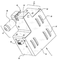
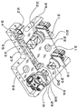
도 1은 본 발명의 제1 실시예의 제1 사시도이다. 이 도면에 도시된 바와 같이, 본 발명은 본 발명의 다른 구성요소 둘레에 인클로저를 형성하는 하우징으로 구성된다. 하우징은 상단 커버(2), 측벽(3) 및 바닥(도시되지 않음)을 갖는다. 상단 커버(2)는 임의의 방식으로 측벽(3)에 부착, 고정 또는 연결되거나 결합될 수 있으며; 여기에서 측벽(3)에 나사로 부착된 것으로 도시되어 있지만, 본 발명은 상단 커버(2)를 측벽(3)에 부착하는 그러한 특정 방식으로 제한되지 않는다. 대안 실시예에서, 상단 커버(2)와 측벽(3)은 일체로 몰딩되거나(동일한 부품의 일부) 함께 용접될 수 있다. 하우징(1)은 임의의 적절한 내구성 및 강성 재료(예를 들어, 알루미늄)로 제조될 수 있다. 바람직한 실시예에서, 상단 커버(2)는 열 소산을 위한 하나 이상의 통기구(5)로 구성된다.1 is a first perspective view of a first embodiment of the present invention. As shown in this figure, the invention consists of a housing forming an enclosure around other components of the invention. The housing has a top cover 2,
도 1은 제1 USB(6)를 또한 도시한다. 본 발명에서, 3개의 MEMS 미러(도시되지 않음) 각각에 대해 하나의 USB가 존재한다. 하우징(1)은 바람직하게는 대물 렌즈(8)가 메인 윈도우(9)의 제1 측면에 접근하게 하도록 크기 및 형상이 충분한 제1 앨코브(7) 및 대물 렌즈 터릿 또는 카메라/접안 렌즈(도시 생략)가 메인 윈도우(9)의 제2 측면에 접근하게 하도록 크기 및 형상이 충분한 제2 앨코브(10)를 형성하도록 구성된다. 하우징(1)의 상단 커버(2) 및 바닥(4)(도 5b 참조)은 바람직하게는 평탄하고, 측벽은 상단 커버(2)와 바닥(4) 사이에 위치되고 각각에 대해 수직이다. 2개의 앨코브(7, 10)는 메인 윈도우(9)가 위치된 하우징(1)의 연장부(11)를 형성한다. 메인 윈도우(9)는 연장부(11)의 전체 전방 단부를 가로질러 연장되고 연장부(11)의 양 측면 둘레를 감싸서 대물 렌즈(8) 및 대물 렌즈 터릿(도시되지 않음)이 윈도우의 반대쪽으로부터 메인 윈도우(9)에 접근하게 한다(이에 따라, 대물 렌즈와 대물 렌즈 터릿은 길이방향으로 서로 정렬됨).1 also shows a
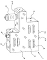
도 2는 본 발명의 제1 실시예의 제2 사시도이다. 이 도면은 제2 및 제3 MEMS 미러(도시되지 않음)에 대응하는 제2 및 제3 USB(12, 13)를 각각 도시한다. 3개의 USB(6, 12, 13)는 모두 하우징(1)의 측벽(3)에 있는 절결부를 통해 연장된다. 각 USB는 하우징 내부의 MEMS 미러에 근접하여 위치되고(도 5 참조) 3개의 MEMS 미러 중 하나에 구동 신호를 제공한다. 인쇄 회로 보드(14)는 3개의 MEMS 미러 각각에 대응하고(도 3 참조), 각 인쇄 회로 보드의 전력은 USB 아래 하우징의 구멍을 통해 공급된다(예를 들어, 도 7 참조).2 is a second perspective view of the first embodiment of the present invention. This figure shows the second and
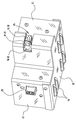
도 3은 하우징의 상단 커버가 제거된 것을 제외하고는 도 1에 도시된 것과 동일한 도면이다. 이 도면은 MEMS 미러(도 5 참조)를 각각 제어하는 3개의 인쇄 회로 보드(14)를 도시한다. 미래의 실시예에서, 단일의 인쇄 회로 보드로 3개의 MEMS 미러를 모두 제어하는 것이 가능할 수 있다.3 is the same view as shown in FIG. 1, except that the top cover of the housing is removed. This figure shows three printed
도 4는 인쇄 회로 보드가 제거된 경우를 제외하고 도 3에 도시된 것과 동일한 도면이다. 이 도면에 도시된 바와 같이, 복수의 스페이서(15)는 바람직하게는 장착 보드(16)와 인쇄 회로 보드(14) 사이에서 하나 이상의 장착 보드(16)의 상단에 위치된다. 장착 보드(16)는 인쇄 회로 보드(14) 아래에 위치되고, 스페이서(15)의 목적은 인쇄 회로 보드(14)가 장착 보드(16)와 전기적으로 접촉하지 않는 것을 보장하는 것이다. 장착 보드(16)의 구멍(17)은 전기 배선이 아래의 USB(13)로부터 장착 보드(16)를 통해 인쇄 회로 보드(14)로 나아가게 한다.Fig. 4 is the same view as that shown in Fig. 3, except that the printed circuit board is removed. As shown in this figure, a plurality of
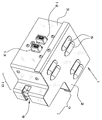
도 5는 스페이서 및 장착판이 제거된 것을 제외하고는 도 4에 도시된 것과 동일한 도면이다. 이 도면에 도시된 바와 같이, 본 발명은 3개의 MEMS 미러(18, 19, 20)를 포함하며, 이들 모두는 바람직하게는 원형이다. (도 5에서, 부품 번호 18, 19 및 20은 원형 미러가 테이프 또는 에폭시로 접착된 작은 정사각형 인쇄 회로 보드로서 도시되어 있다.) 본 발명은 바람직하게는 다양한 광학 구성요소가 적절하게 정렬되게 하는 내부 플랫폼(21)을 포함한다.FIG. 5 is the same view as shown in FIG. 4 except that the spacer and mounting plate are removed. As shown in this figure, the present invention includes three MEMS mirrors 18, 19, 20, all of which are preferably circular. (In FIG. 5, part numbers 18, 19 and 20 are shown as small square printed circuit boards in which a circular mirror is adhered with tape or epoxy.) The present invention is preferably an interior that allows various optical components to be properly aligned.
도 5a는 하우징의 측벽과 USB가 제거된 것을 제외하고는 도 5에 도시된 것과 동일한 도면이다. 내부 플랫폼(21)의 하나 이상의 구멍(22)은 본 발명이 광학 벤치에 나사로 고정되게 한다. 이 도면에 도시된 바와 같이, 제1 프리즘(23) 및 제1 프리즘(23)에 인접한 제2 프리즘(24)은 메인 윈도우(9)의 바로 내부에 위치된다. 여기에 도시되지 않았지만, 메인 윈도우(9)는 유리 또는 유사한 투명 재료로 덮일 수 있다. 제2 프리즘(24) 바로 후방에는 제1 고정 렌즈(25) 및 제2 고정 렌즈(26)로 구성된 광 릴레이가 있다. 제1 및 제2 고정 렌즈는 바람직하게는 하우징(1)의 바닥(4)의 슬롯(27) 내에 활주 가능하게 장착되고 고정 나사(도시되지 않음)로 제자리에 고정되어 그들 사이의 거리가 조절될 수 있다.FIG. 5A is the same view as shown in FIG. 5 except that the sidewalls and USB of the housing are removed. One or
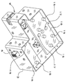
제2 고정 렌즈(26) 바로 후방에는 제1 빔스플리터(28)가 위치된다. 제1 빔스플리터(28)는, 제2 프리즘(24), 제1 고정 렌즈(25), 제2 고정 렌즈(26), 및 제1 빔스플리터(28)가 모두 광 릴레이의 길이방향 축을 따라 선형으로 정렬되도록 위치된다. 파장판(29)은 제1 빔스플리터(28)와 제1 MEMS 미러(18) 사이에 위치된다. 제1 및 제2 MEMS 미러(18, 19)는 광 릴레이의 길이방향 축에 대해 90도 각도로 서로 선형으로 정렬된다. 제2 빔스플리터(30)는 제2 MEMS 미러(19) 전방에 위치되고, 파장판(29)은 제2 빔스플리터(30)와 제2 MEMS 미러(19) 사이에 위치된다. 제3 MEMS 미러(20)는 메인 윈도우(9)에 근접하여 위치된다. 제3 고정 렌즈(31)는 제3 MEMS 미러(20)의 바로 전방에 위치되고, 파장판(29)은 제3 고정 렌즈(31)의 바로 전방에 위치된다. 본 발명은 가능한 한 작게 설계되어 상당한 벌크 없이 기존 현미경에 부착될 수 있다. 바람직한 실시예에서, 제3 고정 렌즈(31)(양의 고정 초점 길이 렌즈)의 추가는 1차 광학 요소의 길이를 4 인치 미만으로 유지할 수 있게 한다. 대안 실시예에서, 제3 고정 렌즈(31)는 제1 프리즘(23)과 제3 프리즘(33) 사이에 위치 설정된다. 다른 대안 실시예에서, 제3 고정 렌즈(31)는 제2 빔스플리터(30)와 제3 빔스플리터(32) 사이에 위치 설정된다. 제3 고정 렌즈(31)는 위치되는 곳에 따라 상이한 초점 길이를 가질 것이지만, 이 초점 길이는 아래에 제시된 수학식을 사용하여 계산될 수 있다.The
도 5a를 참조하면, 제3 빔스플리터(32)는 제3 고정 렌즈(31)의 전방에 있는 파장판(29)의 바로 전방에 위치되고, 제3 프리즘(33)은 제3 빔스플리터(32)의 바로 전방에 위치된다. 제3 MEMS 미러(20), 제3 고정 렌즈(31), 파장판(29), 제3 빔스플리터(32), 및 제3 프리즘(33)은 모두 광 릴레이의 길이방향 축에 대해 90도 각도로 서로 선형으로 정렬된다. 제3 프리즘(33)은 (2개의 고정 렌즈(25, 26) 사이에서) 광 릴레이의 중앙 섹션에 맞닿고, 이들 2개의 프리즘의 선형 정렬이 광 릴레이의 길이방향 축에 평행하도록 제1 프리즘(23)과 선형으로 또한 정렬된다. 제1, 제2 및 제3 빔스플리터(28, 30 및 32)는 모두 바람직하게는 편광 빔스플리터이다. 바람직한 실시예에서, 제1 및 제2 MEMS 미러(18, 19) 사이의 거리는 제2 및 제3 MEMS 미러(19, 20) 사이의 거리보다 작다. 이 구성은 도 6에 또한 도시되어 있다.Referring to FIG. 5A, the
도 6은 범용 직렬 버스(USB) 포트가 제거된 것을 제외하고는 도 5에 도시된 실시예의 평면도이다. 현미경은 투과 조명 및 반사 조명과 함께 사용할 수 있다(광은 시스템을 통해 전방으로 이동하고 시스템을 통해 카메라/접안 렌즈로 다시 반사되어 볼 수 있다). 본 발명에서, 카메라/접안 렌즈 및 대물 렌즈는 몇몇 상이한 위치에 배치될 수 있다. 하나의 가능한 구성에서, 카메라/접안 렌즈(또는 대물 렌즈 터릿)는 도 6의 "X" 위치에 위치되고, 대물 렌즈(투과를 위한 조명 소스를 제공하는)는 "Y" 위치에 위치된다(또한, 도 1 참조). 대안적으로, 카메라/접안 렌즈는 대물 렌즈가 "Y" 위치에 있는 상태에서 "Z" 위치에 위치될 수 있고; 이 구성에서, 제1 프리즘(23)이 제거된다. 또 다른 구성에서, 카메라/접안 렌즈는 "X" 위치에 있고 대물 렌즈는 "Z" 위치에 있으며; 이 구성에서, 제2 프리즘(24)이 제거된다. 그러한 모든 구성에서, 카메라/접안 렌즈는 반사를 위한 조명 소스를 제공할 수 있다. 다음 단락의 목적을 위해, 이들 3개의 구성을 각각 "구성 A", "구성 B" 및 "구성 C"로 지칭한다.6 is a plan view of the embodiment shown in FIG. 5, except that the Universal Serial Bus (USB) port is removed. The microscope can be used with transmitted and reflected illumination (light can travel forward through the system and be reflected back through the system to the camera / eyepiece). In the present invention, the camera / eyepiece and objective lens can be placed at several different positions. In one possible configuration, the camera / eyepiece (or objective lens turret) is positioned in the “X” position in FIG. 6, and the objective lens (which provides an illumination source for transmission) is positioned in the “Y” position (also , See FIG. 1). Alternatively, the camera / eyepiece may be positioned in the “Z” position with the objective lens in the “Y” position; In this configuration, the
구성 A에서, 광은 대물 렌즈(8)로부터 메인 윈도우(9)를 통해 이동하고 입사 광 빔에 45도 각도로 있는 제2 프리즘(24)에 부딪친다. 이어서, 광 빔은 제1 고정 렌즈(25) 및 제2 고정 렌즈(26)를 통해 지향되어 제1 빔스플리터(28)에 부딪친다. 이어서, 광은 파장판(29)을 통해 이동하고 제1 MEMS 미러(18)에 부딪치고, 제1 빔스플리터(28)를 통해 제2 빔스플리터(30)로 다시 반사된다. 그 후, 광 빔은 제2 MEMS 미러의 전방에서 파장판(29)을 통해 이동하고 제2 MEMS 미러(19)에 부딪치며, 파장판(29)을 통해 다시 제2 빔스플리터(30)로 반사된다. 이어서, 광 빔은 제2 빔스플리터(30)로부터 제3 빔스플리터(32)로 수직으로 지향된다. 이어서, 광은 제3 MEMS 미러(20)의 전방의 파장판(29)을 통해, 제3 고정 렌즈(31)를 통해, 그리고 제3 MEMS 미러(20) 상으로 이동한다. 그 후, 광 빔은 제3 고정 렌즈(31), 파장판(29), 및 제3 빔스플리터(32)를 통해 다시 반사되어 제3 프리즘(33)에 부딪치며, 제3 프리즘은 광 빔을 메인 윈도우(9)의 측면을 통해 제1 프리즘(23)으로 지향시키며, 메인 윈도우에서 광 빔은 "X" 위치에서 디바이스를 빠져나온다. 3개의 프리즘(23, 24, 33) 모두는 입사 광 빔이 45도 각도로 프리즘에 부딪치고 그 입사 방향에 대해 90도 각도로 재지향되도록 구성된다.In configuration A, light travels from the
광선이 MEMS 미러(18, 19 및 20)에 부딪침에 따라, 3개의 MEMS 미러의 디포커싱 및 구면 수차를 제어하는 소프트웨어를 통해 이들 3개의 지점 각각에서 배율 및/또는 초점에 영향을 줄 기회가 있다. 바람직한 실시예에서, 제1 MEMS 미러(18)는 1:1 보정 비율로 대물 렌즈의 후방 초점면에 직접 맵핑된다. 바람직한 실시예에서, 제3 MEMS 미러(20)는 더 큰 배율을 달성하기 위해 다른 2개의 MEMS 미러(18, 19)보다 큰 빔 직경을 갖는다.As the light strikes the MEMS mirrors 18, 19 and 20, there is an opportunity to influence the magnification and / or focus at each of these three points through software that controls the defocusing and spherical aberration of the three MEMS mirrors. . In a preferred embodiment, the
구성 B에서, 광 경로는, 제1 프리즘(23)의 제거와 함께 광이 도 6의 "Z" 위치에서 디바이스를 빠져나간다는 것을 제외하고는 구성 A에 대해 전술한 바와 동일하다. 이 구성에서, 카메라/접안 렌즈는 대물 렌즈(8)에 수직이다. 구성 C에서, 카메라/접안 렌즈는 또한 대물 렌즈(8)에 수직이지만, 제1 프리즘(23)이 아니라 제2 프리즘(24)이 제거된다. 광의 경로는 광이 메인 윈도우(9)의 전방을 통해 디바이스로 들어가서 광 릴레이의 제1 고정 렌즈(25)에 부딪치는 것을 제외하고, 구성 A에 대해 전술한 바와 동일하다.In configuration B, the light path is the same as described above for configuration A, except that with removal of the
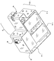
도 7은 도 1 및 도 2에 도시된 것과 동일한 실시예의 제3 사시도이다. 이 도면은 제1 프리즘(23) 및 제2 프리즘(24) 뿐만 아니라 제1 고정 렌즈(25)를 볼 수 있는 메인 윈도우(9)의 보다 명확한 도면을 제공한다. 제1 프리즘(23)에 부딪칠 때까지 광 빔은 직경이 더 크기 때문에, 제1 프리즘(23)의 직경은 제2 프리즘(24)의 직경보다 크다. 유사하게, MEMS 미러(20)의 직경은 더 큰 직경의 광 빔으로 인해 다른 2개의 MEMS 미러(18, 19)의 직경보다 크다.7 is a third perspective view of the same embodiment as shown in FIGS. 1 and 2. This figure provides a clearer view of the
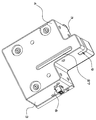
도 8은 대물 렌즈가 하우징에 직접 부착된 본 발명의 제2 실시예의 제1 사시도이고, 도 9는 대물 렌즈 터릿이 하우징에 직접 부착된 도 8에 도시된 실시예의 제2 사시도이다. 이 특정 실시예에서, 디바이스는 기존 현미경에 직접 부착될 수 있다. 도시된 바와 같이, 대물 렌즈(8)는 하우징(1)에 일체형인 제1 나사형 어댑터(34)를 통해 "Y" 위치(위치 지정은 도 6 참조)에서 하우징에 나사 결합된다. 대물 렌즈 터릿(도시되지 않음)은 또한 하우징(1)에 일체형인 제2 나사형 어댑터(35)를 통해 "X" 위치에서 하우징에 나사 결합된다. 메인 윈도우(9)는 제거되었고(대물 렌즈 및 대물 렌즈 터릿이 하우징에 직접 나사 결합되어 있기 때문에), 연장부(11)는 나사형 어댑터(34, 35)를 수용하도록 연장되었지만, 다른 모든 측면에서 본 발명은 이전에 설명되었다.8 is a first perspective view of a second embodiment of the present invention in which the objective lens is directly attached to the housing, and FIG. 9 is a second perspective view of the embodiment shown in FIG. 8 in which the objective lens turret is directly attached to the housing. In this particular embodiment, the device can be attached directly to an existing microscope. As shown, the
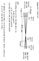
다음의 설명은 본 발명을 좌우하는 수학식에 관한 것이다. 도 10은 본 발명의 광학 레이아웃의 다이어그램이다. 1개의 고정 렌즈(F)(참조 번호 31) 및 3개의 다초점 렌즈(v1, v2 및 v3)(각각 참조 번호 20, 19 및 18)가 도시되어 있다. 고정 렌즈(F)와 다초점 렌즈(v1)는 결합될 수 있으며 G로 설명된다. 다초점 렌즈(v2 및 v3)는 결합될 수 있고 H로 설명된다. 거리(a)는 고정 초점 길이 렌즈(F)와 다초점 렌즈(v1) 사이의 간격을 나타낸다. 거리(b)는 다초점 렌즈(v1)와 다초점 렌즈(v2) 사이의 간격을 정의한다. 거리(b 및 c)는 양수이다. 거리(a)는 도시된 바와 같이 양수일 수 있으며, 여기에서 다초점 렌즈(v1)의 전방에 있다. 거리(a)는 또한 음수이고 다초점 렌즈(v1) 후방에 있을 수 있다. F에 대해 가장 쉽고 최상의 장소는 v1에 가까울 것으로 예상된다. 거리(a 및 c)는 시스템을 2-렌즈 릴레이로 고려하기에 충분히 작은 것으로 추정된다. G 및 H에 대한 등가 초점 길이, fG 및 fH는 각각 다음과 같다:The following description relates to equations that influence the present invention. 10 is a diagram of the optical layout of the present invention. One fixed lens F (reference numeral 31) and three multifocal lenses v1, v2 and v3 (
![]()
![]()
여기서, fF, fv1, fv2, 및 fv3은 각각 렌즈(F, v1, v2 및 v3)의 초점 길이이다. 거리가 무한 컨쥬게이트 촬상 또는 b = fG + fH를 제공한다고 가정하면, 제2 앨코브(10)에서 관찰된 샘플의 배율 M은 다음과 같다:Here, f F , f v1 , f v2 , and f v3 are the focal lengths of the lenses F, v1, v2, and v3, respectively. Assuming that the distance provides infinite conjugate imaging or b = f G + f H , the magnification M of the sample observed in the
![]()
![]()
제1 MEMS 미러(18)(v3)의 6 mm 직경은 대부분의 0.8 NA 대물 렌즈의 후방 애퍼처의 직경과 1:1 스케일로 일치하며 본 발명에 대한 애퍼처 스톱(aperture stop)으로서 작용한다. 이는 MEMS 미러 형상을 미세하게 제어하여 시스템의 구면 수차 및 기타 수차를 쉽게 보정하게 한다. 또한, 전체 시스템의 애퍼처 스톱이 대물 렌즈의 최대 애퍼처가 되도록 하여 동적 초점 범위에 걸쳐 분해능이 유지되는 것이 보장된다.The 6 mm diameter of the first MEMS mirror 18 (v3) matches the diameter of the rear aperture of most 0.8 NA objective lenses on a 1: 1 scale and serves as an aperture stop for the present invention. This makes it easy to correct spherical aberration and other aberrations in the system by finely controlling the MEMS mirror shape. In addition, it is ensured that the aperture stop of the entire system is the maximum aperture of the objective lens, so that the resolution is maintained over the dynamic focus range.
6 mm MEMS 미러는 60 mm에서 무한대까지의 초점 길이를 가질 수 있다. 바람직한 실시예에서, 제1 및 제2 MEMS 미러(18, 19)는 fv2 = fv3 = 60 mm에 있다. 그들 사이의 간격(c)은 빔스플리터 및 파장판의 크기로 인해 적어도 20 mm이다. 위에 제시한 식을 사용하여, fH = (60*60)/(60+60-20) = 36 mm이다. 2의 배율의 경우, M = fG/36 = 2 또는 fG = 72 mm이다. 제3 MEMS 미러(20)는 2배 배율의 경우 MEMS 미러(18, 19)의 직경의 2배를 가져야 하고; 따라서, 그 직경은 12 mm이다. MEMS 미러(20)는 200 mm 내지 무한대의 초점 길이 범위를 갖는다. 바람직한 실시예에서, 값 fv1 = 600 mm은 2배 배율의 경우에 고정 렌즈(F)의 광 파워를 감소시키도록 선택되어 도입된 수차를 최소화시킨다. 통상적으로, 고정 렌즈가 더 많은 광 파워를 가질수록, 시스템에 도입되는 수차가 더 많아진다. 초점 길이에 대한 600 mm의 값fv1은 또한 fG의 감소를 더 줄임으로써 시스템의 배율이 감소되게 한다. 제3 고정 렌즈(31)를 선택하기 위해, fG = 72 mm이고, 고정 초점 길이 렌즈(31)와 v1 사이의 간격(a)은 적어도 5 mm이라고 가정한다; fG = 72 mm = fF * 600/(fF+600-5)를 해결하면, fG = 82이다. 바람직한 실시예에서, fG와 fH 사이의 거리는 유닛의 전체 크기를 비교적 작게 유지하기 위해 100 mm 미만이다.The 6 mm MEMS mirror can have a focal length from 60 mm to infinity. In a preferred embodiment, the first and second MEMS mirrors 18, 19 are at f v2 = f v3 = 60 mm. The distance (c) between them is at least 20 mm due to the size of the beamsplitter and wave plate. Using the formula presented above, f H = (60 * 60) / (60 + 60-20) = 36 mm. For a magnification of 2, M = f G / 36 = 2 or f G = 72 mm. The
도 11에 도시된 광학 트레인은 1개의 12 mm(v1) 및 2개의 6 mm(v2 및v3) MEMS 미러를 포함하고; 도면에 대한 이전의 설명을 참조하면, 더 큰 MEMS 미러는 제3 MEMS 미러(20)이고, 2개의 더 작은 MEMS 미러는 제1 및 제2 MEMS 미러(18, 19)이다. 2개의 릴레이 렌즈(제1 및 제2 고정 렌즈 25, 26)는 MEMS 미러(18)(v3)를 대물 렌즈의 후방 초점면 상에 1:1 스케일로 촬상하며, 이는 구면 수차의 용이한 보정을 허용한다. (후방 초점면은 일반적으로 대물 렌즈 내에 있으며, 광 릴레이는 거기에 컨쥬게이트 이미지 평면을 정확하게 배치하게 한다.) 이 릴레이를 따른 2개의 고정 렌즈의 배치(즉, 그들 사이의 거리)는 디바이스가 인터페이싱되는 현미경 및 2개의 릴레이 렌즈의 파워에 따라 좌우된다.The optical train shown in FIG. 11 includes one 12 mm (v1) and two 6 mm (v2 and v3) MEMS mirrors; Referring to the previous description of the figures, the larger MEMS mirror is the
여기에 설명된 시스템은 Zemax, LLC의 OPTICSTUDIO® 광학 시험 플랫폼에서 모델링되었다. 표 1은 0.8 NA의 수성 샘플에서 연속 207-미크론 범위에 걸쳐 몇 가지 초점 위치를 나타낸다. 이 표는 또한 연속 1-2 배 범위에 걸쳐 가능한 몇 가지 배율을 나타낸다.The system described here was modeled on Zemax, LLC's OPTICSTUDIO® optical test platform. Table 1 shows several focal positions over a continuous 207-micron range in an aqueous sample of 0.8 NA. The table also shows some possible magnifications over a continuous 1-2 times range.

본 발명은 소량의 디포커싱에 대한 미세한 제어를 가능하게 할 뿐만 아니라 0.8 개구수에서 200 μm 초과 초점 범위 또는 0.2 NA에서 800 μm 초과 초점 범위를 제공한다.The present invention not only enables fine control of small amounts of defocusing, but also provides a focus range of greater than 200 μm at 0.8 numerical aperture or a focus range of greater than 800 μm at 0.2 NA.
현재, 기존의 MEMS 미러는 전자적으로 활성화하기 위해 약 100-150 볼트를 필요로 한다. MEMS 미러는 벤치-탑 고전압 전원으로 구동될 수 있다. 바람직한 실시예에서, 고전압 부스트 컨버터가 사용되어 USB 전력으로부터 MEMS 미러를 구동시킨다.Currently, existing MEMS mirrors require about 100-150 volts to activate electronically. MEMS mirrors can be driven by bench-top high voltage power supplies. In a preferred embodiment, a high voltage boost converter is used to drive the MEMS mirror from USB power.
본 발명은 비전문가가 샘플 스테이지 또는 대물 렌즈의 움직임 없이 광시야, 공초점 또는 다광자 현미경으로 빠른 포커싱 및 줌을 수행하게 한다는 점에서 종래 기술에 비해 큰 개선이다. 본 발명의 이점은 다음을 포함하지만 이것으로 제한되지 않는다: (a) 포커싱 및 줌이 모두 기구 내에서 광학적으로 수행되는 동안 샘플이 정지 상태로 유지되고; (b) 큰 질량체의 병진이 없으므로, 시스템 진동이 최소화되며; (c) 초점 및 줌이 독립적으로 제어될 수 있고; (d) (종래 기술과 비교하여) 비교적 큰 포커싱 및 줌이 작은 폼 팩터에서 달성되며; (e) 대물 렌즈의 후방 애퍼처는 초점 및 줌 범위에 걸쳐 채워져서, 고분해능 촬상을 유지하고; (f) 가변적이고 연속적인 초점 속도가 가능하며; (g) MEMS 미러는 포커싱을 위해 1 kHz 초과의 속도로 작동하며, 정밀하고 지속적인 초점 제어를 제공할 수 있다.The present invention is a significant improvement over the prior art in that it allows non-experts to perform fast focusing and zooming with a wide field of view, confocal or multiphoton microscope without movement of the sample stage or objective lens. Advantages of the present invention include, but are not limited to: (a) the sample remains stationary while both focusing and zooming are performed optically in the instrument; (b) there is no large mass translation, so system vibration is minimized; (c) focus and zoom can be controlled independently; (d) relatively large focusing and zooming (compared to prior art) is achieved in a small form factor; (e) the rear aperture of the objective lens is filled over the focus and zoom range, maintaining high resolution imaging; (f) variable and continuous focus speeds are possible; (g) MEMS mirrors operate at speeds above 1 kHz for focusing and can provide precise and continuous focus control.
본 발명의 미래의 실시예는, 초점 및/또는 줌의 음성 활성화 제어, 사용자가 손을 자유롭게 유지할 수 있도록 줌을 제어하기 위한 풋 스텝 버튼, MEMS 미러 상의 동심 링으로 저차 및 고차 구면 수차를 제어하기 위한 소프트웨어, 미세한 비대칭 형상 제어를 갖는 가변 렌즈로 다른 수차를 제어하기 위한 소프트웨어, 및 타임 랩스 실험 중 자동 초점을 위한 소프트웨어를 포함할 수 있다.Future embodiments of the present invention include controlling voice activation of focus and / or zoom, foot step buttons to control zoom to allow the user to keep their hands free, and controlling low and high order spherical aberration with concentric rings on the MEMS mirror. Software, software for controlling different aberrations with a variable lens having fine asymmetrical shape control, and software for autofocus during a time-lapse experiment.
본 발명의 바람직한 실시예가 도시되고 설명되었지만, 본 기술 분야의 숙련자에게는 더 넓은 양태에서 본 발명을 벗어나지 않고 많은 변경 및 수정이 이루어질 수 있음이 명백할 것이다. 따라서, 첨부된 청구범위는 본 발명의 진정한 사상 및 범위 내에 있는 그러한 모든 변경 및 수정을 포함하도록 의도된다.Although preferred embodiments of the invention have been shown and described, it will be apparent to those skilled in the art that many changes and modifications can be made without departing from the invention in its broader aspects. Accordingly, the appended claims are intended to cover all such changes and modifications that fall within the true spirit and scope of the invention.
인용 문헌Cited literature
1. Lukes, S.J., 및 Dickensheets, D.L., SPIE BiOS, International Society for Optics and Photonics, 2014, pp. 89490W-89411.One. Lukes, S.J., and Dickensheets, D.L., SPIE BiOS, International Society for Optics and Photonics, 2014, pp. 89490W-89411.
Claims (44)
(a) 하우징 내에 위치된 제1 MEMS 미러, 제2 MEMS 미러, 및 제3 MEMS 미러;
(b) 상기 제1 MEMS 미러에 근접하여 위치되고 구동 신호를 제공하도록 구성된 제1 범용 직렬 버스, 제2 MEMS 미러에 근접하여 위치되고 구동 신호를 제공하도록 구성된 제2 범용 직렬 버스, 및 제3 MEMS 미러에 근접하여 위치되고 구동 신호를 제공하도록 구성된 제3 범용 직렬 버스;
(c) 제1 MEMS 미러, 제2 MEMS 미러, 및 제3 MEMS 미러를 제어하도록 구성된 적어도 하나의 인쇄 회로 보드;
(d) 제1 프리즘 및 제1 프리즘에 인접하여 위치된 제2 프리즘;
(e) 제1 고정 렌즈 및 제2 고정 렌즈로 구성되고, 제2 프리즘의 바로 후방에 위치된 광 릴레이;
(f) 제2 고정 렌즈의 바로 후방에 위치된 제1 빔스플리터; 및
(g) 상기 제2 MEMS 미러의 전방에 위치된 제2 빔스플리터를 포함하고,
제2 프리즘, 제1 고정 렌즈, 제2 고정 렌즈, 및 제1 빔스플리터는 광 릴레이의 길이방향 축을 따라 선형으로 정렬되며,
제1 MEMS 미러 및 제2 MEMS 미러는 광 릴레이의 길이방향 축에 대해 90도 각도로 서로 선형으로 정렬되는, 동적 초점 및 줌 시스템.Dynamic focus and zoom system for use with wide field of view, confocal and multiphoton microscopes,
(a) a first MEMS mirror, a second MEMS mirror, and a third MEMS mirror positioned within the housing;
(b) a first universal serial bus positioned adjacent to the first MEMS mirror and configured to provide a drive signal, a second universal serial bus positioned adjacent to the second MEMS mirror and configured to provide a drive signal, and a third MEMS A third universal serial bus located close to the mirror and configured to provide a drive signal;
(c) at least one printed circuit board configured to control the first MEMS mirror, the second MEMS mirror, and the third MEMS mirror;
(d) a first prism and a second prism positioned adjacent to the first prism;
(e) an optical relay composed of a first fixed lens and a second fixed lens, positioned directly behind the second prism;
(f) a first beamsplitter located directly behind the second fixed lens; And
(g) a second beamsplitter located in front of the second MEMS mirror,
The second prism, the first fixed lens, the second fixed lens, and the first beamsplitter are linearly aligned along the longitudinal axis of the optical relay,
A dynamic focus and zoom system, wherein the first MEMS mirror and the second MEMS mirror are linearly aligned with each other at a 90 degree angle to the longitudinal axis of the optical relay.
상기 제3 프리즘은 제1 프리즘과 제3 프리즘의 선형 정렬이 광 릴레이의 길이방향 축에 평행하도록 제1 프리즘과 선형으로 정렬되는, 동적 초점 및 줌 시스템.13. The method of claim 12, wherein the third prism abuts the central section of the optical relay between the first fixed lens and the second fixed lens,
Wherein the third prism is aligned linearly with the first prism such that the linear alignment of the first prism and the third prism is parallel to the longitudinal axis of the optical relay.
(a) 하우징 내에 위치된 제1 MEMS 미러, 제2 MEMS 미러, 및 제3 MEMS 미러;
(b) 제1 프리즘 및 제1 프리즘에 인접하여 위치된 제2 프리즘;
(c) 제1 고정 렌즈 및 제2 고정 렌즈로 구성되고, 제2 프리즘의 바로 후방에 위치된 광 릴레이;
(d) 제2 고정 렌즈의 바로 후방에 위치된 제1 빔스플리터; 및
(e) 상기 제2 MEMS 미러의 전방에 위치된 제2 빔스플리터를 포함하고,
제2 프리즘, 제1 고정 렌즈, 제2 고정 렌즈, 및 제1 빔스플리터는 광 릴레이의 길이방향 축을 따라 선형으로 정렬되며,
제1 MEMS 미러 및 제2 MEMS 미러는 광 릴레이의 길이방향 축에 대해 90도 각도로 서로 선형으로 정렬되는, 동적 초점 및 줌 시스템.Dynamic focus and zoom system for use with wide field of view, confocal and multiphoton microscopes,
(a) a first MEMS mirror, a second MEMS mirror, and a third MEMS mirror positioned within the housing;
(b) a first prism and a second prism positioned adjacent to the first prism;
(c) an optical relay consisting of a first fixed lens and a second fixed lens, positioned directly behind the second prism;
(d) a first beamsplitter located directly behind the second fixed lens; And
(e) a second beamsplitter located in front of the second MEMS mirror,
The second prism, the first fixed lens, the second fixed lens, and the first beamsplitter are linearly aligned along the longitudinal axis of the optical relay,
A dynamic focus and zoom system, wherein the first MEMS mirror and the second MEMS mirror are linearly aligned with each other at a 90 degree angle to the longitudinal axis of the optical relay.
상기 제3 프리즘은 제1 프리즘과 제3 프리즘의 선형 정렬이 광 릴레이의 길이방향 축에 평행하도록 제1 프리즘과 선형으로 정렬되는, 동적 초점 및 줌 시스템.34. The method of claim 33, wherein the third prism abuts the central section of the optical relay between the first fixed lens and the second fixed lens,
Wherein the third prism is aligned linearly with the first prism such that the linear alignment of the first prism and the third prism is parallel to the longitudinal axis of the optical relay.
(a) 하우징 내에 위치된 제1 MEMS 미러, 제2 MEMS 미러, 및 제3 MEMS 미러;
(b) 제1 프리즘;
(c) 제1 고정 렌즈 및 제2 고정 렌즈로 구성되고, 제1 프리즘의 바로 후방에 위치된 광 릴레이;
(d) 제2 고정 렌즈의 바로 후방에 위치된 제1 빔스플리터; 및
(e) 상기 제2 MEMS 미러의 전방에 위치된 제2 빔스플리터를 포함하고,
제1 프리즘, 제1 고정 렌즈, 제2 고정 렌즈, 및 제1 빔스플리터는 광 릴레이의 길이방향 축을 따라 선형으로 정렬되며,
제1 MEMS 미러 및 제2 MEMS 미러는 광 릴레이의 길이방향 축에 대해 90도 각도로 서로 선형으로 정렬되는, 동적 초점 및 줌 시스템.Dynamic focus and zoom system for use with wide field of view, confocal and multiphoton microscopes,
(a) a first MEMS mirror, a second MEMS mirror, and a third MEMS mirror positioned within the housing;
(b) a first prism;
(c) an optical relay composed of a first fixed lens and a second fixed lens, positioned directly behind the first prism;
(d) a first beamsplitter located directly behind the second fixed lens; And
(e) a second beamsplitter located in front of the second MEMS mirror,
The first prism, the first fixed lens, the second fixed lens, and the first beamsplitter are linearly aligned along the longitudinal axis of the optical relay,
A dynamic focus and zoom system, wherein the first MEMS mirror and the second MEMS mirror are linearly aligned with each other at a 90 degree angle to the longitudinal axis of the optical relay.
(a) 하우징 내에 위치된 제1 MEMS 미러, 제2 MEMS 미러, 및 제3 MEMS 미러;
(b) 제1 고정 렌즈 및 제2 고정 렌즈로 구성된 광 릴레이;
(c) 상기 광 릴레이의 제1 단부로부터 오프셋되어 위치된 제1 프리즘;
(d) 제2 고정 렌즈의 바로 후방에 위치된 제1 빔스플리터; 및
(e) 상기 제2 MEMS 미러의 전방에 위치된 제2 빔스플리터를 포함하고,
제1 고정 렌즈, 제2 고정 렌즈, 및 제1 빔스플리터는 광 릴레이의 길이방향 축을 따라 선형으로 정렬되며;
제1 MEMS 미러 및 제2 MEMS 미러는 광 릴레이의 길이방향 축에 대해 90도 각도로 서로 선형으로 정렬되는, 동적 초점 및 줌 시스템.Dynamic focus and zoom system for use with wide field of view, confocal and multiphoton microscopes,
(a) a first MEMS mirror, a second MEMS mirror, and a third MEMS mirror positioned within the housing;
(b) an optical relay composed of a first fixed lens and a second fixed lens;
(c) a first prism positioned offset from the first end of the optical relay;
(d) a first beamsplitter located directly behind the second fixed lens; And
(e) a second beamsplitter located in front of the second MEMS mirror,
The first fixed lens, the second fixed lens, and the first beamsplitter are linearly aligned along the longitudinal axis of the optical relay;
A dynamic focus and zoom system, wherein the first MEMS mirror and the second MEMS mirror are linearly aligned with each other at a 90 degree angle to the longitudinal axis of the optical relay.
Applications Claiming Priority (3)
| Application Number | Priority Date | Filing Date | Title |
|---|---|---|---|
| US15/706,331 US10416429B2 (en) | 2017-09-15 | 2017-09-15 | Dynamic focus and zoom system for use with wide-field, confocal and multiphoton microscopes |
| US15/706,331 | 2017-09-15 | ||
| PCT/US2018/041176 WO2019055106A1 (en) | 2017-09-15 | 2018-07-08 | Dynamic focus and zoom system for use with wide-field, confocal and multiphoton microscopes |
Publications (2)
| Publication Number | Publication Date |
|---|---|
| KR20200054255A true KR20200054255A (en) | 2020-05-19 |
| KR102625431B1 KR102625431B1 (en) | 2024-01-17 |
Family
ID=65720178
Family Applications (1)
| Application Number | Title | Priority Date | Filing Date |
|---|---|---|---|
| KR1020207010627A KR102625431B1 (en) | 2017-09-15 | 2018-07-08 | Dynamic focus and zoom system for use with widefield, confocal, and multiphoton microscopes |
Country Status (6)
| Country | Link |
|---|---|
| US (1) | US10416429B2 (en) |
| EP (1) | EP3682285B1 (en) |
| JP (1) | JP7025530B2 (en) |
| KR (1) | KR102625431B1 (en) |
| CN (1) | CN111065950B (en) |
| WO (1) | WO2019055106A1 (en) |
Families Citing this family (3)
| Publication number | Priority date | Publication date | Assignee | Title |
|---|---|---|---|---|
| KR101903406B1 (en) * | 2015-02-16 | 2018-11-07 | 삼성중공업 주식회사 | Device for Purifying Exhaust and Vessel having the Same |
| US20210208178A1 (en) * | 2020-01-02 | 2021-07-08 | Baker Hughes Oilfield Operations Llc | Motion, vibration and aberrant condition detection and analysis for rotating shafts, reciprocating machines, turbomachinery, pipes, pipelines, and related machinery |
| CN113579468B (en) * | 2021-07-28 | 2022-07-15 | 杭州爱新凯科技有限公司 | Linear array type laser 3D printing device and method |
Citations (6)
| Publication number | Priority date | Publication date | Assignee | Title |
|---|---|---|---|---|
| JP2005017282A (en) * | 2003-05-30 | 2005-01-20 | Olympus Corp | Light-receiving unit and measuring apparatus including the same |
| JP3655677B2 (en) * | 1995-11-08 | 2005-06-02 | オリンパス株式会社 | Confocal scanning optical microscope |
| US20100149073A1 (en) * | 2008-11-02 | 2010-06-17 | David Chaum | Near to Eye Display System and Appliance |
| US8585567B2 (en) * | 2007-12-11 | 2013-11-19 | Tokitae Llc | Systems, devices, and methods including paramagnetic oscillation, rotation and translation of hemozoin asymmetric nanoparticles in response to multi-harmonic optical detection of the presence of hemozoin |
| US20170261737A1 (en) * | 2014-12-10 | 2017-09-14 | Canon Kabushiki Kaisha | Slide and microscope system using the slide |
| US9891422B2 (en) * | 2012-09-12 | 2018-02-13 | Washington State University | Digital confocal optical profile microscopy |
Family Cites Families (19)
| Publication number | Priority date | Publication date | Assignee | Title |
|---|---|---|---|---|
| US6647172B2 (en) * | 2001-06-29 | 2003-11-11 | Lucent Technologies Inc. | Imaging technique for use with optical MEMS devices |
| JP2004212355A (en) * | 2003-01-09 | 2004-07-29 | Hitachi Ltd | Biological electron microscope and method of sample observation |
| JP4125648B2 (en) * | 2003-08-11 | 2008-07-30 | 大倉インダストリー株式会社 | Line-shaped light beam generator and laser microscope |
| US7057826B2 (en) * | 2004-03-22 | 2006-06-06 | Angstrom Inc. | Small and fast zoom system |
| US7215882B2 (en) * | 2004-07-21 | 2007-05-08 | Angatrom, Inc. | High-speed automatic focusing system |
| JP2006133499A (en) * | 2004-11-05 | 2006-05-25 | Shimadzu Corp | Confocal scanner and confocal microscope |
| US7593156B2 (en) * | 2005-08-26 | 2009-09-22 | Leica Microsystems (Schweiz) Ag | Microscope with micro-mirrors for optional deflection and/or beam splitting |
| US7864996B2 (en) | 2006-02-17 | 2011-01-04 | Lucid, Inc. | System for macroscopic and confocal imaging of tissue |
| DE102008041819A1 (en) * | 2008-09-04 | 2010-03-11 | Leica Microsystems (Schweiz) Ag | Optical imaging system |
| WO2010060622A2 (en) | 2008-11-26 | 2010-06-03 | Carl Zeiss Surgical Gmbh | Imaging system |
| US8425037B2 (en) | 2010-07-30 | 2013-04-23 | Adventus Technologies, Inc. | Intraoperative imaging system and apparatus |
| US9050027B2 (en) | 2010-07-30 | 2015-06-09 | Adventus Technologies, Inc. | Intraoperative imaging system and apparatus |
| US9256009B2 (en) | 2011-09-22 | 2016-02-09 | TAG Optics Inc. | Tunable acoustic gradient index of refraction lens and system |
| WO2013131719A1 (en) * | 2012-03-08 | 2013-09-12 | Lemoptix Sa | A mems micro-mirror assembly |
| CN102621117B (en) * | 2012-03-09 | 2014-03-12 | 福建师范大学 | Living cell laser scanning co-focusing microscope imaging system |
| US9629523B2 (en) | 2012-06-27 | 2017-04-25 | Camplex, Inc. | Binocular viewing assembly for a surgical visualization system |
| DE102014107606A1 (en) | 2014-05-28 | 2015-12-03 | Carl Zeiss Ag | Function-integrated laser scanning microscope |
| US9602715B2 (en) | 2015-07-09 | 2017-03-21 | Mitutoyo Corporation | Adaptable operating frequency of a variable focal length lens in an adjustable magnification optical system |
| CN108845410B (en) * | 2018-07-03 | 2021-01-22 | 上海理工大学 | Multi-beam confocal high-speed scanning imaging method and device based on polyhedral prism |
-
2017
- 2017-09-15 US US15/706,331 patent/US10416429B2/en active Active
-
2018
- 2018-07-08 EP EP18855517.1A patent/EP3682285B1/en active Active
- 2018-07-08 CN CN201880058942.1A patent/CN111065950B/en active Active
- 2018-07-08 WO PCT/US2018/041176 patent/WO2019055106A1/en unknown
- 2018-07-08 JP JP2020513328A patent/JP7025530B2/en active Active
- 2018-07-08 KR KR1020207010627A patent/KR102625431B1/en active IP Right Grant
Patent Citations (6)
| Publication number | Priority date | Publication date | Assignee | Title |
|---|---|---|---|---|
| JP3655677B2 (en) * | 1995-11-08 | 2005-06-02 | オリンパス株式会社 | Confocal scanning optical microscope |
| JP2005017282A (en) * | 2003-05-30 | 2005-01-20 | Olympus Corp | Light-receiving unit and measuring apparatus including the same |
| US8585567B2 (en) * | 2007-12-11 | 2013-11-19 | Tokitae Llc | Systems, devices, and methods including paramagnetic oscillation, rotation and translation of hemozoin asymmetric nanoparticles in response to multi-harmonic optical detection of the presence of hemozoin |
| US20100149073A1 (en) * | 2008-11-02 | 2010-06-17 | David Chaum | Near to Eye Display System and Appliance |
| US9891422B2 (en) * | 2012-09-12 | 2018-02-13 | Washington State University | Digital confocal optical profile microscopy |
| US20170261737A1 (en) * | 2014-12-10 | 2017-09-14 | Canon Kabushiki Kaisha | Slide and microscope system using the slide |
Also Published As
| Publication number | Publication date |
|---|---|
| KR102625431B1 (en) | 2024-01-17 |
| CN111065950A (en) | 2020-04-24 |
| JP7025530B2 (en) | 2022-02-24 |
| JP2020535456A (en) | 2020-12-03 |
| US20190086655A1 (en) | 2019-03-21 |
| CN111065950B (en) | 2022-05-03 |
| EP3682285A4 (en) | 2021-06-16 |
| WO2019055106A1 (en) | 2019-03-21 |
| US10416429B2 (en) | 2019-09-17 |
| EP3682285A1 (en) | 2020-07-22 |
| EP3682285B1 (en) | 2022-10-05 |
Similar Documents
| Publication | Publication Date | Title |
|---|---|---|
| US10168519B2 (en) | Light sheet generator | |
| CN106461926B (en) | Light scanning microscope with simplified optics, in particular with variable pupil position | |
| KR102625431B1 (en) | Dynamic focus and zoom system for use with widefield, confocal, and multiphoton microscopes | |
| US20210239961A1 (en) | Method for generating an overview image using a large aperture objective | |
| US20130070339A1 (en) | Method and device for image stabilization in an optical observation or measurement instrument | |
| US5764408A (en) | Lens-barrel optical system and microscope apparatus | |
| KR20200096238A (en) | Microscope with function module and function module | |
| WO1991015150A1 (en) | Apparatus for observation of the eye, comprising means for reversing the image | |
| US10466461B2 (en) | Dynamic focus and zoom system for use with wide-field, confocal and multiphoton microscopes | |
| JP3534733B2 (en) | Fixed high magnification switching microscope | |
| JP6945557B2 (en) | Optical scanning microscope and inspection method | |
| JP6978592B2 (en) | Dynamic focus zoom system for wide-area confocal and multiphoton microscopy | |
| JP2000284184A (en) | Parallel system stereoscopic microscope and objective lens | |
| JP4434612B2 (en) | Microscope and zoom objective | |
| JP5055568B2 (en) | Phase contrast microscope | |
| CN111344620B (en) | Dynamic focusing and zooming system for wide-field, confocal and multiphoton microscopes | |
| US8529064B2 (en) | Attachment module for a microscope for observing the fundus of the eye | |
| US20050052733A1 (en) | An inverted microscope | |
| JPH11218681A (en) | High-resolution macroscope | |
| KR101608942B1 (en) | Optical microscope using a retroreflective sheet and its operation method | |
| JP2019076329A (en) | Front-end lens device and ophthalmologic microscope | |
| JP2003215472A (en) | Optical magnification device for distance variation | |
| JPH05107447A (en) | Stereo-microscope | |
| EA034238B1 (en) | Optical microscope | |
| JP2004286855A (en) | Stereoscopic microscope |
Legal Events
| Date | Code | Title | Description |
|---|---|---|---|
| A201 | Request for examination | ||
| E701 | Decision to grant or registration of patent right |