JP6945557B2 - Optical scanning microscope and inspection method - Google Patents
Optical scanning microscope and inspection method Download PDFInfo
- Publication number
- JP6945557B2 JP6945557B2 JP2018559780A JP2018559780A JP6945557B2 JP 6945557 B2 JP6945557 B2 JP 6945557B2 JP 2018559780 A JP2018559780 A JP 2018559780A JP 2018559780 A JP2018559780 A JP 2018559780A JP 6945557 B2 JP6945557 B2 JP 6945557B2
- Authority
- JP
- Japan
- Prior art keywords
- light
- optical
- beam splitter
- polarization direction
- channel
- Prior art date
- Legal status (The legal status is an assumption and is not a legal conclusion. Google has not performed a legal analysis and makes no representation as to the accuracy of the status listed.)
- Active
Links
- 230000003287 optical effect Effects 0.000 title claims description 125
- 238000000034 method Methods 0.000 title claims description 17
- 238000007689 inspection Methods 0.000 title description 2
- 230000010287 polarization Effects 0.000 claims description 138
- 238000005286 illumination Methods 0.000 claims description 58
- 210000001747 pupil Anatomy 0.000 claims description 23
- 230000001419 dependent effect Effects 0.000 claims description 21
- 238000011144 upstream manufacturing Methods 0.000 claims description 2
- 230000004907 flux Effects 0.000 description 13
- 238000010586 diagram Methods 0.000 description 3
- 230000008569 process Effects 0.000 description 3
- 238000000492 total internal reflection fluorescence microscopy Methods 0.000 description 3
- 239000006059 cover glass Substances 0.000 description 2
- 239000004973 liquid crystal related substance Substances 0.000 description 2
- 238000011084 recovery Methods 0.000 description 2
- 238000013461 design Methods 0.000 description 1
- 238000002474 experimental method Methods 0.000 description 1
- 239000000835 fiber Substances 0.000 description 1
- 238000003384 imaging method Methods 0.000 description 1
- 238000007654 immersion Methods 0.000 description 1
- 238000003780 insertion Methods 0.000 description 1
- 230000037431 insertion Effects 0.000 description 1
- CNQCVBJFEGMYDW-UHFFFAOYSA-N lawrencium atom Chemical compound [Lr] CNQCVBJFEGMYDW-UHFFFAOYSA-N 0.000 description 1
- 239000000463 material Substances 0.000 description 1
- 230000007246 mechanism Effects 0.000 description 1
- 238000012544 monitoring process Methods 0.000 description 1
- 239000013307 optical fiber Substances 0.000 description 1
- 230000002186 photoactivation Effects 0.000 description 1
- 230000035479 physiological effects, processes and functions Effects 0.000 description 1
- 238000012545 processing Methods 0.000 description 1
- 230000009625 temporal interaction Effects 0.000 description 1
Images


Classifications
-
- G—PHYSICS
- G02—OPTICS
- G02B—OPTICAL ELEMENTS, SYSTEMS OR APPARATUS
- G02B21/00—Microscopes
- G02B21/0004—Microscopes specially adapted for specific applications
- G02B21/002—Scanning microscopes
- G02B21/0024—Confocal scanning microscopes (CSOMs) or confocal "macroscopes"; Accessories which are not restricted to use with CSOMs, e.g. sample holders
- G02B21/0032—Optical details of illumination, e.g. light-sources, pinholes, beam splitters, slits, fibers
-
- A—HUMAN NECESSITIES
- A61—MEDICAL OR VETERINARY SCIENCE; HYGIENE
- A61F—FILTERS IMPLANTABLE INTO BLOOD VESSELS; PROSTHESES; DEVICES PROVIDING PATENCY TO, OR PREVENTING COLLAPSING OF, TUBULAR STRUCTURES OF THE BODY, e.g. STENTS; ORTHOPAEDIC, NURSING OR CONTRACEPTIVE DEVICES; FOMENTATION; TREATMENT OR PROTECTION OF EYES OR EARS; BANDAGES, DRESSINGS OR ABSORBENT PADS; FIRST-AID KITS
- A61F5/00—Orthopaedic methods or devices for non-surgical treatment of bones or joints; Nursing devices; Anti-rape devices
- A61F5/01—Orthopaedic devices, e.g. splints, casts or braces
- A61F5/0102—Orthopaedic devices, e.g. splints, casts or braces specially adapted for correcting deformities of the limbs or for supporting them; Ortheses, e.g. with articulations
- A61F5/0123—Orthopaedic devices, e.g. splints, casts or braces specially adapted for correcting deformities of the limbs or for supporting them; Ortheses, e.g. with articulations for the knees
- A61F5/0125—Orthopaedic devices, e.g. splints, casts or braces specially adapted for correcting deformities of the limbs or for supporting them; Ortheses, e.g. with articulations for the knees the device articulating around a single pivot-point
-
- G—PHYSICS
- G02—OPTICS
- G02B—OPTICAL ELEMENTS, SYSTEMS OR APPARATUS
- G02B21/00—Microscopes
- G02B21/0004—Microscopes specially adapted for specific applications
- G02B21/002—Scanning microscopes
- G02B21/0024—Confocal scanning microscopes (CSOMs) or confocal "macroscopes"; Accessories which are not restricted to use with CSOMs, e.g. sample holders
- G02B21/0052—Optical details of the image generation
- G02B21/0068—Optical details of the image generation arrangements using polarisation
-
- G—PHYSICS
- G02—OPTICS
- G02B—OPTICAL ELEMENTS, SYSTEMS OR APPARATUS
- G02B21/00—Microscopes
- G02B21/0004—Microscopes specially adapted for specific applications
- G02B21/0092—Polarisation microscopes
-
- G—PHYSICS
- G02—OPTICS
- G02B—OPTICAL ELEMENTS, SYSTEMS OR APPARATUS
- G02B21/00—Microscopes
- G02B21/02—Objectives
-
- G—PHYSICS
- G02—OPTICS
- G02B—OPTICAL ELEMENTS, SYSTEMS OR APPARATUS
- G02B21/00—Microscopes
- G02B21/16—Microscopes adapted for ultraviolet illumination ; Fluorescence microscopes
-
- G—PHYSICS
- G02—OPTICS
- G02B—OPTICAL ELEMENTS, SYSTEMS OR APPARATUS
- G02B27/00—Optical systems or apparatus not provided for by any of the groups G02B1/00 - G02B26/00, G02B30/00
- G02B27/28—Optical systems or apparatus not provided for by any of the groups G02B1/00 - G02B26/00, G02B30/00 for polarising
- G02B27/283—Optical systems or apparatus not provided for by any of the groups G02B1/00 - G02B26/00, G02B30/00 for polarising used for beam splitting or combining
-
- A—HUMAN NECESSITIES
- A61—MEDICAL OR VETERINARY SCIENCE; HYGIENE
- A61F—FILTERS IMPLANTABLE INTO BLOOD VESSELS; PROSTHESES; DEVICES PROVIDING PATENCY TO, OR PREVENTING COLLAPSING OF, TUBULAR STRUCTURES OF THE BODY, e.g. STENTS; ORTHOPAEDIC, NURSING OR CONTRACEPTIVE DEVICES; FOMENTATION; TREATMENT OR PROTECTION OF EYES OR EARS; BANDAGES, DRESSINGS OR ABSORBENT PADS; FIRST-AID KITS
- A61F5/00—Orthopaedic methods or devices for non-surgical treatment of bones or joints; Nursing devices; Anti-rape devices
- A61F5/01—Orthopaedic devices, e.g. splints, casts or braces
- A61F5/0102—Orthopaedic devices, e.g. splints, casts or braces specially adapted for correcting deformities of the limbs or for supporting them; Ortheses, e.g. with articulations
- A61F2005/0132—Additional features of the articulation
- A61F2005/0153—Additional features of the articulation combining rotational and stretching movements
-
- A—HUMAN NECESSITIES
- A61—MEDICAL OR VETERINARY SCIENCE; HYGIENE
- A61F—FILTERS IMPLANTABLE INTO BLOOD VESSELS; PROSTHESES; DEVICES PROVIDING PATENCY TO, OR PREVENTING COLLAPSING OF, TUBULAR STRUCTURES OF THE BODY, e.g. STENTS; ORTHOPAEDIC, NURSING OR CONTRACEPTIVE DEVICES; FOMENTATION; TREATMENT OR PROTECTION OF EYES OR EARS; BANDAGES, DRESSINGS OR ABSORBENT PADS; FIRST-AID KITS
- A61F5/00—Orthopaedic methods or devices for non-surgical treatment of bones or joints; Nursing devices; Anti-rape devices
- A61F5/01—Orthopaedic devices, e.g. splints, casts or braces
- A61F5/0102—Orthopaedic devices, e.g. splints, casts or braces specially adapted for correcting deformities of the limbs or for supporting them; Ortheses, e.g. with articulations
- A61F2005/0132—Additional features of the articulation
- A61F2005/0165—Additional features of the articulation with limits of movement
- A61F2005/0167—Additional features of the articulation with limits of movement adjustable
-
- A—HUMAN NECESSITIES
- A61—MEDICAL OR VETERINARY SCIENCE; HYGIENE
- A61F—FILTERS IMPLANTABLE INTO BLOOD VESSELS; PROSTHESES; DEVICES PROVIDING PATENCY TO, OR PREVENTING COLLAPSING OF, TUBULAR STRUCTURES OF THE BODY, e.g. STENTS; ORTHOPAEDIC, NURSING OR CONTRACEPTIVE DEVICES; FOMENTATION; TREATMENT OR PROTECTION OF EYES OR EARS; BANDAGES, DRESSINGS OR ABSORBENT PADS; FIRST-AID KITS
- A61F5/00—Orthopaedic methods or devices for non-surgical treatment of bones or joints; Nursing devices; Anti-rape devices
- A61F5/01—Orthopaedic devices, e.g. splints, casts or braces
- A61F5/0102—Orthopaedic devices, e.g. splints, casts or braces specially adapted for correcting deformities of the limbs or for supporting them; Ortheses, e.g. with articulations
- A61F2005/0132—Additional features of the articulation
- A61F2005/0172—Additional features of the articulation with cushions
- A61F2005/0174—Additional features of the articulation with cushions laterally placed
-
- A—HUMAN NECESSITIES
- A61—MEDICAL OR VETERINARY SCIENCE; HYGIENE
- A61F—FILTERS IMPLANTABLE INTO BLOOD VESSELS; PROSTHESES; DEVICES PROVIDING PATENCY TO, OR PREVENTING COLLAPSING OF, TUBULAR STRUCTURES OF THE BODY, e.g. STENTS; ORTHOPAEDIC, NURSING OR CONTRACEPTIVE DEVICES; FOMENTATION; TREATMENT OR PROTECTION OF EYES OR EARS; BANDAGES, DRESSINGS OR ABSORBENT PADS; FIRST-AID KITS
- A61F5/00—Orthopaedic methods or devices for non-surgical treatment of bones or joints; Nursing devices; Anti-rape devices
- A61F5/01—Orthopaedic devices, e.g. splints, casts or braces
- A61F5/0102—Orthopaedic devices, e.g. splints, casts or braces specially adapted for correcting deformities of the limbs or for supporting them; Ortheses, e.g. with articulations
- A61F2005/0132—Additional features of the articulation
- A61F2005/0179—Additional features of the articulation with spring means
-
- G—PHYSICS
- G02—OPTICS
- G02B—OPTICAL ELEMENTS, SYSTEMS OR APPARATUS
- G02B21/00—Microscopes
- G02B21/0004—Microscopes specially adapted for specific applications
- G02B21/002—Scanning microscopes
- G02B21/0024—Confocal scanning microscopes (CSOMs) or confocal "macroscopes"; Accessories which are not restricted to use with CSOMs, e.g. sample holders
- G02B21/0052—Optical details of the image generation
- G02B21/0076—Optical details of the image generation arrangements using fluorescence or luminescence
Landscapes
- Physics & Mathematics (AREA)
- General Physics & Mathematics (AREA)
- Optics & Photonics (AREA)
- Analytical Chemistry (AREA)
- Chemical & Material Sciences (AREA)
- Health & Medical Sciences (AREA)
- Heart & Thoracic Surgery (AREA)
- Biomedical Technology (AREA)
- Engineering & Computer Science (AREA)
- Vascular Medicine (AREA)
- Life Sciences & Earth Sciences (AREA)
- Animal Behavior & Ethology (AREA)
- General Health & Medical Sciences (AREA)
- Public Health (AREA)
- Veterinary Medicine (AREA)
- Orthopedic Medicine & Surgery (AREA)
- Nursing (AREA)
- Microscoopes, Condenser (AREA)
- Investigating Or Analysing Materials By Optical Means (AREA)
Description
本発明は、各独立請求項の上位概念記載の光学走査顕微鏡および対応する検査方法に関する。 The present invention relates to an optical scanning microscope and a corresponding inspection method according to the superordinate concept of each independent claim.
今日の機能生理学では、しばしば生物系における動的プロセスの研究が関心対象となっている。当該研究では、顕微鏡検査試料の空間的かつ時間的なインタラクション手段またはマニピュレーション手段に中心的意義がある。このために、FRAP(光褪色後蛍光回復法)、FLIP(光褪色蛍光減衰法)、Uncaging法および光活性化法などのプロセスが公知である。こうしたプロセスでは、検査すべき試料がマニピュレーションのために典型的にはフォーカシングされたレーザービームによって走査され、その際に(オルソスコピックビーム路で使用される)走査装置が使用される。 In today's functional physiology, the study of dynamic processes in biological systems is often of interest. In this study, the spatial and temporal interaction or manipulation means of the microscopic sample has central significance. For this purpose, processes such as FRAP (fluorescence recovery after photofading), FLIP (fluorescence recovery after photofading), Uncaging method and photoactivation method are known. In such a process, the sample to be inspected is typically scanned by a focused laser beam for manipulation, using a scanning device (used in the orthoscopic beam path).
また、光学カット手段を備えた広視野顕微鏡における実験経過を検出することが所望されている。このための手段として、例えば、対物レンズの入射瞳へレーザービームをフォーカシングし、これにより対物野の面状の照明を達成するTIRF顕微鏡検査(全反射蛍光顕微鏡検査)が挙げられる。こうした照明は、入射瞳でのレーザービームの位置によって定められる、調整可能な角度において行われる。試料カバーガラスと水性試料との界面を通らない伝搬の生じる角度で照明が行われると、全反射が生じ、界面がエバネセント波によって薄く照明される。照明角度を正確に調整するには、入射瞳でのレーザービームの位置を制御する装置が不可欠である。この場合にも(コノスコピックビーム路で使用される)走査装置を利用することができる。 It is also desired to detect the experimental progress in a wide-field microscope equipped with optical cutting means. As a means for this, for example, TIRF microscopy (total internal reflection fluorescence microscopy) in which a laser beam is focused on the entrance pupil of the objective lens to achieve planar illumination of the objective field can be mentioned. Such illumination is performed at an adjustable angle, which is determined by the position of the laser beam at the entrance pupil. When illumination is performed at an angle at which propagation occurs that does not pass through the interface between the sample cover glass and the aqueous sample, total internal reflection occurs and the interface is lightly illuminated by the evanescent wave. A device that controls the position of the laser beam at the entrance pupil is indispensable for accurately adjusting the illumination angle. A scanning device (used in the Copic beam path) can also be used in this case.
さらなる詳細については、関連技術文献、例えば、TIRF顕微鏡検査に関するD.Axelrod, Traffic 2, 764頁−774頁(2001)、共焦点顕微鏡の走査装置を用いた顕微鏡検査試料の走査ベースのマニピュレーションに関するE.A.J.Reits, Nat.Cell Biol.3, E145頁−E147頁(2001)を参照されたい。入射瞳でのレーザービームの位置決めについては、例えば独国特許出願公開第102006033306号明細書(DE102006033306A1)を参照されたい。
For further details, see relevant technical literature, eg, D. Axelrod on TIRF microscopy,
オルソスコピックビーム路とコノスコピック光路とを切り替えるために、例えば、米国特許第7187494号明細書(US7187494B2)によれば、オルソスコピック走査装置のビーム路内にベルトランレンズ装置を移動させ、これによりコノスコピック走査装置を実現することができる。ただし、このことには、ミラー、プリズムおよびレンズ装置の機械的運動が複雑であり、しかも、課題提起において要求される、関連の生物的タイムスケールを下回る、例えば10ms未満の切り替え時間に対して不適合であるという欠点がある。 To switch between the orthoscopic beam path and the conoscopic optical path, for example, according to US Pat. A conoscopic scanning device can be realized. However, this is incompatible with the complex mechanical motion of mirrors, prisms and lens devices, and for switching times below the relevant biological timescale required in the agenda, eg less than 10 ms. There is a drawback that it is.
米国特許第7573635号明細書(US7573635B2)には、走査装置そのものを用いた切り替えが記載されている。ただし、ここに記載されている方法は複雑なミラー装置を必要とする。なぜなら、走査顕微鏡ユニットが複数回の反射をともなうコノスコピックビーム路において利用され、このことが相応の装置を複雑にし、取り扱いを困難にするからである。 U.S. Pat. No. 7,573,635 (US7573635B2) describes switching using the scanning apparatus itself. However, the method described here requires a complex mirror device. This is because the scanning microscope unit is used in the Copic beam path with multiple reflections, which complicates the corresponding equipment and makes it difficult to handle.
欧州特許第1752809号明細書(EP1752809B2)から、オルソスコピック照明ビーム路とコノスコピック照明ビーム路との統合装置が公知である。しかし、これは、コノスコピック照明においてつねに対物瞳の一部しかアクセス可能でないという欠点を有する。 From European Patent No. 1752809 (EP1752809B2), an integrated device of an orthoscopic illuminated beam path and a Copic illuminated beam path is known. However, this has the disadvantage that only part of the objective pupil is always accessible in Copic illumination.
独国特許出願公開第102013222562号明細書(DE102013222562A1)から、オルソスコピックビーム路およびコノスコピックビーム路を形成できる照明装置が公知である。ここではリングミラーが使用される。リングミラーの中央部すなわちその非反射領域または相応の切欠を通って入射する照明光ビームが、オルソスコピックビーム路を形成するために用いられる。リングミラーの周部すなわちその反射領域に入射する照明光ビームは、コノスコピックビーム路を形成するために用いられる。よって、この場合も、それぞれオルソスコピックビーム路またはコノスコピックビーム路を形成するビーム路断面の一部しか利用することができない。 From German Patent Application Publication No. 1020132222562 (DE1020132222562A1), a lighting device capable of forming an orthoscopic beam path and a conoscopic beam path is known. A ring mirror is used here. Illuminated light beams incident through the central part of the ring mirror, i.e. its non-reflective region or corresponding notch, are used to form the orthoscopic beam path. Illuminated light beams incident on the periphery of the ring mirror, i.e. its reflection region, are used to form a conoscopic beam path. Therefore, also in this case, only a part of the beam path cross section forming the orthoscopic beam path or the conoscopic beam path can be used.
こうした背景から、本発明で提起する課題は、殊に、瞳でのレーザービームの監視および顕微鏡の対物野におけるレーザービームの走査の双方を同一の走査ユニットにより行えるようにすることである。また、走査ユニットの2種の用途の切り替えを高速に行い、これにより約100Hzの典型的な撮像速度のもとで顕微鏡検査による生体細胞実験において中断が生じないようにする。 Against this background, an object raised by the present invention is, in particular, to enable both monitoring of the laser beam in the pupil and scanning of the laser beam in the objective field of the microscope by the same scanning unit. In addition, the two uses of the scanning unit are switched at high speed so that there is no interruption in the biological cell experiment by microscopic examination under a typical imaging speed of about 100 Hz.
本発明によれば、各独立請求項の特徴を有する光学走査顕微鏡およびこうした走査顕微鏡を用いて試料を検査する方法が提案される。有利な各構成は、各従属請求項および以下の説明の対象となっている。 According to the present invention, an optical scanning microscope having the characteristics of each independent claim and a method for inspecting a sample using such a scanning microscope are proposed. Each advantageous configuration is subject to each dependent claim and the description below.
本発明は、走査顕微鏡においていずれの時点でもオルソスコピックビーム路およびコノスコピックビーム路の双方を利用可能状態に維持し、偏光性のビーム分割によりこれら2つのビーム路の切り替えを実現するという基本的思想を基礎としている。2つのビーム路の組み合わせも偏光光学手段により実現する。 The present invention basically keeps both the orthoscopic beam path and the conoscopic beam path available in a scanning microscope at any time, and realizes switching between these two beam paths by polarization beam division. It is based on ideas. The combination of the two beam paths is also realized by the polarized optical means.
本発明は、こうした背景から、光源から出発する光源区間、偏光依存性の第1のビームスプリッタおよび第2のビームスプリッタ、ならびに第1のビームスプリッタと第2のビームスプリッタとの間の第1の光学チャネルおよび第2の光学チャネルを有する照明装置を備えた光学走査顕微鏡を提案する。光学走査顕微鏡の光源区間には、公知のタイプの走査ユニットが組み込まれるが、これは基本的に公知であって、さらに以下でも説明する。 Against this background, the present invention includes a light source section starting from a light source, a polarization-dependent first beam splitter and a second beam splitter, and a first beam splitter between a first beam splitter and a second beam splitter. We propose an optical scanning microscope equipped with an optical channel and a lighting device having a second optical channel. A known type of scanning unit is incorporated in the light source section of the optical scanning microscope, which is basically known and will be further described below.
ここで「偏光依存性のビームスプリッタ」(英語:Polarizing Beam Splitter, PBS;所定の構造形態で地域によっては「偏光プリズム」とも称される)をいう場合、これは、種々の偏光方向の光をそれぞれ異なって偏向する光学素子であると理解されたい。例えば、偏光ビームスプリッタは、第1の偏光方向の光を偏向せずに通過させ、これに対して、異なる第2の偏光方向の光を、構造形状および光学材料によって定められる角度で偏向させることができる。偏光ビームスプリッタについての技術知識およびここでの基礎となる物理的基礎に関しては、簡明性のために、関連技術文献、例えば、Bennett,J.M.: Polarizers, Kapitel 3, in: Bass,M.E. et al.(Hrsg.): Handbook of Optics. Fundamentals, Techniques & Design, Band 2, New York: McGraw-Hill, 2.Auflage 1995を参照されたい。
When we refer to a "polarizing beam splitter" (English: Polarizing Beam Splitter, PBS; also called a "polarizing prism" in a given structural form in some regions), it refers to light in various polarization directions. It should be understood that they are optical elements that deflect differently. For example, a polarizing beam splitter allows light in the first polarization direction to pass through without deflection, whereas light in a different second polarization direction is deflected at an angle determined by the structural shape and optical material. Can be done. For technical knowledge about polarizing beam splitters and the physical basis underlying them, for simplicity, relevant technical literature, such as Bennett, JM: Polarizers, Kapitel 3, in: Bass, ME et al. ( Hrsg.): Handbook of Optics. Fundamentals, Techniques & Design,
ここで提案している光学走査顕微鏡では、光源区間が、第1の主偏光方向の光および第2の主偏光方向の光を含む第1の照明光ビームを放射するように構成される。 In the optical scanning microscope proposed here, the light source section is configured to emit a first illumination light beam including light in the first principal polarization direction and light in the second principal polarization direction.
ここで、「第1の主偏光方向の光」または「第2の主偏光方向の光」とは、本発明においては、主としてもしくは専ら、第1の偏光方向もしくは第2の偏光方向で生じる光波またはこれらの偏光方向がそれぞれ例えば±10℃、±5℃または±1℃の狭く限定された角度領域にある光波を含む光であると理解される。不完全な偏光状態により、1つもしくは複数の別の偏光方向においても僅かな成分が生じうる。相応の光が「主としてもしくは専ら」第1の偏光方向または第2の偏光方向で生じる光波を含むという表現は、ここでは、例えば異なる偏光方向の光が25%未満、10%未満、5%未満または1%未満しか生じないことを表す。第1の偏光方向および第2の偏光方向は、相互に直交するように配向されている。この場合、直交する配向状態は、2つの偏光方向で生じる円偏光の光および直線偏光の光の双方を含む。 Here, the "light in the first main polarization direction" or the "light in the second main polarization direction" is a light wave generated mainly or exclusively in the first polarization direction or the second polarization direction in the present invention. Alternatively, it is understood that these polarization directions are light including light waves in a narrow and limited angular region of, for example, ± 10 ° C, ± 5 ° C, or ± 1 ° C, respectively. Due to the imperfectly polarized state, even a small amount of components can be produced in one or more different polarization directions. The expression that the corresponding light includes light waves that "mainly or exclusively" occur in the first or second polarization direction is described herein, for example, that light in different polarization directions is less than 25%, less than 10%, less than 5%. Or it means that less than 1% occurs. The first polarization direction and the second polarization direction are oriented so as to be orthogonal to each other. In this case, the orthogonal orientation states include both circularly polarized light and linearly polarized light generated in the two polarization directions.
ここで、第1の主偏光方向の光および第2の主偏光方向の光は、本発明では、同時に、すなわち1つの時点で同一の照明光ビームとして形成可能である。この場合、照明光ビームは、直交する主偏光方向の線形結合に相当する偏光状態の相応の照明光を含む。ただし、照明光ビームは、順次にも、すなわち第1の主偏光方向についで第2の主偏光方向でも放射可能であり、このことは以下でも説明する。後者の場合、照明光ビームは、第1の時間範囲では主としてもしくは専ら第1の主偏光方向の光を含み、第2の時間範囲では主としてもしくは専ら第2の主偏光方向の光を含む。また、当該光はここでは必ずしも完全に偏光されていなくてよい。異なる偏光方向の残留光を消去するために、例えば、後述する光学シャッタを備えた装置を使用することができる。 Here, the light in the first main polarization direction and the light in the second main polarization direction can be formed as the same illumination light beam at the same time, that is, at one time point in the present invention. In this case, the illumination light beam includes a corresponding illumination light in a polarized state corresponding to a linear combination of orthogonal primary polarization directions. However, the illumination light beam can be emitted sequentially, that is, in the first principal polarization direction followed by the second principal polarization direction, which will be described below. In the latter case, the illumination light beam contains mainly or exclusively the light in the first main polarization direction in the first time range and mainly or exclusively the light in the second main polarization direction in the second time range. Also, the light does not necessarily have to be completely polarized here. In order to eliminate residual light in different polarization directions, for example, a device provided with an optical shutter described later can be used.
本発明の基本的思想、すなわちオルソスコピックビーム路およびコノスコピックビーム路を同時に用意するという思想は、第1のビームスプリッタと第2のビームスプリッタとの間でそれぞれ異なる光学チャネルを使用することにより実現される。このために、本発明の走査顕微鏡の第1のビームスプリッタは、第1の照明光ビームの第1の主偏光方向の光の少なくとも大部分が第1のチャネルでガイドされ、第1の照明光ビームの第2の主偏光方向の光の少なくとも大部分が第2のチャネルでガイドされるように構成される。したがって、第1のビームスプリッタでは、第1の主偏光方向の光または第2の主偏光方向の光のそれぞれ異なる「処理」が行われる。 The basic idea of the present invention, that is, the idea of preparing an orthoscopic beam path and a conoscopic beam path at the same time, is to use different optical channels between the first beam splitter and the second beam splitter. It will be realized. To this end, the first beam splitter of the scanning microscope of the present invention has at least most of the light in the first primary polarization direction of the first illumination beam guided by the first channel and the first illumination light. At least most of the light in the second primary polarization direction of the beam is configured to be guided by the second channel. Therefore, the first beam splitter performs different "processing" of the light in the first main polarization direction and the light in the second main polarization direction.
よって、光源区間と第1のビームスプリッタとの間で共通のビーム路区間を走行する照明光ビームは、偏光に依存して、第1のチャネル内または第2のチャネル内をガイドされる。こうした手段により、例えば2つのチャネルの異なる光学長さのみによって既に、かつ/または2つのチャネル内の異なる光学素子によって、第1のチャネルの光が第2のチャネルの光とは異なって制御可能となる。 Therefore, the illumination light beam traveling in the common beam path section between the light source section and the first beam splitter is guided in the first channel or the second channel depending on the polarization. By such means, the light of the first channel can be controlled differently from the light of the second channel, for example, by only different optical lengths of the two channels and / or by different optics in the two channels. Become.
本発明により2つのチャネル内をガイドされる、第1の主偏光方向の光または第2の主偏光方向の光は、続いて、再び共通のビーム路区間内をガイドされる。このために、本発明によれば、第2のビームスプリッタは、第1のチャネルからの第1の主偏光方向の光と、第2のチャネルからの第2の主偏光方向の光と、から第2の照明光ビームを形成するように構成される。 The light in the first principal polarization direction or the light in the second principal polarization direction guided in the two channels according to the present invention is subsequently guided again in the common beam path section. Therefore, according to the present invention, the second beam splitter is derived from the light in the first main polarization direction from the first channel and the light in the second main polarization direction from the second channel. It is configured to form a second illumination light beam.
ここで、例えば光源区間により、第1の時間範囲において、主としてもしくは専ら第1の主偏光方向の光を含む照明光ビームが放射される場合、この光は主としてもしくは専ら第1のチャネルへ入射し、そこから第2のビームスプリッタへ入射する。ついで、第2のビームスプリッタが、主としてもしくは専ら第1のチャネルからの光から、第2の照明光ビームを形成する。こうした手段により、第2の照明光ビームは、主としてもしくは専ら第1の主偏光方向の光を含む。当該光源区間により、主としてもしくは専ら第2の主偏光方向の光を含む照明光ビームが放射される第2の時間範囲では、この光は第1のビームスプリッタを介して主としてもしくは専ら第2のチャネル内へ入射し、そこから第2のビームスプリッタへ入射する。こうした手段により、第2のビームスプリッタは、主としてもしくは専ら、第2のチャネルからの第2の主偏光方向の光から、第2の照明光ビームを形成する。 Here, for example, when the light source section emits an illumination light beam containing mainly or exclusively the light in the first primary polarization direction in the first time range, this light is mainly or exclusively incident on the first channel. From there, it enters the second beam splitter. The second beam splitter then forms a second illumination beam, primarily or exclusively from light from the first channel. By such means, the second illumination light beam mainly or exclusively includes light in the first primary polarization direction. In a second time range in which the light source section emits an illumination light beam that primarily or exclusively contains light in the second primary polarization direction, this light is primarily or exclusively through the first beam splitter through the second channel. It enters in, and from there it enters the second beam splitter. By such means, the second beam splitter forms a second illumination beam, primarily or exclusively, from the light in the second main polarization direction from the second channel.
これに対して、光源区間により、照明光ビームが第1の主偏光方向の光および第2の主偏光方向の光を同時に含む状態で放射される場合、第1の主偏光方向の光は第1のビームスプリッタを介して主としてもしくは専ら第1のチャネルへ入射し、第2の主偏光方向の光は主としてもしくは専ら第2のチャネルへ入射する。第1の主偏光方向の光および第2の主偏光方向の光の双方が同時に第1のチャネルおよび第2のチャネルからビームスプリッタへ入射して、これにより第2の照明光ビームが第1の主偏光方向および第2の主偏光方向で同時に形成され、場合により望ましくない結果をまねくことを回避するため、第1のチャネル内および/または第2のチャネル内に、それぞれ、第1のチャネルまたは第2のチャネルの一方をそのつど光学的にブロックする適切な光学シャッタを形成することができる。こうした手段によっても、第2のビームスプリッタを用いて、2つの主偏光方向のうちつねに一方のみの光から第2の照明光ビームが形成されることを保証できる。 On the other hand, when the illumination light beam is emitted in a state where the light in the first main polarization direction and the light in the second main polarization direction are simultaneously included by the light source section, the light in the first main polarization direction is the first. The light in the second main polarization direction is mainly or exclusively incident on the second channel through the beam splitter 1 and mainly or exclusively on the first channel. Both the light in the first main polarization direction and the light in the second main polarization direction are simultaneously incident on the beam splitter from the first channel and the second channel, whereby the second illumination light beam is first. In the first channel and / or in the second channel, respectively, the first channel or A suitable optical shutter can be formed that optically blocks one of the second channels each time. Such means can also be used to ensure that the second beam splitter is used to form a second illumination beam from light in only one of the two primary polarization directions at all times.
既述のように、本発明によれば、上記の2つの光学チャネルが、第1のチャネルからの第1の主偏光方向の光と、第2のチャネルからの第2の主偏光方向の光と、をそれぞれ異なる集束角度で放射するように構成される。 As described above, according to the present invention, the above two optical channels are the light in the first main polarization direction from the first channel and the light in the second main polarization direction from the second channel. And are configured to radiate at different focusing angles.
例えば、第1のチャネルは、第1の主偏光方向の光を発散性の光ビームまたは光束の形態で放射するように構成可能であり、第2のチャネルは、第2のチャネルからの第2の主偏光方向の光をコリメート光ビームの形態で放射するように構成可能である。このために、既述のように、それぞれ異なる光学距離および/またはそれぞれ異なる光学素子が2つのチャネルに設けられる。なお、基本的には、オルソスコピックビーム路およびコノスコピックビーム路の並列での用意は、ここで説明したのとは別の方式でも可能であり、以下に説明する。 For example, the first channel can be configured to emit light in the first primary polarization direction in the form of a divergent light beam or luminous flux, and the second channel is a second channel from the second channel. It can be configured to emit light in the main polarization direction of the above in the form of a collimated light beam. For this purpose, as described above, different optical distances and / or different optical elements are provided in the two channels. Basically, the orthoscopic beam path and the conoscopic beam path can be prepared in parallel by a method different from that described here, which will be described below.
有利には、相応の走査顕微鏡では、光源区間は、第1の照明光ビームがコリメート光束の形態で形成されるように、すなわち光源が無限へ向かって結像されるように構成される。また、2つの異なるチャネルにより、走査ユニットが後にオルソスコピックビーム路に沿って対物瞳へ結像されて、そこから対物側のテレセントリック対物レンズを通して無限へ向かって結像され、その際に、光源が試料(対物レンズの前方焦点面)へ結像される構成、または走査ユニットがコノスコピックビーム路に沿って試料へ結像され、その際に光源が無限内にとどまる構成のいずれかが可能である。 Advantageously, in a corresponding scanning microscope, the light source section is configured such that the first illumination beam is formed in the form of a collimated luminous flux, i.e. the light source is imaged towards infinity. Also, with two different channels, the scanning unit is later imaged into the objective pupil along the orthoscopic beam path, from which it is imaged infinitely through the telecentric objective lens on the objective side, at which time the light source. Can be imaged on the sample (the anterior focal plane of the objective lens), or the scanning unit can be imaged on the sample along the conoscopic beam path, with the light source remaining infinite. be.
有利には、第1のビームスプリッタの上流に第1の光学素子が配置されており、この第1の光学素子は、コリメート光束の形態で形成された照明光ビームを集束光束の形態で第1のビームスプリッタへ入射させるように構成される。本発明において、有利には、第1のビームスプリッタは集束制御特性を有さないので、集束光束の形態で第1のビームスプリッタへ入射する光は、そこから集束状態でも既述のチャネルへガイドされる。第1の光学素子は、最も単純な場合、例えば、場合により適切な光学コレクタ手段を含む集光レンズの形態で形成することができる。第1の光学素子は、照明光ビームのコリメート光束を第1の光学素子の像側の平面へフォーカシングする。こうした手段により、第1の光学素子を用いてフォーカシングされた光は第1の光学素子の焦点を超えた先で発散し、このようにして、さらなる光学制御部なしに、例えば第1のチャネルから発散光束の形態で当該光を出射させ、第2のビームスプリッタへ入射させることができる。第2の光学チャネルでは、焦点を超えた先で発散する相応の光束を、適切な光学素子および偏向装置により偏向し、コリメートして第2のチャネルから出射させ、第2のビームスプリッタへ入射させることができる。このために特に、独国特許出願公開第102013222562号明細書(DE102013222562A1)から公知のように、ベルトランレンズ装置の一部を第2のチャネル内に設けることができる。ベルトランレンズ装置の残りの部分は、有利には、後述する第2の光学素子によって形成され、この第2の光学素子は、第2のビームスプリッタを超えた先に配置される、例えばチューブレンズである。 Advantageously, a first optical element is arranged upstream of the first beam splitter, which first optical beam formed in the form of a collimated luminous flux is first in the form of a focused luminous flux. It is configured to be incident on the beam splitter. In the present invention, since the first beam splitter does not have the focusing control characteristic, the light incident on the first beam splitter in the form of the focusing light flux is guided from there to the above-mentioned channel even in the focusing state. Will be split. The first optical element can be formed in the simplest case, for example, in the form of a condenser lens that optionally includes suitable optical collector means. The first optical element focuses the collimated luminous flux of the illumination light beam onto the image-side plane of the first optical element. By such means, the light focused using the first optical element is diverged beyond the focal point of the first optical element and thus, without further optical control, for example from the first channel. The light can be emitted in the form of a divergent luminous flux and incident on a second beam splitter. In the second optical channel, the corresponding luminous flux diverging beyond the focal point is deflected by an appropriate optical element and deflector, collimated and emitted from the second channel and incident on the second beam splitter. be able to. For this purpose, in particular, as is known from German Patent Application Publication No. 1020132222562 (DE1020132222562A1), a part of the Bertrand lens apparatus can be provided in the second channel. The rest of the Bertran lensing device is advantageously formed by a second optical element described below, which second optical element is located beyond the second beam splitter, eg, with a tube lens. be.
既述のように、有利には、第1のチャネルは、光の少なくとも大部分を発散させて第2のビームスプリッタへ入射させるように構成され、第2のチャネルは、有利には、光の少なくとも大部分をコリメートして第2のビームスプリッタへ入射させるように構成される。第1のチャネルが主としてもしくは専ら第1の主偏光方向の光をガイドするので、この光は第1のチャネルから発散光束の形態で出射され、第2のビームスプリッタへ入射する。これに対して、第2のチャネルからの第2の主偏光方向の光は、コリメート光束の形態で第2のビームスプリッタへ入射する。相応の光は、第2のビームスプリッタを通過した後、それぞれ所望の方式で光学的に制御可能である。 As mentioned above, the first channel is advantageously configured to diverge at least most of the light and enter into the second beam splitter, and the second channel is advantageously configured to diverge the light. It is configured to collimate at least most of it and enter it into a second beam splitter. Since the first channel mainly or exclusively guides the light in the first primary polarization direction, this light is emitted from the first channel in the form of a divergent luminous flux and incident on the second beam splitter. On the other hand, the light in the second main polarization direction from the second channel is incident on the second beam splitter in the form of a collimated luminous flux. The corresponding light can be optically controlled in the desired manner after passing through the second beam splitter.
有利には、特に第2のビームスプリッタの下流に既述の第2の光学素子が配置され、この第2の光学素子は、第2のビームスプリッタから発散して放射される光を(主としてもしくは専ら第1の主偏光方向で)コリメートし、第2のビームスプリッタから発散して放射される光を(主としてもしくは専ら第2の主偏光方向で)フォーカシングするように構成される。特に、第2の光学素子は、走査顕微鏡のチューブレンズであってよい。 Advantageously, the above-mentioned second optical element is arranged particularly downstream of the second beam splitter, and the second optical element emits light (mainly or) emitted from the second beam splitter. It is configured to collimate exclusively in the first primary polarization direction and focus the light diverging and radiating from the second beam splitter (mainly or exclusively in the second primary polarization direction). In particular, the second optical element may be a tube lens of a scanning microscope.
相応に特に、コリメート光を対物レンズに入射させることができ、ここで、当該コリメート光が後側対物瞳へ入射する際の角度を走査ユニットによって変化させることができる。こうした手段により、走査照明および試料マニピュレーションを実行可能である。コリメート光束を第2のビームスプリッタから後側対物瞳へフォーカシングして、走査ユニットによって後側対物瞳での横方向焦点位置を制御することにより、例えばエバネセント照明を実現できる。これにより、対物レンズがここでのコリメート光束の出射角度、ひいては試料へのまたは浸漬媒体もしくはカバーガラスと試料との界面への光束の入射角度が制御される。 Correspondingly, in particular, the collimated light can be incident on the objective lens, and the angle at which the collimated light is incident on the rear objective pupil can be changed by the scanning unit. Scanning illumination and sample manipulation can be performed by such means. For example, evanescent illumination can be realized by focusing the collimating luminous flux from the second beam splitter to the rear objective pupil and controlling the lateral focal position in the posterior objective pupil by a scanning unit. Thereby, the objective lens controls the emission angle of the collimated luminous flux here, and thus the incident angle of the luminous flux on the sample or on the interface between the immersion medium or the cover glass and the sample.
したがって特に有利には、本発明は、対物レンズ収容部に取り付け可能でありかつ対物位置において位置決め可能であって、後側対物瞳を含む対物レンズを備え、第2の光学素子が第2の主偏光方向の光を後側対物瞳の平面へフォーカシングするように構成された、光学走査顕微鏡に関連する。これに対して、第2の光学素子によってコリメートされた第1の主偏光方向の光は、後側対物瞳を通ってコリメート形態で入射する。 Therefore, particularly advantageously, the present invention includes an objective lens that can be attached to the objective lens housing, can be positioned at the objective position, includes the rear objective pupil, and the second optical element is the second main component. It relates to an optical scanning microscope configured to focus light in the polarization direction to the plane of the posterior objective pupil. On the other hand, the light in the first main polarization direction collimated by the second optical element is incident in the collimated form through the rear objective pupil.
同様に既述のように、光源区間により、第1の主偏光方向の光と第2の主偏光方向の光とを同時に形成することができるか、または第1の主偏光方向の光を第1の時間範囲で形成し、第2の主偏光方向の光を第2の時間範囲で形成することができる。後者の場合、好ましくは、使用される光源区間により、第1の主偏光方向の光と第2の主偏光方向の光との高速の切り替えが行われる。 Similarly, as described above, depending on the light source section, the light in the first main polarization direction and the light in the second main polarization direction can be formed at the same time, or the light in the first main polarization direction can be formed as the first light. It can be formed in one time range, and light in the second main polarization direction can be formed in the second time range. In the latter case, preferably, depending on the light source section used, high-speed switching between light in the first main polarization direction and light in the second main polarization direction is performed.
第1の主偏光方向の光と第2の主偏光方向の光との相応の高速の切り替えのために、有利には、切り替え可能な遅延素子が用いられる。当該切り替え可能な遅延素子は、例えば、光源区間のビーム路内へ傾動可能にまたはビーム路内へ回動可能に配置された遅延プレート、例えば半波長板または相応の複数のプレートを含むことができる。なお、遅延素子として電気光学装置および/または音響光学装置および/または液晶ベースで実現される装置を使用すると特に有利である。偏光の光を形成する相応の素子は従来技術から基本的に公知であり、これについては関連技術文献を参照することができる。 A switchable delay element is advantageously used for reasonably fast switching between light in the first principal polarization direction and light in the second principal polarization direction. The switchable delay element may include, for example, a delay plate rotatably or rotatably arranged in the beam path of the light source section, such as a half-wave plate or a plurality of corresponding plates. .. It is particularly advantageous to use an electro-optic device and / or an acoustic optical device and / or a liquid crystal-based device as the delay element. Corresponding elements that form polarized light are basically known from the prior art, and related technical documents can be referred to for this.
これに対して、基本的に同様に可能な構成として、それぞれ異なる2つの偏光レーザーの光を用いて第1の照明光ビームに統合することにより、または一方の主偏光方向に沿った光の不充分な偏光、例えば偏光光学モジュールの不完全性により、光源区間を通してそれぞれ異なる2つの主偏光方向を有する光が同時に放射される場合、相応の遅延素子に代えてまたはこれに加えて、高速のシャッタをチャネルの一方または双方に設けることができる。このケースで第1のチャネルからの第1の主偏光方向を有する光が必要となるときにはつねに、第2のチャネルが相応のシャッタによって阻止され、逆も同様である。相応の高速のシャッタは、例えば同期回転する複数の絞りもしくは複数の絞りセグメント、複数のアイリス絞り、複数の高速LCD装置、複数の電気光学素子および/または複数の音響光学素子の形態で構成可能である。 On the other hand, a configuration that is basically similarly possible is to integrate the light of two different polarized lasers into the first illumination light beam, or to prevent light along one of the main polarization directions. If due to sufficient polarization, eg, imperfections in the polarization optics module, light with two different principal polarization directions is emitted simultaneously through the light source section, in place of or in addition to the appropriate delay element, a high speed shutter. Can be provided on one or both of the channels. Whenever light with a first primary polarization direction from the first channel is needed in this case, the second channel is blocked by the corresponding shutter and vice versa. A corresponding high speed shutter can be configured, for example, in the form of multiple diaphragms or multiple diaphragm segments that rotate synchronously, multiple iris diaphragms, multiple high speed LCD devices, multiple electro-optic elements and / or multiple acoustic optics. be.
本発明の特に好ましい実施形態による光学走査顕微鏡では、第1のチャネルに沿って、走査装置の1つもしくは複数の実偏向点または虚偏向点を対物瞳内またはその近傍へ結像するガリレオ望遠鏡を形成するように構成および配置された光学素子が用意される。「実偏向点または虚偏向点」とは、ここでは、相応の走査ユニット上で光源の光が空間的に限定されて(「点状に」)偏向され、これにより走査光ビームが形成される点をいう。実偏向点とは、相応の偏向点が実際に設けられている素子、例えばミラーによって形成されることをいい、「虚」偏向点とは、空間における相応の素子の像である。 In an optical scanning microscope according to a particularly preferred embodiment of the present invention, a Galilean telescope that images one or more real or imaginary deflection points of the scanning device into or near the objective pupil along a first channel. Optical elements configured and arranged to form are provided. A "real or imaginary deflection point" is defined here where the light from a light source is spatially limited ("dotted") on a corresponding scanning unit, thereby forming a scanning light beam. Refer to a point. A real deflection point is formed by an element that is actually provided with a corresponding deflection point, such as a mirror, and an "imaginary" deflection point is an image of the corresponding element in space.
本発明の照明装置が取り外し可能に構成され、特に第1のビームスプリッタおよび第2のビームスプリッタならびにこれらのビームスプリッタの間に形成された第1のチャネルおよび第2のチャネルが走査顕微鏡から取り外し可能な挿入部材に配置される場合、特に有利である。有利には、光学走査顕微鏡は、広視野顕微鏡に部分モジュールとして適合させるための手段を含む。 The illuminator of the present invention is configured to be removable, in particular the first and second beam splitters and the first and second channels formed between these beam splitters are removable from the scanning microscope. It is particularly advantageous when it is arranged on a flexible insertion member. Advantageously, the optical scanning microscope includes means for adapting as a partial module to a wide-field microscope.
本発明は、光源区間、偏光依存性の第1のビームスプリッタおよび第2のビームスプリッタ、ならびに第1のビームスプリッタと第2のビームスプリッタとの間の第1の光学チャネルおよび第2の光学チャネルを有する照明装置を備えた光学走査顕微鏡を用いて試料を検査する方法もカバーする。 The present invention includes a light source section, polarization-dependent first and second beam splitters, and a first and second optical channel between the first and second beam splitters. It also covers the method of inspecting a sample using an optical scanning microscope equipped with a lighting device having the above.
本発明の方法では、光源区間を用いて第1の主偏光方向の光および第2の主偏光方向の光を含む第1の照明光ビームを放射し、第1のビームスプリッタを用いて第1の主偏光方向の光の少なくとも大部分を第1のチャネルへガイドし、第2の主偏光方向の光の少なくとも大部分を第2のチャネルへガイドし、第2のビームスプリッタを用いて、第1のチャネルからの第1の主偏光方向の光と、第2のチャネルからの第2の主偏光方向の光と、から第2の照明光ビームを形成し、第1のチャネルを用いた第1の偏光状態を有する光と第2のチャネルを用いた第2の偏光状態を有する光とをそれぞれ異なる集束角度で放射させるように構成される。 In the method of the present invention, the light source section is used to emit a first illumination light beam containing light in the first main polarization direction and light in the second main polarization direction, and a first beam splitter is used to emit a first illumination light beam. Guide at least most of the light in the main polarization direction to the first channel, guide at least most of the light in the second main polarization direction to the second channel, and use the second beam splitter to guide the second A second illumination light beam is formed from the light in the first main polarization direction from the first channel and the light in the second main polarization direction from the second channel, and the first channel is used. It is configured to radiate light having a polarization state of 1 and light having a second polarization state using a second channel at different focusing angles.
特に、相応の方法において、上で詳しく説明した走査顕微鏡を用いることができる。相応の方法の特徴および利点については上の明示的説明を参照されたい。 In particular, the scanning microscope described in detail above can be used in a suitable manner. See the explicit description above for the features and advantages of the appropriate method.
本発明のさらなる利点および構成は、説明および添付図から得られる。 Further advantages and configurations of the present invention are derived from the description and accompanying drawings.
上述および下述の特徴は、本発明の範囲から逸脱することなく、それぞれ提示した組み合わせのみならず、他の組み合わせにおいてもまたは単独でも使用可能であることが理解される。 It is understood that the features described above and below can be used not only in the combinations presented respectively, but also in other combinations or alone, without departing from the scope of the invention.
本発明を、実施例に即して概略的に図示し、以下に図を参照しながら説明する。 The present invention is schematically illustrated according to an embodiment, and will be described below with reference to the drawings.
図中、相互に対応する要素には同じ参照番号を付してある。見取りやすさのために繰り返しての説明は省略する。 In the figure, the elements corresponding to each other are given the same reference numbers. The repeated description is omitted for the sake of clarity.
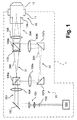
図1〜図3には、それぞれ、本発明の一実施形態による、照明装置を備えた走査顕微鏡のビーム路が簡単化された概略図で示されている。ここで、図1〜図3に示されている実施形態は、複数の共通の素子を含み、以下ではまず図1を参照しながらこれらを説明する。当該説明は他の図にも該当する。 1 to 3 are schematic views showing a simplified beam path of a scanning microscope equipped with an illumination device according to an embodiment of the present invention, respectively. Here, the embodiments shown in FIGS. 1 to 3 include a plurality of common elements, and these will be described below with reference to FIG. 1 first. The explanation also applies to other figures.
図1に示されている走査顕微鏡は、ここでは全体として大幅に概略的な図示となっているが、破線で囲まれて参照番号1を付されており、対物レンズ位置10で、対物レンズ収容部11内に収容された対物レンズ12を含んでいる。種々のタイプの対物レンズ収容部、例えば対物レンズ回転器、リニア対物レンズ交換機構およびこれらに類似のものを設けることができる。対物レンズ12の対物瞳には参照番号109が付されている。
The scanning microscope shown in FIG. 1 is shown here in a largely schematic manner as a whole, but it is surrounded by a broken line and has a reference number 1, and the objective lens is accommodated at the
相応の走査顕微鏡の照明装置には、全体として参照番号20が付されている。オルソスコピックビーム路は参照番号200で、コノスコピックビーム路は参照番号201(破線)で示されている。ここで、オルソスコピックビーム路200およびコノスコピックビーム路201は、照明装置20またはその内部に実現されているビーム路の所定の共通の区間を共通に延在し、これに対して第1の光学チャネル21内および第2の光学チャネル22内を相互に別個に延在する。第1のチャネル21および第2のチャネル22は、ここでは、それぞれ偏光依存性の第1のビームスプリッタ105aと偏光依存性の第2のビームスプリッタ105bとの間に形成されている。
The illumination device of the corresponding scanning microscope is numbered 20 as a whole. The orthoscopic beam path is indicated by
オルソスコピックビーム路200とコノスコピックビーム路201とを切り替えるために、光源100によって形成された照明光ビームの、例えば相互に直交する2つの主偏光方向が用いられる。このために、偏光照明光を相応に予め形成する相応の光源100を用いることができる。光源100は、例えば、レーザー光源、または偏光を行う光ファイバもしくは適切な偏光素子、または未偏光の光用の、相応の偏光素子を含む光源であってよい。
In order to switch between the
相応の光源100によって形成された照明光ビームの主偏光方向の切り替えは、ここでは大幅に簡単化されて参照番号102で示されている種々の装置によって実現することができる。例えば、相応の装置102は機械的に高速に切り替え可能な遅延素子(例えば半波長板)を含むことができ、この遅延素子は好ましくは、ビーム路または照明光ビームが小さなビーム径および一定のビーム位置を有する箇所に配置されている。例えば、相応の遅延素子または相応の装置102は、ファイバコリメータとここでは簡単化されて参照番号101で示されているビーム拡大装置との間に配置することができる。
The switching of the principal polarization direction of the illumination light beam formed by the corresponding
相応の装置102によって主偏光方向を切り替える別の手段として、例えば、従来技術から基本的に公知の音響光学素子、電気光学素子または液晶素子が挙げられる。
As another means for switching the main polarization direction by the
図1に示されている本発明の実施形態では、光源100、装置102、ビーム拡大装置101およびスキャン装置103から形成される光源区間が、つねに、第1の主偏光方向の光または第2の主偏光方向の光のいずれかを供給している。これとは異なる実施形態は例えば図3を参照して説明する。
In the embodiment of the present invention shown in FIG. 1, the light source section formed by the
スキャン装置または走査ユニット103は、それ自体公知の形式で構成されており、例えば傾動可能なミラー、回動可能なプリズムおよび/または同様に基本的に従来技術から公知の音響光学手段を含む。したがって、全体として、光源区間100〜103により、ここでは参照番号203で示されている照明光ビームが形成され、この照明光ビームは、選択的に第1の主偏光方向または第2の主偏光方向を有し、図示の例ではコリメート形態で走査ユニット103から放射される。
The scanning apparatus or
続いて、照明光ビーム203は、1つもしくは複数のレンズから成る第1の光学素子104を通過し、この第1の光学素子104によってフォーカシングされる。第1の主偏光方向または第2の主偏光方向を有する照明光ビーム203は、フォーカシングされてまたは集束されて偏光依存性の第1のビームスプリッタ105aへ入射する。偏光依存性の第1のビームスプリッタ105aの当該境界層では、第2の主偏光方向の光が、ここでは破線のコノスコピックビーム路201の形態で示されているように反射され、これに対して第1の主偏光方向の光は偏向されずに境界層を通過する。
Subsequently, the
このようにして、偏向依存性の第1のビームスプリッタ105aは、第1の主偏光方向を有する光を第1の光学チャネル21へガイドし、第2の主偏光方向を有する光を第2の光学チャネル22へガイドする。第1のチャネル21または第2のチャネル22のそれぞれの焦点を超えた先では、第1の偏光状態の光または第2の偏光状態の光がそれぞれ発散して走行する。図示の例では、第1の主偏光方向を有する光が、ここではオルソスコピックビーム路200で示されているように第1のチャネル21へ入射し、この第1のチャネルから発散して出射し、偏光依存性の第2のビームスプリッタ105bへ入射する。この場合、シャッタ110により、偏光依存性の第2のビームスプリッタへのエラー光の入射を防止することができる。
In this way, the deflection-dependent
図1に示されている実施形態では、第1のチャネル21に、別の光学素子は設けられていない。これに対して、第2の光学チャネル22には、別の光学素子106a,106bが設けられている。第2のチャネル22内を走行する、第2の偏光状態を有する光は、さらに偏向素子107a,107bを介して偏向される。光学素子106a,106bにより、第2の主偏光方向を有する光は第2のチャネル22においてコリメートされ、コリメート形態で偏光依存性の第2のビームスプリッタ105bへ入射する。
In the embodiment shown in FIG. 1, another optical element is not provided in the
相応に、第1の主偏光方向を有する光は、第1のチャネル21から、偏光依存性の第2のビームスプリッタ105bを通過した後、発散してそこから出射し、これに対して、第2の主偏光方向を有する光は、第2のチャネル22から、第2のチャネルおよび偏光依存性の第2のビームスプリッタ105bを通過した後、コリメートされてそこから出射する。第2の光学素子108、例えばチューブレンズを用いて、第2の光学チャネルからの第2の主偏光方向を有するコリメート光をフォーカシングでき、これに対して、第1の光学チャネルからの第1の主偏光方向を有する光はコリメート可能である。第2の光学素子108は、既述の光学素子106a,106bとともにベルトランレンズを形成する。第1の光学チャネル21および第2の光学チャネル22の構成ならびに上述したレンズの配置により、第1の主偏光方向を有する光は、対物レンズ12の後側対物瞳109内へコリメート形態で入射可能となり、これに対して第2の主偏光方向を有する光は、対物レンズ12の後側対物瞳109内へフォーカシング可能となる。第2の光学素子108は、第1の光学素子104とともに、スキャン装置103によって生じる1つもしくは複数の実偏向点または虚偏向点を対物瞳109内またはその近傍へ結像するガリレオ望遠鏡を形成する。
Correspondingly, the light having the first primary polarization direction passes through the polarization-dependent
対物レンズ12の先に配置された試料の蛍光の検出は、従来の広視野蛍光顕微鏡によって行うことができる。ここで説明している実施形態の照明装置20は、こうした広視野蛍光顕微鏡では、蛍光照明ビーム路の適切な箇所に挿入され、取り外し可能に構成することができる。特に有利には、光学素子106a,106b,108から形成されるベルトランレンズ装置は可変のフォーカシング部を有し、この可変のフォーカシング部により、例えば種々の対物レンズまたは1つのフォーカシング回転器が利用される場合、対物瞳109の種々の機械的位置でのフォーカシングが可能である。特に有利には、上述したように例えばチューブレンズの形態で構成可能な第2の光学素子108を、相応にフォーカシング可能なベルトランレンズ装置において一定に支持でき、これにより照明装置20の交換時にもこれを取り外す必要なく、さらに素子104,108から形成されるガリレオ望遠鏡の無限焦点も保持される。
The fluorescence of the sample placed in front of the
図2に示されている走査顕微鏡2の実施形態は、シャッタ110が存在しない点で、図1に示されている実施形態と異なる。当該シャッタにより、上述したように、図1に示されている走査顕微鏡1の実施形態では、理想的でない偏光に起因するエラー光の除去が可能である。ただし、光源区間100〜103により既に充分な偏光の光が形成されることから当該除去が必要ない場合、当該付加的なシャッタ110を省略することもでき、これにより顕微鏡2の機械的構成を簡単化することができる。
The embodiment of the
図3に示されている走査顕微鏡3の実施形態では、図1,図2に示されている実施形態で設けられていた可変の遅延素子または相応の装置102が設けられていない。これに代えて、第1のチャネル21および第2のチャネル22の双方に高速のシャッタ素子110,111が設けられている。光源区間100〜103または光源100は、この場合、例えば固定の偏光状態を有する照明光を形成し、この照明光は、2つの直交する主偏光方向の光の線形結合である。したがって、偏光依存性の第1のビームスプリッタ105aにより、2つのチャネル21,22の照明光が偏向される。2つのチャネル21,22のシャッタ110,111を交互に用いることにより、選択的にビーム路をブロックし、このようにしてそれぞれ唯一のチャネルを通して光を対物レンズ12へ導波することができる。もちろん、シャッタ110,111を相応に駆動することにより、2つのチャネル21,22の双方を通る光または双方とも通らない光を形成することもできる。
In the embodiment of the scanning microscope 3 shown in FIG. 3, the variable delay element or the
1,2,3 走査顕微鏡
10 対物レンズ位置
11 対物レンズ収容部
12 対物レンズ
20 照明装置
21 第1の光学チャネル
22 第2の光学チャネル
100 光源
101 ビーム拡大装置
102 遅延素子
103 走査ユニット
104 第1の光学素子
105a,105b 偏光依存性のビームスプリッタ
106a,106b 別の光学素子
107a,107b ビーム偏向素子
108 第2の光学素子
109 対物レンズの入射瞳
110,111 シャッタ
200 オルソスコピックビーム路
201 コノスコピックビーム路
203 第1の照明光ビーム
204 第2の照明光ビーム
1, 2, 3
Claims (16)
前記光学走査顕微鏡(1,2,3)は、光源(100)から出発する光源区間(100〜103)、偏光依存性の第1のビームスプリッタ(105a)および偏光依存性の第2のビームスプリッタ(105b)、ならびに、前記偏光依存性の第1のビームスプリッタ(105a)と前記偏光依存性の第2のビームスプリッタ(105b)との間の第1の光学チャネル(21)および第2の光学チャネル(22)を有する照明装置(20)を備え、
・前記光源区間(100〜103)は、第1の時間範囲では主としてもしくは専ら第1の主偏光方向の光を含み、第2の時間範囲では主としてもしくは専ら第2の主偏光方向の光を含む第1の照明光ビーム(203)を放射するように構成されており、
・前記第1のビームスプリッタ(105a)は、前記第1の主偏光方向の光の少なくとも大部分を前記第1の光学チャネル(21)へガイドし、前記第2の主偏光方向の光の少なくとも大部分を前記第2の光学チャネル(22)へガイドするように構成されており、
・前記第2のビームスプリッタ(105b)は、前記第1の光学チャネル(21)からの前記第1の主偏光方向の光と、前記第2の光学チャネル(22)からの前記第2の主偏光方向の光と、から第2の照明光ビーム(204)を形成するように構成されており、
・各前記光学チャネル(21,22)は、前記第1の光学チャネル(21)からの前記第1の主偏光方向の光と、前記第2の光学チャネル(22)からの前記第2の主偏光方向の光と、をそれぞれ異なる集束角度で放射するように構成されている、
光学走査顕微鏡(1,2,3)。 Optical scanning microscope (1, 2, 3)
The optical scanning microscopes (1, 2, 3) include a light source section (100 to 103) starting from the light source (100), a polarization-dependent first beam splitter (105a), and a polarization-dependent second beam splitter. (105b), and the first optical channel (21) and second optics between the polarization-dependent first beam splitter (105a) and the polarization-dependent second beam splitter (105b). A lighting device (20) having a channel (22)
The light source section (100 to 103) mainly or exclusively includes light in the first main polarization direction in the first time range, and mainly or exclusively includes light in the second main polarization direction in the second time range. It is configured to radiate a first illumination light beam (203).
The first beam splitter (105a) guides at least most of the light in the first main polarization direction to the first optical channel (21), and at least the light in the second main polarization direction. It is configured to guide most of it to the second optical channel (22).
The second beam splitter (105b) includes light from the first optical channel (21) in the first main polarization direction and the second main from the second optical channel (22). It is configured to form a second illumination beam (204) from the light in the polarization direction.
Each of the optical channels (21, 22) has the light in the first main polarization direction from the first optical channel (21) and the second main from the second optical channel (22). It is configured to emit light in the polarization direction at different focusing angles.
Optical scanning microscope (1, 2, 3).
請求項1記載の光学走査顕微鏡(1,2,3)。 The light source section (100 to 103) is configured to collimate and radiate the first illumination light beam (203).
The optical scanning microscope according to claim 1 (1, 2, 3).
請求項2記載の光学走査顕微鏡(1,2,3)。 A first optical element (104) is arranged upstream of the first beam splitter (105a), and the first optical element (104) focuses the first illumination light beam (203). And it is configured to be focused and incident on the first beam splitter (105a).
The optical scanning microscope according to claim 2 (1, 2, 3).
前記第2の光学チャネル(22)は、光の少なくとも大部分をコリメートして前記第2のビームスプリッタ(105b)へ入射させるように構成されている、
請求項3記載の光学走査顕微鏡(1,2,3)。 The first optical channel (21) is configured to diverge at least most of the light and enter into the second beam splitter (105b).
The second optical channel (22) is configured to collimate at least most of the light and enter into the second beam splitter (105b).
The optical scanning microscope according to claim 3 (1, 2, 3).
請求項4記載の光学走査顕微鏡(1,2,3)。 A second optical element (108) is arranged downstream of the second beam splitter (105b), and the second optical element (108) is diverged by the second beam splitter (105b). It is configured to collimate the emitted light and focus the emitted light collimated by the second beam splitter (105b).
The optical scanning microscope according to claim 4 (1, 2, 3).
前記第2の光学素子(108)は、前記第2のビームスプリッタ(105b)からコリメートされて出射される光を前記後側対物瞳(109)の平面へフォーカシングするように構成されている、
請求項5記載の光学走査顕微鏡(1,2,3)。 An objective lens (12) that can be mounted in the objective lens accommodating portion (11), can be positioned at the objective lens position (10), and includes the rear objective pupil (109) is provided.
The second optical element (108) is configured to focus the light collimated and emitted from the second beam splitter (105b) onto the plane of the rear objective pupil (109).
The optical scanning microscope according to claim 5 (1, 2, 3).
請求項1から6までのいずれか1項記載の光学走査顕微鏡(1,2,3)。 At least a part of the belt run lens apparatus (106a, 106b) is prepared in the second optical channel (22).
The optical scanning microscope (1, 2, 3) according to any one of claims 1 to 6.
請求項1から7までのいずれか1項記載の光学走査顕微鏡(1,2,3)。 An orthoscopic beam path (200) is formed in the lighting device (20) by the light in the first main polarization direction, and a conoscopic beam path (201) is formed by the light in the second main polarization direction. NS,
The optical scanning microscope (1, 2, 3) according to any one of claims 1 to 7.
請求項1記載の光学走査顕微鏡(1,2,3)。 The first illumination light beam (203) including the light in the first main polarization direction in the first time range and the light in the second main polarization direction in the second time range is emitted. A switchable delay element (102) is provided for this purpose.
The optical scanning microscope according to claim 1 (1, 2, 3).
請求項1から9までのいずれか1項記載の光学走査顕微鏡(1,2,3)。 The lighting device (20) includes a scanning unit (103).
The optical scanning microscope (1, 2, 3) according to any one of claims 1 to 9.
請求項1から10までのいずれか1項記載の光学走査顕微鏡(1,2,3)。 A plurality of optical elements (104, 108) are prepared along the first optical channel (21), and the plurality of optical elements (104, 108) may be one or a plurality of scanning devices (103). It is configured and arranged to form a Galilean telescope that images real or imaginary deflection points into or near the objective pupil (109).
The optical scanning microscope (1, 2, 3) according to any one of claims 1 to 10.
請求項1から11までのいずれか1項記載の光学走査顕微鏡(1,2,3)。 An optical shutter is arranged in the first optical channel (21) and / or in the second optical channel (22).
The optical scanning microscope (1, 2, 3) according to any one of claims 1 to 11.
請求項1から12までのいずれか1項記載の光学走査顕微鏡(1,2,3)。 The first beam splitter and the second beam splitter (105a, 105b) and the first optical channel (21) and the second optical channel (22) are the optical scanning microscopes (1, 2, 3). ) Is placed on the insertable member,
The optical scanning microscope (1, 2, 3) according to any one of claims 1 to 12.
請求項1から13までのいずれか1項記載の光学走査顕微鏡(1,2,3)。 Including means for adapting as a partial module to a wide-field microscope,
The optical scanning microscope (1, 2, 3) according to any one of claims 1 to 13.
前記光学走査顕微鏡(1,2,3)は、光源区間(100〜103)、偏光依存性の第1のビームスプリッタ(105a)および偏光依存性の第2のビームスプリッタ(105b)、ならびに、前記第1のビームスプリッタ(105a)と前記第2のビームスプリッタ(105b)との間の第1の光学チャネル(21)および第2の光学チャネル(22)を有する照明装置(20)を備え、
・前記光源区間(100〜103)を用いて、第1の時間範囲では主としてもしくは専ら第1の主偏光方向の光を含み、第2の時間範囲では主としてもしくは専ら第2の主偏光方向の光を含む第1の照明光ビーム(203)を放射し、
・前記第1のビームスプリッタ(105a)を用いて、前記第1の主偏光方向の光の少なくとも大部分を前記第1の光学チャネル(21)へガイドし、前記第2の主偏光方向の光の少なくとも大部分を前記第2の光学チャネル(22)へガイドし、
・前記第2のビームスプリッタ(105b)を用いて、前記第1の光学チャネル(21)からの前記第1の主偏光方向の光と、前記第2の光学チャネル(22)からの前記第2の主偏光方向の光と、から第2の照明光ビーム(204)を形成し、
・前記第1の光学チャネル(21)を用いた第1の偏光状態の光と、前記第2の光学チャネル(22)を用いた第2の偏光状態の光と、をそれぞれ異なる集束角度で放射する、
方法。 A method of inspecting a sample using an optical scanning microscope (1, 2, 3).
The optical scanning microscopes (1, 2, 3) include a light source section (100 to 103), a polarization-dependent first beam splitter (105a) and a polarization-dependent second beam splitter (105b), and the above. A lighting device (20) having a first optical channel (21) and a second optical channel (22) between the first beam splitter (105a) and the second beam splitter (105b).
-Using the light source section ( 100 to 103), the first time range mainly or exclusively includes the light in the first main polarization direction , and the second time range mainly or exclusively the light in the second main polarization direction. A first illumination light beam (203) containing
Using the first beam splitter (105a), at least most of the light in the first main polarization direction is guided to the first optical channel (21), and the light in the second main polarization direction is guided. At least most of the above is guided to the second optical channel (22).
Using the second beam splitter (105b), the light in the first main polarization direction from the first optical channel (21) and the second from the second optical channel (22). Forming a second illumination light beam (204) from the light in the primary polarization direction of
-Light in a first polarized state using the first optical channel (21) and light in a second polarized state using the second optical channel (22) are emitted at different focusing angles. do,
Method.
請求項15記載の方法。 The scanning microscope (1, 2, 3) according to any one of claims 1 to 14 is used.
15. The method of claim 15.
Applications Claiming Priority (3)
| Application Number | Priority Date | Filing Date | Title |
|---|---|---|---|
| DE102016108987.7 | 2016-05-13 | ||
| DE102016108987.7A DE102016108987A1 (en) | 2016-05-13 | 2016-05-13 | Optical scanning microscope and examination method |
| PCT/EP2017/061470 WO2017194742A1 (en) | 2016-05-13 | 2017-05-12 | Optical scanning microscope and examination method |
Publications (3)
| Publication Number | Publication Date |
|---|---|
| JP2019517027A JP2019517027A (en) | 2019-06-20 |
| JP2019517027A5 JP2019517027A5 (en) | 2020-03-12 |
| JP6945557B2 true JP6945557B2 (en) | 2021-10-06 |
Family
ID=58709942
Family Applications (1)
| Application Number | Title | Priority Date | Filing Date |
|---|---|---|---|
| JP2018559780A Active JP6945557B2 (en) | 2016-05-13 | 2017-05-12 | Optical scanning microscope and inspection method |
Country Status (5)
| Country | Link |
|---|---|
| US (1) | US11630292B2 (en) |
| EP (1) | EP3455663A1 (en) |
| JP (1) | JP6945557B2 (en) |
| DE (2) | DE202016008489U1 (en) |
| WO (1) | WO2017194742A1 (en) |
Families Citing this family (3)
| Publication number | Priority date | Publication date | Assignee | Title |
|---|---|---|---|---|
| DE102019135521A1 (en) * | 2019-12-20 | 2021-06-24 | Carl Zeiss Microscopy Gmbh | Measuring arrangement, light microscope and measuring method for imaging depth measurement |
| US11921273B2 (en) | 2020-10-30 | 2024-03-05 | Electronics And Telecommunications Research Institute | Two-photon excited fluorescence microscope for diagnosis of Alzheimer's disease (AD) and mild cognitive impairment (MCI), and pulse compressor including therein |
| KR102572214B1 (en) * | 2020-10-30 | 2023-08-30 | 한국전자통신연구원 | two-photon excited fluorescence microscopy for diagnosis of dementia and Mild Cognitive Impairment (MCI), and pulse compressor included therein |
Family Cites Families (19)
| Publication number | Priority date | Publication date | Assignee | Title |
|---|---|---|---|---|
| US6091523A (en) * | 1989-02-07 | 2000-07-18 | Northrop Grumman Corporation | Multi-channel receiver |
| JP3942906B2 (en) * | 2002-02-01 | 2007-07-11 | 株式会社ニデック | Laser therapy device |
| JP4414722B2 (en) | 2003-10-15 | 2010-02-10 | オリンパス株式会社 | Laser microscope |
| DE102005020545A1 (en) * | 2005-05-03 | 2006-11-09 | Carl Zeiss Jena Gmbh | Device for controlling light radiation |
| DE102005037818A1 (en) | 2005-08-08 | 2007-02-15 | Leica Microsystems Cms Gmbh | microscope |
| DE102006028530A1 (en) | 2005-11-11 | 2007-05-16 | Till I D Gmbh | Microscope having optional investigation of a sample has two light beams on different directions and a beam deflector operated by a drive to couple a beam to the objective |
| DE102006033306A1 (en) | 2006-07-17 | 2008-01-31 | Leica Microsystems Cms Gmbh | Tirf microscope |
| US7706069B2 (en) * | 2007-05-14 | 2010-04-27 | Coherent, Inc. | Attenuator for high-power unpolarized laser beams |
| CN102597845B (en) * | 2009-11-02 | 2016-06-29 | 奥林巴斯株式会社 | Beam splitter apparatus, light supply apparatus and scanning observation device |
| JP5551477B2 (en) * | 2010-03-15 | 2014-07-16 | オリンパス株式会社 | Light source device and laser scanning microscope device |
| US9411144B2 (en) * | 2011-01-12 | 2016-08-09 | Ge Healthcare Bio-Sciences Corp. | Systems for fluorescence illumination using superimposed polarization states |
| WO2012099151A1 (en) * | 2011-01-18 | 2012-07-26 | オリンパス株式会社 | Optical scanning device and scanning inspection device |
| EP2776784B1 (en) * | 2011-11-08 | 2015-10-07 | Universite Laval | Method and system for improving resolution in laser imaging microscopy |
| DE102012010207B4 (en) * | 2012-05-15 | 2024-02-29 | Carl Zeiss Microscopy Gmbh | Microscope and microscopy methods |
| JP2014164097A (en) * | 2013-02-25 | 2014-09-08 | Olympus Corp | Beam splitter device, scanning observation device, laser scanning microscope and laser scanning endoscope |
| US9110294B2 (en) * | 2013-03-15 | 2015-08-18 | Christie Digital Systems Usa, Inc. | Imaging with shaped highlight beam |
| DE102013222562B4 (en) | 2013-11-06 | 2023-01-26 | Leica Microsystems Cms Gmbh | Microscope and method and use of a microscope for evanescent illumination and point grid illumination |
| US9606069B2 (en) * | 2014-06-25 | 2017-03-28 | Kla-Tencor Corporation | Method, apparatus and system for generating multiple spatially separated inspection regions on a substrate |
| GB201508376D0 (en) | 2015-05-15 | 2015-07-01 | Univ St Andrews | Light sheet imaging |
-
2016
- 2016-05-13 DE DE202016008489.6U patent/DE202016008489U1/en active Active
- 2016-05-13 DE DE102016108987.7A patent/DE102016108987A1/en not_active Withdrawn
-
2017
- 2017-05-12 WO PCT/EP2017/061470 patent/WO2017194742A1/en unknown
- 2017-05-12 EP EP17723981.1A patent/EP3455663A1/en active Pending
- 2017-05-12 US US16/300,966 patent/US11630292B2/en active Active
- 2017-05-12 JP JP2018559780A patent/JP6945557B2/en active Active
Also Published As
| Publication number | Publication date |
|---|---|
| JP2019517027A (en) | 2019-06-20 |
| DE202016008489U1 (en) | 2018-02-22 |
| EP3455663A1 (en) | 2019-03-20 |
| WO2017194742A1 (en) | 2017-11-16 |
| US11630292B2 (en) | 2023-04-18 |
| US20200319445A1 (en) | 2020-10-08 |
| DE102016108987A1 (en) | 2017-11-16 |
Similar Documents
| Publication | Publication Date | Title |
|---|---|---|
| US7782529B2 (en) | Scanning microscope and method for examining a sample by using scanning microscopy | |
| JP4671463B2 (en) | Illumination optical system and microscope equipped with illumination optical system | |
| US8848268B2 (en) | Microscope with light sheet illumination | |
| US20200081237A1 (en) | Light-Scanning Microscope with Simplified Optical System, More Particularly with Variable Pupil Position | |
| JP5941634B2 (en) | Microscope including micro and macro objectives | |
| US7405874B2 (en) | Microscope for epi fluorescence and total internal reflection microscopy | |
| JP6282654B2 (en) | Optical system configuration and optical microscope | |
| US20150192767A1 (en) | Multiplane optical microscope | |
| US20110102888A1 (en) | Microscope | |
| JP6945557B2 (en) | Optical scanning microscope and inspection method | |
| JP2007334319A (en) | Illuminating device | |
| US20060250689A1 (en) | Objective for evanescent illumination and microscope | |
| JPH11119106A (en) | Laser scanning microscope | |
| US20060245047A1 (en) | Illumination module for evanescent illumination and microscope | |
| JP7025530B2 (en) | Dynamic focus zoom system for wide-area confocal and multiphoton microscopy | |
| JP6534662B2 (en) | Microscope for evanescent illumination and point raster scan illumination | |
| JPH08136817A (en) | Slit light microscope | |
| US9069167B2 (en) | Illumination apparatus for microscope and microscope using the same | |
| JP2019514060A (en) | Method and microscope for inspecting a sample | |
| JP2008276230A (en) | Optical component for stereomicroscope | |
| JP2004318181A (en) | Inverted microscope | |
| JP2011118069A (en) | Microscope illumination device and microscope | |
| JP2022162999A (en) | Microscope system with oblique illumination | |
| JP4532852B2 (en) | Polarization microscope and polarization observation intermediate tube | |
| JP5443939B2 (en) | Laser illumination device and laser microscope provided with the same |
Legal Events
| Date | Code | Title | Description |
|---|---|---|---|
| A521 | Request for written amendment filed |
Free format text: JAPANESE INTERMEDIATE CODE: A821 Effective date: 20181112 |
|
| A521 | Request for written amendment filed |
Free format text: JAPANESE INTERMEDIATE CODE: A523 Effective date: 20200129 |
|
| A621 | Written request for application examination |
Free format text: JAPANESE INTERMEDIATE CODE: A621 Effective date: 20200129 |
|
| A977 | Report on retrieval |
Free format text: JAPANESE INTERMEDIATE CODE: A971007 Effective date: 20201221 |
|
| A131 | Notification of reasons for refusal |
Free format text: JAPANESE INTERMEDIATE CODE: A131 Effective date: 20210106 |
|
| TRDD | Decision of grant or rejection written | ||
| A01 | Written decision to grant a patent or to grant a registration (utility model) |
Free format text: JAPANESE INTERMEDIATE CODE: A01 Effective date: 20210823 |
|
| A61 | First payment of annual fees (during grant procedure) |
Free format text: JAPANESE INTERMEDIATE CODE: A61 Effective date: 20210914 |
|
| R150 | Certificate of patent or registration of utility model |
Ref document number: 6945557 Country of ref document: JP Free format text: JAPANESE INTERMEDIATE CODE: R150 |