KR20200048000A - Method for press molding of compound material - Google Patents
Method for press molding of compound material Download PDFInfo
- Publication number
- KR20200048000A KR20200048000A KR1020180129584A KR20180129584A KR20200048000A KR 20200048000 A KR20200048000 A KR 20200048000A KR 1020180129584 A KR1020180129584 A KR 1020180129584A KR 20180129584 A KR20180129584 A KR 20180129584A KR 20200048000 A KR20200048000 A KR 20200048000A
- Authority
- KR
- South Korea
- Prior art keywords
- metal member
- composite material
- lower metal
- coating film
- adhered
- Prior art date
Links
- 238000000034 method Methods 0.000 title claims abstract description 38
- 238000000465 moulding Methods 0.000 title abstract description 6
- 239000000463 material Substances 0.000 title description 4
- 150000001875 compounds Chemical class 0.000 title 1
- 229910052751 metal Inorganic materials 0.000 claims abstract description 114
- 239000002184 metal Substances 0.000 claims abstract description 114
- 239000002131 composite material Substances 0.000 claims abstract description 73
- 239000011347 resin Substances 0.000 claims abstract description 41
- 229920005989 resin Polymers 0.000 claims abstract description 41
- 239000011248 coating agent Substances 0.000 claims abstract description 38
- 238000000576 coating method Methods 0.000 claims abstract description 38
- 239000012943 hotmelt Substances 0.000 claims abstract description 30
- 238000009957 hemming Methods 0.000 claims abstract description 25
- 238000005452 bending Methods 0.000 claims abstract description 15
- 238000004519 manufacturing process Methods 0.000 claims abstract description 11
- 238000005520 cutting process Methods 0.000 claims abstract description 8
- 238000003825 pressing Methods 0.000 claims 4
- 239000010935 stainless steel Substances 0.000 description 4
- 229910001220 stainless steel Inorganic materials 0.000 description 4
- 238000005538 encapsulation Methods 0.000 description 3
- 239000012044 organic layer Substances 0.000 description 3
- QVGXLLKOCUKJST-UHFFFAOYSA-N atomic oxygen Chemical compound [O] QVGXLLKOCUKJST-UHFFFAOYSA-N 0.000 description 2
- 229910052760 oxygen Inorganic materials 0.000 description 2
- 239000001301 oxygen Substances 0.000 description 2
- 238000003672 processing method Methods 0.000 description 2
- 229910052782 aluminium Inorganic materials 0.000 description 1
- 239000010960 cold rolled steel Substances 0.000 description 1
- 230000000694 effects Effects 0.000 description 1
- 239000011521 glass Substances 0.000 description 1
- 230000005283 ground state Effects 0.000 description 1
- 238000012986 modification Methods 0.000 description 1
- 230000004048 modification Effects 0.000 description 1
- 230000035515 penetration Effects 0.000 description 1
Images


Classifications
-
- B—PERFORMING OPERATIONS; TRANSPORTING
- B21—MECHANICAL METAL-WORKING WITHOUT ESSENTIALLY REMOVING MATERIAL; PUNCHING METAL
- B21D—WORKING OR PROCESSING OF SHEET METAL OR METAL TUBES, RODS OR PROFILES WITHOUT ESSENTIALLY REMOVING MATERIAL; PUNCHING METAL
- B21D39/00—Application of procedures in order to connect objects or parts, e.g. coating with sheet metal otherwise than by plating; Tube expanders
- B21D39/02—Application of procedures in order to connect objects or parts, e.g. coating with sheet metal otherwise than by plating; Tube expanders of sheet metal by folding, e.g. connecting edges of a sheet to form a cylinder
- B21D39/021—Application of procedures in order to connect objects or parts, e.g. coating with sheet metal otherwise than by plating; Tube expanders of sheet metal by folding, e.g. connecting edges of a sheet to form a cylinder for panels, e.g. vehicle doors
-
- H—ELECTRICITY
- H10—SEMICONDUCTOR DEVICES; ELECTRIC SOLID-STATE DEVICES NOT OTHERWISE PROVIDED FOR
- H10K—ORGANIC ELECTRIC SOLID-STATE DEVICES
- H10K50/00—Organic light-emitting devices
- H10K50/80—Constructional details
- H10K50/84—Passivation; Containers; Encapsulations
-
- B—PERFORMING OPERATIONS; TRANSPORTING
- B29—WORKING OF PLASTICS; WORKING OF SUBSTANCES IN A PLASTIC STATE IN GENERAL
- B29C—SHAPING OR JOINING OF PLASTICS; SHAPING OF MATERIAL IN A PLASTIC STATE, NOT OTHERWISE PROVIDED FOR; AFTER-TREATMENT OF THE SHAPED PRODUCTS, e.g. REPAIRING
- B29C65/00—Joining or sealing of preformed parts, e.g. welding of plastics materials; Apparatus therefor
- B29C65/48—Joining or sealing of preformed parts, e.g. welding of plastics materials; Apparatus therefor using adhesives, i.e. using supplementary joining material; solvent bonding
- B29C65/4805—Joining or sealing of preformed parts, e.g. welding of plastics materials; Apparatus therefor using adhesives, i.e. using supplementary joining material; solvent bonding characterised by the type of adhesives
- B29C65/481—Non-reactive adhesives, e.g. physically hardening adhesives
- B29C65/4815—Hot melt adhesives, e.g. thermoplastic adhesives
-
- B—PERFORMING OPERATIONS; TRANSPORTING
- B29—WORKING OF PLASTICS; WORKING OF SUBSTANCES IN A PLASTIC STATE IN GENERAL
- B29C—SHAPING OR JOINING OF PLASTICS; SHAPING OF MATERIAL IN A PLASTIC STATE, NOT OTHERWISE PROVIDED FOR; AFTER-TREATMENT OF THE SHAPED PRODUCTS, e.g. REPAIRING
- B29C66/00—General aspects of processes or apparatus for joining preformed parts
- B29C66/01—General aspects dealing with the joint area or with the area to be joined
- B29C66/03—After-treatments in the joint area
- B29C66/032—Mechanical after-treatments
- B29C66/0322—Post-pressing without reshaping, i.e. keeping the joint under pressure after joining
-
- B—PERFORMING OPERATIONS; TRANSPORTING
- B29—WORKING OF PLASTICS; WORKING OF SUBSTANCES IN A PLASTIC STATE IN GENERAL
- B29C—SHAPING OR JOINING OF PLASTICS; SHAPING OF MATERIAL IN A PLASTIC STATE, NOT OTHERWISE PROVIDED FOR; AFTER-TREATMENT OF THE SHAPED PRODUCTS, e.g. REPAIRING
- B29C66/00—General aspects of processes or apparatus for joining preformed parts
- B29C66/01—General aspects dealing with the joint area or with the area to be joined
- B29C66/03—After-treatments in the joint area
- B29C66/032—Mechanical after-treatments
- B29C66/0324—Reforming or reshaping the joint, e.g. folding over
-
- B—PERFORMING OPERATIONS; TRANSPORTING
- B29—WORKING OF PLASTICS; WORKING OF SUBSTANCES IN A PLASTIC STATE IN GENERAL
- B29C—SHAPING OR JOINING OF PLASTICS; SHAPING OF MATERIAL IN A PLASTIC STATE, NOT OTHERWISE PROVIDED FOR; AFTER-TREATMENT OF THE SHAPED PRODUCTS, e.g. REPAIRING
- B29C66/00—General aspects of processes or apparatus for joining preformed parts
- B29C66/01—General aspects dealing with the joint area or with the area to be joined
- B29C66/03—After-treatments in the joint area
- B29C66/032—Mechanical after-treatments
- B29C66/0326—Cutting, e.g. by using waterjets, or perforating
-
- B—PERFORMING OPERATIONS; TRANSPORTING
- B29—WORKING OF PLASTICS; WORKING OF SUBSTANCES IN A PLASTIC STATE IN GENERAL
- B29C—SHAPING OR JOINING OF PLASTICS; SHAPING OF MATERIAL IN A PLASTIC STATE, NOT OTHERWISE PROVIDED FOR; AFTER-TREATMENT OF THE SHAPED PRODUCTS, e.g. REPAIRING
- B29C66/00—General aspects of processes or apparatus for joining preformed parts
- B29C66/01—General aspects dealing with the joint area or with the area to be joined
- B29C66/05—Particular design of joint configurations
- B29C66/10—Particular design of joint configurations particular design of the joint cross-sections
- B29C66/11—Joint cross-sections comprising a single joint-segment, i.e. one of the parts to be joined comprising a single joint-segment in the joint cross-section
- B29C66/112—Single lapped joints
- B29C66/1122—Single lap to lap joints, i.e. overlap joints
-
- B—PERFORMING OPERATIONS; TRANSPORTING
- B29—WORKING OF PLASTICS; WORKING OF SUBSTANCES IN A PLASTIC STATE IN GENERAL
- B29C—SHAPING OR JOINING OF PLASTICS; SHAPING OF MATERIAL IN A PLASTIC STATE, NOT OTHERWISE PROVIDED FOR; AFTER-TREATMENT OF THE SHAPED PRODUCTS, e.g. REPAIRING
- B29C66/00—General aspects of processes or apparatus for joining preformed parts
- B29C66/70—General aspects of processes or apparatus for joining preformed parts characterised by the composition, physical properties or the structure of the material of the parts to be joined; Joining with non-plastics material
- B29C66/74—Joining plastics material to non-plastics material
- B29C66/742—Joining plastics material to non-plastics material to metals or their alloys
-
- B—PERFORMING OPERATIONS; TRANSPORTING
- B32—LAYERED PRODUCTS
- B32B—LAYERED PRODUCTS, i.e. PRODUCTS BUILT-UP OF STRATA OF FLAT OR NON-FLAT, e.g. CELLULAR OR HONEYCOMB, FORM
- B32B15/00—Layered products comprising a layer of metal
- B32B15/04—Layered products comprising a layer of metal comprising metal as the main or only constituent of a layer, which is next to another layer of the same or of a different material
- B32B15/08—Layered products comprising a layer of metal comprising metal as the main or only constituent of a layer, which is next to another layer of the same or of a different material of synthetic resin
-
- B—PERFORMING OPERATIONS; TRANSPORTING
- B32—LAYERED PRODUCTS
- B32B—LAYERED PRODUCTS, i.e. PRODUCTS BUILT-UP OF STRATA OF FLAT OR NON-FLAT, e.g. CELLULAR OR HONEYCOMB, FORM
- B32B15/00—Layered products comprising a layer of metal
- B32B15/18—Layered products comprising a layer of metal comprising iron or steel
-
- B—PERFORMING OPERATIONS; TRANSPORTING
- B32—LAYERED PRODUCTS
- B32B—LAYERED PRODUCTS, i.e. PRODUCTS BUILT-UP OF STRATA OF FLAT OR NON-FLAT, e.g. CELLULAR OR HONEYCOMB, FORM
- B32B15/00—Layered products comprising a layer of metal
- B32B15/20—Layered products comprising a layer of metal comprising aluminium or copper
-
- B—PERFORMING OPERATIONS; TRANSPORTING
- B32—LAYERED PRODUCTS
- B32B—LAYERED PRODUCTS, i.e. PRODUCTS BUILT-UP OF STRATA OF FLAT OR NON-FLAT, e.g. CELLULAR OR HONEYCOMB, FORM
- B32B27/00—Layered products comprising a layer of synthetic resin
- B32B27/06—Layered products comprising a layer of synthetic resin as the main or only constituent of a layer, which is next to another layer of the same or of a different material
- B32B27/08—Layered products comprising a layer of synthetic resin as the main or only constituent of a layer, which is next to another layer of the same or of a different material of synthetic resin
-
- B—PERFORMING OPERATIONS; TRANSPORTING
- B32—LAYERED PRODUCTS
- B32B—LAYERED PRODUCTS, i.e. PRODUCTS BUILT-UP OF STRATA OF FLAT OR NON-FLAT, e.g. CELLULAR OR HONEYCOMB, FORM
- B32B3/00—Layered products comprising a layer with external or internal discontinuities or unevennesses, or a layer of non-planar shape; Layered products comprising a layer having particular features of form
- B32B3/02—Layered products comprising a layer with external or internal discontinuities or unevennesses, or a layer of non-planar shape; Layered products comprising a layer having particular features of form characterised by features of form at particular places, e.g. in edge regions
- B32B3/04—Layered products comprising a layer with external or internal discontinuities or unevennesses, or a layer of non-planar shape; Layered products comprising a layer having particular features of form characterised by features of form at particular places, e.g. in edge regions characterised by at least one layer folded at the edge, e.g. over another layer ; characterised by at least one layer enveloping or enclosing a material
-
- B—PERFORMING OPERATIONS; TRANSPORTING
- B32—LAYERED PRODUCTS
- B32B—LAYERED PRODUCTS, i.e. PRODUCTS BUILT-UP OF STRATA OF FLAT OR NON-FLAT, e.g. CELLULAR OR HONEYCOMB, FORM
- B32B38/00—Ancillary operations in connection with laminating processes
- B32B38/0004—Cutting, tearing or severing, e.g. bursting; Cutter details
-
- B—PERFORMING OPERATIONS; TRANSPORTING
- B32—LAYERED PRODUCTS
- B32B—LAYERED PRODUCTS, i.e. PRODUCTS BUILT-UP OF STRATA OF FLAT OR NON-FLAT, e.g. CELLULAR OR HONEYCOMB, FORM
- B32B38/00—Ancillary operations in connection with laminating processes
- B32B38/0012—Mechanical treatment, e.g. roughening, deforming, stretching
-
- B—PERFORMING OPERATIONS; TRANSPORTING
- B32—LAYERED PRODUCTS
- B32B—LAYERED PRODUCTS, i.e. PRODUCTS BUILT-UP OF STRATA OF FLAT OR NON-FLAT, e.g. CELLULAR OR HONEYCOMB, FORM
- B32B38/00—Ancillary operations in connection with laminating processes
- B32B38/10—Removing layers, or parts of layers, mechanically or chemically
- B32B38/105—Removing layers, or parts of layers, mechanically or chemically on edges
-
- B—PERFORMING OPERATIONS; TRANSPORTING
- B32—LAYERED PRODUCTS
- B32B—LAYERED PRODUCTS, i.e. PRODUCTS BUILT-UP OF STRATA OF FLAT OR NON-FLAT, e.g. CELLULAR OR HONEYCOMB, FORM
- B32B7/00—Layered products characterised by the relation between layers; Layered products characterised by the relative orientation of features between layers, or by the relative values of a measurable parameter between layers, i.e. products comprising layers having different physical, chemical or physicochemical properties; Layered products characterised by the interconnection of layers
- B32B7/04—Interconnection of layers
- B32B7/06—Interconnection of layers permitting easy separation
-
- B—PERFORMING OPERATIONS; TRANSPORTING
- B32—LAYERED PRODUCTS
- B32B—LAYERED PRODUCTS, i.e. PRODUCTS BUILT-UP OF STRATA OF FLAT OR NON-FLAT, e.g. CELLULAR OR HONEYCOMB, FORM
- B32B7/00—Layered products characterised by the relation between layers; Layered products characterised by the relative orientation of features between layers, or by the relative values of a measurable parameter between layers, i.e. products comprising layers having different physical, chemical or physicochemical properties; Layered products characterised by the interconnection of layers
- B32B7/04—Interconnection of layers
- B32B7/12—Interconnection of layers using interposed adhesives or interposed materials with bonding properties
-
- H—ELECTRICITY
- H10—SEMICONDUCTOR DEVICES; ELECTRIC SOLID-STATE DEVICES NOT OTHERWISE PROVIDED FOR
- H10K—ORGANIC ELECTRIC SOLID-STATE DEVICES
- H10K59/00—Integrated devices, or assemblies of multiple devices, comprising at least one organic light-emitting element covered by group H10K50/00
-
- H—ELECTRICITY
- H10—SEMICONDUCTOR DEVICES; ELECTRIC SOLID-STATE DEVICES NOT OTHERWISE PROVIDED FOR
- H10K—ORGANIC ELECTRIC SOLID-STATE DEVICES
- H10K71/00—Manufacture or treatment specially adapted for the organic devices covered by this subclass
-
- B—PERFORMING OPERATIONS; TRANSPORTING
- B29—WORKING OF PLASTICS; WORKING OF SUBSTANCES IN A PLASTIC STATE IN GENERAL
- B29L—INDEXING SCHEME ASSOCIATED WITH SUBCLASS B29C, RELATING TO PARTICULAR ARTICLES
- B29L2031/00—Other particular articles
- B29L2031/34—Electrical apparatus, e.g. sparking plugs or parts thereof
- B29L2031/3475—Displays, monitors, TV-sets, computer screens
-
- B—PERFORMING OPERATIONS; TRANSPORTING
- B32—LAYERED PRODUCTS
- B32B—LAYERED PRODUCTS, i.e. PRODUCTS BUILT-UP OF STRATA OF FLAT OR NON-FLAT, e.g. CELLULAR OR HONEYCOMB, FORM
- B32B37/00—Methods or apparatus for laminating, e.g. by curing or by ultrasonic bonding
- B32B37/12—Methods or apparatus for laminating, e.g. by curing or by ultrasonic bonding characterised by using adhesives
- B32B37/1207—Heat-activated adhesive
- B32B2037/1215—Hot-melt adhesive
- B32B2037/1223—Hot-melt adhesive film-shaped
-
- B—PERFORMING OPERATIONS; TRANSPORTING
- B32—LAYERED PRODUCTS
- B32B—LAYERED PRODUCTS, i.e. PRODUCTS BUILT-UP OF STRATA OF FLAT OR NON-FLAT, e.g. CELLULAR OR HONEYCOMB, FORM
- B32B37/00—Methods or apparatus for laminating, e.g. by curing or by ultrasonic bonding
- B32B37/14—Methods or apparatus for laminating, e.g. by curing or by ultrasonic bonding characterised by the properties of the layers
- B32B37/26—Methods or apparatus for laminating, e.g. by curing or by ultrasonic bonding characterised by the properties of the layers with at least one layer which influences the bonding during the lamination process, e.g. release layers or pressure equalising layers
- B32B2037/268—Release layers
-
- B—PERFORMING OPERATIONS; TRANSPORTING
- B32—LAYERED PRODUCTS
- B32B—LAYERED PRODUCTS, i.e. PRODUCTS BUILT-UP OF STRATA OF FLAT OR NON-FLAT, e.g. CELLULAR OR HONEYCOMB, FORM
- B32B2250/00—Layers arrangement
- B32B2250/05—5 or more layers
-
- B—PERFORMING OPERATIONS; TRANSPORTING
- B32—LAYERED PRODUCTS
- B32B—LAYERED PRODUCTS, i.e. PRODUCTS BUILT-UP OF STRATA OF FLAT OR NON-FLAT, e.g. CELLULAR OR HONEYCOMB, FORM
- B32B2250/00—Layers arrangement
- B32B2250/40—Symmetrical or sandwich layers, e.g. ABA, ABCBA, ABCCBA
-
- B—PERFORMING OPERATIONS; TRANSPORTING
- B32—LAYERED PRODUCTS
- B32B—LAYERED PRODUCTS, i.e. PRODUCTS BUILT-UP OF STRATA OF FLAT OR NON-FLAT, e.g. CELLULAR OR HONEYCOMB, FORM
- B32B2255/00—Coating on the layer surface
- B32B2255/06—Coating on the layer surface on metal layer
-
- B—PERFORMING OPERATIONS; TRANSPORTING
- B32—LAYERED PRODUCTS
- B32B—LAYERED PRODUCTS, i.e. PRODUCTS BUILT-UP OF STRATA OF FLAT OR NON-FLAT, e.g. CELLULAR OR HONEYCOMB, FORM
- B32B2255/00—Coating on the layer surface
- B32B2255/26—Polymeric coating
-
- B—PERFORMING OPERATIONS; TRANSPORTING
- B32—LAYERED PRODUCTS
- B32B—LAYERED PRODUCTS, i.e. PRODUCTS BUILT-UP OF STRATA OF FLAT OR NON-FLAT, e.g. CELLULAR OR HONEYCOMB, FORM
- B32B2266/00—Composition of foam
- B32B2266/04—Inorganic
- B32B2266/045—Metal
-
- B—PERFORMING OPERATIONS; TRANSPORTING
- B32—LAYERED PRODUCTS
- B32B—LAYERED PRODUCTS, i.e. PRODUCTS BUILT-UP OF STRATA OF FLAT OR NON-FLAT, e.g. CELLULAR OR HONEYCOMB, FORM
- B32B2457/00—Electrical equipment
- B32B2457/20—Displays, e.g. liquid crystal displays, plasma displays
- B32B2457/206—Organic displays, e.g. OLED
-
- H—ELECTRICITY
- H10—SEMICONDUCTOR DEVICES; ELECTRIC SOLID-STATE DEVICES NOT OTHERWISE PROVIDED FOR
- H10K—ORGANIC ELECTRIC SOLID-STATE DEVICES
- H10K2102/00—Constructional details relating to the organic devices covered by this subclass
- H10K2102/301—Details of OLEDs
- H10K2102/302—Details of OLEDs of OLED structures
Landscapes
- Engineering & Computer Science (AREA)
- Mechanical Engineering (AREA)
- Manufacturing & Machinery (AREA)
- Physics & Mathematics (AREA)
- Optics & Photonics (AREA)
- Laminated Bodies (AREA)
- Devices For Indicating Variable Information By Combining Individual Elements (AREA)
- Casings For Electric Apparatus (AREA)
- Casting Or Compression Moulding Of Plastics Or The Like (AREA)
Abstract
Description
본 발명은 복합 소재의 프레스 성형 방법에 관한 것으로, 복합 소재의 종단면이 외부로 노출되지 않도록 하는 프레스 성형 방법에 관한 것이다.The present invention relates to a press molding method of a composite material, and relates to a press molding method of preventing the longitudinal cross-section of the composite material from being exposed to the outside.
OLED 디스플레이는 백라이트가 필요없이 픽셀 하나하나가 살아서 빛을 내는 자발광 디스플레이이다. 일반적으로 OLED 디스플레이는 인캡(encap, 봉지 필름), OLED, CRT, 글라스(glass) 및 ARF(Anti Reflection Film)으로 구성된다.The OLED display is a self-luminous display in which each pixel lives and emits light without the need for a backlight. In general, OLED displays are composed of encap (encap, encapsulation film), OLED, CRT, glass and ARF (Anti Reflection Film).
일반적으로, OLED는 전극 및 유기층을 갖는다. 그리고, 전원이 인가되면, 전극으로부터의 정공 및 전자가 유기층에 주입되어 이들이 유기층에서 결합한 여기자가 기저 상태로 되면서 발광한다. 이러한 OLED에 산소나 수분이 유입되면, 수명 단축, 발광효율 저하 등의 문제점이 유발된다. 때문에, 유기발광표시장치의 제조에는 OLED를 갖는 OLED 패널 상에 산소나 수분의 침투를 방지하기 위한 봉지구조를 마련하는 봉지공정(encapsulation)이 포함된다.In general, OLEDs have electrodes and organic layers. Then, when power is applied, holes and electrons from the electrode are injected into the organic layer to emit light while the excitons bound by the organic layer are in a ground state. When oxygen or moisture flows into the OLED, problems such as shortened lifespan and reduced luminous efficiency are caused. Therefore, the manufacturing of the organic light emitting display device includes an encapsulation process for providing an encapsulation structure for preventing penetration of oxygen or moisture on an OLED panel having an OLED.
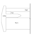
도 1은 일반적인 디스플레이 구조를 도시하고 있다. 도 1에 의하면, 디스플레이는 백보드, 캐비넷, 패드 및 패널로 구성된다. 디스플레이를 구성하는 백보드와 캐비넷의 체결은 도 1에 도시되어 있는 바와 같이 양면테이프를 이용한다. 즉, 백보드와 캐비넷 사이에 양면테이프를 인입하여 백보드와 캐비넷을 체결한다.1 shows a general display structure. According to Figure 1, the display is composed of a backboard, a cabinet, pads and panels. The fastening of the back board and the cabinet constituting the display uses a double-sided tape as shown in FIG. 1. That is, a double-sided tape is inserted between the backboard and the cabinet to fasten the backboard and the cabinet.
즉, 백보드와 패드의 측면이 외부에 노출되지 않기 위해서는 별도의 캐비넷(미들 캐비넷: M/C)을 필요로 하며, 이는 제품 단가의 상승을 불러오게 되며, 별도의 공정을 필요로 한다는 문제점이 있다.That is, a separate cabinet (middle cabinet: M / C) is required in order to prevent the side surfaces of the backboard and the pad from being exposed to the outside, which leads to an increase in product cost, and requires a separate process. .
본 발명이 해결하려는 과제는 별도의 부재없이 패드의 측면이 노출되지 않도록 하는 방안을 제안함에 있다.The problem to be solved by the present invention is to propose a method to prevent the side of the pad from being exposed without a separate member.
본 발명이 해결하려는 다른 과제는 평탄 강성이 우수하며, 측면의 마감 처리가 용이한 공정을 제안함에 있다.Another problem to be solved by the present invention is to propose a process having excellent flat stiffness and easy finishing of side surfaces.
본 발명이 해결하는 또 다른 과제는 제조비용이 절감되는 디스플레이를 제안함에 있다.Another problem to be solved by the present invention is to propose a display in which manufacturing cost is reduced.
본 발명이 해결하려는 또 다른 과제는 내측 헤밍뿐만 아니라 외측 헤밍이 가능한 복합 소재를 제안함에 있다.Another problem to be solved by the present invention is to propose a composite material capable of outer hemming as well as inner hemming.
본 발명이 해결하려는 또 다른 과제는 금속부재로부터 핫 멜트 필름을 용이하게 제거할 수 있는 방안을 제안함에 있다.Another problem to be solved by the present invention is to propose a method for easily removing a hot melt film from a metal member.
이를 위해 본 발명의 상부 금속부재, 수지부재 및 하부 금속부재로 구성된 복합소재를 프레스 가공하는 방법은 상단면에 제1 코팅필름이 접착되며, 하단면에 제2 코팅필름이 접착된 하부 금속부재를 제조하는 단계; 상부 금속부재, 제1 핫 멜트부재, 수지부재, 제2 핫 멜트부재 및 하부 금속부재 순으로 접착된 복합 소재를 제조하는 단계; 상기 복합 소재의 테두리로부터 내측으로 일정 거리 인입된 지점을 제1 커터를 이용하여 상기 하부 금속부재의 상단까지 절삭하는 단계; 절삭된 지점의 외측에 위치하는 상부 금속부재, 제1 핫 멜트부재, 수지부재, 제2 핫 멜트부재를 제거하는 단계; 및 상기 하부 금속부재를 헤밍 다이를 이용하여 180ㅀ 구부려 상기 상부 금속부재와 수지부재가 측면에서 노출되지 않도록 하는 단계를 포함한다.To this end, a method of press processing a composite material composed of an upper metal member, a resin member, and a lower metal member of the present invention includes a lower metal member having a first coating film adhered to the upper surface and a second coating film adhered to the lower surface. Manufacturing; Manufacturing an upper metal member, a first hot-melt member, a resin member, a second hot-melt member, and a lower metal member in the order of bonding the composite material; Cutting a point drawn inward at a certain distance from the rim of the composite material to the top of the lower metal member using a first cutter; Removing the upper metal member, the first hot melt member, the resin member, and the second hot melt member located outside the cut point; And bending the lower metal member 180 ° using a hemming die so that the upper metal member and the resin member are not exposed from the side.
본 발명에 따른 복합소재 프레스 성형 방법은 상대적으로 가장 하단에 위치한 금속부재를 헤밍 다이(지그)를 이용하여 180도 구부려 복합 소재의 절단면이 노출되지 않도록 한다. 이와 같이 금속부재를 헤밍 다이를 이용하여 180 구부려 복합 소재의 절단면이 노출되지 않도록 함으로써 별도로 미들 캐비넷을 사용할 필요가 없게 된다.In the composite material press forming method according to the present invention, a metal member positioned at the lowermost portion is bent 180 degrees using a hemming die (jig) so that the cut surface of the composite material is not exposed. In this way, the metal member is bent 180 using a hemming die so that the cut surface of the composite material is not exposed, thereby eliminating the need to use a middle cabinet.
이와 같이 별도의 미들 캐비넷을 사용하지 않음으로써 제조 단가가 절감되며, 외관의 마감 처리 역시 우수하다는 장점이 있다. In this way, the manufacturing cost is reduced by not using a separate middle cabinet, and the exterior finishing is also excellent.
또한, 본 발명은 내측 헤밍뿐만 아니라 외측 헤밍이 기능한 복합 소재를 제조할 수 있으며, 이를 위해 금속부재로부터 용이하게 핫 멜트부재를 제거할 수 있다.In addition, the present invention can manufacture a composite material having an inner hemming as well as an outer hemming, and for this purpose, the hot melt member can be easily removed from the metal member.
도 1은 일반적인 디스플레이 구조를 도시하고 있다.
도 2는 본 발명의 일실시 예에 따른 복합 소재의 구조를 도시하고 있다.
도 3은 본 발명의 일실시 예에 따른 복합 소재의 가공 과정을 도시하고 있다.
도 4는 본 발명의 일실시 예에 따른 상부 금속부재와 수지부재가 절삭된 이후 복합소재의 가공 과정을 도시하고 있다.
도 5는 본 발명의 일실시 예에 따른 상부 금속부재를 절곡한 이후의 복합소재의 가공 과정을 도시하고 있다.
도 6은 본 발명의 일실시 예에 따른 복합 소재를 가공하는 과정을 도시한 흐름도이다.
도 7은 본 발명의 다른 실시 예에 따른 복합소재 가공 방법을 도시하고 있다.
도 8은 본 발명의 일실시 예에 따른 하부 금속부재에 제1 코팅 필름과 제2 코팅 필름을 접착하는 방안을 도시하고 있다.
도 9는 본 발명의 일실시 예에 따른 복합 소재의 구성을 도시하고 있다.
도 10은 본 발명의 일실시 예에 따른 T 커터를 이용하여 복합소재를 가공하는 부위를 도시하고 있다.
도 11은 본 발명의 일실시 예에 따른 헤밍 다이를 이용하여 하부 금속부재를 헤밍한 예를 도시하고 있다.1 shows a general display structure.
Figure 2 shows the structure of a composite material according to an embodiment of the present invention.
3 shows a process of processing a composite material according to an embodiment of the present invention.
4 shows a process of processing a composite material after the upper metal member and the resin member are cut according to an embodiment of the present invention.
5 illustrates a process of processing a composite material after bending an upper metal member according to an embodiment of the present invention.
6 is a flowchart showing a process of processing a composite material according to an embodiment of the present invention.
7 shows a composite material processing method according to another embodiment of the present invention.
8 shows a method of adhering the first coating film and the second coating film to the lower metal member according to an embodiment of the present invention.
9 shows a configuration of a composite material according to an embodiment of the present invention.
10 is a view showing a portion for processing a composite material using a T cutter according to an embodiment of the present invention.
11 shows an example of hemming a lower metal member using a hemming die according to an embodiment of the present invention.
전술한, 그리고 추가적인 본 발명의 양상들은 첨부된 도면을 참조하여 설명되는 바람직한 실시 예들을 통하여 더욱 명백해질 것이다. 이하에서는 본 발명의 이러한 실시 예를 통해 당업자가 용이하게 이해하고 재현할 수 있도록 상세히 설명하기로 한다.The above and further aspects of the present invention will become more apparent through preferred embodiments described with reference to the accompanying drawings. Hereinafter will be described in detail so that those skilled in the art through this embodiment of the present invention can be easily understood and reproduced.
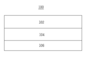
도 2는 본 발명의 일실시 예에 따른 복합 소재를 도시하고 있다. 이하 도 2를 이용하여 본 발명의 일실시 예에 따른 복합 소재에 대해 상세하게 알아보기로 한다.2 shows a composite material according to an embodiment of the present invention. Hereinafter, a composite material according to an embodiment of the present invention will be described in detail with reference to FIG. 2.
도 2에 의하면, 복합 소재(100)는 상부 금속부재(102), 수지부재(104) 및 하부 금속부재(106)를 포함한다. 또한, 도 2에 의하면 복합 소재를 구성하는 각 소재의 종단면(절단면)은 하나의 평면을 갖는다.According to FIG. 2, the
도 3은 본 발명의 일실시 예에 따른 복합 소재의 가공 과정을 도시하고 있다. 이하 도 3을 이용하여 본 발명의 일실시 예에 따른 복합 소재의 가공 과정에 대해 상세하게 알아보기로 한다.3 shows a process of processing a composite material according to an embodiment of the present invention. Hereinafter, a process of processing a composite material according to an embodiment of the present invention will be described in detail with reference to FIG. 3.
상술한 바와 같이 복합소재(100)의 종단면(절단면)은 하나의 평면을 갖는다. 이와 같은 상태에서 커터를 이용하여 복합소재의 종단면(테두리)을 가공한다. 도 3에 도시되어 있는 바와 같이 커터는 'T 커터 '이며, 커터를 이용하여 상부 금속부재(102)와 수지부재(104)를 절삭한다. 이 경우 수지부재(104)가 상부 금속부재(102)보다 상대적으로 많이 절삭한다. 즉, 커터 중 직경이 상대적으로 큰 부분을 이용하여 수지부재(104)를 절삭하며, 직경이 상대적으로 적은 부분을 이용하여 상부 금속부재(102)를 절삭한다. 커터에 의해 복합 소재는 도 3과 같이 상부 금속부재(102)와 수지부재(104)가 절삭된다.As described above, the longitudinal section (cutting surface) of the
도 4는 본 발명의 일실시 예에 따른 상부 금속부재와 상부 금속부재가 절삭된 이후 복합소재의 가공 과정을 도시하고 있다. 이하 도 4를 이용하여 본 발명의 일실시 예에 따른 상부 금속부재와 상부 금속부재가 절삭된 이후 복합소재의 가공 과정에 대해 알아보기로 한다.Figure 4 shows the processing of the composite material after the upper metal member and the upper metal member is cut according to an embodiment of the present invention. Hereinafter, the process of processing the composite material after the upper metal member and the upper metal member are cut according to an embodiment of the present invention will be described with reference to FIG. 4.
도 4에 의하면, 수지부재(104)보다 상대적으로 돌출된 상부 금속부재(102)를 하부 금속부재(106) 방향으로 절곡한다. 상부 금속부재(102)를 하부 금속부재(106) 방향으로 절곡함으로서 수지부재(104)의 종단면은 상부 금속부재(102)에 밀착된다. 도 4는 상부 금속부재(102)가 수지부재(104)의 종단면 전체에 밀착된 상태를 도시하고 있으며, 특히 절곡된 상부 금속부재(102)는 하부 금속부재(106)의 상단면에 밀착된다. 즉, 상부 금속부재(102)은 두 개의 절곡 부위를 갖는다. 물론 돌출된 상부 금속부재(102)의 길이에 따라 상부 금속부재(102)는 하나의 절곡 부위를 가질 수 있다.According to FIG. 4, the
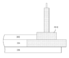
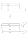
도 5는 본 발명의 일실시 예에 따른 상부 금속부재를 절곡한 이후의 복합소재의 가공 과정을 도시하고 있다. 이하 도 5를 이용하여 본 발명의 일실시 예에 따른 상부 금속부재를 절곡한 이후의 복합소재의 가공 과정에 대해 상세하게 알아보기로 한다.5 illustrates a process of processing a composite material after bending an upper metal member according to an embodiment of the present invention. Hereinafter, a process of processing a composite material after bending an upper metal member according to an embodiment of the present invention will be described in detail with reference to FIG. 5.
도 5에 의하면, 상부 금속부재(102)을 절곡한 이후 헤밍 다이(Hemming die, 프레스)를 이용하여 하부 금속부재(106)를 180ㅀ 구부려 접는다. 이와 같이 헤밍 다이를 이용하여 하부 금속부재(106)를 180ㅀ 구부려 접음으로서 복합 소재의 종단면이 외부로 노출되지 않는다.According to FIG. 5, after bending the
이와 같이 본 발명은 하부 금속부재(106)를 헤딩 다이를 이용하여 180ㅀ 구부림으로서 복합 소재의 테두리(종단면)가 외부로 노출되지 않도록 별도의 부재(미들 캐비넷: M/C)를 이용하여 수지부재(104)의 테두리가 노출되지 않도록 하는 공정을 수행할 필요가 없게 된다.As described above, the present invention is a resin member using a separate member (middle cabinet: M / C) so that the
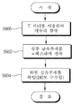
도 6은 본 발명의 일실시 예에 따른 복합 소재를 가공하는 과정을 도시한 흐름도이다. 이하 도 6을 이용하여 본 발명의 일실시 예에 따른 복합 소재를 가공하는 과정에 대해 상세하게 알아보기로 한다.6 is a flowchart showing a process of processing a composite material according to an embodiment of the present invention. Hereinafter, a process of processing a composite material according to an embodiment of the present invention will be described in detail with reference to FIG. 6.
S600단계에서 상부 금속부재(102), 수지부재(104) 및 하부 금속부재(106)로 구성된 복합 소재를 'T 커터'를 이용하여 상부 금속부재(102)와 수지부재(104)의 테두리를 절삭한다. 이 경우 수지부재(104)가 상부 금속부재(102)에 비해 상대적으로 많이 절삭한다.In step S600, the composite material composed of the
S602단계에서 수지부재(104)에 비해 상대적으로 적게 절삭된 상부 금속부재(102)를 하부 금속부재(106) 방향으로 절곡한다. 이 경우, 상부 금속부재(102)는 수지부재(104)의 두께, 수지부재(104)로부터 돌출된 길이에 따라 하나의 절곡 부위 또는 두 개의 절곡 부위를 가질 수 있다.In step S602, the
S604단계에서 하부 금속부재(106)를 헤밍 다이를 이용하여 180ㅀ 구부려 복합소재의 테두리가 외부로 노출되지 않도록 한다.In step S604, the
이와 같이 본 발명은 하부 금속부재(106)를 헤밍 다이를 이용하여 180도 구부림으로서 별도의 부재없이 수지부재(104)의 테두리가 외부로 노출되지 않게 된다.As described above, according to the present invention, the
도 7은 본 발명의 다른 실시 예에 따른 복합소재 가공 방법을 도시하고 있다. 도 7에 의하면 복합 소재는 상부 금속부재(102), 수지부재(104) 및 하부 금속부재(106)를 포함한다. 도 3은 커터를 이용하여 상부 금속부재(102)과 수지부재(104)을 절삭하며, 특히 수지부재(104)를 상대적으로 많이 절삭한다. 이에 비해 도 7은 상부 금속부재(102)과 수지부재(104)를 동일하게 절삭하며, 상부 금속부재(102)의 절곡 과정 역시 수행하지 않는다. 다만, 도 7은 헤밍 다이를 이용하여 하부 금속부재(106)를 180ㅀ 구부리는 공정은 동일하게 수행한다. 따라서 도 7 역시 하부 금속부재(106)에 의해 상부 금속부재(102) 테두리(절단면, 종단면), 수지부재(104)의 테두리(절단면, 종단면)가 외부로 노출되지 않게 되며, 이로 인해 별도의 부재를 이용하여 복합소재의 종단면이 외부로 노출되지 않도록 하는 공정을 수행할 필요가 없다. 7 shows a composite material processing method according to another embodiment of the present invention. According to FIG. 7, the composite material includes an
본 발명은 상부 금속부재, 수지부재 및 하부 금속부재로 형성된 복합 소재에 대해 언급하고 있으나, 이에 한정되는 것은 아니다. 스테인리스(STS)- 알루미늄-스테인리스(STS)로 구성된 복합소재, 알루미늄-냉연철판(SPCC)-알루미늄으로 구성된 복합소재 등 다양한 형태의 복합소재에 적용이 가능하다. 즉, 본원 발명은 적층 구조를 갖는 복합소재의 종단면이 외부로 노출되지 않도록 하는 다양한 소재에 적용이 가능하다. 이 경우 최하단에 위치한 소재를 허밍 다이를 이용하여 180ㅀ 구부림으로 상술한 효과를 획득할 수 있다.The present invention refers to a composite material formed of an upper metal member, a resin member, and a lower metal member, but is not limited thereto. It is applicable to various types of composite materials, such as composite materials composed of stainless steel (STS) -aluminum-stainless steel (STS), and composite materials composed of aluminum-cold rolled steel plate (SPCC) -aluminum. That is, the present invention can be applied to various materials that do not expose the longitudinal section of the composite material having a laminated structure to the outside. In this case, the above-described effect can be obtained by bending the material located at the bottom of the bottom using a humming die by 180 ㅀ.
상술한 발명에서는 설명되지 않았으나, 상부 금속부재와 수지부재 사이에는 제1 핫 멜트부재(제1 핫 멜트 필름: Hot melt film)에 의해 접착되며, 수지부재와 하부 금속부재 사이에는 제2 핫 멜트부재(제2 핫 멜트 필름)에 의해 접착된다.Although not described in the above-described invention, it is adhered by a first hot melt member (first hot melt film) between the upper metal member and the resin member, and the second hot melt member between the resin member and the lower metal member. (Second hot melt film).
또한, 수지부재와 하부 금속부재 사이에는 제2 핫 멜트부재에 의해 접착된 상태에서 코팅 필름을 접착되지 않으므로 하부 금속부재는 내측 헤밍만 가능하다. 따라서 헤밍 다이를 이용하여 하부 금속부재를 내측으로 헤밍하는 방안과 외측으로 헤밍하는 방안이 요구된다.In addition, since the coating film is not adhered between the resin member and the lower metal member in the state of being adhered by the second hot melt member, the lower metal member is only capable of inner hemming. Therefore, a method of hemming the lower metal member inward and a method of hemming outward is required using a hemming die.
도 8은 본 발명의 일실시 예에 따른 하부 금속부재에 제1 코팅 필름과 제2 코팅 필름을 접착하는 방안을 도시하고 있다. 이하 도 8을 이용하여 본 발명의 일실시 예에 따른 하부 금속부재에 제1 코팅 필름과 제2 코팅 필름을 접착하는 방안에 대해 상세하게 알아보기로 한다.8 shows a method of adhering the first coating film and the second coating film to the lower metal member according to an embodiment of the present invention. Hereinafter, a method of bonding the first coating film and the second coating film to the lower metal member according to an embodiment of the present invention will be described in detail with reference to FIG. 8.
도 8에 의하면, 하부 금속부재 하단면에 제2 코팅 필름이 접착되며, 상단면에 제1 코팅 필름이 접착된다. 제2 코팅 필름은 하부 금속부재의 하단면의 전체에 접착되는 반면, 제1 코팅 필름은 하부 금속부재의 상단면에서 사다리 형상으로 접착된다. 즉, 제1 코팅 필름은 하부 금속부재의 제1 방향인 양 측에 접착되는 동시에 제1 방향과 직각 방향인 제2 방향으로 일정 간격 이격된 상태로 접착된다.According to FIG. 8, the second coating film is adhered to the lower surface of the lower metal member, and the first coating film is adhered to the upper surface. The second coating film is adhered to the entire lower surface of the lower metal member, while the first coating film is adhered in a ladder shape from the upper surface of the lower metal member. That is, the first coating film is adhered to both sides, which is the first direction of the lower metal member, and at the same time, spaced apart at regular intervals in the second direction perpendicular to the first direction.
부연하여 설명하면 먼저 하부 금속부재의 하단면에 제2 코팅 필름을 접착한 이후 하부 금속부재를 뒤집어 하부 금속부재의 상단면에 제1 코팅 필름을 접착한다.To further explain, first, the second coating film is adhered to the lower surface of the lower metal member, then the lower metal member is turned over and the first coating film is adhered to the upper surface of the lower metal member.
도 9는 본 발명의 일실시 예에 따른 복합 소재의 구성을 도시하고 있다. 도 9에 의하면 복합 소재는 상단으로부터 상부 금속부재, 제1 핫 멜트부재, 수지부재, 제2 핫 멜트부재 및 하부 금속부재 순으로 접착된다. 물론 상술한 바와 같이 하부 금속부재는 상단면에 제1 코팅 필름이 접착되며, 하단면에 제2 코팅 필름이 접착된다. 또한, 제1 코팅 필름에 의해 제1 코팅 필름이 접착된 부분에는 제2 핫 멜트 필름이 하부 금속부재에 직접 접착되지 않는다.9 shows a configuration of a composite material according to an embodiment of the present invention. According to FIG. 9, the composite material is adhered in order from the top to the upper metal member, the first hot melt member, the resin member, the second hot melt member, and the lower metal member. Of course, as described above, the lower metal member has a first coating film adhered to the upper surface, and a second coating film adheres to the lower surface. In addition, the second hot melt film is not directly bonded to the lower metal member to the portion where the first coating film is adhered by the first coating film.
이후 복합 소재는 커터를 이용하여 일정 간격으로 절단한다. 즉, 커터를 이용하여 복합소재를 제2 방향으로 절단하며, 특히 제2 방향으로 형성된 제1 코팅 필름의 중간 부분을 절단하여 사각형 형상의 복합 소재를 제조한다. Thereafter, the composite material is cut at regular intervals using a cutter. That is, the composite material is cut in the second direction using a cutter, and in particular, the middle portion of the first coating film formed in the second direction is cut to produce a rectangular composite material.
도 10은 본 발명의 일실시 예에 따른 T 커터를 이용하여 복합소재를 가공하는 부위를 도시하고 있다. 이하 도 10을 이용하여 본 발명의 일실시 예에 따른 T 커터를 이용하여 복합소재를 가공하는 부위에 대해 상세하게 알아보기로 한다.10 is a view showing a portion for processing a composite material using a T cutter according to an embodiment of the present invention. Hereinafter, a portion for processing a composite material using a T cutter according to an embodiment of the present invention will be described in detail with reference to FIG. 10.
도 10에 의하면, T 커터를 이용하여 복합소재를 가공하는 부위는 제2 코팅 필름이 접착된 부위와 접착되지 않은 부위의 경계선을 중심으로 일정폭만큼 절삭한다. 물론 상술한 바와 같이 모든 부위를 절삭하는 것이 아니라 하부 금속부재의 상단까지 절삭한다.According to FIG. 10, a portion for processing a composite material by using a T cutter is cut by a predetermined width around a boundary line between a portion where the second coating film is adhered and a portion not adhered. Of course, not all parts are cut as described above, but to the top of the lower metal member.
복합소재에서 하부 금속부재의 상단이 절삭된 상태에서 테두리 부분에 형성된 제2 핫 멜트부재를 제거한다. 상술한 바와 같이 제1 코팅 필름에 의해 제2 핫 멜트부재가 제1 코팅 필름(또는 하부 금속부재)에 접착되지 않으므로 간단하게 하부 금속부재로부터 제2 핫 멜트부재를 제거할 수 있다. 물론 제2 핫 멜트부재를 제거하면, 제2 핫 멜트부재의 상단에 위치한 수지부재, 제1 핫 멜트부재 및 상부 금속부재 역시 제거된다.In the composite material, the second hot melt member formed on the edge portion is removed while the upper end of the lower metal member is cut. As described above, since the second hot melt member is not adhered to the first coating film (or the lower metal member) by the first coating film, the second hot melt member can be simply removed from the lower metal member. Of course, when the second hot melt member is removed, the resin member, the first hot melt member, and the upper metal member located on the top of the second hot melt member are also removed.
도 10은 복합 소재에서 제2 핫 멜트부재가 제거된 상태를 도시하고 있다. 제2 핫 멜트부재가 제거된 복합 소재는 상단면에 제1 코팅 필름이, 하단면에 제2 코팅 필름이 접착된 하부 금속부재만이 남아있게 된다.10 shows a state in which the second hot melt member is removed from the composite material. In the composite material from which the second hot melt member is removed, only the lower metal member to which the first coating film is adhered to the upper surface and the second coating film is adhered to the lower surface remains.
도 11은 본 발명의 일실시 예에 따른 헤밍 다이를 이용하여 하부 금속부재를 헤밍한 예를 도시하고 있다. 도 11에 도시되어 있는 바와 같이 하부 금속부재는 상단면에 제1 코팅 필름이, 하단면에 제2 코팅 필름이 접착되어 있으므로 헤밍 다이를 이용하여 내측 헤밍 뿐만 아니라 외측 헤밍도 가능하다.11 shows an example of hemming a lower metal member using a hemming die according to an embodiment of the present invention. As illustrated in FIG. 11, since the first coating film is adhered to the upper surface of the lower metal member and the second coating film is attached to the lower surface of the lower metal member, it is possible to use the hemming die as well as inner hemming and outer hemming.
본 발명은 도면에 도시된 일실시 예를 참고로 설명되었으나, 이는 예시적인 것에 불과하며, 본 기술 분야의 통상의 지식을 가진 자라면 이로부터 다양한 변형 및 균등한 타 실시예가 가능하다는 점을 이해할 것이다. The present invention has been described with reference to one embodiment shown in the drawings, but this is merely exemplary, and those skilled in the art will understand that various modifications and other equivalent embodiments are possible therefrom. .
100: 복합 소재
102: 상부 금속부재
104: 수지부재
106: 하부 금속부재100: composite material 102: upper metal member
104: resin member 106: lower metal member
Claims (6)
상단면에 제1 코팅필름이 접착되며, 하단면에 제2 코팅필름이 접착된 하부 금속부재를 제조하는 단계;
상부 금속부재, 제1 핫 멜트부재, 수지부재, 제2 핫 멜트부재 및 하부 금속부재 순으로 접착된 복합 소재를 제조하는 단계;
상기 복합 소재의 테두리로부터 내측으로 일정 거리 인입된 지점을 제1 커터를 이용하여 상기 하부 금속부재의 상단까지 절삭하는 단계;
절삭된 지점의 외측에 위치하는 상부 금속부재, 제1 핫 멜트부재, 수지부재, 제2 핫 멜트부재를 제거하는 단계; 및
상기 하부 금속부재를 헤밍 다이를 이용하여 180ㅀ 구부려 상기 상부 금속부재와 수지부재가 측면에서 노출되지 않도록 하는 단계를 포함함을 특징으로 하는 복합소재를 프레스 가공하는 방법.
In the method of pressing the composite material consisting of the upper metal member, the resin member and the lower metal member,
Manufacturing a lower metal member having a first coating film adhered to an upper surface and a second coating film adhered to a lower surface;
Manufacturing an upper metal member, a first hot-melt member, a resin member, a second hot-melt member, and a lower metal member in the order of bonding the composite material;
Cutting a point drawn inward at a certain distance from the rim of the composite material to the top of the lower metal member using a first cutter;
Removing the upper metal member, the first hot melt member, the resin member, and the second hot melt member located outside the cut point; And
And bending the lower metal member 180 ° using a hemming die to prevent the upper metal member and the resin member from being exposed from the side.
상기 제2 코팅필름은 하부 금속부재의 하단면 전체에 접착되며, 상기 제1 코팅필름은 하부 금속부재의 상단면 중 일부에 접착됨을 특징으로 하는 복합소재를 프레스 가공하는 방법.
According to claim 1,
The second coating film is attached to the entire lower surface of the lower metal member, the first coating film is a method of pressing a composite material characterized in that it is bonded to a portion of the upper surface of the lower metal member.
The composite material according to claim 2, wherein the first coating film is adhered to both sides in a first direction of the lower metal member, and is spaced apart at regular intervals in a second direction perpendicular to the first direction. How to press.
제2 커터를 이용하여 제2 방향으로 접착된 제1 코팅필름의 중간 부분을 절단하여 사각형 형상의 복합소재를 제조함을 특징으로 하는 복합소재를 프레스 가공하는 방법.
According to claim 3, After the step of manufacturing the composite material,
A method of press-working a composite material, characterized in that a square-shaped composite material is manufactured by cutting an intermediate portion of a first coating film adhered in a second direction using a second cutter.
제1 코팅필름이 접착된 부분과 제1 코팅필름이 접착되지 않은 부분이 포함되도록 일정폭만큼 절삭함을 특징으로 하는 복합소재를 프레스 가공하는 방법.
According to claim 4, Using the first cutter to cut to the top of the lower metal member,
A method of pressing a composite material, characterized in that it cuts by a certain width so that a portion to which the first coating film is adhered and a portion to which the first coating film is not adhered are included.
Priority Applications (6)
| Application Number | Priority Date | Filing Date | Title |
|---|---|---|---|
| KR1020180129584A KR102212888B1 (en) | 2018-10-29 | 2018-10-29 | Method for press molding of compound material |
| EP19161506.1A EP3646960B1 (en) | 2018-10-29 | 2019-03-08 | Press forming method for composite material |
| US16/297,203 US10811628B2 (en) | 2018-10-29 | 2019-03-08 | Press forming method for composite material |
| CN201910242909.0A CN110216890A (en) | 2018-10-29 | 2019-03-28 | The compression-moulding methods of composite material |
| CN201920408230.XU CN210059443U (en) | 2018-10-29 | 2019-03-28 | Composite material compression molding device |
| JP2019066514A JP6698905B2 (en) | 2018-10-29 | 2019-03-29 | Method for manufacturing laminated material casing member |
Applications Claiming Priority (1)
| Application Number | Priority Date | Filing Date | Title |
|---|---|---|---|
| KR1020180129584A KR102212888B1 (en) | 2018-10-29 | 2018-10-29 | Method for press molding of compound material |
Publications (2)
| Publication Number | Publication Date |
|---|---|
| KR20200048000A true KR20200048000A (en) | 2020-05-08 |
| KR102212888B1 KR102212888B1 (en) | 2021-02-05 |
Family
ID=65729159
Family Applications (1)
| Application Number | Title | Priority Date | Filing Date |
|---|---|---|---|
| KR1020180129584A KR102212888B1 (en) | 2018-10-29 | 2018-10-29 | Method for press molding of compound material |
Country Status (5)
| Country | Link |
|---|---|
| US (1) | US10811628B2 (en) |
| EP (1) | EP3646960B1 (en) |
| JP (1) | JP6698905B2 (en) |
| KR (1) | KR102212888B1 (en) |
| CN (2) | CN110216890A (en) |
Cited By (1)
| Publication number | Priority date | Publication date | Assignee | Title |
|---|---|---|---|---|
| CN112829328A (en) * | 2020-12-31 | 2021-05-25 | 德奥福臻越智能机器人(杭州)有限公司 | Lower die device with edge covering function and skin adhering and edge covering method |
Families Citing this family (4)
| Publication number | Priority date | Publication date | Assignee | Title |
|---|---|---|---|---|
| CN112829329B (en) * | 2020-12-31 | 2024-07-12 | 臻越自动化技术(上海)有限公司 | Lower die device and method for adhering surface skin of automobile armrest |
| CN113561511B (en) * | 2021-07-01 | 2023-02-03 | 东莞市豪顺精密科技有限公司 | Steel-plastic back plate and manufacturing method thereof |
| KR102591102B1 (en) | 2021-09-30 | 2023-10-19 | (주)인지디스플레이 | Press curling method of composite panel for display device |
| KR102515993B1 (en) | 2021-09-30 | 2023-03-30 | 주식회사 인지디스플레이 | Press curling method of chassis for display device |
Citations (4)
| Publication number | Priority date | Publication date | Assignee | Title |
|---|---|---|---|---|
| KR20140094694A (en) | 2013-01-21 | 2014-07-31 | 희성전자 주식회사 | Liquid Crystal Display |
| KR20160019751A (en) | 2014-08-12 | 2016-02-22 | 엘지디스플레이 주식회사 | Organic light emitting diode |
| KR20180062609A (en) * | 2016-12-01 | 2018-06-11 | 주식회사 오성디스플레이 | Method for press molding of compound material |
| KR20180115128A (en) * | 2017-04-12 | 2018-10-22 | 주식회사 서연이화 | Method of Manufacturing Complex Material Structure Comprising Real Material Film |
Family Cites Families (22)
| Publication number | Priority date | Publication date | Assignee | Title |
|---|---|---|---|---|
| JPS62144823A (en) * | 1985-12-18 | 1987-06-29 | Honma Seisakusho:Kk | Curling method for metallic pan of the like |
| JPH05495A (en) * | 1991-06-24 | 1993-01-08 | Kobe Steel Ltd | Method for processing composite metal sheet |
| JP2000269663A (en) * | 1999-03-17 | 2000-09-29 | Nisshin Kogyo Kk | Case for electronic component and its manufacture |
| US8057896B2 (en) * | 2005-01-06 | 2011-11-15 | Selig Sealing Products, Inc. | Pull-tab sealing member with improved heat distribution for a container |
| KR100769425B1 (en) * | 2006-09-21 | 2007-10-22 | 삼성에스디아이 주식회사 | Organic light-emitting display device |
| KR100857690B1 (en) * | 2007-05-30 | 2008-09-08 | 삼성에스디아이 주식회사 | Organic light emitting display device |
| US8797473B2 (en) * | 2007-09-12 | 2014-08-05 | Japan Display West Inc. | Electro-optical device having a frame including a conduction part and a resin part |
| CN101245659A (en) * | 2008-03-21 | 2008-08-20 | 朱金龙 | Nano-fluorine carbon self-cleaning metal composite board and manufacturing method thereof |
| JP2010256702A (en) * | 2009-04-27 | 2010-11-11 | Casio Computer Co Ltd | Display device |
| JP2011017856A (en) * | 2009-07-08 | 2011-01-27 | Casio Computer Co Ltd | Case and display |
| KR101771162B1 (en) * | 2010-12-14 | 2017-08-25 | 삼성디스플레이 주식회사 | Organic light emitting diode display |
| JP5712944B2 (en) * | 2011-03-17 | 2015-05-07 | 東レ株式会社 | Method for producing metal composite |
| CN102975410A (en) * | 2012-11-29 | 2013-03-20 | 江苏协诚科技发展有限公司 | Grade-A fireproof aluminium alloy composite board |
| CN103331964A (en) * | 2013-07-24 | 2013-10-02 | 朱孟领 | Composite plate and preparation method thereof |
| KR102201943B1 (en) * | 2013-09-23 | 2021-01-12 | 삼성디스플레이 주식회사 | Display device |
| CN105034479A (en) * | 2015-05-29 | 2015-11-11 | 杨建军 | Metallized layer dielectric plate of polymethacrylimide foam base material |
| CN104993063A (en) * | 2015-07-17 | 2015-10-21 | 京东方科技集团股份有限公司 | A package member and a manufacture method therefor, and an OLED device |
| EP3163362B1 (en) * | 2015-10-27 | 2019-03-13 | LG Electronics Inc. | Display device |
| KR102655011B1 (en) * | 2016-05-30 | 2024-04-08 | 엘지디스플레이 주식회사 | Display device |
| KR20180089042A (en) * | 2017-01-31 | 2018-08-08 | 주식회사 오성디스플레이 | Method for molding a back cover of a display and a mold for forming a back cover |
| WO2019045124A1 (en) * | 2017-08-28 | 2019-03-07 | 엘지전자(주) | Display device |
| US11044820B2 (en) * | 2017-10-30 | 2021-06-22 | Lg Display Co., Ltd. | Display device |
-
2018
- 2018-10-29 KR KR1020180129584A patent/KR102212888B1/en active IP Right Grant
-
2019
- 2019-03-08 US US16/297,203 patent/US10811628B2/en active Active
- 2019-03-08 EP EP19161506.1A patent/EP3646960B1/en active Active
- 2019-03-28 CN CN201910242909.0A patent/CN110216890A/en active Pending
- 2019-03-28 CN CN201920408230.XU patent/CN210059443U/en not_active Expired - Fee Related
- 2019-03-29 JP JP2019066514A patent/JP6698905B2/en active Active
Patent Citations (4)
| Publication number | Priority date | Publication date | Assignee | Title |
|---|---|---|---|---|
| KR20140094694A (en) | 2013-01-21 | 2014-07-31 | 희성전자 주식회사 | Liquid Crystal Display |
| KR20160019751A (en) | 2014-08-12 | 2016-02-22 | 엘지디스플레이 주식회사 | Organic light emitting diode |
| KR20180062609A (en) * | 2016-12-01 | 2018-06-11 | 주식회사 오성디스플레이 | Method for press molding of compound material |
| KR20180115128A (en) * | 2017-04-12 | 2018-10-22 | 주식회사 서연이화 | Method of Manufacturing Complex Material Structure Comprising Real Material Film |
Cited By (1)
| Publication number | Priority date | Publication date | Assignee | Title |
|---|---|---|---|---|
| CN112829328A (en) * | 2020-12-31 | 2021-05-25 | 德奥福臻越智能机器人(杭州)有限公司 | Lower die device with edge covering function and skin adhering and edge covering method |
Also Published As
| Publication number | Publication date |
|---|---|
| KR102212888B1 (en) | 2021-02-05 |
| JP6698905B2 (en) | 2020-05-27 |
| US10811628B2 (en) | 2020-10-20 |
| CN210059443U (en) | 2020-02-14 |
| CN110216890A (en) | 2019-09-10 |
| US20200136084A1 (en) | 2020-04-30 |
| EP3646960B1 (en) | 2021-08-18 |
| JP2020072466A (en) | 2020-05-07 |
| EP3646960A1 (en) | 2020-05-06 |
Similar Documents
| Publication | Publication Date | Title |
|---|---|---|
| KR20200048000A (en) | Method for press molding of compound material | |
| KR102348956B1 (en) | Multi vision display apparatus using a flexible display device | |
| JP4960762B2 (en) | Display device and manufacturing method thereof | |
| JP6720240B2 (en) | Method for manufacturing laminated plate casing member | |
| EP2854194A1 (en) | Organic light emitting diode display panel and organic light emitting diode display device containing the same | |
| SG142140A1 (en) | Display device and method of manufacturing thereof | |
| CN109192880B (en) | Display panel and manufacturing method thereof | |
| JP2017112108A (en) | Organic light-emitting display device | |
| GB0811058D0 (en) | Sealed switchable glazing | |
| JP5362336B2 (en) | Method for manufacturing an electronic display device covered with a protective plate | |
| US20220310946A1 (en) | Flexible base substrate, display panel and display device | |
| US11065662B2 (en) | Press forming method for compound material | |
| KR102263379B1 (en) | Method for press molding of compound material | |
| JP4682883B2 (en) | Method for dividing bonded substrates | |
| JP2007073225A5 (en) | ||
| KR101233349B1 (en) | Method for manufacturing organic light emitting diode display device | |
| KR102437027B1 (en) | Organic Light Emtting Display Device | |
| CN110289290A (en) | A kind of display master blank and preparation method thereof, electroluminescence display panel | |
| KR100922354B1 (en) | Organic light emitting diode display | |
| US10483437B2 (en) | Display device | |
| US10622579B2 (en) | Organic light-emitting diode (OLED) display panel, backplane attaching method and backplane attaching device | |
| CN110315838B (en) | Compression molding method of composite material | |
| JP2004288482A (en) | Organic el panel | |
| JP2007095622A (en) | Organic el display panel | |
| KR101814177B1 (en) | Method for cap material manufactured of OLED |
Legal Events
| Date | Code | Title | Description |
|---|---|---|---|
| E902 | Notification of reason for refusal | ||
| E90F | Notification of reason for final refusal | ||
| E701 | Decision to grant or registration of patent right | ||
| GRNT | Written decision to grant |