KR20200043440A - Grain-oriented electrical steel sheet - Google Patents
Grain-oriented electrical steel sheet Download PDFInfo
- Publication number
- KR20200043440A KR20200043440A KR1020207008121A KR20207008121A KR20200043440A KR 20200043440 A KR20200043440 A KR 20200043440A KR 1020207008121 A KR1020207008121 A KR 1020207008121A KR 20207008121 A KR20207008121 A KR 20207008121A KR 20200043440 A KR20200043440 A KR 20200043440A
- Authority
- KR
- South Korea
- Prior art keywords
- steel sheet
- grain
- magnetic domain
- oriented electrical
- less
- Prior art date
Links
Images


Classifications
-
- C—CHEMISTRY; METALLURGY
- C21—METALLURGY OF IRON
- C21D—MODIFYING THE PHYSICAL STRUCTURE OF FERROUS METALS; GENERAL DEVICES FOR HEAT TREATMENT OF FERROUS OR NON-FERROUS METALS OR ALLOYS; MAKING METAL MALLEABLE, e.g. BY DECARBURISATION OR TEMPERING
- C21D8/00—Modifying the physical properties by deformation combined with, or followed by, heat treatment
- C21D8/12—Modifying the physical properties by deformation combined with, or followed by, heat treatment during manufacturing of articles with special electromagnetic properties
- C21D8/1216—Modifying the physical properties by deformation combined with, or followed by, heat treatment during manufacturing of articles with special electromagnetic properties the working step(s) being of interest
- C21D8/1222—Hot rolling
-
- C—CHEMISTRY; METALLURGY
- C21—METALLURGY OF IRON
- C21D—MODIFYING THE PHYSICAL STRUCTURE OF FERROUS METALS; GENERAL DEVICES FOR HEAT TREATMENT OF FERROUS OR NON-FERROUS METALS OR ALLOYS; MAKING METAL MALLEABLE, e.g. BY DECARBURISATION OR TEMPERING
- C21D8/00—Modifying the physical properties by deformation combined with, or followed by, heat treatment
- C21D8/12—Modifying the physical properties by deformation combined with, or followed by, heat treatment during manufacturing of articles with special electromagnetic properties
- C21D8/1277—Modifying the physical properties by deformation combined with, or followed by, heat treatment during manufacturing of articles with special electromagnetic properties involving a particular surface treatment
- C21D8/1283—Application of a separating or insulating coating
-
- C—CHEMISTRY; METALLURGY
- C21—METALLURGY OF IRON
- C21D—MODIFYING THE PHYSICAL STRUCTURE OF FERROUS METALS; GENERAL DEVICES FOR HEAT TREATMENT OF FERROUS OR NON-FERROUS METALS OR ALLOYS; MAKING METAL MALLEABLE, e.g. BY DECARBURISATION OR TEMPERING
- C21D6/00—Heat treatment of ferrous alloys
- C21D6/005—Heat treatment of ferrous alloys containing Mn
-
- C—CHEMISTRY; METALLURGY
- C21—METALLURGY OF IRON
- C21D—MODIFYING THE PHYSICAL STRUCTURE OF FERROUS METALS; GENERAL DEVICES FOR HEAT TREATMENT OF FERROUS OR NON-FERROUS METALS OR ALLOYS; MAKING METAL MALLEABLE, e.g. BY DECARBURISATION OR TEMPERING
- C21D6/00—Heat treatment of ferrous alloys
- C21D6/008—Heat treatment of ferrous alloys containing Si
-
- C—CHEMISTRY; METALLURGY
- C21—METALLURGY OF IRON
- C21D—MODIFYING THE PHYSICAL STRUCTURE OF FERROUS METALS; GENERAL DEVICES FOR HEAT TREATMENT OF FERROUS OR NON-FERROUS METALS OR ALLOYS; MAKING METAL MALLEABLE, e.g. BY DECARBURISATION OR TEMPERING
- C21D8/00—Modifying the physical properties by deformation combined with, or followed by, heat treatment
- C21D8/12—Modifying the physical properties by deformation combined with, or followed by, heat treatment during manufacturing of articles with special electromagnetic properties
- C21D8/1216—Modifying the physical properties by deformation combined with, or followed by, heat treatment during manufacturing of articles with special electromagnetic properties the working step(s) being of interest
- C21D8/1233—Cold rolling
-
- C—CHEMISTRY; METALLURGY
- C21—METALLURGY OF IRON
- C21D—MODIFYING THE PHYSICAL STRUCTURE OF FERROUS METALS; GENERAL DEVICES FOR HEAT TREATMENT OF FERROUS OR NON-FERROUS METALS OR ALLOYS; MAKING METAL MALLEABLE, e.g. BY DECARBURISATION OR TEMPERING
- C21D8/00—Modifying the physical properties by deformation combined with, or followed by, heat treatment
- C21D8/12—Modifying the physical properties by deformation combined with, or followed by, heat treatment during manufacturing of articles with special electromagnetic properties
- C21D8/1244—Modifying the physical properties by deformation combined with, or followed by, heat treatment during manufacturing of articles with special electromagnetic properties the heat treatment(s) being of interest
- C21D8/1261—Modifying the physical properties by deformation combined with, or followed by, heat treatment during manufacturing of articles with special electromagnetic properties the heat treatment(s) being of interest following hot rolling
-
- C—CHEMISTRY; METALLURGY
- C21—METALLURGY OF IRON
- C21D—MODIFYING THE PHYSICAL STRUCTURE OF FERROUS METALS; GENERAL DEVICES FOR HEAT TREATMENT OF FERROUS OR NON-FERROUS METALS OR ALLOYS; MAKING METAL MALLEABLE, e.g. BY DECARBURISATION OR TEMPERING
- C21D9/00—Heat treatment, e.g. annealing, hardening, quenching or tempering, adapted for particular articles; Furnaces therefor
- C21D9/46—Heat treatment, e.g. annealing, hardening, quenching or tempering, adapted for particular articles; Furnaces therefor for sheet metals
-
- C—CHEMISTRY; METALLURGY
- C22—METALLURGY; FERROUS OR NON-FERROUS ALLOYS; TREATMENT OF ALLOYS OR NON-FERROUS METALS
- C22C—ALLOYS
- C22C38/00—Ferrous alloys, e.g. steel alloys
-
- C—CHEMISTRY; METALLURGY
- C22—METALLURGY; FERROUS OR NON-FERROUS ALLOYS; TREATMENT OF ALLOYS OR NON-FERROUS METALS
- C22C—ALLOYS
- C22C38/00—Ferrous alloys, e.g. steel alloys
- C22C38/001—Ferrous alloys, e.g. steel alloys containing N
-
- C—CHEMISTRY; METALLURGY
- C22—METALLURGY; FERROUS OR NON-FERROUS ALLOYS; TREATMENT OF ALLOYS OR NON-FERROUS METALS
- C22C—ALLOYS
- C22C38/00—Ferrous alloys, e.g. steel alloys
- C22C38/002—Ferrous alloys, e.g. steel alloys containing In, Mg, or other elements not provided for in one single group C22C38/001 - C22C38/60
-
- C—CHEMISTRY; METALLURGY
- C22—METALLURGY; FERROUS OR NON-FERROUS ALLOYS; TREATMENT OF ALLOYS OR NON-FERROUS METALS
- C22C—ALLOYS
- C22C38/00—Ferrous alloys, e.g. steel alloys
- C22C38/02—Ferrous alloys, e.g. steel alloys containing silicon
-
- C—CHEMISTRY; METALLURGY
- C22—METALLURGY; FERROUS OR NON-FERROUS ALLOYS; TREATMENT OF ALLOYS OR NON-FERROUS METALS
- C22C—ALLOYS
- C22C38/00—Ferrous alloys, e.g. steel alloys
- C22C38/04—Ferrous alloys, e.g. steel alloys containing manganese
-
- C—CHEMISTRY; METALLURGY
- C22—METALLURGY; FERROUS OR NON-FERROUS ALLOYS; TREATMENT OF ALLOYS OR NON-FERROUS METALS
- C22C—ALLOYS
- C22C38/00—Ferrous alloys, e.g. steel alloys
- C22C38/06—Ferrous alloys, e.g. steel alloys containing aluminium
-
- C—CHEMISTRY; METALLURGY
- C22—METALLURGY; FERROUS OR NON-FERROUS ALLOYS; TREATMENT OF ALLOYS OR NON-FERROUS METALS
- C22C—ALLOYS
- C22C38/00—Ferrous alloys, e.g. steel alloys
- C22C38/16—Ferrous alloys, e.g. steel alloys containing copper
-
- C—CHEMISTRY; METALLURGY
- C23—COATING METALLIC MATERIAL; COATING MATERIAL WITH METALLIC MATERIAL; CHEMICAL SURFACE TREATMENT; DIFFUSION TREATMENT OF METALLIC MATERIAL; COATING BY VACUUM EVAPORATION, BY SPUTTERING, BY ION IMPLANTATION OR BY CHEMICAL VAPOUR DEPOSITION, IN GENERAL; INHIBITING CORROSION OF METALLIC MATERIAL OR INCRUSTATION IN GENERAL
- C23C—COATING METALLIC MATERIAL; COATING MATERIAL WITH METALLIC MATERIAL; SURFACE TREATMENT OF METALLIC MATERIAL BY DIFFUSION INTO THE SURFACE, BY CHEMICAL CONVERSION OR SUBSTITUTION; COATING BY VACUUM EVAPORATION, BY SPUTTERING, BY ION IMPLANTATION OR BY CHEMICAL VAPOUR DEPOSITION, IN GENERAL
- C23C22/00—Chemical surface treatment of metallic material by reaction of the surface with a reactive liquid, leaving reaction products of surface material in the coating, e.g. conversion coatings, passivation of metals
-
- H—ELECTRICITY
- H01—ELECTRIC ELEMENTS
- H01F—MAGNETS; INDUCTANCES; TRANSFORMERS; SELECTION OF MATERIALS FOR THEIR MAGNETIC PROPERTIES
- H01F1/00—Magnets or magnetic bodies characterised by the magnetic materials therefor; Selection of materials for their magnetic properties
- H01F1/01—Magnets or magnetic bodies characterised by the magnetic materials therefor; Selection of materials for their magnetic properties of inorganic materials
- H01F1/03—Magnets or magnetic bodies characterised by the magnetic materials therefor; Selection of materials for their magnetic properties of inorganic materials characterised by their coercivity
- H01F1/12—Magnets or magnetic bodies characterised by the magnetic materials therefor; Selection of materials for their magnetic properties of inorganic materials characterised by their coercivity of soft-magnetic materials
- H01F1/14—Magnets or magnetic bodies characterised by the magnetic materials therefor; Selection of materials for their magnetic properties of inorganic materials characterised by their coercivity of soft-magnetic materials metals or alloys
- H01F1/147—Alloys characterised by their composition
-
- H—ELECTRICITY
- H01—ELECTRIC ELEMENTS
- H01F—MAGNETS; INDUCTANCES; TRANSFORMERS; SELECTION OF MATERIALS FOR THEIR MAGNETIC PROPERTIES
- H01F1/00—Magnets or magnetic bodies characterised by the magnetic materials therefor; Selection of materials for their magnetic properties
- H01F1/01—Magnets or magnetic bodies characterised by the magnetic materials therefor; Selection of materials for their magnetic properties of inorganic materials
- H01F1/03—Magnets or magnetic bodies characterised by the magnetic materials therefor; Selection of materials for their magnetic properties of inorganic materials characterised by their coercivity
- H01F1/12—Magnets or magnetic bodies characterised by the magnetic materials therefor; Selection of materials for their magnetic properties of inorganic materials characterised by their coercivity of soft-magnetic materials
- H01F1/14—Magnets or magnetic bodies characterised by the magnetic materials therefor; Selection of materials for their magnetic properties of inorganic materials characterised by their coercivity of soft-magnetic materials metals or alloys
- H01F1/16—Magnets or magnetic bodies characterised by the magnetic materials therefor; Selection of materials for their magnetic properties of inorganic materials characterised by their coercivity of soft-magnetic materials metals or alloys in the form of sheets
-
- C—CHEMISTRY; METALLURGY
- C22—METALLURGY; FERROUS OR NON-FERROUS ALLOYS; TREATMENT OF ALLOYS OR NON-FERROUS METALS
- C22C—ALLOYS
- C22C38/00—Ferrous alloys, e.g. steel alloys
- C22C38/60—Ferrous alloys, e.g. steel alloys containing lead, selenium, tellurium, or antimony, or more than 0.04% by weight of sulfur
Abstract
본 발명에 따라, 강판의 표리면에 소정의 포스테라이트를 주성분으로 하는 피막을 갖고, 상기 강판의 표면에, 복수 개의 홈을 갖는 방향성 전기 강판에 대해, 상기 홈은, 평균 깊이가 상기 강판의 두께의 6 % 이상 및 홈 상호간의 거리가 1 ∼ 15 ㎜ 이고, 주파수 50 Hz 및 최대 자속 밀도 1.5 T 로 교류 자화시켰을 때의 비투자율 μr15/50 이 35000 이상이고, 상기 강판의 압연 방향과 직교하는 단면의, 상기 강판과 상기 피막의 계면에 있어서 상기 피막의 연속 부분으로부터 이간되어 고립되는 부분의 존재 빈도를 0.3 개/㎛ 이하로 함으로써, 방향성 전기 강판의 추가적인 저철손화를 실현할 수 있다.According to the present invention, for a grain-oriented electrical steel sheet having a coating having a predetermined forsterite as a main component on the front and back surfaces of the steel sheet and having a plurality of grooves on the surface of the steel sheet, the groove has an average depth of the steel sheet. 6% or more of the thickness and the distance between the grooves is 1 to 15 mm, the specific magnetic permeability μr 15/50 when alternating magnetization at a frequency of 50 Hz and a maximum magnetic flux density of 1.5 T is 35000 or more, and is orthogonal to the rolling direction of the steel sheet By setting the frequency of the presence of an isolated portion separated from the continuous portion of the coating at the interface between the steel plate and the coating in a cross-section to be 0.3 pieces / µm or less, additional low iron loss of the grain-oriented electrical steel sheet can be realized.
Description
본 발명은, 주로 변압기의 철심으로서 사용되는 방향성 전기 강판, 특히 응력 제거 어닐링을 실시해도 철손의 저감 효과가 저해되지 않는, 내열형의 자구 세분화를 실시한 방향성 전기 강판에 관한 것이다.The present invention relates to a grain-oriented electrical steel sheet mainly used as an iron core of a transformer, and particularly to a grain-oriented electrical steel sheet subjected to heat-resistant magnetic domain refining, in which the effect of reducing iron loss is not impaired even when stress relief annealing is performed.
방향성 전기 강판의 자구폭을 좁게 하여 철손을 개선하는 수법으로는, 주로 이하의 2 가지의 자구 세분화 방법을 들 수 있다.As a method of improving the iron loss by narrowing the magnetic domain width of the grain-oriented electrical steel sheet, the following two magnetic domain segmentation methods are mainly mentioned.
즉, 열변형 영역을 선상으로 형성하는 것에 의해 철손이 개선되기는 하지만, 그 후의 어닐링 등의 가열에 의해 철손 개선 영역이 상실되는 (내열성이 없는) 비내열형의 자구 세분화 방법과, 강판 표면에 소정 깊이의 선상의 홈을 형성하는 내열형의 자구 세분화 방법이다.That is, although the iron loss is improved by forming the thermal strain region in a line shape, a non-heat resistant magnetic domain subdivision method (without heat resistance), in which the iron loss improvement region is lost by heating such as annealing, and a predetermined method on the surface of the steel sheet It is a heat-resistant magnetic domain segmentation method to form a linear groove of depth.
특히, 후자는, 열처리를 실시해도 자구 세분화 효과가 소실되지 않아, 권철심 등에도 적용 가능하다는 이점을 갖는다. 그러나, 종래의 내열형의 자구 세분화 방법으로 얻어지는 방향성 전기 강판은, 레이저광이나 플라즈마염의 조사에 의한 비내열형의 자구 세분화 방법으로 얻어지는 방향성 전기 강판에 비해, 철손 저감 효과가 충분하지 않다는 문제를 가지고 있었다.In particular, the latter has the advantage that the magnetic domain refining effect is not lost even when heat treatment is performed, and thus it can be applied to a steel core or the like. However, the grain-oriented electrical steel sheet obtained by the conventional heat-resistant magnetic domain segmentation method has a problem that the effect of reducing iron loss is insufficient compared to the grain-oriented electrical steel sheet obtained by the non-heat-resistant magnetic domain segmentation method by irradiation of laser light or plasma salt. there was.
이러한 내열형의 자구 세분화에 의한 전기 강판의 철손 특성을 개선하기 위해서, 종래, 수많은 제안이 이루어지고 있다. 예를 들어, 특허문헌 1 에는, 최종 마무리 어닐링 후의 강판에 적정한 형상의 홈을 형성시킨 후, 환원성 분위기에서 어닐링하는 방법이 개시되어 있다. 그러나, 적정한 홈 형상을 얻으려면, 날붙이에 의한 가압 처리가 유효하지만, 날붙이의 마모에 의한 비용 증가가 문제가 되고, 또 환원성 분위기에서의 어닐링을 추가하기 때문에, 더욱 비용이 증가한다는 문제를 가지고 있다.In order to improve the iron loss characteristics of the electric steel sheet by subdivision of the heat-resistant magnetic domain, numerous proposals have been made in the past. For example, Patent Document 1 discloses a method of forming an appropriately shaped groove in a steel sheet after final finish annealing, followed by annealing in a reducing atmosphere. However, in order to obtain a proper groove shape, pressurization treatment with a cutting edge is effective, but the cost increases due to wear of the cutting edge becomes a problem, and further increases the cost because annealing in a reducing atmosphere is added. .
또, 특허문헌 2 에도 홈의 형상을 적정하게 제어함으로써, 내열형의 자구 세분화에 의한 방향성 전기 강판의 철손을 개선하고자 한 기술이 제안되어 있다. 그러나, 홈 형상을 양호한 정밀도로 제어하기 위해서는 레이저광의 조사에 의지할 필요가 있어, 설비 비용의 증가가 불가피함과 함께, 레이저광 조사에 의한 홈 형성은 생산성 면에서 문제가 있다.In addition,
이상과 같이, 내열형의 자구 세분화의 기술은, 자구 세분화를 위한 홈 자체에 착안한 개선책이 일반적이었다.As described above, the technique of heat-resistant magnetic domain segmentation was generally improved by focusing on the groove itself for magnetic domain segmentation.
한편, 특허문헌 3 에는, 강판 표면에 홈을 형성하는 것에 더하여, 표면을 경면화하는 기술이 개시되어 있다. 이 기술에서는, 선상의 홈과 표면의 경면화를 복합시키는 것에 특별한 상승 효과가 있는 것은 아니고, 단순히 복수의 철손 개선 수단을 병렬적으로 사용하고 있는 것에 불과하다. 또, 지철 계면의 경면화 처리에는, 다대한 비용의 증가를 초래하는 점이 문제가 된다.On the other hand, Patent Document 3 discloses a technique for mirroring the surface in addition to forming grooves on the surface of the steel sheet. In this technique, there is no special synergistic effect for combining the linear groove and the surface mirroring, and it is only that a plurality of iron loss improving means are used in parallel. In addition, in the mirror surface treatment of the branch iron interface, a problem is that a significant increase in cost is caused.
본 발명은, 상기의 문제를 해소하고, 강판의 표면에 포스테라이트 피막을 갖는, 일반적인 내열형의 자구 세분화를 실시한 방향성 전기 강판에 있어서, 추가적인 저철손화를 실현하기 위한 방도에 대해 제안하는 것을 목적으로 한다.The present invention solves the above problems and proposes a method for realizing additional low iron loss in a grain-oriented electrical steel sheet subjected to magnetic domain segmentation of a general heat-resistant type having a forsterite coating on the surface of the steel sheet. The purpose.
강판 표면에 홈을 형성하는 내열형의 자구 세분화를 실시한 방향성 전기 강판 (이하, 내열형 자구 세분화 강판으로 나타낸다) 에서는, 필연적으로 홈의 부분 (홈 바로 아래의 강판 부분) 의 단면적이 감소하는 점에서, 홈의 부분의 자속 밀도가 증대한다. 예를 들어, 강판 전체의 평균적인 여자 자속 밀도가 1.70 T 로 하고, 홈의 깊이가 판두께의 10 % 로 하면, 홈의 부분에서의 자속 밀도는 1.89 T 에 도달한다. 여기서, 방향성 전기 강판의 자구 구조가 180°자벽으로 구성되어 있는 것을 고려하면, 홈의 부분 전체에서 평균적으로 자속 밀도가 증가하고 있는 것은 아니고, 홈이 없는 면 쪽에서 자벽 이동량이 커지는 결과, 자속 밀도가 증가하고 있는 것으로 생각된다.In a grain-oriented electrical steel sheet (hereinafter, referred to as a heat-resistant magnetic domain-segmented steel sheet) in which a heat-resistant magnetic domain segment forming a groove on a steel sheet surface is inevitably reduced, the cross-sectional area of the groove (the steel sheet part immediately below the groove) decreases. , The magnetic flux density of the part of the groove increases. For example, if the average excitation magnetic flux density of the entire steel sheet is 1.70 T and the depth of the groove is 10% of the plate thickness, the magnetic flux density at the portion of the groove reaches 1.89 T. Here, considering that the magnetic domain structure of the grain-oriented electrical steel sheet is composed of a 180 ° magnetic domain wall, the magnetic flux density is not increasing on average in all parts of the groove, and as a result, the magnetic domain density increases as a result of an increase in the magnetic domain wall displacement on the side without the groove. I think it is increasing.
한편, 180°자벽은, 강판의 내부나 표면의 피닝사이트에 고착됨으로써, 히스테리시스손이 증가함과 함께, 이러한 자벽의 이동이 불균일화되는 것이 알려져 있다. 이와 같은 피닝사이트로서, 지철 내부의 비자성 이물질이나 강판 표면의 요철이 있다.On the other hand, it is known that the 180 ° magnetic domain wall is adhered to the pinning site of the inside or the surface of the steel sheet, thereby increasing hysteresis loss and disproportionation of the magnetic domain wall. As such a pinning site, there are non-magnetic foreign substances inside the base iron or irregularities on the surface of the steel sheet.
여기서, 180°자벽의 이동에 대해, 도 1 을 참조하여 설명한다. 먼저, 이상적인 교류 자화 조건 (자기적인 피닝사이트가 없는 경우) 에 있어서의 자벽 이동에 대해서는, 도 1 에 (0) → (A1) → (A2) → (A3) → (4) 의 계통으로 나타내는 바와 같이, 다수 존재하는 180°자벽이 동일한 속도로 동일한 양만큼 왕복 운동한다. 그 때문에, 교류 자화에 있어서의 최대 자속 밀도가 포화 자화보다 어느 정도 낮으면, 인접하는 자구끼리가 합체하는 경우는 없다.Here, the movement of the 180 ° magnetic domain wall will be described with reference to FIG. 1. First, for the magnetic domain wall movement under ideal alternating magnetization conditions (when there is no magnetic pinning site), as shown in Fig. 1, (0) → (A1) → (A2) → (A3) → (4) Likewise, a plurality of existing 180 ° magnetic domain walls reciprocate by the same amount at the same speed. Therefore, if the maximum magnetic flux density in alternating magnetization is somewhat lower than that of saturated magnetization, adjacent magnetic domains will not coalesce.
그런데, 자벽 이동이 불균일한 경우 (자기적인 피닝사이트가 있는 경우) 에 있어서의 자벽 이동에 대해서는, 도 1 에 (0) → (B1) → (B2) → (B3) → (4) 의 계통으로 나타내는 바와 같이, 자벽 이동이 불균일해진다. 그러면, 부분적으로 큰 이동량이 되는 자벽이 발생하여, 평균적인 자속 밀도가 비교적 낮은 조건에서도, 인접하는 자구가 합체하게 된다 (도 1 (B2)). 이 경우, 교류 자화 중, 자속 밀도가 저하되고 있는 시간대에, 도 1 의 (B3) 에 자구 (c) 로서 나타내는 반대 방향의 새로운 자구가 생성될 필요가 있다. 그러나, 새로운 자구의 생성에는 구동 에너지가 필요하기 때문에, 반대 방향의 자구가 남아 있는 경우에 비해, 반대 방향의 자화 성분의 증가가 느려지게 된다. 이와 같이 자벽 이동량이 불균등한 경우에는, 자벽 이동량이 균등하고 최대 자속 밀도 부근에서도 반대 방향의 자구가 남아 있는 이상적인 교류 자화의 경우에 비해, 자속 밀도의 변화 (위상) 가 느려지는 결과, 철손이 증가한다.By the way, in the case where the magnetic domain wall movement is non-uniform (when there is a magnetic pinning site), the system of (0) → (B1) → (B2) → (B3) → (4) in FIG. As shown, the movement of the magnetic domain wall becomes non-uniform. Then, a magnetic domain wall that partially becomes a large movement amount is generated, and adjacent magnetic domains coalesce even under a relatively low average magnetic flux density (Fig. 1 (B2)). In this case, during the alternating magnetization, it is necessary to generate a new magnetic domain in the opposite direction shown as magnetic domain c in FIG. 1B3 at a time when the magnetic flux density is decreasing. However, since driving energy is required to generate a new magnetic domain, the increase in the magnetization component in the opposite direction is slower than when a magnetic domain in the opposite direction remains. In this case, when the magnetic domain wall movement amount is uneven, compared with the case of the ideal alternating magnetization in which the magnetic domain wall movement amount is equal and the magnetic domain in the opposite direction remains even near the maximum magnetic flux density, the change in magnetic flux density (phase) becomes slower and the iron loss increases. do.
상기와 같이, 내열형 자구 세분화 강판은 강판의 편면 (표면) 에 홈을 갖는 점에서, 자벽 이동량이 강판의 표면측과 이면측에서 상이하다. 이 때문에, 자벽의 이동량이 불균일해지면, 홈이 없는 쪽의 이면에서 인접하는 자구끼리가 합체하게 되어, 철손의 증가가 발생하는 것으로 생각된다.As described above, since the heat-resistant magnetic domain granular steel sheet has grooves on one surface (surface) of the steel sheet, the amount of magnetic domain wall movement is different from the surface side and the back surface side of the steel sheet. For this reason, when the movement amount of the magnetic domain wall becomes non-uniform, it is thought that adjacent magnetic domains coalesce on the back side of the grooveless side, resulting in an increase in iron loss.
이 점에서, 상기한 비내열형의 자구 세분화를 실시한 방향성 전기 강판 (이하, 비내열형 자구 세분화 강판으로 나타낸다) 의 경우, 자구 세분화의 기점이 되는 환류 자구의 폭이 얇고 (좁고), 또한 판두께 방향의 깊은 영역까지 존재하고 있기 때문에, 강판 표리의 자벽 이동량의 차는 작다.In this respect, in the case of the grain-oriented electrical steel sheet (hereinafter referred to as a non-heat-resistant magnetic domain granular steel sheet) subjected to magnetic domain segmentation of the non-heat-resistant magnetic domain, the width of the reflux magnetic domain which is the starting point of the magnetic domain segmentation is thin (narrow), and also a plate. Since it exists even in the deep region in the thickness direction, the difference in the amount of movement of the magnetic domain walls on the front and rear of the steel sheet is small.
한편, 강판의 표면에 홈을 가지고 있는, 통상적인 내열형 자구 세분화 강판에서는, 홈이 있는 면에서의 자벽의 이동량이 작기 때문에 홈이 없는 면의 근방에서는 자벽이 크게 이동할 필요가 있다. 이와 같이, 내열형 자구 세분화 강판은, 자벽 이동량의 표리면에서의 차가 크기 때문에, 부분적으로 인접 자구의 합체가 발생하고 있는 것으로 추정된다. 이와 같은 차가 비내열형 자구 세분화 강판과 내열형 자구 세분화 강판의 철손차의 원인이 되고 있는 것으로 생각된다.On the other hand, in the conventional heat-resistant magnetic domain subdivided steel sheet having a groove on the surface of the steel sheet, since the movement amount of the magnetic domain wall on the grooved surface is small, the magnetic domain wall needs to move largely in the vicinity of the grooveless surface. As described above, in the heat-resistant magnetic domain granular steel sheet, since the difference in the front and rear surfaces of the magnetic domain wall movement amount is large, it is presumed that coalescence of adjacent magnetic domains partially occurs. It is thought that such a difference is the cause of the iron loss difference between the non-heat-resistant magnetic domain granular steel sheet and the heat-resistant magnetic domain granular steel sheet.
그래서, 발명자들은, 내열형 자구 세분화 강판의 철손 개선 방책을 예의 검토하였다. 그 결과, 강판의 표면에 홈을 갖는 내열형 자구 세분화 강판에 있어서는, 교류 여자의 과정에 있어서 개개의 자벽의 이동량을 균일화시키는 것이 중요하고, 이것을 위해서는 자기적인 피닝사이트를 최대한 저감시키는 것이 중요하다는 결론에 도달하였다. 또, 이와 같은 홈을 사용한 내열형 자구 세분화 강판의 포스테라이트 피막과 강판의 계면 (이하, 지철 계면이라고도 한다) 에 있어서, 압연 방향과 직교하는 방향 (이하, 압연 직교 방향이라고 한다) 의 지철 계면 부근의 단면을 관찰하였다. 그 결과, 실용적으로 유효한 자기적 평활도를 얻기 위해서는, 포스테라이트 피막 본체로부터 고립되는 피막의 부분 (본 발명에 있어서, 간단히 고립되는 부분이라고 한다) 의 개수 빈도를 저감시키는 것이 유효한 것을 알아내어, 본 발명을 완성하기에 이르렀다.Thus, the inventors have carefully studied ways to improve the iron loss of the heat-resistant magnetic domain granular steel sheet. As a result, in the heat-resistant magnetic domain granular steel sheet having grooves on the surface of the steel sheet, it is important to uniform the amount of movement of each magnetic wall during the process of alternating current excitation, and for this, it is important to reduce the magnetic pinning site as much as possible. Reached. In addition, in the interface between the forsterite coating of the heat-resistant magnetic domain granular steel sheet and the steel sheet (hereinafter also referred to as a branch iron interface) using such a groove, the branching iron interface in a direction orthogonal to the rolling direction (hereinafter referred to as a rolling orthogonal direction) A nearby cross section was observed. As a result, it was found that it is effective to reduce the frequency of the number of portions of the film (in the present invention, simply referred to as isolated parts) isolated from the forsterite film body in order to obtain practically effective magnetic smoothness. The invention has been completed.
본 발명에서는, 현재, 변압기용 철심 재료로서 많이 제조되고 있는, 표면에 포스테라이트 피막을 갖는 방향성 전기 강판을 대상으로 한다. 또한, 통상적으로, 이 포스테라이트 피막 위에 절연 장력 코팅을 도포·베이킹하여 사용에 제공하고 있다.In the present invention, a grain-oriented electrical steel sheet having a forsterite coating on its surface, which is currently manufactured as a core material for transformers, is targeted. In addition, an insulating tension coating is usually applied and baked on this forsterite film to provide for use.
본 발명은, 이러한 방향성 전기 강판에 있어서, 자벽 이동의 저해 요인을 배제하여 히스테리시스손을 개선하는 것에 더하여, 내열형 자구 세분화 강판 특유의 현상 (자벽 이동의 표리면에서의 차) 을 고려함으로써, 이상적인 철손 저감 효과를 얻고자 하는 것이다.The present invention is ideal by considering the phenomenon peculiar to the heat-resistant magnetic domain granular steel sheet (difference on the front and rear surfaces of the magnetic domain wall movement) in addition to improving hysteresis loss by excluding the inhibitors of magnetic domain wall movement in such a grain-oriented electrical steel sheet. It is intended to obtain the effect of reducing iron loss.
종래, 포스테라이트 피막의 밀착성 향상을 위해서는, 지철 계면을 복잡한 형상으로 하는 것이 유리하다고 여겨지고 있는 한편, 히스테리시스손 저감을 위해서는, 지철 계면을 평활하게 하는 것이 적합하다고 여겨져 왔다.Conventionally, in order to improve the adhesion of the forsterite coating, it is considered to be advantageous to make the iron-iron interface into a complex shape, while it has been considered suitable to smooth the iron-iron interface to reduce hysteresis loss.
덧붙여서, 강판 표면을 경면화한 다음 그 표면에 선상의 홈을 형성하는 기술도 제안되어 있지만, 이와 같은 제품은 제조 비용이 과대해지기 때문에, 상업 베이스로의 제조에 이르고 있지 않은 것이 현상황이다. 이 때문에, 현재의 주요한 제품 형태인, 포스테라이트를 주체로 하는 하지 피막을 갖는 방향성 전기 강판에 유효한 철손 개선 방법은, 전세계적인 송배전 효율 향상의 요구에 따르기 위해서도, 그 중요성은 높다.In addition, although the technique of mirroring the surface of a steel sheet and forming a linear groove on the surface is also proposed, the current situation is that production of such products has not been made to commercial bases due to excessive production costs. For this reason, the method of improving the iron loss effective for a grain-oriented electrical steel sheet having a base film mainly composed of forsterite, which is the current main product form, is of great importance in order to comply with the worldwide demand for improving power transmission and distribution efficiency.
본 발명의 요지 구성은 다음과 같다.The gist structure of the present invention is as follows.
1. 강판의 표리면에 Mg 겉보기 중량으로 하여 0.2 g/㎡ 이상의 포스테라이트를 주성분으로 하는 피막을 갖고, 상기 강판의 표면에, 압연 방향과 직교하는 방향과의 이루는 각도가 45°이하이고 압연 방향을 횡단하는 방향으로 선상으로 연장되고 또한 압연 방향으로 간격을 두고 나열되는, 복수 개의 홈을 갖는 방향성 전기 강판으로서,1. On the front and back surfaces of the steel sheet, has a coating composed mainly of forsterite having an Mg weight of 0.2 g / m2 or more as the main component, and the surface of the steel sheet has an angle of 45 ° or less with the direction perpendicular to the rolling direction. A grain-oriented electrical steel sheet having a plurality of grooves, which extends linearly in a direction transverse to the direction and are arranged at intervals in the rolling direction,
상기 홈은, 평균 깊이가 상기 강판의 두께의 6 % 이상 및 이웃하는 홈 상호간의 거리가 1 ∼ 15 ㎜ 의 범위이고,The groove has an average depth of 6% or more of the thickness of the steel plate and a distance between neighboring grooves in a range of 1 to 15 mm,
주파수 50 Hz 및 최대 자속 밀도 1.5 T 로 교류 자화시켰을 때의 비투자율 μr15/50 이 35000 이상이고,The specific magnetic permeability μr 15/50 when alternating magnetization at a frequency of 50 Hz and a maximum magnetic flux density of 1.5 T is 35000 or more,
상기 강판의 압연 방향과 직교하는 단면의, 상기 강판과 상기 피막의 계면에 있어서 상기 피막의 연속 부분으로부터 이간되어 고립되는 부분의 존재 빈도가 0.3 개/㎛ 이하인 방향성 전기 강판.A grain-oriented electrical steel sheet having a cross-section orthogonal to the rolling direction of the steel sheet, and a frequency of presence of an isolated part separated from the continuous part of the film at an interface between the steel sheet and the film is 0.3 pcs / µm or less.
2. 상기 고립되는 부분의 존재 빈도가 0.1 개/㎛ 이하인 상기 1 에 기재된 방향성 전기 강판.2. The grain-oriented electrical steel sheet described in 1 above, wherein the frequency of the isolated parts is 0.1 or less / µm.
3. 상기 고립되는 부분의 존재 빈도의 압연 방향과 직교하는 방향의 분포에 있어서의 표준 편차가 평균치의 30 % 이하인 상기 1 또는 2 에 기재된 방향성 전기 강판.3. The grain-oriented electrical steel sheet according to 1 or 2, wherein the standard deviation in the distribution in the direction orthogonal to the rolling direction of the frequency of existence of the isolated portion is 30% or less of the average value.
4. 상기 홈의 평균 깊이가 상기 강판의 두께의 13 % 이상인 상기 1 내지 3 중 어느 하나에 기재된 방향성 전기 강판.4. The grain-oriented electrical steel sheet according to any one of 1 to 3, wherein the average depth of the grooves is 13% or more of the thickness of the steel sheet.
상기 고립되는 부분에 대해, 도 2 를 참조하여 상세하게 설명한다. 도 2 는, 강판의 압연 직교 방향의 단면에 있어서의, 강판 (지철) (1) 과 피막 (2) 의 계면 부근을 나타내는 모식도이다. 여기서, 도시된 단면에 있어서, 포스테라이트 피막 (2) 은 압연 직교 방향으로 연장되는 막이다. 이 압연 직교 방향으로 연속해서 연장되는 피막의 부분을 피막 본체 (20) 로 하고, 이러한 부분의 계면을 피막의 연속 부분이라고 한다. 도 2 에 나타내는 단면도 (단면 사진) 에 있어서, 이 피막 본체 (20) 로부터 이간되어 주위를 강판 지철에 둘러싸여 고립되어 보이는 피막의 계면의 부분, 도 2 에 있어서 a ∼ e 로 나타내는 부분이 피막의 고립 부분 (즉, 본 발명에 있어서의 고립되는 부분) 이 된다. 그리고, 이 고립되는 부분의 개수 N (개), 예를 들어 도 2 에서는 a ∼ e 의 5 개가 N 이 된다. 그리고, 이 영역의 압연 직교 방향의 폭을 L0 (㎛) 으로 하면, 다음 식으로 구해지는 n 을 고립되는 부분의 존재 빈도라고 한다.The isolated portion will be described in detail with reference to FIG. 2. Fig. 2 is a schematic diagram showing the vicinity of the interface between the steel sheet (iron) 1 and the
n = N/L0 … (1)n = N / L0… (One)
여기서, 포스테라이트 피막을 삼차원적으로 보면, 압연 직교 방향 단면에서 관찰되는 도 2 의 a ∼ e 의 부분은 포스테라이트 피막 본체와 연결되어 있는 경우가 많지만, 피막 본체로부터 복잡하게 장출된 구조이기 때문에, 자벽 이동을 피닝하는 효과가 높다. 따라서, 이러한 부분은, 압연 직교 방향 단면에서 보았을 때, 도 2 에 나타내는 바와 같이 고립된 부분으로 간주해도 된다.Here, in the three-dimensional view of the forsterite film, the parts of a to e of FIG. 2 observed in the cross-section in the rolling orthogonal direction are often connected to the body of the forsterite film, but the structure is complicatedly extended from the film body. Therefore, the effect of pinning the movement of the magnetic domain wall is high. Therefore, such a part may be regarded as an isolated part as shown in Fig. 2 when viewed from a cross section in the direction perpendicular to the rolling.
본 발명에 의하면, 내열형의 자구 세분화를 실시한 방향성 전기 강판에 있어서, 추가적인 저철손화를 안정적으로 실현할 수 있다.Advantageous Effects of Invention According to the present invention, in the grain-oriented electrical steel sheet subjected to heat-resistant magnetic domain refining, additional low iron loss can be stably realized.
도 1 은, 자벽 이동을 나타내는 모식도이다.
도 2 는, 지철 계면의 포스테라이트 피막의 연속 부분과 고립되는 부분을 나타내는 모식도이다.1 is a schematic diagram showing the movement of a magnetic domain wall.
2 is a schematic view showing a continuous portion and an isolated portion of the forsterite film at the base iron interface.
이하, 본 발명의 각 구성 요건에 대해, 구체적으로 서술한다.Hereinafter, each structural requirement of the present invention will be specifically described.
[포스테라이트를 주성분으로 하는 피막][Coating containing forsterite as the main component]
상기 서술한 바와 같이, 본 발명에서 대상으로 하는 강판은, 통상적인 제조 방법으로 대량 생산되고 있는, MgO 를 주성분으로 하는 어닐링 분리제를 강판 표면에 도포하고 나서 2 차 재결정 어닐링을 실시한 방향성 전기 강판이다. 이와 같은 현상황의 제조 방법에 의한 방향성 전기 강판으로 철손의 개선 효과가 얻어지면, 강판 표면 (지철) 을 경면화하는 특수한 공정을 거치지 않고, 내열형 자구 세분화 강판 전체의 평균적인 철손 특성을 개선하는 것이 가능해진다. 게다가, 전기 강판 제품의 사용자에게 있어서는 비용 삭감이라는 이점도 있다. 이 때문에, 2 차 재결정 어닐링 후에 강판 표면에 포스테라이트를 주성분으로 하는 피막 (본 발명에 있어서, 간단히 포스테라이트 피막이라고 한다) 이 형성되어 있는, 방향성 전기 강판을 대상으로 한다. 그 때, 강판의 표리면의 Mg 겉보기 중량을, 편면당 0.2 g/㎡ 이상으로 하는 것이 바람직하다. 왜냐하면, MgO 겉보기 중량이 이 값을 하회하면, 포스테라이트 피막 상에 도포하는 절연 장력 코팅 (통상적으로, 인산염계 유리질) 과 강판 표리면 (지철) 의 바인더 효과가 충분히 확보되지 않아, 절연 장력 코팅이 박리되거나, 피막이 강판 표리면 (지철) 에 부여하는 장력이 부족하거나 하기 때문이다. 또한, MgO 를 주성분으로 하는 어닐링 분리제는, Mg 겉보기 중량이 예를 들어 강판 편면당 0.2 g/㎡ 이상이 되는 조성이면 된다. 보다 바람직하게는, MgO 를 주성분으로 하는 어닐링 분리제에, TiO2 를 1 ∼ 20 질량% 첨가함과 함께, 종래 공지된 첨가물인, Ca, Sr, Mn, Mo, Fe, Cu, Zn, Ni, Al, K 및 Li 의 산화물, 수산화물, 황산염, 탄산염, 질산염, 붕산염, 염화물 및 황화물 등에서 선택한 1 종 또는 복수종을 첨가하면 된다. 여기서, 어닐링 분리제 중의 MgO 이외의 첨가 성분은 30 질량% 이하로 하는 것이 바람직하다.As described above, the steel sheet to be targeted in the present invention is a grain-oriented electrical steel sheet subjected to secondary recrystallization annealing after applying an annealing separator containing MgO as a main component on a steel sheet surface, which is mass-produced by a conventional manufacturing method. . When the improvement effect of iron loss is obtained by the grain-oriented electrical steel sheet by the manufacturing method of the present situation, it is possible to improve the average iron loss property of the entire heat-resistant magnetic domain granular steel sheet without going through a special process of mirroring the steel sheet surface (iron). It becomes possible. In addition, there is an advantage of cost reduction for users of electrical steel products. For this reason, the grain-oriented electrical steel sheet is formed on the surface of the steel sheet after secondary recrystallization annealing, in which a film composed mainly of forsterite (in the present invention, simply referred to as a forsterite film) is formed. At that time, it is preferable that the Mg apparent weight of the front and back surfaces of the steel sheet is 0.2 g /
[압연 방향을 횡단하는 방향으로 선상으로 연장되고 또한 압연 방향으로 간격을 두고 나열되는, 복수 개의 홈][A plurality of grooves extending linearly in the direction transverse to the rolling direction and arranged at intervals in the rolling direction]
자구 세분화를 위한 홈은, 압연 방향을 횡단하는 방향으로 선상으로 연장되는 것으로 한다. 나아가서는, 홈이 연장되는 방향이 압연 직교 방향과 이루는 각도를 45°이하로 한다. 이 값을 상회하면, 홈 벽면에 발생하는 자극에 의한 자구 세분화 효과가 충분히 발생하지 않아, 철손 특성이 열화되게 된다. 또한, 홈은 압연 방향을 횡단하는 방향으로, 연속해서 연장되는 것이 바람직하지만, 단속해서 연장되어 있어도 된다.It is assumed that the groove for the magnetic domain segmentation extends linearly in the direction transverse to the rolling direction. Furthermore, the angle that the direction in which the groove extends and the rolling orthogonal direction is 45 ° or less. Above this value, the magnetic domain segmentation effect due to the stimulus generated on the groove wall surface does not sufficiently occur, resulting in deterioration of iron loss characteristics. Further, the grooves are preferably extended continuously in the direction transverse to the rolling direction, but may be intermittently extended.
또, 홈의 깊이는, 강판의 판두께에 따라 설정하는 것이 적당하고, 강판의 두께가 두꺼울수록, 홈의 깊이를 깊게 하는 것이 바람직하다. 이것은, 홈을 깊게 할수록 자구 세분화 효과는 높아지지만, 홈을 지나치게 깊게 하면 홈보다 아래의 부분을 통과하는 자속의 밀도가 증가하여, 투자율 및 철손의 열화를 초래하기 때문이다. 따라서, 홈의 깊이는 판두께에 비례하여 증가시키는 것이 좋다. 구체적으로는, 홈의 깊이를 판두께의 6 % 이상으로 하면, 충분한 자구 세분화 효과가 얻어지고, 철손의 개선이 충분해진다. 또한, 홈의 깊이의 적정치는, 변압기로서 사용될 때의 자속 밀도의 수준에 따라 변화한다. 또, 홈의 깊이의 최대치는 대체로 판두께의 30 % 로 하는 것이 좋다.Moreover, it is suitable to set the depth of the groove according to the plate thickness of the steel plate, and the thicker the thickness of the steel plate, the deeper the groove depth is. This is because the deeper the groove, the higher the magnetic domain segmentation effect. However, if the groove is too deep, the density of the magnetic flux passing through the lower portion of the groove increases, leading to deterioration of permeability and iron loss. Therefore, it is preferable to increase the depth of the groove in proportion to the plate thickness. Specifically, when the depth of the groove is 6% or more of the plate thickness, a sufficient magnetic domain refining effect is obtained, and improvement of iron loss becomes sufficient. In addition, the appropriate value of the depth of the groove varies depending on the level of magnetic flux density when used as a transformer. In addition, it is preferable that the maximum value of the depth of the groove is approximately 30% of the plate thickness.
여기서, 내열형 자구 세분화 강판은, 강판 표면의 홈을 깊게 할수록 자구 세분화 효과는 높아지지만, 자화시키는 자속 밀도를 높게 했을 때의 철손은 열화되는 경향이 있다. 이것은, 강판 전체의 투자율이 저하되어 히스테리시스손이 열화됨과 함께, 홈이 있는 면의 근방의 자벽 이동이 지체되기 때문에, 홈이 없는 면측에서 인접한 자구끼리가 합체하는 빈도가 높아지기 때문이다. 이것에 대해, 후술하는 바와 같이 지철 계면의 고립된 부분의 존재 빈도를 적정하게 제어함으로써, 자벽 이동 중에 인접하는 자구가 합체하는 빈도를 저하시킬 수 있다. 그 때문에, 강판 편면에 형성하는 홈을 깊게 한 경우에도 히스테리시스손의 열화를 방지할 수 있어, 유효하게 철손을 저감시킬 수 있다. 또, 고립되는 부분의 존재 빈도를 적정하게 제어한 다음, 홈의 평균 깊이를 종래의 깊이보다 깊게, 바람직하게는 판두께의 13 % 이상으로 함으로써, 우수한 철손 특성의 전기 강판을 얻을 수 있다. 특히, 내열형 자구 세분화 강판이 사용되는 권철심 변압기의 설계 자속 밀도로서 일반적인 1.5 T 에서의 철손을 보다 유효하게 개선할 수 있다.Here, in the heat-resistant magnetic domain granular steel sheet, as the groove on the surface of the steel sheet becomes deeper, the magnetic domain granulation effect increases, but the iron loss when the magnetic flux density to be magnetized is increased tends to deteriorate. This is because the magnetic permeability of the entire steel sheet decreases, the hysteresis loss deteriorates, and the movement of the magnetic domain wall near the grooved surface is delayed, and the frequency of adjacent magnetic domains coalescing on the side without the groove increases. On the other hand, as described later, the frequency of the adjacent magnetic domains coalescing during the movement of the magnetic domain wall can be reduced by appropriately controlling the frequency of existence of the isolated portion of the ferrite interface. Therefore, even when the groove formed on one surface of the steel sheet is deepened, deterioration of hysteresis loss can be prevented, and iron loss can be effectively reduced. Further, by appropriately controlling the frequency of existence of the isolated portion, the average depth of the groove is made deeper than the conventional depth, preferably 13% or more of the plate thickness, whereby an electric steel sheet having excellent iron loss characteristics can be obtained. In particular, as a design magnetic flux density of a core-core transformer in which a heat-resistant magnetic domain granular steel sheet is used, it is possible to more effectively improve the iron loss at 1.5 T in general.
상기 조건에 따르는 홈은, 압연 방향으로 간격을 두고 복수 개 형성한다. 그 때, 이웃하는 홈 상호간의 거리 (홈 간격이라고도 한다) 는, 15 ㎜ 이하로 하는 것이 바람직하다. 상기 홈 간격을 15 ㎜ 이하로 함으로써, 충분한 자구 세분화 효과가 얻어지고 철손이 개선된다. 이 홈 간격에 대해서도, 본 발명의 전기 강판이 사용되는 변압기의 자속 밀도의 수준에 따라 변화하지만, 홈 간격의 최소치는 1 ㎜ 로 하는 것이 바람직하다. 왜냐하면, 1 ㎜ 보다 간격이 좁으면 자기 특성의 열화로 이어질 가능성이 있다.A plurality of grooves conforming to the above conditions are spaced apart in the rolling direction. At that time, it is preferable that the distance between neighboring grooves (also referred to as groove spacing) is 15 mm or less. By setting the groove spacing to 15 mm or less, a sufficient magnetic domain refining effect is obtained and iron loss is improved. The groove spacing also varies depending on the level of magnetic flux density of the transformer in which the electrical steel sheet of the present invention is used, but the minimum value of the groove spacing is preferably 1 mm. Because, if the gap is narrower than 1 mm, there is a possibility that it leads to deterioration of magnetic properties.
또한, 홈 간격은 어느 부분에서도 대체로 균등한 것이 바람직하다. 홈 간격이 변화하는 경우에는, 평균적인 홈 간격의 ±50 % 정도까지의 변동이 있어도 본 발명의 효과를 저해하는 것은 아니기 때문에 허용된다.Moreover, it is preferable that the groove spacing is substantially uniform in any part. When the groove spacing is changed, even if fluctuations up to about 50% of the average groove spacing do not impair the effects of the present invention, it is allowed.
[피막의 연속 부분으로부터 이간되어 고립되는 부분의 존재 빈도가 0.3 개/㎛ 이하][The frequency of presence of isolated parts separated from the continuous part of the film is 0.3 / µm or less]
상기와 같이, 지철 계면의 요철이 크면 자벽 이동시에 이동 거리가 큰 자벽과 작은 자벽이 발생하여, 반대 방향의 자구가 소멸할 가능성이 높아진다. 이와 같은 경우, 반대 방향의 자화가 증가하고 있을 때에는, 반대 방향의 자구가 새롭게 생성될 필요가 있지만, 새로운 자구 생성의 타이밍이 느리기 때문에 철손의 증가를 초래한다. 특히, 홈을 갖는 표면과 반대측의 이면은 자벽이 크게 이동할 필요가 있다. 그 때문에, (강판 편면의) 홈이 형성된 내열형 자구 세분화 강판에서는, 강판 표면에서의 요철이 극심한 경우, 자벽 이동이 보다 불균일해져서, 최대 자속 밀도 부근에서 반대 방향의 자구가 소실되기 쉬워져서, 철손의 증가를 초래하기 쉽다. 이 때문에, 특히 내열형 자구 세분화 강판의 철손을 개선하기 위해서는, 홈을 갖고 있지 않은 통상적인 전기 강판보다 지철 계면의 요철도, 특히 피막 하면의 요철 형태를 적정화하는 것이 중요한 것을 신규로 지견하여 본 발명을 완성하였다.As described above, when the unevenness of the interface of the branching iron is large, when the magnetic domain wall moves, a magnetic domain wall having a large moving distance and a small magnetic domain wall are generated, which increases the possibility that the magnetic domains in the opposite direction disappear. In this case, when the magnetization in the opposite direction is increasing, a magnetic domain in the opposite direction needs to be newly generated, but the timing of generating a new magnetic domain is slow, leading to an increase in iron loss. In particular, it is necessary for the magnetic domain wall to move largely on the back surface opposite to the grooved surface. Therefore, in the heat-resistant magnetic domain granular steel sheet with grooves (on one side of the steel sheet), when the unevenness on the surface of the steel sheet is extreme, the magnetic domain wall movement becomes more uneven, and the magnetic domain in the opposite direction tends to disappear in the vicinity of the maximum magnetic flux density. It is easy to cause an increase. For this reason, in order to improve the iron loss of the heat-resistant magnetic domain granular steel sheet, the present invention is newly discovered that it is more important to optimize the irregularities of the concave-convex interface, especially the concavo-convex shape of the lower surface of the coating, than the conventional electrical steel sheet without grooves. Was completed.
즉, 강판 표면의 압연 직교 방향 단면에 있어서, 도 2 의 a ∼ e 와 같은 고립되는 부분이 있으면, 이 부분에 자벽이 강하여 피닝되기 쉽다. 여기서, 포스테라이트 피막을 삼차원적으로 보면, 도 2 의 a ∼ e 의 부분은 완전하게 고립되어 있지 않고 포스테라이트 피막 본체와 연결되어 있는 경우가 많다. 그러나, 피막 본체로부터 복잡하게 장출된 구조이기 때문에, 자벽 이동을 피닝하는 작용은 강하다. 따라서, 지철 계면의 요철도, 바꾸어 말하면, 균일한 자벽 이동을 저해하는 인자를 정량화하기 위한 지표로서, 본 발명에서는, 상기한 식 (1) 에서 정의되는, 고립되는 부분의 존재 빈도 n 을 사용한다.That is, in the rolling orthogonal cross-section of the steel sheet surface, if there is an isolated portion such as a to e in Fig. 2, the magnetic wall is strong in this portion, and it is easy to pin. Here, when the forsterite film is viewed three-dimensionally, the parts of a to e in Fig. 2 are not completely isolated but are often connected to the body of the forsterite film. However, since the structure is complicatedly extended from the film main body, the action of pinning the movement of the magnetic domain wall is strong. Therefore, as an index for quantifying the unevenness at the interface of the branching iron, in other words, the factor that inhibits the uniform magnetic domain wall movement, in the present invention, the frequency n of the isolated portion, defined in the above formula (1), is used. .
여기서, 자벽은 압연 방향과 직교하는 방향으로 이동하기 때문에, 존재 빈도 n 은 압연 직교 방향의 두께 단면으로 평가하는 것이 적합하다. 또, 존재 빈도의 측정은, 폭 60 ㎛ 이상의 단면을, 평활하게 연마한 후, 광학 현미경이나 주사형 전자 현미경에 의해 10 시야 이상 관찰하여 구하는 것이 바람직하다. 또, 강판의 평균적인 정보를 얻는 관점에서 각 시야는 서로 1 ㎜ 이상 떨어져 있는 것이 바람직하다. 관찰 시야수가 적으면, 국부적인 상태 밖에 평가할 수 없어, 자기적인 영향이 명확하지 않기 때문이다.Here, since the magnetic domain wall moves in a direction orthogonal to the rolling direction, it is appropriate to evaluate the existence frequency n as a thickness cross section in the rolling orthogonal direction. Moreover, it is preferable to measure the existence frequency by observing 10 or more fields of view with an optical microscope or a scanning electron microscope after smoothly polishing a cross section having a width of 60 µm or more. Moreover, it is preferable that each field of view is 1 mm or more apart from each other from the viewpoint of obtaining the average information of the steel sheet. This is because when the number of observations is small, only the local condition can be evaluated, and the magnetic influence is not clear.
존재 빈도 n 은, 교류 여자 도중의 반대 방향의 자구의 소실을 방지하여 철손의 증가를 억제하기 위해서, 0.3 개/㎛ 이하로 한다. 더욱 낮은 철손을 얻기 위해서는, 존재 빈도 n 을 0.1 개/㎛ 이하로 하는 것이 바람직하다.The presence frequency n is set to 0.3 or less / µm in order to prevent the loss of magnetic domains in the opposite direction during alternating current excitation and suppress the increase in iron loss. In order to obtain a lower iron loss, it is preferable that the abundance frequency n is 0.1 or less / µm.
또, 상기 존재 빈도 n 의 하한은, 특별히 한정되지 않지만, 피막의 밀착성을 확보하는 관점에서, 0.02 개/㎛ 정도가 바람직하다.Moreover, although the lower limit of the said existence frequency n is not specifically limited, About 0.02 pieces / micrometer is preferable from a viewpoint of ensuring adhesiveness of a film.
[존재 빈도 n 의 압연 직교 방향에 있어서의 분포의 표준 편차가 평균치의 30 % 이하][The standard deviation of the distribution in the rolling orthogonal direction of the existence frequency n is 30% or less of the average value]
먼저, 존재 빈도 n 의 압연 직교 방향에 있어서의 분포의 표준 편차란, 강판의 압연 직교 방향으로, 예를 들어, 폭 100 ㎛ 마다 나눈 영역 내에서의 존재 빈도를 계측하고, 이 폭 100 ㎛ 의 영역에서의 계측을 압연 직교 방향으로, 예를 들어, 10 의 영역에 있어서 실시하여 얻은, 전체 계측 결과에 기초하는 것으로 한다. 또한, 상기 존재 빈도를 측정하는 영역폭은, 교류 여자 과정에 있어서의 자벽 이동의 최소폭 정도로 하는 것이 좋다. 통상적으로, 자벽 간격은 200 ∼ 1000 ㎛ 정도인 점에서, 상기 영역폭은 50 ∼ 100 ㎛ 정도가 적합하다. 마찬가지로, 존재 빈도를 측정하는 영역수는, 10 이상으로 하는 것이 바람직하다. 또, 압연 직교 방향의 측정 부위는, 압연 방향으로 1 ∼ 50 ㎛ 정도의 간격을 둔 복수의 부위에서 실시하는 것이 바람직하다.First, the standard deviation of the distribution in the rolling orthogonal direction of the existence frequency n is the rolling frequency orthogonal direction of the steel sheet, for example, the frequency of existence within a region divided by every 100 µm width is measured, and this 100 µm width region It is assumed that the measurement at is based on the overall measurement result obtained by performing in the orthogonal rolling direction, for example, in the region of 10. In addition, it is preferable that the area width for measuring the frequency of existence is about the minimum width of the magnetic domain wall movement in the AC excitation process. Usually, since the magnetic domain wall spacing is about 200 to 1000 μm, the area width is preferably about 50 to 100 μm. Similarly, it is preferable that the number of regions for measuring the frequency of existence is 10 or more. Moreover, it is preferable to perform the measurement site | part in a rolling orthogonal direction at several site | parts spaced about 1-50 micrometers in the rolling direction.
이렇게 해서 구한 표준 편차는 평균치의 30 % 이하 (0.3 이하) 인 것이 바람직하다. 여기서, 상기 존재 빈도가 압연 직교 방향에서 불균일하게 분포되어 있으면 자벽 이동도 불균일해져서, 최대 자속 밀도 부근에서 인접한 자구끼리가 합체하는 부분이 발생할 가능성이 높아진다. 즉, 자구폭 및 자벽 이동폭과 동일한 정도로 압연 직교 방향으로 나눈 영역에 있어서, 상기 존재 빈도가 크게 상이한 부분이 복수 존재하면, 자벽의 이동량이 큰 부분과 작은 부분이 발생하여, 교류 자화 중에 인접하는 자구가 합체할 가능성이 높아져서, 철손의 증가가 촉진될 가능성이 발생한다. 그래서, 상기 존재 빈도의 압연 직교 방향의 분포를 표준 편차로서 정리한 결과, 이 표준 편차가 평균치의 30 % 이하 (0.3 이하) 이면, 자벽 이동의 불균일화에 의한 철손의 증가를 방지할 수 있는 것을 지견하였다. 보다 바람직하게는, 15 % 이하 (0.15 이하) 이다.It is preferable that the standard deviation thus obtained is 30% or less (0.3 or less) of the average value. Here, if the frequency of existence is non-uniformly distributed in the orthogonal rolling direction, the magnetic domain wall movement is also non-uniform, and the probability that adjacent magnetic domains coalesce near the maximum magnetic flux density increases. That is, in a region divided in the rolling orthogonal direction to the same extent as the magnetic domain width and the magnetic domain wall movement width, when a plurality of portions having a large difference in the frequency of existence exist, a large portion and a small portion of the magnetic domain wall are generated, adjacent to each other during alternating magnetization. There is a high possibility that the magnetic domain will coalesce, and the possibility that the increase of iron loss will be promoted. Therefore, as a result of arranging the distribution in the orthogonal rolling direction of the above-mentioned frequency as a standard deviation, if this standard deviation is 30% or less (0.3 or less) of the average value, it is possible to prevent an increase in iron loss due to non-uniformity of the magnetic domain wall movement. Knowledge. More preferably, it is 15% or less (0.15 or less).
[50 Hz 및 1.5 T 로 교류 자화시켰을 때의 비투자율 μr15/50 이 35000 이상][ Relative magnetic permeability μr 15/50 of 35000 or more when alternating magnetization at 50 Hz and 1.5 T]
자구 세분화 처리가 완료된 방향성 전기 강판이 충분히 낮은 철손치에 도달하기 위해서는, 2 차 재결정 조직의 방위가, 높은 집적도로 고스 (GOSS) 방위로 일정해져 있을 필요가 있다.In order for the grain-oriented electrical steel sheet having completed the magnetic domain refining treatment to reach a sufficiently low iron loss, the orientation of the secondary recrystallization structure needs to be constant in the GOSS orientation with a high degree of integration.
통상적으로, 방향성 전기 강판의 방위 집적도에 관한 자기적인 지표는, 자계의 강도 800 A/m 로 자화되었을 때의 자속 밀도인 B8 이 사용된다. 단, 강판의 표면에 홈을 갖는 경우, B8 은 방위 집적도와는 별도로 홈의 깊이에 영향을 받는다. 한편, 여자 자속 밀도가 비교적 낮은 조건에서의 투자율은 홈의 유무의 영향을 잘 받지 않는다. 그래서, 본 발명과 같은 홈이 형성된 방향성 전기 강판에서 충분한 집적도의 2 차 재결정 조직이 발달하고 있는 것을 판단하기 위한 지표는, 최대 자속 밀도 1.5 T 에서의 투자율 (주파수 50 Hz) 이 적합하다. 그래서, 본 발명에서는, 50 Hz 및 1.5 T 로 교류 자화시켰을 때의 비투자율 μr15/50 을 지철 부분의 결정 방위의 지표로 하였다.Usually, as a magnetic index regarding the orientation density of a grain-oriented electrical steel sheet, B 8 which is a magnetic flux density when magnetized to a strength of 800 A / m of a magnetic field is used. However, in the case of having a groove on the surface of the steel sheet, B 8 is influenced by the depth of the groove separately from the orientation density. On the other hand, the magnetic permeability under relatively low excitation magnetic flux density is not affected by the presence or absence of grooves. Therefore, an index for determining that a secondary recrystallization structure with sufficient density is developing in a grain-oriented electrical steel sheet having the same groove size as the present invention is suitable for a magnetic permeability at a maximum magnetic flux density of 1.5 T (frequency 50 Hz). Therefore, in the present invention, the relative magnetic permeability of µr 15/50 when alternating magnetization was performed at 50 Hz and 1.5 T was used as an index of crystal orientation of the ferrous portion.
이 지표를 사용하면, 본 발명에 따르는 강판은, 비투자율 μr15/50 이 35000 이상을 실현할 수 있다.Using this index, the steel sheet according to the present invention can realize a specific permeability of μr 15/50 of 35000 or more.
다음으로, 상기 전기 강판의 제조 방법에 대해서는, 반드시 일의적으로 한정되지 않지만, 이하의 방법에 의해 제조하는 것이 바람직하다.Next, the method for manufacturing the electrical steel sheet is not necessarily limited, but is preferably produced by the following method.
즉, 본 발명은, C : 0.002 ∼ 0.10 질량%, Si : 2.0 ∼ 8.0 질량% 및 Mn : 0.005 ∼ 1.0 질량% 를 함유하고, 잔부가 Fe 및 불가피적 불순물로 이루어지는 강 소재 (강 슬래브) 를 가열 후, 열간 압연하여, 열연판 어닐링한다. 이어서, 냉간 압연을 실시하여, 1 회 또는 중간 어닐링을 사이에 두는 2 회 이상의 냉간 압연에 의해 최종 판두께의 냉연판으로 한 후, 탈탄 어닐링하고 나서 MgO 를 주성분으로 하는 어닐링 분리제를 도포하고, 2 차 재결정과 포스테라이트 피막 형성과 순화를 겸하는 최종 마무리 어닐링을 실시한다. 추가로 잔류한 어닐링 분리제를 제거하고, 절연 코팅 베이킹과 평탄화를 겸하는 연속 어닐링을 실시하는 방향성 전기 강판의 제조 방법을 사용한다. 특히 본 발명에서는, 냉간 압연 후 또는 탈탄 어닐링 후 또는 2 차 재결정 어닐링 후 또는 평탄화 어닐링 후 중 어느 단계에서 강판 표면에 압연 직교 방향과 이루는 각도 45°이하, 깊이가 판두께의 6 % 이상인 홈을 홈 사이의 간격 1 ㎜ 이상 15 ㎜ 이하로 형성한다.That is, the present invention heats a steel material (steel slab) containing C: 0.002 to 0.10 mass%, Si: 2.0 to 8.0 mass% and Mn: 0.005 to 1.0 mass%, the balance consisting of Fe and inevitable impurities. Thereafter, hot rolling is performed, and the hot rolled sheet is annealed. Subsequently, cold rolling is performed, and cold rolling of the final plate thickness is obtained by cold rolling of two or more times with one or intermediate annealing therebetween, followed by decarburization annealing, followed by application of an annealing separator containing MgO as a main component, Final refining annealing, which serves as secondary recrystallization and forsterite film formation and purification, is performed. Further, a method of manufacturing a grain-oriented electrical steel sheet is used in which the residual annealing separator is removed, and continuous annealing, which also serves as an insulating coating baking and planarization, is performed. Particularly, in the present invention, a groove having an angle of 45 ° or less and a depth of 6% or more of the plate thickness at a angle perpendicular to the rolling orthogonal direction is formed on the surface of the steel sheet at any stage after cold rolling, after decarburization annealing, after secondary recrystallization annealing, or after planarization annealing. The interval between 1 mm and 15 mm is formed.
상기 어닐링 분리제로서, 입경 0.6 ㎛ 이상의 입자의 함유율이 50 질량% 이상인 MgO 에 대해, TiO2 를 1 ∼ 20 질량% 첨가하고, 물과 혼합시켜 슬러리상으로 하여 강판 표면에 도포한다. 그 때, 도포·건조 후의 강판의 단위 면적당의 어닐링 분리제 중의 H2O 의 겉보기 중량 (수분량) S (g/㎡) 를 0.4 g/㎡ 이하로 하는 것이 바람직하다. 또한, 상기 방법에 있어서 어닐링 분리제 중에 Sr 화합물을 Sr 환산으로 0.2 ∼ 5 질량% 첨가하는 것이 좋다. 더욱 바람직하게는, 탈탄 어닐링판의 강판 표면에 도포할 때의 어닐링 분리제의 점도를 2 ∼ 40 cP 로 하는 것이 좋다.As the annealing separator, TiO 2 is added in an amount of 1 to 20% by mass with respect to MgO having a particle diameter of 0.6 µm or more and the particle content is 50% by mass or more, and mixed with water to form a slurry and applied to the surface of the steel sheet. At that time, it is preferable that the apparent weight (moisture content) S (g / m 2) of H 2 O in the annealing separator per unit area of the steel sheet after coating and drying is set to 0.4 g /
즉, 어닐링 분리제에 있어서의 TiO2 는, 포스테라이트 피막 형성 촉진에 유효한 MgO 에 대한 첨가제이고, 1 질량% 를 하회하면 포스테라이트 피막의 형성이 불충분해져서 자기 특성과 외관이 손상된다. 한편, 20 질량% 를 초과하여 첨가하면, 2 차 재결정이 불안정해져서 자기 특성이 저해되기 때문에, 수화 처리 전의 MgO 에 대한 첨가량은 1 ∼ 20 질량% 로 하는 것이 바람직하다.That is, TiO 2 in the annealing separator is an additive to MgO effective for promoting the formation of the forsterite film, and when less than 1% by mass, the formation of the forsterite film is insufficient, thereby impairing magnetic properties and appearance. On the other hand, if it is added in excess of 20% by mass, the secondary recrystallization becomes unstable and magnetic properties are impaired. Therefore, it is preferable that the addition amount to MgO before hydration is 1 to 20% by mass.
또, 어닐링 분리제로서 사용하는 MgO 는, 입경 0.6 ㎛ 이상의 입자의 개수 비율 r0.6 을 50 % ∼ 95 % 로 하고, 추가로 탈탄 어닐링판에 도포한 어닐링 분리제의 도포·건조 후의 강판 편면당의 H2O 의 겉보기 중량 S (g/㎡) 를 0.02 ∼ 0.4 g/㎡ 로 하는 것이 좋다. r0.6 을 50 % 이상으로 하고 S 를 0.4 g/㎡ 이하로 함으로써, 최종 마무리 어닐링 중에 지철 계면 부근의 실리카의 부상이 촉진되어, 포스테라이트 피막 하부의 요철의 발달이 억제된다. 그 결과, 지철 계면의 포스테라이트 피막의 고립 부분의 존재 빈도 n 을 0.3 이하로 억제하는 것이 가능해진다. 한편, r0.6 이 95 % 를 초과하거나, S 가 0.02 g/㎡ 를 하회하거나 하는 경우에는, 포스테라이트 피막의 형성이 불량이 되어, 자기 특성과 외관이 손상되기 때문에, 이들 범위는 바람직하지 않다.In addition, MgO used as an annealing separating agent has a particle ratio of 0.6 or more of particles having a particle diameter of 0.6 µm or more to be 0.6 % to 95%, and H per coated steel sheet after application and drying of the annealing separating agent applied to the decarburization annealing plate. It is preferable that the apparent weight S (g / m 2) of 2 O is 0.02 to 0.4 g /
또한, 어닐링 분리제 중에 Sr 화합물을 Sr 환산으로 0.2 ∼ 5 질량% 첨가하는 것에 의해, 지철 계면의 평활도가 더욱 향상되고, 포스테라이트 고립 부분의 존재 빈도 n 을 0.1 이하까지 저감시킬 수 있기 때문에 바람직하다. 이 효과는 Sr 이 지철 계면 부근에 농화됨으로써 얻어지는 것으로 추정된다.Further, by adding Sr compound in an annealing separator in an amount of 0.2 to 5% by mass in terms of Sr, the smoothness of the branched iron interface is further improved, and the presence frequency n of the forsterite isolation portion can be reduced to 0.1 or less. Do. It is presumed that this effect is obtained by thickening Sr in the vicinity of the ferrite interface.
탈탄 어닐링판에 도포할 때의 어닐링 분리제의 점도를 2 ∼ 40 cP 의 범위로 하는 것은, 압연 직교 방향에서의 존재 빈도 분포의 표준 편차를 평균치의 30 % 이하로 하는 데에 유효하다. 이 이유에 대해서는 명확하지 않지만, 점도가 높은 어닐링 분리제를 도포한 경우, 강판의 폭 방향에 위치적인 편차가 발생하여, 최종 마무리 어닐링 중에 강판 표면 부근에서 실리카가 부상하는 거동이 위치적으로 변화하기 때문인 것으로 생각된다. 또, 점도가 2 cP 를 하회하는 경우에는, 어닐링 분리제의 안정적인 도포를 실시할 수 없어, 포스테라이트 피막의 불량이 발생하여 제품의 외관이 손상되므로, 이 범위가 바람직하다.When the viscosity of the annealing separator when applied to the decarburization annealing plate is in the range of 2 to 40 cP, it is effective to set the standard deviation of the frequency distribution in the orthogonal rolling direction to 30% or less of the average value. Although this reason is not clear, when a high-viscosity annealing separator is applied, a positional deviation occurs in the width direction of the steel sheet, and the behavior of the silica floating near the surface of the steel sheet during the final finish annealing changes positionally. I think it is because. Moreover, when the viscosity is less than 2 cP, this range is preferable because stable application of the annealing separator cannot be carried out, and a defect in the forsterite film occurs and the appearance of the product is impaired.
어닐링 분리제의 슬러리의 점도는, 대체로 MgO 의 물성에 의해 결정되고 있다. 따라서, 사용되는 MgO 에 대해 소정의 처리를 실시했을 때의 점도를 측정함으로써 도포시의 점도를 결정할 수 있다. 또한, 점도를 안정적으로 평가하려면, MgO 와 물을 혼합 후, 회전 속도 100 rpm 의 임펠러로 30 분 교반 후에 측정을 실시하는 것이 바람직하다.The viscosity of the annealing separator slurry is generally determined by the physical properties of MgO. Therefore, the viscosity at the time of application | coating can be determined by measuring the viscosity at the time of performing predetermined treatment with respect to MgO used. Further, in order to stably evaluate the viscosity, it is preferable to mix MgO and water, and then measure after stirring for 30 minutes with an impeller at a rotation speed of 100 rpm.
다음으로, 본 발명에 사용하기 적합한 강 소재의 성분 조성에 대해 설명한다.Next, the component composition of the steel material suitable for use in the present invention will be described.
C : 0.002 ∼ 0.10 질량%C: 0.002 to 0.10 mass%
C 는, 변태를 이용하여 열연 조직을 개선함과 함께, 고스핵을 발생시키는 데에 유용한 원소이고, C 는 0.002 질량% 이상 함유시키는 것이 바람직하다. 한편, 0.10 질량% 를 초과하면, 탈탄 어닐링으로 자기 시효가 일어나지 않는 0.005 질량% 이하로 저감시키는 것이 곤란해진다. 따라서, C 는 0.002 ∼ 0.10 질량% 의 범위로 하는 것이 바람직하다. 보다 바람직하게는 0.010 ∼ 0.080 질량% 의 범위이다. 또한, C 는 기본적으로는 제품의 지철 성분 중에 잔류하지 않는 것이 바람직하고, 탈탄 어닐링 등의 제조 공정에서 제거되지만, 제품에서는 지철 중에 불가피적 불순물로서 50 ppm 이하가 잔류하는 경우가 있다.C is an element useful for generating goth nuclei while improving hot-rolled structure by using transformation, and C is preferably contained in an amount of 0.002% by mass or more. On the other hand, when it exceeds 0.10 mass%, it becomes difficult to reduce to 0.005 mass% or less, where self-aging does not occur due to decarburization annealing. Therefore, it is preferable to make C into 0.002 to 0.10 mass% of range. More preferably, it is 0.010 to 0.080 mass% of range. Moreover, it is preferable that C does not basically remain in the iron component of the product, and is removed in a manufacturing process such as decarburization annealing, but in the product, 50 ppm or less may remain in the iron as an inevitable impurity.
Si : 2.0 ∼ 8.0 질량%Si: 2.0 to 8.0 mass%
Si 는, 강의 비저항을 높여, 철손을 저감시키는 데에 유효한 원소이다. 상기 효과는, 2.0 질량% 미만으로는 충분하지 않다. 한편, 8.0 질량% 를 초과하면, 가공성이 저하되고, 압연하여 제조하는 것이 곤란해진다. 따라서, Si 는 2.0 ∼ 8.0 질량% 의 범위로 하는 것이 바람직하다. 보다 바람직하게는 2.5 ∼ 4.5 질량% 의 범위이다.Si is an element effective for increasing the specific resistance of steel and reducing iron loss. Less than 2.0 mass% of the above effect is not sufficient. On the other hand, when it exceeds 8.0 mass%, workability decreases and it becomes difficult to manufacture by rolling. Therefore, it is preferable to make Si into the range of 2.0-8.0 mass%. More preferably, it is 2.5 to 4.5 mass% of range.
또한, Si 는, 포스테라이트 피막 형성의 재료로서 사용된다. 그 때문에, 제품의 지철 중의 Si 농도는 슬래브 중의 함유량보다 약간 저하되지만 이 양은 미소하며, 슬래브 중의 성분과 제품 지철 중의 성분은 거의 동등하다고 해도 된다.In addition, Si is used as a material for forming a forsterite film. For this reason, the Si concentration in the branch iron of the product is slightly lower than the content in the slab, but this amount is slight, and the components in the slab and the components in the product branch may be almost equal.
Mn : 0.005 ∼ 1.0 질량%Mn: 0.005 to 1.0 mass%
Mn 은, 강의 열간 가공성을 개선하기 위해서 유효한 원소이다. 상기 효과는, 0.005 질량% 미만으로는 충분하지 않다. 한편, 1.0 질량% 를 초과하면, 제품판의 자속 밀도가 저하되게 된다. 따라서, Mn 은 0.005 ∼ 1.0 질량% 의 범위로 하는 것이 바람직하다. 보다 바람직하게는 0.02 ∼ 0.20 질량% 의 범위이다. 또한, Mn 은 슬래브 중에 첨가된 거의 전체량이 제품 지철 중에 잔류한다.Mn is an effective element in order to improve the hot workability of steel. Less than 0.005 mass% of said effect is not enough. On the other hand, if it exceeds 1.0 mass%, the magnetic flux density of the product plate will decrease. Therefore, it is preferable to make Mn into 0.005 to 1.0 mass% of range. More preferably, it is 0.02 to 0.20 mass% of range. In addition, almost all of Mn added in the slab remains in the product iron.
상기 Si, C 및 Mn 이외의 성분에 대해서는, 2 차 재결정을 발생시키기 위해서, 인히비터를 이용하는 경우와, 이용하지 않는 경우로 나뉜다.For the components other than Si, C and Mn, in order to generate secondary recrystallization, it is divided into a case where an inhibitor is used and a case where it is not used.
먼저, 2 차 재결정을 발생시키기 위해서 인히비터를 이용하는 경우로, 예를 들어, AlN 계 인히비터를 이용할 때에는, Al 및 N 을, 각각 Al : 0.010 ∼ 0.050 질량%, N : 0.003 ∼ 0.020 질량% 의 범위에서 함유시키는 것이 바람직하다. 또, MnS·MnSe 계 인히비터를 이용하는 경우에는, 전술한 양의 Mn 과, S : 0.002 ∼ 0.030 질량% 및 Se : 0.003 ∼ 0.030 질량% 중 1 종 또는 2 종을 함유시키는 것이 바람직하다. 각각 첨가량이, 상기 하한치보다 적으면, 인히비터 효과가 충분히 얻어지지 않는다. 한편, 상한치를 초과하면, 인히비터 성분이 슬래브 가열시에 미고용으로 잔존하여, 자기 특성의 저하를 초래한다. 또한, AlN 계와 MnS·MnSe 계의 인히비터는 병용하여 사용해도 된다.First, when an inhibitor is used to generate secondary recrystallization, for example, when using an AlN-based inhibitor, Al and N are Al: 0.010 to 0.050 mass% and N: 0.003 to 0.020 mass%, respectively. It is preferable to contain it in the range. In addition, when using an MnS · MnSe-based inhibitor, it is preferable to contain one or two of the above-described amounts of Mn and S: 0.002 to 0.030 mass% and Se: 0.003 to 0.030 mass%. When each addition amount is less than the above lower limit, the inhibitor effect is not sufficiently obtained. On the other hand, if the upper limit is exceeded, the inhibitor component remains unused at the time of heating the slab, resulting in deterioration of magnetic properties. Further, an AlN-based and MnS-MnSe-based inhibitor may be used in combination.
한편, 2 차 재결정을 발생시키기 위해서 상기 인히비터 원소를 이용하지 않는 경우에는, 상기 서술한 인히비터 형성 성분인 Al, N, S 및 Se 의 함유량을 최대한 저감시켜, Al : 0.01 질량% 미만, N : 0.0050 질량% 미만, S : 0.0050 질량% 미만 및 Se : 0.0030 질량% 미만으로 저감시킨 강 소재를 사용하는 것이 바람직하다.On the other hand, when the inhibitor element is not used to generate secondary recrystallization, the contents of the above-described inhibitor forming components Al, N, S and Se are reduced as much as possible, and Al: less than 0.01 mass%, N It is preferable to use steel materials reduced to less than 0.0050 mass%, S: less than 0.0050 mass% and Se: less than 0.0030 mass%.
상기에서 서술한 Al, N, S 및 Se 는 고온 장시간의 최종 마무리 어닐링에 있어서 포스테라이트 피막 중 혹은 미반응 어닐링 분리제, 어닐링 분위기 중에 흡수되고, 강 중으로부터 제거되어, 제품에서는 10 ppm 이하 정도의 불가피적 불순물 성분으로서 강 중에 잔류한다.The Al, N, S and Se described above are absorbed in the forsterite coating or unreacted annealing separator and annealing atmosphere in the final annealing at a high temperature for a long time, and removed from the steel, and the product is about 10 ppm or less. As an inevitable impurity component, it remains in the steel.
이상에 추가로 슬래브 강 중에 첨가 가능한 원소로는, 이하의 원소를 들 수 있다.In addition to the above, the following elements are exemplified as elements that can be added to the slab steel.
Cu : 0.01 ∼ 0.50 질량%, P : 0.005 ∼ 0.50 질량%, Sb : 0.005 ∼ 0.50 질량%, Sn : 0.005 ∼ 0.50 질량%, Bi : 0.005 ∼ 0.50 질량%, B : 0.0002 ∼ 0.0025 질량%, Te : 0.0005 ∼ 0.0100 질량%, Nb : 0.0010 ∼ 0.0100 질량%, V : 0.001 ∼ 0.010 질량% 및 Ta : 0.001 ∼ 0.010 질량%Cu: 0.01 to 0.50 mass%, P: 0.005 to 0.50 mass%, Sb: 0.005 to 0.50 mass%, Sn: 0.005 to 0.50 mass%, Bi: 0.005 to 0.50 mass%, B: 0.0002 to 0.0025 mass%, Te: 0.0005 to 0.0100 mass%, Nb: 0.0010 to 0.0100 mass%, V: 0.001 to 0.010 mass% and Ta: 0.001 to 0.010 mass%
이것들은 모두, 입계에 편석되거나, 보조적인 석출물 분산형의 인히비터 원소이지만, 이들 보조적 인히비터 원소를 첨가함으로써 입자 성장 억제력이 더욱 강화되어, 자속 밀도의 안정성을 높일 수 있다. 어느 원소에 대해서도, 함유량이 하한치를 하회하면 입자 성장 억제력을 보조하는 효과가 충분히 얻어지지 않고, 한편, 상한치를 초과하여 첨가하면 포화 자속 밀도의 저하나 AlN 등의 주인히비터의 석출 상태를 변화시켜 자기 특성의 열화를 초래하므로, 각각 상기의 범위에서 함유시키는 것이 바람직하다.All of these are segregated at the grain boundaries or are auxiliary precipitate-dispersed inhibitor elements, but by adding these auxiliary inhibitor elements, the particle growth suppression force is further enhanced, and the stability of the magnetic flux density can be enhanced. For any element, when the content is lower than the lower limit, the effect of assisting the particle growth suppression force is not sufficiently obtained. On the other hand, when the content exceeds the upper limit, the saturation magnetic flux density decreases or the precipitation state of the host heater such as AlN changes, and Since it causes deterioration of properties, it is preferable to contain each in the above range.
또한, 이들 첨가 원소의 전체량 또는 일부는 제품의 강 중에 잔류한다.In addition, all or part of these additive elements remain in the steel of the product.
또, Cr : 0.01 ∼ 0.50 질량%, Ni : 0.010 ∼ 1.50 질량% 및 Mo : 0.005 ∼ 0.100 질량% 의 첨가는, 강의 강도나 γ 변태 거동을 적정하게 함으로써, 제품의 자기 특성이나 표면 성상의 개선에 기여한다. 또한, 이들 첨가 원소의 전체량 또는 일부는 제품의 강 중에 잔류한다.In addition, the addition of Cr: 0.01 to 0.50 mass%, Ni: 0.010 to 1.50 mass%, and Mo: 0.005 to 0.100 mass% can improve the magnetic properties and surface properties of the product by appropriately adjusting the strength and γ transformation behavior of the steel. Contribute. In addition, all or part of these additive elements remain in the steel of the product.
또, 내열형의 자구 세분화를 위한 홈은 강판 표면에 본 발명 범위의 조건으로 형성할 필요가 있다. 이것을 위한 홈은, 최종의 냉간 압연 후, 혹은 탈탄 어닐링 후, 혹은 최종 마무리 어닐링 후, 평탄화 어닐링 후 중 어느 단계에 있어서 강판 표면에 형성하는 것이 가능하다. 또, 홈의 형성 방법으로는, 에칭이나 볼록형 날붙이의 가압, 레이저 및 전자빔 가공 등을 사용할 수 있다.In addition, the grooves for refining the heat-resistant magnetic domains need to be formed on the surface of the steel sheet under the conditions of the present invention. The groove for this can be formed on the surface of the steel sheet at any stage after final cold rolling, after decarburization annealing, or after final finish annealing, and after planarization annealing. Further, as a method of forming the groove, etching, pressurization of convex blades, laser, electron beam processing, or the like can be used.
실시예 1Example 1
질량% 로, C : 0.06 %, Si : 3.3 %, Mn : 0.06 %, P : 0.002 %, S : 0.002 %, Al : 0.025 %, Se : 0.020 %, Sb : 0.030 %, Cu : 0.05 % 및 N : 0.0095 % 를 함유하는 강 슬래브를 가스로에 장입하고, 1230 ℃ 까지 가열하고 나서 60 분 유지한 후, 유도 가열로에서 1400 ℃, 30 분 가열하고 열간 압연에 의해 두께 2.5 ㎜ 의 열연판으로 하였다. 이 열연판에 1000 ℃ 에서 1 분의 열연판 어닐링을 실시하고 나서 산세하고, 1 차 냉간 압연을 실시하여 두께 1.7 ㎜ 로 한 후, 1050 ℃, 1 분간의 중간 어닐링을 실시하고 나서, 산세 후, 2 차 냉간 압연에 의해 0.23 ㎜ 의 최종 판두께로 하고, 계속해서 수소, 질소, 수증기를 혼합시킨 산화성 분위기 중에서 850 ℃ × 100 초 동안 탈탄 어닐링하였다. 또한, MgO 에 TiO2 및 그 밖의 약제를 첨가한 어닐링 분리제를 물과 혼합하여 슬러리상으로 한 후, 강판 표면에 도포·건조시키고 나서 코일상으로 권취하였다. 이 때, 입경이 여러 가지 상이한 MgO 를 사용하고, 이것들과 TiO2 의 혼합물의 수화량과 수화 시간의 조정에 의해 도포 전의 어닐링 분리제 슬러리의 점도를 조정함과 함께, 강판 표면에 대한 도포량을 조정함으로써, 강판 표리면에 편면당의 H2O 의 겉보기 중량 (단위 면적당의 부착량) 을 변화시켰다. H2O 의 겉보기 중량은, 도포 건조 후의 어닐링 분리제 중에 함유되는 수분량을 측정하고, 어닐링 분리제의 도포량으로부터 강판 편면당의 H2O 의 겉보기 중량 S 를 산출하였다.In mass%, C: 0.06%, Si: 3.3%, Mn: 0.06%, P: 0.002%, S: 0.002%, Al: 0.025%, Se: 0.020%, Sb: 0.030%, Cu: 0.05%, and N : A steel slab containing 0.0095% was charged into a gas furnace, heated to 1230 ° C, held for 60 minutes, and then heated at 1400 ° C for 30 minutes in an induction furnace to obtain a hot rolled sheet having a thickness of 2.5 mm. This hot-rolled sheet was pickled after annealing at 1000 ° C for 1 minute, and subjected to primary cold rolling to a thickness of 1.7 mm, and then subjected to intermediate annealing at 1050 ° C for 1 minute, followed by pickling, It was made to a final plate thickness of 0.23 mm by secondary cold rolling, and then decarburized annealing at 850 ° C. for 100 seconds in an oxidizing atmosphere in which hydrogen, nitrogen and water vapor were mixed. Further, an annealing separator in which TiO 2 and other chemicals were added to MgO was mixed with water to form a slurry, and then coated and dried on the surface of the steel sheet, and then wound into a coil. At this time, MgO having various particle sizes is used, and by adjusting the hydration amount and hydration time of the mixture of these and TiO 2 , the viscosity of the annealing separator slurry before application is adjusted, and the coating amount on the steel sheet surface is adjusted. By doing so, the apparent weight (amount of adhesion per unit area) of H 2 O per side was changed on the front and back surfaces of the steel sheet. The apparent weight of H 2 O was measured by the amount of moisture contained in the annealing separator after coating drying, and the apparent weight S of H 2 O per steel sheet was calculated from the coating amount of the annealing separator.
상기 코일을 박스형 어닐링로에서 최종 마무리 어닐링하고, 잔류한 어닐링 분리제를 수세 제거하고 나서, 인산마그네슘과 콜로이달 실리카를 주성분으로 하는 절연 코팅과 도포·베이킹하는 평탄화 어닐링을 실시하여 제품으로 하였다.The coil was finally annealed in a box-type annealing furnace, and the residual annealing separator was washed with water, and then subjected to planarization annealing with an insulating coating containing magnesium phosphate and colloidal silica as a main component, followed by flattening annealing.
상기에서 얻어진 제품으로부터, 폭 30 ㎜ 및 길이 (압연 방향) 280 ㎜ 의 시험편을 잘라내어, 800 ℃ × 2 h, N2 중에서의 응력 제거 어닐링을 실시하고 나서 엡스타인 시험법에 의해 자기 특성을 평가하였다. 또, 압연 방향과 직교하는 방향의 지철 계면을 조사하기 위해, 압연 직교 방향 12 ㎜, 압연 방향 8 ㎜ 의 샘플을 잘라내어, 수지에 매립하고 나서 연마하고, 광학 현미경으로 압연 직교 방향의 지철 계면의 관찰을 실시하고, 폭 100 ㎛ 의 영역을 15 시야 관찰하여 포스테라이트 고립 부분의 존재 빈도 n 의 평균치 및 표준 편차를 산출하였다.From the product obtained above, a test piece having a width of 30 mm and a length (rolling direction) of 280 mm was cut out and subjected to stress relief annealing at 800 ° C. × 2 h, N 2 , and then magnetic properties were evaluated by the Epstein test method. Moreover, in order to investigate the iron-iron interface in the direction orthogonal to the rolling direction, samples of 12 mm in the rolling orthogonal direction and 8 mm in the rolling direction were cut, embedded in a resin, polished, and observed by an optical microscope to observe the iron-iron interface in the rolling orthogonal direction. Was performed, and 15 fields of width 100 μm were observed to calculate an average value and a standard deviation of the frequency n of the forsterite isolated portion.
또, 가열한 수산화나트륨에 의해 절연 장력 코팅을 제거한 후, 표면에 포스테라이트 피막이 부착된 상태의 강판을 화학 분석하는 것에 의해, 강판 표면의 Mg 겉보기 중량 (강판 편면당) 을 측정하였다.In addition, after removing the insulating tension coating with the heated sodium hydroxide, the Mg apparent weight (per side of the steel sheet) of the steel sheet surface was measured by chemical analysis of the steel sheet with the forsterite film attached to the surface.
표 1 에 각 조건 및 얻어진 재료의 자기 특성 (μr15/50, W17/50, W15/60) 을 기재한다. 표 1 에 나타내는 결과에 의하면, 본 발명에 따르는 강판은 W17/50 : 0.73 W/㎏ 이하의 철손이 안정적으로 얻어지고 있고, 특히, 존재 빈도가 0.1 이하를 만족시키는 강판은 W17/50 : 0.70 W/㎏ 이하가, 존재 빈도의 표준 편차가 평균치의 0.3 이하를 만족시키는 강판은 W17/50 : 0.68 W/㎏ 이하의 철손치가 안정적으로 얻어지고 있다. 또, 홈의 깊이가 판두께의 13 % 이상을 만족시키는 강판은 W15/60 : 0.65 W/㎏ 이하의 우수한 철손치가 얻어지고 있다.It is shown for each condition and the magnetic properties of the material obtained (μr 15/50, W 17/50, W 15/60) in Table 1. According to the results shown in Table 1, in the steel sheet according to the present invention, iron loss of W 17/50 : 0.73 W / kg or less is stably obtained, and in particular, steel sheet satisfying a frequency of presence of 0.1 or less is W 17/50 : For steel sheets in which 0.70 W / kg or less and the standard deviation of the frequency of existence satisfy 0.3 or less of the average value, iron loss values of W 17/50 : 0.68 W / kg or less are stably obtained. In addition, excellent steel loss values of W 15/60 : 0.65 W / kg or less are obtained for steel sheets whose groove depth satisfies 13% or more of the plate thickness.
[표 1][Table 1]

실시예 2Example 2
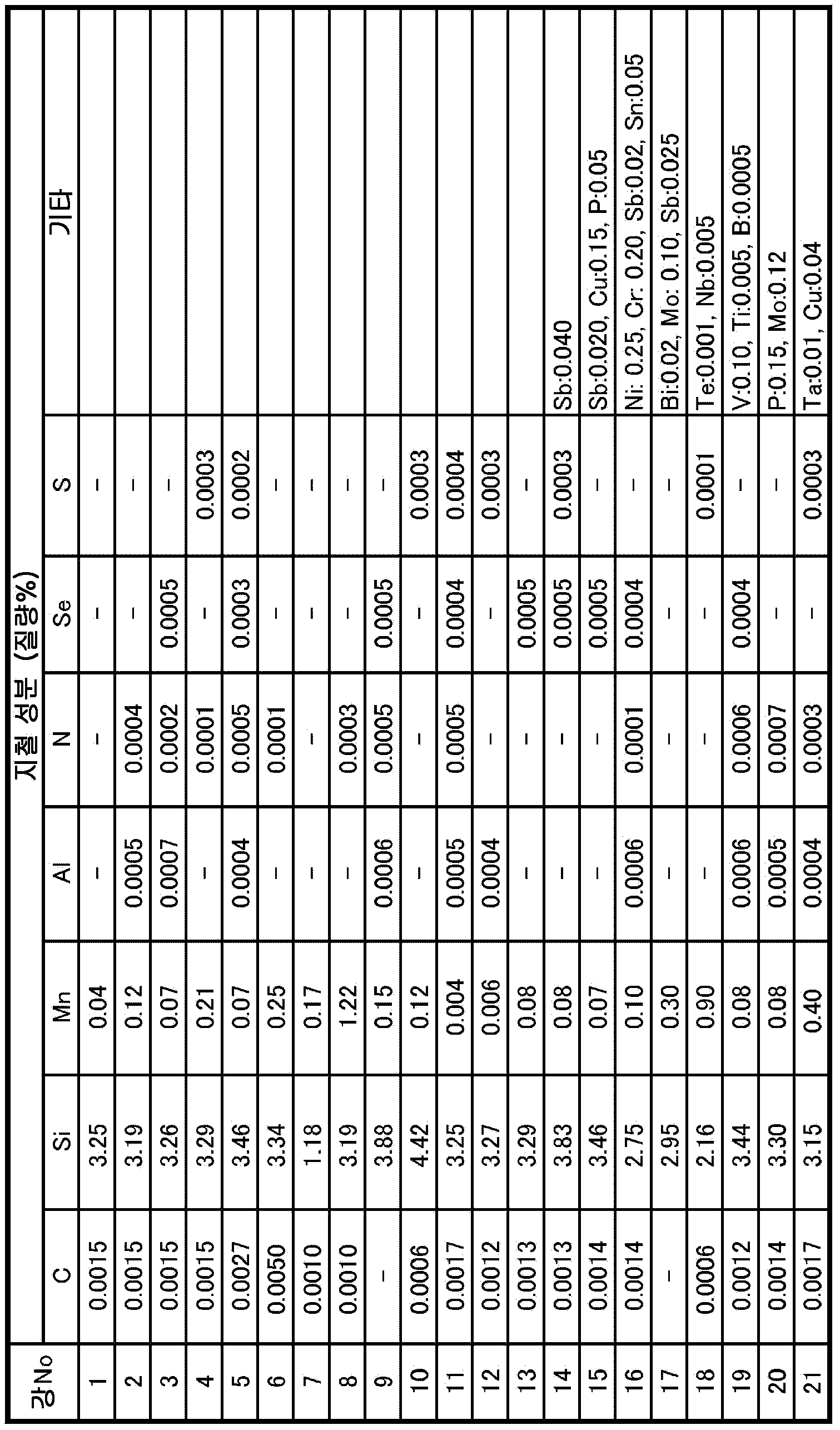
표 2-1 에 기재된 성분 조성을 갖고, 잔부가 Fe 및 불가피적 불순물로 이루어지는 강 슬래브를 연속 주조법으로 제조하고, 1380 ℃ 의 온도로 가열한 후, 열간 압연하여 판두께 2.0 ㎜ 의 열연판으로 하고, 1030 ℃ × 10 초의 열연판 어닐링을 실시한 후, 냉간 압연하여 최종 판두께가 0.20 ㎜ 인 냉연판으로 마무리하였다. 그 후, 탈탄 어닐링을 실시하였다. 탈탄 어닐링은, 50 vol% H2 ― 50 vol% N2, 이슬점 55 ℃ 의 습윤 분위기 하에서 840 ℃ × 100 초 유지하였다. 이어서, (A) MgO 의 r0.6 = 65 %, 점도 (100 rpm 임펠러 30 분 교반 후) 30 cP 의 MgO 를 주성분으로 하고, TiO2 를 10 % 첨가한 어닐링 분리제 슬러리 또는, (B) MgO 의 r0.6 = 65 %, 점도 (100 rpm 임펠러 30 분 교반 후) 50 cP 의 MgO 를 주성분으로 하고, TiO2 를 10 % 첨가한 어닐링 분리제 슬러리, (C) MgO 의 r0.6 = 40 %, 점도 (100 rpm 임펠러 30 분 교반 후) 50 cP 의 MgO 를 주성분으로 하고, TiO2 를 10 % 첨가한 어닐링 분리제 슬러리의 3 종의 슬러리를 각각의 재료에 도포하였다. 이어서 최종 마무리 어닐링을 실시하고 나서, 미반응의 어닐링 분리제의 제거 후, 선상의 돌기가 형성된 롤로 가압함으로써 선상의 홈 (간격 4 ㎜, 깊이 : 판두께의 9 %, 압연 직교 방향과의 각도 5°) 을 형성하고 나서, 인산마그네슘과 콜로이달 실리카를 주성분으로 하는 절연 코팅과 도포·베이킹하는 평탄화 어닐링을 실시하여 제품으로 하였다.A steel slab having the component composition shown in Table 2-1, the balance of which is composed of Fe and inevitable impurities, is produced by a continuous casting method, heated to a temperature of 1380 ° C., and hot rolled to obtain a hot rolled sheet having a thickness of 2.0 mm. After annealing the hot-rolled sheet at 1030 ° C. for 10 seconds, it was cold rolled to finish with a cold-rolled sheet having a final plate thickness of 0.20 mm. Subsequently, decarburization annealing was performed. Decarburization annealing was maintained at 840 ° C. × 100 seconds under a humid atmosphere of 50 vol% H 2 -50 vol% N 2 and a dew point of 55 ° C. Subsequently, (A) MgO r 0.6 = 65%, viscosity (100 rpm impeller 30 minutes after stirring) MgP of 30 cP as the main component, TiO 2 and 10% of annealing separator slurry, or (B) MgO of r 0.6 = 65%, viscosity (after stirring at 100 rpm impeller for 30 minutes) 50 cP of MgO as the main component, annealing separator slurry containing 10% of TiO 2 , (C) r 0.6 = 40% of MgO, viscosity ( After stirring for 30 minutes at 100 rpm impeller) Three types of slurry of an annealing separator slurry in which 50 cP of MgO was used as a main component and TiO 2 was added at 10% were applied to each material. Subsequently, after the final annealing, the unreacted annealing separator is removed, and then pressurized with a roll formed with a linear projection (
상기에서 얻어진 제품으로부터, 폭 30 ㎜ 및 길이 (압연 방향) 280 ㎜ 의 시험편을 잘라내어, 800 ℃ × 2 h, N2 중에서의 응력 제거 어닐링을 실시하고 나서 엡스타인 시험법에 의해 자기 특성을 평가하였다. 또, 압연 방향과 직교하는 방향의 지철 계면을 조사하기 위해, 압연 직교 방향 12 ㎜, 압연 방향 8 ㎜ 의 샘플을 잘라내어, 수지에 매립하고 나서 연마하고, 주사형 전자 현미경으로 압연 직교 방향의 지철 계면을 관찰 (폭 60 ㎛ × 20 시야) 함으로써, 식 (1) 의 존재 빈도 n 의 평균치와 표준 편차를 산출하였다.From the product obtained above, a test piece having a width of 30 mm and a length (rolling direction) of 280 mm was cut out and subjected to stress relief annealing at 800 ° C. × 2 h, N 2 , and then magnetic properties were evaluated by the Epstein test method. Moreover, in order to investigate the iron-iron interface in the direction orthogonal to the rolling direction, samples of 12 mm in the rolling orthogonal direction and 8 mm in the rolling direction were cut out, embedded in a resin, and then polished, and then rolled orthogonally in a rolling orthogonal direction with a scanning electron microscope By observing (60 µm × 20 fields of view), the average value of the frequency n of expression (1) and the standard deviation were calculated.
또, 가열한 수산화나트륨에 의해 절연 장력 코팅을 제거한 후, 표면에 포스테라이트 피막이 부착된 상태의 강판을 화학 분석하는 것에 의해, 강판 표면의 Mg 겉보기 중량 (강판 편면당) 을 측정한 결과, 어느 강판도 강판의 편면당 0.35 ∼ 0.65 g/㎡ 의 범위의 Mg 겉보기 중량이었다.In addition, after removing the insulating tension coating with the heated sodium hydroxide, by chemical analysis of the steel sheet with a forsterite film attached to the surface, as a result of measuring the Mg apparent weight (per side of the steel sheet) of the steel sheet surface, The steel sheet was also Mg apparent weight in the range of 0.35 to 0.65 g /
또, 제품의 절연 코팅 및 포스테라이트 피막을 제거하고 나서, 지철 부분을 화학 분석하여 지철 성분을 확정시켰다. 지철 성분의 분석 결과를 표 2-2 에 나타낸다. 어닐링 분리제 조건의 변경에 상관없이 지철 성분은 동등하였다.In addition, after removing the insulating coating and forsterite coating of the product, the iron component was determined by chemical analysis of the iron component. Table 2-2 shows the analysis results of the iron components. Regardless of the change in the conditions of the annealing separator, the ferrous components were equivalent.
표 3-1, 표 3-2 및 표 3-3 에, 어닐링 분리제 조건 및 각각의 어닐링 분리제 조건에서 얻어진 재료의 자기 특성 (μr15/50, W17/50) 을 기재한다. 표 3-1, 표 3-2 및 표 3-3 에 나타내는 결과에 의하면, 본 발명에 따르는 강판에 있어서 W17/50 : 0.67 W/㎏ 이하가 얻어지고 있다. 특히, n 의 표준 편차가 평균치의 0.3 이하를 만족시키는 강판은 W17/50 : 0.65 W/㎏ 이하의 제품이 안정적으로 얻어지고 있다.In Table 3-1, Table 3-2 and Table 3-3, are shown the magnetic properties of the material obtained in the annealing separating agent condition and each of the annealing separator condition (μr 15/50, W 17/50). According to the results shown in Table 3-1, Table 3-2 and Table 3-3, in the steel sheet according to the present invention, W 17/50 : 0.67 W / kg or less is obtained. Particularly, a product having a standard deviation of n satisfying 0.3 or less of the average value of W 17/50 : 0.65 W / kg or less is stably obtained.
[표 2-1][Table 2-1]

[표 2-2][Table 2-2]
[표 3-1][Table 3-1]

[표 3-2][Table 3-2]

[표 3-3][Table 3-3]

1 : 강판 (지철)
2 : 포스테라이트 피막
20 : 피막 본체
a ∼ e : 피막의 고립 부분 (본 발명에 있어서의 고립되는 부분)1: steel plate (iron)
2: Forsterite film
20: film body
a to e: isolated part of the film (isolated part in the present invention)
Claims (4)
상기 홈은, 평균 깊이가 상기 강판의 두께의 6 % 이상 및 이웃하는 홈 상호간의 거리가 1 ∼ 15 ㎜ 의 범위이고,
주파수 50 Hz 및 최대 자속 밀도 1.5 T 로 교류 자화시켰을 때의 비투자율 μr15/50 이 35000 이상이고,
상기 강판의 압연 방향과 직교하는 단면의, 상기 강판과 상기 피막의 계면에 있어서 상기 피막의 연속 부분으로부터 이간되어 고립되는 부분의 존재 빈도가 0.3 개/㎛ 이하인 방향성 전기 강판.On the front and rear surfaces of the steel sheet, a coating having a forsterite of 0.2 g / m 2 or more as a main component with an Mg apparent weight, and the surface of the steel sheet has an angle of 45 ° or less with the direction perpendicular to the rolling direction and the rolling direction. A grain-oriented electrical steel sheet having a plurality of grooves extending linearly in a transverse direction and arranged at intervals in a rolling direction,
The groove has an average depth of 6% or more of the thickness of the steel plate and a distance between neighboring grooves in a range of 1 to 15 mm,
The specific magnetic permeability μr 15/50 when alternating magnetization at a frequency of 50 Hz and a maximum magnetic flux density of 1.5 T is 35000 or more,
A grain-oriented electrical steel sheet having a cross-section orthogonal to the rolling direction of the steel sheet, and a frequency of presence of an isolated part separated from the continuous part of the film at an interface between the steel sheet and the film is 0.3 pcs / µm or less.
상기 고립되는 부분의 존재 빈도가 0.1 개/㎛ 이하인 방향성 전기 강판.According to claim 1,
The grain-oriented electrical steel sheet in which the frequency of the isolated parts is 0.1 or less / µm.
상기 고립되는 부분의 존재 빈도의 압연 방향과 직교하는 방향의 분포에 있어서의 표준 편차가 평균치의 30 % 이하인 방향성 전기 강판.The method of claim 1 or 2,
The grain-oriented electrical steel sheet in which the standard deviation in the distribution in the direction perpendicular to the rolling direction of the frequency of existence of the isolated portion is 30% or less of the average value.
상기 홈의 평균 깊이가 상기 강판의 두께의 13 % 이상인 방향성 전기 강판.The method according to any one of claims 1 to 3,
A grain-oriented electrical steel sheet having an average depth of the grooves of 13% or more of the thickness of the steel sheet.
Applications Claiming Priority (3)
| Application Number | Priority Date | Filing Date | Title |
|---|---|---|---|
| JPJP-P-2017-188734 | 2017-09-28 | ||
| JP2017188734 | 2017-09-28 | ||
| PCT/JP2018/035495 WO2019065645A1 (en) | 2017-09-28 | 2018-09-25 | Grain-oriented electrical steel sheet |
Publications (2)
| Publication Number | Publication Date |
|---|---|
| KR20200043440A true KR20200043440A (en) | 2020-04-27 |
| KR102407899B1 KR102407899B1 (en) | 2022-06-10 |
Family
ID=65902956
Family Applications (1)
| Application Number | Title | Priority Date | Filing Date |
|---|---|---|---|
| KR1020207008121A KR102407899B1 (en) | 2017-09-28 | 2018-09-25 | grain-oriented electrical steel sheet |
Country Status (8)
| Country | Link |
|---|---|
| US (1) | US11198916B2 (en) |
| EP (1) | EP3690067B1 (en) |
| JP (1) | JP6856114B2 (en) |
| KR (1) | KR102407899B1 (en) |
| CN (1) | CN111133118B (en) |
| CA (1) | CA3075609C (en) |
| MX (1) | MX2020003640A (en) |
| WO (1) | WO2019065645A1 (en) |
Families Citing this family (3)
| Publication number | Priority date | Publication date | Assignee | Title |
|---|---|---|---|---|
| KR102174155B1 (en) * | 2018-09-27 | 2020-11-04 | 주식회사 포스코 | Annealing separating agent composition for grain oriented electrical steel sheet, grain oriented electrical steel sheet, and method for manufacturing grain oriented electrical steel sheet |
| KR102133909B1 (en) * | 2018-12-19 | 2020-07-14 | 주식회사 포스코 | Grain oriented electrical steel sheet and method for manufacturing the same |
| EP4155423A4 (en) * | 2020-05-19 | 2023-10-11 | JFE Steel Corporation | Grain-oriented electromagnetic steel sheet and method for manufacturing same |
Citations (8)
| Publication number | Priority date | Publication date | Assignee | Title |
|---|---|---|---|---|
| JPH05202450A (en) | 1992-01-27 | 1993-08-10 | Nippon Steel Corp | Super low iron loss grain-oriented magnetic steel sheet and its manufacture |
| JPH06158166A (en) | 1992-11-17 | 1994-06-07 | Nippon Steel Corp | Grain-oriented silicon steel sheet having extremely low core loss and its production |
| JPH06200325A (en) * | 1992-12-28 | 1994-07-19 | Nippon Steel Corp | Production of silicon steel sheet having high magnetism |
| JP2004162112A (en) * | 2002-11-12 | 2004-06-10 | Jfe Steel Kk | Method for producing grain-oriented magnetic steel sheet excellent in magnetic and coating characteristics and annealing separating agent used for the method |
| JP2011099155A (en) * | 2009-11-09 | 2011-05-19 | Nippon Steel Corp | Thin grain oriented electrical steel sheet, and insulating film-covered thin grain oriented electrical steel sheet |
| JP2012126973A (en) * | 2010-12-16 | 2012-07-05 | Jfe Steel Corp | Grain-oriented electromagnetic steel sheet, and method for manufacturing the same |
| JP2013510239A (en) | 2009-12-04 | 2013-03-21 | ポスコ | Oriented electrical steel sheet with low iron loss and high magnetic flux density |
| KR20140135833A (en) * | 2012-04-26 | 2014-11-26 | 제이에프이 스틸 가부시키가이샤 | Grain-oriented electrical steel sheet and method for manufacturing same |
Family Cites Families (15)
| Publication number | Priority date | Publication date | Assignee | Title |
|---|---|---|---|---|
| DE3473679D1 (en) | 1983-10-27 | 1988-09-29 | Kawasaki Steel Co | Grain-oriented silicon steel sheet having a low iron loss free from deterioration due to stress-relief annealing and a method of producing the same |
| US5173129A (en) * | 1983-10-27 | 1992-12-22 | Kawasaki Steel Corporation | Grain-oriented silicon steel sheet having a low iron loss free from deterioration due to stress-relief annealing and a method of producing the same |
| JPH06220541A (en) | 1993-01-27 | 1994-08-09 | Nippon Steel Corp | High magnetic flux density grain-oriented silicon steel sheet excellent in magnetic core loss and its production |
| DE69840740D1 (en) | 1997-04-16 | 2009-05-28 | Nippon Steel Corp | UNIDIRECTIONAL ELECTROMAGNETIC STEEL PLATE WITH OUTSTANDING FILM AND MAGNETIC PROPERTIES, METHOD OF PRODUCTION AND COOLING CONDITIONING THEREFOR |
| EP0892072B1 (en) | 1997-07-17 | 2003-01-22 | Kawasaki Steel Corporation | Grain-oriented electrical steel sheet excellent in magnetic characteristics and production process for same |
| JP3397293B2 (en) * | 1998-02-17 | 2003-04-14 | 新日本製鐵株式会社 | Manufacturing method of ultra high magnetic flux density unidirectional electrical steel sheet |
| US6309473B1 (en) | 1998-10-09 | 2001-10-30 | Kawasaki Steel Corporation | Method of making grain-oriented magnetic steel sheet having low iron loss |
| JP2002194445A (en) * | 2000-12-27 | 2002-07-10 | Kawasaki Steel Corp | Method for manufacturing grain-oriented electrical steel sheet having high magnetic flux density and excellent film characteristic |
| JP5853352B2 (en) * | 2010-08-06 | 2016-02-09 | Jfeスチール株式会社 | Oriented electrical steel sheet and manufacturing method thereof |
| JP5754097B2 (en) * | 2010-08-06 | 2015-07-22 | Jfeスチール株式会社 | Oriented electrical steel sheet and manufacturing method thereof |
| KR101309346B1 (en) | 2010-08-06 | 2013-09-17 | 제이에프이 스틸 가부시키가이샤 | Grain oriented electrical steel sheet and method for manufacturing the same |
| WO2012032792A1 (en) * | 2010-09-10 | 2012-03-15 | Jfeスチール株式会社 | Grain-oriented magnetic steel sheet and process for producing same |
| CN104024455B (en) * | 2011-12-28 | 2016-05-25 | 杰富意钢铁株式会社 | Grain-oriented magnetic steel sheet and iron loss improvement method thereof |
| US10629346B2 (en) | 2012-04-26 | 2020-04-21 | Jfe Steel Corporation | Method of manufacturing grain-oriented electrical steel sheet |
| WO2016105053A1 (en) | 2014-12-24 | 2016-06-30 | 주식회사 포스코 | Grain-oriented electrical steel plate and production method therefor |
-
2018
- 2018-09-25 EP EP18862120.5A patent/EP3690067B1/en active Active
- 2018-09-25 JP JP2019500613A patent/JP6856114B2/en active Active
- 2018-09-25 WO PCT/JP2018/035495 patent/WO2019065645A1/en unknown
- 2018-09-25 CN CN201880062714.1A patent/CN111133118B/en active Active
- 2018-09-25 MX MX2020003640A patent/MX2020003640A/en unknown
- 2018-09-25 CA CA3075609A patent/CA3075609C/en active Active
- 2018-09-25 KR KR1020207008121A patent/KR102407899B1/en active IP Right Grant
- 2018-09-25 US US16/648,663 patent/US11198916B2/en active Active
Patent Citations (8)
| Publication number | Priority date | Publication date | Assignee | Title |
|---|---|---|---|---|
| JPH05202450A (en) | 1992-01-27 | 1993-08-10 | Nippon Steel Corp | Super low iron loss grain-oriented magnetic steel sheet and its manufacture |
| JPH06158166A (en) | 1992-11-17 | 1994-06-07 | Nippon Steel Corp | Grain-oriented silicon steel sheet having extremely low core loss and its production |
| JPH06200325A (en) * | 1992-12-28 | 1994-07-19 | Nippon Steel Corp | Production of silicon steel sheet having high magnetism |
| JP2004162112A (en) * | 2002-11-12 | 2004-06-10 | Jfe Steel Kk | Method for producing grain-oriented magnetic steel sheet excellent in magnetic and coating characteristics and annealing separating agent used for the method |
| JP2011099155A (en) * | 2009-11-09 | 2011-05-19 | Nippon Steel Corp | Thin grain oriented electrical steel sheet, and insulating film-covered thin grain oriented electrical steel sheet |
| JP2013510239A (en) | 2009-12-04 | 2013-03-21 | ポスコ | Oriented electrical steel sheet with low iron loss and high magnetic flux density |
| JP2012126973A (en) * | 2010-12-16 | 2012-07-05 | Jfe Steel Corp | Grain-oriented electromagnetic steel sheet, and method for manufacturing the same |
| KR20140135833A (en) * | 2012-04-26 | 2014-11-26 | 제이에프이 스틸 가부시키가이샤 | Grain-oriented electrical steel sheet and method for manufacturing same |
Also Published As
| Publication number | Publication date |
|---|---|
| CA3075609C (en) | 2022-06-21 |
| JPWO2019065645A1 (en) | 2019-11-14 |
| WO2019065645A1 (en) | 2019-04-04 |
| JP6856114B2 (en) | 2021-04-07 |
| EP3690067A4 (en) | 2020-08-05 |
| US20200283863A1 (en) | 2020-09-10 |
| MX2020003640A (en) | 2020-07-29 |
| CN111133118B (en) | 2021-10-12 |
| KR102407899B1 (en) | 2022-06-10 |
| CA3075609A1 (en) | 2019-04-04 |
| EP3690067B1 (en) | 2024-04-24 |
| EP3690067A1 (en) | 2020-08-05 |
| US11198916B2 (en) | 2021-12-14 |
| CN111133118A (en) | 2020-05-08 |
Similar Documents
| Publication | Publication Date | Title |
|---|---|---|
| JP5754097B2 (en) | Oriented electrical steel sheet and manufacturing method thereof | |
| KR101421387B1 (en) | Grain oriented electrical steel sheet and method for manufacturing the same | |
| KR101309346B1 (en) | Grain oriented electrical steel sheet and method for manufacturing the same | |
| KR101421388B1 (en) | Grain oriented electrical steel sheet and method for manufacturing the same | |
| KR101593346B1 (en) | Grain-oriented electrical steel sheet and manufacturing method thereof | |
| JP5077470B2 (en) | Oriented electrical steel sheet | |
| KR20170043658A (en) | Low-core-loss grain-oriented electromagnetic steel sheet and method for manufacturing same | |
| KR101683693B1 (en) | Method for producing grain-oriented electrical steel sheet | |
| KR101907768B1 (en) | Low magnetorestriction oriented electromagnetic steel sheet with low iron loss | |
| JP5742294B2 (en) | Method for producing grain-oriented electrical steel sheet | |
| WO2012001952A1 (en) | Oriented electromagnetic steel plate and production method for same | |
| KR102407899B1 (en) | grain-oriented electrical steel sheet | |
| CN110300808B (en) | Grain-oriented electromagnetic steel sheet | |
| JP4192399B2 (en) | Oriented electrical steel sheet and manufacturing method thereof | |
| JP5845848B2 (en) | Method for producing grain-oriented electrical steel sheet | |
| JP6947248B1 (en) | Directional electrical steel sheet | |
| JP5754170B2 (en) | Method for producing grain-oriented electrical steel sheet | |
| JP6879439B1 (en) | Directional electrical steel sheet | |
| JP2020158882A (en) | Grain-oriented electrical steel sheet and method for manufacturing same |
Legal Events
| Date | Code | Title | Description |
|---|---|---|---|
| E902 | Notification of reason for refusal | ||
| E701 | Decision to grant or registration of patent right | ||
| GRNT | Written decision to grant |