KR20200039582A - Improved apparatus for handling metal sheets and operation method thereof - Google Patents
Improved apparatus for handling metal sheets and operation method thereof Download PDFInfo
- Publication number
- KR20200039582A KR20200039582A KR1020190122041A KR20190122041A KR20200039582A KR 20200039582 A KR20200039582 A KR 20200039582A KR 1020190122041 A KR1020190122041 A KR 1020190122041A KR 20190122041 A KR20190122041 A KR 20190122041A KR 20200039582 A KR20200039582 A KR 20200039582A
- Authority
- KR
- South Korea
- Prior art keywords
- sheet
- seat
- horizontal
- electromagnetic beam
- transmitting
- Prior art date
Links
Images


Classifications
-
- B—PERFORMING OPERATIONS; TRANSPORTING
- B23—MACHINE TOOLS; METAL-WORKING NOT OTHERWISE PROVIDED FOR
- B23K—SOLDERING OR UNSOLDERING; WELDING; CLADDING OR PLATING BY SOLDERING OR WELDING; CUTTING BY APPLYING HEAT LOCALLY, e.g. FLAME CUTTING; WORKING BY LASER BEAM
- B23K26/00—Working by laser beam, e.g. welding, cutting or boring
- B23K26/36—Removing material
- B23K26/38—Removing material by boring or cutting
-
- B—PERFORMING OPERATIONS; TRANSPORTING
- B21—MECHANICAL METAL-WORKING WITHOUT ESSENTIALLY REMOVING MATERIAL; PUNCHING METAL
- B21D—WORKING OR PROCESSING OF SHEET METAL OR METAL TUBES, RODS OR PROFILES WITHOUT ESSENTIALLY REMOVING MATERIAL; PUNCHING METAL
- B21D43/00—Feeding, positioning or storing devices combined with, or arranged in, or specially adapted for use in connection with, apparatus for working or processing sheet metal, metal tubes or metal profiles; Associations therewith of cutting devices
- B21D43/003—Positioning devices
-
- B—PERFORMING OPERATIONS; TRANSPORTING
- B21—MECHANICAL METAL-WORKING WITHOUT ESSENTIALLY REMOVING MATERIAL; PUNCHING METAL
- B21D—WORKING OR PROCESSING OF SHEET METAL OR METAL TUBES, RODS OR PROFILES WITHOUT ESSENTIALLY REMOVING MATERIAL; PUNCHING METAL
- B21D43/00—Feeding, positioning or storing devices combined with, or arranged in, or specially adapted for use in connection with, apparatus for working or processing sheet metal, metal tubes or metal profiles; Associations therewith of cutting devices
- B21D43/02—Advancing work in relation to the stroke of the die or tool
- B21D43/025—Fault detection, e.g. misfeed detection
-
- B—PERFORMING OPERATIONS; TRANSPORTING
- B65—CONVEYING; PACKING; STORING; HANDLING THIN OR FILAMENTARY MATERIAL
- B65G—TRANSPORT OR STORAGE DEVICES, e.g. CONVEYORS FOR LOADING OR TIPPING, SHOP CONVEYOR SYSTEMS OR PNEUMATIC TUBE CONVEYORS
- B65G47/00—Article or material-handling devices associated with conveyors; Methods employing such devices
- B65G47/74—Feeding, transfer, or discharging devices of particular kinds or types
- B65G47/90—Devices for picking-up and depositing articles or materials
- B65G47/92—Devices for picking-up and depositing articles or materials incorporating electrostatic or magnetic grippers
-
- B—PERFORMING OPERATIONS; TRANSPORTING
- B21—MECHANICAL METAL-WORKING WITHOUT ESSENTIALLY REMOVING MATERIAL; PUNCHING METAL
- B21D—WORKING OR PROCESSING OF SHEET METAL OR METAL TUBES, RODS OR PROFILES WITHOUT ESSENTIALLY REMOVING MATERIAL; PUNCHING METAL
- B21D43/00—Feeding, positioning or storing devices combined with, or arranged in, or specially adapted for use in connection with, apparatus for working or processing sheet metal, metal tubes or metal profiles; Associations therewith of cutting devices
- B21D43/20—Storage arrangements; Piling or unpiling
-
- B—PERFORMING OPERATIONS; TRANSPORTING
- B21—MECHANICAL METAL-WORKING WITHOUT ESSENTIALLY REMOVING MATERIAL; PUNCHING METAL
- B21D—WORKING OR PROCESSING OF SHEET METAL OR METAL TUBES, RODS OR PROFILES WITHOUT ESSENTIALLY REMOVING MATERIAL; PUNCHING METAL
- B21D43/00—Feeding, positioning or storing devices combined with, or arranged in, or specially adapted for use in connection with, apparatus for working or processing sheet metal, metal tubes or metal profiles; Associations therewith of cutting devices
- B21D43/28—Associations of cutting devices therewith
- B21D43/287—Devices for handling sheet or strip material
-
- B—PERFORMING OPERATIONS; TRANSPORTING
- B23—MACHINE TOOLS; METAL-WORKING NOT OTHERWISE PROVIDED FOR
- B23K—SOLDERING OR UNSOLDERING; WELDING; CLADDING OR PLATING BY SOLDERING OR WELDING; CUTTING BY APPLYING HEAT LOCALLY, e.g. FLAME CUTTING; WORKING BY LASER BEAM
- B23K26/00—Working by laser beam, e.g. welding, cutting or boring
- B23K26/70—Auxiliary operations or equipment
- B23K26/702—Auxiliary equipment
-
- B—PERFORMING OPERATIONS; TRANSPORTING
- B65—CONVEYING; PACKING; STORING; HANDLING THIN OR FILAMENTARY MATERIAL
- B65G—TRANSPORT OR STORAGE DEVICES, e.g. CONVEYORS FOR LOADING OR TIPPING, SHOP CONVEYOR SYSTEMS OR PNEUMATIC TUBE CONVEYORS
- B65G47/00—Article or material-handling devices associated with conveyors; Methods employing such devices
- B65G47/74—Feeding, transfer, or discharging devices of particular kinds or types
- B65G47/90—Devices for picking-up and depositing articles or materials
Abstract
Description
본 발명은 금속 시트의 취급을 위한 개선된 장치, 특히 금속 시트 컷팅 센터/스테이션과 협동하는 이러한 장치 및 그 작동 방법에 관한 것이다.The present invention relates to improved devices for the handling of metal sheets, in particular such devices in cooperation with metal sheet cutting centers / stations and methods of operation thereof.
공지된 바와 같이, 금속 시트 가공 및 취급에 있어서, 하나의 워크 스테이션과 다른 워크 스테이션 사이에서 금속 시트를 이송 및 취급할 필요성이 존재한다.특히, 금속 시트는 저장된 스택으로부터 취출된 후, 다양한 종류의 암을 취급함으로써 원하는 위치로 이송된다.As is known in the art of metal sheet processing and handling, there is a need to transport and handle metal sheets between one work station and another work station. Particularly, after the metal sheets are taken out from a stored stack, various kinds of It is transported to the desired position by handling the arm.
특히 효과적인 취급 시스템은 WO2008/139409에 동일한 출원인의 이름으로 기재된 시스템이며, 이는 본원에 참조로서 포함된다.A particularly effective handling system is the system described in the name of the same applicant in WO2008 / 139409, which is incorporated herein by reference.
금속 시트는 일반적으로 다소 얇고(예를 들면, 0.5∼25㎜) 길지만(예를 들면, 1500×3000㎜) 다소 무겁기 때문에, 금속 시트 부분이 제공된 자세를 벗어나서 이송되는 동안에 장비와 충돌하게 되는 일 없이, 핸들링 암에 의해 원하는 자세(전형적으로 수평)로 정확하게 유지되도록 보장될 필요가 있다.Metal sheets are generally rather thin (e.g. 0.5-25 mm) and long (e.g. 1500 x 3000 mm), but rather heavy, so that the metal sheet portion does not collide with the equipment while being transported outside the provided posture. , It needs to be ensured that it is precisely maintained in the desired posture (typically horizontal) by the handling arm.
이러한 관점에서 특히 중요한 조건은 컷팅 스테이션을 위한 취급 장치(정확하게는 WO2008/139409에 기재된 것)에서 발생한다. 사실상, 컷팅 스테이션에 있어서, 시트는 매우 복잡한 둘레를 갖는 복수의 성형 피스로 컷팅된다. 또한, 컷팅은 시트 재료의 조성에 기초하여 다양한 기술로 행해진다: 예를 들면, 레이저 컷팅, 산소 랜스 컷팅, 워터젯 컷팅, 플라즈마 컷팅 등을 채용하는 기계가 존재한다. 컷팅이 완료되면, 취급 시스템은 한편으로는 각각의 맞춤형 컷팅을 행하고, 성형 피스를 취출하여 전용 저장 장소 또는 추가의 가공 및 조립 스테이션으로 운반하고, 다른 한편으로는 각각의 컷팅 피스를 제거한 후 남은 잔여 시트 폐기물인 스크랩을 수집하여 수집 지점으로 이송시켜야 한다.A particularly important condition in this respect arises in the handling device for the cutting station (exactly described in WO2008 / 139409). In fact, in a cutting station, the sheet is cut into a plurality of forming pieces with very complex perimeters. Further, cutting is performed by various techniques based on the composition of the sheet material: for example, there are machines employing laser cutting, oxygen lance cutting, water jet cutting, plasma cutting, and the like. When the cutting is complete, the handling system performs each customized cutting on the one hand, takes out the molded piece and transports it to a dedicated storage or additional processing and assembly station, and on the other hand, the residual remaining after removing each cutting piece. Sheet waste scrap must be collected and transported to the collection point.
이러한 상황 하에서, 맞춤형 컷팅된 성형 피스가, 예를 들면 불충분하게 깊은 컷팅 또는 기하학적 구속으로 인해 잔여 스크랩 재료에 부분적으로 결합된 상태로 남아있을 수 있기 때문에 가장 중요한 단점이 발생한다.Under these circumstances, the most important disadvantage arises because custom cut molded pieces may remain partially bound to the remaining scrap material, for example due to insufficiently deep cutting or geometric constraints.
또한, 레이저 컷팅 헤드가 사용될 때에, 하부 지지 메시에 피스의 바람직하지 않은 결합점이 발생하여 유사한 결점을 야기할 수 있다.Also, when a laser cutting head is used, undesirable bond points of the piece to the lower support mesh may occur, causing similar defects.
따라서, 일단 핸들러에 의해 성형 피스를 포획하고 들어올리면, 취급 사이클에서 걸림이 발생할 수 있다. 첨부된 도 1로부터, 금속 시트로부터 피스 컷인을 들어올리는 핸들러의 상세한 투시도를 나타내고, 컷팅 피스와 그 금속 시트 스크랩 사이의 잔류 결합(오른쪽 원으로 식별됨)으로 인해 가능한 이상이 발견될 수 있다.Therefore, once the molded piece is captured and lifted by the handler, a jam may occur in the handling cycle. From the accompanying FIG. 1, a detailed perspective view of a handler lifting a piece cut-in from a metal sheet is shown, and possible anomalies can be found due to residual bonds (identified by the right circle) between the cutting piece and its metal sheet scrap.
이러한 조건 하에서 컷팅 피스 파지 및 인출의 작업 주기가 계속되는 경우, 컷팅 피스에 속하지 않은 금속 시트의 부분의 원치않는 드래깅 및 리프팅이 발생하여 간섭 또는 오작동 문제를 일으킬 수 있어 결함 감지 가능성이 있으며, 작동 주기가 중단되고, 작업자의 필수 개입이 요구된다.If the working cycle of gripping and pulling out of the cutting piece continues under these conditions, unwanted dragging and lifting of parts of the metal sheet not belonging to the cutting piece may occur, which may cause interference or malfunction problems, which may lead to defect detection. Interrupted and required operator intervention required.
이러한 결점을 회피하기 위해, 종래 기술에 따르면 성형 피스 또는 금속 시트 스크랩의 불규칙한 자세를 검지할 때에 "수동 행동 경고" 신호를 생성하는 광학 검지 시스템을 사용하는 것이 이미 제안되어 있다.To avoid this drawback, it has already been proposed according to the prior art to use an optical detection system that generates a "passive action warning" signal when detecting the irregular posture of a forming piece or metal sheet scrap.
전형적으로, 리프팅은 항상 수평면 상에 유지된 금속 시트에 의해 발생하기 때문에, 취급 장치의 작업 영역을 스위핑하도록 지지대 상에 회전식으로 장착된 수평으로 스위핑된 광원에 의해 생성된 수평 광선을 설치하는 것이 제공된다.Typically, lifting is always caused by a sheet of metal held on a horizontal surface, so it is provided to install a horizontal beam generated by a horizontally swept light source that is rotatably mounted on a support to sweep the working area of the handling device. do.
금속 시트는 매우 얇기 때문에 수평면 상에 잔존하면 회전 광선에 영향을 미치지 않는다. 픽업 단계에 있어서, 일부 오작동으로 인해 금속 시트의 일부가 수평면에 대하여 기울어지면, 금속 표면에 의해 반사되고, 적합한 광학 센서에 의해 감지되는 광선에 부딪친다. 광학 검지 시스템이 광학 빔의 반사 상황을 결정할 때에, 취급 장치에 결함이 발생하기 전에 신속하게 작용하도록 기계 사이클의 제어 로직에 작용하는 경고 신호를 발생시킨다.The metal sheet is very thin, so if it remains on a horizontal surface, it does not affect the rotating beam. In the pick-up step, if a portion of the metal sheet is tilted with respect to the horizontal plane due to some malfunction, it is reflected by the metal surface and strikes a light beam sensed by a suitable optical sensor. When the optical detection system determines the reflection condition of the optical beam, it generates a warning signal that acts on the control logic of the machine cycle to act quickly before a defect occurs in the handling device.
그러나, 공지된 광학 검지 시스템은 완전히 신뢰할만한 것으로 입증되지 않았다. 특히, 금속 시트가 매우 얇은 경우, 금속 시트 구성요소가 인출 평면에서 불규칙하게 매달려 있는 경우라도, 광선이 반사되지 않는 조건이 발생할 수 있다.However, known optical detection systems have not been proven to be completely reliable. In particular, when the metal sheet is very thin, a condition in which light rays are not reflected may occur even when the metal sheet components are irregularly suspended in the drawing plane.
종래 기술은 반드시 회전형일 필요는 없는 다른 유형의 검지 광선을 제공한다. 예를 들면, EP1222975는 가공되는 워크피스의 위치 검지 시스템을 개시하고, 여기서는 가공되는 피스의 정확한 위치를 검지하도록 구성된 제한된 작업 영역으로 수렴하는 복수의 광선이 제공된다. 그러나, 이 구성은 가공되는 피스의 정확한 위치를 결정하기 위해 중요한 제한된 작업 영역에 적용하기에 적합하지만, 컷팅 스테이션에 있어서 시트의 전체 영역(수 평방 미터의 크기)에 사용되는 경우, 비용이 들 수 있다.The prior art provides another type of detection light, which need not be rotatable. For example, EP1222975 discloses a position detection system for a workpiece to be machined, wherein a plurality of rays are provided converging to a limited working area configured to detect the exact location of the machined workpiece. However, this configuration is suitable for applications in limited working areas that are important for determining the exact position of the piece being machined, but it can be costly when used for the entire area of the sheet (several square meters in size) in a cutting station. have.
따라서, 본 발명의 기초가 되는 문제는 취급 장치 상에 금속 시트를 픽업 및 이송하는 동작 단계에서 이상을 검지하는 문제에 대해 간단하고 경제적인 해결책을 제공하는 장치를 제공하고, 특히 종래 기술의 해결책과 관련하여 더 우수하고 보다 안정적인 동작을 갖는 검지 장치를 제공할 필요가 있다.Therefore, the problem underlying the present invention provides an apparatus that provides a simple and economical solution to the problem of detecting anomalies in the operation step of picking up and conveying a metal sheet on a handling device, and in particular with prior art solutions. In this regard, there is a need to provide a detection device having better and more stable operation.
이 해결책은 여기에 포함된 주요 청구항에 언급된 특징을 갖는 장치 및 방법을 통해 얻어진다. 종속항들은 본 발명의 바람직한 특징을 개시한다.This solution is obtained through an apparatus and method having the features mentioned in the main claims contained herein. The dependent claims disclose preferred features of the invention.
그러나, 본 발명의 다른 특징 및 이점은 순전히 비제한적인 예로서 제공되고, 첨부 도면에 도시된 바람직한 실시예에 대한 이하의 상세한 설명으로부터 보다 명백해질 것이다.However, other features and advantages of the present invention are provided as purely non-limiting examples, and will become more apparent from the following detailed description of the preferred embodiment shown in the accompanying drawings.
도 1은 이미 예상된 바와 같이, 예시적인 컷인 금속 시트의 리프팅시의 핸들러 디테일의 확대 사시도에 관한 것이다.
도 2는 컷팅 스테이션에 근접하여 장착된 본 발명의 장치의 전체 사시도이다.
도 3은 도 2의 장치의 개략적인 입면 측면도이다.
도 4는 도 3의 장치의 확대 부분의 개략적인 입면 측면도이다.
도 5는 스크랩 제거 포크를 갖는 도 2의 도면과 유사한 도면이다.
도 6은 도 1의 장치의 입면 정면도이다.
도 7은 본 발명에 따른 검지 빔 패턴의 평면도이다.1 relates to an enlarged perspective view of handler details upon lifting of an exemplary cut-in metal sheet, as already anticipated.
2 is an overall perspective view of the device of the present invention mounted close to a cutting station.
3 is a schematic elevational side view of the device of FIG. 2;
4 is a schematic elevational side view of an enlarged portion of the device of FIG. 3;
5 is a view similar to that of FIG. 2 with a scrap removal fork.
6 is a front elevational view of the device of FIG. 1.
7 is a plan view of the detection beam pattern according to the present invention.
도 1의 개략도로부터 알 수 있는 바와 같이, 금속 시트 컷팅 스테이션은 전형적으로 컷팅 장비(예를 들면, 이동 가능한 프레임 및 제어 로직을 갖는 레이저 빔 헤드)를 둘러싸는 캐비닛(1a)에 근접하여 휴지 베드 또는 시트 교환 지지대(1)를 포함한다.As can be seen from the schematic of FIG. 1, the metal sheet cutting station typically rests on the
시트 변경 지지대(1)는 전형적으로, 예를 들면 평행 스트립으로 구성된 휴지 메시(resting mesh)를 포함하고, 그 위에 컷팅해야 할 금속 시트(2)가 놓여지고, 이어서 컷팅 스테이션의 제어 로직에서 미리 설정된 프로그램에 따라 컷팅된다. 이러한 목적으로, 시트 변경 지지대(1)는 캐비닛(1a) 내에서 이동하거나 정지 상태로 유지되고, 이에 대해 컷팅 헤드가 이동된다.The
금속 시트(2)가 다양한 형상의 피스 및 스크랩으로 분할되고 완성될 때에 모두 시트 교환 지지부(1)와의 취급은 적절한 취급 장치를 통해 달성된다. 이러한 장치는 그 자체로 공지된 이송 핸들러, 예를 들면 흡입 또는 자기 픽업 유닛(3a)이 제공된 파지 헤드(3)를 사용한다.When the
이 공지된 배열에 있어서, 제 1 단계에 있어서의 파지 헤드(3)는 금속 시트의 스택으로부터 금속 시트(2)를 매번 파지하고, 이를 수평면 상에 유지하여 컷팅 스테이션의 변경 지지대(1)의 휴지 메시로 전달한다. 이어서, 일단 금속 시트(2)가 위치되면, 컷팅 수단(도시되지 않음)은 일련의 성형 피스(4, 5)를 규정하기 위해 금속 시트의 컷팅을 행하도록 작동되게 되며, 매우 상이한 프로파일에 따라 측정하도록 컷팅되고, 금속 시트의 나머지 부분으로부터 컷팅되어 스크랩 부품을 구성한다. 추가 단계에 있어서, 파지 헤드(3)는 형상화된 피스(4, 5)를 픽업하고, 이를 저장 위치 또는 후속 처리로 전달하도록 다시 작용한다. 마지막으로, 동일한 파지 헤드 또는 다른 유사한 수단(예를 들면, 도 5에 도시된 바와 같은 파지 헤드에 결합된 다중 갈래 포크)은 또한 금속 시트(2)의 스크랩 부분을 제거하여 폐기 사이클로 보내지도록 작동한다.In this known arrangement, the
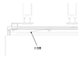
예를 들면, 도 2 및 도 5에는 성형 피스(4, 5)의 제거 후(도 2 및 5에 있어서, 상기 피스(4, 5)가 이미 제거된 금속 시트(2)의 영역(4a 및 5a)만이 도시되어 있음), 파지 헤드(3)가 금속 시트(2)의 잔류 구조체(스크랩) 상으로 복귀되어 도 2에서는 흡입 장치로, 도 5에서는 포크로 인출하고, 폐기 사이클로 이송하는 단계에 있어서의 취급 장치가 도시되어 있다. For example, in FIGS. 2 and 5, after removal of the forming pieces 4 and 5 (in FIGS. 2 and 5,
이미 상술한 바와 같이, 각각의 형상의 피스(4 또는 5)의 제거 단계(도 1) 동안, 및 스크랩 제거(도 2 및 5) 동안에 모두 이동 프로그래밍에서 제어 로직에 의해 제공되는 바와 같이 금속 시트가 완전히 수평으로 유지되지 않지만, 그 소정 부분은 다른 구성요소에 고정된 상태로 유지되거나 임의의 경우에 있어서 아래쪽으로 불규칙하게 매달려 있는 경우가 발생될 수 있다(또한, 스크랩의 얇은 부분이 포크 갈래를 통과하여 아래쪽으로 매달려 있는 도 6 참조). 이들 금속 시트 파지의 요철은 자명한 바와 같이 취급 장치의 작동에 있어서의 결점 및 후속의 제거 동작에 있어서의 문제를 야기할 것이며, 결국 바람직하지 않은 걸림이 발생하여 사이클 정지로 이어질 수 있다.As already described above, the metal sheet is provided as provided by the control logic in the mobile programming both during the removal step (FIG. 1) of each shaped piece 4 or 5 and during scrap removal (FIGS. 2 and 5). Although not completely horizontal, a certain portion may remain fixed to other components, or in some cases, irregularly hanging downward may occur (also, a thin portion of the scrap passes through the fork fork) Figure 6 is hanging downwards). The unevenness of these metal sheet grips, as will be apparent, will cause drawbacks in the operation of the handling device and problems in subsequent removal operations, which may eventually lead to undesired jamming and cycle stoppage.
이러한 불규칙성을 신속하게 검지하고 가능하게는 자동으로 작용시키기 위해, 본 발명에 따르면 정지 교차 전자기 빔과 상대 검지기를 이용하는 수평 배리어로 구성된 검지 시스템이 제공된다.In order to detect this irregularity quickly and possibly act automatically, according to the present invention, a detection system comprising a horizontal barrier using a stationary cross electromagnetic beam and a relative detector is provided.
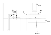
특히, 본 발명에 따르면, 수평 배리어는 컷팅 후에 시트의 피스 및 스크랩이 놓여있는 시트 교환 지지대(1)의 2개의 대향 측면 상에 서로 마주보도록 배열된 송수신 포토다이오드의 적어도 한 쌍의 바(B1 및 B2)에 의해 규정된다. In particular, according to the present invention, the horizontal barrier comprises at least one pair of bars (B1 and a pair of transmitting and receiving photodiodes) arranged to face each other on two opposite sides of the sheet exchange support (1) on which the piece of sheet and scrap are placed after cutting. B2).
포토다이오드의 2개의 수평 바(B1 및 B2), 그리고 이에 따른 전자기 빔의 수평 배리어는 취급 장치의 시트 교환 지지대(1) 상의 금속 시트(2)의 휴지면 바로 위에 동일한 높이로, 예를 들면 상기 휴지면 위의 약 50∼100㎜, 바람직하게는 80㎜의 높이에서 배열된다.The two horizontal bars B1 and B2 of the photodiode, and thus the horizontal barrier of the electromagnetic beam, are at the same height just above the resting surface of the
각각의 바(B1 및 B2)에는 바의 전체 치수에 이르기까지, 제 1 프리셋 피치와 나란히 배열된 복수의 포토다이오드가 제공된다. 중요한 특징에 따르면, 포토다이오드는 각각의 바 상에 배열되어, 바 축에 대하여 상이한 각도를 향하여 배향된 복수의 고정 전자기 빔을 방출하고, 바에 수직인 라인 주위에 소정 폭의 복수의 고정 수평 빔 패턴을 형성한다.Each bar B1 and B2 is provided with a plurality of photodiodes arranged alongside the first preset pitch, up to the overall dimensions of the bar. According to an important feature, a photodiode is arranged on each bar, emitting a plurality of fixed electromagnetic beams oriented toward different angles with respect to the bar axis, and a plurality of fixed horizontal beam patterns of a certain width around a line perpendicular to the bar To form.
바로부터 나오는 전자기 빔의 패턴은 포토다이오드 간의 거리와 패턴 폭에 따라 서로 교차한다. 바람직하게는, 전자기 빔은 수평면 상에 있는 삼각형 팬형 패턴에 따라 방출된다.The pattern of electromagnetic beams from the bar intersects each other according to the distance between the photodiodes and the pattern width. Preferably, the electromagnetic beam is emitted according to a triangular fan-like pattern on a horizontal plane.
바 상의 각각의 포토다이오드 사이의 제 1 피치보다 서로 더 가까운 제 2 피치를 이용하여 전자기 빔의 교차를 결정하는 것은(도 7 참조), 전자기 빔에 의해 형성된 평평한 배리어의 중앙 영역에서 빔 패턴의 공간 해상도를 크게 높일 수 있다. Determining the intersection of the electromagnetic beams using a second pitch closer to each other than the first pitch between each photodiode on the bar (see Fig. 7), the space of the beam pattern in the central region of the flat barrier formed by the electromagnetic beam The resolution can be greatly increased.
바람직한 실시예에 따르면, 각각의 송수신 포토다이오드는 바(B1 및 B2) 상에 2∼8㎜, 바람직하게는 4㎜의 상호 거리(제 1 피치)로 배열되고, 바로부터 소정 거리, 예를 들면 100㎜ 이상의 수평면 상에서 교차하는 전자기 빔의 패턴을 생성하기에 적합하다.According to a preferred embodiment, each transmitting and receiving photodiode is arranged on the bars B1 and B2 at a mutual distance (first pitch) of 2 to 8 mm, preferably 4 mm, and a predetermined distance from the bar, for example It is suitable for generating a pattern of electromagnetic beams intersecting on a horizontal plane of 100 mm or more.
바람직하게는, 도 7에 도시된 바와 같이, 빔은 서로 교차하고, 빔 배리어 평면의 중심 영역에서 빔 교차의 비후를 달성하기 위해 비대칭으로 배향된다.Preferably, as shown in Fig. 7, the beams intersect with each other and are asymmetrically oriented to achieve a thickening of the beam intersection in the central region of the beam barrier plane.
예시적인 포토다이오드는 가시 스펙트럼, 예를 들면 전자기 스펙트럼의 적외선 부분에서 전자기 광선을 방출할 필요가 없다. 포토다이오드는, 예를 들면 860㎚의 파장 및 H 1600=9msec 및 H 2160=11msec에 대한 최대 반응 시간을 가질 수 있다.The exemplary photodiode does not need to emit electromagnetic light in the visible spectrum, for example the infrared portion of the electromagnetic spectrum. The photodiode can have, for example, a wavelength of 860 nm and a maximum reaction time for H 1600 = 9 msec and H 2160 = 11 msec.
포토다이오드는 전력이 공급되고, 바람직하게는 유입 전류에 전위차계가 제공되어, 특정 취급 장치에서 2개의 바(B1 및 B2)가 배열되는 거리에 따라 거리 레이트를 조정할 수 있다.The photodiode is powered, and preferably a potentiometer is provided for the inrush current, so that the distance rate can be adjusted according to the distance in which two bars B1 and B2 are arranged in a specific handling device.
바에 가장 가까운 부분에서 빔 패턴이 교차하지 않기 때문에, 바에 더 가까운 낮은 커버리지 영역이 결정되고, 예를 들면 단부 근처의 처음 300∼500㎜에서 광선 해상도가 감소되고, 이러한 이유로 포토다이오드의 바(B1 및 B2)는 바람직하게는 낮은 커버리지 영역보다 더 먼 거리, 예를 들면 약 500㎜보다 먼 거리에서 취급 장치의 실제 작업 영역 외부에 위치된다.Since the beam pattern does not intersect at the portion closest to the bar, a lower coverage area closer to the bar is determined, for example the light beam resolution is reduced at the first 300-500 mm near the end, and for this reason the bar of the photodiode (B1 and B2) is preferably located outside the actual working area of the handling device at a greater distance than the lower coverage area, eg greater than about 500 mm.
또한, 포토 다이오드의 바(B1 및 B2)의 폭은 가공 영역의 확실하고 완전한 커버리지를 갖도록 처리되는 금속 시트의 폭보다 약 50∼100㎜ 큰 것이 바람직하다.Further, it is preferable that the width of the bars B1 and B2 of the photodiode is about 50 to 100 mm larger than the width of the metal sheet processed to have a reliable and complete coverage of the processing area.
도면에 있어서, 포토다이오드의 2개의 바(B1 및 B2)는 시트 교환 지지대(1)의 길이방향 축을 따라 서로 대향하여 도시되어 있고; 따라서 2개의 바는 금속 시트의 더 짧은 측면에 배열된다. 그러나, 일부 특정 설비에 있어서, 도면에 도시된 것에 대하여 90 °로 배향시키거나, 서로 수직인 포토다이오드 바의 2개의 쌍을 제조하는 것이 바람직하다는 것을 배제하지는 않는다. 이러한 옵션은 포토다이오드 거리 레이트가 6미터를 초과하지 않은 경우라도, 현재 시판되는 장치로 용이하게 구현할 수 있는 일부 응용예에서와 같이 5/6 미터보다 큰 금속 시트 치수를 커버할 수 있게 한다.In the figure, the two bars B1 and B2 of the photodiode are shown facing each other along the longitudinal axis of the
포토다이오드의 크기뿐만 아니라 에미터 및 리시버 위치는 동일한 것 사이의 피치를 결정하는 것에 추가하여 특정 작업 조건 또는 특정 응용에 맞게 조정되는 교차 빔의 메시를 규정하기 위해 선택된다. 임의의 경우에 있어서, 포토다이오드의 각각의 전자기 방사선 빔은 2개의 배리어(B1 또는 B2) 중 어느 하나의 일측면 상의 에미터로부터 팬형 메시를 생성하고, 2개의 배리어(B2 또는 B1) 중 다른 하나의 대향 리시버에 각각 충돌한다.The size of the photodiode, as well as the emitter and receiver positions, are selected to define the mesh of the cross beam that is tailored to the specific working conditions or specific application in addition to determining the pitch between the same. In any case, each electromagnetic radiation beam of the photodiode creates a fan-like mesh from an emitter on either side of either of the two barriers (B1 or B2), and the other of the two barriers (B2 or B1) Collide with each of the opposing receivers.
이물질, 예를 들면 아래쪽으로 매달려 있는 금속 시트 플랩이 방사선 빔을 차단하면, 해당 빔의 방사선이 대상 리시버에 도달하지 않고, 리시버와 충돌하는 방출의 부재는 비정상 동작 상태로서 인식된 신호를 생성하여, 일련의 정정 동작의 개시를 결정한다.When a foreign object, for example, a metal sheet flap hanging downwards blocks the radiation beam, the radiation of the beam does not reach the target receiver, and the absence of the emission colliding with the receiver generates a signal recognized as an abnormal operating state, The start of a series of corrective actions is determined.
교차하는 빔 패턴을 방출하는 포토다이오드 대향 바를 갖는 이러한 특정 배열은 금속 시트 핸들러에 대한 특정 적용을 위한 최적의 검지 해상도를 갖는 도 7에 도시된 것과 유사한 광선의 메시형 배리어를 생성한다. 특히, 감소된 수의 포토다이오드를 사용하면, 두께 0.5㎜ 및 폭 10∼15㎜의 금속 시트 또는 금속 시트의 일부를 차단하기 위한 광선 메시 해상도가 얻어진다.This particular arrangement with photodiode facing bars emitting intersecting beam patterns creates a meshed barrier of light rays similar to that shown in FIG. 7 with optimal detection resolution for specific applications for metal sheet handlers. In particular, the use of a reduced number of photodiodes results in a ray mesh resolution for blocking a metal sheet or part of a metal sheet 0.5 mm thick and 10-15 mm wide.
금속 시트의 얇은 스트립이 특정 위치에서 어떠한 빔도 차단할 수 없는 가장 까다로운 조건을 극복하기 위해, 포토다이오드 바에 의해 검지된 신호의 경시 평가가 이용된다.In order to overcome the most demanding conditions, where a thin strip of metal sheet cannot block any beam at a particular location, a time-based evaluation of the signal detected by the photodiode bar is used.
특히, 검지된 신호는 핸들러(3)의 리프팅 이동 동안에 평가되고, 예를 들면 바(B1 및 B2)로부터의 신호의 획득은, 예를 들면 약 5초 후 또는 높이 0에서 높이 150㎜의 프리셋 후속 순간까지 이동 개시로부터 파지 헤드(3)의 리프팅 단계에서 행해진다.In particular, the detected signal is evaluated during the lifting movement of the
검지된 신호의 획득은 다른 방법으로 행해질 수 있다. 첫번째 방법은 제 1 프리셋 높이(전형적으로 교환 테이블(1)의 휴면 메시 상에 금속 시트가 드로잉된 위치와 관련하여 100-120㎜)로부터 신호의 타임 스캐닝을 제공하여 배리어 신호의 판독이 시작되고, 시간(T)(전형적으로 1∼5초) 후에 종료될 수 있으며; 대신에 제 2 방법은 대신에 배리어 신호의 판독이 그러한 제 1 프리셋 높이로부터 시작하여, 예를 들면 제 1 프리셋 높이 위로 150㎜의 높이 H까지 계속되도록 제공된다.The acquisition of the detected signal can be done in different ways. The first method provides time scanning of the signal from the first preset height (typically 100-120 mm relative to the position where the metal sheet was drawn on the dormant mesh of the exchange table 1) to start reading the barrier signal, Can be terminated after time T (typically 1-5 seconds); Instead, the second method is provided instead so that the reading of the barrier signal starts from such a first preset height and continues to a height H of 150 mm above the first preset height, for example.
이에 의해, 이상 시트 부분이 빔에 의해 차단되지 않는 일부 위치가 존재하더라도, 리프팅 이동 중에 금속 시트의 수평면에 따라 부품을 검지하지 못할 가능성이 급격히 감소된다.By this, even if there are some positions where the abnormal sheet portion is not blocked by the beam, the possibility of failing to detect the part along the horizontal surface of the metal sheet during the lifting movement is drastically reduced.
배리어로부터 나오는 신호는 아날로그적으로 검지될 수 있거나 샘플링되어 디지털적으로 처리될 수 있다.The signal from the barrier can be detected analogly or sampled and processed digitally.
이 시간 또는 이동 간격에서 광선의 수평 배리어가 차단되지 않으면, 제어 시스템에 의해 신호가 검지되지 않아 취급 장치는 작업 사이클을 계속한다.If the horizontal barrier of the light beam is not blocked at this time or travel interval, the signal is not detected by the control system and the handling device continues the work cycle.
대신에, 성형 피스 아래에 매달린 스크랩 재료에 의해 또는 매우 동일한 피스에 의해 광선 배리어가 차단되는 경우, 제어 시스템은 적어도 배리어로부터의 신호, 예를 들면 특정 임계값 이상의 아날로그값을 검지할 수 있고, 제어 로직은, 예를 들면 파지 헤드(3)의 이동 정지를 트리거하고 다시 시작 위치로 갈 수 있는 경고 조건을 결정할 수 있다. 이 경우에 있어서, 파지 및 리프팅 작업은 바람직하게는 3회 반복되는데, 이는 잘못된 차단 신호가 발생하지 않았음을 확인하고, 이동이 반복되면 문제가 해결(예를 들면, 하중이 반복되면 스크랩과 컷팅 피스 사이의 결합 포인트를 파손시키기 때문에)되는지의 여부를 검증하기 위한 것이다. 장치가 광선의 차단을 검지하는 제 3회의 연속적인 시도 후에, 본 발명의 방법은 대안적으로 다음을 제공한다:Instead, if the light barrier is blocked by scrap material hung under the molded piece or by a very identical piece, the control system can detect at least a signal from the barrier, eg an analog value above a certain threshold, and control Logic may, for example, trigger a stoppage of movement of the
A. 걸림 신호를 유발한 특정 컷팅 피스의 픽업을 건너뛰고 이후의 성형 피스를 픽업하는 작업 사이클을 계속한다.A. Skip pickup of the specific cutting piece that caused the jam signal and continue the work cycle to pick up the subsequent forming piece.
B. 작업을 차단하고, 문제를 신호하여 운영자 지원을 요청한다.B. Block work and signal problems to request operator assistance.
본 발명의 바람직한 실시형태에 따르면, 특히 광택이 있는 표면(예를 들면, 아연-코팅된 또는 스테인리스 강 시트의 경우와 같은)에 의해 발생된 임의의 반사를 감소시키기 위해, 리시버의 포토다이오드 바의 광 검지에 있어서의 오차(부정 오류)를 결정할 수 있고, 광선의 수평 배리어의 평면보다 낮은 높이(수 밀리미터)에서 금속 시트의 휴지면에 근접하여 배리어와 평행하게 장착되는 차폐 프로파일이 제공된다. According to a preferred embodiment of the present invention, the photodiode bar of the receiver is particularly designed to reduce any reflections caused by a polished surface (eg, in the case of a zinc-coated or stainless steel sheet). A shielding profile is provided which can determine the error (negative error) in photodetection and is mounted parallel to the barrier close to the rest surface of the metal sheet at a height (several millimeters) lower than the plane of the horizontal barrier of light rays.
상기 보고된 설명으로부터 이해될 수 있는 바와 같이, 본 발명에 의해 제공된 장치 및 방법은 본원에 명시된 목적을 완벽하게 달성함으로써 제공된다.As can be understood from the above-described description, the apparatus and methods provided by the present invention are provided by perfectly achieving the objectives specified herein.
사실상, 매우 얇은 금속 시트(예를 들면, 식품 기계 부문용 스테인리스 강 시트)를 가공할 필요가 있는 경우라도, 충분히 간단하고 저렴한 광선 배리어를 장착하지만(시장에서 쉽게 찾을 수 있는 전자기 요소를 사용하기 때문에), 높은 해상도와 신뢰성을 얻도록 배열된 금속 시트 취급 장치가 제공된다.In fact, even if you need to process very thin metal sheets (e.g. stainless steel sheets for the food machinery sector), they are equipped with sufficiently simple and inexpensive light barriers (because they use electromagnetic elements that are easily found on the market). ), A metal sheet handling apparatus arranged to obtain high resolution and reliability.
그러나, 본 발명은 하나의 예시적인 실시예만을 구성하는 상기 예시된 특정 실시예에 제한되는 것으로 간주되지 않아야 하지만, 본 발명 자체의 보호 범위로부터 벗어나지 않고 당업자가 실현할 수 있는 범위 내에서 이하의 청구범위에 의해 규정된 바와 같이 상이한 변경이 가능한 것이 이해된다.However, the present invention should not be regarded as limited to the specific embodiments illustrated above constituting only one exemplary embodiment, but the following claims are within the scope that can be realized by those skilled in the art without departing from the protection scope of the present invention itself. It is understood that different modifications are possible as defined by.
예를 들면, 본 명세서에서 금속 시트를 참조하여 제작했지만, 본 발명은 또한 금속이 아니더라도, 전자기 빔에 대해 투과성이 아닌 임의의 종류의 시트/판/호일에 적용될 수 있다.For example, although produced herein with reference to a metal sheet, the present invention can also be applied to any kind of sheet / plate / foil that is not transmissive to an electromagnetic beam, even if it is not a metal.
Claims (8)
상기 수평 자세와 적어도 부분적으로 상이한 자세를 취할 때에, 상기 시트(2)에 의해 차단되는 평면 상에 배열된 전자기 빔을 생성하는 송수신 전자기 빔 수단을 포함하는 시트 취급 장치로서,
상기 송수신 전자기 빔 수단은 상기 송수신 수단에 의해 생성된 교차하는 고정 전자기 빔으로 이루어진 수평-메시 배리어를 생성하기 위해 동일한 높이로 배열된 적어도 2개의 선형 바(B1, B2) 상에 고정적으로 배열되고,
상기 배리어는 상기 시트 교환 지지대(1)에 의해 점유된 영역 위에 규정되는 것을 특징으로 하는, 장치. Handling means (3) for gripping and conveying the seat (2) to and from the seat exchange support (1) in a substantially horizontal position, and
A seat handling apparatus comprising transmitting and receiving electromagnetic beam means for generating an electromagnetic beam arranged on a plane blocked by the seat 2 when taking a posture at least partially different from the horizontal posture,
The transmitting and receiving electromagnetic beam means are fixedly arranged on at least two linear bars (B1, B2) arranged at the same height to create a horizontal-mesh barrier made of the crossed fixed electromagnetic beams generated by the transmitting and receiving means,
The device is characterized in that the barrier is defined over an area occupied by the seat exchange support (1).
상기 수평 전자기 빔 배리어는 팬형 방식으로 상호 배열된 전자기 빔을 포함하는 것을 특징으로 하는, 장치.According to claim 1,
The horizontal electromagnetic beam barrier, characterized in that it comprises an electromagnetic beam mutually arranged in a fan-like manner.
상기 수평 전자기 빔 배리어는 상기 시트 교환 지지대(1)의 2개의 대향 측면 상에 대향 배열되고, 상기 시트(2)의 폭보다 큰 폭의 송수신 포토다이오드의 적어도 한 쌍의 바(B1, B2)에 의해 결정되는 것을 특징으로 하는, 장치.The method of claim 1 or 2,
The horizontal electromagnetic beam barrier is arranged on two opposite sides of the sheet exchange support 1, and is attached to at least one pair of bars B1 and B2 of a transmitting and receiving photodiode having a width greater than the width of the sheet 2. Device characterized in that it is determined by.
상기 포토다이오드 바(B1, B2)는 상기 시트 교환 지지대(1) 상의 상기 시트(2)의 휴지면으로부터 상방의 높이, 바람직하게는 약 50∼100㎜, 보다 바람직하게는 약 80㎜의 높이에 배열되는 것을 특징으로 하는, 장치.The method of claim 3,
The photodiode bars B1, B2 are at a height above the rest surface of the sheet 2 on the sheet exchange support 1, preferably about 50-100 mm, more preferably about 80 mm. Device, characterized in that arranged.
상기 포토다이오드의 배리어(B1, B2)는 약 2∼8㎜, 바람직하게는 4㎜의 상호 피치로 배열된 포토다이오드를 포함하는 것을 특징으로 하는, 장치.The method of claim 3 or 4,
The device of claim 1, wherein the barriers B1 and B2 of the photodiode comprise photodiodes arranged at mutual pitches of about 2 to 8 mm, preferably 4 mm.
(a) 시트(2)용 시트 교환 지지대(1)의 2개의 대향 측면 상에 서로 대향 배치된 송수신 포토다이오드의 적어도 한 쌍의 바(B1, B2)에 의해 서로 교차하는 고정 전자기 빔을 갖는 수평 배리어를 규정하는 단계,
(b) 상기 시트 교환 지지대(1)로부터 상기 시트(2)가 제거되면, 상기 전자기 빔의 임의의 차단을 식별하도록 상기 송수신 포토다이오드의 배리어(B1, B2)의 신호를 검지하는 단계를 포함하고,
여기서, (c) 상기 검지 단계는 상기 시트 교환 지지대(1)의 높이 이상의 제 1 프리셋 높이로부터 상기 제 1 프리셋 높이를 초과하는 제 2 높이(H)로의 상기 시트(2) 또는 그 일부의 리프팅 동안에 행해지는 단계인 것을 특징으로 하는, 방법.A method for operating the handling device according to any one of claims 1 to 5,
(a) Horizontal with fixed electromagnetic beams intersecting each other by at least one pair of bars (B1, B2) of transmitting and receiving photodiodes arranged opposite to each other on two opposite sides of the sheet exchange support 1 for the seat 2 Defining barriers,
(b) when the sheet 2 is removed from the sheet exchange support 1, detecting a signal of the barriers B1 and B2 of the transmitting and receiving photodiode to identify any blockage of the electromagnetic beam; ,
Here, (c) the detecting step is during the lifting of the seat 2 or a portion thereof from a first preset height above the height of the seat exchange support 1 to a second height H exceeding the first preset height. A method, characterized in that it is a step performed.
상기 전자기 빔의 임의의 차단이 검지되면, 상기 시트(2) 또는 그 일부가 상기 시트 교환 지지대(1) 상에 다시 내려지고, 작동을 멈추고 경고 신호를 보내기 전에 단계 (b) 및 (c)가 적어도 2회 반복되는 것을 특징으로 하는, 작동 방법.The method of claim 6,
If any blockage of the electromagnetic beam is detected, steps (b) and (c) are performed before the seat (2) or a portion thereof is lowered again on the seat exchange support (1), stops working and sends a warning signal. Method of operation, characterized in that it is repeated at least twice.
상기 제 1 프리셋 높이와 상기 제 2 높이 사이의 차이는 80㎜를 초과하고, 바람직하게는 약 150㎜인 것을 특징으로 하는, 작동 방법.The method according to claim 6 or 7,
Method of operation, characterized in that the difference between the first preset height and the second height exceeds 80 mm, preferably about 150 mm.
Applications Claiming Priority (2)
| Application Number | Priority Date | Filing Date | Title |
|---|---|---|---|
| IT201800009172 | 2018-10-04 | ||
| IT102018000009172 | 2018-10-04 |
Publications (1)
| Publication Number | Publication Date |
|---|---|
| KR20200039582A true KR20200039582A (en) | 2020-04-16 |
Family
ID=64755612
Family Applications (1)
| Application Number | Title | Priority Date | Filing Date |
|---|---|---|---|
| KR1020190122041A KR20200039582A (en) | 2018-10-04 | 2019-10-02 | Improved apparatus for handling metal sheets and operation method thereof |
Country Status (5)
| Country | Link |
|---|---|
| US (1) | US11186450B2 (en) |
| EP (1) | EP3632588B1 (en) |
| JP (1) | JP7474575B2 (en) |
| KR (1) | KR20200039582A (en) |
| CN (1) | CN111001946B (en) |
Families Citing this family (5)
| Publication number | Priority date | Publication date | Assignee | Title |
|---|---|---|---|---|
| US10981290B2 (en) * | 2015-12-18 | 2021-04-20 | Murata Machinery, Ltd. | Workpiece transportation system and workpiece transportation method |
| DE102016110542B4 (en) * | 2016-06-08 | 2018-09-13 | J. Schmalz Gmbh | Loading and unloading device for a machine, machine for processing plate-shaped workpieces and workpiece support for such a machine and method for loading and unloading such a machine |
| CN111872251A (en) * | 2020-07-27 | 2020-11-03 | 河南工业职业技术学院 | Rapid manufacturing device and method for rotational molding machine mold |
| ES2898976A1 (en) | 2020-09-09 | 2022-03-09 | Tecnologia De Corte E Ingenieria S L | Apparatus and automated sorting method of cutting parts (Machine-translation by Google Translate, not legally binding) |
| ES2927771A1 (en) * | 2022-05-10 | 2022-11-10 | Cegarra Jose Soler | AUTOMATIC SYSTEM AND MACHINE FOR EXTRACTING SHEET METAL PARTS, CUT BY LASER, FROM THEIR SKELETON (Machine-translation by Google Translate, not legally binding) |
Family Cites Families (11)
| Publication number | Priority date | Publication date | Assignee | Title |
|---|---|---|---|---|
| GB1435974A (en) * | 1973-08-08 | 1976-05-19 | Ceskoslovenska Akademie Ved | Arrangement for measuing checking and control of the position of chosen points of objects with respect to an optical aiming line |
| US4480824A (en) * | 1982-03-15 | 1984-11-06 | Xerox Corporation | Restack jam detection |
| US6644080B2 (en) | 2001-01-12 | 2003-11-11 | Finn-Power International, Inc. | Press brake worksheet positioning system |
| JP2003218679A (en) | 2002-01-25 | 2003-07-31 | Keyence Corp | Multi-optical-axis photoelectric type safety device |
| JP4664040B2 (en) | 2004-10-27 | 2011-04-06 | 株式会社アマダ | Material separation detection device, material separation device including the same, and method thereof |
| ITMO20060219A1 (en) * | 2006-07-06 | 2008-01-07 | Datasensor Spa | SECURITY BARRIER |
| JP2008030057A (en) | 2006-07-26 | 2008-02-14 | Toko Engineering Kk | Separating and loading apparatus |
| DE102007003026A1 (en) * | 2007-01-20 | 2008-07-31 | Sick Ag | Optoelectronic sensor and method for object detection in a surveillance area |
| ITMI20070968A1 (en) | 2007-05-11 | 2008-11-12 | Meccano System S R L | LOADING / UNLOADING EQUIPMENT IN ACCORDANCE WITH A SHEET CUTTING CENTER. |
| CN105904548A (en) * | 2016-06-23 | 2016-08-31 | 安徽兰兮工程技术开发有限公司 | Process for producing packing boxes by recovering agricultural wastes |
| CN207046419U (en) * | 2017-06-07 | 2018-02-27 | 烟台正海科技股份有限公司 | A kind of automatic mechanism for plucking piece waste discharge material |
-
2019
- 2019-09-30 EP EP19200481.0A patent/EP3632588B1/en active Active
- 2019-10-02 KR KR1020190122041A patent/KR20200039582A/en unknown
- 2019-10-02 JP JP2019182428A patent/JP7474575B2/en active Active
- 2019-10-04 US US16/593,345 patent/US11186450B2/en active Active
- 2019-10-08 CN CN201910949804.9A patent/CN111001946B/en active Active
Also Published As
| Publication number | Publication date |
|---|---|
| JP2020097097A (en) | 2020-06-25 |
| US11186450B2 (en) | 2021-11-30 |
| EP3632588B1 (en) | 2021-08-18 |
| EP3632588A1 (en) | 2020-04-08 |
| CN111001946B (en) | 2023-09-15 |
| CN111001946A (en) | 2020-04-14 |
| JP7474575B2 (en) | 2024-04-25 |
| US20200109016A1 (en) | 2020-04-09 |
Similar Documents
| Publication | Publication Date | Title |
|---|---|---|
| KR20200039582A (en) | Improved apparatus for handling metal sheets and operation method thereof | |
| US11014262B2 (en) | Adaptable lumber retrieval method | |
| JP5537027B2 (en) | Imaging and safety systems and methods for industrial machines | |
| US10239224B2 (en) | Lumber retrieval method with selective crown orientation | |
| JP6560528B2 (en) | Molding apparatus and method for operating the molding apparatus | |
| US10495256B2 (en) | Access control system | |
| US11885605B2 (en) | Load scanning apparatus | |
| CN206255652U (en) | Prevent the device of pile landslip | |
| US11325275B2 (en) | Cutting system, adjustable sorting apparatus and method thereof | |
| TWI714537B (en) | Verfahren zur ueberwachung des maschinenraumes einer bearbeitungsmaschine, vorzugsweise einer kehlmaschine, sowie bearbeitungsmaschine, insbesondere, kehlmaschine, zur durchfuehrung eines solchen verfahrens | |
| CN210837688U (en) | Wafer placing device and wafer taking and placing equipment | |
| CN201255722Y (en) | System for detecting mixing rods in cigarette carton | |
| DE19913365C2 (en) | Method and device for detecting the presence of a wafer in an automatic polishing device | |
| CN217766127U (en) | Stamping plate piece sticks up limit detection device, detects and removes system, cleaning machine | |
| CN109732220B (en) | Laser cutting machine | |
| JPH11729A (en) | Method for preventing interference between work moving/positioning device and unloader device in metal plate working machine and device therefor | |
| CN219902221U (en) | Mechanical arm inspection system, dispatching robot and battery baking equipment | |
| CN219900711U (en) | Full-automatic groove laser cutting workstation | |
| JPH1035825A (en) | Crane | |
| CN215325160U (en) | Protection device for position proximity switch of coil conveying trolley | |
| US20240133675A1 (en) | Load Scanning Apparatus | |
| CN112428008A (en) | Automatic material receiving system of sawing machine | |
| JP6955440B2 (en) | Mechanical parking equipment carrier control system and mechanical parking equipment equipped with it | |
| JP6855772B2 (en) | Glass fiber winder detector, glass fiber winder detection method, and glass fiber winder transfer system | |
| CN106608548A (en) | Material pile collapse preventing method and device |