KR20200034965A - Prepreg laminate, manufacturing method of fiber reinforced plastic using prepreg laminate and fiber reinforced plastic - Google Patents
Prepreg laminate, manufacturing method of fiber reinforced plastic using prepreg laminate and fiber reinforced plastic Download PDFInfo
- Publication number
- KR20200034965A KR20200034965A KR1020197038509A KR20197038509A KR20200034965A KR 20200034965 A KR20200034965 A KR 20200034965A KR 1020197038509 A KR1020197038509 A KR 1020197038509A KR 20197038509 A KR20197038509 A KR 20197038509A KR 20200034965 A KR20200034965 A KR 20200034965A
- Authority
- KR
- South Korea
- Prior art keywords
- prepreg
- fiber
- reinforcing fibers
- discontinuous
- thermosetting resin
- Prior art date
Links
- 229920002430 Fibre-reinforced plastic Polymers 0.000 title claims abstract description 130
- 239000011151 fibre-reinforced plastic Substances 0.000 title claims abstract description 130
- 238000004519 manufacturing process Methods 0.000 title claims abstract description 23
- 239000002650 laminated plastic Substances 0.000 title 1
- 239000000835 fiber Substances 0.000 claims abstract description 211
- 239000012783 reinforcing fiber Substances 0.000 claims abstract description 167
- 229920005989 resin Polymers 0.000 claims abstract description 115
- 239000011347 resin Substances 0.000 claims abstract description 115
- 239000004744 fabric Substances 0.000 claims abstract description 100
- 229920001187 thermosetting polymer Polymers 0.000 claims abstract description 79
- 238000000465 moulding Methods 0.000 claims abstract description 37
- 238000000034 method Methods 0.000 claims abstract description 30
- 239000004753 textile Substances 0.000 claims abstract description 22
- 238000006243 chemical reaction Methods 0.000 claims abstract description 14
- 239000002344 surface layer Substances 0.000 claims abstract description 10
- 239000012299 nitrogen atmosphere Substances 0.000 claims abstract description 6
- 239000010410 layer Substances 0.000 claims description 117
- 238000005520 cutting process Methods 0.000 claims description 47
- 238000003475 lamination Methods 0.000 claims description 29
- 239000006185 dispersion Substances 0.000 claims description 26
- 238000010438 heat treatment Methods 0.000 claims description 19
- 238000009941 weaving Methods 0.000 claims description 5
- 229920003023 plastic Polymers 0.000 claims description 2
- 239000004033 plastic Substances 0.000 claims description 2
- 230000020169 heat generation Effects 0.000 abstract description 4
- 238000011156 evaluation Methods 0.000 description 63
- 239000003822 epoxy resin Substances 0.000 description 32
- 229920000647 polyepoxide Polymers 0.000 description 32
- 239000000203 mixture Substances 0.000 description 19
- 239000000463 material Substances 0.000 description 17
- 238000003825 pressing Methods 0.000 description 15
- 239000000758 substrate Substances 0.000 description 15
- 229920000049 Carbon (fiber) Polymers 0.000 description 10
- 239000004917 carbon fiber Substances 0.000 description 10
- 230000000052 comparative effect Effects 0.000 description 9
- 238000001595 flow curve Methods 0.000 description 8
- 238000010030 laminating Methods 0.000 description 8
- 238000005259 measurement Methods 0.000 description 8
- 238000000113 differential scanning calorimetry Methods 0.000 description 7
- VNWKTOKETHGBQD-UHFFFAOYSA-N methane Chemical compound C VNWKTOKETHGBQD-UHFFFAOYSA-N 0.000 description 6
- 239000000126 substance Substances 0.000 description 6
- CMLFRMDBDNHMRA-UHFFFAOYSA-N 2h-1,2-benzoxazine Chemical compound C1=CC=C2C=CNOC2=C1 CMLFRMDBDNHMRA-UHFFFAOYSA-N 0.000 description 4
- 229920000877 Melamine resin Polymers 0.000 description 4
- 229920001807 Urea-formaldehyde Polymers 0.000 description 4
- IISBACLAFKSPIT-UHFFFAOYSA-N bisphenol A Chemical compound C=1C=C(O)C=CC=1C(C)(C)C1=CC=C(O)C=C1 IISBACLAFKSPIT-UHFFFAOYSA-N 0.000 description 4
- 239000000945 filler Substances 0.000 description 4
- 239000005011 phenolic resin Substances 0.000 description 4
- 229920001721 polyimide Polymers 0.000 description 4
- 229920006337 unsaturated polyester resin Polymers 0.000 description 4
- 229920001567 vinyl ester resin Polymers 0.000 description 4
- ZOXJGFHDIHLPTG-UHFFFAOYSA-N Boron Chemical compound [B] ZOXJGFHDIHLPTG-UHFFFAOYSA-N 0.000 description 3
- OKTJSMMVPCPJKN-UHFFFAOYSA-N Carbon Chemical compound [C] OKTJSMMVPCPJKN-UHFFFAOYSA-N 0.000 description 3
- 229920000271 Kevlar® Polymers 0.000 description 3
- 238000004458 analytical method Methods 0.000 description 3
- 229920006231 aramid fiber Polymers 0.000 description 3
- 230000015572 biosynthetic process Effects 0.000 description 3
- 229910052796 boron Inorganic materials 0.000 description 3
- 239000003795 chemical substances by application Substances 0.000 description 3
- 239000003365 glass fiber Substances 0.000 description 3
- 239000010439 graphite Substances 0.000 description 3
- 229910002804 graphite Inorganic materials 0.000 description 3
- 239000004761 kevlar Substances 0.000 description 3
- 239000009719 polyimide resin Substances 0.000 description 3
- 230000037303 wrinkles Effects 0.000 description 3
- XMTQQYYKAHVGBJ-UHFFFAOYSA-N 3-(3,4-DICHLOROPHENYL)-1,1-DIMETHYLUREA Chemical compound CN(C)C(=O)NC1=CC=C(Cl)C(Cl)=C1 XMTQQYYKAHVGBJ-UHFFFAOYSA-N 0.000 description 2
- 239000004640 Melamine resin Substances 0.000 description 2
- WYTGDNHDOZPMIW-RCBQFDQVSA-N alstonine Natural products C1=CC2=C3C=CC=CC3=NC2=C2N1C[C@H]1[C@H](C)OC=C(C(=O)OC)[C@H]1C2 WYTGDNHDOZPMIW-RCBQFDQVSA-N 0.000 description 2
- XAGFODPZIPBFFR-UHFFFAOYSA-N aluminium Chemical compound [Al] XAGFODPZIPBFFR-UHFFFAOYSA-N 0.000 description 2
- 229910052782 aluminium Inorganic materials 0.000 description 2
- 238000010923 batch production Methods 0.000 description 2
- 230000007423 decrease Effects 0.000 description 2
- 238000013461 design Methods 0.000 description 2
- 238000009826 distribution Methods 0.000 description 2
- 230000000694 effects Effects 0.000 description 2
- 208000030533 eye disease Diseases 0.000 description 2
- LNEPOXFFQSENCJ-UHFFFAOYSA-N haloperidol Chemical compound C1CC(O)(C=2C=CC(Cl)=CC=2)CCN1CCCC(=O)C1=CC=C(F)C=C1 LNEPOXFFQSENCJ-UHFFFAOYSA-N 0.000 description 2
- 239000011159 matrix material Substances 0.000 description 2
- 239000003607 modifier Substances 0.000 description 2
- 238000002360 preparation method Methods 0.000 description 2
- 229920005992 thermoplastic resin Polymers 0.000 description 2
- 229920002554 vinyl polymer Polymers 0.000 description 2
- FBOUIAKEJMZPQG-AWNIVKPZSA-N (1E)-1-(2,4-dichlorophenyl)-4,4-dimethyl-2-(1,2,4-triazol-1-yl)pent-1-en-3-ol Chemical compound C1=NC=NN1/C(C(O)C(C)(C)C)=C/C1=CC=C(Cl)C=C1Cl FBOUIAKEJMZPQG-AWNIVKPZSA-N 0.000 description 1
- ZWOULFZCQXICLZ-UHFFFAOYSA-N 1,3-dimethyl-1-phenylurea Chemical compound CNC(=O)N(C)C1=CC=CC=C1 ZWOULFZCQXICLZ-UHFFFAOYSA-N 0.000 description 1
- CDAWCLOXVUBKRW-UHFFFAOYSA-N 2-aminophenol Chemical compound NC1=CC=CC=C1O CDAWCLOXVUBKRW-UHFFFAOYSA-N 0.000 description 1
- FVCSARBUZVPSQF-UHFFFAOYSA-N 5-(2,4-dioxooxolan-3-yl)-7-methyl-3a,4,5,7a-tetrahydro-2-benzofuran-1,3-dione Chemical compound C1C(C(OC2=O)=O)C2C(C)=CC1C1C(=O)COC1=O FVCSARBUZVPSQF-UHFFFAOYSA-N 0.000 description 1
- 229920003319 Araldite® Polymers 0.000 description 1
- 101100008049 Caenorhabditis elegans cut-5 gene Proteins 0.000 description 1
- 239000004593 Epoxy Substances 0.000 description 1
- 241001494479 Pecora Species 0.000 description 1
- ISWSIDIOOBJBQZ-UHFFFAOYSA-N Phenol Chemical compound OC1=CC=CC=C1 ISWSIDIOOBJBQZ-UHFFFAOYSA-N 0.000 description 1
- 239000004695 Polyether sulfone Substances 0.000 description 1
- 239000004642 Polyimide Substances 0.000 description 1
- 239000004760 aramid Substances 0.000 description 1
- 238000002485 combustion reaction Methods 0.000 description 1
- 238000004132 cross linking Methods 0.000 description 1
- 230000001186 cumulative effect Effects 0.000 description 1
- 230000001419 dependent effect Effects 0.000 description 1
- 238000010586 diagram Methods 0.000 description 1
- QGBSISYHAICWAH-UHFFFAOYSA-N dicyandiamide Chemical compound NC(N)=NC#N QGBSISYHAICWAH-UHFFFAOYSA-N 0.000 description 1
- ZZTCPWRAHWXWCH-UHFFFAOYSA-N diphenylmethanediamine Chemical compound C=1C=CC=CC=1C(N)(N)C1=CC=CC=C1 ZZTCPWRAHWXWCH-UHFFFAOYSA-N 0.000 description 1
- 238000000227 grinding Methods 0.000 description 1
- 238000003384 imaging method Methods 0.000 description 1
- 230000001771 impaired effect Effects 0.000 description 1
- 238000005470 impregnation Methods 0.000 description 1
- 238000000691 measurement method Methods 0.000 description 1
- 239000000088 plastic resin Substances 0.000 description 1
- 238000005498 polishing Methods 0.000 description 1
- 229920006393 polyether sulfone Polymers 0.000 description 1
- 239000004848 polyfunctional curative Substances 0.000 description 1
- 238000012545 processing Methods 0.000 description 1
- 239000002994 raw material Substances 0.000 description 1
- 239000011342 resin composition Substances 0.000 description 1
- 238000007493 shaping process Methods 0.000 description 1
- 230000001502 supplementing effect Effects 0.000 description 1
- 125000000391 vinyl group Chemical group [H]C([*])=C([H])[H] 0.000 description 1
- XLYOFNOQVPJJNP-UHFFFAOYSA-N water Substances O XLYOFNOQVPJJNP-UHFFFAOYSA-N 0.000 description 1
Images


Classifications
-
- B—PERFORMING OPERATIONS; TRANSPORTING
- B32—LAYERED PRODUCTS
- B32B—LAYERED PRODUCTS, i.e. PRODUCTS BUILT-UP OF STRATA OF FLAT OR NON-FLAT, e.g. CELLULAR OR HONEYCOMB, FORM
- B32B3/00—Layered products comprising a layer with external or internal discontinuities or unevennesses, or a layer of non-planar form; Layered products having particular features of form
- B32B3/10—Layered products comprising a layer with external or internal discontinuities or unevennesses, or a layer of non-planar form; Layered products having particular features of form characterised by a discontinuous layer, i.e. formed of separate pieces of material
-
- B—PERFORMING OPERATIONS; TRANSPORTING
- B32—LAYERED PRODUCTS
- B32B—LAYERED PRODUCTS, i.e. PRODUCTS BUILT-UP OF STRATA OF FLAT OR NON-FLAT, e.g. CELLULAR OR HONEYCOMB, FORM
- B32B27/00—Layered products comprising a layer of synthetic resin
- B32B27/18—Layered products comprising a layer of synthetic resin characterised by the use of special additives
- B32B27/20—Layered products comprising a layer of synthetic resin characterised by the use of special additives using fillers, pigments, thixotroping agents
-
- D—TEXTILES; PAPER
- D06—TREATMENT OF TEXTILES OR THE LIKE; LAUNDERING; FLEXIBLE MATERIALS NOT OTHERWISE PROVIDED FOR
- D06M—TREATMENT, NOT PROVIDED FOR ELSEWHERE IN CLASS D06, OF FIBRES, THREADS, YARNS, FABRICS, FEATHERS OR FIBROUS GOODS MADE FROM SUCH MATERIALS
- D06M17/00—Producing multi-layer textile fabrics
-
- B—PERFORMING OPERATIONS; TRANSPORTING
- B29—WORKING OF PLASTICS; WORKING OF SUBSTANCES IN A PLASTIC STATE IN GENERAL
- B29C—SHAPING OR JOINING OF PLASTICS; SHAPING OF MATERIAL IN A PLASTIC STATE, NOT OTHERWISE PROVIDED FOR; AFTER-TREATMENT OF THE SHAPED PRODUCTS, e.g. REPAIRING
- B29C70/00—Shaping composites, i.e. plastics material comprising reinforcements, fillers or preformed parts, e.g. inserts
- B29C70/04—Shaping composites, i.e. plastics material comprising reinforcements, fillers or preformed parts, e.g. inserts comprising reinforcements only, e.g. self-reinforcing plastics
- B29C70/06—Fibrous reinforcements only
- B29C70/08—Fibrous reinforcements only comprising combinations of different forms of fibrous reinforcements incorporated in matrix material, forming one or more layers, and with or without non-reinforced layers
- B29C70/081—Combinations of fibres of continuous or substantial length and short fibres
-
- B—PERFORMING OPERATIONS; TRANSPORTING
- B29—WORKING OF PLASTICS; WORKING OF SUBSTANCES IN A PLASTIC STATE IN GENERAL
- B29C—SHAPING OR JOINING OF PLASTICS; SHAPING OF MATERIAL IN A PLASTIC STATE, NOT OTHERWISE PROVIDED FOR; AFTER-TREATMENT OF THE SHAPED PRODUCTS, e.g. REPAIRING
- B29C70/00—Shaping composites, i.e. plastics material comprising reinforcements, fillers or preformed parts, e.g. inserts
- B29C70/04—Shaping composites, i.e. plastics material comprising reinforcements, fillers or preformed parts, e.g. inserts comprising reinforcements only, e.g. self-reinforcing plastics
- B29C70/06—Fibrous reinforcements only
- B29C70/10—Fibrous reinforcements only characterised by the structure of fibrous reinforcements, e.g. hollow fibres
- B29C70/12—Fibrous reinforcements only characterised by the structure of fibrous reinforcements, e.g. hollow fibres using fibres of short length, e.g. in the form of a mat
- B29C70/14—Fibrous reinforcements only characterised by the structure of fibrous reinforcements, e.g. hollow fibres using fibres of short length, e.g. in the form of a mat oriented
-
- B—PERFORMING OPERATIONS; TRANSPORTING
- B29—WORKING OF PLASTICS; WORKING OF SUBSTANCES IN A PLASTIC STATE IN GENERAL
- B29C—SHAPING OR JOINING OF PLASTICS; SHAPING OF MATERIAL IN A PLASTIC STATE, NOT OTHERWISE PROVIDED FOR; AFTER-TREATMENT OF THE SHAPED PRODUCTS, e.g. REPAIRING
- B29C70/00—Shaping composites, i.e. plastics material comprising reinforcements, fillers or preformed parts, e.g. inserts
- B29C70/04—Shaping composites, i.e. plastics material comprising reinforcements, fillers or preformed parts, e.g. inserts comprising reinforcements only, e.g. self-reinforcing plastics
- B29C70/06—Fibrous reinforcements only
- B29C70/10—Fibrous reinforcements only characterised by the structure of fibrous reinforcements, e.g. hollow fibres
- B29C70/16—Fibrous reinforcements only characterised by the structure of fibrous reinforcements, e.g. hollow fibres using fibres of substantial or continuous length
- B29C70/20—Fibrous reinforcements only characterised by the structure of fibrous reinforcements, e.g. hollow fibres using fibres of substantial or continuous length oriented in a single direction, e.g. roofing or other parallel fibres
- B29C70/205—Fibrous reinforcements only characterised by the structure of fibrous reinforcements, e.g. hollow fibres using fibres of substantial or continuous length oriented in a single direction, e.g. roofing or other parallel fibres the structure being shaped to form a three-dimensional configuration
-
- B—PERFORMING OPERATIONS; TRANSPORTING
- B29—WORKING OF PLASTICS; WORKING OF SUBSTANCES IN A PLASTIC STATE IN GENERAL
- B29C—SHAPING OR JOINING OF PLASTICS; SHAPING OF MATERIAL IN A PLASTIC STATE, NOT OTHERWISE PROVIDED FOR; AFTER-TREATMENT OF THE SHAPED PRODUCTS, e.g. REPAIRING
- B29C70/00—Shaping composites, i.e. plastics material comprising reinforcements, fillers or preformed parts, e.g. inserts
- B29C70/04—Shaping composites, i.e. plastics material comprising reinforcements, fillers or preformed parts, e.g. inserts comprising reinforcements only, e.g. self-reinforcing plastics
- B29C70/28—Shaping operations therefor
- B29C70/30—Shaping by lay-up, i.e. applying fibres, tape or broadsheet on a mould, former or core; Shaping by spray-up, i.e. spraying of fibres on a mould, former or core
- B29C70/34—Shaping by lay-up, i.e. applying fibres, tape or broadsheet on a mould, former or core; Shaping by spray-up, i.e. spraying of fibres on a mould, former or core and shaping or impregnating by compression, i.e. combined with compressing after the lay-up operation
- B29C70/345—Shaping by lay-up, i.e. applying fibres, tape or broadsheet on a mould, former or core; Shaping by spray-up, i.e. spraying of fibres on a mould, former or core and shaping or impregnating by compression, i.e. combined with compressing after the lay-up operation using matched moulds
-
- B—PERFORMING OPERATIONS; TRANSPORTING
- B29—WORKING OF PLASTICS; WORKING OF SUBSTANCES IN A PLASTIC STATE IN GENERAL
- B29C—SHAPING OR JOINING OF PLASTICS; SHAPING OF MATERIAL IN A PLASTIC STATE, NOT OTHERWISE PROVIDED FOR; AFTER-TREATMENT OF THE SHAPED PRODUCTS, e.g. REPAIRING
- B29C70/00—Shaping composites, i.e. plastics material comprising reinforcements, fillers or preformed parts, e.g. inserts
- B29C70/04—Shaping composites, i.e. plastics material comprising reinforcements, fillers or preformed parts, e.g. inserts comprising reinforcements only, e.g. self-reinforcing plastics
- B29C70/28—Shaping operations therefor
- B29C70/40—Shaping or impregnating by compression not applied
- B29C70/42—Shaping or impregnating by compression not applied for producing articles of definite length, i.e. discrete articles
- B29C70/46—Shaping or impregnating by compression not applied for producing articles of definite length, i.e. discrete articles using matched moulds, e.g. for deforming sheet moulding compounds [SMC] or prepregs
- B29C70/462—Moulding structures having an axis of symmetry or at least one channel, e.g. tubular structures, frames
-
- B—PERFORMING OPERATIONS; TRANSPORTING
- B29—WORKING OF PLASTICS; WORKING OF SUBSTANCES IN A PLASTIC STATE IN GENERAL
- B29D—PRODUCING PARTICULAR ARTICLES FROM PLASTICS OR FROM SUBSTANCES IN A PLASTIC STATE
- B29D99/00—Subject matter not provided for in other groups of this subclass
- B29D99/001—Producing wall or panel-like structures, e.g. for hulls, fuselages, or buildings
- B29D99/0014—Producing wall or panel-like structures, e.g. for hulls, fuselages, or buildings provided with ridges or ribs, e.g. joined ribs
-
- B—PERFORMING OPERATIONS; TRANSPORTING
- B32—LAYERED PRODUCTS
- B32B—LAYERED PRODUCTS, i.e. PRODUCTS BUILT-UP OF STRATA OF FLAT OR NON-FLAT, e.g. CELLULAR OR HONEYCOMB, FORM
- B32B27/00—Layered products comprising a layer of synthetic resin
- B32B27/12—Layered products comprising a layer of synthetic resin next to a fibrous or filamentary layer
-
- B—PERFORMING OPERATIONS; TRANSPORTING
- B32—LAYERED PRODUCTS
- B32B—LAYERED PRODUCTS, i.e. PRODUCTS BUILT-UP OF STRATA OF FLAT OR NON-FLAT, e.g. CELLULAR OR HONEYCOMB, FORM
- B32B5/00—Layered products characterised by the non- homogeneity or physical structure, i.e. comprising a fibrous, filamentary, particulate or foam layer; Layered products characterised by having a layer differing constitutionally or physically in different parts
- B32B5/02—Layered products characterised by the non- homogeneity or physical structure, i.e. comprising a fibrous, filamentary, particulate or foam layer; Layered products characterised by having a layer differing constitutionally or physically in different parts characterised by structural features of a fibrous or filamentary layer
- B32B5/024—Woven fabric
-
- B—PERFORMING OPERATIONS; TRANSPORTING
- B32—LAYERED PRODUCTS
- B32B—LAYERED PRODUCTS, i.e. PRODUCTS BUILT-UP OF STRATA OF FLAT OR NON-FLAT, e.g. CELLULAR OR HONEYCOMB, FORM
- B32B5/00—Layered products characterised by the non- homogeneity or physical structure, i.e. comprising a fibrous, filamentary, particulate or foam layer; Layered products characterised by having a layer differing constitutionally or physically in different parts
- B32B5/02—Layered products characterised by the non- homogeneity or physical structure, i.e. comprising a fibrous, filamentary, particulate or foam layer; Layered products characterised by having a layer differing constitutionally or physically in different parts characterised by structural features of a fibrous or filamentary layer
- B32B5/028—Net structure, e.g. spaced apart filaments bonded at the crossing points
-
- B—PERFORMING OPERATIONS; TRANSPORTING
- B32—LAYERED PRODUCTS
- B32B—LAYERED PRODUCTS, i.e. PRODUCTS BUILT-UP OF STRATA OF FLAT OR NON-FLAT, e.g. CELLULAR OR HONEYCOMB, FORM
- B32B5/00—Layered products characterised by the non- homogeneity or physical structure, i.e. comprising a fibrous, filamentary, particulate or foam layer; Layered products characterised by having a layer differing constitutionally or physically in different parts
- B32B5/02—Layered products characterised by the non- homogeneity or physical structure, i.e. comprising a fibrous, filamentary, particulate or foam layer; Layered products characterised by having a layer differing constitutionally or physically in different parts characterised by structural features of a fibrous or filamentary layer
- B32B5/06—Layered products characterised by the non- homogeneity or physical structure, i.e. comprising a fibrous, filamentary, particulate or foam layer; Layered products characterised by having a layer differing constitutionally or physically in different parts characterised by structural features of a fibrous or filamentary layer characterised by a fibrous or filamentary layer mechanically connected, e.g. by needling to another layer, e.g. of fibres, of paper
-
- B—PERFORMING OPERATIONS; TRANSPORTING
- B32—LAYERED PRODUCTS
- B32B—LAYERED PRODUCTS, i.e. PRODUCTS BUILT-UP OF STRATA OF FLAT OR NON-FLAT, e.g. CELLULAR OR HONEYCOMB, FORM
- B32B5/00—Layered products characterised by the non- homogeneity or physical structure, i.e. comprising a fibrous, filamentary, particulate or foam layer; Layered products characterised by having a layer differing constitutionally or physically in different parts
- B32B5/02—Layered products characterised by the non- homogeneity or physical structure, i.e. comprising a fibrous, filamentary, particulate or foam layer; Layered products characterised by having a layer differing constitutionally or physically in different parts characterised by structural features of a fibrous or filamentary layer
- B32B5/08—Layered products characterised by the non- homogeneity or physical structure, i.e. comprising a fibrous, filamentary, particulate or foam layer; Layered products characterised by having a layer differing constitutionally or physically in different parts characterised by structural features of a fibrous or filamentary layer the fibres or filaments of a layer being of different substances, e.g. conjugate fibres, mixture of different fibres
-
- B—PERFORMING OPERATIONS; TRANSPORTING
- B32—LAYERED PRODUCTS
- B32B—LAYERED PRODUCTS, i.e. PRODUCTS BUILT-UP OF STRATA OF FLAT OR NON-FLAT, e.g. CELLULAR OR HONEYCOMB, FORM
- B32B5/00—Layered products characterised by the non- homogeneity or physical structure, i.e. comprising a fibrous, filamentary, particulate or foam layer; Layered products characterised by having a layer differing constitutionally or physically in different parts
- B32B5/02—Layered products characterised by the non- homogeneity or physical structure, i.e. comprising a fibrous, filamentary, particulate or foam layer; Layered products characterised by having a layer differing constitutionally or physically in different parts characterised by structural features of a fibrous or filamentary layer
- B32B5/10—Layered products characterised by the non- homogeneity or physical structure, i.e. comprising a fibrous, filamentary, particulate or foam layer; Layered products characterised by having a layer differing constitutionally or physically in different parts characterised by structural features of a fibrous or filamentary layer characterised by a fibrous or filamentary layer reinforced with filaments
-
- B—PERFORMING OPERATIONS; TRANSPORTING
- B32—LAYERED PRODUCTS
- B32B—LAYERED PRODUCTS, i.e. PRODUCTS BUILT-UP OF STRATA OF FLAT OR NON-FLAT, e.g. CELLULAR OR HONEYCOMB, FORM
- B32B5/00—Layered products characterised by the non- homogeneity or physical structure, i.e. comprising a fibrous, filamentary, particulate or foam layer; Layered products characterised by having a layer differing constitutionally or physically in different parts
- B32B5/02—Layered products characterised by the non- homogeneity or physical structure, i.e. comprising a fibrous, filamentary, particulate or foam layer; Layered products characterised by having a layer differing constitutionally or physically in different parts characterised by structural features of a fibrous or filamentary layer
- B32B5/12—Layered products characterised by the non- homogeneity or physical structure, i.e. comprising a fibrous, filamentary, particulate or foam layer; Layered products characterised by having a layer differing constitutionally or physically in different parts characterised by structural features of a fibrous or filamentary layer characterised by the relative arrangement of fibres or filaments of different layers, e.g. the fibres or filaments being parallel or perpendicular to each other
-
- B—PERFORMING OPERATIONS; TRANSPORTING
- B32—LAYERED PRODUCTS
- B32B—LAYERED PRODUCTS, i.e. PRODUCTS BUILT-UP OF STRATA OF FLAT OR NON-FLAT, e.g. CELLULAR OR HONEYCOMB, FORM
- B32B5/00—Layered products characterised by the non- homogeneity or physical structure, i.e. comprising a fibrous, filamentary, particulate or foam layer; Layered products characterised by having a layer differing constitutionally or physically in different parts
- B32B5/22—Layered products characterised by the non- homogeneity or physical structure, i.e. comprising a fibrous, filamentary, particulate or foam layer; Layered products characterised by having a layer differing constitutionally or physically in different parts characterised by the presence of two or more layers which are next to each other and are fibrous, filamentary, formed of particles or foamed
- B32B5/24—Layered products characterised by the non- homogeneity or physical structure, i.e. comprising a fibrous, filamentary, particulate or foam layer; Layered products characterised by having a layer differing constitutionally or physically in different parts characterised by the presence of two or more layers which are next to each other and are fibrous, filamentary, formed of particles or foamed one layer being a fibrous or filamentary layer
- B32B5/26—Layered products characterised by the non- homogeneity or physical structure, i.e. comprising a fibrous, filamentary, particulate or foam layer; Layered products characterised by having a layer differing constitutionally or physically in different parts characterised by the presence of two or more layers which are next to each other and are fibrous, filamentary, formed of particles or foamed one layer being a fibrous or filamentary layer another layer next to it also being fibrous or filamentary
-
- B—PERFORMING OPERATIONS; TRANSPORTING
- B32—LAYERED PRODUCTS
- B32B—LAYERED PRODUCTS, i.e. PRODUCTS BUILT-UP OF STRATA OF FLAT OR NON-FLAT, e.g. CELLULAR OR HONEYCOMB, FORM
- B32B7/00—Layered products characterised by the relation between layers; Layered products characterised by the relative orientation of features between layers, or by the relative values of a measurable parameter between layers, i.e. products comprising layers having different physical, chemical or physicochemical properties; Layered products characterised by the interconnection of layers
- B32B7/04—Interconnection of layers
- B32B7/05—Interconnection of layers the layers not being connected over the whole surface, e.g. discontinuous connection or patterned connection
-
- C—CHEMISTRY; METALLURGY
- C08—ORGANIC MACROMOLECULAR COMPOUNDS; THEIR PREPARATION OR CHEMICAL WORKING-UP; COMPOSITIONS BASED THEREON
- C08J—WORKING-UP; GENERAL PROCESSES OF COMPOUNDING; AFTER-TREATMENT NOT COVERED BY SUBCLASSES C08B, C08C, C08F, C08G or C08H
- C08J5/00—Manufacture of articles or shaped materials containing macromolecular substances
- C08J5/24—Impregnating materials with prepolymers which can be polymerised in situ, e.g. manufacture of prepregs
- C08J5/241—Impregnating materials with prepolymers which can be polymerised in situ, e.g. manufacture of prepregs using inorganic fibres
- C08J5/243—Impregnating materials with prepolymers which can be polymerised in situ, e.g. manufacture of prepregs using inorganic fibres using carbon fibres
-
- B—PERFORMING OPERATIONS; TRANSPORTING
- B29—WORKING OF PLASTICS; WORKING OF SUBSTANCES IN A PLASTIC STATE IN GENERAL
- B29C—SHAPING OR JOINING OF PLASTICS; SHAPING OF MATERIAL IN A PLASTIC STATE, NOT OTHERWISE PROVIDED FOR; AFTER-TREATMENT OF THE SHAPED PRODUCTS, e.g. REPAIRING
- B29C2793/00—Shaping techniques involving a cutting or machining operation
- B29C2793/0036—Slitting
-
- B—PERFORMING OPERATIONS; TRANSPORTING
- B32—LAYERED PRODUCTS
- B32B—LAYERED PRODUCTS, i.e. PRODUCTS BUILT-UP OF STRATA OF FLAT OR NON-FLAT, e.g. CELLULAR OR HONEYCOMB, FORM
- B32B2250/00—Layers arrangement
- B32B2250/05—5 or more layers
-
- B—PERFORMING OPERATIONS; TRANSPORTING
- B32—LAYERED PRODUCTS
- B32B—LAYERED PRODUCTS, i.e. PRODUCTS BUILT-UP OF STRATA OF FLAT OR NON-FLAT, e.g. CELLULAR OR HONEYCOMB, FORM
- B32B2250/00—Layers arrangement
- B32B2250/20—All layers being fibrous or filamentary
-
- B—PERFORMING OPERATIONS; TRANSPORTING
- B32—LAYERED PRODUCTS
- B32B—LAYERED PRODUCTS, i.e. PRODUCTS BUILT-UP OF STRATA OF FLAT OR NON-FLAT, e.g. CELLULAR OR HONEYCOMB, FORM
- B32B2260/00—Layered product comprising an impregnated, embedded, or bonded layer wherein the layer comprises an impregnation, embedding, or binder material
- B32B2260/02—Composition of the impregnated, bonded or embedded layer
- B32B2260/021—Fibrous or filamentary layer
-
- B—PERFORMING OPERATIONS; TRANSPORTING
- B32—LAYERED PRODUCTS
- B32B—LAYERED PRODUCTS, i.e. PRODUCTS BUILT-UP OF STRATA OF FLAT OR NON-FLAT, e.g. CELLULAR OR HONEYCOMB, FORM
- B32B2260/00—Layered product comprising an impregnated, embedded, or bonded layer wherein the layer comprises an impregnation, embedding, or binder material
- B32B2260/04—Impregnation, embedding, or binder material
- B32B2260/046—Synthetic resin
-
- B—PERFORMING OPERATIONS; TRANSPORTING
- B32—LAYERED PRODUCTS
- B32B—LAYERED PRODUCTS, i.e. PRODUCTS BUILT-UP OF STRATA OF FLAT OR NON-FLAT, e.g. CELLULAR OR HONEYCOMB, FORM
- B32B2262/00—Composition or structural features of fibres which form a fibrous or filamentary layer or are present as additives
- B32B2262/02—Synthetic macromolecular fibres
- B32B2262/0261—Polyamide fibres
- B32B2262/0269—Aromatic polyamide fibres
-
- B—PERFORMING OPERATIONS; TRANSPORTING
- B32—LAYERED PRODUCTS
- B32B—LAYERED PRODUCTS, i.e. PRODUCTS BUILT-UP OF STRATA OF FLAT OR NON-FLAT, e.g. CELLULAR OR HONEYCOMB, FORM
- B32B2262/00—Composition or structural features of fibres which form a fibrous or filamentary layer or are present as additives
- B32B2262/10—Inorganic fibres
- B32B2262/101—Glass fibres
-
- B—PERFORMING OPERATIONS; TRANSPORTING
- B32—LAYERED PRODUCTS
- B32B—LAYERED PRODUCTS, i.e. PRODUCTS BUILT-UP OF STRATA OF FLAT OR NON-FLAT, e.g. CELLULAR OR HONEYCOMB, FORM
- B32B2262/00—Composition or structural features of fibres which form a fibrous or filamentary layer or are present as additives
- B32B2262/10—Inorganic fibres
- B32B2262/106—Carbon fibres, e.g. graphite fibres
-
- B—PERFORMING OPERATIONS; TRANSPORTING
- B32—LAYERED PRODUCTS
- B32B—LAYERED PRODUCTS, i.e. PRODUCTS BUILT-UP OF STRATA OF FLAT OR NON-FLAT, e.g. CELLULAR OR HONEYCOMB, FORM
- B32B2262/00—Composition or structural features of fibres which form a fibrous or filamentary layer or are present as additives
- B32B2262/14—Mixture of at least two fibres made of different materials
-
- B—PERFORMING OPERATIONS; TRANSPORTING
- B32—LAYERED PRODUCTS
- B32B—LAYERED PRODUCTS, i.e. PRODUCTS BUILT-UP OF STRATA OF FLAT OR NON-FLAT, e.g. CELLULAR OR HONEYCOMB, FORM
- B32B2305/00—Condition, form or state of the layers or laminate
- B32B2305/07—Parts immersed or impregnated in a matrix
- B32B2305/076—Prepregs
-
- B—PERFORMING OPERATIONS; TRANSPORTING
- B32—LAYERED PRODUCTS
- B32B—LAYERED PRODUCTS, i.e. PRODUCTS BUILT-UP OF STRATA OF FLAT OR NON-FLAT, e.g. CELLULAR OR HONEYCOMB, FORM
- B32B2307/00—Properties of the layers or laminate
- B32B2307/50—Properties of the layers or laminate having particular mechanical properties
- B32B2307/514—Oriented
- B32B2307/518—Oriented bi-axially
-
- B—PERFORMING OPERATIONS; TRANSPORTING
- B32—LAYERED PRODUCTS
- B32B—LAYERED PRODUCTS, i.e. PRODUCTS BUILT-UP OF STRATA OF FLAT OR NON-FLAT, e.g. CELLULAR OR HONEYCOMB, FORM
- B32B2307/00—Properties of the layers or laminate
- B32B2307/70—Other properties
- B32B2307/732—Dimensional properties
-
- B—PERFORMING OPERATIONS; TRANSPORTING
- B32—LAYERED PRODUCTS
- B32B—LAYERED PRODUCTS, i.e. PRODUCTS BUILT-UP OF STRATA OF FLAT OR NON-FLAT, e.g. CELLULAR OR HONEYCOMB, FORM
- B32B2457/00—Electrical equipment
-
- B—PERFORMING OPERATIONS; TRANSPORTING
- B32—LAYERED PRODUCTS
- B32B—LAYERED PRODUCTS, i.e. PRODUCTS BUILT-UP OF STRATA OF FLAT OR NON-FLAT, e.g. CELLULAR OR HONEYCOMB, FORM
- B32B2605/00—Vehicles
- B32B2605/08—Cars
-
- B—PERFORMING OPERATIONS; TRANSPORTING
- B32—LAYERED PRODUCTS
- B32B—LAYERED PRODUCTS, i.e. PRODUCTS BUILT-UP OF STRATA OF FLAT OR NON-FLAT, e.g. CELLULAR OR HONEYCOMB, FORM
- B32B2605/00—Vehicles
- B32B2605/10—Trains
-
- B—PERFORMING OPERATIONS; TRANSPORTING
- B32—LAYERED PRODUCTS
- B32B—LAYERED PRODUCTS, i.e. PRODUCTS BUILT-UP OF STRATA OF FLAT OR NON-FLAT, e.g. CELLULAR OR HONEYCOMB, FORM
- B32B2605/00—Vehicles
- B32B2605/12—Ships
-
- B—PERFORMING OPERATIONS; TRANSPORTING
- B32—LAYERED PRODUCTS
- B32B—LAYERED PRODUCTS, i.e. PRODUCTS BUILT-UP OF STRATA OF FLAT OR NON-FLAT, e.g. CELLULAR OR HONEYCOMB, FORM
- B32B2605/00—Vehicles
- B32B2605/18—Aircraft
-
- C—CHEMISTRY; METALLURGY
- C08—ORGANIC MACROMOLECULAR COMPOUNDS; THEIR PREPARATION OR CHEMICAL WORKING-UP; COMPOSITIONS BASED THEREON
- C08J—WORKING-UP; GENERAL PROCESSES OF COMPOUNDING; AFTER-TREATMENT NOT COVERED BY SUBCLASSES C08B, C08C, C08F, C08G or C08H
- C08J2363/00—Characterised by the use of epoxy resins; Derivatives of epoxy resins
Abstract
적어도 한쪽 표면층에 직물 프리프레그를 갖고, 또한 불연속 섬유 프리프레그를 갖는 프리프레그 적층체로서, 상기 직물 프리프레그는, 방직 구조를 갖는 강화 섬유 R1과 열경화성 수지 A를 포함하고, 상기 불연속 섬유 프리프레그는, 일방향으로 배향된 불연속 강화 섬유 R2와 열경화성 수지 B를 포함하고, 상기 열경화성 수지 A와 상기 열경화성 수지 B가 하기 발열량 조건을 충족하는, 프리프레그 적층체. 발열량 조건: 상기 열경화성 수지 A 및 상기 열경화성 수지 B 각각을, 시차 주사 열량 분석계에 의해 질소 분위기 중에서 50℃부터 700℃/min으로 130℃까지 승온하고, 열경화 반응이 종료될 때까지 130℃로 유지했을 때, Tb-Ta>30
여기서, Ta(s): 열경화성 수지 A의 발열량이 열경화성 수지 A의 총발열량의 50%에 도달할 때까지의 시간 Tb(s): 열경화성 수지 B의 발열량이 열경화성 수지 B의 총발열량의 50%에 도달할 때까지의 시간
직물 프리프레그와 불연속 섬유 프리프레그를 조합하더라도 성형 시의 방직 구조의 눈 흐트러짐이 적은 프리프레그 적층체, 외관 품위가 좋아 외판 부재로서 적합한 섬유 강화 플라스틱 및 이러한 섬유 강화 플라스틱의 제조 방법을 제공할 수 있다.A prepreg laminate having a fabric prepreg on at least one surface layer and a discontinuous fiber prepreg, wherein the fabric prepreg includes a reinforcing fiber R 1 having a textile structure and a thermosetting resin A, and the discontinuous fiber prepreg The prepreg laminate comprising a reinforcing fiber R 2 and a thermosetting resin B oriented in one direction, wherein the thermosetting resin A and the thermosetting resin B satisfy the following calorific value conditions. Calorific value condition: The thermosetting resin A and the thermosetting resin B were each heated to 130 ° C. in a nitrogen atmosphere from 50 ° C. to 700 ° C./min by a differential scanning calorimeter and maintained at 130 ° C. until the thermosetting reaction was completed. When done, Tb-Ta> 30
Here, Ta (s): Time until the calorific value of the thermosetting resin A reaches 50% of the total heat generation amount of the thermosetting resin A Tb (s): The calorific value of the thermosetting resin B is 50% of the total heat generation value of the thermosetting resin B Time to reach
Even if the fabric prepreg and the discontinuous fiber prepreg are combined, it is possible to provide a prepreg laminate having a small amount of snowiness of the textile structure during molding, a fiber reinforced plastic suitable as an outer plate member, and a method for manufacturing such a fiber reinforced plastic. .
Description
본 발명은 프리프레그 적층체, 프리프레그 적층체를 사용한 섬유 강화 플라스틱의 제조 방법 및 섬유 강화 플라스틱에 관한 것이다.The present invention relates to a prepreg laminate, a method for manufacturing a fiber reinforced plastic using the prepreg laminate, and a fiber reinforced plastic.
강화 섬유와 수지를 포함하는 섬유 강화 플라스틱은, 비강도, 비탄성률이 높고, 역학 특성이 우수한 것, 내후성, 내약품성 등의 고기능 특성을 갖는 것 등으로부터 산업 용도에 있어서도 주목받아, 항공기, 우주기, 자동차, 철도, 선박, 전기 제품, 스포츠 등의 구조 용도로 전개되어, 그 수요는 해마다 높아지고 있다. 근년에는 그의 저비용화와 표면 품위 향상 기술에 의해, 항공기나 자동차 등의 수송 기기용의 외판 부재에 섬유 강화 플라스틱을 사용하는 시도가 이루어지고 있다.Fiber-reinforced plastics including reinforcing fibers and resins are also attracting attention in industrial applications from those having high specific strength, high inelasticity, excellent mechanical properties, weather resistance, chemical resistance, etc. It is deployed in structural applications such as automobiles, railroads, ships, electrical appliances, sports, etc., and its demand is increasing year by year. In recent years, attempts have been made to use fiber-reinforced plastics for outer plate members for transportation equipment such as aircraft and automobiles due to their low cost and improved surface quality.
특허문헌Patent literature
외판 부재를 섬유 강화 플라스틱으로 성형할 때에는, 섬유 강화 플라스틱의 표면에 방직 구조를 갖는 강화 섬유와 수지를 포함하는 직물 프리프레그가 배치되는 예가 보인다(특허문헌 1). 방직 구조의 기하 형상이 디자인으로서 선호되며, 기호에 따라 평직, 능직 등이 구분지어 사용되고 있다.When molding the outer plate member with fiber-reinforced plastic, an example is shown in which a fabric prepreg comprising a reinforcing fiber and a resin having a textile structure is disposed on the surface of the fiber-reinforced plastic (Patent Document 1). The geometric shape of the textile structure is preferred as the design, and plain weave and twill weave are used according to preference.
또한, 직물 프리프레그만으로 충분한 역학 특성을 발현하지 못하는 경우에는, 일방향 연속 섬유 프리프레그를 적층함으로써 모자란 역학 특성을 보충하는 예도 보인다(특허문헌 2).In addition, when sufficient mechanical properties are not exhibited only by the fabric prepreg, an example of supplementing the insufficient mechanical properties by laminating one-way continuous fiber prepregs is also shown (Patent Document 2).
또한, 일방향으로 배향된 강화 섬유와 매트릭스 수지를 포함하는 프리프레그에 절입을 삽입함으로써, 성형 시에 형상 추종성을 가지면서도 성형 후에 높은 역학 특성을 갖는 재료가 제안되어 있다(예를 들어 특허문헌 3). 이들 재료에서는, 프리프레그에 포함되는 강화 섬유는 절입에 의해 절단되어 있기 때문에, 성형 시의 형상 추종성이 우수하여, 복잡 형상을 갖는 섬유 강화 플라스틱을 제조하는 것이 가능하다.In addition, by inserting a cut into a prepreg comprising reinforcing fibers oriented in one direction and a matrix resin, a material having shape followability during molding and having high mechanical properties after molding has been proposed (for example, Patent Document 3). . In these materials, since the reinforcing fibers contained in the prepreg are cut by cutting, it is excellent in shape followability during molding, and it is possible to manufacture fiber-reinforced plastics having a complicated shape.
특허문헌 1: 일본 특허 공개 제2002-284901호 공보Patent Document 1: Japanese Patent Publication No. 2002-284901
특허문헌 2: 일본 특허 공개 제2007-261141호 공보Patent Document 2: Japanese Patent Publication No. 2007-261141
특허문헌 3: 일본 특허 공개 제2008-207544호 공보Patent Document 3: Japanese Patent Publication No. 2008-207544
그러나, 특허문헌 1이나 특허문헌 2에 개시된 기술에 있어서는, 사용되는 강화 섬유가 연속 섬유이기 때문에, 요철 등의 복잡 형상을 갖는 부재의 성형에는 부적합하였다.However, in the technique disclosed in
또한, 특허문헌 3에 개시된, 직물 프리프레그를, 형상 추종성이 높은 절입 프리프레그 등의 불연속 섬유 프리프레그와 조합한 것을 사용하여 섬유 강화 플라스틱을 제조하는 경우, 절입 프리프레그의 유동의 영향을 받아서 직물 프리프레그의 방직 구조를 구성하는 강화 섬유 다발이 섬유 배향 방향의 수직 방향으로 이동하거나, 섬유 다발의 폭이 변화하거나 하는 것 등에 의해, 본래의 방직 구조가 흐트러지는 눈 흐트러짐이 크게 발생하는 문제가 있었다.In addition, in the case of manufacturing a fiber-reinforced plastic by using a fabric prepreg disclosed in
따라서, 본 발명의 과제는, 직물 프리프레그와 불연속 섬유 프리프레그를 조합하더라도 성형 시의 방직 구조의 눈 흐트러짐이 적은 프리프레그 적층체, 외관 품위가 좋아 외판 부재로서 적합한 섬유 강화 플라스틱 및 이러한 섬유 강화 플라스틱의 제조 방법을 제공하는 데 있다.Therefore, the subject of the present invention is a prepreg laminate having a small amount of snow-dispersion of a textile structure during molding even when a fabric prepreg and a discontinuous fiber prepreg are combined, a fiber-reinforced plastic suitable for an outer plate member with good appearance, and such fiber-reinforced plastic It is to provide a manufacturing method.
상기 과제를 해결하기 위해서, 본 발명의 프리프레그 적층체는, 다음 구성을 갖는다. 즉,In order to solve the said subject, the prepreg laminated body of this invention has the following structure. In other words,
적어도 한쪽 표면층에 직물 프리프레그를 배치하고, 또한 불연속 섬유 프리프레그를 배치하여 이루어지는 프리프레그 적층체로서,A prepreg laminate comprising arranging a fabric prepreg on at least one surface layer and a discontinuous fiber prepreg,
상기 직물 프리프레그는, 방직 구조를 갖는 강화 섬유 R1과 열경화성 수지 A를 포함하고,The fabric prepreg includes a reinforcing fiber R 1 having a textile structure and a thermosetting resin A,
상기 불연속 섬유 프리프레그는, 일방향으로 배향된 불연속 강화 섬유 R2와 열경화성 수지 B를 포함하고, 열경화성 수지 A와 열경화성 수지 B가 하기 발열량 조건을 충족하는, 프리프레그 적층체이다.The discontinuous fiber prepreg is a prepreg laminate, which includes discontinuous reinforcing fibers R 2 oriented in one direction and a thermosetting resin B, and the thermosetting resin A and the thermosetting resin B satisfy the following calorific value conditions.
발열량 조건: 상기 열경화성 수지 A 및 상기 열경화성 수지 B 각각을, 시차 주사 열량 분석계에 의해 질소 분위기 중에서 50℃부터 700℃/min으로 130℃까지 승온하고, 열경화 반응이 종료될 때까지 130℃로 유지했을 때, Tb-Ta>30Calorific value condition: The thermosetting resin A and the thermosetting resin B were each heated to 130 ° C. in a nitrogen atmosphere from 50 ° C. to 700 ° C./min by a differential scanning calorimeter and maintained at 130 ° C. until the thermosetting reaction was completed. When done, Tb-Ta> 30
여기서,here,
Ta(s): 열경화성 수지 A의 발열량이 열경화성 수지 A의 총발열량의 50%에 도달할 때까지의 시간Ta (s): Time until the calorific value of the thermosetting resin A reaches 50% of the total calorific value of the thermosetting resin A
Tb(s): 열경화성 수지 B의 발열량이 열경화성 수지 B의 총발열량의 50%에 도달할 때까지의 시간Tb (s): Time until the calorific value of the thermosetting resin B reaches 50% of the total calorific value of the thermosetting resin B
또한, 본 발명의 프리프레그 적층체를 사용한 섬유 강화 플라스틱의 제조 방법은 다음 구성을 갖는다. 즉,In addition, the method for producing a fiber reinforced plastic using the prepreg laminate of the present invention has the following configuration. In other words,
상기 프리프레그 적층체를 사용하는 섬유 강화 플라스틱의 제조 방법으로서,As a method for producing a fiber-reinforced plastic using the prepreg laminate,
상기 프리프레그 적층체를 배치하는 배치 공정,A batch step of arranging the prepreg laminate,
상기 프리프레그 적층체를 예열하는 예열 공정,A preheating step of preheating the prepreg laminate,
및 상기 프리프레그 적층체를 가열·가압하여 섬유 강화 플라스틱으로 하는 성형 공정을 포함하는 섬유 강화 플라스틱의 제조 방법이다.And a molding process of heating and pressing the prepreg laminate to form a fiber-reinforced plastic.
본 발명의 섬유 강화 플라스틱은 다음 구성을 갖는다. 즉,The fiber reinforced plastic of the present invention has the following configuration. In other words,
방직 구조를 갖는 강화 섬유 및 수지를 포함하는 층 L1과,A layer L 1 comprising a reinforcing fiber having a textile structure and a resin, and
강화 섬유 및 수지를 포함하는 복수의 층 L2를 갖고,Has a plurality of layers L 2 comprising reinforcing fibers and resins,
상기 층 L1 및 복수의 층 L2가 적층 구조를 형성하고 있고,The layer L 1 and the plurality of layers L 2 form a laminated structure,
상기 층 L1은 적어도 한쪽 표면층에 존재하고,The layer L 1 is present in at least one surface layer,
상기 층 L1의 하기 섬유 유동도가, 1.0 내지 5.0인, 섬유 강화 플라스틱.The fiber-reinforced plastic having the following fiber flow rate of the layer L 1 is 1.0 to 5.0.
섬유 유동도: 방직 구조를 갖는 강화 섬유의 섬유 다발의 폭을 h로 하고, h의 최댓값을 hmax, h의 최솟값을 hmin으로 했을 때, hmax/hmin Fiber Fluidity: the width of the fiber bundle of reinforcing fibers having a weaving structure as h, and when the maximum value h of the Min of h max, h as h min, h max / h min
본 발명의 프리프레그 적층체는, 상기 불연속 섬유 프리프레그가, 일방향으로 배향된 강화 섬유와 열경화성 수지 B를 갖는 프리프레그에 복수의 절입을 삽입함으로써 상기 강화 섬유를 불연속 강화 섬유 R2로 한 절입 프리프레그인 것이 바람직하다.In the prepreg laminate of the present invention, the discontinuous fiber prepreg is inserted into a plurality of infeeds into a prepreg having a reinforcing fiber oriented in one direction and a thermosetting resin B, so that the reinforcing fiber is a discontinuous reinforcing fiber R 2 . It is preferably a leg.
본 발명의 프리프레그 적층체는, 상기 불연속 섬유 프리프레그에 있어서, 실질적으로 모든 강화 섬유가 절입에 의해 절단되어 있고, 상기 절입의 평균 길이 x와 상기 절입에 의해 절단된 불연속 강화 섬유 R2의 평균 길이 y가, y<6x+10을 충족하는 것이 바람직하다.In the prepreg laminate of the present invention, in the discontinuous fiber prepreg, substantially all reinforcing fibers are cut by cutting, and the average length x of the cutting and the average of the discontinuous reinforcing fibers R 2 cut by the cutting It is preferable that the length y satisfies y <6x + 10.
본 발명의 프리프레그 적층체는, 상기 불연속 섬유 프리프레그에 있어서, 실질적으로 모든 강화 섬유가 절입에 의해 절단되어 있고, 상기 절입의 평균 길이 x와 상기 절입에 의해 절단된 불연속 강화 섬유 R2의 평균 길이 y가, y≥6x+10을 충족하는 것이 바람직하다.In the prepreg laminate of the present invention, in the discontinuous fiber prepreg, substantially all reinforcing fibers are cut by cutting, and the average length x of the cutting and the average of the discontinuous reinforcing fibers R 2 cut by the cutting It is preferable that the length y satisfies y≥6x + 10.
본 발명의 프리프레그 적층체는, 상기 불연속 섬유 프리프레그의 각각의 적층면의 표면적이, 상기 적어도 한쪽 표면층에 배치된 직물 프리프레그의 외표면의 표면적 100%에 대하여 80% 이상 100% 미만인 것이 바람직하다.In the prepreg laminate of the present invention, it is preferable that the surface area of each laminated surface of the discontinuous fiber prepreg is 80% or more and less than 100% with respect to 100% of the surface area of the outer surface of the fabric prepreg disposed on the at least one surface layer. Do.
본 발명의 프리프레그 적층체를 사용한 섬유 강화 플라스틱의 제조 방법은, 상기 프리프레그 적층체의 한쪽 표면이 상기 불연속 섬유 프리프레그에 의해 형성되는 경우에 있어서, 상기 성형용의 형(型)의 불연속 섬유 프리프레그에 접하는 면의 표면적이, 상기 표면에 배치된 불연속 섬유 프리프레그의 당해 성형용의 형에 접하는 면의 표면적 100%에 대하여 100%보다 크고 200% 미만이 되는 것이 바람직하다.In the method for producing a fiber-reinforced plastic using the prepreg laminate of the present invention, when one surface of the prepreg laminate is formed of the discontinuous fiber prepreg, the discontinuous fiber of the mold for molding is formed. It is preferable that the surface area of the surface contacting the prepreg is greater than 100% and less than 200% with respect to 100% of the surface area of the surface contacting the mold for molding of the discontinuous fiber prepreg disposed on the surface.
본 발명의 섬유 강화 플라스틱은, 층 L2에 포함되는 불연속 강화 섬유의 섬유 길이가 1 내지 100㎜인 것이 바람직하다.In the fiber-reinforced plastic of the present invention, it is preferable that the fiber length of the discontinuous reinforcing fibers included in the layer L 2 is 1 to 100 mm.
본 발명의 섬유 강화 플라스틱은, 상기 적층 구조를 적층 방향으로 절단하여 얻어지는 단면에 있어서의 각각의 층 L2에 대하여 측정한 하기 분산 파라미터가 10% 이하인 것이 바람직하다.In the fiber-reinforced plastics of the present invention, it is preferable that the following dispersion parameter measured for each layer L 2 in a cross section obtained by cutting the above-mentioned laminated structure in the lamination direction is 10% or less.
분산 파라미터: 무작위로 추출된 100개의 강화 섬유의 단면 형상을 타원에 근사하여 얻어지는 100개의 긴 직경의 표준 편차/평균값Dispersion parameter: Standard deviation / average value of 100 long diameters obtained by approximating the cross-sectional shape of 100 reinforcing fibers randomly extracted.
본 발명의 섬유 강화 플라스틱은, 상기 적층 구조를 적층 방향의 임의의 위치에서 절단하여 얻어지는 단면 내의 하나의 층 L2에 있어서, 무작위로 추출된 100개의 강화 섬유의 단면 형상을 타원에 근사하여 얻어지는 100개의 직경(타원의 경우에는 긴 직경)의 평균값을 D1로 하고, 상기 적층 방향의 단면 내의 다른층 L2에 있어서, 무작위로 추출된 100개의 강화 섬유의 단면 형상을 타원에 근사하여 얻어지는 100개의 긴 직경의 평균값을 D2로 하면, D1이 D2의 2배 이상인 것이 바람직하다.The fiber-reinforced plastic of the present invention is obtained by approximating the cross-sectional shape of 100 reinforcing fibers randomly extracted in one layer L 2 in a cross-section obtained by cutting the above-mentioned laminated structure at an arbitrary position in the lamination direction. 100 obtained by approximating the cross-sectional shape of 100 reinforcing fibers randomly extracted in another layer L 2 in the cross-section in the lamination direction, with the average value of the dog's diameters (long diameter in the case of ellipses) as D 1 . When the average value of the long diameter to D 2, D 1 is preferably not less than twice the D 2.
본 발명의 섬유 강화 플라스틱은, 복수의 층 L2를 갖고, 하나의 층 L2에 포함되는 불연속 강화 섬유의 길이의 평균값이, 다른층 L2에 포함되는 불연속 강화 섬유의 길이의 평균값보다도 짧은 것이 바람직하다.Fiber-reinforced according to the present invention the plastic is not shorter than a plurality of the layer L 2, the length of the average value of the discontinuous reinforcing fibers contained in a layer L 2, the average value of the lengths of the discontinuous reinforcing fibers contained in the other layer L 2 desirable.
본 발명에 따르면, 직물 프리프레그와 불연속 섬유 프리프레그를 조합하더라도 성형 시의 눈 흐트러짐이 적은 프리프레그 적층체를 얻을 수 있다. 또한, 외판 부재로서 적합한 섬유 강화 플라스틱을 얻을 수 있는 동시에, 이러한 섬유 강화 플라스틱을 제조하는 방법을 제공할 수 있다.According to the present invention, even if a fabric prepreg and a discontinuous fiber prepreg are combined, it is possible to obtain a prepreg laminate with little eye disturbance during molding. In addition, it is possible to obtain a fiber-reinforced plastic suitable as an outer plate member, and to provide a method for manufacturing such a fiber-reinforced plastic.
도 1은 시차 주사형 열량 분석의 결과 얻어지는 히트 플로우 곡선의 예이다.
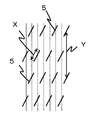
도 2는 프리프레그에 삽입된 절입의 모식도이다.
도 3은 섬유 강화 플라스틱의 제조 방법에 있어서의 배치 공정의 일례이다.
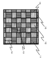
도 4는 섬유 강화 플라스틱에 있어서의 직물 프리프레그가 배치된 표면의 모식도이다.
도 5는 본 발명에 있어서의 실시 형태의 일례이다.
도 6은 본 발명에 있어서의 실시 형태의 일례이다.
도 7은 본 발명에 있어서의 실시 형태의 일례이다.1 is an example of a heat flow curve obtained as a result of differential scanning calorimetry.
2 is a schematic view of an incision inserted in a prepreg.
3 is an example of a batch process in the manufacturing method of fiber-reinforced plastics.
4 is a schematic view of a surface on which a fabric prepreg is disposed in a fiber reinforced plastic.
5 is an example of embodiment in this invention.
6 is an example of an embodiment in the present invention.
7 is an example of embodiment in this invention.
본 발명에서는, 직물 프리프레그와 불연속 섬유 프리프레그의 적층체에 있어서, 직물 프리프레그에 포함되는 열경화성 수지 A를 불연속 섬유 프리프레그에 포함되는 열경화성 수지 B보다도 경화 시간을 충분히 빠르게 함으로써, 상기 과제를 해결 가능하고, 구체적으로는, 열경화성 수지 A와 열경화성 수지 B의 관계는, 각각에 대하여 시차 주사 열량 분석계에 의해 질소 분위기 중에서 50℃부터 700℃/min으로 130℃까지 승온하고, 그 후 130℃에서 열경화 반응이 종료할 때까지 유지하는 분석을 했을 때, 열경화성 수지 A의 발열량이 열경화성 수지 A의 총발열량의 50%에 도달할 때까지의 시간 Ta(s)와, 열경화성 수지 B의 발열량이 열경화성 수지 B의 총발열량의 50%에 도달할 때까지의 시간 Tb(s)가 Tb-Ta>30의 관계를 충족하는 것(이하, 발열량 조건이라고 한다)이 필요하다. Tb-Ta≤30의 경우, 열경화성 수지 A와 열경화성 수지 B의 경화 속도의 차가 실질적으로 작아지기 때문에, 눈 흐트러짐 억제의 효과를 기대할 수 없다.In the present invention, in the laminate of the fabric prepreg and the discontinuous fiber prepreg, the above-mentioned problem is solved by making the thermosetting resin A contained in the fabric prepreg sufficiently faster than the thermosetting resin B contained in the discontinuous fiber prepreg. It is possible, and specifically, the relationship between the thermosetting resin A and the thermosetting resin B is raised to 130 ° C. in a nitrogen atmosphere at 50 ° C. to 700 ° C./min in a nitrogen atmosphere by a differential scanning calorimeter for each, and then heated at 130 ° C. The time Ta (s) until the calorific value of the thermosetting resin A reaches 50% of the total calorific value of the thermosetting resin A, and the calorific value of the thermosetting resin B The time Tb (s) until it reaches 50% of the total calorific value of B satisfies the relationship of Tb-Ta> 30 (hereinafter referred to as the calorific value condition) need. In the case of Tb-Ta≤30, since the difference in curing speed between the thermosetting resin A and the thermosetting resin B becomes substantially small, the effect of suppressing eye disturbance cannot be expected.
상기 관계를 충족할 때, 열경화성 수지 A가 열경화성 수지 B보다도 충분히 빠르게 경화하기 때문에, 가열에 의해 열경화성 수지 B의 점도가 저하되어 불연속 섬유 프리프레그에 포함되는 불연속 강화 섬유 R2가 유동할 쯤에는 열경화성 수지 A의 점도가 충분히 높아져 있어, 직물 프리프레그에 포함되는 강화 섬유 R1의 유동이 억제되어, 방직 구조의 눈 흐트러짐이 억제된다. 더 효과적으로 눈 흐트러짐을 억제하기 위해서는 Tb-Ta>150이 되도록 열경화성 수지 A 및 열경화성 수지 B를 선택하는 것이 바람직하다. 한편, 현실적인 Tb-Ta의 최댓값은 1,000이다.When the above-mentioned relationship is satisfied, since the thermosetting resin A hardens faster than the thermosetting resin B, the viscosity of the thermosetting resin B decreases due to heating, and the thermosetting property is reached when the discontinuous reinforcing fibers R 2 contained in the discontinuous fiber prepreg flow. The viscosity of the resin A is sufficiently high, so that the flow of the reinforcing fibers R 1 contained in the fabric prepreg is suppressed, and the eye disturbance of the textile structure is suppressed. In order to more effectively suppress eye disorders, it is preferable to select thermosetting resin A and thermosetting resin B so that Tb-Ta> 150. On the other hand, the maximum value of realistic Tb-Ta is 1,000.
본 발명에 있어서의 직물 프리프레그는, 방직 구조를 갖는 강화 섬유 R1과 열경화성 수지 A를 포함하는 프리프레그이다.The fabric prepreg in the present invention is a prepreg containing reinforcing fibers R 1 having a textile structure and thermosetting resin A.
강화 섬유 R1로서는, 예를 들어, 유리 섬유, 케블라 섬유, 탄소 섬유, 그래파이트 섬유, 보론 섬유, 아라미드 섬유 등이어도 된다. 그중에서도 특히 탄소 섬유는, 이들 강화 섬유 중에서도 경량이며, 게다가 비강도 및 비탄성률에 있어서 특히 우수한 성질을 갖고 있는 점에서 바람직하다.The reinforcing fiber R 1 may be, for example, glass fiber, Kevlar fiber, carbon fiber, graphite fiber, boron fiber, aramid fiber, or the like. Among them, carbon fiber is particularly preferred because it is lightweight among these reinforcing fibers and has particularly excellent properties in specific strength and inelasticity.
상기 직물은 1종류의 섬유로 이루어지는 것이어도 되고, 복수의 종류의 섬유로 이루어지는 것이어도 된다. 상기 직물은, 복수의 섬유 다발로 구성되는 것을 적절히 선택할 수 있다. 예를 들어, 서로 평행해지도록 일방향으로 정렬된 복수개의 섬유 다발과, 그들에 직교하는 보조 섬유가 서로 교착하여 방직 구조를 이루는 일방향 직물, 혹은 복수개의 섬유 다발을 2 방향으로 직성(織成)하여 이루어지는 2축 직물, 나아가 각각 평행하게 정렬된 섬유 다발을 서로 섬유 방향이 상이하도록 다단으로 적층하고, 그들을 스티칭 등으로 접합한 다축 직물 등을 사용할 수 있다. 그 중에서도 서로 직교하는 섬유 다발을 포함하는 2축 직물은 입체 형상에 대한 추종성이 우수하기 때문에 바람직하다. 상기 직물 프리프레그의 방직 구조의 형태는 특별히 한정되지 않지만, 평직, 능직, 주자직, 레노직, 모사직, 사문직 등의 다양한 방직 형태를 취해도 된다. 또한, 직물을 구성하는 섬유 다발의 폭은 모든 섬유 다발에서 균일해도 되고, 섬유 다발에 따라 상이한 폭을 갖고 있어도 된다. 각각의 섬유 다발을 구성하고 있는 섬유 필라멘트수는 특별히 한정되지 않지만, 취급성의 면에서는 1,000 내지 12,000개가 바람직하고, 1,000 내지 5,000개이면 직물의 눈 흐트러짐이 눈에 띄기 어려워지기 때문에 보다 바람직하다.The said fabric may consist of 1 type of fiber, or may consist of multiple types of fiber. As for the said fabric, what consists of several fiber bundles can be selected suitably. For example, a plurality of fiber bundles aligned in one direction so as to be parallel to each other, and an auxiliary fiber orthogonal to them intersect with each other to form a textile structure, or a plurality of fiber bundles are woven in two directions. It is possible to use a biaxial fabric composed of multi-layer fabrics, further stacked in multiple stages so that the fiber directions are aligned in parallel with each other, and bonded by stitching or the like. Among them, a biaxial fabric including a bundle of fibers orthogonal to each other is preferable because it has excellent followability to a three-dimensional shape. The shape of the textile structure of the fabric prepreg is not particularly limited, but various types of weaving such as plain weave, twill weave, runner weave, leno weave, woolen weave and serpentine weave may be employed. Further, the width of the fiber bundles constituting the fabric may be uniform among all the fiber bundles or may have different widths depending on the fiber bundles. The number of fiber filaments constituting each fiber bundle is not particularly limited, but in terms of handleability, 1,000 to 12,000 is preferable, and if it is 1,000 to 5,000, it is more preferable because the distraction of the fabric is less likely to be noticeable.
열경화성 수지 A로서는, 상기 발열량 조건을 충족하는 열경화성 수지이면 특별히 한정되지 않고, 불포화 폴리에스테르 수지, 비닐에스테르 수지, 에폭시 수지, 벤조옥사진 수지, 페놀 수지, 요소 수지, 멜라민 수지 및 폴리이미드 수지 등을 들 수 있다. 이들 수지를 변성제에 의해 변성시킨 것이나, 2종 이상의 블렌드 수지를 사용할 수도 있다. 또한, 이들 열경화성 수지는 열에 의해 자기 경화하는 수지여도 되고, 경화제나 경화 촉진제 등을 포함하는 것이어도 된다. 또한, 내열성이나 역학 특성을 향상시킬 목적에서 필러 등이 혼합되어 있는 것이어도 된다.The thermosetting resin A is not particularly limited as long as it is a thermosetting resin that satisfies the above calorific value condition, and includes unsaturated polyester resin, vinyl ester resin, epoxy resin, benzoxazine resin, phenol resin, urea resin, melamine resin and polyimide resin. Can be lifted. These resins are modified with a modifier, or two or more kinds of blend resins can also be used. Moreover, these thermosetting resins may be resins which self-cure by heat, or may contain a curing agent, a curing accelerator, or the like. Moreover, fillers etc. may be mixed for the purpose of improving heat resistance and dynamics characteristics.
본 발명에 있어서의 불연속 섬유 프리프레그란, 일방향으로 배향된 불연속 강화 섬유와 매트릭스 수지를 포함한다. 구체적으로는, 일방향으로 배향된 강화 섬유와 열경화성 수지 B를 포함하는 프리프레그에 대하여 강화 섬유를 절단하는 방향으로 복수의 절입을 삽입한 절입 프리프레그여도 되고, 일방향 프리프레그를 작게 재단한 것을 섬유 방향이 일치하도록, 또한 각각이 겹치지 않도록 배열함으로써 얻어지는 시트상 기재여도 된다. 리사이클 섬유를 유수에 의해 일방향으로 정렬시킨 섬유 기재에 수지를 함침시킨 것이어도 된다. 또한, 섬유 기재를 인장함으로써 단속적으로 섬유를 파단시킨 섬유 기재에 수지를 함침시킨 것이어도 된다. 강화 섬유를 불연속 강화 섬유 R2로 함으로써, 프리프레그 적층체를 곡면에 추종시키거나, 불연속 섬유 프리프레그를 유동시켜서 리브를 마련시키거나 할 수 있어, 복잡 형상을 갖는 섬유 강화 플라스틱을 얻을 수 있다.The discontinuous fiber prepreg in the present invention includes discontinuous reinforcing fibers oriented in one direction and a matrix resin. Specifically, for a prepreg comprising a reinforcing fiber oriented in one direction and a thermosetting resin B, a cutting prepreg in which a plurality of cuts are inserted in the direction of cutting the reinforcing fibers may be used, and a fiber cut is obtained by cutting the one-way prepreg small. A sheet-like base material obtained by arranging such that they are coincident and not overlapping each other may be sufficient. The resin may be impregnated with a fiber base material in which recycled fibers are aligned in one direction by running water. Moreover, the resin may be impregnated with the fiber base material which ruptured the fiber intermittently by pulling the fiber base material. By setting the reinforcing fibers to discontinuous reinforcing fibers R 2 , the prepreg laminate can be made to follow the curved surface, or the ribs can be provided by flowing the discontinuous fiber prepregs, whereby a fiber-reinforced plastic having a complicated shape can be obtained.
불연속 강화 섬유 R2의 소재는 특별히 한정되지 않고 유리 섬유, 케블라 섬유, 탄소 섬유, 그래파이트 섬유, 보론 섬유, 아라미드 섬유 등이어도 된다. 그중에서도 특히 탄소 섬유는, 이들 강화 섬유 소재 중에서도 경량이며, 게다가 비강도 및 비탄성률에 있어서 특히 우수한 성질을 갖고 있는 점에서 바람직하다.The material of the discontinuous reinforcing fiber R 2 is not particularly limited, and may be glass fiber, Kevlar fiber, carbon fiber, graphite fiber, boron fiber, aramid fiber or the like. Among them, carbon fiber is particularly preferable because it is lightweight among these reinforcing fiber materials and has particularly excellent properties in specific strength and inelasticity.
열경화성 수지 B로서는, 상기 발열량 조건을 충족하는 열경화성 수지이면 특별히 한정되지 않고, 불포화 폴리에스테르 수지, 비닐에스테르 수지, 에폭시 수지, 벤조옥사진 수지, 페놀 수지, 요소 수지, 멜라민 수지 및 폴리이미드 수지 등을 들 수 있다. 이들 수지를 변성제에 의해 변성시킨 것이나, 2종 이상의 블렌드 수지를 사용할 수도 있다. 또한, 이들 열경화성 수지는 열에 의해 자기 경화하는 수지여도 되고, 경화제나 경화 촉진제 등을 포함하는 것이어도 된다. 내열성이나 역학 특성을 향상시킬 목적에서 필러 등이 혼합되어 있는 것이어도 된다.The thermosetting resin B is not particularly limited as long as it is a thermosetting resin that satisfies the above calorific value condition, and includes unsaturated polyester resins, vinyl ester resins, epoxy resins, benzoxazine resins, phenol resins, urea resins, melamine resins, and polyimide resins. Can be lifted. These resins are modified with a modifier, or two or more kinds of blend resins can also be used. Moreover, these thermosetting resins may be resins which self-cure by heat, or may contain a curing agent, a curing accelerator, or the like. A filler or the like may be mixed for the purpose of improving heat resistance and mechanical properties.
상기 열경화성 수지 A 및 열경화성 수지 B로서는, 에폭시 수지를 사용하는 것이 바람직하다. 에폭시 수지를 사용함으로써 기계 특성이나 내열성이 보다 우수한 섬유 강화 플라스틱을 얻을 수 있다.As said thermosetting resin A and thermosetting resin B, it is preferable to use an epoxy resin. By using an epoxy resin, a fiber-reinforced plastic having superior mechanical properties and heat resistance can be obtained.
불연속 섬유 프리프레그에 있어서의 불연속 강화 섬유의 체적 함유율(Vf)에 대해서는 특별히 한정은 없고, 적절히 선택할 수 있지만, 충분한 역학 특성 및 형상 추종성을 발현시키기 위해서는 Vf=40 내지 65%인 것이 바람직하다.The volume content rate (Vf) of the discontinuous reinforcing fibers in the discontinuous fiber prepreg is not particularly limited, and can be appropriately selected, but is preferably Vf = 40 to 65% in order to express sufficient mechanical properties and shape followability.
이하의 설명에서는, 특히 불연속 섬유 프리프레그를 절입 프리프레그로 한 경우에 대하여 기재한다. 불연속 섬유를 절입 프리프레그로 함으로써, 정밀도가 좋은 일방향 방향성과 높은 섬유 함유율을 갖는 불연속 섬유 프리프레그를 얻을 수 있다.In the following description, in particular, the case where the discontinuous fiber prepreg is used as the cut-in prepreg is described. When the discontinuous fibers are cut into prepregs, it is possible to obtain discontinuous fiber prepregs having high precision in one direction and high fiber content.
일방향으로 배향된 강화 섬유에 절입을 삽입하여 절입 프리프레그를 제조하는 방법에 대해서는, 날을 표면에 배치한 회전날에 프리프레그를 가압하여 제조해도 되고, 톰슨 날을 사용하여 프리프레그를 간헐 프레스함으로써 제조해도 되고, 레이저를 사용하여 강화 섬유를 절단함으로써 제조해도 된다.Regarding a method of manufacturing a cut prepreg by inserting a cut into reinforcing fibers oriented in one direction, the prepreg may be pressed against a rotating blade having a blade placed on its surface, or by intermittently pressing the prepreg using a Thomson blade. You may manufacture, or you may manufacture by cutting a reinforcing fiber using a laser.
본 발명에 있어서, 절입 프리프레그는, 양호한 형상 추종성을 부여하기 위하여 실질적으로 모든 강화 섬유가 절입에 의해 절단되어 있는 것이 바람직하다. 실질적으로 모든 강화 섬유가 절입에 의해 절단되어 있다란, 절단 전의 연속 강화 섬유 개수 중 95% 이상의 개수가 절입에 의해 절단되어 있는 것을 가리킨다. 절입 프리프레그 내의 실질적으로 모든 강화 섬유가 절입에 의해 절단되어 있는지의 여부는, 1㎝폭의 샘플을 대표로서 추출하고, 10㎝ 이상의 길이의 강화 섬유를 연속 섬유로 간주하여 확인한다. 즉, 먼저, 절입 프리프레그 1층에 있어서의 임의의 개소에서, 강화 섬유의 섬유 방향과 수직인 단면을 갖도록 1㎝×1㎝의 소편을 잘라내서 경화시키고, 강화 섬유의 섬유 방향에 직각인 단면을 연마하여, 해당 단면의 화상을 얻는다. 그리고, 화상 처리에 의해 강화 섬유부와 수지부를 2치화하고, 단면에 포함되는 강화 섬유수(N1)를 카운트한다. 이어서, 절입 프리프레그 1층에 있어서의 임의의 개소에서, 강화 섬유의 섬유 방향의 거리가 20㎝가 되고, 강화 섬유의 섬유 방향과 수직인 단면을 갖도록, 20㎝×1㎝의 부분을 잘라내고, 고온에서 수지를 연소제거한다(연소제거법). 수지를 연소제거하기 위한 온도는, 수지종에 따라 상이한데, 예를 들어 에폭시 수지라면 500℃이다. 그리고, 나머지 강화 섬유로부터, 10㎝ 이상의 길이의 강화 섬유의 수(N2)를 카운트한다. N2가 N1의 5% 이하이면, 절단 전의 연속 섬유 중 95% 이상의 개수가 절입에 의해 절단되었다고 간주한다.In the present invention, it is preferable that, in order to provide good shape followability, the cut-in prepreg is cut substantially by all the reinforcing fibers. The fact that substantially all the reinforcing fibers are cut by cutting means that 95% or more of the number of continuous reinforcing fibers before cutting is cut by cutting. Whether or not substantially all the reinforcing fibers in the cutting prepreg are cut by cutting, a sample of 1 cm width is extracted as a representative, and reinforcing fibers having a length of 10 cm or more are regarded as continuous fibers. That is, first, at an arbitrary position in the first layer of the cut prepreg, a piece of 1 cm x 1 cm is cut and hardened to have a cross section perpendicular to the fiber direction of the reinforcing fiber, and a cross section perpendicular to the fiber direction of the reinforcing fiber is obtained. By grinding, an image of the cross section is obtained. Then, the reinforcing fiber portion and the resin portion are binarized by image processing, and the number of reinforcing fibers (N1) included in the cross section is counted. Subsequently, at an arbitrary position in the first layer of the cut-in prepreg, a portion of 20 cm × 1 cm is cut out so that the distance in the fiber direction of the reinforcing fiber becomes 20 cm and has a cross section perpendicular to the fiber direction of the reinforcing fiber. , Resin is burned and removed at high temperature (combustion removal method). The temperature for removing and burning the resin varies depending on the resin type, for example, 500 ° C for an epoxy resin. Then, the number N2 of reinforcing fibers having a length of 10 cm or more is counted from the remaining reinforcing fibers. When N2 is 5% or less of N1, it is considered that the number of 95% or more of the continuous fibers before cutting was cut by infeed.
프리프레그에 절입을 삽입하여 절입 프리프레그로 함으로써, 절입 프리프레그에 포함되는 강화 섬유의 섬유 길이가 불연속이 되고, 성형 시에 높은 형상 추종성을 갖는다. 그 결과, 가열·가압 시에 절입 프리프레그가 유동하여, 형에 추종하여 복잡 형상을 갖는 섬유 강화 플라스틱을 제조할 수 있다.By inserting a cut into the prepreg to form a cut-out prepreg, the fiber length of the reinforcing fibers included in the cut-out prepreg becomes discontinuous and has high shape followability during molding. As a result, the cut-in prepreg flows during heating and pressing, and can follow the mold to produce a fiber-reinforced plastic having a complicated shape.
절입 프리프레그에 삽입되는 절입의 바람직한 절입각은, 섬유의 배향 방향을 0°로 했을 때의 절입각 θ의 절댓값이 0°≤θ<45°인 것이 바람직하고, 2°≤θ<25°인 것이 양호한 표면 품위를 얻기 위해서는 보다 바람직하다. 또한, 절입 프리프레그에 삽입되는 각 절입의 길이 X는 0.1㎜≤X<50㎜인 것이 바람직하고, 0.5㎜≤X<10㎜인 것이 보다 바람직하다. 절입의 길이 X가 상기 바람직한 범위이면, 섬유 강화 플라스틱으로 했을 때에 절입의 개구가 눈에 띄지 않아 표면 품위의 저하를 방지할 수 있다.The preferred cutting angle of the cutting inserted into the cutting prepreg is that the absolute value of the cutting angle θ when the orientation direction of the fiber is 0 ° is preferably 0 ° ≤θ <45 °, and 2 ° ≤θ <25 ° It is more preferable to obtain good surface quality. In addition, the length X of each cut inserted into the cut prepreg is preferably 0.1 mm ≤ X <50 mm, more preferably 0.5 mm ≤ X <10 mm. When the length X of the infeed is within the above-mentioned preferred range, when the fiber-reinforced plastic is used, the opening of the infeed is inconspicuous and a decrease in surface quality can be prevented.
본 발명에 있어서 불연속 섬유 프리프레그에 포함되는 불연속 강화 섬유 R2의 길이 Y는 1㎜≤Y<100㎜인 것이 바람직하고, 10㎜≤Y<50㎜인 것이 양호한 역학 특성을 발현시키는 데 있어서는 보다 바람직하다. 불연속 강화 섬유 R2의 길이 Y가 상기 바람직한 범위이면 섬유 강화 플라스틱으로 했을 때에 충분한 역학 특성을 발현하는 한편, 성형 시의 형상 추종성이 손상될 일은 없다.In the present invention, the length Y of the discontinuous reinforcing fibers R 2 included in the discontinuous fiber prepreg is preferably 1 mm ≤ Y <100 mm, and more preferably 10 mm ≤ Y <50 mm to express good mechanical properties. desirable. When the length Y of the discontinuous reinforcing fibers R 2 is within the above-mentioned preferred range, sufficient mechanical properties are exhibited when the fiber-reinforced plastic is used, while shape followability during molding is not impaired.
본 발명에 있어서의 프리프레그 적층체는, 상기 직물 프리프레그 및 상기 불연속 섬유 프리프레그를 적층함으로써 얻어진다. 본 발명에 따른 프리프레그 적층체는, 적어도 한쪽 표면층에 직물 프리프레그를 가짐으로써, 섬유 강화 플라스틱의 양호한 역학 특성 및 표면 품위가 실현된다. 그 이외에는, 프리프레그 적층체의 적층 구성은, 특별히 한정되지 않고 용도에 따라서 임의로 적층되어도 된다. 프리프레그 적층체의 대표적인 적층 구성으로서는, 예를 들어, 불연속 섬유 프리프레그를, 강화 섬유의 섬유 방향을 0°로 한 경우에 [+45°/0°/-45°/90°]S의 의사 등방 적층으로 적층한 뒤, 적층체의 한쪽 표면에 직물 프리프레그를 적층함으로써 프리프레그 적층체로 해도 되고, 불연속 섬유 프리프레그를 [0°/90°]2S의 크로스 플라이 적층 구성으로 적층한 뒤, 적층체의 적어도 한쪽 표면에 직물 프리프레그를 적층함으로써 프리프레그 적층체로 해도 된다. 또한, 프리프레그 적층체는 양쪽 표면에 직물 프리프레그가 배치되어 있어도 된다. 또한, 프리프레그 적층체는 필요에 따라서 일방향 연속 섬유 프리프레그나 수지 시트 등, 다른 시트상 기재를 포함해도 된다.The prepreg laminate in the present invention is obtained by laminating the fabric prepreg and the discontinuous fiber prepreg. The prepreg laminate according to the present invention, by having a fabric prepreg on at least one surface layer, realizes good mechanical properties and surface quality of the fiber reinforced plastic. Other than that, the lamination structure of the prepreg laminate is not particularly limited and may be arbitrarily laminated depending on the application. As a typical lamination configuration of the prepreg laminate, for example, when the discontinuous fiber prepreg is set to 0 ° in the fiber direction of the reinforcing fiber, the pseudo of [+ 45 ° / 0 ° / -45 ° / 90 °] S After laminating by isotropic lamination, the fabric prepreg may be laminated on one surface of the lamination body to form a prepreg laminate, and the discontinuous fiber prepreg may be laminated in a cross ply lamination configuration of [0 ° / 90 °] 2S , followed by lamination. A prepreg laminate may be used by laminating a fabric prepreg on at least one surface of the sieve. Further, in the prepreg laminate, the fabric prepregs may be arranged on both surfaces. In addition, the prepreg laminate may contain other sheet-like base materials such as a unidirectional continuous fiber prepreg or a resin sheet as necessary.
본 발명에 있어서, 직물 프리프레그에 포함되는 열경화성 수지 A의 경화 속도보다도 불연속 섬유 프리프레그에 포함되는 열경화성 수지 B의 경화 속도가 빠른 쪽이, 성형 시의 직물의 눈 흐트러짐이 억제되기 때문에 바람직하다.In the present invention, the faster the curing rate of the thermosetting resin B contained in the discontinuous fiber prepreg than the curing rate of the thermosetting resin A contained in the fabric prepreg is preferable because the eye distraction of the fabric during molding is suppressed.
시차 주사 열량 분석계(DSC)로 관측되는 히트 플로우는, 열경화성 수지의 반응에 의한 것이며, DSC의 등온 측정에 있어서, 히트 플로우가 나타날 때까지의 시간은, 열경화성 수지의 반응 속도를 판단하는 기준이 된다. 즉, DSC의 등온 측정에서 나타나는 히트 플로우의 피크 톱(이하, 피크 톱)은 열경화성 수지의 가교 반응이 가장 활발화되는 상태를 나타내고 있어, 경화 속도의 지표로서 사용할 수 있다. 그러나, 피크 톱은 DSC 측정의 조건에 크게 의존하기 때문에, 재현성을 갖는 수치를 취득하는 것이 곤란한 경우가 있었다. 이 때문에, 본 발명에서는, 경화 속도의 지표로서, 안정적으로 재현성을 갖는 수치가 얻어지는 총발열량에 기초한 평가를 채용하였다.The heat flow observed by the differential scanning calorimetry (DSC) is due to the reaction of the thermosetting resin, and in the isothermal measurement of DSC, the time until the heat flow appears is a standard for determining the reaction rate of the thermosetting resin. . That is, the peak top (hereinafter, peak top) of the heat flow shown in the isothermal measurement of DSC indicates the state in which the crosslinking reaction of the thermosetting resin is most active, and can be used as an indicator of the curing rate. However, since the peak top is highly dependent on the conditions of DSC measurement, it may be difficult to obtain a numerical value having reproducibility. For this reason, in the present invention, as an index of the curing rate, evaluation based on the total amount of heat generated to obtain a stable and reproducible numerical value was employed.
본 발명에 있어서의 평가 방법을 이하에 상세하게 기재한다.The evaluation method in the present invention is described in detail below.
도 1은 수지 샘플에 대하여 상기 조건에서 DSC 측정을 실시했을 때에 얻어지는 경화 발열에 의한 히트 플로우 곡선(1)의 일례를 모식적으로 도시한 것이다. 임의의 베이스 라인(2)과 히트 플로우 곡선(1)으로 둘러싸인 부분이 경화 반응에 의한 발열을 나타내고, 이 면적(3)이 총발열량이 된다. 도 1에 있어서의 반응 종료 시각 Th 및 반응 개시 시각 Ts는, 이하와 같이 정의된다. 반응 종료 시각 Th는 피크 톱부터 계측 종료까지의 사이에서 발열량이 최솟값을 취한 시각으로 한다. 베이스 라인(2)은 Th에 있어서의 히트 플로우로부터 수평하게 그은 직선으로 한다. 또한, 베이스 라인(2)과 히트 플로우 곡선(1)이 계측 개시 후 최초로 교차하는 점의 시각을 반응 개시 시각 Ts로 한다. 열경화성 수지 A 및 열경화성 수지 B 각각에 대하여 열량 분석을 실시하여 히트 플로우 곡선(1)을 취득하고, 총발열량을 구하고, 반응 개시 시각 Ts로부터의 누계의 발열량(4)이 총발열량 100% 중 50%를 처음으로 초과한 시간을 반경화 시간 Ta 및 Tb로 한다. 여기에서는, 열경화성 수지 A의 반경화 시간을 Ta, 열경화성 수지 B의 반경화 시간을 Tb로 나타낸다. Ta 및 Tb는 값이 작을수록, 보다 단시간에 경화 반응의 절반이 완료된 것을 나타내고 있고, 경화가 진행하는 속도가 높은 것을 나타낸다.FIG. 1 schematically shows an example of a
본 발명의 프리프레그 적층체는 평판상이어도 되지만, 반드시 평판상은 아니어도 된다. 평판상이면, 직물 프리프레그에 불연속 섬유 프리프레그를 적층한 프리프레그 적층체를 프레스 성형이나 오토클레이브 성형 등의 가열·가압 수단에 의해 복잡 형상을 갖는 섬유 강화 플라스틱으로 성형한다. 여기서, 본 발명에 따른 「가열·가압」이란, 압력을 가하면서 행하는 가열이다. 평판상이 아닐 경우에는, 직물 프리프레그와 불연속 섬유 프리프레그를, 순서대로 형에 부형하면서 적층하여, 프리프레그 적층체로 하는 경우를 의미한다. 그 때, 직물 프리프레그와 불연속 섬유 프리프레그가 완전히 밀착해 있지 않은 경우도 본 발명의 프리프레그 적층체의 양태에 포함되는 것으로 한다.The prepreg laminate of the present invention may be in the form of a flat plate, but not necessarily in a flat plate shape. If it is flat, the prepreg laminate in which the discontinuous fiber prepreg is laminated on the fabric prepreg is molded into a fiber-reinforced plastic having a complicated shape by heating and pressing means such as press molding or autoclave molding. Here, "heating / pressurization" according to the present invention is heating performed while applying pressure. When it is not in the form of a flat plate, it means a case where the fabric prepreg and the discontinuous fiber prepreg are sequentially laminated while being molded into a mold to form a prepreg laminate. In that case, even in the case where the fabric prepreg and the discontinuous fiber prepreg are not completely in close contact, it is assumed to be included in the aspect of the prepreg laminate of the present invention.
본 발명의 프리프레그 적층체의 형태로서, 상기 프리프레그 적층체가, 상기 절입 프리프레그의 실질적으로 모든 강화 섬유가 절입에 의해 절단되어 있고, 절입의 평균 길이 x와 절입에 의해 절단된 불연속 강화 섬유 R2의 평균 길이 y가, y<6x+10이 되는 절입 프리프레그를 포함하는 것이 바람직하다.In the form of the prepreg laminate of the present invention, in the prepreg laminate, substantially all the reinforcing fibers of the infeed prepreg are cut by infeed, the average length x of infeed and discontinuous reinforcing fiber R cut by infeed It is preferable that the average length y of 2 includes a cut-in prepreg such that y <6x + 10.
도 2에, 일방향 프리프레그에 절입(5)을 삽입하여 얻어지는 절입 프리프레그의 일례를 도시한다. 본 발명에 있어서, 프리프레그 적층체에 포함되는 일방향 프리프레그가 연속한 강화 섬유만으로 이루어질 경우, 즉, 불연속 강화 섬유를 포함하지 않고, 예로서는 강화 섬유를 절단하는 절입이 하나도 삽입되어 있지 않았을 경우, 프리프레그 적층체를 가열·가압했을 때에 형의 요철부로 연속 강화 섬유가 떠받쳐져서, 복잡 형상에 형상 추종시키는 것은 매우 어렵다. 이 때문에, 본 발명에서는, 프리프레그 적층체에 형상 추종성을 부여하기 위해서, 불연속 섬유 프리프레그를 사용하는 것이어서, 절입이 삽입된 절입 프리프레그를 사용하는 것이 바람직하다. 절입의 형상이나 배치 패턴을 바꿈으로써 형상 추종성을 향상시킬 수 있다. 예를 들어, 도 2에 있어서 절입의 길이 X(이하, 절입 길이라고 하는 경우가 있다)가 길수록, 또한 절입에 의해 절단되는 불연속 강화 섬유 R2의 길이 Y(이하, 섬유 길이라고 하는 경우가 있다)가 짧을수록, 절입 프리프레그는 높은 형상 추종성을 갖는다. 따라서, 본 발명의 프리프레그 적층체는, 역학 특성보다도 형상 추종성을 중시하는 경우, y<6x+10을 충족하는 절입 프리프레그가 포함되는 것이 바람직하다.Fig. 2 shows an example of a cut prepreg obtained by inserting a
또한, 본 발명에 있어서의 절입의 평균 길이 x란, 절입 프리프레그에 삽입된 모든 절입의 길이 X의 평균값으로 하는 것이 이상적이지만, 실제로 모든 절입의 길이를 측정하는 것은 현실적이지 않기 때문에, 절입 프리프레그를 디지털 현미경 등의 촬영 장치를 사용하여 촬영한 화상을 사용하여 측정한 값으로부터 구한 평균값을 절입의 평균 길이로 한다. 절입의 패턴은, 절입 프리프레그를 임의의 위치에서 촬영하여 얻어진 화상 상의 절입의 단부끼리를 선분으로 연결함으로써 추출할 수 있다. 예를 들어, 절입이 어떠한 각도로 삽입되어 있는지, 복수의 절입은 평행하게 삽입되어 있는지, 등간격으로 삽입되어 있는지, 등의 패턴을, 하나의 절입에 있어서의 단부끼리를 선분으로 연결함으로써 추출한다. 선분의 길이를 절입의 길이로 하여, 합계 10개의 절입의 길이를 측정하고, 그의 평균값을 절입의 평균 길이로 한다. 절입은 직선상이어도 되고, 곡선상이어도 되는데, 절입이 곡선상인 경우에는, 그 절입의 단부끼리를 연결한 선분의 길이를 절입의 길이 X로 한다.In addition, the average length x of the cut in the present invention is ideal to be the average value of the length X of all cuts inserted into the cut prepreg, but since it is not practical to actually measure the length of all cuts, the cut prepreg The average value obtained from the values measured using the image photographed using a photographing apparatus such as a digital microscope is taken as the average length of cut. The pattern of cutting can be extracted by connecting the ends of the cutting on the image obtained by photographing the cutting prepreg at an arbitrary position with a line segment. For example, the angle pattern is inserted at a certain angle, whether a plurality of incisions are inserted in parallel, or at equal intervals, and the like pattern is extracted by connecting end portions in one infeed with line segments. . The length of a line segment is taken as the length of cut, and the length of 10 cuts in total is measured, and the average value thereof is taken as the average length of cut. The infeed may be straight or curved, but when the infeed is curved, the length of the line segment connecting the end portions of the infeed is taken as the length X of infeed.
마찬가지로, 본 발명에 있어서의 절입에 의해 절단된 불연속 강화 섬유 R2의 평균 길이 y는, 절입의 평균 길이와 동일하도록 디지털 현미경 등의 촬영 장치를 사용하여 촬영한 화상을 사용하여 측정한 값으로부터 구한 평균값을 절입에 의해 절단된 불연속 강화 섬유 R2의 평균 길이로 한다. 화상 상에 있어서, 강화 섬유의 섬유 방향 상에서 평행하게 인접하는 2개의 절입을 선정하고, 각각의 절입에 있어서의 단부끼리를 선분으로 연결함으로써 절입 패턴을 추출한다. 그리고, 당해 2개의 인접한 절입 사이의, 강화 섬유의 섬유 방향에 평행한 방향의 거리를 강화 섬유의 길이로 하여, 합계 10개의 선분 간에 대하여 강화 섬유의 길이를 측정하고, 그의 평균값을 절입에 의해 절단된 강화 섬유의 평균 길이 y로 한다.Similarly, the average length y of the discontinuous reinforcing fibers R 2 cut by cutting in the present invention is obtained from values measured using an image photographed using an imaging device such as a digital microscope so that it is equal to the average length of cutting. Let the average value be the average length of the discontinuous reinforcing fibers R 2 cut by cutting. On the image, two incisions adjacent to each other in parallel on the fiber direction of the reinforcing fibers are selected, and the incisions pattern is extracted by connecting the ends in each incision with line segments. Then, the length of the reinforcing fibers between the two adjacent incisions is the length of the reinforcing fibers in the direction parallel to the fiber direction of the reinforcing fibers, and the length of the reinforcing fibers is measured for a total of 10 line segments, and the average value thereof is cut by cutting. Let the average length y of the reinforcing fibers.
본 발명의 프리프레그 적층체의 다른 형태로서, 절입의 평균 길이 x와 절입에 의해 절단된 불연속 강화 섬유 R2의 평균 길이 y가, y≥6x+10이 되는 절입 프리프레그를 포함하는 것을 들 수 있다.As another form of the prepreg laminate of the present invention, the average length x of the cut and the average length y of the discontinuous reinforcing fibers R 2 cut by the cut include cut-off prepreg such that y≥6x + 10. have.
절입 프리프레그에 포함되는 불연속 강화 섬유 R2는 배향각이 랜덤하지 않고, 강화 섬유가 일방향으로 배향된 프리프레그로부터 얻어지기 때문에, 강화 섬유의 배향 불균일이나 분포 불균일이 발생할 일은 없이, 높은 역학 특성을 갖는 섬유 강화 플라스틱을 제조할 수 있다. 절입 프리프레그의 역학 특성은 절입의 형상이나 배치 패턴에 의해 향상시킬 수 있다. 예를 들어, 절입의 길이 X가 짧을수록, 또한 절입에 의해 절단된 불연속 강화 섬유 R2의 길이 Y가 길수록, 절입을 행하기 전의 원래의 프리프레그의 역학 특성으로부터의 녹다운이 낮아, 높은 역학 특성을 발현한다. 따라서, 본 발명의 프리프레그 적층체는, 형상 추종성보다도 역학 특성을 중시하는 경우에는, y≥6x+10을 충족하는 절입 프리프레그가 포함되는 것이 바람직하다.The discontinuous reinforcing fibers R 2 included in the cut-in prepregs have a random orientation and are obtained from the prepregs in which the reinforcing fibers are oriented in one direction, so that there is no orientation unevenness or distribution unevenness of the reinforcing fibers, and high mechanical properties. Fiber-reinforced plastics can be produced. The mechanical properties of the infeed prepreg can be improved by the shape of the infeed or the placement pattern. For example, the shorter the length X of the infeed, and the longer the length Y of the discontinuous reinforcing fibers R 2 cut by the infeed, the lower the knockdown from the mechanical properties of the original prepreg before the infeed, and the higher the mechanical properties. Express. Therefore, in the case where the prepreg laminate of the present invention places more importance on mechanical properties than shape followability, it is preferable that a cut prepreg satisfying y≥6x + 10 is included.
본 발명의 다른 프리프레그 적층체의 바람직한 형태로서는, 프리프레그 적층체에 포함되는 각 불연속 섬유 프리프레그의 각각의 적층면의 표면적이, 적어도 한쪽 표면층에 배치된 직물 프리프레그 외표면의 표면적 100%에 대하여 80% 이상 100% 미만이어도 된다. 직물 프리프레그의 외표면에, 적층 방향의 면에 있어서의 요철은 포함하지만, 직물 프리프레그의 측면은 포함하지 않는다. 프리프레그 적층체의 양쪽 적층면에 직물 프리프레그가 배치되는 경우에는, 양면 중에서 상기 표면적이 큰 쪽의 직물 프리프레그를 선택하고, 불연속 섬유 프리프레그와의 관계가 상기한 바와 같으면 된다. 무엇보다, 상기 양쪽 표면층의 각각의 직물 프리프레그가, 불연속 섬유 프리프레그와 상기 관계로 되어 있어도 된다. 상기 불연속 섬유 프리프레그에 포함되는 불연속 강화 섬유 R2는 섬유 길이가 짧고, 가열·가압 시의 형상 추종성을 갖고 있기 때문에, 불연속 섬유 프리프레그의 표면적을 직물 프리프레그의 표면적 100%에 대하여 80% 이상 100% 미만으로 함으로써, 가열·가압 시에 불연속 섬유 프리프레그를 신장 또는 유동시켜서 복잡 형상을 갖는 형에 추종시킬 수 있어, 형의 캐비티 내에 기재가 충전되지 않는 개소가 발생하는 것을 유효하게 방지할 수 있다.As a preferred form of another prepreg laminate of the present invention, the surface area of each laminated surface of each discontinuous fiber prepreg included in the prepreg laminate is 100% of the surface area of the outer surface of the fabric prepreg disposed on at least one surface layer. It may be 80% or more and less than 100%. The outer surface of the fabric prepreg includes irregularities on the surface in the lamination direction, but does not include the side surfaces of the fabric prepreg. When fabric prepregs are arranged on both stacked surfaces of the prepreg laminate, the fabric prepreg having the larger surface area is selected from both surfaces, and the relationship with the discontinuous fiber prepreg may be as described above. Above all, each fabric prepreg of both surface layers may have the above relationship with the discontinuous fiber prepreg. Since the discontinuous reinforcing fiber R 2 included in the discontinuous fiber prepreg has a short fiber length and has shape followability during heating and pressing, the surface area of the discontinuous fiber prepreg is 80% or more with respect to 100% of the surface area of the fabric prepreg. By setting it to less than 100%, the discontinuous fiber prepreg can be stretched or flowed to follow a mold having a complicated shape during heating and pressurization, and effectively prevent the occurrence of a place where the base material is not filled in the mold cavity. have.
구체적으로는, 섬유 강화 플라스틱을 얻기 위한 프리폼으로서 직물 프리프레그와 불연속 섬유 프리프레그를 형에 부형하면서 프리프레그 적층체를 얻는 경우, 직물 프리프레그는 신장하기 어렵기 때문에, 형의 요철에 신중하게 따르게 하는데, 불연속 섬유 프리프레그는 가열 가압함으로써 형의 요철을 따르게 할 수 있으므로, 프리폼의 시점에서는 형의 요철에 신중하게 따르게 할 필요가 없어, 프리프레그 적층체로서는 직물 프리프레그보다도 표면적이 작아진다. 직물 프리프레그를 형의 요철을 따르게 한 뒤에 불연속 섬유 프리프레그를 그 위에 배치하는 경우, 직물 프리프레그와 불연속 섬유 프리프레그는 금형의 볼록부 부근에서만 접촉하고, 오목부 부근에서는 접촉하지 않는 형태를 취한다. 이와 같이, 프리프레그 적층체를 구성하는 직물 프리프레그 및 불연속 섬유 프리프레그는 반드시 적층면 전체에서 밀착해 있을 필요는 없고, 금형의 형상에 따라서 각각의 프리프레그가 접촉하지 않는 개소를 포함하고 있어도 된다. 보다 바람직하게는, 불연속 섬유 프리프레그의 표면적이 상기 일면 또는 양면에 있어서의 직물 프리프레그의 표면적 100%에 대하여 80% 이상 95% 이하로 되는 것이다.Specifically, when a prepreg laminate is obtained while shaping a fabric prepreg and a discontinuous fiber prepreg as a preform for obtaining a fiber-reinforced plastic, the fabric prepreg is difficult to stretch, so carefully follow the irregularities of the mold. However, since the discontinuous fiber prepreg can be subjected to unevenness of the mold by heating and pressure, it is not necessary to carefully follow the unevenness of the mold at the time of preform, and the prepreg laminate has a smaller surface area than the fabric prepreg. When the fabric prepreg is made to conform to the unevenness of the mold and then the discontinuous fiber prepreg is disposed thereon, the fabric prepreg and the discontinuous fiber prepreg contact only in the vicinity of the convex portion of the mold and not in the vicinity of the concave portion. do. As described above, the fabric prepreg and the discontinuous fiber prepreg constituting the prepreg laminate do not necessarily need to be in close contact over the entire lamination surface, and may include locations where each prepreg does not contact depending on the shape of the mold. . More preferably, the surface area of the discontinuous fiber prepreg is 80% or more and 95% or less with respect to 100% of the surface area of the fabric prepreg on one side or both sides.
또한 본 발명에서는, 상기 프리프레그 적층체를 성형용의 형에 배치하는 배치 공정, 프리프레그 적층체를 예열하는 예열 공정, 프리프레그 적층체를 가열·가압하여 섬유 강화 플라스틱으로 하는 성형 공정을 포함하는 섬유 강화 플라스틱의 제조 방법을 제공한다.In the present invention, the prepreg laminate includes a batching step of placing the prepreg laminate on a mold for molding, a preheating step of preheating the prepreg laminate, and a molding step of heating and pressing the prepreg laminate to form a fiber-reinforced plastic. Provided is a method of manufacturing a fiber reinforced plastic.
상기 형의 형태는 특별히 한정되지 않지만, 일반적으로는 하형(6)과 상형(7)으로 이루어지는 것이 사용된다. 도 3은, 섬유 강화 플라스틱의 제조 방법의 각 공정의 일례를 도시한 모식도이다. 본 발명에 있어서의 배치 공정이란, 형 밖에서 제조된 상기 프리프레그 적층체(8)를 도 3의 (a)에 도시된 바와 같이 하형(6)에 배치하는 공정, 혹은 하형(6) 상에서 직물 프리프레그(9) 및 불연속 섬유 프리프레그(10)를 적층하여 상기 프리프레그 적층체(8)로 하는 공정을 말한다. 배치 공정에서는, 도 3의 (a)와 같이 프리프레그 적층체의 직물 프리프레그(9)가 배치된 표면과 하형(6) 표면이 접하도록 배치해도 되고, 혹은 불연속 섬유 프리프레그(10)가 배치된 표면과 하형(6) 표면이 접하도록 배치해도 되는데, 전자의 경우에는 직물 프리프레그를 우선적으로 가열할 수 있기 때문에 바람직하다. 프리프레그 적층체 전체를 균질하게 가열하고자 하는 경우, 하형(6)에 프리프레그 적층체(8)를 배치 후, 프리프레그 적층체(8)에 큰 압력이 부하되지 않도록 주의하면서, 프리프레그 적층체(8) 상에 상형(7)을 배치해도 된다.Although the form of the said mold is not specifically limited, Generally, what consists of a
본 발명에 있어서의 예열 공정이란, 형에 배치된 프리프레그 적층체를, 압력을 부여하기 전에 가열하는 공정이다(이하, 프리프레그 적층체에 압력을 부여하기 전에 가열하는 것을 예열이라고 한다). 본 발명에 있어서는, 예열 공정에 의해, 직물 프리프레그에 포함되는 열경화성 수지 A의 경화를 불연속 섬유 프리프레그에 포함되는 열경화성 수지 B의 경화보다도 먼저 진행시켜, 후술하는 성형 공정 실시시의 직물 프리프레그의 눈 흐트러짐을 억제할 수 있다. 프리프레그 적층체를 예열하는 방법으로서는, 배치 공정에서 프리프레그 적층체(8)를 형에 배치한 후에 상하형의 온도를 상승시킴으로써 예열해도 되고, 미리 표면이 예열된 하형(6)에 프리프레그 적층체(8)를 배치함으로써 예열해도 된다. 특히 후자의 경우에는, 배치 공정 후 즉시 예열 공정을 개시할 수 있기 때문에, 생산성을 향상시키는 점에서 바람직하다. 예열 공정을 실시하는 형의 온도는 특별히 한정되지 않지만, 100℃ 이상이면 상기 Ta와 Tb의 차에 의한 효과가 현저하게 나타나는 점에서 바람직하고, 110℃ 이상 180℃ 이하이면 보다 빠르게 수지의 경화가 진행하여 성형 시간이 단축되기 때문에 바람직하다. 프리프레그 적층체의 예열에 써버리는 시간에 대해서는 5초 이상 300초 이하인 것이 바람직하다. 예열 시간이 상기 바람직한 범위일 경우, 열경화성 수지 A의 경화를 제어하면서 충분히 진행시킬 수 있다. 보다 바람직한 예열 시간은 10초 이상 180초 이하이다.The preheating step in the present invention is a step of heating the prepreg laminate placed in the mold before applying pressure (hereinafter, heating before applying pressure to the prepreg laminate is referred to as preheating). In the present invention, by the preheating step, curing of the thermosetting resin A contained in the fabric prepreg is performed prior to curing of the thermosetting resin B contained in the discontinuous fiber prepreg, and the fabric prepreg is subjected to a molding process described later. Eye disorders can be suppressed. As a method of preheating the prepreg laminate, the
본 발명에 있어서의 성형 공정이란, 도 3의 (b)에 도시하는 바와 같이 예열 공정에서 예열된 프리프레그 적층체를 상하형으로 가열·가압하여, 섬유 강화 플라스틱으로 하는 공정이다. 예열 공정 후에 프리프레그 적층체를 가열·가압함으로써 직물 프리프레그의 변형을 억제하면서, 형상 추종성이 높은 불연속 섬유 프리프레그가 유동하고, 형의 캐비티 내에 충전한다. 이때, 불연속 섬유 프리프레그가 유동함으로써 직물 프리프레그의 측면 및 주위를 충전하는 경우가 있더라도, 본 발명에 있어서는 직물 프리프레그를 구성하는 섬유 다발의 움직임이 억제되어, 눈 흐트러짐이 방지된다. 가열·가압하는 수단은, 예를 들어 프레스기를 사용한 프레스 성형에 의해 실시되는 것이어도 된다.The molding process in the present invention is a process of heating and pressing a prepreg laminate preheated in a preheating step in a vertical heating type to form a fiber-reinforced plastic as shown in Fig. 3B. After the preheating step, the prepreg laminate is heated and pressed to suppress the deformation of the fabric prepreg, while the discontinuous fiber prepreg with high shape followability flows and fills the mold cavity. At this time, even if the discontinuous fiber prepreg flows to fill the side and the periphery of the fabric prepreg, in the present invention, the movement of the fiber bundles constituting the fabric prepreg is suppressed, and eye disturbance is prevented. The means for heating and pressing may be performed by, for example, press molding using a press machine.
본 발명의 섬유 강화 플라스틱의 제조 방법의 다른 양태로서, 프리프레그 적층체 표면의 한쪽이 불연속 섬유 프리프레그의 표면에 의해 형성되는 경우, 예를 들어, 프리프레그 적층체의 한쪽 외표면을 표면 S1로 하면, 직물 프리프레그의 표면이 표면 S1을 형성하고 있고, 상기 프리프레그 적층체의 다른 한쪽 외표면을 표면 S2로 하면, 불연속 섬유 프리프레그의 표면에서 표면 S2가 형성되어 있는 경우에 있어서, 상기 표면 S2에 접하는 형의 표면적이, 표면 S2의 표면적 100%에 대하여 100%보다 크고 200% 미만이 되는 것도 바람직하다. 여기에서 말하는 형의 표면적이란, 상기 성형 공정에서 가열·가압을 실시하기 직전에 프리프레그 적층체의 표면 S2와 접하고 있는 형에 있어서, 형을 폐쇄한 때에 형 내에 기재가 완전히 충전되었다고 가정한 경우에, 유동한 기재와 접촉할 수 있는 표면의 면적을 가리킨다. 프리프레그 적층체의 표면 S2의 표면적 100%에 대하여 상기 형의 표면적을 100%보다 크고 200% 미만으로 함으로써, 상기 성형 공정에서 불연속 섬유 프리프레그가 유동하여 형의 캐비티 내를 충분히 충전하여, 복잡 형상을 갖는 섬유 강화 플라스틱을 제조할 수 있다. 보다 바람직하게는, 110% 이상 150% 이하이다.As another aspect of the method for producing the fiber-reinforced plastic of the present invention, when one of the surfaces of the prepreg laminate is formed by the surface of the discontinuous fiber prepreg, for example, one outer surface of the prepreg laminate is surface S 1 If the surface of the fabric prepreg forms surface S 1 , and the other outer surface of the prepreg laminate is surface S 2 , when the surface S 2 is formed on the surface of the discontinuous fiber prepreg, In addition, it is also preferable that the surface area of the mold contacting the surface S 2 is greater than 100% and less than 200% with respect to 100% of the surface area of the surface S 2 . The surface area of the mold referred to herein is a case in which the base is completely filled in the mold when the mold is closed, in the mold that is in contact with the surface S 2 of the prepreg laminate immediately before heating and pressing in the molding step. Here, it indicates the area of the surface that can come into contact with the flowing substrate. By making the surface area of the mold larger than 100% and less than 200% with respect to 100% of the surface area of the surface S 2 of the prepreg laminate, discontinuous fiber prepreg flows in the molding step to sufficiently fill the cavity of the mold, making it complicated A fiber-reinforced plastic having a shape can be produced. More preferably, it is 110% or more and 150% or less.
본 발명에 따른 제조 방법에 의해 얻어지는 섬유 강화 플라스틱은, 직물 프리프레그에 기인하는 방직 구조의 표면 외관을 갖고, 불연속 섬유 프리프레그에 기인한 섬유 길이가 짧은 강화 섬유를 포함한다. 즉, 섬유 강화 플라스틱에 층 L1과 복수의 층 L2가 포함되고, 양자가 적층 구조를 취하는 것으로 하고, 상기 층 L1은 섬유 강화 플라스틱의 적어도 한쪽 표면에 존재하고, 강화 형태가 방직 구조를 갖는 강화 섬유 및 수지를 포함하고, 상기 층 L2는, 불연속 강화 섬유 및 수지를 포함하는 것으로 했을 때, 섬유 강화 플라스틱 내의 상기 층 L1의 섬유 유동도가, 1.0 내지 5.0인 섬유 강화 플라스틱이다.The fiber-reinforced plastic obtained by the production method according to the present invention includes a reinforcing fiber having a surface appearance of a textile structure resulting from a fabric prepreg and a short fiber length due to a discontinuous fiber prepreg. That is, it is assumed that the layer L 1 and the plurality of layers L 2 are included in the fiber reinforced plastic, and both have a laminated structure, and the layer L 1 is present on at least one surface of the fiber reinforced plastic, and the reinforced form has a textile structure. A fiber-reinforced plastic having a fiber flowability of the layer L 1 in the fiber-reinforced plastic, comprising the reinforcing fibers and resins to have, and the layer L 2 comprising discontinuous reinforcing fibers and resins.
상기에 있어서, 층 L1은 상기 프리프레그 적층체에 있어서의 직물 프리프레그가 경화한 층을 가리킨다. 기하 형상 디자인의 부여나 표면 품위의 향상을 위해서는 섬유 강화 플라스틱의 표면에 강화 섬유가 방직 구조를 갖는 층 L1이 마련되어 있는 것이 바람직하다. 층 L1에 포함되는 강화 섬유의 방직 구조의 형태는 특별히 한정되지 않고 예를 들어, 서로 평행해지도록 일방향으로 정렬된 복수개의 섬유 다발과, 그들에 직교하는 보조 섬유가 서로 교착하여 방직 구조를 이루는 일방향 직물, 혹은 복수개의 섬유 다발을 2 방향으로 직성하여 이루어지는 2축 직물, 나아가 각각 평행하게 정렬된 섬유 다발을 서로 섬유 방향이 상이하도록 다단으로 적층하고, 그들을 스티칭 등으로 접합한 다축 직물 등을 사용할 수 있다. 그 중에서도 서로 직교하는 섬유 다발을 포함하는 2축 직물은 입체 형상에 대한 추종성이 우수하기 때문에 바람직하고, 평직, 능직, 주자직, 레노직, 모사직, 사문직 등의 다양한 방직 형태를 취해도 된다. 또한, 직물을 구성하는 섬유 다발의 폭은 모든 섬유 다발에서 균일해도 되고, 섬유 다발에 따라 상이한 폭을 갖고 있어도 된다. 또한, 층 L2는 상기 프리프레그 적층체에 있어서의 불연속 섬유 프리프레그가 경화한 층을 나타낸다. 층 L2에 포함되는 강화 섬유는 복잡 형상에 추종하기 위하여 강화 섬유의 길이가 1 내지 100㎜인 것이 바람직하고, 10 내지 50㎜이 보다 바람직하다.In the above, the layer L 1 refers to a layer in which the fabric prepreg in the prepreg laminate is cured. In order to impart a geometric design or improve the surface quality, it is preferable that a layer L 1 having a textile structure is provided on the surface of the fiber-reinforced plastic. The form of the woven structure of the reinforcing fibers included in the layer L 1 is not particularly limited, for example, a plurality of fiber bundles aligned in one direction so as to be parallel to each other, and auxiliary fibers orthogonal to them intersect with each other to form a woven structure. One-way fabric or a biaxial fabric made by woven a plurality of fiber bundles in two directions, and furthermore, a multi-axis fabric in which fiber bundles arranged in parallel are stacked in multiple stages so that the fiber directions are different from each other, and multi-axis fabrics bonded by stitching or the like can be used. You can. Among them, a biaxial fabric comprising a bundle of fibers orthogonal to each other is preferable because it has excellent followability to a three-dimensional shape, and may take various types of textile such as plain weave, twill weave, runner weave, leno weave, woolen weave, serpentine weave. Further, the width of the fiber bundles constituting the fabric may be uniform among all the fiber bundles or may have different widths depending on the fiber bundles. Further, the layer L 2 represents a layer which is discontinuous fiber prepreg in the laminate of the prepreg cured. The reinforcing fibers included in the layer L 2 are preferably 1 to 100 mm in length and more preferably 10 to 50 mm in length to follow the complicated shape.
층 L1 및 층 L2에 포함되는 강화 섬유는 특별히 한정되지 않고 유리 섬유, 케블라 섬유, 탄소 섬유, 그래파이트 섬유, 보론 섬유, 아라미드 섬유 등이어도 된다. 그중에서도 특히 탄소 섬유는, 이들 강화 섬유 중에서도 경량이며, 게다가 비강도 및 비탄성률에 있어서 특히 우수한 성질을 갖고 있는 점에서 바람직하다. 또한, 층 L1에 포함되는 수지는, 열경화성 수지가 경화한 것이면 특별히 한정되지 않고, 불포화 폴리에스테르 수지, 비닐에스테르 수지, 에폭시 수지, 벤조옥사진 수지, 페놀 수지, 요소 수지, 멜라민 수지 및 폴리이미드 수지 등을 들 수 있지만, 이들에 한정되는 것은 아니다. 또한, 내열성이나 역학 특성을 향상시킬 목적에서 필러 등이 혼합되어 있는 것이어도 된다.The reinforcing fibers included in the layers L 1 and L 2 are not particularly limited, and may be glass fibers, Kevlar fibers, carbon fibers, graphite fibers, boron fibers, aramid fibers, or the like. Among them, carbon fiber is particularly preferred because it is lightweight among these reinforcing fibers and has particularly excellent properties in specific strength and inelasticity. Moreover, the resin contained in the layer L 1 is not particularly limited as long as the thermosetting resin is cured, and unsaturated polyester resin, vinyl ester resin, epoxy resin, benzoxazine resin, phenol resin, urea resin, melamine resin and polyimide Although resin etc. are mentioned, it is not limited to these. Moreover, fillers etc. may be mixed for the purpose of improving heat resistance and dynamics characteristics.
층 L2에 포함되는 수지로서는 열경화성 수지가 경화한 것이면 특별히 한정되지 않고, 불포화 폴리에스테르 수지, 비닐에스테르 수지, 에폭시 수지, 벤조옥사진 수지, 페놀 수지, 요소 수지, 멜라민 수지 및 폴리이미드 수지 등을 들 수 있지만, 이들에 한정되는 것은 아니다. 또한, 내열성이나 역학 특성을 향상시킬 목적에서 필러 등이 혼합되어 있는 것이어도 된다.The resin contained in the layer L 2 is not particularly limited as long as the thermosetting resin is cured, and includes unsaturated polyester resins, vinyl ester resins, epoxy resins, benzoxazine resins, phenol resins, urea resins, melamine resins, and polyimide resins. Although it is mentioned, it is not limited to these. Moreover, fillers etc. may be mixed for the purpose of improving heat resistance and dynamics characteristics.
본 발명에 있어서의 섬유 유동도란, 층 L1 중의 방직 구조를 갖는 강화 섬유의 섬유 다발의 폭을 h로 하고, 섬유 강화 플라스틱에 포함되는 h의 최댓값을 hmax, h의 최솟값을 hmin으로 했을 때, hmax/hmin로 정의되는 값을 말한다. 또한, 여기에서 말하는 섬유 다발의 폭 h란, 해당 섬유 다발을 구성하는 섬유 중, 가장 외측에 위치하는 2개의 섬유 간의 거리를 가리킨다.In the fiber flow rate in the present invention, the width of the fiber bundle of the reinforcing fiber having the textile structure in layer L 1 was h, and the maximum value of h contained in the fiber reinforced plastic was h max and the minimum value of h was h min . Where, it is the value defined by h max / h min . In addition, the width h of the fiber bundle referred to herein refers to a distance between two fibers located at the outermost side among fibers constituting the fiber bundle.
도 4는, 섬유 강화 플라스틱에 있어서의 층 L1의 외관의 예를 모식적으로 도시한 것이다. 평직을 예로서 나타냈지만, 평직에 한정되지 않고, 여러가지 방직 형태여도 된다. 종사(11) 및 횡사(12)에 의해 방직 구조가 형성되어 있다. 섬유 다발의 폭이 가장 좁은 개소(13)에서의 섬유 다발의 폭이 hmin, 섬유 다발의 폭이 가장 넓은 개소(14)에 있어서의 섬유 다발의 폭이 hmax가 된다. 층 L1을 형성하는 강화 섬유의 단부에 닿는 섬유 다발(예를 들어 섬유 다발(15))은 섬유 다발의 일부가 결여되어 있을 가능성이 있기 때문에, 섬유 유동도의 평가의 대상으로부터는 제외한다.4 schematically shows an example of the appearance of the layer L 1 in the fiber reinforced plastic. Although plain weave is shown as an example, it is not limited to plain weave, and various types of weaving may be used. The textile structure is formed by the
섬유 다발 폭은, 눈으로 보아 정규나 노기스 등을 사용하여 계측한다. 디지털 스코프를 사용하여 층 L1의 표면 화상을 취득하고, 화상 처리 소프트웨어를 이용하여 계측하는 방법도 허용된다.The fiber bundle width is visually measured using regular or nogis. Using a digital scope obtain a surface image of the layer L 1, and is also acceptable method for measuring by using the image processing software.
섬유 강화 플라스틱의 섬유 유동도가 5.0을 초과하는 경우에는, 방직 구조를 구성하는 섬유 다발의 눈 흐트러짐이 큰 것을 나타내고 있어, 표면 품위가 떨어진다. 섬유 유동도의 바람직한 상한은 2.5이다.When the fiber flow rate of the fiber-reinforced plastic exceeds 5.0, it indicates that the eye bundles of the fiber bundles constituting the textile structure are large, and the surface quality is poor. The preferred upper limit of the fiber flow rate is 2.5.
본 발명의 섬유 강화 플라스틱의 바람직한 형태로서, 상기 적층 구조를 적층 방향으로 절단한 단면에 있어서의 각각의 층 L2에 대하여 측정한 분산 파라미터가, 10% 이하로 되는 것을 들 수 있다.In a preferred form of the fiber reinforced plastic of the present invention, is a distributed-parameter measurements for each layer L 2 at the cut end surface of the stacked structure in the stacking direction, there may be mentioned that more than 10%.
여기서, 분산 파라미터란, 섬유 강화 플라스틱의 적층 방향을 가로 지르는 방향의 단면에 보이는 층 L2 중의 강화 섬유의 단면을 무작위로 100개 추출하고, 단면 형상을 타원에 근사했을 때에, 당해 100개의 단면의 긴 직경의 표준 편차/평균값을 의미한다. 상기 적층 방향을 가로 지르는 방향에 대해서는 특별히 한정은 없고, 단면을 가로 지르는 방향이면 임의의 각도를 취해도 된다. 또한, 임의의 상기 적층 방향을 가로 지르는 단면을 관찰하고, 한번이라도 상기 분산 파라미터 범위를 충족하는 단면이 존재하면, 본 요건을 충족시키는 것이라고 판단한다. 섬유 강화 플라스틱의 층 L2에 있어서, 강화 섬유가 일방향으로 배향되어 있는 경우에는 강화 섬유의 단면 형상은 동일하게 된다. 예를 들어, 섬유 방향에 대하여 직각에 가까운 단면에서는 강화 섬유의 단면 형상은 진원에 가까운 타원이 되고, 섬유 방향에 대하여 비스듬한 단면에서는 강화 섬유의 단면 형상은 긴 직경과 짧은 직경의 차가 큰 타원이 된다. 본 발명에서는, 섬유 강화 플라스틱의 적층 방향을 가로 지르는 단면에 있어서 적층 방향으로 시인할 수 있는 층 L2가 존재하고, 또한 해당 층 내에 있어서 분산 파라미터가 10% 이하인 것은, 층 L2 내에 있어서 강화 섬유가 일방향으로 배향되어 있는 것을 나타낸다. 섬유 강화 플라스틱의 각 층 L2에 포함되는 섬유가 일방향으로 배향되어 있는 경우, 섬유의 분포 불균일이나 배향 불균일이 억제되어, 섬유 강화 플라스틱이 양호한 역학 특성을 발현하기 때문에 바람직하다.Here, with the dispersion parameter, when 100 cross-sections of the reinforcing fibers in the layer L 2 seen in the cross-section in the direction transverse to the lamination direction of the fiber-reinforced plastics are randomly extracted, and the cross-sectional shape is approximated to an ellipse, Mean standard deviation / average of long diameter. There is no particular limitation on the direction crossing the lamination direction, and any angle may be taken as long as it is a direction crossing the cross section. In addition, a section crossing any of the stacking directions is observed, and it is determined that this requirement is satisfied if a section that satisfies the dispersion parameter range exists even once. In the layer L 2 of the fiber-reinforced plastic, when the reinforcing fibers are oriented in one direction, the cross-sectional shape of the reinforcing fibers becomes the same. For example, in a cross section close to a right angle to the fiber direction, the cross-sectional shape of the reinforcing fiber becomes an ellipse close to the circle, and in a cross-section oblique to the fiber direction, the cross-sectional shape of the reinforcing fiber becomes an ellipse with a difference between a long diameter and a short diameter. . In the present invention, the layer L 2 that can be visually recognized in the lamination direction in a cross section crossing the lamination direction of the fiber-reinforced plastic, and the dispersion parameter in the layer is 10% or less, is the reinforcing fiber in the layer L 2 Indicates that is oriented in one direction. When fibers included in each layer L 2 of the fiber reinforced plastic are oriented in one direction, uneven distribution and orientation unevenness of the fibers are suppressed, which is preferable because the fiber reinforced plastic exhibits good mechanical properties.
분산 파라미터는, 상기한 바와 같이 얻어진 섬유 강화 플라스틱의 단면 화상을, 디지털 스코프 등을 사용하여 취득하고, 해당 단면의 화상으로부터 무작위로 100개의 강화 섬유 단면을 선택하고, 선택한 강화 섬유의 단면 형상을 타원으로 간주하여 그의 긴 직경을 계측하고, 긴 직경의 표준 편차/평균값을 구함으로써 계측한다. 또한, 강화 섬유의 단면 형상을 타원으로 간주했을 때의 긴 직경이란, 취득된 강화 섬유 단면의 원주 상의 임의의 2점을 직선으로 연결했을 때의 직선의 길이의 최대값으로 한다.The dispersion parameter is obtained by obtaining a cross-sectional image of the fiber-reinforced plastic obtained as described above using a digital scope or the like, randomly selecting 100 reinforcing fiber cross-sections from the image of the cross-section, and ellipsizing the cross-sectional shape of the selected reinforcing fiber. It is regarded as, and its long diameter is measured, and it is measured by obtaining the standard deviation / average value of the long diameter. The long diameter when the cross-sectional shape of the reinforcing fiber is regarded as an ellipse is defined as the maximum value of the length of the straight line when any two points on the circumference of the obtained reinforcing fiber cross-section are connected in a straight line.
본 발명에서는, 섬유 강화 플라스틱이 복수의 층 L2를 갖고, 적층 방향을 가로 지르는 임의의 위치에서 절단하여 얻어지는 단면 내에 보이는 하나의 층 L2에 있어서, 강화 섬유의 단면을 무작위로 100개 추출하고, 이들의 섬유 단면 형상을 타원에 근사했을 때에, 추출된 100개의 단면의 긴 직경의 평균값 D1을 구하고, 전술한 단면과 동일한 단면 내의 다른층 L2에 있어서, 강화 섬유의 단면을 무작위로 100개 추출하고, 이들 섬유 단면 형상을 타원에 근사했을 때에, 추출된 100개의 단면의 긴 직경의 평균값 D2를 구한 경우, D1이 D2의 2배 이상으로 되는 단면이 존재하는 것이 보다 바람직한 양태이다. 상기 적층 방향을 가로 지르는 방향에 대해서는 특별히 한정은 없고, 단면을 가로 지르는 방향이면 임의의 각도를 취해도 된다.In the present invention, the fiber reinforced plastic has a plurality of layers L 2 , and in one layer L 2 seen in a cross section obtained by cutting at an arbitrary position across the stacking direction, 100 cross-sections of the reinforcing fibers are randomly extracted. , When these fiber cross-sectional shapes are approximated to an ellipse, the average value D 1 of the long diameters of the 100 extracted cross-sections is obtained, and in another layer L 2 in the same cross-section as the aforementioned cross-section, the cross-section of the reinforcing fibers is randomly 100 When it is extracted and these fiber cross-sectional shapes are approximated to an ellipse, when the average value D 2 of the long diameters of the 100 extracted cross-sections is obtained, it is more preferable that D 1 is a cross section of D 2 or more. to be. There is no particular limitation on the direction crossing the lamination direction, and any angle may be taken as long as it is a direction crossing the cross section.
D1이 D2의 2배 이상으로 된다란, 섬유 강화 플라스틱을 구성하는 복수의 층 L2에 있어서, 각 층 L2에 포함되는 강화 섬유의 배향 방향이 상이한 조가 존재하는 것을 나타낸다. 섬유 강화 플라스틱에 있어서 복수의 방향으로 강화 섬유가 배향되어 있음으로써, 섬유 강화 플라스틱이 갖는 역학적 특성이 등방적인 것이 되기 때문에 바람직하다. 또한, 3 이상의 층 L2가 존재할 때, 그중 하나의 층의 섬유 단면의 긴 직경 평균값이 다른 몇개의 층의 긴 직경 평균값의 2배 이상이 아니더라도, 그 이외의 어느 층의 긴 직경 평균값의 2배 이상이면 된다.D 1 being twice or more of D 2 indicates that in the plurality of layers L 2 constituting the fiber-reinforced plastic, there exist a group in which the orientation directions of the reinforcing fibers included in each layer L 2 are different. In fiber-reinforced plastics, it is preferable because the reinforcing fibers are oriented in a plurality of directions, so that the mechanical properties of the fiber-reinforced plastics become isotropic. Further, when the layer L 2 of 3 or more is present, even if the average value of the long diameter of the fiber cross section of one of the layers is not more than twice the average value of the long diameters of several other layers, it is twice the average value of the long diameters of any other layer. It is all you need.
본 발명의 보다 바람직한 양태로서, 섬유 강화 플라스틱이 복수의 층 L2를 갖고, 하나의 층 L2에 포함되는 강화 섬유의 길이의 평균값이, 다른층 L2에 포함되는 강화 섬유의 길이의 평균값보다도 짧은 것이 바람직하다.As a more preferred embodiment of the invention, the fiber-reinforced plastic to have a plurality of layer L 2, the length of the average value of the reinforcing fibers contained in a layer L 2, than the average value of the length of the reinforcing fibers contained in the other layer L 2 Short is preferred.
섬유 강화 플라스틱이 갖는 기계적 특성은, 섬유 강화 플라스틱에 포함되는 강화 섬유의 길이에 의존한다. 기본적으로, 섬유 강화 플라스틱에 포함되는 강화 섬유의 길이가 길수록 역학적 특성이 우수하다. 또한, 강화 섬유의 길이가 짧을수록 성형 시의 형상 추종성이 우수하다. 즉, 섬유 강화 플라스틱에 포함되는 강화 섬유의 길이는 요구되는 역학 특성이나 형상에 따라 선택된다. 섬유 강화 플라스틱이 서로 다른 섬유 길이를 갖는 층 L2를 가짐으로써, 원하는 역학 특성이나 형상을 갖는 섬유 강화 플라스틱이 얻어지기 때문에, 바람직하다. 또한, 3개 이상의 층 L2가 존재할 때, 그중 하나의 층의 강화 섬유의 길이의 평균값이 다른 몇개의 층의 강화 섬유의 길이의 평균값과 동일한 길이일지라도, 그 이외의 어느 층의 강화 섬유의 길이의 평균값과 상이한 것이면 된다. 섬유 강화 플라스틱이 복수의 층 L2를 갖고, 하나의 층 L2에 포함되는 강화 섬유의 길이의 평균값이, 다른층 L2에 포함되는 강화 섬유의 길이의 평균값보다도 짧은 것을 확인하기 위해서는, 섬유 강화 플라스틱의 수지를 연소제거함으로써 강화 섬유의 섬유 길이를 계측하는 방법을 사용한다. 구체적으로는, 얻어진 섬유 강화 플라스틱의 수지를 연소제거해서(연소제거 온도는 에폭시 수지의 경우에는 500℃), 강화 섬유를 포함하는 섬유 매트를 얻는다. 섬유 강화 플라스틱에 포함되는 강화 섬유의 섬유 길이의 평균은, 해당 섬유 매트 표면으로부터 임의로 추출한 10개의 강화 섬유의 평균값으로 한다. 강화 섬유의 길이의 평균값의 계측 후, 상기 섬유 매트의 섬유를 표면으로부터 균등하게 박리해 가고, 섬유 길이가 크게 변화한 시점에서, 그 시점에서의 섬유 매트의 표면으로부터 강화 섬유를 10개 추출하고, 다시 강화 섬유의 길이의 평균값을 구한다. 구한 강화 섬유의 길이의 평균값을 최초로 구한 강화 섬유의 평균값과 비교하고, 길이가 1㎜ 이상 상이한 경우, 섬유 강화 플라스틱에 있어서, 하나의 층 L2에 포함되는 강화 섬유의 길이의 평균값이, 다른층 L2에 포함되는 강화 섬유의 길이의 평균값보다도 짧다고 판단한다.The mechanical properties of fiber-reinforced plastics depend on the length of the reinforcing fibers contained in the fiber-reinforced plastics. Basically, the longer the length of the reinforcing fibers contained in the fiber reinforced plastic, the better the mechanical properties. In addition, the shorter the length of the reinforcing fibers, the better the shape followability during molding. That is, the length of the reinforcing fibers included in the fiber reinforced plastic is selected according to the required mechanical properties or shapes. Fiber-reinforced plastics are preferred because they have a layer L 2 having different fiber lengths, so that fiber-reinforced plastics having desired mechanical properties or shapes are obtained. Further, when three or more layers L 2 are present, the length of the reinforcing fibers of any other layer, even if the average value of the lengths of the reinforcing fibers in one of the layers is the same as the average of the lengths of the reinforcing fibers in several other layers It should just be different from the average value of. Fiber reinforced plastics having a plurality of layer L 2, the length of the average value of the reinforcing fibers contained in a layer L 2, in order to ensure that shorter than the average value of the reinforcing fiber length is included in the other layer L 2, a fiber-reinforced A method of measuring the fiber length of the reinforcing fibers by burning and removing plastic resin is used. Specifically, the resin of the obtained fiber-reinforced plastic is burned and removed (combustion-removal temperature is 500 ° C in the case of an epoxy resin) to obtain a fiber mat containing reinforcing fibers. The average fiber length of the reinforcing fibers contained in the fiber reinforced plastic is taken as the average value of ten reinforcing fibers randomly extracted from the fiber mat surface. After measuring the average value of the length of the reinforcing fibers, the fibers of the fiber mat are evenly peeled off the surface, and at the time when the fiber length is greatly changed, ten reinforcing fibers are extracted from the surface of the fiber mat at that time, Again, the average value of the length of the reinforcing fibers is obtained. When the average value of the length of the obtained reinforcing fibers is compared with the average value of the first reinforcing fibers, and when the length is different by 1 mm or more, in the fiber-reinforced plastic, the average value of the lengths of the reinforcing fibers included in one layer L 2 is different. It is judged that it is shorter than the average value of the length of the reinforcing fibers contained in L 2 .
실시예Example
이하, 실시예에 의해 본 발명을 더욱 구체적으로 설명하지만, 본 발명은 실시예에 기재된 발명에 한정되는 것은 아니다.Hereinafter, the present invention will be described more specifically by examples, but the present invention is not limited to the inventions described in the examples.
실시예에서 사용한 프리프레그의 제작 방법을 이하에 나타내었다.The preparation method of the prepreg used in the Example is shown below.
<에폭시 수지 조성물><Epoxy resin composition>
이하에 나타내는 원료를 사용하여 에폭시 수지 조성물 C1 내지 C5를 제작하였다. 에폭시 수지 조성물 C1 내지 C5의 수지 조성에 대하여 표 1에 정리하였다.Epoxy resin compositions C 1 to C 5 were produced using the raw materials shown below. Table 1 summarizes the resin compositions of the epoxy resin compositions C 1 to C 5 .
본 발명에서 사용하는 에폭시 수지 조성물의 구성 요소는 이하와 같다.The components of the epoxy resin composition used in the present invention are as follows.
·에폭시 수지· Epoxy resin
"jER(등록 상표)"828(비스페놀 A형 에폭시 수지, 미쓰비시 케미컬(주)제)."jER (registered trademark)" 828 (bisphenol A type epoxy resin, manufactured by Mitsubishi Chemical Corporation).
"jER(등록 상표)"1007FS(비스페놀 A형 에폭시 수지, 미쓰비시 케미컬(주)제)."jER (registered trademark)" 1007FS (bisphenol A type epoxy resin, manufactured by Mitsubishi Chemical Corporation).
"EPICLON(등록 상표)"N740(페놀노볼락형 에폭시 수지, DIC(주)제)."EPICLON (registered trademark)" N740 (phenol novolac-type epoxy resin, manufactured by DIC Corporation).
"스미 에폭시(등록 상표)"ELM434(디아미노디페닐메탄형 에폭시 수지, 스미또모 가가꾸 고교(주)제)."Sumi Epoxy (registered trademark)" ELM434 (diaminodiphenylmethane type epoxy resin, manufactured by Sumitomo Chemical Industries, Ltd.).
"아랄다이트(등록 상표)"MY0600(아미노페놀형 에폭시 수지, 헌츠맨·어드밴스트·머티리얼즈사제)."Araldite (registered trademark)" MY0600 (aminophenol type epoxy resin, manufactured by Huntsman Advanced Materials).
·경화제· Hardener
DICY7(디시안디아미드, 미쓰비시 케미컬(주)제).DICY7 (Dicyandiamide, manufactured by Mitsubishi Chemical Corporation).
·경화 촉진제· Curing accelerator
"Omicure(등록 상표)"24(4,4'-메틸렌비스(페닐디메틸우레아, PTI 재팬(주)제)."Omicure (registered trademark)" 24 (4,4'-methylenebis (phenyldimethylurea, manufactured by PTI Japan Co., Ltd.).
DCMU-99(3-(3,4-디클로로페닐)-1,1-디메틸우레아, 호도가야 가가꾸 고교(주)제).DCMU-99 (3- (3,4-dichlorophenyl) -1,1-dimethylurea, manufactured by Hodogaya Chemical Industries, Ltd.).
·열가소성 수지· Thermoplastic resin
"비닐렉(등록 상표)"K(폴리비닐포르말, JNC(주)제)."Vinyl Lec (registered trademark)" K (polyvinyl formal, manufactured by JNC Corporation).
"스미카엑셀(등록 상표)"PES5003P(폴리에테르술폰, 스미토모 가가꾸(주)제)."Sumika Excel (registered trademark)" PES5003P (polyethersulfone, manufactured by Sumitomo Chemical Co., Ltd.).
<에폭시 수지 조성물의 조제 방법><Preparation method of epoxy resin composition>
에폭시 수지 조성물의 주제로서, 비이커 내에 상기 에폭시 수지 및 상기 열가소성 수지를 투입하고, 150℃의 온도까지 승온시켜 30분 가열 혼련을 행하고, 60℃의 온도까지 강온시킨 후, 경화제 및 경화 촉진제를 투입하고, 10분간 혼련하여, 에폭시 수지 조성물을 얻었다.As the subject of the epoxy resin composition, the epoxy resin and the thermoplastic resin are introduced into a beaker, heated to a temperature of 150 ° C., heated and kneaded for 30 minutes, cooled to a temperature of 60 ° C., and then a curing agent and a curing accelerator are added. And kneaded for 10 minutes to obtain an epoxy resin composition.
<탄소 섬유><Carbon fiber>
"토레카(등록 상표)"T300(도레이(주)제), "토레카(등록 상표)"T700S(도레이(주)제), "토레카(등록 상표)"T1100G(도레이(주)제)"Toreka (registered trademark)" T300 (manufactured by Toray Corporation), "Toreka (registered trademark)" T700S (manufactured by Toray Corporation), "Toreka (registered trademark)" T1100G (manufactured by Toray Corporation)
<프리프레그의 제작 방법><Prepreg production method>
상기 에폭시 수지 조성물의 조제 방법에 준하여 얻어진 에폭시 수지 조성물을, 리버스 롤 코터를 사용하여 이형지 상에 도포하여, 수지 필름을 2매 제작하였다. 이어서, 시트상으로 정렬시킨 상기 탄소 섬유에 기재된 "토레카(등록 상표)"에 얻어진 수지 필름 2매를 탄소 섬유의 양면에서 겹치고, 온도 110℃, 압력 2MPa의 조건에서 가압 가열하여 에폭시 수지 조성물을 함침시켜, 프리프레그 P1 내지 P7을 얻었다. 또한, 상기 프리프레그의 제작 방법에 따라서 제작한 프리프레그에 사용한, 에폭시 수지 조성물과 탄소 섬유의 조합을 표 2에 정리하였다.The epoxy resin composition obtained in accordance with the method for preparing the epoxy resin composition was applied onto a release paper using a reverse roll coater to produce two resin films. Subsequently, the two sheets of the resin film obtained on the "Toreka (registered trademark)" described in the carbon fibers arranged in a sheet form were overlapped on both sides of the carbon fibers, and heated under pressure at a temperature of 110 ° C and a pressure of 2 MPa to obtain an epoxy resin composition. By impregnation, prepregs P 1 to P 7 were obtained. In addition, Table 2 summarizes the combination of the epoxy resin composition and the carbon fibers used in the prepreg prepared according to the above-described prepreg manufacturing method.
프리프레그 P1, 프리프레그 P5, 프리프레그 P6, 프리프레그 P7은 강화 섬유가 방직 구조를 갖는 직물 프리프레그이다. 본 실시예에서는, 불연속 섬유 프리프레그로서 절입 프리프레그를 사용하였다. 프리프레그 P2, P3 및 P4는 강화 섬유가 일방향으로 배향된 프리프레그이다. 프리프레그 P2, P3 및 P4에는 강화 섬유를 절단하는 절입을 삽입하여, 절입 프리프레그로 하였다. 상기 프리프레그를 사용하여, 이하에 기재된 성형성 평가 E1, 성형성 평가 E2, 성형성 평가 E3을 각각 실시하였다. 얻어진 결과는 표 3, 표 4, 표 5에 정리하였다.Prepreg P 1 , Prepreg P 5 , Prepreg P 6 , and Prepreg P 7 are fabric prepregs in which the reinforcing fibers have a textile structure. In this example, an infeed prepreg was used as the discontinuous fiber prepreg. The prepregs P 2 , P 3 and P 4 are prepregs in which the reinforcing fibers are oriented in one direction. In the prepreg P 2 , P 3 and P 4 , an incision to cut the reinforcing fibers was inserted to obtain an infeed prepreg. Using the prepreg, moldability evaluation E 1 , moldability evaluation E 2 , and moldability evaluation E 3 described below were performed, respectively. The obtained results are summarized in Table 3, Table 4 and Table 5.
<Ta 및 Tb의 측정><Measurement of Ta and Tb>
본 발명에 있어서의 히트 플로우 곡선(1)은 시차 주사 열량계(DSC)를 사용하여, 알루미늄제의 샘플 팬에 에폭시 수지 조성물 C1 내지 C5를 약 10mg분 봉입하여 셀 내의 샘플대에 배치하고, 레퍼런스로서의 빈 알루미늄제 샘플 팬을 레퍼런스대에 배치하고, 각각의 샘플을 질소 분위기 중에서 50℃부터 700℃/min으로 130℃까지 승온하고, 그 후 130℃에서 열경화 반응이 종료할 때까지 유지하는 분석을 행함으로써 취득하였다. 얻어진 히트 플로우 곡선(1)으로부터, 구분 구적의 사다리꼴 공식에 의해 에폭시 수지 조성물 C1 내지 C5의 총발열량을 각각 계산하고, 각각의 에폭시 수지 조성물에서 발열량이 총발열량의 50%에 도달할 때까지의 시간을 구하였다. 이하에서는, 에폭시 수지 조성물 C1 내지 C5의 발열량이 총발열량의 50%에 도달할 때까지의 시간을 각각 TC1 내지 TC5로 나타낸다. 분석의 결과, TC1=215.1초, TC2=374.4초, TC3=361.7초, TC4=171.0초, TC5=168.7초였다.In the
<성형성 평가 E1><Formation evaluation E 1 >
성형성 평가 E1에서는, 도 5에 도시하는 평판 섬유 강화 플라스틱을 제조하였다. 먼저, 각 프리프레그를 임의의 치수로 재단하고, 적층하여 프리프레그 적층체로 하였다. 이때, 프리프레그 적층체의 한쪽 표면에만 직물 프리프레그가 배치되도록 적층하였다. 그 후, 반면(盤面)의 형상이 100㎜×100㎜인 정사각형이며, 깊이 10㎜의 캐비티를 갖는 하부 금형에, 프리프레그 적층체를 직물 프리프레그가 배치된 표면이 하부 금형의 표면과 접하도록 배치하였다. 이때, 하부 금형은 미리 일정한 온도까지 승온되어 있었다. 그 후, 프리프레그 적층체 상에 하부 금형과 동일한 온도까지 승온한 상부 금형을 배치하였다. 그 후, 일정 시간 유지하여 프리프레그 적층체를 예열하였다. 일정 시간 경과 후, 프레스기로 가열·가압하여, 평판 섬유 강화 플라스틱을 제조하였다. 이 때 얻어진 섬유 강화 플라스틱의 금형에 대한 충전 상황을 관찰함과 함께 섬유 강화 플라스틱 표면의 섬유 유동도를 계산하고, 이하에 나타내는 양호, 가능, 불가의 3단계로 평가하였다.In the formability evaluation E 1 , the flat-fiber reinforced plastic shown in FIG. 5 was produced. First, each prepreg was cut to arbitrary dimensions, and laminated to obtain a prepreg laminate. At this time, the prepreg laminate was laminated so that the fabric prepreg was placed on only one surface. Thereafter, in the lower mold having a cavity having a depth of 10 mm and having a square shape of 100 mm × 100 mm, the prepreg laminate is placed so that the surface on which the fabric prepreg is placed is in contact with the surface of the lower mold. Was placed. At this time, the lower mold was heated up to a predetermined temperature in advance. Thereafter, the upper mold heated to the same temperature as the lower mold was placed on the prepreg laminate. Thereafter, the prepreg laminate was preheated by holding for a period of time. After a certain period of time, heating and pressing were performed with a press to produce flat fiber reinforced plastic. At this time, the filling condition of the obtained fiber-reinforced plastic mold was observed, and the fiber flow rate of the fiber-reinforced plastic surface was calculated, and evaluated in three steps: good, possible, and impossible.
양호: 기재가 형 내에 충전되고, 섬유 유동도가 1.0 이상 2.5 미만Good: the substrate is filled in the mold, and the fiber flow rate is 1.0 or more and less than 2.5
가능: 기재가 형 내에 충전되고, 섬유 유동도가 2.5 이상Possible: the substrate is filled in the mold, the fiber flow rate is 2.5 or more
불가: 기재가 형 내에 충전되지 않았다.No: The substrate was not filled in the mold.
<성형성 평가 E2><Formation evaluation E 2 >
성형성 평가 E2에서는, 도 6에 도시하는 리브를 갖는 섬유 강화 플라스틱을 제조하였다. 먼저, 각 프리프레그를 적층하여 프리프레그 적층체를 제조하였다. 이때, 프리프레그 적층체의 한쪽 표면에만 직물 프리프레그가 배치되도록 적층하였다. 배치 공정에서는, 반면의 형상이 100㎜×100㎜인 정사각형이며, 깊이 10㎜의 캐비티를 갖는 하부 금형에, 프리프레그 적층체를 직물 프리프레그가 배치된 표면이 하부 금형의 표면에 접하도록 배치하였다. 하부 금형은 미리 일정한 온도까지 승온되어 있었다. 그 후, 프리프레그 적층체 상에 하부 금형과 동일한 온도까지 승온한 상부 금형을 배치하였다. 그 후, 일정 시간 유지하여 프리프레그 적층체를 예열하였다. 일정 시간 경과 후, 프레스기로 프레스 성형을 실시하여, 리브를 갖는 섬유 강화 플라스틱을 얻었다. 이 때 얻어진 섬유 강화 플라스틱의 리브 높이 Z와 섬유 유동도를 계산하고, 그 값을 이하에 나타내는 양호, 가능, 불가의 3단계로 평가하였다. 또한, 여기에서 말하는 리브의 높이란 섬유 강화 플라스틱에 형성된 리브의 높이의 최댓값을 말한다.In the moldability evaluation E 2 , a fiber-reinforced plastic having ribs shown in FIG. 6 was produced. First, each prepreg was laminated to prepare a prepreg laminate. At this time, the prepreg laminate was laminated so that the fabric prepreg was placed on only one surface. In the batching process, the prepreg laminate was placed on the lower mold having a cavity having a depth of 10 mm and a square having a shape of 100 mm × 100 mm, so that the surface on which the fabric prepreg was placed is in contact with the surface of the lower mold. . The lower mold was heated up to a predetermined temperature in advance. Thereafter, the upper mold heated to the same temperature as the lower mold was placed on the prepreg laminate. Thereafter, the prepreg laminate was preheated by holding for a period of time. After a certain period of time, press molding was performed with a press machine to obtain a fiber-reinforced plastic having ribs. At this time, the rib height Z and the fiber flow rate of the fiber-reinforced plastic obtained were calculated, and the values were evaluated in three stages of good, possible, and impossible as shown below. In addition, the height of the rib here refers to the maximum value of the height of the rib formed in the fiber reinforced plastic.
양호: 세워진 리브의 높이가 5㎜ 이상이며, 섬유 유동도가 1.0 이상 2.5 미만Good: The height of the erected rib is 5 mm or more, and the fiber flow rate is 1.0 or more and less than 2.5.
가능: 세워진 리브의 높이가 5㎜ 이상이며, 섬유 유동도가 2.5 이상Possible: The height of the standing rib is 5 mm or more, and the fiber flow rate is 2.5 or more.
불가: 세워진 리브의 높이가 5㎜ 미만Impossible: The height of the erected rib is less than 5 mm
<성형성 평가 E3><Formation evaluation E 3 >
성형성 평가 E3에서는, 도 7에 도시하는 바와 같은 표면에 요철의 곡면을 갖는 섬유 강화 플라스틱을 제조하였다. 먼저, 각 프리프레그를 임의의 사이즈로 재단하고, 적층하여 프리프레그 적층체를 제조하였다. 이때, 프리프레그 적층체의 한쪽 표면에만 직물 프리프레그가 배치되도록 적층하였다. 배치 공정에서는 반면에 요철의 곡면을 갖는 170㎜×170㎜의 하부 금형에, 프리프레그 적층체를, 직물 프리프레그를 갖는 표면이 하부 금형의 표면에 접하도록 배치하였다. 이때, 하부 금형을 미리 일정한 온도까지 승온해 두었다. 그 후, 프리프레그 적층체 상에 하부 금형과 동일한 온도까지 승온한 상부 금형을 배치하였다. 그 후, 일정 시간 유지하여, 프리프레그 적층체를 예열하였다. 일정 시간 경과 후, 프레스기로 프레스 성형을 실시하여, 표면에 요철을 갖는 섬유 강화 플라스틱을 얻었다. 이 때 얻어진 섬유 강화 플라스틱의 섬유 유동도를 계산하고, 그 값을 이하에 나타내는 양호, 가능, 불가의 3단계로 평가하였다.In the evaluation of formability E 3 , a fiber-reinforced plastic having a curved surface with irregularities on the surface as shown in FIG. 7 was produced. First, each prepreg was cut to an arbitrary size, and laminated to prepare a prepreg laminate. At this time, the prepreg laminate was laminated so that the fabric prepreg was placed on only one surface. In the batch process, on the other hand, a prepreg laminate was placed in a lower mold of 170 mm × 170 mm having an uneven curved surface, and the surface having the fabric prepreg was in contact with the surface of the lower mold. At this time, the lower mold was heated up to a predetermined temperature in advance. Thereafter, the upper mold heated to the same temperature as the lower mold was placed on the prepreg laminate. Thereafter, the prepreg laminate was preheated by holding for a period of time. After a certain period of time, press molding was performed with a press to obtain a fiber-reinforced plastic having irregularities on its surface. At this time, the fiber flow rate of the obtained fiber-reinforced plastics was calculated, and the values were evaluated in three stages of good, possible, and impossible as shown below.
양호: 섬유 유동도가 1.0 이상 2.5 미만Good: Fiber flowability is 1.0 to less than 2.5
가능: 섬유 유동도가 2.5 이상Possible: Fiber flow rate is 2.5 or more
불가: 성형할 수 없었다Impossibility: could not be molded
<섬유 유동도의 측정 방법><Measurement method of fiber flow>
얻어진 섬유 강화 플라스틱의 표면을 눈으로 보아 관찰하고, 최소 스케일이 1㎜인 정규를 사용하여 hmin 및 hmax를 계측하고, 섬유 유동도를 구하였다.The surface of the obtained fiber-reinforced plastic was visually observed, h min and h max were measured using a normal with a minimum scale of 1 mm, and the fiber flow rate was obtained.
<섬유 강화 플라스틱의 단면의 관찰 방법><Method of observing the cross section of fiber-reinforced plastics>
얻어진 섬유 강화 플라스틱을 두께 방향(적층 방향)으로 절단하여, 층 구조를 노출시킨 샘플을 제작하였다. 그 후 샘플의 단면을 연마기에 의해 연마하였다. 단면을 연마한 샘플을 디지털 스코프로 관찰하고, 섬유 강화 플라스틱 단면에 보이는 층 L2의 분산 파라미터를 계측하였다.The obtained fiber-reinforced plastic was cut in the thickness direction (lamination direction) to prepare a sample exposing the layer structure. Then, the cross section of the sample was polished with a polishing machine. The sample polished on the cross section was observed with a digital scope, and the dispersion parameter of the layer L 2 seen on the fiber reinforced plastic cross section was measured.
(실시예 1)(Example 1)
프리프레그 P6을 97㎜×97㎜의 정사각형으로 재단하여, 본 발명에 있어서의 직물 프리프레그로 하였다. 다음으로 프리프레그 P3을 85㎜×85㎜의 정사각형으로 재단하고, 절입의 평균 길이가 1㎜, 절입이 강화 섬유의 배향 방향과 이루는 각도(절입 각도)에 대하여 14°인 절입에 의해, 절입에 의해 절단된 불연속 강화 섬유의 평균 길이가 25㎜가 되도록 절입을 삽입하여, 본 발명에 있어서의 절입 프리프레그로 하였다. 절입 프리프레그를 적층 구성이 [0°/90°]4S가 되도록 적층한 뒤, 적층체의 한쪽 표면에 상기 직물 프리프레그를 적층하여 프리프레그 적층체로 하였다. 이어서, 얻어진 프리프레그 적층체를 미리 130℃로 달구어진 성형성 평가 E1에 기재된 섬유 강화 플라스틱을 제조하기 위한 하부 금형에 배치하였다. 프리프레그 적층체를 배치 후, 하부 금형과 동일한 온도까지 승온한 상부 금형을 배치하고, 150초간 유지하여 프리프레그 적층체를 예열하였다. 그 후 상하 금형의 온도를 130℃로 유지한 채 면압 5MPa로 프레스기에 의해 프레스 성형을 실시하고, 섬유 강화 플라스틱을 제조하여 성형성 평가 E1을 실시하였다.The prepreg P 6 was cut into a square of 97 mm × 97 mm to prepare the fabric prepreg in the present invention. Next, the prepreg P 3 is cut into a square of 85 mm × 85 mm, and the average length of the cut is 1 mm, and the cut is cut by 14 ° with respect to the angle (cutting angle) formed with the orientation direction of the reinforcing fibers. The incisions were inserted so that the average length of the discontinuous reinforcing fibers cut by was 25 mm, to prepare the incised prepregs in the present invention. The cut prepreg was laminated so that the lamination configuration was [0 ° / 90 °] 4S , and then the fabric prepreg was laminated on one surface of the laminate to obtain a prepreg laminate. Subsequently, the obtained prepreg laminate was placed in a lower mold for producing the fiber-reinforced plastic described in Formability Evaluation E 1 , which was previously heated to 130 ° C. After the prepreg laminate was placed, the upper mold heated to the same temperature as the lower mold was placed, and held for 150 seconds to preheat the prepreg laminate. Thereafter, while maintaining the temperature of the upper and lower molds at 130 ° C, press molding was performed by a press with a surface pressure of 5 MPa, fiber-reinforced plastics were produced, and moldability evaluation E 1 was performed.
이 경우, 본 발명에 있어서의 상기 열경화성 수지 A는 상기 에폭시 수지 조성물 C4에 해당하고, 상기 열경화성 수지 B는 상기 에폭시 수지 조성물 C1에 해당하기 때문에, Tb-Ta=44.1로, 발열량 조건을 충족하고 있었다. 또한, 모든 절입 프리프레그에 삽입된 절입의 평균 길이 x와 절입에 의해 절단된 불연속 강화 섬유의 평균 길이 y의 관계는 y≥6x+10을 충족하고 있었다. 또한, 절입 프리프레그의 표면적의 직물 프리프레그의 적층 방향의 최표면의 표면적 100%에 대한 비(면적비 AR1, 이하 마찬가지)는 77%였다. 또한, 여기에서의 절입 프리프레그의 표면적이란, 직물 프리프레그와 접하는 절입 프리프레그의 표면적을 가리킨다. 또한, 프리프레그 적층체의 절입 프리프레그가 배치된 측, 즉 상기한 곳의 표면 S2에 접하는 형의 표면적은, 표면 S2의 표면적 100%에 대한 비(면적비 AR2, 이하 마찬가지)가 138%였다.In this case, since the thermosetting resin A in the present invention corresponds to the epoxy resin composition C 4 and the thermosetting resin B corresponds to the epoxy resin composition C 1 , Tb-Ta = 44.1, which satisfies the calorific value condition. I was doing. In addition, the relationship between the average length x of the cuts inserted in all the cut prepregs and the average length y of the discontinuous reinforcing fibers cut by cuts satisfied y≥6x + 10. In addition, the ratio of the surface area of the cut prepreg to 100% of the surface area of the outermost surface in the lamination direction of the fabric prepreg (area ratio AR 1 , hereinafter the same) was 77%. In addition, the surface area of the cutting prepreg here refers to the surface area of the cutting prepreg in contact with the fabric prepreg. The surface area of the prepreg stacked body on which the prepreg is disposed, that is, in contact with the surface S 2 of the above-mentioned area, has a ratio (area ratio AR 2 , hereinafter) of 100% of the surface area of the surface S 2 . %.
평가의 결과 얻어진 섬유 강화 플라스틱은, 기재가 금형의 단부까지 충전되어 있고, 섬유 유동도는 3.5였다. 또한, 각 층 L2는, 상기 분산 파라미터를 충족하고 있었다. 또한, 적층체의 적층 방향에 있어서의 동일 단면에 보이는 하나의 층 L2의 강화 섬유의 단면의 긴 직경의 평균값 D1이, 다른층 L2의 강화 섬유의 단면의 긴 직경의 평균값 D2의 2배 이상으로 되는 층 L2의 조합이 존재하고 있었다.In the fiber-reinforced plastic obtained as a result of the evaluation, the substrate was filled to the end of the mold, and the fiber flow rate was 3.5. Moreover, each layer L 2 satisfied the said dispersion parameter. In addition, the average value D 1 of the long diameter of the cross section of the reinforcing fiber of one layer L 2 seen in the same cross section in the lamination direction of the laminate is the average value D 2 of the long diameter of the cross section of the reinforcing fiber of the other layer L 2 The combination of the layer L 2 which becomes 2 times or more existed.
(실시예 2)(Example 2)
프리프레그 P6을 프리프레그 P1로 하고, 프리프레그 P3을 프리프레그 P2로 한 것 이외에는, 실시예 1과 마찬가지로 프리프레그 적층체를 제조하고, 성형성 평가 E1을 실시하였다.A prepreg laminate was prepared in the same manner as in Example 1, except that prepreg P 6 was prepreg P 1 and prepreg P 3 was prepreg P 2 , and moldability evaluation E 1 was performed.
이때, Tb-Ta=159.3으로, 발열량 조건을 충족하고 있고, 모든 절입 프리프레그에 삽입된 절입의 평균 길이 x와 절입에 의해 절단된 불연속 강화 섬유의 평균 길이 y의 관계는 y≥6x+10을 충족하고 있었다. 또한, 면적비 AR1은 77%이며 면적비 AR2는 138%였다.At this time, Tb-Ta = 159.3, which satisfies the calorific value condition, and the relationship between the average length x of the incisions inserted in all the infeed prepregs and the average length y of the discontinuous reinforcing fibers cut by incisions is y≥6x + 10. Was satisfied. The area ratio AR 1 was 77% and the area ratio AR 2 was 138%.
평가의 결과 얻어진 섬유 강화 플라스틱은, 기재가 금형의 단부까지 충전되어 있고, 섬유 유동도는 1.8이었다. 또한, 각 층 L2는, 상기 분산 파라미터를 충족하고 있었다. 또한, 적층체의 적층 방향에 있어서의 동일 단면에 보이는 하나의 층 L2의 강화 섬유의 단면의 긴 직경의 평균값 D1이, 다른층 L2의 강화 섬유의 단면의 긴 직경의 평균값 D2의 2배 이상으로 되는 층 L2의 조합이 존재하고 있었다.In the fiber-reinforced plastic obtained as a result of the evaluation, the substrate was filled to the end of the mold, and the fiber flow rate was 1.8. Moreover, each layer L 2 satisfied the said dispersion parameter. In addition, the average value D 1 of the long diameter of the cross section of the reinforcing fiber of one layer L 2 seen in the same cross section in the lamination direction of the laminate is the average value D 2 of the long diameter of the cross section of the reinforcing fiber of the other layer L 2 The combination of the layer L 2 which becomes 2 times or more existed.
(실시예 3)(Example 3)
절입 프리프레그에 삽입된 절입의 평균 길이가 1㎜이고, 절입에 의해 절단된 불연속 강화 섬유의 섬유 길이를 12.5㎜으로 한 것 이외에는, 실시예 2와 마찬가지로 프리프레그 적층체를 제조하고, 성형성 평가 E1을 실시하였다.A prepreg laminate was prepared in the same manner as in Example 2, except that the average length of the cut inserted into the cut prepreg was 1 mm, and the fiber length of the discontinuous reinforcing fibers cut by cut was set to 12.5 mm, and the moldability was evaluated. E 1 was carried out.
이때, Tb-Ta=159.3으로, 발열량 조건을 충족하고 있고, 모든 절입 프리프레그에 삽입된 절입의 평균 길이 x와 절입에 의해 절단된 불연속 강화 섬유의 평균 길이 y의 관계는 y<6x+10을 충족하고 있었다. 또한, 면적비 AR1은 77%이며, 면적비 AR2는 138%였다.At this time, Tb-Ta = 159.3, which satisfies the calorific value condition, and the relationship between the average length x of the incisions inserted in all the infeed prepregs and the average length y of the discontinuous reinforcing fibers cut by incisions is y <6x + 10. Was satisfied. The area ratio AR 1 was 77%, and the area ratio AR 2 was 138%.
평가의 결과 얻어진 섬유 강화 플라스틱은, 기재가 금형의 단부까지 충전되어 있고, 섬유 유동도는 2.1이었다. 또한, 각 층 L2는, 상기 분산 파라미터를 충족하고 있었다. 또한, 상기 D1이 상기 D2의 2배 이상으로 되는 층 L2의 조합이 존재하고 있었다.In the fiber-reinforced plastic obtained as a result of the evaluation, the substrate was filled to the end of the mold, and the fiber flow rate was 2.1. Moreover, each layer L 2 satisfied the said dispersion parameter. In addition, a combination of layers L 2 in which D 1 is twice or more of D 2 was present.
(실시예 4)(Example 4)
직물 프리프레그의 치수를 90㎜×90㎜의 정사각형으로 한 것 이외에는, 실시예 2와 마찬가지로 프리프레그 적층체를 제조하고, 성형성 평가 E1을 실시하였다.A prepreg laminate was prepared in the same manner as in Example 2 except that the fabric prepreg had a dimension of 90 mm × 90 mm, and moldability evaluation E 1 was performed.
이때, Tb-Ta=159.3으로, 발열량 조건을 충족하고 있고, 모든 절입 프리프레그에 삽입된 절입의 평균 길이 x와 절입에 의해 절단된 불연속 강화 섬유의 평균 길이 y의 관계는 y≥6x+10을 충족하고 있었다. 또한, 면적비 AR1은 89%이며, 면적비 AR2는 138%였다.At this time, Tb-Ta = 159.3, which satisfies the calorific value condition, and the relationship between the average length x of the incisions inserted in all the infeed prepregs and the average length y of the discontinuous reinforcing fibers cut by incisions is y≥6x + 10. Was satisfied. The area ratio AR 1 was 89%, and the area ratio AR 2 was 138%.
평가의 결과 얻어진 섬유 강화 플라스틱은, 기재가 금형의 단부까지 충전되어 있고, 섬유 유동도는 1.7이었다. 또한, 각 층 L2는, 상기 분산 파라미터를 충족하고 있었다. 또한, 상기 D1이 상기 D2의 2배 이상으로 되는 층 L2의 조합이 존재하고 있었다.In the fiber-reinforced plastic obtained as a result of the evaluation, the base material was filled to the end of the mold, and the fiber flow rate was 1.7. Moreover, each layer L 2 satisfied the said dispersion parameter. In addition, a combination of layers L 2 in which D 1 is twice or more of D 2 was present.
(실시예 5)(Example 5)
직물 프리프레그의 치수를 50㎜×50㎜의 정사각형으로 하였다. 또한 프리프레그 P2를 프리프레그 P4로 하고, 절입 프리프레그의 치수를 45㎜×45㎜으로 한 것 이외에는, 실시예 2와 마찬가지로 프리프레그 적층체를 제조하고, 성형성 평가 E1을 실시하였다.The fabric prepreg had a dimension of 50 mm × 50 mm square. Were also subjected to the prepreg P 2 to P 4, and a prepreg, except that the infeed 45㎜ × 45㎜ the dimensions of the prepreg, and the embodiment example 2, as in the manufacture of the prepreg laminate moldability evaluation E 1 .
이때, Tb-Ta=146.6으로, 발열량 조건을 충족하고 있고, 모든 절입 프리프레그에 삽입된 절입의 평균 길이 x와 절입에 의해 절단된 불연속 강화 섬유의 평균 길이 y의 관계는 y≥6x+10을 충족하고 있었다. 또한, 면적비 AR1은 81%이며, 면적비 AR2는 493%였다.At this time, Tb-Ta = 146.6, which satisfies the calorific value condition, and the relationship between the average length x of the incisions inserted in all the infeed prepregs and the average length y of the discontinuous reinforcing fibers cut by incisions is y≥6x + 10. Was satisfied. The area ratio AR 1 was 81%, and the area ratio AR 2 was 493%.
평가의 결과 얻어진 섬유 강화 플라스틱은, 섬유 유동도는 2.0이었지만, 기재가 금형의 단부까지 충전되지 않아, 원하는 형상이 얻어지지 않았다. 또한, 각 층 L2는, 상기 분산 파라미터를 충족하고 있었다. 또한, 상기 D1이 상기 D2의 2배 이상으로 되는 층 L2의 조합이 존재하고 있었다.The fiber-reinforced plastic obtained as a result of the evaluation had a fiber flow rate of 2.0, but the substrate was not filled to the end of the mold, so that a desired shape was not obtained. Moreover, each layer L 2 satisfied the said dispersion parameter. In addition, a combination of layers L 2 in which D 1 is twice or more of D 2 was present.
(실시예 6)(Example 6)
예열 공정에 있어서, 금형의 온도를 140℃로 하고, 예열의 시간을 120초로 한 것 이외에는 실시예 2와 마찬가지로 프리프레그 적층체를 제조하고, 성형성 평가 E1을 실시하였다.In the preheating step, a prepreg laminate was prepared in the same manner as in Example 2 except that the mold temperature was set to 140 ° C and the preheating time was set to 120 seconds, and moldability evaluation E 1 was performed.
평가의 결과 얻어진 섬유 강화 플라스틱은, 기재가 금형의 단부까지 충전되어 있고, 섬유 유동도는 1.9였다. 또한, 각 층 L2는, 상기 분산 파라미터를 충족하고 있었다. 또한, 상기 D1이 상기 D2의 2배 이상으로 되는 층 L2의 조합이 존재하고 있었다.In the fiber-reinforced plastic obtained as a result of the evaluation, the substrate was filled to the end of the mold, and the fiber flow rate was 1.9. Moreover, each layer L 2 satisfied the said dispersion parameter. In addition, a combination of layers L 2 in which D 1 is twice or more of D 2 was present.
(실시예 7)(Example 7)
예열 공정에 있어서, 금형의 온도를 120℃로 하고, 예열 시간을 180초로 한 것 이외에는 실시예 2와 마찬가지로 프리프레그 적층체를 제조하고, 성형성 평가 E1을 실시하였다.In the preheating step, a prepreg laminate was produced in the same manner as in Example 2 except that the mold temperature was set to 120 ° C and the preheating time was set to 180 seconds, and moldability evaluation E 1 was performed.
평가의 결과 얻어진 섬유 강화 플라스틱은, 기재가 금형의 단부까지 충전되어 있고, 섬유 유동도는 1.3이었다. 또한, 각 층 L2는, 상기 분산 파라미터를 충족하고 있었다. 또한, 상기 D1이 상기 D2의 2배 이상으로 되는 층 L2의 조합이 존재하고 있었다.In the fiber-reinforced plastic obtained as a result of the evaluation, the substrate was filled to the end of the mold, and the fiber flow rate was 1.3. Moreover, each layer L 2 satisfied the said dispersion parameter. In addition, a combination of layers L 2 in which D 1 is twice or more of D 2 was present.
(실시예 8)(Example 8)
프리프레그 적층체의 층 L2의 적층 구성을 [0°]4로 한 것 이외에는, 실시예 2와 마찬가지로 프리프레그 적층체를 제조하고, 성형성 평가 E1을 실시하였다.A prepreg laminate was prepared in the same manner as in Example 2 except that the lamination configuration of the layer L 2 of the prepreg laminate was [0 °] 4 , and moldability evaluation E 1 was performed.
평가의 결과 얻어진 섬유 강화 플라스틱은, 기재가 금형에 충전되어 있고, 섬유 유동도는 1.5였다. 또한, 각 층 L2는, 상기 분산 파라미터를 충족하고 있었다.In the fiber-reinforced plastic obtained as a result of the evaluation, the base material was filled in a mold, and the fiber flow rate was 1.5. Moreover, each layer L 2 satisfied the said dispersion parameter.
(실시예 9)(Example 9)
프리프레그 적층체의 적층 구성을 의사 등방 적층 [45°/0°/-45°/90°]2S로 한 것 이외에는 실시예 2와 마찬가지로 프리프레그 적층체를 제조하고, 성형성 평가 E1을 실시하였다.A prepreg laminate was prepared in the same manner as in Example 2, except that the lamination configuration of the prepreg laminate was pseudo-isotropic lamination [45 ° / 0 ° / -45 ° / 90 °] 2S , and moldability evaluation E 1 was performed. Did.
평가의 결과 얻어진 섬유 강화 플라스틱은, 기재가 금형에 충전되어 있고, 섬유 유동도는 1.3이었다. 또한, 각 층 L2는, 상기 분산 파라미터를 충족하고 있었다. 또한, 상기 D1이 상기 D2의 2배 이상으로 되는 층 L2의 조합이 존재하고 있었다.In the fiber-reinforced plastic obtained as a result of the evaluation, the base material was filled in a mold, and the fiber flow rate was 1.3. Moreover, each layer L 2 satisfied the said dispersion parameter. In addition, a combination of layers L 2 in which D 1 is twice or more of D 2 was present.
(실시예 10)(Example 10)
프리프레그 P1을 프리프레그 P6으로 하고, 프리프레그 P2를 프리프레그 P3으로 한 것 이외에는, 실시예 9와 마찬가지로 프리프레그 적층체를 제조하고, 성형성 평가 E1을 실시하였다.A prepreg laminate was prepared in the same manner as in Example 9, except that prepreg P 1 was prepreg P 6 and prepreg P 2 was prepreg P 3 , and moldability evaluation E 1 was performed.
이때, Tb-Ta=44.1로 발열량 조건을 충족하고 있고, 모든 절입 프리프레그에 삽입된 절입의 평균 길이 x와 절입에 의해 절단된 불연속 강화 섬유의 평균 길이 y의 관계는 y<6x+10을 충족하고 있었다. 또한, 면적비 AR1은 77%이며, 면적비 AR2는 138%였다.At this time, Tb-Ta = 44.1, which satisfies the calorific value condition, and the relationship between the average length x of the incisions inserted in all the infeed prepregs and the average length y of the discontinuous reinforcing fibers cut by incisions satisfies y <6x + 10. I was doing. The area ratio AR 1 was 77%, and the area ratio AR 2 was 138%.
평가의 결과 얻어진 섬유 강화 플라스틱은, 기재가 금형의 단부까지 충전되어 있고, 섬유 유동도는 3.3이었다. 또한, 각 층 L2는, 상기 분산 파라미터를 충족하고 있었다. 또한, 상기 D1이 상기 D2의 2배 이상으로 되는 층 L2의 조합이 존재하고 있었다.In the fiber-reinforced plastic obtained as a result of the evaluation, the substrate was filled to the end of the mold, and the fiber flow rate was 3.3. Moreover, each layer L 2 satisfied the said dispersion parameter. In addition, a combination of layers L 2 in which D 1 is twice or more of D 2 was present.
(실시예 11)(Example 11)
프리프레그 P1을 프리프레그 P7로 하고, 프리프레그 P2를 프리프레그 P3으로 한 것 이외에는, 실시예 2와 마찬가지로 프리프레그 적층체를 제조하고, 성형성 평가 E1을 실시하였다.A prepreg laminate was prepared in the same manner as in Example 2, except that prepreg P 1 was prepreg P 7 and prepreg P 2 was prepreg P 3 , and moldability evaluation E 1 was performed.
이때, Tb-Ta=46.4로 발열량 조건을 충족하고 있고, 모든 절입 프리프레그에 삽입된 절입의 평균 길이 x와 절입에 의해 절단된 불연속 강화 섬유의 평균 길이 y의 관계는 y≥6x+10을 충족하고 있었다. 또한, 면적비 AR1은 77%이며, 면적비 AR2는 138%였다.At this time, Tb-Ta = 46.4 satisfies the calorific value condition, and the relationship between the average length x of the incisions inserted in all the infeed prepregs and the average length y of the discontinuous reinforcing fibers cut by incisions satisfies y≥6x + 10. I was doing. The area ratio AR 1 was 77%, and the area ratio AR 2 was 138%.
평가의 결과 얻어진 섬유 강화 플라스틱은, 기재가 금형의 단부까지 충전되어 있고, 섬유 유동도는 3.6이었다. 또한, 각 층 L2는, 상기 분산 파라미터를 충족하고 있었다. 또한, 상기 D1이 상기 D2의 2배 이상으로 되는 층 L2의 조합이 존재하고 있었다.In the fiber-reinforced plastic obtained as a result of the evaluation, the substrate was filled to the end of the mold, and the fiber flow rate was 3.6. Moreover, each layer L 2 satisfied the said dispersion parameter. In addition, a combination of layers L 2 in which D 1 is twice or more of D 2 was present.
(실시예 12)(Example 12)
프리프레그 P1을 프리프레그 P5로 하고, 프리프레그 P2를 프리프레그 P4로 한 것 이외에는, 실시예 2와 마찬가지로 프리프레그 적층체를 제조하고, 성형성 평가 E1을 실시하였다.A prepreg laminate was prepared in the same manner as in Example 2, except that prepreg P 1 was prepreg P 5 and prepreg P 2 was prepreg P 4 , and moldability evaluation E 1 was performed.
이때, Tb-Ta=146.6으로 발열량 조건을 충족하고 있고, 모든 절입 프리프레그에 삽입된 절입의 평균 길이 x와 절입에 의해 절단된 불연속 강화 섬유의 평균 길이 y의 관계는 y≥6x+10을 충족하고 있었다. 또한, 면적비 AR1은 77%이며, 면적비 AR2는 138%였다.At this time, Tb-Ta = 146.6 satisfies the calorific value condition, and the relationship between the average length x of the incisions inserted in all the infeed prepregs and the average length y of the discontinuous reinforcing fibers cut by incisions satisfies y≥6x + 10. I was doing. The area ratio AR 1 was 77%, and the area ratio AR 2 was 138%.
평가의 결과 얻어진 섬유 강화 플라스틱은, 기재가 금형의 단부까지 충전되어 있고, 섬유 유동도는 2.0이었다. 또한, 각 층 L2는, 상기 분산 파라미터를 충족하고 있었다. 또한, 상기 D1이 상기 D2의 2배 이상으로 되는 층 L2의 조합이 존재하고 있었다.In the fiber-reinforced plastic obtained as a result of the evaluation, the substrate was filled to the end of the mold, and the fiber flow rate was 2.0. Moreover, each layer L 2 satisfied the said dispersion parameter. In addition, a combination of layers L 2 in which D 1 is twice or more of D 2 was present.
(실시예 13)(Example 13)
프리프레그 P1을 90㎜×90㎜의 정사각형으로 재단하여, 직물 프리프레그로 하였다. 다음으로 프리프레그 P2를 85㎜×85㎜의 정사각형으로 재단하고, 절입의 평균 길이가 1㎜, 절입 각도가 강화 섬유의 배향 방향에 대하여 14°인 절입에 의해, 절단된 불연속 강화 섬유의 평균 길이가 25㎜가 되도록 절입을 삽입하여, 절입 프리프레그로 하였다. 절입 프리프레그를 적층 구성이 [0°/90°]4S가 되도록 적층한 뒤, 적층체의 한쪽 표면에 직물 프리프레그를 적층하여 프리프레그 적층체로 하였다. 이어서, 얻어진 프리프레그 적층체를 미리 130℃로 달구어진 성형성 평가 E2에 기재된 섬유 강화 플라스틱을 제조하기 위한 하부 금형에 배치하였다. 프리프레그 적층체를 배치 후, 하부 금형과 동일한 온도까지 승온한 상부 금형을 배치하고, 150초간 유지하여 프리프레그 적층체를 예열하였다. 그 후 상하 금형의 온도를 130℃로 유지한 채 면압 5MPa로 프레스기에 의해 프레스 성형을 실시하고, 성형성 평가 E2를 실시하였다.The prepreg P 1 was cut into a square of 90 mm × 90 mm to prepare a fabric prepreg. Next, the prepreg P 2 was cut into a square of 85 mm × 85 mm, and the average length of the cut was discontinued by cutting with an average length of 1 mm and a cut angle of 14 ° with respect to the orientation direction of the reinforcing fibers. An incision was inserted so that the length was 25 mm, and an incision prepreg was obtained. The cut prepreg was laminated so that the lamination configuration was [0 ° / 90 °] 4S , and then the fabric prepreg was laminated on one surface of the laminate to obtain a prepreg laminate. Subsequently, the obtained prepreg laminate was placed in a lower mold for producing the fiber-reinforced plastic described in Formability Evaluation E 2 previously heated to 130 ° C. After the prepreg laminate was placed, the upper mold heated to the same temperature as the lower mold was placed, and held for 150 seconds to preheat the prepreg laminate. Thereafter, while maintaining the temperature of the upper and lower molds at 130 ° C, press molding was performed with a press with a surface pressure of 5 MPa, and evaluation of formability E 2 was performed.
이때, Tb-Ta=159.3으로 발열량 조건을 충족하고 있고, 모든 절입 프리프레그에 삽입된 절입의 평균 길이 x와 절입에 의해 절단된 불연속 강화 섬유의 평균 길이 y의 관계는 y≥6x+10을 충족하고 있었다. 또한, 면적비 AR1은 89%이며, 면적비 AR2는 193%였다.At this time, Tb-Ta = 159.3 satisfies the calorific value condition, and the relationship between the average length x of the incisions inserted in all the infeed prepregs and the average length y of the discontinuous reinforcing fibers cut by incisions satisfies y≥6x + 10. I was doing. The area ratio AR 1 was 89%, and the area ratio AR 2 was 193%.
평가의 결과 얻어진 섬유 강화 플라스틱은, 섬유 유동도가 1.8이었다. 또한, 높이 7㎜의 리브가 세워졌다. 또한, 각 층 L2는, 상기 분산 파라미터를 충족하고 있었다. 또한, 상기 D1이 상기 D2의 2배 이상으로 되는 층 L2의 조합이 존재하고 있었다.The fiber-reinforced plastic obtained as a result of the evaluation had a fiber flow rate of 1.8. In addition, a rib with a height of 7 mm was erected. Moreover, each layer L 2 satisfied the said dispersion parameter. In addition, a combination of layers L 2 in which D 1 is twice or more of D 2 was present.
(실시예 14)(Example 14)
절입 프리프레그를 [45°/0°/-45°/90°]2S의 적층 구성으로 적층할 때에 직물 프리프레그가 배치되는 쪽의 표면에서 8층의 절입 프리프레그를, 불연속 강화 섬유의 섬유 길이가 25㎜인 절입 프리프레그를 사용하여 적층하고, 나머지 8층을 섬유 길이가 12.5㎜인 절입 프리프레그를 사용하여 적층하여 얻어지는 프리프레그 적층체를 사용한 것 이외에는 실시예 9와 마찬가지로 프리프레그 적층체를 제조하고, 성형성 평가 E2를 실시하였다.When laminating the infeed prepreg in a lamination configuration of [45 ° / 0 ° / -45 ° / 90 °] 2S , the 8 layers of infeed prepreg on the surface on which the fabric prepreg is placed, the fiber length of the discontinuous reinforcing fibers The prepreg laminate was prepared in the same manner as in Example 9 except that a prepreg laminate obtained by laminating using a cut-in prepreg having a length of 25 mm and laminating the remaining 8 layers using a cut-in prepreg having a fiber length of 12.5 mm was used. It was manufactured and moldability evaluation E 2 was performed.
평가의 결과, 섬유 강화 플라스틱은 13㎜의 리브를 갖고 있었다. 또한, 섬유 유동도는 1.7이며, 양호한 표면 품위를 갖고 있었다. 또한, 섬유 강화 플라스틱 단면에 보이는 각 층 L2는, 상기 분산 파라미터를 충족하고 있었다. 또한, 상기 D1이 상기 D2의 2배 이상으로 되는 층 L2의 조합이 존재하고 있었다.As a result of the evaluation, the fiber-reinforced plastic had a rib of 13 mm. Further, the fiber flow rate was 1.7, and had good surface quality. In addition, each layer L 2 seen in the fiber-reinforced plastic cross-section satisfied the above dispersion parameters. In addition, a combination of layers L 2 in which D 1 is twice or more of D 2 was present.
(실시예 15)(Example 15)
프리프레그 P1을 180㎜×180㎜의 정사각형으로 재단하여, 직물 프리프레그로 하였다. 다음으로 프리프레그 P2를 170㎜×170㎜의 정사각형으로 재단하고, 절입 길이가 1㎜, 절입 각도가 강화 섬유의 배향 방향에 대하여 14°인 절입에 의해 섬유 길이가 25㎜가 되도록 절입을 삽입하고, 상기 절입 프리프레그로 하였다. 절입 프리프레그를 적층 구성이 [0°/90°]4S가 되도록 적층한 뒤, 적층체의 한쪽 표면에 직물 프리프레그를 적층하여 프리프레그 적층체로 하였다. 얻어진 프리프레그 적층체를 미리 130℃로 달구어진 하부 금형에 배치하였다. 프리프레그 적층체를 배치 후, 상부 금형을 설치하고, 150초간 유지하여 예열하였다. 그 후 금형의 온도를 130℃로 유지한 채 면압 5MPa로 프레스기에 의해 가압하고, 성형성 평가 E3을 실시하였다.The prepreg P 1 was cut into a square of 180 mm × 180 mm to prepare a fabric prepreg. Next, the prepreg P 2 is cut into a square of 170 mm × 170 mm, and a cut is inserted such that the cut length is 1 mm and the cut length is 25 mm by cutting with a cutting angle of 14 ° relative to the orientation direction of the reinforcing fibers. And it was set as the said cutting prepreg. The cut prepreg was laminated so that the lamination configuration was [0 ° / 90 °] 4S , and then the fabric prepreg was laminated on one surface of the laminate to obtain a prepreg laminate. The obtained prepreg laminate was placed in a lower mold previously heated to 130 ° C. After placing the prepreg laminate, the upper mold was installed, and held for 150 seconds to preheat. Thereafter, the temperature of the mold was maintained at 130 ° C, and pressurized by a pressing machine at a surface pressure of 5 MPa, and moldability evaluation E 3 was performed.
이때, Tb-Ta=159.3으로 발열량 조건을 충족하고 있고, 모든 절입 프리프레그에 삽입된 절입의 평균 길이 x와 절입에 의해 절단된 불연속 강화 섬유의 평균 길이 y의 관계는 y≥6x+10을 충족하고 있었다. 또한, 면적비 AR1은 89%이며, 면적비 AR2는 173%였다.At this time, Tb-Ta = 159.3, which satisfies the calorific value condition, and the relationship between the average length x of the incisions inserted in all the infeed prepregs and the average length y of the discontinuous reinforcing fibers cut by incisions satisfies y≥6x + 10. I was doing. The area ratio AR 1 was 89%, and the area ratio AR 2 was 173%.
평가의 결과 얻어진 섬유 강화 플라스틱은, 기재는 금형 내에 주름 없이 충전되어 있었다. 섬유 유동도는 1.5로, 양호한 표면 품위를 갖고 있었다. 또한, 섬유 강화 플라스틱 단면에 보이는 각 층 L2는, 상기 분산 파라미터를 충족하고 있었다. 또한, 상기 D1이 상기 D2의 2배 이상으로 되는 층 L2의 조합이 존재하고 있었다.In the fiber-reinforced plastic obtained as a result of the evaluation, the base material was filled without wrinkles in the mold. The fiber flow rate was 1.5, and it had good surface quality. In addition, each layer L 2 seen in the fiber-reinforced plastic cross-section satisfied the above dispersion parameters. In addition, a combination of layers L 2 in which D 1 is twice or more of D 2 was present.
(실시예 16)(Example 16)
프리프레그 P1을 200㎜×200㎜의 정사각형으로 재단하여, 직물 프리프레그로 하였다. 다음으로 프리프레그 P2를 170㎜×170㎜의 정사각형으로 재단하고, 절입 길이가 1㎜, 절입 각도가 강화 섬유의 배향 방향에 대하여 14°인 절입에 의해 섬유 길이가 25㎜가 되도록 절입을 삽입하여, 절입 프리프레그로 하였다. 먼저, 표면의 온도가 실온인 금형 상에 직물 프리프레그를 요철을 따르게 하면서 부형하고, 그 후 [0°/90°]4S의 적층 구성으로 적층한 절입 프리프레그 적층체를 직물 프리프레그 상에 배치하여, 프리프레그 적층체로 하였다. 이때, 직물 프리프레그와 절입 프리프레그 적층체는 일부 접촉하고 있고, 완전히 밀착해 있지는 않았다. 얻어진 프리프레그 적층체를 미리 130℃로 달구어진 하부 금형에 배치하였다. 프리프레그 적층체를 배치 후, 상부 금형을 설치하고, 150초간 유지하여 예열하였다. 그 후 금형의 온도를 130℃로 유지한 채 면압 5MPa로 프레스기에 의해 가압하고, 성형성 평가 E3을 실시하였다.The prepreg P 1 was cut into a square of 200 mm × 200 mm to prepare a fabric prepreg. Next, the prepreg P 2 is cut into a square of 170 mm × 170 mm, and a cut is inserted such that the cut length is 1 mm and the cut length is 25 mm by cutting with a cutting angle of 14 ° relative to the orientation direction of the reinforcing fibers. Thus, it was set as a cut prepreg. First, a fabric prepreg is molded on a mold having a surface temperature of room temperature while conforming to irregularities, and then a cut-in prepreg laminate laminated in a lamination configuration of [0 ° / 90 °] 4S is placed on the fabric prepreg Thus, a prepreg laminate was used. At this time, the fabric prepreg and the cut-in prepreg laminate were partially in contact with each other, and were not completely adhered. The obtained prepreg laminate was placed in a lower mold previously heated to 130 ° C. After placing the prepreg laminate, the upper mold was installed, and held for 150 seconds to preheat. Thereafter, the temperature of the mold was maintained at 130 ° C, and pressurized by a pressing machine at a surface pressure of 5 MPa, and moldability evaluation E 3 was performed.
이때, Tb-Ta=159.3으로 발열량 조건을 충족하고 있고, 모든 절입 프리프레그에 삽입된 절입의 평균 길이 x와 절입에 의해 절단된 불연속 강화 섬유의 평균 길이 y의 관계는 y≥6x+10을 충족하고 있었다. 또한, 면적비 AR1은 72%이며, 면적비 AR2는 173%였다.At this time, Tb-Ta = 159.3 satisfies the calorific value condition, and the relationship between the average length x of the incisions inserted in all the infeed prepregs and the average length y of the discontinuous reinforcing fibers cut by incisions satisfies y≥6x + 10. I was doing. The area ratio AR 1 was 72%, and the area ratio AR 2 was 173%.
평가의 결과 얻어진 섬유 강화 플라스틱은, 기재는 금형 내에 주름 없이 충전되어 있었다. 섬유 유동도는 1.7로, 양호한 표면 품위를 갖고 있었다. 또한, 섬유 강화 플라스틱 단면에 보이는 각 층 L2는, 상기 분산 파라미터를 충족하고 있었다. 또한, 상기 D1이 상기 D2의 2배 이상으로 되는 층 L2의 조합이 존재하고 있었다.In the fiber-reinforced plastic obtained as a result of the evaluation, the base material was filled without wrinkles in the mold. The fiber flow rate was 1.7, and had a good surface quality. In addition, each layer L 2 seen in the fiber-reinforced plastic cross-section satisfied the above dispersion parameters. In addition, a combination of layers L 2 in which D 1 is twice or more of D 2 was present.
(비교예 1)(Comparative Example 1)
프리프레그 P2를 프리프레그 P3로 하고, 예열의 시간을 30초로 한 것 이외에는 실시예 2와 마찬가지로 프리프레그 적층체를 제조하고, 성형성 평가 E1을 실시하였다. 또한, 프리프레그 P3에 포함되어 있는 수지는 프리프레그 P1에 포함되어 있는 수지와 동일한 것이었다. 따라서, 직물 프리프레그에 포함되는 열경화성 수지 A의 Ta와, 절입 프리프레그에 포함되는 열경화성 수지 B의 Tb는, 발열량 조건을 충족하지 않았다.A prepreg laminate was prepared in the same manner as in Example 2 except that the prepreg P 2 was prepreg P 3 and the preheating time was 30 seconds, and moldability evaluation E 1 was performed. In addition, the resin contained in the prepreg P 3 was the same as the resin contained in the prepreg P 1 . Therefore, Ta of the thermosetting resin A contained in the fabric prepreg and Tb of the thermosetting resin B contained in the cut prepreg did not satisfy the calorific value condition.
평가의 결과, 얻어진 섬유 강화 플라스틱의 섬유 유동도는 3.8이며, 직물 프리프레그의 눈 흐트러짐이 눈에 띄어서 표면 품위가 나빴다.As a result of the evaluation, the fiber flowability of the obtained fiber-reinforced plastic was 3.8, and the eye predisposition of the fabric prepreg was noticeable, so that the surface quality was poor.
(비교예 2)(Comparative Example 2)
프리프레그 P2에 절입을 삽입하지 않고, 절입 프리프레그로 하지 않은 것 이외에는 실시예 2와 마찬가지로 프리프레그 적층체를 제조하고, 성형성 평가 E1을 실시하였다.A prepreg laminate was produced in the same manner as in Example 2, except that no infeed was inserted into the prepreg P 2 and not a cut prepreg, and moldability evaluation E 1 was performed.
평가의 결과 얻어진 섬유 강화 플라스틱은, 섬유 유동도는 1.8이었지만, 기재가 금형에 끝까지 충전되지 않았다.The fiber-reinforced plastic obtained as a result of the evaluation had a fiber flow rate of 1.8, but the base material was not filled to the mold.
(비교예 3)(Comparative Example 3)
예열 공정을 실시하지 않은 것 이외에는 실시예 2와 마찬가지로 프리프레그 적층체를 제조하고, 성형성 평가 E1을 실시하였다. 즉, 하부 금형에 프리프레그 적층체를 배치 후 즉시 성형 공정으로 이행하여 섬유 강화 플라스틱을 제조하였다.A prepreg laminate was prepared in the same manner as in Example 2 except that the preheating step was not performed, and moldability evaluation E 1 was performed. That is, after placing the prepreg laminate in the lower mold, the fiber reinforced plastic was manufactured by immediately moving to the molding process.
평가의 결과 얻어진 섬유 강화 플라스틱은, 섬유 유동도가 4.3이며, 직물의 눈 흐트러짐이 눈에 띄어서 표면 품위가 나빴다.As a result of the evaluation, the fiber-reinforced plastic obtained had a fiber flow rate of 4.3 and a noticeable disturbance of the fabric, resulting in poor surface quality.
(비교예 4)(Comparative Example 4)
프리프레그 P2를 프리프레그 P3으로 하고, 예열의 시간을 30초로 한 것 이외에는 실시예 13과 마찬가지로 프리프레그 적층체를 제조하고, 성형성 평가 E2를 실시하였다.A prepreg laminate was prepared in the same manner as in Example 13, except that prepreg P 2 was prepreg P 3 and the preheating time was 30 seconds, and moldability evaluation E 2 was performed.
평가의 결과, 얻어진 섬유 강화 플라스틱의 섬유 유동도는 2.7이며, 직물 프리프레그의 눈 흐트러짐이 눈에 띄어서 표면 품위는 나빴다. 또한, 높이 7㎜의 리브가 세워졌다.As a result of the evaluation, the fiber flow rate of the obtained fiber-reinforced plastic was 2.7, and the eye predisposition of the fabric prepreg was noticeable, so that the surface quality was poor. In addition, a rib with a height of 7 mm was erected.
(비교예 5)(Comparative Example 5)
프리프레그 P2에 절입을 삽입하지 않고, 절입 프리프레그로 하지 않은 것 이외에는 실시예 13과 마찬가지로 프리프레그 적층체를 제조하고, 성형성 평가 E2를 실시하였다.A prepreg laminate was produced in the same manner as in Example 13, except that no infeed was inserted into the prepreg P 2 and not a cut prepreg, and moldability evaluation E 2 was performed.
평가의 결과 얻어진 섬유 강화 플라스틱은, 섬유 유동도는 1.3이었지만, 리브의 높이는 3㎜이며, 리브부에의 기재의 충전이 극단적으로 나빴다.The fiber-reinforced plastic obtained as a result of the evaluation had a fiber flow rate of 1.3, but the height of the rib was 3 mm, and the filling of the substrate to the rib portion was extremely bad.
(비교예 6)(Comparative Example 6)
예열 공정을 실시하지 않은 것 이외에는 실시예 13과 마찬가지로 프리프레그 적층체를 제조하고, 성형성 평가 E2를 실시하였다. 즉, 하부 금형에 프리프레그 적층체를 배치 후 즉시 성형 공정으로 이행하여 섬유 강화 플라스틱을 제조하였다.A prepreg laminate was prepared in the same manner as in Example 13 except that the preheating step was not performed, and moldability evaluation E 2 was performed. That is, after placing the prepreg laminate in the lower mold, the fiber reinforced plastic was manufactured by immediately moving to the molding process.
평가의 결과 얻어진 섬유 강화 플라스틱은, 섬유 유동도가 4.3이며, 직물의 눈 흐트러짐이 눈에 띄어서 표면 품위가 나빴다.As a result of the evaluation, the fiber-reinforced plastic obtained had a fiber flow rate of 4.3 and a noticeable disturbance of the fabric, resulting in poor surface quality.
(비교예 7)(Comparative Example 7)
프리프레그 P2를 프리프레그 P3으로 하고, 예열의 시간을 30초로 한 것 이외에는 실시예 15와 마찬가지로 프리프레그 적층체를 제조하고, 성형성 평가 E3을 실시하였다.A prepreg laminate was prepared in the same manner as in Example 15, except that prepreg P 2 was prepreg P 3 and the preheating time was 30 seconds, and moldability evaluation E 3 was performed.
평가의 결과, 얻어진 섬유 강화 플라스틱의 섬유 유동도는 2.7이며, 직물 프리프레그의 눈 흐트러짐이 눈에 띄어서 표면 품위는 나빴다.As a result of the evaluation, the fiber flow rate of the obtained fiber-reinforced plastic was 2.7, and the eye predisposition of the fabric prepreg was noticeable, so that the surface quality was poor.
(비교예 8)(Comparative Example 8)
프리프레그 P2에 절입을 삽입하지 않고, 절입 프리프레그로 하지 않은 것 이외에는 실시예 15와 마찬가지로 프리프레그 적층체를 제조하고, 성형성 평가 E3을 실시하였다.Without inserting mouth section in the prepreg P 2, producing the prepreg laminate in like manner as Example 15 except that no notches in the prepreg, which was then subjected to formability evaluation E 3.
평가의 결과 얻어진 섬유 강화 플라스틱은, 성형 공정 시에 기재의 주름을 물고 들어가버려, 성형할 수 없었다.The fiber-reinforced plastic obtained as a result of the evaluation was able to be molded by biting the wrinkles of the substrate during the molding process.
(비교예 9)(Comparative Example 9)
예열 공정을 실시하지 않은 것 이외에는 실시예 15와 마찬가지로 프리프레그 적층체를 제조하고, 성형성 평가 E3을 실시하였다. 즉, 하부 금형에 프리프레그 적층체를 배치 후 즉시 성형 공정으로 이행하여 섬유 강화 플라스틱을 제조하였다.A prepreg laminate was prepared in the same manner as in Example 15 except that the preheating step was not performed, and moldability evaluation E 3 was performed. That is, after placing the prepreg laminate in the lower mold, the fiber reinforced plastic was manufactured by immediately moving to the molding process.
평가의 결과 얻어진 섬유 강화 플라스틱은, 섬유 유동도는 4.3이며, 직물의 눈 흐트러짐이 눈에 띄어서 표면 품위가 나빴다.As a result of the evaluation, the fiber-reinforced plastic obtained had a fiber flow rate of 4.3 and a noticeable disturbance of the fabric, resulting in poor surface quality.


본 발명에 따르면, 직물 프리프레그와 불연속 섬유 프리프레그를 조합하더라도 성형 시의 눈 흐트러짐이 적은 프리프레그 적층체를 얻으므로, 외판 부재로서 적합한 섬유 강화 플라스틱을 얻을 수 있다. 이러한 외판 부재는 항공기, 우주기, 자동차, 철도, 선박, 전기 제품, 스포츠 등의 구조 용도로 전개할 수 있다.According to the present invention, even if the fabric prepreg and the discontinuous fiber prepreg are combined, a prepreg laminate with less eye disturbance during molding can be obtained, so that a fiber reinforced plastic suitable as an outer plate member can be obtained. The outer plate member may be deployed for structural applications such as aircraft, spacecraft, automobiles, railroads, ships, electrical appliances, and sports.
1: 히트 플로우 곡선
2: 베이스 라인
3: 총발열량
4: 총발열량의 50%의 발열량
5: 절입
6: 하형
7: 상형
8: 프리프레그 적층체
9: 직물 프리프레그
10: 불연속 섬유 프리프레그
11: 종사
12: 횡사
13: 섬유 다발의 최소폭
14: 섬유 다발의 최대폭
15: 층 L1 단부의 섬유 다발
Z: 리브의 높이1: Heat flow curve
2: Baseline
3: Total heat generation
4: 50% of total heating value
5: infeed
6: Hahyung
7: Hieroglyph
8: Prepreg laminate
9: Fabric prepreg
10: discontinuous fiber prepreg
11: Engage
12: Sheep
13: minimum width of the fiber bundle
14: maximum width of the fiber bundle
15: Fiber bundle at the end of layer L 1
Z: Rib height
Claims (12)
상기 직물 프리프레그는, 방직 구조를 갖는 강화 섬유 R1과 열경화성 수지 A를 포함하고,
상기 불연속 섬유 프리프레그는, 일방향으로 배향된 불연속 강화 섬유 R2와 열경화성 수지 B를 포함하고,
상기 열경화성 수지 A와 상기 열경화성 수지 B가 하기 발열량 조건을 충족하는, 프리프레그 적층체.
발열량 조건: 상기 열경화성 수지 A 및 상기 열경화성 수지 B 각각을, 시차 주사 열량 분석계에 의해 질소 분위기 중에서 50℃부터 700℃/min으로 130℃까지 승온하고, 열경화 반응이 종료될 때까지 130℃로 유지했을 때, Tb-Ta>30
여기서,
Ta(s): 열경화성 수지 A의 발열량이 열경화성 수지 A의 총발열량의 50%에 도달할 때까지의 시간
Tb(s): 열경화성 수지 B의 발열량이 열경화성 수지 B의 총발열량의 50%에 도달할 때까지의 시간A prepreg laminate comprising arranging a fabric prepreg on at least one surface layer and a discontinuous fiber prepreg,
The fabric prepreg includes a reinforcing fiber R 1 having a textile structure and a thermosetting resin A,
The discontinuous fiber prepreg includes discontinuous reinforcing fibers R 2 oriented in one direction and a thermosetting resin B,
The prepreg laminate in which the thermosetting resin A and the thermosetting resin B satisfy the following calorific value conditions.
Calorific value condition: The thermosetting resin A and the thermosetting resin B were each heated to 130 ° C. in a nitrogen atmosphere from 50 ° C. to 700 ° C./min by a differential scanning calorimeter and maintained at 130 ° C. until the thermosetting reaction was completed. When done, Tb-Ta> 30
here,
Ta (s): Time until the calorific value of the thermosetting resin A reaches 50% of the total calorific value of the thermosetting resin A
Tb (s): Time until the calorific value of the thermosetting resin B reaches 50% of the total calorific value of the thermosetting resin B
상기 절입의 평균 길이 x와 상기 절입에 의해 절단된 불연속 강화 섬유 R2의 평균 길이 y가, y<6x+10을 충족하는, 프리프레그 적층체.The method of claim 2, wherein in the discontinuous fiber prepreg, substantially all reinforcing fibers are cut by infeed,
The prepreg laminate in which the average length x of the infeed and the average length y of the discontinuous reinforcing fibers R 2 cut by the intrusion satisfy y <6x + 10.
상기 절입의 평균 길이 x와 상기 절입에 의해 절단된 불연속 강화 섬유 R2의 평균 길이 y가, y≥6x+10을 충족하는, 프리프레그 적층체.The method of claim 2, wherein in the discontinuous fiber prepreg, substantially all reinforcing fibers are cut by infeed,
The prepreg laminate in which the average length x of the infeed and the average length y of the discontinuous reinforcing fibers R 2 cut by the intrusion satisfy y≥6x + 10.
상기 프리프레그 적층체를 성형용의 형(型)에 배치하는 배치 공정,
상기 프리프레그 적층체를 예열하는 예열 공정,
및 상기 프리프레그 적층체를 가압·가열하여 섬유 강화 플라스틱으로 하는 성형 공정을 포함하는, 섬유 강화 플라스틱의 제조 방법.A method for producing a fiber-reinforced plastic using the prepreg laminate according to any one of claims 1 to 5,
A batch step of arranging the prepreg laminate in a mold for molding,
A preheating step of preheating the prepreg laminate,
And a molding process of pressurizing and heating the prepreg laminate to form a fiber-reinforced plastic.
상기 성형용의 형의 불연속 섬유 프리프레그에 접하는 면의 표면적이, 상기 표면에 배치된 불연속 섬유 프리프레그의 당해 성형용의 형에 접하는 면의 표면적 100%에 대하여 100%보다 크고 200% 미만이 되는, 섬유 강화 플라스틱의 제조 방법.The method according to claim 6, wherein one surface of the prepreg laminate is formed by the discontinuous fiber prepreg,
The surface area of the surface contacting the discontinuous fiber prepreg of the mold for molding is greater than 100% and less than 200% with respect to 100% of the surface area of the surface contacting the mold for molding of the discontinuous fiber prepreg disposed on the surface. , A method of manufacturing fiber reinforced plastics.
강화 섬유 및 수지를 포함하는 복수의 층 L2를 갖고,
상기 층 L1 및 복수의 층 L2가 적층 구조를 형성하고 있고,
상기 층 L1은 적어도 한쪽 표면층에 존재하고,
상기 층 L1의 하기 섬유 유동도가, 1.0 내지 5.0인, 섬유 강화 플라스틱.
섬유 유동도: 방직 구조를 갖는 강화 섬유의 섬유 다발의 폭을 h로 하고, h의 최댓값을 hmax, h의 최솟값을 hmin으로 했을 때, hmax/hmin A layer L 1 comprising a reinforcing fiber having a textile structure and a resin, and
Has a plurality of layers L 2 comprising reinforcing fibers and resins,
The layer L 1 and the plurality of layers L 2 form a laminated structure,
The layer L 1 is present in at least one surface layer,
The fiber-reinforced plastic having the following fiber flow rate of the layer L 1 is 1.0 to 5.0.
Fiber Fluidity: the width of the fiber bundle of reinforcing fibers having a weaving structure as h, and when the maximum value h of the Min of h max, h as h min, h max / h min
분산 파라미터: 무작위로 추출된 100개의 강화 섬유의 단면 형상을 타원에 근사하여 얻어지는 100개의 긴 직경의 표준 편차/평균값The fiber-reinforced plastic according to claim 8 or 9, wherein the following dispersion parameter measured for each layer L 2 in a cross section obtained by cutting the laminated structure in the lamination direction is 10% or less.
Dispersion parameter: Standard deviation / average value of 100 long diameters obtained by approximating the cross-sectional shape of 100 reinforcing fibers randomly extracted.
상기 적층 방향의 단면 내의 다른층 L2에 있어서, 무작위로 추출된 100개의 강화 섬유의 단면 형상을 타원에 근사하여 얻어지는 100개의 긴 직경의 평균값을 D2로 하면,
D1이 D2의 2배 이상인, 섬유 강화 플라스틱.The cross-sectional shape of 100 reinforcing fibers randomly extracted according to any one of claims 8 to 10, in one layer L 2 in a cross section obtained by cutting the laminated structure at an arbitrary position in the stacking direction. The average value of 100 diameters (in the case of ovals, long diameters) obtained by approximating an ellipse is D 1 ,
When the average value of 100 long diameters obtained by approximating the cross-sectional shape of 100 reinforcing fibers randomly extracted in another layer L 2 in the cross-section in the stacking direction to an ellipse is D 2 ,
A fiber-reinforced plastic in which D 1 is twice or more of D 2 .
하나의 층 L2에 포함되는 불연속 강화 섬유의 길이의 평균값이, 다른층 L2에 포함되는 불연속 강화 섬유의 길이의 평균값보다도 짧은, 섬유 강화 플라스틱.Article according to any one of claims 11, wherein a plurality of the layer L 2,
One layer is a mean value of the lengths of the discontinuous reinforcing fibers contained in the L 2, short plastic, fiber reinforced than the average value of the discrete lengths of reinforcing fibers included in the other layer L 2.
Applications Claiming Priority (3)
| Application Number | Priority Date | Filing Date | Title |
|---|---|---|---|
| JPJP-P-2017-154960 | 2017-08-10 | ||
| JP2017154960 | 2017-08-10 | ||
| PCT/JP2018/025198 WO2019031111A1 (en) | 2017-08-10 | 2018-07-03 | Prepreg laminate, method for manufacturing fiber-reinforced plastic using prepreg laminate, and fiber-reinforced plastic |
Publications (1)
| Publication Number | Publication Date |
|---|---|
| KR20200034965A true KR20200034965A (en) | 2020-04-01 |
Family
ID=65272315
Family Applications (1)
| Application Number | Title | Priority Date | Filing Date |
|---|---|---|---|
| KR1020197038509A KR20200034965A (en) | 2017-08-10 | 2018-07-03 | Prepreg laminate, manufacturing method of fiber reinforced plastic using prepreg laminate and fiber reinforced plastic |
Country Status (7)
| Country | Link |
|---|---|
| US (1) | US11926129B2 (en) |
| EP (1) | EP3666818A4 (en) |
| JP (1) | JP6988812B2 (en) |
| KR (1) | KR20200034965A (en) |
| CN (1) | CN110997769B (en) |
| TW (1) | TWI793144B (en) |
| WO (1) | WO2019031111A1 (en) |
Families Citing this family (5)
| Publication number | Priority date | Publication date | Assignee | Title |
|---|---|---|---|---|
| EP3950250B1 (en) * | 2019-03-26 | 2024-01-24 | NISSAN MOTOR Co., Ltd. | Forming-use base material |
| US20220227110A1 (en) * | 2019-08-20 | 2022-07-21 | Lg Hausys, Ltd. | Hybrid-type fiber-reinforced composite material and apparatus for producing same |
| JP7363630B2 (en) | 2020-03-26 | 2023-10-18 | 東レ株式会社 | Prepreg laminate, fiber reinforced composite material and method for producing fiber reinforced composite material |
| CN112157927A (en) * | 2020-09-08 | 2021-01-01 | 江苏澳盛复合材料科技有限公司 | Forming process of thermosetting material in LDS process and product thereof |
| JPWO2022163404A1 (en) * | 2021-01-28 | 2022-08-04 |
Citations (3)
| Publication number | Priority date | Publication date | Assignee | Title |
|---|---|---|---|---|
| JP2002284901A (en) | 2001-03-23 | 2002-10-03 | Toray Ind Inc | Frp outer plate member for transportation equipment |
| JP2007261141A (en) | 2006-03-29 | 2007-10-11 | Toray Ind Inc | Prepreg laminate and fiber-reinforced plastic |
| JP2008207544A (en) | 2007-02-02 | 2008-09-11 | Toray Ind Inc | Notched prepreg substrate, laminated substrate, fiber-reinforced plastic, and method for manufacturing notched prepreg substrate |
Family Cites Families (6)
| Publication number | Priority date | Publication date | Assignee | Title |
|---|---|---|---|---|
| JP2005238520A (en) * | 2004-02-24 | 2005-09-08 | Matsushita Electric Works Ltd | Prepreg and multilayered printed wiring board |
| KR101416727B1 (en) * | 2006-09-28 | 2014-07-08 | 도레이 카부시키가이샤 | Process for producing composite prepreg base, layered base, and fiber-reinforced plastic |
| KR101435967B1 (en) * | 2007-02-02 | 2014-08-29 | 도레이 카부시키가이샤 | Prepreg base material, layered base material, fiber-reinforced plastic, process for producing prepreg base material, and process for producing fiber-reinforced plastic |
| US10808091B2 (en) * | 2014-09-19 | 2020-10-20 | Toray Industries, Inc. | Notched pre-preg and notched pre-preg sheet |
| EP3208078A4 (en) | 2014-10-17 | 2018-06-27 | Toray Industries, Inc. | Method for producing fiber-reinforced composite material, resin base and preform |
| KR20180075505A (en) * | 2015-10-27 | 2018-07-04 | 도레이 카부시키가이샤 | Cutting prepreg, cross-ply laminate, and method of making a cutting prepreg |
-
2018
- 2018-07-03 EP EP18843346.0A patent/EP3666818A4/en active Pending
- 2018-07-03 US US16/635,672 patent/US11926129B2/en active Active
- 2018-07-03 KR KR1020197038509A patent/KR20200034965A/en not_active Application Discontinuation
- 2018-07-03 WO PCT/JP2018/025198 patent/WO2019031111A1/en unknown
- 2018-07-03 JP JP2018540166A patent/JP6988812B2/en active Active
- 2018-07-03 CN CN201880051325.9A patent/CN110997769B/en active Active
- 2018-07-25 TW TW107125625A patent/TWI793144B/en active
Patent Citations (3)
| Publication number | Priority date | Publication date | Assignee | Title |
|---|---|---|---|---|
| JP2002284901A (en) | 2001-03-23 | 2002-10-03 | Toray Ind Inc | Frp outer plate member for transportation equipment |
| JP2007261141A (en) | 2006-03-29 | 2007-10-11 | Toray Ind Inc | Prepreg laminate and fiber-reinforced plastic |
| JP2008207544A (en) | 2007-02-02 | 2008-09-11 | Toray Ind Inc | Notched prepreg substrate, laminated substrate, fiber-reinforced plastic, and method for manufacturing notched prepreg substrate |
Non-Patent Citations (3)
| Title |
|---|
| 또한, 일방향으로 배향된 강화 섬유와 매트릭스 수지를 포함하는 프리프레그에 절입을 삽입함으로써, 성형 시에 형상 추종성을 가지면서도 성형 후에 높은 역학 특성을 갖는 재료가 제안되어 있다(예를 들어 특허문헌 3). 이들 재료에서는, 프리프레그에 포함되는 강화 섬유는 절입에 의해 절단되어 있기 때문에, 성형 시의 형상 추종성이 우수하여, 복잡 형상을 갖는 섬유 강화 플라스틱을 제조하는 것이 가능하다. |
| 또한, 직물 프리프레그만으로 충분한 역학 특성을 발현하지 못하는 경우에는, 일방향 연속 섬유 프리프레그를 적층함으로써 모자란 역학 특성을 보충하는 예도 보인다(특허문헌 2). |
| 외판 부재를 섬유 강화 플라스틱으로 성형할 때에는, 섬유 강화 플라스틱의 표면에 방직 구조를 갖는 강화 섬유와 수지를 포함하는 직물 프리프레그가 배치되는 예가 보인다(특허문헌 1). 방직 구조의 기하 형상이 디자인으로서 선호되며, 기호에 따라 평직, 능직 등이 구분지어 사용되고 있다. |
Also Published As
| Publication number | Publication date |
|---|---|
| TW201920398A (en) | 2019-06-01 |
| US20210122136A1 (en) | 2021-04-29 |
| TWI793144B (en) | 2023-02-21 |
| US11926129B2 (en) | 2024-03-12 |
| CN110997769A (en) | 2020-04-10 |
| EP3666818A1 (en) | 2020-06-17 |
| JP6988812B2 (en) | 2022-01-05 |
| CN110997769B (en) | 2022-04-26 |
| JPWO2019031111A1 (en) | 2020-07-30 |
| WO2019031111A1 (en) | 2019-02-14 |
| EP3666818A4 (en) | 2021-05-05 |
Similar Documents
| Publication | Publication Date | Title |
|---|---|---|
| KR20200034965A (en) | Prepreg laminate, manufacturing method of fiber reinforced plastic using prepreg laminate and fiber reinforced plastic | |
| JP6721042B2 (en) | Prepreg sheet, manufacturing method thereof, unit layer with skin material, manufacturing method of fiber-reinforced composite material molded product, and fiber-reinforced composite material molded product | |
| JP6962191B2 (en) | Manufacturing method of fiber reinforced plastic and fiber reinforced plastic | |
| JP5167953B2 (en) | Laminated substrate, fiber reinforced plastic, and production method thereof | |
| JP6535218B2 (en) | Tape-like prepreg and fiber-reinforced molded article | |
| WO2019244994A1 (en) | Prepreg sheet and manufacturing method therefor, fiber-reinforced composite material molded article and manufacturing method therefor, and method for manufacturing preform | |
| CN107708955B (en) | The manufacturing method of fibre reinforced composites | |
| JP6907503B2 (en) | Manufacturing method of cross-ply laminate and fiber reinforced plastic | |
| JP6895682B2 (en) | Manufacturing method of unidirectional prepreg, fiber reinforced thermoplastic resin sheet, unidirectional prepreg and fiber reinforced thermoplastic resin sheet, and molded article | |
| JP7259229B2 (en) | chopped fiber bundle mat | |
| US20220040935A1 (en) | Method for manufacturing molded article of fiber-reinforced composite material, reinforcing fiber substrate and molded article of fiber-reinforced composite material | |
| CN107406599A (en) | The manufacture method of resin supplying material, preform and fiber-reinforced resin | |
| JP7083544B2 (en) | Manufacturing method of fiber reinforced thermoplastic resin sheet | |
| KR20190107681A (en) | Fiber reinforced resin sheet | |
| CA3088144A1 (en) | Method for producing fiber-reinforced resin | |
| JP5441437B2 (en) | Partially impregnated prepreg, method for producing the same, and method for producing a fiber-reinforced composite material using the same | |
| JPWO2020031771A1 (en) | Reinforcing fiber tape material and its manufacturing method, reinforcing fiber laminate using reinforcing fiber tape material and fiber reinforced resin molded body | |
| JP2017052246A (en) | Manufacturing method of thermoformed articles and material for thermoforming | |
| JP2016179647A (en) | Method for producing fiber-reinforced plastic | |
| JP2017148973A (en) | Method for manufacturing fiber-reinforced composite material molded product | |
| TW202212112A (en) | Thermoplastic prepreg, fiber-reinforced plastic, and manufacturing method therefor |
Legal Events
| Date | Code | Title | Description |
|---|---|---|---|
| E902 | Notification of reason for refusal | ||
| E601 | Decision to refuse application |