KR20200032173A - Charging station with dynamic charging current distribution - Google Patents
Charging station with dynamic charging current distribution Download PDFInfo
- Publication number
- KR20200032173A KR20200032173A KR1020207005352A KR20207005352A KR20200032173A KR 20200032173 A KR20200032173 A KR 20200032173A KR 1020207005352 A KR1020207005352 A KR 1020207005352A KR 20207005352 A KR20207005352 A KR 20207005352A KR 20200032173 A KR20200032173 A KR 20200032173A
- Authority
- KR
- South Korea
- Prior art keywords
- charging
- chopper
- terminal
- current
- supply
- Prior art date
Links
Images


Classifications
-
- B—PERFORMING OPERATIONS; TRANSPORTING
- B60—VEHICLES IN GENERAL
- B60L—PROPULSION OF ELECTRICALLY-PROPELLED VEHICLES; SUPPLYING ELECTRIC POWER FOR AUXILIARY EQUIPMENT OF ELECTRICALLY-PROPELLED VEHICLES; ELECTRODYNAMIC BRAKE SYSTEMS FOR VEHICLES IN GENERAL; MAGNETIC SUSPENSION OR LEVITATION FOR VEHICLES; MONITORING OPERATING VARIABLES OF ELECTRICALLY-PROPELLED VEHICLES; ELECTRIC SAFETY DEVICES FOR ELECTRICALLY-PROPELLED VEHICLES
- B60L53/00—Methods of charging batteries, specially adapted for electric vehicles; Charging stations or on-board charging equipment therefor; Exchange of energy storage elements in electric vehicles
- B60L53/30—Constructional details of charging stations
-
- H—ELECTRICITY
- H02—GENERATION; CONVERSION OR DISTRIBUTION OF ELECTRIC POWER
- H02J—CIRCUIT ARRANGEMENTS OR SYSTEMS FOR SUPPLYING OR DISTRIBUTING ELECTRIC POWER; SYSTEMS FOR STORING ELECTRIC ENERGY
- H02J1/00—Circuit arrangements for dc mains or dc distribution networks
- H02J1/10—Parallel operation of dc sources
- H02J1/102—Parallel operation of dc sources being switching converters
-
- B—PERFORMING OPERATIONS; TRANSPORTING
- B60—VEHICLES IN GENERAL
- B60L—PROPULSION OF ELECTRICALLY-PROPELLED VEHICLES; SUPPLYING ELECTRIC POWER FOR AUXILIARY EQUIPMENT OF ELECTRICALLY-PROPELLED VEHICLES; ELECTRODYNAMIC BRAKE SYSTEMS FOR VEHICLES IN GENERAL; MAGNETIC SUSPENSION OR LEVITATION FOR VEHICLES; MONITORING OPERATING VARIABLES OF ELECTRICALLY-PROPELLED VEHICLES; ELECTRIC SAFETY DEVICES FOR ELECTRICALLY-PROPELLED VEHICLES
- B60L53/00—Methods of charging batteries, specially adapted for electric vehicles; Charging stations or on-board charging equipment therefor; Exchange of energy storage elements in electric vehicles
- B60L53/10—Methods of charging batteries, specially adapted for electric vehicles; Charging stations or on-board charging equipment therefor; Exchange of energy storage elements in electric vehicles characterised by the energy transfer between the charging station and the vehicle
- B60L53/14—Conductive energy transfer
-
- B—PERFORMING OPERATIONS; TRANSPORTING
- B60—VEHICLES IN GENERAL
- B60L—PROPULSION OF ELECTRICALLY-PROPELLED VEHICLES; SUPPLYING ELECTRIC POWER FOR AUXILIARY EQUIPMENT OF ELECTRICALLY-PROPELLED VEHICLES; ELECTRODYNAMIC BRAKE SYSTEMS FOR VEHICLES IN GENERAL; MAGNETIC SUSPENSION OR LEVITATION FOR VEHICLES; MONITORING OPERATING VARIABLES OF ELECTRICALLY-PROPELLED VEHICLES; ELECTRIC SAFETY DEVICES FOR ELECTRICALLY-PROPELLED VEHICLES
- B60L53/00—Methods of charging batteries, specially adapted for electric vehicles; Charging stations or on-board charging equipment therefor; Exchange of energy storage elements in electric vehicles
- B60L53/30—Constructional details of charging stations
- B60L53/31—Charging columns specially adapted for electric vehicles
-
- B—PERFORMING OPERATIONS; TRANSPORTING
- B60—VEHICLES IN GENERAL
- B60L—PROPULSION OF ELECTRICALLY-PROPELLED VEHICLES; SUPPLYING ELECTRIC POWER FOR AUXILIARY EQUIPMENT OF ELECTRICALLY-PROPELLED VEHICLES; ELECTRODYNAMIC BRAKE SYSTEMS FOR VEHICLES IN GENERAL; MAGNETIC SUSPENSION OR LEVITATION FOR VEHICLES; MONITORING OPERATING VARIABLES OF ELECTRICALLY-PROPELLED VEHICLES; ELECTRIC SAFETY DEVICES FOR ELECTRICALLY-PROPELLED VEHICLES
- B60L53/00—Methods of charging batteries, specially adapted for electric vehicles; Charging stations or on-board charging equipment therefor; Exchange of energy storage elements in electric vehicles
- B60L53/60—Monitoring or controlling charging stations
- B60L53/62—Monitoring or controlling charging stations in response to charging parameters, e.g. current, voltage or electrical charge
-
- B—PERFORMING OPERATIONS; TRANSPORTING
- B60—VEHICLES IN GENERAL
- B60L—PROPULSION OF ELECTRICALLY-PROPELLED VEHICLES; SUPPLYING ELECTRIC POWER FOR AUXILIARY EQUIPMENT OF ELECTRICALLY-PROPELLED VEHICLES; ELECTRODYNAMIC BRAKE SYSTEMS FOR VEHICLES IN GENERAL; MAGNETIC SUSPENSION OR LEVITATION FOR VEHICLES; MONITORING OPERATING VARIABLES OF ELECTRICALLY-PROPELLED VEHICLES; ELECTRIC SAFETY DEVICES FOR ELECTRICALLY-PROPELLED VEHICLES
- B60L53/00—Methods of charging batteries, specially adapted for electric vehicles; Charging stations or on-board charging equipment therefor; Exchange of energy storage elements in electric vehicles
- B60L53/60—Monitoring or controlling charging stations
- B60L53/67—Controlling two or more charging stations
-
- B—PERFORMING OPERATIONS; TRANSPORTING
- B60—VEHICLES IN GENERAL
- B60L—PROPULSION OF ELECTRICALLY-PROPELLED VEHICLES; SUPPLYING ELECTRIC POWER FOR AUXILIARY EQUIPMENT OF ELECTRICALLY-PROPELLED VEHICLES; ELECTRODYNAMIC BRAKE SYSTEMS FOR VEHICLES IN GENERAL; MAGNETIC SUSPENSION OR LEVITATION FOR VEHICLES; MONITORING OPERATING VARIABLES OF ELECTRICALLY-PROPELLED VEHICLES; ELECTRIC SAFETY DEVICES FOR ELECTRICALLY-PROPELLED VEHICLES
- B60L55/00—Arrangements for supplying energy stored within a vehicle to a power network, i.e. vehicle-to-grid [V2G] arrangements
-
- H—ELECTRICITY
- H02—GENERATION; CONVERSION OR DISTRIBUTION OF ELECTRIC POWER
- H02J—CIRCUIT ARRANGEMENTS OR SYSTEMS FOR SUPPLYING OR DISTRIBUTING ELECTRIC POWER; SYSTEMS FOR STORING ELECTRIC ENERGY
- H02J7/00—Circuit arrangements for charging or depolarising batteries or for supplying loads from batteries
- H02J7/0013—Circuit arrangements for charging or depolarising batteries or for supplying loads from batteries acting upon several batteries simultaneously or sequentially
-
- H—ELECTRICITY
- H02—GENERATION; CONVERSION OR DISTRIBUTION OF ELECTRIC POWER
- H02J—CIRCUIT ARRANGEMENTS OR SYSTEMS FOR SUPPLYING OR DISTRIBUTING ELECTRIC POWER; SYSTEMS FOR STORING ELECTRIC ENERGY
- H02J7/00—Circuit arrangements for charging or depolarising batteries or for supplying loads from batteries
- H02J7/02—Circuit arrangements for charging or depolarising batteries or for supplying loads from batteries for charging batteries from ac mains by converters
-
- B—PERFORMING OPERATIONS; TRANSPORTING
- B60—VEHICLES IN GENERAL
- B60L—PROPULSION OF ELECTRICALLY-PROPELLED VEHICLES; SUPPLYING ELECTRIC POWER FOR AUXILIARY EQUIPMENT OF ELECTRICALLY-PROPELLED VEHICLES; ELECTRODYNAMIC BRAKE SYSTEMS FOR VEHICLES IN GENERAL; MAGNETIC SUSPENSION OR LEVITATION FOR VEHICLES; MONITORING OPERATING VARIABLES OF ELECTRICALLY-PROPELLED VEHICLES; ELECTRIC SAFETY DEVICES FOR ELECTRICALLY-PROPELLED VEHICLES
- B60L2210/00—Converter types
- B60L2210/10—DC to DC converters
-
- B—PERFORMING OPERATIONS; TRANSPORTING
- B60—VEHICLES IN GENERAL
- B60Y—INDEXING SCHEME RELATING TO ASPECTS CROSS-CUTTING VEHICLE TECHNOLOGY
- B60Y2200/00—Type of vehicle
- B60Y2200/90—Vehicles comprising electric prime movers
- B60Y2200/91—Electric vehicles
-
- H—ELECTRICITY
- H02—GENERATION; CONVERSION OR DISTRIBUTION OF ELECTRIC POWER
- H02J—CIRCUIT ARRANGEMENTS OR SYSTEMS FOR SUPPLYING OR DISTRIBUTING ELECTRIC POWER; SYSTEMS FOR STORING ELECTRIC ENERGY
- H02J2207/00—Indexing scheme relating to details of circuit arrangements for charging or depolarising batteries or for supplying loads from batteries
- H02J2207/20—Charging or discharging characterised by the power electronics converter
-
- H—ELECTRICITY
- H02—GENERATION; CONVERSION OR DISTRIBUTION OF ELECTRIC POWER
- H02M—APPARATUS FOR CONVERSION BETWEEN AC AND AC, BETWEEN AC AND DC, OR BETWEEN DC AND DC, AND FOR USE WITH MAINS OR SIMILAR POWER SUPPLY SYSTEMS; CONVERSION OF DC OR AC INPUT POWER INTO SURGE OUTPUT POWER; CONTROL OR REGULATION THEREOF
- H02M3/00—Conversion of dc power input into dc power output
- H02M3/22—Conversion of dc power input into dc power output with intermediate conversion into ac
- H02M3/34—Conversion of dc power input into dc power output with intermediate conversion into ac by dynamic converters
- H02M3/38—Conversion of dc power input into dc power output with intermediate conversion into ac by dynamic converters using mechanical contact-making and -breaking parts to interrupt a single potential
- H02M3/42—Conversion of dc power input into dc power output with intermediate conversion into ac by dynamic converters using mechanical contact-making and -breaking parts to interrupt a single potential with electromagnetically-operated vibrating contacts, e.g. chopper
-
- Y—GENERAL TAGGING OF NEW TECHNOLOGICAL DEVELOPMENTS; GENERAL TAGGING OF CROSS-SECTIONAL TECHNOLOGIES SPANNING OVER SEVERAL SECTIONS OF THE IPC; TECHNICAL SUBJECTS COVERED BY FORMER USPC CROSS-REFERENCE ART COLLECTIONS [XRACs] AND DIGESTS
- Y02—TECHNOLOGIES OR APPLICATIONS FOR MITIGATION OR ADAPTATION AGAINST CLIMATE CHANGE
- Y02T—CLIMATE CHANGE MITIGATION TECHNOLOGIES RELATED TO TRANSPORTATION
- Y02T10/00—Road transport of goods or passengers
- Y02T10/60—Other road transportation technologies with climate change mitigation effect
- Y02T10/70—Energy storage systems for electromobility, e.g. batteries
-
- Y—GENERAL TAGGING OF NEW TECHNOLOGICAL DEVELOPMENTS; GENERAL TAGGING OF CROSS-SECTIONAL TECHNOLOGIES SPANNING OVER SEVERAL SECTIONS OF THE IPC; TECHNICAL SUBJECTS COVERED BY FORMER USPC CROSS-REFERENCE ART COLLECTIONS [XRACs] AND DIGESTS
- Y02—TECHNOLOGIES OR APPLICATIONS FOR MITIGATION OR ADAPTATION AGAINST CLIMATE CHANGE
- Y02T—CLIMATE CHANGE MITIGATION TECHNOLOGIES RELATED TO TRANSPORTATION
- Y02T10/00—Road transport of goods or passengers
- Y02T10/60—Other road transportation technologies with climate change mitigation effect
- Y02T10/7072—Electromobility specific charging systems or methods for batteries, ultracapacitors, supercapacitors or double-layer capacitors
-
- Y—GENERAL TAGGING OF NEW TECHNOLOGICAL DEVELOPMENTS; GENERAL TAGGING OF CROSS-SECTIONAL TECHNOLOGIES SPANNING OVER SEVERAL SECTIONS OF THE IPC; TECHNICAL SUBJECTS COVERED BY FORMER USPC CROSS-REFERENCE ART COLLECTIONS [XRACs] AND DIGESTS
- Y02—TECHNOLOGIES OR APPLICATIONS FOR MITIGATION OR ADAPTATION AGAINST CLIMATE CHANGE
- Y02T—CLIMATE CHANGE MITIGATION TECHNOLOGIES RELATED TO TRANSPORTATION
- Y02T90/00—Enabling technologies or technologies with a potential or indirect contribution to GHG emissions mitigation
- Y02T90/10—Technologies relating to charging of electric vehicles
- Y02T90/12—Electric charging stations
Abstract
본 발명은 복수의 전기 차량, 특히 전기 자동차를 충전하기 위한 충전 스테이션(100)에 관한 것으로, 충전 스테이션에 전력 공급을 위한, 특히 전력 공급 그리드(102)에 접속을 위한 공급 장치(104) 및 각각의 경우에 적어도 하나의 전기 차량을 충전하기 위한 복수의 충전 단자(116)를 포함하고, 각각의 충전 단자는 공급 장치로부터 전력을 인출하기 위한 공급 입력부(120), 접속된 각각의 전기 차량을 충전하기 위한 충전 전류를 출력하기 위한 하나 이상의 충전 접속부를 갖는 충전 출력부(122) 및 공급 장치의 전력으로부터 각각의 초퍼 전류를 생성하기 위해, 공급 입력부와 충전 출력부 사이에 배치된 적어도 하나의 DC 초퍼(126), 또는 대안으로서 충전 단자 외부에서 DC 초퍼에 의해 생성된 초퍼 전류, 특히 공급 장치에서 생성된 초퍼 전류를 제공하기 위해, 공급 입력부와 충전 출력부 사이에 배치된 적어도 하나의 초퍼 단자를 포함하고, 어느 경우든 각각의 충전 전류(IL1, IL2)는 하나 이상의 초퍼 전류(IS1, IS2, IS3)로부터 형성되며, 충전 단자들은 교환 접속부에서 전기 교환 라인(128)을 통해 서로 연결되어, 초퍼 전류가 서로 교환될 수 있다. The present invention relates to a charging station (100) for charging a plurality of electric vehicles, in particular an electric vehicle, a supply device (104) for supplying power to a charging station, in particular for connection to a power supply grid (102), respectively In the case of a plurality of charging terminals for charging at least one electric vehicle 116, each charging terminal for supplying power from the supply unit 120, for charging each connected electric vehicle At least one DC chopper disposed between the supply input and the charging output to generate each chopper current from the power of the supply and the charging output 122 having one or more charging connections for outputting a charging current for (126), or alternatively, to provide a chopper current generated by a DC chopper outside the charging terminal, particularly a chopper current generated by the supply. When comprising at least one chopper terminal disposed between the input unit and a charge output portion, to which either each of the charge current (I L1, I L2) is formed from at least one chopper current (I S1, I S2, I S3) , The charging terminals are connected to each other through the electric exchange line 128 at the exchange connection, so that chopper currents can be exchanged with each other.

Description
본 발명은 복수의 전기 차량, 특히 전기 자동차를 충전하기 위한 충전 스테이션에 관한 것이다. 본 발명은 또한 복수의 전기 차량을 충전하기 위한 방법에 관한 것이다.The present invention relates to a charging station for charging a plurality of electric vehicles, especially electric vehicles. The invention also relates to a method for charging a plurality of electric vehicles.
도로 교통에 허용된 전기 차량의 수가 증가함에 따라 향후에는 전기 차량의 충전을 위한 인프라 구조의 전국적인 확대가 필요할 것으로 예상된다. 충전 인프라 구조에 대한 특수한 요구 사항은, 전기 차량을 가능한 한 짧은 시간에 충전할 수 있어야 하는 것이다. 특히, 전기 차량이 많은 지역에서는 급속 충전 시스템에 대한 수요가 특히 높을 수 있다. 이러한 지역의 예는, 전기 차량의 긴 정지 시간이 바람직하지 않은 고속도로 서비스 스테이션 또는 대도시의 도심 지역이다. As the number of electric vehicles allowed for road traffic increases, it is expected that the nationwide expansion of the infrastructure for charging electric vehicles will be needed in the future. A special requirement for the charging infrastructure is to be able to charge the electric vehicle in the shortest possible time. In particular, the demand for a rapid charging system may be particularly high in areas where there are many electric vehicles. Examples of such areas are highway service stations or urban areas of large cities where long stop times of electric vehicles are undesirable.
충전 스테이션을 구축하거나 설계할 때 반드시 해결해야 할 기술적 과제가 있다. 전기 차량을 충전하기 위한 충전 스테이션의 작동 시 문제점은 예를 들어, 충전 스테이션의 충전 단자 또는 충전 칼럼에 접속된 상이한 차량 유형은 충전 전류 및 충전 전압에 대해 매우 다른 요구를 갖는다는 점이다. 일부 차량 유형에서 예를 들어 급속 충전 시 매우 높은 충전 전류가 요구될 수 있지만, 이러한 충전 전류는 다시 빠르게 감소한다. 그와 달리 다른 차량 유형에서는 긴 기간 동안 비교적 일정한 전류가 필요하다. 충전 단자는 일반적으로 모든 유형의 차량을 충전할 수 있도록 설계되었으므로, 충전 칼럼은 평균적으로 이용률이 낮다. 충전 단자는 항상 최대 충전 전류를 전기 차량에 출력하지 않는데, 그 이유는 전기 차량이 항상 이러한 최대 충전 전류를 요구하지 않거나 가끔만 요구하기 때문이다.There are technical challenges that must be addressed when building or designing charging stations. A problem with the operation of charging stations for charging electric vehicles is that, for example, different vehicle types connected to the charging terminal or charging column of the charging station have very different needs for charging current and charging voltage. In some vehicle types, for example, a very high charging current may be required for rapid charging, but this charging current decreases rapidly again. In contrast, other vehicle types require a relatively constant current for a long period of time. The charging terminals are generally designed to charge all types of vehicles, so the charging column is, on average, underutilized. The charging terminal does not always output the maximum charging current to the electric vehicle, because the electric vehicle does not always or sometimes only requires this maximum charging current.
독일 특허청은 본 출원의 우선권 출원에서 다음과 같은 선행 기술을 조사하였다: US 2010/0106631 A1, US 2013/0057209 A1, US 2014/0320083 A1, JP H05- 276673 A, WO 2013/137501 A1.The German Patent Office investigated the following prior art in the priority application of this application: US 2010/0106631 A1, US 2013/0057209 A1, US 2014/0320083 A1, JP H05-276673 A, WO 2013/137501 A1.
본 발명의 과제는 전술한 문제점 중 적어도 하나를 해결하는 것이다. 특히, 적어도 충전 스테이션에서 충전 단자의 개선된 이용을 가능하게 하는 해결책이 제안되어야 한다. 적어도 지금까지 공개된 해결책에 대한 대안적인 해결책이 제안되어야 한다.The problem of the present invention is to solve at least one of the above-mentioned problems. In particular, a solution should be proposed that enables improved use of the charging terminal at least in the charging station. At least an alternative solution to the solution disclosed so far should be proposed.
본 발명에 따르면, 청구항 제 1 항에 따른 충전 스테이션이 제안된다. 충전 스테이션은 여러 전기 차량, 특히 전기 자동차를 충전하기 위해 제공된다.According to the invention, a charging station according to claim 1 is proposed. Charging stations are provided for charging several electric vehicles, especially electric vehicles.
따라서 충전 스테이션은, 충전 스테이션에 전력 공급을 위해, 특히 전력 공급 그리드에 접속을 위해 공급 장치를 포함한다. 따라서 충전 스테이션은 전력 공급 그리드로부터 전력 또는 전기 에너지를 인출하여 이를 충전 단자에 제공한다. 이를 위해 공급 장치는, 특히 변압기를 통해 전력 공급 그리드에 접속될 수 있다. 또한, 전력 공급 그리드로부터 인출되는 교류를 정류하여 충전 단자에 제공하기 위해, 공급 장치 내에 정류기가 제공될 수 있다. 전기 에너지를 완충하기 위해, 공급 장치는 에너지 저장 장치, 특히 배터리도 가질 수 있다.The charging station thus comprises a supply device for supplying power to the charging station, in particular for connection to the power supply grid. Thus, the charging station draws power or electrical energy from the power supply grid and provides it to the charging terminal. For this, the supply device can be connected to the power supply grid, in particular through a transformer. In addition, a rectifier may be provided in the supply device to rectify the AC drawn out from the power supply grid and provide it to the charging terminal. To buffer electrical energy, the supply device may also have an energy storage device, especially a battery.
공급 장치 외에도 충전 스테이션은 복수의 충전 단자도 포함한다. 특히 충전 칼럼으로도 형성될 수 있는 충전 단자는 - 종래의 주유소의 충전 칼럼과 유사하게 - 충전을 위해 충전 케이블을 통해 전기 차량이 접속될 수 있는 고정형 단자이다. 바람직하게는, 복수의 전기 차량도 하나의 충전 단자에 접속될 수 있는 것이 제공된다. 접속은 동시에 이루어질 수도 있다. 실시예에 따르면, 2대의 전기 차량이 충전을 위해 동시에 동일한 충전 단자에 접속될 수 있다.In addition to the supply device, the charging station also includes a plurality of charging terminals. In particular, a charging terminal that can also be formed as a charging column-similar to a charging column of a conventional gas station-is a fixed terminal through which an electric vehicle can be connected via a charging cable for charging. Preferably, it is provided that a plurality of electric vehicles can also be connected to one charging terminal. Connections may be made simultaneously. According to an embodiment, two electric vehicles can be simultaneously connected to the same charging terminal for charging.
이 경우 각각의 충전 단자는 공급 장치로부터 전력을 인출하기 위한 공급 입력부를 포함하고, 상기 공급 입력부는 동의어로 공급 입력 영역으로도 지칭될 수 있다. 이것은 직접 또는 간접적으로 수행될 수 있다. 따라서 각각의 충전 단자는 공급 장치에 전기적으로 연결되고, 공급 장치로부터 제공되는 전력을 공급 입력부에서 인출한다.In this case, each charging terminal includes a supply input for drawing power from the supply, and the supply input can also be referred to as a supply input area synonymously. This can be done directly or indirectly. Therefore, each charging terminal is electrically connected to the supply device, and draws power supplied from the supply device from the supply input.
공급 입력부 외에, 각각의 충전 단자는 또한 접속된 전기 차량을 충전하기 위해 각각의 충전 전류를 출력하는 하나 이상의 충전 접속부를 갖는 충전 출력부를 포함하며, 상기 출력부는 동의어로 충전 출력 영역으로도 지칭될 수 있다. 즉, 각각의 충전 단자는 적어도 하나의 충전 접속부를 가지며, 각각의 상기 충전 접속부에 전기 차량이 각각 접속될 수 있는 것이 제안된다. 충전 접속부의 수는 따라서 단자에 접속될 수 있는 전기 차량의 수에 상응한다. 충전 접속부는, 전기 차량을 단자에 연결하기 위해, 예를 들어 충전 케이블이 접속되는 충전 단자 상의 접속점이다. 이러한 충전 케이블은 접속점의 일부로도 간주될 수 있다.In addition to the supply input, each charging terminal also includes a charging output having one or more charging connections to output each charging current to charge the connected electric vehicle, the output being synonymously referred to as a charging output area. have. That is, it is proposed that each charging terminal has at least one charging connection, and that each electric vehicle can be connected to each of the charging connections. The number of charging connections thus corresponds to the number of electric vehicles that can be connected to the terminal. The charging connection portion is, for example, a connection point on a charging terminal to which a charging cable is connected to connect the electric vehicle to the terminal. Such charging cables can also be considered part of the connection point.
충전 단자의 추가 구성 요소로서 적어도 하나의 DC 초퍼가 제안되고, 상기 초퍼는 공급 장치의 전력으로부터 각각의 초퍼 전류를 생성하고 이를 제어하기 위해, 충전 단자의 공급 입력부와 충전 출력부 사이에 배치된다. DC 초퍼는 간단하게 동의어로 초퍼라고도한다.At least one DC chopper is proposed as an additional component of the charging terminal, which is placed between the supply input and the charging output of the charging terminal to generate and control each chopper current from the power of the supply. DC chopper is also referred to simply as a chopper as a synonym.
예를 들어, 2개의 DC 초퍼가 충전 단자 내에 존재하고, 공급 입력부와 충전 출력부 사이에 실질적으로 서로 병렬로 접속되는 경우, 2개의 초퍼 전류는 서로 무관하게 각각의 DC 초퍼에 의해 생성될 수 있다. DC 초퍼는 공급 입력부를 통해 인출되어 공급 장치에 의해 제공된 제 1 DC 전압 또는 제 1 DC 전류를 전기 차량에 적합한 제 2 DC 전류로 변환한다. DC-DC 변환기라고도 할 수 있는 DC 초퍼의 일반적인 전력 범위는 50kW이며, 변환기는 400V DC 전압에서 예를 들어 125A 또는 800V의 DC 전압에서 62.5A의 초퍼 전류를 생성할 수 있다. 이는 전기 차량을 충전할 수 있는 충전 전류의 일반적인 값이다.For example, when two DC choppers are present in the charging terminal and are connected substantially in parallel between the supply input and the charging output, the two chopper currents can be generated by each DC chopper independently of each other. . The DC chopper is drawn through the supply input and converts the first DC voltage or first DC current provided by the supply into a second DC current suitable for an electric vehicle. The typical power range of a DC chopper, which can also be called a DC-DC converter, is 50 kW, and the converter can generate chopper currents of 62.5 A at a DC voltage of, for example, 125 A or 800 V at a 400 V DC voltage. This is a typical value of the charging current that can charge an electric vehicle.
따라서 적어도 하나의 DC 초퍼, 특히 모든 DC 초퍼는 내부적으로 변경될 수 있어서, 특히 스위칭될 수 있어서, 충전될 차량의 요구 사항에 따라 상기 초퍼는 각각의 전압 레벨을 변경하는 것이 제안된다. 특히, 상기 초퍼는 출력되는 전류를 절반으로 줄이고 또는 두 배로 늘리는 동시에, 전압을 두 배로 늘리고 또는 반으로 줄일 수 있는 것이 제안된다.It is therefore proposed that at least one DC chopper, in particular all DC choppers, can be changed internally, in particular switchable, such that the chopper changes its respective voltage level according to the requirements of the vehicle to be charged. In particular, it is proposed that the chopper can reduce the output current in half or double, while at the same time doubling or halving the voltage.
대안으로서, DC 초퍼에 의해 충전 단자 외부에서 생성된 초퍼 전류, 특히 공급 장치에서 생성된 초퍼 전류를 제공하기 위해, 충전 단자는 공급 입력부와 충전 출력부 사이에 배치된 적어도 하나의 초퍼 단자를 갖는 것이 제안된다. 이러한 변형에서, 초퍼 단자는 초퍼 전류를 제공하지만, 그것을 직접 생성하지 않는다.Alternatively, in order to provide a chopper current generated outside the charging terminal by the DC chopper, in particular a chopper current generated in the supply, the charging terminal has at least one chopper terminal disposed between the supply input and the charging output. Is proposed. In this variant, the chopper terminal provides a chopper current, but does not generate it directly.
이를 위해, 초퍼 전류는 충전 단자 외부에 배치되고 특히 바람직하게는 공급 장치 내에 배치되는 외부 DC 초퍼에 의해 생성될 수 있다. 초퍼 전류는 대응하는 라인을 통해 이러한 외부 DC 초퍼로부터 초퍼 단자로 공급될 수 있다. 이러한 라인은 하나의 DC 초퍼의 상기 초퍼 전류에 대해서만 설계되면 된다. 초퍼 단자는 다른 변형예에서 내부 DC 초퍼라고도 할 수 있는 DC 초퍼와 정확히 동일하게 초퍼 전류를 제공한다.To this end, the chopper current can be generated by an external DC chopper placed outside the charging terminal and particularly preferably placed in the supply. Chopper current can be supplied from these external DC choppers to the chopper terminals through corresponding lines. These lines need only be designed for the chopper current of one DC chopper. The chopper terminal provides a chopper current exactly the same as a DC chopper, which can also be referred to as an internal DC chopper in other variations.
초퍼 전류의 추가 이용은 기본적으로 두 변형에서 동일하다.The additional use of chopper current is basically the same in both variants.
전기 차량을 충전하기 위해 충전 접속부에서 이용되는 각각의 충전 전류는 하나의 초퍼 전류 또는 복수의 초퍼 전류로부터 형성된다. 충전 단자가 예를 들어 2개의 DC 초퍼 또는 2개의 초퍼 단자 및 2개의 충전 접속부를 포함하는 경우, 충전 단자는, 필요하다면, 2개의 충전 접속부 중 하나에서 2개의 초퍼 전류로부터 중첩 전 전류를 생성하도록 구성된다. 특정 예에서 하나의 전기 차량만이 2개의 충전 접속부를 갖는 충전 단자에 접속되는 경우, 차량을 충전하는데 2개의 DC 초퍼 또는 2개의 초퍼 단자가 사용될 수 있다. 다른 예에서, 2대의 차량이 동시에 충전 단자에 접속되는 경우, 차량들은 충전 전류로서 각각 하나의 초퍼 전류만으로 별도로 충전될 수도 있다. 따라서 충전 단자는 바람직하게 내부에 설치된 DC 초퍼 또는 초퍼 단자를 전기 차량의 충전을 위해 이상적으로 함께 사용할 수 있고 이들을 켜고 끌 수 있다. 이것은 높은 충전 전류 또는 높은 충전 전력을 요구하는 한 대의 전기 차량만이 충전을 위해 접속되는 경우에 특히 바람직하다. 이 경우, 예를 들어 언급된 2개의 DC 초퍼 또는 2개의 초퍼 단자로 높은 충전 전력이 제공될 수 있다.Each charging current used in the charging connection for charging an electric vehicle is formed from one chopper current or a plurality of chopper currents. If the charging terminal comprises, for example, two DC choppers or two chopper terminals and two charging connections, the charging terminals, if necessary, generate a pre-overlapping current from the two chopper currents in one of the two charging connections. It is composed. In a specific example, if only one electric vehicle is connected to a charging terminal having two charging connections, two DC choppers or two chopper terminals can be used to charge the vehicle. In another example, when two vehicles are connected to the charging terminal at the same time, the vehicles may be separately charged with only one chopper current as the charging current. Therefore, the charging terminals are preferably used with an internally installed DC chopper or chopper terminal for charging an electric vehicle, and can be turned on and off. This is particularly desirable when only one electric vehicle requiring high charging current or high charging power is connected for charging. In this case, high charging power can be provided, for example, with the two DC choppers or two chopper terminals mentioned.
전기 차량을 충전하기 위해 각각 하나의 충전 단자의 복수의 DC 초퍼 또는 복수의 초퍼 단자의 초퍼 전류를 사용할 수 있는 것 외에, 본 발명에 따르면, 충전 단자들이 전기 교환 라인을 통해 교환 접속부에서 서로 연결되어, 상기 교환 라인을 통해 초퍼 전류가 서로 교환할 수 있으므로, 하나의 충전 단자의 충전 전류는 복수의 충전 단자의 복수의 초퍼 전류로 구성될 수 있다.In addition to being able to use a plurality of DC choppers of one charging terminal or chopper currents of a plurality of chopper terminals, respectively, to charge an electric vehicle, according to the present invention, the charging terminals are connected to each other at an exchange connection through an electric exchange line , Since the chopper currents can be exchanged with each other through the exchange line, the charging current of one charging terminal may be composed of a plurality of chopper currents of a plurality of charging terminals.
충전 단자 또는 보조 전류 단자의 DC 초퍼의 배치 및/또는 상호 접속에 관한 아래 설명은, 달리 언급되거나 명백하지 않은 한, 초퍼 단자에도 유사하게 적용되어야 한다. 충전 단자 또는 보조 전류 단자의 DC 초퍼의 전술한 동작 모드는 또한 다른 위치에 배치된 DC 초퍼, 특히 공급 장치 내에 배치된 DC 초퍼에도 관련된다.The following description of the arrangement and / or interconnection of the DC chopper of the charging terminal or the auxiliary current terminal should apply similarly to the chopper terminal, unless otherwise stated or apparent. The above-described mode of operation of the DC chopper of the charging terminal or the auxiliary current terminal also relates to the DC chopper placed in another position, in particular the DC chopper placed in the supply.
상이한 차량 유형은 충전 전류 및 충전 전압에 대해 매우 상이한 요구 사항을 갖는다는 것이 파악되었다. 예를 들어, 일부 자동차 유형에서는 급속 충전 시 충전 전류가 시간이 지남에 따라 매우 빠르게 감소한다. 예를 들어, 이러한 급속 충전을 위해 설계된 단일 충전 칼럼은 평균적으로 이용률이 매우 낮다. 간단한 예에서, 전기 차량은 2개의 초퍼 전류의 충전 전류 요구를 갖는다. 그러나 얼마 후 곧 이러한 전류 요구는, 예를 들어 차량이 이미 80% 충전되어 있기 때문에, 충전을 위해 하나의 초퍼 전류만이 필요하도록 감소한다. 이러한 제 2 초퍼 전류를 공급한 후 더 이상 공급할 필요가 없는 충전 칼럼은 이를 다른 방식으로 제공할 수 있다. 그러한 경우에 충전 칼럼은 사용되지 않은 초퍼 전류를 교환 라인을 통해 다른 충전 단자에 제공할 수 있거나, 자체 충전 출력부에서 충전 전류를 제공할 수 있다.It has been found that different vehicle types have very different requirements for charging current and charging voltage. For example, in some vehicle types, the charging current during rapid charging decreases very quickly over time. For example, a single fill column designed for this rapid fill has very low utilization on average. In a simple example, the electric vehicle has a charge current requirement of two chopper currents. However, shortly thereafter, this current demand is reduced to require only one chopper current for charging, for example, because the vehicle is already 80% charged. After supplying this second chopper current, a charging column that no longer needs to be supplied can provide it in a different way. In such a case, the charging column may provide unused chopper current to other charging terminals through an exchange line, or may provide charging current at its own charging output.
충전 단자의 이용을 개선하기 위해, 차량이 필요로 하는 전력- 또는 전류 요구에 따라, 단자의 충전 측의 교환 라인을 통해 초퍼 전류를 서로 동적으로 교환할 수 있게 하는 해결 방법이 제안된다. 따라서, 인접한 단자에 예를 들어 차량이 접속되어 있지 않더라도, 전기 차량은 이러한 인접한 충전 단자로부터 초퍼 전류를 인출할 수도 있다. 따라서 본 발명에 따른 충전 스테이션은, 전기 차량을 충전하기 위해 사용되는 충전 전류가 인접한 충전 단자로부터 직접 인출될 수 있고, 또는 전기 차량을 충전하기 위해 높은 충전 전류가 필요하지 않은 경우, 초퍼 전류가 다른 충전 단자에 제공될 수 있는 것도 가능하게 한다. 가용 전력을 가변적으로 분배하는 것이 달성될 뿐만 아니라, 각각의 개별 DC 초퍼가 공급할 수 있는 것보다 훨씬 높은 충전 전류를 필요로 하는 전기 차량의 충전은 중소형 DC 초퍼로 가변적으로 수행될 수도 있다. 따라서 DC 초퍼를 사용하여 비용도 절약할 수 있다.In order to improve the use of charging terminals, a solution is proposed that enables chopper currents to be dynamically exchanged with each other via an exchange line on the charging side of the terminal, depending on the power- or current needs of the vehicle. Thus, even if, for example, a vehicle is not connected to an adjacent terminal, the electric vehicle may draw a chopper current from such an adjacent charging terminal. Therefore, in the charging station according to the present invention, the charging current used to charge the electric vehicle can be drawn directly from an adjacent charging terminal, or when a high charging current is not required to charge the electric vehicle, the chopper current is different. It also makes it possible to be provided with a charging terminal. Not only is it possible to variably distribute the available power, but charging of an electric vehicle that requires a much higher charging current than each individual DC chopper can supply can also be variably performed with small to medium-sized DC choppers. Therefore, the cost can be reduced by using a DC chopper.
이러한 가변성의 특수함은, 이것이 충전 단자에서 국부적으로 달성된다는 것이다. 복수의 초퍼 전류가 모여서 큰 충전 전류를 형성함으로써, 그러한 높은 전류를 전도할 수 있는 적절히 설계된 라인이 필요하다는 점에 유의해야 한다. 수 100A의 전류 강도에서 그러한 라인들에 대한 요구가 높다. 그러나 이러한 높은 전류는 특정 차량에서만 필요하며 단기간 동안만 필요로 한다. 그러나 이러한 높은 전류를 전송하는데 기본적으로 고려되는 모든 라인은 그러한 높은 전류를 위해 설계되어야 한다. 대개의 라인은 대부분 매우 과도하게 설계되어 있다. 본 발명에 따른 해결책에 의해, 이는 충전 단자의 영역에서만 요구되는 것이 달성된다. 이를 위해, 라인은 예를 들어 충전 스테이션 사이의 버스 바(busbar)로서 형성될 수 있다. 특히, 이로 인해 공급 장치와 충전 단자 사이에 과도하게 설계된 라인은 생략된다.The peculiarity of this variability is that it is achieved locally at the charging terminal. It should be noted that a plurality of chopper currents are gathered to form a large charging current, which requires a properly designed line capable of conducting such high currents. The demand for such lines is high at a current strength of several hundred A. However, this high current is only needed for certain vehicles and only for a short period of time. However, all lines that are primarily considered for carrying such high currents must be designed for such high currents. Most of the lines are mostly over-designed. With the solution according to the invention, it is achieved that this is only required in the region of the charging terminal. To this end, the line can be formed, for example, as a busbar between charging stations. In particular, this will omit excessively designed lines between the supply and charging terminals.
이것은, 특히 충전 단자의 영역에서 유연한 상호 접속이 실행됨으로써 달성된다. 특히 공급 장치와 충전 단자 사이의 과도한 치수의 또는 과도하게 설계된 라인을 방지하는 것은, 충전 단자 자체에 초퍼 전류를 생성하기 위한 DC 초퍼가 있는지, 또는 외부 초퍼 전류로부터 이미 이러한 초퍼 전류를 수신하고 있는지 여부와 무관하게 달성된다. 어느 경우든, 요구에 따라 초퍼 전류를 결합하기 위해, 즉 합산하기 위해, 충전 단자의 영역에서 유연한 상호 접속이 수행된다. 초퍼 전류를 공급하기 위해 각각의 초퍼 단자에 대해 각각의 외부 라인이 필요하지만, 상기 라인은 이러한 초퍼 전류에 대해서만 설계되면 된다. 과도한 설계는 방지될 수 있다.This is achieved by performing a flexible interconnection, especially in the region of the charging terminal. In particular, preventing excessively dimensioned or over-designed lines between the supply and the charging terminal, whether the charging terminal itself has a DC chopper to generate a chopper current, or is it already receiving such chopper current from an external chopper current? Is achieved regardless of. In either case, a flexible interconnect is made in the region of the charging terminal to combine, ie sum, the chopper current on demand. Each external line is required for each chopper terminal to supply the chopper current, but the line need only be designed for this chopper current. Excessive design can be avoided.
실시예에 따르면, 충전 스테이션은 상이한 충전 단자, 즉 DC 초퍼를 갖는 하나 이상의 충전 단자 및 초퍼 단자를 갖는 하나 이상의 충전 단자를 갖는 것이 제공된다. 이는, 충전 스테이션이 대형 공급 라인을 통해 공급 장치로부터 전력을 수신하고 DC 초퍼를 갖는 복수의 충전 단자를 포함하는 경우, 충전 스테이션을 개장하는데 특히 바람직할 수 있다. 이러한 충전 스테이션은, 공급 장치 내에 대응하는 DC 초퍼가 배치되고 거기에 새로운 충전 단자로 상응하게 작은 라인만이 포설됨으로써, 각각 전류 단자만을 갖는 하나 이상의 충전 단자에 의해 간단한 방식으로 확장될 수 있다. 새로운 충전 단자는 그럼에도 불구하고 기존 충전 단자의 유연한 아키텍처에 통합될 수 있다. 내부 DC 초퍼의 초퍼 전류는 필요에 따라, 외부 DC 초퍼의 초퍼 전류와 결합되거나 합산될 수 있다.According to an embodiment, it is provided that the charging station has different charging terminals, ie one or more charging terminals with a DC chopper and one or more charging terminals with a chopper terminal. This can be particularly desirable for retrofitting a charging station when the charging station receives power from the supply via a large supply line and includes multiple charging terminals with DC choppers. Such a charging station can be expanded in a simple manner by one or more charging terminals, each having only a current terminal, by placing a corresponding DC chopper in the supply and a correspondingly small line being laid there with a new charging terminal. The new charging terminal can nevertheless be integrated into the flexible architecture of the existing charging terminal. The chopper current of the internal DC chopper can be combined or summed with the chopper current of the external DC chopper as needed.
바람직하게, 충전 스테이션은, 추가 초퍼 전류를 적어도 하나의 충전 단자에 제공하도록, 하나 이상의 추가 초퍼 전류를 제공하기 위한, 특히 생성하기 위한 적어도 하나의 보조 전류 단자를 갖는다. 이 경우 보조 전류 단자 자체에는 충전 출력부가 없다. 이를 위해, 각각의 보조 전류 단자는 충전 단자의 공급 입력부에 대응하며 공급 장치로부터 전력을 인출하기 위한 공급 입력부, 충전 단자의 교환 접속부에 대응하며 적어도 하나의 충전 단자에 초퍼 전류를 전송하기 위한 적어도 하나의 교환 접속부 및, 공급 입력부와 적어도 하나의 교환 접속부 사이에 배치되며 충전 단자의 DC 초퍼에 대응하는 적어도 하나의 DC 초퍼를 포함한다. 이러한 접속부들은, 공급 장치의 전력으로부터 각각 초퍼 전류를 생성하기 위해 제공되며, 모든 교환 라인에 초퍼 전류를 제공할 수 있도록 하기 위해, 특히 보조 전류 단자의 DC 초퍼는 보조 전류 단자의 모든 교환 접속부에 연결된다.Preferably, the charging station has at least one auxiliary current terminal for providing, in particular generating, one or more additional chopper currents, so as to provide additional chopper currents to the at least one charging terminal. In this case, the auxiliary current terminal itself has no charging output. To this end, each auxiliary current terminal corresponds to a supply input of the charging terminal and corresponds to a supply input for drawing power from the supply device, and an exchange connection of the charging terminal and at least one for transmitting a chopper current to at least one charging terminal And at least one DC chopper disposed between the supply input and the at least one exchange connection and corresponding to the DC chopper of the charging terminal. These connections are provided to generate chopper currents, respectively, from the power of the supply, and in order to be able to provide chopper currents to all exchange lines, in particular the DC chopper of the auxiliary current terminals connects to all exchange connections of the auxiliary current terminals. do.
이 경우에도 대안으로서, 보조 전류 단자 외부에서 DC 전류 초퍼에 의해 생성된 초퍼 전류, 특히 전류 공급 장치에서 생성된 초퍼 전류를 제공하기 위해, 공급 입력부와 적어도 하나의 교환 접속부 사이에 배치되며 충전 단자의 초퍼 단자에 대응하는 적어도 하나의 초퍼 단자가 제공될 수 있다. 충전 단자에 대해 설명된 바와 같이, 이 경우에도 초퍼 전류는 각각 내부 DC 초퍼에 의해 내부에서 생성되거나, 외부 DC 초퍼에 의해 생성되어 초퍼 단자에 의해 제공될 수도 있다. 어느 경우든, 보조 전류 단자는 적어도 하나의 추가 초퍼 전류를 제공할 수 있고, 상기 초퍼 전류는 하나의 충전 단자의 충전 전류를 증가시키기 위해 유연하게 이용될 수 있다. 이 경우에도, 특히 공급 장치와 보조 전류 단자 사이에, 과도하게 설계된 긴 라인이 방지된다.As an alternative in this case as well, to provide a chopper current generated by the DC current chopper outside the auxiliary current terminal, in particular a chopper current generated by the current supply, it is arranged between the supply input and at least one exchange connection and of the charging terminal. At least one chopper terminal corresponding to the chopper terminal may be provided. As described for the charging terminal, in this case also, the chopper current may be respectively generated internally by the internal DC chopper, or may be generated by the external DC chopper and provided by the chopper terminal. In either case, the auxiliary current terminal can provide at least one additional chopper current, and the chopper current can be flexibly used to increase the charging current of one charging terminal. Even in this case, excessively designed long lines are prevented, especially between the supply and the auxiliary current terminals.
충전 단자와 달리 보조 전류 단자는 충전 단자에 추가 초퍼 전류를 제공하기 위해서만 이용된다. 예를 들어 충전 단자의 전력이 전기 차량이 요구하는 전류 요구를 충족할 수 있기에 충분하지 않다면, 보조 전류 단자가 하나 이상의 추가 초퍼 전류를 제공할 수 있다. 보조 전류 단자는 교환 접속부에서 교환 라인을 통해 인접한 충전 단자에 전기적으로 연결된다. 따라서 보조 전류 단자는 요청 시 추가 전류 또는 초퍼 전류를 공급한다. 이를 위해 보조 전류 단자는 충전 단자에 따라 설계되므로, 보조 전류 단자에서 구조적으로 동일한 DC 초퍼 또는 초퍼 단자가 사용될 수 있다.Unlike the charging terminal, the auxiliary current terminal is only used to provide additional chopper current to the charging terminal. For example, if the power of the charging terminal is not sufficient to meet the current needs of the electric vehicle, the auxiliary current terminal may provide one or more additional chopper currents. The auxiliary current terminal is electrically connected to the adjacent charging terminal through the exchange line at the exchange connection. Therefore, the auxiliary current terminal supplies additional or chopper current on request. To this end, since the auxiliary current terminal is designed according to the charging terminal, a structurally identical DC chopper or chopper terminal may be used in the auxiliary current terminal.
다른 실시예에서 충전 스테이션은 공급 장치로부터 전력을 수신하여 충전 단자로 전달하기 위한 적어도 하나의 공급 단자를 갖는다. 각각의 공급 단자는, 공급 장치로부터 전력을 인출하기 위해, 메인 공급 라인을 통해 공급 장치에 연결된 메인 공급 입력부를 포함한다. 또한, 공급 단자는, 공급 장치로부터 인출된 전력을 충전 단자 및 필요 시 적어도 하나의 보조 전류 단자에 전달하기 위해, 특히 모든 충전 단자에 전력을 전달하기 위해, 적어도 하나의 공급 출력부를 포함한다. 또한, 적어도 하나의 초퍼 전류를 공급 단자를 통해 라우팅할 수 있도록 하기 위해, 공급 단자가 적어도 하나의 연결 영역에서 각각의 인접한 충전 단자 및/또는 필요 시 보조 전류 단자에 연결되도록, 충전 단자 및 필요 시 적어도 하나의 보조 전류 단자의 교환 접속부에 대응하는 교환 접속부가 공급 단자의 제 1 및 제 2 연결 영역에 존재한다. 이 경우 2개의 연결 영역은 단자의 임의의 위치에, 예를 들어 단자의 우측 및 좌측, 또는 단자의 후면에만 배치될 수 있다.In another embodiment, the charging station has at least one supply terminal for receiving power from the supply and delivering it to the charging terminal. Each supply terminal includes a main supply input connected to the supply through a main supply line to draw power from the supply. In addition, the supply terminal includes at least one supply output to transfer power drawn from the supply device to the charging terminal and, if necessary, at least one auxiliary current terminal, particularly to transfer power to all charging terminals. Further, in order to enable routing of at least one chopper current through the supply terminal, the charging terminal and, if necessary, such that the supply terminal is connected to each adjacent charging terminal and / or an auxiliary current terminal, if necessary, in at least one connection area. An exchange connection corresponding to the exchange connection of the at least one auxiliary current terminal is present in the first and second connection areas of the supply terminal. In this case, the two connection regions can be arranged at any position of the terminal, for example, on the right and left sides of the terminal, or only on the rear side of the terminal.
따라서 적어도 하나의 공급 단자는 공급 장치를 충전 단자 또는 보조 전류 단자에 연결하기 위한 일종의 접속- 및 전력 분배 단자이다. 공급 단자에 충전 단자 또는 보조 전류 단자가 접속될 수 있다.Therefore, at least one supply terminal is a kind of connection-and power distribution terminal for connecting the supply device to the charging terminal or the auxiliary current terminal. A charging terminal or an auxiliary current terminal may be connected to the supply terminal.
충전 단자 및 보조 전류 단자와 달리 공급 단자는, 메인 공급 라인을 통해 공급 장치로부터 전력을 인출하기 위해, 별도의 메인 공급 입력부를 갖는다. 이러한 메인 공급 라인은 바람직하게는 고전력 케이블로서 형성되는데, 그 이유는 전기 차량에 제공되는 전체 전력은 메인 라인을 통해 인출되기 때문이다. 따라서 공급 단자만이 공급 장치에 직접 연결된다. 그와 달리 보조 전류 단자 및 충전 단자는 공급 단자를 통해 간접적으로 공급 장치에 연결된다. 따라서 공급 단자는 공급 장치로부터 인출된 전력을 공급 단자에 접속된 단자로 전달하고 또는 분배한다.Unlike the charging terminal and the auxiliary current terminal, the supply terminal has a separate main supply input for drawing power from the supply through the main supply line. This main supply line is preferably formed as a high-power cable, because the total power provided to the electric vehicle is drawn out through the main line. Therefore, only the supply terminal is directly connected to the supply device. Alternatively, the auxiliary current terminal and charging terminal are indirectly connected to the supply device through the supply terminal. Therefore, the supply terminal delivers or distributes power drawn from the supply device to the terminal connected to the supply terminal.
공급 단자는 DC 초퍼를 갖지 않고, 초퍼 단자도 갖지 않는다.The supply terminal has no DC chopper and no chopper terminal.
요약하면, 충전 스테이션의 바람직한 실시예에서 3개의 단자, 즉 전기 차량을 충전하기 위한 충전 단자, 추가 초퍼 전류를 제공하기 위한 보조 전류 단자 및 공급 장치의 전력을 충전 단자에 및 필요 시 보조 전류 단자에 제공하기 위한 공급 단자가 제안된다. In summary, in a preferred embodiment of the charging station, three terminals are provided: a charging terminal for charging an electric vehicle, an auxiliary current terminal for providing additional chopper current, and power of the supply to the charging terminal and, if necessary, an auxiliary current terminal. A supply terminal for providing is proposed.
바람직하게 충전 단자 및 적어도 하나의 보조 전류 단자는 동일한 구조의 공급 입력부를 갖는다. 각각의 경우에 2개의 공급 입력부가 서로 연결될 수 있고, 이로써 각각의 공급 전류 또는 그것의 일부가 하나의 공급 입력부로부터 인접한 공급 입력부로 전달될 수 있다. 각각의 충전 단자 및 필요 시 각각의 보조 전류 단자는 인접한 충전 단자, 보조 전류 단자 또는 공급 단자로부터 공급 전류를 수신할 수 있다. 또한, 공급 라인은 공급 단자를 통과할 수도 있다.Preferably, the charging terminal and at least one auxiliary current terminal have a supply input having the same structure. In each case, two supply inputs can be connected to each other, so that each supply current or part of it can be transferred from one supply input to an adjacent supply input. Each charging terminal and, if necessary, each auxiliary current terminal may receive a supply current from an adjacent charging terminal, auxiliary current terminal or supply terminal. Also, the supply line may pass through the supply terminal.
추가로 또는 대안으로서, 공급 입력부들은 각각 동일한 구조의 접속 수단, 특히 플러그 커넥터를 갖는다. 공급 입력부들은 따라서 각각의 단자의 섹션을 의미하고, 상기 섹션은 또한 영역, 특히 동의어로서 입력 영역으로도 지칭될 수 있다. 이는, 충전 단자 또는 보조 전류 단자 및 공급 단자 중에 각각 선택적으로 2개의 단자를 교환 가능하게 서로 연결하기 위해 바람직하다. 특히 서로 연결될 수 있는 모든 충전 단자, 보조 전류 단자 및 공급 단자는 모듈식 구조를 형성한다. 이를 위해 공급 단자는 이에 적합한 교환 접속부 및 추가로 또는 대안으로서 공급 입력부를 갖는다.Additionally or alternatively, the supply inputs each have connection means of the same structure, in particular a plug connector. The supply inputs thus refer to the section of each terminal, which section can also be referred to as an input area, especially as a synonym. This is preferable for selectively connecting two terminals, each of the charging terminal or the auxiliary current terminal and the supply terminal, interchangeably. In particular, all charging terminals, auxiliary current terminals and supply terminals that can be connected to each other form a modular structure. To this end, the supply terminals have a suitable exchange connection and additionally or alternatively a supply input.
동일한 구조의 공급 입력부에서 바람직하게, 긴 버스 라인과 유사하게 충전 단자와 보조 전류 단자들은 직렬로 연결될 수 있어서, 충전 스테이션은 임의로 확장될 수 있다. 따라서 충전 스테이션은 보조 전류 단자, 충전 단자 및 공급 단자로 완전히 모듈식으로 구성될 수 있다. 또한, 서로 조정된 공급 입력부들 및 교환 접속부들에서 바람직하게는, 단자에 결함이 있는 경우 또는 필요 시 충전 스테이션이 확장되어야 하는 경우, 단자는 신속하게 교환될 수 있다. In the supply input of the same structure, preferably, the charging terminal and the auxiliary current terminals can be connected in series, similar to a long bus line, so that the charging station can be arbitrarily extended. Thus, the charging station can be completely modular with auxiliary current terminals, charging terminals and supply terminals. In addition, in the supply inputs and exchange connections which are coordinated with each other, preferably, the terminal can be exchanged quickly if the terminal is defective or if the charging station needs to be expanded if necessary.
바람직하게 각각의 충전 단자는 적어도 하나의 제어 가능한 스위칭 수단을 갖는다. 제어 가능한 스위칭 수단은 다양한 기능을 가지며, 교환 스위칭 수단, 충전 스위칭 수단 및 브리지 스위칭 수단으로 구별된다.Preferably each charging terminal has at least one controllable switching means. Controllable switching means have various functions and are divided into exchange switching means, charging switching means and bridge switching means.
교환 스위칭 수단은, 인접한 충전 단자 또는 인접한 보조 전류 단자와 교환 스위칭 수단을 통한 적어도 하나의 초퍼 전류의 교환을 제어하기 위해, 각각의 교환 접속부에 전기적으로 연결된 스위칭 수단이다. The switching means for switching are switching means electrically connected to each exchange connection to control the exchange of at least one chopper current through the switching means and adjacent charging terminals or adjacent auxiliary current terminals.
충전 스위칭 수단은, 충전 접속부로 충전 전류의 출력을 스위칭하기 위해, 각각의 충전 접속부에 전기적으로 연결된 스위칭 수단이다.The charging switching means is a switching means electrically connected to each charging connection in order to switch the output of the charging current to the charging connection.
브리지 스위칭 수단은, 2개의 DC 초퍼 또는 초퍼 단자의 초퍼 전류의 중첩을 제어하기 위해, 충전 단자 내의 2개의 초퍼 단자 또는 2개의 DC 초퍼에, 특히 2개의 횡방향 라인을 통해 전기적으로 연결된 스위칭 장치이다. 그 결과 다른 방식으로 2개의 횡방향 라인 중 하나에 도달할 수 있는 추가 초퍼 전류가, 예를 들어 인접한 충전 단자로부터 연결될 수 있다.The bridge switching means is a switching device electrically connected to two chopper terminals or two DC choppers in the charging terminal, in particular via two transverse lines, to control the superposition of the chopper currents of the two DC choppers or chopper terminals. . The result is that additional chopper currents that can reach one of the two transverse lines in different ways can be connected, for example, from adjacent charging terminals.
특히 초퍼 전류를 동적으로 분배할 수 있도록 및 필요에 따른 충전 전류를 임의의 충전 접속부에서 생성할 수 있도록, 제어 가능한 스위칭 수단은 실질적으로 또는 단지 충전 측에만 충전 단자 내에 충전 접속부를 향해 배치된다. Controllable switching means are arranged towards the charging connection in the charging terminal, substantially or only on the charging side, in particular to be able to dynamically distribute the chopper current and to generate the charging current as required at any charging connection.
다른 실시예에서, 각각의 충전 단자는 각각 복수의, 특히 동일한 수의 교환 접속부를 갖는 제 1 및 제 2 연결 영역을 갖는 것이 제안된다. 이를 위해, 하나의 연결 영역의 각각의 교환 접속부를 다른 연결 영역의 각각의 교환 접속부에 전기적으로 연결하기 위해, 하나의 연결 영역의 각각의 교환 접속부마다 종방향 라인이 제공된다. 따라서 하나의 연결 영역의 m개의 교환 접속부에, 특히 전기적으로 서로 병렬로 연장되는 m개의 종방향 라인이 제공된다.In another embodiment, it is proposed that each charging terminal has first and second connection regions, each having a plurality of, in particular, the same number of exchange connections. To this end, a longitudinal line is provided for each exchange connection in one connection area to electrically connect each exchange connection in one connection area to each exchange connection in another connection area. Thus m exchange lines of one connection area are provided, in particular m longitudinal lines extending electrically in parallel with each other.
제 1 또는 제 2 연결 영역은 공급 입력부들의 연결 영역과 유사하게, 단자의 임의의 위치에, 즉 예를 들어 단자의 좌측 및/또는 우측에 또는 후면에만 배치될 수 있다.The first or second connection region can be arranged at any position of the terminal, for example on the left and / or right side of the terminal or only on the back side, similar to the connection region of the supply inputs.
또한, 각각의 DC 초퍼 또는 각각의 초퍼 단자에 충전 접속부가 할당되고, 각각의 DC 초퍼 또는 각각의 초퍼 단자마다 횡방향 라인이 제공되어, DC 초퍼는 충전 접속부에 연결될 수 있다. 따라서 n개의 DC 초퍼 또는 n개의 초퍼 단자에 n개의 횡방향 라인이 제공된다.Further, a charging connection is assigned to each DC chopper or each chopper terminal, and a transverse line is provided for each DC chopper or each chopper terminal, so that the DC chopper can be connected to the charging connection. Thus, n transverse lines are provided for n DC chopper or n chopper terminals.
또한, 각각의 종방향 라인은 연결 노드를 통해 횡방향 라인 중 적어도 하나에 직접 연결되는 것이 제공된다. 이로써 추가 충전 단자 및/또는 보조 전류 단자의 하나의 초퍼 전류, 또는 이미 중첩된 복수의 초퍼 전류가 해당하는 횡방향 라인에 도입될 수 있다.It is also provided that each longitudinal line is directly connected to at least one of the transverse lines through a connecting node. This allows one chopper current of the additional charging terminal and / or the auxiliary current terminal, or a plurality of chopper currents already superimposed, to be introduced in the corresponding transverse line.
추가로 또는 대안으로서, 각각의 경우에 2개의 횡방향 라인을 전기적으로 연결하기 위해, 정확히 n-1개의 브리지 스위칭 수단이 제공된다. 결과적으로, 각각 복수의 초퍼 전류로부터 중첩될 수 있는 2개의 횡방향 라인의 초퍼 전류가 결합될 수 있다.Additionally or alternatively, exactly n-1 bridge switching means are provided to electrically connect the two transverse lines in each case. As a result, chopper currents of two transverse lines, each of which can overlap from a plurality of chopper currents, can be combined.
특수한 실시예에서 추가로 또는 대안으로서, 충전 스위칭 수단에 대한 각각의 횡방향 라인은 추가 스위칭 수단을 갖지 않는 것이 제안된다. 따라서 각각의 횡방향 라인은 DC 초퍼 또는 초퍼 단자로부터 충전 접속부까지 연장되며, 충전 접속부를 향한 스위치는 갖지만, 추가 스위치는 없다. 이 경우 특히, 복수의 DC 초퍼 또는 초퍼 단자 또는 그 횡방향 라인의 유연한 상호 접속도 횡방향 라인에서 추가 스위칭 수단을 필요로 하지 않는다는 사실이 파악되었다. In addition or alternatively in a particular embodiment, it is proposed that each transverse line to the charging switching means has no additional switching means. Thus, each transverse line extends from the DC chopper or chopper terminal to the charging connection, with a switch towards the charging connection, but no additional switches. It has been found that in this case, in particular, the flexible interconnection of a plurality of DC choppers or chopper terminals or their transverse lines does not require additional switching means in the transverse lines.
추가로 또는 대안으로서, 각각의 충전 단자에는 횡방향 라인보다 종방향 라인이 하나 더 제공되므로, m = n + 1인 것이 제안된다. 이 경우, 다수의 충전 단자 및 필요 시 보조 전류 단자는 납득할 만한 과정으로 상호 접속될 수 있어서, 특히 많은 충전 전류가 충전 단자들 사이에서 교환될 수 있고, 필요한 경우 보조 전류 단자의 초퍼 전류에 의해 보충될 수 있다는 사실이 파악되었다. 횡방향 라인과 동일한 수의 종방향 라인으로 인해, 충전 단자의 각각의 횡방향 라인은 나머지 횡방향 라인과 다른 종방향 라인에 연결될 수 있다. 추가 종방향 라인에 의해 또한, 하나 이상의 초퍼 전류를 각각의 충전 단자를 통해 라우팅할 수 있다. Additionally or alternatively, it is proposed that m = n + 1, since each charging terminal is provided with one more longitudinal line than the transverse line. In this case, the plurality of charging terminals and, if necessary, the auxiliary current terminals can be interconnected in a convincing process, especially a large number of charging currents can be exchanged between the charging terminals, supplemented by the chopper current of the auxiliary current terminals if necessary It was discovered that it could be. Due to the same number of longitudinal lines as the transverse lines, each transverse line of the charging terminal can be connected to a longitudinal line different from the other transverse lines. By means of additional longitudinal lines, one or more chopper currents can also be routed through each charging terminal.
또한, 추가의 특수한 실시예에 따르면, 충전 단자 내의 종방향 라인은 각각의 연결 노드를 통해 2개의 횡방향 라인에 직접 연결되고, 2개의 연결 노드 사이의 브리지 스위칭 수단 중 하나를 갖고, 또는 연결 노드를 통해 하나의 횡방향 라인에만 연결되고, 충전 단자 내에 브리지 스위칭 수단을 갖지 않는 것이 제안된다. 따라서 전술한 유연성이 복잡한 과정 없이 달성될 수 있다.Further, according to a further special embodiment, the longitudinal line in the charging terminal is directly connected to the two transverse lines through each connecting node, has one of the bridge switching means between the two connecting nodes, or the connecting node It is proposed that it is connected to only one transverse line through and does not have a bridge switching means in the charging terminal. Therefore, the above-described flexibility can be achieved without a complicated process.
요약하면, 일종의 매트릭스 형태의 이러한 상호 접속 형태로 인해, 인접한 단자로부터 초퍼 전류를 인출 또는 출력하는 것과 충전 단자의 모든 DC 초퍼 또는 초퍼 단자를 내부적으로 사용할 수 있는 것을 가능해지록, 충전 단자 내에서 상이한 제어 가능한 스위칭 수단과 종방향- 및 횡방향 라인은 상호 접속될 수 있다. 그러나 스위칭 수단이 목적에 따라 그리고 특정 위치에서만 사용됨으로써, 완전한 매트릭스 형태는 방지된다. 특히 충전 스테이션의 각각의 횡방향 라인에 대해 뿐만 아니라, 각 충전 스테이션에 대해 하나의 종방향 라인을 갖는 완전한 스위칭 매트릭스에 비해, 충전 단자, 필요 시 보조 전류 단자를 전체적으로 연결하는 종방향 라인의 수도 매우 작게 유지된다. 각각 2개의 DC 초퍼 또는 2개의 초퍼 단자, 즉 각각 2개의 횡방향 라인을 갖는 5개의 충전 단자에서, 10개의 종방향 라인이면 되는 한편, 제안된 실시예에 따르면, 이러한 예의 경우에 3개의 종방향 라인만이 필요하다.In summary, due to this kind of interconnection in the form of a matrix, it is possible to draw or output chopper current from adjacent terminals and to be able to use all DC chopper or chopper terminals of the charging terminal internally. The controllable switching means and the longitudinal- and transverse lines can be interconnected. However, by using the switching means according to the purpose and only at a specific position, the complete matrix form is prevented. The number of longitudinal lines connecting the charging terminals, if necessary, the auxiliary current terminals as a whole, compared to a complete switching matrix with one longitudinal line for each charging station as well as for each transverse line of the charging station It remains small. In the case of two DC choppers or two chopper terminals, i.e., five charging terminals each having two transverse lines, 10 longitudinal lines may be required, while according to the proposed embodiment, three longitudinal directions Only the line is needed.
특히, 종방향- 및 횡방향 라인과 스위칭 수단의 전술한 상호 접속 형태에 의해, 제공되는 초퍼 전류의 수는 자동차가 접속된 단자에 의해 제어될 수 있을 뿐만 아니라, 전기 차량을 충전하기 위해 인접한 단자들도 이용될 수 있는 것이 가능해진다. In particular, by the above-mentioned interconnection of the longitudinal- and transverse lines and the switching means, the number of chopper currents provided can be controlled by the terminals to which the vehicle is connected, as well as adjacent terminals for charging the electric vehicle. It becomes possible that a field can also be used.
다른 실시예에서, 충전 단자의 충전 전류가 하나의 초퍼 전류 또는 복수의 초퍼 전류로부터 형성될 수 있는 방식으로, 충전 단자 및/또는 보조 전류 단자를 제어하도록 준비된 적어도 하나의 제어 유닛이 충전 스테이션 내에 제공되는 것이 제안된다. 충전 전류는 동일한 충전 단자의 하나 이상의 DC 초퍼 또는 초퍼 단자의 초퍼 전류로부터 그리고 추가로 또는 대안으로서 하나 이상의 다른 충전 단자의 하나 이상의 DC 초퍼 또는 초퍼 단자의 초퍼 전류로부터, 또는 하나 이상의 다른 단자의 DC 초퍼 및 하나 이상의 다른 충전 단자의 DC 단자로부터 형성될 수 있다. 이러한 제어 유닛은 특히 스위칭 수단 및 필요 시 DC 초퍼를 내부 및/또는 외부에서 제어한다. 예를 들어 저장 장치에 대한 액세스를 제어하거나 저장 장치 내용을 적어도 고려하기 위해, 또는 거기에 배치된 외부 DC 초퍼를 제어하기 위해, 공급 장치와의 조정도 가능하다.In another embodiment, the charging station is provided with at least one control unit prepared to control the charging terminal and / or the auxiliary current terminal in such a way that the charging current of the charging terminal can be formed from a single chopper current or a plurality of chopper currents. It is proposed. The charging current may be from one or more DC choppers of the same charging terminal or from the chopper currents of the chopper terminals and additionally or alternatively from one or more DC choppers or chopper currents of the chopper terminals, or from one or more other terminals DC choppers. And DC terminals of one or more other charging terminals. This control unit controls the switching means and, if necessary, the DC chopper internally and / or externally. Coordination with the supply is also possible, for example, to control access to the storage device, to at least consider the storage device contents, or to control an external DC chopper disposed therein.
특수한 실시예에서, 적어도 하나의 제어 유닛은 분산 제어 유닛이고, 각각의 분산 제어 유닛은 충전 단자 및/또는 보조 전류 단자 내에 배치되는 것이 제안된다. 제어 유닛은, 충전 전류의 생성을 조정 방식으로 제어하기 위해, 적어도 하나의 추가 제어 유닛과 통신하는 것이 제안된다. 분산 제어 유닛의 사용은, 이것이 각각의 충전 스테이션에서 입력 유닛에 간단하게 연결될 수 있는 장점을 제공한다.In a particular embodiment, it is proposed that at least one control unit is a distributed control unit, and each distributed control unit is disposed in a charging terminal and / or an auxiliary current terminal. It is proposed that the control unit communicates with at least one further control unit in order to control the generation of the charging current in an adjustable manner. The use of a distributed control unit provides the advantage that it can be simply connected to the input unit at each charging station.
또한, 추가적인 특수한 실시예에서, 적어도 하나의 제어 유닛은 상위 레벨의 중앙 제어 유닛이며, 중앙 제어 유닛은, 충전 단자 및/또는 보조 전류 단자를 직접 제어하도록 구성된다. 추가로 또는 대안으로서, 중앙 제어 유닛은 충전 전류의 생성을 조정하기 위해, 충전 단자 내에 배치된 분산 제어 유닛을 통해 간접적으로 충전 단자 및/또는 보조 전류 단자를 제어할 수 있다. 상위 레벨의 중앙 제어부에 의해 모든 충전 단자의 전체적인 조정이 양호하게 이루어질 수 있다. 바람직하게 상위 레벨의 제어부의 고장 시, 각각의 충전 단자는 폴 백 옵션으로서 DC 초퍼 또는 초퍼 단자의 적어도 하나의 간단한 초퍼 전력을 제공할 수 있다. 바람직하게는, 각각의 충전 단자는, 상위 레벨의 제어부의 고장 시 충전 단자의 하나의, 복수의 또는 모든 초퍼 전류로부터 적어도 하나의 충전 전류를 독립적으로 생성하도록 준비되는 것이 제공된다.Further, in a further specific embodiment, the at least one control unit is a higher level central control unit, and the central control unit is configured to directly control the charging terminal and / or the auxiliary current terminal. Additionally or alternatively, the central control unit can indirectly control the charging terminal and / or the auxiliary current terminal via a distributed control unit disposed within the charging terminal to regulate the generation of charging current. The overall adjustment of all charging terminals can be made satisfactorily by the upper level central control. Preferably, in the event of a failure of a higher level control, each charging terminal can provide DC chopper or at least one simple chopper power of the chopper terminal as a fall back option. Preferably, it is provided that each charging terminal is prepared to independently generate at least one charging current from one, a plurality of or all chopper currents of the charging terminal in case of a failure of the upper level control unit.
바람직하게 충전 스테이션은, 충전될 전기 차량이 접속된 충전 단자의 적어도 하나의 교환 스위칭 수단이 차단될 수 있음으로써, 적어도 하나의 초퍼 전류가 적어도 하나의 인접한 충전 단자로부터 인출되어 충전될 전기 차량을 위한 충전 전류가 생성될 수 있는 방식으로, 특히 하나의 또는 적어도 하나의 제어 유닛에 의해 제어 가능하도록 구성된다.Preferably, the charging station is for an electric vehicle to be charged by drawing at least one chopper current from at least one adjacent charging terminal by at least one exchange switching means of the charging terminal to which the electric vehicle to be charged is connected can be cut off. It is configured in such a way that a charging current can be generated, in particular controllable by one or at least one control unit.
특수한 실시예에서 충전 스테이션은 추가로 또는 대안으로서, 전기 차량이 접속된 충전 단자의 적어도 하나의 브리지 스위칭 수단이 차단될 수 있음으로써, 충전 전류를 생성하기 위해 충전 단자 내에 배치된 복수의 DC 초퍼 또는 초퍼 단자의 복수의 초퍼 전류가 결합될 수 있도록 구성된다. In a particular embodiment, the charging station is additionally or alternatively, a plurality of DC choppers arranged in the charging terminal to generate charging current, by means that at least one bridge switching means of the charging terminal to which the electric vehicle is connected can be cut off, or It is configured such that a plurality of chopper currents of the chopper terminals can be combined.
또한, 추가의 특수한 실시예에서 추가로 또는 대안으로서, 적어도 하나의 인접한 또는 추가의 충전 단자 및/또는 인접한 또는 추가의 보조 전류 단자의 적어도 하나의 교환 스위칭 수단은 제어 유닛에 의해 차단될 수 있음으로써, 충전 전류를 생성하기 위해 인접한 또는 추가의 충전 단자 또는 보조 전류 단자로부터 적어도 하나의 초퍼 전류가 인출되어 결합될 수 있다.Also, in a further specific embodiment, as an additional or alternative, at least one adjacent or additional charging terminal and / or at least one exchange switching means of the adjacent or additional auxiliary current terminal can be cut off by the control unit. , At least one chopper current may be drawn and coupled from adjacent or additional charging terminals or auxiliary current terminals to generate a charging current.
또한, 적어도 하나의 인접한 또는 추가의 충전 단자의 적어도 하나의 브리지 스위칭 수단이 차단될 수 있음으로써, 충전 전류를 생성하기 위해 적어도 하나의 교환 라인을 통해 인접한 충전 단자 내에 배치된 복수의 DC 초퍼 또는 초퍼 단자로부터 적어도 하나의 초퍼 전류가 인출될 수 있는 것이 제안된다.In addition, a plurality of DC choppers or choppers disposed in adjacent charging terminals through at least one exchange line to generate charging current by at least one bridge switching means of at least one adjacent or additional charging terminal can be blocked. It is proposed that at least one chopper current can be drawn from the terminal.
이로써 초퍼 전류의 가변적 분배 또는 할당을 달성하기 위한 다양한 가능성이 제공된다. 이것은 특히 스위칭 수단을 스위칭함으로써 달성된다. 전술한 모든 스위칭 동작은 특히 바람직하게 하나의 전체 개념으로 조정된다. 이것은 특히 3개의 스위칭 타입, 즉 교환 스위칭 수단, 충전 스위칭 수단 및 브리지 스위칭 수단의 스위칭을 조정한다.This provides a variety of possibilities to achieve variable distribution or allocation of chopper current. This is achieved in particular by switching the switching means. All of the switching operations described above are particularly preferably coordinated with one whole concept. This specifically coordinates the switching of the three switching types: switching switching means, charging switching means and bridge switching means.
또한, 제어 유닛은 특히, 충전 단자 내에 배치된 제어 가능한 스위칭 수단을 제어 신호를 통해 제어하도록 구성된다. 이를 위해, 제어 유닛은 직접 종래의 제어 연결 또는 다른 통신 시스템을 통한 것과 같은 종래의 제어 연결을 통해 스위칭 수단을 제어할 수 있다.Further, the control unit is particularly configured to control, via a control signal, controllable switching means disposed in the charging terminal. To this end, the control unit can directly control the switching means via a conventional control connection or a conventional control connection, such as through another communication system.
바람직하게는, 적어도 하나의 교환 스위칭 수단과 적어도 하나의 브리지 스위칭 수단은, 제 1 충전 단자 또는 제 1 보조 전류 단자의 DC 초퍼 또는 초퍼 단자의 초퍼 전류가 제 1 종방향 라인 및 적어도 하나의 교환 스위칭 수단을 통해 제 2 충전 단자로 흐를 수 있도록 상호 접속되는 것이 제안된다. 또한, 제 2 충전 단자에서 초퍼 전류는 제 1 연결 노드 및 제 1 횡방향 라인을 통해 제 2 종방향 라인으로 흐를 수 있다. 또한, 초퍼 전류는 제 2 연결 노드, 적어도 하나의 브리지 스위칭 수단 및 제 3 연결 노드를 통해 제 2 충전 단자의 제 2 횡방향 라인으로 흐를 수 있다.Preferably, the at least one exchange switching means and the at least one bridge switching means are such that the DC chopper of the first charging terminal or the first auxiliary current terminal or the chopper current of the chopper terminal has a first longitudinal line and at least one exchange switching. It is proposed to be interconnected so as to flow through the means to the second charging terminal. Further, the chopper current at the second charging terminal may flow through the first connecting node and the first transverse line to the second longitudinal line. Further, the chopper current may flow through the second connecting node, at least one bridge switching means and the third connecting node to the second transverse line of the second charging terminal.
따라서 이러한 특수한 상호 접속 변형예는, 특히 제 2 횡방향 라인에 접속된 전기 차량을 충전하기 위해, 충전 전류의 생성을 위해 적어도 하나의 추가 초퍼 전류와 결합될 수 있도록, 교환 스위칭 수단과 적어도 하나의 브리지 스위칭 수단이 상호 접속되는 것을 가능하게 한다.Thus this particular interconnect variant can be combined with at least one additional switching chopper current so that it can be combined with at least one additional chopper current for the generation of charging current, in particular for charging the electric vehicle connected to the second transverse line. It makes it possible for the bridge switching means to be interconnected.
바람직하게 충전 스테이션은, 충전 전류가 적어도 3개의 초퍼 전류, 바람직하게는 적어도 5개의 초퍼 전류, 특히 적어도 7개의 초퍼 전류로 구성될 수 있도록 또는 이들로부터 형성될 수 있도록, 제어 가능한 스위칭 수단이 스위칭될 수 있는 방식으로 특히 하나의 또는 적어도 하나의 제어 유닛을 통해 제어될 수 있도록 구성된다. Preferably, the charging station is switched with controllable switching means so that the charging current can consist of or be formed of at least three chopper currents, preferably of at least 5 chopper currents, in particular of at least 7 chopper currents. It is configured in such a way that it can in particular be controlled via one or at least one control unit.
복수의 초퍼 전류로부터 충전 전류를 생성하는 특별한 장점은, 경우에 따라서 종래의 DC 초퍼보다 클 수 있는 전류 요구를 충족하기 위해, 내부에서건 또는 외부에서건, 크게 설계된 DC 초퍼가 사용될 필요가 없거나 거의 사용될 필요가 없다는 것이다. 예를 들어, 400A의 충전 전류를 필요로 하는 전기 차량은 크게 설계된 400A 초퍼를 사용하는 대신, 각각 100A의 4개의 초퍼 전류에 의해 충전될 수 있다. 또한, 높은 충전 전류의 요구가 다시 감소할 때, 이러한 예를 계속 들자면, 사용된 초퍼 전류의 수는 4개에서 3개로 신속하게 다시 감소할 수 있다. 해제된 DC 초퍼는 다른 충전 과정을 위한 초퍼 전류를 제공할 수 있다.A special advantage of generating a charging current from multiple chopper currents is that little or no largely designed DC chopper needs to be used, either internally or externally, to meet current demands that may be greater than conventional DC choppers in some cases. It does not have to be used. For example, an electric vehicle that requires a charging current of 400A can be charged by four chopper currents of 100A each, instead of using a largely designed 400A chopper. Also, when the demand for high charging current decreases again, to keep taking this example, the number of chopper currents used can quickly decrease again from 4 to 3. The released DC chopper can provide chopper current for other charging processes.
다른 실시예에서, 제어 유닛은 충전 전류의 생성, 특히 충전 접속부에서 제공되는 초퍼 전류의 수를 제어 기준에 따라 제어할 수 있는 것이 제안된다. 제어 기준은 다를 수 있으며, 다음이 특히 제안된다:In another embodiment, it is proposed that the control unit can control the generation of the charging current, in particular the number of chopper currents provided at the charging connection according to the control criteria. Control criteria may vary, and the following are particularly suggested:
- 충전 접속부에 접속된 전기 차량의 유형;-The type of electric vehicle connected to the charging connection;
- 충전 접속부에 접속된 전기 차량의 저장 상태; -The storage state of the electric vehicle connected to the charging connection;
- 접속된 전기 차량의 저장 상태에 따른 전류 요구;-Current demand according to the storage state of the connected electric vehicle;
- 접속된 전기 차량의 전류 요구;-Current demand of the connected electric vehicle;
- 충전 접속부에 접속된 전기 차량을 충전하기 위해 사용자에 의해 지정된 충전 요구;A charging request specified by the user to charge the electric vehicle connected to the charging connection;
- 충전 전류를 생성하기 위해 결합하는 초퍼 전류를 생성 또는 제공하기 위한 다수의 이용 가능한 DC 초퍼 및/또는 초퍼 단자.-Multiple available DC chopper and / or chopper terminals for generating or providing chopper current that combines to generate charging current.
따라서 종래의 충전 스테이션에 비해 주요 장점은, 사용되지 않는 초퍼 전류 또는 일시적으로 사용되지 않은 DC 초퍼의 초퍼 전류가 내부적으로건 또는 외부적으로건, 전술한 제어 기준에 따라, 인접한 충전 단자에서 다른 전기 차량에 제공될 수 있다는 것이다. 또한 차량이 충전 단자에 오랜 시간 있고 이미 완전히 충전된 경우, 사용되지 않는 DC 초퍼도 간단하게 재스위칭될 수 있다.Therefore, the main advantage over conventional charging stations is whether the unused chopper current or the temporarily unused chopper current of the chopper is internally or externally, depending on the above-mentioned control criteria, different electricity is generated at adjacent charging terminals. It can be provided to the vehicle. Also, if the vehicle is in the charging terminal for a long time and is already fully charged, unused DC choppers can be simply reswitched.
또한, 본 발명에 따라 충전 스테이션을 사용하여 복수의 전기 차량, 특히 전기 자동차를 충전하기 위한 방법이 제안되고, 상기 방법은 다음 단계를 포함한다:In addition, a method for charging a plurality of electric vehicles, in particular electric vehicles, using a charging station according to the invention is proposed, the method comprising the following steps:
- 충전 스테이션의 공급 장치를 통해 충전 스테이션에 전력을 공급하는 단계;-Supplying power to the charging station through a supply device of the charging station;
- 충전 스테이션의 복수의 충전 단자 중 하나를 사용하여 적어도 하나의 전기 차량을 각각 충전하는 단계; 이 단계는,-Charging at least one electric vehicle, respectively, using one of a plurality of charging terminals of the charging station; This step,
- 충전 단자의 공급 입력부에서 공급 장치로부터 전력을 인출하는 단계, -Drawing power from the supply device at the supply input of the charging terminal,
- 접속된 전기 차량을 충전하기 위한 각각의 충전 전류를 하나 이상의 충전 접속부를 갖는 충전 출력부에 출력하는 단계를 포함하고, 상기 전기 차량은 충전 전류가 출력되는 충전 접속부 중 하나에 접속되고, -Outputting each charging current for charging the connected electric vehicle to a charging output unit having one or more charging connections, the electric vehicle being connected to one of the charging connections for outputting the charging current,
- 공급 입력부와 충전 출력부 사이에 배치된 적어도 하나의 DC 초퍼는 공급 장치의 전력으로부터 각각 초퍼 전류를 생성하거나, 공급 입력부와 충전 출력부 사이에 배치된 적어도 하나의 초퍼 단자는 각각 충전 단자 외부에서 DC 초퍼에 의해 생성된 초퍼 전류, 특히 공급 장치에서 생성된 초퍼 전류를 제공하고, 어느 경우든 -At least one DC chopper disposed between the supply input and the charging output generates chopper current from the power of the supply, respectively, or at least one chopper terminal disposed between the supply input and the charging output is outside the charging terminal, respectively. Provides the chopper current generated by the DC chopper, especially the chopper current generated by the supply, in either case
- 충전 전류는 하나의 초퍼 전류 또는 복수의 초퍼 전류로부터 형성되고, -The charging current is formed from one chopper current or a plurality of chopper currents,
- 충전 단자는 교환 접속부에서 전기 교환 라인을 통해 서로 연결되며, 선택적으로 -The charging terminals are connected to each other through an electric exchange line at the exchange connection, and optionally
- 상기 라인을 통해 초퍼 전류를 서로 교환한다. -Chopper current is exchanged with each other through the line.
따라서, 적어도 하나의 전기 차량을 충전하기 위해 전술한 적어도 하나의 실시예에 따른 충전 스테이션이 바람직하게 사용되는 방법이 제안된다. 따라서 상기 방법은 충전 스테이션에 대해 언급된 장점 및 특성을 구현하거나 또는 이용할 수 있다.Accordingly, a method is proposed in which a charging station according to at least one embodiment described above is preferably used for charging at least one electric vehicle. Thus, the method may implement or utilize the advantages and characteristics mentioned for charging stations.
따라서 바람직하게는, 상기 방법은 전술한 실시예에 따른 충전 스테이션을 사용하는 것이 제안된다.Therefore, preferably, the method is proposed to use a charging station according to the above-described embodiment.
다른 실시예는,Other embodiments,
- 충전될 전기 차량이 접속된 충전 단자의 적어도 하나의 교환 스위칭 수단이 차단되고, 이로 인해 적어도 하나의 인접한 충전 단자로부터 적어도 하나의 초퍼 전류가 인출되고, 따라서 충전될 전기 차량을 위한 충전 전류가 생성되고 및/또는-At least one exchange switching means of the charging terminal to which the electric vehicle to be charged is connected is cut off, thereby drawing at least one chopper current from at least one adjacent charging terminal, thus generating a charging current for the electric vehicle to be charged Being and / or
- 전기 차량이 접속된 충전 단자의 적어도 하나의 브리지 스위칭 수단이 차단되고, 이로 인해 충전 전류를 생성하기 위해 충전 단자 내에 배치된 복수의 DC 초퍼 또는 초퍼 단자의 복수의 초퍼 전류가 결합 또는 중첩되고, 및/또는 -At least one bridge switching means of the charging terminal to which the electric vehicle is connected is cut off, whereby a plurality of DC choppers disposed in the charging terminal or a plurality of chopper currents of the chopper terminals are combined or superimposed, And / or
- 적어도 하나의 인접한 또는 추가의 충전 단자 및/또는 인접한 또는 추가의 보조 전류 단자의 적어도 하나의 교환 스위칭 수단이 차단되고, 이로 인해 충전 전류를 생성하기 위해 인접한 또는 추가의 충전 단자 또는 보조 전류 단자로부터 적어도 하나의 초퍼 전류가 인출되어 결합 또는 중첩되고 및/또는-At least one switching means of switching of at least one adjacent or additional charging terminal and / or adjacent or additional auxiliary current terminal is cut off, thereby from the adjacent or additional charging terminal or auxiliary current terminal to generate a charging current At least one chopper current is drawn to combine or overlap and / or
- 적어도 하나의 인접한 또는 추가의 충전 단자의 적어도 하나의 브리지 스위칭 수단이 차단되고, 이로 인해 충전 전류를 생성하기 위해 적어도 하나의 교환 라인을 통해 인접한 충전 단자 내에 배치된 복수의 DC 초퍼 또는 초퍼 단자로부터 적어도 하나의 초퍼 전류가 인출되는 것을 제안한다. -At least one bridge switching means of at least one adjacent or additional charging terminal is cut off, thereby from a plurality of DC choppers or chopper terminals arranged in adjacent charging terminals via at least one exchange line to generate charging current It is proposed that at least one chopper current is drawn.
충전 스테이션에 대해 전술한 장점 및 특성은 또한 이러한 방법 단계에 의해서도 달성되거나 이용될 수 있다. 특히 바람직하게 전술한 4개의 특징은, 바람직하게 복수의 초퍼 전류로 충전 전류를 구성하기 위해, 함께 결합되어 이용될 수 있다.The advantages and characteristics described above for the charging station can also be achieved or utilized by these method steps. Particularly preferably, the four features described above can be used in combination together, preferably to construct a charging current with a plurality of chopper currents.
본 발명은 이하에서 첨부 도면을 참조하여 예시적인 실시예에 의해 예를 들어 설명된다.
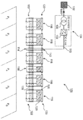
도 1은 충전 스테이션의 실시예를 도시한 도면.
도 2는 충전 단자, 보조 전류 단자 및 공급 단자의 보다 상세한 실시예를 도시한 도면.
도 3은 각각 3개의 다양한 차량 등급에 대한 3개의 상이한 충전 전류 프로파일을 포함한 그래프를 도시한 도면.
도 4는 충전 스테이션의 도 1에 대한 대안적인 실시예를 도시한 도면.The invention is illustrated below by way of example by way of example embodiments with reference to the accompanying drawings.
1 shows an embodiment of a charging station.
2 is a view showing a more detailed embodiment of a charging terminal, an auxiliary current terminal and a supply terminal.
3 shows a graph including three different charging current profiles for each of three different vehicle classes.
4 shows an alternative embodiment to FIG. 1 of a charging station.
도 1은 그리드 접속점(NAP)을 통해 전력 공급 그리드(102)에 연결된 충전 스테이션(100)을 도시한다. 전기 차량을 충전하기 위한 전력을 공급 그리드(102)로부터 인출하기 위해, 공급 장치(104)가 제공된다. 공급 장치(104)는 적어도 하나의 변압기(106) 및 변압기의 후방에 연결된 정류기 유닛(108)을 포함한다. 변압기(106)는 그리드 접속점(NAP)을 통해 직접 공급 그리드(102)에 연결되고, 제 1 AC 전압, 특히 그리드 전압을 정류기 유닛(108)에 적합한 제 2 AC 전압으로 변환한다. 구체적인 예로서, 이를 위해 도 1에 중전압 변압기가 도시되며, 상기 변압기는 20kV의 그리드 전압을 400V AC 전압으로 강압시킨다. 도시된 정류기 유닛(108)은 제 2 AC 전압으로부터 DC 전압 출력부에서 DC 전압을 생성하여 공급 그리드로부터 인출된 전력을 제공할 수 있다. 이로써 공급 장치(104)는 특히 전력 공급 그리드(102)에 접속을 위해서는 물론 충전 스테이션에 전력을 공급하기 위해 제공된다.1 shows a charging
도 1에 도시된 충전 스테이션(100)은 5개의 충전 단자(116), 공급 단자(114) 및 보조 전류 단자(118)를 더 포함하며, 이들은 간단하게 단자라고도 할 수 있다. 전술한 단자의 상세한 설명은 도 2의 설명에서 이어진다.The charging
구체적인 예에서, 충전 스테이션(100)의 단자들(114, 1116, 118)은 주차 공간(P1 내지 P6)에 나란히 배치된다. 이로써, 충전을 위해 주차 공간(P1- P6)에 주차될 수 있는 복수의 전기 차량이 충전될 수 있다. 주차 공간은 특히 예시적인 것으로 이해되어야 하고, 충전할 차량의 수를 6대로 제한하려는 것이 아니며, 오히려 기본적으로 도시된 충전 스테이션에서는 10대의 차량이 충전될 수 있다.In a specific example, the
공급 장치(104)에 의해 제공되는 전력을 DC 전압의 형태로 단자에 전달하기 위해, 공급 단자(114)가 제공된다. 이를 위해, 공급 단자는 메인 공급 라인(110)을 통해 정류기 유닛(108)에 전기적으로 연결된다. 메인 공급 라인(110)과의 전기적 연결을 형성하기 위해, 메인 공급 입력부(112)가 공급 단자(114)에 설치된다. 따라서 메인 공급 입력부(112)를 통해 공급 장치(104)로부터 전력이 인출될 수 있다. 이러한 방식으로 인출된 전력은 복수의 공급 라인(130)을 통해 다른 단자(116, 118)로 분배된다. 공급 단자(114)는 공급 장치로부터 전력을 수신하여 충전 단자(116) 및 필요 시 보조 전류 단자(118)로 전달하기 위한 것이다.In order to transfer the power provided by the
충전 스테이션(100)은 공급 단자 외에 적어도 하나의 전기 차량을 각각 충전하기 위한 복수의 충전 단자(116)를 갖는다.The charging
이 경우 각각의 충전 단자는 공급 입력부(120)와 충전 출력부(122)를 포함한다. 공급 입력부에서 단자들을 서로 연결할 수 있는 접속부들이 공급 입력부(120)에 제공됨으로써, 공급 입력부(120)는 공급 장치(104)로부터 전력을 인출하도록 구성된다. 도 1은 이 경우, 예를 들어 공급 단자(114)와 관련해서, 좌측에 2개의 충전 단자(116)가 배치되고 우측에 3개의 충전 단자 및 보조 전류 단자(118)가 배치된 것을 도시한다. 모든 단자는 각각의 공급 입력부(120)에서 공급 라인(130)을 통해 서로 전기적으로 연결된다. 도시된 예에서, 2개의 인접한 단자 사이에 공급 라인(130)의 각각의 섹션이 존재하여, 버스 바 또는 버스 라인의 경우에 통상적인 바와 같이, 하나의 연속하는 긴 공급 라인은 없다. 충전 단자는 공급 라인(130)을 통해 공급 단자(114)로부터 전달된 전력을 직접 인출할 수 있다. 그러나 충전 스테이션 내에 단자들의 배치에 따라, 충전 단자(116) 및 보조 전류 단자(118)는 공급 단자(114)의 전달된 전력을 다른 단자를 통해 간접적으로도 인출할 수 있다. 이러한 경우에, 공급 입력부들은 또한 인접한 단자를 위한 공급 출력부로도 간주될 수 있다.In this case, each charging terminal includes a
공급 입력부(120) 외에, 하나 이상의 충전 접속부를 갖는 충전 출력부(122)가 각각의 충전 단자(116)에 추가로 제공되며, 상기 충전 접속부는 접속된 각각의 전기 차량을 충전하기 위한 각각의 충전 전류를 출력하는데 이용된다. 도 2에서, 예를 들어 2대의 전기 차량은 5개의 충전 단자(116) 중 각각 하나의 충전 단자의 2개의 충전 출력부에 접속될 수 있다.In addition to the
초퍼 또는 DC-DC 변환기 당 각각 하나의 초퍼 전류를 생성하기 위해, 적어도 하나의 DC 초퍼(126)가 공급 입력부(120)와 충전 출력부(122) 사이에 각각의 충전 단자(116)마다 배치된다. 이와 같이 생성된 전류는, 충전 단자들 중 하나의 충전 단자의 충전 출력부(122)에 접속된 전기 차량을 충전하는데 이용된다.To generate one chopper current per chopper or DC-DC converter, at least one
추가 단자로서 보조 전류 단자가 충전 스테이션에 제공된다. 이러한 보조 전류 단자는, 전기 차량을 충전하기 위한 추가 전류를 생성하여 제공하는데 이용된다. 상기 보조 충전 단자는 전기 차량을 충전하기 위한 충전 출력부에 충전 접속부를 갖지 않는다. 충전 단자가 과도하게 이용되면, 예를 들어 추가 전류가 제공된다. 예를 들어, 전기 차량의 전류 요구가 단자가 생성할 수 있는 최대 전류를 초과하면, 과도한 이용이 발생할 수 있다. 구체적인 예는, 차량이 400A의 충전 전류를 요구하지만, 충전 단자는 최대 100A만을 제공할 수 있는 경우이다. 따라서 보조 전류 단자가 하나 이상의 추가 보조 전류, 특히 초퍼 전류를 생성하기 위해 제공되어, 이들 전류는 적어도 하나의 충전 단자에 제공될 수 있고, 이 경우 보조 전류 단자 자체는 충전 출력부를 갖지 않는다.As an additional terminal, an auxiliary current terminal is provided to the charging station. This auxiliary current terminal is used to generate and provide additional current for charging an electric vehicle. The auxiliary charging terminal does not have a charging connection to a charging output for charging an electric vehicle. If the charging terminal is used excessively, for example, additional current is provided. For example, if the current demand of the electric vehicle exceeds the maximum current that the terminal can generate, excessive use may occur. A specific example is a case where the vehicle requires a charging current of 400A, but the charging terminal can only provide up to 100A. Thus, auxiliary current terminals are provided to generate one or more additional auxiliary currents, particularly chopper currents, so that these currents can be provided to at least one charging terminal, in which case the auxiliary current terminal itself does not have a charging output.
특히 도 1에 도시된 충전 스테이션(100)에서 알 수 있는 것은, 충전 단자의 충전 출력부들(122)이 교환 접속부에서 전기 교환 라인(128)을 통해 서로 연결되므로, 생성된 초퍼 전류는 서로 교환될 수 있다는 점이다. 마찬가지로, 공급 단자(114) 및 보조 전류 단자(118)는 교환 라인(128)을 통해 출력 측에서 충전 단자(116)에 전기적으로 연결되는 것이 제공된다. 예를 들어, 주차 공간(P1)에 주차된 전기 차량은 다른 충전 단자 또는 보조 전류 단자로부터 DC 초퍼에 의해 적어도 부분적으로 생성된 충전 전류를 인출할 수 있다.Particularly, it can be seen from the charging
도 2는 도 1의 충전 단자(116), 보조 전류 단자(118) 또는 공급 단자(114)에 대응하는 충전 단자(A), 보조 전류 단자(B) 및 공급 단자(C)의 보다 상세한 실시예를 도시한다.2 is a more detailed embodiment of the charging
충전 단자(A)는 공급 입력부(200) 및 충전 출력부(202)를 갖는다. 공급 입력부(200)에는, 예를 들어 플러그 커넥터로서 형성될 수 있는 2개의 접속 수단(220)이 배치된다. 따라서 임의의 다른 충전 단자, 보조 전류 단자 또는 공급 단자가 이들 접속 수단에 접속될 수 있으므로, 이들 단자의 공급 입력부들은 서로 연결될 수 있다.The charging terminal A has a
각각의 충전 단자(A)는 2개의 DC 초퍼(226)를 가지며, 상기 초퍼들은 공급 입력부(200)와 충전 출력부(202) 사이에 서로 병렬로 배치되고, 충전 출력부에 배치된 각각의 횡방향 라인(QL1, QL2)에 각각 초퍼 전류(IS1 또는 IS2)를 인가한다. 각각의 DC 초퍼(226)에는 정확히 하나의 충전 접속부(222)가 할당되고, 각각의 DC 초퍼에 횡방향 라인(QL1, QL2)이 할당된다. 따라서 n개의 DC 초퍼에서 n개의 횡방향 라인은, DC 초퍼를 충전 접속부에 연결하는데 이용된다. 충전 단자(A) 내에 2개의 DC 초퍼가 존재함으로써, 단자는 2개의 횡방향 라인(QL1, QL2) 및 2개의 충전 접속부(222)로 구성된다.Each charging terminal A has two
충전 단자(A)의 경우에 추가로 제 1 및 제 2 연결 영역이 화살표들(204 및 206)로 표시되며, 상기 연결 영역은 각각 복수의, 특히 동일한 수의 교환 접속부(224)를 갖는다. 단자들은 이들 교환 접속부에서 실질적으로 병렬 교환 라인(228)을 통해 연결될 수 있으며, 상기 교환 라인들은 도 2에 점선으로 도시된다.In the case of the charging terminal A, the first and second connection areas are further indicated by
하나의 연결 영역(204, 206)의 각각의 교환 접속부(224)를 다른 연결 영역(206, 204)의 각각의 교환 접속부에 전기적으로 연결하기 위해, 연결 영역들 중 하나의 연결 영역의 각각의 교환 접속부에 대해 또한 단자 내에 라인(LL1, LL2, LL3)이 제공되므로, 하나의 연결 영역의 m개의 교환 접속부에 m개의 종방향 라인이 제공된다. 종방향 라인은 특히 전기적으로 서로 병렬이다. 이를 위해, 충전 단자(A)의 특정 설계는 예를 들어 연결 영역(206)에 3개의 교환 접속부를 갖고, 이로써 3개의 종방향 라인이 제공된다. 종방향 라인(LL1, LL2, LL3)은 2개의 연결 영역(204 및 206)을 연결한다.To electrically connect each
생성된 DC 초퍼 전류의 동적 교환이 가능하도록, 각각의 종방향 라인(LL1, LL2, LL3)은 각각 연결 노드를 통해 횡방향 라인(QL1, QL2) 중 적어도 하나에 직접 연결된다.To enable dynamic exchange of the generated DC chopper current, each longitudinal line LL 1 , LL 2 , LL 3 is directly connected to at least one of the transverse lines QL 1 , QL 2 through a connecting node, respectively. .
충전 전류들(IL1 또는 IL2)이 또한 충전 출력부들(222) 중 하나에서 임의로 생성될 수 있도록, 충전 단자 내에 제어 유닛에 의해 제어될 수 있는 복수의 제어 가능한 스위칭 수단이 존재한다. 각각의 충전 단자 자체가 제어 유닛을 가질 수 있거나 상위 레벨의 제어 유닛은 제어 가능한 스위칭 수단을 제어할 수 있다. 마찬가지로 각각의 충전 단자 내의 제어 유닛 및 상위 레벨의 제어 유닛으로 이루어진 혼합 형태가 구현될 수 있다. 그러나 이것은 도 2에 도시되지 않는다.There are a plurality of controllable switching means that can be controlled by the control unit in the charging terminal so that the charging currents I L1 or I L2 can also be randomly generated at one of the charging outputs 222. Each charging terminal itself may have a control unit or a higher level control unit may control controllable switching means. Likewise, a mixed form consisting of a control unit in each charging terminal and a higher level control unit can be implemented. However, this is not shown in FIG. 2.
도 2의 충전 단자 A에 3개의 교환 스위칭 수단(A1, A2 및 A3)은 제어 가능한 스위칭 수단으로서 도시되며, 상기 스위칭 수단들은, 인접한 충전 단자 또는 보조 전류 단자와 교환 수단을 통한 적어도 하나의 초퍼 전류의 교환을 제어하기 위해, 각각의 교환 접속부(224)에 전기적으로 연결된다. 제어 가능한 추가 스위칭 수단은 브리지 스위칭 수단(B1)이며, 상기 스위칭 수단은 충전 단자에서 2개의 DC 초퍼를, 이 경우 2개의 횡방향 라인(QL1 및 QL2)을 통해 전기적으로 서로 연결하여, 2개의 DC 초퍼(226)의 초퍼 전류(IS1 및 IS2)의 중첩이 제어될 수 있다. 마찬가지로, 충전 전류 lL1 또는 IL2의 출력을 제어하기 위해, 충전 스위칭 수단(C1 또는 C2)이 충전 접속부(222)에 배치된다.The three exchange switching means A1, A2 and A3 in the charging terminal A of Fig. 2 are shown as controllable switching means, which are at least one chopper current through the exchange means with adjacent charging terminals or auxiliary current terminals. To control the exchange of, it is electrically connected to each
따라서 도 2에 도시된 충전 단자(A)는 하나의 초퍼 전류(IS1 또는 IS2) 또는 복수의 초퍼 전류로부터 충전 전류(lL1 또는 IL2)를 형성할 수 있고, 교환 접속부를 통해 추가 초퍼 전류를 인출하거나 출력할 수 있다.Therefore, the charging terminal A shown in FIG. 2 can form a charging current (l L1 or I L2 ) from one chopper current (I S1 or I S2 ) or a plurality of chopper currents, and additional choppers through the exchange connection. Current can be drawn or output.
충전 단자 A와 달리, 보조 전류 단자 B에서 DC 초퍼(226)는, 모든 교환 라인(228)에 초퍼 전류(IS3)를 제공하기 위해, 모든 교환 접속부(224)에 연결된다. 따라서 보조 전류 단자는, 추가 전력을 출력하도록 준비된다. 초퍼 전류도 제어되어 출력될 수 있도록, 충전 단자 A와 유사하게, 3개의 교환 스위칭 수단(A1, A2 및 A3)이 보조 전류 단자 내에 제공된다. 이들은, 예를 들어 초퍼(226)가 보조 전류 단자에서 전류(IS3)를 생성하지 않는 경우, 인접한 단자의 초퍼 전류의 전달에도 이용될 수 있다.Unlike the charging terminal A, the
단자 A 및 B와 달리 공급 단자 C는 추가적인 메인 공급 입력부(212)를 가지며, 2개의 공급 출력부(221)는 단자 A 및 B의 공급 입력부와 동일한 구조이다. 공급 출력부(221)는, 공급 장치로부터 인출된 전력을 충전 단자로 및 필요 시 적어도 하나의 보조 전류 단자로 전달하기 위해, 특히 모든 충전 단자로 전력을 전달하기 위해 이용된다.Unlike terminals A and B, the supply terminal C has an additional
또한, 단자 A 및 B와 유사하게 공급 단자 C도, 공급 단자를 통해 적어도 하나의 초퍼 전류를 전도할 수 있도록 적어도 하나의 연결 영역(208 또는 210)에서 인접한 각각의 충전 단자 및/또는 필요 시 보조 전류 단자와 연결되도록, 교환 접속부(224)를 갖는다.In addition, similar to terminals A and B, the supply terminal C is also provided with each charging terminal adjacent to at least one
단자 A, B 및 C의 공급 입력부/-출력부 및 교환 접속부는 실질적으로 동일한 구조를 갖는다. 충전 스테이션은 임의로, 일종의 케이스처럼, 단자 A, B 및/또는 C로 모듈식으로 구성될 수 있다. The supply input / output and exchange connection of terminals A, B and C have substantially the same structure. The charging station can optionally be modularly configured with terminals A, B and / or C, like some sort of case.
도 1 및 도 2를 참조하여, 본 발명은 특히 각각 하나 이상의 DC 초퍼를 갖는 충전 단자 및 보조 전류 단자에 대해 설명되었다. 이러한 설명 및 전술한 장점들은 또한 각각 하나 이상의 DC 초퍼 대신에 하나 이상의 초퍼 단자를 사용하는 변형예에도 유사하게 적용될 수 있다. 예를 들어 충전 단자(A 또는 116) 내에 2개의 DC 초퍼(226 및 126) 대신에 2개의 초퍼 단자가 제공될 수 있으며, 상기 초퍼 단자는 공급 장치(104)로부터 각각 초퍼 전류를 수신하여 초퍼 전류(IS1 또는 IS2)로서 제공한다. 이를 위해 각각의 초퍼 단자에 대해 공급 장치(104) 내에 DC 초퍼가 제공될 수 있을 뿐만 아니라, 도 1에 따른 공급 장치(104)에 대한 연결 라인이 제공될 수 있다. 하나의, 복수의 또는 모든 충전 단자(116)에는 DC 초퍼(126) 대신에 초퍼 단자가 제공될 수 있다. 보조 전류 단자(118) 또는 임의의 추가 보조 전류 단자에도 동일하게 적용된다.1 and 2, the present invention has been particularly described for a charging terminal and an auxiliary current terminal each having one or more DC choppers. These descriptions and the aforementioned advantages can also be similarly applied to variations in which one or more chopper terminals are used instead of one or more DC choppers, respectively. For example, two chopper terminals may be provided in the charging terminal A or 116 instead of the two
예시를 위해, 도 4는 도 1에 대한 충전 스테이션의 대안적인 실시예를 도시한다. 명료함을 위해 동일하거나 유사한 요소에 대해 동일한 참조 번호가 사용된다. 도 4의 충전 스테이션(400)은 가장 오른쪽에 도시된 충전 단자(416)가 2개의 DC 초퍼(126) 대신에 2개의 초퍼 단자(427)를 갖는다는 점에서 도 1의 충전 스테이션(100)과 다르다. 초퍼 단자(427)는 각각의 개별 라인(410)을 통해 각각의 초퍼 전류를 수신하며, 상기 개별 라인은 공급 장치(404) 내의 DC 초퍼(126)에 각각 접속된다. 이로써 초퍼 단자(427)는 실질적으로, 2개의 DC 초퍼(126) 중 하나에 의해서만 생성된 하나의 초퍼 전류만을 제공한다. 여기에서 제공은 또한 횡방향 라인(QL1 또는 QL2)에서 수행되며, 상기 라인의 추가 상호 접속은 도 2에 더 상세하게 설명되어 있다. 이것은 또한 도 4의 변형예에도 유사하게 적용될 수 있다. 대안으로서 2개의 개별 라인(410)은 공급 단자(114)를 통해서 및 공급 입력부(120)를 통해서도 안내될 수 있다.For illustrative purposes, FIG. 4 shows an alternative embodiment of the charging station for FIG. 1. The same reference numbers are used for the same or similar elements for clarity. The charging
도 3은 각각 3개의 상이한 차량 등급(AM1, AM2 및 AM3)에 대한 3개의 상이한 충전 전류 프로파일(I1, I2 및 I3)을 퍼센트로 나타낸 그래프를 도시한다. 충전 스테이션의 이용률은 세로 좌표에 퍼센트로 표시되며, 이 예에서 충전 단자는 100% 이용률일 경우 100A의 충전 전류를 출력할 수 있으며, 이는 차량 등급 AM1의 최대 전류에 해당한다. 가로 좌표에 시간 t이 분 단위로 표시된다.FIG. 3 shows a graph showing the percentage of three different charging current profiles I 1 , I 2 and I 3 for three different vehicle classes AM1, AM2 and AM3, respectively. The utilization rate of the charging station is expressed as a percentage in the ordinate, and in this example, the charging terminal can output a charging current of 100A at 100% utilization, which corresponds to the maximum current of vehicle class AM1. The time t is displayed in minutes in the abscissa.
3개의 전류 특성 곡선(I1, I2 및 I3)의 프로파일은 매우 상이하며, 3개의 특성 곡선 각각은 상이한 차량 등급(AM1, AM2 또는 AM3)의 전류 특성 곡선에 해당한다. 차량 등급 AM3에 대해, 이것은 차량 등급 AM1 및 AM2보다 약 2배 높은 충전 전압을 필요로 하는 것에 주목해야 한다. 차량 유형 AM3에 대해 도 3에 도시된 처음의 400% 충전 전류는 차량 등급 AM1과 관련해서, 대략 800% 충전 전력에 대응한다. 마찬가지로, 완전 충전을 기준으로 80%의 충전 상태를 나타내는 충전 상태(State of Charge)의 80%-SOC 지점은 매우 상이한 시점에 달성된다. 차량 등급 AM1은 예를 들어 소형차 등급에 해당하고, 자동차 등급 AM2는 프리미엄 등급에 해당하고, 등급 AM3은 수퍼 스포츠카 등급에 해당할 수 있다. 자동차 등급 또는 차량 유형에 따라 충전 특성 곡선 또는 전류 특성 곡선(I1, I2 및 I3)은 다른 프로파일을 갖는다. 2개의 초퍼는 병렬로(중복 전류) 또는 직렬로(중복 전압) 작동할 수 있다.The profiles of the three current characteristic curves I 1 , I 2 and I 3 are very different, and each of the three characteristic curves corresponds to a current characteristic curve of a different vehicle class (AM1, AM2 or AM3). It should be noted that for vehicle class AM3, this requires a charge voltage approximately twice as high as vehicle classes AM1 and AM2. For vehicle type AM3, the first 400% charge current shown in FIG. 3 corresponds to approximately 800% charge power, with respect to vehicle class AM1. Likewise, the 80% -SOC point of the State of Charge, representing 80% charge state based on full charge, is achieved at very different time points. The vehicle class AM1 may correspond to, for example, a small car class, the car class AM2 to a premium class, and the class AM3 to a super sports car class. Depending on the vehicle class or vehicle type, the charging characteristic curve or the current characteristic curves I 1 , I 2 and I 3 have different profiles. The two choppers can operate in parallel (redundant current) or in series (redundant voltage).
자동차 등급 AM1의 경우, 예를 들어 약 20 분 동안 100A의 비교적 일정한 충전 전류가 필요하므로, DC 초퍼를 갖는 충전 단자가 100% 이용된다. 이 경우 100A를 공급할 수 있는 초퍼로 이미 충분했다. 그러나 그와 달리 프리미엄 차량이나 스포츠카에서는 하나의 충전 단자만으로는 차량 유형을 충전하는데 필요한 충전 전류를 제공할 수 없었다. DC 초퍼가 수퍼 스포츠카를 위한 예를 들어 400A의 충전 전류에 대해 설계될 필요가 없도록 하기 위해, 제안된 충전 단자는 제 1 충전 영역(A01)에서 수퍼 스포츠카를 충전할 수 있도록 인접한 단자를 통해 DC 초퍼 전류를 인출할 수 있다. 충전 영역(A02)에서 수퍼 스포츠카의 전류 요구는 비교적 신속하게 감소한다. 필요하지 않은 DC 초퍼는 차량의 전류 요구에 따라 - 이것이 더 이상 필요하지 않은 경우 - 다시 제어 유닛에 의해 해제되고 또는 꺼지거나 전환될 수 있다.For automotive class AM1, a relatively constant charging current of 100A is required, for example, for about 20 minutes, so a charging terminal with a DC chopper is used 100%. In this case, a chopper capable of supplying 100A was already sufficient. However, in a premium vehicle or a sports car, however, only one charging terminal could not provide the charging current required to charge the vehicle type. To ensure that the DC chopper does not have to be designed for a charging current of 400 A for a super sports car, the proposed charging terminal is a DC chopper through an adjacent terminal to allow charging the super sports car in the first charging area A01. Current can be drawn. In the charging area A02, the current demand of the super sports car decreases relatively quickly. The DC chopper which is not needed can be released by the control unit or turned off or switched again according to the current demand of the vehicle-if this is no longer needed.
수퍼 스포츠카의 특정 예와 관련하여, 충전 스테이션은 동시에 7개 또는 8개의 DC 초퍼로 최대 300% 이용률까지 처음 거의 7분 내에 각각 약 50A에서 수퍼 스포츠카를 충전할 수 있었다. 예를 들어 전술한 수퍼 스포츠카는 두 배 높은 충전 전압을 필요로 하므로, DC 초퍼 당 약 100A 대신 약 50A만 공급될 수 있기 때문에, 이러한 다수가 필요하다. 300% 내지 200%에서 6개 또는 5개의 DC 초퍼만이 필요하고, 200%부터 여전히 4개 또는 3개의 DC 초퍼가 필요할 것이며, 22.5분 후에 작업 영역(A03)에서는 스포츠카를 완전히 충전하기 위해, 2개 또는 1개의 DC 초퍼만이 필요하다.With regard to a particular example of a super sports car, the charging station was able to charge the super sports car at about 50A each in the first almost 7 minutes, up to 300% utilization with 7 or 8 DC choppers simultaneously. For example, the above-mentioned super sports car requires a double higher charging voltage, and thus, a large number is necessary because only about 50 A can be supplied instead of about 100 A per DC chopper. From 300% to 200%, only 6 or 5 DC choppers will be needed, from 200% you will still need 4 or 3 DC choppers, and after 22.5 minutes the working area (A03) will fully charge the sports car, 2 Only one or one DC chopper is required.
Claims (14)
- 충전 스테이션에 전력 공급을 위한, 특히 전력 공급 그리드(102)에 접속을 위한 공급 장치(104), 및
- 각각의 경우에 적어도 하나의 전기 차량을 충전하기 위한 복수의 충전 단자(116)
를 포함하고, 각각의 충전 단자는,
- 공급 장치로부터 전력을 인출하기 위한 공급 입력부(120),
- 접속된 각각의 전기 차량을 충전하기 위한 각각의 충전 전류를 출력하기 위한 하나 이상의 충전 접속부를 갖는 충전 출력부(122), 및
- 공급 장치의 전력으로부터 각각의 초퍼 전류를 생성하기 위해, 상기 공급 입력부와 상기 충전 출력부 사이에 배치된 적어도 하나의 DC 초퍼(126), 또는 대안으로서 상기 충전 단자 외부에서 DC 초퍼에 의해 생성된 초퍼 전류, 특히 공급 장치에서 생성된 초퍼 전류를 제공하기 위해, 상기 공급 입력부와 상기 공급 출력부 사이에 배치된 적어도 하나의 초퍼 단자 - 어느 경우든,
- 각각의 충전 전류(IL1, IL2)는 하나의 초퍼 전류 또는 복수의 초퍼 전류(IS1, IS2, IS3)로부터 형성되며,
- 충전 단자들이 전기 교환 라인(128)을 통해 교환 접속부에서 서로 연결되어, 초퍼 전류가 서로 교환될 수 있음 -
를 포함하는 것인, 충전 스테이션.A charging station (100) for charging a plurality of electric vehicles, especially electric vehicles,
-A supply 104 for powering the charging station, in particular for connection to the power supply grid 102, and
-A plurality of charging terminals 116 for charging at least one electric vehicle in each case
Including, each charging terminal,
-Supply input unit 120 for drawing power from the supply device,
-A charging output unit 122 having one or more charging connections for outputting respective charging currents for charging each connected electric vehicle, and
-At least one DC chopper 126 disposed between the supply input and the charging output, or alternatively generated by a DC chopper outside the charging terminal, to generate each chopper current from the power of the supply device At least one chopper terminal disposed between the supply input and the supply output to provide a chopper current, especially a chopper current generated in a supply device-in any case,
-Each charging current (I L1 , I L2 ) is formed from one chopper current or a plurality of chopper currents (I S1 , I S2 , I S3 ),
-The charging terminals are connected to each other at the exchange connection through the electric exchange line 128, so that the chopper currents can be exchanged with each other-
It includes, a charging station.
상기 충전 스테이션(100)은, 하나 이상의 추가 초퍼 전류를 적어도 하나의 충전 단자에 제공하기 위해, 하나 이상의 추가 초퍼 전류를 제공하기 위한, 특히 생성하기 위한 적어도 하나의 보조 전류 단자(118)를 가지며, 상기 보조 전류 단자 자체에는 충전 출력부가 없고, 각각의 보조 전류 단자는,
- 충전 단자의 공급 입력부에 대응하며 상기 공급 장치로부터 전력을 인출하기 위한 공급 입력부,
- 충전 단자의 교환 접속부에 대응하며 적어도 하나의 충전 단자에 초퍼 전류를 전송하기 위한 적어도 하나의 교환 접속부, 및
- 상기 공급 장치의 전력으로부터 각각의 초퍼 전류를 생성하기 위해, 상기 공급 입력부와 상기 적어도 하나의 교환 접속부 사이에 배치되며 상기 충전 단자의 상기 또는 하나의 DC 초퍼에 대응하는 적어도 하나의 DC 초퍼, 또는 대안으로서 상기 보조 전류 단자 외부에서 DC 초퍼에 의해 생성된 초퍼 전류, 특히 공급 장치에서 생성된 초퍼 전류를 제공하기 위해, 상기 공급 입력부와 상기 적어도 하나의 교환 접속부 사이에 배치되며 상기 충전 단자의 상기 또는 하나의 초퍼 단자에 대응하는 적어도 하나의 초퍼 단자
를 포함하고,
- 특히 모든 교환 라인에 초퍼 전류를 제공하기 위해, 상기 보조 전류 단자의 DC 초퍼 또는 초퍼 단자는 상기 보조 전류 단자의 모든 교환 접속부에 연결되는 것을 특징으로 하는 충전 스테이션.According to claim 1,
The charging station 100 has at least one auxiliary current terminal 118 for providing, in particular generating, one or more additional chopper currents, in order to provide one or more additional chopper currents to the at least one charging terminal, The auxiliary current terminal itself has no charging output, and each auxiliary current terminal has:
-A supply input for drawing power from the supply and corresponding to the supply input for the charging terminal,
-At least one exchange connection for transmitting a chopper current to at least one charge terminal, corresponding to the exchange connection of the charge terminal, and
-At least one DC chopper disposed between the supply input and the at least one exchange connection and corresponding to the or one DC chopper of the charging terminal, to generate each chopper current from the power of the supply; or As an alternative, to provide a chopper current generated by a DC chopper outside the auxiliary current terminal, in particular a chopper current generated by a supply device, disposed between the supply input and the at least one exchange connection and the or At least one chopper terminal corresponding to one chopper terminal
Including,
Charging station characterized in that the DC chopper or chopper terminal of the auxiliary current terminal is connected to all the exchange connections of the auxiliary current terminal, in particular to provide chopper current to all of the exchange lines.
상기 충전 스테이션(100)은 상기 공급 장치(104)로부터 전력을 수신하여 상기 충전 단자로 전달하기 위한 적어도 하나의 공급 단자(114)를 가지며, 각각의 공급 단자는,
- 상기 공급 장치로부터 전력을 인출하기 위해, 메인 공급 라인(110)을 통해 상기 공급 장치에 연결된 메인 공급 입력부(112), 및
- 상기 공급 장치로부터 인출된 전력을 상기 충전 단자 및 적용되는 경우에 상기 적어도 하나의 보조 전류 단자에 전달하기 위한, 특히 모든 충전 단자에 전력을 전달하기 위한, 적어도 하나의 공급 출력부
를 포함하고, 바람직하게는,
- 적어도 하나의 초퍼 전류를 상기 공급 단자를 통해 라우팅할 수 있도록 하기 위해, 적어도 하나의 연결 영역에서 각각의 인접한 충전 단자 및/또는 가능하게는 보조 전류 단자에 연결되도록, 상기 충전 단자 및 적용되는 경우에 상기 적어도 하나의 보조 전류 단자의 교환 접속부에 대응하는 교환 접속부가 상기 공급 단자의 제 1 및 제 2 연결 영역에 존재하는 것을 특징으로 하는 충전 스테이션.The method according to claim 1 or 2,
The charging station 100 has at least one supply terminal 114 for receiving power from the supply device 104 and transferring it to the charging terminal, each supply terminal,
-A main supply input unit 112 connected to the supply device through a main supply line 110 to draw power from the supply device, and
-At least one supply output for transferring power drawn from the supply to the charging terminal and, if applicable, to the at least one auxiliary current terminal, in particular for transferring power to all charging terminals
And preferably,
The charging terminal and, if applicable, to be connected to each adjacent charging terminal and / or possibly an auxiliary current terminal in at least one connection area, so as to be able to route at least one chopper current through the supply terminal In the charging station, characterized in that the exchange connection portion corresponding to the exchange connection portion of the at least one auxiliary current terminal is present in the first and second connection regions of the supply terminal.
- 상기 충전 단자, 가능하게는 상기 적어도 하나의 보조 전류 단자는 동일한 구조의 공급 입력부(200)를 가지므로, 각각 2개의 공급 입력부가 서로 연결됨으로써, 각각의 공급 전류 또는 그것의 일부가 하나의 공급 입력부로부터 인접한 공급 입력부로 전달될 수 있어서, 각각의 충전 단자 및 적용가능한 경우에 각각의 보조 전류 단자는 인접한 충전 단자, 보조 전류 단자, 또는 공급 단자로부터 자신의 공급 전류를 수신하는 것, 및/또는
- 상기 충전 단자, 가능하게는 상기 보조 전류 단자, 및 상기 공급 단자 중에 각각 선택적으로 2개의 단자를 교환 가능하게 서로 연결하기 위해, 상기 공급 입력부 및/또는 상기 교환 접속부는 각각 동일한 구조의 접속 수단(220, 224), 특히 플러그 커넥터를 가지며, 특히 이로써 서로 연결된 모든 상기 충전 단자, 가능하게는 상기 보조 전류 단자, 및 상기 공급 단자는 전체적으로 모듈식 구조를 형성하고, 특히 상기 공급 단자는 이것을 위해 구성된 교환 접속부 및/또는 공급 출력부를 갖는 것을 특징으로 하는 충전 스테이션.The method according to any one of claims 1 to 3,
-Since the charging terminal, possibly the at least one auxiliary current terminal has a supply input 200 having the same structure, each of the two supply inputs is connected to each other, so that each supply current or a part thereof is supplied as one. Can be transferred from an input to an adjacent supply input, such that each charging terminal and, where applicable, each auxiliary current terminal receives its supply current from an adjacent charging terminal, auxiliary current terminal, or supply terminal, and / or
-The supply input and / or the exchange connection are each connected by means of the same structure in order to selectively connect the two terminals of the charging terminal, possibly the auxiliary current terminal, and the supply terminal to each other interchangeably 220, 224), in particular having a plug connector, in particular all of said charging terminals connected to each other, possibly said auxiliary current terminals, and said supply terminals as a whole form a modular structure, in particular said supply terminals being configured for this exchange Charging station characterized by having a connection and / or a supply output.
- 각각의 충전 단자는 하기 목록 중 적어도 하나의 제어 가능한 스위칭 수단을 갖는 것을 특징으로 하는 충전 스테이션.
- 교환 수단을 통한, 인접한 충전 단자 또는 보조 전류 단자와의 적어도 하나의 초퍼 전류의 교환을 제어하기 위해, 각각의 교환 접속부에 전기적으로 연결된 교환 스위칭 수단(A1, A2, A3);
- 상기 충전 접속부로의 충전 전류의 출력을 제어하기 위해, 각각의 충전 접속부에 전기적으로 연결된 충전 스위칭 수단(C1, C2); 및
- 2개의 DC 초퍼 또는 초퍼 단자의 초퍼 전류의 중첩을 제어하기 위해, 충전 단자 내의 상기 2개의 DC 초퍼 또는 초퍼 단자에, 특히 2개의 횡방향 라인을 통해 전기적으로 연결된 브리지 스위칭 수단(B1).The method according to any one of claims 1 to 4,
-Each charging terminal has at least one controllable switching means in the following list.
-Switching switching means (A1, A2, A3) electrically connected to each exchange connection to control the exchange of at least one chopper current with an adjacent charging terminal or an auxiliary current terminal through the switching means;
-Charging switching means (C1, C2) electrically connected to each charging connection to control the output of the charging current to said charging connection; And
Bridge switching means (B1) electrically connected to the two DC choppers or chopper terminals in the charging terminal, in particular via two transverse lines, to control the superposition of the chopper currents of the two DC choppers or chopper terminals.
- 각각의 충전 단자는 각각 복수의, 특히 동일한 수의 교환 접속부(224)를 갖는 제 1 및 제 2 연결 영역(204, 206)을 가지며,
- 하나의 연결 영역(204)의 각각의 교환 접속부를 다른 연결 영역(206)의 각각의 교환 접속부에 전기적으로 연결하기 위해, 하나의 연결 영역의 각각의 교환 접속부마다 종방향 라인(LL1, LL2, LL3)이 제공되어, 하나의 연결 영역의 m개의 교환 접속부에 m개의 종방향 라인이 제공되고, 특히 상기 종방향 라인은 전기적으로 서로 병렬로 연장되고,
- 각각의 DC 초퍼(226) 또는 초퍼 단자에는 충전 접속부(222)가 할당되고, 각각의 DC 초퍼 또는 각각의 초퍼 단자마다 횡방향 라인(QL1, QL2)이 제공되어, 상기 DC 초퍼 또는 상기 초퍼 단자가 상기 충전 접속부에 연결될 수 있고, 따라서 n개의 DC 초퍼 또는 n개의 초퍼 단자에 n개의 횡방향 라인이 제공되며,
- 각각의 종방향 라인은 연결 노드를 통해 상기 횡방향 라인 중 적어도 하나에 직접 연결되고, 및/또는
- 각각의 경우에 2개의 횡방향 라인을 전기적으로 연결하기 위해, 정확히 n-1개의 브리지 스위칭 수단이 제공되고, 및/또는
- 상기 충전 스위칭 수단에 대한 각각의 횡방향 라인은 추가 스위칭 수단을 갖지 않고, 및/또는
- 각각의 충전 단자에는 횡방향 라인보다 종방향 라인이 하나 더 제공되므로, m = n + 1이고,
- 상기 충전 단자 내의 종방향 라인은,
- 각각의 연결 노드를 통해 2개의 횡방향 라인에 직접 연결되고, 2개의 연결 노드 사이의 상기 브리지 스위칭 수단 중 하나를 갖거나, 또는
- 연결 노드를 통해 하나의 횡방향 라인에만 연결되고, 상기 충전 단자 내에 브리지 스위칭 수단을 갖지 않는 것을 특징으로 하는 충전 스테이션.The method according to any one of claims 1 to 5,
-Each charging terminal has first and second connecting regions 204 and 206, each having a plurality of, in particular, the same number of exchange connections 224,
-Longitudinal lines LL1, LL2 for each exchange connection in one connection area to electrically connect each exchange connection in one connection area 204 to each exchange connection in the other connection area 206, LL3) is provided so that m longitudinal lines are provided at m exchange connections in one connection area, in particular the longitudinal lines are electrically extended in parallel to each other,
-Each DC chopper 226 or chopper terminal is assigned a charging connection 222, and each DC chopper or each chopper terminal is provided with lateral lines QL1, QL2, thereby providing the DC chopper or the chopper terminal. Can be connected to the charging connection, thus providing n transverse lines to n DC choppers or n chopper terminals,
-Each longitudinal line is directly connected to at least one of said transverse lines via a connecting node, and / or
-In order to electrically connect the two transverse lines in each case, exactly n-1 bridge switching means are provided, and / or
Each transverse line to said charging switching means has no additional switching means, and / or
-Since each charging terminal is provided with one more longitudinal line than the transverse line, m = n + 1,
-The longitudinal line in the charging terminal,
-Directly connected to two transverse lines through each connecting node, having one of the bridge switching means between the two connecting nodes, or
-A charging station, which is connected to only one transverse line through a connecting node and does not have a bridge switching means within said charging terminal.
- 충전 단자의 충전 전류가 하나의 초퍼 전류 또는 복수의 초퍼 전류로부터 형성될 수 있는 방식으로, 상기 충전 단자(116) 및/또는 상기 보조 전류 단자(118)를 제어하도록 준비된 적어도 하나의 제어 유닛이 제공되고,
- 충전 전류는, 동일한 충전 단자의 하나 이상의 DC 초퍼 또는 초퍼 단자의 초퍼 전류로부터 및/또는 하나 이상의 다른 충전 단자의 하나 이상의 DC 초퍼 또는 초퍼 단자의 초퍼 전류로부터 및/또는 복수의 충전 단자의 하나 이상의 DC 초퍼 및 하나 이상의 초퍼 단자의 초퍼 전류로부터 형성되는 것을 특징으로 하는 충전 스테이션.The method according to any one of claims 1 to 6,
At least one control unit prepared to control the charging terminal 116 and / or the auxiliary current terminal 118 in such a way that the charging current of the charging terminal can be formed from a single chopper current or a plurality of chopper currents Provided,
-The charging current is from one or more DC choppers or chopper currents of the same charging terminal and / or from one or more DC choppers or chopper currents of one or more other charging terminals and / or one or more of a plurality of charging terminals Charging station characterized in that it is formed from the chopper current of the DC chopper and one or more chopper terminals.
- 상기 충전 스테이션(100)은,
- 충전될 전기 차량이 접속된 충전 단자의 적어도 하나의 교환 스위칭 수단이 차단될 수 있음으로써, 적어도 하나의 초퍼 전류가 적어도 하나의 인접한 충전 단자로부터 인출되어 충전할 전기 차량을 위한 충전 전류가 생성될 수 있는 방식으로, 및/또는
- 상기 전기 차량이 접속된 상기 충전 단자의 적어도 하나의 브리지 스위칭 수단이 차단될 수 있음으로써, 상기 충전 전류를 생성하기 위해 상기 충전 단자 내에 배치된 복수의 DC 초퍼 또는 초퍼 단자의 복수의 초퍼 전류가 결합될 수 있는 방식으로, 및/또는
- 적어도 하나의 인접한 또는 추가의 충전 단자 및/또는 인접한 또는 추가의 보조 전류 단자의 적어도 하나의 교환 스위칭 수단이 차단될 수 있음으로써, 상기 충전 전류를 생성하기 위해 인접한 또는 추가의 충전 단자 또는 보조 전류 단자로부터 적어도 하나의 초퍼 전류가 인출되어 결합되는 방식으로, 및/또는
- 적어도 하나의 인접한 또는 추가의 충전 단자의 적어도 하나의 브리지 스위칭 수단이 차단될 수 있음으로써, 상기 충전 전류를 생성하기 위해 적어도 하나의 교환 라인을 통해 상기 인접한 충전 단자 내에 배치된 복수의 DC 초퍼 또는 초퍼 단자로부터 적어도 하나의 초퍼 전류가 인출될 수 있는 방식으로,
특히 하나의 또는 적어도 하나의 제어 유닛을 통해 구동 가능하도록 구성되는 것을 특징으로 하는 충전 스테이션.The method according to any one of claims 1 to 7,
-The charging station 100,
-At least one exchange switching means of the charging terminal to which the electric vehicle to be charged is connected can be cut off, so that at least one chopper current is drawn from at least one adjacent charging terminal to generate a charging current for the electric vehicle to be charged In a way that is possible, and / or
-At least one bridge switching means of the charging terminal to which the electric vehicle is connected can be cut off, so that a plurality of DC choppers or a plurality of chopper currents of the chopper terminals disposed in the charging terminal to generate the charging current In a manner that can be combined, and / or
-At least one exchange switching means of at least one adjacent or additional charging terminal and / or adjacent or additional auxiliary current terminal can be blocked, thereby generating adjacent or additional charging terminal or auxiliary current to generate said charging current In such a way that at least one chopper current is drawn from the terminal and coupled, and / or
-At least one bridge switching means of at least one adjacent or additional charging terminal can be cut off, so that a plurality of DC choppers arranged in said adjacent charging terminal via at least one exchange line to generate said charging current or In such a way that at least one chopper current can be drawn from the chopper terminal,
In particular, the charging station characterized in that it is configured to be operable through one or at least one control unit.
- 적어도 하나의 교환 스위칭 수단과 적어도 하나의 브리지 스위칭 수단은,
- 충전 전류의 생성을 위해 거기에서 적어도 하나의 추가 초퍼 전류와 결합되도록 하기 위해,
- 특히 제 2 횡방향 라인에 접속된 전기 차량을 충전하기 위해,
- 제 1 충전 단자 또는 제 1 보조 전류 단자의, DC 초퍼 또는 초퍼 단자의, 초퍼 전류가 제 1 종방향 라인 및 적어도 하나의 교환 스위칭 수단을 통해 제 2 충전 단자로 흐를 수 있도록,
- 상기 제 2 충전 단자에서의 초퍼 전류가 제 1 연결 노드 및 제 1 횡방향 라인을 통해 제 2 종방향 라인으로 흐를 수 있도록, 그리고
- 상기 초퍼 전류가 제 2 연결 노드, 상기 적어도 하나의 브리지 스위칭 수단, 및 제 3 연결 노드를 통해 상기 제 2 충전 단자의 제 2 횡방향 라인으로 흐를 수 있도록,
상호 접속될 수 있는 것을 특징으로 하는 충전 스테이션.The method according to any one of claims 1 to 8,
-At least one exchange switching means and at least one bridge switching means,
-To be combined with at least one additional chopper current there to generate a charging current,
-In particular to charge the electric vehicle connected to the second transverse line,
-So that the chopper current, of the DC chopper or chopper terminal of the first charging terminal or the first auxiliary current terminal, can flow to the second charging terminal through the first longitudinal line and at least one switching switching means,
-So that the chopper current at the second charging terminal can flow through the first connecting node and the first transverse line to the second longitudinal line, and
-So that the chopper current can flow through the second connecting node, the at least one bridge switching means, and the third connecting node to the second transverse line of the second charging terminal,
Charging station characterized in that it can be interconnected.
- 상기 충전 스테이션은, 충전 전류가 적어도 3개의 초퍼 전류, 바람직하게는 적어도 5개의 초퍼 전류, 특히 적어도 7개의 초퍼 전류로부터 형성될 수 있도록, 제어 가능한 스위칭 수단이 스위칭될 수 있는 방식으로,
- 특히 하나의 또는 적어도 하나의 제어 유닛을 통해 구동될 수 있도록 구성되는 것을 특징으로 하는 충전 스테이션.The method according to any one of claims 1 to 9,
The charging station in such a way that the controllable switching means can be switched so that the charging current can be formed from at least three chopper currents, preferably at least five chopper currents, in particular at least seven chopper currents,
-A charging station, characterized in that it is configured to be particularly operable via one or at least one control unit.
- 제어 유닛은 충전 전류의 생성, 특히 충전 접속부에서 제공되는 초퍼 전류의 수를 하기 목록에서 선택된 제어 기준에 따라 제어할 수 있는 것을 특징으로 하는 충전 스테이션.
- 상기 충전 접속부에 접속된 전기 차량의 유형,
- 상기 충전 접속부에 접속된 전기 차량의 저장 상태,
- 상기 접속된 전기 차량의 저장 상태에 따른 전류 요구(current request),
- 상기 접속된 전기 차량의 전류 요구,
- 상기 충전 접속부에 접속된 전기 차량을 충전하기 위해 사용자에 의해 지정된 충전 희망(charging wish), 및
- 충전 전류를 생성하기 위한 결합될 초퍼 전류를 생성 또는 제공하기 위해, 이용 가능한 DC 초퍼 및/또는 초퍼 단자의 수.The method according to any one of claims 1 to 10,
-A charging station characterized in that the control unit can control the generation of the charging current, in particular the number of chopper currents provided at the charging connection according to the control criteria selected from the list below.
-The type of electric vehicle connected to the charging connection,
-The storage state of the electric vehicle connected to the charging connection,
-Current request according to the storage state of the connected electric vehicle (current request),
-The current demand of the connected electric vehicle,
-A charging wish specified by a user to charge an electric vehicle connected to said charging connection, and
-The number of DC chopper and / or chopper terminals available to generate or provide a chopper current to be combined to generate a charging current.
- 상기 충전 스테이션의 공급 장치를 통해 상기 충전 스테이션에 전력을 공급하는 단계; 및
- 각각의 경우에 상기 충전 스테이션의 복수의 충전 단자 중 하나를 사용하여 적어도 하나의 전기 차량을 충전하는 단계
를 포함하고, 상기 적어도 하나의 전기 차량을 충전하는 단계는,
- 상기 충전 단자의 공급 입력부에서 상기 공급 장치로부터 전력을 인출하는 단계, 및
- 접속된 전기 차량을 충전하기 위한 각각의 충전 전류를 하나 이상의 충전 접속부를 갖는 충전 출력부에서 출력하는 단계
를 포함하고, 상기 전기 차량은 상기 충전 전류가 출력되는 상기 충전 접속부 중 하나에 접속되고,
- 상기 공급 입력부와 상기 충전 출력부 사이에 배치된 적어도 하나의 DC 초퍼가 상기 공급 장치의 전력으로부터 각각의 초퍼 전류를 생성하거나, 상기 공급 입력부와 상기 충전 출력부 사이에 배치된 적어도 하나의 초퍼 단자가 각각의 경우에 각각의 충전 단자 외부에서 각각의 DC 초퍼에 의해 생성된 초퍼 전류, 특히 상기 공급 장치에서 생성된 초퍼 전류를 제공하고, 어느 경우든
- 상기 충전 전류는 하나의 초퍼 전류 또는 복수의 초퍼 전류로부터 형성되고,
- 상기 충전 단자는 교환 접속부에서 전기 교환 라인을 통해 서로 연결되며, 선택적으로
- 상기 전기 교환 라인을 통해 초퍼 전류를 서로 교환하는 것인,
충전 스테이션을 사용하여 복수의 전기 차량을 충전하기 위한 방법.A method for charging a plurality of electric vehicles, particularly electric vehicles, using a charging station,
-Supplying power to the charging station through a supply device of the charging station; And
-Charging at least one electric vehicle in one of the plurality of charging terminals of the charging station in each case
Including, charging the at least one electric vehicle,
-Drawing power from the supply device at the supply input of the charging terminal, and
-Outputting each charging current for charging the connected electric vehicle at a charging output unit having at least one charging connection unit
Including, the electric vehicle is connected to one of the charging connection unit is the charging current is output,
-At least one DC chopper disposed between the supply input and the charging output generates each chopper current from the power of the supply, or at least one chopper terminal arranged between the supply input and the charging output Provides a chopper current generated by each DC chopper outside each charging terminal in each case, particularly a chopper current generated by the supply, in either case
-The charging current is formed from one chopper current or a plurality of chopper currents,
-The charging terminals are connected to each other through an electric exchange line at the exchange connection, and optionally
-To exchange chopper currents with each other through the electric exchange line,
Method for charging a plurality of electric vehicles using a charging station.
- 충전될 전기 차량이 접속된 충전 단자의 적어도 하나의 교환 스위칭 수단이 차단되고, 이로 인해 적어도 하나의 인접한 충전 단자로부터 적어도 하나의 초퍼 전류가 인출되고, 따라서 충전할 전기 차량을 위한 충전 전류가 생성되고, 및/또는
- 상기 전기 차량이 접속된 상기 충전 단자의 적어도 하나의 브리지 스위칭 수단은 차단되고, 이로 인해 상기 충전 전류를 생성하기 위해 상기 충전 단자 내에 배치된 복수의 DC 초퍼 또는 초퍼 단자의 복수의 초퍼 전류가 결합 또는 중첩되고, 및/또는
- 적어도 하나의 인접한 또는 추가의 충전 단자 및/또는 인접한 또는 추가의 보조 전류 단자의 적어도 하나의 교환 스위칭 수단이 차단되고, 이로 인해 상기 충전 전류를 생성하기 위해 인접한 또는 추가의 충전 단자 또는 보조 전류 단자로부터 적어도 하나의 초퍼 전류가 인출되어 결합 또는 중첩되고, 및/또는
- 적어도 하나의 인접한 또는 추가의 충전 단자의 적어도 하나의 브리지 스위칭 수단이 차단되고, 이로 인해 상기 충전 전류를 생성하기 위해 적어도 하나의 교환 라인을 통해 인접한 충전 단자 내에 배치된 복수의 DC 초퍼 또는 초퍼 단자로부터 적어도 하나의 초퍼 전류가 인출되는 것을 특징으로 하는 충전 스테이션을 사용하여 복수의 전기 차량을 충전하기 위한 방법.The method of claim 12 or 13,
-At least one exchange switching means of the charging terminal to which the electric vehicle to be charged is connected is cut off, thereby drawing at least one chopper current from at least one adjacent charging terminal, thus generating a charging current for the electric vehicle to be charged And / or
-At least one bridge switching means of the charging terminal to which the electric vehicle is connected is cut off, whereby a plurality of DC choppers disposed in the charging terminal or a plurality of chopper currents of the chopper terminals are coupled to generate the charging current Or overlap, and / or
-At least one switching means of switching of at least one adjacent or additional charging terminal and / or adjacent or additional auxiliary current terminal is blocked, thereby causing the adjacent or additional charging terminal or auxiliary current terminal to generate said charging current From which at least one chopper current is drawn to combine or overlap, and / or
-At least one bridge switching means of at least one adjacent or additional charging terminal is cut off, whereby a plurality of DC choppers or chopper terminals disposed in adjacent charging terminals via at least one exchange line to generate said charging current A method for charging a plurality of electric vehicles using a charging station, characterized in that at least one chopper current is drawn from.
Applications Claiming Priority (3)
| Application Number | Priority Date | Filing Date | Title |
|---|---|---|---|
| DE102017116887.7A DE102017116887A1 (en) | 2017-07-26 | 2017-07-26 | Charging station with dynamic charging current distribution |
| DE102017116887.7 | 2017-07-26 | ||
| PCT/EP2018/070293 WO2019020747A1 (en) | 2017-07-26 | 2018-07-26 | Charging station having dynamic charging current distribution |
Publications (1)
| Publication Number | Publication Date |
|---|---|
| KR20200032173A true KR20200032173A (en) | 2020-03-25 |
Family
ID=63042024
Family Applications (1)
| Application Number | Title | Priority Date | Filing Date |
|---|---|---|---|
| KR1020207005352A KR20200032173A (en) | 2017-07-26 | 2018-07-26 | Charging station with dynamic charging current distribution |
Country Status (10)
| Country | Link |
|---|---|
| US (1) | US11264798B2 (en) |
| EP (1) | EP3659232B1 (en) |
| JP (1) | JP7042326B2 (en) |
| KR (1) | KR20200032173A (en) |
| CN (1) | CN110999009B (en) |
| BR (1) | BR112020001498A2 (en) |
| CA (1) | CA3069797C (en) |
| DE (1) | DE102017116887A1 (en) |
| RU (1) | RU2730914C1 (en) |
| WO (1) | WO2019020747A1 (en) |
Cited By (1)
| Publication number | Priority date | Publication date | Assignee | Title |
|---|---|---|---|---|
| WO2022164153A1 (en) * | 2021-01-26 | 2022-08-04 | 주식회사 에프이씨 | Charging location selectable-type electric vehicle charging method and system |
Families Citing this family (10)
| Publication number | Priority date | Publication date | Assignee | Title |
|---|---|---|---|---|
| DE102017116886A1 (en) * | 2017-07-26 | 2019-01-31 | Wobben Properties Gmbh | Charging station with dynamic charging current distribution |
| DE102018212740A1 (en) * | 2018-07-31 | 2020-02-06 | Ads-Tec Gmbh | Charging station for electric cars |
| CN112217406A (en) * | 2019-07-11 | 2021-01-12 | 台达电子工业股份有限公司 | Power supply device applied to solid-state transformer framework and three-phase power supply system |
| DE102019217784A1 (en) * | 2019-11-19 | 2021-05-20 | Volkswagen Aktiengesellschaft | Charging infrastructure for charging a motor vehicle |
| FR3110787B1 (en) | 2020-05-20 | 2022-07-08 | Ineo Urban Transp Solutions | CHARGING STATION FOR FLEETS OF ELECTRIC VEHICLES |
| DE102020209653A1 (en) | 2020-07-30 | 2022-02-03 | Volkswagen Aktiengesellschaft | Electrical charging system for charging an electrical accumulator |
| FR3113205A1 (en) * | 2020-08-03 | 2022-02-04 | Hager-Electro Sas | Electrical distribution circuit for vehicle parking lot |
| DE102020134458A1 (en) * | 2020-12-21 | 2022-06-23 | innogy eMobility Solutions GmbH | Arrangement for integration into a charging device for at least one electric vehicle |
| US20220410755A1 (en) * | 2021-06-25 | 2022-12-29 | Zoox, Inc. | Fleet charging station architecture |
| EP4112362A1 (en) * | 2021-06-29 | 2023-01-04 | Ekoenergetyka - Polska Sp. z o.o. | Terminal for charging electric vehicles with electrochemical energy storage |
Family Cites Families (37)
| Publication number | Priority date | Publication date | Assignee | Title |
|---|---|---|---|---|
| JP3214044B2 (en) * | 1992-03-27 | 2001-10-02 | 株式会社明電舎 | Charging device |
| US5926004A (en) * | 1997-10-10 | 1999-07-20 | Schott Power Systems Incorporated | Method and apparatus for charging one or more electric vehicles |
| US7256516B2 (en) * | 2000-06-14 | 2007-08-14 | Aerovironment Inc. | Battery charging system and method |
| JP2007323843A (en) * | 2006-05-30 | 2007-12-13 | Ebara Ballard Corp | Operation method of fuel cell and fuel cell system |
| JP2008199752A (en) * | 2007-02-09 | 2008-08-28 | Kyushu Electric Power Co Inc | Charger |
| CN101483350A (en) | 2009-02-28 | 2009-07-15 | 上海中上汽车科技有限公司 | Capacitor or power cell traction type electric vehicle charging base station system |
| NL2004279C2 (en) | 2010-02-22 | 2011-08-23 | Epyon B V | System, device and method for exchanging energy with an electric vehicle. |
| NL2004350C2 (en) | 2010-03-05 | 2011-09-06 | Epyon B V | System, devices and method for charging a battery of an electric vehicle. |
| KR101009485B1 (en) | 2010-04-20 | 2011-01-19 | (주)모던텍 | Universal charging device |
| JP5647057B2 (en) | 2010-05-19 | 2014-12-24 | 株式会社日立製作所 | Charging apparatus, charging control unit, and charging control method |
| NL2004746C2 (en) * | 2010-05-19 | 2011-11-22 | Epyon B V | Charging system for electric vehicles. |
| KR20110137675A (en) | 2010-06-17 | 2011-12-23 | (주)시그넷시스템 | Charge station |
| NL2005026C2 (en) | 2010-07-05 | 2012-01-09 | Epyon B V | Charger for a battery, plurality of coupled chargers and method of operating. |
| US8952656B2 (en) | 2011-02-04 | 2015-02-10 | Atieva, Inc. | Battery charging station |
| US9065356B2 (en) * | 2011-02-28 | 2015-06-23 | Hitachi, Ltd. | Electric power converter |
| DE102011079430A1 (en) * | 2011-07-19 | 2013-01-24 | Siemens Aktiengesellschaft | DC charging station for charging multiple energy storage devices |
| JP2013027236A (en) * | 2011-07-25 | 2013-02-04 | Toyota Motor Corp | Battery charging system and vehicle charging system |
| US8810198B2 (en) | 2011-09-02 | 2014-08-19 | Tesla Motors, Inc. | Multiport vehicle DC charging system with variable power distribution according to power distribution rules |
| JP2013110870A (en) | 2011-11-21 | 2013-06-06 | Panasonic Corp | Power converter |
| WO2013084999A1 (en) * | 2011-12-08 | 2013-06-13 | 株式会社エネルギー応用技術研究所 | Rapid charging power supply system |
| NL2008058C2 (en) | 2011-12-29 | 2013-07-03 | Epyon B V | Method, system and charger for charging a battery of an electric vehicle. |
| JP5723811B2 (en) | 2012-03-13 | 2015-05-27 | 株式会社トライネット | Electric vehicle charging device and charging system |
| WO2013137501A1 (en) * | 2012-03-14 | 2013-09-19 | (주)시그넷시스템 | Charging station |
| DE102012218738A1 (en) * | 2012-10-15 | 2014-04-17 | Siemens Aktiengesellschaft | Charging system as satellite charging system for electric car, has charging portions to charge batteries through power supply terminal and direct current regulators, where one regulator is optionally connected to two charging portions |
| EP3782846A1 (en) | 2013-11-06 | 2021-02-24 | ABB Schweiz AG | Charger for electric vehicles with distributed power converter arbitration |
| CN104810894B (en) | 2015-05-08 | 2017-04-05 | 山东鲁能智能技术有限公司 | A kind of split type direct-current charging post of electric automobile, system and method |
| JP6548262B2 (en) | 2015-12-25 | 2019-07-24 | ニチコン株式会社 | Charging system for electric vehicles |
| CN105449791A (en) | 2016-01-07 | 2016-03-30 | 山东泰开自动化有限公司 | DC intelligent charging pile for electric automobiles |
| CN105480110B (en) | 2016-01-12 | 2019-02-19 | 沈阳工业大学 | Intelligent charging spot and intelligent charging method |
| DE102016103011A1 (en) | 2016-02-22 | 2017-08-24 | Dr. Ing. H.C. F. Porsche Aktiengesellschaft | Method and device for operating charging stations |
| CN106042952B (en) * | 2016-05-23 | 2018-04-13 | 国网山东省电力公司莱芜供电公司 | A kind of more power section parallel connection quick charging systems and method |
| CN106564399B (en) | 2016-11-11 | 2018-05-15 | 深圳市沃特玛电池有限公司 | Charging station |
| DE102017116886A1 (en) * | 2017-07-26 | 2019-01-31 | Wobben Properties Gmbh | Charging station with dynamic charging current distribution |
| RU2701510C1 (en) * | 2017-10-06 | 2019-09-27 | Др. Инж. х.к. Ф. Порше АГ | Configuration of converter for electric charging station and corresponding electric charging station |
| CN109638933A (en) * | 2017-10-06 | 2019-04-16 | 保时捷股份公司 | Being galvanically isolated in the power electronic equipment at charging station or power-up station |
| CN109638935A (en) * | 2017-10-06 | 2019-04-16 | 保时捷股份公司 | Use of two DC/DC adjusters in the power electronic equipment at charging station or power-up station |
| DE102018100988A1 (en) * | 2018-01-17 | 2019-07-18 | Dr. Ing. H.C. F. Porsche Aktiengesellschaft | Supply device for a motor vehicle |
-
2017
- 2017-07-26 DE DE102017116887.7A patent/DE102017116887A1/en not_active Withdrawn
-
2018
- 2018-07-26 EP EP18746679.2A patent/EP3659232B1/en active Active
- 2018-07-26 CN CN201880050260.6A patent/CN110999009B/en active Active
- 2018-07-26 WO PCT/EP2018/070293 patent/WO2019020747A1/en unknown
- 2018-07-26 JP JP2020502300A patent/JP7042326B2/en active Active
- 2018-07-26 RU RU2020108008A patent/RU2730914C1/en active
- 2018-07-26 BR BR112020001498-2A patent/BR112020001498A2/en not_active Application Discontinuation
- 2018-07-26 US US16/633,924 patent/US11264798B2/en active Active
- 2018-07-26 CA CA3069797A patent/CA3069797C/en active Active
- 2018-07-26 KR KR1020207005352A patent/KR20200032173A/en not_active Application Discontinuation
Cited By (1)
| Publication number | Priority date | Publication date | Assignee | Title |
|---|---|---|---|---|
| WO2022164153A1 (en) * | 2021-01-26 | 2022-08-04 | 주식회사 에프이씨 | Charging location selectable-type electric vehicle charging method and system |
Also Published As
| Publication number | Publication date |
|---|---|
| CA3069797C (en) | 2022-06-21 |
| US11264798B2 (en) | 2022-03-01 |
| BR112020001498A2 (en) | 2020-07-21 |
| EP3659232A1 (en) | 2020-06-03 |
| WO2019020747A1 (en) | 2019-01-31 |
| EP3659232B1 (en) | 2024-03-06 |
| JP2020527323A (en) | 2020-09-03 |
| CA3069797A1 (en) | 2019-01-31 |
| EP3659232C0 (en) | 2024-03-06 |
| CN110999009B (en) | 2023-12-15 |
| CN110999009A (en) | 2020-04-10 |
| US20210129701A1 (en) | 2021-05-06 |
| RU2730914C1 (en) | 2020-08-26 |
| DE102017116887A1 (en) | 2019-01-31 |
| JP7042326B2 (en) | 2022-03-25 |
Similar Documents
| Publication | Publication Date | Title |
|---|---|---|
| KR20200032173A (en) | Charging station with dynamic charging current distribution | |
| KR20200028000A (en) | Charging station with dynamic charging current distribution | |
| NL2004350C2 (en) | System, devices and method for charging a battery of an electric vehicle. | |
| CN105322787A (en) | Three port dc-dc converter | |
| KR101729483B1 (en) | A variable capacity charging system for vehicles | |
| US11305661B2 (en) | Modular charging station for electric automobiles | |
| CN108233421A (en) | Photovoltaic generating system and photovoltaic electric power distribution | |
| CN106114270B (en) | A kind of charging system and charge control method | |
| US11351885B2 (en) | Charging infrastructure unit, and charging infrastructure having a charging power option | |
| KR20160086512A (en) | Integration type power conversion apparatus for vehicle | |
| KR20180046525A (en) | Electric vehicle charging device for providing wire and wireless charging means | |
| CN217804367U (en) | Charging pile system and charging system of battery replacement station | |
| CN115742800A (en) | Charging device, charging stack and charging system | |
| US11130413B2 (en) | Arrangement of multiple electrical machines for a vehicle for improving the energy supply while reducing installation space and weight | |
| CN220163713U (en) | Self-adaptive power supply equipment and electric automobile | |
| JP7454436B2 (en) | storage battery board | |
| JP2024017253A (en) | vehicle charging device | |
| CN117922347A (en) | Power distribution device, charging equipment, energy storage equipment and charging system | |
| CN116674430A (en) | Self-adaptive power supply equipment, electric automobile and electric quantity balancing method | |
| CN114123157A (en) | Electric pile is filled in flexible interconnection of distributing type and energy storage integration | |
| CN116811599A (en) | Buck-boost system based on motor controller and motor and new energy vehicle | |
| WO2023222256A1 (en) | Charging apparatus and method for providing a charging power | |
| KR20240043239A (en) | Power control unit for electric vehicle | |
| CN116805811A (en) | Charging equipment and power distribution unit |
Legal Events
| Date | Code | Title | Description |
|---|---|---|---|
| A201 | Request for examination | ||
| E902 | Notification of reason for refusal | ||
| E601 | Decision to refuse application |