KR20200026349A - A apparatus for drying the coated film - Google Patents
A apparatus for drying the coated film Download PDFInfo
- Publication number
- KR20200026349A KR20200026349A KR1020180101928A KR20180101928A KR20200026349A KR 20200026349 A KR20200026349 A KR 20200026349A KR 1020180101928 A KR1020180101928 A KR 1020180101928A KR 20180101928 A KR20180101928 A KR 20180101928A KR 20200026349 A KR20200026349 A KR 20200026349A
- Authority
- KR
- South Korea
- Prior art keywords
- hot air
- unit
- moving
- sliding
- heating air
- Prior art date
Links
Images


Classifications
-
- B—PERFORMING OPERATIONS; TRANSPORTING
- B05—SPRAYING OR ATOMISING IN GENERAL; APPLYING FLUENT MATERIALS TO SURFACES, IN GENERAL
- B05D—PROCESSES FOR APPLYING FLUENT MATERIALS TO SURFACES, IN GENERAL
- B05D3/00—Pretreatment of surfaces to which liquids or other fluent materials are to be applied; After-treatment of applied coatings, e.g. intermediate treating of an applied coating preparatory to subsequent applications of liquids or other fluent materials
- B05D3/04—Pretreatment of surfaces to which liquids or other fluent materials are to be applied; After-treatment of applied coatings, e.g. intermediate treating of an applied coating preparatory to subsequent applications of liquids or other fluent materials by exposure to gases
- B05D3/0406—Pretreatment of surfaces to which liquids or other fluent materials are to be applied; After-treatment of applied coatings, e.g. intermediate treating of an applied coating preparatory to subsequent applications of liquids or other fluent materials by exposure to gases the gas being air
- B05D3/0413—Heating with air
-
- F—MECHANICAL ENGINEERING; LIGHTING; HEATING; WEAPONS; BLASTING
- F26—DRYING
- F26B—DRYING SOLID MATERIALS OR OBJECTS BY REMOVING LIQUID THEREFROM
- F26B21/00—Arrangements or duct systems, e.g. in combination with pallet boxes, for supplying and controlling air or gases for drying solid materials or objects
- F26B21/004—Nozzle assemblies; Air knives; Air distributors; Blow boxes
-
- F—MECHANICAL ENGINEERING; LIGHTING; HEATING; WEAPONS; BLASTING
- F26—DRYING
- F26B—DRYING SOLID MATERIALS OR OBJECTS BY REMOVING LIQUID THEREFROM
- F26B3/00—Drying solid materials or objects by processes involving the application of heat
- F26B3/02—Drying solid materials or objects by processes involving the application of heat by convection, i.e. heat being conveyed from a heat source to the materials or objects to be dried by a gas or vapour, e.g. air
- F26B3/04—Drying solid materials or objects by processes involving the application of heat by convection, i.e. heat being conveyed from a heat source to the materials or objects to be dried by a gas or vapour, e.g. air the gas or vapour circulating over or surrounding the materials or objects to be dried
Landscapes
- Engineering & Computer Science (AREA)
- Mechanical Engineering (AREA)
- General Engineering & Computer Science (AREA)
- Life Sciences & Earth Sciences (AREA)
- Microbiology (AREA)
- Drying Of Solid Materials (AREA)
Abstract
Description
본 발명은 코팅필름 건조장치에 관한 것으로서, 보다 상세하게는 분리형 열풍 조사부를 슬라이딩 결합부를 통하여 전후진 가능하게 설치하여 상기 열풍 조사부 내부에 대한 유지보수 작업이 용이한 코팅필름 건조장치에 관한 것이다. The present invention relates to a coating film drying apparatus, and more particularly, to a coating film drying apparatus that can be installed back and forth through a sliding coupling unit to enable the maintenance work for the inside of the hot air irradiation unit.
일반적으로 코팅필름 건조기는 필름의 표면에 일정 두께로 코팅된 코팅액을 고온의 열풍으로 건조시켜 코팅액을 경화시키는 것으로, 이러한 건조기는 덕트로 유입된 열풍이 필름과 마주하도록 배치된 노즐을 통해 분사됨으로써 일정 속도로 통과하는 필름의 표면에 코팅된 코팅액을 건조하여 일정한 막을 형성시키는 것이다. In general, the coating film dryer dries the coating liquid by drying the coating liquid coated with a predetermined thickness on the surface of the film with a high temperature hot air, and the dryer is sprayed through a nozzle disposed so that the hot air flowing into the duct faces the film. The coating liquid coated on the surface of the film passing at a speed is dried to form a constant film.
이때, 다수의 노즐을 통해 분사되는 열풍의 세기가 일정하게 유지되어야만 다수의 노즐을 지나가는 필름에 굴곡이 발생하는 것을 방지할 수 있고, 필름과 다수의 노즐 사이의 거리를 일정하게 유지하여 코팅액을 균일하게 건조시킬 수 있다. At this time, the intensity of the hot air sprayed through the plurality of nozzles must be kept constant to prevent the occurrence of bending in the film passing through the plurality of nozzles, and to maintain a constant distance between the film and the plurality of nozzles to uniform the coating liquid. Can be dried.
한편, 장기간 코팅필름 건조기를 사용함에 따라 열풍에 포함된 이물질 또는 건조 과정에서 발생된 이물질이 노즐 내부에 축적될 수 있다. 이러한 이물질은 노즐을 통한 열풍의 분사시에 함께 분사되어 필름에 도포된 코팅액에 흡착되기 때문에 코팅필름의 불량 발생의 원인이 된다. On the other hand, as the coating film dryer is used for a long time, foreign matters included in the hot air or foreign matters generated during the drying process may accumulate inside the nozzle. These foreign matters are sprayed together at the time of jet of hot air through the nozzle and are adsorbed to the coating liquid applied to the film, thereby causing a defect of the coating film.
그러나 종래의 코팅필름 건조기는 열풍을 분사하는 노즐이 폐쇄형으로 이루어지기 때문에 노즐 내부를 청소하기 어려운 문제점이 있다. However, the conventional coating film dryer has a problem that it is difficult to clean the inside of the nozzle because the nozzle for spraying hot air is made of a closed type.
본 발명이 해결하고자 하는 기술적 과제는 분리형 열풍 조사부를 슬라이딩 결합부를 통하여 전후진 가능하게 설치하여 상기 열풍 조사부 내부에 대한 유지보수 작업이 용이한 코팅필름 건조장치를 제공하는 것이다. The technical problem to be solved by the present invention is to provide a coating film drying apparatus that is easy to maintain and maintain the inside of the hot air irradiator by installing the detachable hot air irradiator forward and backward through the sliding coupling.
전술한 기술적 과제를 해결하기 위한 본 발명에 따른 코팅필름 건조장치는, 코팅액이 도포되어 있는 코팅필름을 수평 방향으로 이송하는 본체; 상기 본체의 상부에 분리 가능하게 결합되어 상기 본체에 의하여 수평 이동하는 상기 코팅 필름에 균일하게 열풍을 조사하는 열풍 조사부; 상기 열풍 조사부를 상기 본체의 측부에 회동가능하게 결합시키는 힌지 결합부; 상기 힌지 결합부의 반대편에 설치되며, 상기 열풍 조사부를 상기 힌지 결합부를 회전 중심으로 하여 회동시키는 회전 동력 제공부; 상기 열풍 조사부의 상부에 결합되어 설치되며, 상기 열풍 조사부에 가열 공기를 공급하는 가열공기 공급부; 상기 열풍 조사부와 가열공기 공급부 사이에 설치되며, 상기 열풍 조사부를 상기 가열공기 공급부에 대하여 상대적으로 슬라이딩 이동가능하게 결합시키는 슬라이딩 결합부;를 포함한다. Coating film drying apparatus according to the present invention for solving the above technical problem, the main body for transporting the coating film is coated with a coating liquid in the horizontal direction; A hot air irradiator coupled to the upper part of the main body to irradiate hot air uniformly to the coating film horizontally moved by the main body; A hinge coupler configured to rotatably couple the hot air irradiator to a side of the main body; A rotational power providing unit installed on an opposite side of the hinge coupling unit and configured to rotate the hot air irradiating unit with the hinge coupling unit as the rotation center; A heating air supply unit coupled to an upper portion of the hot wind irradiator to supply heating air to the hot wind irradiator; And a sliding coupling part installed between the hot air irradiator and the heating air supply unit, and configured to relatively slidably couple the hot air irradiator to the heating air supply unit.
또한 본 발명에서 상기 열풍 조사부는, 상기 수평 이동 블럭에 결합되어 상기 수평 이동 블럭과 함께 슬라이딩 이동하는 이동판; 상기 이동판과 결합되어 차단된 열풍 분사 공간을 형성하고, 다수개의 분사홀이 균일하게 배치되어 상기 코팅 필름 방향으로 균일하게 열풍을 조사하는 분사판; 상기 분사판의 일측 모서리 부분을 상기 이동판의 일측 모서리 부분에 힌지 결합시키는 힌지 결합부; 상기 힌지 결합부의 반대편에 설치되며, 상기 분사판을 상기 이동판에 결합된 상태에서 고정하는 고정부; 상기 이동판을 관통하여 형성되며, 상기 가열공기 결합부에 의하여 공급되는 가열공기과 통과하는 가열공기 통과공;을 포함하는 것이 바람직하다. In addition, the hot air irradiator in the present invention, the moving plate coupled to the horizontal moving block and the sliding movement with the horizontal moving block; A spray plate coupled to the moving plate to form a blocked hot wind spray space, and having a plurality of spray holes uniformly disposed to irradiate hot wind uniformly in the coating film direction; A hinge coupler configured to hingely couple one side edge portion of the jet plate to one side edge portion of the moving plate; A fixing part installed at an opposite side of the hinge coupler and fixing the jet plate in a state of being coupled to the moving plate; It is preferably formed through the moving plate, the heating air passing through the heating air supplied by the heating air coupling portion; passing through the air.
또한 본 발명에서 상기 가열공기 공급부에는, 상기 가열공기 통과공 방향으로 전후진 가능하게 설치되며, 상기 가열공기 공급부에서 공급되는 가열공기의 외부 유출을 방지하면서 상기 열풍 조사부 방향으로 가열공기를 안내하는 가열공기 안내부가 더 구비되는 것이 바람직하다. Further, in the present invention, the heating air supply unit is installed so as to be moved forward and backward in the direction of the heating air passing through, the heating to guide the heating air in the direction of the hot air irradiation unit while preventing the outflow of the heating air supplied from the heating air supply unit Preferably, the air guide portion is further provided.
또한 본 발명에서 상기 슬라이딩 결합부는, 상기 열풍 조사부 상부와 결합되어 상기 열풍 조사부를 일정 간격 슬라이딩 이동시키는 제1 슬라이딩 이동부와, 상기 제1 슬라이딩 이동부 상부와 결합되어 설치되며, 상기 제1 슬라이딩 이동부를 상기 가열공기 공급부에 대하여 상대적으로 슬라이딩 이동시키는 제2 슬라이딩 이동부를 포함하여 구성되는 것이 바람직하다. In addition, in the present invention, the sliding coupling unit is coupled to the upper portion of the hot air irradiating unit, the first sliding moving unit for sliding the hot air irradiating unit at regular intervals, and is installed in combination with the upper portion of the first sliding moving unit, the first sliding movement It is preferably configured to include a second sliding movement for sliding the portion relative to the heating air supply.
그리고 본 발명에서 상기 제1 슬라이딩 이동부는, 상기 제2 슬라이딩 이동부의 양 측면에 각각 설치되는 수평 이동가이드; 상기 열풍 조사부의 양 측면에 각각 설치되며, 상기 수평 이동가이드를 타고 수평 이동하는 수평 이동 블럭;을 포함하는 것이 바람직하다. And in the present invention, the first sliding movement unit, the horizontal movement guides respectively installed on both sides of the second sliding movement portion; It is preferably installed on both sides of the hot air irradiator, the horizontal moving block to move horizontally on the horizontal guide.
본 발명에 따른 코팅필름 건조장치에 의하면, 분리형 열풍 조사부를 슬라이딩 결합부를 통하여 전후진 가능하게 설치하여 상기 열풍 조사부 내부에 대한 유지보수 작업이 용이하며, 상기 분리형 열풍 조사부 자체도 노즐이 설치되는 하부를 상부와 분리할 수 있도록 하여 개별 노즐도 청소할 수 있는 장점이 있다. According to the coating film drying apparatus according to the present invention, by installing the detachable hot air irradiating unit forward and backward through the sliding coupling portion, the maintenance work on the hot air irradiating unit is easy, and the separable hot air irradiating unit itself has a lower portion where the nozzle is installed. The separation from the top has the advantage that individual nozzles can also be cleaned.
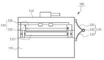
도 1은 본 발명의 일 실시예에 따른 코팅필름 건조장치의 구조를 도시하는 도면이다.
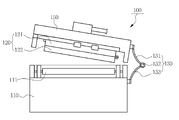
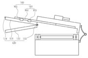
도 2 내지 4는 본 발명의 일 실시예에 따른 코팅필름 건조장치의 개방 과정을 도시하는 도면들이다.
도 5는 본 발명의 일 실시예에 따른 분사판의 구조를 도시하는 도면이다.
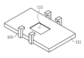
도 6은 본 발명의 일 실시예에 따른 이동판의 구조를 도시하는 도면이다.
도 7은 본 발명의 일 실시예에 따른 가열공기 공급부의 구성을 도시하는 도면이다. 1 is a view showing the structure of a coating film drying apparatus according to an embodiment of the present invention.
2 to 4 are views showing the opening process of the coating film drying apparatus according to an embodiment of the present invention.
5 is a view showing the structure of a jet plate according to an embodiment of the present invention.
6 is a view showing the structure of a moving plate according to an embodiment of the present invention.
7 is a view showing a configuration of a heating air supply unit according to an embodiment of the present invention.
이하에서는 첨부된 도면을 참조하여 본 발명의 구체적인 실시예를 상세하게 설명한다. Hereinafter, with reference to the accompanying drawings will be described in detail a specific embodiment of the present invention.
본 실시예에 따른 코팅필름 건조장치(100)는, 도 1 내지 4에 도시된 바와 같이, 본체(110), 열풍 조사부(120), 회동 결합부(130), 회전동력 제공부(도면에 미도시), 가열공기 공급부(150) 및 슬라이딩 결합부(160)를 포함하여 구성될 수 있다. Coating
먼저 상기 본체(110)는 코팅액이 도포되어 있는 코팅필름을 수평 방향으로 이송하는 구성요소이며, 본 실시예에 따른 코팅필름 건조장치(100)의 하부를 이룬다. 따라서 상기 본체(110)에는 상기 코팅필름을 일정한 속도로 수평이동시킬 수 있는 롤러 컨베이어(111) 등이 구비되며, 상기 열풍 조사부(120)와 결합하여 안정적인 건조 조건을 형성하기 위한 합체 구조를 가진다. First, the
다음으로 상기 열풍 조사부(120)는 도 2 내지 4에 도시된 바와 같이, 상기 본체(110)의 상부에 분리 가능하게 결합되어 상기 본체(110)에 의하여 수평 이동하는 상기 코팅 필름에 균일하게 열풍을 조사하는 구성요소이다. 즉, 상기 열풍 조사부(120)는 상기 회동 결합부(130)에 의하여 상기 본체(110)와 결합한 상태에서는 상기 본체(110)에 의하여 수평 이동하는 코팅필름에 열풍을 조사하여 코팅액을 건조시키고, 분리되어 개방된 상태에서는 열풍 조사부(120) 내부에 대한 유지보수 작업이 용이하도록 한다. Next, as illustrated in FIGS. 2 to 4, the
이를 위하여 본 실시예에서는 상기 열풍 조사부(120)를 구체적으로 도 4 내지 7에 도시된 바와 같이, 이동판(121), 분사판(122), 힌지 결합부(123), 고정부(124) 및 가열공기 통과공(125)을 포함하여 구성할 수 있다. 먼저 상기 이동판(121)은 후술하는 상기 수평 이동 블럭에 결합되어 상기 수평 이동 블럭과 함께 슬라이딩 이동하는 구성요소이다. 물론 상기 이동판(121)은 상기 분사판(122)과 분리 결합 가능하도록 설치되며, 상기 분사판(122)과 결합한 상태에서는 열풍 분사 공간을 형성한다. To this end, in the present embodiment, the
다음으로 상기 분사판(122)은 도 3, 4에 도시된 바아 같이, 상기 이동판과 결합되어 차단된 열풍 분사 공간(126)을 형성하고, 도 5에 도시된 바와 같이, 다수개의 분사홀(127)이 균일하게 배치되어 상기 코팅 필름 방향으로 균일하게 열풍을 조사하는 구성요소이다. 즉, 상기 분사판(122)은 상기 이동판(121)과 결합되어 함께 이동하며, 상기 이동판(121)과 결합한 상태에서 상기 열풍 분사 공간(126)으로 유입된 열풍을 모아서 상기 분사홀(127)을 통하여 균일하게 분사되도록 한다. Next, as illustrated in FIGS. 3 and 4, the
상기 다수개의 분사홀(127)은 도 5에 도시된 바와 같이, 상기 분사판(122)을 두께 방향으로 관통하여 형성되며, 균일한 분사를 위하여 상기 분사판(122)의 전면에 걸쳐서 일정한 간격을 가지도록 균일하게 배치된다. As illustrated in FIG. 5, the plurality of
필요에 따라서는 상기 분사판(122)을 다수개로 분할하여 구성할 수 있으며, 이렇게 상기 분사판(122)이 다수개로 분할되는 경우에는 상기 이동판(121)도 동일하게 분할되어 구성되어야 한다. If necessary, the
다음으로 상기 힌지 결합부(123)는 도 4에 도시된 바와 같이, 상기 분사판(122)의 일측 모서리 부분을 상기 이동판(121)의 일측 모서리 부분에 힌지 결합시키는 구성요소이다. 즉, 상기 힌지 결합부(123)에 의하여 상기 분사판(122)이 상기 이동판(121)에 회동가능하게 결합되는 것이며, 중량물인 상기 분사판(122)을 작업자가 용이하게 개방하거나 닫을 수 있는 것이다. Next, as shown in FIG. 4, the
다음으로 상기 고정부(124)는 도 4에 도시된 바와 같이, 상기 힌지 결합부(123)의 반대편에 설치되며, 상기 분사판(122)을 상기 이동판(121)에 결합된 상태에서 고정하는 구성요소이다. 즉, 상기 고정부(124)는 상기 힌지 결합부(123)에 의하여 회동하는 방식으로 개방가능한 상기 분사판(122)을 상기 이동판(121)에 밀착된 상태에서 안정적으로 고정하는 것이다. Next, as shown in FIG. 4, the
다음으로 상기 가열공기 통과공(125)은 도 6, 7에 도시된 바와 같이, 상기 이동판(121)을 관통하여 형성되며, 상기 가열공기 결합부(150)에 의하여 공급되는 가열공기가 통과하는 구성요소이다. 상기 가열공기 통과공(125)은 도 6에 도시된 바와 같이, 상기 이동판(121)의 중앙을 관통하여 비교적 큰 면적을 가지도록 형성되며, 상기 가열공기 공급부(150)에 의하여 상기 열풍 조사부(120)로 유입되는 모든 가열공기가 이동하는 통로이다. Next, as shown in FIGS. 6 and 7, the heated
다음으로 상기 회동 결합부(130)는 도 2 내지 4에 도시된 바와 같이, 상기 열풍 조사부(120)를 상기 본체(110)의 측부에 회동가능하게 결합시키는 구성요소이다. 즉, 상기 회동 결합부(130)에 의하여 상기 열풍 조사부(120) 및 이에 결합되어 있는 가열공기 공급부(150) 등이 함께 회동할 수 있는 것이다. Next, as shown in FIGS. 2 to 4, the
다음으로 상기 회전동력 제공부(도면에 미도시)는 상기 회동 결합부(130)의 반대편에 설치되며, 상기 열풍 조사부(120)를 상기 회동 결합부를 회전 중심으로 하여 회동시키는 구성요소이다. 상기 회전 동력 제공부는 실린더 등 다양한 구성을 가질 수 있으며, 작업자가 인력으로 개방하기 어려운 중량의 열풍 조사부(120) 및 가열공기 공급부(150)를 개방할 수 있도록 하는 것이다. Next, the rotational power providing unit (not shown) is installed on the opposite side of the
다음으로 상기 가열공기 공급부(150)는 도 2 내지 4에 도시된 바와 같이, 상기 열풍 조사부(120)의 상부에 결합되어 설치되며, 상기 열풍 조사부(120)에 가열 공기를 공급하는 구성요소이다. 즉, 상기 가열공기 공급부(150)는 외부에서 공급되는 가열공기를 상기 가열공기 통과공(125)을 통하여 상기 열풍 조사부(120)로 전달하는 것이며, 이와 동시에 상기 열풍 조사부(120)를 상기 슬라이딩 결합부(160)와 함께 슬라이딩 가능하게 결합시키는 것이다. Next, as shown in FIGS. 2 to 4, the heated
따라서 상기 가열공기 공급부(150)에는, 도 7에 도시된 바와 같이, 상기 가열공기 통과공(125) 방향으로 전후진 가능하게 설치되며, 상기 가열공기 공급부(150)에서 공급되는 가열공기의 외부 유출을 방지하면서 상기 열풍 조사부(120) 방향으로 가열공기를 안내하는 가열공기 안내부(152)가 더 구비되는 것이 바람직하다. Therefore, as shown in FIG. 7, the heating
상기 가열공기 안내부(152)는 상기 가열공기 공급부(120) 방향으로 승강할 수 있는 구조를 가지며, 상기 열풍 조사부(120)가 유지 보수 작업을 위하여 슬라이딩 이동하는 경우에는 상승하여 간섭을 방지하고, 열풍 조사를 위하여 상기 열풍 조사부(120)와 가열공기 공급부(150)와 체결된 경우에는 다시 하강하여 상기 가열공기 통과공(125)과 밀착된다. The heated air guide portion 152 has a structure that can be elevated in the direction of the heating
다음으로 상기 슬라이딩 결합부(160)는 도 2 내지 4에 도시된 바와 같이, 상기 열풍 조사부(120)와 가열공기 공급부(150) 사이에 설치되며, 상기 열풍 조사부(120)를 상기 가열공기 공급부(150)에 대하여 상대적으로 슬라이딩 이동가능하게 결합시키는 구성요소이다. 본 실시예에서 상기 슬라이딩 결합부(160)는 상기 열풍 조사부(120)를 안정적으로 지지한 상태에서 큰 폭으로 수평 이동시키기 위하여 2단 슬라이딩 구조를 가지는 것이 바람직하다. Next, as illustrated in FIGS. 2 to 4, the
따라서 상기 슬라이딩 결합부(160)는, 상기 열풍 조사부(120) 상부와 결합되어 상기 열풍 조사부(120)를 일정 간격 슬라이딩 이동시키는 제1 슬라이딩 이동부(161)와, 상기 제1 슬라이딩 이동부(161) 상부와 결합되어 설치되며, 상기 제1 슬라이딩 이동부(161)를 상기 가열공기 공급부(150)에 대하여 상대적으로 슬라이딩 이동시키는 제2 슬라이딩 이동부(165)를 포함하여 구성된다. Accordingly, the
먼저 상기 제1 슬라이딩 이동부(161)는 상기 제2 슬라이딩 이동부(165)의 양 측면에 각각 설치되는 수평 이동가이드(162)와, 상기 열풍 조사부(120)의 양 측면에 각각 설치되며, 상기 수평 이동가이드(162)를 타고 수평 이동하는 수평 이동 블럭(163)을 포함하여 구성된다. 따라서 상기 제1 슬라이딩 이동부(161)는 상기 열풍 조사부(120)를 상기 본체(110)의 외측으로 절반 정도 수평 이동시킬 수 있다. First, the first sliding moving
그리고 상기 제2 슬라이딩 이동부(165)는 도 3, 4에 도시된 바와 같이, 상기 제1 슬라이딩 이동부(161)를 상기 본체(110) 외측으로 슬라이딩 이동시킨다. 따라서 결과적으로 상기 열풍 조사부(120)는 2단계에 걸쳐서 외측으로 슬라이딩 되는 것이다. As shown in FIGS. 3 and 4, the second sliding moving
이렇게 2 단계에 걸쳐서 슬라이딩 이동되면 매우 큰 중량을 가지는 열풍 조사부(120)에 대하여 하중을 분산시켜 안정적으로 슬라이딩 이동 및 유지보수 작업 중에 지지할 수 있는 장점이 있다. When sliding is moved in two steps in this way there is an advantage that can be stably supported during the sliding movement and maintenance work by distributing the load to the hot
100 : 본 발명의 일 실시예에 따른 코팅필름 건조장치
110 : 본체 120 : 열풍 조사부
130 : 회동 결합부 150 : 가열공기 공급부
160 : 슬라이딩 결합부100: coating film drying apparatus according to an embodiment of the present invention
110: main body 120: hot air irradiation unit
130: rotation coupling unit 150: heating air supply unit
160: sliding coupling
Claims (5)
상기 본체의 상부에 분리 가능하게 결합되어 상기 본체에 의하여 수평 이동하는 상기 코팅 필름에 균일하게 열풍을 조사하는 열풍 조사부;
상기 열풍 조사부를 상기 본체의 측부에 회동가능하게 결합시키는 힌지 결합부;
상기 힌지 결합부의 반대편에 설치되며, 상기 열풍 조사부를 상기 힌지 결합부를 회전 중심으로 하여 회동시키는 회전 동력 제공부;
상기 열풍 조사부의 상부에 결합되어 설치되며, 상기 열풍 조사부에 가열 공기를 공급하는 가열공기 공급부;
상기 열풍 조사부와 가열공기 공급부 사이에 설치되며, 상기 열풍 조사부를 상기 가열공기 공급부에 대하여 상대적으로 슬라이딩 이동가능하게 결합시키는 슬라이딩 결합부;를 포함하는 코팅필름 건조장치. A main body transferring the coating film to which the coating liquid is applied in a horizontal direction;
A hot air irradiator coupled to the upper portion of the main body to irradiate hot air uniformly to the coating film horizontally moved by the main body;
A hinge coupler configured to rotatably couple the hot air irradiator to a side of the main body;
A rotational power providing unit installed on an opposite side of the hinge coupler and configured to rotate the hot air irradiator with the hinge coupler as the rotation center;
A heating air supply unit coupled to an upper portion of the hot wind irradiator and configured to supply heating air to the hot wind irradiator;
And a sliding coupling unit disposed between the hot air irradiator and the heating air supply unit, the sliding coupling unit coupled to the hot air irradiator to be slidably movable with respect to the heating air supply unit.
상기 열풍 조사부 상부와 결합되어 상기 열풍 조사부를 일정 간격 슬라이딩 이동시키는 제1 슬라이딩 이동부;
상기 제1 슬라이딩 이동부 상부와 결합되어 설치되며, 상기 제1 슬라이딩 이동부를 상기 가열공기 공급부에 대하여 상대적으로 슬라이딩 이동시키는 제2 슬라이딩 이동부;를 포함하는 것을 특징으로 하는 코팅필름 건조장치. The method of claim 1, wherein the sliding coupling portion,
A first sliding moving unit coupled to an upper portion of the hot air irradiating unit to slide the hot air irradiating unit at a predetermined interval;
And a second sliding moving part installed in combination with the upper part of the first sliding moving part and slidingly moving the first sliding moving part with respect to the heated air supply part.
상기 제2 슬라이딩 이동부의 양 측면에 각각 설치되는 수평 이동가이드;
상기 열풍 조사부의 양 측면에 각각 설치되며, 상기 수평 이동가이드를 타고 수평 이동하는 수평 이동 블럭;을 포함하는 것을 특징으로 하는 코팅필름 건조장치. The method of claim 2, wherein the first sliding moving unit,
Horizontal movement guides respectively installed on both side surfaces of the second sliding movement part;
And a horizontal moving block installed at both sides of the hot air irradiator and horizontally moving on the horizontal moving guide.
상기 수평 이동 블럭에 결합되어 상기 수평 이동 블럭과 함께 슬라이딩 이동하는 이동판;
상기 이동판과 결합되어 차단된 열풍 분사 공간을 형성하고, 다수개의 분사홀이 균일하게 배치되어 상기 코팅 필름 방향으로 균일하게 열풍을 조사하는 분사판;
상기 분사판의 일측 모서리 부분을 상기 이동판의 일측 모서리 부분에 힌지 결합시키는 힌지 결합부;
상기 힌지 결합부의 반대편에 설치되며, 상기 분사판을 상기 이동판에 결합된 상태에서 고정하는 고정부;
상기 이동판을 관통하여 형성되며, 상기 가열공기 결합부에 의하여 공급되는 가열공기과 통과하는 가열공기 통과공;을 포함하는 것을 특징으로 하는 코팅필름 건조장치. The method of claim 3, wherein the hot air irradiation unit,
A moving plate coupled to the horizontal moving block and slidingly moved together with the horizontal moving block;
A spray plate coupled to the moving plate to form a blocked hot wind spray space, and a plurality of spray holes uniformly disposed to irradiate hot wind uniformly in the coating film direction;
A hinge coupler configured to hinge-couple one side edge portion of the jet plate to one side edge portion of the moving plate;
A fixing part installed at an opposite side of the hinge coupler and fixing the jet plate in a state of being coupled to the moving plate;
A coating film drying apparatus comprising a; formed through the moving plate, the heating air passing through the heating air supplied by the heating air coupling portion.
상기 가열공기 통과공 방향으로 전후진 가능하게 설치되며, 상기 가열공기 공급부에서 공급되는 가열공기의 외부 유출을 방지하면서 상기 열풍 조사부 방향으로 가열공기를 안내하는 가열공기 안내부가 더 구비되는 것을 특징으로 하는 코팅필름 건조장치.
The heating air supply unit according to claim 4,
It is installed so as to move forward and backward in the direction of the passing through the heating air, and further comprises a heating air guide for guiding the heating air in the direction of the hot air irradiation unit while preventing the outflow of the heating air supplied from the heating air supply unit. Coating film drying device.
Priority Applications (1)
| Application Number | Priority Date | Filing Date | Title |
|---|---|---|---|
| KR1020180101928A KR102239571B1 (en) | 2018-08-29 | 2018-08-29 | A apparatus for drying the coated film |
Applications Claiming Priority (1)
| Application Number | Priority Date | Filing Date | Title |
|---|---|---|---|
| KR1020180101928A KR102239571B1 (en) | 2018-08-29 | 2018-08-29 | A apparatus for drying the coated film |
Publications (2)
| Publication Number | Publication Date |
|---|---|
| KR20200026349A true KR20200026349A (en) | 2020-03-11 |
| KR102239571B1 KR102239571B1 (en) | 2021-04-12 |
Family
ID=69809885
Family Applications (1)
| Application Number | Title | Priority Date | Filing Date |
|---|---|---|---|
| KR1020180101928A KR102239571B1 (en) | 2018-08-29 | 2018-08-29 | A apparatus for drying the coated film |
Country Status (1)
| Country | Link |
|---|---|
| KR (1) | KR102239571B1 (en) |
Cited By (2)
| Publication number | Priority date | Publication date | Assignee | Title |
|---|---|---|---|---|
| KR102468242B1 (en) * | 2022-03-14 | 2022-11-18 | 일성기계공업 주식회사 | Duct connecting structure for coating dryer |
| KR20230170651A (en) | 2021-04-09 | 2023-12-19 | 소니 세미컨덕터 솔루션즈 가부시키가이샤 | Information processing devices and information processing methods |
Citations (7)
| Publication number | Priority date | Publication date | Assignee | Title |
|---|---|---|---|---|
| JPH0630299Y2 (en) * | 1988-11-30 | 1994-08-17 | トリニティ工業株式会社 | Heat exchanger for paint drying oven |
| KR20100062743A (en) * | 2008-12-02 | 2010-06-10 | 박종관 | Multifunctional drying apparatus |
| KR20110018207A (en) * | 2009-08-17 | 2011-02-23 | 백태선 | A screen magnification lens for mobile phone |
| KR101201536B1 (en) * | 2012-05-14 | 2012-11-15 | (주)대창엔지니어링 | nozzle system for coating film dryer |
| KR101480347B1 (en) * | 2013-10-01 | 2015-01-08 | (주)태산프라스틱 | Film coating and cutting equipment |
| KR20160075164A (en) * | 2014-12-19 | 2016-06-29 | 주식회사 엘지화학 | Apparatus for drying film and system for manufacturing film including the same |
| KR20180059166A (en) * | 2016-11-25 | 2018-06-04 | 주식회사 엘지화학 | Dryer |
-
2018
- 2018-08-29 KR KR1020180101928A patent/KR102239571B1/en active IP Right Grant
Patent Citations (7)
| Publication number | Priority date | Publication date | Assignee | Title |
|---|---|---|---|---|
| JPH0630299Y2 (en) * | 1988-11-30 | 1994-08-17 | トリニティ工業株式会社 | Heat exchanger for paint drying oven |
| KR20100062743A (en) * | 2008-12-02 | 2010-06-10 | 박종관 | Multifunctional drying apparatus |
| KR20110018207A (en) * | 2009-08-17 | 2011-02-23 | 백태선 | A screen magnification lens for mobile phone |
| KR101201536B1 (en) * | 2012-05-14 | 2012-11-15 | (주)대창엔지니어링 | nozzle system for coating film dryer |
| KR101480347B1 (en) * | 2013-10-01 | 2015-01-08 | (주)태산프라스틱 | Film coating and cutting equipment |
| KR20160075164A (en) * | 2014-12-19 | 2016-06-29 | 주식회사 엘지화학 | Apparatus for drying film and system for manufacturing film including the same |
| KR20180059166A (en) * | 2016-11-25 | 2018-06-04 | 주식회사 엘지화학 | Dryer |
Cited By (2)
| Publication number | Priority date | Publication date | Assignee | Title |
|---|---|---|---|---|
| KR20230170651A (en) | 2021-04-09 | 2023-12-19 | 소니 세미컨덕터 솔루션즈 가부시키가이샤 | Information processing devices and information processing methods |
| KR102468242B1 (en) * | 2022-03-14 | 2022-11-18 | 일성기계공업 주식회사 | Duct connecting structure for coating dryer |
Also Published As
| Publication number | Publication date |
|---|---|
| KR102239571B1 (en) | 2021-04-12 |
Similar Documents
| Publication | Publication Date | Title |
|---|---|---|
| KR20200026349A (en) | A apparatus for drying the coated film | |
| JP6432982B2 (en) | Repainting equipment | |
| JP2006205062A (en) | Coating apparatus | |
| KR102068044B1 (en) | Powder coating system | |
| KR101898416B1 (en) | Rotation type coating apparatus | |
| KR20180119242A (en) | Anti-vibration rubber coating device automatically | |
| KR102243713B1 (en) | Fire Protection Paint System for Wood and Plywood | |
| KR101659761B1 (en) | Over head spindle conveyer for painting device | |
| KR20170000870A (en) | Apparatus for coating test | |
| US4790155A (en) | Replaceable fluid dye applicator for inert-blanketed regions | |
| KR101499425B1 (en) | Anti-vibration rubber coating device automatically | |
| KR102637058B1 (en) | Drying device comprising solvent spray device for overheat prevention and drying rate control | |
| UA113653C2 (en) | COATING INSTALLATION | |
| US1964790A (en) | Spray coating machine | |
| JP2013169542A (en) | Apparatus for coating | |
| CN108922695B (en) | Enameled wire stop lever operating device, working method thereof and enamelling machine | |
| KR102538676B1 (en) | Dry system of powder coating | |
| KR101659756B1 (en) | Spindle fixing body for painting device | |
| KR101201536B1 (en) | nozzle system for coating film dryer | |
| US6065225A (en) | Method and device for drying workpieces provided with a surface coating | |
| CN110733845B (en) | Spray-coated part production line | |
| KR20100058254A (en) | A hot air supplier for tenter | |
| KR101554888B1 (en) | Coating device for textile | |
| JP2018528100A (en) | Printing unit and method for arranging at least one suction box in a printing unit | |
| JP6815170B2 (en) | drying furnace |
Legal Events
| Date | Code | Title | Description |
|---|---|---|---|
| A201 | Request for examination | ||
| E902 | Notification of reason for refusal | ||
| E90F | Notification of reason for final refusal | ||
| E701 | Decision to grant or registration of patent right | ||
| GRNT | Written decision to grant |