KR20200024359A - System and method for detecting thermal runaway of batteries - Google Patents
System and method for detecting thermal runaway of batteries Download PDFInfo
- Publication number
- KR20200024359A KR20200024359A KR1020207005839A KR20207005839A KR20200024359A KR 20200024359 A KR20200024359 A KR 20200024359A KR 1020207005839 A KR1020207005839 A KR 1020207005839A KR 20207005839 A KR20207005839 A KR 20207005839A KR 20200024359 A KR20200024359 A KR 20200024359A
- Authority
- KR
- South Korea
- Prior art keywords
- battery
- temperature
- monoblock
- monoblocks
- data
- Prior art date
Links
Images


Classifications
-
- G—PHYSICS
- G01—MEASURING; TESTING
- G01R—MEASURING ELECTRIC VARIABLES; MEASURING MAGNETIC VARIABLES
- G01R31/00—Arrangements for testing electric properties; Arrangements for locating electric faults; Arrangements for electrical testing characterised by what is being tested not provided for elsewhere
- G01R31/36—Arrangements for testing, measuring or monitoring the electrical condition of accumulators or electric batteries, e.g. capacity or state of charge [SoC]
- G01R31/392—Determining battery ageing or deterioration, e.g. state of health
-
- F—MECHANICAL ENGINEERING; LIGHTING; HEATING; WEAPONS; BLASTING
- F02—COMBUSTION ENGINES; HOT-GAS OR COMBUSTION-PRODUCT ENGINE PLANTS
- F02N—STARTING OF COMBUSTION ENGINES; STARTING AIDS FOR SUCH ENGINES, NOT OTHERWISE PROVIDED FOR
- F02N11/00—Starting of engines by means of electric motors
- F02N11/08—Circuits or control means specially adapted for starting of engines
- F02N11/0862—Circuits or control means specially adapted for starting of engines characterised by the electrical power supply means, e.g. battery
-
- G—PHYSICS
- G01—MEASURING; TESTING
- G01K—MEASURING TEMPERATURE; MEASURING QUANTITY OF HEAT; THERMALLY-SENSITIVE ELEMENTS NOT OTHERWISE PROVIDED FOR
- G01K3/00—Thermometers giving results other than momentary value of temperature
- G01K3/08—Thermometers giving results other than momentary value of temperature giving differences of values; giving differentiated values
-
- G—PHYSICS
- G01—MEASURING; TESTING
- G01R—MEASURING ELECTRIC VARIABLES; MEASURING MAGNETIC VARIABLES
- G01R31/00—Arrangements for testing electric properties; Arrangements for locating electric faults; Arrangements for electrical testing characterised by what is being tested not provided for elsewhere
- G01R31/36—Arrangements for testing, measuring or monitoring the electrical condition of accumulators or electric batteries, e.g. capacity or state of charge [SoC]
- G01R31/3644—Constructional arrangements
- G01R31/3646—Constructional arrangements for indicating electrical conditions or variables, e.g. visual or audible indicators
-
- G—PHYSICS
- G01—MEASURING; TESTING
- G01R—MEASURING ELECTRIC VARIABLES; MEASURING MAGNETIC VARIABLES
- G01R31/00—Arrangements for testing electric properties; Arrangements for locating electric faults; Arrangements for electrical testing characterised by what is being tested not provided for elsewhere
- G01R31/36—Arrangements for testing, measuring or monitoring the electrical condition of accumulators or electric batteries, e.g. capacity or state of charge [SoC]
- G01R31/3644—Constructional arrangements
- G01R31/3647—Constructional arrangements for determining the ability of a battery to perform a critical function, e.g. cranking
-
- G—PHYSICS
- G01—MEASURING; TESTING
- G01R—MEASURING ELECTRIC VARIABLES; MEASURING MAGNETIC VARIABLES
- G01R31/00—Arrangements for testing electric properties; Arrangements for locating electric faults; Arrangements for electrical testing characterised by what is being tested not provided for elsewhere
- G01R31/36—Arrangements for testing, measuring or monitoring the electrical condition of accumulators or electric batteries, e.g. capacity or state of charge [SoC]
- G01R31/3644—Constructional arrangements
- G01R31/3648—Constructional arrangements comprising digital calculation means, e.g. for performing an algorithm
-
- G—PHYSICS
- G01—MEASURING; TESTING
- G01R—MEASURING ELECTRIC VARIABLES; MEASURING MAGNETIC VARIABLES
- G01R31/00—Arrangements for testing electric properties; Arrangements for locating electric faults; Arrangements for electrical testing characterised by what is being tested not provided for elsewhere
- G01R31/36—Arrangements for testing, measuring or monitoring the electrical condition of accumulators or electric batteries, e.g. capacity or state of charge [SoC]
- G01R31/367—Software therefor, e.g. for battery testing using modelling or look-up tables
-
- G—PHYSICS
- G01—MEASURING; TESTING
- G01R—MEASURING ELECTRIC VARIABLES; MEASURING MAGNETIC VARIABLES
- G01R31/00—Arrangements for testing electric properties; Arrangements for locating electric faults; Arrangements for electrical testing characterised by what is being tested not provided for elsewhere
- G01R31/36—Arrangements for testing, measuring or monitoring the electrical condition of accumulators or electric batteries, e.g. capacity or state of charge [SoC]
- G01R31/371—Arrangements for testing, measuring or monitoring the electrical condition of accumulators or electric batteries, e.g. capacity or state of charge [SoC] with remote indication, e.g. on external chargers
-
- G—PHYSICS
- G01—MEASURING; TESTING
- G01R—MEASURING ELECTRIC VARIABLES; MEASURING MAGNETIC VARIABLES
- G01R31/00—Arrangements for testing electric properties; Arrangements for locating electric faults; Arrangements for electrical testing characterised by what is being tested not provided for elsewhere
- G01R31/36—Arrangements for testing, measuring or monitoring the electrical condition of accumulators or electric batteries, e.g. capacity or state of charge [SoC]
- G01R31/374—Arrangements for testing, measuring or monitoring the electrical condition of accumulators or electric batteries, e.g. capacity or state of charge [SoC] with means for correcting the measurement for temperature or ageing
-
- G—PHYSICS
- G01—MEASURING; TESTING
- G01R—MEASURING ELECTRIC VARIABLES; MEASURING MAGNETIC VARIABLES
- G01R31/00—Arrangements for testing electric properties; Arrangements for locating electric faults; Arrangements for electrical testing characterised by what is being tested not provided for elsewhere
- G01R31/36—Arrangements for testing, measuring or monitoring the electrical condition of accumulators or electric batteries, e.g. capacity or state of charge [SoC]
- G01R31/378—Arrangements for testing, measuring or monitoring the electrical condition of accumulators or electric batteries, e.g. capacity or state of charge [SoC] specially adapted for the type of battery or accumulator
- G01R31/379—Arrangements for testing, measuring or monitoring the electrical condition of accumulators or electric batteries, e.g. capacity or state of charge [SoC] specially adapted for the type of battery or accumulator for lead-acid batteries
-
- G—PHYSICS
- G01—MEASURING; TESTING
- G01R—MEASURING ELECTRIC VARIABLES; MEASURING MAGNETIC VARIABLES
- G01R31/00—Arrangements for testing electric properties; Arrangements for locating electric faults; Arrangements for electrical testing characterised by what is being tested not provided for elsewhere
- G01R31/36—Arrangements for testing, measuring or monitoring the electrical condition of accumulators or electric batteries, e.g. capacity or state of charge [SoC]
- G01R31/382—Arrangements for monitoring battery or accumulator variables, e.g. SoC
- G01R31/3835—Arrangements for monitoring battery or accumulator variables, e.g. SoC involving only voltage measurements
-
- G—PHYSICS
- G01—MEASURING; TESTING
- G01R—MEASURING ELECTRIC VARIABLES; MEASURING MAGNETIC VARIABLES
- G01R31/00—Arrangements for testing electric properties; Arrangements for locating electric faults; Arrangements for electrical testing characterised by what is being tested not provided for elsewhere
- G01R31/36—Arrangements for testing, measuring or monitoring the electrical condition of accumulators or electric batteries, e.g. capacity or state of charge [SoC]
- G01R31/385—Arrangements for measuring battery or accumulator variables
- G01R31/387—Determining ampere-hour charge capacity or SoC
- G01R31/388—Determining ampere-hour charge capacity or SoC involving voltage measurements
-
- G—PHYSICS
- G01—MEASURING; TESTING
- G01R—MEASURING ELECTRIC VARIABLES; MEASURING MAGNETIC VARIABLES
- G01R31/00—Arrangements for testing electric properties; Arrangements for locating electric faults; Arrangements for electrical testing characterised by what is being tested not provided for elsewhere
- G01R31/36—Arrangements for testing, measuring or monitoring the electrical condition of accumulators or electric batteries, e.g. capacity or state of charge [SoC]
- G01R31/396—Acquisition or processing of data for testing or for monitoring individual cells or groups of cells within a battery
-
- G—PHYSICS
- G01—MEASURING; TESTING
- G01W—METEOROLOGY
- G01W1/00—Meteorology
-
- G—PHYSICS
- G06—COMPUTING; CALCULATING OR COUNTING
- G06F—ELECTRIC DIGITAL DATA PROCESSING
- G06F1/00—Details not covered by groups G06F3/00 - G06F13/00 and G06F21/00
- G06F1/26—Power supply means, e.g. regulation thereof
- G06F1/28—Supervision thereof, e.g. detecting power-supply failure by out of limits supervision
-
- G—PHYSICS
- G06—COMPUTING; CALCULATING OR COUNTING
- G06F—ELECTRIC DIGITAL DATA PROCESSING
- G06F3/00—Input arrangements for transferring data to be processed into a form capable of being handled by the computer; Output arrangements for transferring data from processing unit to output unit, e.g. interface arrangements
- G06F3/01—Input arrangements or combined input and output arrangements for interaction between user and computer
- G06F3/048—Interaction techniques based on graphical user interfaces [GUI]
- G06F3/0481—Interaction techniques based on graphical user interfaces [GUI] based on specific properties of the displayed interaction object or a metaphor-based environment, e.g. interaction with desktop elements like windows or icons, or assisted by a cursor's changing behaviour or appearance
- G06F3/0482—Interaction with lists of selectable items, e.g. menus
-
- G—PHYSICS
- G06—COMPUTING; CALCULATING OR COUNTING
- G06F—ELECTRIC DIGITAL DATA PROCESSING
- G06F3/00—Input arrangements for transferring data to be processed into a form capable of being handled by the computer; Output arrangements for transferring data from processing unit to output unit, e.g. interface arrangements
- G06F3/01—Input arrangements or combined input and output arrangements for interaction between user and computer
- G06F3/048—Interaction techniques based on graphical user interfaces [GUI]
- G06F3/0484—Interaction techniques based on graphical user interfaces [GUI] for the control of specific functions or operations, e.g. selecting or manipulating an object, an image or a displayed text element, setting a parameter value or selecting a range
-
- G—PHYSICS
- G06—COMPUTING; CALCULATING OR COUNTING
- G06Q—INFORMATION AND COMMUNICATION TECHNOLOGY [ICT] SPECIALLY ADAPTED FOR ADMINISTRATIVE, COMMERCIAL, FINANCIAL, MANAGERIAL OR SUPERVISORY PURPOSES; SYSTEMS OR METHODS SPECIALLY ADAPTED FOR ADMINISTRATIVE, COMMERCIAL, FINANCIAL, MANAGERIAL OR SUPERVISORY PURPOSES, NOT OTHERWISE PROVIDED FOR
- G06Q10/00—Administration; Management
- G06Q10/06—Resources, workflows, human or project management; Enterprise or organisation planning; Enterprise or organisation modelling
- G06Q10/063—Operations research, analysis or management
- G06Q10/0631—Resource planning, allocation, distributing or scheduling for enterprises or organisations
- G06Q10/06315—Needs-based resource requirements planning or analysis
-
- G—PHYSICS
- G06—COMPUTING; CALCULATING OR COUNTING
- G06Q—INFORMATION AND COMMUNICATION TECHNOLOGY [ICT] SPECIALLY ADAPTED FOR ADMINISTRATIVE, COMMERCIAL, FINANCIAL, MANAGERIAL OR SUPERVISORY PURPOSES; SYSTEMS OR METHODS SPECIALLY ADAPTED FOR ADMINISTRATIVE, COMMERCIAL, FINANCIAL, MANAGERIAL OR SUPERVISORY PURPOSES, NOT OTHERWISE PROVIDED FOR
- G06Q50/00—Systems or methods specially adapted for specific business sectors, e.g. utilities or tourism
- G06Q50/06—Electricity, gas or water supply
-
- G—PHYSICS
- G08—SIGNALLING
- G08B—SIGNALLING OR CALLING SYSTEMS; ORDER TELEGRAPHS; ALARM SYSTEMS
- G08B13/00—Burglar, theft or intruder alarms
- G08B13/02—Mechanical actuation
- G08B13/14—Mechanical actuation by lifting or attempted removal of hand-portable articles
- G08B13/1409—Mechanical actuation by lifting or attempted removal of hand-portable articles for removal detection of electrical appliances by detecting their physical disconnection from an electrical system, e.g. using a switch incorporated in the plug connector
- G08B13/1418—Removal detected by failure in electrical connection between the appliance and a control centre, home control panel or a power supply
-
- G—PHYSICS
- G08—SIGNALLING
- G08B—SIGNALLING OR CALLING SYSTEMS; ORDER TELEGRAPHS; ALARM SYSTEMS
- G08B17/00—Fire alarms; Alarms responsive to explosion
-
- G—PHYSICS
- G08—SIGNALLING
- G08B—SIGNALLING OR CALLING SYSTEMS; ORDER TELEGRAPHS; ALARM SYSTEMS
- G08B21/00—Alarms responsive to a single specified undesired or abnormal condition and not otherwise provided for
- G08B21/18—Status alarms
- G08B21/182—Level alarms, e.g. alarms responsive to variables exceeding a threshold
-
- G—PHYSICS
- G08—SIGNALLING
- G08B—SIGNALLING OR CALLING SYSTEMS; ORDER TELEGRAPHS; ALARM SYSTEMS
- G08B25/00—Alarm systems in which the location of the alarm condition is signalled to a central station, e.g. fire or police telegraphic systems
- G08B25/001—Alarm cancelling procedures or alarm forwarding decisions, e.g. based on absence of alarm confirmation
-
- H—ELECTRICITY
- H01—ELECTRIC ELEMENTS
- H01M—PROCESSES OR MEANS, e.g. BATTERIES, FOR THE DIRECT CONVERSION OF CHEMICAL ENERGY INTO ELECTRICAL ENERGY
- H01M10/00—Secondary cells; Manufacture thereof
- H01M10/06—Lead-acid accumulators
-
- H—ELECTRICITY
- H01—ELECTRIC ELEMENTS
- H01M—PROCESSES OR MEANS, e.g. BATTERIES, FOR THE DIRECT CONVERSION OF CHEMICAL ENERGY INTO ELECTRICAL ENERGY
- H01M10/00—Secondary cells; Manufacture thereof
- H01M10/42—Methods or arrangements for servicing or maintenance of secondary cells or secondary half-cells
- H01M10/425—Structural combination with electronic components, e.g. electronic circuits integrated to the outside of the casing
- H01M10/4257—Smart batteries, e.g. electronic circuits inside the housing of the cells or batteries
-
- H—ELECTRICITY
- H01—ELECTRIC ELEMENTS
- H01M—PROCESSES OR MEANS, e.g. BATTERIES, FOR THE DIRECT CONVERSION OF CHEMICAL ENERGY INTO ELECTRICAL ENERGY
- H01M10/00—Secondary cells; Manufacture thereof
- H01M10/42—Methods or arrangements for servicing or maintenance of secondary cells or secondary half-cells
- H01M10/48—Accumulators combined with arrangements for measuring, testing or indicating the condition of cells, e.g. the level or density of the electrolyte
- H01M10/482—Accumulators combined with arrangements for measuring, testing or indicating the condition of cells, e.g. the level or density of the electrolyte for several batteries or cells simultaneously or sequentially
-
- H—ELECTRICITY
- H01—ELECTRIC ELEMENTS
- H01M—PROCESSES OR MEANS, e.g. BATTERIES, FOR THE DIRECT CONVERSION OF CHEMICAL ENERGY INTO ELECTRICAL ENERGY
- H01M10/00—Secondary cells; Manufacture thereof
- H01M10/42—Methods or arrangements for servicing or maintenance of secondary cells or secondary half-cells
- H01M10/48—Accumulators combined with arrangements for measuring, testing or indicating the condition of cells, e.g. the level or density of the electrolyte
- H01M10/486—Accumulators combined with arrangements for measuring, testing or indicating the condition of cells, e.g. the level or density of the electrolyte for measuring temperature
-
- H—ELECTRICITY
- H01—ELECTRIC ELEMENTS
- H01M—PROCESSES OR MEANS, e.g. BATTERIES, FOR THE DIRECT CONVERSION OF CHEMICAL ENERGY INTO ELECTRICAL ENERGY
- H01M10/00—Secondary cells; Manufacture thereof
- H01M10/42—Methods or arrangements for servicing or maintenance of secondary cells or secondary half-cells
- H01M10/48—Accumulators combined with arrangements for measuring, testing or indicating the condition of cells, e.g. the level or density of the electrolyte
- H01M10/488—Cells or batteries combined with indicating means for external visualization of the condition, e.g. by change of colour or of light density
-
- H—ELECTRICITY
- H01—ELECTRIC ELEMENTS
- H01M—PROCESSES OR MEANS, e.g. BATTERIES, FOR THE DIRECT CONVERSION OF CHEMICAL ENERGY INTO ELECTRICAL ENERGY
- H01M50/00—Constructional details or processes of manufacture of the non-active parts of electrochemical cells other than fuel cells, e.g. hybrid cells
- H01M50/20—Mountings; Secondary casings or frames; Racks, modules or packs; Suspension devices; Shock absorbers; Transport or carrying devices; Holders
- H01M50/204—Racks, modules or packs for multiple batteries or multiple cells
- H01M50/207—Racks, modules or packs for multiple batteries or multiple cells characterised by their shape
- H01M50/209—Racks, modules or packs for multiple batteries or multiple cells characterised by their shape adapted for prismatic or rectangular cells
-
- H—ELECTRICITY
- H01—ELECTRIC ELEMENTS
- H01M—PROCESSES OR MEANS, e.g. BATTERIES, FOR THE DIRECT CONVERSION OF CHEMICAL ENERGY INTO ELECTRICAL ENERGY
- H01M50/00—Constructional details or processes of manufacture of the non-active parts of electrochemical cells other than fuel cells, e.g. hybrid cells
- H01M50/20—Mountings; Secondary casings or frames; Racks, modules or packs; Suspension devices; Shock absorbers; Transport or carrying devices; Holders
- H01M50/284—Mountings; Secondary casings or frames; Racks, modules or packs; Suspension devices; Shock absorbers; Transport or carrying devices; Holders with incorporated circuit boards, e.g. printed circuit boards [PCB]
-
- H—ELECTRICITY
- H02—GENERATION; CONVERSION OR DISTRIBUTION OF ELECTRIC POWER
- H02J—CIRCUIT ARRANGEMENTS OR SYSTEMS FOR SUPPLYING OR DISTRIBUTING ELECTRIC POWER; SYSTEMS FOR STORING ELECTRIC ENERGY
- H02J13/00—Circuit arrangements for providing remote indication of network conditions, e.g. an instantaneous record of the open or closed condition of each circuitbreaker in the network; Circuit arrangements for providing remote control of switching means in a power distribution network, e.g. switching in and out of current consumers by using a pulse code signal carried by the network
- H02J13/00002—Circuit arrangements for providing remote indication of network conditions, e.g. an instantaneous record of the open or closed condition of each circuitbreaker in the network; Circuit arrangements for providing remote control of switching means in a power distribution network, e.g. switching in and out of current consumers by using a pulse code signal carried by the network characterised by monitoring
-
- H—ELECTRICITY
- H02—GENERATION; CONVERSION OR DISTRIBUTION OF ELECTRIC POWER
- H02J—CIRCUIT ARRANGEMENTS OR SYSTEMS FOR SUPPLYING OR DISTRIBUTING ELECTRIC POWER; SYSTEMS FOR STORING ELECTRIC ENERGY
- H02J13/00—Circuit arrangements for providing remote indication of network conditions, e.g. an instantaneous record of the open or closed condition of each circuitbreaker in the network; Circuit arrangements for providing remote control of switching means in a power distribution network, e.g. switching in and out of current consumers by using a pulse code signal carried by the network
- H02J13/00006—Circuit arrangements for providing remote indication of network conditions, e.g. an instantaneous record of the open or closed condition of each circuitbreaker in the network; Circuit arrangements for providing remote control of switching means in a power distribution network, e.g. switching in and out of current consumers by using a pulse code signal carried by the network characterised by information or instructions transport means between the monitoring, controlling or managing units and monitored, controlled or operated power network element or electrical equipment
- H02J13/00022—Circuit arrangements for providing remote indication of network conditions, e.g. an instantaneous record of the open or closed condition of each circuitbreaker in the network; Circuit arrangements for providing remote control of switching means in a power distribution network, e.g. switching in and out of current consumers by using a pulse code signal carried by the network characterised by information or instructions transport means between the monitoring, controlling or managing units and monitored, controlled or operated power network element or electrical equipment using wireless data transmission
-
- H—ELECTRICITY
- H02—GENERATION; CONVERSION OR DISTRIBUTION OF ELECTRIC POWER
- H02J—CIRCUIT ARRANGEMENTS OR SYSTEMS FOR SUPPLYING OR DISTRIBUTING ELECTRIC POWER; SYSTEMS FOR STORING ELECTRIC ENERGY
- H02J7/00—Circuit arrangements for charging or depolarising batteries or for supplying loads from batteries
- H02J7/00032—Circuit arrangements for charging or depolarising batteries or for supplying loads from batteries characterised by data exchange
-
- H—ELECTRICITY
- H02—GENERATION; CONVERSION OR DISTRIBUTION OF ELECTRIC POWER
- H02J—CIRCUIT ARRANGEMENTS OR SYSTEMS FOR SUPPLYING OR DISTRIBUTING ELECTRIC POWER; SYSTEMS FOR STORING ELECTRIC ENERGY
- H02J7/00—Circuit arrangements for charging or depolarising batteries or for supplying loads from batteries
- H02J7/0029—Circuit arrangements for charging or depolarising batteries or for supplying loads from batteries with safety or protection devices or circuits
- H02J7/00309—Overheat or overtemperature protection
-
- H—ELECTRICITY
- H02—GENERATION; CONVERSION OR DISTRIBUTION OF ELECTRIC POWER
- H02J—CIRCUIT ARRANGEMENTS OR SYSTEMS FOR SUPPLYING OR DISTRIBUTING ELECTRIC POWER; SYSTEMS FOR STORING ELECTRIC ENERGY
- H02J7/00—Circuit arrangements for charging or depolarising batteries or for supplying loads from batteries
- H02J7/0047—Circuit arrangements for charging or depolarising batteries or for supplying loads from batteries with monitoring or indicating devices or circuits
-
- H—ELECTRICITY
- H04—ELECTRIC COMMUNICATION TECHNIQUE
- H04W—WIRELESS COMMUNICATION NETWORKS
- H04W4/00—Services specially adapted for wireless communication networks; Facilities therefor
- H04W4/02—Services making use of location information
- H04W4/021—Services related to particular areas, e.g. point of interest [POI] services, venue services or geofences
-
- F—MECHANICAL ENGINEERING; LIGHTING; HEATING; WEAPONS; BLASTING
- F02—COMBUSTION ENGINES; HOT-GAS OR COMBUSTION-PRODUCT ENGINE PLANTS
- F02N—STARTING OF COMBUSTION ENGINES; STARTING AIDS FOR SUCH ENGINES, NOT OTHERWISE PROVIDED FOR
- F02N2200/00—Parameters used for control of starting apparatus
- F02N2200/06—Parameters used for control of starting apparatus said parameters being related to the power supply or driving circuits for the starter
- F02N2200/063—Battery voltage
-
- F—MECHANICAL ENGINEERING; LIGHTING; HEATING; WEAPONS; BLASTING
- F02—COMBUSTION ENGINES; HOT-GAS OR COMBUSTION-PRODUCT ENGINE PLANTS
- F02N—STARTING OF COMBUSTION ENGINES; STARTING AIDS FOR SUCH ENGINES, NOT OTHERWISE PROVIDED FOR
- F02N2200/00—Parameters used for control of starting apparatus
- F02N2200/06—Parameters used for control of starting apparatus said parameters being related to the power supply or driving circuits for the starter
- F02N2200/064—Battery temperature
-
- G—PHYSICS
- G08—SIGNALLING
- G08B—SIGNALLING OR CALLING SYSTEMS; ORDER TELEGRAPHS; ALARM SYSTEMS
- G08B13/00—Burglar, theft or intruder alarms
- G08B13/02—Mechanical actuation
- G08B13/14—Mechanical actuation by lifting or attempted removal of hand-portable articles
- G08B13/1445—Mechanical actuation by lifting or attempted removal of hand-portable articles with detection of interference with a cable tethering an article, e.g. alarm activated by detecting detachment of article, breaking or stretching of cable
- G08B13/1454—Circuit arrangements thereof
-
- H—ELECTRICITY
- H01—ELECTRIC ELEMENTS
- H01M—PROCESSES OR MEANS, e.g. BATTERIES, FOR THE DIRECT CONVERSION OF CHEMICAL ENERGY INTO ELECTRICAL ENERGY
- H01M10/00—Secondary cells; Manufacture thereof
- H01M10/42—Methods or arrangements for servicing or maintenance of secondary cells or secondary half-cells
- H01M10/425—Structural combination with electronic components, e.g. electronic circuits integrated to the outside of the casing
- H01M2010/4271—Battery management systems including electronic circuits, e.g. control of current or voltage to keep battery in healthy state, cell balancing
-
- H—ELECTRICITY
- H01—ELECTRIC ELEMENTS
- H01M—PROCESSES OR MEANS, e.g. BATTERIES, FOR THE DIRECT CONVERSION OF CHEMICAL ENERGY INTO ELECTRICAL ENERGY
- H01M10/00—Secondary cells; Manufacture thereof
- H01M10/42—Methods or arrangements for servicing or maintenance of secondary cells or secondary half-cells
- H01M10/425—Structural combination with electronic components, e.g. electronic circuits integrated to the outside of the casing
- H01M2010/4278—Systems for data transfer from batteries, e.g. transfer of battery parameters to a controller, data transferred between battery controller and main controller
-
- H—ELECTRICITY
- H01—ELECTRIC ELEMENTS
- H01M—PROCESSES OR MEANS, e.g. BATTERIES, FOR THE DIRECT CONVERSION OF CHEMICAL ENERGY INTO ELECTRICAL ENERGY
- H01M50/00—Constructional details or processes of manufacture of the non-active parts of electrochemical cells other than fuel cells, e.g. hybrid cells
- H01M50/50—Current conducting connections for cells or batteries
- H01M50/572—Means for preventing undesired use or discharge
- H01M50/574—Devices or arrangements for the interruption of current
- H01M50/576—Devices or arrangements for the interruption of current in response to theft
-
- H—ELECTRICITY
- H02—GENERATION; CONVERSION OR DISTRIBUTION OF ELECTRIC POWER
- H02J—CIRCUIT ARRANGEMENTS OR SYSTEMS FOR SUPPLYING OR DISTRIBUTING ELECTRIC POWER; SYSTEMS FOR STORING ELECTRIC ENERGY
- H02J7/00—Circuit arrangements for charging or depolarising batteries or for supplying loads from batteries
- H02J7/0013—Circuit arrangements for charging or depolarising batteries or for supplying loads from batteries acting upon several batteries simultaneously or sequentially
- H02J7/0025—Sequential battery discharge in systems with a plurality of batteries
-
- H—ELECTRICITY
- H02—GENERATION; CONVERSION OR DISTRIBUTION OF ELECTRIC POWER
- H02J—CIRCUIT ARRANGEMENTS OR SYSTEMS FOR SUPPLYING OR DISTRIBUTING ELECTRIC POWER; SYSTEMS FOR STORING ELECTRIC ENERGY
- H02J7/00—Circuit arrangements for charging or depolarising batteries or for supplying loads from batteries
- H02J7/0047—Circuit arrangements for charging or depolarising batteries or for supplying loads from batteries with monitoring or indicating devices or circuits
- H02J7/0048—Detection of remaining charge capacity or state of charge [SOC]
-
- H—ELECTRICITY
- H02—GENERATION; CONVERSION OR DISTRIBUTION OF ELECTRIC POWER
- H02J—CIRCUIT ARRANGEMENTS OR SYSTEMS FOR SUPPLYING OR DISTRIBUTING ELECTRIC POWER; SYSTEMS FOR STORING ELECTRIC ENERGY
- H02J7/00—Circuit arrangements for charging or depolarising batteries or for supplying loads from batteries
- H02J7/0047—Circuit arrangements for charging or depolarising batteries or for supplying loads from batteries with monitoring or indicating devices or circuits
- H02J7/005—Detection of state of health [SOH]
-
- H—ELECTRICITY
- H04—ELECTRIC COMMUNICATION TECHNIQUE
- H04L—TRANSMISSION OF DIGITAL INFORMATION, e.g. TELEGRAPHIC COMMUNICATION
- H04L67/00—Network arrangements or protocols for supporting network services or applications
- H04L67/01—Protocols
- H04L67/10—Protocols in which an application is distributed across nodes in the network
-
- H—ELECTRICITY
- H04—ELECTRIC COMMUNICATION TECHNIQUE
- H04W—WIRELESS COMMUNICATION NETWORKS
- H04W4/00—Services specially adapted for wireless communication networks; Facilities therefor
- H04W4/80—Services using short range communication, e.g. near-field communication [NFC], radio-frequency identification [RFID] or low energy communication
-
- Y—GENERAL TAGGING OF NEW TECHNOLOGICAL DEVELOPMENTS; GENERAL TAGGING OF CROSS-SECTIONAL TECHNOLOGIES SPANNING OVER SEVERAL SECTIONS OF THE IPC; TECHNICAL SUBJECTS COVERED BY FORMER USPC CROSS-REFERENCE ART COLLECTIONS [XRACs] AND DIGESTS
- Y02—TECHNOLOGIES OR APPLICATIONS FOR MITIGATION OR ADAPTATION AGAINST CLIMATE CHANGE
- Y02E—REDUCTION OF GREENHOUSE GAS [GHG] EMISSIONS, RELATED TO ENERGY GENERATION, TRANSMISSION OR DISTRIBUTION
- Y02E60/00—Enabling technologies; Technologies with a potential or indirect contribution to GHG emissions mitigation
- Y02E60/10—Energy storage using batteries
-
- Y—GENERAL TAGGING OF NEW TECHNOLOGICAL DEVELOPMENTS; GENERAL TAGGING OF CROSS-SECTIONAL TECHNOLOGIES SPANNING OVER SEVERAL SECTIONS OF THE IPC; TECHNICAL SUBJECTS COVERED BY FORMER USPC CROSS-REFERENCE ART COLLECTIONS [XRACs] AND DIGESTS
- Y04—INFORMATION OR COMMUNICATION TECHNOLOGIES HAVING AN IMPACT ON OTHER TECHNOLOGY AREAS
- Y04S—SYSTEMS INTEGRATING TECHNOLOGIES RELATED TO POWER NETWORK OPERATION, COMMUNICATION OR INFORMATION TECHNOLOGIES FOR IMPROVING THE ELECTRICAL POWER GENERATION, TRANSMISSION, DISTRIBUTION, MANAGEMENT OR USAGE, i.e. SMART GRIDS
- Y04S10/00—Systems supporting electrical power generation, transmission or distribution
- Y04S10/30—State monitoring, e.g. fault, temperature monitoring, insulator monitoring, corona discharge
-
- Y—GENERAL TAGGING OF NEW TECHNOLOGICAL DEVELOPMENTS; GENERAL TAGGING OF CROSS-SECTIONAL TECHNOLOGIES SPANNING OVER SEVERAL SECTIONS OF THE IPC; TECHNICAL SUBJECTS COVERED BY FORMER USPC CROSS-REFERENCE ART COLLECTIONS [XRACs] AND DIGESTS
- Y04—INFORMATION OR COMMUNICATION TECHNOLOGIES HAVING AN IMPACT ON OTHER TECHNOLOGY AREAS
- Y04S—SYSTEMS INTEGRATING TECHNOLOGIES RELATED TO POWER NETWORK OPERATION, COMMUNICATION OR INFORMATION TECHNOLOGIES FOR IMPROVING THE ELECTRICAL POWER GENERATION, TRANSMISSION, DISTRIBUTION, MANAGEMENT OR USAGE, i.e. SMART GRIDS
- Y04S10/00—Systems supporting electrical power generation, transmission or distribution
- Y04S10/50—Systems or methods supporting the power network operation or management, involving a certain degree of interaction with the load-side end user applications
Landscapes
- Engineering & Computer Science (AREA)
- Physics & Mathematics (AREA)
- General Physics & Mathematics (AREA)
- Business, Economics & Management (AREA)
- Chemical & Material Sciences (AREA)
- General Chemical & Material Sciences (AREA)
- Chemical Kinetics & Catalysis (AREA)
- Electrochemistry (AREA)
- Manufacturing & Machinery (AREA)
- Human Resources & Organizations (AREA)
- Theoretical Computer Science (AREA)
- Power Engineering (AREA)
- Economics (AREA)
- General Engineering & Computer Science (AREA)
- Strategic Management (AREA)
- Microelectronics & Electronic Packaging (AREA)
- Health & Medical Sciences (AREA)
- Marketing (AREA)
- Tourism & Hospitality (AREA)
- General Business, Economics & Management (AREA)
- Entrepreneurship & Innovation (AREA)
- Computer Networks & Wireless Communication (AREA)
- Emergency Management (AREA)
- Environmental & Geological Engineering (AREA)
- Human Computer Interaction (AREA)
- Primary Health Care (AREA)
- General Health & Medical Sciences (AREA)
- Water Supply & Treatment (AREA)
- Public Health (AREA)
- Quality & Reliability (AREA)
- Educational Administration (AREA)
- Development Economics (AREA)
- Game Theory and Decision Science (AREA)
- Operations Research (AREA)
- Signal Processing (AREA)
- Atmospheric Sciences (AREA)
- Environmental Sciences (AREA)
- Ecology (AREA)
- Biodiversity & Conservation Biology (AREA)
- Combustion & Propulsion (AREA)
Abstract
배터리 온도를 모니터링하고 온도가 비정상일 때 경고를 제공하는 방법 및 시스템이 개시되며, 상기 방법 및 시스템은 단일 모노블록 또는 직렬 또는 병렬로 전기 연결된 복수의 모노블록으로부터 온도 측정 데이터를 무선으로 수신하는 것 - 온도 측정 데이터는 상기 복수의 모노블록의 각각의 모노블록 내부의 온도를 나타냄 - , 배터리 내 모든 복수의 모노블록으로부터 무선으로 수신된 온도 측정 데이터의 평균과 동일한 온도 값 TPDAVE을 계산하는 것, 배터리 내 최고 모노블록 온도와 TPDAVE 간 차이의 절댓값으로서, 고온 차이를 계산하는 것, 배터리 내 최저 모노블록 온도와 TPDAVE 간 차이의 절댓값으로서, 저온 차이를 계산하는 것, 및 TPDH가 지정 고온 임계치보다 높을 때 또는 TPHL가 지정 저온 임계치보다 높을 때 경고를 발생하는 것을 포함한다.A method and system are disclosed for monitoring battery temperature and providing an alert when temperature is abnormal, wherein the method and system wirelessly receive temperature measurement data from a single monoblock or a plurality of monoblocks electrically connected in series or in parallel. The temperature measurement data represents the temperature inside each monoblock of the plurality of monoblocks, calculating a temperature value T PDAVE equal to the average of the temperature measurement data wirelessly received from all the plurality of monoblocks in the battery, to an absolute value of the difference between the inside top monobloc temperature T PDAVE battery, to calculate the temperature difference, as an absolute value of the differences between my lowest monobloc temperature T PDAVE battery, calculating a low temperature difference, and T PDH is specified temperature when higher than the threshold T or the PHL, including how to issue a warning when a low temperature is higher than the specified threshold value .
Description
관련 출원의 교차-참조Cross-reference of related applications
본 출원은 2017년07월28일자 미국 가특허출원 번호 62/538,622 발명의 명칭 "ENERGY STORAGE DEVICE, SYSTEMS AND METHODS FOR MONITORING AND PERFORMING DIAGNOSTICS ON POWER DOMAINS"; 2018년04월19일자 미국 가특허출원 번호 62/659,929 발명의 명칭 "SYSTEMS AND METHODS FOR MONITORING BATTERY PERFORMANCE"; 2018년04월19일자 미국 가특허출원 번호 62/660,157 발명의 명칭 "SYSTEMS AND METHODS FOR ANALYSIS OF MONITORED TRANSPORTATION BATTERY DATA"; 및 2018년06월01일자 미국 가특허출원 번호 62/679,648 발명의 명칭 "DETERMINING THE STATE OF CHARGE OF A DISCONNECTED BATTERY"로부터 우선권 및 그 이익을 주장한다. 상기 각각의 출원의 내용은 모든 목적을 위해 본 명세서에 참조로 포함된다(어떠한 주제 사항의 권리 포기(disclaimers) 또는 부정(disavowals)에 대해 제외하고, 그리고 포함된 자료가 본 명세서의 개시된 표현과 일치하지 않는 경우를 제외하는데, 이 경우 본 명세서의 개시된 표현이 우선시 된다). This application is directed to US Provisional Patent Application No. 62 / 538,622, filed Jul. 28, 2017, entitled "ENERGY STORAGE DEVICE, SYSTEMS AND METHODS FOR MONITORING AND PERFORMING DIAGNOSTICS ON POWER DOMAINS"; United States Provisional Patent Application No. 62 / 659,929, filed April 19, 2018, entitled “SYSTEMS AND METHODS FOR MONITORING BATTERY PERFORMANCE”; United States Provisional Patent Application No. 62 / 660,157, filed April 19, 2018, entitled "SYSTEMS AND METHODS FOR ANALYSIS OF MONITORED TRANSPORTATION BATTERY DATA"; And US Provisional Patent Application No. 62 / 679,648, filed June 1, 2018, entitled "DETERMINING THE STATE OF CHARGE OF A DISCONNECTED BATTERY." The contents of each of these applications are hereby incorporated by reference for all purposes (except for disclaimers or disavowals of any subject matter, and the materials contained herein are consistent with the disclosures herein. Unless otherwise indicated, in which case the disclosed expression takes precedence).
기술 분야Technical field
본 발명은 일반적으로 에너지 저장 장치의 모니터링과 관련되며, 구체적으로 배터리의 열폭주를 검출하는 것과 관련된다.The present invention generally relates to the monitoring of energy storage devices, and in particular to detecting thermal runaway of batteries.
납 산 에너지 저장 장치가 널리 퍼져 있으며 100년 이상 다양한 적용예에서 사용되어 왔다. 일부 경우, 이들 에너지 저장 장치는 모니터링되어 에너지 저장 장치의 상태를 평가할 수 있었다. 그럼에도, 일반적으로 이들 종래 기술의 모니터링 기법은 그들의 사용을 제한하고, 특히 낮은 값의 원격 적용예에서, 획득되는 데이터의 양을 제한하기에 충분히 복잡하고 충분히 비싸다. 예를 들어, 일반적으로 특정 에너지 저장 장치의 이의 적용 수명에 걸친 히스토리에 대한 데이터가 불충분하다. 덧붙여, 소규모의 경우, 일부 에너지 저장 장치는 센서에 연결되어 에너지 저장 시스템에 대한 데이터를 수집할 수 있지만, 이는 많은 장치 및/또는 지리적으로 분산된 시스템에서는 일반적이지 않다. 종종 종래 기술의 모니터링을 통해 획득되는 제한된 데이터는 다른 경우라면 바람직할 수 있는 분석, 동작, 통지 및 결정을 지원하는 데 불충분하다. 유사한 단점이 비-납-산(non-lead-acid) 에너지 저장 장치에 대해서도 존재한다. 특히, 이들 배터리는, 이들의 높은 에너지 및 전력 때문에, 종래의 모니터링 시스템에 적합하지 않는 다양한 새로운 모바일 적용예에 도입되었다. 따라서, 예를 들어, 분산된 및/또는 원격 지리적 위치의 경우를 포함해, 하나 이상의 에너지 저장 장치를 관리할 때 새로운 기회를 제공하기 위해 에너지 저장 장치(특히 배터리)를 모니터링하기 위한 새로운 장치, 시스템 및 방법이 필요하다.Lead acid energy storage devices are widespread and have been used in various applications for over 100 years. In some cases, these energy storage devices could be monitored to assess the condition of the energy storage device. Nonetheless, these prior art monitoring techniques are complex enough and expensive enough to limit their use and, in particular in low value remote applications, to limit the amount of data obtained. For example, there is generally insufficient data on the history of a particular energy storage device over its application life. In addition, on a small scale, some energy storage devices may be connected to sensors to collect data about the energy storage system, but this is not common in many devices and / or geographically dispersed systems. Often limited data obtained through prior art monitoring is insufficient to support analysis, actions, notifications and decisions that would otherwise be desirable. Similar drawbacks exist for non-lead-acid energy storage devices. In particular, these batteries have been introduced in a variety of new mobile applications that, due to their high energy and power, are not suitable for conventional monitoring systems. Thus, new devices, systems for monitoring energy storage devices (especially batteries) to provide new opportunities when managing one or more energy storage devices, including, for example, in distributed and / or remote geographical locations. And a method.
하나의 실시예에서, 배터리 온도를 모니터링하고 온도가 비정상일 때 경고를 제공하기 위한 방법이 제공된다. 상기 방법은 다음의 단계를 포함할 수 있다: 단일 모노블록 또는 직렬 또는 병렬로 전기 연결된 복수의 모노블록으로부터 온도 측정 데이터를 무선으로 수신하는 단계 - 온도 측정 데이터는 상기 복수의 모노블록의 각각의 모노블록 내부의 온도를 나타냄 - , 배터리 내 모든 복수의 모노블록으로부터 무선으로 수신된 온도 측정 데이터의 평균과 동일한 온도 값 TPDAVE을 계산하는 단계, 배터리 내 최고 모노블록 온도와 TPDAVE 간 차이의 절댓값으로서, 고온 차이를 계산하는 단계, 배터리 내 최저 모노블록 온도와 TPDAVE 간 차이의 절댓값으로서, 저온 차이를 계산하는 단계, 및 TPDH가 지정 고온 임계치보다 높을 때 또는 TPHL가 지정 저온 임계치보다 높을 때 경고를 발생하는 단계.In one embodiment, a method is provided for monitoring battery temperature and providing an alert when the temperature is abnormal. The method may include the following steps: wirelessly receiving temperature measurement data from a single monoblock or from a plurality of monoblocks electrically connected in series or in parallel, wherein the temperature measurement data is generated from each mono of the plurality of monoblocks. Indicating the temperature inside the block, calculating a temperature value T PDAVE equal to the average of temperature measurement data wirelessly received from all the plurality of monoblocks in the battery, as an absolute value of the difference between the highest monoblock temperature in the battery and T PDAVE Calculating the high temperature difference, calculating the low temperature difference as the absolute value of the difference between the lowest monoblock temperature in the battery and the T PDAVE , and when T PDH is above the specified high temperature threshold or when T PHL is above the specified low temperature threshold. Steps to raise a warning.
하나의 실시예에서, 적어도 제1 스트링 및 제2 스트링으로 배열된 복수의 모노블록을 포함하는 배터리 내 열폭주(thermal runaway)를 방지하기 위한 방법이 개시되며, 제1 및 제2 스트링의 복수의 모노블록 각각은 직렬로 전기 연결되어 있거나, 및/또는 제1 및 제2 스트링이 병렬로 연결된다. 상기 방법은 다음의 단계를 포함할 수 있다: 전류를 측정하지 않고, 온도 판독값 및 전압 판독값을 무선으로 측정하는 단계 - 온도 측정 데이터는 복수의 모노블록의 각각의 모노블록 내부의 온도를 나타냄 - , 배터리의 제1 스트링 내 복수의 모노블록 모두로부터 무선으로 수신된 모든 온도 측정 데이터의 평균과 동일한 스트링 온도를 계산하는 단계, 상기 제1 스트링에 있지 않는, 배터리의 복수의 모노블록으로부터 무선으로 수신된 모든 온도 측정 데이터의 평균과 동일한 배터리 온도 TPDAVE를 계산하는 단계, 스트링 온도와 배터리 온도 간 차이를 계산하는 단계, 및 배터리 온도 TPDAVE와 스트링 온도 간 차이가 지정 온도 차이 임계치보다 클 때, 그리고 스트링 온도가 지정 스트링 온도 임계값보다 클 때, 제1 스트링이 열폭주 임박임을 식별하고, 이를 경고하는 경고를 전송하는 단계. In one embodiment, a method is disclosed for preventing thermal runaway in a battery comprising a plurality of monoblocks arranged in at least a first string and a second string, wherein a plurality of first and second strings are provided. Each of the monoblocks is electrically connected in series, and / or the first and second strings are connected in parallel. The method may comprise the following steps: wirelessly measuring temperature readings and voltage readings without measuring current, wherein the temperature measurement data indicates the temperature inside each monoblock of the plurality of monoblocks Calculating a string temperature equal to an average of all temperature measurement data wirelessly received from all of the plurality of monoblocks in the first string of the battery, wirelessly from the plurality of monoblocks of the battery, not in the first string. Calculating a battery temperature T PDAVE equal to the average of all received temperature measurement data, calculating a difference between string temperature and battery temperature, and when the difference between battery temperature T PDAVE and string temperature is greater than a specified temperature difference threshold, And when the string temperature is greater than the specified string temperature threshold, identify that the first string is thermal runaway imminent, and WARNING sending a warning.
하나의 실시예에서, 시스템이 제공된다. 시스템은 배터리 - 배터리는 전기적으로 인터커넥트되는 적어도 두 개의 모노블록을 포함함 - , 및 상기 배터리와 통신하는 원격 장치를 포함할 수 있고, 상기 원격 장치는 배터리 내 각각의 모노블록으로부터의 온도 데이터를 수신하는 동작, 배터리 내 적어도 두 개의 모노블록 모두로부터 무선으로 수신된 모든 온도 측정 데이터의 평균과 동일한 온도 TPDAVE를 계산하는 동작, 배터리 내 최고 모노블록 온도와 TPDAVE 간 차이의 절댓값으로서, 고온 차이를 계산하는 동작, 배터리 내 최저 모노블록 온도와 TPDAVE 간 차이의 절댓값으로서, 저온 차이를 계산하는 동작, 및 TPDH가 지정 고온 임계치보다 높을 때 또는 TPHL가 지정 저온 임계치보다 높을 때 경고를 발생하는 동작을 수행하도록 구성된다.In one embodiment, a system is provided. The system can include a battery, the battery comprising at least two monoblocks electrically interconnected, and a remote device in communication with the battery, the remote device receiving temperature data from each monoblock in the battery. Calculate a temperature T PDAVE equal to the average of all temperature measurement data wirelessly received from both at least two monoblocks in the battery, and determine the high temperature difference as the absolute value of the difference between the highest monoblock temperature in the battery and the T PDAVE An operation that calculates the low temperature difference, as an absolute value of the difference between the lowest monoblock temperature in the battery and the T PDAVE , and generates an alert when the T PDH is above the specified high temperature threshold or when the T PHL is above the specified low temperature threshold. Configured to perform the operation.
이 섹션의 내용은 본 발명을 단순히 소개하기 위한 의도를 가지며 어떠한 청구항의 범위도 제한하려는 의도가 없다.The content of this section is intended merely to introduce the present invention and is not intended to limit the scope of any claims.
도 1a는 다양한 실시예에 따라, 배터리 모니터 회로가 배치된 모노블록(monobloc)을 도시한다.
도 1b는 다양한 실시예에 따라, 배터리 모니터 회로가 연결된 모노블록을 도시한다.
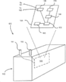
도 2a는 다양한 실시예에 따라, 각각의 모노블록에 배터리 모니터 회로가 배치된 복수의 모노블록을 포함하는 배터리를 도시한다.
도 2b는 다양한 실시예에 따라, 복수의 모노블록을 포함하는 배터리를 도시하며, 여기서 배터리는 연결된 배터리 모니터 회로를 가진다.
도 3은 다양한 실시예에 따라 배터리를 모니터링하는 방법을 도시한다.
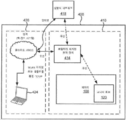
도 4a는 다양한 실시예에 따라, 배터리 모니터링 시스템을 도시한다.
도 4b는 다양한 실시예에 따라 배터리 모니터링 시스템을 도시한다.
도 4c는 다양한 실시예에 따라, 열이 전압 측정치의 범위를 나타내고 행이 온도 측정치의 범위를 나타내는 배터리 동작 히스토리 행렬을 도시한다.
도 4d는 다양한 실시예에 따라, 배터리 모니터 회로가 배치되거나 연결된 배터리를 도시하며, 여기서, 배터리는 부하 및/또는 파워 서플라이에 연결되고, 다양한 로컬 및/또는 원격 전자 시스템과 통신한다.1A illustrates a monoblock in which a battery monitor circuit is disposed, in accordance with various embodiments.
1B illustrates a monoblock to which a battery monitor circuit is connected according to various embodiments.
2A illustrates a battery including a plurality of monoblocks in which battery monitor circuits are disposed in each monoblock, in accordance with various embodiments.
2B illustrates a battery including a plurality of monoblocks, in accordance with various embodiments, wherein the battery has a battery monitor circuit coupled thereto.
3 illustrates a method of monitoring a battery according to various embodiments.
4A illustrates a battery monitoring system, in accordance with various embodiments.
4B illustrates a battery monitoring system in accordance with various embodiments.
4C illustrates a battery operating history matrix in which a column represents a range of voltage measurements and a row represents a range of temperature measurements, in accordance with various embodiments.
4D illustrates a battery in which a battery monitor circuit is disposed or connected in accordance with various embodiments, where the battery is connected to a load and / or power supply and communicates with various local and / or remote electronic systems.
상세한 설명에서 실시예들이 최상의 모드를 포함해, 예시로서 나타난다. 이들 실시예가 해당 분야의 통상의 기술자가 본 발명의 원리를 실시하기 위해 충분히 상세히 기재되었지만, 그 밖의 다른 실시예가 구현될 수 있으며, 논리적, 기계적, 화학적 및/또는 전기적 변화가 본 발명의 원리의 사상 및 범위 내에서 이뤄질 수 있음이 이해될 것이다. 따라서 상세한 설명은 본 명세서에서 한정이 아닌 설명 목적으로 제공된다. 예를 들어, 임의의 방법 기재에서 언급되는 단계들이 임의의 적합한 순서로 실행될 수 있으며 제시된 순서에 한정될 필요는 없다.In the detailed description, embodiments are shown by way of example, including the best mode. While these embodiments have been described in sufficient detail to enable those skilled in the art to practice the principles of the invention, other embodiments may be implemented and logical, mechanical, chemical and / or electrical changes may be made to the spirit of the invention. And within the scope of the invention. Accordingly, the detailed description is provided herein for illustrative purposes, not limitation. For example, the steps mentioned in any method description may be executed in any suitable order and need not be limited to the order presented.
덧붙여, 단순성을 위해, 개별 구성요소의 특정 하위-구성요소 및 시스템의 그 밖의 다른 양태는 본 명세서에서 상세히 기재되지 않을 수 있다. 많은 대안 또는 추가 기능적 관계 또는 물리적 결합이 실제 시스템, 가령, 배터리 모니터링 시스템에서 제공될 수 있음을 알아야 한다. 이러한 기능적 블록은 특정 기능을 수행하도록 구성된 임의의 개수의 적합한 구성요소에 의해 실현될 수 있다.In addition, for simplicity, certain sub-components of individual components and other aspects of the system may not be described in detail herein. It should be appreciated that many alternative or additional functional relationships or physical combinations may be provided in real systems, such as battery monitoring systems. Such functional blocks may be realized by any number of suitable components configured to perform a particular function.
본 발명의 원리는, 예를 들어, 배터리를 조기에 방전시킬 수 있는 모니터링 구성요소, 가령, 전류 센서를 제거함으로써, 배터리의 동작을 개선한다. 또한, 배터리 모니터링 회로가 제조 시점에서 배터리에 내장될 수 있어서, 배터리 수명의 첫째 날부터 재활용되거나 그 밖의 다른 방식으로 폐기될 때까지 배터리를 모니터링하고 연관된 데이터를 저장/전송할 수 있다. 덧붙여, 본 발명의 원리는 다양한 컴퓨팅 장치, 가령, 모바일 통신 장치 및/또는 배터리 모니터 회로의 동작을, 다양한 방식으로 개선하는데, 예를 들면, 신규한 행렬형 데이터베이스에 배터리 히스토리 정보를 컴팩트하게 저장함으로써 배터리 모니터 회로에 의해 사용되는 메모리를 축소함으로써, 제조 비용을 줄이고, 전류 인출을 동작시키며, 배터리 모니터 회로의 동작 수명을 연장하고; 단일 모바일 통신 장치를 통한 복수의 모노블록의 모니터링 및/또는 제어를 촉진시킴으로써, 효율과 처리율을 개선하고; 하나 이상의 배터리와 원격 장치를 연결하는 네트워크를 통해 전송되는 데이터의 양을 감소시킴으로써, 다른 전송되는 데이터를 운반하거나 및/또는 관련 데이터를 더 빠르게 운반하도록 네트워크를 자유롭게 만들며, 또한 통신 비용을 상당히 감소시킨다. The principles of the present invention improve the operation of the battery, for example, by eliminating monitoring components, such as current sensors, that can discharge the battery early. In addition, battery monitoring circuitry can be embedded in the battery at the time of manufacture, allowing the battery to be monitored and associated data stored / transmitted from the first day of battery life until recycled or otherwise discarded. In addition, the principles of the present invention improve the operation of various computing devices, such as mobile communication devices and / or battery monitor circuits, in various ways, for example by compactly storing battery history information in a novel matrix database. By reducing the memory used by the battery monitor circuit, it reduces manufacturing costs, operates current draw, and extends the operating life of the battery monitor circuit; Improving efficiency and throughput by facilitating monitoring and / or control of a plurality of monoblocks through a single mobile communication device; By reducing the amount of data transmitted over the network connecting one or more batteries and remote devices, the network is freed to carry other transmitted data and / or related data faster, and also significantly reduces communication costs. .
또한, 본 발명의 원리는 배터리에 연결된 및/또는 배터리와 연관된 장치, 가령, 셀룰러 라디오 기지국, 전기 지게차, e-바이크 등의 동작을 개선한다. In addition, the principles of the present invention improve the operation of devices connected to and / or associated with batteries, such as cellular radio base stations, electric forklifts, e-bikes, and the like.
또한, 본 발명의 원리의 적용은 실세계에서의 대상을 변형하고 변경한다. 예를 들어, 예시적 알고리즘의 일부로서, 납-산 모노블록의 납 설페이트가 충전 전류의 인가를 통해 납, 납 옥사이드, 및 황산으로 변환되어, 부분적으로 고갈된 납-산 배터리를 완전 충전된 배터리로 변환한다. 덧붙여, 또 다른 예시적 알고리즘의 일부로서, 창고 내 다양한 모노블록이 물리적으로 재배치, 재충전, 또는 심지어 창고에서 제거되거나 대체되어, 창고 내 모노블록의 새로운 전체 구성을 생성할 수 있다.In addition, the application of the principles of the present invention transforms and alters objects in the real world. For example, as part of an exemplary algorithm, lead sulfate of a lead-acid monoblock is converted to lead, lead oxide, and sulfuric acid through the application of a charging current to replace a partially depleted lead-acid battery with a fully charged battery. Convert to In addition, as part of another exemplary algorithm, various monoblocks in a warehouse may be physically relocated, refilled, or even removed or replaced from the warehouse, creating a new overall configuration of monoblocks in the warehouse.
에너지 저장 장치를 모니터링, 유지관리, 및/또는 사용하기 위한 그 밖의 다른 접근법이 존재함이 이해될 것이다. 따라서 본 명세서에서 청구되는 시스템 및 방법이 이러한 임의의 분야 또는 기법을 대신하는 것이 아니며, 기술적 개선, 시간 및 비용 절약, 환경적 이점, 개선된 배터리 수명 등을 제공하는 다양한 특정 진보를 나타낸다. 덧붙여, 본 명세서에 개시된 다양한 시스템 및 방법이 이러한 바람직한 이점을 제공하며, 동시에, 종래의 모니터링 시스템의 비싼 일반적인 전력-소모 구성요소, 즉, 전류 센서를 제거한다. 달리 말하자면, 다양한 예시적 시스템 및 방법이 거의 모든 종래 기술과 극명하게 대조적으로, 전류 센서 및/또는 전류 센서로부터의 정보를 이용하지 않고 이들 없이 구성된다.It will be appreciated that other approaches exist for monitoring, maintaining, and / or using energy storage devices. Thus, the systems and methods claimed herein do not replace any such fields or techniques, and represent various specific advances that provide technical improvements, time and cost savings, environmental benefits, improved battery life, and the like. In addition, the various systems and methods disclosed herein provide this desirable advantage while at the same time eliminating the expensive general power-consuming components of conventional monitoring systems, namely current sensors. In other words, various exemplary systems and methods are constructed without and without the use of information from current sensors and / or current sensors, in sharp contrast to almost all prior art.
하나의 실시예에서, 배터리 모니터 회로가 개시된다. 배터리 모니터 회로는 배터리로부터 및/또는 배터리에 대한 특정 정보, 가령, 날짜/시간, 배터리로부터의 전압 및 온도 정보를 감지, 기록, 및/또는 유선 또는 무선 통신하도록 구성될 수 있다. In one embodiment, a battery monitor circuit is disclosed. The battery monitor circuit may be configured to sense, record, and / or wire or wirelessly communicate specific information from and / or about the battery, such as date / time, voltage and temperature information from the battery.
하나의 실시예에서, 모노블록은 적어도 하나의 전기화학적 전지, 일반적으로, 복수의 전기화학적 전지를 포함하는 에너지 저장 장치이다. 본 명세서에서 사용될 때, 용어 "배터리"는 단일 모노블록을 의미하거나, 전기적으로 직렬 및/또는 병렬로 연결된 복수의 모노블록을 의미할 수 있다. 전기적으로 직렬 및/또는 병렬로 연결된 복수의 모노블록을 포함하는 "배터리"가 종종 또 다른 문헌에서는 "배터리 팩(battery pack)"이라고 지칭된다. 배터리는 양극 단자와 음극 단자를 포함할 수 있다. 덧붙여, 다양한 실시예에서, 배터리는 복수의 양극 및 음극 단자를 포함할 수 있다. 하나의 실시예에서, 배터리 모니터 회로는 배터리 내에 배치되며, 예를 들어, 배터리 하우징 내부에 위치 또는 내장되고 유선 연결을 통해 배터리 단자로 연결된다. 또 다른 실시예에서, 배터리 모니터 회로는 배터리에 연결, 가령, 배터리 하우징의 외부 측에 연결되고 유선 연결을 통해 배터리 단자에 연결된다.In one embodiment, the monoblock is an energy storage device comprising at least one electrochemical cell, generally a plurality of electrochemical cells. As used herein, the term “battery” may mean a single monoblock or may mean a plurality of monoblocks electrically connected in series and / or in parallel. A "battery" comprising a plurality of monoblocks electrically connected in series and / or in parallel is often referred to as a "battery pack" in another document. The battery may include a positive terminal and a negative terminal. In addition, in various embodiments, the battery may include a plurality of positive and negative terminals. In one embodiment, the battery monitor circuit is disposed within the battery, for example located or embedded within the battery housing and connected to the battery terminals via a wired connection. In another embodiment, the battery monitor circuit is connected to the battery, for example to the outside of the battery housing and to the battery terminal via a wired connection.
하나의 실시예에서, 배터리 모니터 회로는 다양한 전기적 구성요소, 가령, 전압 센서, 온도 센서, 명령을 실행하기 위한 프로세서, 데이터 및/또는 명령을 저장하기 위한 메모리, 안테나, 및 송신기/수신기/트랜시버를 포함한다. 일부 실시예에서, 배터리 모니터 회로는 클록, 예를 들어 실시간 클록을 더 포함할 수 있다. 덧붙여, 배터리 모니터 회로는 위치측정 구성요소, 가령, GPS(global positioning system) 수신기 회로를 더 포함할 수 있다. In one embodiment, the battery monitor circuitry includes various electrical components, such as a voltage sensor, a temperature sensor, a processor for executing instructions, a memory for storing data and / or instructions, an antenna, and a transmitter / receiver / transceiver. Include. In some embodiments, the battery monitor circuit may further comprise a clock, for example a real time clock. In addition, the battery monitor circuit may further include a positioning component, such as a global positioning system (GPS) receiver circuit.
특정 실시예에서, 배터리 모니터 회로는 배터리로의 유선 전기 연결에 의해, 배터리의 양극 단자와 음극 단자 간 전압을 모니터링하기 위해 설정되는 전압 센서를 포함할 수 있다. 덧붙여, 배터리 모니터 회로는 배터리의 온도(및/또는 배터리와 연관된 온도)를 모니터링하기 위한 온도 센서를 포함할 수 있다. 배터리 모니터 회로는 전압 센서로부터 모니터링된 전압을 수신하고, 온도 센서로부터 모니터링된 온도 신호를 수신하며, 모니터링된 전압 신호 및 모니터링된 온도 신호를 처리하고, 모니터링된 전압 신호 및 모니터링된 온도 신호를 기초로 전압 데이터 및 온도 데이터를 생성하며, 그 밖의 다른 기능 및 명령을 실행하기 위한 프로세서를 포함할 수 있다. In a particular embodiment, the battery monitor circuit may include a voltage sensor that is set to monitor the voltage between the positive and negative terminals of the battery, by wired electrical connection to the battery. In addition, the battery monitor circuit can include a temperature sensor for monitoring the temperature of the battery (and / or the temperature associated with the battery). The battery monitor circuit receives the monitored voltage from the voltage sensor, receives the monitored temperature signal from the temperature sensor, processes the monitored voltage signal and the monitored temperature signal, and based on the monitored voltage signal and the monitored temperature signal It may include a processor for generating voltage data and temperature data and for executing other functions and instructions.
다양한 실시예에서, 배터리 모니터 회로는 데이터, 가령, 배터리로부터의(및/또는 배터리와 연관된) 전압 데이터 및 온도 데이터를 저장하기 위한 메모리를 포함한다. 덧붙여, 메모리는 프로세서에 의해 실행되기 위한 명령, 외부 장치로부터 수신된 데이터 및/또는 명령 등을 더 포함할 수 있다. 실시예에서, 전압 데이터는 배터리의 단자들 간 전압을 나타내며, 온도 데이터는 배터리 상의 및/또는 배터리 내의 특정 위치에서 측정된 온도를 나타낸다. 또한, 배터리 모니터 회로는 예를 들어, 데이터, 가령, 전압 데이터 및 온도 데이터를 원격 장치로 무선 통신하고, 데이터 및/또는 명령을 수신하기 위한 안테나 및 트랜시버를 포함할 수 있다. 또는, 배터리 모니터 회로는, 예를 들어, 유선 연결을 통해 전압 데이터 및 온도 데이터를 원격 장치로 통신하기 및/또는 데이터 및/또는 명령을 수신하기 위한 배터리 및/또는 원격 장치로의 유선 연결을 포함할 수 있다. 하나의 실시예에서, 배터리 모니터 회로는 전압 데이터 및 온도 데이터를 안테나를 통해 원격 장치로 무선으로 전송한다. 하나의 실시예에서, 배터리 모니터 회로는 전압 데이터 및 온도 데이터를 유선 연결을 통해 원격 장치로 전송한다. 하나의 실시예에서, 배터리 모니터 회로는 배터리 외부에 위치하도록 구성되고 배터리에 전기적으로 유선연결된다.In various embodiments, the battery monitor circuitry includes memory for storing data, such as voltage data and / or temperature data from (and / or associated with) the battery. In addition, the memory may further include instructions for execution by the processor, data and / or instructions received from an external device, and the like. In an embodiment, the voltage data represents the voltage between the terminals of the battery and the temperature data represents the temperature measured at a specific location on and / or within the battery. In addition, the battery monitor circuit may include an antenna and a transceiver for wirelessly communicating data, such as voltage data and temperature data, for example, to receive data and / or commands. Alternatively, the battery monitor circuitry includes, for example, a wired connection to a battery and / or a remote device for communicating voltage data and temperature data to a remote device and / or for receiving data and / or commands via a wired connection. can do. In one embodiment, the battery monitor circuit wirelessly transmits voltage data and temperature data to the remote device via an antenna. In one embodiment, the battery monitor circuit sends voltage data and temperature data to the remote device via a wired connection. In one embodiment, the battery monitor circuit is configured to be external to the battery and is electrically wired to the battery.
하나의 실시예에서, 배터리 모니터 회로는 회로 기판으로의 다양한 구성요소의 연결을 통해 형성될 수 있다. 하나의 실시예에서, 배터리 모니터 회로가 실시간 클록을 더 포함한다. 실시간 클록은, 예를 들어, 배터리에 대한 전압 및 온도 데이터의 수집의 정밀한 타이밍을 위해 사용될 수 있다. 본 명세서에 기재된 바와 같이, 배터리 모니터 회로는 배터리 내부에 위치할 수 있고, 배터리의 내부 온도를 감지하도록 구성되지만, 대안으로 배터리 모니터 회로는 배터리 외부에 위치되고 배터리의 외부 온도를 감지하도록 구성될 수 있다. 또 다른 실시예에서, 배터리 모니터 회로는 모노블록의 내부 온도를 감지하기 위해 모노블록 내에 위치한다. 또 다른 실시예에서, 배터리 모니터 회로는 모노블록의 외부 온도를 감지하기 위해 모노블록에 연결된다. 배터리 모니터 회로로부터의 유선 및/또는 무선 신호가 본 명세서에서 더 기재될 바와 같이 다양한 유용한 동작 및 결정의 기초가 될 수 있다.In one embodiment, the battery monitor circuit can be formed through the connection of various components to the circuit board. In one embodiment, the battery monitor circuit further comprises a real time clock. The real time clock can be used, for example, for precise timing of the collection of voltage and temperature data for the battery. As described herein, the battery monitor circuit may be located inside the battery and configured to sense the internal temperature of the battery, but in the alternative, the battery monitor circuit may be located outside the battery and configured to sense the external temperature of the battery. have. In yet another embodiment, the battery monitor circuit is located within the monoblock to sense the internal temperature of the monoblock. In another embodiment, the battery monitor circuit is connected to the monoblock to sense the external temperature of the monoblock. Wired and / or wireless signals from battery monitor circuitry may be the basis for various useful operations and decisions as will be further described herein.
도 1a 및 1b를 참조해서, 하나의 실시예에서, 배터리(100)가 모노블록을 포함할 수 있다. 하나의 실시예에서, 모노블록은, 에너지 저장 장치로 정의될 수 있다. 모노블록은 적어도 하나의 전기화학적 전지(도시되지 않음)를 포함한다. 다양한 실시예에서, 모노블록은 복수의 전기화학적 전지를 포함하여, 예를 들어, 원하는 전압 및/또는 전류 용량으로 모노블록을 구성할 수 있다. 다양한 실시예에서, 전기화학적 전지는 납-산 유형 전기화학적 전지이다. 임의의 적합한 납-산 전기화학적 전지가 사용될 수 있지만, 하나의 실시예에서 전기화학적 전지는 흡수성 유리 섬유(AGM: absorbent glass mat) 유형 설계를 가진다. 또 다른 실시예에서, 납-산 전기화학적 전지는 겔 유형의 설계를 가진다. 또 다른 실시예에서, 납-산 전기화학적 전지는 플러디드(flooded)(벤티드(vented))형 설계를 가진다. 그러나 본 발명의 다양한 원리가 다양한 배터리 화학, 비제한적 예를 들면, 니켈-카드뮴(NiCd), 니켈 금속 히드라이드(NiMH), 리튬 이온, 리튬 코발트 옥사이드, 리튬 철 포스페이트, 리튬 이온 망간 옥사이드, 리튬 니켈 망간 코발트 옥사이드, 리튬 니켈 코발트 알루미늄 옥사이드, 리튬 티타네이트, 리튬 황, 재충전 알칼라인 등에 적용 가능하며, 따라서 본 명세서에서의 납-산 배터리에 대한 개시는 한정이 아니라 설명을 위해 제공된다.1A and 1B, in one embodiment, the
배터리(100)는 하우징(110)을 가질 수 있다. 예를 들어, 배터리(100)는 내구성 있는 물질로 만들어진 밀봉된 모노블록 납-산 에너지 저장 케이스를 포함하도록 구성될 수 있다. 배터리(100)는 양극 단자(101) 및 음극 단자(102)를 더 포함할 수 있다. 밀봉된 케이스는 양극 단자(101) 및 음극 단자(102)가 통과하는 개구부를 가질 수 있다.The
도 2a 및 2b를 참조해서, 배터리(200)가 복수의 전기적으로 연결된 모노블록, 가령, 배터리(100)를 포함할 수 있다. 배터리(200) 내 모노블록은 전기적으로 병렬 및/또는 직렬로 연결될 수 있다. 하나의 실시예에서, 배터리(200)는 적어도 하나의 모노블록 스트링을 포함할 수 있다. 하나의 실시예에서, 제1 스트링은 전기적으로 직렬 연결된 복수의 모노블록을 포함할 수 있다. 또 다른 실시예에서, 제2 스트링은 전기적으로 직렬 연결되는 복수의 모노블록을 포함할 수 있다. 배터리 내에 둘 이상의 모노블록 스트링이 존재하는 경우, 제1, 제2, 및/또는 추가 스트링이 전기적으로 병렬 연결될 수 있다. 모노블록의 직렬/병렬 연결이 최종적으로 배터리(200)의 양극 단자(201) 및 음극 단자(202)에 연결되어, 예를 들어, 배터리(200)에 대한 원하는 전압 및/또는 전류 특성 또는 용량을 달성할 수 있다. 따라서 하나의 실시예에서, 배터리(200)는 둘 이상의 모노블록을 포함한다. 배터리(200)는 본 명세서에서 전력 도메인(power domain)으로 지칭될 수 있다.2A and 2B,
배터리(200)는 캐비넷 또는 하우징(210)을 가질 수 있다. 예를 들어, 배터리(200)는 배터리를 보호하고 배터리의 동작을 위해 적절한 환경을 제공하기 위한 열적 및 기계적 구조를 포함할 수 있다. The
도 1a, 1b, 2a 및 2b를 참조하면, 예시적 적용예에서, 배터리(100/200)는 전력을 백-업(back-up)하는 데 사용될 수 있다(무정전 전력 공급원(UPS: uninterrupted power supply)라고도 지칭됨). 또한, 배터리(100/200)는 셀룰러 라디오 기지국 적용예에서 사용될 수 있고 전력 그리드(power grid)에 연결될 수 있다(가령, 정류기/인버터를 통해 교류에, DC 마이크로그리드 등에 연결될 수 있다). 또 다른 실시예에서, 배터리(100/200)는 AC 전력 그리드에 연결되고 최고수요 절감(peak shaving), 수요 관리, 전력 조절, 주파수 응답 및/또는 반응성 전력 공급기 같은 적용예에서 사용된다. 또 다른 실시예에서, 배터리(100/200)는 다양한 차량(가령, 자전거), 산업 장비(가령, 지게차), 및 도로 조명, 중형 및 대형 차량에게 원동력을 제공하는 구동 시스템에 연결된다. 또 다른 적용예에서, 배터리(100/200)는 단기 또는 장기간 에너지 저장이 바람직한 임의의 적합한 적용예에서 사용될 수 있다. 배터리 (100/200)는 단일 물품으로서 상거래로 배송되거나, 다른 모노블록과 함께(예를 들어, 많은 다른 모노블록과 함께 팰릿(pallet)으로) 상거래로 배송되거나, 또는 배터리의 일부로서 다른 모노블록과 함께 상거래로 배송 될 수 있다(예를 들어, 배터리(200)를 형성하는 복수의 배터리(100)). 1A, 1B, 2A, and 2B, in an exemplary application, the
하나의 실시예에서, 배터리 모니터 회로(120)는 배터리(100) 내에 연결되어 배치될 수 있고, 대안으로, 배터리 모니터 회로(120)는 배터리(100/200) 외부에 연결될 수 있다. 하나의 실시예에서, 도 1a에 도시된 바와 같이, 단일 배터리 모니터 회로(120)는 단일 모노블록(배터리(100) 참조) 내에 배치되고 이와 연관될 수 있다. 또 다른 실시예에서, 도 1b에 도시된 바와 같이, 단일 배터리 모니터 회로(120)는 단일 모노블록(배터리(100) 참조)에 연결되고 이와 연관될 수 있다. 하나의 실시예에서, 각각 그 내부에 배터리 모니터 회로(120)를 갖는 복수의 배터리(100)는, 도 2a에 도시된 바와 같이, 단일 배터리(200) 내부에 배치되고 이의 일부를 포함할 수 있다. 또 다른 실시예에서, 도 2b에 도시된 바와 같이, 단일 배터리 모니터 회로(120)는 외부에서 단일 배터리(200)에 연결되고 이와 연관될 수 있다. 또 다른 실시예에서, 둘 이상의 배터리 모니터 회로(120)는 단일 배터리의 하나 이상의 부분 내에 배치되고 이에 연결된다. 예를 들어, 제1 배터리 모니터 회로는 배터리의 제1 모노블록 내에 배치되고 이와 연결될 수 있으며, 제2 배터리 모니터 회로는 배터리의 제2 모노블록 내에 배치되고 이와 연결될 수 있다. 유사한 방식이 배터리 외부에 연결된 복수의 배터리 모니터 회로(120)를 연관시키는 데 사용될 수 있다. In one embodiment, the
배터리 모니터 회로(120)는 전압 센서(130), 온도 센서(140), 프로세서(150), 트랜시버(160), 안테나(170), 및 저장 매체 또는 메모리(도면에 도시되지 않음)를 포함할 수 있다. 하나의 실시예에서, 배터리 모니터 회로(120)는 모노블록 또는 배터리(100/200)와 연관된 전압 및 온도를 감지하고, 감지된 전압 및 온도를 이들 판독값의 연관된 시점과 함께 메모리에 저장되며, 배터리 모니터 회로(120)로부터 하나 이상의 외부 위치로 전압 및 온도 데이터를 (이의 연관된 시점과 함께) 전송하도록 구성된다. The
하나의 실시예에서, 전압 센서(130)는 유선으로 배터리(100/200)의 양극 단자(101/201)에 그리고 유선으로 배터리(100/200)의 음극 단자(102/202)로 전기적으로 연결될 수 있다. 하나의 실시예에서, 전압 센서(130)는 배터리(100/200)의 전압을 감지하도록 구성된다. 예를 들어, 전압 센서(130)는 양극 단자(101/201)와 음극 단자(102/202) 간 전압을 감지하도록 구성될 수 있다. 하나의 실시예에서, 전압 센서(130)는 아날로그-디지털 변환기를 포함한다. 그러나 배터리(100/200)의 전압을 감지하기 위한 임의의 적합한 장치가 사용될 수 있다.In one embodiment, the
하나의 실시예에서, 온도 센서(140)는 배터리(100/200)의 온도 측정치를 감지하도록 구성된다. 하나의 실시예에서, 온도 센서(140)는 배터리(100/200) 내부 위치에서 온도 측정치를 감지하도록 구성될 수 있다. 온도 측정치가 배터리(100/200)를 포함하는 전기화학적 셀의 온도를 반영하도록 온도 측정치가 취해지는 위치가 선택될 수 있다. 또 다른 실시예에서, 온도 센서(140)는 배터리(100/200) 외부 위치에서 온도 측정치를 감지하도록 구성될 수 있다. 온도 측정이 수행되는 위치는 온도 측정이 주로 배터리(100/200)를 포함하는 전기화학적 전지의 온도 자체를 반영하고 이웃하는 배터리 또는 주위 온도에 의해서는 간접적으로, 이차적으로 또는 덜 유의미하게만 영향받도록 선택 될 수 있다. 다양한 실시예에서, 배터리 모니터 회로(120)는 배터리(100/200)의 내부에 위치하도록 구성된다. 덧붙여, 다양한 실시예에서, 배터리(100/200) 내부의 배터리 모니터 회로(120)의 존재가 배터리(100/200)의 외부에서의 시각적 검사를 통해서는 보이거나 검출되지 않을 수 있다. 또 다른 실시예에서, 배터리 모니터 회로(120)가 배터리(100/200) 외부에 위치, 가령, 배터리(100/200)에 부착, 와이어에 의해 배터리(100/200)에 연결, 및/또는 배터리(100/200)와 함께 이동하도록 위치하도록 구성되어, 배터리(100/200)의 양극 단자 및 음극 단자로 전기적으로 연결된 채 유지될 수 있다. In one embodiment,
하나의 실시예에서, 온도 센서(140)는 배터리(100/200) 외부 위치에서 온도 측정치를 감지하도록 구성될 수 있다. 온도 측정이 수행되는 위치는 온도 측정이 주로 배터리(100/200)의 온도 자체를 반영하고 이웃하는 모노블록 또는 주위 온도에 의해서는 간접적으로, 이차적으로 또는 덜 유의미하게만 영향받도록 선택 될 수 있다. 하나의 실시예에서, 온도 센서 (140)는 열전대, 서미스터, 온도 감지 집적 회로 등을 포함한다. 특정 실시예에서, 온도 센서(140)는 배터리(100/200)의 양극 단자 또는 음극 단자에 배터리 모니터 회로(120)를 연결할 때 내장된다.In one embodiment,
하나의 실시예에서, 배터리 모니터 회로(120)는 전압 센서, 온도 센서, 프로세서, 저장 매체, 트랜시버, 안테나 및/또는 그 밖의 다른 적합한 구성요소를 지지하고 전기적으로 연결하기 위한 인쇄 회로 기판을 포함한다. 또 다른 실시예에서, 배터리 모니터 회로(120)는 하우징(도시되지 않음)을 포함한다. 상기 하우징은 배터리 모니터 회로(120) 내 전자소자를 보호하기 위한 임의의 적합한 물질, 가령, 내구성 있는 플라스틱으로 구성될 수 있다. 하우징은 임의의 적합한 형태 또는 폼 팩터로 만들어질 수 있다. 하나의 실시예에서, 배터리 모니터 회로(120)의 하우징이 배터리(100/200)에 외부에서 부착 또는 그 내부에 배치되도록 구성되며, 예를 들어, 접착제, 포팅 물질(potting material), 볼트, 나사, 클램프 등을 통해 고정될 수 있다. 덧붙여, 임의의 적합한 부착 장치 또는 방법이 배터리(100/200) 상에, 근방에, 및/또는 그 내부에, 배터리 모니터 회로(120)를 원하는 위치 및/또는 배향으로 유지하도록 사용될 수 있다. 이러한 방식으로, 배터리(100/200)는 이송, 설치, 이용 등이 될 수 있기 때문에, 배터리 모니터 회로(120)는 여기에 고정적으로 배치 및/또는 여기에 연결된 채 유지되며, 따라서 함께 연결되어 동작 가능하다. 예를 들어, 배터리 모니터 회로(120)는 배터리(100/200)에 직접 부착되지 않을 수 있으며 배터리와 함께 이동되도록 배터리에 인접하게 위치할 수 있다. 예를 들어, 배터리 모니터 회로(120)는 배터리(100/200)를 포함하는 산업 지게차의 프레임 또는 본체에 연결될 수 있다.In one embodiment, the
하나의 실시예에서, 배터리 모니터 회로(120)는 공중망, 가령, 인터넷을 통해 액세스 가능한 시각 신호 같은 외부 시각 표준으로의 어떠한 연결(유선 또는 무선 연결)과도 무관하게, 표준 시각, 가령, UTC(Universal Time Coordinated)을 기준으로 시각을 유지할 수 있는 실시간 클록을 더 포함한다. 클록은 현재 시각/날짜(또는 상대 시각)을 프로세서(150)로 제공하도록 구성된다. 하나의 실시예에서, 프로세서(150)는 전압 및 온도 측정치를 수신하고, 데이터가 감지/저장된 시점과 연관된 전압 및 온도 데이터를 저장 매체에 저장하도록 구성된다. 하나의 실시예에서, 전압, 온도 및 시간 데이터가 저장 매체에 데이터베이스, 플랫 파일, 2진수의 블롭(blob), 또는 그 밖의 다른 임의의 적합한 포맷 또는 구조의 형태로 저장될 수 있다. 또한, 프로세서(150)는 추가 데이터를 로그의 형태로 저장 매체에 저장하도록 구성될 수 있다. 예를 들어, 프로세서는 전압 및/또는 온도가 설정 가능한 양만큼 변할 때마다 로그할 수 있다. 하나의 실시예에서, 프로세서(150)는 마지막 측정된 데이터를 최신 측정 데이터에 비교하고, 최신 측정 데이터가 마지막 측정 데이터로부터 적어도 이 설정 가능한 양만큼 변하는 경우에만 최신 측정 데이터를 로그한다. 비교는 임의의 적합한 간격, 예를 들어 매초 마다, 5초마다, 10초마다, 30초마다, 매분 마다, 10분 마다 등으로 이루어질 수 있다. 저장 매체는 배터리 모니터 회로(120) 상에 위치하거나 원격지에 위치할 수 있다. 프로세서(150)는 추가 분석, 보고 및/또는 동작을 위해 로그된 온도/전압 데이터를 원격 장치로 (무선으로 또는 유선 연결에 의해) 전송하도록 더 구성될 수 있다. 하나의 실시예에서, 원격 장치는 전송된 데이터 로그를 이전에 전송된 로그와 함께 연결(stitch)하여, 시간상 연속인 로그를 형성하도록 구성될 수 있다. 이러한 방식으로, 배터리 모니터 회로(120)에 대한 로그의 크기(및 이를 저장하는 데 필요한 메모리)가 최소화될 수 있다. 프로세서(150)는 원격 장치로부터 명령을 수신하도록 더 구성될 수 있다. 프로세서(150)는 신호의 형태로 데이터를 트랜시버(160)로 제공함으로써 배터리 모니터 회로(120)로부터의 시간, 온도 및 전압 데이터를 전송하도록 더 구성될 수 있다.In one embodiment, the
또 다른 실시예에서, 배터리 모니터 회로(120)는 실시간 클록 없이 구성된다. 대신, 데이터가 프로세서(150)에 의해 제어되는 일정한 시간격으로 샘플링된다. 각각의 간격은 시퀀스 번호로 순차적으로 넘버링되어, 이를 고유하게 식별할 수 있다. 샘플링된 데이터는 모두 로그될 수 있고, 대안으로, 설정 가능한 양보다 많이 변한 데이터만 로그될 수 있다. 주기적으로, 배터리 모니터 회로(120)가 시간 표준, 가령, 인터넷을 통해 액세스 가능한 네트워크 시간 신호에 연결될 때, 프로세서 시간은 시간 표준에 의해 나타나는 실시간과 동기화된다. 그러나, 두 경우 모두, 데이터가 샘플링된 간격 시퀀스 번호도 역시 데이터와 함께 로그된다. 그런 다음 이는 배터리 모니터 회로(120) 상의 실시간 클록을 필요로 하지 않고, 데이터 샘플들 간 시간 간격을 수정한다. 원격 장치로의 데이터 로그의 전송 후, 간격이 원격 장치(본 명세서에서 더 기재됨)와 동기화되며, 이는 예를 들어, 인터넷 연결을 통해 동기화되는 실시간(가령, UTC)을 유지한다. 따라서 원격 장치가 배터리 모니터 회로(120) 및 프로세서(150)와의 동기화를 통해 시간을 제공하도록 구성된다. 배터리 모니터 회로(120) 또는 원격 장치에 저장된 데이터가 모노블록이 특정 온도 및/또는 전압인 때의 누적 시간량을 포함할 수 있다. 프로세서(150)는 신호의 형태로 데이터를 트랜시버(160)로 제공함으로써 배터리 모니터 회로(120)로부터의 누적 시간, 온도 및 전압 데이터를 전송하도록 더 구성될 수 있다.In yet another embodiment, the
하나의 실시예에서, 배터리에 대한 시간, 온도 및 전압 데이터가, 예를 들어, 하나의 축에 전압 범위를 또 다른 축에 온도 범위를 포함하는 파일, 데이터베이스 또는 행렬로 저장될 수 있으며, 여기서, 이 테이블의 셀은 배터리가 특정 전압/온도 상태에서 보내는 시간을 나타내도록 각각의 셀 내 카운터를 증분시키도록 구성된다(즉, 배터리 동작 히스토리 행렬을 형성할 수 있음). 배터리 동작 히스토리 행렬은 배터리 모니터 회로(120)의 메모리 및/또는 원격 장치에 저장될 수 있다. 예를 들어, 도 4c를 참조하면, 예시적 배터리 동작 히스토리 행렬(450)이 열(460)을 포함할 수 있고, 각각의 열이 특정 전압 또는 전압 측정치의 범위를 나타낸다. 예를 들어, 제1 열이 0볼트 내지 1볼트의 전압 범위를 나타낼 수 있으며, 제2 열이 1볼트 내지 9볼트의 전압 범위를 나타낼 수 있고, 제3 열이 9볼트 내지 10볼트의 전압 범위를 나타내는 등일 수 있다. 배터리 동작 히스토리 행렬(450)은 행(470)을 더 포함할 수 있으며, 각각의 행은 특정 온도(+/-) 또는 온도 측정치 범위를 나타낸다. 예를 들어, 제1 행은 10℃ 미만의 온도를 나타낼 수 있고, 제2 행은 10℃ 내지 20℃의 온도 범위를 나타낼 수 있으며, 제3 행은 20℃ 내지 30℃의 온도 범위를 나타낼 수 있는 등이다. 임의의 적합한 스케일 및 수의 행/열이 사용될 수 있다. 하나의 실시예에서, 배터리 동작 히스토리 행렬(450)은 배터리가 각각의 지정된 전압/온도 상태에서 보내는 시간량의 누적 히스토리를 저장한다. 다시 말해, 배터리 동작 히스토리 행렬(450)은 배터리가 특정 전압/온도 범위에 있는 동안의 시간량을 집성(또는 상관)시킨다. 구체적으로, 이러한 시스템은 특히, 데이터를 얼마나 오래 기록하는지에 무관하게, 저장 크기가 증가하지 않기 때문에(또는 미미한 양만 증가) 바람직하다. 배터리 동작 히스토리 행렬(450)이 차지하는 메모리는 종종 전압/온도 데이터를 집성하기 시작한 첫날과 수년 후 또는 배터리 수명의 거의 끝에서 동일한 크기이다. 이 기법은, 이 기법을 이용하지 않는 구현예에 비교해서, 이 데이터를 저장하는 데 필요한 메모리 및 전력의 크기를 감소시킴으로써, 배터리 모니터 회로(120) 컴퓨팅 장치의 동작을 상당히 개선한다. 덧붙여, 배터리 전압/온도 데이터가 주기적으로 원격 장치로 전송될 수 있다. 이는 데이터를 효과적으로 게이팅하고, 비-게이팅 기법과 비교해서, 데이터를 저장하고 데이터를 전송하는 데 필요한 전력을 감소시키고, 메모리의 크기를 감소시키며, 데이터 전송 시간을 감소시킨다.In one embodiment, time, temperature, and voltage data for a battery may be stored, for example, in a file, database, or matrix that includes a voltage range on one axis and a temperature range on another axis. The cells in this table are configured to increment the counters in each cell to represent the time the battery spends in a particular voltage / temperature state (ie, may form a battery operation history matrix). The battery operation history matrix may be stored in a memory and / or remote device of the
하나의 실시예에서, 트랜시버(160)는 임의의 적절한 전송기 및/또는 수신기일 수 있다. 예를 들어, 트랜시버(160)는 신호를 상향-변환(up-convert)하여 안테나(170)를 통해 신호를 전송하거나 및/또는 안테나(170)로부터 신호를 수신하고, 신호를 하향-변환(down-convert)하고 이를 프로세서(150)로 제공하도록 구성될 수 있다. 하나의 실시예에서, 트랜시버(160) 및/또는 안테나(170)는 배터리 모니터 회로(120)와 원격 장치 간에 신호를 무선으로 전송하고 수신하도록 구성될 수 있다. 임의의 적합한 통신 표준, 가령, 무선 주파수 통신, Wi-Fi, Bluetooth®, Bluetooth Low Energy (BLE), Bluetooth Low Power (IPv6/6LoWPAN), 셀룰러 무선 통신 표준(2G, 3G, 4G, LTE, 5G 등) 등을 이용해 무선 전송이 이뤄질 수 있다. 하나의 실시예에서, 저 전력의 단거리 신호를 이용해 무선 전송이 이뤄짐으로써, 배터리 모니터 회로에 의해 인출되는 전력을 낮게 유지할 수 있다. 하나의 실시예에서, 프로세서(150)는 전력 소비량을 최소화 또는 감소시키기에 적합한 스케줄로, 웨이크-업(wake-up)하며, 무선 통신하고, 다시 수면 상태로 가도록 구성된다. 이는 배터리 모니터 회로(120)의 모니터링이 배터리를 조기에 방전시키지 않도록 하기 때문에 바람직하다. 배터리 모니터 회로(120) 기능, 가령, 웨이크업/수면 및 데이터 수집 기능이, 배터리(100/200)를 방전시키지 않으면서 온도 및 전압 데이터의 정확한 감지 및 보고를 촉진시킨다. 다양한 실시예에서, 배터리 모니터 회로(120)는 자신이 배치된 및/또는 모니터링을 위해 연결된 배터리에 의해 전력을 공급 받는다. 또 다른 실시예에서, 배터리 모니터 회로(120)는 그리드 또는 또 다른 전력 공급기, 가령, 로컬 배터리, 태양 패널, 연료 전지, 유도성 RF 에너지 수확 회로 등에 의해 전력을 공급 받는다.In one embodiment, the
일부 실시예에서, Bluetooth 프로토콜의 사용이 단일 원격 장치가 복수의 배터리(각각의 배터리가 배터리 모니터 회로(120)를 구비함)와 상관된 복수의 신호를 수신하고 처리하는 것을 촉진하며, 이러한 것을 신호 간섭 없이 수행하는 것을 촉진한다. 원격 장치와 배터리 모니터 회로(120)를 각각 구비한 복수의 배터리 간 이러한 일대다 관계가, 저장 및 배송 채널에서 배터리를 모니터링하는 특별한 이점이다.In some embodiments, the use of the Bluetooth protocol facilitates a single remote device to receive and process a plurality of signals that are correlated with a plurality of batteries, each battery having a
하나의 실시예에서, 배터리 모니터 회로(120)가 배터리 내부에 위치한다. 예를 들어, 배터리 모니터 회로(120)는 배터리(100)의 하우징 내에 배치될 수 있다. 다양한 실시예에서, 배터리 모니터 회로(120)는 모노블록 또는 배터리 내부에 위치한다. 배터리 모니터 회로(120)는 배터리(100) 외부에서 보거나 액세스할 수 없도록 감춰져 있을 수 있다. 이는 사용자에 의한 조작을 막을 수 있으며, 따라서 수행되는 보고의 신뢰성을 개선할 수 있다. 배터리 모니터 회로(120)는 배터리(100)의 리드(lid) 바로 아래에, 또는 인터커넥트 스트랩(납 인터-커낵팅 바)에 근접하여, 또는 그 밖의 다른 곳에 위치할 수 있다. 이러한 방식으로, 전기화학적 전지로 인한 모노블록의 온도 및 인터커넥트 스트랩의 열 출력이 정교하게 측정될 수 있다. In one embodiment, the
하나의 실시예에서, 배터리 모니터 회로(120)는 배터리의 외부에 위치한다. 예를 들어, 배터리 모니터 회로(120)는 배터리(100/200) 외부에 부착될 수 있다. 또 다른 예시에서, 배터리 모니터 회로(120)는 배터리(100/200)에 근접하게 위치하며, 이때 전압 센서(130)가 배터리(100/200)의 양극 단자와 음극 단자에 유선 연결된다. 또 다른 실시예에서, 배터리 모니터 회로(120)는 배터리(100/200)에 연결되어, 배터리(100/200)와 함께 이동될 수 있다. 예를 들어, 배터리 모니터 회로(120)가 차량의 프레임에 연결되고 배터리(100/200)가 차량의 프레임에 연결되는 경우, 둘 모두 함께 이동될 것이며, 전압 및 온도 모니터링 센서(130 및 140)는 차량이 이동할 때 자신의 적정 기능을 계속 수행할 수 있다.In one embodiment, the
하나의 실시예에서, 온도 센서(140)는 모노블록의 단자들 중 하나의 온도를 감지하도록 구성될 수 있다. 하나의 실시예에서, 온도 센서(140)는 배터리 내 두 개의 모노블록 사이의 위치 또는 공간의 온도, 복수의 모노블록을 포함하는 배터리 내 공기 온도, 모노블록의 벽의 대략 중간 위치에서의 온도 등을 측정하도록 구성될 수 있다. 이러한 방식으로, 배터리 모니터 회로(120)에 의해 감지되는 온도가 배터리(100/200) 및/또는 그 내부의 전기화학적 전지의 온도를 더 잘 나타낼 수 있다. 일부 실시예에서, 온도 센서(140)는 배터리 모니터 회로(120)의 인쇄 회로 기판 상에 위치 및/또는 이에 직접 연결될 수 있다. 덧붙여, 온도 센서(140)는 모노블록 또는 배터리와 연관된 온도를 감지하기 위한 모노블록 또는 배터리 내부의 임의의 적합한 위치에 위치할 수 있다. 또는, 온도 센서(140)는 모노블록 또는 배터리와 연관된 온도를 감지하기 위한 모노블록 또는 배터리 외부의 임의의 적합한 위치에 위치할 수 있다.In one embodiment,
따라서 도 3을 참조하면, 적어도 하나의 전기화학적 전지를 포함하는 배터리(100/200)를 모니터링하기 위한 예시적 방법(300)이: 배터리 단자에 유선 연결된 전압 센서(130)로 배터리(100/200)의 전압을 감지하는 단계(302), 및 전압이 감지된 때의 전압 및 시간을 저장 매체에 기록하는 단계(304), 배터리(100/200) 내에 및/또는 배터리 상에 배치된 온도 센서(140)를 이용해 배터리(100/200)와 연관된 온도를 감지하는 단계(306), 및 온도가 감지된 때의 온도 및 시간을 저장 매체에 기록하는 단계(308), 및 저장 매체에 기록된 전압, 온도 및 시간 데이터를 원격 장치로 유선 또는 무선 전송하는 단계(310)를 포함한다. 전압, 온도, 및 시간 데이터는, 그 밖의 다른 관련 데이터와 함께, 평가, 분석, 처리, 및/또는 다양한 컴퓨팅 시스템, 자원 및/또는 애플리케이션으로의 입력으로서 이용될 수 있다(단계(312)). 하나의 예시적 방법에서, 전압 센서(130), 온도 센서(140), 및 저장 매체가 배터리(100) 내부에서 배터리 모니터 회로(120) 상에 위치된다. 또 다른 예시적 방법에서, 전압 센서(130), 온도 센서(140), 및 저장 매체가 배터리(100/200) 외부에서 배터리 모니터 회로(120) 상에 위치된다. 덧붙여, 방법(300)은 전압, 온도 및/또는 시간 데이터에 응답하여 다양한 동작을 취하는 단계(단계(314)), 가령, 배터리를 충전하기, 배터리를 방전시키기, 배터리를 창고로부터 이동시키기, 배터리를 새 배터리로 교체하기 등을 포함할 수 있다. Thus, referring to FIG. 3, an
이제 도 4a 및 4b를 참조하여, 하나의 실시예에서, 배터리 모니터 회로(120)는 원격 장치와 데이터를 통신하도록 구성된다. 원격 장치는 복수의 배터리로부터 데이터를 수신하도록 구성될 수 있으며, 이때 각각의 배터리에 배터리 모니터 회로(120)가 구비된다. 예를 들어, 원격 장치가 개별 배터리(100)로부터 데이터를 수신할 수 있으며, 각각의 배터리는 배터리 모니터 회로(120)에 연결되어 있다. 그리고 또 다른 실시예에서, 원격 장치는 개별 배터리(200)로부터 데이터를 수신할 수 있으며, 이때, 각각의 배터리(200)는 배터리 모니터 회로(120)에 연결되어 있다. Referring now to FIGS. 4A and 4B, in one embodiment, the
예시적 시스템(400)은 각각의 배터리(100/200)와 연관된 데이터를 수집 및 이용하도록 배치된다. 일반적으로, 원격 장치는 물리적으로 배터리(100/200) 또는 배터리 모니터 회로(120)의 일부가 아닌 전자 장치이다. 시스템(400)은 로컬 부분(410) 및/또는 원격 부분(420)을 포함할 수 있다. 로컬 부분(410)은 하나 또는 복수의 배터리(100/200)에 비교적 가까이 위치하는 구성요소를 포함한다. "비교적 가까이"는, 하나의 실시예에서, 배터리 모니터 회로 안테나의 무선 신호 범위 내를 의미한다. 또 다른 실시예에서, "비교적 가까이"는 Bluetooth 범위 내, 동일한 캐비넷 안, 동일한 방 안 등을 의미한다. 로컬 부분(410)은, 예를 들어, 하나 이상의 배터리(100/200), 배터리 모니터 회로(120), 및 선택사항으로서, 로컬 부분(410) 내에 위치하는 로컬 위치 원격 장치(414)를 포함할 수 있다. 덧붙여, 로컬 부분은, 예를 들어, 게이트웨이를 포함할 수 있다. 상기 게이트웨이는 각각의 배터리(100/200)로부터 데이터를 수신하도록 구성될 수 있다. 상기 게이트웨이는 각각의 배터리(100/200)로 명령을 전송하도록 더 구성될 수 있다. 하나의 실시예에서, 게이트웨이는 게이트웨이에서 무선으로 송신/수신하기 위한, 및/또는 로컬하게 위치하는 원격 장치(414)와 통신하기 위한 안테나를 포함한다. 로컬하게 위치하는 원격 장치(414)는, 하나의 실시예에서, 스마트폰, 태블릿, 또는 그 밖의 다른 전자 모바일 장치이다. 또 다른 실시예에서, 로컬하게 위치하는 원격 장치(414)는 컴퓨터, 네트워크, 서버 등이다. 또 다른 실시예에서, 로컬하게 위치하는 원격 장치(414)는 온보드 차량 전자 시스템이다. 또한, 일부 실시예에서, 게이트웨이는 로컬하게 위치하는 원격 장치(414)로서 기능할 수 있다. 게이트웨이와 로컬하게 위치하는 원격 장치(414) 간 예시적 통신이, 임의의 적합한 유선 또는 무선 방식을 통해, 가령, Bluetooth 프로토콜을 통해 이뤄질 수 있다.
일부 실시예에서, 원격 장치는 로컬 부분(410)에 위치하지 않고, 원격 부분(420)에 위치한다. 원격 부분(420)은 임의의 적합한 백-엔드 시스템을 포함할 수 있다. 예를 들어, 원격 부분(420) 내 원격 장치는 컴퓨터(424)(가령, 데스크-톱 컴퓨터, 랩톱 컴퓨터, 서버, 모바일 장치, 또는 본 명세서에 기재된 데이터를 이용 또는 처리하기 위한 임의의 적합한 장치)를 포함할 수 있다. 원격 부분은 클라우드-기반 컴퓨팅 및/또는 저장 서비스, 주문형 컴퓨팅 자원, 또는 임의의 적합한 유사한 구성요소를 더 포함할 수 있다. 따라서, 다양한 실시예에서, 원격 장치는, 컴퓨터(424), 서버, 백-엔드 시스템, 데스크톱, 클라우드 시스템 등일 수 있다. In some embodiments, the remote device is not located in the
하나의 실시예에서, 배터리 모니터 회로(120)는 배터리 모니터 회로(120)와 로컬하게 위치하는 원격 장치(414) 사이에 직접 데이터를 통신하도록 구성될 수 있다. 하나의 실시예에서, 배터리 모니터 회로(120)와 로컬하게 위치하는 원격 장치(414) 간 통신이 무선 전송, 가령, Bluetooth 전송일 수 있다. 또한, 임의의 적합한 무선 프로토콜이 사용될 수 있다. 배터리 모니터 회로(120)가 배터리(100/200) 외부에 있는 일부 실시예에서, 통신은 유선, 예를 들어, 이더넷 케이블, USB 케이블, 트위스티드 페어, 및/또는 그 밖의 다른 임의의 적합한 와이어 및 대응하는 유선 통신 프로토콜에 의해 이뤄질 수 있다.In one embodiment, the
하나의 실시예에서, 배터리 모니터 회로(120)가 셀룰러 네트워크(418) 및 그 밖의 다른 네트워크, 가령, 인터넷을 통해 원격 장치와 통신하기 위한 셀룰러 모뎀을 더 포함한다. 예를 들어, 데이터는 셀룰러 네트워크(418)를 통해 컴퓨터(424) 또는 로컬하게 위치하는 원격 장치(414)와 공유될 수 있다. 따라서 배터리 모니터 회로(120)는 인터넷 연결된 세계면 어디든 배포되도록 셀룰러 네트워크(418) 내지 그 밖의 다른 네트워크,가령, 인터넷을 통해 온도 및 전압 데이터를 원격 장치로 전송하고 원격 장치로부터 통신을 수신하도록 구성될 수 있다. In one embodiment, the
다양한 실시예에서, 로컬 부분(410)으로부터의 데이터가 원격 부분(420)으로 통신된다. 예를 들어, 배터리 모니터 회로(120)로부터의 데이터 및/또는 명령이 원격 부분(420)에서 원격 장치로 통신될 수 있다. 하나의 실시예에서, 로컬하게 위치하는 원격 장치(414)는 원격 부분(420) 내 컴퓨터(424)와 데이터 및/또는 명령을 통신할 수 있다. 하나의 실시예에서, 이들 통신은 인터넷을 통해 전송된다. 통신은 경우에 따라 보안화 및/또는 암호화되어, 통신의 보안을 지킬 수 있다. In various embodiments, data from
하나의 실시예에서, 이들 통신은 임의의 적합한 통신 프로토콜, 가령, TCP/IP, WLAN, 이더넷(Ethernet), WiFi, 셀룰러 라디오 등을 이용해 전송될 수 있다. 하나의 실시예에서, 로컬하게 위치하는 원격 장치(414)가 로컬 네트워크를 통해 인터넷에 연결되고 이로써 원하는 원격 위치의 원격 장치에 연결된다. 하나의 실시예에서, 로컬하게 위치하는 원격 장치(414)가 셀룰러 네트워크, 가령, 셀룰러 네트워크(418)를 통해, 인터넷으로, 그리고 이로 인해 임의의 원하는 원격지에 위치하는 원격 장치로 연결된다.In one embodiment, these communications may be transmitted using any suitable communication protocol, such as TCP / IP, WLAN, Ethernet, WiFi, cellular radio, or the like. In one embodiment, a locally located
하나의 실시예에서, 이 데이터는 서버에서 수신되거나, 컴퓨터(424)에서 수신되거나, 클라우드-기반 저장 시스템, 서버, 데이터베이스 등에 저장된다. 하나의 실시예에서, 이 데이터는 배터리 모니터 회로(120), 로컬하게 위치하는 원격 장치(414), 컴퓨터(424) 및/또는 임의의 적합한 원격 장치에 의해 처리될 수 있다. 따라서 이 배터리 모니터 회로(120)에서 발생하는 것으로 기재된 처리 및 분석이 또한 배터리 모니터 회로(120), 로컬하게 위치하는 원격 장치(414), 컴퓨터(424) 및/또는 그 밖의 다른 임의의 원격 장치에서 완전히 또는 부분적으로 발생할 수 있음이 자명할 것이다.In one embodiment, this data is received at the server, received at the
원격 부분(420)은, 예를 들어, 서로 지리적으로 분산되어 있거나 및/또는 배터리(100/200)의 다양한 또는 상이한 유형, 그룹 및/또는 세트를 포함하는 많은 배터리(100/200)에 대한 정보를 디스플레이, 처리, 이용, 또는 이에 응답하여 조치를 취하도록 구성될 수 있다. 원격 부분(420)은 특정 개별 배터리 온도 및/또는 전압에 대한, 또는 이를 기초로 하는 정보를 디스플레이할 수 있다. 따라서, 시스템은 서로 멀리 떨어져 있는 배터리(100/200)의 큰 그룹을 모니터링할 수 있지만, 개별 배터리 레벨에서도 모니터링이 수행된다. The
원격 부분(420) 장치는 세계의 임의의 곳에서 액세스 가능하도록 네트워킹될 수 있다. 사용자가 소유 또는 동작하는 배터리와 관련된 데이터만 액세스 가능하도록 사용자에게 액세스 자격증명이 발행될 수 있다. 일부 실시예에서, 시리얼 번호를 원격 장치에 할당하고 이 번호를 배터리 소유자 또는 운영자에게 내밀하게 제공하여 로그인할 수 있게 함으로써 액세스 제어가 제공될 수 있다. The
클라우드-기반 시스템에 저장된 전압, 온도 및 시간 데이터가 다양한 디스플레이에 제공되어 배터리의 상태, 이의 조건, 이의 동작 요건(들), 특이하거나 비정상적인 상태 등에 대한 정보를 전달할 수 있다. 하나의 실시예에서, 하나의 배터리 또는 배터리 그룹으로부터의 데이터가 분석되어 추가 정보를 제공하거나, 다른 배터리, 배터리 그룹으로부터의 데이터, 또는 추가 정보를 제공하기 위해 외인성 조건과 상관될 수 있다.Voltage, temperature and time data stored in a cloud-based system can be provided to various displays to convey information about the condition of the battery, its condition, its operating requirement (s), unusual or abnormal conditions, and the like. In one embodiment, data from one battery or group of batteries may be analyzed and correlated with exogenous conditions to provide additional information, or to provide data from another battery, battery group, or additional information.
본 명세서에 개시된 시스템 및 방법은 셀룰러 라디오 또는 인터넷 연결된 세계의 임의의 곳에 위치하는 배터리의 성능 및 건강을 모니터링하기 위한 경제적 수단을 제공한다. 배터리 모니터 회로(120)는 이들 기능을 수행(또는 수행을 활성화)하기 위해 전압, 온도 및 시간 데이터만 이용하기 때문에, 비용이 배터리 전류를 모니터링해야 하는 다양한 종래 기술 시스템보다 상당히 적게 발생한다. 또한, 복수의 배터리의 각각의 배터리에서 이들 기능을 수행하는 대신, 복수의 배터리에 연결된 복수의 모니터링 회로로부터 전압, 온도 및 시간 데이터를 수신할 수 있는 원격 장치에서의 계산 및 분석을 수행하는 것이, 임의의 하나의 배터리를 모니터링하고, 이의 성능 및 건강을 분석하며, 이러한 분석의 결과를 디스플레이하기 위한 배터리당 비용을 최소화한다. 이는, 다양한 동작에게 중요한, 배터리의 효과적인 모니터링을 가능하게 하는데, 지금까지는, 효과적인 원격 모니터링 시스템이 이용 가능하지 않거나 및/또는 로컬하게 배터리를 모니터링하고 데이터를 수동으로 수집하기 위한 비용이 매우 높았기 때문에, 모니터링되지 않았다. 예시적 시스템은 가령, 산업 원동력(지게차, 시저 리프트, 트랙터, 펌프 및 조명 등), 저속 전기 차량(이웃 전기 차량, 전기 골프 카트, 전기 바이크, 스쿠터, 스케이트보드 등), 그리드 전력 백업 전력 공급기(원격지에 위치하는 컴퓨터, 응급 조명, 및 임계 하중), 해양 적용예(엔진 시동 배터리, 온보드 전력 공급기), 자동차 적용예 및/또는 그 밖의 다른 예시적 적용예(가령, 엔진 시동 배터리, 오버-더-로드 트럭 및 레저 차량 온보드 전력 등)의 적용예에서 배터리의 집성된 원격 모니터링을 가능하게 한다. 유사한 및/또는 이질적인 적용예의 유사한 및/또는 이질적인 배터리의 이 집성된 원격 모니터링에 의해, 지금까지는 가능하지 않았던 배터리 성능 및 건강의 분석(가령, 배터리 충전 상태, 배터리 비축 시간, 배터리 동작 모드, 부정적인 열 상태 등)이 가능해진다. 동시에 발생하는 전압 및 온도 데이터를 이용해, 가령, 배터리 모니터 회로(120), 로컬하게 위치된 원격 장치(414), 컴퓨터(424) 및/또는 임의의 적합한 장치에서, 저장된 전압 및 온도 데이터, 및/또는 배터리 및 적용예 특정 파라미터(배터리(100/200) 전류에 대한 데이터는 제외), 전압 및/또는 온도의 단기 변화, 전압 및/또는 온도의 장기 변화, 및 전압 및/또는 온도에 대한 임계치가 예시적 분석을 실시하도록 단독으로 또는 조합으로 사용될 수 있다. 이들 분석의 결과, 및 이에 응답하여 취해진 동작이 배터리 성능을 증가시키고, 배터리 안전을 개선하고 배터리 동작 비용을 감소시킬 수 있다.The systems and methods disclosed herein provide an economical means for monitoring the performance and health of batteries located anywhere in a cellular radio or Internet connected world. Because the
본 명세서의 다수의 실시예가 납-산 유형 전기화학적 전지인 전기화학적 전지(들)에 집중하지만, 또 다른 실시예에서, 전기화학적 전지는 다양한 화학, 비제한적 예를 들면, 리튬, 니켈, 카드뮴, 소듐 및 아연을 가질 수 있다. 이러한 실시예에서, 배터리 모니터 회로 및/또는 원격 장치가 특정 배터리 화학과 관련된 계산 및 분석을 수행하도록 구성될 수 있다.While many embodiments herein focus on electrochemical cell (s), which are lead-acid type electrochemical cells, in another embodiment, electrochemical cells can be produced in a variety of chemical, non-limiting examples, such as lithium, nickel, cadmium, May have sodium and zinc. In such embodiments, battery monitor circuitry and / or remote devices may be configured to perform calculations and analysis related to specific battery chemistry.
일부 실시예에서, 본 발명의 원리의 적용을 통해, 배터리 모니터 회로(120) 및/또는 원격 장치에 의해 이상 배터리가 식별될 수 있고 알림 또는 통지가 제공되어, 배터리를 유지관리 및 보안하기 위한 즉각적인 조치가 프롬프트될 수 있다. 배터리(100/200)는 상이한 제조업체에 의해 만들어질 수 있고, 상이한 유형의 구성 또는 상이한 유형의 전지를 이용해 만들어질 수 있다. 그러나 복수의 배터리(100/200)가 유사한 방식으로 구성되고 유사한 환경 조건에 놓이는 경우, 시스템이 이상 배터리, 예를 들어, 상이한 및/또는 의심스런 온도 및/또는 전압 데이터를 반환하고 있는 배터리를 식별하도록 구성될 수 있다. 이 특이 데이터가 사용되어 고장 난 배터리를 식별하거나 로컬 조건(높은 부하 등)을 식별하고 이러한 배터리를 유지관리하고 보안하기 위한 알림 또는 통지를 제공할 수 있다. 마찬가지로, 이질적인 적용예의 또는 이질적인 제조업체로부터의 배터리(100/200)가 비교되어, 임의의 특정 적용예에서 어느 배터리 유형 및/또는 제조업체 제품이 가장 잘 수행하는지를 결정할 수 있다.In some embodiments, through the application of the principles of the present invention, faulty batteries may be identified and notifications or notifications may be provided by
하나의 실시예에서, 배터리 모니터 회로(120) 및/또는 원격 장치가 데이터를 분석하고 조치를 취하며, 통지를 전송하고, 데이터를 기초로 의사결정을 하도록 구성될 수 있다. 배터리 모니터 회로(120) 및/도는 원격 장치는 각각의 배터리(100/200)에 대한 지정 온도 및/또는 각각의 배터리(100/200)에 대한 지정 전압을 보여주도록 구성될 수 있다. 덧붙여, 이 정보는 온도 또는 전압 범위에 의해 그룹지어지는 개별 측정치와 함께 나타나서, 예를 들어, 지정 범위 밖에 또는 거의 이러한 범위 밖에 있는 배터리의 통지를 제공함으로써, 유지관리 및 안전 조치를 촉진시킬 수 있다.In one embodiment, the
덧붙여, 배터리 모니터 회로(120) 및/또는 원격 장치는 (배터리 모니터 회로(120)에 의해 결정된) 각각의 배터리(100/200)의 물리적 위치를 디스플레이하여, 배터리의 재고 관리 또는 배터리의 보안을 제공할 수 있다. 하나의 실시예에서, 셀룰러 네트워크를 이용해 배터리 모니터 회로(120)에 의해 물리적 위치 정보가 결정된다. 또는, 이 정보가 배터리 모니터 회로(120)에 설치된 GPS(Global Positioning System) 수신기를 통해 GPS에 의해 제공될 수 있다. 이 위치 정보는 전압, 온도, 및 시간 데이터와 함께 저장될 수 있다. 또 다른 실시예에서, 위치 데이터는 원격 장치와 무선으로 공유되고, 원격 장치는 위치 데이터를 저장하도록 구성된다. 위치 데이터는 시간과 함께 저장되어, 모노블록 또는 배터리가 시간의 흐름에 따라 위치하는 곳을 반영하는 모노블록에 대한 이동 히스토리(위치 히스토리)를 생성할 수 있다. In addition, the
또한 원격 장치는 데이터를 기초로 통지를 생성 및/또는 전송하도록 구성될 수 있다. 예를 들어, 배터리 모니터 회로 및/또는 원격 장치에서의 분석을 기초로 특정 모노블록이 과전압인 경우, 통지가 디스플레이될 수 있으며, 통지가 과전압인 특정 모노블록을 식별할 수 있으며, 시스템이 유지관리 조치를 촉진시킬 수 있다. 임의의 적합한 시스템 또는 수단, 가령, 이메일, SMS 메시지, 전화 통화, 애플리케이션내 프롬프트 등을 통해 통지가 전송될 수 있다.The remote device may also be configured to generate and / or send a notification based on the data. For example, if a particular monoblock is overvoltage based on analysis at the battery monitor circuit and / or the remote device, a notification may be displayed, the notification may identify a particular monoblock that is overvoltage, and the system may maintain Promote action. The notification may be sent via any suitable system or means, such as via email, SMS message, phone call, in-app prompt, and the like.
배터리 모니터 회로(120)가 배터리(100/200) 내부에 배치(또는 외부에 연결) 및 연결된 하나의 실시예에서, 시스템이 배터리(100/200)에 대한 재고 및 유지관리 서비스를 제공한다. 예를 들어, 시스템은 모노블록 또는 배터리를 건드리지 않고, 저장 또는 이송 중인 모노블록 또는 배터리의 존재를 검출하도록 구성될 수 있다. 배터리 모니터 회로(120)는, 하나의 실시예에서, 창고 내 재고 추적을 위해 구성될 수 있다. 하나의 실시예에서, 배터리 모니터 회로(120)는 위치 데이터를, 특정 배터리(100/200)가 창고나 트럭을, 예를 들어, 예상치 못하게 떠났을 때를 식별하도록 구성된 로컬하게 위치하는 원격 장치(414) 및/또는 원격지에 위치하는 원격 장치 및 백-엔드 시스템으로 전송한다. 이는, 예를 들어, 배터리(100/200)와 연관된 배터리 모니터 회로(120)가 전압 및/또는 온도 데이터를 로컬하게 위치하는 원격 장치(414) 및/또는 백 엔드 시스템과 통신하는 것을 중단할 때, 배터리 위치가 위치 데이터베이스에서 알려진 곳이 더는 아닐 때, 또는 모노블록 또는 배터리와 배터리 모니터 회로(120) 간 유선 연결이 그 밖의 다른 방식으로 끊어질 때, 검출될 수 있다. 원격 백 엔드 시스템은, 하나의 실시예에서, 배터리가 도난 당했을 수 있다는 알림을 트리거하도록 구성된다. 배터리 내 연속 모노블록이 통신을 중단(또는 소실)하거나 전압 및 온도 정보를 보고하는 것을 중단할 때 원격 백 엔드 시스템은 배터리가 도난 중이라는 알림을 트리거하도록 구성될 수 있다. 하나의 실시예에서, 원격 백 엔드 시스템이 배터리(100/200)가 창고를 예상치 않게 떠났는지 여부를 식별하고, 그럴 경우, 알림, 경고, 또는 통지를 전송하도록 구성될 수 있다. 배터리 모니터 회로(120)가 셀룰러 네트워크를 통해 원격 장치와 통신하는 또 다른 실시예에서, 배터리의 실제 위치가 추적될 수 있고 배터리가 지정된 지오-펜스 영역 밖으로 나가는 경우 통지가 발생될 수 있다. 예를 들어, 이들은 개별 물건의 RFID 유형 질의보다 먼 거리에서 발생할 수 있고, RFID는 유사한 기능을 제공할 수 없을 쉽게 관찰될 수 없는 물건(가령, 선반 또는 팰릿 상에 복수의 층으로 쌓인 재고)의 존재를 반영할 수 있기 때문에, 도난 검출 및 재고 추적의 이러한 다양한 실시예가 종래 방식에 비교할 때 특별하다.In one embodiment, where the
일부 실시예에서, 원격 장치(가령, 로컬하게 위치하는 원격 장치(414))는 각각의 배터리(100/200)의 전압 및 온도에 대한 데이터를 원격으로 수신하도록 구성된다. 하나의 실시예에서, 원격 장치는 복수의 배터리의 각각의 배터리(100/200)와 연관된 각각의 배터리 모니터 회로(120)로부터 전압, 온도, 및 시간 데이터를 원격으로 수신하도록 구성된다. 이들 배터리는, 예를 들어, 비활성 또는 비-작동일 수 있다. 예를 들어, 이들 배터리는 아직 설치되거나, 부하에 연결되거나, 서비스 중이 아닐 수 있다. 시스템은 어느 배터리가 재충전이 필요한지를 결정하도록 구성될 수 있다. 이들 배터리는 배송 패키지에 포함되거나 포함되지 않을 수 있다. 그러나 데이터가 수신되고 의사결정이 원격지에서 이뤄지기 때문에, 이 데이터를 수신하거나 의사결정을 하기 위해 패키징된 배터리가 개봉될 필요가 없다. 배터리 모니터 회로(120)가 이들 배터리 내에 배치(또는 외부에서 연결)되고 연결되는 한, 이들 배터리가 창고에, 저장 시설에, 선반에, 또는 팰릿 상에 위치할 수 있지만, 복수의 배터리 중 어느 것도 개봉하거나, 더미에서 빼거나, 건드리거나 이동시키지 않고, 데이터가 수신될 수 있고 결정이 이뤄질 수 있다. 이들 배터리는, 가령, 트럭 또는 배송 컨테이너 내에서, 수송 중일 수도 있고, 이러한 수송 동안 데이터가 수신되고 의사결정이 이뤄질 수 있다. 그 후, 적절한 때에, 예를 들어, 팰릿을 개봉한 후, 재충전을 필요로 하는 하나 또는 복수의 배터리가 식별되고 충전될 수 있다. In some embodiments, the remote device (eg, locally located remote device 414) is configured to remotely receive data about the voltage and temperature of each
연관된 또 다른 실시예에서, 배터리를 "체크"하는 프로세스는 본 명세서에서 배터리와 연관된 전압 데이터 및 온도 데이터(및 가능하다면, 시간 데이터)를 수신하고, 이 데이터를 기초로 정보를 사용자에게 표시하는 것으로 기재될 수 있으며, 이때 표시되는 정보는 배터리에 대한 결정 또는 평가를 내리는 데 유용하다. 하나의 실시예에서, 원격 장치가 배터리 모니터 회로(120)가 구비된 복수의 배터리의 각각의 배터리(100/200)를 원격으로 "체크"하도록 구성된다. 이 실시예에서, 원격 장치는 복수의 배터리(100/200)의 각각의 배터리로부터 무선 신호를 수신하고, 각각의 배터리(100/200)의 전압 및 온도를 체크할 수 있다. 따라서 이들 실시예에서, 원격 장치가 사용되어, 배터리의 팰릿을 개방하거나 그 밖의 다른 방식으로 건드리지 않으면서, 배송을 기다리는 배터리의 팰릿에게 빠르게 문의(interrogate)하여, 임의의 배터리가 재충전될 필요가 있는지 여부, 특정 배터리가 재충전될 필요가 있을 때까지 얼마나 걸리는지, 또는 임의의 건강 상태 문제가 특정 배터리에 명백한지 여부를 결정할 수 있다. 이 체킹은, 예를 들어, 패키징 또는 배터리를 스캐닝, 핑, 이동 또는 개별적으로 문의하지 않고, 오히려 각각의 배터리(100/200)와 연관된 배터리 모니터 회로(120)가 데이터를 원격 장치(가령, 414/424)로 무선으로 보고하는 것을 기초로 수행될 수 있다.In yet another associated embodiment, the process of "checking" a battery is provided herein by receiving voltage data and temperature data (and possibly time data) associated with the battery and displaying the information to the user based on the data. The information displayed may be useful for making a determination or evaluation of a battery. In one embodiment, the remote device is configured to remotely "check" each
하나의 실시예에서, 배터리(100/200)가 자신을 전자적으로 식별하도록 구성된다. 예를 들어, 배터리(100/200)가 고유 전자 식별자(고유 시리얼 번호 등)를 배터리 모니터 회로(120)로부터 원격 장치, 셀룰러 네트워크(418), 또는 로컬하게 위치되는 원격 장치(414)로 통신하도록 구성될 수 있다. 이 시리얼 번호는 배터리 외부 상에서 가시적인, 또는 배터리 그룹 내 단일 배터리를 식별할 수 있는 판독기에 의해 전자적으로 가시적인 가시적 배터리 식별자(가령, 라벨, 바코드, QR 코드, 시리얼 번호 등)와 상관될 수 있다. 따라서 시스템(400)은 특정 배터리로부터의 배터리 데이터를 상기 특정 배터리의 고유 식별자와 연관시키도록 구성될 수 있다. 덧붙여, 배터리(200)에서의 모노블록, 가령, 배터리(100)의 설치 동안, 설치자가 시스템(400)과 연관된 데이터베이스에 모노블록, 가령, 상대 위치에 대한 다양한 정보(가령, 어느 배터리, 어느 스트링, 선반 상 어느 위치인지, 캐비넷의 배향 등)를 입력할 수 있다. 유사한 정보가 배터리(100/200)에 대한 데이터베이스로 입력될 수 있다. In one embodiment, the
따라서, 데이터가 관심 배터리(가령, 평균 이하, 과열, 방전 등을 수행 중인 배터리)를 가리키는 경우, 이 특정 배터리가 임의의 적절한 조치를 위해 선발될 수 있다. 달리 말하자면, 사용자가 (고유한 전자 식별자로 식별된) 특정 배터리에 대한 정보를 수신하고, (시각적 배터리 식별자로 식별된) 배터리로 직접 향해서 임의의 필요한 것을 수행할 수 있다("유지관리" 수행). 예를 들어, 이 유지관리는 식별된 배터리를 서비스되지 않게 제거하는 것, 식별된 배터리를 수리하는 것, 식별된 배터리를 충전하는 것 등을 포함할 수 있다. 특정 실시예에서, 배터리(100/200)가 재-충전될 필요가 있다고 통지될 수 있으며, 창고 직원이 창고 안의 선반 상의 배터리를 스캔(가령, 각각의 배터리(100/200) 상의 QR 코드를 스캔)하여, 관심 배터리를 발견하고 이를 재충전할 수 있다. 또 다른 실시예에서, 배터리가 배송되기 위해 이동되며, 배터리를 포함하는 패키지가 컨베이어를 따라 판독기를 지나 이동할 때, 로컬하게 위치하는 원격 장치(414)가 상기 특정 배터리에 대한 데이터, 가령, 고유 전자 식별자, 전압 및 온도를 불러오며, 이에 대해 일부 조치가 취해질 필요가 없는 경우(가령, 배터리가 배송 전에 재충전될 필요가 있는 경우) 알림하도록 구성될 수 있다.Thus, if the data points to a battery of interest (eg, a battery that is performing below average, overheating, discharging, etc.), this particular battery may be selected for any appropriate action. In other words, the user can receive information about a particular battery (identified by a unique electronic identifier) and can do anything necessary directly towards the battery (identified by a visual battery identifier) (perform a "maintenance"). . For example, this maintenance may include removing the identified battery out of service, repairing the identified battery, charging the identified battery, and the like. In certain embodiments, it may be noticed that the
하나의 실시예에서, 배터리 모니터 회로(120) 자체, 원격 장치 및/또는 임의의 적합한 저장 장치가 배터리 수명의 둘 이상의 상(phase)을 통한 개별 배터리(100/200)의 배터리 동작 히스토리를 저장하도록 구성될 수 있다. 하나의 실시예에서, 배터리의 히스토리가 기록될 수 있다. 하나의 실시예에서, 배터리는 제품에 일체화되거나 (홀로 또는 배터리 내에서) 서비스되도록 배치된 후 데이터를 더 기록할 수 있다. 배터리는 은퇴(retire)된 후, 두 번째 수명 적용예에서 재사용된 후 및/또는 최종적으로 재활용 또는 폐기될 때까지 데이터를 기록할 수 있다.In one embodiment, the
본 명세서에서 이 데이터를 배터리 모니터 회로(120)에 저장하는 것으로 기재되지만, 특정 실시예에서, 히스토리 데이터가 배터리 모니터 회로(120)로부터 원격지에 저장된다. 예를 들어, 본 명세서에 기재된 데이터가 배터리 모니터 회로(120)로부터 원격지에 있는 하나 이상의 데이터베이스에(가령, 클라우드-기반 스토리지에, 백-엔드 서버에, 게이트웨이에, 및/또는 하나 이상의 원격 장치에) 저장될 수 있다.Although described herein as storing this data in the
시스템(400)은 앞서 언급된 기간 중 하나 이상 동안, 배터리가 어떻게 작동되었는지의 이력, 배터리가 작동된 환경 조건 및/또는 배터리가 타 배터리와 함께 유지된 집단을 저장하도록 구성 될 수 있으며, 이들은 이들 기간 동안 저장된 데이터를 기초로 결정될 수 있다. 예를 들어, 원격 장치는 가령, 두 배터리가 하나의 적용예에서 함께 사용된 경우, 배터리(100/200)와 전기적으로 연관된 타 배터리의 신원을 저장하도록 구성될 수 있다. 이 공유 집단 정보는 앞서 기재된 고유 전자 식별자 및 배터리가 위치하는 (지리적인) 위치를 식별하는 데이터를 기초로 할 수 있다. 원격 장치는 배터리들이 특정 동작에서 공유될 때를 더 저장할 수 있다.The
이 이력 정보, 및 이러한 이력 정보를 이용해 수행된 분석은, 오직 전압, 온도 및 시간 데이터만을 기초로 할 수 있다. 달리 말하자면, 전류 데이터는 사용되지 않는다. 본 명세서에서 사용될 때, "시간"은 전압/온도 측정의 날짜, 시, 분, 및/또는 초를 포함할 수 있다. 또 다른 실시예에서, "시간"은 전압/온도 상태가 존재하는 시간량을 의미할 수 있다. 구체적으로, 히스토리는 배터리(들)와 연관된 충전 및 방전 전류로부터 얻어진 데이터를 기초로 하지 않는다. 이는 모노블록의 수가 많은 경우, 각각의 모든 모노블록에 대한 전류를 측정하기 위한 센서에 연결하고 이를 포함하는 것이 매우 큰 일일 것이고, 연관된 각각의 시간이 개별 배터리로부터 감지되었기 때문에 특히 중요하다.This historical information, and the analysis performed using this historical information, can only be based on voltage, temperature and time data. In other words, no current data is used. As used herein, "time" can include the date, hour, minute, and / or second of the voltage / temperature measurement. In another embodiment, “time” may refer to the amount of time that a voltage / temperature condition exists. Specifically, the history is not based on data obtained from the charge and discharge currents associated with the battery (s). This is particularly important when the number of monoblocks is large, it would be very large to connect to and include a sensor for measuring the current for each and every monoblock, and each associated time was detected from a separate battery.
다양한 실시예에서, 시스템(400)(및/또는 이의 구성요소)은, 예를 들어, 인터넷 같은 일반적인 네트워크를 통해 하나 이상의 배터리(100/200)에 연결된 외부 배터리 관리 시스템(BMS)과 통신할 수 있다. 시스템(400)은 하나 이상의 배터리(100/200)와 관련된 정보를 BMS로 통신할 수 있고 상기 BMS는 이에 응답하여, 가령, 하나 이상의 배터리(100/200) 안팎으로의 전류를 제어하거나 수정함으로써, 배터리(100/200)를 보호하기 위한 조치를 취할 수 있다. In various embodiments, system 400 (and / or components thereof) may communicate with an external battery management system (BMS) connected to one or
하나의 실시예에서, 과거의 해결책과 달리, 시스템(400)은 지리적으로 분산된 배터리에 대해 동시 발생 전압 및/또는 동시 발생 온도 데이터를 저장하도록 구성된다. 이는 상이한 곳에 위치하고 상이한 조건으로 동작하는 복수의 모노블록 또는 배터리 상에서 이용 가능한 동시 발생 전압 및/또는 동시 발생 온도 데이터가 없는 과거의 해결책에 비한 상당한 개선이다. 따라서 실시예에서, 과거 전압 및 온도 데이터가 모노블록 또는 배터리의 상태를 평가하거나, 및/또는 모노블록 또는 배터리의 미래 상태에 대한 예측을 하고 비교를 하도록 사용된다. 예를 들어, 시스템은 배터리(200) 내 다양한 모노블록들 간 데이터의 비교를 기초로 평가를 하도록 구성될 수 있다. 예를 들어, 저장된 데이터는 모노블록이 범위를 벗어나(과충전, 과전압, 과온도 등) 동작한 횟수, 이러한 것이 발생한 때, 지속 시간 등을 가리킬 수 있다. In one embodiment, in contrast to past solutions,
비교하자면, 배터리 모니터 회로(120)가 모노블록 내부에 위치할 수 있다. 하나의 실시예에서, 배터리 모니터 회로(120)가 배터리(100)의 외부에서 보이지 않도록/접근되지 않도록 위치한다. 또 다른 실시예에서, 배터리 모니터 회로(120)는 배터리(100) 내부에서, 배터리(100)의 내부 온도의 측정을 촉진하는 위치에 위치한다. 예를 들어, 배터리 모니터 회로(120)는 둘 이상의 모노블록 사이의 온도, 모노블록의 외부 케이스 온도, 또는 복수의 모노블록을 포함하는 배터리 내 공기 온도를 측정할 수 있다. 또 다른 실시예에서, 배터리 모니터 회로(120)는 모노블록 외부에 또는 모노블록 상에 위치할 수 있다. 하나의 실시예에서, 배터리 모니터 회로(120)가 배터리(100)의 외부에서 보이도록/접근되도록 위치한다.In comparison, the
도 4d를 참조하면, 다양한 실시예에서, 배터리 모니터 회로(120)가 그 내부에 배치된(또는 외부에서 연결된) 하나 또는 복수의 배터리(100/200)가 부하 및/또는 전력 공급기에 연결될 수 있다. 예를 들어, 배터리(100/200)는 원동력에 대한 전기 에너지를 제공하도록 차량에 연결될 수 있다. 추가로 및/또는 대안으로, 배터리(100/200)는 태양 패널에 연결되어 배터리(100/200)에 대한 충전 전류를 제공할 수 있다. 덧붙여, 다양한 적용예에서 배터리(100/200)는 전기 그리드에 연결될 수 있다. 배터리(100/200)가 연결되는 시스템 및/또는 구성요소의 속성 및 개수가, 예를 들어, 본 명세서에 기재된 다양한 방법, 알고리즘, 및/또는 기법의 적용을 통해, 배터리(100/200)의 모니터링을 위한 바람직한 접근법에 영향을 미칠 수 있다. 또한, 본 명세서에 개시된 다양한 적용예 및 방법에서, 배터리(100/200)는 어떠한 외부 부하 또는 충전원에도 연결되지 않고, 분리된다(가령, 창고 내 저장소에 놓일 때).Referring to FIG. 4D, in various embodiments, one or a plurality of
예를 들어, 다양한 시스템 및 방법이 배터리(100/200)의 특성 및/또는 배터리(100/200)가 동작 중인 특정 적용예에 특정적인 정보를 이용할 수 있다. 예를 들어, 배터리(100/200) 및 적용예 특정적 특성이 제조일, 배터리 용량, 및 추천 동작 파라미터, 가령, 전압 및 온도 한계를 포함할 수 있다. 하나의 실시예에서, 배터리 및 적용예 특정적 특성은 배터리(100/200)의 화학일 수 있는데, 가령, 흡수성 유리 섬유 납 산, 겔화된 전해질 납 산, 플러디드 납 산(flooded lead acid), 리튬 망간 옥사이드, 리튬 코발트 옥사이드, 리튬 철 포스페이트, 리튬 니켈 망간 코발트, 리튬 코발트 알루미늄, 니켈 아연, 아연 공기, 니켈 금속 히드라이드, 니켈 카드뮴 등일 수 있다.For example, various systems and methods may utilize information specific to the characteristics of the
하나의 실시예에서, 배터리 특정 특성이 배터리 제조업체, 모델 번호, 배터리 용량(Ah(ampere-hour), 공칭 전압, 부동 전압(float voltage), 충전 상태 v.개방 회로 전압, 충전 상태, 부하 전압, 및/또는 등화 전압 등일 수 있다. 또한, 특성은 배터리(100/200)의 임의의 적합한 특정 특성일 수 있다.In one embodiment, the battery specific characteristics may include the battery manufacturer, model number, battery capacity (Ah (ampere-hour), nominal voltage, float voltage, charge state v. Open circuit voltage, charge state, load voltage, And / or equalization voltage, etc. Further, the characteristic may be any suitable specific characteristic of the
다양한 실시예에서, 적용예 특정적 특성이 셀룰러 무선 기지국, 전기 지게차, e-바이크 등으로서 적용예를 식별할 수 있다. 더 일반적으로, 적용예 특정적 특성은 그리드-연결 적용예와 모바일 적용예를 구별할 수 있다.In various embodiments, application specific characteristics may identify the application as a cellular wireless base station, electric forklift, e-bike, or the like. More generally, application specific characteristics can distinguish grid-connected applications from mobile applications.
다양한 실시예에서, 배터리(100/200)를 특징 짓는 정보가, 정보를 수동으로 타이핑함으로써, 모바일 장치 상에서 실행되는 소프트웨어 프로그램으로, 서버에 의해 컴퓨터 또는 모바일 장치로 제공되는 웹 인터페이스로, 또는 그 밖의 다른 임의의 적절한 수동 데이터 입력 방법에 의해 입력될 수 있다. 또 다른 실시예에서, 배터리(100/200)를 특징 짓는 정보가 메뉴 또는 체크리스트로부터 선택될 수 있다(가령, 메뉴에서 배터리의 공급업체 또는 모델을 선택). 또 다른 실시예에서, 배터리 상의 QR 코드를 스캔함으로써 정보가 수신될 수 있다. 또 다른 실시예에서, 배터리(100/200)를 특징 짓는 정보가 (가령, 사용자가 이 정보를 저장하고 있는 데이터베이스로 링크되는 식별자를 제공함으로써) 하나 이상의 데이터베이스에 저장될 수 있다. 예를 들어, 데이터베이스, 가령, 자동차 부서, 배터리 제조업체 및 OEM 데이터베이스, 플릿 데이터베이스(fleet database), 및 그 밖의 다른 적절한 데이터베이스가 하나 또는 복수의 배터리(100/200)의 적용예를 특징 짓는 데 유용한 파라미터 및 그 밖의 다른 정보를 가질 수 있다. 또한, 특성은 임의의 적합한 적용예 특정 특성일 수 있다.In various embodiments,
하나의 실시예에서, 배터리(100/200)는 자신 내부 또는 외부에 연결된 배터리 모니터 회로(120)를 갖도록 구성되는 경우, 배터리 및 적용예 특정 특성이 회로 상으로 (가령, 배터리 파라미터 표로) 프로그램될 수 있다. 이 경우, 각각의 배터리(100/200)에 대한 이들 특성이 배터리(100/200)와 함께 이동하고 본 명세서에 기재된 분석을 수행하는 임의의 적합한 시스템에 의해 액세스될 수 있다. 또 다른 실시예에서, 배터리 및 적용예 특정 특성이 배터리(100/200)로부터 원격지에, 예를 들어, 원격 장치에 저장될 수 있다. 덧붙여, 배터리(100/200)를 특징 짓는 정보를 수신하기 위한 임의의 적합한 방법이 사용될 수 있다. 하나의 실시예에서, 정보가 모바일 장치 상에, 데이터 수집 장치(가령, 게이트웨이) 상에, 또는 클라우드에 저장될 수 있다. 덧붙여, 예시적 시스템 및 방법은, 배터리 충전기와 관련된 특정 특성(가령, 충전기 제조업체, 모델, 전류 출력, 충전 알고리즘 등)을 수신, 저장, 및 이용하도록 더 구성될 수 있다.In one embodiment, when the
본 명세서에서 언급된 다양한 시스템 구성요소가 다음 중 하나 이상을 포함할 수 있다: 디지털 데이터를 처리하기 위한 프로세서, 프로세서에 연결되며 디지털 데이터를 저장하기 위한 메모리, 상기 프로세서에 연결되며 디지털 데이터를 입력하기 위한 입력 디지털화기, 메모리에 저장되며 프로세서에 의해 액세스 가능하고 프로세서에 의한 디지털 데이터의 처치를 지시하기 위한 애플리케이션 프로그램, 프로세서 및 메모리에 연결되며 프로세서에 의해 처리되는 디지털 데이터로부터 얻어진 정보를 디스플레이하기 위한 디스플레이 장치, 및 복수의 데이터베이스를 포함하는 호스트 서버 또는 그 밖의 다른 컴퓨팅 시스템. 본 명세서에서 사용된 다양한 데이터베이스는, 시스템의 동작에서 유용한 온도 데이터, 시간 데이터, 전압 데이터, 배터리 위치 데이터, 배터리 식별자 데이터 등을 포함할 수 있다. 해당 분야의 통상의 기술자라면 알겠지만, 컴퓨터는 운영 체제(가령, Microsoft Corporation이 제공한 Windows, Apple Computer가 제공하는 MacOS 및/또는 iOS, Linux, Unix 등) 및 일반적으로 컴퓨터와 연관된 다양한 종래의 보조 소프트웨어 및 드라이버를 포함할 수 있다. The various system components referred to herein may include one or more of the following: a processor for processing digital data, a memory coupled to the processor, a memory for storing digital data, and a digital input coupled to the processor. An input digitizer for the display, an application program stored in the memory and accessible by the processor for directing the treatment of digital data by the processor, a display for displaying information obtained from the digital data connected to the processor and the memory and processed by the processor A host server or other computing system comprising a device and a plurality of databases. Various databases used herein may include temperature data, time data, voltage data, battery location data, battery identifier data, and the like, useful in the operation of the system. As will be appreciated by those skilled in the art, a computer may be an operating system (e.g., Windows provided by Microsoft Corporation, MacOS and / or iOS, Linux, Unix, etc. provided by Apple Computer) and various conventional auxiliary software generally associated with the computer. And a driver.
본 발명의 시스템 또는 이의 특정 부분 또는 기능이 하드웨어, 소프트웨어, 또는 이들의 조합을 이용해 구현될 수 있고, 하나 이상의 컴퓨터 시스템 또는 그 밖의 다른 처리 시스템으로 구현될 수 있다. 그러나 실시예에 의해 수행되는 조작이 종종 매칭시키기 또는 선택하기 같은, 인간 조작자에 의해 수행되는 정신 활동과 일반적으로 연관된 용어로 지칭되었다. 본 명세서에서 기재된 동작 중 임의의 동작에서, 대부분의 경우에서, 인간 조작자의 이러한 능력이 반드시 필요하거나, 바람직한 것은 아니다. 오히려, 동작들은 기계 동작이거나, 임의의 동작이 인공 지능(AI) 또는 기계 학습에 의해 실시되거나 개선될 수 있다. 다양한 실시예의 특정 알고리즘을 수행하기 위한 유용한 기계가 범용 디지털 컴퓨터 또는 이와 유사한 장치를 포함한다. The system of the present invention or specific portions or functions thereof may be implemented using hardware, software, or a combination thereof, and may be implemented in one or more computer systems or other processing systems. However, manipulations performed by embodiments are often referred to in terms generally associated with mental activities performed by human operators, such as matching or selecting. In any of the operations described herein, in most cases, this ability of a human operator is not necessary or desirable. Rather, the actions are machine actions or any action may be performed or improved by artificial intelligence (AI) or machine learning. Useful machines for performing certain algorithms of the various embodiments include general purpose digital computers or similar devices.
실제로, 다양한 실시예에서, 실시예는 본 명세서에 기재된 기능을 수행할 수 있는 하나 이상의 컴퓨터 시스템과 관련된다. 컴퓨터 시스템은 하나 이상의 프로세서, 가령, 모노블록을 관리하기 위한 프로세서를 포함한다. 프로세서는 통신 인프라구조(가령, 통신 버스, 크로스-오버 바, 또는 네트워크)에 연결된다. 다양한 소프트웨어 실시예가 이 컴퓨터 시스템과 관련하여 기재된다. 이 기재를 읽은 후, 해당 분야의 통상의 기술자라면 그 밖의 다른 컴퓨터 시스템 및/또는 아키텍처를 이용해 다양한 실시예를 구현하는 방식을 알 것이다. 컴퓨터 시스템은 통신 인프라구조로부터(또는 도시되지 않은 프레임 버퍼로부터) 그래픽, 텍스트, 및 또 다른 데이터를 전송하여 디스플레이 유닛 상에 디스플레이하기 위한 디스플레이 인터페이스를 포함할 수 있다. Indeed, in various embodiments, embodiments relate to one or more computer systems capable of performing the functions described herein. The computer system includes one or more processors, such as a processor for managing monoblocks. The processor is connected to a communication infrastructure (eg, communication bus, cross-over bar, or network). Various software embodiments are described in connection with this computer system. After reading this description, those skilled in the art will know how to implement various embodiments using other computer systems and / or architectures. The computer system may include a display interface for transferring graphics, text, and other data from the communication infrastructure (or from a frame buffer not shown) to display on the display unit.
컴퓨터 시스템은 주 메모리, 가령, 랜덤 액세스 메모리(RAM)를 더 포함하며, 보조 메모리 또는 메모리내(비-스피닝) 하드 드라이브를 더 포함할 수 있다. 보조 메모리는 예를 들어, 디스크 드라이브, 자기 테이프 드라이브, 광학 디스크 드라이브 등을 나타내는 하드 디스크 드라이브 및/또는 착탈식 저장 드라이브를 포함할 수 있다. 착탈식 저장 드라이브는 잘 알려진 방식으로 착탈식 저장 유닛으로부터 읽고 및/또는 착탈식 저장 유닛에 쓴다. 착탈식 저장 유닛은 착탈식 저장 드라이브에 의해 읽히고 써지는 디스크, 자기 테이프, 광학 디스크, 솔리드 스테이트 메모리 등을 나타낸다. 알다시피, 착탈식 저장 유닛은 컴퓨터 소프트웨어 및/또는 데이터가 저장된 컴퓨터 이용 가능 저장 매체를 포함한다.The computer system further includes main memory, such as random access memory (RAM), and may further include auxiliary memory or in-memory (non-spinning) hard drives. The secondary memory may include, for example, a hard disk drive and / or a removable storage drive representing a disk drive, a magnetic tape drive, an optical disk drive, and the like. The removable storage drive reads from and / or writes to the removable storage unit in a well known manner. Removable storage units represent disks, magnetic tapes, optical disks, solid state memories, and the like that are read and written to by removable storage drives. As is known, the removable storage unit comprises a computer usable storage medium having stored thereon computer software and / or data.
다양한 실시예에서, 보조 메모리는 컴퓨터 프로그램 또는 그 밖의 다른 명령이 컴퓨터 시스템으로 로딩될 수 있게 하는 그 밖의 다른 유사한 장치를 포함할 수 있다. 이러한 장치는 예를 들어 착탈식 저장 유닛 및 인터페이스를 포함할 수 있다. 이러한 것의 예시로는, 소프트웨어 및 데이터가 착탈식 저장 유닛으로부터 컴퓨터 시스템으로 전송될 수 있게 하는 프로그램 카트리지 및 카트리지 인터페이스(가령, 비디오 게임 장치에서 발견되는 것), 착탈식 메모리 칩(가령, EPROM(erasable programmable read only memory), PROM(programmable read only memory)) 및 이와 연관된 소켓, 및 그 밖의 다른 착탈식 저장 유닛 및 인터페이스를 포함할 수 있다.In various embodiments, the auxiliary memory may include other similar devices that allow a computer program or other instructions to be loaded into the computer system. Such devices may include, for example, removable storage units and interfaces. Examples of this include program cartridges and cartridge interfaces (eg, those found in video game devices), removable memory chips (eg, erasable programmable reads) that allow software and data to be transferred from the removable storage unit to the computer system. only memory, programmable read only memory (PROM) and associated sockets, and other removable storage units and interfaces.
컴퓨터 시스템은 통신 인터페이스를 더 포함할 수 있다. 통신 인터페이스에 의해 소프트웨어 및 데이터가 컴퓨터 시스템과 외부 장치 간에 전송될 수 있다. 통신 인터페이스의 예시로는, 모뎀, 네트워크 인터페이스(가령, 이더넷 카드), 통신 포트, PCMCIA(Personal Computer Memory Card International Association) 슬롯 및 카드 등을 포함할 수 있다. 통신 인터페이스를 통해 전송되는 소프트웨어 및 데이터가 통신 인터페이스에 의해 수신될 수 있는 전자, 전자기, 광학 또는 그 밖의 다른 신호일 수 있는 신호의 형태를 가진다. 이들 신호가 통신 경로(가령, 채널)를 통해 통신 인터페이스에 제공된다. 이 채널은 신호를 운반하고 와이어, 케이블, 광섬유, 전화선, 셀룰러 링크, RF(radio frequency) 링크, 무선 및 그 밖의 다른 통신 채널을 이용해 구현될 수 있다.The computer system can further include a communication interface. Communication interfaces allow software and data to be transferred between computer systems and external devices. Examples of communication interfaces may include a modem, a network interface (eg, an Ethernet card), a communication port, a Personal Computer Memory Card International Association (PCMCIA) slot and a card. Software and data transmitted over a communication interface take the form of a signal, which can be an electronic, electromagnetic, optical or other signal that can be received by the communication interface. These signals are provided to the communication interface via a communication path (eg, a channel). These channels carry signals and can be implemented using wires, cables, fiber optics, telephone lines, cellular links, radio frequency (RF) links, wireless and other communication channels.
용어 "컴퓨터 프로그램 매체" 및 "컴퓨터 이용 가능 매체" 및 "컴퓨터 판독형 매체"는 일반적으로 착탈식 저장 드라이브 및 하드 디스크 같은 매체를 지칭하도록 사용된다. 이들 컴퓨터 프로그램 프로덕트는 컴퓨터 시스템에 소프트웨어를 제공한다. The terms "computer program medium" and "computer usable medium" and "computer readable medium" are generally used to refer to media such as removable storage drives and hard disks. These computer program products provide software to a computer system.
컴퓨터 프로그램(컴퓨터 제어 로직이라고도 지칭됨)이 주 메모리 및/또는 보조 메모리에 저장된다. 컴퓨터 프로그램은 또한 통신 인터페이스를 통해 수신될 수 있다. 이러한 컴퓨터 프로그램은, 실행될 때, 컴퓨터 시스템으로 하여금 본 명세서에 언급된 특정 특징부를 수행하도록 한다. 구체적으로, 컴퓨터 프로그램은 실행될 때 프로세서가 다양한 실시예의 특정 특징부를 수행하게 한다. 따라서, 이러한 컴퓨터 프로그램은 컴퓨터 시스템의 제어기를 나타낸다.Computer programs (also referred to as computer control logic) are stored in main memory and / or auxiliary memory. The computer program can also be received via a communication interface. Such computer programs, when executed, cause the computer system to perform certain features mentioned herein. In particular, the computer program, when executed, causes the processor to perform certain features of the various embodiments. Thus, such a computer program represents a controller of a computer system.
다양한 실시예에서, 소프트웨어는 컴퓨터 프로그램 프로덕트에 저장되고 착탈식 저장 드라이브, 하드 디스크 드라이브 또는 통산 인터페이스를 이용해 컴퓨터 시스템으로 로딩될 수 있다. 제어 로직(소프트웨어)은, 프로세서에 의해 실행될 때, 프로세서로 하여금 본 명세서에 기재된 다양한 실시예의 기능을 수행하게 한다. 다양한 실시예에서, 하드웨어 구성요소, 가령, ASIC(application specific integrated circuit)이 소프트웨어-기반 제어 로직을 대신하여 사용될 수 있다. 본 명세서에 기재된 기능을 수행하도록 하드웨어 상태 머신을 구현하는 것이 해당 분야의 기술자에게 자명할 것이다.In various embodiments, the software may be stored in a computer program product and loaded into a computer system using a removable storage drive, hard disk drive, or computing interface. Control logic (software), when executed by a processor, causes the processor to perform the functions of the various embodiments described herein. In various embodiments, hardware components such as application specific integrated circuits (ASICs) may be used in place of software-based control logic. It will be apparent to those skilled in the art to implement a hardware state machine to perform the functions described herein.
웹 클라이언트는 임의의 네트워크, 가령, 본 명세서에 언급된 것을 통해 통신하는 임의의 장치(가령, 개인 컴퓨터)를 포함한다. 이러한 브라우저 애플리케이션은 온라인 거래 및/또는 통신을 실시하기 위해 컴퓨팅 유닛 또는 시스템 내에 설치된 인터넷 브라우징 소프트웨어를 포함한다. 이들 컴퓨팅 유닛 또는 시스템은 컴퓨터 또는 컴퓨터 세트의 형태를 취할 수 있지만, 그 밖의 다른 유형의 컴퓨팅 유닛 또는 시스템이 사용될 수 있은데, 예를 들면, 랩톱, 노트북, 태블릿, 핸드 헬드 컴퓨터, 개인 디지털 어시스턴트, 셋-톱 박스, 워크스테이션, 컴퓨터-서버, 메인 프레임 컴퓨터, 미니-컴퓨터, PC 서버, 편재 컴퓨터(pervasive computer), 컴퓨터의 네트워크 세트, 개인 컴퓨터, 키오스크, 단말기, POS(point of sale) 장치 및/또는 단자, 텔레비전, 또는 네트워크를 통해 데이터를 수신할 수 있는 그 밖의 다른 임의의 장치가 있을 수 있다. 웹-클라이언트는 Microsoft Corporation이 제공하는 Internet Explorer 또는 Edge, Google이 제공하는 Chrome, Apple Computer가 제공하는 Safari, 또는 인터넷에 접속하는 데 이용 가능한 그 밖의 다른 임의의 많은 소프트웨어 패키지를 실행할 수 있다.The web client includes any device (eg, a personal computer) that communicates through any network, such as those mentioned herein. Such browser applications include internet browsing software installed within a computing unit or system to conduct online transactions and / or communications. These computing units or systems may take the form of a computer or set of computers, but other types of computing units or systems may be used, such as laptops, notebooks, tablets, handheld computers, personal digital assistants, Set-top boxes, workstations, computer-servers, mainframe computers, mini-computers, PC servers, pervasive computers, network sets of computers, personal computers, kiosks, terminals, point of sale devices and And / or any other device capable of receiving data via a terminal, television, or network. Web-clients can run Internet Explorer or Edge from Microsoft Corporation, Chrome from Google, Safari from Apple Computer, or any other software package available to access the Internet.
해당 분야의 통상의 기술자라면 웹 클라이언트가 애플리케이션 서버와 직접 접촉하거나 하지 않을 수 있다. 예를 들어, 웹 클라이언트가 인터넷 서버로 직접 또는 간접적 연결을 가질 수 있는 또 다른 서버 및/또는 하드웨어 구성요소를 통해 애플리케이션 서버의 서비스를 액세스할 수 있다. 예를 들어, 웹 클라이언트가 로드 밸런서(load balancer)를 통해 애플리케이션 서버와 통신할 수 있다. 다양한 실시예에서, 상용화된 웹-브라우저 소프트웨어 패키지를 통해 네트워크 또는 인터넷 액세스가 이뤄진다. Those skilled in the art may or may not have a web client contact the application server directly. For example, a web client may access a service of an application server through another server and / or hardware component that may have a direct or indirect connection to an internet server. For example, a web client can communicate with an application server through a load balancer. In various embodiments, network or internet access is achieved through commercially available web-browser software packages.
웹 클라이언트는 보안 프로토콜, 가령, SSL(Secure Sockets Layer) 및 TLS(Transport Layer Security)를 구현할 수 있다. 웹 클라이언트는 복수의 애플리케이션 레이어 프로토콜, 가령, http, https, ftp, 및 sftp를 구현할 수 있다. 또한, 다양한 실시예에서, 예시적 시스템의 구성요소, 모듈, 및/또는 엔진이 마이크로-애플리케이션 또는 마이크로-앱으로 구현될 수 있다. 마이크로-앱은 일반적으로 모바일 운영 체제, 가령, Apple Computer가 제공하는 iOS, Google이 제공하는 Android, Microsoft Corporation이 제공하는 Windows Mobile 등의 맥락에서, 배치된다. 마이크로-앱이 다양한 운영체제 및 하드웨어 자원의 동작을 통제하는 지정 규칙의 세트를 통해 더 큰 운영 체제 및 이와 연관된 하드웨어의 자원을 활용하도록 구성될 수 있다. 예를 들어, 마이크로-앱이 모바일 장치 또는 모바일 운영 체제가 아닌 다른 장치 또는 네트워크와 통신하기를 원하는 경우, 모바일 운영 체제의 지정 규칙 하에서 마이크로-앱이 운영 체제 및 이와 연관된 장치 하드웨어의 통신 프로토콜을 활용할 수 있다. 또한, 마이크로-앱이 사용자로부터의 입력을 원하는 경우, 마이크로-앱은 다양한 하드웨어 구성요소를 모니터하고 그런 다음 하드웨어로부터 검출된 입력을 마이크로-앱으로 통신하는 운영 체제로부터 응답을 요청하도록 구성될 수 있다.Web clients may implement security protocols such as Secure Sockets Layer (SSL) and Transport Layer Security (TLS). The web client may implement multiple application layer protocols such as http, https, ftp, and sftp. In addition, in various embodiments, components, modules, and / or engines of the example systems may be implemented as micro-applications or micro-apps. Micro-apps are typically deployed in the context of mobile operating systems, such as iOS from Apple Computer, Android from Google, and Windows Mobile from Microsoft Corporation. Micro-apps can be configured to utilize the resources of larger operating systems and their associated hardware through a set of specific rules governing the behavior of various operating systems and hardware resources. For example, if a micro-app wants to communicate with a mobile device or other device or network other than the mobile operating system, the micro-app will utilize the communication protocols of the operating system and associated device hardware under the mobile operating system's prescribed rules. Can be. In addition, if the micro-app desires input from the user, the micro-app can be configured to monitor various hardware components and then request a response from an operating system that communicates the input detected from the hardware to the micro-app. .
본 명세서에서 사용될 때, "식별자"는 아이템, 가령, 배터리(100/200)를 고유하게 식별하는 임의의 적절한 식별자일 수 있다. 예를 들어, 식별자는 전역 고유 식별자(globally unique identifier)일 수 있다. As used herein, an "identifier" can be any suitable identifier that uniquely identifies an item, such as
본 명세서에서 사용될 때, 용어 "네트워크"는 하드웨어 및/또는 소프트웨어 구성요소를 포함하는 임의의 클라우드, 클라우드 컴퓨팅 시스템 또는 전자 통신 시스템 또는 방법을 포함한다. 파티들 간의 통신은 임의의 적합한 통신 채널, 가령, 전화 네트워크, 엑스트라 넷, 인트라넷, 인터넷, 포인트 오브 인터랙션(Point of Interaction) 장치 (POS, 스마트 폰, 휴대폰, 키오스크 등), 온라인 통신, 위성 통신, 오프라인 통신, 무선 통신, 트랜스폰더 통신, LAN(Local Area Network), WAN(Wide Area Network), VPN(virtual private network), 네트워크된 또는 연결된 장치, 키보드, 마우스 및/또는 임의의 적절한 통신 또는 데이터 입력 양식을 통해 이뤄질 수 있다. 또한, 시스템이 본 명세서에서 자주 TCP/IP 통신 프로토콜로 구현되는 것으로 기재되지만, 시스템은 또한 IPX, APPLE®talk, IP-6, NetBIOS®, OSI, 임의의 터널링 프로토콜(가령, IPsec, SSH), 또는 임의의 개수의 기존 또는 미래의 프로토콜을 이용해 구현될 수 있다. 네트워크가 공개 네트워크, 가령, 인터넷의 속성을 갖는 경우, 네트워크가 안전하지 않고 도청 자에게 개방되어 있다고 가정하는 것이 바람직할 수 있다. 인터넷과 관련된 프로토콜, 표준, 및 애플리케이션 소프트웨어와 관련된 특정 정보가 해당 분야의 통상의 기술자에게 일반적으로 알려져 있으며, 따라서 본 명세서에 상세히 기재될 필요가 없다. 예를 들어, Dilip Naik, Internet Standards and Protocols (1998); JAVA® 2 Complete, various authors, (Sybex 1999); Deborah Ray 및 Eric Ray, Mastering HTML 4.0 (1997); 및 Loshin, TCP/IP Clearly Explained (1997) 및 David Gourley and Brian Totty, HTTP, The Definitive Guide (2002)를 참조할 수 있으며, 상기 각각의 내용은 모든 목적을 위해 본 명세서에 참조로 포함된다(어떤 주제의 면책 조항 또는 거부를 제외하고, 포함된 자료가 본 명세서의 표현 개시와 일치하지 않는 경우를 제외하며, 이 경우 본 개시의 표현이 우선시 된다). 다양한 시스템 구성요소는 데이터 링크를 통해 네트워크에 독립적으로, 개별적으로, 또는 집합적으로 연결될 수 있다.As used herein, the term "network" includes any cloud, cloud computing system or electronic communication system or method that includes hardware and / or software components. The communication between parties may be any suitable communication channel such as telephone network, extranet, intranet, internet, point of interaction device (POS, smartphone, mobile phone, kiosk, etc.), online communication, satellite communication, Offline communication, wireless communication, transponder communication, local area network (LAN), wide area network (WAN), virtual private network (VPN), networked or connected device, keyboard, mouse and / or any suitable communication or data entry This can be done through a form. In addition, while the system is described herein as being frequently implemented with a TCP / IP communication protocol, the system also includes IPX, APPLE®talk, IP-6, NetBIOS®, OSI, any tunneling protocol (e.g., IPsec, SSH), Or may be implemented using any number of existing or future protocols. If the network has the nature of a public network, such as the Internet, it may be desirable to assume that the network is insecure and open to eavesdroppers. Specific information relating to protocols, standards, and application software related to the Internet is generally known to those skilled in the art and, therefore, need not be described in detail herein. See, for example, Dilip Naik, Internet Standards and Protocols (1998);
"클라우드"또는 "클라우드 컴퓨팅"은 신속하게 프로비저닝될 수 있고 최소한의 관리 노력 또는 서비스 제공자 대화를 갖고 배포될 수 있는 구성 가능한 컴퓨팅 자원(가령, 네트워크, 서버, 스토리지, 애플리케이션 및 서비스)의 공유 풀로의 편리하고 주문형의 네트워크 액세스를 가능하게 하는 모델을 포함한다. 클라우드 컴퓨팅은 위치 독립적 컴퓨팅을 포함할 수 있으며, 이로 인해 공유 서버는 요청 시에 자원, 소프트웨어 및 데이터를 컴퓨터 및 그 밖의 다른 장치에 제공한다. 클라우드 컴퓨팅에 대한 더 많은 정보는 NIST(National Institute of Standards and Technology)의 클라우드 컴퓨팅 정의(https://doi.org/10.6028/NIST.SP.800-145(2018년 7월 마지막 방문))를 참조할 수 있다."Cloud" or "cloud computing" can be quickly provisioned and distributed to a shared pool of configurable computing resources (eg, networks, servers, storage, applications, and services) that can be deployed with minimal administrative effort or service provider conversations. Includes models that enable convenient and on-demand network access. Cloud computing can include location independent computing, whereby shared servers provide resources, software, and data to computers and other devices upon request. For more information on cloud computing, see the National Institute of Standards and Technology (NIST) definition of cloud computing (https://doi.org/10.6028/NIST.SP.800-145 (last visited July 2018)). can do.
본 명세서에서 사용될 때 "전송(transmit)"은 네트워크 연결을 통해 하나의 시스템 구성 요소로부터 또 다른 시스템 구성 요소로 전자 데이터를 전송하는 것을 포함할 수 있다. 또한, 본 명세서에서 사용될 때, "데이터"는 정보, 가령, 명령, 질의, 파일, 저장될 데이터 등을 디지털 또는 그 밖의 다른 임의의 형태로 포함할 수 있다. As used herein, “transmit” may include transmitting electronic data from one system component to another over a network connection. Also, as used herein, "data" may include information, such as commands, queries, files, data to be stored, etc., in digital or any other form.
시스템은 웹 서비스, 유틸리티 컴퓨팅, 편재 및 개인화된 컴퓨팅, 보안 및 신원 솔루션, 자율 컴퓨팅, 클라우드 컴퓨팅, 상품 컴퓨팅, 이동성 및 무선 솔루션, 오픈 소스, 생체 인식, 그리드 컴퓨팅 및/또는 메쉬 컴퓨팅과 연관된 사용을 고려한다.The system may be used for applications associated with web services, utility computing, ubiquitous and personalized computing, security and identity solutions, autonomic computing, cloud computing, commodity computing, mobility and wireless solutions, open source, biometrics, grid computing, and / or mesh computing. Consider.
본 명세서에서 언급되는 임의의 데이터베이스는 관계형, 계층적, 그래픽, 블록체인, 객체 지향 구조 및/또는 그 밖의 다른 임의의 데이터베이스 구성을 포함할 수 있다. 데이터베이스를 구현하는 데 사용할 수 있는 공통 데이터베이스 제품으로는 IBM®(뉴욕, 아몽크)의 DB2, ORACLE® Corporation(캘리포니아, 레드우드 쇼어)의 다양한 데이터베이스 제품, MICROSOFT® Corporation (워싱턴, 레드몬드)의 MICROSOFT® Access® 또는 MICROSOFT® SQL Server®, MySQL AB (스웨덴 웁살라)의 MySQL, MongoDB®, Redis®, Apache Cassandra®, APACHE®의 HBase, MapR-DB 또는 그 밖의 다른 임의의 적절한 데이터베이스 제품이 있다. 또한, 데이터베이스는 임의의 적절한 방식으로, 예를 들어 데이터 테이블 또는 룩업 테이블로 구성될 수 있다. 각각의 레코드는 단일 파일, 일련의 파일, 링크된 일련의 데이터 필드 또는 그 밖의 다른 임의의 데이터 구조일 수 있다. Any database referred to herein may include relational, hierarchical, graphical, blockchain, object oriented structures, and / or any other database configuration. Common database products you can use to implement your database include DB2 from IBM® (Amonk, New York), various database products from ORACLE® Corporation (Redwood Shore, California), and MICROSOFT® from MICROSOFT® Corporation (Redmond, Washington) Access® or MICROSOFT® SQL Server®, MySQL AB (Uppsala Sweden), MongoDB®, Redis®, Apache Cassandra®, HBase, MapR-DB or any other suitable database product from APACHE®. In addition, the database may be configured in any suitable manner, for example a data table or a lookup table. Each record may be a single file, a series of files, a series of linked data fields, or any other data structure.
본 명세서에서 언급된 임의의 데이터베이스는 피어-투-피어 네트워크를 통해 복수의 컴퓨팅 장치(가령, 노드)에 의해 유지되는 분산 렛저(ledger)를 포함할 수 있다. 각각의 컴퓨팅 장치는 분산 렛저의 복사본 및/또는 부분 복사본을 유지하고 네트워크 내 하나 이상의 타 컴퓨팅 장치와 통신하여 분산 렛저를 검증하고 데이터를 쓸 수 있다. 분산 렛저는 블록체인 기법의 특징 및 기능, 가령, 합의 기반의 검증, 불변성(immutability), 및 데이터의 암호 체인 블록을 이용할 수 있다. 블록체인은 데이터를 포함하는 상호연결된 블록의 렛저를 포함할 수 있다. 블록체인은 각각의 블록이 개별 거래 및 임의의 블록체인 실행의 결과를 보유할 수 있기 때문에 향상된 보안을 제공할 수 있다. 각각의 블록은 이전 블록으로 링크되고 타임스탬프를 포함할 수 있다. 블록들은 각각의 블록이 블록체인 내 이전 블록의 해쉬를 포함할 수 있기 때문에 링크될 수 있다. 링크된 블록들은 체인을 형성하는데, 이때 단 하나의 후속 블록만 단일 체인에 대한 하나의 타 선행 블록으로 링크될 수 있다. 분기 체인이 이전의 균일한 블록체인으로부터 확립된 경우 포크(fork)가 가능할 수 있지만 일반적으로 분기 체인 중 하나만 합의 체인으로 유지될 것이다. 다양한 실시예에서, 블록체인은 비-중앙집중 방식으로 데이터 작업흐름을 시행하는 스마트 계약(smart contract)을 구현할 수 있다. 시스템은 사용자 장치, 예를 들어, 컴퓨터, 태블릿, 스마트폰, 사물 인터넷 장치 ( "IoT"장치) 등 상에 배치되는 애플리케이션을 또한 포함할 수 있다. 애플리케이션은 블록체인과 (가령, 직접, 또는 블록체인 노드를 통해) 통신하여, 데이터를 전송하고 불러올 수 있다. 다양한 실시예에서, 제어 기관 또는 컨소시엄이 블록체인 상에 저장된 데이터로의 액세스를 제어할 수 있다. 관리 기관에 등록하면 블록체인 네트워크에 참여할 수 있다. Any database referred to herein may include a distributed ledger maintained by a plurality of computing devices (eg, nodes) over a peer-to-peer network. Each computing device may maintain a copy and / or a partial copy of the distributed ledger and communicate with one or more other computing devices in the network to verify the distributed ledger and write data. Distributed ledgers can take advantage of the features and functions of blockchain techniques such as consensus-based verification, immutability, and cryptographic chain blocks of data. The blockchain may comprise a leisure of interconnected blocks containing data. Blockchain can provide enhanced security because each block can hold the results of individual transactions and any blockchain execution. Each block is linked to the previous block and may include a timestamp. Blocks can be linked because each block can contain a hash of the previous block in the blockchain. The linked blocks form a chain, where only one subsequent block can be linked to one other preceding block for a single chain. Forks may be possible if the branch chain is established from a previous uniform blockchain, but generally only one of the branch chains will remain a consensus chain. In various embodiments, the blockchain may implement a smart contract that enforces data workflows in a non-centralized manner. The system may also include applications deployed on user devices, eg, computers, tablets, smartphones, Internet of Things devices (“IoT” devices), and the like. An application can communicate with the blockchain (eg, directly or through a blockchain node) to send and retrieve data. In various embodiments, a control agency or consortium may control access to data stored on the blockchain. Registering with a management agency allows you to participate in the blockchain network.
블록체인 기반 시스템을 통해 수행되는 데이터 전송은 구현된 특정 블록체인 기술의 블록 생성 시간에 의해 결정될 수 있는 지속시간 내에 블록체인 네트워크 내의 연결된 피어로 전파될 수 있다. 시스템은 또한 블록체인에 저장된 데이터의 상대적 불변 속성으로 인해 적어도 부분적으로 향상된 보안을 제공하여 다양한 데이터 입력 및 출력으로 위조될 가능성을 줄인다. 또한, 시스템은 데이터를 블록체인에 저장하기 전에 데이터에 대한 암호화 프로세스를 수행함으로써 데이터의 보안을 더 강화할 수 있다. 따라서, 본 명세서에서 기재된 시스템을 사용하여 데이터를 전송, 저장 및 액세스함으로써, 데이터의 보안이 개선되고, 이는 컴퓨터 또는 네트워크가 오염될 위험을 감소시킨다. Data transmission performed via a blockchain based system may be propagated to connected peers in the blockchain network within a duration that may be determined by the block creation time of the particular blockchain technology implemented. The system also provides improved security, at least in part due to the relative invariant nature of the data stored in the blockchain, reducing the possibility of forgery with various data inputs and outputs. In addition, the system can further enhance the security of the data by performing an encryption process on the data before storing the data on the blockchain. Thus, by transmitting, storing and accessing data using the systems described herein, the security of the data is improved, which reduces the risk of computer or network contamination.
다양한 실시예에서, 시스템은 또한 공통 데이터 구조를 제공함으로써 데이터베이스 동기화 에러를 감소시켜서 저장된 데이터의 무결성을 적어도 부분적으로 향상시킬 수 있다. 시스템은 또한 각각의 노드가 저장된 데이터의 전체 복사본으로 작동하기 때문에 기존 데이터베이스(가령, 관계형 데이터베이스, 분산 데이터베이스 등)에 비해 증가된 안정성 및 내고장성을 제공하며, 따라서 국지적 네트워크 중단 및 하드웨어 고장으로 인한 타운타임을 적어도 부분적으로 감소시킬 수 있다. 시스템은 또한 각각의 노드가 연결된 모든 피어에게 메시지를 브로드캐스트하기 때문에, 신뢰할만한 피어와 신뢰할 수 없는 피어를 갖는 네트워크 환경에서의 데이터 전송의 신뢰성을 증가시킬 수 있고, 각각의 블록이 이전 블록으로의 링크를 포함하기 때문에, 노드는 미싱 블록을 빠르게 검출하고 블록체인 네트워크 내 타 노드로 미싱 블록에 대한 요청을 전파할 수 있다. In various embodiments, the system may also reduce database synchronization errors by providing a common data structure to at least partially improve the integrity of the stored data. The system also provides increased reliability and fault tolerance compared to existing databases (e.g. relational databases, distributed databases, etc.) because each node acts as a full copy of the stored data, thus allowing towns to suffer from local network outages and hardware failures. The time can be at least partially reduced. Since the system also broadcasts a message to all peers to which each node is connected, it can increase the reliability of data transmission in network environments with trusted and untrusted peers, with each block going to the previous block. By including links, nodes can quickly detect missing blocks and propagate requests for missing blocks to other nodes in the blockchain network.
본 명세서에 기재된 일부 실시예는 배터리로부터 원격 장치로 전압 및 온도 데이터를 통신하기 위해 원격 장치에 (무선 또는 유선) 연결된 모니터 회로를 갖는 배터리를 포함하는 시스템과 관련된다.Some embodiments described herein relate to a system comprising a battery having a monitor circuit (wireless or wired) connected to the remote device for communicating voltage and temperature data from the battery to the remote device.
하나의 실시예에서, 시스템 및 방법은 둘 이상의 모노블록을 포함하는 배터리 내 각각의 모노블록에 대해 동시 발생 온도 및/또는 히스토리 온도 데이터를 획득하도록 구성된다. 시스템은 계산된 고온 차이가 지정 고온 임계치보다 클 때 또는 계산된 저온 차이가 지정된 저온 임계치보다 클 때 원격 장치 상의 각각의 모노블록의 온도를 디스플레이하거나, 및/또는 조치를 취하도록(웹 포털에 통지를 제공하거나 시스템 제어기로 명령어를 전송하도록) 구성된다.In one embodiment, the system and method are configured to obtain co-occurrence temperature and / or history temperature data for each monoblock in a battery comprising two or more monoblocks. The system may display the temperature of each monoblock on the remote device and / or take action (notify the web portal) when the calculated high temperature difference is greater than the specified high temperature threshold or when the calculated low temperature difference is greater than the specified low temperature threshold. Or to send a command to the system controller.
하나의 실시예에서, 시스템(400)은 배터리(200) 내 각각의 모노블록으로부터 온도 데이터(동시 발생 온도 및/또는 히스토리 온도 데이터)를 식별하고 시스템은 온도 데이터를 기초로 문제 및 해결책을 식별하도록 구성된다. 예를 들어, 시스템(400)은 온도 비교에서 패턴을 식별하도록 구성될 수 있다. 예를 들어, 시스템은 각각의 모노블록의 배터리(200) 내 상대적 위치에 대한 데이터를 저장하도록 더 구성될 수 있다. 배터리(200)의 동쪽에 있는 모노블록이 아침에 고온이지만 저녁에는 저온이고, 배터리(200)의 서쪽에 있는 모노블록은 그 반대인 경우, 문제가 배터리의 측부 상의 직사광선에 의해 발생함이 식별될 수 있고 해결책은 배터리에 절연부 또는 차광부를 추가하는 것일 수 있다. 따라서 다양한 실시예에 따르면, 시스템은 평균 배터리 온도가 아니라 각각의 모노블록 온도를 기초로 결정을 내리도록 구성된다. In one embodiment, the
하나의 실시예에서, 원격 장치(414)는 각각의 모노블록으로부터의 온도 데이터를 수신하거나, 온도 관련 배터리 파라미터를 계산하거나, 웹 포털에서 통지를 제공하거나, 및/또는 열폭주를 방지하거나 온도 보상을 구현하기 위한 목적의 통지를 제공하도록 구성된다. 다양한 양태에 따르면, 시스템(400)은 다음의 분석 중 하나 이상을 기초로 하나 이상의 모노블록의 수명을 연장하도록 구성된다: (1) 배터리 내 모노블록의 벌크 온도, (2) 모노블록의 개별 온도 측정치, (3) 배터리 내 모노블록의 벌크 온도에 대한 개별 온도 측정치의 편차, 및/또는 (4) 배터리 내 모듈들 간 온도 편차, (5) 다얄한 동작 조건 및 동작 모드에 대한 모노블록 응답. In one embodiment, the
하나의 실시예에서, 배터리(200)는 단일 하우징 내에서 상호연결된 모든 모노블록을 포함한다. 또 다른 실시예에서, 본 명세서에 언급된 비교가 복수의 인클로저 내에 하우징되는 복수의 배터리 내 모든 모노블록에 걸쳐 이뤄진다. 하나의 실시예에 따르면, 제1 배터리 온도 파라미터가 (배터리의 평균 온도와 혼동되지 않도록) 복수의 모노블록의 평균 온도이다. 하나의 실시예에서, 이 평균 온도는 배터리 내 모노블록의 벌크 온도를 나타낸다. 배터리 벌크 온도(Battery Bulk Temperature), TPDAVE는 배터리 내 모든 모노블로겡 의해 보고되는 모든 유효 온도 측정치의 평균으로 정의된다. 예를 들어, 배터리 내 4개의 모노블록에 대한 모노블록 온도가 25, 30, 30, 25℃인 경우, TPDAVE = (25+ 30+30+ 25)℃/4 = 27.5℃이다. 하나의 실시예에서, 이 평균 온도(TPDAVE)는 원격 장치(414)(가령, 게이트웨이)에서 계산되고 웹 포털에서 "배터리 벌크 온도"로 보고된다. In one embodiment,
하나의 실시예에서, 본 명세서에 개시된 방법은 배터리 내 각각의 모노블록의 온도를 아는 것을 기초로 문제와 해결책을 식별하는 단계를 더 포함한다.In one embodiment, the method disclosed herein further comprises identifying a problem and a solution based on knowing the temperature of each monoblock in the battery.
하나의 실시예에서, 시스템은 배터리 내 임의의 특정 모노블록(들)이 "특이치(outlier)"인지 여부를 결정하도록 구성된다. 예를 들어, 시스템(400)은, 원격 장치(414)(가령, 게이트웨이) 또는 시스템(400)의 그 밖의 다른 적절한 부분이 배터리 내 모노블록의 온도 확산을 계산하도록 구성될 수 있다. 예를 들어, 최고 모노블록 온도와 TPDAVE 간 차이가 TPDH로 계산된다. 예를 들어, TPDH = (배터리 내 최고 모노블록 온도 - TPDAVE)의 절댓값 최저 모노블록 온도와 TPDAVE 간 차이가 TPDL로 계산된다. 예를 들어, TPDH = (배터리 내 최저 모노블록 온도 - TPDAVE)의 절댓값 따라서, 시스템(400)은 TPDH를 TPDH 임계치 비교하고, TPDL를 TPDL 임계치에 비교하도록 구성된다. 하나의 실시예에서, 시스템(400)은 TPDH 또는 TPDL가 지정 TPDH 또는 TPDL 임계치 보다 큰 경우 조치(자동화된 제어 또는 통지 등)를 취하도록 구성된다. 예를 들어, TPDH 또는 TPDL가 5℃보다 큰 경우, 웹 포털에 통지가 "배터리 온도 변동 Hi"로서 보고될 수 있다. TPDH 또는 TPDL가 >10℃인 경우, 웹 포털에서 통지가 "배터리 온도 변동 HiHi"으로 보고될 수 있다. 지정 임계치는 임의의 적합한 온도 차이일 수 있지만, 하나의 실시예에서, 지정 입계치는 세 개의 표준 편차를 나타낸다. 따라서 다양한 실시예에서, 시스템(400)은 하나 이상의 모노블록으로부터의 배터리 온도 변동이 지정 온도 확산을 초과하는 경우 조치를 취하거나 통지를 제공하도록 구성된다.In one embodiment, the system is configured to determine whether any particular monoblock (s) in the battery is “outlier”. For example,
열폭주가 배터리 건강을 상당히 감소시킬 수 있다. 하나의 실시예에서, 시스템(400)은 복수의 모노블록을 포함하는 배터리(200)에서 모노블록(100) 레벨에서 열폭주를 방지하도록 구성된다. 하나의 실시예에서, 시스템(400)은 개별 모노블록이 지정 온도 이상인지 여부, 또는 모노블록의 특정 시리즈 스트링의 모든 모노블록이 지정 온도 이상인지 여부를 결정하도록 구성된다. 예를 들어, 배터리(200) 내 모든 모노블록이 지정 온도 이상인 경우, 시스템(400)은 단지 날씨가 덥다고 결정할 수 있으며, 해결책은 전체 배터리(200)의 충전/방전율을 조절하거나, 배터리(200)를 셧 다운하는 것일 수 있다. 그러나 복수의 모노블록의 배터리(200)에서, 단지 하나의 모노블록(100) 또는 모노블록 스트링이 지정 온도 이상인 경우, 이 모노블록(또는 모노블록의 스트링)이 서비스 받을 필요가 있고, 통지가 전송될 수 있다. Thermal runaway can significantly reduce battery health. In one embodiment,
하나의 실시예에서, 원격 장치(414)(가령, 게이트웨이)가 지정 임계 온도를 초과하는 온도를 갖거나 지정 온도 차이만큼 TPDAVE를 초과하는 온도를 갖는 모노블록, 또는 모노블록의 스트링을 식별함으로써, 이상(anomalous) 모노블록을 식별하도록 구성된다. In one embodiment, the remote device 414 (eg, the gateway) identifies a monoblock, or string of monoblocks, having a temperature above a specified threshold temperature or a temperature above T PDAVE by a specified temperature difference. And to identify an anomalous monoblock.
예를 들어, 지정 온도 임계치 및 지정 온도 차이가 임의의 적합한 방식으로 설정될 수 있지만, 모노블록의 온도가 ≥ 50℃이고, 모노블록의 온도가 ≥ TPDAVE + 20℃인 경우, 원격 장치(414)(가령, 게이트웨이)가 모노블록을 열폭주가 임박한 것으로 식별할 수 있다. 예를 들어, 시스템(400)은 웹 포털에서 "열폭주 임박"을 디스플레이하도록 구성될 수 있다. For example, if the specified temperature threshold and the specified temperature difference can be set in any suitable manner, the
또 다른 실시예에서, 지정 임계치가 설정될 수 있는데, 가령, 배터리 온도 컷오프가 모노블록 또는 배터리(200)를 보호하기 위한 레벨로 설정될 수 있다. 배터리 온도 컷오프가 임의의 적합한 레벨로 설정될 수 있지만, 하나의 실시예에서, 배터리 온도 컷오프는 80℃으로 설정된다. 모노블록의 온도가 배터리 온도 컷오프를 초과하는 경우, 시스템(400)은 배터리(200)를 충전 및 방전하는 전력 시스템에게 배터리 고온에 대한 사전 프로그램된 조치를 취하도록 시그널링할 수 있다.In another embodiment, a specified threshold may be set, for example, the battery temperature cutoff may be set at a level to protect the monoblock or
또 다른 실시예에서, 배터리 동작 히스토리가 모니터링될 수 있고 유사한 조건 하에서 동작하는 타 배터리로부터의 온도 데이터와 관련된 온도 데이터가 모니터링되어, 일부, 미지의 동작 상태가 모노블록(들) 또는 배터리가 비정상적으로 높거나 비정상적으로 낮은 온도로 동작하게 하는지 여부를 결정할 수 있다. 또 다른 예시에서, 배터리 동작 히스토리로부터의 온도 데이터가 외인성 데이터, 가령, 날씨 및 전기 그리드 상태와 상관되어, 온도 변동에 대한 원인을 확립하고 외인성 데이터의 예측을 기초로 미래의 동작 온도를 예측할 수 있다.In another embodiment, battery operation history may be monitored and temperature data associated with temperature data from other batteries operating under similar conditions may be monitored, such that some, unknown operating states may be abnormally present in monoblock (s) or batteries. You can determine whether to operate at high or abnormally low temperatures. In another example, temperature data from battery operation history may be correlated with exogenous data, such as weather and electrical grid conditions, to establish a cause for temperature fluctuations and to predict future operating temperature based on predictions of exogenous data. .
배터리 동작 조건을 제어하는 배터리 모니터링 시스템이 순간 전압만 기초로 하는 앞서 기재된 실시예와 다르다. 이러한 시스템은 현재 동작 조건에만 응답하여 배터리 성능을 감소시킬 수 있다. 개시된 시스템은 배터리 동작 조건을 예측 및 최적화할 기회를 제공한다.The battery monitoring system for controlling battery operating conditions differs from the previously described embodiments based only on instantaneous voltages. Such a system can reduce battery performance in response only to current operating conditions. The disclosed system provides an opportunity to predict and optimize battery operating conditions.
또 다른 실시예에서, 원격 장치는 배터리(200) 내 모노블록의 온도에 영향을 미칠 수 있는 외인성 데이터를 수집하고 부정적인 배터리 온도를 야기할 수 있는 조건을 예측할 수 있다.In another embodiment, the remote device may collect exogenous data that may affect the temperature of the monoblock in
하나의 실시예에서, 원격 장치(414)(가령, 게이트웨이)는 배터리 온도 보상 입력(TPDTC)을 계산하고 온도 보상(배터리 온도를 기초로 충전 전압의 최대치의 변동)을 구현하기 위해 배터리 온도 보상 입력(TPDTC)을 배터리를 충전하는 전력 시스템으로 제공하도록 구성된다. 전력 시스템은 TPDTC를 수신하고 이를 이용해 배터리에 존재하는 온도 상태에 대한 충전 전압을 최적화하도록 구성될 수 있다. 다시 말하면, 전력 시스템은 배터리의 온도를 기초로 자신의 충전 전압을 조절하도록 구성될 수 있다. 배터리가 뜨거워지는 경우, 전력 시스템은 제조업체가 권장하는 디레이팅 값(derating value)만큼 충전 전압을 낮춤으로써, 배터리의 과다충전을 막도록 구성될 수 있다. 역으로, 낮은 온도 배터리는 더 높은 전압에서 충전될 것이다. 따라서 하나의 실시예에서, 정확한 및/또는 최적화된 배터리 온도가 입력으로서 전력 시스템에 제공되어 충전을 개선할 수 있다.In one embodiment, remote device 414 (eg, gateway) calculates battery temperature compensation input (TPDTC) and implements battery temperature compensation input to implement temperature compensation (change in maximum of the charging voltage based on battery temperature). (TPDTC) to a power system that charges the battery. The power system may be configured to receive the TPDTC and use it to optimize the charging voltage for temperature conditions present in the battery. In other words, the power system may be configured to adjust its charge voltage based on the temperature of the battery. If the battery becomes hot, the power system can be configured to prevent overcharging of the battery by lowering the charging voltage by a manufacturer's recommended derating value. Conversely, low temperature batteries will charge at higher voltages. Thus, in one embodiment, accurate and / or optimized battery temperature may be provided to the power system as an input to improve charging.
배터리를 포함하는 복수의 모노블록의 각각의 모노블록이 배터리 모니터링 회로를 포함하는 하나의 실시예에서, TPDTC = TPDAVE여서, 전력 시스템에 개별 모노블록 온도의 평균을 제공할 수 있다. 또 다른 실시예에서, 복수의 개별 모노블로으로부터의 데이터를 기초로 임의의 적합한 알고리즘에 의해 TPDTC 가 계산된다. 예를 들어, 최저 온도 모노블록을 기초로 하는 보상이 더 높은 충전 전압 및 과다충전되는 배터리 내 모노블록의 균형을 야기한다. 반대로, 최고 온도를 기초로 하는 보상이 더 낮은 충전 전압 및 다소충전되는 모노블록의 균형을 야기한다. 따라서 TPDTC가 계산되어 단일 온도 입력을 전력 시스템으로 제공할 수 있지만, 이는 배터리를 포함하는 복수의 모노블록의 각각의 모노블록으로부터의 데이터를 기초로 하고 배터리의 충전을 최적화하도록 설계된다. In one embodiment, where each monoblock of the plurality of monoblocks including the battery includes a battery monitoring circuit, TPDTC = T PDAVE, so that the power system can provide an average of individual monoblock temperatures. In another embodiment, the TPDTC is calculated by any suitable algorithm based on data from a plurality of individual monoblols. For example, compensation based on lowest temperature monoblocks results in higher charge voltages and a balance of monoblocks in the overcharged battery. In contrast, compensation based on the highest temperature results in a balance of lower charge voltage and somewhat charged monoblock. Thus, the TPDTC can be calculated to provide a single temperature input to the power system, but it is designed to optimize the charging of the battery based on data from each monoblock of the plurality of monoblocks including the battery.
하나의 실시예에서, 원격 장치는 온도 보상이 잘못된 것으로 나타난 경우 통지를 제공하도록 구성된다. 예를 들어, 원격 장치(414)(가령, 게이트웨이)는 실제 모노블록 전압 측정 데이터를 이론적 계산 전압 데이터와 비교하고 두 값이 지정 양만큼 차이나는 경우 통지를 제공하거나 조치를 취할 수 있다. 예를 들어, 원격 장치(414)는 모노블록의 실제 측정된 전압(VPD)을 계산된 온도 보상된 평균 배터리 모노블록 전압(VTC)에 비교하도록 구성될 수 있다. 하나의 실시예에서, 24시간의 주기 동안 VTC - VPD > 100mV인 경우, 원격 장치(414)는 웹 포털을 통해 통지, "온도 보상 에러 Lo"를 제공하도록 구성될 수 있다. 다른 한편, 24시간 주기 동안 VPD - VTC > 100mV인 경우, 통지는 "온도 보상 에러 Hi"라고 읽힐 수 있다. 그 밖의 다른 적절한 임계 전압 레벨이 또한 사용될 수 있다. 원격 장치(414)는 VPD와 VTC 간 차이를 기초로 임의의 적절한 통지를 전송하도록 구성될 수 있다. In one embodiment, the remote device is configured to provide a notification if the temperature compensation appears to be wrong. For example, the remote device 414 (eg, gateway) may compare the actual monoblock voltage measurement data with the theoretical calculated voltage data and provide a notification or take action if the two values differ by a specified amount. For example, the
6개의 모노블록이 있는 하나의 실시예에서, VTC 가 VTC = 6 x [VFLOAT + (TPD - 25℃) x ΔVTC]에 의해 임의의 온도에서 계산될 수 있고, 이때, VFLOAT = 25℃에서의 권장 모노블록 부동 전압이며, ΔVTC = 25℃에서 센터링되는 모노블록 부동 전압 온도 보상 기울기이다. VFLOAT 및 ΔVTC 값은 모노블록 유형/제조업체마다 상이할 수 있고 이러한 값은 배터리 모니터 회로의 메모리에 프로그램될 수 있다. 또한, 임의의 적절한 공식이 이론적 VTC를 결정하는 데 사용될 수 있다.In one embodiment with six monoblocks, VTC can be calculated at any temperature by VTC = 6 x [VFLOAT + (TPD-25 ° C) x ΔVTC], with the recommendation at VFLOAT = 25 ° C. Monoblock floating voltage, monoblock floating voltage temperature compensation slope centered at ΔVTC = 25 ° C. The VFLOAT and ΔVTC values may be different per monoblock type / manufacturer and these values may be programmed into the memory of the battery monitor circuit. In addition, any suitable formula can be used to determine the theoretical VTC.
본 발명의 원리는 그 밖의 다른 출원에서 개시되는 원리와 함께 조합 및/또는 함께 사용될 수 있다. 예를 들어, 본 발명의 원리는 다음에서 개시된 원리와 조합될 수 있다: 2018년 07월 26일에 출원된 미국 출원 번호 16/046,777, 발명의 명칭 "BATTERY WITH INTERNAL MONITORING SYSTEM"; 2018년 07월 26일에 출원된 미국 출원 번호 16/046,727 발명의 명칭 "ENERGY STORAGE DEVICE, SYSTEMS AND METHODS FOR MONITORING AND PERFORMING DIAGNOSTICS ON BATTERIES"; 2018년 07월 26일에 출원된 미국 출원 번호 16/046,883 발명의 명칭 "SYSTEMS AND METHODS FOR DETERMINING A STATE OF CHARGE OF A DISCONNECTED BATTERY"; 2018년 07월 26일에 출원된 미국 출원 번호 16/046,671 발명의 명칭 "SYSTEMS AND METHODS FOR UTILIZING BATTERY OPERATING DATA"; 2018년 07월 26일에 출원된 미국 출원 번호 16/046,709 발명의 명칭 "SYSTEMS AND METHODS FOR UTILIZING BATTERY OPERATING DATA AND EXOGENOUS DATA"; 2018년 07월 26일에 출원된 미국 출원 번호 16/046,747 발명의 명칭 "SYSTEMS AND METHODS FOR DETERMINING CRANK HEALTH OF A BATTERY"; 2018년 07월 26일에 출원된 미국 출원 번호 16/046,774 발명의 명칭 "SYSTEMS AND METHODS FOR DETERMINING A RESERVE TIME OF A MONOBLOC"; 2018년 07월 26일에 출원된 미국 출원 번호 16/046,687 발명의 명칭 "SYSTEMS AND METHODS FOR DETERMINING AN OPERATING MODE OF A BATTERY"; 2018년 07월 26일에 출원된 미국 출원 번호 16/046,811 발명의 명칭 "SYSTEMS AND METHODS FOR DETERMINING A STATE OF CHARGE OF A BATTERY"; 2018년 07월 26일에 출원된 미국 출원 번호 16/046,792 발명의 명칭 "SYSTEMS AND METHODS FOR MONITORING AND PRESENTING BATTERY INFORMATION"; 2018년 07월 26일에 출원된 미국 출원 번호 16/046,737 발명의 명칭 "SYSTEMS AND METHODS FOR DETERMINING A HEALTH STATUS OF A MONOBLOC"; 2018년 07월 26일에 출원된 미국 출원 번호 16/046,773 발명의 명칭 "SYSTEMS AND METHODS FOR DETECTING BATTERY THEFT"; 2018년 07월 26일에 출원된 미국 출원 번호 16/046,791 발명의 명칭 "SYSTEMS AND METHODS FOR DETECTING THERMAL RUNAWAY OF A BATTERY"; 및 2018년 07월 26일에 출원된 미국 출원 번호 16/046,855 발명의 명칭 "OPERATING CONDITIONS INFORMATION SYSTEM FOR AN ENERGY STORAGE DEVICE"; 상기 출원들 각각의 내용은 본 명세서에 참조로서 포함된다.The principles of the present invention may be used in combination and / or together with the principles disclosed in other applications. For example, the principles of the present invention may be combined with the principles disclosed in the following: US Application No. 16 / 046,777, filed Jul. 26, 2018, entitled “BATTERY WITH INTERNAL MONITORING SYSTEM”; US Application No. 16 / 046,727, filed Jul. 26, 2018, entitled "ENERGY STORAGE DEVICE, SYSTEMS AND METHODS FOR MONITORING AND PERFORMING DIAGNOSTICS ON BATTERIES"; US Application No. 16 / 046,883, filed Jul. 26, 2018, entitled "SYSTEMS AND METHODS FOR DETERMINING A STATE OF CHARGE OF A DISCONNECTED BATTERY"; U.S. Application No. 16 / 046,671, filed Jul. 26, 2018, entitled "SYSTEMS AND METHODS FOR UTILIZING BATTERY OPERATING DATA"; US Application No. 16 / 046,709, filed Jul. 26, 2018, entitled "SYSTEMS AND METHODS FOR UTILIZING BATTERY OPERATING DATA AND EXOGENOUS DATA"; US Application No. 16 / 046,747, filed Jul. 26, 2018, entitled "SYSTEMS AND METHODS FOR DETERMINING CRANK HEALTH OF A BATTERY"; US Application No. 16 / 046,774, filed Jul. 26, 2018, entitled "SYSTEMS AND METHODS FOR DETERMINING A RESERVE TIME OF A MONOBLOC"; US Patent No. 16 / 046,687, filed Jul. 26, 2018, entitled "SYSTEMS AND METHODS FOR DETERMINING AN OPERATING MODE OF A BATTERY"; US Application No. 16 / 046,811, filed Jul. 26, 2018, entitled "SYSTEMS AND METHODS FOR DETERMINING A STATE OF CHARGE OF A BATTERY"; US Application No. 16 / 046,792, filed Jul. 26, 2018, entitled "SYSTEMS AND METHODS FOR MONITORING AND PRESENTING BATTERY INFORMATION"; US Application No. 16 / 046,737, filed Jul. 26, 2018, entitled "SYSTEMS AND METHODS FOR DETERMINING A HEALTH STATUS OF A MONOBLOC"; United States Application No. 16 / 046,773 filed July 26, 2018, entitled “SYSTEMS AND METHODS FOR DETECTING BATTERY THEFT”; US Application No. 16 / 046,791 filed July 26, 2018, entitled "SYSTEMS AND METHODS FOR DETECTING THERMAL RUNAWAY OF A BATTERY"; And US Application No. 16 / 046,855, filed Jul. 26, 2018, entitled "OPERATING CONDITIONS INFORMATION SYSTEM FOR AN ENERGY STORAGE DEVICE"; The contents of each of these applications are incorporated herein by reference.
본 발명을 기재할 때, 다음의 용어가 사용될 것이다: 단수형 "a," "an," 및 "the"은 문맥상 달리 언급되지 않는 한 복수형을 포함한다. 따라서 예를 들어, 하나의 아이템을 지칭하는 것은 하나 이상의 아이템을 지칭하는 것을 포함한다. 용어 "ones"는 하나, 둘, 또는 그 이상의 것을 지칭하며, 일반적으로 수량의 일부 또는 전부의 선택에 적용된다. 용어 "복수의"는 둘 이상의 아이템을 지칭한다. 용어 "약"은 수량, 치수, 크기, 제제, 파라미터, 형태 및 그 밖의 다른 특성이 정확할 필요는 없고, 허용 가능한 공차, 변환 계수, 반올림, 측정 오차 및 해당 분야의 통상의 기술자에게 알려진 그 밖의 다른 것을 반영하여 경우에 따라 근사 및/또는 더 크거나 작을 수 있음을 의미한다. 용어 "실질적으로"는 언급된 특성, 파라미터, 또는 값이 정확하게 달성될 필요가 없고, 예를 들어 공차, 측정 오차, 측정 정확도 한계 및 그 밖의 다른 해당 분야에 알려진 요소를 포함하는 편차 또는 변화가 특성이 제공하도록 의도한 효과를 배제하지 않는 양으로 발생할 수 있음을 의미한다. 수치 데이터는 본 명세서에서 범위 형식으로 표현되거나 제시될 수 있다. 이러한 범위 형식은 편의 및 간결성을 위해 사용되는 것에 불과하며 범위의 한계로서 명시적으로 언급된 수치 값만 포함할 뿐 아니라, 각각의 개별 숫자 값 및 부분 범위가 명시적으로 언급된 것과 마찬가지로, 개별 숫자 값 또는 부분 범위 모두를 포함하는 것으로 해석되도록 유연하게 해석되어야 한다. 예를 들어, "약 1 내지 5"의 수치 범위는 명시적으로 언급 된 약 1 내지 약 5의 수치뿐만 아니라 지시된 범위 내의 개별 값 및 부분 범위도 포함하는 것으로 해석되어야 한다. 따라서 이 수치 범위에는 2, 3 및 4와 같은 개별 값과 1-3, 2-4 및 3-5 등과 같은 부분 범위가 포함된다. 이 동일한 원리가 하나의 수치(가령, "약 1보다 큼")만 언급하는 범위에 적용되고 범위의 폭이나 설명된 특성에 관계없이 적용되어야 한다. 복수의 아이템이 편의 상 하나의 공통 리스트로 제공될 수 있다. 그러나 이러한 리스트는 리스트의 각 구성원이 개별적이고 고유한 구성원으로 개별적으로 식별되는 것처럼 해석되어야 한다. 따라서, 이러한 리스트의 어떠한 개별 구성원도, 달리 언급되지 않는 한, 하나의 공통 그룹으로 제공되는 것을 기초로 동일한 리스트의 타 구성원과 사실상 동등한 것으로 해석되지 않는다. 또한, 용어 "및" 및 "또는"이 아이템의 리스트와 함께 사용되는 경우, 열거된 아이템 중 하나 이상이 단독으로 또는 다른 나열된 아이템과 조합하여 사용될 수 있다는 점에서 광범위하게 해석되어야 한다. 용어 "대안적으로"는 둘 이상의 대안 중 하나의 선택을 지칭하며, 문맥상 달리 명확하게 지시하지 않는 한, 나열된 대안만으로의 선택 또는 한번에 나열된 대안 중 하나만의 선택으로 한정되지 않는다.In describing the present invention, the following terms will be used: The singular forms “a,” “an,” and “the” include plurals unless the context dictates otherwise. Thus, for example, referring to one item includes referring to one or more items. The term "ones" refers to one, two, or more, and generally applies to the selection of some or all of the quantities. The term "plurality" refers to two or more items. The term "about" does not need to be accurate in quantity, dimensions, sizes, formulations, parameters, forms, and other properties, and allows for acceptable tolerances, conversion factors, rounding, measurement errors, and other known to those skilled in the art. Reflecting this may in some cases be approximate and / or larger or smaller. The term "substantially" does not necessarily mean that the stated characteristic, parameter, or value is to be precisely achieved, and is characterized by a deviation or change, including, for example, tolerances, measurement errors, limits of measurement accuracy and other factors known in the art. This means that it can occur in an amount that does not exclude the effect intended to provide. Numerical data may be expressed or presented in a range format herein. This range format is used only for convenience and brevity and includes only numerical values explicitly stated as the limits of the range, as well as individual numerical values, just as each individual numeric value and subrange is explicitly stated. Or be interpreted flexibly to be interpreted as encompassing both subranges. For example, a numerical range of “about 1 to 5” should be interpreted to include the numerical values of about 1 to about 5 explicitly mentioned as well as the individual values and subranges within the indicated ranges. Thus, this numerical range includes individual values such as 2, 3 and 4, and partial ranges such as 1-3, 2-4 and 3-5. This same principle applies to ranges that refer to only one numerical value (eg, "greater than about 1") and should be applied regardless of the breadth of the range or the characteristics described. A plurality of items may be provided as one common list for convenience. However, these lists should be construed as though each member of the list is individually identified as an individual and unique member. Thus, no individual member of such a list is to be construed as substantially equivalent to another member of the same list based on what is provided in one common group, unless stated otherwise. In addition, when the terms "and" and "or" are used in conjunction with a list of items, they should be interpreted broadly in that one or more of the listed items may be used alone or in combination with other listed items. The term “alternatively” refers to the selection of one of two or more alternatives and is not limited to the choice of only listed alternatives or to only one of the listed alternatives unless the context clearly dictates otherwise.
본 명세서에 도시되고 기재된 특정 구현예는 예시적인 것이며, 어떤 식으로든 본 개시의 범위를 제한하려는 것이 아님을 이해해야 한다. 또한, 본 명세서에 포함된 다양한 도면에 도시된 연결 선은 다양한 요소들 사이의 예시적인 기능적 관계 및/또는 물리적 결합을 나타내도록 의도된다. 많은 대안적 또는 추가적 기능 관계 또는 물리적 연결이 실제 장치 또는 시스템에 존재할 수 있음에 유의해야 한다.It is to be understood that the specific embodiments shown and described herein are illustrative and are not intended to limit the scope of the disclosure in any way. In addition, the connecting lines shown in the various figures included herein are intended to represent exemplary functional relationships and / or physical couplings between the various elements. It should be noted that many alternative or additional functional relationships or physical connections may exist in the actual device or system.
그러나, 상세한 설명 및 특정 예시는, 실시예를 나타내는 동안, 한정이 아닌 예시 목적으로 제공된다. 본 개시의 범위 내에서 많은 변경 및 수정이 본 발명의 사상을 벗어나지 않고 이루어질 수 있으며, 본 개시의 범위는 이러한 모든 수정을 포함한다. 이하의 청구 범위의 모든 요소의 대응하는 구조, 재료, 작용 및 등가물은 구체적으로 청구 된 다른 청구 된 요소와 조합하여 기능을 수행하기 위한 임의의 구조, 재료 또는 작용을 포함하도록 의도된다. 범위는 위에 주어진 예시가 아니라 첨부된 청구 범위 및 그에 상응하는 법적 균등물에 의해 결정되어야 한다. 예를 들어, 임의의 방법 청구항에 기재된 동작은 임의의 순서로 실행될 수 있으며 청구항에 제시된 순서에 한정되지 않는다. 또한, 본 명세서에서 "핵심"또는 "필수"로서 특정히 기재되지 않는 한 어떠한 요소도 필수가 아니다.However, the detailed description and specific examples are provided for purposes of illustration and not limitation, while illustrating embodiments. Many changes and modifications may be made within the scope of the present disclosure without departing from the spirit of the invention, and the scope of the present disclosure includes all such modifications. Corresponding structures, materials, acts, and equivalents of all elements of the claims below are intended to include any structure, material, or act to perform a function in combination with the other claimed elements specifically. The scope should be determined not by the examples given above, but by the appended claims and their legal equivalents. For example, the operations recited in any method claim may be executed in any order and are not limited to the order set forth in the claims. In addition, no element is required unless specifically described as "core" or "essential" in this specification.
또한, 'A, B 및 C 중 적어도 하나' 또는 'A, B 또는 C 중 하나 이상'과 유사한 구문이 청구 범위 또는 명세서에서 사용되는 경우, 구문은 하나의 실시예에서 A가 단독으로 존재할 수 있고, 하나의 실시예에서 B가 단독으로 존재할 수 있고, 하나의 실시예에서 C가 단독으로 존재할 수 있으며, 요소 A, B 및 C의 임의의 조합이 단일 실시예에 존재할 수 있음, 가령, A 및 B, A 및 C, B 및 C 또는 A 및 B 및 C임을 의미한다.In addition, when a phrase similar to 'at least one of A, B and C' or 'one or more of A, B or C' is used in the claims or the specification, the phrase may be present in A embodiment alone In one embodiment, B may be present alone, in one embodiment, C may be present alone, and any combination of elements A, B, and C may be present in a single embodiment, such as A and B, A and C, B and C or A and B and C.
Claims (18)
단일 모노블록 또는 직렬 또는 병렬로 전기 연결된 복수의 모노블록으로부터 온도 측정 데이터를 무선으로 수신하는 단계 - 온도 측정 데이터는 상기 복수의 모노블록의 각각의 모노블록 내부의 온도를 나타냄 - ,
배터리 내 모든 복수의 모노블록으로부터 무선으로 수신된 온도 측정 데이터의 평균과 동일한 온도 값 TPDAVE을 계산하는 단계,
배터리 내 최고 모노블록 온도와 TPDAVE 간 차이의 절댓값으로서, 고온 차이를 계산하는 단계,
배터리 내 최저 모노블록 온도와 TPDAVE 간 차이의 절댓값으로서, 저온 차이를 계산하는 단계, 및
TPDH가 지정 고온 임계치보다 높을 때 또는 TPHL가 지정 저온 임계치보다 높을 때 경고를 발생하는 단계
를 포함하는, 방법. A method of monitoring battery temperature and providing an alert when the temperature is abnormal, wherein the method
Wirelessly receiving temperature measurement data from a single monoblock or from a plurality of monoblocks electrically connected in series or in parallel, wherein the temperature measurement data represents a temperature inside each monoblock of the plurality of monoblocks;
Calculating a temperature value T PDAVE equal to an average of temperature measurement data wirelessly received from all the plurality of monoblocks in the battery,
Calculating the difference in high temperature as an absolute value of the difference between the highest monoblock temperature in the battery and the T PDAVE ,
Calculating the low temperature difference as an absolute value of the difference between the lowest monoblock temperature in the battery and the T PDAVE , and
Generating a warning when T PDH is above a specified high temperature threshold or when T PHL is above a specified low temperature threshold
Including, the method.
전류를 측정하지 않고, 온도 판독값 및 전압 판독값을 무선으로 측정하는 단계 - 온도 측정 데이터는 복수의 모노블록의 각각의 모노블록 내부의 온도를 나타냄 - ,
배터리의 제1 스트링 내 복수의 모노블록 모두로부터 무선으로 수신된 모든 온도 측정 데이터의 평균과 동일한 스트링 온도를 계산하는 단계,
상기 제1 스트링에 있지 않는, 배터리의 복수의 모노블록으로부터 무선으로 수신된 모든 온도 측정 데이터의 평균과 동일한 배터리 온도 TPDAVE를 계산하는 단계,
스트링 온도와 배터리 온도 간 차이를 계산하는 단계, 및
배터리 온도 TPDAVE와 스트링 온도 간 차이가 지정 온도 차이 임계치보다 클 때, 그리고 스트링 온도가 지정 스트링 온도 임계값보다 클 때, 제1 스트링이 열폭주 임박임을 식별하고, 이를 경고하는 경고를 전송하는 단계
를 포함하는, 배터리 내 열폭주를 방지하기 위한 방법.A method for preventing thermal runaway in a battery comprising a plurality of monoblocks arranged in at least a first string and a second string, wherein each monoblock of the plurality of monoblocks in the first string and the second string is electrically in series. And / or the first string and the second string are connected in parallel, the method
Wirelessly measuring the temperature reading and the voltage reading without measuring the current, wherein the temperature measurement data represents the temperature inside each monoblock of the plurality of monoblocks;
Calculating a string temperature equal to an average of all temperature measurement data wirelessly received from all of the plurality of monoblocks in the first string of the battery,
Calculating a battery temperature T PDAVE that is equal to an average of all temperature measurement data wirelessly received from a plurality of monoblocks of a battery that are not in the first string,
Calculating a difference between the string temperature and the battery temperature, and
When the difference between the battery temperature T PDAVE and the string temperature is greater than the specified temperature difference threshold, and when the string temperature is greater than the specified string temperature threshold, identifying that the first string is thermal runaway imminent and sending a warning to warn of this.
Including, the method for preventing thermal runaway in the battery.
배터리 - 배터리는 전기적으로 인터커넥트되는 적어도 두 개의 모노블록을 포함함 - , 및
상기 배터리와 통신하는 원격 장치
를 포함하며, 상기 원격 장치는
배터리 내 각각의 모노블록으로부터의 온도 데이터를 수신하는 동작,
배터리 내 적어도 두 개의 모노블록 모두로부터 무선으로 수신된 모든 온도 측정 데이터의 평균과 동일한 온도 TPDAVE를 계산하는 동작,
배터리 내 최고 모노블록 온도와 TPDAVE 간 차이의 절댓값으로서, 고온 차이를 계산하는 동작,
배터리 내 최저 모노블록 온도와 TPDAVE 간 차이의 절댓값으로서, 저온 차이를 계산하는 동작, 및
TPDH가 지정 고온 임계치보다 높을 때 또는 TPHL가 지정 저온 임계치보다 높을 때 경고를 발생하는 동작을 수행하도록 구성되는, 시스템.System, wherein the system is
Battery, the battery comprising at least two monoblocks electrically interconnected; and
A remote device in communication with the battery
Including, the remote device
Receiving temperature data from each monoblock in the battery,
Calculating a temperature T PDAVE equal to an average of all temperature measurement data wirelessly received from both at least two monoblocks in the battery,
The absolute value of the difference between the highest monoblock temperature and the T PDAVE in the battery, the operation of calculating the high temperature difference,
Calculating the low temperature difference as an absolute value of the difference between the lowest monoblock temperature in the battery and the T PDAVE , and
And perform an action that generates an alert when T PDH is above a designated high temperature threshold or when T PHL is above a specified low temperature threshold.
The system of claim 11, wherein the remote device collects exogenous data related to factors that may affect the temperature of the monoblock in the battery and predicts conditions that can lead to negative battery temperatures.
Applications Claiming Priority (9)
| Application Number | Priority Date | Filing Date | Title |
|---|---|---|---|
| US201762538622P | 2017-07-28 | 2017-07-28 | |
| US62/538,622 | 2017-07-28 | ||
| US201862659929P | 2018-04-19 | 2018-04-19 | |
| US201862660157P | 2018-04-19 | 2018-04-19 | |
| US62/659,929 | 2018-04-19 | ||
| US62/660,157 | 2018-04-19 | ||
| US201862679648P | 2018-06-01 | 2018-06-01 | |
| US62/679,648 | 2018-06-01 | ||
| PCT/US2018/044243 WO2019023681A1 (en) | 2017-07-28 | 2018-07-27 | Systems and methods for detecting thermal runaway of a battery |
Publications (1)
| Publication Number | Publication Date |
|---|---|
| KR20200024359A true KR20200024359A (en) | 2020-03-06 |
Family
ID=65037797
Family Applications (14)
| Application Number | Title | Priority Date | Filing Date |
|---|---|---|---|
| KR1020207005548A KR20200049771A (en) | 2017-07-28 | 2018-07-27 | System and method for determining the state of charge of a detached battery |
| KR1020207005527A KR20200024944A (en) | 2017-07-28 | 2018-07-27 | System and method for determining operating mode of battery |
| KR1020207005905A KR20200038267A (en) | 2017-07-28 | 2018-07-27 | System and method for using battery operation data |
| KR1020207005549A KR20200050455A (en) | 2017-07-28 | 2018-07-27 | Systems and methods for determining the crank health of a battery |
| KR1020207005551A KR20200049772A (en) | 2017-07-28 | 2018-07-27 | Operating status information system for energy storage devices |
| KR1020207005835A KR20200038265A (en) | 2017-07-28 | 2018-07-27 | Systems and methods for determining the health status of monoblocks |
| KR1020207005552A KR20200036893A (en) | 2017-07-28 | 2018-07-27 | Systems and methods for determining the stocking time of monoblocks |
| KR1020207005834A KR20200038264A (en) | 2017-07-28 | 2018-07-27 | System and method for monitoring and displaying battery information |
| KR1020207005213A KR20200024332A (en) | 2017-07-28 | 2018-07-27 | Battery with Internal Monitoring System |
| KR1020207005832A KR20200027039A (en) | 2017-07-28 | 2018-07-27 | System and method for determining the state of charge of a battery |
| KR1020207005839A KR20200024359A (en) | 2017-07-28 | 2018-07-27 | System and method for detecting thermal runaway of batteries |
| KR1020207005837A KR20200024358A (en) | 2017-07-28 | 2018-07-27 | System and method for detecting battery theft |
| KR1020207005547A KR20200049770A (en) | 2017-07-28 | 2018-07-27 | Energy storage devices, systems and methods for monitoring batteries and performing diagnostics |
| KR1020207005960A KR20200038269A (en) | 2017-07-28 | 2018-07-27 | System and method for using battery operation data and exogenous data |
Family Applications Before (10)
| Application Number | Title | Priority Date | Filing Date |
|---|---|---|---|
| KR1020207005548A KR20200049771A (en) | 2017-07-28 | 2018-07-27 | System and method for determining the state of charge of a detached battery |
| KR1020207005527A KR20200024944A (en) | 2017-07-28 | 2018-07-27 | System and method for determining operating mode of battery |
| KR1020207005905A KR20200038267A (en) | 2017-07-28 | 2018-07-27 | System and method for using battery operation data |
| KR1020207005549A KR20200050455A (en) | 2017-07-28 | 2018-07-27 | Systems and methods for determining the crank health of a battery |
| KR1020207005551A KR20200049772A (en) | 2017-07-28 | 2018-07-27 | Operating status information system for energy storage devices |
| KR1020207005835A KR20200038265A (en) | 2017-07-28 | 2018-07-27 | Systems and methods for determining the health status of monoblocks |
| KR1020207005552A KR20200036893A (en) | 2017-07-28 | 2018-07-27 | Systems and methods for determining the stocking time of monoblocks |
| KR1020207005834A KR20200038264A (en) | 2017-07-28 | 2018-07-27 | System and method for monitoring and displaying battery information |
| KR1020207005213A KR20200024332A (en) | 2017-07-28 | 2018-07-27 | Battery with Internal Monitoring System |
| KR1020207005832A KR20200027039A (en) | 2017-07-28 | 2018-07-27 | System and method for determining the state of charge of a battery |
Family Applications After (3)
| Application Number | Title | Priority Date | Filing Date |
|---|---|---|---|
| KR1020207005837A KR20200024358A (en) | 2017-07-28 | 2018-07-27 | System and method for detecting battery theft |
| KR1020207005547A KR20200049770A (en) | 2017-07-28 | 2018-07-27 | Energy storage devices, systems and methods for monitoring batteries and performing diagnostics |
| KR1020207005960A KR20200038269A (en) | 2017-07-28 | 2018-07-27 | System and method for using battery operation data and exogenous data |
Country Status (8)
| Country | Link |
|---|---|
| US (15) | US10823786B2 (en) |
| EP (14) | EP3659129A1 (en) |
| JP (14) | JP2020529022A (en) |
| KR (14) | KR20200049771A (en) |
| CN (14) | CN111164439A (en) |
| CA (13) | CA3070566A1 (en) |
| ES (2) | ES2924278T3 (en) |
| WO (14) | WO2019023675A1 (en) |
Families Citing this family (160)
| Publication number | Priority date | Publication date | Assignee | Title |
|---|---|---|---|---|
| JP5609267B2 (en) * | 2010-05-26 | 2014-10-22 | ソニー株式会社 | Information processing apparatus, information processing method, program, and power storage device management system |
| US11656666B2 (en) | 2016-11-16 | 2023-05-23 | Microsoft Technology Licensing, Llc | Dynamic power source selection, charging, and discharging |
| JP6913990B2 (en) * | 2017-02-02 | 2021-08-04 | ポラリウム・エナジー・ソリューションズ・エービー | Battery system anti-theft solution |
| US10823786B2 (en) * | 2017-07-28 | 2020-11-03 | Northstar Battery Company, Llc | Battery with internal monitoring system |
| JP2019080406A (en) * | 2017-10-23 | 2019-05-23 | 株式会社マキタ | Charge control device, battery pack, and charger |
| US10804712B2 (en) * | 2017-10-26 | 2020-10-13 | Sunfield Semiconductor, Inc. | Wireless management system for energy storage systems |
| JPWO2019087018A1 (en) * | 2017-11-02 | 2020-12-24 | 株式会社半導体エネルギー研究所 | Capacity estimation method and capacity estimation system for power storage devices |
| US11015565B2 (en) | 2017-12-08 | 2021-05-25 | Briggs & Stratton, Llc | Battery pack for powering and controlling outdoor power equipment |
| JP7024463B2 (en) * | 2018-02-01 | 2022-02-24 | 株式会社Gsユアサ | Management device, power storage device, management method of power storage element |
| WO2020027202A1 (en) * | 2018-07-31 | 2020-02-06 | 本田技研工業株式会社 | Power prediction system, power prediction device, power prediction method, program, and storage medium |
| GB201812853D0 (en) * | 2018-08-07 | 2018-09-19 | Misfud Bernard | Detachable,hot swappable power module with communication, remote monitoring, configuration, and control means |
| CN110828913B (en) * | 2018-08-13 | 2023-01-20 | 台达电子工业股份有限公司 | Battery charging method and charging system thereof |
| US11535122B2 (en) * | 2018-08-14 | 2022-12-27 | Batterycheck S.R.O. | Power cell tracking and optimization system |
| CN110896233B (en) * | 2018-09-12 | 2021-07-30 | 宁德时代新能源科技股份有限公司 | Battery management system |
| US11940978B2 (en) * | 2018-09-19 | 2024-03-26 | International Business Machines Corporation | Distributed platform for computation and trusted validation |
| US11032063B2 (en) | 2018-09-19 | 2021-06-08 | International Business Machines Corporation | Distributed platform for computation and trusted validation |
| US11212076B2 (en) | 2018-09-19 | 2021-12-28 | International Business Machines Corporation | Distributed platform for computation and trusted validation |
| US10639509B2 (en) | 2018-09-22 | 2020-05-05 | Fedex Corporate Services, Inc. | Methods and systems for unresponsive ID node monitoring for an environmental anomaly |
| US11157055B2 (en) * | 2018-10-05 | 2021-10-26 | Toyota Motor North America, Inc. | Apparatus, methods, and systems for tracking vehicle battery usage with a blockchain |
| DE102018220674A1 (en) * | 2018-11-30 | 2020-06-04 | Robert Bosch Gmbh | Power supply device |
| GB201820073D0 (en) * | 2018-12-10 | 2019-01-23 | Tomtom Telematics Bv | Vehicle battery monitoring |
| JP2020098124A (en) * | 2018-12-17 | 2020-06-25 | セイコーエプソン株式会社 | Electronic apparatus, battery state display method, and printer |
| JP7310137B2 (en) * | 2018-12-28 | 2023-07-19 | 株式会社Gsユアサ | DATA PROCESSING APPARATUS, DATA PROCESSING METHOD, AND COMPUTER PROGRAM |
| WO2020154456A1 (en) * | 2019-01-25 | 2020-07-30 | Beckman Coulter, Inc. | Maintenance management system for laboratory instrumentation |
| WO2020170235A1 (en) * | 2019-02-24 | 2020-08-27 | Galooli Ltd | Integrated battery monitoring circuit |
| US11084387B2 (en) * | 2019-02-25 | 2021-08-10 | Toyota Research Institute, Inc. | Systems, methods, and storage media for arranging a plurality of cells in a vehicle battery pack |
| KR102645052B1 (en) * | 2019-03-05 | 2024-03-08 | 현대자동차주식회사 | Apparatus for controlling driving mode of hybrid vehicle and method thereof |
| CN109786872B (en) * | 2019-03-18 | 2020-12-08 | 北京航空航天大学 | Lithium ion battery thermal runaway early warning system and method |
| DE102020107681A1 (en) * | 2019-03-19 | 2020-09-24 | Rp-Technik Gmbh | Method for determining the components and their assignment in an array and measuring arrangement in which the method can be carried out |
| CN111725573B (en) * | 2019-03-22 | 2022-01-11 | 东莞新能安科技有限公司 | Temperature compensation method, device with rechargeable battery and storage medium |
| CN110146825B (en) * | 2019-04-24 | 2021-04-16 | 天津力神电池股份有限公司 | Method for rapidly evaluating safety of lithium ion battery |
| KR102045489B1 (en) * | 2019-05-09 | 2019-11-18 | 풍성에너지 (주) | Device for prevention of fires in energy storage system, and method thereof |
| KR20220012236A (en) | 2019-05-24 | 2022-02-03 | 가부시키가이샤 한도오따이 에네루기 켄큐쇼 | Estimation method of internal resistance of secondary battery and abnormality detection system of secondary battery |
| US11064441B2 (en) * | 2019-06-11 | 2021-07-13 | The Code Corporation | Obtaining and processing information related to a mobile device accessory that includes a battery |
| EP3989329A4 (en) * | 2019-06-20 | 2022-08-10 | GS Yuasa International Ltd. | Maintenance assistance method, maintenance assistance system, maintenance assistance device, and computer program |
| US11270531B2 (en) * | 2019-06-28 | 2022-03-08 | GM Cruise Holdings, LLC | Autonomous vehicle data management platform |
| US11543872B2 (en) * | 2019-07-02 | 2023-01-03 | Microsoft Technology Licensing, Llc | Dynamically adjusting device operating voltage based on device performance |
| US10942223B1 (en) | 2019-07-31 | 2021-03-09 | Cox Automotive, Inc. | Systems and methods for determining vehicle battery health |
| DE102019212065A1 (en) * | 2019-08-12 | 2021-02-18 | Audi Ag | Method for logging a usage history of a battery system as well as battery system and motor vehicle |
| JP7051767B2 (en) * | 2019-08-21 | 2022-04-11 | 本田技研工業株式会社 | Controls, control methods, and programs |
| JP7075914B2 (en) * | 2019-08-27 | 2022-05-26 | 本田技研工業株式会社 | Battery voltage controller and electric vehicle |
| JP2021038942A (en) * | 2019-08-30 | 2021-03-11 | トヨタ自動車株式会社 | Display system, vehicle equipped therewith, and state displaying method of secondary battery |
| EP4024561A4 (en) * | 2019-08-30 | 2022-10-12 | GS Yuasa International Ltd. | Estimation device and estimation method |
| US11112462B2 (en) * | 2019-09-05 | 2021-09-07 | Fca Us Llc | On-board time-independent battery usage data storage |
| US11223225B2 (en) * | 2019-09-09 | 2022-01-11 | Deere & Company | Intelligent starting and charging system and method |
| CN112557918A (en) * | 2019-09-10 | 2021-03-26 | 浩测科技股份有限公司 | Battery health state prediction system and method thereof |
| CN110601190B (en) * | 2019-09-23 | 2023-06-02 | 国网辽宁省电力有限公司鞍山供电公司 | Regional power grid operation domain division method |
| DE102019129118A1 (en) * | 2019-10-29 | 2021-04-29 | Audi Ag | Accumulator with an anti-theft device |
| CN110907844B (en) * | 2019-11-19 | 2022-08-16 | 北京汽车股份有限公司 | Vehicle-mounted storage battery state detection method and device, readable storage medium and vehicle |
| CN111048853A (en) * | 2019-12-12 | 2020-04-21 | 张家港莫特普数据科技有限公司 | Battery cell system |
| JP2023508045A (en) * | 2019-12-23 | 2023-02-28 | アパレオ アイオーティー, エルエルシー | Remote Battery Estimation |
| DE102020200011A1 (en) | 2020-01-02 | 2021-07-08 | Volkswagen Aktiengesellschaft | Warning system for an electrical energy storage device |
| CN111211363A (en) * | 2020-01-13 | 2020-05-29 | 张家港莫特普数据科技有限公司 | Battery cell system |
| CN111211364B (en) * | 2020-01-13 | 2022-02-15 | 张家港莫特普数据科技有限公司 | Battery cell, battery cell monitoring module and chip thereof |
| US11210751B2 (en) | 2020-01-14 | 2021-12-28 | International Business Machines Corporation | Targeting energy units in a blockchain |
| US11205809B2 (en) | 2020-01-14 | 2021-12-21 | Nio Usa, Inc. | Early detection of thermal incident in battery pack |
| CN111275940B (en) * | 2020-01-15 | 2021-11-23 | 深圳广联赛讯股份有限公司 | Identification method for malicious removal of vehicle-mounted positioning equipment and terminal equipment |
| EP4094342A4 (en) * | 2020-01-24 | 2024-02-21 | Aclara Tech Llc | Battery state-of-charge protection |
| US20210247453A1 (en) * | 2020-02-07 | 2021-08-12 | Enersys Delaware Inc. | Methods, systems, and devices for charging advanced sealed lead acid batteries |
| US11095970B1 (en) * | 2020-02-15 | 2021-08-17 | Lenovo (Singapore) Pte. Ltd. | Determination of charge level of inactive bluetooth device |
| US11262408B2 (en) * | 2020-02-24 | 2022-03-01 | Ford Global Technologies, Llc | Vehicle traction battery over-discharge diagnosing method and assembly |
| US11682095B2 (en) | 2020-02-25 | 2023-06-20 | Mark Coast | Methods and apparatus for performing agricultural transactions |
| US11422601B2 (en) * | 2020-02-27 | 2022-08-23 | Dell Products, L.P. | Methods and systems for advanced battery charge capacity forecasting |
| US20210276450A1 (en) * | 2020-03-06 | 2021-09-09 | Oshkosh Corporation | Battery monitoring system for a lift device |
| CN111477919A (en) * | 2020-04-02 | 2020-07-31 | 深圳市致远动力科技有限公司 | Fuel cell testing method, testing device and computer readable storage medium |
| US11891194B1 (en) * | 2020-05-01 | 2024-02-06 | Amazon Technologies, Inc. | Redundant battery management systems to ensure safe operations of aerial vehicles |
| US11383616B2 (en) * | 2020-05-01 | 2022-07-12 | Nissan North America, Inc. | Vehicle battery life tracking system |
| WO2021231454A1 (en) | 2020-05-13 | 2021-11-18 | Rearden Power LLC | Hybrid battery management system |
| KR102314368B1 (en) * | 2020-05-28 | 2021-10-21 | (주)제로엔 | System for electrical and environmental monitoring using energy harvesting |
| KR20210155291A (en) * | 2020-06-15 | 2021-12-22 | 주식회사 엘지에너지솔루션 | Bad battery detection system and method using wireless communication |
| US11089398B1 (en) | 2020-06-16 | 2021-08-10 | Apple Inc. | Battery charging control for wireless headphones |
| CN111923783B (en) * | 2020-06-19 | 2022-03-18 | 浙江大学 | Electric forklift low-temperature lithium battery management system and control method thereof |
| CN111722123A (en) * | 2020-06-22 | 2020-09-29 | 湖北亿纬动力有限公司 | Battery information acquisition device, system and method |
| KR20210157662A (en) * | 2020-06-22 | 2021-12-29 | 주식회사 엘지에너지솔루션 | System and method for managing state of battery |
| US11345251B2 (en) | 2020-06-23 | 2022-05-31 | Toyota Motor North America, Inc. | Priority-based energy transfer |
| US11760223B2 (en) | 2020-06-23 | 2023-09-19 | Toyota Motor North America, Inc. | Need-based energy sharing |
| CN111751728A (en) * | 2020-07-01 | 2020-10-09 | 深圳市道通科技股份有限公司 | Method and device for assisting in replacing automobile battery and battery detection equipment |
| US11845351B2 (en) * | 2020-07-07 | 2023-12-19 | Honeywell International Inc. | System and method for a mission-based battery status display for electric vehicles |
| DE102020208556B4 (en) | 2020-07-08 | 2022-01-20 | Volkswagen Aktiengesellschaft | Thermal runaway detection method and motor vehicle |
| CN111784999A (en) * | 2020-07-17 | 2020-10-16 | 广州道源信息科技有限公司 | Electric quantity use condition recording and detecting system for 5G network networking synchronous information |
| CN111864842A (en) * | 2020-07-24 | 2020-10-30 | 宝能(广州)汽车研究院有限公司 | Pre-charging resistor overheating protection method, device and system and storage medium |
| US11108865B1 (en) * | 2020-07-27 | 2021-08-31 | Zurn Industries, Llc | Battery powered end point device for IoT applications |
| US20220037892A1 (en) * | 2020-07-31 | 2022-02-03 | GM Global Technology Operations LLC | Electrical energy storage system module level diagnostics |
| US11894708B2 (en) * | 2020-08-06 | 2024-02-06 | Apple Inc. | Method and apparatus for charging a battery based on a wear factor calculated from usage statistics and usage parameters of the battery |
| KR20220020156A (en) * | 2020-08-11 | 2022-02-18 | 주식회사 엘지에너지솔루션 | Battery module with imploved assembly and battery pack including the same |
| CN113689251A (en) * | 2020-09-23 | 2021-11-23 | 潮商(海南)数字科技有限公司 | Intelligent lithium battery leasing operation service system based on block chain development |
| KR20220048372A (en) * | 2020-10-12 | 2022-04-19 | 주식회사 엘지에너지솔루션 | Apparatus and method for managing battery |
| US20220115876A1 (en) * | 2020-10-13 | 2022-04-14 | Primex Wireless, Inc. | Series-connected battery cell charger with cell balancing |
| KR102255498B1 (en) * | 2020-10-20 | 2021-05-24 | 주식회사 넥스텍 | Battery regenerator and battery monitoring system including thereof |
| US11621573B2 (en) * | 2020-10-30 | 2023-04-04 | GM Global Technology Operations LLC | Drooping cell detection and state of cell health monitoring |
| CN112349981A (en) * | 2020-11-04 | 2021-02-09 | 中天鸿锂清源股份有限公司 | Battery management system |
| CN112378677B (en) * | 2020-11-05 | 2023-03-28 | 上汽通用五菱汽车股份有限公司 | Data processing method for economic test of electric automobile |
| EP3996233A1 (en) * | 2020-11-09 | 2022-05-11 | Hilti Aktiengesellschaft | Systems and methods for identifying and disabling battery packs |
| DE102020214182A1 (en) | 2020-11-11 | 2022-05-12 | Robert Bosch Gesellschaft mit beschränkter Haftung | Method and device for determining the aging status of a device battery |
| CN112448048B (en) * | 2020-11-23 | 2021-12-14 | 合肥阳光新能源科技有限公司 | Energy storage battery compartment layout method, temperature adjusting method and layout device |
| CN112542621B (en) * | 2020-11-25 | 2022-04-01 | 东软睿驰汽车技术(沈阳)有限公司 | Battery temperature vector generation method and related equipment thereof |
| US11433779B2 (en) | 2020-12-01 | 2022-09-06 | Beta Air, Llc | Systems and methods for a battery management system integrated in a battery pack configured for use in electric aircraft |
| US11527899B2 (en) | 2020-12-01 | 2022-12-13 | Beta Air, Llc | Systems and methods for a battery management system integrated in a battery pack configured for use in electric aircraft |
| KR102387779B1 (en) * | 2020-12-09 | 2022-04-18 | 주식회사 이엠피케이 | Power failure diagnosis and predictive monitoring system for electromagnetic pinning |
| CN112581715B (en) * | 2020-12-10 | 2022-03-04 | 珠海格力电器股份有限公司 | Battery high-temperature alarm method, device and system |
| JP2022098739A (en) * | 2020-12-22 | 2022-07-04 | トヨタ自動車株式会社 | Battery monitoring system, vehicle and battery monitoring device |
| KR20220105026A (en) * | 2021-01-19 | 2022-07-26 | 주식회사 엘지에너지솔루션 | Apparatus and method for diagnosing battery system |
| KR20220118863A (en) * | 2021-02-19 | 2022-08-26 | 주식회사 엘지에너지솔루션 | System for managing battery data and method thereof |
| KR102569876B1 (en) * | 2021-02-24 | 2023-08-23 | 주식회사 피엠그로우 | Apparatus and method for evaluating reusable batteries according to their use |
| CN113022378B (en) * | 2021-03-01 | 2023-03-07 | 中国第一汽车股份有限公司 | Temperature consistency prediction method, temperature consistency prediction device, prediction equipment and storage medium |
| KR102312703B1 (en) * | 2021-03-10 | 2021-10-14 | (주)디온에너지 | Consulting platform and consulting method that provides customized batteries through problem diagnosis |
| JP2022139076A (en) * | 2021-03-11 | 2022-09-26 | プライムプラネットエナジー&ソリューションズ株式会社 | Power storage cell |
| JP2022141067A (en) * | 2021-03-15 | 2022-09-29 | 株式会社東芝 | Storage battery information system and information provision method |
| CN112952820B (en) * | 2021-03-19 | 2021-10-22 | 长沙理工大学 | Intelligent community micro-grid ultra-multi-target energy management method considering retired batteries |
| CN113296000A (en) * | 2021-03-23 | 2021-08-24 | 上海工程技术大学 | Disassembly-free lithium battery rapid detection, diagnosis and analysis system and method |
| CN113125997B (en) * | 2021-03-29 | 2022-03-22 | 珠海科创电力电子有限公司 | Battery internal short circuit state detection method, electrochemical energy storage system and storage medium |
| WO2022221598A2 (en) * | 2021-04-15 | 2022-10-20 | Cps Technology Holdings Llc | Intelligent lead-acid battery system and method of operating the same |
| WO2022224693A1 (en) * | 2021-04-19 | 2022-10-27 | パナソニック インテレクチュアル プロパティ コーポレーション オブ アメリカ | Manufacturing method, generation device, estimation device, identification information imparting method, and imparting device |
| US20220341998A1 (en) * | 2021-04-23 | 2022-10-27 | Schneider Electric It Corporation | Wireless monitoring and management of ups battery modules and other accessories |
| US11801768B2 (en) * | 2021-05-05 | 2023-10-31 | Toyota Motor North America, Inc. | Transport battery health |
| WO2022245331A1 (en) * | 2021-05-17 | 2022-11-24 | Nicola Cinagrossi | Anti-theft system using current controlled box |
| CN113075558B (en) * | 2021-06-08 | 2021-08-10 | 天津市松正电动科技有限公司 | Battery SOC estimation method, device and system |
| CN113378497A (en) * | 2021-06-15 | 2021-09-10 | 傲普(上海)新能源有限公司 | Data source simulation method suitable for BMS developer |
| US20230001937A1 (en) * | 2021-06-30 | 2023-01-05 | Gm Cruise Holdings Llc | Degraded sensor assembly detection |
| US11686656B2 (en) | 2021-07-14 | 2023-06-27 | Automate Scientific, Inc. | Thermal runaway detection |
| CN113540589B (en) * | 2021-07-14 | 2022-08-26 | 长安大学 | Battery temperature difference self-adaptive threshold value determination method and system |
| US11791503B2 (en) * | 2021-07-20 | 2023-10-17 | Flowserve Pte. Ltd. | Method of characterizing and monitoring energy usage of battery powered wirelessly linked devices |
| KR102550097B1 (en) * | 2021-07-23 | 2023-06-30 | (주)아이비티 | Charger for Battery System without BMS |
| WO2023009611A2 (en) * | 2021-07-28 | 2023-02-02 | Cps Technology Holdings Llc | Battery data collection for health of battery analysis |
| KR20230020280A (en) * | 2021-08-03 | 2023-02-10 | 주식회사 엘지에너지솔루션 | Apparatus and system for battery inspection |
| CN114966427A (en) * | 2021-08-03 | 2022-08-30 | 长城汽车股份有限公司 | Performance detection method, device and system of battery thermal management system |
| KR102377999B1 (en) * | 2021-08-09 | 2022-03-24 | 주식회사 퀀텀캣 | Method and system for providing battery information |
| US20230051482A1 (en) * | 2021-08-12 | 2023-02-16 | Flow-Rite Controls, Ltd. | Battery Rotation System For Rechargeable Batteries |
| JP2023033811A (en) * | 2021-08-30 | 2023-03-13 | 株式会社デンソー | Battery management system and battery management method |
| JP2023033810A (en) * | 2021-08-30 | 2023-03-13 | 株式会社デンソー | Battery management system and battery management method |
| KR20230034029A (en) * | 2021-09-02 | 2023-03-09 | 주식회사 엘지에너지솔루션 | System for managing battery data and method thereof |
| CN113947861A (en) * | 2021-10-16 | 2022-01-18 | 远景能源有限公司 | Fire detection method and device and fire detector |
| CN114019891A (en) * | 2021-10-18 | 2022-02-08 | 天津新氢动力科技有限公司 | Fuel cell forklift comprehensive management monitoring system based on intelligent Internet of things |
| US20230170724A1 (en) * | 2021-11-29 | 2023-06-01 | Transportation Ip Holdings, Llc | Power control system and method |
| US11444338B1 (en) | 2021-11-30 | 2022-09-13 | Knoetik Solutions, Inc. | Smart battery system |
| US11922737B2 (en) | 2021-12-02 | 2024-03-05 | Ford Global Technologies, Llc | System and method for a purchase advisor for preowned battery electric vehicles (BEVs) |
| US11689048B1 (en) | 2021-12-10 | 2023-06-27 | NDSL, Inc. | Methods, systems, and devices for maintenance and optimization of battery cabinets |
| US11462917B1 (en) | 2021-12-10 | 2022-10-04 | NDSL, Inc. | Methods, systems, and devices for maintenance and optimization of battery cabinets |
| KR20230090143A (en) * | 2021-12-14 | 2023-06-21 | 주식회사 엘지에너지솔루션 | Energy storage system and method for operating thereof |
| US20230198276A1 (en) * | 2021-12-21 | 2023-06-22 | Stafl Systems, LLC | Intelligent battery cell system with integrated cell monitoring |
| CN114241733B (en) * | 2021-12-21 | 2023-05-12 | 傲普(上海)新能源有限公司 | Frequency-conversion visit alarm method for BMS |
| WO2023127602A1 (en) * | 2021-12-27 | 2023-07-06 | 株式会社デンソー | Battery-monitoring system |
| KR20230105573A (en) * | 2022-01-04 | 2023-07-11 | 삼성전자주식회사 | Electronic apparatus and control method thereof |
| KR20230110062A (en) * | 2022-01-14 | 2023-07-21 | 엘에스일렉트릭(주) | Condition sensing module, guide member and power device include the same |
| KR102469209B1 (en) * | 2022-01-26 | 2022-11-22 | (주)클린일렉스 | Method of providing electric vehicle battery management service using state of charge information. |
| CN114179675B (en) * | 2022-02-16 | 2022-05-10 | 深圳康普盾科技股份有限公司 | Battery replacement cabinet safety control method and system based on Internet of things and storage medium |
| WO2023229906A1 (en) * | 2022-05-27 | 2023-11-30 | Cps Technology Holdings Llc | Smart battery management |
| KR20230168617A (en) | 2022-06-07 | 2023-12-15 | 디티아이코리아(주) | Online management system for personal mobility |
| KR20230169491A (en) | 2022-06-07 | 2023-12-18 | 디티아이코리아(주) | Data logging module for personal mobility and Online management system using the same |
| US20230400517A1 (en) * | 2022-06-14 | 2023-12-14 | Gary Viviani | Apparatus and method for resonant circuit device for measuring battery life |
| DE102022206225A1 (en) | 2022-06-22 | 2023-12-28 | Robert Bosch Gesellschaft mit beschränkter Haftung | Method for monitoring and tracking energy storage of technical devices using distributed ledger technology |
| JP2024005434A (en) * | 2022-06-30 | 2024-01-17 | 株式会社クボタ | Monitoring system |
| WO2024006941A1 (en) * | 2022-06-30 | 2024-01-04 | Stored Energy Systems, LLC | Systems and methods for extending battery life |
| CN115002166B (en) * | 2022-07-12 | 2023-02-24 | 深圳市芯跃智联科技有限公司 | Intelligent battery monitoring and leasing management system and method based on Internet of things |
| CN115447439A (en) * | 2022-09-19 | 2022-12-09 | 特瓦特能源科技有限公司 | Charging safety early warning method, system, equipment and medium based on battery temperature |
| DE102022126834A1 (en) * | 2022-10-14 | 2024-04-25 | Volkswagen Aktiengesellschaft | Method and device for estimating a self-discharge rate of a battery cell in battery cell production |
| CN115550409B (en) * | 2022-11-29 | 2023-02-14 | 深圳海润新能源科技有限公司 | Method for remotely solving thermal runaway and related product |
| CN115811139B (en) * | 2023-02-02 | 2023-05-02 | 樊氏科技发展股份有限公司 | UPS power supply on-line monitoring system based on electric power internet of things |
| JP7449008B1 (en) | 2023-03-08 | 2024-03-13 | 東洋システム株式会社 | In-vehicle secondary battery diagnostic device |
| CN116843348A (en) * | 2023-06-29 | 2023-10-03 | 商宇(深圳)科技有限公司 | UPS warranty period calculation control method, device, equipment and storage medium |
Family Cites Families (218)
| Publication number | Priority date | Publication date | Assignee | Title |
|---|---|---|---|---|
| US4433294A (en) | 1981-06-05 | 1984-02-21 | Firing Circuits, Inc. | Method and apparatus for testing a battery |
| JPS6334165A (en) | 1986-07-29 | 1988-02-13 | Sato:Kk | Print controller for thermal head |
| US4731601A (en) | 1986-12-08 | 1988-03-15 | General Motors Corporation | Cranking system performance indicator |
| US4876513A (en) | 1988-12-05 | 1989-10-24 | Globe-Union Inc. | Dynamic state-of-charge indicator for a battery and method thereof |
| US4929931A (en) | 1988-12-22 | 1990-05-29 | Honeywell Inc. | Battery monitor |
| US4952862A (en) * | 1989-09-29 | 1990-08-28 | At&T Bell Laboratories | Apparatus and method for adaptively predicting battery discharge reserve time |
| JP3512816B2 (en) | 1992-01-21 | 2004-03-31 | 松下電器産業株式会社 | Sealed lead-acid battery |
| US5341503A (en) | 1992-04-16 | 1994-08-23 | International Business Machines Corporation | Battery operated computer having improved battery gauge and system for measuring battery charge |
| US5385126A (en) | 1993-05-27 | 1995-01-31 | Ford Motor Company | Engine starting system with energy management subsystem |
| US5633573A (en) | 1994-11-10 | 1997-05-27 | Duracell, Inc. | Battery pack having a processor controlled battery operating system |
| US5631540A (en) * | 1994-11-23 | 1997-05-20 | Lucent Technologies Inc. | Method and apparatus for predicting the remaining capacity and reserve time of a battery on discharge |
| US5705929A (en) | 1995-05-23 | 1998-01-06 | Fibercorp. Inc. | Battery capacity monitoring system |
| US5717752A (en) | 1995-06-30 | 1998-02-10 | Siemens Components | Data access arrangement |
| WO1997042695A1 (en) | 1996-05-03 | 1997-11-13 | Auckland Uniservices Limited | Inductively powered battery charger |
| JP3346182B2 (en) | 1996-09-05 | 2002-11-18 | 日産自動車株式会社 | Method for estimating the remaining capacity of electric vehicle batteries |
| US6025695A (en) | 1997-07-09 | 2000-02-15 | Friel; Daniel D. | Battery operating system |
| US7774151B2 (en) | 1997-11-03 | 2010-08-10 | Midtronics, Inc. | Wireless battery monitor |
| US7705602B2 (en) | 1997-11-03 | 2010-04-27 | Midtronics, Inc. | Automotive vehicle electrical system diagnostic device |
| US8958998B2 (en) | 1997-11-03 | 2015-02-17 | Midtronics, Inc. | Electronic battery tester with network communication |
| CA2225585A1 (en) * | 1997-12-12 | 1999-06-12 | Hydro-Quebec | Battery control system |
| US5936383A (en) * | 1998-04-02 | 1999-08-10 | Lucent Technologies, Inc. | Self-correcting and adjustable method and apparatus for predicting the remaining capacity and reserve time of a battery on discharge |
| WO2000013288A1 (en) | 1998-08-28 | 2000-03-09 | Invensys Energy Systems (Nz) Limited | Battery charge measurement and discharge reserve time prediction technique and apparatus |
| US6532425B1 (en) * | 1998-09-18 | 2003-03-11 | C&D Charter Holdings, Inc. | Remote battery plant monitoring system |
| US6137292A (en) * | 1999-05-03 | 2000-10-24 | Lucent Technologies, Inc. | Self-adjusting battery diagnostic method for continuously providing best prediction of battery reserve time |
| TW447153B (en) | 1999-06-07 | 2001-07-21 | Matsushita Electric Ind Co Ltd | Storage battery |
| US6441585B1 (en) | 1999-06-16 | 2002-08-27 | Midtronics, Inc. | Apparatus and method for testing rechargeable energy storage batteries |
| US6411911B1 (en) * | 1999-06-30 | 2002-06-25 | Tyco Electronics Logistics Ag | Battery diagnostic method utilizing a universal normalized discharge curve for predicting battery reserve time |
| US7598743B2 (en) | 2000-03-27 | 2009-10-06 | Midtronics, Inc. | Battery maintenance device having databus connection |
| US7398176B2 (en) | 2000-03-27 | 2008-07-08 | Midtronics, Inc. | Battery testers with secondary functionality |
| US6693563B2 (en) | 2000-05-17 | 2004-02-17 | Omega Patents, L.L.C. | Vehicle tracking unit providing theft alert notifications and related methods |
| GB0102276D0 (en) | 2001-01-29 | 2001-03-14 | Lucas Industries Ltd | Method of and apparatus estimating the state of charge of a battery |
| JP2002228730A (en) | 2001-02-06 | 2002-08-14 | Shikoku Electric Power Co Inc | Residual electric energy estimating device for secondary battery |
| US6369578B1 (en) | 2001-06-05 | 2002-04-09 | Delphi Technologies, Inc. | State of health for automotive batteries |
| JP4523738B2 (en) | 2001-06-07 | 2010-08-11 | パナソニック株式会社 | Secondary battery remaining capacity control method and apparatus |
| KR20100088625A (en) | 2002-02-19 | 2010-08-09 | 쓰리엠 이노베이티브 프로퍼티즈 컴파니 | Temperature control apparatus and method for high energy electrochemical cells |
| WO2004062010A1 (en) | 2002-12-31 | 2004-07-22 | Midtronics, Inc. | Apparatus and method for predicting the remaining discharge time of a battery |
| US6888468B2 (en) | 2003-01-22 | 2005-05-03 | Midtronics, Inc. | Apparatus and method for protecting a battery from overdischarge |
| GB0312303D0 (en) | 2003-05-29 | 2003-07-02 | Yuasa Battery Uk Ltd | Battery life monitor and battery state of charge monitor |
| US20050055244A1 (en) | 2003-07-18 | 2005-03-10 | Janet Mullan | Wireless medical communication system and method |
| US6923676B2 (en) | 2003-09-04 | 2005-08-02 | American Power Conversion Corporation | System for replacing a battery pack |
| US9018958B2 (en) | 2003-09-05 | 2015-04-28 | Midtronics, Inc. | Method and apparatus for measuring a parameter of a vehicle electrical system |
| US7116109B2 (en) | 2003-11-11 | 2006-10-03 | Midtronics, Inc. | Apparatus and method for simulating a battery tester with a fixed resistance load |
| US7595643B2 (en) | 2003-11-11 | 2009-09-29 | Midtronics, Inc. | Apparatus and method for simulating a battery tester with a fixed resistance load |
| JP2005146939A (en) | 2003-11-13 | 2005-06-09 | Matsushita Electric Ind Co Ltd | Engine startability predicting device and starting secondary battery with it |
| WO2005078673A1 (en) | 2004-02-03 | 2005-08-25 | Sys Technologies, Inc. | Remote battery monitoring system having embedded telesensors |
| US7248022B2 (en) | 2004-06-04 | 2007-07-24 | Honeywell International, Inc. | Method and apparatus for determining the available energy of a lithium ion battery |
| US20050288878A1 (en) | 2004-06-15 | 2005-12-29 | Tyco Electronics Power Systems, Inc. | Reserve time calculator, method of calculating a reserve time and battery plant employing the same |
| DE102004031306A1 (en) | 2004-06-29 | 2006-01-19 | Robert Bosch Gmbh | Automotive energy management with additional functionality Starter diagnosis |
| US7233128B2 (en) | 2004-07-30 | 2007-06-19 | Ford Global Technologies, Llc | Calculation of state of charge offset using a closed integral method |
| US20060038572A1 (en) | 2004-08-20 | 2006-02-23 | Midtronics, Inc. | System for automatically gathering battery information for use during battery testing/charging |
| US8344685B2 (en) | 2004-08-20 | 2013-01-01 | Midtronics, Inc. | System for automatically gathering battery information |
| US8436619B2 (en) | 2004-08-20 | 2013-05-07 | Midtronics, Inc. | Integrated tag reader and environment sensor |
| KR100652678B1 (en) * | 2004-10-07 | 2006-12-06 | 엘지전자 주식회사 | Temperature of battery information apparatus and method for mobile station |
| KR100833797B1 (en) | 2004-11-02 | 2008-05-30 | 주식회사 엘지화학 | Process for Controlling Temperature of Battery Pack |
| KR100696780B1 (en) | 2004-11-29 | 2007-03-19 | 삼성에스디아이 주식회사 | Battery monitoring device and its method |
| US7545146B2 (en) | 2004-12-09 | 2009-06-09 | Midtronics, Inc. | Apparatus and method for predicting battery capacity and fitness for service from a battery dynamic parameter and a recovery voltage differential |
| WO2006094287A2 (en) | 2005-03-04 | 2006-09-08 | Philadelphia Scientific | Device and method for monitoring life history and controlling maintenance of industrial batteries |
| US8103266B2 (en) | 2005-03-25 | 2012-01-24 | Qualcomm Incorporated | Apparatus and methods for managing battery performance of a wireless device |
| US7643951B2 (en) | 2005-05-06 | 2010-01-05 | Stragent, Llc | Battery monitor |
| US7859224B2 (en) | 2005-05-26 | 2010-12-28 | Shop-Vac Corporation | Charge control circuit for a vehicle vacuum cleaner battery |
| WO2006126827A1 (en) | 2005-05-27 | 2006-11-30 | Lg Chem, Ltd. | Method and apparatus for estimating maximum power of battery by using internal resistance of the battery |
| US8446127B2 (en) | 2005-08-03 | 2013-05-21 | California Institute Of Technology | Methods for thermodynamic evaluation of battery state of health |
| KR101256073B1 (en) | 2005-10-11 | 2013-04-18 | 삼성에스디아이 주식회사 | Method of estimating SOC for battery and battery management system using the same |
| KR100749500B1 (en) | 2005-10-11 | 2007-08-14 | 삼성에스디아이 주식회사 | Plasma display panel |
| JP2009514504A (en) * | 2005-10-28 | 2009-04-02 | テミツク・オートモテイーベ・エレクトリツク・モータース・ゲゼルシヤフト・ミツト・ベシユレンクテル・ハフツング | Method and apparatus for controlling operating point of battery |
| TWI281036B (en) | 2005-12-27 | 2007-05-11 | Altek Corp | Method and apparatus of switch the operation mode of portable electronic device |
| KR100778440B1 (en) | 2006-01-25 | 2007-11-21 | 삼성에스디아이 주식회사 | Decision apparatus of the soc of battery and decision method thereof |
| US20070182576A1 (en) | 2006-02-09 | 2007-08-09 | 1673892 Ontario, Inc. | Remote battery monitoring |
| KR100680901B1 (en) | 2006-02-28 | 2007-02-09 | 김금수 | A battery management system and method of controlling thereof |
| JP2007261433A (en) | 2006-03-28 | 2007-10-11 | Fujitsu Ten Ltd | Battery control device and battery control method |
| US7786702B1 (en) | 2006-07-18 | 2010-08-31 | Stanley Chait | Battery conditioner and charger |
| US9030173B2 (en) | 2006-07-18 | 2015-05-12 | Global Energy Innovations, Inc. | Identifying and amerliorating a deteriorating condition for battery networks in-situ |
| JP2008087516A (en) | 2006-09-29 | 2008-04-17 | Toyota Motor Corp | Hybrid vehicle and drive control method of the same |
| US7635983B2 (en) * | 2007-01-09 | 2009-12-22 | Myers Power Products, Inc. | Battery testing apparatus that controls a switch to allow current to flow from the battery to a utility power source |
| FR2912843B1 (en) | 2007-02-16 | 2009-06-26 | Electricfil Automotive Soc Par | METHOD FOR DIAGNOSING A LEAD-ACID BATTERY OF A MOTOR VEHICLE AND SYSTEM FOR ITS IMPLEMENTATION |
| US7652448B2 (en) * | 2007-04-12 | 2010-01-26 | International Truck Intellectual Property Company, Llc | Vehicle battery state of charge indicator |
| US7671567B2 (en) | 2007-06-15 | 2010-03-02 | Tesla Motors, Inc. | Multi-mode charging system for an electric vehicle |
| US8154297B2 (en) | 2007-07-05 | 2012-04-10 | Abb Technology Ag | System and method for predictive maintenance of a battery assembly using temporal signal processing |
| JP5558349B2 (en) | 2007-07-12 | 2014-07-23 | エー123 システムズ, インコーポレイテッド | Multifunctional alloy olivine for lithium-ion battery |
| GB2463829B (en) | 2007-07-17 | 2012-11-21 | Midtronics Inc | Battery tester for electric vehicle |
| US7928735B2 (en) | 2007-07-23 | 2011-04-19 | Yung-Sheng Huang | Battery performance monitor |
| JP2009042071A (en) | 2007-08-09 | 2009-02-26 | Nissan Motor Co Ltd | Voltage sensor diagnosing device and battery pack controller |
| US8140012B1 (en) | 2007-10-25 | 2012-03-20 | At&T Mobility Ii Llc | Bluetooth security profile |
| US8203345B2 (en) | 2007-12-06 | 2012-06-19 | Midtronics, Inc. | Storage battery and battery tester |
| JP5351904B2 (en) | 2008-01-22 | 2013-11-27 | 本田技研工業株式会社 | System and method for controlling an electrical system of a vehicle |
| US8386199B2 (en) | 2009-01-08 | 2013-02-26 | 4 Peaks Technology Llc | Battery monitoring algorithms for vehicles |
| US20130033102A1 (en) | 2008-02-20 | 2013-02-07 | Lonnie Calvin Goff | Embedded battery management system and methods |
| US8283891B2 (en) * | 2008-03-21 | 2012-10-09 | Rochester Institute Of Technology | Power source health assessment methods and systems thereof |
| US8154252B2 (en) * | 2008-03-31 | 2012-04-10 | Vanner, Inc. | System and method for monitoring the state of charge of a battery |
| EP2293022A4 (en) | 2008-06-24 | 2014-01-15 | Tamagawa Seiki Co Ltd | Angle detection apparatus and manufacturing method thereof |
| US8649988B2 (en) | 2008-07-02 | 2014-02-11 | Panasonic Corporation | Service life estimation method for lead storage battery and power source system |
| US20100016125A1 (en) | 2008-07-15 | 2010-01-21 | Alicla Bellandi | Mat |
| US20100019773A1 (en) | 2008-07-28 | 2010-01-28 | Son Hong K | Battery monitoring device |
| JP5297729B2 (en) | 2008-09-09 | 2013-09-25 | 矢崎総業株式会社 | Voltage detector |
| US7743649B1 (en) | 2008-12-18 | 2010-06-29 | Gm Global Technology Operations, Inc. | Cranking capability estimation for a vehicular starting system |
| US20100161257A1 (en) * | 2008-12-18 | 2010-06-24 | Honeywell International Inc. | Battery wireless link |
| ITBO20090034A1 (en) * | 2009-01-26 | 2009-04-27 | Efi Technology S R L | METHOD AND APPARATUS FOR MONITORING AND CONTROL OF THE OPERATING STATE OF THE SINGLE CELLS OF AN ELECTRIC ACCUMULATOR. |
| US8407018B2 (en) | 2009-03-24 | 2013-03-26 | American Power Conversion Corporation | Battery life estimation |
| US20100312744A1 (en) * | 2009-06-09 | 2010-12-09 | Toyota Motor Engineering & Manufacturing North America, Inc. | System for battery prognostics |
| US8575899B2 (en) * | 2009-07-16 | 2013-11-05 | Schumacher Electric Corporation | Battery charger with automatic voltage detection |
| FR2948771B1 (en) * | 2009-07-28 | 2011-08-26 | Commissariat Energie Atomique | METHOD OF CHARACTERIZING AN ELECTRIC BATTERY |
| US8332342B1 (en) | 2009-11-19 | 2012-12-11 | The United States of America as represented by the Administrator of the National Aeronautics & Space Administration (NASA) | Model-based prognostics for batteries which estimates useful life and uses a probability density function |
| US8416084B2 (en) * | 2009-12-04 | 2013-04-09 | Direct Supply, Inc. | Wireless patient monitoring system |
| DE102010000679A1 (en) | 2010-01-05 | 2011-07-07 | Robert Bosch GmbH, 70469 | Method for detecting startability |
| US9425487B2 (en) | 2010-03-03 | 2016-08-23 | Midtronics, Inc. | Monitor for front terminal batteries |
| EP2385604A1 (en) | 2010-05-07 | 2011-11-09 | Brusa Elektronik AG | Method and cell monitoring unit for monitoring a battery, central monitoring unit and battery |
| US8866444B2 (en) | 2010-06-08 | 2014-10-21 | Tesla Motors, Inc. | Methodology for charging batteries safely |
| US8534082B2 (en) | 2010-07-20 | 2013-09-17 | Thermo King Corporation | Engine starter predictive maintenance system |
| JP5842179B2 (en) | 2010-08-23 | 2016-01-13 | パナソニックIpマネジメント株式会社 | Power management system |
| EP2614382B1 (en) | 2010-09-10 | 2022-06-01 | CPS Technology Holdings LLC | Vehicle battery monitoring system |
| KR101227417B1 (en) | 2010-09-14 | 2013-01-29 | 충북대학교 산학협력단 | A method for the SOC estimation of Li-ion battery and a system for its implementation |
| DE102010040713A1 (en) | 2010-09-14 | 2012-03-15 | Sb Limotive Company Ltd. | Battery with detection of cell voltages and battery current and only one potential separation device |
| US8470464B2 (en) | 2010-10-14 | 2013-06-25 | Alliant Techsystems Inc. | Methods and apparatuses for electrochemical cell monitoring and control |
| CN102466785A (en) | 2010-11-09 | 2012-05-23 | 欣旺达电子股份有限公司 | Acquisition method and acquisition device for voltage difference values among single batteries of power battery pack |
| JP5757111B2 (en) | 2010-11-19 | 2015-07-29 | ソニー株式会社 | Secondary battery cell, battery pack and power consuming equipment |
| CN201893426U (en) | 2010-12-09 | 2011-07-06 | 浙江南都电源动力股份有限公司 | Anti-theft lead-acid storage battery |
| DE102010062856A1 (en) * | 2010-12-10 | 2012-06-21 | Sb Limotive Company Ltd. | Method for determining operating parameters of a battery, battery management system and battery |
| KR101238478B1 (en) | 2011-01-16 | 2013-03-04 | 김득수 | The Measurment Method of Battery SOC |
| KR101798464B1 (en) | 2011-02-22 | 2017-11-16 | 에스케이이노베이션 주식회사 | SOC correction method in multi-pack of parallel type |
| US10536007B2 (en) | 2011-03-05 | 2020-01-14 | Powin Energy Corporation | Battery energy storage system and control system and applications thereof |
| US9847654B2 (en) | 2011-03-05 | 2017-12-19 | Powin Energy Corporation | Battery energy storage system and control system and applications thereof |
| US9553460B2 (en) | 2011-03-31 | 2017-01-24 | Elite Power Solutions Llc | Wireless battery management system |
| US9060213B2 (en) * | 2011-05-24 | 2015-06-16 | Spireon, Inc. | Battery monitoring system |
| KR101832492B1 (en) | 2011-06-10 | 2018-02-26 | 삼성전자주식회사 | Device and method for confirming remaining amount of battery in wireless terminal |
| US9252624B2 (en) | 2011-06-10 | 2016-02-02 | Hitachi Automotive Systems, Ltd. | Battery control device and battery system |
| JP5633478B2 (en) | 2011-06-27 | 2014-12-03 | 株式会社デンソー | Storage battery |
| WO2013016188A1 (en) | 2011-07-22 | 2013-01-31 | Navitas Solutions, Inc. | Method, system, and apparatus for battery equivalent circuit model parameter estimation |
| US9531037B2 (en) | 2011-08-23 | 2016-12-27 | Servato Corp. | Battery management |
| US9459323B2 (en) * | 2011-11-08 | 2016-10-04 | Hitachi Chemical Company, Ltd. | Battery-state monitoring system |
| US9157966B2 (en) | 2011-11-25 | 2015-10-13 | Honeywell International Inc. | Method and apparatus for online determination of battery state of charge and state of health |
| KR101863036B1 (en) | 2011-11-30 | 2018-06-01 | 주식회사 실리콘웍스 | Method for estimating the state of charge of battery and battery management system |
| CN102427259A (en) | 2011-12-02 | 2012-04-25 | 苏州冠硕新能源有限公司 | Battery management system |
| KR101880762B1 (en) | 2011-12-02 | 2018-07-20 | 현대모비스 주식회사 | Battery management system and battery management method for vehicle |
| WO2013128811A1 (en) | 2012-02-29 | 2013-09-06 | Necエナジーデバイス株式会社 | Battery pack and method for calculating electric energy of battery pack |
| US10556510B2 (en) | 2012-04-27 | 2020-02-11 | California Institute Of Technology | Accurate assessment of the state of charge of electrochemical cells |
| CN104471415B (en) | 2012-04-27 | 2017-09-01 | 加州理工学院 | embedded chip for battery applications |
| JP6001334B2 (en) | 2012-05-31 | 2016-10-05 | ルネサスエレクトロニクス株式会社 | Semiconductor device, battery state monitoring module, and vehicle system |
| CN104335058A (en) | 2012-06-05 | 2015-02-04 | 株式会社丰田自动织机 | State-of-charge estimation method and state-of-charge estimation device |
| US10090498B2 (en) | 2012-06-24 | 2018-10-02 | SeeScan, Inc. | Modular battery pack apparatus, systems, and methods including viral data and/or code transfer |
| US9552901B2 (en) | 2012-08-17 | 2017-01-24 | Envia Systems, Inc. | Lithium ion batteries with high energy density, excellent cycling capability and low internal impedance |
| KR20140029670A (en) | 2012-08-29 | 2014-03-11 | 넥스콘 테크놀러지 주식회사 | Monitoring system using the augmented reality based on smart tag in energy storage system and method for mornitoring using the same |
| JP2014077656A (en) | 2012-10-09 | 2014-05-01 | Denso Corp | Voltage monitoring device |
| US9465078B2 (en) | 2012-11-02 | 2016-10-11 | Fairfield Industries, Inc. | Battery capacity and durability prediction method |
| KR101478791B1 (en) | 2012-11-27 | 2015-01-02 | 에스케이씨앤씨 주식회사 | Method and System for Power Management |
| KR101454834B1 (en) * | 2012-12-04 | 2014-10-28 | 주식회사 엘지화학 | Apparatus for Estimating Parameter of Secondary Battery and Method thereof |
| US9651624B2 (en) | 2012-12-17 | 2017-05-16 | Qualcomm Incorporated | Systems and methods for state of charge estimation |
| US9841464B2 (en) | 2012-12-26 | 2017-12-12 | Mitsubishi Electric Corporation | Life prediction apparatus for electrical storage device and life prediction method for electrical storage device |
| JP5991299B2 (en) | 2012-12-26 | 2016-09-14 | 株式会社デンソー | Voltage detection device for battery pack |
| CN103078150B (en) | 2012-12-31 | 2015-02-18 | 普天新能源有限责任公司 | Safe prewarning method and device for power batteries |
| US9316694B2 (en) | 2013-02-12 | 2016-04-19 | Johnson Controls Technology Company | Battery monitoring system with time-based diagnostic activation |
| US10870360B2 (en) | 2013-02-12 | 2020-12-22 | Cps Technology Holdings Llc | Battery monitoring network |
| EP2956784A4 (en) | 2013-02-13 | 2016-10-26 | Exide Technologies | Method for determining a state of charge and remaining operation life of a battery |
| US9500713B1 (en) | 2013-03-05 | 2016-11-22 | Qnovo Inc. | Circuitry and techniques for determining an SOC of a battery/cell having a silicon-based anode and a fuel gauge therefor |
| JP2014190763A (en) | 2013-03-26 | 2014-10-06 | Toshiba Corp | Battery lifetime estimation method and battery lifetime estimation device |
| US9270140B2 (en) | 2013-05-14 | 2016-02-23 | Stored Energy Systems | Dynamic boost battery chargers |
| DE102013209426A1 (en) | 2013-05-22 | 2014-11-27 | Robert Bosch Gmbh | Method and devices for providing information for maintenance and service purposes of a battery unit |
| DE102013209433A1 (en) | 2013-05-22 | 2014-11-27 | Robert Bosch Gmbh | Method and devices for providing information for maintenance and service purposes of a battery |
| US9467000B2 (en) | 2013-05-31 | 2016-10-11 | Raytheon Company | Intelligent independent battery management system and method |
| US9726763B2 (en) | 2013-06-21 | 2017-08-08 | Duracell U.S. Operations, Inc. | Systems and methods for remotely determining a battery characteristic |
| TWI464935B (en) | 2013-07-04 | 2014-12-11 | Quanta Comp Inc | Battery module |
| US20150046105A1 (en) | 2013-08-09 | 2015-02-12 | Qualcomm Incorporated | Voltage mode fuel gauge |
| KR101893957B1 (en) | 2013-08-19 | 2018-08-31 | 삼성에스디아이 주식회사 | Battery pack, apparatus including battery pack, and method of managing battery pack |
| US9948125B2 (en) | 2013-11-07 | 2018-04-17 | Stored Energy Systems, a Limited Liability Company | Systems and methods for self-contained automatic battery charging and battery-life-extension charging |
| KR20150102778A (en) | 2013-11-13 | 2015-09-08 | 삼성에스디아이 주식회사 | Battery pack, apparatus including battery pack, and method of managing battery pack |
| FR3015048B1 (en) | 2013-12-12 | 2015-12-18 | Renault Sas | EVALUATION OF THE QUANTITY OF ENERGY IN A MOTOR VEHICLE BATTERY |
| US9435698B2 (en) | 2013-12-16 | 2016-09-06 | Tdg Aerospace, Inc. | Monitoring systems and methods |
| DE102013226145A1 (en) | 2013-12-17 | 2015-06-18 | Robert Bosch Gmbh | Device and method for monitoring an energy storage and energy storage device |
| US10277050B2 (en) * | 2013-12-26 | 2019-04-30 | Mediatek Inc. | Multipath charger and charging method thereof |
| US9726731B2 (en) | 2013-12-31 | 2017-08-08 | Chervon (Hk) Limited | Battery pack, method for detecting battery pack, charging assembly and electric tool |
| JP6264147B2 (en) | 2014-03-28 | 2018-01-24 | 株式会社Gsユアサ | Storage device operating state estimation device, operating state estimation method, and storage system |
| US9594121B2 (en) | 2014-04-04 | 2017-03-14 | GM Global Technology Operations LLC | Systems and methods for estimating battery pack capacity |
| FI127220B (en) | 2014-06-06 | 2018-01-31 | Polar Heater Oy | Battery monitor to indicate the condition of the battery and the method used to make the battery monitor |
| KR101630409B1 (en) | 2014-06-11 | 2016-06-14 | 주식회사 엘지화학 | Apparatus and method for estimating battery state and battery pack using it |
| CA2950151C (en) | 2014-06-20 | 2021-02-09 | Ioxus, Inc. | Engine start and battery support module |
| US9438048B2 (en) | 2014-06-20 | 2016-09-06 | Lenovo Enterprise Solutions (Singapore) Pte. Ltd. | Modular battery cell architecture and control method |
| KR102221756B1 (en) | 2014-07-18 | 2021-03-02 | 삼성전자주식회사 | Method and apparatus for estimating state of battery |
| KR20160023369A (en) | 2014-08-22 | 2016-03-03 | 현대모비스 주식회사 | Intelligent battery sensor for vehicle and of method for changing specific information of vehicle battery in the sensor |
| KR102227844B1 (en) | 2014-09-02 | 2021-03-15 | 현대모비스 주식회사 | Battery Sensor and Battery Monitoring System |
| US9746524B2 (en) | 2014-09-12 | 2017-08-29 | Measurement Ltd. | System and method for monitoring battery status |
| JP2017537585A (en) | 2014-10-14 | 2017-12-14 | オハイオ ステート イノベーション ファウンデーション | System capable of automatically collecting energy from a wireless device and method of using the system |
| US9612290B2 (en) | 2014-10-15 | 2017-04-04 | NDSL, Inc. | Reducing or avoiding noise in measured signals of a tested battery cell(s) in a battery power system used to determine state of health (SOH) |
| CN204309740U (en) | 2014-10-23 | 2015-05-06 | 青岛歌尔声学科技有限公司 | A kind of anti-theft device for vehicle and system |
| US9762071B2 (en) | 2014-11-13 | 2017-09-12 | Servato Corp. | Battery management circuit and related techniques using MOSFET power switch with intelligent switch control |
| WO2016082208A1 (en) | 2014-11-28 | 2016-06-02 | Robert Bosch Gmbh | Wireless network based battery management system |
| TWI547705B (en) * | 2014-12-05 | 2016-09-01 | 財團法人工業技術研究院 | Method and system for online estimating internal resistance of battery |
| US10620274B2 (en) | 2014-12-10 | 2020-04-14 | Datang NXP Semiconductor Co., Ltd. | Method and apparatus for contact detection in battery packs |
| US20160178706A1 (en) | 2014-12-17 | 2016-06-23 | National Chung Shan Institute Of Science And Technology | Method and apparatus of detecting states of battery |
| DE102015200321A1 (en) * | 2015-01-13 | 2016-07-14 | Robert Bosch Gmbh | Method for monitoring a battery and monitoring device |
| KR101628216B1 (en) | 2015-01-13 | 2016-06-08 | 김선영 | Apparatus and method for monitoring state of battery, and state monitoring system of battery |
| US10401433B2 (en) | 2015-01-21 | 2019-09-03 | Samsung Electronics Co., Ltd. | Method and apparatus for estimating battery life |
| KR102285083B1 (en) | 2015-03-02 | 2021-08-04 | 케빈 오도넬 | Motorized luggage |
| US10345391B2 (en) | 2015-03-03 | 2019-07-09 | Samsung Electronics Co., Ltd. | Method and apparatus for predicting remaining useful life (RUL) of battery |
| US9772383B2 (en) | 2015-03-04 | 2017-09-26 | Johnson Controls Technology Company | Battery test report system and method |
| US20180262894A1 (en) | 2015-03-20 | 2018-09-13 | Pb Inc | Battery beacon systems and methods of use |
| US10031187B2 (en) | 2015-05-11 | 2018-07-24 | Hindle Power, Inc. | System and method for monitoring a DC power system |
| US10197631B2 (en) * | 2015-06-01 | 2019-02-05 | Verizon Patent And Licensing Inc. | Systems and methods for determining vehicle battery health |
| DE102015212328B4 (en) | 2015-07-01 | 2019-03-21 | Dialog Semiconductor (Uk) Limited | Battery state of charge measurement circuit |
| CA2993505C (en) | 2015-07-31 | 2022-05-31 | Kabushiki Kaisha Toshiba | Storage-battery evaluation device, energy storage system, and storage-battery evaluation method |
| KR102415122B1 (en) * | 2015-08-20 | 2022-06-30 | 삼성에스디아이 주식회사 | Battery system |
| JP6419046B2 (en) | 2015-09-15 | 2018-11-07 | 本田技研工業株式会社 | Failure type determination device for power storage system |
| US9882401B2 (en) | 2015-11-04 | 2018-01-30 | Powin Energy Corporation | Battery energy storage system |
| US10101407B2 (en) | 2015-11-23 | 2018-10-16 | GM Global Technology Operations LLC | Method and system for diagnosing battery system problems |
| US10440542B2 (en) * | 2015-11-24 | 2019-10-08 | NuGen Systems, Inc. | Wireless battery monitoring and control system for parachute deployment and auto load disengagement |
| US10224579B2 (en) | 2015-12-31 | 2019-03-05 | Robert Bosch Gmbh | Evaluating capacity fade in dual insertion batteries using potential and temperature measurements |
| CN105652209B (en) | 2016-01-06 | 2020-03-03 | 中磊电子(苏州)有限公司 | Battery state detection method and networking device applying same |
| CN105633487B (en) | 2016-01-13 | 2018-04-06 | 河南理工大学 | A kind of lithium ion battery intelligent management system |
| US9925888B2 (en) | 2016-03-02 | 2018-03-27 | Ford Global Technologies, Llc | Battery cell state of charge initialization in a presence of voltage measurement uncertainty |
| US10628898B2 (en) | 2016-03-07 | 2020-04-21 | Husqvarna Ab | Identifying and locating a substitute battery for a construction job site power tool |
| US10601353B2 (en) | 2016-04-29 | 2020-03-24 | Illinois Tool Works Inc. | Systems and methods to control auxiliary power output voltage using a welding output voltage |
| US20170345101A1 (en) | 2016-05-24 | 2017-11-30 | Powin Energy Corporation | World-wide web of networked, smart, scalable, plug & play battery packs having a battery pack operating system, and applications thereof |
| EP3444625A4 (en) | 2016-07-08 | 2020-01-15 | Kaneka Corporation | Electricity storage device, electricity storage system, and power supply system |
| AU2016102104B4 (en) | 2016-08-22 | 2017-06-29 | Dc Solutions Australia Pty Ltd | Apparatus for starting an electrically cranked engine |
| US10150479B2 (en) | 2016-09-02 | 2018-12-11 | Lear Corporation | Battery state of function prediction with self-learning |
| US20180130330A1 (en) | 2016-11-10 | 2018-05-10 | Monica Martino | Wireless Reporting of Facility Problems |
| US10699278B2 (en) | 2016-12-22 | 2020-06-30 | Powin Energy Corporation | Battery pack monitoring and warranty tracking system |
| US20180217210A1 (en) | 2017-01-31 | 2018-08-02 | Toshiba Tec Kabushiki Kaisha | Battery check device and battery check system |
| US10823786B2 (en) * | 2017-07-28 | 2020-11-03 | Northstar Battery Company, Llc | Battery with internal monitoring system |
| US10367358B2 (en) | 2018-01-03 | 2019-07-30 | Fu-Chieh Chen | Active equalizing charging device |
-
2018
- 2018-07-26 US US16/046,777 patent/US10823786B2/en active Active
- 2018-07-26 US US16/046,774 patent/US20190033383A1/en not_active Abandoned
- 2018-07-26 US US16/046,671 patent/US11300624B2/en active Active
- 2018-07-26 US US16/046,883 patent/US20190033385A1/en not_active Abandoned
- 2018-07-26 US US16/046,687 patent/US11243260B2/en active Active
- 2018-07-26 US US16/046,792 patent/US10921381B2/en active Active
- 2018-07-26 US US16/046,811 patent/US10816607B2/en active Active
- 2018-07-26 US US16/046,747 patent/US10830826B2/en active Active
- 2018-07-26 US US16/046,855 patent/US10830827B2/en active Active
- 2018-07-26 US US16/046,791 patent/US10684330B2/en active Active
- 2018-07-26 US US16/046,773 patent/US10627451B2/en active Active
- 2018-07-26 US US16/046,727 patent/US20190033393A1/en not_active Abandoned
- 2018-07-26 US US16/046,709 patent/US20190033377A1/en not_active Abandoned
- 2018-07-26 US US16/046,737 patent/US20190033388A1/en not_active Abandoned
- 2018-07-27 KR KR1020207005548A patent/KR20200049771A/en unknown
- 2018-07-27 WO PCT/US2018/044235 patent/WO2019023675A1/en active Application Filing
- 2018-07-27 CN CN201880063728.5A patent/CN111164439A/en active Pending
- 2018-07-27 JP JP2020504355A patent/JP2020529022A/en active Pending
- 2018-07-27 KR KR1020207005527A patent/KR20200024944A/en unknown
- 2018-07-27 WO PCT/US2018/044230 patent/WO2019023671A1/en active Application Filing
- 2018-07-27 CN CN201880061314.9A patent/CN111108401A/en active Pending
- 2018-07-27 CN CN201880061887.1A patent/CN111133325A/en active Pending
- 2018-07-27 JP JP2020504304A patent/JP2020529020A/en active Pending
- 2018-07-27 CA CA3070566A patent/CA3070566A1/en not_active Abandoned
- 2018-07-27 EP EP18837995.2A patent/EP3659129A1/en not_active Withdrawn
- 2018-07-27 CA CA3071157A patent/CA3071157A1/en not_active Abandoned
- 2018-07-27 EP EP18837403.7A patent/EP3658933A1/en not_active Withdrawn
- 2018-07-27 CA CA3071151A patent/CA3071151A1/en not_active Abandoned
- 2018-07-27 KR KR1020207005905A patent/KR20200038267A/en unknown
- 2018-07-27 JP JP2020504318A patent/JP2020529662A/en active Pending
- 2018-07-27 JP JP2020504411A patent/JP2020529114A/en active Pending
- 2018-07-27 EP EP18837597.6A patent/EP3658934A4/en active Pending
- 2018-07-27 KR KR1020207005549A patent/KR20200050455A/en unknown
- 2018-07-27 KR KR1020207005551A patent/KR20200049772A/en unknown
- 2018-07-27 KR KR1020207005835A patent/KR20200038265A/en unknown
- 2018-07-27 WO PCT/US2018/044210 patent/WO2019023656A1/en active Application Filing
- 2018-07-27 CA CA3071666A patent/CA3071666A1/en not_active Abandoned
- 2018-07-27 CN CN201880063749.7A patent/CN111164441A/en active Pending
- 2018-07-27 CA CA3071118A patent/CA3071118A1/en not_active Abandoned
- 2018-07-27 EP EP18838762.5A patent/EP3658939B1/en active Active
- 2018-07-27 JP JP2020504327A patent/JP2020529108A/en active Pending
- 2018-07-27 KR KR1020207005552A patent/KR20200036893A/en unknown
- 2018-07-27 JP JP2020504383A patent/JP2020529110A/en active Pending
- 2018-07-27 EP EP18838754.2A patent/EP3658938A4/en not_active Withdrawn
- 2018-07-27 KR KR1020207005834A patent/KR20200038264A/en unknown
- 2018-07-27 JP JP2020504396A patent/JP2020529663A/en active Pending
- 2018-07-27 WO PCT/US2018/044239 patent/WO2019023678A1/en active Application Filing
- 2018-07-27 WO PCT/US2018/044244 patent/WO2019023682A2/en active Application Filing
- 2018-07-27 CA CA3071122A patent/CA3071122A1/en not_active Abandoned
- 2018-07-27 WO PCT/US2018/044223 patent/WO2019023666A1/en active Application Filing
- 2018-07-27 CN CN201880063765.6A patent/CN111164821A/en active Pending
- 2018-07-27 JP JP2020504386A patent/JP2020529112A/en active Pending
- 2018-07-27 KR KR1020207005213A patent/KR20200024332A/en unknown
- 2018-07-27 EP EP18838059.6A patent/EP3658936A4/en not_active Withdrawn
- 2018-07-27 CN CN201880063781.5A patent/CN111149009A/en active Pending
- 2018-07-27 KR KR1020207005832A patent/KR20200027039A/en unknown
- 2018-07-27 CA CA3071146A patent/CA3071146A1/en not_active Abandoned
- 2018-07-27 KR KR1020207005839A patent/KR20200024359A/en unknown
- 2018-07-27 WO PCT/US2018/044229 patent/WO2019023670A1/en active Application Filing
- 2018-07-27 CN CN201880061387.8A patent/CN111164435A/en active Pending
- 2018-07-27 CN CN201880061315.3A patent/CN111108402A/en active Pending
- 2018-07-27 WO PCT/US2018/044174 patent/WO2019023629A2/en active Application Filing
- 2018-07-27 KR KR1020207005837A patent/KR20200024358A/en unknown
- 2018-07-27 JP JP2020504337A patent/JP2020529109A/en active Pending
- 2018-07-27 CA CA3071116A patent/CA3071116A1/en not_active Abandoned
- 2018-07-27 CN CN201880063843.2A patent/CN111149010A/en active Pending
- 2018-07-27 EP EP18838786.4A patent/EP3658940A4/en active Pending
- 2018-07-27 JP JP2020504363A patent/JP2020528981A/en active Pending
- 2018-07-27 EP EP18839444.9A patent/EP3658943A1/en not_active Withdrawn
- 2018-07-27 JP JP2020504317A patent/JP2020529107A/en active Pending
- 2018-07-27 CN CN201880063771.1A patent/CN111183461A/en active Pending
- 2018-07-27 EP EP18837998.6A patent/EP3658935B1/en active Active
- 2018-07-27 CA CA3071121A patent/CA3071121A1/en not_active Abandoned
- 2018-07-27 EP EP18839441.5A patent/EP3658942B1/en active Active
- 2018-07-27 CA CA3071141A patent/CA3071141A1/en not_active Abandoned
- 2018-07-27 JP JP2020504373A patent/JP2020529024A/en active Pending
- 2018-07-27 ES ES18838762T patent/ES2924278T3/en active Active
- 2018-07-27 CN CN201880063804.2A patent/CN111164440A/en active Pending
- 2018-07-27 CA CA3071124A patent/CA3071124A1/en not_active Abandoned
- 2018-07-27 EP EP18838468.9A patent/EP3659203A4/en not_active Withdrawn
- 2018-07-27 WO PCT/US2018/044220 patent/WO2019023663A1/en active Application Filing
- 2018-07-27 WO PCT/US2018/044250 patent/WO2019023687A2/en active Application Filing
- 2018-07-27 ES ES18839441T patent/ES2929534T3/en active Active
- 2018-07-27 EP EP18837402.9A patent/EP3658932A4/en not_active Withdrawn
- 2018-07-27 KR KR1020207005547A patent/KR20200049770A/en unknown
- 2018-07-27 WO PCT/US2018/044243 patent/WO2019023681A1/en unknown
- 2018-07-27 JP JP2020504329A patent/JP2020529021A/en active Pending
- 2018-07-27 EP EP18838126.3A patent/EP3658937A4/en active Pending
- 2018-07-27 WO PCT/US2018/044233 patent/WO2019023673A1/en active Application Filing
- 2018-07-27 CN CN201880063325.0A patent/CN111149008A/en active Pending
- 2018-07-27 CN CN201880061654.1A patent/CN111108404A/en active Pending
- 2018-07-27 CA CA3071154A patent/CA3071154A1/en not_active Abandoned
- 2018-07-27 EP EP18838853.2A patent/EP3658941A4/en not_active Withdrawn
- 2018-07-27 KR KR1020207005960A patent/KR20200038269A/en unknown
- 2018-07-27 WO PCT/US2018/044240 patent/WO2019023679A1/en active Application Filing
- 2018-07-27 WO PCT/US2018/044246 patent/WO2019023684A1/en active Application Filing
- 2018-07-27 CN CN201880061380.6A patent/CN111149007A/en active Pending
- 2018-07-27 JP JP2020504385A patent/JP2020529111A/en active Pending
- 2018-07-27 CA CA3071126A patent/CA3071126A1/en not_active Abandoned
-
2022
- 2022-02-08 US US17/667,257 patent/US20220404426A1/en not_active Abandoned
Also Published As
Similar Documents
| Publication | Publication Date | Title |
|---|---|---|
| US10684330B2 (en) | Systems and methods for detecting thermal runaway of a battery | |
| EP3659218B1 (en) | Wireless enabled monobloc | |
| WO2019023672A1 (en) | Wireless enabled monobloc |