EP2385604A1 - Method and cell monitoring unit for monitoring a battery, central monitoring unit and battery - Google Patents
Method and cell monitoring unit for monitoring a battery, central monitoring unit and battery Download PDFInfo
- Publication number
- EP2385604A1 EP2385604A1 EP10162353A EP10162353A EP2385604A1 EP 2385604 A1 EP2385604 A1 EP 2385604A1 EP 10162353 A EP10162353 A EP 10162353A EP 10162353 A EP10162353 A EP 10162353A EP 2385604 A1 EP2385604 A1 EP 2385604A1
- Authority
- EP
- European Patent Office
- Prior art keywords
- cell
- monitoring unit
- measured value
- voltage
- signal
- Prior art date
- Legal status (The legal status is an assumption and is not a legal conclusion. Google has not performed a legal analysis and makes no representation as to the accuracy of the status listed.)
- Withdrawn
Links
Images


Classifications
-
- H—ELECTRICITY
- H01—ELECTRIC ELEMENTS
- H01M—PROCESSES OR MEANS, e.g. BATTERIES, FOR THE DIRECT CONVERSION OF CHEMICAL ENERGY INTO ELECTRICAL ENERGY
- H01M10/00—Secondary cells; Manufacture thereof
- H01M10/42—Methods or arrangements for servicing or maintenance of secondary cells or secondary half-cells
-
- G—PHYSICS
- G01—MEASURING; TESTING
- G01R—MEASURING ELECTRIC VARIABLES; MEASURING MAGNETIC VARIABLES
- G01R31/00—Arrangements for testing electric properties; Arrangements for locating electric faults; Arrangements for electrical testing characterised by what is being tested not provided for elsewhere
- G01R31/36—Arrangements for testing, measuring or monitoring the electrical condition of accumulators or electric batteries, e.g. capacity or state of charge [SoC]
-
- H—ELECTRICITY
- H01—ELECTRIC ELEMENTS
- H01M—PROCESSES OR MEANS, e.g. BATTERIES, FOR THE DIRECT CONVERSION OF CHEMICAL ENERGY INTO ELECTRICAL ENERGY
- H01M10/00—Secondary cells; Manufacture thereof
- H01M10/42—Methods or arrangements for servicing or maintenance of secondary cells or secondary half-cells
- H01M10/48—Accumulators combined with arrangements for measuring, testing or indicating the condition of cells, e.g. the level or density of the electrolyte
- H01M10/482—Accumulators combined with arrangements for measuring, testing or indicating the condition of cells, e.g. the level or density of the electrolyte for several batteries or cells simultaneously or sequentially
-
- H—ELECTRICITY
- H02—GENERATION; CONVERSION OR DISTRIBUTION OF ELECTRIC POWER
- H02J—CIRCUIT ARRANGEMENTS OR SYSTEMS FOR SUPPLYING OR DISTRIBUTING ELECTRIC POWER; SYSTEMS FOR STORING ELECTRIC ENERGY
- H02J7/00—Circuit arrangements for charging or depolarising batteries or for supplying loads from batteries
- H02J7/0013—Circuit arrangements for charging or depolarising batteries or for supplying loads from batteries acting upon several batteries simultaneously or sequentially
-
- H—ELECTRICITY
- H02—GENERATION; CONVERSION OR DISTRIBUTION OF ELECTRIC POWER
- H02J—CIRCUIT ARRANGEMENTS OR SYSTEMS FOR SUPPLYING OR DISTRIBUTING ELECTRIC POWER; SYSTEMS FOR STORING ELECTRIC ENERGY
- H02J7/00—Circuit arrangements for charging or depolarising batteries or for supplying loads from batteries
- H02J7/0029—Circuit arrangements for charging or depolarising batteries or for supplying loads from batteries with safety or protection devices or circuits
- H02J7/0031—Circuit arrangements for charging or depolarising batteries or for supplying loads from batteries with safety or protection devices or circuits using battery or load disconnect circuits
-
- H—ELECTRICITY
- H02—GENERATION; CONVERSION OR DISTRIBUTION OF ELECTRIC POWER
- H02J—CIRCUIT ARRANGEMENTS OR SYSTEMS FOR SUPPLYING OR DISTRIBUTING ELECTRIC POWER; SYSTEMS FOR STORING ELECTRIC ENERGY
- H02J7/00—Circuit arrangements for charging or depolarising batteries or for supplying loads from batteries
- H02J7/0047—Circuit arrangements for charging or depolarising batteries or for supplying loads from batteries with monitoring or indicating devices or circuits
- H02J7/0048—Detection of remaining charge capacity or state of charge [SOC]
-
- G—PHYSICS
- G01—MEASURING; TESTING
- G01R—MEASURING ELECTRIC VARIABLES; MEASURING MAGNETIC VARIABLES
- G01R31/00—Arrangements for testing electric properties; Arrangements for locating electric faults; Arrangements for electrical testing characterised by what is being tested not provided for elsewhere
- G01R31/36—Arrangements for testing, measuring or monitoring the electrical condition of accumulators or electric batteries, e.g. capacity or state of charge [SoC]
- G01R31/371—Arrangements for testing, measuring or monitoring the electrical condition of accumulators or electric batteries, e.g. capacity or state of charge [SoC] with remote indication, e.g. on external chargers
-
- G—PHYSICS
- G01—MEASURING; TESTING
- G01R—MEASURING ELECTRIC VARIABLES; MEASURING MAGNETIC VARIABLES
- G01R31/00—Arrangements for testing electric properties; Arrangements for locating electric faults; Arrangements for electrical testing characterised by what is being tested not provided for elsewhere
- G01R31/36—Arrangements for testing, measuring or monitoring the electrical condition of accumulators or electric batteries, e.g. capacity or state of charge [SoC]
- G01R31/396—Acquisition or processing of data for testing or for monitoring individual cells or groups of cells within a battery
-
- H—ELECTRICITY
- H01—ELECTRIC ELEMENTS
- H01M—PROCESSES OR MEANS, e.g. BATTERIES, FOR THE DIRECT CONVERSION OF CHEMICAL ENERGY INTO ELECTRICAL ENERGY
- H01M10/00—Secondary cells; Manufacture thereof
- H01M10/05—Accumulators with non-aqueous electrolyte
- H01M10/052—Li-accumulators
- H01M10/0525—Rocking-chair batteries, i.e. batteries with lithium insertion or intercalation in both electrodes; Lithium-ion batteries
-
- H—ELECTRICITY
- H01—ELECTRIC ELEMENTS
- H01M—PROCESSES OR MEANS, e.g. BATTERIES, FOR THE DIRECT CONVERSION OF CHEMICAL ENERGY INTO ELECTRICAL ENERGY
- H01M10/00—Secondary cells; Manufacture thereof
- H01M10/42—Methods or arrangements for servicing or maintenance of secondary cells or secondary half-cells
- H01M10/425—Structural combination with electronic components, e.g. electronic circuits integrated to the outside of the casing
- H01M2010/4271—Battery management systems including electronic circuits, e.g. control of current or voltage to keep battery in healthy state, cell balancing
-
- H—ELECTRICITY
- H01—ELECTRIC ELEMENTS
- H01M—PROCESSES OR MEANS, e.g. BATTERIES, FOR THE DIRECT CONVERSION OF CHEMICAL ENERGY INTO ELECTRICAL ENERGY
- H01M10/00—Secondary cells; Manufacture thereof
- H01M10/42—Methods or arrangements for servicing or maintenance of secondary cells or secondary half-cells
- H01M10/425—Structural combination with electronic components, e.g. electronic circuits integrated to the outside of the casing
- H01M2010/4278—Systems for data transfer from batteries, e.g. transfer of battery parameters to a controller, data transferred between battery controller and main controller
-
- H—ELECTRICITY
- H02—GENERATION; CONVERSION OR DISTRIBUTION OF ELECTRIC POWER
- H02J—CIRCUIT ARRANGEMENTS OR SYSTEMS FOR SUPPLYING OR DISTRIBUTING ELECTRIC POWER; SYSTEMS FOR STORING ELECTRIC ENERGY
- H02J7/00—Circuit arrangements for charging or depolarising batteries or for supplying loads from batteries
- H02J7/0013—Circuit arrangements for charging or depolarising batteries or for supplying loads from batteries acting upon several batteries simultaneously or sequentially
- H02J7/0014—Circuits for equalisation of charge between batteries
- H02J7/0016—Circuits for equalisation of charge between batteries using shunting, discharge or bypass circuits
-
- Y—GENERAL TAGGING OF NEW TECHNOLOGICAL DEVELOPMENTS; GENERAL TAGGING OF CROSS-SECTIONAL TECHNOLOGIES SPANNING OVER SEVERAL SECTIONS OF THE IPC; TECHNICAL SUBJECTS COVERED BY FORMER USPC CROSS-REFERENCE ART COLLECTIONS [XRACs] AND DIGESTS
- Y02—TECHNOLOGIES OR APPLICATIONS FOR MITIGATION OR ADAPTATION AGAINST CLIMATE CHANGE
- Y02E—REDUCTION OF GREENHOUSE GAS [GHG] EMISSIONS, RELATED TO ENERGY GENERATION, TRANSMISSION OR DISTRIBUTION
- Y02E60/00—Enabling technologies; Technologies with a potential or indirect contribution to GHG emissions mitigation
- Y02E60/10—Energy storage using batteries
-
- Y—GENERAL TAGGING OF NEW TECHNOLOGICAL DEVELOPMENTS; GENERAL TAGGING OF CROSS-SECTIONAL TECHNOLOGIES SPANNING OVER SEVERAL SECTIONS OF THE IPC; TECHNICAL SUBJECTS COVERED BY FORMER USPC CROSS-REFERENCE ART COLLECTIONS [XRACs] AND DIGESTS
- Y02—TECHNOLOGIES OR APPLICATIONS FOR MITIGATION OR ADAPTATION AGAINST CLIMATE CHANGE
- Y02T—CLIMATE CHANGE MITIGATION TECHNOLOGIES RELATED TO TRANSPORTATION
- Y02T10/00—Road transport of goods or passengers
- Y02T10/60—Other road transportation technologies with climate change mitigation effect
- Y02T10/70—Energy storage systems for electromobility, e.g. batteries
Definitions
- the invention relates to a method for monitoring an accumulator having a plurality of cells, in which a parameter of a cell is measured and transmitted to a central monitoring unit. Furthermore, the invention relates to a cell monitoring unit for monitoring a cell of a rechargeable battery, which comprises a measuring device for measuring a parameter of the cell and a transmitting device for transmitting the measured value. In addition, the invention relates to a central monitoring unit for monitoring a rechargeable battery having a plurality of cells, comprising a receiving device for receiving a measured value of a parameter of a cell. Finally, the invention relates to an accumulator with a plurality of cells, which comprises a cell monitoring unit per cell or is connected thereto.
- Accumulators form the energy supply of the vast majority of electrically powered, mobile devices.
- a required current and / or a required capacity usually several galvanic cells are installed to form a storage battery.
- the individual cells achieve different states of charge when discharging different voltage levels, or when charging several series-connected cells without further measures.
- the cells are individually controlled during charging.
- multi-cell batteries provide separate ports for each cell, allowing individual charging or discharging of a single cell. Balancing these different cell voltages or states of charge is also called "balancing".
- this compensation can take place by deliberately discharging individual cells which have a higher voltage level or by deliberately charging cells which have too low a voltage level.
- the former can be done with the help of a resistor that converts excess energy into heat.
- Targeted charging charges individual cells with higher current or transfers energy from high-energy cells to low-energy cells.
- each cell of a rechargeable battery is assigned a cell monitoring unit which controls the state of charge, charging and discharging of a cell.
- This usually communicates with the entire accumulator associated central monitoring unit, which collects the data of all cell monitoring units and controls them accordingly.
- the central monitoring unit communicates usually also with a central vehicle control, which, for example, informs the driver for which distance the accumulator still reaches.
- a central vehicle control which, for example, informs the driver for which distance the accumulator still reaches.
- the EP 0 814 556 A2 a balancing circuit for an accumulator with several cells connected in series. Each cell is assigned a control circuit which is connected via a bus to a central controller.
- the control circuits include an A / D converter for detecting cell voltage and cell temperature, a microprocessor connected thereto, a data interface connected thereto, and an optocoupler for connection to the bus.
- the control circuit comprises a reference voltage source.
- the microprocessor may also output a pulse width modulated signal (PWM signal) to discharge a cell defined across a resistor.
- PWM signal pulse width modulated signal
- the DE 698 28 169 T2 discloses another balancing circuit for an accumulator having a plurality of cells connected in series. Each cell is in turn assigned a control circuit which comprises a driver circuit for the defined discharge of a cell and an A / D converter for determining the cell voltage. These units are connected via a respective optocoupler with a central control unit which receives the measured values of the individual control circuits and specifies voltage values for the individual cells. The target voltage value for a Cell is thereby transferred from the central control by means of a PWM signal to the individual control circuits.
- the WO 2008/055505 A1 discloses another battery management system, in which the discharge of a specific cell via a resistor (a "shunt"), which is driven by a PWM signal.
- the cell associated discharge circuit receives from a central controller a target voltage, which is then converted in the discharge circuit in a corresponding PWM signal.
- the WO 2006/108081 A2 discloses a balancing circuit in which the voltage signals of a plurality of cells of a battery are fed via a multiplexer to a central measuring unit. Furthermore, the cells can be discharged in a targeted manner via a shunt controlled with a PWM signal.
- the US Pat. No. 6,873,134 B2 also discloses a battery management system in which local, associated with a cell of a battery control circuits can communicate via a bus to a central control unit and receive from there a target voltage for each cell in question.
- EP 2 085 784 A2 a battery management system for an accumulator with several cells connected in series, in which data can be transmitted in time-division multiplex.
- a disadvantage of the known systems is the sometimes elaborate communication between the cell monitoring units assigned to the cells and the central monitoring unit assigned to the accumulator.
- the object of the invention is therefore to specify an improved method and an improved cell monitoring unit for monitoring a rechargeable battery, as well as an improved central monitoring unit and an improved rechargeable battery.
- the communication between the units involved should be improved.
- this object is achieved by a method of the type mentioned above, in which the transmission of a measured value takes place with the aid of a pulse-width-modulated signal.
- the object of the invention is further achieved by a cell monitoring unit of the type mentioned, in which the transmitting device is set up to transmit the measured value with the aid of a pulse-width-modulated signal.
- the object of the invention is achieved by a central monitoring unit of the type mentioned, in which the transmission of the measured value takes place with the aid of a pulse-width-modulated signal.
- a rechargeable battery having a plurality of cells, which cell per cell comprises a cell monitoring unit according to the invention or is connected thereto.
- measured values can also be reliably determined over longer distances or in a problematic environment with regard to the electromagnetic fields, that is to say largely unadulterated, transmitted.
- a measured value is converted into a duty cycle of a pulse with a constant frequency.
- this represents a considerable advance since measured values transmitted analogously can easily be falsified due to the electromagnetic fields prevailing in an electric motor vehicle, for example caused by the drive motor or by an inverter.
- the invention represents an advance, since a voltage-PWM converter, which is often present anyway in a cell monitoring unit for driving a "shunt" for balancing, now has a double benefit can fulfill.
- this not only receives voltage signals from a central monitoring unit, which are used to generate a PWM signal for the shunt, but can now also convert the cell voltage into a PWM signal and thus transmit it to the central monitoring unit.
- two separate PMW converters can be used for this task.
- the pulse-width-modulated signals originating from the individual cells are synchronously transmitted and summed.
- the measured values of all cell monitoring units at once that is, during a single measured value transmission, can become the central one Monitoring unit to be transmitted.
- the transmission of the measured values thus takes place particularly quickly, without the need for relatively high clock frequencies for the data transmission, as is the case with the sequential transmission of measured values.
- a step in the step-shaped signal resulting from the summation in the central monitoring unit is interpreted as the measured value of a cell and the measured value is isolated from the summation signal. If it is known how high a step caused by a measured value is in the step-shaped summation signal, then it is possible to deduce the height of the measured values and their distribution from the arrangement and height of the steps. From the sum signal also a single measured value can be isolated.
- the first and / or last stage in the step-shaped signal produced by the summation in the central monitoring unit is interpreted as an extreme value of the measured parameter within the accumulator and the measured value is isolated from the summation signal.
- the first and the last stage in the sum signal correspond to the extreme values occurring in the accumulator. If, for example, the cell voltage is provided as the measurement parameter, then the first and the last stage correspond to the lowest or highest cell voltage within the accumulator.
- a measured value is transmitted individually to the central monitoring unit one after the other. If the levels caused by the individual measured values all have the same height, then a simultaneous transmission of all measured values is possible, but a specific measured value can not be assigned to a specific cell. In this variant of the invention, however, a measured value is transmitted individually in a sequential manner, so that it is also known in the central monitoring unit which measured value is concretely assigned to which cell.
- the measured value transmitted individually to the central monitoring unit is transmitted in parallel to the sum signal.
- all other measured values are transmitted in the form of a sum signal parallel to the individually transmitted measured value, so that the extreme values occurring in an accumulator can be ascertained for each measured value transmission in addition to an individual measured value.
- the measured value transmitted individually to the central monitoring unit is excluded from the summation.
- the individually transmitted measured value is excluded from the summation in order to avoid a redundant transmission of measured values.
- the deviation of the cell parameter from a reference value provided for each cell is used as the measured value.
- a deviation of the cell parameter from a reference value is transmitted in this variant of the invention. In this way, for example, an always or at least frequently existing "offset" can be subtracted.
- the cell temperature is used as a cell parameter, e.g. the deviation of the temperature of 20 ° C as a measured value are transmitted, since 20 ° represents the norm and values under -20 ° and + 80 ° are likely to occur rarely.
- the range thus limited to ⁇ T 100 ° C can thus be transmitted with good measured value resolution. Measured values outside the range are transmitted as measured value overflow.
- a reference voltage source be provided when the cell voltage is used as a measurement parameter.
- the reference value of one cell monitoring unit is compared with a reference value of another cell monitoring unit. If an unexpectedly high deviation occurs, one of the two reference standards is probably defective.
- "Adjacent" in this context does not necessarily mean locally adjacent but “electrically” adjacent. For example, two electrically interconnected cells are “electrically” adjacent, but need not be located in close proximity to each other.
- the voltage and / or the temperature of the cell is provided as a parameter. These two parameters are particularly meaningful for a cell. For example, by monitoring the cell voltage, overcharging or over-discharging thereof can be avoided. Likewise, by monitoring the temperature of the cell, operation outside of an allowable or optimum operating range can be prevented.
- the measured voltage and the measured temperature are used to activate a heating connected to the terminals of a cell and thermally coupled to the cell when a limit value for the cell voltage or a cell temperature limit is exceeded.
- a parallel to the cell arranged resistor Not only used to unload a cell in case of overvoltage, so to do the balancing, but also to heat the cell at too low a temperature.
- a cell can usually deliver only a reduced power at too low a temperature, so it may be useful to bring the cell to operating temperature before use.
- the shunt which is frequently used anyway for balancing, is used for this purpose, which in this way provides a double benefit.
- the thermal coupling between cell and shunt should be designed accordingly, for example with the aid of thermal paste, an air circulation and the like.
- the heating is controlled so that the cell voltage and / or the cell temperature maintains a predetermined setpoint or a desired range.
- a desired value or a nominal range for a cell parameter is predetermined. That is, for example, a desired cell voltage or a minimum and a maximum cell voltage and / or a desired cell temperature or a minimum and a maximum cell temperature is predetermined.
- a desired value is transmitted from the central monitoring unit with the aid of a PWM signal to the cell monitoring unit, analogously to the transmission of measured values from a cell monitoring unit to the central monitoring unit.
- the structure already present for the measured value transmission can thus also be used for the transmission of a desired value.
- a desired value can be sent to several cell monitoring units at the same time and this is used there locally to determine a control value, ie the actual regulation takes place in the cell monitoring unit.
- the central monitoring unit determines separate control values for each cell monitoring unit and transmits them individually as a result, ie the actual control takes place in the central monitoring unit.
- the latter requires a comparatively complex communication between the central monitoring unit and the cell monitoring units, whereas in the variant according to the invention with relatively small amounts of data, the sufficiency for controlling a cell parameter, in particular the cell voltage and / or the cell temperature, can be found.
- the method according to the invention or the cell monitoring unit according to the invention and the central monitoring unit according to the invention can be implemented in software and / or in hardware. If the invention is implemented in software, then a program which runs in a microprocessor or microcontroller carries out the steps according to the invention. Of course, the invention can also be implemented only in hardware, for example with an ASIC (Application Specific Integrated Circuit). The latter can also include a processor. Finally, one part of the invention can be implemented in software, another part in hardware.
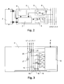
- Fig. 1 1 shows a battery 1 comprising a plurality of cells 2a..2n with cell monitoring units 3a..3n connected thereto and identically constructed, as well as a central monitoring unit 4.
- the cell monitoring units 3a..3n are connected to the central monitoring unit 4 via signal lines L1..L4.
- the central monitoring unit 4 is finally connected via a data bus B with further, not shown, control units.
- Fig. 2 shows a cell monitoring unit 3 from Fig. 1 , which is connected to a cell 2, in detail.
- the cell monitoring unit 3 comprises an input-side optocoupler 5 and an output-side optocoupler 6. Although these are advantageous for the invention but by no means mandatory, since the connection of the cell monitoring unit 3 to the signal lines L1..L4 can also be done via other means, for example via isolation transformers.
- the cell monitoring unit 3 further comprises a transducer 7 and a reference source 8.
- the transducer 7 is connected to the input side optocoupler 5, the output side opto-coupler 6 and the reference source 8.
- a current source 9 is arranged on the input side.
- Fig. 3 now shows the central monitoring unit 4 Fig. 1 in detail.
- This comprises a microcontroller 10, several comparators 11..14, three voltage sources 15..17, two resistors 18, 19, a switch 20 and diodes 21st
- a reference pulse sequence with a defined pulse duration (eg 0.5 ms) and a defined frequency (eg 1 kHz) is sent by the central monitoring unit 4 to all cell monitoring units 3a... 3n.
- the switch 20 is controlled by the microcontroller 10 in a corresponding manner periodically.
- the circuit between the voltage source 17, the power sources 9, the optocouplers 5 and the ground terminal is closed.
- the signal impressed on the switch 20 is sent to the cell monitoring units 3a..3n where it serves as reference pulse for the measuring transducer 7.
- the current in the second signal line L2 is shown, which represents a central reference or clock signal.
- Each cell monitoring unit 3a... 3n uses the reference source 8 and the reference pulse to generate a measuring pulse which is synchronous with the reference pulse and whose duration depends linearly on the measured value.
- the cell voltage is provided as a measurement parameter and a reference voltage source is provided as a reference source 8.
- Analog could be provided as a measured value, for example, the cell temperature and reference source 8 as a reference temperature source. Often a temperature is converted by a temperature sensor into a resistance or voltage. As reference source 8 can then accordingly Reference resistor or turn a reference voltage source or a reference power source serve.
- a pulse-width-modulated signal (PWM signal) is generated in the present example from a voltage signal.
- PWM signal pulse-width-modulated signal
- a rising / falling edge of a constant frequency periodic signal is shifted by 0.25 ms per volt deviation of the measured value from a reference value of 2V.
- the measured value used is therefore the deviation of a cell parameter from a reference value provided for each cell. This measuring pulse occurs predominantly in the pause between two reference pulses.
- the first line L1 is then alternately connected to the third line L3 or the first line L1 to the fourth line L4 via the output-side optocoupler 6. Because of the current source 9, a voltage signal is generated in the central monitoring unit 4 via the resistors 18 and 19. If several optocouplers 6 are actuated at the same time, the current sources 9 are connected in parallel and thus generate a summation current which manifests itself in an increased voltage value at the resistors 18 and 19. As a rule, the voltages of the cells 2a..2n are different, so that the optocouplers 6 are activated at different times because of the individual PWM signal. Thus, the summation of the PWM signals results in a step-shaped summation signal.
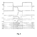
- Fig. 4 For this purpose, the currents IL3, IL4 are shown in the third signal line L3 and in the fourth signal line L4, each of which is formed from the individual measured values Show the sum signal.
- the sum signal on the line L3 is the "quasi-inverse" signal of the signal on the line L4.
- the transmission of a measured value thus takes place with the aid of a pulse-width-modulated signal, the pulse-width-modulated signals originating from the individual cells 2a..2n being transmitted and summing synchronously.
- each current source 8 supplies a different current, so that the concrete transmitting cell monitoring unit 3a..3n can be determined via the height of the resulting stage. It is particularly advantageous if the currents are coded binary, so that, for example, the current of the cell monitoring unit 3b is twice as large as the current of the cell monitoring unit 3a, the subsequent stream is four times as large, etc.
- the concrete transmitting cell monitoring unit 3a..3n can but also be determined in other ways, as will be explained below.
- the voltage curves U19 and U18 in Fig. 4 now show the due to the impressed current at the resistors 19 and 18 dropping voltage.
- U18 shows the quasi-magnified course of IL4 at low current values
- U19 the quasi-magnified course of IL3 at low current values.
- a voltage threshold or a voltage level U15 which corresponds to half the voltage, the voltage caused by a current source 8.
- a voltage threshold or a voltage level U16 is applied, which corresponds to the one and a half times the voltage caused by a current source 8 voltage.
- the comparator 14 If the voltage U18 now exceeds the first voltage level, then the comparator 14 generates a falling edge in its output voltage U14.
- the voltage signal U14 thus corresponds to the PWM signal of that cell monitoring unit 3a..3n, which has determined the lowest measured value within the accumulator 1.
- the comparator 13 If the voltage U18 now exceeds the second voltage level, the comparator 13 generates a falling edge in its output voltage U13.
- the voltage signal U13 thus corresponds to the PWM signal of that cell monitoring unit 3a..3n, which has determined the second-lowest measured value within the accumulator 1.
- the comparator 12 If the voltage U19 drops below the second voltage level U16, the comparator 12 generates a falling edge in its output voltage U12.
- the voltage signal U12 thus corresponds to the PWM signal of that cell monitoring unit 3a..3n, which has determined the second highest measured value within the accumulator 1. If the voltage U19 now falls below the first voltage level U15, then the comparator 11 generates a falling edge in its output voltage U11.
- the voltage signal U11 thus corresponds to the PWM signal of that cell monitoring unit 3a..3n, which has determined the highest measured value within the accumulator 1.
- the highest, the second-highest, the lowest and the second-lowest measured value can be detected simultaneously by the central monitoring unit 4.
- a step in the step-shaped signal IL3, IL4, U18, U19 resulting from the summation is thus interpreted in the central monitoring unit as the measured value of a cell 2a..2n, and at least one measured value is isolated from the sum signal IL3, IL4, U18, U19 .
- the first and / or the last stage in the staircase-shaped signal IL3, IL4, U18, U19 resulting from the summation is also interpreted in the central monitoring unit 4 as an extreme value of the measured parameter within the accumulator 1, and the respective measured value becomes the sum signal IL3, IL4, U18, U19 isolated.
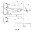
- Fig. 5 shows a further variant of the inventive accumulator 1. This is very similar to that in Fig. 1 accumulator 1 and comprises a plurality of cells 2a..2n with associated and similarly constructed cell monitoring units 3a..3n and a central monitoring unit 4.
- the cell monitoring units 3a..3n are via signal lines L1, L2 with the central Monitoring unit 4 connected.
- the central monitoring unit 4 is finally connected via a data bus B with further, not shown, control units.
- Fig. 6 is a cell monitoring unit 3 off Fig. 5 shown in detail.
- the cell monitoring unit 3 comprises an input-side optocoupler 5, a manipulated variable converter 22, a reference source 8, a cell controller 23, a transistor 24 and a resistor 25.
- a current source 9 is arranged on the input side.
- the manipulated variable converter 22 is connected to the input-side optocoupler 5, the reference source 8 and to the cell controller 23.
- the manipulated variable converter 22 is connected to the cell controller 23. This is finally connected to the cell 2 and controls a arranged between the terminals of the cell 2 series circuit of the transistor 24 and the resistor 25 at.
- the input-side optocoupler 5 is indeed as in the in Fig. 1 shown accumulator 1 advantageous for the invention but by no means mandatory, since the connection of the cell monitoring unit 3 to the signal lines L1..L2 can also be done via other means, for example via isolation transformers, input amplifiers and the like.
- Fig. 7 now shows the central monitoring unit 4 Fig. 5 in detail.
- This comprises a microcontroller 10, a voltage source 17 and a switch 20.
- the aim of this circuit variant is to compensate for differences between the individual cells 2a..2n with respect to a particular parameter.
- the individual cell voltages are to be matched to each other, it is also called "balancing".
- other cell parameters could be matched to one another, for example the cell temperature.
- the switch 20 is clocked accordingly and the signal is forwarded in such a way via the lines L1 and L2 to all cell monitoring units 3a..3n.
- the control signal is forwarded to the manipulated variable converter 22, which uses the reference source 8 (in the present example, a reference voltage source) from the PWM signal an actuating signal in the form of a level (in the present example, a voltage level).
- This voltage level is input as a setpoint to the cell controller 23, which compares it with the voltage measured at the terminals of the cell 2 and activates the transistor 24 when the cell voltage is too high. Via the resistor 25, the excess cell voltage is reduced and converted into heat.
- a nominal value for a cell temperature can also be preset, which is transmitted analogously to the nominal value for the cell voltage with the aid of a PWM signal. If the cell temperature is too low, then the transistor 24 is also activated to heat the cell 2. It should be for a good Heat transfer between cell 2 and resistor 25 are ensured.
- the measured voltage and the measured temperature to a connected to the terminals of a cell 2 and to the cell 2 thermally coupled heating (here in the form of the resistor 25) when exceeding a threshold value for the cell voltage or falls below a threshold for to activate the cell temperature.
- Fig. 1 illustrated variant of the invention and in Fig. 5 shown variant can also be combined with each other, so that there is a system that the functionality of the in the Fig. 1 shown circuit with the functionality of in the Fig. 5 united circuit shown.
- certain functions can also be shared. This is obvious, for example, with the input-side optocoupler 5, the reference source 8, the microcontroller 10, etc.
- the function of the transducer 7 and the manipulated variable converter 22 can be taken over by one and the same module, for example a voltage-PWM converter Measured value, times a control value is supplied as an input signal.
- the cell monitoring unit 3 essentially consists of a single one
- Be constructed block for example, a microcontroller, in which the individual functional blocks is formed by circuit parts of the microcontroller and / or corresponding software routines. Realization in the form of an ASIC (Application Specific Integrated Circuit) is also possible.
- ASIC Application Specific Integrated Circuit
- Fig. 8 shows a further variant of the inventive accumulator 1, which the in Fig. 1 shown accumulator is very similar. Instead of four lines L1..L4, however, there are seven lines L1..L7, additional D flip-flops 26a..26n, additional AND gates 27a..27n, additional switches 28a..28n and a modified central monitoring unit 4 , which in the following with reference to Fig. 9 is explained in more detail available.
- Fig. 9 shows the central monitoring unit 4 Fig. 8 which comprises a microcontroller 10, three comparators 11, 14 and 29, two voltage sources 15 and 17, two resistors 18, 19, a switch 20 and diodes 21.
- each cell monitoring unit 3a..3n At the output of each cell monitoring unit 3a..3n is a switch 28a..28n, with which the output of an output-side optocoupler 6 optionally between the fourth signal line L4 and the fifth signal line L5 switch over.
- the switches are controlled by the D flip-flops 26a..26n.
- a pulse-shaped reset signal on the line L7 resets all the D flip-flops 26a..26n so that their output Qa..Qn assumes the value zero. Shortly after the start of the reference pulse on line L2 (low active), the reset signal is set high (inactive); Thereby, the output of the cell monitoring unit 3n is switched to the fifth line L5.
- the switches 28a, 28n are thus activated one after the other individually by a type of shift register, which is formed by the concatenated D flip-flops 28a, 28n, so that all the PWM signals of the individual cells 2a..2n are successively transmitted individually via the signal line L5 can be transmitted and evaluated.
- the AND gates 27a, 27n serve for the correct control of the changeover switches 28a, 28n.
- the measured value transmitted in each case via the line L5 is evaluated individually via the comparator 28. Due to the time multiplex, no special addressing of the cell monitoring units 3a..3n is necessary, or is accomplished by this. Since the other measured values are still transmitted as a sum signal, however, the highest measured value within the sum signal can be determined from the sum signal via the comparator 11 and the lowest measured value within the sum signal can be determined via the comparator 14. In the microcontroller 10 can be further compared whether the individually transmitted via the line L5 measured value exceeds the highest value from the sum signal or falls below the lowest value from the sum signal.
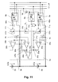
- Fig. 11 now shows a further variant of the invention.
- a cell monitoring unit 3a and partial cell monitoring unit 3b (not here as in the other figures below but above) is shown.
- Units are shown, which are provided for the adjustment of a reference value, here a reference voltage.
- the units represented in the previous figures in a cell monitoring unit 3a..3n may of course additionally be present in a real embodiment of a cell monitoring unit 3a..3n.
- This means a cell monitoring unit 3 can all in the Figures 2 . 6 and 10 contained units.
- the cell monitoring unit 3 a comprises an input-side optocoupler 5 a, an output-side optocoupler 6 a, a reference source 8 a (in the present case designed as a reference voltage source) and a current source 9 a. Furthermore, the cell monitoring unit 3a comprises an operational amplifier 30a, to whose positive input the reference voltage source 8a is connected, and which forms an integrator with the resistor 31a and the capacitor 32a. To the positive input of the operational amplifier 30a, a resistor 33a is further connected, which is provided for connection to a further cell monitoring unit.
- the Cell monitoring unit 3a an operational amplifier 34a, whose positive input is connected to the positive pole of the cell 2a, and which together with the resistors 35a and 33b forms a summing amplifier.
- the outputs of the operational amplifiers 30a and 34a are connected to a comparator 36a.
- the cell monitoring unit 3a also comprises a switch 37a, with which the input of the integrator can be switched to the negative pole of the cell 2a, and a switch 38a, with which the input of the integrator can be switched to the positive pole of the cell 2a.
- the cell monitoring unit 3a comprises a NOR gate 39a, to whose inputs the output of the input-side optocoupler 5a and the output of the comparator 36a are guided. The output of the NOR gate 39a is fed to the control input of the switch 37a and via a resistor 40a to the input of the output side opto-coupler 6a.
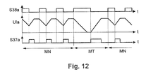
- Fig. 11 shows the timings of the input signal S37a of the switch 37a, the input signal S38a of the switch 38a, as well as the output voltage of the integrator UIa.
- the voltage UCa-URa is again negatively integrated with the aid of the integrator during the reference time T1.
- the switch 38a is closed again, the switch 37a open.
- the time T1 is chosen such that the output of the operational amplifier 30a reliably reaches zero and remains there even with a minimum cell voltage.
- the output-side optocoupler 6a is switched over and the reference voltage URa is positively integrated during the duration T2 until the comparator threshold UCa-URb is reached again.
- the switch 38a is open, the switch 37a is closed. Then the integration is stopped and the output signal becomes inactive again.
- the values for C32 can be stored, for example, during the first commissioning.
Landscapes
- Engineering & Computer Science (AREA)
- Power Engineering (AREA)
- Manufacturing & Machinery (AREA)
- Chemical & Material Sciences (AREA)
- Chemical Kinetics & Catalysis (AREA)
- Electrochemistry (AREA)
- General Chemical & Material Sciences (AREA)
- Physics & Mathematics (AREA)
- General Physics & Mathematics (AREA)
- Charge And Discharge Circuits For Batteries Or The Like (AREA)
- Investigating Or Analysing Biological Materials (AREA)
- Measurement Of Radiation (AREA)
Abstract
Description
Die Erfindung betrifft ein Verfahren zur Überwachung eines Akkumulators mit mehreren Zellen, bei dem ein Parameter einer Zelle gemessen und an eine zentrale Überwachungseinheit übermittelt wird. Weiterhin betrifft die Erfindung eine Zellüberwachungseinheit zum Überwachen einer Zelle eines Akkumulators, welche eine Messeinrichtung zur Messung eines Parameters der Zelle sowie eine Sendeeinrichtung zur Übermittlung des Messwertes umfasst. Zudem betrifft die Erfindung eine zentrale Überwachungseinheit zur Überwachung eines Akkumulators mit mehreren Zellen, umfassend eine Empfangseinrichtung zum Empfang eines Messwertes eines Parameters einer Zelle. Schliesslich betrifft die Erfindung einen Akkumulator mit mehreren Zellen, welcher je Zelle eine Zellüberwachungseinheit umfasst beziehungsweise mit diesen verbunden ist.The invention relates to a method for monitoring an accumulator having a plurality of cells, in which a parameter of a cell is measured and transmitted to a central monitoring unit. Furthermore, the invention relates to a cell monitoring unit for monitoring a cell of a rechargeable battery, which comprises a measuring device for measuring a parameter of the cell and a transmitting device for transmitting the measured value. In addition, the invention relates to a central monitoring unit for monitoring a rechargeable battery having a plurality of cells, comprising a receiving device for receiving a measured value of a parameter of a cell. Finally, the invention relates to an accumulator with a plurality of cells, which comprises a cell monitoring unit per cell or is connected thereto.
Akkumulatoren bilden die Energieversorgung der überwiegenden Mehrzahl elektrisch betriebener, mobiler Geräte. Um eine geforderte Nennspannung, einen geforderten Strom und/oder eine geforderte Kapazität zu erreichen, werden zumeist mehrere galvanische Zellen zu einem Akkumulator verbaut.Accumulators form the energy supply of the vast majority of electrically powered, mobile devices. In order to achieve a required nominal voltage, a required current and / or a required capacity, usually several galvanic cells are installed to form a storage battery.
Insbesondere bei Lithium-Ionen-Akkumulatoren und Lithium-Polymer-Akkumulatoren hat sich herausgestellt, dass die einzelnen Zellen bei der Entladung unterschiedliche Spannungslagen, beziehungsweise beim Laden mehrerer in Serie geschalteter Zellen ohne weitere Massnahmen unterschiedliche Ladezustände erreichen. Um ein für die Zelle schädliches Überladen oder Tiefentladen zu vermeiden und auch die Kapazität des Akkumulators optimal auszunutzen, werden die Zellen beim Laden einzeln kontrolliert. Dazu werden bei mehrzelligen Akkus für jede Zelle separate Anschlüsse bereitgestellt, die das individuelle Laden oder Entladen einer einzelnen Zelle gestatten. Das Ausgleichen dieser unterschiedlichen Zellspannungen beziehungsweise Ladezustände wird auch "Balancing" genannt.Particularly in the case of lithium-ion accumulators and lithium-polymer accumulators, it has been found that the individual cells achieve different states of charge when discharging different voltage levels, or when charging several series-connected cells without further measures. To be harmful to the cell To avoid overcharging or overdischarging and to make optimal use of the capacity of the accumulator, the cells are individually controlled during charging. For this, multi-cell batteries provide separate ports for each cell, allowing individual charging or discharging of a single cell. Balancing these different cell voltages or states of charge is also called "balancing".
Prinzipiell kann dieser Ausgleich durch gezieltes Entladen individueller Zellen, welche einen höheren Spannungspegel aufweisen, oder durch gezieltes Laden von Zellen, die einen zu niedrigen Spannungspegel aufweisen, erfolgen. Ersteres kann zum Beispiel mit Hilfe eines Widerstands erfolgen, über den die überschüssige Energie in Wärme umgewandelt wird. Beim gezielten Laden werden einzelne Zellen mit höherem Strom geladen oder es wird Energie von Zellen mit hohem Energieinhalt auf Zellen mit niedrigem Energieinhalt umgeladen.In principle, this compensation can take place by deliberately discharging individual cells which have a higher voltage level or by deliberately charging cells which have too low a voltage level. For example, the former can be done with the help of a resistor that converts excess energy into heat. Targeted charging charges individual cells with higher current or transfers energy from high-energy cells to low-energy cells.
Insbesondere bei Elektrokraftfahrzeugen - welche ja Akkumulatoren mit sehr hoher Kapazität aufweisen - haben sich im Laufe der Zeit zum Teil relativ komplexe Systeme herausgebildet, um einerseits die Kapazität des Akkumulators bestmöglich auszunutzen und um andererseits eine lange Lebensdauer zu gewährleisten. Beispielsweise ist dabei jeder Zelle eines Akkumulators eine Zellüberwachungseinheit zugeordnet, welche den Ladezustand, das Laden und das Entladen einer Zelle kontrolliert. Diese kommuniziert zumeist mit einer dem gesamten Akkumulator zugeordneten zentralen Überwachungseinheit, welche die Daten aller Zellüberwachungseinheiten sammelt und diese entsprechend ansteuert. Die zentrale Überwachungseinheit kommuniziert zumeist auch mit einer zentralen Fahrzeugsteuerung, welche zum Beispiel den Fahrer darüber informiert, für welche Wegstrecke der Akkumulator noch reicht. Selbstverständlich können dabei auch andere Parameter als die Zellspannung/Zellkapazität ermittelt beziehungsweise geregelt werden, beispielsweise die Zelltemperatur. Aus dem Stand der Technik sind einige Beispiele für solche Überwachungs-/Steuersysteme bekannt.In particular, in electric vehicles - which indeed have accumulators with very high capacity - over time, sometimes relatively complex systems have emerged to make the best possible use of the capacity of the battery and on the other hand to ensure a long life. By way of example, each cell of a rechargeable battery is assigned a cell monitoring unit which controls the state of charge, charging and discharging of a cell. This usually communicates with the entire accumulator associated central monitoring unit, which collects the data of all cell monitoring units and controls them accordingly. The central monitoring unit communicates usually also with a central vehicle control, which, for example, informs the driver for which distance the accumulator still reaches. Of course, it is also possible to determine or regulate parameters other than the cell voltage / cell capacity, for example the cell temperature. Some examples of such monitoring / control systems are known in the art.
Beispielsweise offenbart die
Die
Die
Die
Die
Schliesslich zeigt die
Nachteilig an den bekannten Systemen ist die zum Teil aufwändig gestaltete Kommunikation zwischen den den Zellen zugeordneten Zellüberwachungseinheiten und der dem Akkumulator zugeordneten zentralen Überwachungseinheit. Aufgabe der Erfindung ist es daher, ein verbessertes Verfahren und eine verbesserte Zellüberwachungseinheit zur Überwachung eines Akkumulators, sowie eine verbesserte zentrale Überwachungseinheit und einen verbesserten Akkumulator anzugeben. Insbesondere soll die Kommunikation zwischen den beteiligten Einheiten verbessert werden.A disadvantage of the known systems is the sometimes elaborate communication between the cell monitoring units assigned to the cells and the central monitoring unit assigned to the accumulator. The object of the invention is therefore to specify an improved method and an improved cell monitoring unit for monitoring a rechargeable battery, as well as an improved central monitoring unit and an improved rechargeable battery. In particular, the communication between the units involved should be improved.
Erfindungsgemäss wird diese Aufgabe durch ein Verfahren der eingangs genannten Art gelöst, bei dem die Übermittlung eines Messwerts mit Hilfe eines pulsweitenmodulierten Signals erfolgt.According to the invention, this object is achieved by a method of the type mentioned above, in which the transmission of a measured value takes place with the aid of a pulse-width-modulated signal.
Die Aufgabe der Erfindung wird weiterhin durch eine Zellüberwachungseinheit der eingangs genannten Art gelöst, bei der die Sendeeinrichtung zur Übermittlung des Messwertes mit Hilfe eines pulsweitenmodulierten Signals eingerichtet ist.The object of the invention is further achieved by a cell monitoring unit of the type mentioned, in which the transmitting device is set up to transmit the measured value with the aid of a pulse-width-modulated signal.
Zudem wird die Aufgabe der Erfindung durch eine zentrale Überwachungseinheit der eingangs genannte Art gelöst, bei dem die Übermittlung des Messwerts mit Hilfe eines pulsweitenmodulierten Signals erfolgt.In addition, the object of the invention is achieved by a central monitoring unit of the type mentioned, in which the transmission of the measured value takes place with the aid of a pulse-width-modulated signal.
Schliesslich wird die Aufgabe der Erfindung durch einen Akkumulator mit mehreren Zellen gelöst, welcher je Zelle eine erfindungsgemässe Zellüberwachungseinheit umfasst beziehungsweise mit dieser verbunden ist.Finally, the object of the invention is achieved by a rechargeable battery having a plurality of cells, which cell per cell comprises a cell monitoring unit according to the invention or is connected thereto.
Mit Hilfe der eines pulsweitenmodulierten Signals (PWM-Signals) lassen sich Messwerte auch über weitere Strecken, beziehungsweise in einem hinsichtlich der elektromagnetischen Felder problematischen Umfeld sicher, das heisst weitgehend unverfälscht, übertragen. Dabei wird ein Messwert in ein Tastverhältnis eines Pulses mit konstanter Frequenz umgewandelt. Insbesondere gegenüber Systemen, welche Messwerte analog übertragen, beispielsweise über eine Stromschleife, stellt dies einen erheblichen Fortschritt dar, da analog übertragene Messwerte aufgrund der in einem Elektrokraftfahrzeug herrschenden elektromagnetischen Felder - beispielsweise verursacht durch den Antriebsmotor oder durch einen Wechselrichter - leicht verfälscht werden können. Aber auch gegenüber bekannten Systemen, bei denen Messwerte bereits digital übertragen werden, stellt die Erfindung einen Fortschritt dar, da ein Spannungs-PWM-Umsetzer, welcher in einer Zellüberwachungseinheit häufig ohnehin zum Ansteuern eines "Shunts" für das Balancing vorhanden ist, nun einen Doppelnutzen erfüllen kann. Erfindungsgemäss erhält dieser nicht nur Spannungssignale von einer zentralen Überwachungseinheit, die zur Erzeugung eines PWM-Signals für den Shunt herangezogen werden, sondern kann nun auch die Zellspannung in ein PWM-Signal umsetzten und solcherart zur zentralen Überwachungseinheit übermitteln. Selbstverständlich können für diese Aufgabe auch zwei getrennte PMW-Umsetzer verwendet werden.With the aid of a pulse-width-modulated signal (PWM signal), measured values can also be reliably determined over longer distances or in a problematic environment with regard to the electromagnetic fields, that is to say largely unadulterated, transmitted. In this case, a measured value is converted into a duty cycle of a pulse with a constant frequency. In particular, compared to systems which transmit measured values analogously, for example via a current loop, this represents a considerable advance since measured values transmitted analogously can easily be falsified due to the electromagnetic fields prevailing in an electric motor vehicle, for example caused by the drive motor or by an inverter. But even with respect to known systems in which measured values are already transmitted digitally, the invention represents an advance, since a voltage-PWM converter, which is often present anyway in a cell monitoring unit for driving a "shunt" for balancing, now has a double benefit can fulfill. According to the invention, this not only receives voltage signals from a central monitoring unit, which are used to generate a PWM signal for the shunt, but can now also convert the cell voltage into a PWM signal and thus transmit it to the central monitoring unit. Of course, two separate PMW converters can be used for this task.
Vorteilhafte Ausgestaltungen und Weiterbildungen der Erfindung ergeben sich nun aus den Unteransprüchen sowie aus der Beschreibung in Zusammenschau mit den Figuren der Zeichnung bzw. sind durch sie geoffenbart.Advantageous embodiments and developments of the invention will become apparent from the dependent claims and from the description in conjunction with the figures of the drawing or are disclosed by them.
Vorteilhaft ist es, wenn die von den einzelnen Zellen stammenden pulsweitenmodulierten Signale synchron übermittelt und summiert werden. Auf diese Weise können die Messwerte aller Zellüberwachungseinheiten auf einmal, das heisst während einer einzigen Messwertübertragung, zur zentralen Überwachungseinheit übermittelt werden. Das Senden der Messwerte erfolgt also besonders schnell, ohne dass dafür - wie beim sequentiellen Senden von Messwerten - relativ hohe Taktfrequenzen für die Datenübermittlung nötig wären.It is advantageous if the pulse-width-modulated signals originating from the individual cells are synchronously transmitted and summed. In this way, the measured values of all cell monitoring units at once, that is, during a single measured value transmission, can become the central one Monitoring unit to be transmitted. The transmission of the measured values thus takes place particularly quickly, without the need for relatively high clock frequencies for the data transmission, as is the case with the sequential transmission of measured values.
Vorteilhaft ist es in diesem Zusammenhang, wenn eine Stufe in dem durch die Summierung entstandenen treppenförmigen Signal in der zentralen Überwachungseinheit als Messwert einer Zelle interpretiert und der Messwert aus dem Summensignal isoliert wird. Wenn bekannt ist, wie hoch eine durch einen Messwert verursachte Stufe in dem treppenförmigen Summensignal ist, dann kann aus der Anordnung und Höhe der Stufen auf die Höhe der Messwerte und deren Verteilung geschlossen werden. Aus dem Summensignal kann auch ein einzelner Messwert isoliert werden.It is advantageous in this connection if a step in the step-shaped signal resulting from the summation in the central monitoring unit is interpreted as the measured value of a cell and the measured value is isolated from the summation signal. If it is known how high a step caused by a measured value is in the step-shaped summation signal, then it is possible to deduce the height of the measured values and their distribution from the arrangement and height of the steps. From the sum signal also a single measured value can be isolated.
Besonders vorteilhaft ist es, wenn die erste und/oder letzte Stufe in dem durch die Summierung entstandenem treppenförmigen Signal in der zentralen Überwachungseinheit als Extremwert des gemessenen Parameters innerhalb des Akkumulators interpretiert und der Messwert aus dem Summensignal isoliert wird. Die erste und die letzte Stufe in dem Summensignal entsprechen den im Akkumulator auftretenden Extremwerten. Wird als Messparameter beispielsweise die Zellspannung vorgesehen, dann entsprechen die erste und die letzte Stufe der niedrigsten beziehungsweise höchsten Zellspannung innerhalb des Akkumulators. Mit dieser Variante der Erfindung können also sehr rasch innerhalb eines Akkumulators auftretende Extremwerte festgestellt werden.It is particularly advantageous if the first and / or last stage in the step-shaped signal produced by the summation in the central monitoring unit is interpreted as an extreme value of the measured parameter within the accumulator and the measured value is isolated from the summation signal. The first and the last stage in the sum signal correspond to the extreme values occurring in the accumulator. If, for example, the cell voltage is provided as the measurement parameter, then the first and the last stage correspond to the lowest or highest cell voltage within the accumulator. With this variant of the invention, therefore, extreme values occurring within a rechargeable battery can be detected very quickly.
Vorteilhaft ist, wenn in der zentralen Überwachungseinheit für die Isolation eines Messwertes detektiert wird, ob das treppenförmige Signal einen zwischen zwei Stufen vorgegeben Pegelwert passiert. Wenn die Höhe der durch einen Messwert verursachten Stufe bekannt ist, dann kann ein Pegelwert zwischen zwei horizontalen (wenn die Zeit auf der horizontalen Achse aufgetragen ist) beziehungsweise vertikalen (wenn die Zeit auf der vertikalen Achse aufgetragen ist) Abschnitten der Stufen gesetzt werden und abgewartet werden, bis das Summensignal diesen Pegelwert passiert. Der Zeitpunkt des Passierens gibt das Tastverhältnis des diesem Messwert zugeordneten PWM-Signals und damit den Messwert selbst an.It is advantageous if it is detected in the central monitoring unit for the isolation of a measured value, whether the step-shaped signal one between two levels specified Level value happens. If the level of the level caused by a measurement is known, then a level value between two horizontal (when the time is plotted on the horizontal axis) and vertical (when the time is plotted on the vertical axis) sections of the levels can be set and awaited until the sum signal passes this level value. The time of passing indicates the duty cycle of the PWM signal associated with this measured value and thus the measured value itself.
Besonders vorteilhaft ist auch eine Variante des erfindungsgemässen Verfahrens, bei der zeitlich nacheinander jeweils ein Messwert individuell an die zentrale Überwachungseinheit übermittelt wird. Wenn die durch die einzelnen Messwerte verursachten Stufen alle dieselbe Höhe haben, dann ist zwar eine simultane Übermittlung aller Messwerte möglich, jedoch kann ein bestimmter Messwert nicht einer bestimmten Zelle zugeordnet werden. Bei dieser Variante der Erfindung wird aber sequentiell ein Messwert individuell übertragen, sodass in der zentralen Überwachungseinheit auch bekannt ist, welcher Messwert konkret welcher Zelle zugeordnet ist.Also particularly advantageous is a variant of the method according to the invention, in which in each case one measured value is transmitted individually to the central monitoring unit one after the other. If the levels caused by the individual measured values all have the same height, then a simultaneous transmission of all measured values is possible, but a specific measured value can not be assigned to a specific cell. In this variant of the invention, however, a measured value is transmitted individually in a sequential manner, so that it is also known in the central monitoring unit which measured value is concretely assigned to which cell.
In diesem Zusammenhang ist es vorteilhaft, wenn der individuell an die zentrale Überwachungseinheit übermittelte Messwert parallel zum Summensignal übermittelt wird. Bei dieser Variante der Erfindung werden parallel zum individuell übertragenen Messwert alle übrigen Messwerte in Form eines Summensignals übertragen, sodass bei jeder Messwertübertragung zusätzlich zu einem individuellen Messwert die in einem Akkumulator auftretenden Extremwerte festgestellt werden können.In this context, it is advantageous if the measured value transmitted individually to the central monitoring unit is transmitted in parallel to the sum signal. In this variant of the invention, all other measured values are transmitted in the form of a sum signal parallel to the individually transmitted measured value, so that the extreme values occurring in an accumulator can be ascertained for each measured value transmission in addition to an individual measured value.
In diesem Zusammenhang ist es zudem von Vorteil, wenn der individuell an die zentrale Überwachungseinheit übermittelte Messwert aus der Summierung ausgenommen wird. Bei dieser Variante der Erfindung wird der individuell übermittelte Messwert aus der Summierung ausgenommen, um eine redundante Übermittlung von Messwerten zu vermeiden.In this context, it is also advantageous if the measured value transmitted individually to the central monitoring unit is excluded from the summation. In this variant of the invention, the individually transmitted measured value is excluded from the summation in order to avoid a redundant transmission of measured values.
Günstig ist es, wenn als Messwert die Abweichung des Zellparameters von einem je Zelle vorgesehen Referenzwert herangezogen wird. Um den Messwert mit möglichst guter Auflösung ermitteln zu können, wird bei dieser Variante der Erfindung eine Abweichung des Zellparameters von einem Referenzwert übermittelt. Auf diese Weise kann zum Beispiel ein ohnehin immer oder zumindest häufig vorhandener "Offset" abgezogen werden. Wird beispielsweise die Zelltemperatur als Zellparameter herangezogen, so kann z.B. die Abweichung der Temperatur von 20°C als Messwert übermittelt werden, da 20° die Norm darstellt und Werte unter -20° und +80° eher selten auftreten dürften. Der solcherart auf ΔT=100°C beschränkte Bereich kann somit mit guter Messwertauflösung übermittelt werden. Messwerte ausserhalb des Bereichs werden als Messwertüberlauf übermittelt.It is advantageous if the deviation of the cell parameter from a reference value provided for each cell is used as the measured value. In order to be able to determine the measured value with the best possible resolution, a deviation of the cell parameter from a reference value is transmitted in this variant of the invention. In this way, for example, an always or at least frequently existing "offset" can be subtracted. For example, if the cell temperature is used as a cell parameter, e.g. the deviation of the temperature of 20 ° C as a measured value are transmitted, since 20 ° represents the norm and values under -20 ° and + 80 ° are likely to occur rarely. The range thus limited to ΔT = 100 ° C can thus be transmitted with good measured value resolution. Measured values outside the range are transmitted as measured value overflow.
Vorteilhaft ist es auch, wenn
- für die Erfassung von Messwerten verwendete und je Zelle vorgesehene Referenzwerte benachbarter Zellen periodisch wiederkehrend miteinander verglichen werden, und
- eine Fehlermeldung ausgegeben wird, wenn die Abweichung einen vorgebbaren Grenzwert überschreitet.
- and periodically recurring reference values of adjacent cells used for the acquisition of measured values and provided for each cell, and
- an error message is output if the deviation exceeds a predefinable limit value.
Häufig werden für die Ermittlung von Messwerten Referenzwerte benötigt. Beispielsweise kann in einer Zellüberwachungseinheit eine Referenzspannungsquelle vorgesehen sein, wenn die Zellspannung als Messparameter herangezogen wird. Um eine (unerwünschte) Veränderung dieses Spannungsnormals erkennen zu können, wird der Referenzwert einer Zellüberwachungseinheit mit einem Referenzwert einer anderen Zellüberwachungseinheit verglichen. Tritt eine unerwartet hohe Abweichung auf, so ist vermutlich eine der beiden Referenznormale defekt. "Benachbart" bedeutet in diesem Zusammenhang nicht zwingend örtlich benachbart sondern "elektrisch" benachbart. Beispielsweise sind zwei elektrisch miteinander verbundene Zellen "elektrisch" benachbart, müssen aber nicht in unmittelbarer örtlicher Nähe angeordnet sein.Frequently reference values are required for the determination of measured values. For example, in a cell monitoring unit, a reference voltage source be provided when the cell voltage is used as a measurement parameter. In order to be able to detect an (undesired) change in this voltage standard, the reference value of one cell monitoring unit is compared with a reference value of another cell monitoring unit. If an unexpectedly high deviation occurs, one of the two reference standards is probably defective. "Adjacent" in this context does not necessarily mean locally adjacent but "electrically" adjacent. For example, two electrically interconnected cells are "electrically" adjacent, but need not be located in close proximity to each other.
An dieser Stelle wird darauf hingewiesen, dass die oben genannte Variante der Erfindung auch ohne die zu den übrigen Varianten genannten Merkmalen vorteilhaft sein und damit die Basis einer unabhängigen Erfindung bilden kann.It should be noted at this point that the abovementioned variant of the invention may also be advantageous without the features mentioned in relation to the other variants and thus form the basis of an independent invention.
Günstig ist es, wenn als Parameter die Spannung und/oder die Temperatur der Zelle vorgesehen ist. Diese beiden Parameter sind besonders aussagekräftig für eine Zelle. Beispielsweise kann durch Überwachen der Zellspannung ein Überladen oder Tiefentladen derselben vermieden werden. Gleichermassen kann durch Überwachung der Temperatur der Zelle ein Betrieb ausserhalb eines zulässigen oder optimalen Betriebsbereichs verhindert werden.It is favorable if the voltage and / or the temperature of the cell is provided as a parameter. These two parameters are particularly meaningful for a cell. For example, by monitoring the cell voltage, overcharging or over-discharging thereof can be avoided. Likewise, by monitoring the temperature of the cell, operation outside of an allowable or optimum operating range can be prevented.
Besonders vorteilhaft ist es, wenn die gemessene Spannung und die gemessene Temperatur dazu herangezogen werden, eine mit den Klemmen einer Zelle verbundene und an die Zelle thermisch gekoppelte Heizung bei Überschreiten eines Grenzwertes für die Zellspannung oder bei Unterschreiten eines Grenzwertes für die Zelltemperatur zu aktivieren. Bei dieser Variante wird ein parallel zur Zelle angeordneter Widerstand ("Shunt") nicht nur dazu verwendet, eine Zelle bei Überspannung gezielt zu entladen, also das Balancing zu bewerkstelligen, sondern auch dazu, um die Zelle bei zu geringer Temperatur zu erwärmen. Eine Zelle kann bei zu geringer Temperatur in der Regel nur eine reduzierte Leistung abgeben, weswegen es unter Umständen sinnvoll ist, die Zelle vor dem Einsatz auf Betriebstemperatur zu bringen. Bei dieser Variante der Erfindung wird dazu der häufig ohnehin für das Balancing vorhandene Shunt verwendet, der solcherart einen Doppelnutzen erbringt. Um eine optimale Heizwirkung zu erzielen sollte die thermische Kopplung zwischen Zelle und Shunt entsprechend ausgeführt sein, beispielsweise unter Zuhilfenahme von Wärmeleitpasten, einer Luftumwälzung und dergleichen.It is particularly advantageous if the measured voltage and the measured temperature are used to activate a heating connected to the terminals of a cell and thermally coupled to the cell when a limit value for the cell voltage or a cell temperature limit is exceeded. In this variant, a parallel to the cell arranged resistor ("shunt") Not only used to unload a cell in case of overvoltage, so to do the balancing, but also to heat the cell at too low a temperature. A cell can usually deliver only a reduced power at too low a temperature, so it may be useful to bring the cell to operating temperature before use. In this variant of the invention, the shunt, which is frequently used anyway for balancing, is used for this purpose, which in this way provides a double benefit. In order to achieve an optimum heating effect, the thermal coupling between cell and shunt should be designed accordingly, for example with the aid of thermal paste, an air circulation and the like.
An dieser Stelle wird darauf hingewiesen, dass die oben genannte Variante der Erfindung auch ohne die zu den übrigen Varianten genannten Merkmalen vorteilhaft sein und damit die Basis einer unabhängigen Erfindung bilden kann.It should be noted at this point that the abovementioned variant of the invention may also be advantageous without the features mentioned in relation to the other variants and thus form the basis of an independent invention.
Vorteilhaft ist es bei obiger Variante, wenn die Heizung so geregelt wird, dass die Zellspannung und/oder die Zelltemperatur einen vorgegebenen Sollwert oder einen Sollbereich einhält. Bei dieser Variante der Erfindung werden also nicht nur Grenzwerte im Sinne einer maximalen Zellspannung und/oder einer minimalen Zelltemperatur vorgegeben, sondern es wird ein Sollwert oder ein Sollbereich für einen Zellparameter vorgegeben. Das heißt es wird beispielsweise eine Soll-Zellspannung beziehungsweise eine minimale und eine maximale Zellspannung und/oder eine Soll-Zelltemperatur beziehungsweise eine minimale und eine maximale Zelltemperatur vorgegeben.It is advantageous in the above variant, if the heating is controlled so that the cell voltage and / or the cell temperature maintains a predetermined setpoint or a desired range. In this variant of the invention, therefore, not only limit values in the sense of a maximum cell voltage and / or a minimum cell temperature are predetermined, but a desired value or a nominal range for a cell parameter is predetermined. That is, for example, a desired cell voltage or a minimum and a maximum cell voltage and / or a desired cell temperature or a minimum and a maximum cell temperature is predetermined.
Vorteilhaft ist es bei einer Regelung eines Zellparameters auch, wenn die Übermittlung eines Sollwerts mit Hilfe eines pulsweitenmodulierten Signals erfolgt. Bei dieser Variante der Erfindung wird ein Sollwert von der zentralen Überwachungseinheit mit Hilfe eines PWM-Signals an die Zellüberwachungseinheit übermittelt, analog zur Messwertübermittlung von einer Zellüberwachungseinheit zu der zentralen Überwachungseinheit. Vorteilhaft kann so die für die Messwertübertragung ohnehin vorhandene Struktur (Messwertumformer, Datenleitungen, usw.) auch für die Übermittlung eines Sollwerts genutzt werden. Vorteilhaft ist dabei auch, dass ein Sollwert an mehrere Zellüberwachungseinheiten gleichzeitig gesendet werden kann und dieser dort lokal zur Ermittlung eines Stellwertes verwendet wird, die eigentliche Regelung also in der Zellüberwachungseinheit stattfindet. Dies steht im Gegensatz zu den aus dem Stand der Technik bekannten Lösungen, bei denen die zentrale Überwachungseinheit für jede Zellüberwachungseinheit gesonderte Stellwerte ermittelt und in Folge individuell übermittelt, die eigentliche Regelung also in der zentralen Überwachungseinheit erfolgt. Letzteres erfordert eine vergleichsweise komplexe Kommunikation zwischen der zentralen Überwachungseinheit und den Zellüberwachungseinheiten, wohingegen bei der erfindungsgemässen Variante mit relativ geringen Datenmengen das Auslangen für eine Regelung eines Zellparameters, insbesondere der Zellspannung und/oder der Zelltemperatur, gefunden werden kann.It is also advantageous in the case of a control of a cell parameter if the transmission of a desired value takes place with the aid of a pulse-width-modulated signal. In this variant of the invention, a desired value is transmitted from the central monitoring unit with the aid of a PWM signal to the cell monitoring unit, analogously to the transmission of measured values from a cell monitoring unit to the central monitoring unit. Advantageously, the structure already present for the measured value transmission (transducer, data lines, etc.) can thus also be used for the transmission of a desired value. It is also advantageous that a desired value can be sent to several cell monitoring units at the same time and this is used there locally to determine a control value, ie the actual regulation takes place in the cell monitoring unit. This is in contrast to the solutions known from the prior art, in which the central monitoring unit determines separate control values for each cell monitoring unit and transmits them individually as a result, ie the actual control takes place in the central monitoring unit. The latter requires a comparatively complex communication between the central monitoring unit and the cell monitoring units, whereas in the variant according to the invention with relatively small amounts of data, the sufficiency for controlling a cell parameter, in particular the cell voltage and / or the cell temperature, can be found.
Zudem wird angemerkt, dass sich die zum erfindungsgemässen Verfahren genannten Varianten und die daraus resultierenden Vorteile gleichermassen auf die erfindungsgemässe Zellüberwachungseinheit, die erfindungsgemässen zentrale Überwachungseinheit und den erfindungsgemässen Akkumulator beziehen und umgekehrt.In addition, it should be noted that the variants mentioned for the method according to the invention and the resulting advantages are equally applicable to the cell monitoring unit according to the invention, the central point according to the invention Obtain monitoring unit and the inventive accumulator and vice versa.
Schliesslich wird angemerkt, dass sich das erfindungsgemässe Verfahren beziehungsweise die erfindungsgemässe Zellüberwachungseinheit sowie die erfindungsgemässen zentrale Überwachungseinheit in Software und/oder in Hardware realisieren lässt. Wird die Erfindung in Software realisiert, dann führt ein Programm, welches in einem Mikroprozessor beziehungsweise Mikrocontroller abläuft, die erfindungsgemässen Schritte aus. Selbstverständlich kann die Erfindung auch bloss in Hardware umgesetzt werden, beispielsweise mit einem ASIC (Application Specific Integrated Circuit). Letzterer kann aber auch einen Prozessor beinhalten. Schliesslich kann ein Teil der Erfindung in Software, ein anderer Teil in Hardware umgesetzt werden.Finally, it is noted that the method according to the invention or the cell monitoring unit according to the invention and the central monitoring unit according to the invention can be implemented in software and / or in hardware. If the invention is implemented in software, then a program which runs in a microprocessor or microcontroller carries out the steps according to the invention. Of course, the invention can also be implemented only in hardware, for example with an ASIC (Application Specific Integrated Circuit). The latter can also include a processor. Finally, one part of the invention can be implemented in software, another part in hardware.
Die obigen Ausgestaltungen und Weiterbildungen der Erfindung lassen sich auf beliebige Art und Weise kombinieren.The above embodiments and developments of the invention can be combined in any manner.
Die vorliegende Erfindung wird nachfolgend anhand der in den schematischen Figuren der Zeichnung angegebenen Ausführungsbeispiele näher erläutert. Es zeigen dabei:
- Fig. 1
- schematisch eine Übersichtsdarstellung eines ersten erfindungsgemässen Akkumulators;
- Fig. 2
- eine Detaildarstellung einer ersten erfindungsgemässen Zellüberwachungseinheit;
- Fig. 3
- eine Detaildarstellung einer ersten zentralen Überwachungseinheit;
- Fig. 4
- den zeitlichen Verlauf verschiedener in einem erfindungsgemässen Akkumulator auftretenden Signale, insbesondere ein aus einzelnen Messwerten gebildetes Summensignal;
- Fig. 5
- schematisch eine Übersichtsdarstellung einer zweiten Variante eines erfindungsgemässen Akkumulators;
- Fig. 6
- eine Detaildarstellung einer zweiten erfindungsgemässen Zellüberwachungseinheit;
- Fig. 7
- eine Detaildarstellung einer zweiten zentralen Überwachungseinheit;
- Fig. 8
- schematisch eine Übersichtsdarstellung einer weiteren Variante eines erfindungsgemässen Akkumulators;
- Fig. 9
- eine Detaildarstellung einer weiteren zentralen Überwachungseinheit;
- Fig. 10
- den zeitlichen Verlauf verschiedener in dem erfindungsgemässen Akkumulator gemäss
Fig. 8 auftretenden Signale; - Fig. 11
- eine beispielhafte Schaltung zur Überwachung einer Referenzquelle einer Zellüberwachungseinheit und
- Fig. 12
- den zeitlichen Verlauf verschiedener in der Schaltung gemäss
Fig. 11 auftretenden Signale.
- Fig. 1
- schematically an overview of a first inventive battery;
- Fig. 2
- a detailed representation of a first inventive cell monitoring unit;
- Fig. 3
- a detailed representation of a first central monitoring unit;
- Fig. 4
- the time course of various signals occurring in an accumulator according to the invention, in particular a sum signal formed from individual measured values;
- Fig. 5
- schematically an overview of a second variant of an inventive accumulator;
- Fig. 6
- a detailed representation of a second inventive cell monitoring unit;
- Fig. 7
- a detailed representation of a second central monitoring unit;
- Fig. 8
- schematically an overview of a further variant of an inventive accumulator;
- Fig. 9
- a detailed representation of another central monitoring unit;
- Fig. 10
- the time course of various in the inventive accumulator according to
Fig. 8 occurring signals; - Fig. 11
- an exemplary circuit for monitoring a reference source of a cell monitoring unit and
- Fig. 12
- the time course of various in the circuit according to
Fig. 11 occurring signals.
In den Figuren der Zeichnung sind gleiche und ähnliche Teile mit gleichen Bezugszeichen und funktionsähnliche Elemente und Merkmale - sofern nichts Anderes ausgeführt ist - mit gleichen Bezugszeichen aber unterschiedlichen Indizes versehen.In the figures of the drawing are the same and similar parts with the same reference numerals and functionally similar elements and features - unless otherwise stated - provided with the same reference numerals but different indices.
Die Funktion des erfindungsgemässen Akkumulators 1 wird nun anhand der
Über die zweite Signalleitung L2 wird von der zentralen Überwachungseinheit 4 eine Referenzpuls-Folge mit definierter Pulsdauer (z.B. 0,5ms) und definierter Frequenz (z.B. 1kHz) an alle Zellüberwachungseinheiten 3a..3n gesendet. Dazu wird der Schalter 20 vom Mikrocontroller 10 in entsprechender Weise periodisch angesteuert. Beim Schliessen des Schalters 20 wird der Stromkreis zwischen der Spannungsquelle 17, den Stromquellen 9, den Optokopplern 5 und dem Masseanschluss geschlossen. Auf diese Weise wird das dem Schalter 20 aufgeprägte Signal in die Zellüberwachungseinheiten 3a..3n gesendet und dient dort als Referenzpuls für die Messwertumformer 7. In
Jede Zellüberwachungseinheit 3a..3n erzeugt mithilfe der Referenzquelle 8 und dem Referenzpuls einen zum Referenzpuls synchronen Mess-Impuls, dessen Dauer linear vom Messwert abhängt. Im vorliegenden Beispiel ist als Messparameter die Zellspannung und als Referenzquelle 8 entsprechend eine Referenzspannungsquelle vorgesehen. Analog könnte als Messwert beispielsweise auch die Zelltemperatur und als Referenzquelle 8 eine Referenztemperaturquelle vorgesehen sein. Häufig wird eine Temperatur von einem Temperatursensor in einen Widerstandswert oder eine Spannung umgewandelt. Als Referenzquelle 8 kann dann entsprechend ein Referenzwiderstand oder wiederum eine Referenzspannungsquelle oder eine Referenz-Stromquelle dienen.Each
Mit Hilfe des Messwertumformers 7 wird im vorliegenden Beispiel aus einem Spannungssignal ein pulsweitenmoduliertes Signal (PWM-Signal) generiert. Beispielsweise wird eine steigende/fallende Flanke eines periodischen Signals mit konstanter Frequenz um 0,25ms pro Volt Abweichung des Messwerts von einem Referenzwert von 2V verschoben. Als Messwert wird also die Abweichung eines Zellparameters von einem je Zelle vorgesehen Referenzwert herangezogen. Dieser Messimpuls erfolgt vorwiegend in der Pause zwischen zwei Referenzpulsen.With the aid of the measured
Über den ausgangsseitigen Optokoppler 6 wird sodann abwechselnd die erste Leitung L1 mit der dritten Leitung L3 oder die erste Leitung L1 mit der vierten Leitung L4 verbunden. Wegen der Stromquelle 9 wird über die Widerstände 18 und 19 ein Spannungssignal in der zentralen Überwachungseinheit 4 erzeugt. Werden mehrere Optokoppler 6 gleichzeitig betätigt, dann werden die Stromquellen 9 parallel geschalten und erzeugen so einen Summenstrom, welcher sich in einem erhöhten Spannungswert an den Widerständen 18 und 19 äussert. In der Regel sind die Spannungen der Zellen 2a..2n unterschiedlich, sodass die Optokoppler 6 wegen des jeweils individuellen PWM-Signals zu verschiedenen Zeitpunkten aktiviert werden. Somit resultiert durch die Summierung der PWM-Signale ein treppenförmiges Summensignal.The first line L1 is then alternately connected to the third line L3 or the first line L1 to the fourth line L4 via the output-
In
Die Übermittlung eines Messwerts erfolgt also mit Hilfe eines pulsweitenmodulierten Signals, wobei die von den einzelnen Zellen 2a..2n stammenden pulsweitenmodulierten Signale synchron übermittelt und summiert werden.The transmission of a measured value thus takes place with the aid of a pulse-width-modulated signal, the pulse-width-modulated signals originating from the
Im vorliegenden Fall wird angenommen, dass alle Stromquellen 8 denselben Strom liefern. Die einzelnen Stufen sind daher - vorausgesetzt jede Stromquelle wird zu einem anderen Zeitpunkt aktiviert - gleich hoch. Denkbar ist aber auch, dass jede Stromquelle 8 einen anderen Strom liefert, sodass über die Höhe der entstandenen Stufe die konkret sendende Zellüberwachungseinheit 3a..3n ermittelt werden kann. Besonders vorteilhaft ist es dabei, wenn die Ströme binär kodiert sind, sodass beispielsweise der Strom der Zellüberwachungseinheit 3b doppelt so gross ist wie der Strom der Zellüberwachungseinheit 3a, der darauf folgende Strom viermal so gross ist usw. Die konkret sendende Zellüberwachungseinheit 3a..3n kann aber auch auf andere Weise ermittelt werden, wie nachfolgend noch erläutert wird.In the present case, it is assumed that all
Die Spannungsverläufe U19 und U18 in
Mit Hilfe der Spannungsquelle 15 wird an die Komparatoren 11 und 14 ein Spannungsschwellwert beziehungsweise ein Spannungspegel U15 angelegt, welche der halben Spannung, der von einer Stromquelle 8 verursachten Spannung entspricht. Analog wird mit Hilfe der Spannungsquelle 16 an die Komparatoren 12 und 13 ein Spannungsschwellwert beziehungsweise ein Spannungspegel U16 angelegt, welche der eineinhalbfachen Spannung, der von einer Stromquelle 8 verursachten Spannung entspricht.With the aid of the
Überschreitet die Spannung U18 nun den ersten Spannungspegel, so erzeugt der Komparator 14 eine fallende Flanke in seiner Ausgangspannung U14. Das Spannungssignal U14 entspricht somit dem PWM-Signal jener Zellüberwachungseinheit 3a..3n, welche den niedrigsten Messwert innerhalb des Akkumulators 1 ermittelt hat. Überschreitet die Spannung U18 nun den zweiten Spannungspegel, so erzeugt der Komparator 13 eine fallende Flanke in seiner Ausgangspannung U13. Das Spannungssignal U13 entspricht somit dem PWM-Signal jener Zellüberwachungseinheit 3a..3n, welche den zweit-niedrigsten Messwert innerhalb des Akkumulators 1 ermittelt hat.If the voltage U18 now exceeds the first voltage level, then the
Unterschreitet die Spannung U19 den zweiten Spannungspegel U16, so erzeugt der Komparator 12 eine fallende Flanke in seiner Ausgangspannung U12. Das Spannungssignal U12 entspricht somit dem PWM-Signal jener Zellüberwachungseinheit 3a..3n, welche den zweit-höchsten Messwert innerhalb des Akkumulators 1 ermittelt hat. Unterschreitet die Spannung U19 nun den ersten Spannungspegel U15, so erzeugt der Komparator 11 eine fallende Flanke in seiner Ausgangspannung U11. Das Spannungssignal U11 entspricht somit dem PWM-Signal jener Zellüberwachungseinheit 3a..3n, welche den höchsten Messwert innerhalb des Akkumulators 1 ermittelt hat.If the voltage U19 drops below the second voltage level U16, the
Vorteilhaft können so innerhalb eines Messzyklus simultan der höchste, der zweit-höchste, der niedrigste und der zweitniedrigste Messwert von der zentralen Überwachungseinheit 4 erfasst werden.Advantageously, within a measuring cycle, the highest, the second-highest, the lowest and the second-lowest measured value can be detected simultaneously by the
Eine Stufe in dem durch die Summierung entstandenen treppenförmigen Signal IL3, IL4, U18, U19 wird in der zentralen Überwachungseinheit also als Messwert einer Zelle 2a..2n interpretiert, und es wird zumindest ein Messwert aus dem Summensignal IL3, IL4, U18, U19 isoliert. Die erste und/oder die letzte Stufe in dem durch die Summierung entstandenem treppenförmigen Signal IL3, IL4, U18, U19 wird in der zentralen Überwachungseinheit 4 zudem als Extremwert des gemessenen Parameters innerhalb des Akkumulators 1 interpretiert, und es wird der betreffende Messwert aus dem Summensignal IL3, IL4, U18, U19 isoliert. Dazu wird in der zentralen Überwachungseinheit 4 detektiert, ob das treppenförmige Signal U18, U19 einen zwischen zwei Stufen vorgegeben Pegelwert U15, U16 passiert.A step in the step-shaped signal IL3, IL4, U18, U19 resulting from the summation is thus interpreted in the central monitoring unit as the measured value of a
In
Der eingangsseitige Optokoppler 5 ist zwar wie schon bei dem in
Die Funktion dieser Variante der Erfindung wird nun anhand des in den
Ziel dieser Schaltungsvariante ist es, Unterschiede zwischen den einzelnen Zellen 2a..2n hinsichtlich eines bestimmten Parameters auszugleichen. Im vorliegenden Fall sollen die einzelnen Zellspannungen aneinander angeglichen werden, man spricht auch von "Balancing". Selbstverständlich könnten mit der vorliegenden Variante der Erfindung auch andere Zellparameter aneinander angeglichen werden, beispielsweise die Zelltemperatur.The aim of this circuit variant is to compensate for differences between the
Vom Mikrocontroller 10 wird dazu ein Sollwert vorgegeben, und zwar in Form eines PWM-Signals durch Variation der Zeiten T1 und T2. Dazu wird der Schalter 20 entsprechend getaktet und das Signal solcherart über die Leitungen L1 und L2 an alle Zellüberwachungseinheiten 3a..3n weitergeleitet. Über den eingangsseitigen Optokoppler 5 wird das Stellsignal an den Stellwertumformer 22 weitergeleitet, welcher mit Hilfe der Referenzquelle 8 (im vorliegenden Beispiel eine Referenzspannungsquelle) aus dem PWM-Signal ein Stellsignal in Form eines Pegels (im vorliegenden Beispiel einen Spannungspegel) erzeugt. Dieser Spannungspegel wird als Sollwert in den Zellregler 23 eingegeben, welcher diesen mit den an den Klemmen der Zelle 2 gemessenen Spannung vergleicht und den Transistor 24 aktiviert, wenn die Zellspannung zu hoch ist. Über den Widerstand 25 wird die überschüssige Zellspannung abgebaut und in Wärme umgewandelt.From the
In einer besonders vorteilhaften Variante der Erfindung kann zudem ein Sollwert für eine Zelltemperatur vorgegeben werden, der analog zum Sollwert für die Zellspannung mit Hilfe eines PWM-Signals übertragen wird. Ist die Zelltemperatur zu niedrig, dann wird ebenfalls der Transistor 24 aktiviert, um die Zelle 2 aufzuheizen. Dabei sollte für einen guten Wärmeübergang zwischen Zelle 2 und Widerstand 25 gesorgt werden.In a particularly advantageous variant of the invention, a nominal value for a cell temperature can also be preset, which is transmitted analogously to the nominal value for the cell voltage with the aid of a PWM signal. If the cell temperature is too low, then the
Es wird also die gemessene Spannung und die gemessene Temperatur dazu herangezogen, eine mit den Klemmen einer Zelle 2 verbundene und an die Zelle 2 thermisch gekoppelte Heizung (hier in Form des Widerstands 25) bei Überschreiten eines Grenzwertes für die Zellspannung oder bei Unterschreiten eines Grenzwertes für die Zelltemperatur zu aktivieren.It is therefore used the measured voltage and the measured temperature to a connected to the terminals of a
An dieser Stelle wird angemerkt, dass die in der
Überhaupt wird angemerkt dass die in den
Baustein aufgebaut sein, beispielsweise aus einem Mikrocontroller, bei dem die einzelnen funktionalen Blöcke durch Schaltungsteile des Mikrocontrollers und/oder entsprechende Software-Routinen gebildet ist. Auch eine Realsierung in Form eines ASICs (Application Specific Integrated Circuit) ist möglich.Be constructed block, for example, a microcontroller, in which the individual functional blocks is formed by circuit parts of the microcontroller and / or corresponding software routines. Realization in the form of an ASIC (Application Specific Integrated Circuit) is also possible.
Die Funktion des erfindungsgemässen Akkumulators 1 wird nun anhand der
Am Ausgang jeder Zellüberwachungseinheit 3a..3n befindet sich ein Umschalter 28a..28n, mit dem sich der Ausgang eines ausgangsseitigen Optokopplers 6 wahlweise zwischen der vierten Signalleitung L4 und der fünften Signalleitung L5 umschalten lässt. Die Umschalter werden dabei durch die D-Flip-Flops 26a..26n angesteuert.At the output of each
Durch ein impulsförmiges Reset-Signal auf der Leitung L7 werden alle D-Flip-Flops 26a..26n zurückgesetzt, sodass deren Ausgang Qa..Qn den Wert Null annimmt. Kurz nach Beginn des Referenzpulses auf der Leitung L2 (low aktiv) wird das Reset-Signal auf Hoch (inaktiv) gesetzt; Dadurch wird der Ausgang der Zellüberwachungseinheit 3n auf die fünfte Leitung L5 geschaltet.A pulse-shaped reset signal on the line L7 resets all the D flip-
Sodann folgt die Messwertübertragung, welche schon anhand der
Mit dem Beginn des nächsten Referenzpulses auf der zweiten Leitung (negative Flanke) wird das D-Flip-flop 26n auf Qn=Hoch gesetzt, Damit wird der Ausgang der Zellüberwachungseinheit 3n wieder von der Leitung L5 getrennt und dem Summensignal L4 zugeschaltet, nun aber der Ausgang der Zellüberwachungseinheit 3n-1 auf die Leitung L5 geschaltet, sodass deren Messwert individuell übermittelt werden kann. Auf diese Weise werden nacheinander alle Zellüberwachungseinheiten 3a..3n einzeln auf die Leitung L5 geschaltet und die Messwerte individuell übertragen. Der gesamte Strang aus den Zellüberwachungseinheit 3a..3n ist durchlaufen, wenn das D-Flip-Flop 26a gesetzt ist (Qa=Hoch). Um die Synchronisation zu gewährleisten wird der Ausgang des D-Flip-Flops 26a über die Leitung L6 zum Mikrocontroller 10 zurückgeführt, damit das Ende eines Messzyklus angezeigt wird. Eine neue Mess-Sequenz kann sodann durch einen neuen Reset-Puls auf der Leitung L7 gestartet werden.With the beginning of the next reference pulse on the second line (negative edge), the D-flip-
Die Umschalter 28a..28n werden also nacheinander einzeln durch eine Art Schieberegister, welche durch die verketteten D-Flip-Flops 28a..28n gebildet wird, angesteuert, sodass alle PWM-Signale der einzelnen Zellen 2a..2n nacheinander individuell über die Signalleitung L5 übermittelt und ausgewertet werden können. Die UND-Gatter 27a..27n dienen dabei der korrekten Ansteuerung der Umschalter 28a..28n.The
Der jeweils über die Leitung L5 übertragene Messwert wird individuell über den Komparator 28 ausgewertet. Durch den Zeitmultiplex ist auch keine spezielle Adressierung der Zellüberwachungseinheiten 3a..3n nötig, beziehungsweise ist durch diesen bewerkstelligt. Da die übrigen Messwerte aber nach wie vor als Summensignal übertragen werden, kann aus dem Summensignal wie gehabt der höchste Messwert innerhalb des Summensignals über den Komparator 11 und der niedrigste Messwert innerhalb des Summensignals über den Komparator 14 ermittelt werden. Im Mikrokontroller 10 kann weiterhin verglichen werden, ob der individuell über die Leitung L5 übertragene Messwert den höchsten Wert aus dem Summensignal überschreitet oder den niedrigsten Wert aus dem Summensignal unterschreitet. Auf diese Weise kann mit einer Messwertübertragung (nicht zu verwechseln mit dem durch die D-Flip-Flops 26a..26n realisierten Messzyklus) ein individueller Messwert einer Zelle 2a..2n, sowie der höchste und der niedrigste Messwert innerhalb des Akkumulators 1 ermittelt werden. Selbstverständlich ist dieses Prinzip der Messwertübertragung nicht auf die Ermittlung von Zellspannungen beschränkt, sondern es können alternativ oder zusätzlich auch andere Zellparameter, beispielsweise die Zelltemperatur, auf diese Weise übertragen werden.The measured value transmitted in each case via the line L5 is evaluated individually via the comparator 28. Due to the time multiplex, no special addressing of the
Bei der vorliegenden Variante der Erfindung wird also zeitlich nacheinander jeweils ein Messwert aus der Summierung ausgenommen und individuell an die zentrale Überwachungseinheit 4 übermittelt.In the case of the present variant of the invention, in each case one measured value is subsequently excluded from the summation in succession and transmitted individually to the
Die Zellüberwachungseinheit 3a umfasst einen eingangsseitigen Optokoppler 5a, einen ausgangsseitigen Optokoppler 6a, eine Referenzquelle 8a (im vorliegenden Fall als Referenzspannungsquelle ausgebildet) und eine Stromquelle 9a. Desweiteren umfasst die Zellüberwachungseinheit 3a einen Operationsverstärker 30a, an dessen positivem Eingang die Referenzspannungsquelle 8a angeschlossen ist, und welcher mit dem Widerstand 31a und dem Kondensator 32a einen Integrator bildet. An den positiven Eingang des Operationsverstärkers 30a ist weiterhin ein Widerstand 33a angeschlossen, welcher für die Verbindung mit einer weiteren Zellüberwachungseinheit vorgesehen ist. Weiterhin umfasst die Zellüberwachungseinheit 3a einen Operationsverstärker 34a, dessen positiver Eingang mit dem Pluspol der Zelle 2a verbunden ist, und welcher gemeinsam mit den Widerständen 35a und 33b einen Summierverstärker bildet. Die Ausgänge der Operationsverstärker 30a und 34a sind mit einem Komparator 36a verbunden. Die Zellüberwachungseinheit 3a umfasst auch einen Schalter 37a, mit dem der Eingang des Integrators an den Minuspol der Zelle 2a geschaltet werden kann, und einen Schalter 38a, mit dem der Eingang des Integrators an den Pluspol der Zelle 2a geschaltet werden kann. Desweiteren umfasst die Zellüberwachungseinheit 3a ein NOR-Gatter 39a, an dessen Eingänge der Ausgang des eingangsseitigen Optokopplers 5a und der Ausgang des Komparators 36a geführt sind. Der Ausgang des NOR-Gatters 39a ist an den Steuereingang des Schalters 37a und über einen Widerstand 40a an den Eingang des ausgangsseitigen Optokopplers 6a geführt.The
Die Funktion der in der
Während des Normalmodus MN wird die Spannung UCa-URa mit Hilfe des Integrators (Operationsverstärker 30a) während der Referenzzeit T1 (siehe auch 
Während des Testmodus MT wird die Spannung UCa-URa mit Hilfe des Integrators während der Referenzzeit T1 wiederum negativ integriert. Dabei ist der Schalter 38a wiederum geschlossen, der Schalter 37a offen. Die Zeit T1 wird dabei aber so gewählt, dass der Ausgang des Operationsverstärkers 30a auch bei minimaler Zellspannung sicher Null erreicht und dort stehen bleibt. Nach Ablauf der Referenzzeit T1 wird der ausgangseitige Optokoppler 6a umgeschaltet und es wird die Referenzspannung URa während der Dauer T2 positiv integriert, bis die Komparatorschwelle UCa-URb wieder erreicht ist. Während dieser Zeit ist der Schalter 38a offen, der Schalter 37a geschlossen. Dann wird die Integration gestoppt und das Ausgangssignal wieder inaktiv. Zeit T2 hängt nun nicht mehr von T1, sondern von Wert des Widerstands 31, der Kapazität des Kondensators 32 und der Referenzspannung URb ab: 
ist nun URa ≈ URb, so wird 
is now URa ≈ URb, so will
Abschliessend wird angemerkt, dass die aufgezeigten Varianten nur einen Ausschnitt aus den vielen Möglichkeiten für einen erfindungsgemässen Akkumulator 1, eine erfindungsgemässe Zellüberwachungseinheit 3a..3n und eine erfindungsgemässe zentrale Überwachungseinheit 4 darstellen, und nicht dazu herangezogen werden dürfen, den Anwendungsbereich der Erfindung zu limitieren. Für den Fachmann sollte es ein Leichtes sein, die Erfindung basierend auf den hier dargestellten Überlegungen auf seine Bedürfnisse anzupassen, ohne dabei den Schutzbereich der Erfindung zu verlassen. Darüber hinaus wird darauf hingewiesen, dass Teile der in den Figuren dargestellten Vorrichtungen auch die Basis für unabhängige Erfindungen bilden können.Finally, it is noted that the variants shown represent only a portion of the many possibilities for an
- 11
- Akkumulatoraccumulator
- 2, 2a..2n2, 2a..2n
- Zellencell
- 3, 3a..3n3, 3a..3n
- ZellüberwachungseinheitCell monitoring unit
- 44
- zentrale Überwachungseinheitcentral monitoring unit
- 5, 5a5, 5a
- eingangsseitiger Optokopplerinput-side optocoupler
- 6, 6a, 6b6, 6a, 6b
- ausgangsseitiger Optokoppleroutput side optocoupler
- 77
- Messwertumformertransducer
- 8, 8a, 8b8, 8a, 8b
- Referenzquellereference source
- 9, 9a9, 9a
- Stromquellepower source
- 1010
- Mikrocontrollermicrocontroller
- 11..1411..14
- Komparatorcomparator
- 15..1715..17
- Spannungsquellevoltage source
- 18, 1918, 19
- Widerstandresistance
- 2020
- Schalterswitch
- 2121
- Diodendiodes
- 2222
- StellwertumformerStellwertumformer
- 2323
- Zellreglercell regulators
- 2424
- Transistortransistor
- 2525
- Widerstandresistance
- 26a..26n26a..26n
- D-Flip-FlopD flip-flop
- 27a..27n27a..27n
- UND-GatterAND gate
- 28a..28n28a..28n
- Umschalterswitch
- 2929
- Komparatorcomparator
- 30a, 30b30a, 30b
- Operationsverstärkeroperational amplifiers
- 31a31a
- Widerstandresistance
- 32a32a
- Kondensatorcapacitor
- 33a, 33b33a, 33b
- Widerstandresistance
- 34a34a
- Operationsverstärkeroperational amplifiers
- 35a35a
- Widerstandresistance
- 36a36a
- Komparatorcomparator
- 37a, 37b37a, 37b
- Schalterswitch
- 38a38a
- Schalterswitch
- 39a39a
- ODER-GatterOR gate
- 40a, 40b40a, 40b
- Widerstandresistance
- BB
- Datenbusbus
- IL2..IL3IL2..IL3
- Strom durch Leitungen L2..L3Current through lines L2..L3
- L1..L7L1..L7
- Signalleitungensignal lines
- MNMN
- Normalmodusnormal mode
- MTMT
- Testmodustest mode
- U11..U14U11..U14
-
Ausgangsspannungen der Komparatoren 11..14Output voltages of the
comparators 11..14 - U18, U19U18, U19
-
Spannung an Widerständen 18, 19Voltage to
resistors - UCa, UCbUCa, UCb
- Zellspannungcell voltage
- UIaUIA
- Integratorspannungintegrator voltage
- URa, URbURa, URb
- Referenzspannungreference voltage
Claims (15)
dadurch gekennzeichnet,
dass die Übermittlung des Messwerts mit Hilfe eines pulsweitenmodulierten Signals erfolgt.Method for monitoring a rechargeable battery (1) having a plurality of cells (2, 2a..2n), in which a parameter of a cell (2, 2a..2n) is measured and transmitted to a central monitoring unit (4),
characterized,
that the transmission of the measurement value is effected by means of a pulse width modulated signal.
der individuell an die zentrale Überwachungseinheit (4) übermittelte Messwert parallel zum Summensignal (IL3, IL4) übermittelt wird und insbesondere.
der individuell an die zentrale Überwachungseinheit (4) übermittelte Messwert aus der Summierung ausgenommen wird.Method according to one of the preceding claims, characterized in that in each case one measured value is transmitted one after the other individually to the central monitoring unit (4), wherein preferably
the measured value transmitted individually to the central monitoring unit (4) is transmitted in parallel to the sum signal (IL3, IL4) and in particular.
the measured value individually transmitted to the central monitoring unit (4) is excluded from the summation.
die gemessene Spannung und die gemessene Temperatur dazu herangezogen werden, eine mit den Klemmen einer Zelle (2, 2a..2n) verbundene und an die Zelle (2, 2a..2n) thermisch gekoppelte Heizung (23) bei Überschreiten eines Grenzwertes für die Zellspannung oder bei Unterschreiten eines Grenzwertes für die Zelltemperatur zu aktivieren.Method according to one of the preceding claims, characterized in that the voltage and / or the temperature of the cell (2, 2a..2n) is provided as a parameter, wherein preferably
the measured voltage and the measured temperature are used, one with the terminals of a Cell (2, 2a..2n) connected and to the cell (2, 2a..2n) thermally coupled heater (23) to activate when exceeding a threshold value for the cell voltage or falls below a limit for the cell temperature.
dadurch gekennzeichnet,
dass die Sendeeinrichtung (6) zur Übermittlung des Messwertes mit Hilfe eines pulsweitenmodulierten Signals eingerichtet ist.Cell monitoring unit (3, 3a..3n) for monitoring a cell (2, 2a..2n) of a rechargeable battery, which comprises a measuring device for measuring a parameter of the cell (2, 2a..2n) and a transmitting device (6) for transmitting the Includes reading,
characterized,
in that the transmitting device (6) is set up to transmit the measured value with the aid of a pulse-width-modulated signal.
dadurch gekennzeichnet,
dass die Übermittlung des Messwerts mit Hilfe eines pulsweitenmodulierten Signals erfolgt.Central monitoring unit (4) for monitoring a rechargeable battery (1) having a plurality of cells (2, 2a..2n), comprising a receiving device for receiving a measured value of a parameter of a cell (2, 2a..2n),
characterized,
that the transmission of the measurement value is effected by means of a pulse width modulated signal.
Mittel zum Messen einer Zellspannung und einer Zelltemperatur und zum Aktivieren der Heizung (23) bei Überschreiten eines Grenzwertes für die Zellspannung oder bei Unterschreiten eines Grenzwertes für die Zelltemperatur vorgesehen sind.Accumulator (1) according to claim 16 or 17, characterized by a heater (23) connected to the terminals of a cell (2, 2a..2n) and thermally coupled to the cell (2, 2a..2n), preferably
Means are provided for measuring a cell voltage and a cell temperature and for activating the heater (23) when a threshold value for the cell voltage or below a limit for the cell temperature is exceeded.
Priority Applications (5)
| Application Number | Priority Date | Filing Date | Title |
|---|---|---|---|
| EP10162353A EP2385604A1 (en) | 2010-05-07 | 2010-05-07 | Method and cell monitoring unit for monitoring a battery, central monitoring unit and battery |
| PCT/IB2011/051929 WO2011138726A2 (en) | 2010-05-07 | 2011-05-02 | Method and cell monitoring unit for monitoring an accumulator; central monitoring unit and accumulator |
| EP11722568A EP2567444A2 (en) | 2010-05-07 | 2011-05-02 | Method and cell monitoring unit for monitoring an accumulator; central monitoring unit and accumulator |
| US13/641,782 US20130106429A1 (en) | 2010-05-07 | 2011-05-02 | Method and cell monitoring unit for monitoring an accumulator; central monitoring unit and accumulator |
| US13/817,444 US20130162260A1 (en) | 2010-05-07 | 2011-08-19 | Method and cell monitoring unit for monitoring a rechargeable battery |
Applications Claiming Priority (1)
| Application Number | Priority Date | Filing Date | Title |
|---|---|---|---|
| EP10162353A EP2385604A1 (en) | 2010-05-07 | 2010-05-07 | Method and cell monitoring unit for monitoring a battery, central monitoring unit and battery |
Publications (1)
| Publication Number | Publication Date |
|---|---|
| EP2385604A1 true EP2385604A1 (en) | 2011-11-09 |
Family
ID=43383175
Family Applications (2)
| Application Number | Title | Priority Date | Filing Date |
|---|---|---|---|
| EP10162353A Withdrawn EP2385604A1 (en) | 2010-05-07 | 2010-05-07 | Method and cell monitoring unit for monitoring a battery, central monitoring unit and battery |
| EP11722568A Withdrawn EP2567444A2 (en) | 2010-05-07 | 2011-05-02 | Method and cell monitoring unit for monitoring an accumulator; central monitoring unit and accumulator |
Family Applications After (1)
| Application Number | Title | Priority Date | Filing Date |
|---|---|---|---|
| EP11722568A Withdrawn EP2567444A2 (en) | 2010-05-07 | 2011-05-02 | Method and cell monitoring unit for monitoring an accumulator; central monitoring unit and accumulator |
Country Status (3)
| Country | Link |
|---|---|
| US (1) | US20130106429A1 (en) |
| EP (2) | EP2385604A1 (en) |
| WO (1) | WO2011138726A2 (en) |
Cited By (12)
| Publication number | Priority date | Publication date | Assignee | Title |
|---|---|---|---|---|
| WO2012032428A1 (en) * | 2010-09-07 | 2012-03-15 | Brusa Elektronik Ag | Method and cell monitoring unit for monitoring a rechargeable battery |
| WO2012116967A1 (en) * | 2011-03-02 | 2012-09-07 | Sb Limotive Germany Gmbh | Battery module and battery with redundant cell voltage detection |
| WO2013072114A3 (en) * | 2011-11-18 | 2013-11-07 | Robert Bosch Gmbh | Method for transmitting data in a battery |
| WO2013189870A1 (en) * | 2012-06-22 | 2013-12-27 | Robert Bosch Gmbh | Battery management system having an increased robustness against negative voltages |
| WO2014094744A1 (en) * | 2012-12-23 | 2014-06-26 | Prosol Invest Deutschland Gmbh | Battery system comprising a battery management system, store system for storing electrical energy comprising such a battery system, and method for bringing such a battery system into operation |
| EP2809079A1 (en) * | 2013-05-29 | 2014-12-03 | MAGNA STEYR Battery Systems GmbH & Co OG | Battery system and method for controlling a battery system |
| DE102013217451A1 (en) * | 2013-09-02 | 2015-03-05 | Robert Bosch Gmbh | Method for data transmission in a battery management system |
| DE102013220295A1 (en) * | 2013-10-08 | 2015-04-09 | Robert Bosch Gmbh | Method for operating an electrochemical storage network |
| DE102013220291A1 (en) * | 2013-10-08 | 2015-04-30 | Robert Bosch Gmbh | Method for regulating a voltage of an electrochemical storage network |
| US9209477B2 (en) | 2012-08-08 | 2015-12-08 | Datang Nxp Semiconductors Co., Ltd. | Energy storage cell for a multi-cell energy storage device |
| WO2016131729A1 (en) * | 2015-02-18 | 2016-08-25 | Audi Ag | Battery cell with monitoring device, and corresponding operating method |
| CN111277008A (en) * | 2018-11-16 | 2020-06-12 | 中冶宝钢技术服务有限公司 | Storage battery online monitoring method and device, equipment, system and storage medium thereof |
Families Citing this family (5)
| Publication number | Priority date | Publication date | Assignee | Title |
|---|---|---|---|---|
| FR2982092B1 (en) * | 2011-11-02 | 2015-01-02 | Valeo Systemes De Controle Moteur | POWER MODULE AND ELECTRIC DEVICE FOR POWER SUPPLY AND CHARGING COMBINED WITH ACCUMULATOR AND MOTOR |
| DE102012223530B4 (en) * | 2012-12-18 | 2023-07-06 | Robert Bosch Gmbh | Dynamic line termination of communication buses in battery module monitoring circuits and a method of performing line termination during initialization of the monitoring system |
| DE102013215339A1 (en) * | 2013-08-05 | 2015-02-05 | Robert Bosch Gmbh | Method for data transmission in a battery management system |
| US20190033385A1 (en) | 2017-07-28 | 2019-01-31 | Northstar Battery Company, Llc | Systems and methods for determining a state of charge of a disconnected battery |
| DE102022001530B4 (en) * | 2022-05-02 | 2023-11-09 | Mercedes-Benz Group AG | Method for operating a high-voltage energy storage device, high-voltage energy storage device and a motor vehicle |
Citations (8)
| Publication number | Priority date | Publication date | Assignee | Title |
|---|---|---|---|---|
| EP0814556A2 (en) | 1996-06-21 | 1997-12-29 | Ford Global Technologies, Inc. | Method and apparatus for battery charge balancing |
| WO1999005767A1 (en) * | 1997-07-25 | 1999-02-04 | Minnesota Mining And Manufacturing Company | Equalizer system and method for series connected energy storing devices |
| EP1122854A2 (en) * | 2000-02-07 | 2001-08-08 | Hitachi, Ltd. | Power storage device and method of measuring voltage of storage battery |
| US6621247B1 (en) * | 1999-05-11 | 2003-09-16 | Daimlerchrysler Ag | Electronic monitoring device for a multipart electrical energy storage unit |
| US6873134B2 (en) | 2003-07-21 | 2005-03-29 | The Boeing Company | Autonomous battery cell balancing system with integrated voltage monitoring |
| WO2006108081A2 (en) | 2005-04-05 | 2006-10-12 | Energycs | Multiplexer and switch-based electrochemical cell monitor and management system and method |
| WO2008055505A1 (en) | 2006-11-10 | 2008-05-15 | Lithium Balance A/S | A battery management system |
| EP2085784A2 (en) | 2008-01-29 | 2009-08-05 | Hitachi Ltd. | Battery system for vehicle, on-vehicle battery module, and cell controller |
Family Cites Families (5)
| Publication number | Priority date | Publication date | Assignee | Title |
|---|---|---|---|---|
| FR2740264B1 (en) * | 1995-10-24 | 1997-12-05 | Em Microelectronic Marin Sa | ELECTRIC BATTERY MANAGEMENT DEVICE |
| US6094053A (en) * | 1995-11-06 | 2000-07-25 | Ford Global Technologies, Inc. | Method and apparatus for identifying electronic circuits in a distributed electronic system |
| US5739699A (en) | 1996-09-03 | 1998-04-14 | Hewlett-Packard Company | Method and apparatus for ion discrimination in an electron capture detector |
| US5965996A (en) * | 1997-12-11 | 1999-10-12 | Vectrix Corporation | Electrical scooter having an equalization circuit for charging multiple batteries |
| US7982427B2 (en) * | 2008-05-09 | 2011-07-19 | Renault S.A.S. | Voltage measurement of high voltage batteries for hybrid and electric vehicles |
-
2010
- 2010-05-07 EP EP10162353A patent/EP2385604A1/en not_active Withdrawn
-
2011
- 2011-05-02 EP EP11722568A patent/EP2567444A2/en not_active Withdrawn
- 2011-05-02 US US13/641,782 patent/US20130106429A1/en not_active Abandoned
- 2011-05-02 WO PCT/IB2011/051929 patent/WO2011138726A2/en active Application Filing
Patent Citations (9)
| Publication number | Priority date | Publication date | Assignee | Title |
|---|---|---|---|---|
| EP0814556A2 (en) | 1996-06-21 | 1997-12-29 | Ford Global Technologies, Inc. | Method and apparatus for battery charge balancing |
| WO1999005767A1 (en) * | 1997-07-25 | 1999-02-04 | Minnesota Mining And Manufacturing Company | Equalizer system and method for series connected energy storing devices |
| DE69828169T2 (en) | 1997-07-25 | 2005-12-15 | 3M Innovative Properties Co., St. Paul | EQUALIZATION SYSTEM AND METHOD FOR IN-SERIES SWITCHED ENERGY STORAGE DEVICES |
| US6621247B1 (en) * | 1999-05-11 | 2003-09-16 | Daimlerchrysler Ag | Electronic monitoring device for a multipart electrical energy storage unit |
| EP1122854A2 (en) * | 2000-02-07 | 2001-08-08 | Hitachi, Ltd. | Power storage device and method of measuring voltage of storage battery |
| US6873134B2 (en) | 2003-07-21 | 2005-03-29 | The Boeing Company | Autonomous battery cell balancing system with integrated voltage monitoring |
| WO2006108081A2 (en) | 2005-04-05 | 2006-10-12 | Energycs | Multiplexer and switch-based electrochemical cell monitor and management system and method |
| WO2008055505A1 (en) | 2006-11-10 | 2008-05-15 | Lithium Balance A/S | A battery management system |
| EP2085784A2 (en) | 2008-01-29 | 2009-08-05 | Hitachi Ltd. | Battery system for vehicle, on-vehicle battery module, and cell controller |
Cited By (19)
| Publication number | Priority date | Publication date | Assignee | Title |
|---|---|---|---|---|
| WO2012032428A1 (en) * | 2010-09-07 | 2012-03-15 | Brusa Elektronik Ag | Method and cell monitoring unit for monitoring a rechargeable battery |
| WO2012116967A1 (en) * | 2011-03-02 | 2012-09-07 | Sb Limotive Germany Gmbh | Battery module and battery with redundant cell voltage detection |
| WO2013072114A3 (en) * | 2011-11-18 | 2013-11-07 | Robert Bosch Gmbh | Method for transmitting data in a battery |
| WO2013189870A1 (en) * | 2012-06-22 | 2013-12-27 | Robert Bosch Gmbh | Battery management system having an increased robustness against negative voltages |
| US9793578B2 (en) | 2012-06-22 | 2017-10-17 | Robert Bosch Gmbh | Battery management system having an increased robustness against negative voltages |
| CN104380563A (en) * | 2012-06-22 | 2015-02-25 | 罗伯特·博世有限公司 | Battery management system having an increased robustness against negative voltages |
| CN104380563B (en) * | 2012-06-22 | 2017-06-13 | 罗伯特·博世有限公司 | The battery management system of the robustness with the raising for negative voltage |
| US9209477B2 (en) | 2012-08-08 | 2015-12-08 | Datang Nxp Semiconductors Co., Ltd. | Energy storage cell for a multi-cell energy storage device |
| WO2014094744A1 (en) * | 2012-12-23 | 2014-06-26 | Prosol Invest Deutschland Gmbh | Battery system comprising a battery management system, store system for storing electrical energy comprising such a battery system, and method for bringing such a battery system into operation |
| EP2809079A1 (en) * | 2013-05-29 | 2014-12-03 | MAGNA STEYR Battery Systems GmbH & Co OG | Battery system and method for controlling a battery system |
| DE102013217451A1 (en) * | 2013-09-02 | 2015-03-05 | Robert Bosch Gmbh | Method for data transmission in a battery management system |
| US9987943B2 (en) | 2013-09-02 | 2018-06-05 | Robert Bosch Gmbh | Method for transmitting data in a battery management system |
| DE102013220291A1 (en) * | 2013-10-08 | 2015-04-30 | Robert Bosch Gmbh | Method for regulating a voltage of an electrochemical storage network |
| DE102013220295A1 (en) * | 2013-10-08 | 2015-04-09 | Robert Bosch Gmbh | Method for operating an electrochemical storage network |
| WO2016131729A1 (en) * | 2015-02-18 | 2016-08-25 | Audi Ag | Battery cell with monitoring device, and corresponding operating method |
| CN107257750A (en) * | 2015-02-18 | 2017-10-17 | 奥迪股份公司 | Battery cell and corresponding operation method with monitoring device |
| US10340558B2 (en) | 2015-02-18 | 2019-07-02 | Audi Ag | Battery cell with monitoring device, and corresponding operating method |
| CN107257750B (en) * | 2015-02-18 | 2020-03-27 | 奥迪股份公司 | Battery cell with monitoring device and corresponding operating method |
| CN111277008A (en) * | 2018-11-16 | 2020-06-12 | 中冶宝钢技术服务有限公司 | Storage battery online monitoring method and device, equipment, system and storage medium thereof |
Also Published As
| Publication number | Publication date |
|---|---|
| US20130106429A1 (en) | 2013-05-02 |
| EP2567444A2 (en) | 2013-03-13 |
| WO2011138726A3 (en) | 2012-04-12 |
| WO2011138726A2 (en) | 2011-11-10 |
Similar Documents
| Publication | Publication Date | Title |
|---|---|---|
| EP2385604A1 (en) | Method and cell monitoring unit for monitoring a battery, central monitoring unit and battery | |
| EP2419990B1 (en) | Extended battery diagnosis for traction batteries | |
| EP1596213B1 (en) | Electronic monitoring device for multi-part electric energy storage unit | |
| EP1728305B1 (en) | Device for distributing charge and monitoring several accumulators | |
| EP2896105B1 (en) | Method and device for charging batteries | |
| DE112017002072T5 (en) | Battery control device | |
| EP2531869B1 (en) | Device and method for determining a range of a battery characteristic curve | |
| DE102009019277A1 (en) | Voltage measurement of high voltage batteries for hybrid and electric vehicles | |
| EP2419751A1 (en) | Determination of the internal resistance of a battery cell of a traction battery while using inductive cell balancing | |
| DE102017222975A1 (en) | Control device, balance correction device, electrical storage system and device | |
| EP2619604A1 (en) | Method for checking the proper method of operation of a current sensor | |
| WO2013124111A1 (en) | Battery sensor data transmission unit and a method for transmitting battery sensor data | |
| EP2815451A1 (en) | Method for monitoring a battery | |
| DE102019201606A1 (en) | Method for electrically precharging an intermediate circuit capacitor in the high-voltage system of an at least partially electrically driven motor vehicle and such a high-voltage system | |
| EP2532042B1 (en) | Battery having inductive cell balancing | |
| WO2013182434A1 (en) | Method for determining the internal ohmic resistance of a battery module, battery management system and motor vehicle | |
| DE112012006861B4 (en) | Battery charging system and method for wirelessly charging a battery | |
| EP1468863B1 (en) | Device and method of monitoring an electric battery in a submarine | |
| EP3592597B1 (en) | Submarine and method for operating a battery-fed electric drive system of a submarine | |
| DE102013226372A1 (en) | Battery unit and method for heating a battery unit | |
| DE102014215730A1 (en) | Battery cell module with communication device for data exchange between a plurality of similar battery cell modules connected in series | |
| DE102009016759A1 (en) | Charge equalizing switch for lithium-ion battery pack for e.g. electric bicycle, has direct current to direct current converter designed such that charge is transferred from pair of connector clamps to another pair of clamps | |
| DE102012208350A1 (en) | Battery system for use in motor vehicle, is formed by controlling current measuring unit and cell voltage measuring unit with synchronized trigger signals, where cell voltage measuring unit is provided for measuring battery current | |
| DE102010001422A1 (en) | Battery for use as electrical energy storage in power supply unit for e.g. hybrid car, has switch connected with negative pole of cell such that switch is connected with negative pole of cell based on control signal produced by controller | |
| AT523331A1 (en) | Method for controlling a battery system and battery system |
Legal Events
| Date | Code | Title | Description |
|---|---|---|---|
| AK | Designated contracting states |
Kind code of ref document: A1 Designated state(s): AL AT BE BG CH CY CZ DE DK EE ES FI FR GB GR HR HU IE IS IT LI LT LU LV MC MK MT NL NO PL PT RO SE SI SK SM TR |
|
| AX | Request for extension of the european patent |
Extension state: BA ME RS |
|
| PUAI | Public reference made under article 153(3) epc to a published international application that has entered the european phase |
Free format text: ORIGINAL CODE: 0009012 |
|
| STAA | Information on the status of an ep patent application or granted ep patent |
Free format text: STATUS: THE APPLICATION IS DEEMED TO BE WITHDRAWN |
|
| 18D | Application deemed to be withdrawn |
Effective date: 20120510 |