EP2419990B1 - Extended battery diagnosis for traction batteries - Google Patents
Extended battery diagnosis for traction batteries Download PDFInfo
- Publication number
- EP2419990B1 EP2419990B1 EP10708752A EP10708752A EP2419990B1 EP 2419990 B1 EP2419990 B1 EP 2419990B1 EP 10708752 A EP10708752 A EP 10708752A EP 10708752 A EP10708752 A EP 10708752A EP 2419990 B1 EP2419990 B1 EP 2419990B1
- Authority
- EP
- European Patent Office
- Prior art keywords
- battery
- charge
- cell
- state
- capacity
- Prior art date
- Legal status (The legal status is an assumption and is not a legal conclusion. Google has not performed a legal analysis and makes no representation as to the accuracy of the status listed.)
- Active
Links
Images


Classifications
-
- H—ELECTRICITY
- H02—GENERATION; CONVERSION OR DISTRIBUTION OF ELECTRIC POWER
- H02J—CIRCUIT ARRANGEMENTS OR SYSTEMS FOR SUPPLYING OR DISTRIBUTING ELECTRIC POWER; SYSTEMS FOR STORING ELECTRIC ENERGY
- H02J7/00—Circuit arrangements for charging or depolarising batteries or for supplying loads from batteries
- H02J7/14—Circuit arrangements for charging or depolarising batteries or for supplying loads from batteries for charging batteries from dynamo-electric generators driven at varying speed, e.g. on vehicle
- H02J7/1446—Circuit arrangements for charging or depolarising batteries or for supplying loads from batteries for charging batteries from dynamo-electric generators driven at varying speed, e.g. on vehicle in response to parameters of a vehicle
-
- B—PERFORMING OPERATIONS; TRANSPORTING
- B60—VEHICLES IN GENERAL
- B60L—PROPULSION OF ELECTRICALLY-PROPELLED VEHICLES; SUPPLYING ELECTRIC POWER FOR AUXILIARY EQUIPMENT OF ELECTRICALLY-PROPELLED VEHICLES; ELECTRODYNAMIC BRAKE SYSTEMS FOR VEHICLES IN GENERAL; MAGNETIC SUSPENSION OR LEVITATION FOR VEHICLES; MONITORING OPERATING VARIABLES OF ELECTRICALLY-PROPELLED VEHICLES; ELECTRIC SAFETY DEVICES FOR ELECTRICALLY-PROPELLED VEHICLES
- B60L58/00—Methods or circuit arrangements for monitoring or controlling batteries or fuel cells, specially adapted for electric vehicles
- B60L58/10—Methods or circuit arrangements for monitoring or controlling batteries or fuel cells, specially adapted for electric vehicles for monitoring or controlling batteries
- B60L58/12—Methods or circuit arrangements for monitoring or controlling batteries or fuel cells, specially adapted for electric vehicles for monitoring or controlling batteries responding to state of charge [SoC]
-
- H—ELECTRICITY
- H01—ELECTRIC ELEMENTS
- H01M—PROCESSES OR MEANS, e.g. BATTERIES, FOR THE DIRECT CONVERSION OF CHEMICAL ENERGY INTO ELECTRICAL ENERGY
- H01M10/00—Secondary cells; Manufacture thereof
- H01M10/42—Methods or arrangements for servicing or maintenance of secondary cells or secondary half-cells
- H01M10/48—Accumulators combined with arrangements for measuring, testing or indicating the condition of cells, e.g. the level or density of the electrolyte
-
- H—ELECTRICITY
- H02—GENERATION; CONVERSION OR DISTRIBUTION OF ELECTRIC POWER
- H02J—CIRCUIT ARRANGEMENTS OR SYSTEMS FOR SUPPLYING OR DISTRIBUTING ELECTRIC POWER; SYSTEMS FOR STORING ELECTRIC ENERGY
- H02J7/00—Circuit arrangements for charging or depolarising batteries or for supplying loads from batteries
- H02J7/0047—Circuit arrangements for charging or depolarising batteries or for supplying loads from batteries with monitoring or indicating devices or circuits
-
- H—ELECTRICITY
- H02—GENERATION; CONVERSION OR DISTRIBUTION OF ELECTRIC POWER
- H02J—CIRCUIT ARRANGEMENTS OR SYSTEMS FOR SUPPLYING OR DISTRIBUTING ELECTRIC POWER; SYSTEMS FOR STORING ELECTRIC ENERGY
- H02J7/00—Circuit arrangements for charging or depolarising batteries or for supplying loads from batteries
- H02J7/14—Circuit arrangements for charging or depolarising batteries or for supplying loads from batteries for charging batteries from dynamo-electric generators driven at varying speed, e.g. on vehicle
- H02J7/1438—Circuit arrangements for charging or depolarising batteries or for supplying loads from batteries for charging batteries from dynamo-electric generators driven at varying speed, e.g. on vehicle in combination with power supplies for loads other than batteries
-
- B—PERFORMING OPERATIONS; TRANSPORTING
- B60—VEHICLES IN GENERAL
- B60L—PROPULSION OF ELECTRICALLY-PROPELLED VEHICLES; SUPPLYING ELECTRIC POWER FOR AUXILIARY EQUIPMENT OF ELECTRICALLY-PROPELLED VEHICLES; ELECTRODYNAMIC BRAKE SYSTEMS FOR VEHICLES IN GENERAL; MAGNETIC SUSPENSION OR LEVITATION FOR VEHICLES; MONITORING OPERATING VARIABLES OF ELECTRICALLY-PROPELLED VEHICLES; ELECTRIC SAFETY DEVICES FOR ELECTRICALLY-PROPELLED VEHICLES
- B60L2250/00—Driver interactions
- B60L2250/30—Driver interactions by voice
-
- B—PERFORMING OPERATIONS; TRANSPORTING
- B60—VEHICLES IN GENERAL
- B60L—PROPULSION OF ELECTRICALLY-PROPELLED VEHICLES; SUPPLYING ELECTRIC POWER FOR AUXILIARY EQUIPMENT OF ELECTRICALLY-PROPELLED VEHICLES; ELECTRODYNAMIC BRAKE SYSTEMS FOR VEHICLES IN GENERAL; MAGNETIC SUSPENSION OR LEVITATION FOR VEHICLES; MONITORING OPERATING VARIABLES OF ELECTRICALLY-PROPELLED VEHICLES; ELECTRIC SAFETY DEVICES FOR ELECTRICALLY-PROPELLED VEHICLES
- B60L2260/00—Operating Modes
- B60L2260/40—Control modes
- B60L2260/50—Control modes by future state prediction
- B60L2260/56—Temperature prediction, e.g. for pre-cooling
-
- H—ELECTRICITY
- H02—GENERATION; CONVERSION OR DISTRIBUTION OF ELECTRIC POWER
- H02J—CIRCUIT ARRANGEMENTS OR SYSTEMS FOR SUPPLYING OR DISTRIBUTING ELECTRIC POWER; SYSTEMS FOR STORING ELECTRIC ENERGY
- H02J7/00—Circuit arrangements for charging or depolarising batteries or for supplying loads from batteries
- H02J7/0047—Circuit arrangements for charging or depolarising batteries or for supplying loads from batteries with monitoring or indicating devices or circuits
- H02J7/0048—Detection of remaining charge capacity or state of charge [SOC]
-
- H—ELECTRICITY
- H02—GENERATION; CONVERSION OR DISTRIBUTION OF ELECTRIC POWER
- H02J—CIRCUIT ARRANGEMENTS OR SYSTEMS FOR SUPPLYING OR DISTRIBUTING ELECTRIC POWER; SYSTEMS FOR STORING ELECTRIC ENERGY
- H02J7/00—Circuit arrangements for charging or depolarising batteries or for supplying loads from batteries
- H02J7/0047—Circuit arrangements for charging or depolarising batteries or for supplying loads from batteries with monitoring or indicating devices or circuits
- H02J7/005—Detection of state of health [SOH]
-
- Y—GENERAL TAGGING OF NEW TECHNOLOGICAL DEVELOPMENTS; GENERAL TAGGING OF CROSS-SECTIONAL TECHNOLOGIES SPANNING OVER SEVERAL SECTIONS OF THE IPC; TECHNICAL SUBJECTS COVERED BY FORMER USPC CROSS-REFERENCE ART COLLECTIONS [XRACs] AND DIGESTS
- Y02—TECHNOLOGIES OR APPLICATIONS FOR MITIGATION OR ADAPTATION AGAINST CLIMATE CHANGE
- Y02E—REDUCTION OF GREENHOUSE GAS [GHG] EMISSIONS, RELATED TO ENERGY GENERATION, TRANSMISSION OR DISTRIBUTION
- Y02E60/00—Enabling technologies; Technologies with a potential or indirect contribution to GHG emissions mitigation
- Y02E60/10—Energy storage using batteries
-
- Y—GENERAL TAGGING OF NEW TECHNOLOGICAL DEVELOPMENTS; GENERAL TAGGING OF CROSS-SECTIONAL TECHNOLOGIES SPANNING OVER SEVERAL SECTIONS OF THE IPC; TECHNICAL SUBJECTS COVERED BY FORMER USPC CROSS-REFERENCE ART COLLECTIONS [XRACs] AND DIGESTS
- Y02—TECHNOLOGIES OR APPLICATIONS FOR MITIGATION OR ADAPTATION AGAINST CLIMATE CHANGE
- Y02T—CLIMATE CHANGE MITIGATION TECHNOLOGIES RELATED TO TRANSPORTATION
- Y02T10/00—Road transport of goods or passengers
- Y02T10/60—Other road transportation technologies with climate change mitigation effect
- Y02T10/70—Energy storage systems for electromobility, e.g. batteries
-
- Y—GENERAL TAGGING OF NEW TECHNOLOGICAL DEVELOPMENTS; GENERAL TAGGING OF CROSS-SECTIONAL TECHNOLOGIES SPANNING OVER SEVERAL SECTIONS OF THE IPC; TECHNICAL SUBJECTS COVERED BY FORMER USPC CROSS-REFERENCE ART COLLECTIONS [XRACs] AND DIGESTS
- Y02—TECHNOLOGIES OR APPLICATIONS FOR MITIGATION OR ADAPTATION AGAINST CLIMATE CHANGE
- Y02T—CLIMATE CHANGE MITIGATION TECHNOLOGIES RELATED TO TRANSPORTATION
- Y02T10/00—Road transport of goods or passengers
- Y02T10/80—Technologies aiming to reduce greenhouse gasses emissions common to all road transportation technologies
- Y02T10/92—Energy efficient charging or discharging systems for batteries, ultracapacitors, supercapacitors or double-layer capacitors specially adapted for vehicles
Definitions
- the present invention relates to a method and a device for determining properties of a battery, in particular a traction battery, according to the preambles of claims 1 and 10.
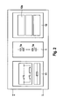
- FIG. 2 The basic functional structure of a battery system according to the prior art is in FIG. 2 shown.
- individual battery cells 1 a are connected in series in a battery and partially in parallel in addition.
- a so-called safety & fuse unit 11 Between the battery cells 1 a and the poles of the battery system is a so-called safety & fuse unit 11, which eg takes on and off the battery 1 to external systems and the protection of the battery system against excessive currents and voltages and provides security functions such as that unipolar disconnection of the battery cells 1 a from the battery system poles when opening the battery system housing.
- Another functional unit is the battery management 12, which, in addition to the battery condition detection 12a, also carries out the communication with other systems as well as the thermal management of the battery 1.
- function unit battery status detection 12a has the task to determine the current state of the battery 1 and to predict the future behavior of the battery 1, for example, a lifetime prediction and / or a range prediction.
- the prediction of future behavior is also called prediction.
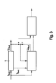
- the basic structure of a model-based battery condition detection is in FIG. 3 shown.
- the illustrated model-based battery state detection and prediction is based, for example, on an evaluation of the electrical quantities of battery current and voltage as well as the temperature of the battery.
- the battery state detection can be done for individual cells 1 a of a battery 1. This then takes place on the basis of the corresponding cell voltage, the cell current and the cell temperature.
- the battery condition detection can also be carried out for the entire battery 1.
- the total charge that can be taken from the battery cells 1a depends very much on the magnitude of the discharge current. Therefore, an accurate determination of the capacity of the battery cells 1 a, which refer to standard discharge conditions at room temperature and a discharge of eg 1C (discharge current in A corresponds nominal capacity of the battery in Ah), during normal operation of the battery 1 is very difficult, since any current waveforms can occur with different high discharge currents and charging phases occurring in between.
- FIG. 4 the functional principle of an arrangement for the so-called resistive balancing of battery cells is shown.
- the task of cell balancing is to ensure, in a series connection of several individual cells 1 a, that the cells 1 a all have almost the same state of charge or almost the same cell voltage. Due to the principle existing asymmetries of the battery cells 1a, for example, slightly different capacity, slightly different self-discharge, this would not be possible without additional measures during operation of the battery 1.
- the battery cells 1 a can be discharged by switching on an ohmic resistor R Bal_n arranged parallel to the cell, by connecting the resistor R Bal_n via the transistor T Bal _ N parallel to the cell n.
- inductive cell balancing in which a transhipment of energy stored in individual cells 1a, for example via an inductance.
- FIG. 5 A basic representation of inductive cell balancing is in FIG. 5 given.
- the model-based battery state detection and prediction presented above is based on an evaluation of the electrical quantities of battery current and voltage as well as the temperature of the battery. It is common to all prior art methods that the current, voltage and temperature profiles of the battery occurring during normal operation of the battery are used for determining the battery condition and for predicting the future behavior. In vehicles, the battery condition detection works automatically. US2006240291 discloses a method for determining characteristics of a battery according to the prior art.
- the method according to the invention with the features of patent claim 1 and the apparatus according to the invention with the features of patent claim 10 have the advantage that not only the operating processes occurring in the vehicle in normal operation can be used for the diagnosis of the characteristics of the battery, but a diagnosis not in normal operation or main operation, but eg when the vehicle is parked.
- a diagnosis not in normal operation or main operation but eg when the vehicle is parked.
- for the diagnosis of the properties of the battery larger changes in current and / or state of charge changes can be performed to perform the diagnosis.
- the inventive method and apparatus according to the invention include that the consumer is supplied in the main operation of the battery and is turned on, that is not turned off and is not in standby mode, in particular that in a vehicle as a consumer, the determination of the properties of the battery only started when the vehicle is parked.
- the method according to the invention additionally preferably comprises that the determination of the properties of the battery is only started when an operator of the consumer initiates the determination of the properties of the battery.
- the corresponding preferred development of the device according to the invention for this purpose comprises an operator interface, which is connected to the first control module, via which an operator can initiate the determination of the properties of the battery and which passes a corresponding control signal to the first control module.
- the method according to the invention further comprises, alternatively or additionally, that the determination of the properties of the battery is only started if a behavioral prediction via the user of the consumer indicates that the consumer does not have a probability above a specific limit within a predetermined following period of time is placed in the main operation.
- the corresponding preferred development of the device according to the invention for this purpose comprises a probability module which is connected to the first control module, which performs a behavioral prediction about the operator of the consumer to the effect that the consumer with a probability lying above a certain threshold in a predetermined subsequent period of time in the Main operation is set, and which passes a corresponding control signal to the first control module.
- the diagnosis of the battery is therefore preferably carried out by the driver when the vehicle is parked.
- This concept is based on the fact that the driver can specifically start the diagnosis of the battery via the human-machine interface of the vehicle if he intends to drive the vehicle for a defined minimum duration - e.g. at least two hours - turn off. Assuming that the vehicle is not restarted until after the minimum shutdown period, a diagnosis of the battery which has been expanded in comparison with the current state of the art can be carried out, in which essential parameters for battery state detection and prediction can be reliably determined with high accuracy. This represents a significant improvement compared to previous systems.
- the method according to the invention comprises, for determining the capacity of the battery, the following steps: transferring at least one cell of the battery into a first defined charging state, discharging or charging the at least one cell of the battery from the first defined charging state to a second defined state of charge, wherein during discharge or charging, a charge taken or supplied to the at least one cell is determined, and determining the capacity of the battery system based on the particular charge taken or supplied from the at least one cell.
- the corresponding preferred development of the device according to the invention comprises a second control module for transferring at least one cell of the battery into a first defined charge state and for discharging or charging the at least one cell of the battery from the first defined charge state to a second defined charge state, a charge measurement module. around one of the at least one cell taken or to determine supplied charge, and a capacity determination module for determining the capacity of the battery system based on the determined removed or supplied charge the at least one cell.
- the method according to the invention and the device according to the invention particularly preferably comprise that the charge removed or supplied during the discharging or charging of the at least one cell is based on the discharge current or charging current and / or on the at least one cell during discharging or charging Voltage and / or the rest voltage change of at least one cell is determined.
- the method according to the invention and the device according to the invention particularly preferably comprise that the first defined state is a fully charged state and the second defined state is a completely discharged state, or the first defined state is any state of the state Cell having at least 20% higher or lower charge than the second defined state.
- the method according to the invention and the device according to the invention comprise alternatively or additionally particularly preferably that the capacity is determined taking into account parameters of the discharging process or charging, in particular taking into account the discharge current or charging current and / or the ambient temperature during the Discharge and / or that the specific capacity of the battery system is converted to a standard discharge. In the correspondingly preferred development of the device according to the invention, this is done by the capacity determination module.
- the method according to the invention and the device according to the invention further, alternatively or additionally, particularly preferably, that the capacity of the battery system is determined on the basis of the determined removed or supplied charge of all cells, this being done over several operations of starting the Determining the characteristics of the battery can be done, or that the capacity of the battery system is determined based on the determined removed or supplied charge of a number of cells, which is lower than all cells of the battery system, preferably of these cells based on at least one previously performed battery state detection known is that they have a maximum and / or a minimum and / or an average capacity. In the corresponding preferred development of the device according to the invention, this is done by the second control module.
- the inventive method and the device according to the invention further alternatively or additionally particularly preferred that transferring at least one cell of the battery in a first defined state of charge and discharging or charging the at least one cell by means of a circuit for a Cell balancing, in particular by means of an inductive method occurs.
- the circuit for cell balancing is activated by the second control module.
- the charge-measuring module is preferably integrated in the circuit for the cell balancing.
- a method for determining the capacity of battery cells is preferably described, which can be used in battery systems with the use of inductive cell balancing without additional electronic circuitry.
- This method has the advantage compared with the current state of the art that the same operating sequence can always be brought about to determine the capacitance and thus a particularly robust and accurate determination becomes possible.
- the new method has the advantage that it is used in operating phases in which the battery is not integrated into the supply of a consumer, so in this regard does not give or receive power at their terminals, i. e.g. when the vehicle is turned off. This is not possible with the currently known methods for determining the capacity.
- the basic idea of the present invention is to carry out the diagnosis of certain battery properties during longer shutdown phases.
- the driver can be requested, for example via the human-machine interface (MMI) of the vehicle, to trigger such a battery diagnosis, if he will comply with a defined summonabstelldauer sure.
- MMI human-machine interface
- this is complied with, compared to the current state of the art significantly extended or more accurate diagnosis of certain battery properties can be performed without the Functionality of the battery system is adhered to after the minimum shutdown subsequently.
- longer test procedures for determining the current capacity of the battery or individual battery cells can be carried out.
- a short-term limitation of the functionality of the battery system may occur in the event of non-compliance with the minimum downtime, eg, this may be manifested by a reduced range in the immediately following travel in an electric vehicle.
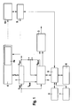
- a first control module 6 which initiates the battery diagnosis, eg via the observer 2 with battery model.
- the control module 6 is as it is in FIG. 1 is shown, connected to a query module 5, which indicates to the first control module 6, in which operating state, the consumer, here the vehicle, is, for example, whether it is in a main operation, ie driving works, including this, a short-term stop counts, or whether it is turned off.
- the first control module 6 is connected to an operator interface 7, which is integrated, for example, in the aforementioned human-machine interface, via which the operator of the consumer, here the driver of the vehicle, the determination of the properties of the battery can start.
- the first control module 6 is connected to a probability module 8, which preferably allows the determination of the properties of the battery only if a behavioral prediction made by the user of the consumer indicates that the consumer has a probability above a certain limit in one is not placed in the main operation for a predetermined subsequent period of time. This can be the case with vehicles, for example, when they are parked in a garage at night.
- FIG. 5 the basic principle for so-called inductive cell balancing is shown.
- Inductive cell balancing is used when the circuit concept for the alignment of the cell voltages or the state of charge of the cells transported on an inductive intermediate storage of the case electrical energy is based.
- Caching can - depending on the circuit concept - be carried out in chokes or transformers.
- the voltage U L across the inductive component can thereby - assuming ideal electronic switch with on-resistance to 0 and an ideal inductive component which has no ohmic internal resistance - simply from the one or more voltages of those cells from which the energy is taken, are determined.
- the equations (1) and (2) can thus be used to determine the charge taken from the cells.
- the non-ideal properties of the electronic switch used for cell balancing and of the inductive components cause, with suitable dimensioning of the components, only small errors in the determination of the charge taken from the cell (s).
- the charge transport which takes place when carrying out the cell balancing between the battery cells, can be determined.
- the circuit for carrying out the inductive cell balancing is preferably used to determine the capacity of the battery cells.
- the determination of the capacity takes place in phases in which the battery does not deliver or pick up power at its terminals.
- the cell 1 a To determine the capacity of a battery cell 1 a, the cell 1 a, starting from the state of charge, it has when parking the vehicle, first fully loaded. For this purpose, this cell 1a is supplied with the aid of the inductive cell balancing circuit 4, which is taken from other battery cells 1a. Due to the high efficiency that the circuit 4 has for inductive cell balancing with suitable dimensioning, only a small part of the transported energy is converted into heat. Starting from the fully charged state, the cell 1 a is then discharged to a defined state of charge (for example, to the state of charge 0%). The charge taken can be determined by the method described. The extracted energy is stored in other cells 1 a.
- a defined state of charge for example, to the state of charge 0%
- the cell 1 a is then recharged and it is carried out a cell balancing for symmetrizing the cell voltages and the charge states.
- the capacity of a battery cell 1 a can be determined very accurately.
- the height of the discharge current has an influence on the charge which can be taken from the battery cell 1 a during the discharge as a whole.
- the determined capacity thus refers to the parameters of the discharge process (eg discharge current, temperature).
- a great advantage of the method presented here is that again and again the same discharge currents can be used to determine the capacity and the normal operation (main operation) with its current curves not influenceable by the battery system has no negative influence.
- the capacity of the battery cell determined by the method according to the invention can be converted to a so-called standard discharge (for example at room temperature, discharge current 1C (discharge current corresponds to the nominal capacity value of the cell, for a cell with 4Ah capacity is the 1C current 4A)).
- discharge current 1C discharge current corresponds to the nominal capacity value of the cell, for a cell with 4Ah capacity is the 1C current 4A
- the cell 1 a is not brought into the fully charged state and then fully discharged, but it is only a certain voltage range of the cell (based on the so-called open circuit voltage OCV of the cell (open circuit voltage)) in the Go through the discharge and evaluate the charge taken.
- the state of charge of the cell should change at least in the order of 20%, so that a sufficiently accurate determination of the capacity is possible.
- FIG. 6 A diagram indicating the open circuit voltage of a cell via its state of charge is shown.
- an open circuit voltage change or quiescent voltage change of 0.2 V between about 3.85 V and 4.05 V in the ideal case corresponds to a discharged or supplied charge of 12 Ah, which in turn corresponds to a charge change of 20% for a 60 Ah cell.
- an open circuit voltage change or quiescent voltage change of 0.2 V between about 3.85 V and 4.05 V in the ideal case corresponds to a discharged or supplied charge of 12 Ah, which in turn corresponds to a charge change of 20% for a 60 Ah cell.
- the capacity of all individual cells 1a may not be determined completely during a shutdown phase in a battery 1 with a large number of battery cells 1a connected in series, but must extend over several shutdown phases. However, this is not a limitation for the method described. Often it is also quite sufficient to reduce the capacity of a few cells 1 a, e.g. the values of those cells in which, based on the performance of the battery state detection in normal operation, it is possible to assume that they have the largest or the smallest or an average capacity, are subjected to the described method in order to determine their capacity with high accuracy.
- the reduction of the capacity of the battery cells 1 a over the lifetime is one of the significant aging parameters of the battery cells 1 a.
- Accurate knowledge of the actual capacity of the cells 1a is essential for battery state detection and prediction.
- the capacity of the battery cells 1 a can only be determined in operating phases in which the state of charge of the cells during the "normal operation" (or main operation) changes appreciably (eg by at least 30%) and during this state of charge state is not extremely high Discharge currents occur. Therefore, the determination of the capacity of the battery cells with the described method can be performed much more robustly and accurately compared to the prior art.
- a second control module 9 which controls the circuit 4 for cell balancing, which includes the charge measurement module 4 a, as well as a capacitance determination module 10, which is connected to the charge measurement module 4 a, suitably.
- the second control module 9 is connected to the first Control module 6 connected so that it can initiate the respective start of a battery diagnosis.
Description
Die vorliegende Erfindung betrifft ein Verfahren und eine Vorrichtung zur Ermittlung von Eigenschaften einer Batterie, insbesondere einer Traktionsbatterie, gemäß den Oberbegriffen der Patentansprüche 1 und 10.The present invention relates to a method and a device for determining properties of a battery, in particular a traction battery, according to the preambles of
Es zeichnet sich ab, dass in Zukunft sowohl bei stationären Anwendungen (z.B. bei Windkraftanlagen) als auch in Fahrzeugen (z.B. in Hybrid- und Elektrofahrzeugen) vermehrt neue Batteriesysteme zum Einsatz kommen werden. Die Begriffe Batterie und Batteriesystem werden in der vorliegenden Beschreibung dem üblichen Sprachgebrauch angepasst für Akkumulator bzw. Akkumulatorsystem verwendet.It is becoming apparent that in the future, more and more new battery systems will be used both in stationary applications (for example in wind turbines) and in vehicles (for example in hybrid and electric vehicles). The terms battery and battery system are used in the present description, the usual parlance used for accumulator or Akkumulatorsystem.
Der prinzipielle funktionale Aufbau eines Batteriesystems gemäß dem Stand der Technik ist in
Die in
In
Die zuvor dargestellte modellbasierte Batteriezustandserkennung und -prädiktion basiert auf einer Auswertung der elektrischen Größen Batteriestrom und -spannung sowie der Temperatur der Batterie. Allen Verfahren gemäß Stand der Technik ist dabei gemein, dass die im normalen Betrieb der Batterie auftretenden Strom-, Spannungs- und Temperaturverläufe der Batterie für die Ermittlung des Batteriezustands sowie für die Prädiktion des künftigen Verhaltens herangezogen werden. In Fahrzeugen arbeitet die Batteriezustandserkennung automatische.
Aufgabe der vorliegenden Erfindung ist es, ein neues Konzept für die Durchführung der Batteriezustandserkennung (Diagnose der Batterie) vorzustellen, mit dem die Batteriezustandserkennung und -prädiktion gegenüber dem heutigen Stand der Technik robuster und genauer realisiert werden kann.It is an object of the present invention to provide a novel concept for performing battery state detection (battery diagnostics) that can more robustly and accurately realize battery state detection and prediction over the current state of the art.
Das erfindungsgemäße Verfahren mit den Merkmalen des Patentanspruchs 1 und die erfindungsgemäße Vorrichtung mit den Merkmalen des Patentanspruchs 10 weisen demgegenüber den Vorteil auf, dass nicht nur die im Normalbetrieb im Fahrzeug auftretenden Betriebsabläufe für die Diagnose der Eigenschaften der Batterie herangezogen werden bzw. herangezogen werden können, sondern eine Diagnose nicht im Normalbetrieb oder Hauptbetrieb, sondern z.B. bei abgestelltem Fahrzeug erfolgt. Damit können erfindungsgemäß zur Diagnose der Eigenschaften der Batterie größere Stromänderungen und/oder Ladezustandsänderungen durchgeführt werden, um den Diagnose durchzuführen.The method according to the invention with the features of patent claim 1 and the apparatus according to the invention with the features of
Die Unteransprüche zeigen bevorzugte Weiterbildungen der Erfindung.The dependent claims show preferred developments of the invention.
Das erfindungsgemäße Verfahren und die erfindungsgemäße Vorrichtung umfassen, dass der Verbraucher in dem Hauptbetrieb von der Batterie versorgt wird und angeschaltet ist, also nicht ausgeschaltet ist und sich nicht im Standby-Betrieb befindet, insbesondere dass bei einem Fahrzeug als Verbraucher die Ermittlung der Eigenschaften der Batterie nur dann gestartet wird, wenn das Fahrzeug abgestellt ist.The inventive method and apparatus according to the invention include that the consumer is supplied in the main operation of the battery and is turned on, that is not turned off and is not in standby mode, in particular that in a vehicle as a consumer, the determination of the properties of the battery only started when the vehicle is parked.
Das erfindungsgemäße Verfahren umfasst zusätlich bevorzugt, dass die Ermittlung der Eigenschaften der Batterie nur dann gestartet wird, wenn ein Bediener des Verbrauchers die Ermittlung der Eigenschaften der Batterie initiiert. Die korrespondierende bevorzugte Weiterbildung der erfindungsgemäßen Vorrichtung umfasst hierfür eine Bedienerschnittstelle, die mit dem ersten Steuermodul verbunden ist, über die ein Bediener die Ermittlung der Eigenschaften der Batterie initiieren kann und die ein entsprechendes Steuersignal an das erste Steuermodul leitet.The method according to the invention additionally preferably comprises that the determination of the properties of the battery is only started when an operator of the consumer initiates the determination of the properties of the battery. The corresponding preferred development of the device according to the invention for this purpose comprises an operator interface, which is connected to the first control module, via which an operator can initiate the determination of the properties of the battery and which passes a corresponding control signal to the first control module.
Das erfindungsgemäße Verfahren umfasst weiter alternativ oder zusätzlich bevorzugt, dass die Ermittlung der Eigenschaften der Batterie nur dann gestartet wird, wenn eine Verhaltensvorhersage über den Bediener des Verbrauchers anzeigt, dass der Verbraucher mit einer über einem bestimmten Grenzwert liegenden Wahrscheinlichkeit in einer vorbestimmten folgenden Zeitspanne nicht in den Hauptbetrieb versetzt wird. Die korrespondierende bevorzugte Weiterbildung der erfindungsgemäßen Vorrichtung umfasst hierfür ein Wahrscheinlichkeitsmodul, das mit dem ersten Steuermodul verbunden ist, das eine Verhaltensvorhersage über den Bediener des Verbrauchers dahingehend durchführt, ob der Verbraucher mit einer über einem bestimmten Grenzwert liegenden Wahrscheinlichkeit in einer vorbestimmten folgenden Zeitspanne nicht in den Hauptbetrieb versetzt wird, und das ein entsprechendes Steuersignal an das erste Steuermodul leitet.The method according to the invention further comprises, alternatively or additionally, that the determination of the properties of the battery is only started if a behavioral prediction via the user of the consumer indicates that the consumer does not have a probability above a specific limit within a predetermined following period of time is placed in the main operation. The corresponding preferred development of the device according to the invention for this purpose comprises a probability module which is connected to the first control module, which performs a behavioral prediction about the operator of the consumer to the effect that the consumer with a probability lying above a certain threshold in a predetermined subsequent period of time in the Main operation is set, and which passes a corresponding control signal to the first control module.
Erfindungsgemäß wird die Diagnose der Batterie also bevorzugt durch den Fahrer ausgelöst bei abgestelltem Fahrzeug durchgeführt. Dieses Konzept basiert darauf, dass der Fahrer die Diagnose der Batterie gezielt über das Mensch-Maschine-Interface des Fahrzeugs starten kann, wenn er beabsichtigt, das Fahrzeug für eine definierte Mindestdauer - z.B. mindestens zwei Stunden - abzustellen. Unter Annahme, dass das Fahrzeug erst nach der Mindestabstelldauer wieder gestartet wird, kann eine gegenüber dem heutigen Stand der Technik erweiterte Diagnose der Batterie durchgeführt werden, bei der wesentliche Parameter für die Batteriezustandserkennung und -prädiktion zuverlässig mit hoher Genauigkeit ermittelt werden können. Dies stellt eine wesentliche Verbesserung im Vergleich zu bisherigen Systemen dar.According to the invention, the diagnosis of the battery is therefore preferably carried out by the driver when the vehicle is parked. This concept is based on the fact that the driver can specifically start the diagnosis of the battery via the human-machine interface of the vehicle if he intends to drive the vehicle for a defined minimum duration - e.g. at least two hours - turn off. Assuming that the vehicle is not restarted until after the minimum shutdown period, a diagnosis of the battery which has been expanded in comparison with the current state of the art can be carried out, in which essential parameters for battery state detection and prediction can be reliably determined with high accuracy. This represents a significant improvement compared to previous systems.
Das erfindungsgemäße Verfahren umfasst noch weiter alternativ oder zusätzlich bevorzugt, dass zur Ermittelung der Kapazität der Batterie die folgenden Schritte ausgeführt werden: Überführen wenigstens einer Zelle der Batterie in einen ersten definierten Ladezustand, Entladen oder Laden der wenigstens einen Zelle der Batterie von dem ersten definierten Ladezustand bis zu einem zweiten definierten Ladezustand, wobei während des Entladens oder Ladens eine der wenigstens einen Zelle entnommene oder zugeführte Ladung bestimmt wird, und Ermitteln der Kapazität des Batteriesystems anhand der bestimmten entnommenen oder zugeführten Ladung der wenigstens einen Zelle. Die korrespondierende bevorzugte Weiterbildung der erfindungsgemäßen Vorrichtung umfasst hierfür ein zweites Steuermodul zum Überführen wenigstens einer Zelle der Batterie in einen ersten definierten Ladezustand und zum Entladen oder Laden der wenigstens einen Zelle der Batterie von dem ersten definierten Ladezustand bis zu einem zweiten definierten Ladezustand, ein Ladungsmessungsmodul, um eine der wenigstens einen Zelle entnommene oder zugeführte Ladung zu bestimmen, und ein Kapazitätsbestimmungsmodul zum Ermitteln der Kapazität des Batteriesystems anhand der bestimmten entnommenen oder zugeführten Ladung der wenigstens einen Zelle.Still further alternatively or additionally, the method according to the invention comprises, for determining the capacity of the battery, the following steps: transferring at least one cell of the battery into a first defined charging state, discharging or charging the at least one cell of the battery from the first defined charging state to a second defined state of charge, wherein during discharge or charging, a charge taken or supplied to the at least one cell is determined, and determining the capacity of the battery system based on the particular charge taken or supplied from the at least one cell. The corresponding preferred development of the device according to the invention comprises a second control module for transferring at least one cell of the battery into a first defined charge state and for discharging or charging the at least one cell of the battery from the first defined charge state to a second defined charge state, a charge measurement module. around one of the at least one cell taken or to determine supplied charge, and a capacity determination module for determining the capacity of the battery system based on the determined removed or supplied charge the at least one cell.
In diesem Fall umfassen das erfindungsgemäße Verfahren und die erfindungsgemäße Vorrichtung besonders bevorzugt, dass die der während des Entladens oder Ladens der wenigstens einen Zelle entnommene oder zugeführte Ladung anhand des Entladestroms oder Ladestroms und/oder einer während des Entladens oder Ladens an der wenigstens einen Zelle anliegenden Spannung und/oder der Ruhespannungsänderung der wenigstens einen Zelle bestimmt wird.In this case, the method according to the invention and the device according to the invention particularly preferably comprise that the charge removed or supplied during the discharging or charging of the at least one cell is based on the discharge current or charging current and / or on the at least one cell during discharging or charging Voltage and / or the rest voltage change of at least one cell is determined.
Bei der obigen Ermittlung der Kapazität der Batterie umfassen das erfindungsgemäße Verfahren und die erfindungsgemäße Vorrichtung besonders bevorzugt, dass der erste definierte Zustand ein voll geladener Zustand ist und der zweite definierte Zustand ein vollständig entladener Zustand ist, oder dass der erste definierte Zustand ein beliebiger Zustand der Zelle ist, der eine um wenigstens 20% höhere oder niedrigere Ladung als der zweite definierte Zustand aufweist.In the above determination of the capacity of the battery, the method according to the invention and the device according to the invention particularly preferably comprise that the first defined state is a fully charged state and the second defined state is a completely discharged state, or the first defined state is any state of the state Cell having at least 20% higher or lower charge than the second defined state.
Bei der obigen Ermittlung der Kapazität der Batterie umfassen das erfindungsgemäße Verfahren und die erfindungsgemäße Vorrichtung alternativ oder zusätzlich besonders bevorzugt, dass die Kapazität unter Berücksichtigung von Parametern des Entladevorgangs oder Ladevorgangs bestimmt wird, insbesondere unter Berücksichtigung des Entladestroms oder Ladestroms und/oder der Umgebungstemperatur während der Entladung und/oder dass die bestimmte Kapazität des Batteriesystems auf eine Normentladung umgerechnet wird. In der korrespondierenden bevorzugten Weiterbildung der erfindungsgemäßen Vorrichtung erfolgt dies durch das Kapazitätsbestimmungsmodul.In the above determination of the capacity of the battery, the method according to the invention and the device according to the invention comprise alternatively or additionally particularly preferably that the capacity is determined taking into account parameters of the discharging process or charging, in particular taking into account the discharge current or charging current and / or the ambient temperature during the Discharge and / or that the specific capacity of the battery system is converted to a standard discharge. In the correspondingly preferred development of the device according to the invention, this is done by the capacity determination module.
Bei der obigen Ermittlung der Kapazität der Batterie umfassen das erfindungsgemäße Verfahren und die erfindungsgemäße Vorrichtung weiter alternativ oder zusätzlich besonders bevorzugt, dass die Kapazität des Batteriesystems anhand der ermittelten entnommenen oder zugeführten Ladung aller Zellen ermittelt wird, wobei dies über mehrere Vorgänge des Startens der Ermittlung der Eigenschaften der Batterie erfolgen kann, oder dass die Kapazität des Batteriesystems anhand der ermittelten entnommenen oder zugeführten Ladung einer Anzahl von Zellen ermittelt wird, die geringer ist, als alle Zellen des Batteriesystems, wobei vorzugsweise von diesen Zellen anhand wenigstens einer zuvor durchgeführten Batteriezustandserkennung bekannt ist, dass diese eine größte und/oder eine kleinste und/oder eine durchschnittliche Kapazität aufweisen. In der korrespondierenden bevorzugten Weiterbildung der erfindungsgemäßen Vorrichtung erfolgt dies durch das zweite Steuermodul.In the above determination of the capacity of the battery, the method according to the invention and the device according to the invention further, alternatively or additionally, particularly preferably, that the capacity of the battery system is determined on the basis of the determined removed or supplied charge of all cells, this being done over several operations of starting the Determining the characteristics of the battery can be done, or that the capacity of the battery system is determined based on the determined removed or supplied charge of a number of cells, which is lower than all cells of the battery system, preferably of these cells based on at least one previously performed battery state detection known is that they have a maximum and / or a minimum and / or an average capacity. In the corresponding preferred development of the device according to the invention, this is done by the second control module.
Bei der obigen Ermittlung der Kapazität der Batterie umfassen das erfindungsgemäße Verfahren und die erfindungsgemäße Vorrichtung weiter alternativ oder zusätzlich besonders bevorzugt, dass das Überführen wenigstens einer Zelle der Batterie in einen ersten definierten Ladezustand und das Entladen oder Laden der wenigstens einen Zelle mittels einer Schaltung für ein Zellbalancing, insbesondere mittels eines induktiven Verfahrens, erfolgt. In der korrespondierenden bevorzugten Weiterbildung der erfindungsgemäßen Vorrichtung erfolgt eine Ansteuerung der Schaltung für das Zellbalancing durch das zweite Steuermodul. Hier ist weiter bevorzugt das Ladungsmessungsmodul in der Schaltung für das Zellbalancing integriert.In the above determination of the capacity of the battery, the inventive method and the device according to the invention further alternatively or additionally particularly preferred that transferring at least one cell of the battery in a first defined state of charge and discharging or charging the at least one cell by means of a circuit for a Cell balancing, in particular by means of an inductive method occurs. In the correspondingly preferred development of the device according to the invention, the circuit for cell balancing is activated by the second control module. Here, furthermore, the charge-measuring module is preferably integrated in the circuit for the cell balancing.
Erfindungsgemäß wird also bevorzugt ein Verfahren zur Ermittlung der Kapazität von Batteriezellen beschrieben, das bei Batteriesystemen mit Einsatz von induktivem Zellbalancing ohne zusätzlichen elektronischen Schaltungsaufwand zum Einsatz kommen kann. Dieses Verfahren hat gegenüber dem heutigen Stand der Technik den Vorteil, dass zur Ermittlung der Kapazität immer wieder der gleiche Betriebablauf herbeigeführt werden kann und dadurch eine besonders robuste und genaue Bestimmung möglich wird. Darüber hinaus hat das neue Verfahren den Vorteil, dass es in Betriebsphasen eingesetzt wird, in denen die Batterie nicht in die Versorgung eines Verbrauchers eingebunden ist, also diesbezüglich an ihren Klemmen keine Leistung abgibt oder aufnimmt, d.h. z.B. bei abgestelltem Fahrzeug. Dies ist bei den aktuell bekannten Verfahren zur Kapazitätsbestimmung nicht möglich.Thus, according to the invention, a method for determining the capacity of battery cells is preferably described, which can be used in battery systems with the use of inductive cell balancing without additional electronic circuitry. This method has the advantage compared with the current state of the art that the same operating sequence can always be brought about to determine the capacitance and thus a particularly robust and accurate determination becomes possible. In addition, the new method has the advantage that it is used in operating phases in which the battery is not integrated into the supply of a consumer, so in this regard does not give or receive power at their terminals, i. e.g. when the vehicle is turned off. This is not possible with the currently known methods for determining the capacity.
Nachfolgend wird ein Ausführungsbeispiel der Erfindung unter Bezugnahme auf die begleitende Zeichnung im Detail beschrieben. In der Zeichnung zeigen:
- Figur 1
- ein Prinzipschaltbild einer ersten bevorzugten Ausführungsform einer erfindungsgemäßen Vorrichtung zur Ermittlung von Eigenschaften einer Batterie,
Figur 2- einen funktionalen Aufbau eines Batteriesystems gemäß dem Stand der Technik,
Figur 3- ein Prinzipschaltbild einer modellbasierten Batteriezustandserkennung und -prädiktion nach dem Stand der Technik,
Figur 4- ein Prinzipschaltbild einer Anordnung für ein resistives Zellbalancing der Batteriezellen nach dem Stand der Technik,
Figur 5- ein Prinzipschaltbild eines induktiven Balancing der Batteriezellen nach dem Stand der Technik, und
Figur 6- ein Diagramm der Ruhespannung einer Batteriezelle über deren Ladezustand.
- FIG. 1
- FIG. 3 is a block diagram of a first preferred embodiment of a device according to the invention for determining characteristics of a battery. FIG.
- FIG. 2
- a functional structure of a battery system according to the prior art,
- FIG. 3
- FIG. 2 is a block diagram of a prior art model-based battery state detection and prediction; FIG.
- FIG. 4
- FIG. 1 shows a block diagram of an arrangement for a resistive cell balancing of the battery cells according to the prior art, FIG.
- FIG. 5
- a schematic diagram of an inductive balancing of the battery cells according to the prior art, and
- FIG. 6
- a diagram of the rest voltage of a battery cell on the state of charge.
Nachfolgend werden unter Bezugnahme auf die Figuren bevorzugte Ausführungsformen der Erfindung im Detail beschrieben.Hereinafter, with reference to the figures, preferred embodiments of the invention will be described in detail.
Grundgedanke der vorliegenden Erfindung ist, die Diagnose bestimmter Batterieeigenschaften während längeren Abstellphasen durchzuführen. Dazu kann der Fahrer z.B. über das Mensch-Maschine-Interface (MMI) des Fahrzeugs aufgefordert werden, eine solche Batteriediagnose dann auszulösen, wenn er eine definierte Mindestabstelldauer sicher einhalten wird. Unter der Annahme, dass diese Mindestabstelldauer eingehalten wird, kann eine gegenüber dem heutigen Stand der Technik deutlich erweiterte bzw. genauere Diagnose bestimmter Batterieeigenschaften durchgeführt werden, ohne dass die Funktionalität des Batteriesystems bei Einhaltung der Mindestabstelldauer anschließend beeinträchtigt wird. So können z.B. länger dauernde Testprozeduren zur Bestimmung der aktuellen Kapazität der Batterie bzw. einzelner Batteriezellen durchgeführt werden. Je nach Ausführung der Diagnose kann es bei Nichteinhaltung der Mindestabstelldauer ggf. kurzfristig zu einer Einschränkung der Funktionalität des Batteriesystems kommen, z.B. kann dies sich bei der unmittelbar anschließenden Fahrt in einem Elektrofahrzeug durch eine verringerte Reichweite äußern.The basic idea of the present invention is to carry out the diagnosis of certain battery properties during longer shutdown phases. For this purpose, the driver can be requested, for example via the human-machine interface (MMI) of the vehicle, to trigger such a battery diagnosis, if he will comply with a defined Mindestabstelldauer sure. Assuming that this Mindestabstelldauer is complied with, compared to the current state of the art significantly extended or more accurate diagnosis of certain battery properties can be performed without the Functionality of the battery system is adhered to after the minimum shutdown subsequently. For example, longer test procedures for determining the current capacity of the battery or individual battery cells can be carried out. Depending on the design of the diagnosis, a short-term limitation of the functionality of the battery system may occur in the event of non-compliance with the minimum downtime, eg, this may be manifested by a reduced range in the immediately following travel in an electric vehicle.
Hierfür ist erfindungsgemäß ein erstes Steuermodul 6 vorgesehen, welches die Batteriediagnose, z.B. über den Beobachter 2 mit Batteriemodell initiiert. Das Steuermodul 6 ist, wie es in
In
Beim induktiven Zellbalancing wird in einem ersten Schritt Energie aus einer oder mehrer Zellen entnommen und in dem induktiven Speicher zwischengespeichert. In einem zweiten Schritt wird die zwischengespeicherte Energie in eine oder mehrere Batteriezellen zurückgespeichert. Als Beispiele seien genannt:
- Energieentnahme aus einer Zelle und Zurückspeicherung in eine oder mehrere Zellen, wobei in die Zelle, aus der Energie entnommen wurde, nicht zurückgespeichert wird;
- Energieentnahme aus einer Zelle und Zurückspeicherung in eine oder mehrere Zellen, wobei ein Teil der Energie in die Zelle, aus der Energie entnommen wurde, zurückgespeichert wird;
- Energieentnahme aus mehreren Zelle und Zurückspeicherung in eine oder mehrere Zellen, wobei in die Zellen, aus denen Energie entnommen wurde, nicht zurückgespeichert wird;
- Energieentnahme aus mehreren Zellen und Zurückspeicherung in eine oder mehrere Zellen, wobei ein Teil der Energie in die Zellen, aus denen Energie entnommen wurde, zurückgespeichert wird.
- Extracting energy from a cell and restoring it into one or more cells, without restoring to the cell from which energy was drawn;
- Extracting energy from a cell and restoring it to one or more cells, wherein a portion of the energy is restored to the cell from which energy was extracted;
- Extracting energy from a plurality of cells and restoring them into one or more cells, without restoring into the cells from which energy was drawn;
- Extracting energy from multiple cells and restoring it to one or more cells, with some of the energy being restored to the cells from which energy was drawn.
Die Ladung, die im ersten Schritt aus der oder den Zellen entnommen wurde, kann über die Spannungszeitfläche bei bekannter Induktivität des zur Zwischenspeicherung der Energie eingesetzten Speichers wie folgt berechnet werden:
- Der zeitliche Verlauf des Stroms in dem induktiven Bauelement ergibt sich zu

- The time course of the current in the inductive component results to
Der Maximalstrom an Ende des ersten Schritt und sei mit ILmax bezeichnet.
- Die im ersten Schritt entnommene Ladung kann wie folgt berechnet werden:
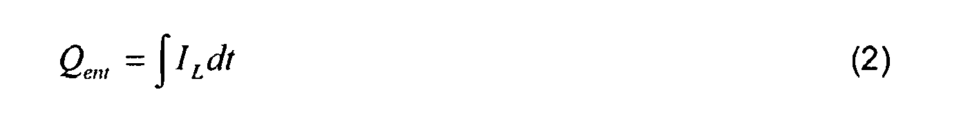
- The charge taken in the first step can be calculated as follows:
Die Spannung UL an dem induktiven Bauelement kann dabei - unter Annahme idealer elektronischer Schalter mit Durchlasswiderstand gegen 0 sowie eines idealen induktiven Bauelements welches keinen ohmschen Innenwiderstand aufweist - einfach aus der oder den Spannungen jener Zellen, aus den die Energie entnommen wird, ermittelt werden. Über die Gleichungen (1) und (2) kann somit den Zellen entnommen Ladung bestimmt werden. Die nichtidealen Eigenschaften der für das Zellbalancing eingesetzten elektronischen Schalter sowie der induktiven Bauelemente bewirken bei geeigneter Dimensionierung der Bauelemente nur geringe Fehler bei der Ermittlung der Ladung, die der oder den Zellen entnommen wird.The voltage U L across the inductive component can thereby - assuming ideal electronic switch with on-resistance to 0 and an ideal inductive component which has no ohmic internal resistance - simply from the one or more voltages of those cells from which the energy is taken, are determined. The equations (1) and (2) can thus be used to determine the charge taken from the cells. The non-ideal properties of the electronic switch used for cell balancing and of the inductive components cause, with suitable dimensioning of the components, only small errors in the determination of the charge taken from the cell (s).
In äquivalenter Form kann im 2. Schritt das Zurückspeisen der zwischengespeicherten Energie in die Zelle(n) berechnet werden:
- Der zeitliche Verlauf des Stroms in dem induktiven Bauelement ergibt sich zu

- The time course of the current in the inductive component results to
Nachdem der Strom IL den Wert 0 angenommen hat, gilt: ![]()
- Die im zweiten Schritt zurückgespeiste Ladung kann wie folgt berechnet werden:

- The charge fed back in the second step can be calculated as follows:
Somit kann der Ladungstransport, welcher bei der Durchführung des Zellbalancing zwischen den Batteriezellen erfolgt, bestimmt werden.Thus, the charge transport, which takes place when carrying out the cell balancing between the battery cells, can be determined.
Erfindungsgemäß wird bevorzugt die Schaltung zur Durchführung des induktiven Zellbalancing dazu genutzt, die Kapazität der Batteriezellen zu ermitteln. Die Bestimmung der Kapazität erfolgt dabei in Phasen, in denen die Batterie an ihren Klemmen keine Leistung abgibt oder aufnimmt.According to the invention, the circuit for carrying out the inductive cell balancing is preferably used to determine the capacity of the battery cells. The determination of the capacity takes place in phases in which the battery does not deliver or pick up power at its terminals.
Zur Ermittlung der Kapazität einer Batteriezelle 1 a kann die Zelle 1 a ausgehend von dem Ladezustand, den sie beim Abstellen des Fahrzeugs aufweist, zunächst voll geladen werden. Dazu wird dieser Zelle 1a mit Hilfe der Schaltung 4 für das induktive Zellbalancing Ladung zugeführt, die aus anderen Batteriezellen 1a entnommen wird. Aufgrund des hohen Wirkungsgrades, den die Schaltung 4 für das induktive Zellbalancing bei geeigneter Dimensionierung aufweist, wird dabei nur ein geringer Teil der transportierten Energie in Wärme umgewandelt. Ausgehend von dem vollgeladenen Zustand wird die Zelle 1 a dann bis zu einem definierten Ladezustand (z.B. bis auf den Ladezustand 0%) entladen. Die dabei entnommene Ladung kann mit dem beschriebenen Verfahren ermittelt werden. Die entnommene Energie wird in anderen Zellen 1 a gespeichert. Die Zelle 1 a wird anschließend wieder geladen und es wird ein Zellbalancing zur Symmetrierung der Zellspannungen bzw. der Ladezustände durchgeführt. Auf diese Weise kann die Kapazität einer Batteriezelle 1 a sehr genau ermittelt werden. Die Höhe des Entladestroms hat Einfluss auf die Ladung, die der Batteriezelle 1 a während der Entladung insgesamt entnommen werden kann. Die ermittelte Kapazität bezieht sich somit auf die Parameter des Entladevorgangs (z.B. Entladestrom, Temperatur). Ein großer Vorteil des hier vorgestellten Verfahrens ist, dass immer wieder die gleichen Entladeströme zur Ermittlung der Kapazität herangezogen werden können und der Normalbetrieb (Hauptbetrieb) mit seinen von dem Batteriesystem nicht beeinflussbaren Stromverläufen keinen negativen Einfluss nimmt.To determine the capacity of a
Die mit dem erfindungsgemäßen Verfahren ermittelte Kapazität der Batteriezelle kann auf eine sogenannte Normentladung (erfolgt z.B. bei Raumtemperatur, Entladestrom 1C (Entladestrom entspricht dem Nennkapazitätswert der Zelle, bei einer Zelle mit 4Ah Kapazität beträgt der 1C-Strom 4A)) umgerechnet werden.The capacity of the battery cell determined by the method according to the invention can be converted to a so-called standard discharge (for example at room temperature, discharge current 1C (discharge current corresponds to the nominal capacity value of the cell, for a cell with 4Ah capacity is the 1C current 4A)).
In einer abgewandelten Form des bevorzugten erfindungsgemäßen Verfahrens wird die Zelle 1 a nicht in den vollgeladenen Zustand gebracht und anschließend voll entladen, sondern es wird ein nur bestimmter Spannungsbereich der Zelle (bezogen auf die sogenannte Open Circuit Voltage OCV der Zelle (Leerlaufspannung)) bei der Entladung durchfahren und die dabei entnommene Ladung ausgewertet. Der Ladezustand der Zelle sollte sich dabei mindestens in der Größenordnung von 20% ändern, damit eine ausreichend genaue Bestimmung der Kapazität möglich wird. Ein Diagramm, das die Leerlaufspannung einer Zelle über deren Ladezustand angibt, ist in
Die Kapazität aller Einzelzellen 1a kann bei einer Batterie 1 mit sehr vielen in Reihe geschalteten Batteriezellen 1a ggf. nicht komplett während einer Abstellphase ermittelt werden, sondern muss sich über mehrere Abstellphasen erstrecken. Dies stellt für das beschriebene Verfahren jedoch keine Einschränkung dar. Häufig ist es auch völlig ausreichend, die Kapazität einiger weniger Zellen 1 a, z.B. die Werte jener Zellen, bei denen man aufgrund der Durchführung der Batteriezustandserkennung im Normalbetrieb davon ausgehen kann, dass Sie die größte bzw. die kleinste oder eine durchschnittliche Kapazität aufweisen, dem beschriebenen Verfahren zu unterziehen, um deren Kapazität mit hoher Genauigkeit zu ermitteln.The capacity of all
Die Verringerung der Kapazität der Batteriezellen 1 a über der Lebensdauer ist einer der wesentlichen Alterungsparameter der Batteriezellen 1 a. Eine genaue Kenntnis der aktuellen Kapazität der Zellen 1 a ist für die Batteriezustandserkennung und -prädiktion von wesentlicher Bedeutung. Bei den bisher bekannten Verfahren kann die Kapazität der Batteriezellen 1 a nur in Betriebsphasen ermittelt werden, bei denen der Ladzustand der Zellen sich während des "Normalbetriebs" (oder Hauptbetriebs) nennenswert ändert (z.B. um mindestens 30%) und während dieser Ladezustandsänderung keine extrem hohen Entladeströme auftreten. Daher kann die Ermittlung der Kapazität der Batteriezellen mit dem beschriebenen Verfahren im Vergleich zum Stand der Technik wesentlich robuster und genauer durchgeführt werden.The reduction of the capacity of the
Für diese erfindungsgemäß bevorzugt durchgeführte Ermittlung der Kapazität der Batteriezellen ist ein zweites Steuermodul 9 vorgesehen, welches die Schaltung 4 für das Zellbalancing, die das Ladungsmessungsmodul 4a umfasst, sowie ein Kapazitätsbestimmungsmodul 10, das mit dem Ladungsmessungsmodul 4a verbunden ist, geeignet ansteuert. Das zweite Steuermodul 9 ist mit dem ersten Steuermodul 6 verbunden, damit dieses den jeweiligen Start einer Batteriediagnose initiieren kann.For this inventively preferred determination of the capacity of the battery cells, a second control module 9 is provided, which controls the
Neben der obigen schriftlichen Offenbarung wird hier ausdrücklich auf die Offenbarung in den Figuren verwiesen.In addition to the above written disclosure, reference is expressly made to the disclosure in the figures.
Claims (19)
- Method for establishing properties of a battery (1), in particular of a traction battery, in particular a battery state such as a capacity and/or a state of charge and/or a remaining service life of the battery (1), in particular by means of model-based state identification (2, 3), comprising the steps of:- checking an operating state of a load which is supplied with power by the battery (1), and- starting the process of establishing the properties of the battery (1) only when the operating state of the supplied load indicates that said load is not operating in a principal mode,characterized in that
the load is supplied with power by the battery (1) in the principal mode and is switched on, that is to say is not switched off, and is not in the standby mode, in particular in that, in the case of a vehicle as the load, the process of establishing the properties of the battery (1) is started only when the vehicle (1) is turned off. - Method according to Claim 1, characterized in that the process of establishing the properties of the battery (1) is started only when an operator of the load initiates the process of establishing the properties of the battery (1).
- Method according to either of the preceding claims, characterized in that the process of establishing the properties of the battery (1) is started only when a prediction of behaviour by the operator of the load indicates with a level of probability which is above a specific limit value that the load will not be moved to the principal mode within a predetermined following time period.
- Method according to one of the preceding claims, with the following steps being executed in order to establish the capacity of the battery (1):- changing over at least one cell (1a) of the battery (1) to a first defined state of charge,- discharging or charging the at least one cell (1a) of the battery (1) from the first defined state of charge to a second defined state of charge, with a charge which is drawn from or supplied to the at least one cell (1a) being determined during the discharging or charging process, and- establishing the capacity of the battery (1) on the basis of the determined charge which is drawn from or supplied to the at least one cell (1a).
- Method according to Claim 4, characterized in that the charge which is drawn from or supplied to the at least one cell during the discharging or charging process is determined on the basis of the discharge current or charge current and/or a voltage which is applied to the at least one cell during the discharging or charging process and/or the change in the open-circuit voltage of the at least one cell.
- Method according to Claim 4 or 5, characterized in that- the first defined state is a fully charged state and the second defined state is a fully discharged state, or in that- the first defined state is any desired state of the cell (1a) which has a charge which is at least 20% higher or lower than the second defined state.
- Method according to one of Claims 4 to 6, characterized in that- the capacity is determined taking into account parameters of the discharging process or charging process, in particular taking into account the discharge current or charge current and/or the ambient temperature during the discharging or charging process and/or in that- the determined capacity of the battery (1) is converted to a standard discharge.
- Method according to one of Claims 4 to 7, characterized in that- the capacity of the battery (1) is established on the basis of the established charge of all the cells (1a), it being possible for this to be carried out over several processes for starting the process of establishing the properties of the battery (1), or in that- the capacity of the battery (1) is established on the basis of the established charge of a number of cells (1a) which is lower than all the cells (1a) of the battery (1), with it preferably being known of these cells (1a) on the basis of at least one previously carried out battery state identification process that the said cells have a maximum and/or a minimum and/or an average capacity.
- Method according to one of Claims 4 to 8, characterized in that- at least one cell (1a) of the battery (1) is changed over to a first defined state of charge and the at least one cell (1a) is discharged or charged by means of a circuit (4) for cell balancing, in particular by means of an inductive process.
- Apparatus for establishing properties of a battery (1), in particular of a traction battery, in particular a battery state such as a capacity and/or a state of charge and/or a remaining service life of the battery (1), preferably using an observer (2) and a battery model for model-based state identification (3), comprising:- a checking module (5) for checking an operating state of a load which is supplied with power by the battery (1), and- a first control module (6) for starting the process of establishing the properties of the battery (1) only when the operating state of the load which is supplied with power indicates that the said load is not operating in a principal mode,characterized in that the load is supplied with power by the battery (1) in the principal mode and is switched on, that is to say is not switched off, and is not in the standby mode, in particular in that, in the case of a vehicle as the load, the process of establishing the properties of the battery (1) is started only when the vehicle is turned off.
- Apparatus according to Claim 10, characterized by an operator interface (7) which is connected to the first control module (6) and by means of which an operator can initiate the process of establishing the properties of the battery (1) and which conducts a corresponding control signal to the first control module (6).
- Apparatus according to either of Claims 10 and 11, characterized by a probability module (8) which is connected to the first control module (6), which carries out a behaviour prediction by the operator of the load to determine with a level of probability which is above a specific limit value whether the load will not be moved to the principal mode within a predetermined following time period, and which conducts a corresponding control signal to the first control module (6).
- Apparatus according to either of Claims 10 and 11, characterized by- a second control module (9) for changing over at least one cell (1a) of the battery (1) to a first defined state of charge and for discharging or charging the at least one cell (1a) of the battery (1) from the first defined state of charge to a second defined state of charge,- a charge measuring module (4a) in order to determine a charge which is drawn from or supplied to the cell (1a), and- a capacity determining module (10) for establishing the capacity of the battery (1) on the basis of the determined charge which is drawn from or supplied to the at least one cell (1a).
- Apparatus according to Claim 13, characterized in that the charge measuring module determines the charge which is drawn from or supplied to the at least one cell during the discharging or charging process on the basis of the discharge current or charge current and/or a voltage which is applied to the at least one cell during the discharging or charging process and/or the change in the open-circuit voltage of the at least one cell.
- Apparatus according to Claim 13 or 14, characterized in that- the first defined state is a fully charged state and the second defined state is a fully discharged state, or in that- the first defined state is any desired state of the cell (1a) which has a charge which is at least 20% higher or lower than the second defined state.
- Apparatus according to one of Claims 13 to 15, characterized in that the capacity determining module (10)- determines the capacity taking into account parameters of the discharging process or charging process, in particular taking into account the discharge current or charge current and/or the ambient temperature during the discharging or charging process and/or- converts the determined capacity of the battery (1) to a standard discharge.
- Apparatus according to one of Claims 13 to 16, characterized in that the second control module (9)- moves all the cells (1a) of the battery (1) to a first defined state of charge and discharges or charges the said cells to a second defined state of charge so that the capacity of the battery (1) is established on the basis of the established charge of all the cells, it being possible for this to be carried out over several processes, which are controlled by the first control module (6), for starting the process of establishing the properties of the battery (1), or- moves a number of cells (1a), which is lower than all the cells (1a) of the battery (1), with it preferably being known of these cells (1a) on the basis of at least one previously carried out battery state identification process that the said cells have a maximum and/or a minimum and/or an average capacity, to a first defined state of charge and discharges the said cells to a second defined state of charge so that the capacity of the battery (1) is established on the basis of the lower number of cells (1a).
- Apparatus according to one of Claims 13 to 17, characterized in that- the second control module (9) drives a circuit (4) for cell balancing, in particular for inductive cell balancing, in order to move the at least one cell (1a) of the battery (1) to a first defined state of charge and to discharge the said cell to a second defined state of charge.
- Apparatus according to Claim 18, characterized in that- the charge measuring module (4a) is integrated in the circuit (4) for cell balancing.
Applications Claiming Priority (2)
| Application Number | Priority Date | Filing Date | Title |
|---|---|---|---|
| DE102009002466A DE102009002466A1 (en) | 2009-04-17 | 2009-04-17 | Extended battery diagnosis for traction batteries |
| PCT/EP2010/052406 WO2010118912A1 (en) | 2009-04-17 | 2010-02-25 | Extended battery diagnosis in traction batteries |
Publications (2)
| Publication Number | Publication Date |
|---|---|
| EP2419990A1 EP2419990A1 (en) | 2012-02-22 |
| EP2419990B1 true EP2419990B1 (en) | 2012-12-26 |
Family
ID=42234535
Family Applications (1)
| Application Number | Title | Priority Date | Filing Date |
|---|---|---|---|
| EP10708752A Active EP2419990B1 (en) | 2009-04-17 | 2010-02-25 | Extended battery diagnosis for traction batteries |
Country Status (5)
| Country | Link |
|---|---|
| US (1) | US8886478B2 (en) |
| EP (1) | EP2419990B1 (en) |
| JP (1) | JP2012524247A (en) |
| DE (1) | DE102009002466A1 (en) |
| WO (1) | WO2010118912A1 (en) |
Families Citing this family (20)
| Publication number | Priority date | Publication date | Assignee | Title |
|---|---|---|---|---|
| WO2012122250A1 (en) | 2011-03-07 | 2012-09-13 | A123 Systems, Inc. | Method for opportunistically balancing charge between battery cells |
| DE102012209657A1 (en) * | 2012-06-08 | 2013-12-12 | Robert Bosch Gmbh | Method and device for determining the internal resistance of battery cells of a battery |
| DE102012209660A1 (en) * | 2012-06-08 | 2013-12-12 | Robert Bosch Gmbh | Battery system and associated method for determining the internal resistance of battery cells or battery modules of the battery system |
| JP2013253991A (en) | 2012-11-30 | 2013-12-19 | Gs Yuasa Corp | Deteriorated capacity estimating device and deteriorated capacity estimating method for electricity storage elements, and electricity storage system |
| CN104813534B (en) | 2012-11-30 | 2016-08-17 | 株式会社杰士汤浅国际 | The performance of charge storage element reduces detection device, performance reduces detection method and accumulating system |
| DE102013204534A1 (en) * | 2013-03-15 | 2014-09-18 | Robert Bosch Gmbh | Battery cell device with short circuit safety function and method for monitoring a battery cell |
| DE102013207410A1 (en) | 2013-04-24 | 2014-10-30 | Bayerische Motoren Werke Aktiengesellschaft | Apparatus and method for detecting a condition of an energy accumulator arranged in a vehicle |
| JP6565675B2 (en) | 2013-07-23 | 2019-08-28 | 株式会社Gsユアサ | Deterioration state detection device for storage element, deterioration state detection method, and storage system |
| DE102013214817A1 (en) | 2013-07-30 | 2015-02-05 | Robert Bosch Gmbh | Method for diagnosing a condition of a battery |
| DE102013215357A1 (en) * | 2013-08-05 | 2015-02-05 | Robert Bosch Gmbh | Method and device for monitoring at least one state parameter of a battery of a parked vehicle |
| DE102013219082A1 (en) * | 2013-09-23 | 2015-03-26 | Robert Bosch Gmbh | Method for charge state compensation of a battery and method for charging a battery |
| DE102013220691A1 (en) * | 2013-10-14 | 2015-04-16 | Robert Bosch Gmbh | Method and device for determining a battery status of a vehicle battery in a vehicle |
| DE102014200619A1 (en) | 2014-01-15 | 2015-07-16 | Robert Bosch Gmbh | Method for charge state compensation of a battery |
| CN104882914B (en) * | 2014-02-28 | 2017-03-15 | 重庆邮电大学 | Multi-battery cell balancing method |
| CN104167765B (en) * | 2014-07-11 | 2016-08-24 | 海南电网公司 | A kind of maximum wind installed capacity computational methods based on the distribution of the ability of receiving |
| DE102015205725A1 (en) | 2015-03-30 | 2016-10-06 | Robert Bosch Gmbh | Method for operating a battery unit |
| DE102016101031B4 (en) * | 2016-01-21 | 2019-03-21 | Tesvolt Gmbh | Method and device for determining a reduced capacity of a cell module, battery system and computer program |
| US9707855B1 (en) * | 2016-04-15 | 2017-07-18 | Ford Global Technologies, Llc | Battery overcurrent diagnostic system |
| DE102020213521A1 (en) | 2020-10-28 | 2022-04-28 | Robert Bosch Gesellschaft mit beschränkter Haftung | Method and device for determining a state of a battery of an electrically powered vehicle |
| DE102020131660B4 (en) | 2020-11-30 | 2022-08-04 | Dr. Ing. H.C. F. Porsche Aktiengesellschaft | Method for determining a battery capacity of a battery of an at least partially electrically operated vehicle and battery management system |
Family Cites Families (13)
| Publication number | Priority date | Publication date | Assignee | Title |
|---|---|---|---|---|
| JPH06242193A (en) * | 1993-02-23 | 1994-09-02 | Toyota Motor Corp | Remaining capacity meter |
| EP0975480B1 (en) * | 1997-04-18 | 2004-02-18 | Transport Energy systems Pty. Ltd. | Hybrid propulsion system for road vehicles |
| JP3613216B2 (en) * | 2001-09-18 | 2005-01-26 | 日産自動車株式会社 | Control device for hybrid vehicle |
| JP3879598B2 (en) * | 2002-06-24 | 2007-02-14 | 日産自動車株式会社 | Battery capacity adjustment apparatus and method |
| US7378818B2 (en) | 2002-11-25 | 2008-05-27 | Tiax Llc | Bidirectional power converter for balancing state of charge among series connected electrical energy storage units |
| KR100637224B1 (en) * | 2005-04-21 | 2006-10-20 | 삼성에스디아이 주식회사 | Power supply apparatus using fuel cell, method of controling the power supply apparatus, and computer readable recoding medium |
| JP2007099223A (en) | 2005-10-07 | 2007-04-19 | Toyota Motor Corp | Hybrid vehicle |
| EP2025904B1 (en) * | 2006-06-07 | 2016-06-01 | Toyota Jidosha Kabushiki Kaisha | Hybrid vehicle |
| DE102006038675A1 (en) * | 2006-08-17 | 2008-03-06 | Bayerische Motoren Werke Ag | Motor vehicle energy management method, involves assigning consumer to driving situation that is predicted by unit for prediction of motor vehicle, and increasing generator capacity of current generator in case of prediction of situation |
| JP4957129B2 (en) | 2006-09-04 | 2012-06-20 | 富士通株式会社 | Battery control device, battery control method, power supply control device, and electronic device |
| JP5393956B2 (en) | 2007-04-10 | 2014-01-22 | 三洋電機株式会社 | Battery full charge capacity detection method |
| JP4760800B2 (en) | 2007-08-07 | 2011-08-31 | 株式会社デンソーウェーブ | Mobile device |
| JP2009071986A (en) * | 2007-09-13 | 2009-04-02 | Fuji Heavy Ind Ltd | Calculation device for deterioration degree of in-vehicle battery |
-
2009
- 2009-04-17 DE DE102009002466A patent/DE102009002466A1/en not_active Withdrawn
-
2010
- 2010-02-25 US US13/264,923 patent/US8886478B2/en active Active
- 2010-02-25 WO PCT/EP2010/052406 patent/WO2010118912A1/en active Application Filing
- 2010-02-25 JP JP2012505101A patent/JP2012524247A/en active Pending
- 2010-02-25 EP EP10708752A patent/EP2419990B1/en active Active
Also Published As
| Publication number | Publication date |
|---|---|
| US8886478B2 (en) | 2014-11-11 |
| EP2419990A1 (en) | 2012-02-22 |
| DE102009002466A1 (en) | 2010-10-21 |
| US20120035872A1 (en) | 2012-02-09 |
| WO2010118912A1 (en) | 2010-10-21 |
| JP2012524247A (en) | 2012-10-11 |
Similar Documents
| Publication | Publication Date | Title |
|---|---|---|
| EP2419990B1 (en) | Extended battery diagnosis for traction batteries | |
| DE102004006022B4 (en) | Devices for discharging a battery composite, which consists of a plurality of secondary batteries | |
| EP3209518B1 (en) | Method for operating an energy storage device in a motor vehicle, and motor vehicle | |
| EP2531869B1 (en) | Device and method for determining a range of a battery characteristic curve | |
| EP3503343A1 (en) | Electrical system and method for diagnosing the functionality of power relays in an electrical system | |
| DE102014221547A1 (en) | Method for monitoring the state of charge of a battery | |
| EP2419751A1 (en) | Determination of the internal resistance of a battery cell of a traction battery while using inductive cell balancing | |
| WO2010118909A1 (en) | Determination of the internal resistance of a battery cell of a traction battery while using resistive cell balancing | |
| EP3022568B1 (en) | Onboard power supply and method for operating an onboard power supply | |
| DE102012204866A1 (en) | Method and device for diagnosing a discharge circuit of an electrical system | |
| WO2012072434A1 (en) | Method for ascertaining the open circuit voltage of a battery, battery with a module for ascertaining the open circuit voltage and a motor vehicle having a corresponding battery | |
| DE102013204888A1 (en) | Method for balancing different states of charge of batteries | |
| EP3720733B1 (en) | Method for controlling an electrical system of an electrically drivable motor vehicle having a plurality of batteries, and electrical system of an electrically drivable motor vehicle | |
| DE102018212545A1 (en) | Method for monitoring a state of a battery, monitoring device and motor vehicle | |
| DE102017207113A1 (en) | Charge collection device and power collection method | |
| DE102012015522A1 (en) | Method for storing and providing battery units of system, involves providing demand information which indicates number of required battery units and their desired charge states for one or more provision time points | |
| DE102011005769B4 (en) | A method for determining a state of charge of an electrical energy storage device and electrical energy storage device | |
| EP1468863B1 (en) | Device and method of monitoring an electric battery in a submarine | |
| DE102014221549B4 (en) | Method for monitoring the state of charge of a battery | |
| DE102013214817A1 (en) | Method for diagnosing a condition of a battery | |
| DE102016001123A1 (en) | A method of charging a battery of a motor vehicle by means of a motor vehicle side solar device and motor vehicle | |
| DE102009054547B4 (en) | Determining the internal resistance of a battery cell of a traction battery | |
| DE102018219124A1 (en) | Method for determining a state of wear of an electrical energy store in a motor vehicle and control device for performing the method and motor vehicle | |
| DE102017202650A1 (en) | Energy storage system for a motor vehicle and operating method | |
| WO2016113099A1 (en) | Method for monitoring a battery and monitoring device |
Legal Events
| Date | Code | Title | Description |
|---|---|---|---|
| PUAI | Public reference made under article 153(3) epc to a published international application that has entered the european phase |
Free format text: ORIGINAL CODE: 0009012 |
|
| 17P | Request for examination filed |
Effective date: 20111117 |
|
| AK | Designated contracting states |
Kind code of ref document: A1 Designated state(s): AT BE BG CH CY CZ DE DK EE ES FI FR GB GR HR HU IE IS IT LI LT LU LV MC MK MT NL NO PL PT RO SE SI SK SM TR |
|
| DAX | Request for extension of the european patent (deleted) | ||
| GRAP | Despatch of communication of intention to grant a patent |
Free format text: ORIGINAL CODE: EPIDOSNIGR1 |
|
| GRAS | Grant fee paid |
Free format text: ORIGINAL CODE: EPIDOSNIGR3 |
|
| GRAA | (expected) grant |
Free format text: ORIGINAL CODE: 0009210 |
|
| AK | Designated contracting states |
Kind code of ref document: B1 Designated state(s): AT BE BG CH CY CZ DE DK EE ES FI FR GB GR HR HU IE IS IT LI LT LU LV MC MK MT NL NO PL PT RO SE SI SK SM TR |
|
| REG | Reference to a national code |
Ref country code: GB Ref legal event code: FG4D Free format text: NOT ENGLISH |
|
| REG | Reference to a national code |
Ref country code: CH Ref legal event code: EP |
|
| REG | Reference to a national code |
Ref country code: AT Ref legal event code: REF Ref document number: 590892 Country of ref document: AT Kind code of ref document: T Effective date: 20130115 |
|
| REG | Reference to a national code |
Ref country code: DE Ref legal event code: R096 Ref document number: 502010001972 Country of ref document: DE Effective date: 20130228 |
|
| PG25 | Lapsed in a contracting state [announced via postgrant information from national office to epo] |
Ref country code: FI Free format text: LAPSE BECAUSE OF FAILURE TO SUBMIT A TRANSLATION OF THE DESCRIPTION OR TO PAY THE FEE WITHIN THE PRESCRIBED TIME-LIMIT Effective date: 20121226 Ref country code: LT Free format text: LAPSE BECAUSE OF FAILURE TO SUBMIT A TRANSLATION OF THE DESCRIPTION OR TO PAY THE FEE WITHIN THE PRESCRIBED TIME-LIMIT Effective date: 20121226 Ref country code: NO Free format text: LAPSE BECAUSE OF FAILURE TO SUBMIT A TRANSLATION OF THE DESCRIPTION OR TO PAY THE FEE WITHIN THE PRESCRIBED TIME-LIMIT Effective date: 20130326 Ref country code: SE Free format text: LAPSE BECAUSE OF FAILURE TO SUBMIT A TRANSLATION OF THE DESCRIPTION OR TO PAY THE FEE WITHIN THE PRESCRIBED TIME-LIMIT Effective date: 20121226 Ref country code: HR Free format text: LAPSE BECAUSE OF FAILURE TO SUBMIT A TRANSLATION OF THE DESCRIPTION OR TO PAY THE FEE WITHIN THE PRESCRIBED TIME-LIMIT Effective date: 20121226 |
|
| REG | Reference to a national code |
Ref country code: LT Ref legal event code: MG4D |
|
| REG | Reference to a national code |
Ref country code: NL Ref legal event code: VDEP Effective date: 20121226 |
|
| PG25 | Lapsed in a contracting state [announced via postgrant information from national office to epo] |
Ref country code: SI Free format text: LAPSE BECAUSE OF FAILURE TO SUBMIT A TRANSLATION OF THE DESCRIPTION OR TO PAY THE FEE WITHIN THE PRESCRIBED TIME-LIMIT Effective date: 20121226 Ref country code: LV Free format text: LAPSE BECAUSE OF FAILURE TO SUBMIT A TRANSLATION OF THE DESCRIPTION OR TO PAY THE FEE WITHIN THE PRESCRIBED TIME-LIMIT Effective date: 20121226 Ref country code: GR Free format text: LAPSE BECAUSE OF FAILURE TO SUBMIT A TRANSLATION OF THE DESCRIPTION OR TO PAY THE FEE WITHIN THE PRESCRIBED TIME-LIMIT Effective date: 20130327 |
|
| PG25 | Lapsed in a contracting state [announced via postgrant information from national office to epo] |
Ref country code: ES Free format text: LAPSE BECAUSE OF FAILURE TO SUBMIT A TRANSLATION OF THE DESCRIPTION OR TO PAY THE FEE WITHIN THE PRESCRIBED TIME-LIMIT Effective date: 20130406 Ref country code: EE Free format text: LAPSE BECAUSE OF FAILURE TO SUBMIT A TRANSLATION OF THE DESCRIPTION OR TO PAY THE FEE WITHIN THE PRESCRIBED TIME-LIMIT Effective date: 20121226 Ref country code: BG Free format text: LAPSE BECAUSE OF FAILURE TO SUBMIT A TRANSLATION OF THE DESCRIPTION OR TO PAY THE FEE WITHIN THE PRESCRIBED TIME-LIMIT Effective date: 20130326 Ref country code: IS Free format text: LAPSE BECAUSE OF FAILURE TO SUBMIT A TRANSLATION OF THE DESCRIPTION OR TO PAY THE FEE WITHIN THE PRESCRIBED TIME-LIMIT Effective date: 20130426 Ref country code: CZ Free format text: LAPSE BECAUSE OF FAILURE TO SUBMIT A TRANSLATION OF THE DESCRIPTION OR TO PAY THE FEE WITHIN THE PRESCRIBED TIME-LIMIT Effective date: 20121226 Ref country code: SK Free format text: LAPSE BECAUSE OF FAILURE TO SUBMIT A TRANSLATION OF THE DESCRIPTION OR TO PAY THE FEE WITHIN THE PRESCRIBED TIME-LIMIT Effective date: 20121226 |
|
| PG25 | Lapsed in a contracting state [announced via postgrant information from national office to epo] |
Ref country code: RO Free format text: LAPSE BECAUSE OF FAILURE TO SUBMIT A TRANSLATION OF THE DESCRIPTION OR TO PAY THE FEE WITHIN THE PRESCRIBED TIME-LIMIT Effective date: 20121226 Ref country code: PL Free format text: LAPSE BECAUSE OF FAILURE TO SUBMIT A TRANSLATION OF THE DESCRIPTION OR TO PAY THE FEE WITHIN THE PRESCRIBED TIME-LIMIT Effective date: 20121226 Ref country code: NL Free format text: LAPSE BECAUSE OF FAILURE TO SUBMIT A TRANSLATION OF THE DESCRIPTION OR TO PAY THE FEE WITHIN THE PRESCRIBED TIME-LIMIT Effective date: 20121226 Ref country code: PT Free format text: LAPSE BECAUSE OF FAILURE TO SUBMIT A TRANSLATION OF THE DESCRIPTION OR TO PAY THE FEE WITHIN THE PRESCRIBED TIME-LIMIT Effective date: 20130426 |
|
| BERE | Be: lapsed |
Owner name: ROBERT BOSCH G.M.B.H. Effective date: 20130228 |
|
| PG25 | Lapsed in a contracting state [announced via postgrant information from national office to epo] |
Ref country code: MC Free format text: LAPSE BECAUSE OF NON-PAYMENT OF DUE FEES Effective date: 20130228 |
|
| PG25 | Lapsed in a contracting state [announced via postgrant information from national office to epo] |
Ref country code: DK Free format text: LAPSE BECAUSE OF FAILURE TO SUBMIT A TRANSLATION OF THE DESCRIPTION OR TO PAY THE FEE WITHIN THE PRESCRIBED TIME-LIMIT Effective date: 20121226 |
|
| PLBE | No opposition filed within time limit |
Free format text: ORIGINAL CODE: 0009261 |
|
| STAA | Information on the status of an ep patent application or granted ep patent |
Free format text: STATUS: NO OPPOSITION FILED WITHIN TIME LIMIT |
|
| PG25 | Lapsed in a contracting state [announced via postgrant information from national office to epo] |
Ref country code: CY Free format text: LAPSE BECAUSE OF FAILURE TO SUBMIT A TRANSLATION OF THE DESCRIPTION OR TO PAY THE FEE WITHIN THE PRESCRIBED TIME-LIMIT Effective date: 20121226 |
|
| 26N | No opposition filed |
Effective date: 20130927 |
|
| REG | Reference to a national code |
Ref country code: IE Ref legal event code: MM4A |
|
| REG | Reference to a national code |
Ref country code: DE Ref legal event code: R097 Ref document number: 502010001972 Country of ref document: DE Effective date: 20130927 |
|
| PG25 | Lapsed in a contracting state [announced via postgrant information from national office to epo] |
Ref country code: BE Free format text: LAPSE BECAUSE OF NON-PAYMENT OF DUE FEES Effective date: 20130228 Ref country code: IE Free format text: LAPSE BECAUSE OF NON-PAYMENT OF DUE FEES Effective date: 20130225 |
|
| PG25 | Lapsed in a contracting state [announced via postgrant information from national office to epo] |
Ref country code: MT Free format text: LAPSE BECAUSE OF FAILURE TO SUBMIT A TRANSLATION OF THE DESCRIPTION OR TO PAY THE FEE WITHIN THE PRESCRIBED TIME-LIMIT Effective date: 20121226 |
|
| REG | Reference to a national code |
Ref country code: CH Ref legal event code: PL |
|
| PG25 | Lapsed in a contracting state [announced via postgrant information from national office to epo] |
Ref country code: CH Free format text: LAPSE BECAUSE OF NON-PAYMENT OF DUE FEES Effective date: 20140228 Ref country code: LI Free format text: LAPSE BECAUSE OF NON-PAYMENT OF DUE FEES Effective date: 20140228 |
|
| PG25 | Lapsed in a contracting state [announced via postgrant information from national office to epo] |
Ref country code: SM Free format text: LAPSE BECAUSE OF FAILURE TO SUBMIT A TRANSLATION OF THE DESCRIPTION OR TO PAY THE FEE WITHIN THE PRESCRIBED TIME-LIMIT Effective date: 20121226 |
|
| PG25 | Lapsed in a contracting state [announced via postgrant information from national office to epo] |
Ref country code: TR Free format text: LAPSE BECAUSE OF FAILURE TO SUBMIT A TRANSLATION OF THE DESCRIPTION OR TO PAY THE FEE WITHIN THE PRESCRIBED TIME-LIMIT Effective date: 20121226 |
|
| PG25 | Lapsed in a contracting state [announced via postgrant information from national office to epo] |
Ref country code: MK Free format text: LAPSE BECAUSE OF FAILURE TO SUBMIT A TRANSLATION OF THE DESCRIPTION OR TO PAY THE FEE WITHIN THE PRESCRIBED TIME-LIMIT Effective date: 20121226 Ref country code: HU Free format text: LAPSE BECAUSE OF FAILURE TO SUBMIT A TRANSLATION OF THE DESCRIPTION OR TO PAY THE FEE WITHIN THE PRESCRIBED TIME-LIMIT; INVALID AB INITIO Effective date: 20100225 Ref country code: LU Free format text: LAPSE BECAUSE OF NON-PAYMENT OF DUE FEES Effective date: 20130225 |
|
| REG | Reference to a national code |
Ref country code: FR Ref legal event code: PLFP Year of fee payment: 7 |
|
| REG | Reference to a national code |
Ref country code: AT Ref legal event code: MM01 Ref document number: 590892 Country of ref document: AT Kind code of ref document: T Effective date: 20150225 |
|
| PG25 | Lapsed in a contracting state [announced via postgrant information from national office to epo] |
Ref country code: AT Free format text: LAPSE BECAUSE OF NON-PAYMENT OF DUE FEES Effective date: 20150225 |
|
| REG | Reference to a national code |
Ref country code: FR Ref legal event code: PLFP Year of fee payment: 8 |
|
| REG | Reference to a national code |
Ref country code: FR Ref legal event code: PLFP Year of fee payment: 9 |
|
| PGFP | Annual fee paid to national office [announced via postgrant information from national office to epo] |
Ref country code: FR Payment date: 20230217 Year of fee payment: 14 |
|
| PGFP | Annual fee paid to national office [announced via postgrant information from national office to epo] |
Ref country code: IT Payment date: 20230228 Year of fee payment: 14 Ref country code: GB Payment date: 20230221 Year of fee payment: 14 |
|
| PGFP | Annual fee paid to national office [announced via postgrant information from national office to epo] |
Ref country code: DE Payment date: 20230426 Year of fee payment: 14 |