JP4760800B2 - Mobile device - Google Patents
Mobile device Download PDFInfo
- Publication number
- JP4760800B2 JP4760800B2 JP2007205191A JP2007205191A JP4760800B2 JP 4760800 B2 JP4760800 B2 JP 4760800B2 JP 2007205191 A JP2007205191 A JP 2007205191A JP 2007205191 A JP2007205191 A JP 2007205191A JP 4760800 B2 JP4760800 B2 JP 4760800B2
- Authority
- JP
- Japan
- Prior art keywords
- time zone
- time
- expected
- charging
- connection
- Prior art date
- Legal status (The legal status is an assumption and is not a legal conclusion. Google has not performed a legal analysis and makes no representation as to the accuracy of the status listed.)
- Expired - Fee Related
Links
Images


Description
本発明は、携帯端末に関するものである。 The present invention relates to a mobile terminal.
携帯型バーコードリーダ等の携帯端末は、充電可能な二次電池を備えた構成が一般的であり、この種の携帯端末としては、例えば特許文献1、2のようなものが提供されている。特許文献1では、携帯端末に内蔵された電池の残容量を検出し、その残容量によって実行可能な作業を把握する技術が開示されている。また、特許文献2では、時間設定に応じてバッテリ駆動と、AC駆動とを自動的に切り替える技術が開示されている。
ところで、上記のような携帯端末の場合、内蔵される電池の劣化等の問題も考慮する必要がある。例えば、電池の放電深度が低い状態で繰り返し充電を行うと、充放電回数の増加に起因して電池寿命が短縮化してしまうという問題がある。また、放電深度が低い状態で充放電を繰り返すと、メモリ効果等の悪影響が生じることも懸念される。このような劣化等の問題を解消するためには、放電深度が低い状態で必要以上に充放電を繰り返さないことが望ましい。 By the way, in the case of the portable terminal as described above, it is necessary to consider problems such as deterioration of a built-in battery. For example, if the battery is repeatedly charged in a state where the depth of discharge of the battery is low, there is a problem that the battery life is shortened due to an increase in the number of times of charging and discharging. In addition, if charging and discharging are repeated in a state where the depth of discharge is low, there is a concern that adverse effects such as a memory effect may occur. In order to solve such problems as deterioration, it is desirable not to repeat charging and discharging more than necessary in a state where the depth of discharge is low.
放電深度が低い状態での充放電を抑制する方法としては、使用者が携帯端末の残容量を頻繁に確認し、残容量が相当低下したタイミング(即ち、放電深度が高くなったタイミング)で当該携帯端末を充電器に載置する方法が挙げられる。しかしながら、残容量の頻繁な確認や、載置タイミングの工夫を使用者に強いる構成は、使用者の負担増大を伴うため、使い勝手の面で問題があると言わざるを得ない。また、単に残容量が低下するまで充電を行わないようにしても、その残容量低下時期に満充電に必要な充電時間を確保できない場合もあり、このような場合には、不十分な充電のまま使用するか、使用を取りやめるといった対処が必要となる。いずれにしても、円滑な使用が阻害されることとなる。 As a method for suppressing charging / discharging in a state where the depth of discharge is low, the user frequently checks the remaining capacity of the mobile terminal, and at the timing when the remaining capacity is considerably reduced (that is, when the depth of discharge is increased) A method of placing the mobile terminal on a charger can be mentioned. However, the configuration that forces the user to frequently check the remaining capacity and to devise the placement timing is accompanied by an increase in the burden on the user, so it must be said that there is a problem in terms of usability. In addition, even if charging is not performed until the remaining capacity decreases, there may be a case where the charging time required for full charging cannot be secured during the remaining capacity decreasing period. It is necessary to take measures such as using as is or canceling use. In any case, smooth use will be hindered.
本発明は、上述した課題を解決するためになされたものであり、充電可能な電池を備えた携帯端末において、放電深度の低い状態での充放電の繰り返しを抑制でき、かつ不十分な充電のまま使用される事態が生じにくい構成を提供することを目的とする。 The present invention has been made in order to solve the above-described problems, and in a portable terminal equipped with a rechargeable battery, repeated charging / discharging in a state where the depth of discharge is low can be suppressed, and insufficient charging can be performed. It is an object to provide a configuration in which a situation where it is used as it is is unlikely to occur.
上記目的を達成するため、請求項1の発明は、充電装置によって充電可能な電池を備えた携帯端末であって、前記充電装置に接続される充電端子と、前記電池の残容量を検出する残容量検出手段と、前記電池の残容量に基づいて、満充電までの必要時間を検出する必要時間検出手段と、前記電池への充電電流の供給を制御する充電制御手段と、前記充電端子と前記充電装置との接続を検出する接続検出手段と、前記携帯端末が前記充電装置に接続された時刻を特定する時計手段と、前記携帯端末が前記充電装置に接続された時刻に基づいて、前記携帯端末の使用時間帯に関する統計処理を行う統計処理手段と、前記統計処理手段による前記統計処理に基づいて、前記携帯端末の不使用が予想される不使用予想時間帯を推測する不使用予想時間帯推測手段と、前記不使用予想時間帯のうち、前記必要時間よりも時間幅が長い満充電可能時間帯を特定する特定手段と、を備え、前記携帯端末が前記充電装置に接続された接続開始時において、前記残容量検出手段は、前記携帯端末の前記残容量を検出し、前記必要時間検出手段は、前記接続開始時の前記残容量に基づいて前記必要時間を検出し、前記特定手段は、前記接続開始時の前記必要時間に基づいて、前記接続開始時において、当該接続開始時の後に到来する複数の前記満充電可能時間帯を特定する構成をなしており、更に、前記統計処理手段による前記統計処理に基づいて、前記携帯端末の使用が予想される1又は複数の使用予想時間帯を推測する使用予想時間帯推測手段と、各使用予想時間帯において使用される予想電力量を推測する予想電力量推測手段と、前記各使用予想時間帯において使用される前記予想電力量に基づき、前記接続開始時から各満充電可能時間帯までに使用が予想される各予想総電力量を、各満充電可能時間帯ごとにそれぞれ推測する各予想総電力量推測手段と、を備え、前記充電制御手段は、前記接続開始時において、前記特定手段により特定された複数の前記満充電可能時間帯の中から、前記満充電可能時間帯の到来までの前記各予想総電力量が、前記接続開始時の前記残容量に応じた供給可能電力量を上回らない1又は複数の特定時間帯を選び、前記接続開始時から最も後に到来する前記特定時間帯において前記充電電流の供給を行うように前記充電時期を制御することを特徴とする。
本発明において、「必要時間よりも時間幅が長い満充電可能時間帯を特定する」とは、「推測された不使用予想時間帯が必要時間よりも長いかどうかを判断する行為」をも含む概念である。これは、「不使用予想時間帯が必要時間よりも長い」と判断されれば、その不使用予想時間帯が満充電可能時間帯であることが特定されるからである。
In order to achieve the above object, a first aspect of the present invention is a portable terminal including a battery that can be charged by a charging device, the charging terminal connected to the charging device, and a remaining capacity for detecting the remaining capacity of the battery. Capacity detecting means; required time detecting means for detecting a required time until full charge based on the remaining capacity of the battery; charging control means for controlling supply of charging current to the battery; the charging terminal; Based on the connection detection means for detecting the connection with the charging apparatus, the clock means for specifying the time when the portable terminal is connected to the charging apparatus, and the time when the portable terminal is connected to the charging apparatus, Statistical processing means for performing statistical processing on the usage time zone of the terminal, and expected non-use time for estimating the expected non-use time zone in which the mobile terminal is expected to be non-use based on the statistical processing by the statistical processing means An estimation means; and a specification means for specifying a full chargeable time zone having a time width longer than the required time in the expected non-use time zone, and starting connection when the portable terminal is connected to the charging device The remaining capacity detecting means detects the remaining capacity of the mobile terminal, the required time detecting means detects the required time based on the remaining capacity at the start of the connection, and the specifying means A plurality of full chargeable time zones that arrive after the start of the connection at the start of the connection based on the required time at the start of the connection; and the statistical processing means Based on the statistical processing according to the above, the expected usage time zone estimation means for estimating one or a plurality of expected usage time zones in which the mobile terminal is expected to be used, and the expected power consumption used in each expected usage time zone Based on the predicted power amount estimation means to measure and the expected power amount used in each expected use time zone, each expected total power amount expected to be used from the start of the connection to each full chargeable time zone is calculated. Each estimated total electric energy estimating means for estimating each full chargeable time zone, wherein the charge control means is configured to specify the plurality of full chargeable times specified by the specifying means at the start of the connection. From the bands, select one or more specific time zones in which each expected total power amount until the arrival of the full chargeable time zone does not exceed the available power amount according to the remaining capacity at the start of the connection. The charging timing is controlled so that the charging current is supplied in the specific time zone that comes most recently from the connection start time .
In the present invention, “specify a fully chargeable time zone having a longer time width than the required time” also includes “an act of determining whether the estimated expected non-use time zone is longer than the required time”. It is a concept. This is because, if it is determined that “the expected non-use time zone is longer than the required time”, it is specified that the non-use expected time zone is a fully chargeable time zone.
請求項2の発明は、請求項1に記載の携帯端末において、電気料金が、第一基準で定められる第一時間帯と、前記第一基準よりも安い第二基準で定められる第二時間帯と、を特定可能な時間帯データを記憶する時間帯データ記憶手段を備え、前記充電制御手段は、前記時間帯データに基づいて前記第一時間帯と前記第二時間帯とを確認し、前記充電電流の供給を行おうとする前記満充電可能時間帯において、前記第一時間帯と前記第二時間帯とが含まれる場合、当該満充電可能時間帯において、前記必要時間を確保できる時間帯であって、かつ前記第二時間帯の比率が最も多くなる時間帯を選択し、前記充電電流の供給を行うように制御することを特徴とする。
The invention according to
請求項3の発明は、請求項1又は請求項2に記載の携帯端末において、前記統計処理手段は、前記時計手段に基づいて前記携帯端末が前記充電端子に接続されていない非接続時間帯を特定すると共に、当該非接続時間帯を、前記携帯端末が実際に使用された使用時間帯として使用時間帯データを生成する一方、前記時計手段に基づいて前記携帯端末が前記充電端子に接続される接続時間帯を特定すると共に、当該接続時間帯を、前記携帯端末が実際に使用されなかった不使用時間帯として不使用時間帯データを生成し、複数日にて生成された前記使用時間帯データ及び前記不使用時間帯データに基づいて前記統計処理を行うことを特徴とする。 According to a third aspect of the present invention, in the portable terminal according to the first or second aspect , the statistical processing means determines a non-connection time zone in which the portable terminal is not connected to the charging terminal based on the clock means. In addition to specifying the non-connection time zone as the usage time zone in which the mobile terminal was actually used, the usage time zone data is generated, and the mobile terminal is connected to the charging terminal based on the clock means The connection time zone is specified, and the connection time zone is used as a non-use time zone in which the mobile terminal is not actually used. And the statistical processing is performed based on the non-use time zone data.
請求項1の発明では、携帯端末が充電装置に接続された時刻に基づいて、携帯端末の使用時間帯に関する統計処理を行い、携帯端末の不使用が予想される不使用予想時間帯を推測しており、このような「統計処理」及び「不使用予想時間帯の推測」によって満充電可能時間帯を特定できるようになっている。そして、このように特定される満充電可能時間帯において充電電流の供給を行うように充電時期を制御している。即ち、満充電可能時間帯の到来を待ってから充電を開始するように充電開始時期を遅らせており、この構成によれば、放電深度の低い状態での充放電の繰り返しを抑制でき、かつ不十分な充電のまま使用される事態が生じにくくなる。
さらに、複数の満充電可能時間帯の中から、到来までの予想総電力量が接続開始時の供給可能電力量を上回らない1又は複数の特定時間帯を選び、最も後に到来する特定時間帯において充電電流が供給されるように制御している。従って、使用中に電池切れが生じにくい程度に充電開始時期を後延ばしにでき、かつ充電の際に十分な充電時間を確保できるようになる。
According to the first aspect of the invention, based on the time when the mobile terminal is connected to the charging device, statistical processing related to the usage time zone of the mobile terminal is performed, and the expected non-use time zone where the non-use of the mobile terminal is expected is estimated. Thus, the full chargeable time zone can be specified by such “statistical processing” and “estimation of the expected non-use time zone”. Then, the charging timing is controlled so that the charging current is supplied in the full chargeable time zone specified in this way. In other words, the charging start timing is delayed so that charging starts after waiting for the full chargeable time period. According to this configuration, it is possible to suppress repeated charging / discharging in a state where the depth of discharge is low, and ineffective. The situation where it is used with sufficient charge is less likely to occur.
In addition, select one or more specific time zones in which the expected total amount of energy until arrival does not exceed the suppliable power amount at the start of connection from among the multiple fully chargeable time zones, and in the specific time zone that comes later Control is performed so that a charging current is supplied. Therefore, the charging start timing can be postponed to such an extent that the battery does not run out during use, and a sufficient charging time can be secured during charging.
請求項2の発明では、満充電可能時間帯において、満充電までの必要時間を確保できる時間帯であって、かつ第二時間帯(電気料金が比較的安い時間帯)の比率が最も多くなる時間帯を選択し、充電電流の供給を行うように制御している。この構成によれば、使用者に特別な負担を強いることなく電気料金をより安価にすることができる。
In the invention of
請求項3の発明では、複数日にて生成された使用時間帯データ及び不使用時間帯データに基づいて統計処理を行い、当該統計処理に基づいて不使用予想時間帯を推測しており、このようにすれば、得られた不使用予想時間帯がより信頼性の高いものとなる。
In the invention of
[第1参考例]
以下、本発明の第1参考例について図面を参照して説明する。図1は、第1参考例に係る二次元コードリーダ1の電気的構成を概略的に例示するブロック図である。
図1に示すように、二次元コードリーダ1(二次元コードリーダ1は「携帯端末」の一例に相当する)は、主に、照明光源21、受光センサ23、フィルタ25、結像レンズ27等の光学系と、メモリ35、制御回路40、操作スイッチ42、液晶表示装置46等のマイクロコンピュータ(以下「マイコン」という)系と、電源スイッチ41、電池3等の電源系と、から構成されている。なお、これらは、図略のプリント配線板に実装あるいは図略のハウジング内に内装されている。
[First Reference Example ]
Hereinafter, a first reference example of the present invention will be described with reference to the drawings. FIG. 1 is a block diagram schematically illustrating an electrical configuration of a two-
As shown in FIG. 1, the two-dimensional code reader 1 (the two-
光学系は、照明光源21、受光センサ23、フィルタ25、結像レンズ27等から構成されている。照明光源21は、照明光Lfを発光可能な照明光源として機能するもので、例えば、赤色のLEDとこのLEDの出射側に設けられる拡散レンズ、集光レンズ等とから構成されている。本参考例では、受光センサ23を挟んだ両側に照明光源21が設けられており、図略のハウジングの読取口を介して読取対象物Rに向けて照明光Lfを照射可能に構成されている。この読取対象物Rは、例えば、包装容器や包装用紙あるいはラベルといった表示媒体に相当するもので、その表面には情報コードQとして例えば二次元コードが印刷されている。
The optical system includes an
受光センサ23は、読取対象物Rや情報コードQに照射されて反射した反射光Lrを受光可能に構成されるもので、例えば、C−MOSやCCD等の固体撮像素子である受光素子を2次元に配列したエリアセンサが、これに相当する。この受光センサ23の受光面23aは、ハウジング外から読取口を介して外観可能に位置しており、受光センサ23は、結像レンズ27を介して入射する入射光をこの受光面23aで受光可能に図略のプリント配線板に実装されている。
The
フィルタ25は、反射光Lrの波長相当以下の光の通過を許容し、当該波長相当を超える光の通過を遮断し得る光学的なローパスフィルタで、ハウジングの読取口と結像レンズ27との間に設けられている。これにより、反射光Lrの波長相当を超える不要な光が受光センサ23に入射することを抑制している。
The
結像レンズ27は、外部から読取口を介して入射する入射光を集光して受光センサ23の受光面23aに像を結像可能な結像光学系として機能するもので、例えば、鏡筒とこの鏡筒内に収容される複数の集光レンズとにより構成されている。本参考例では、照明光源21から照射された照明光Lfが情報コードQに反射して読取口に入射する反射光Lrを集光することにより、受光センサ23の受光面23aに情報コードQのコード画像を結像可能にしている。
The
次に、マイコン系の構成概要を説明する。マイコン系は、増幅回路31、A/D変換回路33、メモリ35、アドレス発生回路36、同期信号発生回路38、制御回路40、操作スイッチ42、LED43、ブザー44、液晶表示装置46、通信インタフェース48等から構成されている。このマイコン系は、その名の通り、マイコン(情報処理装置)として機能し得る制御回路40およびメモリ35を中心に構成されるもので、前述した光学系によって撮像された情報コードQの画像信号をハードウェア的およびソフトウェア的に信号処理し得るものである。また制御回路40は、当該二次元コードリーダ1の全体システムに関する制御も行っている。
Next, a configuration outline of the microcomputer system will be described. The microcomputer system includes an
光学系の受光センサ23から出力される画像信号(アナログ信号)は、増幅回路31に入力されることで所定ゲインで増幅された後、A/D変換回路33に入力されると、アナログ信号からディジタル信号に変換される。そして、ディジタル化された画像信号、つまり画像データ(画像情報)は、メモリ35に入力されると、画像データ蓄積領域に蓄積される。なお、同期信号発生回路38は、受光センサ23およびアドレス発生回路36に対する同期信号を発生可能に構成されており、またアドレス発生回路36は、この同期信号発生回路38から供給される同期信号に基づいて、メモリ35に格納される画像データの格納アドレスを発生可能に構成されている。
An image signal (analog signal) output from the
メモリ35は、半導体メモリ装置で、例えばRAM(DRAM、SRAM等)やROM(EPROM、EEPROM等)がこれに相当する。このメモリ35のうちのRAMには、前述した画像データ蓄積領域のほかに、制御回路40が算術演算や論理演算等の各処理時に利用する作業領域や読取条件テーブルも確保可能に構成されている。またROMには、後述する読取処理等を実行可能な所定プログラムやその他、照明光源21、受光センサ23等の各ハードウェアを制御可能なシステムプログラム等が予め格納されている。
The
制御回路40は、二次元コードリーダ1全体を制御可能なマイコンで、CPU、システムバス、入出力インタフェース等からなるもので、メモリ35とともに情報処理装置を構成し得るもので情報処理機能を有する。この制御回路40には、内蔵された入出力インタフェースを介して種々の入出力装置(周辺装置)と接続可能に構成されており、本参考例の場合、電源スイッチ41、操作スイッチ42、LED43、ブザー44、液晶表示装置46、通信インタフェース48等を接続されている。
The
これにより、例えば、電源スイッチ41や操作スイッチ42の監視や管理、またインジケータとして機能するLED43の点灯・消灯、ビープ音やアラーム音を発生可能なブザー44の鳴動のオンオフ、さらには読み取った情報コードQによるコード内容を画面表示可能な液晶表示装置46の画面制御や外部装置とのシリアル通信を可能にする通信インタフェース48の通信制御等を可能にしている。なお、情報コードQの読み取りの可否を音や光で知らせる報知手段に相当し得るものである。また、通信インタフェース48に接続される外部装置には、当該二次元コードリーダ1の上位システムに相当するホストコンピュータHST等が含まれる。
Thereby, for example, monitoring and management of the
電源系は、電源スイッチ41、電池3等により構成されており、制御回路40により管理される電源スイッチ41のオンオフによって、上述した各装置や各回路に、電池3から供給される駆動電圧の導通や遮断が制御されている。なお、電池3は、所定の直流電圧を発生可能な2次電池で、例えば、リチウムイオン電池等がこれに相当する。また、電池3には充電制御回路5が接続されている。二次元コードリーダ1には、充電時に充電器100(充電器100は、「充電装置」の一例に相当する)に接続される充電端子9が設けられており、充電制御回路5は、充電器100から充電端子9を介して電池3に供給される充電電流のオンオフ等を制御しうる構成となっている。このような構成により、電池3を充電器100によって充電できるようになっている。
The power supply system includes a
また、本参考例では、時刻情報を発生可能な公知の時計回路からなる時計部11が設けられており、制御回路40は、この時計部11にて発生する時刻情報を取得できるように構成されている。なお、時計部11は、二次元コードリーダ1が充電器100に接続された時刻を特定する「時計手段」の一例に相当する。
Further, in this reference example , a
このように二次元コードリーダ1を構成することによって、例えば、電源スイッチ41がオンされて所定の自己診断処理等が正常終了し、情報コードQの読み取りが可能な状態になると、照明光Lfの発光を指示する操作スイッチ42(例えばトリガースイッチ)の入力を受け付ける。これにより、作業者がトリガースイッチを押圧しオンにすることで、制御回路40が同期信号を基準に照明光源21に発光信号を出力するので、当該発光信号を受けた照明光源21は、LEDを発光させて照明光Lfを照射する。
By configuring the two-
すると、情報コードQに照射された照明光Lfが反射しその反射光Lrが読取口およびフィルタ25を介して結像レンズ27に入射するため、受光センサ23の受光面23aには、結像レンズ27により情報コードQの像、つまりコード画像が結像される。これにより、受光素子が露光されるので、制御回路40による読取処理のコード画像取得処理によって画像信号によるコード画像の取得が可能となり、取得されたコード画像を2値化した後、所定の情報処理を施すことによって、このような情報コードQとして符号化された文字データ等をデコード、つまり読み取り可能にしている。
Then, the illumination light Lf irradiated to the information code Q is reflected, and the reflected light Lr enters the
そして、デコードに成功した場合には、その旨を示す報知出力(例えば「OK」の文字、短いビープ音や緑色光)を、またデコードに失敗した場合には、その旨を示す報知出力(例えば「NG」の文字、長いビープ音や赤色光)を、液晶表示装置46、ブザー44やLED43により出力することによって、当該二次元コードリーダ1の使用者に情報コードQの読み取りの可否を報知する。また、デコードに成功した場合には、デコードされたデータ、つまり情報コードQの内容を液晶表示装置46に出力したり、通信インタフェース48を介してホストコンピュータHSTに出力する。
If the decoding is successful, a notification output indicating that (for example, “OK” characters, a short beep or green light), and if the decoding fails, a notification output indicating that (for example, By outputting “NG” characters, long beeps and red light) by the liquid
2.充電制御
次に、二次元コードリーダ1での充電制御について説明する。
図2は、二次元コードリーダ1における充電制御を例示するフローチャートである。図3は、満充電可能時間帯を特定する処理を例示するフローチャートである。
当該充電処理は、例えば二次元コードリーダ1の電源投入に伴って開始される処理であり、まず、充電器が接続されたか否かの判断処理が行われる(S1)。二次元コードリーダ1には、当該二次元コードリーダ1と充電器100(図1に概念的に図示)との接続を検出する検出部7が設けられており、この検出部7によって充電器100の接続が検出された場合にはS1にてYesに進む。一方、充電器100の接続が検出されない場合にはS1にてNoに進み続け、待機状態となる。なお、検出部7は、充電端子9と充電器100との接続を検出する「接続検出手段」の一例に相当する。
2. Charging Control Next, charging control in the two-
FIG. 2 is a flowchart illustrating charge control in the two-
The charging process is, for example, a process that starts when the two-
検出部7は、充電器100と二次元コードリーダ1との接続を検出しうるものであればよく、例えば、充電端子9の電圧レベルの変化を検出する電圧センサであってもよく、充電器100と二次元コードリーダ1との接近を検出する公知の近接センサなどによって、充電器100と二次元コードリーダ1との接続を間接的に検出してもよい。本参考例では、充電器100と二次元コードリーダ1とが接続されるときに、検出部7から検出信号が出力され制御回路40に与えられるようになっている。なお、充電器100は、商用電源を電力供給源として二次電池に充電電流を供給しうる公知の充電器によって構成されている。
The detection unit 7 may be any device that can detect the connection between the
S1において充電器100が接続されたと判断された場合には、Yesに進み、電池3の充電容量(残容量)が確認される(S2)。なお、充電容量(残容量)の確認としては、二次電池の残容量を確認しうる公知の様々な方法を用いることができる。例えば、メモリ35に満充電の状態の容量の値を記憶しておき、この記憶値から実際の放電容量を減算することで残容量を算出する構成などが挙げられる。勿論、これ以外の公知の残容量検出方法を用いてもよい。本参考例では、このような残容量の検出を制御回路40が行っており、制御回路40は、「残容量検出手段」の一例に相当する。
If it is determined in S1 that the
さらに、充電容量(残容量)が所定値以下であるか判断される(S3)。残容量が所定値以下である場合にはすぐにでも充電を行う必要があるため、S3にてYesに進み、充電処理が行われる(S6)。この「所定値」は、S3の判断を行うための値として予めメモリ35に記憶されている。
Further, it is determined whether the charge capacity (remaining capacity) is equal to or less than a predetermined value (S3). If the remaining capacity is equal to or less than the predetermined value, it is necessary to perform charging immediately, so that the process proceeds to Yes in S3 and the charging process is performed (S6). This “predetermined value” is stored in the
本参考例では、電池3への充電電流の供給を、充電制御回路5と制御回路40によって制御している。充電制御回路5は、充電電流の供給、非供給を切り替えうる公知の様々な構成をとることができ、本参考例では、その一例として、充電端子9と電池3との間に半導体スイッチ素子(トランジスタ等)が配され、この半導体スイッチ素子のオンオフを制御回路40からの制御信号によって制御する構成を採用している。制御回路40から充電制御回路5に対して充電状態とするためのオン信号が出力される場合には、充電制御回路5は通電状態となり、充電器100側から電池3に対して充電電流が供給される。一方、制御回路40から充電制御回路5に対して非充電状態とするためのオフ信号が出力される場合には、充電制御回路5に設けられた半導体スイッチ素子によって充電電流が遮断されるようになっている。なお、電池3への充電は、公知の定電流制御や定電流定電圧制御などを用いることができるが、このような制御を行うための回路(定電流回路等)は、充電器100側に設けてもよく、充電制御回路5が備えていてもよい。また、本参考例では、充電制御回路5及び制御回路40は、電池3への充電電流の供給を制御する「充電制御手段」の一例に相当する。
In this reference example , the charging current supply to the
なお、S6の充電処理では、電池3が満充電となるまで制御回路40からオン信号が出力され、充電電流が供給され続ける。また、満充電となったか否かは制御回路40が判断し、満充電となったときにはS6の充電処理は終了する。
In the charging process of S6, an ON signal is output from the
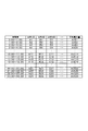
一方、S3において充電容量(残容量)が所定値以下でないと判断される場合には、S3にてNoに進み、満充電可能時間帯の特定処理を行う(S4)。この特定処理は、電池3を満充電とすることのできる時間帯を特定する処理であり、本参考例では図3のような流れでなされる。具体的には、まず、接続開始時から時間的に最も近い不使用予想時間帯を判断対象として確認する(S10)。この不使用予想時間帯は、二次元コードリーダ1の使用履歴を統計処理した結果(例えば図4のようなデータ)に基づいて、図5のように定められるものである。この例では、一日を複数の時間帯(図4、図5の例では一時間毎の時間帯)に細分化し、統計処理に基づいて各時間帯ごとの予想電力量を算出している。図4の表及び図5のグラフでは、各時間帯と、各時間帯の予想電力量との関係を示している。本参考例では、予想電力量が所定の低レベルとなる時間帯を不使用予想時間帯とすることができ、図5ではその一例として予想電力量が0の時間帯を不使用予想時間帯として、T1〜T5で示している。
On the other hand, if it is determined in S3 that the charge capacity (remaining capacity) is not less than or equal to the predetermined value, the process proceeds to No in S3, and the full chargeable time zone is specified (S4). This specifying process is a process for specifying a time zone in which the
各使用予想時間帯と、各使用予想時間帯における予想電力量とが図5のような関係を示す場合、S10ではこの情報に基づいて直近の不使用予想時間帯を確認する。例えば、接続開始時が15:00である場合には、その後に到来する16:00〜17:00の不使用予想時間帯を「直近の不使用予想時間帯」として把握する。また、接続開始時が16:00である場合、既に不使用予想時間帯となっているため、次の不使用予想時間帯を「直近の不使用予想時間帯」とする。 When each estimated usage time zone and the expected electric energy in each expected usage time zone show the relationship as shown in FIG. 5, in S10, the latest expected unused usage time zone is confirmed based on this information. For example, when the connection start time is 15:00, the estimated unused time zone from 16:00 to 17:00 that arrives thereafter is grasped as the “estimated unused time zone”. Further, when the connection start time is 16:00, since it is already in the expected non-use time zone, the next non-use expected time zone is set as “the latest expected non-use time zone”.
さらに、その対象となる不使用予想時間帯までに消費される予想総電力量を算出する(S20)。S10にて「直近の不使用予想時間帯」を確認した直後では、その直近の不使用予想時間帯までに消費される予想総電力量を算出する。例えば、接続開始時が15:00である場合には、その後に到来する16:00〜17:00の不使用予想時間帯までの予想総電力量を算出する。また、接続開始時が16:00である場合、既に不使用予想時間帯となっているため、その後に到来する20:00〜7:00の不使用予想時間帯までの予想総電力量を算出する。 Further, an expected total amount of power consumed by the target non-use expected time zone is calculated (S20). Immediately after confirming the “estimated expected non-use time zone” in S10, an expected total amount of power consumed up to the nearest expected non-use time zone is calculated. For example, when the connection start time is 15:00, an expected total electric energy up to an estimated unused time zone from 16:00 to 17:00 that arrives thereafter is calculated. In addition, when the connection start time is 16:00, it is already in the expected non-use time zone, so the expected total power amount to the non-use expected time zone from 20:00 to 7:00 that comes after that is calculated. To do.
さらに、その対象の不使用予想時間帯において充電を行うとした場合に必要となる充電時間を算出する(S30)。具体的には、現在の充電容量(残容量)からS20にて算出された予想総電力量に応じた容量を減算し、その減算後の容量に基づいて、満充電までに必要となる充電時間を算出する。 Further, the charging time required when charging is performed in the target non-use expected time zone is calculated (S30). Specifically, the charging time required for full charging is subtracted from the current charging capacity (remaining capacity) according to the expected total power calculated in S20, and based on the capacity after the subtraction. Is calculated.
そして、その算出された充電時間に基づき、対象となる不使用予想時間帯において満充電できるかどうかを判断する(S40)。即ち、S30にて算出された充電時間(即ち、満充電までの必要時間)が、その対象となる不使用予想時間帯の時間幅以下であるかどうかを判断し、充電時間(必要時間)が対象となる不使用予想時間帯の時間幅以下の場合には満充電可能と判断し、S40にてYesに進み、当該サブルーチンを終了する。一方、充電時間(必要時間)が不使用予想時間帯の時間幅を超える場合には、満充電不可としてS40にてNoに進み、その次に到来する不使用予想時間帯を確認して対象を当該次の不使用予想時間帯に移し、S20〜S40の処理を繰り返す。 Then, based on the calculated charging time, it is determined whether or not it can be fully charged in a target non-use expected time zone (S40). That is, it is determined whether or not the charging time calculated in S30 (that is, the necessary time until full charge) is equal to or less than the time width of the target non-use expected time zone, and the charging time (required time) is If it is less than or equal to the target non-use expected time zone, it is determined that the battery can be fully charged, the process proceeds to Yes in S40, and the subroutine ends. On the other hand, if the charging time (required time) exceeds the time width of the expected non-use time zone, the process proceeds to No in S40 as a full charge is impossible, and the next non-use expected time zone that comes next is confirmed It shifts to the next expected non-use time zone, and repeats the processes of S20 to S40.
このようにして満充電可能時間帯が特定された後、S5にて現在の状態が充電が必要な場合であるか否かを判断する。
本参考例では、後述する統計処理に基づいて、図5のように当該二次元コードリーダ1の使用が予想される1又は複数の使用予想時間帯を推測しており、さらに各使用予想時間帯において使用される予想電力量を推測している。そして、接続開始時に行われるS5の処理では、各使用予想時間帯と、各使用予想時間帯において使用される予想電力量と、に基づき、接続開始時から当該接続開始時の次に到来する満充電可能時間帯までに使用される予想総電力量を推測し、その予想総電力量が、当該接続開始時における残容量に応じた供給可能電力量を上回るか否かを判断している。そして、予想総電力量が供給可能電力量を上回る場合には、次の満充電可能時間帯までに電池切れが生じることが予想されるため、S5において充電が必要と判断し、Yesに進んで充電処理を行う(S6)。即ち、予想総電力量が供給可能電力量を上回る場合には、次の満充電可能時間帯の到来を待たずに充電電流の供給を開始するように制御している。
After the fully chargeable time zone is specified in this way, it is determined in S5 whether the current state is a case where charging is required.
In this reference example , one or a plurality of expected use time zones in which the use of the two-
S5の処理について図5を参照し例を挙げて説明すると、例えば、接続開始時点が14:00であり、その時点での残容量がX1で、その残容量X1によって供給可能な供給可能電力量がY1であったとする。そして、図2、図3の処理によって、満充電可能時間帯が20:00〜7:00として特定されたとする。このような環境下でS5の処理を行う場合、満充電可能時間帯(20:00〜7:00)までの各使用予想時間帯(14:00〜16:00、17:00〜20:00)において使用される予想電力量(即ち、14:00〜16:00の予想電力量、及び17:00〜20:00の予想電力量)を合計して予想総電力量とし、この予想総電力量が、接続開始時(即ち14:00の時点)での供給可能電力量Y1を上回るか否かを判断する。そして、上回る場合にはS5において充電が必要と判断され、充電処理が行われることとなる(S6)。なお、制御回路40及び図2のプログラムは「予想総電力量推測手段」の一例に相当する。
The process of S5 will be described with an example with reference to FIG. 5. For example, the connection start time is 14:00, the remaining capacity at that time is X1, and the suppliable power amount that can be supplied by the remaining capacity X1 Is Y1. Then, it is assumed that the fully chargeable time zone is specified as 20:00 to 7:00 by the processing of FIGS. When the process of S5 is performed in such an environment, each expected use time zone (14: 0 to 16:00, 17:00 to 20:00) until a fully chargeable time zone (20: 00 to 7:00). ) Is used as the total predicted power amount (that is, the predicted power amount from 14:00 to 16:00 and the predicted power amount from 17:00 to 20:00). It is determined whether or not the amount exceeds the suppliable power amount Y1 at the start of connection (that is, at 14:00). If it exceeds, it is determined that charging is required in S5, and the charging process is performed (S6). The
一方、S5において充電が必要でないと判断される場合にはNoに進み当該処理を終了する。即ち、次に到来する満充電可能時間帯までに予想される予想総電力量が供給可能電力量を上回らない場合には、現時点での充電が必要ないと判断し、S5にてNoに進むようにしている。
なお、図2の処理は、二次元コードリーダ1が充電器100に接続された接続開始時以外でも実施できる。例えば、二次元コードリーダ1が充電器100に接続されている接続中に、所定時間おきに実行するようにしてもよい。
On the other hand, if it is determined in S5 that charging is not required, the process proceeds to No and ends the process. That is, if the predicted total power amount expected by the next full chargeable time zone does not exceed the suppliable power amount, it is determined that charging at this time is not necessary, and the process proceeds to No in S5. Yes.
Note that the process of FIG. 2 can be performed at a time other than the start of connection when the two-
このように本参考例では、後述する統計処理に基づいて、二次元コードリーダ1の不使用が予想される不使用予想時間帯を推測し、その不使用予想時間帯のうち、必要時間よりも時間幅が長い満充電可能時間帯を特定するようにしている。なお、制御回路40及び図2、図3に示すプログラムが「特定手段」の一例に相当する。
また、本参考例では、二次元コードリーダ1が充電器100に接続された接続開始時において、「残容量検出手段」に相当する制御回路40によって電池3の残容量を検出し、さらに、その接続開始時の残容量に基づいて満充電までの必要時間を検出している。即ち、制御回路40は、電池3の残容量に基づいて満充電までの必要時間を検出する「必要時間検出手段」の一例に相当している。
さらに、このように「必要時間の検出」を行った上で、「特定手段」に相当する制御回路40及びプログラムにより、接続開始時の必要時間に基づいて満充電可能時間帯を特定し、さらにその特定された満充電可能時間帯において充電電流の供給を行うように制御回路40及び充電制御回路5によって充電時期を制御している。
As described above, in this reference example , an expected non-use time zone in which the non-use of the two-
In this reference example , when the two-
Further, after performing the “required time detection” in this way, the
3.統計処理
次に、統計処理について説明する。図6は、統計処理の流れを例示するフローチャートである。統計処理は、例えば、使用者によって統計処理モードが指示された場合に開始される処理であり、まず、時計部11からの時刻情報に基づいて、初回の検出時刻が到来したか否かを判断する(S100)。本参考例では、例えば、0:00から24:00まで一時間毎に検出時刻が設定されており、0:00、1:00、2:00と一時間おきに検出が行われるようになっており、S100では、設定されるいずれかの検出時刻が到来したか否かが判断される。なお、初回の検出時刻が到来するまではS100にてNoに進み続け、待機状態となる。
3. Statistical processing Next, statistical processing will be described. FIG. 6 is a flowchart illustrating the flow of statistical processing. The statistical processing is processing that is started, for example, when the statistical processing mode is instructed by the user. First, based on the time information from the
一方、初回の検出時刻が到来したときには、S100にてYesに進み、その初回検出時刻での充電容量(残容量)の検出がなされる(S110)。このときの充電容量は、前回検出充電容量Wn-1として設定され、メモリ35に記憶される。
On the other hand, when the first detection time arrives, the process proceeds to Yes in S100, and the charge capacity (remaining capacity) at the first detection time is detected (S110). The charge capacity at this time is set as the previously detected charge capacity Wn−1 and stored in the
その後、二次元コードリーダ1と充電器100とが非接続接続であるか否かの確認がなされる(S120)。二次元コードリーダ1が充電器100と接続されておらず、非接続状態である場合にはS120にてYesに進み、当該二次元コードリーダ1が使用されたものとして使用フラグを1に設定する。なお、次の検出時刻が到来するまではS140にてNoに進み続け、S120の判断処理が繰り返されるため、次の検出時刻までのいずれかの時期に非接続状態が発生すれば使用フラグが1に設定されることとなる。なお、次の検出時刻の到来まで二次元コードリーダ1と充電器100とが非接続状態とならなかった場合(即ち、接続され続けた場合)、S120にてNoに進み続けるため、使用フラグはデフォルトの状態(本参考例では0の状態)が維持される。
Thereafter, it is confirmed whether or not the two-
そして、次の検出時刻が到来すると、S140にてYesに進み、前時間帯(前回充電容量Wn-1の検出時刻からその次の検出時刻までの時間帯)において二次元コードリーダ1が使用されたか否かの判断がなされる(S150)。二次元コードリーダ1が使用されたか否かの判断は使用フラグが1となっているか否かを判断することにより行われ、使用フラグが0である場合には前時間帯に使用がなかったものとしてS150にてNoに進み、その前時間帯について不使用である旨の記録がなされる。具体的には、その前時間帯について消費電力量が0である旨が記録される。
When the next detection time comes, the process proceeds to Yes in S140, and the two-
一方、前時間帯において二次元コードリーダ1が使用されたと判断される場合(即ち、使用フラグが1である場合)にはS150にてYesに進み、現在の充電容量(即ち、直近の検出時刻での充電容量)Wnを確認する。さらに、前回充電容量Wn-1と現在の充電容量nとの差を求め、この差に基づいて消費電力量を算出する。さらに、算出された消費電力量を前時間帯と対応付けて記録する。消費電力量の記録は、例えば図7のようになされる。図7では、時間帯と消費電力量とを対応付けて記録するデータ構成例を示しており、S180の記録の際にはS170にて算出された消費電力量が前時間帯と対応付けて記録され、他方、S210の記録の際には、「0」の値が前時間帯と対応付けて記録される。
On the other hand, when it is determined that the two-
その後、現在の充電容量(直近の検出時刻での充電容量)Wnを前回充電容量Wn-1に設定し(S190)、使用フラグを0にリセットする(S200)。その後、統計処理の終了時期に至ったか否かが判断される(S220)。終了時期の設定は様々な方法が考えられるが、例えば、当該統計処理の開始時刻から一定時間経過した時期(例えば1週間)などとしたり、或いは、検出時刻の到来が一定回数に達した時期などとすることができる。なお、終了時期に至ってないと判断される場合には、S220にてNoに進み、S120以降の処理を繰り返し、次の時間帯での消費電力量を求め、記録することとなる。 Thereafter, the current charging capacity (charging capacity at the latest detection time) Wn is set to the previous charging capacity Wn-1 (S190), and the use flag is reset to 0 (S200). Thereafter, it is determined whether or not the end time of the statistical processing has been reached (S220). There are various methods for setting the end time. For example, the time when a certain time has elapsed from the start time of the statistical processing (for example, one week) or the time when the detection time has reached a certain number of times. It can be. If it is determined that the end time has not been reached, the process proceeds to No in S220, and the processing after S120 is repeated to obtain and record the power consumption amount in the next time zone.
終了時期に至ったと判断される場合には、S220にてYesに進み、時間帯毎の各予想電力量を算出する。本参考例では、図7に示すように、複数日について時間帯ごとの消費電力量が記憶されるようになっているため、S220では、各時間帯ごとに1日あたりの平均消費電力量を算出し(図7右端欄参照)、その平均消費電力量を予想電力量として、図4のように設定する。即ち、各平均消費電力量AVE1、AVE2・・・が、図4の各予想電力量W1、W2・・・として設定される。 If it is determined that the end time has been reached, the process proceeds to Yes in S220, and each predicted power amount for each time period is calculated. In this reference example , as shown in FIG. 7, since the power consumption for each time zone is stored for a plurality of days, in S220, the average power consumption per day is calculated for each time zone. Calculation is performed (see the rightmost column in FIG. 7), and the average power consumption is set as the predicted power consumption as shown in FIG. That is, each average power consumption AVE1, AVE2,... Is set as each predicted power consumption W1, W2,.
このように、統計処理では、時計部11にて発生する時刻情報に基づいて充電器100が充電端子9に接続されていない非接続時間帯を特定すると共に、当該非接続時間帯を、二次元コードリーダ1が実際に使用された使用時間帯として使用時間帯データを生成している(即ち、S170にて消費電力量を算出し、この消費電力量を時間帯と対応付けて記録することで使用時間帯を特定できるようにしている)。また、時計部11にて発生する時刻情報に基づいて充電器100が充電端子9に接続される接続時間帯を特定すると共に、当該接続時間帯を、二次元コードリーダ1が実際に使用されなかった不使用時間帯として不使用時間帯データを生成している(即ち、S210において時間帯と対応付けて消費電力量を0と記録することで、不使用時間帯を特定できるようにしている)。そして、複数日にて生成された使用時間帯データ及び不使用時間帯データに基づいて更なる統計処理(即ち平均消費電力量の算出)を行うようにしている。なお、制御回路40及び図6のプログラムは、二次元コードリーダ1が充電器100に接続された時刻に基づいて、二次元コードリーダ1の使用時間帯に関する統計処理を行う「統計処理手段」の一例に相当する。また、平均消費電力量が所定の低レベル(例えばゼロレベル)となる時間帯が「不使用予想時間帯」に相当しており、制御回路40及び図6のプログラムは、「不使用予想時間帯推測手段」の一例に相当する。
As described above, in the statistical processing, the non-connection time zone in which the
また、本参考例では、統計処理に基づいて、当該二次元コードリーダ1の使用が予想される複数の使用予想時間帯(即ち、平均消費電力量が0レベルではない時間帯)を推測でき、さらに各使用予想時間帯において使用される予想電力量(平均消費電力量)を推測できるようになっている。制御回路40及び図6のプログラムは、「使用予想時間帯推測手段」「予想電力量推測手段」の一例に相当する。
Further, in this reference example , based on statistical processing, a plurality of expected usage time zones in which the use of the two-
以上のように、本参考例の構成によれば、二次元コードリーダ1が充電器100に接続された時刻に基づいて、二次元コードリーダ1の使用時間帯に関する統計処理を行い、不使用が予想される不使用予想時間帯を推測しており、このような「統計処理」及び「不使用予想時間帯の推測」によって満充電可能時間帯を特定できるようになっている。そして、このように特定される満充電可能時間帯において充電電流の供給を行うように充電時期を制御している。即ち、満充電可能時間帯の到来を待ってから充電を開始するように充電開始時期を遅らせており、この構成によれば、放電深度の低い状態での充放電の繰り返しを抑制でき、かつ不十分な充電のまま使用される事態が生じにくくなる。
As described above, according to the configuration of this reference example , the statistical processing related to the usage time zone of the two-
また、接続開始時において、次に到来する満充電可能時間帯までの予想総電力量が、当該接続開始時の残容量に応じた供給可能電力量を上回るか否かを判断し、上回る場合には、次の満充電可能時間帯の到来を待たずに充電電流の供給を開始するようにしている。即ち、供給可能電力量を上回るような使用が予想される場合には、それを見越して例外的に充電開始時期を早めるようにしており、この構成によれば使用中に電池切れが生じにくくなる Also, at the start of connection, it is determined whether or not the expected total power amount until the next full chargeable time zone exceeds the available power amount according to the remaining capacity at the start of the connection. Starts supplying the charging current without waiting for the arrival of the next fully chargeable time zone. In other words, when the use is expected to exceed the suppliable power amount, the charging start time is exceptionally advanced in anticipation of this, and according to this configuration, it is difficult for the battery to run out during use.
また、複数日にて生成された使用時間帯データ及び不使用時間帯データに基づいて統計処理を行い、当該統計処理に基づいて不使用予想時間帯を推測しており、このようにすれば、得られた不使用予想時間帯がより信頼性の高いものとなる。 In addition, statistical processing is performed based on the usage time zone data and non-use time zone data generated on multiple days, and the expected non-use time zone is estimated based on the statistical processing. The obtained non-use expected time zone becomes more reliable.
[第2参考例]
次に第2参考例について説明する。図8は、第2参考例での充電制御の流れを例示するフローチャートである。
第2参考例は、第1参考例において図2に示した充電制御の流れを図8のようにした点のみが第1参考例と異なり、それ以外は第1参考例と同一である。よって、同一の部分については第1参考例の図1、図3〜図7を参照し、詳細な説明は省略する。
なお、図8において、S301〜S306は図2のS1〜S6と同様であり、まず、充電器100(図1)が接続されたか否かの判断処理が行われ(S301)、その後、電池3の充電容量(残容量)が確認される(S302)。さらに、充電容量(残容量)が所定値以下であるか判断される(S303)。充電容量(残容量)が所定値以下である場合にはすぐにでも充電を行う必要があるため、S303にてYesに進み、充電処理が行われる(S306)。この「所定値」は、第1参考例と同様に、S303の判断を行うための値として予めメモリ35に記憶されている。
[Second Reference Example ]
Next, a second reference example will be described. FIG. 8 is a flowchart illustrating the flow of charge control in the second reference example .
The second reference example, the flow of charging control shown in FIG. 2 in the first reference example only the points shown in FIG. 8 is different from the first reference example, but is otherwise identical to the first reference example. Therefore, for the same parts, refer to FIG. 1 and FIG. 3 to FIG. 7 of the first reference example , and the detailed description is omitted.
8, S301 to S306 are the same as S1 to S6 in FIG. 2. First, a determination process is performed as to whether or not the charger 100 (FIG. 1) is connected (S <b> 301), and then the
一方、S303において充電容量(残容量)が所定値以下でないと判断される場合には、S303にてNoに進み、満充電可能時間帯の特定処理を行う(S304)。この特定処理は、第1参考例のS4(図2)、図3と同様である。そして、満充電可能時間帯が特定された後、S305にて現在の状態が充電が必要な場合であるか否かを判断する。即ち、第1参考例と同様の方法により、次の満充電可能時間帯までに電池切れが予想されるか否かを判断し、電池切れが予想され、充電が必要である場合にはS305においてYesに進んで充電処理を行う(S306)。 On the other hand, if it is determined in S303 that the charge capacity (remaining capacity) is not less than or equal to the predetermined value, the process proceeds to No in S303, and the full chargeable time zone is specified (S304). This specifying process is the same as S4 (FIG. 2) and FIG. 3 of the first reference example . Then, after the fully chargeable time zone is specified, it is determined in S305 whether the current state is a case where charging is necessary. That is, by the same method as in the first reference example , it is determined whether or not the battery is expected to be exhausted by the next fully chargeable time zone. It progresses to Yes and performs a charge process (S306).
充電が必要でない場合にはS305にてNoに進み、二次元コードリーダ1と充電器100とが接続され続けているか判断する。接続状態である場合にはS307にてYesに進み、充電容量(残容量)が所定値以下であるか判断する(S308)。充電容量(残容量)が所定値以下でない場合にはS308にてNoに進み、S304にて特定された満充電可能時間帯となったか否かが判断される。即ち、本参考例では、S304にて特定された満充電可能時間帯となるまで、もしくは充電容量(残容量)が所定値以下となるまでS307〜S309の処理が繰り返されるようになっており、満充電可能時間帯に至るまでに充電容量(残容量)が所定値以下となった場合にはS308にてYesに進み、充電処理を行う(S306)。また、満充電可能時間帯に至った場合にはS309にてYesに進み、充電処理を行う(S306)。このように本参考例では、実際に満充電可能時間帯となるまで待ってから充電を開始するように充電開始時期を遅らせている。
If charging is not necessary, the process proceeds to No in S305 to determine whether the two-
[第1実施形態]
次に第1実施形態について図9等を参照して説明する。図9は、第1実施形態における満充電可能時間帯を特定する処理を例示するフローチャートである。
なお、本実施形態では、図3の処理を図9の処理に変更した点が、第2参考例と異なり、それ以外は第2参考例と同様である。なお、第2参考例は、図2以外は第1参考例と同一であるため、図1、図4〜図7は第1参考例を参照し、充電処理については第2参考例の図8を参照することとする。
First Embodiment
Next, a first embodiment will be described with reference to FIG. FIG. 9 is a flowchart illustrating a process of specifying a fully chargeable time zone in the first embodiment.
In the present embodiment, that have changed the process of FIG. 3 in the process of FIG. 9 differs from the second reference example, but is otherwise similar to the second embodiment. Since the second reference example is the same as the first reference example except for FIG. 2, FIGS. 1 and 4 to 7 refer to the first reference example , and the charging process is illustrated in FIG. 8 of the second reference example . Refer to
本実施形態では、第1参考例において図3のように行っていた満充電可能時間帯の特定処理(図8のS304の処理)を図9のような流れで行う。
S410〜S450は、図3のS10〜S50と同様であり、まず、接続開始時から時間的に最も近い不使用予想時間帯を判断対象として確認し(S410)、その対象となる不使用予想時間帯までに消費される予想総電力量を算出する(S420)。さらに、その対象の不使用予想時間帯において充電を行うとした場合に必要となる充電時間を算出する(S430)。具体的には、第1参考例と同様であり、現在の充電容量(残容量)からS420にて算出された予想総電力量に応じた容量を減算し、その減算後の容量に基づいて、満充電までに必要となる充電時間を算出する。そして、その算出された充電時間に基づき、対象となる不使用予想時間帯において満充電できるかどうかを判断する(S440)。即ち、S430にて算出された充電時間(即ち、満充電までの必要時間)が、その対象となる不使用予想時間帯の時間幅以下であるかどうかを判断し、充電時間(必要時間)が対象とする不使用予想時間帯の時間幅を超える場合には、満充電不可としてS440にてNoに進む。そして、その次に到来する不使用予想時間帯を確認して対象を当該次の不使用予想時間帯に移し、S420以降の処理を繰り返す。
In the present embodiment, the full chargeable time zone specifying process (the process of S304 of FIG. 8) performed as shown in FIG. 3 in the first reference example is performed according to the flow shown in FIG.
S410 to S450 are the same as S10 to S50 in FIG. 3. First, the estimated non-use time zone that is closest in time from the start of connection is confirmed as a determination target (S410), and the non-use expected time that is the target is confirmed. The expected total power consumed by the band is calculated (S420). Further, the charging time required when charging is performed in the target non-use expected time zone is calculated (S430). Specifically, it is the same as in the first reference example, and subtracts the capacity according to the expected total power calculated in S420 from the current charge capacity (remaining capacity), and based on the capacity after the subtraction, Calculate the charging time required to fully charge. Then, based on the calculated charging time, it is determined whether or not it can be fully charged in the target non-use expected time zone (S440). That is, it is determined whether the charging time calculated in S430 (that is, the necessary time until full charge) is equal to or less than the time width of the target non-use expected time zone, and the charging time (required time) is determined. When the time width of the target non-use expected time zone is exceeded, it is determined that full charge is impossible and the process proceeds to No in S440. Then, the expected non-use time zone that comes next is confirmed, the target is moved to the next non-use expected time zone, and the processing from S420 is repeated.
一方、充電時間(必要時間)が対象となる不使用予想時間帯の時間幅以下の場合には満充電可能と判断し、S440にてYesに進み、その不使用予想時間帯までの予想総電力量が現在の充電容量(残容量)に応じた供給可能電力量を上回るか否かを判断し、上回らない場合にはS460にてNoに進み、その不使用予想時間帯を満充電可能時間帯として記録する(S470)。一方、S460において、その不使用予想時間帯までの予想総電力量が現在の充電容量(残容量)に応じた供給可能電力量を上回ると判断される場合には、S460にてNoに進み、当該サブルーチンを終了する。 On the other hand, if the charging time (required time) is equal to or less than the target non-use expected time zone, it is determined that the battery can be fully charged, and the process proceeds to Yes in S440 and the expected total power up to the non-use expected time zone. It is determined whether or not the amount exceeds the suppliable power amount according to the current charge capacity (remaining capacity), and if not exceeded, the process proceeds to No in S460, and the expected non-use time zone is set as the time when full charge is possible Is recorded (S470). On the other hand, in S460, when it is determined that the predicted total power amount up to the expected non-use time zone exceeds the suppliable power amount corresponding to the current charge capacity (remaining capacity), the process proceeds to No in S460, The subroutine ends.
S470にて満充電可能時間帯を記録した後は、S450にて次の不使用予想時間帯を確認し、S420以降の処理を繰り返すこととなる。その繰り返された処理で、満充電可能時間帯が新たに特定され、その満充電可能時間帯までの予想総電力量が現在の充電容量(残容量)に応じた供給可能電力量を上回らない場合にはS460にてNoに進んで満充電可能時間帯が更に記録されることとなる。 After the full chargeable time zone is recorded in S470, the next expected non-use time zone is confirmed in S450, and the processing after S420 is repeated. In the repeated process, a fully chargeable time zone is newly specified, and the expected total power amount up to the full chargeable time zone does not exceed the available power amount according to the current charge capacity (remaining capacity) In step S460, the process proceeds to No, and the full chargeable time zone is further recorded.
上記処理では、接続開始時の後に到来する複数の満充電可能時間帯を特定し、接続開始時から各満充電可能時間帯までに使用が予想される各予想総電力量を、各満充電可能時間帯ごとにそれぞれ推測している(S420の処理参照)。なお本実施形態でも、第1参考例と同様の統計処理(図6、図7参照)に基づいて、二次元コードリーダ1の使用が予想される1又は複数の使用予想時間帯を推測しており、各使用予想時間帯において使用される予想電力量を推測している。さらに、各使用予想時間帯において使用される予想電力量に基づき、接続開始時の後に到来する各満充電予想時間帯までの各予想総電力量をそれぞれ推測している。なお、本実施形態では、制御回路40及び図9のプログラムが「特定手段」の一例に相当している。
In the above process, multiple full chargeable time zones that arrive after the start of connection are identified, and each estimated total power amount that is expected to be used from the start of connection to each full chargeable time zone can be fully charged. Each time zone is estimated (see processing in S420). In the present embodiment, one or a plurality of expected use time zones in which the use of the two-
本実施形態の充電制御は第2参考例と同様に図8のように行われるようになっており、そのうちのS309の判断処理では、S470にて記録された満充電可能時間帯のうちの最も後に到来する時間帯に至ったか否かが判断され、至った場合にはS309にてYesに進み、充電処理が行われる(S306)。即ち、本実施形態では、図9の特定処理によって特定された複数の満充電可能時間帯の中から、満充電可能時間帯の到来までの各予想総電力量が、接続開始時の残容量に応じた供給可能電力量を上回らない1又は複数の特定時間帯を選び、接続開始時から最も後に到来する特定時間帯において充電電流の供給を行うように充電時期を制御している。図5を参照して説明すると、例えば、接続開始時が10:00であり、特定時間帯(満充電可能時間帯のうち、到来までの予想総電力量が、接続開始時の残容量に応じた供給可能電力量を上回らない時間帯)が11:00〜14:00、20:00〜7:00である場合には、最も後に到来する20:00〜7:00の時間帯に充電電流の供給を行うように充電時期が制御されることとなる。なお、本実施形態では、各制御回路40及び図9のプログラムが「各予想総電力量推測手段」の一例に相当する。
The charging control of the present embodiment is performed as shown in FIG. 8 as in the second reference example, and in the determination process of S309, the most fully chargeable time zone recorded in S470 is included. It is determined whether or not a time zone that will arrive later is reached. If the time has arrived, the process proceeds to Yes in S309, and the charging process is performed (S306). That is, in the present embodiment, the predicted total power amount from the plurality of full chargeable time zones specified by the specifying process of FIG. 9 to the arrival of the full chargeable time zone is the remaining capacity at the start of connection. One or a plurality of specific time zones that do not exceed the corresponding suppliable power amount are selected, and the charging timing is controlled so that the charging current is supplied in the specific time zone that comes most recently from the start of connection. Referring to FIG. 5, for example, the connection start time is 10:00, and the expected total amount of power until arrival in a specific time zone (full chargeable time zone depends on the remaining capacity at the start of connection) In the case of 11: 0 to 14:00, 20:00 to 7:00, the charging current is the latest time of 20:00 to 7:00. The charging time is controlled so as to supply the power. In the present embodiment, each
以上のように、本実施形態では、複数の満充電可能時間帯の中から、到来までの予想総電力量が接続開始時の供給可能電力量を上回らない1又は複数の特定時間帯を選び、最も後に到来する特定時間帯において充電電流が供給されるように制御を行っている。従って、使用中に電池切れが生じにくい程度に充電開始時期を後延ばしにでき、かつ充電の際に十分な充電時間を確保できるようになる。 As described above, in the present embodiment, one or more specific time zones in which the expected total power amount until arrival is higher than the suppliable power amount at the start of connection are selected from a plurality of full chargeable time zones, Control is performed so that the charging current is supplied in a specific time zone that comes later. Therefore, the charging start timing can be postponed to such an extent that the battery does not run out during use, and a sufficient charging time can be secured during charging.
[第3参考例]
次に第3参考例について説明する。
本参考例では、充電電流の供給を行おうとする満充電可能時間帯において電気料金が高く設定される時間帯(第一時間帯)と安く設定される時間帯(第二時間帯)とが含まれる場合に、その満充電可能時間帯において第二時間帯が最も多くなる時間帯を選択して充電電流の供給を行うように制御している点が第2参考例と異なり、それ以外は第2参考例と同一である。即ち、図1、図3〜図7については第1参考例と同一であり、制御の流れは基本的に図8と同様で、S309からS306に至るまでの間に、第二時間帯の比率が最も多くなる時間帯を選択する処理を行うようにしている点(図示略)のみが図8と異なっている。
[ Third reference example ]
Next, a third reference example will be described.
This reference example includes the time zone (first time zone) where the electricity rate is set high and the time zone (second time zone) where it is set cheaply in the full chargeable time zone where the charging current is to be supplied. Is different from the second reference example in that the charging time is supplied by selecting the time zone in which the second time zone is the largest in the full chargeable time zone. 2 Same as the reference example . That is, FIGS. 1 and 3 to 7 are the same as those in the first reference example , the control flow is basically the same as in FIG. 8, and the ratio of the second time zone between S309 and S306. 8 is different from FIG. 8 only in that processing for selecting the time zone in which the number of times is the largest is performed (not shown).
本参考例では、電気料金が、第一基準で定められる第一時間帯と、第一基準よりも安い第二基準で定められる第二時間帯と、を特定可能な時間帯データがメモリ35(メモリ35は「時間帯データ記憶手段」の一例に相当する)に記憶されており、図8のS309において満充電可能時間帯に至ったと判断された場合、その満充電可能時間帯に第二時間帯が含まれるか否かを判断し、含まれないと判断される場合には即座にS306の充電処理が行われる。一方、その満充電可能時間帯に第二時間帯が含まれる場合には、必要時間(満充電のために必要となる時間)を確保できる時間帯であって、かつ第二時間帯の比率が最も多くなる時間帯にシフトさせた上でS306の充電処理が行われる。なお、メモリ35に記憶される時間帯データは、例えば、0:00〜5:00が第二時間帯であり、5:00〜24:00までが第一時間帯であるといったデータである。
In this reference example , the time zone data that can specify the first time zone determined by the first standard and the second time zone defined by the second standard lower than the first standard is stored in the memory 35 ( The
より具体的な例を挙げると、0:00〜5:00が第二時間帯であり、5:00〜24:00までが第一時間帯であるといった時間帯データが構成され、かつS304にて特定された満充電可能時間帯が例えば22:00〜3:00であるようなケースにおいて、満充電のための必要時間(図3のS30にて算出された時間)が4時間であるような場合には、第二時間帯の比率が最も多くなる23:00〜3:00にシフトさせて充電電流の供給を行うこととなる。 As a more specific example, time zone data is configured such that 0:00 to 5:00 is the second time zone, and 5:00 to 24:00 is the first time zone, and S304 is set. In the case where the full chargeable time zone specified in the above is, for example, 22:00 to 3:00, the necessary time for full charge (time calculated in S30 in FIG. 3) seems to be 4 hours. In this case, the charging current is supplied by shifting to 23:00 to 3:00 where the ratio of the second time zone is the largest.
以上のように、本参考例では、満充電可能時間帯において、満充電までの必要時間を確保できる時間帯であって、かつ第二時間帯(電気料金が比較的安い時間帯)の比率が最も多くなる時間帯を選択し、充電電流の供給を行うように制御しているため、使用者に特別な負担を強いることなく電気料金をより安価にすることができる。 As described above, in this reference example , in the fully chargeable time zone, the ratio of the second time zone (a time zone where the electricity rate is relatively low) that can secure the necessary time until full charge is obtained. Since the control is performed so that the charging time is supplied by selecting the time period in which the number of times increases, it is possible to reduce the electricity charge without imposing a special burden on the user.
[他の実施形態]
本発明は上記記述及び図面によって説明した実施形態に限定されるものではなく、例えば次のような実施形態も本発明の技術的範囲に含まれる。
[Other Embodiments]
The present invention is not limited to the embodiments described with reference to the above description and drawings. For example, the following embodiments are also included in the technical scope of the present invention.
上記実施形態に用いられる「統計処理手段」は、統計処理の一例として、各時間帯毎の消費電力量のデータを蓄積し、平均値を算出する処理を行っていたが、別の手法を用いてもよい。例えば、消費電力量のデータを各時間帯ごとに蓄積し、各時間帯毎に得られたデータの最大値を算出してもよい。この場合、「予想電力量推測手段」は、各時間帯の最大値を予想電力量と推測するように構成できる。また、「不使用予想時間帯推測手段」は、各時間帯の最大値が所定の低レベルの時間帯(例えば最大値が0の時間帯)を不使用予想時間帯として推測するように構成できる。 As an example of statistical processing, the “statistic processing means” used in the above embodiment accumulates power consumption data for each time period and performs processing for calculating an average value. However, another method is used. May be. For example, power consumption data may be accumulated for each time period, and the maximum value of the data obtained for each time period may be calculated. In this case, the “expected power amount estimation means” can be configured to estimate the maximum value of each time zone as the expected power amount. Further, the “unusable expected time zone estimation means” can be configured to estimate a time zone in which the maximum value of each time zone is a predetermined low level (for example, a time zone in which the maximum value is 0) as an expected unused time zone. .
上記実施形態で用いられる「統計処理手段」は、消費電力量のデータを一時間単位で蓄積する例を示したが、これよりも短い時間幅でデータを蓄積(例えば30分毎に消費電力量のデータを蓄積)してもよく、これよりも長い時間幅(例えば2時間毎)に消費電力量のデータを蓄積してもよい。 The “statistical processing means” used in the above embodiment has shown an example in which power consumption data is accumulated in units of one hour. However, data is accumulated in a shorter time width (for example, power consumption every 30 minutes). May be stored), and power consumption data may be stored over a longer time span (for example, every two hours).
上記実施形態で用いられる「不使用予想時間帯推測手段」は、予想電力量が0の時間帯を不使用予想時間帯と推測していたが、予想電力量が予め定められた一定値以下の時間帯を不使用予想時間帯と推測してもよい。 The “unusable expected time zone estimation means” used in the above embodiment has estimated that the time zone in which the predicted power amount is 0 is the expected unused time zone, but the expected power amount is a predetermined value or less. The time zone may be estimated as a non-use expected time zone.
第1実施形態では、「特定手段」が、接続開始時において、当該接続開始時の後に到来する複数の満充電可能時間帯を特定し、「統計処理手段」による統計処理に基づいて、「使用予想時間帯推測手段」が、携帯端末の使用が予想される1又は複数の使用予想時間帯を推測し、「予想電力量推測手段」が、各使用予想時間帯において使用される予想電力量を推測し、「各予想総電力量推測手段」が、各使用予想時間帯において使用される予想電力量に基づき、接続開始時から各満充電可能時間帯までに使用が予想される各予想総電力量を、各満充電可能時間帯ごとにそれぞれ推測している。そして、「充電制御手段」は、接続開始時において、特定手段により特定された複数の満充電可能時間帯の中から、満充電可能時間帯の到来までの各予想総電力量が、接続開始時の残容量に応じた供給可能電力量を上回らない1又は複数の特定時間帯を選び、接続開始時から最も後に到来する特定時間帯において充電電流の供給を行うように充電時期を制御する構成とされている。
このような第1実施形態の構成を若干変更することもできる。例えば、「特定手段」「統計処理手段」「予想電力量推測手段」「各予想総電力量推測手段」を第1実施形態と同様とし、充電制御手段の構成を変更してもよい。具体的には、充電制御手段を、「接続開始時から最も後に到来する特定時間帯において充電電流の供給を行うように充電時期を制御する」構成とせず、「複数の特定時間帯において電気料金が他の時間帯(即ち第一時間帯)よりも相対的に安い第二時間帯が含まれる場合、その第二時間帯を含んだ特定時間帯において充電電流の供給を行うように充電時期を制御する」構成としてもよい。
In the first embodiment, the “specifying unit” specifies a plurality of full chargeable time zones that arrive after the start of connection at the start of connection, and uses “use” based on statistical processing by the “statistic processing unit”. The “expected time zone estimation means” estimates one or more expected usage time zones in which the mobile terminal is expected to be used, and the “expected power amount estimation means” determines the expected power amount used in each expected usage time zone. Each estimated total power that is expected to be used by each “estimated total power estimation means” from the start of connection to each full chargeable time zone based on the expected power usage in each expected usage time zone The amount is estimated for each full chargeable time zone. Then, the “charge control means” indicates that each estimated total power amount from the plurality of full chargeable time zones specified by the specifying means at the start of connection until the arrival of the full chargeable time zone is Selecting one or a plurality of specific time zones that do not exceed the suppliable power amount according to the remaining capacity of the battery, and controlling the charging timing so as to supply the charging current in the specific time zone that comes most recently from the start of connection; Has been.
The configuration of the first embodiment can be slightly changed. For example, “specification means”, “statistical processing means”, “expected power amount estimation means”, and “estimated total power amount estimation means” may be the same as in the first embodiment, and the configuration of the charge control means may be changed. Specifically, the charging control means is not configured to “control the charging timing so as to supply the charging current in the specific time zone that comes most recently from the start of the connection”, but the “electricity charge in multiple specific time zones” Is included in the second time zone, which is relatively cheaper than other time zones (ie, the first time zone), the charging time is set so that the charging current is supplied in a specific time zone including the second time zone. It may be configured to “control”.
1…二次元コードリーダ(携帯端末)
3…電池
5…充電制御回路(充電制御手段)
7…検出部(接続検出手段)
9…充電端子
11…時計部(時計手段)
35…メモリ(時間帯データ記憶手段)
40…制御回路(残容量検出手段、必要時間検出手段、充電制御手段、統計処理手段、不使用予想時間帯推測手段、特定手段、使用予想時間帯推測手段、予想電力量推測手段、予想総電力量推測手段、各予想総電力量推測手段)
100…充電器(充電装置)
1 ... Two-dimensional code reader (mobile terminal)
3 ... Battery 5 ... Charge control circuit (charge control means)
7. Detection unit (connection detection means)
9 ... Charging
35. Memory (time zone data storage means)
40 ... Control circuit (remaining capacity detection means, required time detection means, charging control means, statistical processing means, non-use expected time zone estimation means, identification means, expected use time zone estimation means, expected power amount estimation means, expected total power Quantity estimation means, each expected total power estimation means)
100 ... charger (charging device)
Claims (3)
前記充電装置に接続される充電端子と、
前記電池の残容量を検出する残容量検出手段と、
前記電池の残容量に基づいて、満充電までの必要時間を検出する必要時間検出手段と、
前記電池への充電電流の供給を制御する充電制御手段と、
前記充電端子と前記充電装置との接続を検出する接続検出手段と、
前記携帯端末が前記充電装置に接続された時刻を特定する時計手段と、
前記携帯端末が前記充電装置に接続された時刻に基づいて、前記携帯端末の使用時間帯に関する統計処理を行う統計処理手段と、
前記統計処理手段による前記統計処理に基づいて、前記携帯端末の不使用が予想される不使用予想時間帯を推測する不使用予想時間帯推測手段と、
前記不使用予想時間帯のうち、前記必要時間よりも時間幅が長い満充電可能時間帯を特定する特定手段と、
を備え、
前記携帯端末が前記充電装置に接続された接続開始時において、
前記残容量検出手段は、前記携帯端末の前記残容量を検出し、
前記必要時間検出手段は、前記接続開始時の前記残容量に基づいて前記必要時間を検出し、
前記特定手段は、前記接続開始時の前記必要時間に基づいて、前記接続開始時において、当該接続開始時の後に到来する複数の前記満充電可能時間帯を特定する構成をなしており、
更に、前記統計処理手段による前記統計処理に基づいて、前記携帯端末の使用が予想される1又は複数の使用予想時間帯を推測する使用予想時間帯推測手段と、
各使用予想時間帯において使用される予想電力量を推測する予想電力量推測手段と、
前記各使用予想時間帯において使用される前記予想電力量に基づき、前記接続開始時から各満充電可能時間帯までに使用が予想される各予想総電力量を、各満充電可能時間帯ごとにそれぞれ推測する各予想総電力量推測手段と、
を備え、
前記充電制御手段は、前記接続開始時において、
前記特定手段により特定された複数の前記満充電可能時間帯の中から、前記満充電可能時間帯の到来までの前記各予想総電力量が、前記接続開始時の前記残容量に応じた供給可能電力量を上回らない1又は複数の特定時間帯を選び、
前記接続開始時から最も後に到来する前記特定時間帯において前記充電電流の供給を行うように前記充電時期を制御することを特徴とする携帯端末。 A portable terminal equipped with a battery that can be charged by a charging device,
A charging terminal connected to the charging device;
A remaining capacity detecting means for detecting the remaining capacity of the battery;
Based on the remaining capacity of the battery, necessary time detection means for detecting the necessary time until full charge,
Charging control means for controlling supply of charging current to the battery;
Connection detecting means for detecting connection between the charging terminal and the charging device;
Clock means for specifying the time when the portable terminal is connected to the charging device;
Statistical processing means for performing statistical processing on the usage time zone of the mobile terminal based on the time when the mobile terminal was connected to the charging device;
Based on the statistical processing by the statistical processing means, an expected non-use time zone estimation means for estimating an expected non-use time zone where the non-use of the mobile terminal is expected;
A specifying means for specifying a full chargeable time zone having a time width longer than the required time among the expected non-use time zone;
With
At the start of connection when the mobile terminal is connected to the charging device,
The remaining capacity detecting means detects the remaining capacity of the mobile terminal;
The necessary time detecting means detects the necessary time based on the remaining capacity at the start of the connection,
The specifying means is configured to specify a plurality of full chargeable time zones that arrive after the start of connection based on the necessary time at the start of connection,
Furthermore, based on the statistical processing by the statistical processing means, estimated use time zone estimation means for estimating one or a plurality of expected usage time zones in which use of the mobile terminal is expected;
Expected power estimation means for estimating the expected power used in each expected usage time zone;
Based on the expected power amount used in each expected use time zone, each expected total power amount expected to be used from the start of connection until each full chargeable time zone is calculated for each full chargeable time zone. Each estimated total power estimation means for estimating each,
With
The charging control means, at the start of the connection,
The expected total electric energy from the plurality of full chargeable time zones specified by the specifying means to the arrival of the full chargeable time zone can be supplied according to the remaining capacity at the start of the connection. Select one or more specific time zones that do not exceed the amount of power,
The portable terminal , wherein the charging timing is controlled so that the charging current is supplied in the specific time zone that comes most recently from the connection start time .
前記充電制御手段は、
前記時間帯データに基づいて前記第一時間帯と前記第二時間帯とを確認し、
前記充電電流の供給を行おうとする前記満充電可能時間帯において、前記第一時間帯と前記第二時間帯とが含まれる場合、当該満充電可能時間帯において、前記必要時間を確保できる時間帯であって、かつ前記第二時間帯の比率が最も多くなる時間帯を選択し、前記充電電流の供給を行うように制御することを特徴とする請求項1に記載の携帯端末。 Time zone data storage means for storing time zone data that can specify a first time zone determined by a first standard and a second time zone defined by a second standard that is lower than the first standard. With
The charge control means includes
Confirm the first time zone and the second time zone based on the time zone data,
When the full chargeable time zone in which the charging current is to be supplied includes the first time zone and the second time zone, the time zone in which the necessary time can be secured in the full chargeable time zone The mobile terminal according to claim 1 , wherein the mobile terminal is controlled to select a time zone in which the ratio of the second time zone is the largest and to supply the charging current .
前記時計手段に基づいて前記携帯端末が前記充電端子に接続されていない非接続時間帯を特定すると共に、当該非接続時間帯を、前記携帯端末が実際に使用された使用時間帯として使用時間帯データを生成する一方、
前記時計手段に基づいて前記携帯端末が前記充電端子に接続される接続時間帯を特定すると共に、当該接続時間帯を、前記携帯端末が実際に使用されなかった不使用時間帯として不使用時間帯データを生成し、
複数日にて生成された前記使用時間帯データ及び前記不使用時間帯データに基づいて前記統計処理を行うことを特徴とする請求項1又は請求項2に記載の携帯端末。 The statistical processing means includes
Based on the clock means, the mobile terminal specifies a non-connection time zone in which the mobile terminal is not connected to the charging terminal, and uses the non-connection time zone as a usage time zone in which the mobile terminal is actually used. While generating data,
A connection time zone in which the mobile terminal is connected to the charging terminal based on the clock means is specified, and the connection time zone is set as a non-use time zone in which the mobile terminal is not actually used. Generate data,
The mobile terminal according to claim 1 or 2 , wherein the statistical processing is performed based on the use time zone data and the non-use time zone data generated on a plurality of days .
Priority Applications (1)
| Application Number | Priority Date | Filing Date | Title |
|---|---|---|---|
| JP2007205191A JP4760800B2 (en) | 2007-08-07 | 2007-08-07 | Mobile device |
Applications Claiming Priority (1)
| Application Number | Priority Date | Filing Date | Title |
|---|---|---|---|
| JP2007205191A JP4760800B2 (en) | 2007-08-07 | 2007-08-07 | Mobile device |
Publications (2)
| Publication Number | Publication Date |
|---|---|
| JP2009042877A JP2009042877A (en) | 2009-02-26 |
| JP4760800B2 true JP4760800B2 (en) | 2011-08-31 |
Family
ID=40443581
Family Applications (1)
| Application Number | Title | Priority Date | Filing Date |
|---|---|---|---|
| JP2007205191A Expired - Fee Related JP4760800B2 (en) | 2007-08-07 | 2007-08-07 | Mobile device |
Country Status (1)
| Country | Link |
|---|---|
| JP (1) | JP4760800B2 (en) |
Families Citing this family (7)
| Publication number | Priority date | Publication date | Assignee | Title |
|---|---|---|---|---|
| EP2020723A3 (en) * | 2007-07-31 | 2012-11-21 | Yamaha Corporation | Battery charger, secondary battery unit and electric apparatus equipped therewith |
| DE102009002466A1 (en) * | 2009-04-17 | 2010-10-21 | Robert Bosch Gmbh | Extended battery diagnosis for traction batteries |
| EP2466719B1 (en) * | 2009-08-11 | 2015-09-30 | Sony Corporation | Electronic device, method for charging electronic device, program, charging control device, and charging control method |
| JP5877360B2 (en) * | 2011-05-26 | 2016-03-08 | パナソニックIpマネジメント株式会社 | Storage battery control system |
| JP5358696B2 (en) * | 2012-01-18 | 2013-12-04 | 中国電力株式会社 | Charge control device for multiple quick chargers and ordinary chargers |
| JP6230446B2 (en) * | 2014-02-26 | 2017-11-15 | シャープ株式会社 | handy terminal |
| CN110556897B (en) * | 2019-09-29 | 2023-07-28 | 密码精灵有限公司 | Charging control method and device for intelligent door lock and intelligent door lock |
Family Cites Families (7)
| Publication number | Priority date | Publication date | Assignee | Title |
|---|---|---|---|---|
| JP2785316B2 (en) * | 1989-04-19 | 1998-08-13 | 株式会社豊田自動織機製作所 | Charger |
| JP2001008376A (en) * | 1999-06-22 | 2001-01-12 | Canon Inc | Apparatus and method for control of charging as well as apparatus with battery |
| JP2001326721A (en) * | 2000-05-15 | 2001-11-22 | Sony Corp | Portable telephone terminal, method for notifying power information and method for limiting additional function |
| JP2003167652A (en) * | 2001-11-30 | 2003-06-13 | Toshiba Corp | Information processor |
| JP4061983B2 (en) * | 2002-06-20 | 2008-03-19 | 日本電気株式会社 | Portable terminal device and charging method thereof |
| JP2004318629A (en) * | 2003-04-18 | 2004-11-11 | Canon Electronics Inc | Electronic device |
| JP2005142796A (en) * | 2003-11-06 | 2005-06-02 | Sharp Corp | Mobile television receiver |
-
2007
- 2007-08-07 JP JP2007205191A patent/JP4760800B2/en not_active Expired - Fee Related
Also Published As
| Publication number | Publication date |
|---|---|
| JP2009042877A (en) | 2009-02-26 |
Similar Documents
| Publication | Publication Date | Title |
|---|---|---|
| JP4760800B2 (en) | Mobile device | |
| US5898290A (en) | Battery pack with capacity and pre-removal indicators | |
| US20040164711A1 (en) | Battery charger and method therefor | |
| EP1598917A2 (en) | Electronic device, battery pack, power-supply controlling method and program for electronic device | |
| JP5787812B2 (en) | Electric forklift and charging system | |
| JP2008295170A (en) | Charger and control method thereof | |
| JP2011035964A (en) | Charging apparatus and charging system | |
| JP2011187227A (en) | Battery pack, electronic equipment, equipment system, control method for battery pack cooling unit, and program | |
| KR101134743B1 (en) | Apparatus and method for downloading or transmitting data under the condition of battery power deficit in portable electronic device | |
| JP6361411B2 (en) | Mobile device | |
| JP2009054419A (en) | Battery apparatus, its control method and program | |
| JP4889449B2 (en) | Electronics | |
| JP2008234634A (en) | Optical information reading unit | |
| JP2007048645A (en) | Electronic apparatus and battery device | |
| JP2009159115A (en) | Electronic apparatus, and its control method | |
| JP5246460B2 (en) | Secondary battery with built-in control circuit for portable information terminal | |
| JP2017046568A (en) | Information setting apparatus, battery pack and electrically-driven work machine | |
| JP2006172884A (en) | Charge device, and charge system | |
| TWI488032B (en) | Electronic device and power supplying control method thereof | |
| JP4088603B2 (en) | Device combination system | |
| JP2009128128A (en) | Residual battery capacity display system | |
| JP2010122575A (en) | Battery-driven device | |
| JP7458757B2 (en) | Electronic equipment, control methods and programs | |
| US11445111B2 (en) | Image capture apparatus and control method | |
| JP2011076466A (en) | Display device and display device program |
Legal Events
| Date | Code | Title | Description |
|---|---|---|---|
| A621 | Written request for application examination |
Free format text: JAPANESE INTERMEDIATE CODE: A621 Effective date: 20090825 |
|
| A977 | Report on retrieval |
Free format text: JAPANESE INTERMEDIATE CODE: A971007 Effective date: 20110210 |
|
| A131 | Notification of reasons for refusal |
Free format text: JAPANESE INTERMEDIATE CODE: A131 Effective date: 20110311 |
|
| A521 | Written amendment |
Free format text: JAPANESE INTERMEDIATE CODE: A523 Effective date: 20110414 |
|
| TRDD | Decision of grant or rejection written | ||
| A01 | Written decision to grant a patent or to grant a registration (utility model) |
Free format text: JAPANESE INTERMEDIATE CODE: A01 Effective date: 20110510 |
|
| A61 | First payment of annual fees (during grant procedure) |
Free format text: JAPANESE INTERMEDIATE CODE: A61 Effective date: 20110523 |
|
| FPAY | Renewal fee payment (event date is renewal date of database) |
Free format text: PAYMENT UNTIL: 20140617 Year of fee payment: 3 |
|
| R150 | Certificate of patent or registration of utility model |
Free format text: JAPANESE INTERMEDIATE CODE: R150 Ref document number: 4760800 Country of ref document: JP Free format text: JAPANESE INTERMEDIATE CODE: R150 |
|
| FPAY | Renewal fee payment (event date is renewal date of database) |
Free format text: PAYMENT UNTIL: 20140617 Year of fee payment: 3 |
|
| R250 | Receipt of annual fees |
Free format text: JAPANESE INTERMEDIATE CODE: R250 |
|
| R250 | Receipt of annual fees |
Free format text: JAPANESE INTERMEDIATE CODE: R250 |
|
| R250 | Receipt of annual fees |
Free format text: JAPANESE INTERMEDIATE CODE: R250 |
|
| R250 | Receipt of annual fees |
Free format text: JAPANESE INTERMEDIATE CODE: R250 |
|
| R250 | Receipt of annual fees |
Free format text: JAPANESE INTERMEDIATE CODE: R250 |
|
| R250 | Receipt of annual fees |
Free format text: JAPANESE INTERMEDIATE CODE: R250 |
|
| LAPS | Cancellation because of no payment of annual fees |