KR20200022005A - Noise reduction at the burner - Google Patents
Noise reduction at the burner Download PDFInfo
- Publication number
- KR20200022005A KR20200022005A KR1020207002252A KR20207002252A KR20200022005A KR 20200022005 A KR20200022005 A KR 20200022005A KR 1020207002252 A KR1020207002252 A KR 1020207002252A KR 20207002252 A KR20207002252 A KR 20207002252A KR 20200022005 A KR20200022005 A KR 20200022005A
- Authority
- KR
- South Korea
- Prior art keywords
- burner
- chamber
- baffle
- metal plate
- inch
- Prior art date
Links
Images


Classifications
-
- F—MECHANICAL ENGINEERING; LIGHTING; HEATING; WEAPONS; BLASTING
- F23—COMBUSTION APPARATUS; COMBUSTION PROCESSES
- F23D—BURNERS
- F23D14/00—Burners for combustion of a gas, e.g. of a gas stored under pressure as a liquid
- F23D14/46—Details, e.g. noise reduction means
- F23D14/70—Baffles or like flow-disturbing devices
-
- F—MECHANICAL ENGINEERING; LIGHTING; HEATING; WEAPONS; BLASTING
- F23—COMBUSTION APPARATUS; COMBUSTION PROCESSES
- F23D—BURNERS
- F23D14/00—Burners for combustion of a gas, e.g. of a gas stored under pressure as a liquid
- F23D14/02—Premix gas burners, i.e. in which gaseous fuel is mixed with combustion air upstream of the combustion zone
-
- F—MECHANICAL ENGINEERING; LIGHTING; HEATING; WEAPONS; BLASTING
- F23—COMBUSTION APPARATUS; COMBUSTION PROCESSES
- F23D—BURNERS
- F23D14/00—Burners for combustion of a gas, e.g. of a gas stored under pressure as a liquid
- F23D14/46—Details, e.g. noise reduction means
-
- F—MECHANICAL ENGINEERING; LIGHTING; HEATING; WEAPONS; BLASTING
- F23—COMBUSTION APPARATUS; COMBUSTION PROCESSES
- F23M—CASINGS, LININGS, WALLS OR DOORS SPECIALLY ADAPTED FOR COMBUSTION CHAMBERS, e.g. FIREBRIDGES; DEVICES FOR DEFLECTING AIR, FLAMES OR COMBUSTION PRODUCTS IN COMBUSTION CHAMBERS; SAFETY ARRANGEMENTS SPECIALLY ADAPTED FOR COMBUSTION APPARATUS; DETAILS OF COMBUSTION CHAMBERS, NOT OTHERWISE PROVIDED FOR
- F23M20/00—Details of combustion chambers, not otherwise provided for, e.g. means for storing heat from flames
- F23M20/005—Noise absorbing means
-
- F—MECHANICAL ENGINEERING; LIGHTING; HEATING; WEAPONS; BLASTING
- F23—COMBUSTION APPARATUS; COMBUSTION PROCESSES
- F23D—BURNERS
- F23D2210/00—Noise abatement
- F23D2210/101—Noise abatement using noise dampening material
Abstract
연료 및 기상 산화제가 버너 내로 공급되고 연소되어 버너의 단부 밖으로 연장되는 화염을 생성하는 버너에서, 버너에 의해 생성되는 소음은 금속 판을 통한 구멍들의 소정 분포를 갖는 금속 판 및 금속 필라멘트들의 층, 및 선택적으로 제2 금속 판으로 구성되는 배플을 버너 내로 통합시킴으로써 감소된다.In a burner where fuel and gaseous oxidant are fed into the burner and combusted to produce a flame that extends out of the end of the burner, the noise produced by the burner is a layer of metal plate and metal filaments with a predetermined distribution of holes through the metal plate, It is optionally reduced by incorporating a baffle consisting of a second metal plate into the burner.
Description
본 발명은 버너(burner)에 관한 것으로, 보다 구체적으로는 유리 용융로(glassmelting furnace), 소각로(incinerator), 시멘트 가마(cement kiln), 및 발전소(power plant)와 같은 산업 응용에 채용되는 버너에 관한 것이다. 그러한 버너에서, 연료는 기상 산화제와 함께 연소되어, 재료를 가열하거나 용융시키거나 연소시키기 위해 산업 응용에 채용되는 열을 생성한다.FIELD OF THE INVENTION The present invention relates to burners, and more particularly to burners employed in industrial applications such as glassmelting furnaces, incinerators, cement kilns, and power plants. will be. In such burners, the fuel is burned with the gaseous oxidant to produce heat that is employed in industrial applications to heat, melt or burn the material.
연료와 기상 산화제의 스트림(stream)들이 버너 내로 공급되고 버너에서 연소되는 산업용 버너의 작동은 몇몇 단점을 갖는 상당한 음향 공진(acoustic resonance)을 발생시킬 수 있다. 연소기의 안정성을 평가하기 위해 "레일리 기준(Rayleigh criterion)"(문헌[Rayleigh, J.L., Nature 18 (1878) 319-321])이 통상적으로 사용된다. 이는 압력 및 열 방출 변동들이 동상(in phase)인 경우, 화염 및 음향 결합에 의해 불안정성이 주어진다는 것을 기술한다.Operation of an industrial burner in which streams of fuel and gaseous oxidant are fed into the burner and combusted in the burner can create significant acoustic resonance with some disadvantages. "Rayleigh criterion" (Rayleigh, J.L., Nature 18 (1878) 319-321) is commonly used to assess the stability of a combustor. This describes that when pressure and heat release fluctuations are in phase, instability is given by flame and acoustic coupling.
음향 공진은 인근의 조작자에게 불쾌하고 심지어 안전하지 않은 소음 수준으로서 나타날 수 있다. 게다가, 버너의 화염과 음향 공진 사이의 상호작용이, 예를 들어 버너의 소정 표면에서 과열로 이어질 수 있는 불안정하게 되는 화염을 유발함으로써, 버너를 손상시킬 수 있다. 이들 현상은, 화염이 버너의 밀폐된 챔버 내에 형성되고 버너의 개방 단부로부터 나오는 버너에서, 특히 두드러진다.Acoustic resonance can appear as a noise level that is unpleasant and even unsafe for nearby operators. In addition, the interaction between the burner's flame and the acoustic resonance can damage the burner, for example by causing an unstable flame that can lead to overheating at some surface of the burner. These phenomena are particularly noticeable in burners where flames are formed in the closed chamber of the burner and emerge from the open end of the burner.
본 발명은 버너에 의해 나타날 수 있는 음향 공진의 감소를 가능하게 하는 버너의 발견이다.The present invention is the discovery of a burner that enables the reduction of acoustic resonances that may be manifested by the burner.
본 발명의 일 태양은 버너로서,One aspect of the present invention is a burner,
(A) 길이방향으로 대향된 제1 및 제2 단부들, 및 제1 단부를 통한 화염 개구를 갖는 챔버;(A) a chamber having longitudinally opposed first and second ends and a flame opening through the first end;
(B) 챔버의 내부 표면에 인접한 외측 에지(edge)를 갖는, 챔버 내의 배플(baffle) - 배플은 챔버의 제1 단부를 향해 대면하는 제1 표면을 갖고 챔버의 제2 단부를 향해 대면하는 제2 표면을 가지며, 배플은 제2 배플 표면이 챔버의 제2 단부의 내부 표면으로부터 5 내지 10 인치가 되도록 챔버 내에 위치됨 -;(B) a baffle in the chamber having an outer edge adjacent the inner surface of the chamber, the baffle having a first surface facing towards the first end of the chamber and facing towards the second end of the chamber; Having two surfaces, the baffle is positioned in the chamber such that the second baffle surface is 5 to 10 inches from the inner surface of the second end of the chamber;
(C) 챔버 외부의 도관 입구로부터 챔버 내로 연장되고, 제1 배플 표면과 화염 개구 사이에 있는 챔버의 섹션 내의 도관 출구에서 종료되는 도관 - 도관 출구는 화염 개구를 향해 개방됨 -;(C) a conduit extending from the conduit inlet outside the chamber into the chamber and ending at the conduit outlet in the section of the chamber between the first baffle surface and the flame opening, the conduit outlet opening toward the flame opening;
(D) 챔버 외부의 통로 입구로부터 연장되고, 제1 배플 표면과 화염 개구 사이에 있는 챔버의 섹션 내의 통로 출구에서 종료되는 통로(D) A passage extending from the passage inlet outside the chamber and ending at the passage exit in the section of the chamber between the first baffle surface and the flame opening.
를 포함하고,Including,
배플은 (1) 화염 개구에 대면하는 제1 판 표면 및 챔버의 제2 단부에 대면하는 제2 판 표면을 갖는 금속 판, 및 (2) 제2 판 표면과 접촉하는 금속 필라멘트들의 층을 포함하며,The baffle comprises (1) a metal plate having a first plate surface facing the flame opening and a second plate surface facing the second end of the chamber, and (2) a layer of metal filaments in contact with the second plate surface; ,
금속 판은 두께가 1/8 내지 1/2 인치이고, 직경이 1/8 내지 1/2 인치인 복수의 구멍들이 각각의 판 표면 내의 모든 구멍들의 개구들의 총 면적이 금속 판의 표면적의 30% 내지 50%가 되도록 충분한 개수의 구멍들로 제1 판 표면과 제2 판 표면 사이에서 금속 판을 통과하며,The metal plate has a thickness of 1/8 to 1/2 inch, and a plurality of holes 1/8 to 1/2 inch in diameter have a total area of the openings of all the holes in each plate surface of 30% of the surface area of the metal plate. Passing through the metal plate between the first plate surface and the second plate surface with a sufficient number of holes to be from 50%,
금속 필라멘트들의 층은 1/4 인치 내지 4 인치 두께, 바람직하게는 1.5 인치 이상의 두께이고, 최대 0.5 온스/세제곱인치의 밀도를 나타내며, 최대 0.005 인치 두께의 필라멘트들로 구성된다.The layer of metal filaments is 1/4 inch to 4 inch thick, preferably at least 1.5 inch thick, exhibits a density up to 0.5 ounces per cubic inch, and consists of filaments up to 0.005 inch thick.
본 발명의 또 다른 태양에서, 배플은 금속 필라멘트들의 층과 접촉하는 제2 금속 판을 추가로 포함하여, 상기 층이 제2 금속 판과 금속 판 사이에 개재되도록 하고, 제2 금속 판은 두께가 1/8 내지 1/2 인치이며, 직경이 1/8 내지 1/2 인치인 복수의 구멍들이 제2 금속 판의 각각의 표면 내의 모든 구멍들의 개구들의 총 면적이 제2 금속 판의 표면적의 30% 내지 50%가 되도록 충분한 개수의 구멍들로 제2 금속 판을 그의 표면들 사이에서 통과한다.In another aspect of the invention, the baffle further comprises a second metal plate in contact with the layer of metal filaments, such that the layer is interposed between the second metal plate and the metal plate, the second metal plate being thick in thickness. A plurality of holes 1/8 to 1/2 inch in diameter and having a diameter of 1/8 to 1/2 inch have a total area of the openings of all the holes in each surface of the second metal plate of 30 times the surface area of the second metal plate. The second metal plate passes between its surfaces with a sufficient number of holes to be between% and 50%.
도 1은 본 발명을 합체한 버너의 일 실시예의 단면도.
도 2는 도 1에 도시된 실시예의 외부의 사시도.
도 3은 본 발명에 유용한 배플의 일 실시예의 측단면도.
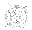
도 4는 본 발명에 유용한 배플의 일 실시예의 정면도.
도 5는 본 발명에 유용한 배플의 다른 실시예의 측단면도.1 is a cross-sectional view of one embodiment of a burner incorporating the present invention.
2 is a perspective view from the outside of the embodiment shown in FIG. 1;
3 is a side cross-sectional view of one embodiment of a baffle useful in the present invention.
4 is a front view of one embodiment of a baffle useful in the present invention.
5 is a side cross-sectional view of another embodiment of a baffle useful in the present invention.
본 발명은 매우 다양한 버너 구성에 적용가능하다. 이는, 연료와 산화제의 연소에 의해 형성되는 화염의 일 단부가 버너의 챔버 또는 인클로저(enclosure) 내부에 있어, 그 단부로부터 연장되는 화염의 일부분이 또한 버너의 챔버 또는 인클로저 내부에 있도록 하고, 화염의 나머지 부분이 버너의 개구 밖으로 연장되도록 하는 버너에 특히 유용하다.The present invention is applicable to a wide variety of burner configurations. This means that one end of the flame formed by the combustion of fuel and oxidant is inside the chamber or enclosure of the burner, so that a portion of the flame extending from that end is also inside the chamber or enclosure of the burner, It is particularly useful for burners in which the remainder extends out of the burner's opening.
도면들은 본 발명이 특히 유용한 버너의 몇몇 실시예를 예시한다.The figures illustrate some embodiments of burners in which the present invention is particularly useful.
하나의 그러한 버너의 단면도인 도 1을 먼저 참조한다. 버너(100)는 형상이 대체로 길이방향이며, 버너 내부에 챔버(1)를 함께 한정하는 측벽(9), 제1 단부(2), 및 제2 단부(3)를 포함한다. 단부(2, 3)들은 서로 길이방향으로 대향된다. 단부(2, 3)들 사이에서 길이방향 축에 수직으로 취해진 단면에서, 챔버(1)는 바람직한 원형 또는 직사각형일 수 있거나, 다른 형상의 것일 수 있다.Reference is first made to FIG. 1, which is a cross-sectional view of one such burner. The
제1 단부(2)는 개방되어, 챔버(1) 내에서 일 단부를 갖는 화염(22)이 화염 개구(4)를 통해 밖으로 버너(100) 외부의 공간으로 연장될 수 있다. 화염 개구(4)는 측벽(9)의 단부들에 의해 한정되는 전체 개구를 포함할 수 있다. 그러나, 본 발명은 제1 단부(2)가 단부 판(20)에 의해 부분적으로 폐쇄되어 화염 개구(4)의 면적이 측벽(9)의 단부들에 의해 한정되는 제1 단부(2)의 총 면적보다 작도록 된 실시예에서 특히 효과적이다. 제2 단부(3)는 폐쇄되고, 본 명세서에 기술된 바와 같이 제2 단부를 통과하는 하나 이상의 도관을 가질 수 있는데, 단, 제2 단부(3)와 임의의 그러한 도관 사이의 연결부는 연결부를 통과하는 가스에 대항하여 밀봉된다.The first end 2 is open such that a
도 2는 단부(2, 3)들 사이에서 연장되는 축에 수직인 단면이 원형인, 하나의 그러한 버너의 외형을 도시한다.2 shows the contour of one such burner, the cross section perpendicular to the axis extending between the
도 1을 다시 참조하면, 도관(10)은 버너(100) 외부로부터 챔버(1) 내로 통과하며, 도관(10)은 화염 개구(4)를 향해 개방된 도관 출구(12)에서 챔버(1) 내에서 종료되는데, 이는 도관 출구(12) 밖으로 통과하는 재료가 반드시 화염 개구(4)를 향해 이동하고 있음을 의미한다. 바람직하게는, 도관 출구(12)의 중심축은 화염 개구(4)를 통과한다. 도관(10)은 버너(100) 외부에 있는 도관 입구(11)를 포함한다. 도관 입구(11)는 챔버(1) 내에서 연소될 연료의 공급원에 연결될 수 있다. 적합한 연료는 임의의 가연성 기상 물질, 예를 들어 천연 가스, 메탄, 또는 다른 가연성 탄화수소 및 이들의 혼합물을 포함한다. 버너의 작동시, 도관 출구(12)로부터 나오는 연료가 화염(22) 중에서 연소되어, 화염(22)의 일 단부가 도관 출구(12)에 있도록 한다.Referring again to FIG. 1, the
통로(15)가 또한 제공된다. 이는 버너(100) 외부에 있는 통로 입구(16)로부터 챔버(1) 내부에 있는 통로 출구(17)로 연장된다. 통로 입구(16)는 도관(10)을 통해 공급되는 연료와 함께 챔버(1) 내에서 연소될 기상 산화제의 공급원에 연결될 수 있다. 적합한 기상 산화제는 공기, 산소-풍부 공기, 및 상업적 고순도 산소를 포함한다. 따라서, 기상 산화제의 산소 함량은 공기의 산소 함량(약 21 부피%) 내지 95 부피% 이상, 심지어 99 부피% 이상일 수 있다.A
본 발명의 버너는 또한 배플(5)을 포함한다. 도 1에서 볼 수 있는 바와 같이, 배플(5)은 제1 단부(2)를 향하는 제1 표면(42)을 포함하고, 배플(5)은 제2 단부(3)를 향하는 제2 표면(43)을 포함한다. 배플(5)은 배플(5) 둘레에서 완전히 연장되는 외측 에지(41)(도 3에 도시됨)를 포함한다. 외측 에지(41)는 챔버(1)의 내부 표면(13)에 인접하는데, 이는 외측 에지(41) 전부가 내부 표면(13)과 연속적으로 접촉하거나, 외측 에지(41) 전부 미만인 일부분이 내부 표면(13)과 접촉함을 의미한다. 외측 에지(41)가 내부 표면(13)과 접촉하지 않는 경우, 외측 에지(41)와 표면(13) 상의 최근접 지점 사이의 간극은 최대 1/4 인치(0.25 인치)이어야 한다. 배플(5)은 챔버(1)의 내부를 2개의 섹션, 즉 도관 출구(12)로부터 나오는 연료가 연소되는 연소 섹션(7) 및 후방 섹션(8)으로 분리한다. 따라서, 도관 출구(12) 및 통로 출구(17) 둘 모두는 챔버(1)의 연소 섹션(7) 내에 위치된다.The burner of the invention also includes a
도 1에서 볼 수 있는 바와 같이, 버너(100)는 도관(10)과 통로(15)가 버너(100)의 측벽(9)을 통과하는 위치들이 연소 섹션(7)에 있도록 구성될 수 있다. 그러나, 원한다면, 도관(11) 및/또는 (덜 바람직하게는) 통로(15)는 후방 섹션(8)을 통과하도록 위치될 수 있는데, 이 경우에 도관 또는 통로는 경우에 따라 그들의 각자의 출구들이 연소 섹션(7)에 있도록 배플(5)을 통과할 수 있다.As can be seen in FIG. 1, the
본 명세서에 기술된 바와 같은 배플(5)이 본 명세서에 기술된 바와 같은 버너의 구성 및 작동에 포함될 때, 버너의 작동은 배플이 없는 연소시에 관찰되는 것보다 훨씬 적은 소음 및 음향 공진을 수반한다는 것이 밝혀졌다. 제2 단부(3)의 내부 표면(6)으로부터 배플(5)의 제2 표면(43)까지의 거리가 5 내지 10 인치, 바람직하게는 약 6 인치이어야 하도록 배플(5)이 챔버(1) 내에 위치되어야 한다는 것이 밝혀졌다. 놀랍게도, 이러한 특징적인 거리가 버너의 다른 치수 및 버너의 작동 조건과 독립적이라는 것이 밝혀졌다.When the
배플은 도 3, 도 4 및 도 5를 참조하여 본 명세서에서 추가로 기술된다.Baffles are further described herein with reference to FIGS. 3, 4, and 5.
도 3은 전술된 바와 같은 제1 표면(42) 및 제2 표면(43)을 포함하는 바람직한 실시예의 배플(5)의 단면도를 도시한다. 배플(5)의 이러한 실시예에서, 2개의 구성요소, 즉 금속 판(44) 및 금속 필라멘트들의 층(46)이 있다.3 shows a cross-sectional view of the
금속 판(44)은 연소 섹션(7)에서 생성되는 연소 온도에서 그 형상을 유지하는 임의의 금속으로 제조된다. 적합한 금속의 예는 황동 및 강철을 포함한다. 금속 판(44)은 바람직하게는 두께가 1/8 인치 내지 1/2 인치이며, 여기서 두께는 금속 판(44)의 후방 표면(45)과 표면(42)사이의 거리로서 정의된다. 금속 판(44)은 배플(5)의 직경 폭 전체에 걸쳐, 즉 배플(5) 둘레 내내 에지(41)까지 내내 연장되어야 한다.The
도 3에서 그리고 도 4에서 볼 수 있는 바와 같이, 다수의 구멍(47)이 표면(42)으로부터 관통하여 표면(45)까지 금속 판(44)을 통과한다. 각각의 구멍은 바람직하게는 직경이 1/8 인치 내지 1/2 인치이다. 구멍들은 모두 동일한 직경일 수 있거나, 이들은 직경이 다를 수 있다. 표면(42) 내의 모든 구멍들의 개구들의 면적들의 합이 표면(42)의 총 표면적의 30% 내지 50%, 바람직하게는 약 40%이도록 충분한 구멍(47)들이 있어야 한다.As can be seen in FIG. 3 and in FIG. 4, a number of
배플(5)은 또한 금속 필라멘트들의 층(46)을 포함한다. 층(46)은 표면(45)과 접촉하여야 하지만, 물론 이러한 층(46)을 형성하는 재료의 전부가 표면(45)과 접촉할 필요는 없다. 48로서 나타낸 금속 필라멘트들은 각각 직경이 최대 0.005 인치이고, 재료의 일체 매트(mat)를 형성하기에 충분히 서로 랜덤으로 뒤얽힌다. 그러한 매트는, 매트의 단일의 일체 분량이 하나의 지점에서 파지되어 그 일체 분량이 그 하나의 지지점으로부터 매달리고 달리 지지되지 않도록 된 때, 그 일체 분량이 하나의 일체 분량으로서 유지되고 추가의 단편(piece)들로 파단되지 않는 경우에, 일체인 것으로 간주된다. 층(46)은 중실 블록이 아니라, 뒤얽힌 필라멘트들 사이에 공간들을 포함한다. 층의 (비압축) 밀도는 최대 0.5 온스/세제곱인치이어야 한다. 층(46)을 위한 재료의 적합한 예는 강철 울(steel wool) 또는 황동 울(brass wool)과 같은 "금속 울"로서 알려진 제품을 포함한다.The
배플(5) 내로 통합된 때의 층(46)은 챔버(1)의 단부(2, 3)들 사이에서 연장되는 축을 따라 1/4 인치(0.25 인치) 이상의 두께이어야 한다. 이러한 두께는 바람직하게는 최대 6 인치 두께이어야 한다. 후방 표면(43)과 내부 표면(6) 사이의 거리가 본 명세서에 기술된 바와 같이 유지된다면, 더 두꺼운 층이 허용가능하다. 감소된 음향 공진의 이득은, 층(46)의 두께의 각각의 추가 인치에 의해, 감소할 수 있다.The
도 5는 본 명세서에 기술된 바와 같은 금속 판(44) 및 층(46)을 포함하고 층(46)의 표면(43)과 접촉하는 제2 금속 판(49)을 또한 포함하는 배플(5)의 대안적인 실시예를 도시한다. 제2 금속 판(49)의 특성(제2 금속 판을 제조하는 재료, 두께, 폭, 구멍들의 존재, 구멍들의 면적들, 및 판(49)의 표면의 표면적에 대한 구멍들의 총 면적)은 금속 판(44)에 대해 본 명세서에 기술된 특성과 동일하다.5 includes a
버너의 작동시, 연료는 도관 출구(12)를 통해 챔버(1)의 연소 섹션(7) 내로 공급되고, 산화제는 통로 출구(17) 밖으로 챔버(1)의 연소 섹션(7) 내로 통과되고, 이들은 점화 및 연소된다. 연소는 기부가 출구(12)에 있는 화염을 형성한다. 화염은 화염 개구(4)를 통해 챔버(1) 밖으로 연장된다. 연료 및 산화제는 산화제 내의 산소가 연료를 완전히 연소시키는 데 필요한 산소의 양의 300 내지 20,000%를 구성하도록 상대 질량 유량으로 공급되어야 한다. 연소 전의 각각의 유동의 속도는 바람직하게는 5 내지 20 피트/초의 산소 유량 및 30 내지 50 피트/초의 연료 유량이다.In operation of the burner, fuel is supplied through the
Claims (16)
(A) 길이방향으로 대향된 제1 및 제2 단부들, 및 제1 단부를 통한 화염 개구를 갖는 챔버;
(B) 챔버의 내부 표면에 인접한 외측 에지(edge)를 갖는, 챔버 내의 배플(baffle) - 배플은 챔버의 제1 단부를 향해 대면하는 제1 표면을 갖고 챔버의 제2 단부를 향해 대면하는 제2 표면을 가지며, 배플은 제2 배플 표면이 챔버의 제2 단부의 내부 표면으로부터 5 내지 10 인치가 되도록 챔버 내에 위치됨 -;
(C) 챔버 외부의 도관 입구로부터 챔버 내로 연장되고, 제1 배플 표면과 화염 개구 사이에 있는 챔버의 섹션 내의 도관 출구에서 종료되는 도관 - 도관 출구는 화염 개구를 향해 개방됨 -;
(D) 챔버 외부의 통로 입구로부터 연장되고, 제1 배플 표면과 화염 개구 사이에 있는 챔버의 섹션 내의 통로 출구에서 종료되는 통로
를 포함하고,
배플은 (1) 화염 개구에 대면하는 제1 판 표면 및 챔버의 제2 단부에 대면하는 제2 판 표면을 갖는 금속 판, 및 (2) 제2 판 표면과 접촉하는 금속 필라멘트들의 층을 포함하며,
금속 판은 두께가 1/8 내지 1/2 인치이고, 직경이 1/8 내지 1/2 인치인 복수의 구멍들이 각각의 판 표면 내의 모든 구멍들의 개구들의 총 면적이 금속 판의 표면적의 30% 내지 50%가 되도록 충분한 개수의 구멍들로 제1 판 표면과 제2 판 표면 사이에서 금속 판을 통과하며,
금속 필라멘트들의 층은 0.25 인치 이상의 두께이고, 최대 0.5 온스/세제곱인치의 밀도를 나타내며, 최대 0.005 인치 두께의 필라멘트들로 구성되는, 버너.As a burner,
(A) a chamber having longitudinally opposed first and second ends and a flame opening through the first end;
(B) a baffle in the chamber having an outer edge adjacent to the interior surface of the chamber, the baffle having a first surface facing towards the first end of the chamber and facing towards the second end of the chamber; Having two surfaces, the baffle is positioned in the chamber such that the second baffle surface is 5 to 10 inches from the inner surface of the second end of the chamber;
(C) a conduit extending from the conduit inlet outside the chamber into the chamber and ending at the conduit outlet in the section of the chamber between the first baffle surface and the flame opening, wherein the conduit outlet opens toward the flame opening;
(D) A passage extending from the passage inlet outside the chamber and ending at the passage exit in the section of the chamber between the first baffle surface and the flame opening.
Including,
The baffle comprises (1) a metal plate having a first plate surface facing the flame opening and a second plate surface facing the second end of the chamber, and (2) a layer of metal filaments in contact with the second plate surface; ,
The metal plate has a thickness of 1/8 to 1/2 inch and a plurality of holes 1/8 to 1/2 inch in diameter have a total area of the openings of all the holes in each plate surface of 30% of the surface area of the metal plate. Passing through the metal plate between the first plate surface and the second plate surface with a sufficient number of holes to be from 50% to 50%,
The layer of metal filaments is at least 0.25 inches thick and exhibits a density of up to 0.5 oz / cubic inches and consists of filaments up to 0.005 inch thick.
Applications Claiming Priority (3)
| Application Number | Priority Date | Filing Date | Title |
|---|---|---|---|
| US201762529025P | 2017-07-06 | 2017-07-06 | |
| US62/529,025 | 2017-07-06 | ||
| PCT/US2018/039257 WO2019010025A1 (en) | 2017-07-06 | 2018-06-25 | Noise reduction in burners |
Publications (2)
| Publication Number | Publication Date |
|---|---|
| KR20200022005A true KR20200022005A (en) | 2020-03-02 |
| KR102254534B1 KR102254534B1 (en) | 2021-05-20 |
Family
ID=62948358
Family Applications (1)
| Application Number | Title | Priority Date | Filing Date |
|---|---|---|---|
| KR1020207002252A KR102254534B1 (en) | 2017-07-06 | 2018-06-25 | Reduce noise from burner |
Country Status (11)
| Country | Link |
|---|---|
| US (1) | US10520187B2 (en) |
| EP (1) | EP3649401B1 (en) |
| JP (1) | JP6931118B2 (en) |
| KR (1) | KR102254534B1 (en) |
| CN (1) | CN110998187B (en) |
| BR (1) | BR112020000231B1 (en) |
| CA (1) | CA3068959C (en) |
| CL (1) | CL2020000037A1 (en) |
| ES (1) | ES2875778T3 (en) |
| RU (1) | RU2728307C1 (en) |
| WO (1) | WO2019010025A1 (en) |
Families Citing this family (1)
| Publication number | Priority date | Publication date | Assignee | Title |
|---|---|---|---|---|
| US10920791B2 (en) * | 2018-10-03 | 2021-02-16 | Ford Global Technologies, Llc | Noise mitigating compressor |
Citations (3)
| Publication number | Priority date | Publication date | Assignee | Title |
|---|---|---|---|---|
| US3907489A (en) * | 1974-10-03 | 1975-09-23 | Selas Corp Of America | Noise suppressor for burner |
| CA2132997A1 (en) * | 1993-07-23 | 1995-12-08 | John V. Joyce | Gas-fired heaters with burners having a substantially sealed combustion chamber |
| US5791298A (en) * | 1995-11-07 | 1998-08-11 | Burner Systems International, Inc. | Water heater with low emission gas burner |
Family Cites Families (41)
| Publication number | Priority date | Publication date | Assignee | Title |
|---|---|---|---|---|
| US2805685A (en) | 1955-03-01 | 1957-09-10 | Hubert S Jopson | Restriction device |
| US3810732A (en) * | 1971-07-01 | 1974-05-14 | Siemens Ag | Method and apparatus for flameless combustion of gaseous or vaporous fuel-air mixtures |
| US3748085A (en) * | 1972-03-10 | 1973-07-24 | J Poepsel | Furnace silencers |
| US3819319A (en) | 1972-12-13 | 1974-06-25 | Hauck Mfg Co | Industrial pollution control systems and components thereof |
| US4375949A (en) * | 1978-10-03 | 1983-03-08 | Exxon Research And Engineering Co. | Method of at least partially burning a hydrocarbon and/or carbonaceous fuel |
| US4475621A (en) | 1982-09-10 | 1984-10-09 | Lennox Industries, Inc. | Sound reduction means for pulsating type furnace |
| WO1985005404A1 (en) | 1984-05-24 | 1985-12-05 | Bent Johansen | Sound absorption system, particularly for combustion engines |
| US4643667A (en) * | 1985-11-21 | 1987-02-17 | Institute Of Gas Technology | Non-catalytic porous-phase combustor |
| FR2628477B1 (en) * | 1988-03-11 | 1993-05-14 | Bertin & Cie | EJECTOR OR INJECTOR MUFFLER FOR THE EXPANSION OF A GASEOUS FLUID AND BLOWING DEVICE PROVIDED WITH AN ASSEMBLY OF SUCH A MUFFLER |
| DE3900723C1 (en) | 1989-01-12 | 1989-12-28 | Heidelberger Druckmaschinen Ag, 6900 Heidelberg, De | |
| US5236350A (en) | 1991-11-15 | 1993-08-17 | Maxon Corporation | Cyclonic combuster nozzle assembly |
| US5632236A (en) * | 1991-12-30 | 1997-05-27 | Bowin Technology Pty. Ltd. | Gas-fired heaters with burners which operate without secondary air and have a substantially sealed combustion chamber |
| GB2269892B (en) * | 1992-08-18 | 1995-09-06 | British Gas Plc | Fuel fired burners |
| US5575639A (en) * | 1994-03-31 | 1996-11-19 | Uniweld Products, Inc. | Combustion device orifice cleaner and method of cleaning |
| JPH0849808A (en) * | 1994-06-01 | 1996-02-20 | Matsushita Electric Ind Co Ltd | Combustion device |
| US5580238A (en) | 1995-12-18 | 1996-12-03 | Carrier Corporation | Baffle for NOx and noise reduction |
| US6106276A (en) | 1996-09-10 | 2000-08-22 | National Tank Company | Gas burner system providing reduced noise levels |
| US5879031A (en) | 1997-04-23 | 1999-03-09 | Carrier Corporation | Sound baffle installation and retention device |
| JPH11182817A (en) * | 1997-12-18 | 1999-07-06 | Nhk Spring Co Ltd | Surface combustion burner device |
| DE19851636A1 (en) | 1998-11-10 | 2000-05-11 | Asea Brown Boveri | Damping device for reducing vibration amplitude of acoustic waves for burner for internal combustion engine operation is preferably for driving gas turbo-group, with mixture area for air and fuel |
| US6161646A (en) * | 1999-08-17 | 2000-12-19 | Eaton Aeroquip Inc. | Turbo-generator exhaust noise silencer |
| US6343672B1 (en) * | 2000-03-23 | 2002-02-05 | Nova Gas Transmission Ltd. | Blowdown and venting jet noise suppressor |
| JP2002039514A (en) * | 2000-07-27 | 2002-02-06 | Tokyo Gas Co Ltd | Low-noise gas burner |
| US6530221B1 (en) | 2000-09-21 | 2003-03-11 | Siemens Westinghouse Power Corporation | Modular resonators for suppressing combustion instabilities in gas turbine power plants |
| DE10058688B4 (en) | 2000-11-25 | 2011-08-11 | Alstom Technology Ltd. | Damper arrangement for the reduction of combustion chamber pulsations |
| US7481650B2 (en) * | 2002-11-27 | 2009-01-27 | Midco International, Inc. | Direct gas-fired burner assembly with two-stage combustion |
| DE102004006647B4 (en) * | 2003-02-14 | 2015-02-26 | IfTA Ingenieurbüro für Thermoakustik GmbH | Method and device for discharging exhaust gas |
| US6923002B2 (en) | 2003-08-28 | 2005-08-02 | General Electric Company | Combustion liner cap assembly for combustion dynamics reduction |
| FR2884293B1 (en) | 2005-04-12 | 2007-05-18 | Sncf | ACOUSTICAL ATTENUATION DEVICE |
| CN200967298Y (en) * | 2006-06-21 | 2007-10-31 | 文黔军 | Metal mesh surface inner-tube combustion type combustor |
| CN200972118Y (en) * | 2006-11-17 | 2007-11-07 | 李建东 | Venturi oxygen-riched energy-saving burner |
| RU73054U1 (en) * | 2007-07-16 | 2008-05-10 | Открытое акционерное общество "Нижегородский машиностроительный завод" | GAS-BURNER |
| FR2938501B1 (en) * | 2008-11-14 | 2011-01-21 | Airbus France | METHOD FOR REDUCING THE NOISE GENERATED BY AN ORIFICE IN AN ENERGY GAS FLOW |
| GB0907578D0 (en) * | 2009-05-05 | 2009-06-10 | Rolls Royce Plc | A damping assembly |
| US8408004B2 (en) | 2009-06-16 | 2013-04-02 | General Electric Company | Resonator assembly for mitigating dynamics in gas turbines |
| US20110165527A1 (en) | 2010-01-06 | 2011-07-07 | General Electric Company | Method and Apparatus of Combustor Dynamics Mitigation |
| CN201688408U (en) * | 2010-04-09 | 2010-12-29 | 王战勇 | Negative-pressure low-noise burner |
| CN202361368U (en) * | 2011-06-21 | 2012-08-01 | 王玉秋 | Multi-fire-hole integrated type combustor |
| CN103471100B (en) * | 2013-09-13 | 2016-09-21 | 黄海卫 | The burner that the low firepower of noise is strong |
| CN204806390U (en) * | 2015-07-01 | 2015-11-25 | 慈溪正军厨具配件有限公司 | Silence kitchen range |
| CN206300218U (en) * | 2016-12-27 | 2017-07-04 | 重庆市开州区思源洗水有限公司 | A kind of silencing means of boiler combustion head |
-
2018
- 2018-06-22 US US16/015,348 patent/US10520187B2/en active Active
- 2018-06-25 CN CN201880051670.2A patent/CN110998187B/en active Active
- 2018-06-25 RU RU2020103238A patent/RU2728307C1/en active
- 2018-06-25 BR BR112020000231-3A patent/BR112020000231B1/en active IP Right Grant
- 2018-06-25 ES ES18742651T patent/ES2875778T3/en active Active
- 2018-06-25 CA CA3068959A patent/CA3068959C/en active Active
- 2018-06-25 WO PCT/US2018/039257 patent/WO2019010025A1/en unknown
- 2018-06-25 JP JP2020500186A patent/JP6931118B2/en active Active
- 2018-06-25 KR KR1020207002252A patent/KR102254534B1/en active IP Right Grant
- 2018-06-25 EP EP18742651.5A patent/EP3649401B1/en active Active
-
2020
- 2020-01-06 CL CL2020000037A patent/CL2020000037A1/en unknown
Patent Citations (3)
| Publication number | Priority date | Publication date | Assignee | Title |
|---|---|---|---|---|
| US3907489A (en) * | 1974-10-03 | 1975-09-23 | Selas Corp Of America | Noise suppressor for burner |
| CA2132997A1 (en) * | 1993-07-23 | 1995-12-08 | John V. Joyce | Gas-fired heaters with burners having a substantially sealed combustion chamber |
| US5791298A (en) * | 1995-11-07 | 1998-08-11 | Burner Systems International, Inc. | Water heater with low emission gas burner |
Also Published As
| Publication number | Publication date |
|---|---|
| BR112020000231B1 (en) | 2023-01-10 |
| CN110998187B (en) | 2021-09-03 |
| EP3649401A1 (en) | 2020-05-13 |
| CN110998187A (en) | 2020-04-10 |
| RU2728307C1 (en) | 2020-07-29 |
| WO2019010025A1 (en) | 2019-01-10 |
| EP3649401B1 (en) | 2021-04-07 |
| JP6931118B2 (en) | 2021-09-01 |
| CL2020000037A1 (en) | 2020-06-19 |
| US20190011125A1 (en) | 2019-01-10 |
| US10520187B2 (en) | 2019-12-31 |
| BR112020000231A2 (en) | 2020-07-07 |
| KR102254534B1 (en) | 2021-05-20 |
| CA3068959A1 (en) | 2019-01-10 |
| JP2020526729A (en) | 2020-08-31 |
| CA3068959C (en) | 2021-07-06 |
| ES2875778T3 (en) | 2021-11-11 |
Similar Documents
| Publication | Publication Date | Title |
|---|---|---|
| US4519770A (en) | Firetube boiler heater system | |
| JP4463427B2 (en) | Burner and method for operating a gas turbine | |
| KR102254534B1 (en) | Reduce noise from burner | |
| US20130255551A1 (en) | Biomass Combustion | |
| EP3336427A1 (en) | Gas burner | |
| US20050017203A1 (en) | Infrared emitter embodied as a planar emitter | |
| US20090311641A1 (en) | Gas flame stabilization method and apparatus | |
| ITMO970077A1 (en) | BURNER FOR GASEOUS FUELS | |
| CN107231800B (en) | Upwardly inclined burner in a glass furnace | |
| KR102233712B1 (en) | A multi-staged combined swirling combustion Device | |
| JP4720935B2 (en) | Burner equipment | |
| JP2014066414A (en) | Fire grade and incinerator using the same | |
| JP3754683B2 (en) | Vertical waste incinerator and method for controlling combustion of high calorific value waste in vertical waste incinerator | |
| RU2529436C1 (en) | Air heater with top heating | |
| US5588825A (en) | Lean premixed fuel burner | |
| JP2012517580A (en) | Seeding device | |
| JP5537299B2 (en) | Combustion chamber of waste treatment equipment | |
| WO2009151420A1 (en) | Gas flame stabilization method and apparatus | |
| KR101122156B1 (en) | Annealing furnace having surface burning burner for heating radiant tube | |
| RU2070687C1 (en) | Burner | |
| CN114576621A (en) | Combustion membrane for a burner | |
| US341883A (en) | Furnace | |
| SU1038719A2 (en) | Burner | |
| JP2004333099A (en) | Gas burner | |
| WO2014199015A1 (en) | Burner nozzle, burner and a surface treatment device |
Legal Events
| Date | Code | Title | Description |
|---|---|---|---|
| A201 | Request for examination | ||
| E701 | Decision to grant or registration of patent right | ||
| GRNT | Written decision to grant |