US5580238A - Baffle for NOx and noise reduction - Google Patents
Baffle for NOx and noise reduction Download PDFInfo
- Publication number
- US5580238A US5580238A US08/573,982 US57398295A US5580238A US 5580238 A US5580238 A US 5580238A US 57398295 A US57398295 A US 57398295A US 5580238 A US5580238 A US 5580238A
- Authority
- US
- United States
- Prior art keywords
- baffle
- heat exchanger
- burner
- perforations
- combustion apparatus
- Prior art date
- Legal status (The legal status is an assumption and is not a legal conclusion. Google has not performed a legal analysis and makes no representation as to the accuracy of the status listed.)
- Expired - Fee Related
Links
Images
Classifications
-
- F—MECHANICAL ENGINEERING; LIGHTING; HEATING; WEAPONS; BLASTING
- F23—COMBUSTION APPARATUS; COMBUSTION PROCESSES
- F23D—BURNERS
- F23D14/00—Burners for combustion of a gas, e.g. of a gas stored under pressure as a liquid
- F23D14/46—Details, e.g. noise reduction means
- F23D14/70—Baffles or like flow-disturbing devices
-
- F—MECHANICAL ENGINEERING; LIGHTING; HEATING; WEAPONS; BLASTING
- F23—COMBUSTION APPARATUS; COMBUSTION PROCESSES
- F23M—CASINGS, LININGS, WALLS OR DOORS SPECIALLY ADAPTED FOR COMBUSTION CHAMBERS, e.g. FIREBRIDGES; DEVICES FOR DEFLECTING AIR, FLAMES OR COMBUSTION PRODUCTS IN COMBUSTION CHAMBERS; SAFETY ARRANGEMENTS SPECIALLY ADAPTED FOR COMBUSTION APPARATUS; DETAILS OF COMBUSTION CHAMBERS, NOT OTHERWISE PROVIDED FOR
- F23M9/00—Baffles or deflectors for air or combustion products; Flame shields
- F23M9/06—Baffles or deflectors for air or combustion products; Flame shields in fire-boxes
-
- F—MECHANICAL ENGINEERING; LIGHTING; HEATING; WEAPONS; BLASTING
- F23—COMBUSTION APPARATUS; COMBUSTION PROCESSES
- F23C—METHODS OR APPARATUS FOR COMBUSTION USING FLUID FUEL OR SOLID FUEL SUSPENDED IN A CARRIER GAS OR AIR
- F23C2203/00—Flame cooling methods otherwise than by staging or recirculation
- F23C2203/20—Flame cooling methods otherwise than by staging or recirculation using heat absorbing device in flame
-
- F—MECHANICAL ENGINEERING; LIGHTING; HEATING; WEAPONS; BLASTING
- F23—COMBUSTION APPARATUS; COMBUSTION PROCESSES
- F23D—BURNERS
- F23D2210/00—Noise abatement
Definitions
- NO x may be produced in several ways, thermal NO x is associated with high temperatures, i.e. over 2800° F. The flame is zoned so that different parts of the flame are at different temperatures. NO x production can be reduced with the lowering of the peak flame temperature. The reduction in NO x can be achieved through turbulence of the gases being combusted and/or by heat transfer from the high temperature portion of the flame. Another problem associated with inshot burners employed in gas appliances such as furnaces is the production of excess noise during the operation of such gas burners.
- a ceramic fiber baffle is placed into a tubular heat exchanger in facing relationship with the burner such that the burner flame passes through the baffle which is of a spiral or involute shape.
- This configuration has the effect of making the flow path a spiral.
- the perforations in the spiral permit fluid communication between adjacent sections of the flow path separated by the perforate wall defining the spiral baffle.
- heat transfer to the tubular heat exchanger at the location of the baffle is increased which reduces flame temperature resulting in the reduction of the production of thermal NO x .
- the perforations in the spiral baffle cause flame turbulence which changes the harmonies in the tubular heat exchanger with a considerable reduction in noise.
- the perforations or holes are uniformly spaced apart and each has an area on the order of 0.08 to 0.11 square inches and together make up 55% to 75% of the surface area of the baffle.
- the spiral baffle extends from the heat exchanger in facing, spaced relation with the burner head.
- the baffle extends through the bell orifice or flame shaper so that all of the combustion air along with the flame is drawn through the baffle.
- the combustion air being drawn through the baffle cools the baffle thus cooling the burner flame.
- As the combustion air passes through the baffle it is heated and the heat from the combustion air is used downstream in the flame to help complete combustion.
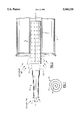
- FIG. 1 is a sectional view of a burner, baffle and heat exchanger
- FIG. 2 is an end view of the baffle.
- the numeral 10 generally designates the spiral, perforate baffle.
- Baffle 10 has an axis A, with a plurality of radially spaced turns defining a spiral channel or passage.
- Baffle 10 is preferably made of ceramic fiber, such as silicon carbide, but may be made of a high temperature alloy.
- Baffle 10 has a plurality of uniformly spaced perforations or holes 10-1 which are on the order of 0.08 to 0.11 square inches about 0.4 inches apart, on center, with a total porosity of 55% to 75% of the surface area of baffle 10.
- Baffle 10 has a nominal length of 6.0 inches and a nominal diameter of 2.125 inches.
- the turns of the spiral defining baffle 10 are nominally spaced 0.2 inches, 5 mm, apart.
- Baffle 10 is used in conjunction with an inshot burner 20 a heat exchanger 30 of existing design.
- the heat exchanger 10 is of tubular design.
- Baffle 10 is received in and supported by heat exchanger 10 such that one end extends from the heat exchanger on the order of 0.5 to 1.0 inches beyond bell orifice or flame shaper 32 and on the order of 2.0 inches from the burner head 20-1 of burner 20.
- gaseous fuel is supplied under pressure to port 21 of burner 20.
- the gas supplied to port 21 passes annular opening 22 aspirating atmospheric air which makes up the primary air and which is drawn into burner 20.
- the fuel/primary air mixture exits burner 20 in flame 50 which extends into baffle 10 and heat exchanger 30 which are positioned directly in the burner's flame 50.
- the secondary air performs two functions in that it cools baffle 10 as well as completing combustion of the fuel.
- the secondary air enters the baffle 10 axially with the primary air/fuel mixture, radially through the perforations 10-1 in the overhung portion of the baffle 10, and tangentially through the gap 12 between the outer end of the spiral and the adjacent turn in the overhung portion of baffle 10.
- the secondary air enters the baffle 10 due to aspiration.
- As the secondary air passes over the baffle 10 it cools the baffle 10.
- Baffle 10 also creates turbulence the burner flame pattern which changes tubular heat exchanger harmonic resonance and reduces burner noise. A major contributor to the turbulence is provided by the fluid communication between adjacent portions of the spiral flow path through baffle 10 due to perforations 10-1.
Landscapes
- Engineering & Computer Science (AREA)
- Chemical & Material Sciences (AREA)
- Combustion & Propulsion (AREA)
- Mechanical Engineering (AREA)
- General Engineering & Computer Science (AREA)
Abstract
A spiral, perforate ceramic baffle is placed into a heat exchanger in facing relationship with the burner and in an overhung relationship to the heat exchanger. A primary air/fuel mixture in the flame from the burner passes into the baffle drawing secondary air into the overhung portion of the baffle cooling the burner flame. Turbulence of the burner flame pattern in the baffle changes heat exchanger harmonic resonance and reduces burner noise.
Description
In the complete combustion of common gaseous fuels, the fuel combines with oxygen to produce carbon dioxide, water and heat. There can be intermediate reactions producing carbon monoxide and hydrogen. The heat, however, can also cause other chemical reactions such as causing atmospheric oxygen and nitrogen to combine to form oxides of nitrogen or NOx. While NOx may be produced in several ways, thermal NOx is associated with high temperatures, i.e. over 2800° F. The flame is zoned so that different parts of the flame are at different temperatures. NOx production can be reduced with the lowering of the peak flame temperature. The reduction in NOx can be achieved through turbulence of the gases being combusted and/or by heat transfer from the high temperature portion of the flame. Another problem associated with inshot burners employed in gas appliances such as furnaces is the production of excess noise during the operation of such gas burners.
A ceramic fiber baffle is placed into a tubular heat exchanger in facing relationship with the burner such that the burner flame passes through the baffle which is of a spiral or involute shape. This configuration has the effect of making the flow path a spiral. The perforations in the spiral permit fluid communication between adjacent sections of the flow path separated by the perforate wall defining the spiral baffle. As the flame passes through the baffle, heat transfer to the tubular heat exchanger at the location of the baffle is increased which reduces flame temperature resulting in the reduction of the production of thermal NOx. Additionally, the perforations in the spiral baffle cause flame turbulence which changes the harmonies in the tubular heat exchanger with a considerable reduction in noise. Preferably, the perforations or holes are uniformly spaced apart and each has an area on the order of 0.08 to 0.11 square inches and together make up 55% to 75% of the surface area of the baffle.
It is an object of this invention to provide a low flame profile and relatively low flame temperatures in existing inshot burners.
It is another object of this invention to provide an inshot gas burner assembly which operates with reduced noise and resonance.
It is a further object of this invention to reduce the production of thermal NOx. These objects, and others as will become apparent hereinafter, are accomplished by the present invention.
Basically, the spiral baffle extends from the heat exchanger in facing, spaced relation with the burner head. The baffle extends through the bell orifice or flame shaper so that all of the combustion air along with the flame is drawn through the baffle. The combustion air being drawn through the baffle cools the baffle thus cooling the burner flame. As the combustion air passes through the baffle it is heated and the heat from the combustion air is used downstream in the flame to help complete combustion.
For a fuller understanding of the present invention, reference should now be made to the following detailed description thereof taken in conjunction with the accompanying drawings wherein:
FIG. 1 is a sectional view of a burner, baffle and heat exchanger; and
FIG. 2 is an end view of the baffle.
In the Figures, the numeral 10 generally designates the spiral, perforate baffle. Baffle 10 has an axis A, with a plurality of radially spaced turns defining a spiral channel or passage. Baffle 10 is preferably made of ceramic fiber, such as silicon carbide, but may be made of a high temperature alloy. Baffle 10 has a plurality of uniformly spaced perforations or holes 10-1 which are on the order of 0.08 to 0.11 square inches about 0.4 inches apart, on center, with a total porosity of 55% to 75% of the surface area of baffle 10. Baffle 10 has a nominal length of 6.0 inches and a nominal diameter of 2.125 inches. The turns of the spiral defining baffle 10 are nominally spaced 0.2 inches, 5 mm, apart.
Baffle 10 is used in conjunction with an inshot burner 20 a heat exchanger 30 of existing design. For example, the heat exchanger 10 is of tubular design. Baffle 10 is received in and supported by heat exchanger 10 such that one end extends from the heat exchanger on the order of 0.5 to 1.0 inches beyond bell orifice or flame shaper 32 and on the order of 2.0 inches from the burner head 20-1 of burner 20.
In operation, gaseous fuel is supplied under pressure to port 21 of burner 20. The gas supplied to port 21 passes annular opening 22 aspirating atmospheric air which makes up the primary air and which is drawn into burner 20. The fuel/primary air mixture exits burner 20 in flame 50 which extends into baffle 10 and heat exchanger 30 which are positioned directly in the burner's flame 50. As the flame 50 made up of the primary air/fuel mix flows axially into the spiral defined by baffle 10, secondary air is being drawn in. The secondary air performs two functions in that it cools baffle 10 as well as completing combustion of the fuel. The secondary air enters the baffle 10 axially with the primary air/fuel mixture, radially through the perforations 10-1 in the overhung portion of the baffle 10, and tangentially through the gap 12 between the outer end of the spiral and the adjacent turn in the overhung portion of baffle 10. The secondary air enters the baffle 10 due to aspiration. As the secondary air passes over the baffle 10 it cools the baffle 10. After the secondary air passes through the baffle 10 it retains enough heat from heat transfer from the baffle 10 to the secondary air to keep the flame temperature high enough to complete the combustion during the later stages. Baffle 10 also creates turbulence the burner flame pattern which changes tubular heat exchanger harmonic resonance and reduces burner noise. A major contributor to the turbulence is provided by the fluid communication between adjacent portions of the spiral flow path through baffle 10 due to perforations 10-1.
Although a preferred embodiment of the present invention has been described and illustrated, other changes will occur to those skilled in the art. It is therefore intended that the scope of the present invention is to be limited only by the scope of the appended claims.
Claims (16)
1. A baffle for reducing NOx and changing heat exchanger harmonic resonance comprising:
a heat resistant member formed as a spiral relative to an axis with a plurality of radially spaced turns;
said member having a plurality of perforations therein providing fluid communication between regions separated by said spaced turns;
whereby when said baffle is placed in a heat exchanger opposite a burner, flow made up of a flame containing a mixture of fuel and primary air flows axially into said baffle from the burner drawing secondary air into said baffle which cools said baffle and creates turbulence thereby reducing NOx production and changing heat exchanger harmonic resonance.
2. The baffle of claim 1 wherein secondary air enters said baffle axially, radially and tangentially.
3. The baffle of claim 1 wherein when said baffle is placed in an overhung relationship to the heat exchanger secondary air enters said baffle axially, radially and tangentially in the overhung portion.
4. The baffle of claim 1 wherein said perforations make up 55% to 75% of said baffle.
5. The baffle of claim 4 wherein said perforations are each on the order of 0.08 to 0.11 square inches.
6. The baffle of claim 1 wherein said perforations are each on the order of 0.08 to 0.11 square inches.
7. The baffle of claim 1 wherein said member is made of ceramic fiber.
8. The baffle of claim 1 wherein said member is made of high temperature alloy.
9. In a combustion apparatus having an inshot burner with a heat exchanger in facing relationship with said burner the improvement comprising:
a heat resistant member formed as a spiral relative to an axis with a plurality of radially spaced turns;
said member having a plurality of perforations therein providing fluid communication between regions separated by said spaced turns;
whereby flow made up of a flame containing a mixture of fuel and primary air flows axially into said baffle from said burner drawing secondary air into said baffle which cools said baffle and creates turbulence thereby reducing NOx production and changing heat exchanger harmonic.
10. The combustion apparatus of claim 9 wherein secondary air enters said baffle axially, radially and tangentially.
11. The combustion apparatus of claim 9 wherein when said baffle is placed in an overhung relationship to the heat exchanger secondary air enters said baffle axially, radially and tangentially in the overhung portion.
12. The combustion apparatus of claim 9 wherein said perforations make up 55% to 75% of said baffle.
13. The combustion apparatus of claim 12 wherein said perforations are each on the order of 0.08 to 0.11 square inches.
14. The combustion apparatus of claim 9 wherein said perforations are each on the order of 0.08 to 0.11 square inches.
15. The combustion apparatus of claim 9 wherein said member is made of ceramic fiber.
16. In the combustion apparatus of claim 9 wherein said member is made of high temperature alloy.
Priority Applications (2)
| Application Number | Priority Date | Filing Date | Title |
|---|---|---|---|
| US08/573,982 US5580238A (en) | 1995-12-18 | 1995-12-18 | Baffle for NOx and noise reduction |
| EP96630072A EP0780637A3 (en) | 1995-12-18 | 1996-11-29 | Baffle for Nox and noise reduction |
Applications Claiming Priority (1)
| Application Number | Priority Date | Filing Date | Title |
|---|---|---|---|
| US08/573,982 US5580238A (en) | 1995-12-18 | 1995-12-18 | Baffle for NOx and noise reduction |
Publications (1)
| Publication Number | Publication Date |
|---|---|
| US5580238A true US5580238A (en) | 1996-12-03 |
Family
ID=24294196
Family Applications (1)
| Application Number | Title | Priority Date | Filing Date |
|---|---|---|---|
| US08/573,982 Expired - Fee Related US5580238A (en) | 1995-12-18 | 1995-12-18 | Baffle for NOx and noise reduction |
Country Status (2)
| Country | Link |
|---|---|
| US (1) | US5580238A (en) |
| EP (1) | EP0780637A3 (en) |
Cited By (12)
| Publication number | Priority date | Publication date | Assignee | Title |
|---|---|---|---|---|
| EP0813028A2 (en) * | 1996-06-10 | 1997-12-17 | Carrier Corporation | Burner emission device |
| US6106276A (en) * | 1996-09-10 | 2000-08-22 | National Tank Company | Gas burner system providing reduced noise levels |
| US6138662A (en) * | 1994-09-30 | 2000-10-31 | Philomena Joan Jones | Heaters |
| US6485294B2 (en) * | 2000-12-20 | 2002-11-26 | Lennox Manufacturing Inc. | NOx reduction device |
| US20030098198A1 (en) * | 2001-09-05 | 2003-05-29 | Webasto Thermosysteme International Gmbh | Auxiliary heater arrangement with a muffler |
| US20090098496A1 (en) * | 2007-10-16 | 2009-04-16 | Lennox Manufacturing Inc. | Heat exchanger with nox-reducing triangle |
| US20130164697A1 (en) * | 2011-12-27 | 2013-06-27 | Rinnai Corporation | Combustion Apparatus |
| US20150159868A1 (en) * | 2013-12-10 | 2015-06-11 | Carrier Corporation | Igniter and flame sensor assembly with opening |
| US20150192292A1 (en) * | 2012-07-03 | 2015-07-09 | Ulrich Dreizler | Surface combustion burner |
| US20180271326A1 (en) * | 2017-03-24 | 2018-09-27 | Alto-Shaam, Inc. | Gas Heat Exchanger with Baffle for Deep Fat Fryer |
| US10520187B2 (en) | 2017-07-06 | 2019-12-31 | Praxair Technology, Inc. | Burner with baffle |
| US10982848B2 (en) | 2018-05-21 | 2021-04-20 | Carrier Corporation | Baffle design for furnace burner box |
Citations (7)
| Publication number | Priority date | Publication date | Assignee | Title |
|---|---|---|---|---|
| US2059523A (en) * | 1936-11-03 | Heating apparatus | ||
| US2396868A (en) * | 1941-09-08 | 1946-03-19 | Mccollum Thelma | Liquid fuel combustion apparatus |
| US3732059A (en) * | 1971-05-28 | 1973-05-08 | Zink Co John | Burner for gaseous fuels in reduced oxygen and/or significant velocity atmosphere |
| US4619604A (en) * | 1983-06-30 | 1986-10-28 | Carrier Corporation | Flame radiator structure |
| US4869230A (en) * | 1986-06-04 | 1989-09-26 | Ambi-Rad Limited | Space heating appliance |
| US5049066A (en) * | 1989-10-25 | 1991-09-17 | Tokyo Gas Company Limited | Burner for reducing NOx emissions |
| US5240411A (en) * | 1992-02-10 | 1993-08-31 | Mor-Flo Industries, Inc. | Atmospheric gas burner assembly |
Family Cites Families (2)
| Publication number | Priority date | Publication date | Assignee | Title |
|---|---|---|---|---|
| US2204036A (en) * | 1938-07-16 | 1940-06-11 | Filippo Abramo Di | Baffle for furnaces |
| CH416015A (en) * | 1962-02-26 | 1966-06-30 | Ygnis Ag | Boiler with liquid-flushed cavities through which smoke gas flows |
-
1995
- 1995-12-18 US US08/573,982 patent/US5580238A/en not_active Expired - Fee Related
-
1996
- 1996-11-29 EP EP96630072A patent/EP0780637A3/en not_active Ceased
Patent Citations (7)
| Publication number | Priority date | Publication date | Assignee | Title |
|---|---|---|---|---|
| US2059523A (en) * | 1936-11-03 | Heating apparatus | ||
| US2396868A (en) * | 1941-09-08 | 1946-03-19 | Mccollum Thelma | Liquid fuel combustion apparatus |
| US3732059A (en) * | 1971-05-28 | 1973-05-08 | Zink Co John | Burner for gaseous fuels in reduced oxygen and/or significant velocity atmosphere |
| US4619604A (en) * | 1983-06-30 | 1986-10-28 | Carrier Corporation | Flame radiator structure |
| US4869230A (en) * | 1986-06-04 | 1989-09-26 | Ambi-Rad Limited | Space heating appliance |
| US5049066A (en) * | 1989-10-25 | 1991-09-17 | Tokyo Gas Company Limited | Burner for reducing NOx emissions |
| US5240411A (en) * | 1992-02-10 | 1993-08-31 | Mor-Flo Industries, Inc. | Atmospheric gas burner assembly |
Cited By (19)
| Publication number | Priority date | Publication date | Assignee | Title |
|---|---|---|---|---|
| US6138662A (en) * | 1994-09-30 | 2000-10-31 | Philomena Joan Jones | Heaters |
| EP0813028A2 (en) * | 1996-06-10 | 1997-12-17 | Carrier Corporation | Burner emission device |
| EP0813028A3 (en) * | 1996-06-10 | 1998-11-18 | Carrier Corporation | Burner emission device |
| US5961320A (en) * | 1996-06-10 | 1999-10-05 | Carrier Corporation | Burner emission device |
| US6106276A (en) * | 1996-09-10 | 2000-08-22 | National Tank Company | Gas burner system providing reduced noise levels |
| US6485294B2 (en) * | 2000-12-20 | 2002-11-26 | Lennox Manufacturing Inc. | NOx reduction device |
| US20030098198A1 (en) * | 2001-09-05 | 2003-05-29 | Webasto Thermosysteme International Gmbh | Auxiliary heater arrangement with a muffler |
| US7011179B2 (en) * | 2001-09-05 | 2006-03-14 | Webasto Thermosysteme Internatonal Gmbh | Auxiliary heater arrangement with a muffler |
| US20090098496A1 (en) * | 2007-10-16 | 2009-04-16 | Lennox Manufacturing Inc. | Heat exchanger with nox-reducing triangle |
| US20130164697A1 (en) * | 2011-12-27 | 2013-06-27 | Rinnai Corporation | Combustion Apparatus |
| US9127839B2 (en) * | 2011-12-27 | 2015-09-08 | Rinnai Corporation | Combustion apparatus |
| US20150192292A1 (en) * | 2012-07-03 | 2015-07-09 | Ulrich Dreizler | Surface combustion burner |
| US10605451B2 (en) * | 2012-07-03 | 2020-03-31 | Ulrich Dreizler | Surface combustion burner |
| US20150159868A1 (en) * | 2013-12-10 | 2015-06-11 | Carrier Corporation | Igniter and flame sensor assembly with opening |
| US9915425B2 (en) * | 2013-12-10 | 2018-03-13 | Carrier Corporation | Igniter and flame sensor assembly with opening |
| US20180271326A1 (en) * | 2017-03-24 | 2018-09-27 | Alto-Shaam, Inc. | Gas Heat Exchanger with Baffle for Deep Fat Fryer |
| US10888197B2 (en) * | 2017-03-24 | 2021-01-12 | Alto-Shaam, Inc. | Gas heat exchanger with baffle for deep fat fryer |
| US10520187B2 (en) | 2017-07-06 | 2019-12-31 | Praxair Technology, Inc. | Burner with baffle |
| US10982848B2 (en) | 2018-05-21 | 2021-04-20 | Carrier Corporation | Baffle design for furnace burner box |
Also Published As
| Publication number | Publication date |
|---|---|
| EP0780637A3 (en) | 1998-05-13 |
| EP0780637A2 (en) | 1997-06-25 |
Similar Documents
| Publication | Publication Date | Title |
|---|---|---|
| US5624252A (en) | Low no burner | |
| US4239481A (en) | Double orifice vortex burner for low or high Wobbe fuels | |
| US5580238A (en) | Baffle for NOx and noise reduction | |
| US5195884A (en) | Low NOx formation burner apparatus and methods | |
| US7112060B2 (en) | Burner for treating waste gas | |
| JP2588355B2 (en) | Oxy-fuel combustion equipment | |
| US6638057B2 (en) | Partial oxidation of hydrogen sulphide | |
| US6036481A (en) | Burner with flame retainer insert | |
| US4304549A (en) | Recuperator burner for industrial furnaces | |
| US6485294B2 (en) | NOx reduction device | |
| US5746194A (en) | Catalytic insert for NOx reduction | |
| US5596979A (en) | Sound inhibitor baffles | |
| CA1103574A (en) | Burner for very low pressure gases | |
| EP0461729B1 (en) | Premix gas burner having a high turn down ratio | |
| US5597301A (en) | Burner emission device | |
| US5961320A (en) | Burner emission device | |
| Charles Sr et al. | Baffle for NO x and noise reduction | |
| EP0486285A2 (en) | Burners | |
| WO1998040670A1 (en) | AN IMPROVED COMBUSTOR FOR LOW CO, LOW NOx FORMATION | |
| JPS5883112A (en) | Burner | |
| SU985572A1 (en) | Burner | |
| SU1288447A1 (en) | Injection burner and method of its operation | |
| JP2000283422A (en) | Burner device | |
| JPH03158610A (en) | Burner | |
| JPH1137425A (en) | Burner |
Legal Events
| Date | Code | Title | Description |
|---|---|---|---|
| AS | Assignment |
Owner name: CARRIER CORPORATION, CONNECTICUT Free format text: ASSIGNMENT OF ASSIGNORS INTEREST;ASSIGNORS:CHARLES, JOHN G., SR.;DADDIS, EUGENE D., JR.;REEL/FRAME:007985/0619;SIGNING DATES FROM 19951213 TO 19951214 |
|
| REMI | Maintenance fee reminder mailed | ||
| LAPS | Lapse for failure to pay maintenance fees | ||
| FP | Expired due to failure to pay maintenance fee |
Effective date: 20001203 |
|
| STCH | Information on status: patent discontinuation |
Free format text: PATENT EXPIRED DUE TO NONPAYMENT OF MAINTENANCE FEES UNDER 37 CFR 1.362 |